FOUNDATIONS - Arch Exam Academy Systems...Foundations Copyright © G G Schierle, 2006 Press Esc to...
32
Foundations Copyright © G G Schierle, 2006 Press Esc to end, ↓ for next, ↑ for previous slide 1 FOUNDATIONS
Transcript of FOUNDATIONS - Arch Exam Academy Systems...Foundations Copyright © G G Schierle, 2006 Press Esc to...
Foundations Copyright © G G Schierle, 2006 Press Esc to end, ↓ for next, ↑ for previous slide 1
FOUNDATIONS

Foundations Copyright © G G Schierle, 2006 Press Esc to end, ↓ for next, ↑ for previous slide 2
Liquefaction reduced the soil strength under these apartment buildings in Niigata (Japan) 1964.
Liquefied soil exerts higher pressure on retaining walls, displace them and cause settlement of retained soil.
LiquefactionLiquefaction reduces soil strength and stiffnessby earthquakes shaking. Liquefaction causedgreat damage in past earthquakes.
Liquefaction occurs in sandy soil saturated withwater. Earthquakes increase the water pressureto make the soil liquid.

Foundations Copyright © G G Schierle, 2006 Press Esc to end, ↓ for next, ↑ for previous slide 3
LandslideLandslides are movements of surfacematerial down a slope. Landslides may be caused by earthquakes.
During a Northridge Earthquake aftershocklandslide dust blows eerily out of the SantaSusana Mountains into the Simi Valley

Foundations Copyright © G G Schierle, 2006 Press Esc to end, ↓ for next, ↑ for previous slide 4
To avoidexpensiveearthquakesettlementrepair …...
Sustainable hill site design

Foundations Copyright © G G Schierle, 2006 Press Esc to end, ↓ for next, ↑ for previous slide 5
Buildings adapted to site to avoid differential grading settlement
to reduces gradingand retaining wallsand avoid expensivesettlement repairs ☺
.……… adapt buildings to site – instead of adapting site to buildings

Foundations Copyright © G G Schierle, 2006 Press Esc to end, ↓ for next, ↑ for previous slide 6
Soil Capacity Soil type Soil capacity (approximate)Soft clay 2 ksf 100 kPaStiff clay 4 ksf 200 kPaSand, compacted 6 ksf 300 kPaGravel 15 ksf 700 kPaSedimentary rock 50 ksf 2400 kPaHard rock (granite) 200 ksf 9600 kPa

Foundations Copyright © G G Schierle, 2006 Press Esc to end, ↓ for next, ↑ for previous slide 7
1 Shallow footing (in areas of no frost)2 Frost-free footing (depth per map below)A Slab on grade, 4” with welded wire mesh (8” edge resists shear)B Gravel bed and waterproof membraneC Base plate, pressure treated, min 6” above gradeD Plywood sheathingE Anchor bolts at max. 4’ o. c. F Footing rebarsG CMU stem wall with dowel bars & waterproof membraneH Stem wall keyI Perforated drain pipe at base of footingJ Gravel bed
Footing depthsWood framing example
Fros
t pen
etra
tion
map
Foundations Copyright © G G Schierle, 2006 Press Esc to end, ↓ for next, ↑ for previous slide 8
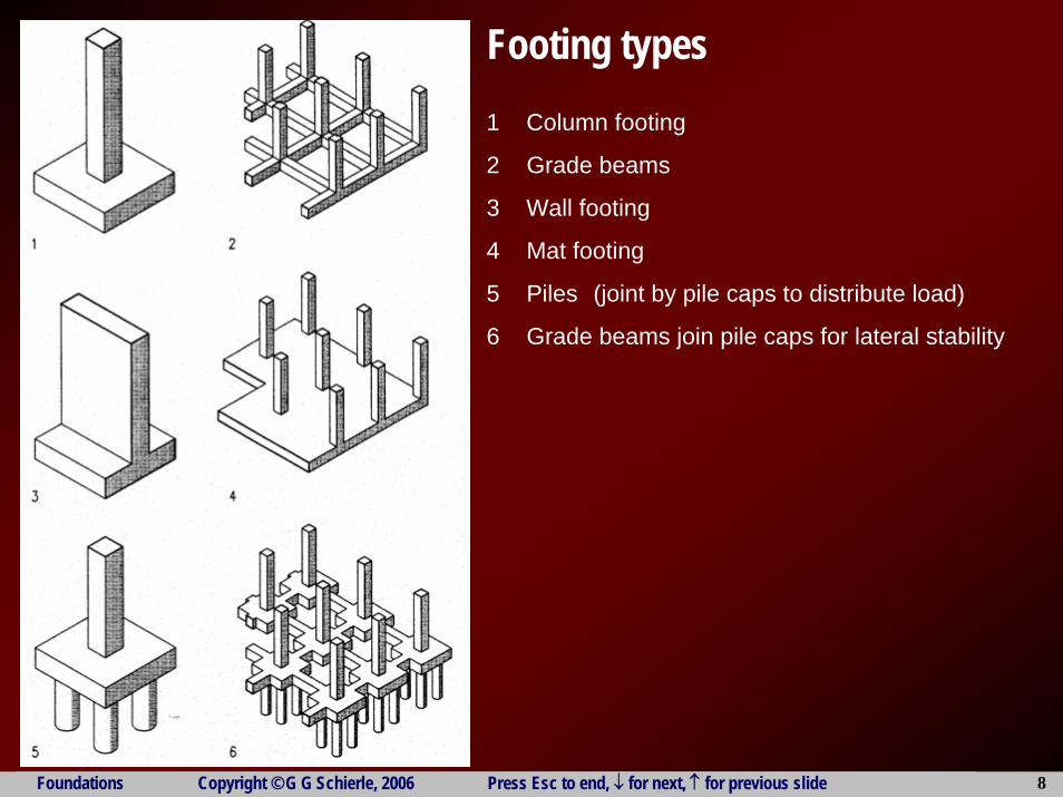
Footing types1 Column footing
2 Grade beams
3 Wall footing
4 Mat footing
5 Piles (joint by pile caps to distribute load)
6 Grade beams join pile caps for lateral stability

Foundations Copyright © G G Schierle, 2006 Press Esc to end, ↓ for next, ↑ for previous slide 9
Footing type use
Foundations Copyright © G G Schierle, 2006 Press Esc to end, ↓ for next, ↑ for previous slide 10
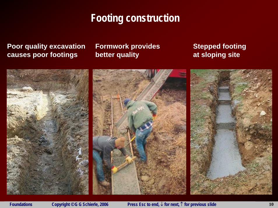
Poor quality excavationcauses poor footings
Stepped footingat sloping site
Formwork providesbetter quality
Footing construction
Foundations Copyright © G G Schierle, 2006 Press Esc to end, ↓ for next, ↑ for previous slide 11
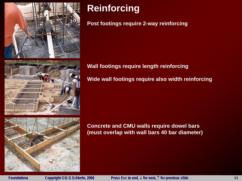
ReinforcingPost footings require 2-way reinforcing
Wall footings require length reinforcing
Wide wall footings require also width reinforcing
Concrete and CMU walls require dowel bars(must overlap with wall bars 40 bar diameter)

Foundations Copyright © G G Schierle, 2006 Press Esc to end, ↓ for next, ↑ for previous slide 12
Hold-down & post baseTo resist overturning, wood shear wallsrequire hold-downs at both sides
Hold-down ties wall to footing
Twin hold-downs tietop wall to wall below
Post base ties post to footing
Foundations Copyright © G G Schierle, 2006 Press Esc to end, ↓ for next, ↑ for previous slide 13
Wall
footi
ngW
ith st
em w
allan
d cra
wl sp
ace
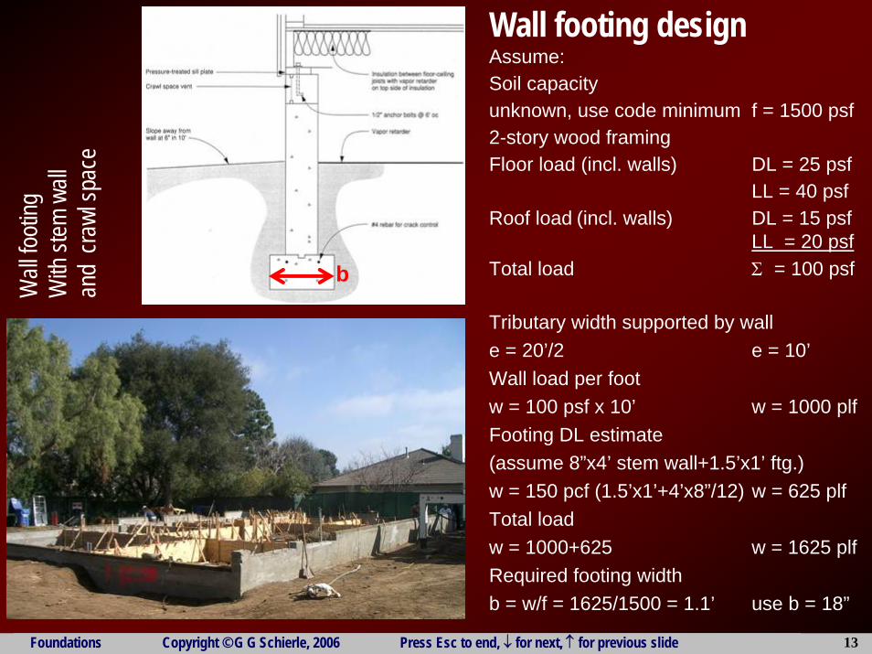
Wall footing designAssume: Soil capacity unknown, use code minimum f = 1500 psf2-story wood framingFloor load (incl. walls) DL = 25 psf
LL = 40 psfRoof load (incl. walls) DL = 15 psf
LL = 20 psfTotal load Σ = 100 psf
Tributary width supported by walle = 20’/2 e = 10’Wall load per footw = 100 psf x 10’ w = 1000 plfFooting DL estimate(assume 8”x4’ stem wall+1.5’x1’ ftg.)w = 150 pcf (1.5’x1’+4’x8”/12) w = 625 plfTotal loadw = 1000+625 w = 1625 plfRequired footing widthb = w/f = 1625/1500 = 1.1’ use b = 18”
b

Foundations Copyright © G G Schierle, 2006 Press Esc to end, ↓ for next, ↑ for previous slide 14
Base
men
t wall
Conc
rete
or C
MU (c
ost le
ss)
Note:
if gr
eat fr
ost d
epth
is re
quire
d, ba
seme
nts ar
e cos
t-effe
ctive

Foundations Copyright © G G Schierle, 2006 Press Esc to end, ↓ for next, ↑ for previous slide 15
Concrete wall footing designAssume: Soil capacity Soft clay f = 2000 psf2-story concreteFloor load (incl. walls) DL = 170 psf
LL = 50 psfRoof load (incl. walls) DL = 120 psf
LL = 20 psfTotal load Σ = 360 psf
Tributary width supported by walle = 20’/2 e = 10’Wall load per footw = 360 psf x 10’ w = 3,600 plfFooting DL estimate(12” basement wall, 9’ high)w = 150 pcf (3’x1.5’+1’x9’) w = 2,025 plfTotal loadw = 3,600+2,025 w = 5,625 plfRequired footing widthb = w/f = 5,625/2000 = 2.8’ use b = 3’

Foundations Copyright © G G Schierle, 2006 Press Esc to end, ↓ for next, ↑ for previous slide 16
Post footing DesignAssume:2-story buildingSoil capacity (stiff clay) f = 4 ksfLoads: 150 psf DL + 50 psf LL Σ = 200 psfTributary area A = 30’x30’ A = 900 ft2Post load P = 2x200x900/1000 P = 360 kFooting DL (estimate 10x10’x18”)P = 10’x10’x1.5’x150 pcf/1000 P = 23 kRequired Footing areaAf = P/f =(360+23)/4 ksf Af = 96 ft2Footing sizeb = Af
1/2 = 961/2 = 9.8’ use 10’x10’x18”

Foundations Copyright © G G Schierle, 2006 Press Esc to end, ↓ for next, ↑ for previous slide 17
Post template with anchor bolts, furnished by steel fabricator, installed in concrete footing
Post with base plate, replacing template, attached to anchor bolts
Twin nuts to align postprior to grouting
Grouting
Steel column base

Foundations Copyright © G G Schierle, 2006 Press Esc to end, ↓ for next, ↑ for previous slide 18
Steel erection

Foundations Copyright © G G Schierle, 2006 Press Esc to end, ↓ for next, ↑ for previous slide 19
Construction steps:
1 Excavate

Foundations Copyright © G G Schierle, 2006 Press Esc to end, ↓ for next, ↑ for previous slide 20
Construction steps:
2 Place reinforcingDowel bars must overlap post/wall bars minimum 40 bar diameters

Foundations Copyright © G G Schierle, 2006 Press Esc to end, ↓ for next, ↑ for previous slide 21
Construction steps:
3 Place concrete
Foundations Copyright © G G Schierle, 2006 Press Esc to end, ↓ for next, ↑ for previous slide 22
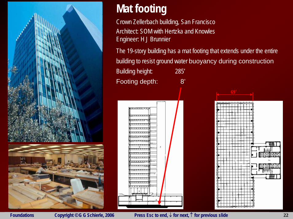
Mat footingCrown Zellerbach building, San FranciscoArchitect: SOM with Hertzka and KnowlesEngineer: H J Brunnier
The 19-story building has a mat footing that extends under the entirebuilding to resist ground water buoyancy during constructionBuilding height: 285’Footing depth: 8’
69’

Foundations Copyright © G G Schierle, 2006 Press Esc to end, ↓ for next, ↑ for previous slide 23
Pile and caissonPiles and caissons/piers are used in poor soil to increase bearing capacity
Piles are driven into soil Caissons/piers are cast into shafts that areexcavated or drilled
1 Steel H-pile2 Timber pile3 Concrete piles4 Piles
Left: end-bearing pileRight: friction pile
5 Caissons/piersLeft: Caisson with bell to increase bearingRight: straight caisson
6 Pile caps
Foundations Copyright © G G Schierle, 2006 Press Esc to end, ↓ for next, ↑ for previous slide 24
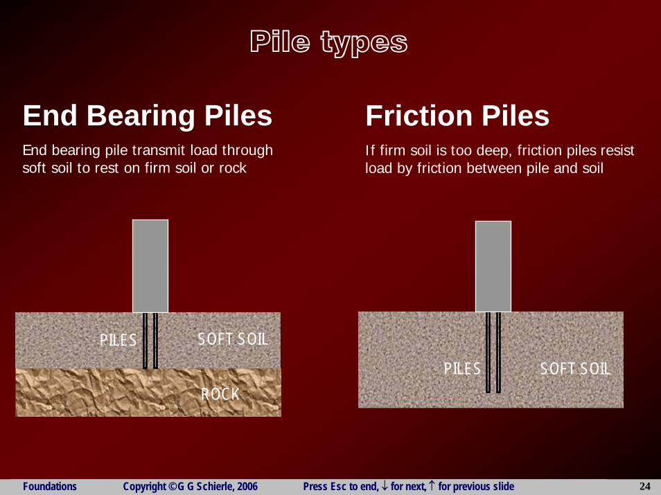
ROCK
SOFT SOILPILES
End Bearing PilesEnd bearing pile transmit load through soft soil to rest on firm soil or rock
Friction PilesIf firm soil is too deep, friction piles resist load by friction between pile and soil
SOFT SOILPILES
Pile types

Foundations Copyright © G G Schierle, 2006 Press Esc to end, ↓ for next, ↑ for previous slide 25
Pile drivingCason/pier drilling

Foundations Copyright © G G Schierle, 2006 Press Esc to end, ↓ for next, ↑ for previous slide 26
Retaining walls1-3 Mass retaining walls4 Concrete / CMU wall
at property line with adjacent land lower5 Concrete / CMU wall6 Concrete / CMU wall
at property line with adjacent land higher7 Concrete / CMU wall with shear key8 Concrete / CMU wall with shear key9 Concrete / CMU wall with shear keyNote: shear key adds lateral resistance
Floor bracing
Temporary bracing
Foundations Copyright © G G Schierle, 2006 Press Esc to end, ↓ for next, ↑ for previous slide 27
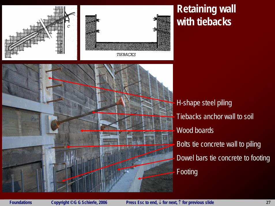
H-shape steel piling
Tiebacks anchor wall to soil
Wood boards
Bolts tie concrete wall to piling
Dowel bars tie concrete to footing
Footing
Retaining wall with tiebacks
Foundations Copyright © G G Schierle, 2006 Press Esc to end, ↓ for next, ↑ for previous slide 28
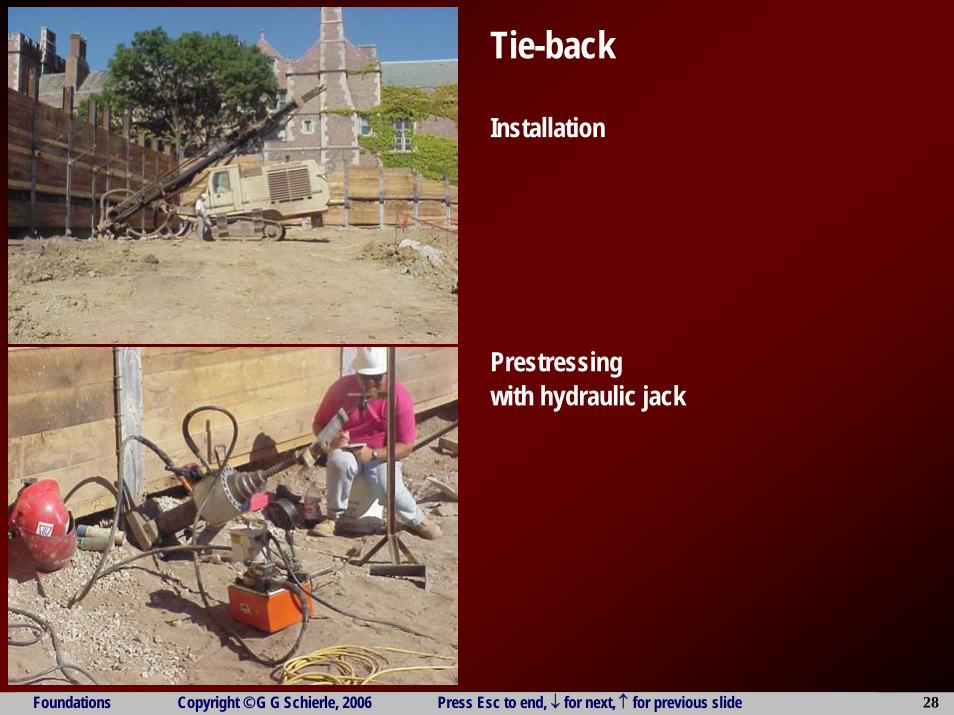
Tie-back
Installation
Prestressingwith hydraulic jack

Foundations Copyright © G G Schierle, 2006 Press Esc to end, ↓ for next, ↑ for previous slide 29
Slot cuttingUsed for retaining walls at property line
Slot cutting steps:
1 Cut slots in retaining slopes
2 Build retaining wall segments
3 Backfill retaining walls after about a week(backfill adds soil pressure)
4 Cut soil between wall segments
5 Construct infill retaining walls
Foundations Copyright © G G Schierle, 2006 Press Esc to end, ↓ for next, ↑ for previous slide 30
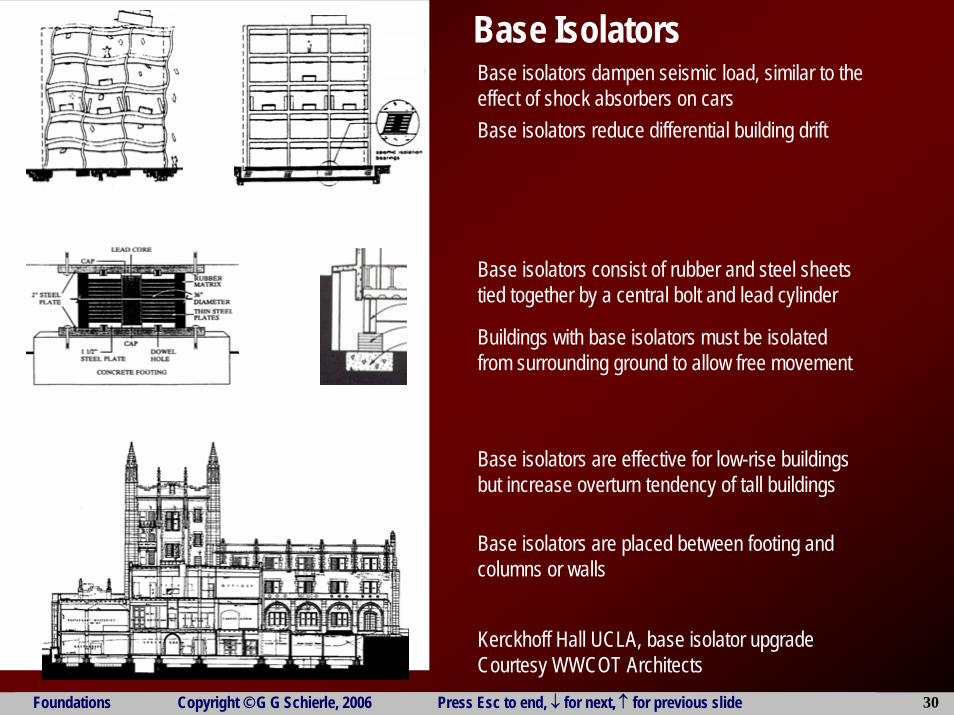
Base isolators dampen seismic load, similar to theeffect of shock absorbers on cars
Base Isolators
Base isolators reduce differential building drift
Base isolators consist of rubber and steel sheetstied together by a central bolt and lead cylinder
Buildings with base isolators must be isolatedfrom surrounding ground to allow free movement
Base isolators are effective for low-rise buildingsbut increase overturn tendency of tall buildings
Base isolators are placed between footing andcolumns or walls
Kerckhoff Hall UCLA, base isolator upgradeCourtesy WWCOT Architects
Foundations Copyright © G G Schierle, 2006 Press Esc to end, ↓ for next, ↑ for previous slide 31
ENDEND

Foundations Copyright © G G Schierle, 2006 Press Esc to end, ↓ for next, ↑ for previous slide 32
Exercise Name:__________________Assume: Concrete wall footingSoil capacity fs = 2000 psfFloor load (incl. walls) DL = 140 psf
LL = 50 psfRoof load (incl. walls) DL = 140 psf
LL = 20 psfTotal load Σ = 350 psf
Load on footingw = w = plfFooting DL estimatew=150 pcf (2’x1.5’) w = plfTotal loadw = w = plfRequired footing widthb = w/fs= Use b =____ft
20’
10’
10’