FOUNDATIONS AND RETAINING WALLS UPDATE...o Coulomb, δ= ⅔φ o Rankine, δ= β′ OGE Foundations...
118
FOUNDATIONS AND RETAINING WALLS UPDATE GEOTECHNICAL CONSULTANT WORKSHOP, JUNE 05 2018
Transcript of FOUNDATIONS AND RETAINING WALLS UPDATE...o Coulomb, δ= ⅔φ o Rankine, δ= β′ OGE Foundations...

FOUNDATIONS AND RETAINING WALLS UPDATEGEOTECHNICAL CONSULTANT WORKSHOP, JUNE 05 2018

2 |
FOUNDATIONS
AND RETAINING
WALLS UPDATEAlexander B.C. Dettloff, P.E.
State Foundations Engineer
ODOT Office of Geotechnical Engineering
OGE Foundations and Retaining Walls Update • June 05, 2018

3 |
AASHTO LRFD 8TH EDITION (2018)
o AASHTO LRFD Highlights
(Bigger Changes)
o AASHTO LRFD Specific Article
Changes
o Other Subjects for Discussion
OGE Foundations and Retaining Walls Update • June 05, 2018

4 |
AASHTO LRFD 8TH EDITION (2018)
o Highlights:o Section 5: Concrete Structures
o Completely New and Reorganized
o old 5.8.2.9 - Shear Stress in Concrete, is
now 5.7.2.8
o old 5.13.3 - Footings, is now 5.12.8
o old 5.13.4 - Concrete Piles, is now 5.12.9
o old 5.13.4.6 - Seismic Requirements,
moved to 5.11.3.2 and 5.11.4.5 under
new 5.11 - Seismic Design and Details
OGE Foundations and Retaining Walls Update • June 05, 2018

5 |
AASHTO LRFD 8TH EDITION (2018)
o Highlights:o Section 6: Steel Structures
o Many new changes (94 Articles)
o 6.5.4.2 - Resistance Factors: For axial
compression, steel only φc = 0.95
(2014, 7th Ed. change)
o Section 7: Aluminum Structures
o Also many changes (69 Articles)
OGE Foundations and Retaining Walls Update • June 05, 2018

6 |
AASHTO LRFD 8TH EDITION (2018)
o Highlights:o Coulomb Analysis of MSE Walls Ballot Item
o Formerly, Rankine with δ = β or B
o Now explicitly Coulomb, δ ≤ ⅔ ϕ
o “Horizontal” EH, LS, ES inclined at δ
o Affects the following Articles:
o 3.11.5.8.1 - Earth Pressure Distribution for
MSE Walls
o 11.10.5.2 – Loading
o 11.10.7.1 - External Stability (Seismic)
OGE Foundations and Retaining Walls Update • June 05, 2018

7 |
AASHTO LRFD 8TH EDITION (2018)
o Highlights:o Coulomb Analysis of MSE Walls Ballot Item
o Article 11.10.7.1 - External Stability
o Figure 11.10.7.1-1 updated to show PAE
inclined at Coulomb δ
OGE Foundations and Retaining Walls Update • June 05, 2018

8 |
AASHTO LRFD 8TH EDITION (2018)
o Highlights:o Coulomb Analysis of MSE Walls Ballot Item
o Article 3.11.5.8.1 - Earth Pressure
Distribution for MSE Walls
o For broken back slope use either:
o Generalized Limit Equilibrium (GLE)
Method (see A11.3.3),
o Coulomb Trial-Wedge Analysis (see
A11.3.1, A11.3.2), or
o “Traditional Method” per Figure C3.11.5.8.1-1 with β = β′
OGE Foundations and Retaining Walls Update • June 05, 2018

9 |
AASHTO LRFD 8TH EDITION (2018)
OGE Foundations and Retaining Walls Update • June 05, 2018

10 |
AASHTO LRFD 8TH EDITION (2018)
OGE Foundations and Retaining Walls Update • June 05, 2018

11 |
AASHTO LRFD 8TH EDITION (2018)
OGE Foundations and Retaining Walls Update • June 05, 2018

12 |
AASHTO LRFD 8TH EDITION (2018)
OGE Foundations and Retaining Walls Update • June 05, 2018

13 |
AASHTO LRFD 8TH EDITION (2018)
o “Traditional Method”o Coulomb, δ = ⅔ φ
o Rankine, δ = β′
OGE Foundations and Retaining Walls Update • June 05, 2018
Method of Calculation "Horizontal" Earth Pressure Load
Limit Equilibrium Analysis 45,738 lb/ft
Coulomb Trial-Wedge Analysis 46,072 lb/ft
Coulomb "Traditional" Method 52,734 lb/ft
Rankine "Traditional" Method 53,012 lb/ft

14 |
AASHTO LRFD 8TH EDITION (2018)
o Highlights:o Seismic Wall Corners Ballot Item
o No longer requires seismic analysis for
walls with changes in alignment
sharper than 120 degrees, but calls
attention to why these changes in
alignment are problematic:
OGE Foundations and Retaining Walls Update • June 05, 2018

15 |
AASHTO LRFD 8TH EDITION (2018)
o Highlights:o Seismic Wall Corners Ballot Item
o (they “tend to exhibit greater damage
than free standing walls with generally
straight alignments due to potentially
greater stiffness at the corner, or may
separate at the corner due to lack of
connectivity between wall sections at
the corner.”)
OGE Foundations and Retaining Walls Update • June 05, 2018
16 |
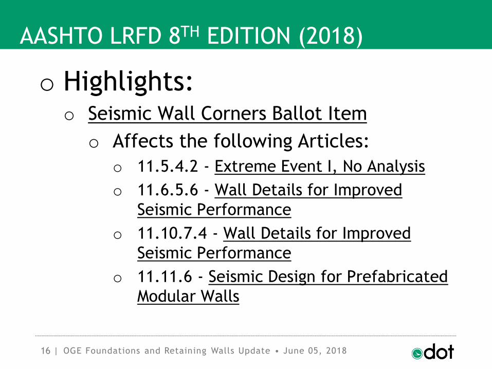
AASHTO LRFD 8TH EDITION (2018)
o Highlights:o Seismic Wall Corners Ballot Item
o Affects the following Articles:
o 11.5.4.2 - Extreme Event I, No Analysis
o 11.6.5.6 - Wall Details for Improved
Seismic Performance
o 11.10.7.4 - Wall Details for Improved
Seismic Performance
o 11.11.6 - Seismic Design for Prefabricated
Modular Walls
OGE Foundations and Retaining Walls Update • June 05, 2018

17 |
AASHTO LRFD 8TH EDITION (2018)
o Highlights:o Seismic Wall Corners Ballot Item
o Formerly no guidance provided on what
specific analyses should be conducted
to address the potentially higher loads,
nor is any such guidance available.
Therefore, these articles have been
refocused to provide better guidance
on what is expected for good seismic
detailing.
OGE Foundations and Retaining Walls Update • June 05, 2018

18 |
AASHTO LRFD 8TH EDITION (2018)
o Highlights:o Seismic Wall Corners Ballot Item
o Also calls attention to the fact that
placement and compaction of fill at
corners requires more attention than
other sections along the wall due to
lack of room there. Inadequate
compaction can potentially cause
increased deformations at the corners
during a seismic event.
OGE Foundations and Retaining Walls Update • June 05, 2018

19 |
AASHTO LRFD 8TH EDITION (2018)
o Specific Article Changes:o 3.8.1.2.1 - Wind Load on Structures: WS
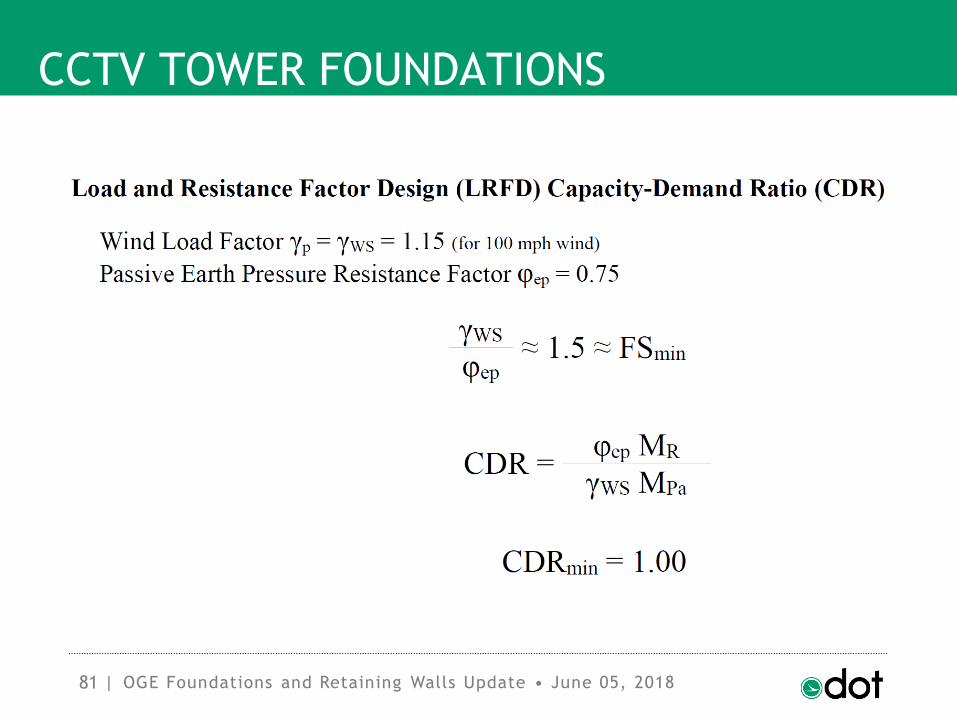
o For Ohio, Design Speed V = 115 mph
o Load Factor γWS = 1.00
o Generally, design pressure ≈ 0.07 ksf
o Formerly, V = 100 mph, γWS = 1.40
o Formerly, design pressure ≈ 0.05 ksf
o 1.40 × 0.05 = 0.07 (no change)
OGE Foundations and Retaining Walls Update • June 05, 2018

20 |
AASHTO LRFD 8TH EDITION (2018)
o Specific Article Changes:o 3.11.5.3 - Active Lateral Earth Pressure
Coefficient, ka
o δ = 0.67 ϕ soil-concrete, soil-soil
o δ = 0.33 ϕ soil-steel
o δ = 0.50 ϕ * soil-precast concrete
o δ = 0.70 ϕ * prefabricated modular
stepped modules
* per Table C3.11.5.9-1
OGE Foundations and Retaining Walls Update • June 05, 2018

21 |
AASHTO LRFD 8TH EDITION (2018)
OGE Foundations and Retaining Walls Update • June 05, 2018

22 |
AASHTO LRFD 8TH EDITION (2018)
o Specific Article Changes:o 3.11.5.6 - Lateral Earth Pressures for
Nongravity Cantilevered Walls
o For Figures 3.11.5.6-3, 3.11.5.6-6, and
3.11.5.6-7 (Teng, 1962) , D = 1.2 Do
o Explicitly states that adding 20% to
depth is due to a simplification of the
loading model.
OGE Foundations and Retaining Walls Update • June 05, 2018

23 |
AASHTO LRFD 8TH EDITION (2018)
OGE Foundations and Retaining Walls Update • June 05, 2018
24 |
AASHTO LRFD 8TH EDITION (2018)
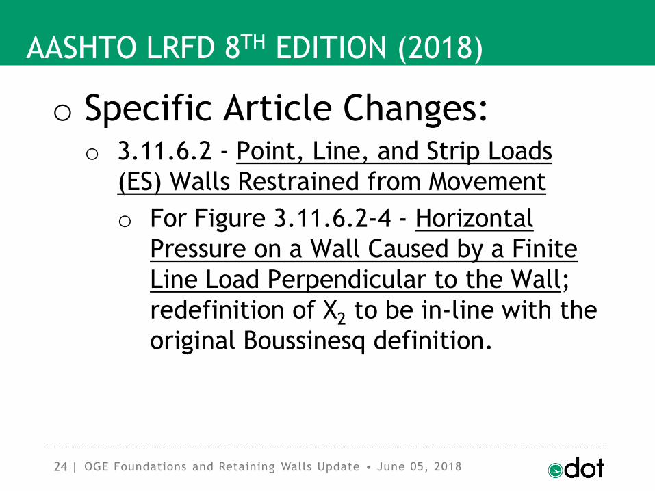
o Specific Article Changes:o 3.11.6.2 - Point, Line, and Strip Loads
(ES) Walls Restrained from Movement
o For Figure 3.11.6.2-4 - Horizontal
Pressure on a Wall Caused by a Finite
Line Load Perpendicular to the Wall;
redefinition of X2 to be in-line with the
original Boussinesq definition.
OGE Foundations and Retaining Walls Update • June 05, 2018

25 |
AASHTO LRFD 8TH EDITION (2018)
OGE Foundations and Retaining Walls Update • June 05, 2018

26 |
AASHTO LRFD 8TH EDITION (2018)
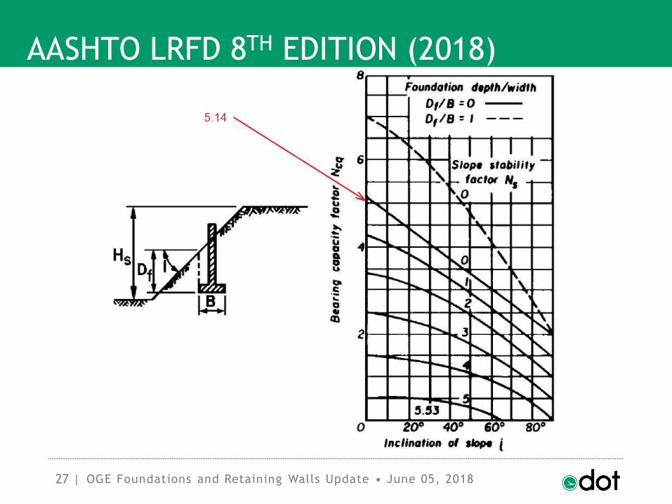
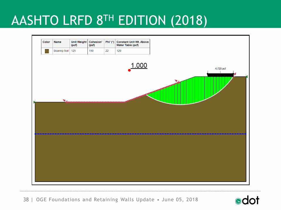
o Specific Article Changes:o 10.6.3.1.2c - Considerations for Footings
on Slopes
o Formerly no convergence of Nc
(to 5.14 or drained value for flat slope)
o Now use Tables for RCBC
o qn-sloping ground = RCBC qn
o or use Limit Equilibrium
OGE Foundations and Retaining Walls Update • June 05, 2018
27 |
AASHTO LRFD 8TH EDITION (2018)
OGE Foundations and Retaining Walls Update • June 05, 2018

28 |
AASHTO LRFD 8TH EDITION (2018)
OGE Foundations and Retaining Walls Update • June 05, 2018

29 |
AASHTO LRFD 8TH EDITION (2018)
OGE Foundations and Retaining Walls Update • June 05, 2018

30 |
AASHTO LRFD 8TH EDITION (2018)
OGE Foundations and Retaining Walls Update • June 05, 2018
31 |
AASHTO LRFD 8TH EDITION (2018)
OGE Foundations and Retaining Walls Update • June 05, 2018
32 |
AASHTO LRFD 8TH EDITION (2018)
OGE Foundations and Retaining Walls Update • June 05, 2018
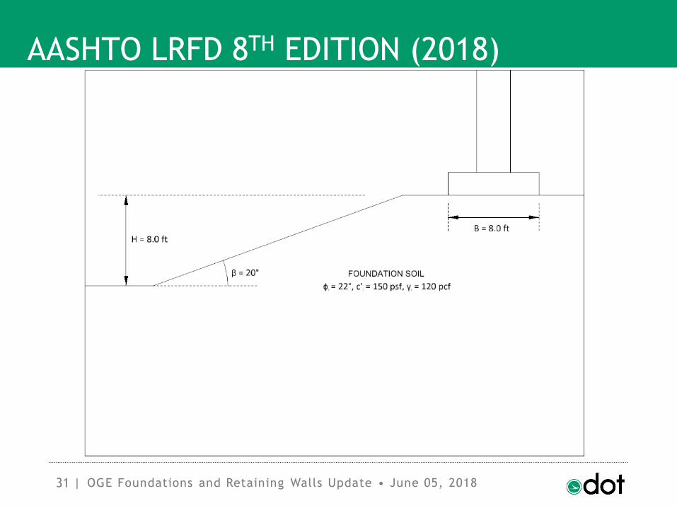
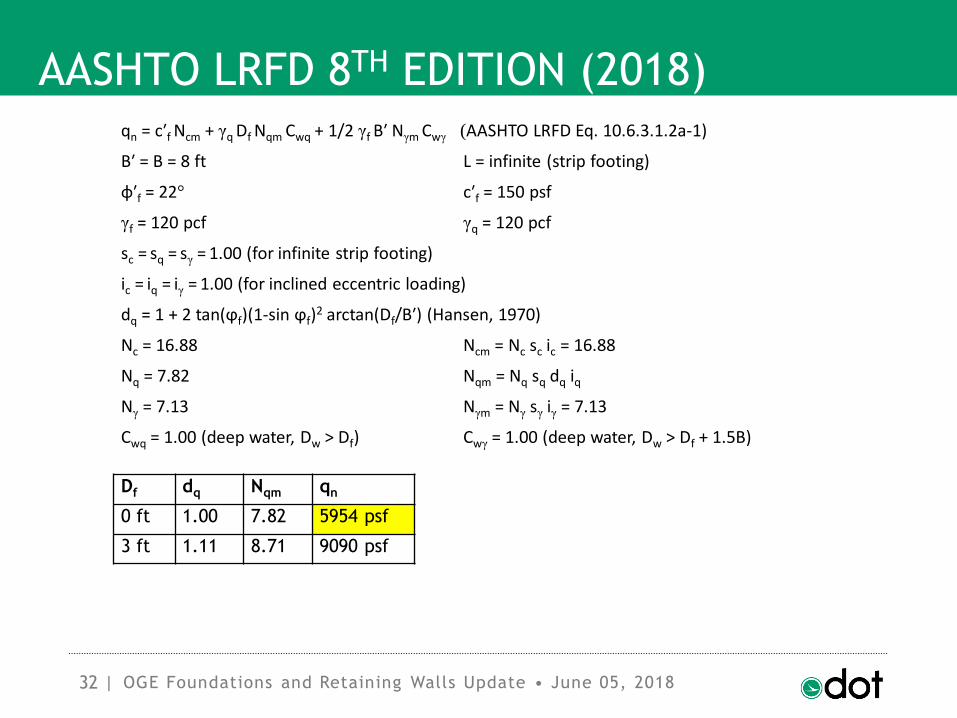
qn = c′f Ncm + γq Df Nqm Cwq + 1/2 γf B′ Nγm Cwγ (AASHTO LRFD Eq. 10.6.3.1.2a-1)
B′ = B = 8 ft L = infinite (strip footing)
φ′f = 22° c′f = 150 psf
γf = 120 pcf γq = 120 pcf
sc = sq = sγ = 1.00 (for infinite strip footing)
ic = iq = iγ = 1.00 (for inclined eccentric loading)
dq = 1 + 2 tan(ϕf)(1-sin ϕf)2 arctan(Df/B′) (Hansen, 1970)
Nc = 16.88 Ncm = Nc sc ic = 16.88
Nq = 7.82 Nqm = Nq sq dq iq
Nγ = 7.13 Nγm = Nγ sγ iγ = 7.13
Cwq = 1.00 (deep water, Dw > Df) Cwγ = 1.00 (deep water, Dw > Df + 1.5B)
Df dq Nqm qn
0 ft 1.00 7.82 5954 psf
3 ft 1.11 8.71 9090 psf

33 |
AASHTO LRFD 8TH EDITION (2018)
OGE Foundations and Retaining Walls Update • June 05, 2018
B/H = 1.0 1.0 1.0b/B = 0.5 0.5 0.5Ns = 6.4 4.0 4.0β = 20° 20° 20°φf = 22° 20° 30°RCBC = 0.78 0.79 0.74

34 |
AASHTO LRFD 8TH EDITION (2018)
OGE Foundations and Retaining Walls Update • June 05, 2018
qn-sloping ground = RCBC qn = 0.78 x 5954 psf = 4644 psf
Df dq Nqm qn qn-sloping ground
0 ft 1.00 7.82 5954 psf 4644 psf
3 ft 1.11 8.71 9090 psf N/A

35 |
AASHTO LRFD 8TH EDITION (2018)
OGE Foundations and Retaining Walls Update • June 05, 2018

36 |
AASHTO LRFD 8TH EDITION (2018)
OGE Foundations and Retaining Walls Update • June 05, 2018
37 |
AASHTO LRFD 8TH EDITION (2018)
OGE Foundations and Retaining Walls Update • June 05, 2018
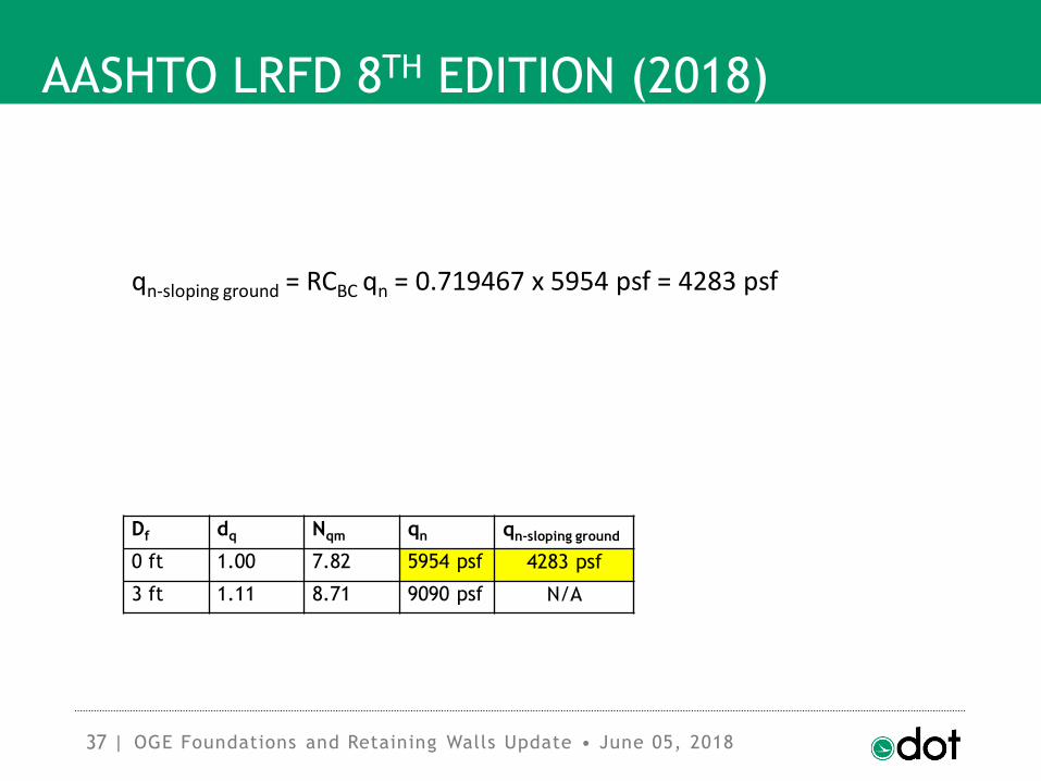
qn-sloping ground = RCBC qn = 0.719467 x 5954 psf = 4283 psf
Df dq Nqm qn qn-sloping ground
0 ft 1.00 7.82 5954 psf 4283 psf
3 ft 1.11 8.71 9090 psf N/A
38 |
AASHTO LRFD 8TH EDITION (2018)
OGE Foundations and Retaining Walls Update • June 05, 2018

39 |
AASHTO LRFD 8TH EDITION (2018)
OGE Foundations and Retaining Walls Update • June 05, 2018

40 |
AASHTO LRFD 8TH EDITION (2018)
OGE Foundations and Retaining Walls Update • June 05, 2018

41 |
AASHTO LRFD 8TH EDITION (2018)
Method Top of Slope Middle of Slope Flat Ground
RCBC Table 4644 78% 4283 72% 5954
Limit Equilibrium 4720 65% 4096 56% 7315
Percent Difference 2% 4% 23%
OGE Foundations and Retaining Walls Update • June 05, 2018

42 |
AASHTO LRFD 8TH EDITION (2018)
OGE Foundations and Retaining Walls Update • June 05, 2018

43 |
AASHTO LRFD 8TH EDITION (2018)
OGE Foundations and Retaining Walls Update • June 05, 2018

44 |
AASHTO LRFD 8TH EDITION (2018)
OGE Foundations and Retaining Walls Update • June 05, 2018

45 |
AASHTO LRFD 8TH EDITION (2018)
Method Top of Slope Middle of Slope Flat Ground
RCBC Table N/A N/A 9090
Limit Equilibrium 7404 71% 7869 75% 10500
Percent Difference N/A N/A 16%
OGE Foundations and Retaining Walls Update • June 05, 2018

46 |
AASHTO LRFD 8TH EDITION (2018)
o Specific Article Changes:o 10.6.3.4 - Failure by Sliding
o No more δ, replaced explicitly with ϕf.
o Now, Rτ = CV tan ϕf.
o C = 1.0 for CIP, C = 0.8 for precast
o For cohesive, rewrote so that footings
on clay are always on 6 in. granular
material, and 0.5 σ′v is not only a limit
when the granular material is present.
OGE Foundations and Retaining Walls Update • June 05, 2018

47 |
AASHTO LRFD 8TH EDITION (2018)
OGE Foundations and Retaining Walls Update • June 05, 2018

48 |
AASHTO LRFD 8TH EDITION (2018)
o Specific Article Changes:o 11.8.4.1 - Overall Stability
o Commentary states the design
procedure applied to Figure 3.11.5.6-3
(Teng, 1962) is for continuous walls
embedded in granular soils.
o States that similar procedures may also
be performed for temporary walls
using Figures 3.11.5.6-6 and 3.11.5.6-7
(Teng, 1962).
OGE Foundations and Retaining Walls Update • June 05, 2018

49 |
AASHTO LRFD 8TH EDITION (2018)
OGE Foundations and Retaining Walls Update • June 05, 2018

50 |
AASHTO LRFD 8TH EDITION (2018)
OGE Foundations and Retaining Walls Update • June 05, 2018

51 |
OTHER SUBJECTS FOR DISCUSSION
o Precast Wingwall Alternatives
o Prefabricated Modular Walls
o Predrilled Piles in Bedrock
o MSE Walls (various subjects)
o CCTV Tower Foundations
o Downdrag on Piles
OGE Foundations and Retaining Walls Update • June 05, 2018

52 |
OTHER SUBJECTS FOR DISCUSSION
o Settlement Time
o Spread Footing Foundations
in BDM versus L&D Manual
o Micropiles
o Monotube Piles
OGE Foundations and Retaining Walls Update • June 05, 2018
53 |
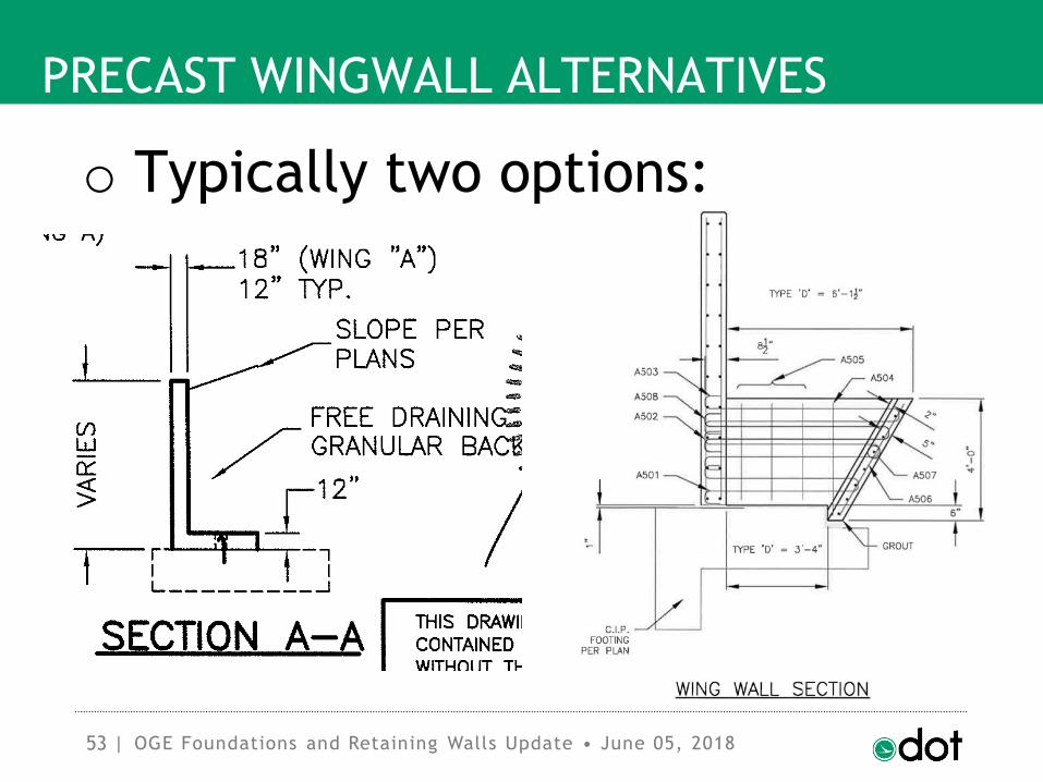
PRECAST WINGWALL ALTERNATIVES
o Typically two options:
OGE Foundations and Retaining Walls Update • June 05, 2018
54 |
PRECAST WINGWALL ALTERNATIVES
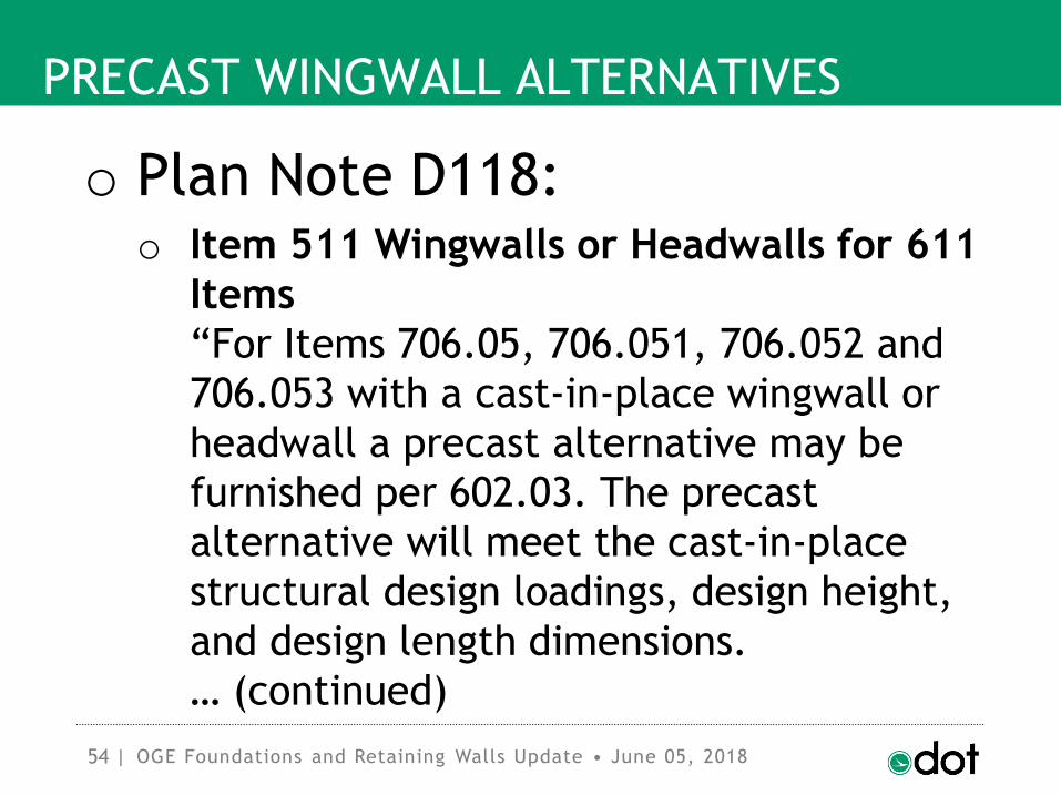
o Plan Note D118:o Item 511 Wingwalls or Headwalls for 611
Items
“For Items 706.05, 706.051, 706.052 and
706.053 with a cast-in-place wingwall or
headwall a precast alternative may be
furnished per 602.03. The precast
alternative will meet the cast-in-place
structural design loadings, design height,
and design length dimensions.
… (continued)
OGE Foundations and Retaining Walls Update • June 05, 2018

55 |
PRECAST WINGWALL ALTERNATIVES
o Plan Note D118:o Item 511 Wingwalls or Headwalls for 611
Items
…
Full compensation for the precast
wingwall or headwall is the number of
cubic yards of Item 511 and pounds of
Item 509 for the corresponding cast-in-
place structure.”
OGE Foundations and Retaining Walls Update • June 05, 2018

56 |
PRECAST WINGWALL ALTERNATIVES
o Plan Note D118 pulled and
revised:o No permanent tension on epoxy anchors
o Limit on angle between stream and walls
with no stem-footing moment connection
o Requirement of engineered drawings
including: backfill details, sequence of
construction, any changes to footing
o Payment quantity a lump sum
OGE Foundations and Retaining Walls Update • June 05, 2018

57 |
PRECAST WINGWALL ALTERNATIVES
o Precast Semigravity Wall
suppliers encouraged to submit
to Prefabricated Retaining Wall
Systems Approval Process.
o Pre-Approval will be required
within the next couple of
years.
OGE Foundations and Retaining Walls Update • June 05, 2018

58 |
PREFABRICATED MODULAR WALLS
o Prefabricated Modular Wall
Supplemental Specificationo Currently SS 840 provides design and
construction specification for MSE Walls
o Need new SS ### for Prefabricated
Modular Walls, to provide design and
construction specifications, so wall
systems can be submitted to the
Prefabricated Retaining Wall Systems
Approval Process on an even basis.
OGE Foundations and Retaining Walls Update • June 05, 2018

59 |
PREFABRICATED MODULAR WALLS
o Prefabricated Modular Wall
suppliers encouraged to submit
to Prefabricated Retaining Wall
Systems Approval Process.
o Pre-Approval will be required
within the next couple of
years.
OGE Foundations and Retaining Walls Update • June 05, 2018

60 |
PREFABRICATED MODULAR WALLS
o Prefabricated Modular Walls
Includeo Segmental (Modular Block) Walls
o (Dry-cast concrete modular systems will not
be allowed for highway construction)
o Large Gravity Block Walls
o Crib Walls
o Bin Walls
o Gabion Walls, per SS 838 (no preapproval)
OGE Foundations and Retaining Walls Update • June 05, 2018
61 |
PREDRILLED PILES IN BEDROCK
OGE Foundations and Retaining Walls Update • June 05, 2018

62 |
PREDRILLED PILES IN BEDROCK
o Predrill (pre-bore) hole to
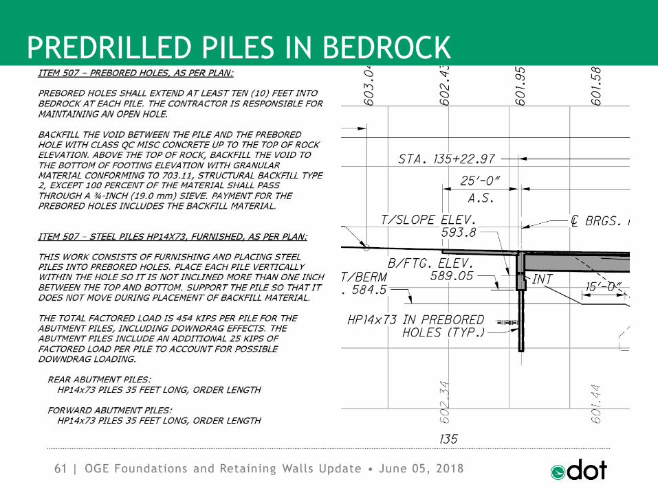
larger diameter than pileo Item 507 Prebored Holes, As Per Plan
o Place H-pile in holeo Item 507 Steel Piles HP__x__, Furnished
o Concrete Pile to Top of Rocko Use Class CQ Misc. Concrete
o Concrete included in Prebored Holes
OGE Foundations and Retaining Walls Update • June 05, 2018

63 |
PREDRILLED PILES IN BEDROCK
o Backfill to bottom of pile capo If MSE Wall, sleeve pile and use granular
fill per SS 840.03.K (include in MSE Wall)
o Otherwise:
o If conventional abutment, use LSM
o If integral abutment, use granular
o Backfill included in Prebored Holes Item
OGE Foundations and Retaining Walls Update • June 05, 2018
64 |
PREDRILLED PILES IN BEDROCK
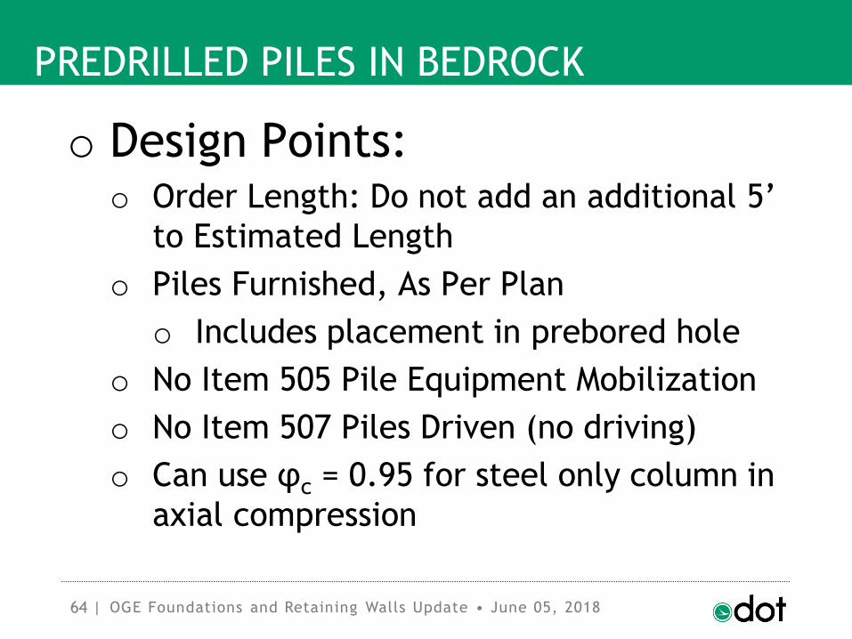
o Design Points:o Order Length: Do not add an additional 5’
to Estimated Length
o Piles Furnished, As Per Plan
o Includes placement in prebored hole
o No Item 505 Pile Equipment Mobilization
o No Item 507 Piles Driven (no driving)
o Can use φc = 0.95 for steel only column in
axial compression
OGE Foundations and Retaining Walls Update • June 05, 2018

65 |
MSE WALL DESIGN CONSIDERATIONS
o MSE Wallso Acute angle limits for temporary
construction
o Bearing elevation, sliding considerations
with granular undercut
o Two-stage construction
o Staged demolition: slope w/ short wire-
faced wall rather than tall wall
OGE Foundations and Retaining Walls Update • June 05, 2018

66 |
MSE WALL DESIGN CONSIDERATIONS
o Acute angle limits:o For permanent construction, no acute
corner angles (under 90°) allowed
o For temporary construction (wire-faced
MSE walls) acute angles to 45° allowed
o Acute angles must be buried or
demolished at end of construction
o If sharper acute angles are required for
MOT, then MSE walls cannot be utilized
OGE Foundations and Retaining Walls Update • June 05, 2018
67 |
MSE WALL DESIGN CONSIDERATIONS
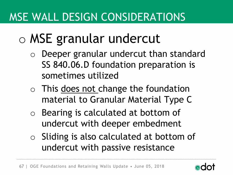
o MSE granular undercut o Deeper granular undercut than standard
SS 840.06.D foundation preparation is
sometimes utilized
o This does not change the foundation
material to Granular Material Type C
o Bearing is calculated at bottom of
undercut with deeper embedment
o Sliding is also calculated at bottom of
undercut with passive resistance
OGE Foundations and Retaining Walls Update • June 05, 2018

68 |
MSE WALL DESIGN CONSIDERATIONS
o MSE granular undercut
OGE Foundations and Retaining Walls Update • June 05, 2018

69 |
MSE WALL DESIGN CONSIDERATIONS
o Two-stage MSE Walls
OGE Foundations and Retaining Walls Update • June 05, 2018

70 |
MSE WALL DESIGN CONSIDERATIONS
o Two-stage MSE Walls
OGE Foundations and Retaining Walls Update • June 05, 2018

71 |
MSE WALL DESIGN CONSIDERATIONS
o Two-stage MSE Wallso Avoid galvanic corrosion (bimetallic
corrosion) in the connectors
o All metallic components hot-dip
galvanized or epoxy coated
o Avoid macrocell corrosion between
backfill and wall face
o Assure low chloride and sulfate content of
all wall backfill
o Provide drainage protection for connector
zone
OGE Foundations and Retaining Walls Update • June 05, 2018

72 |
MSE WALL DESIGN CONSIDERATIONS
o Staged bridge demolition
OGE Foundations and Retaining Walls Update • June 05, 2018

73 |
MSE WALL DESIGN CONSIDERATIONS
o Staged bridge demolition
OGE Foundations and Retaining Walls Update • June 05, 2018

74 |
CCTV TOWER FOUNDATIONS
o Office of Traffic Operationso Have installed numerous poles (several
hundred?) around the state over the last
several years
o CCTV Camera on top of 70-foot tall spun
precast concrete pole
o For camera stability, Serviceability
requirement of less than one inch
deflection at top of pole in 30 mph wind
OGE Foundations and Retaining Walls Update • June 05, 2018

75 |
CCTV TOWER FOUNDATIONS
o Service Limit State Controlso Still, check Strength Limit State at 100
mph wind
o Strength Limit State Design by Broms
Method, per “Design of Laterally Loaded
Piles” (Broms, 1965)
OGE Foundations and Retaining Walls Update • June 05, 2018

76 |
CCTV TOWER FOUNDATIONS
OGE Foundations and Retaining Walls Update • June 05, 2018

77 |
CCTV TOWER FOUNDATIONS
OGE Foundations and Retaining Walls Update • June 05, 2018

78 |
CCTV TOWER FOUNDATIONS
OGE Foundations and Retaining Walls Update • June 05, 2018

79 |
CCTV TOWER FOUNDATIONS
OGE Foundations and Retaining Walls Update • June 05, 2018

80 |
CCTV TOWER FOUNDATIONS
OGE Foundations and Retaining Walls Update • June 05, 2018
81 |
CCTV TOWER FOUNDATIONS
OGE Foundations and Retaining Walls Update • June 05, 2018

82 |
CCTV TOWER FOUNDATIONS
OGE Foundations and Retaining Walls Update • June 05, 2018

83 |
CCTV TOWER FOUNDATIONS
OGE Foundations and Retaining Walls Update • June 05, 2018
84 |
DOWNDRAG ON PILES
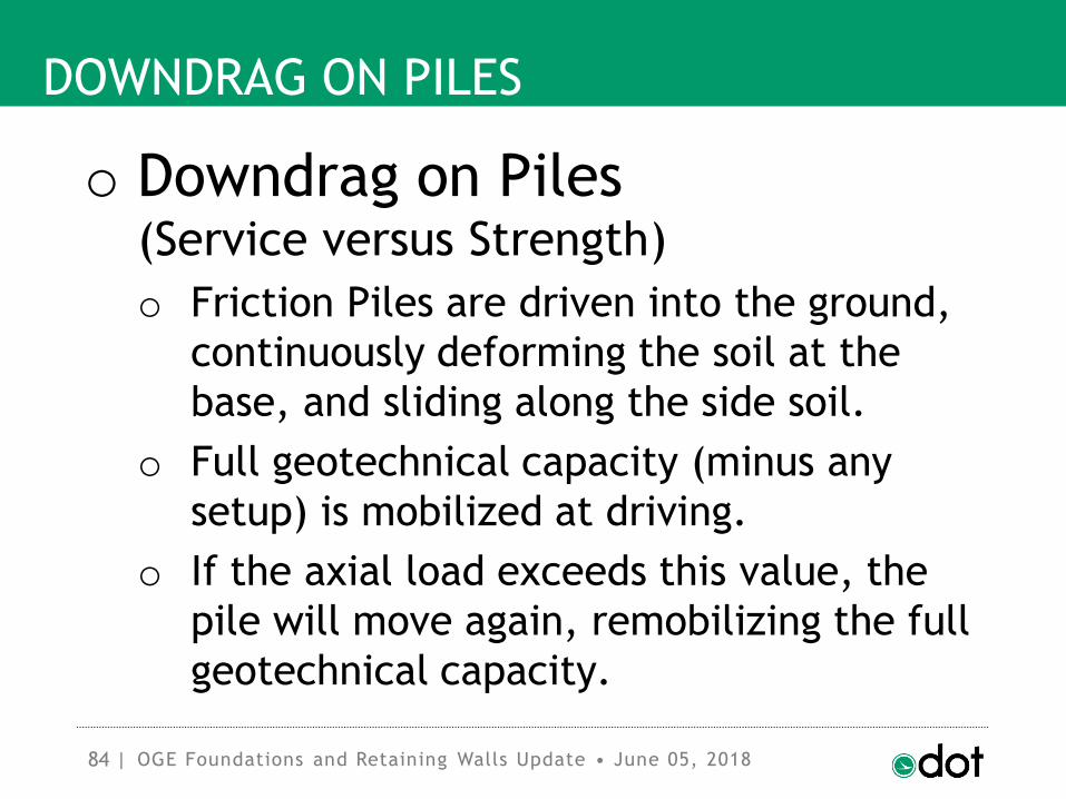
o Downdrag on Piles(Service versus Strength)
o Friction Piles are driven into the ground,
continuously deforming the soil at the
base, and sliding along the side soil.
o Full geotechnical capacity (minus any
setup) is mobilized at driving.
o If the axial load exceeds this value, the
pile will move again, remobilizing the full
geotechnical capacity.
OGE Foundations and Retaining Walls Update • June 05, 2018

85 |
DOWNDRAG ON PILES
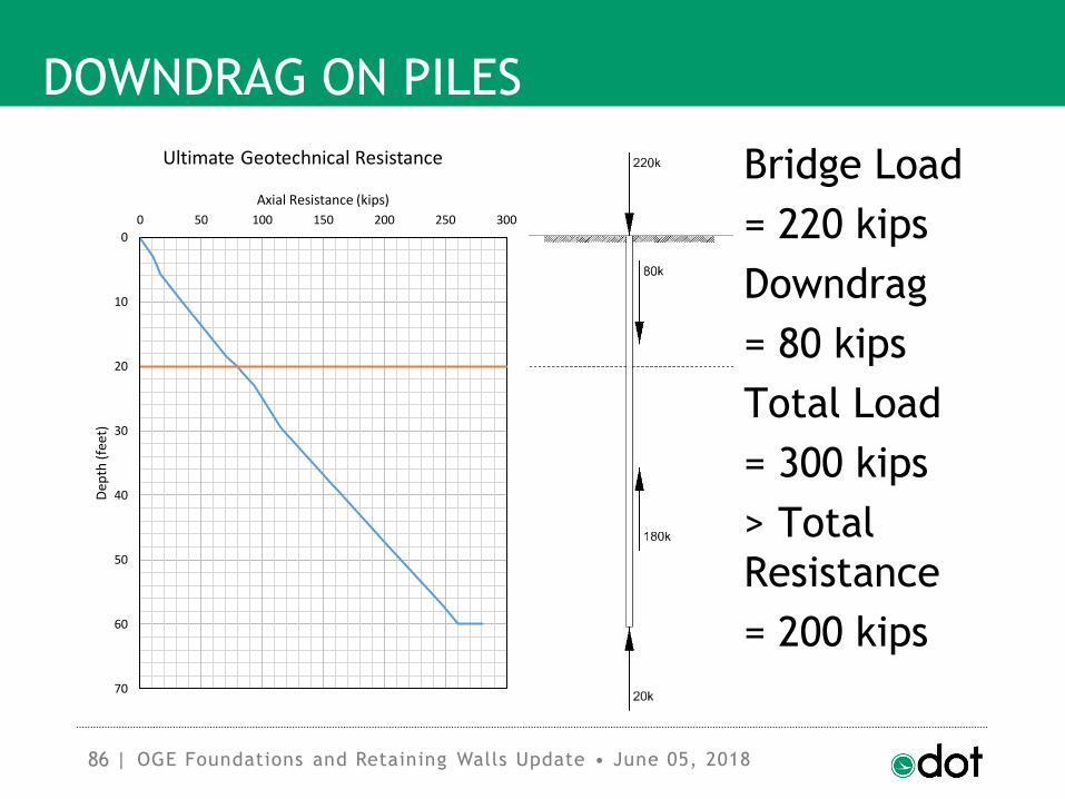
o Typical 12-inch CIP Pipe Pile,0.25” shell, 60 feet long, 35 ksi Steel
o 676.1 kips Nominal Axial Structural
Resistance
o Say, ultimate resistance is tip = 20 kips +
side = 260 kips = 280 kips total (geotech.)
o Say, settlement occurs in top 30 feet,
neutral plane at 20 feet.
o Friction in upper 20 feet = 80 kips
o Resistance below 20 feet = 200 kips
OGE Foundations and Retaining Walls Update • June 05, 2018
86 |
DOWNDRAG ON PILES
OGE Foundations and Retaining Walls Update • June 05, 2018
0
10
20
30
40
50
60
70
0 50 100 150 200 250 300
Dep
th (
feet
)
Axial Resistance (kips)
Ultimate Geotechnical Resistance Bridge Load
= 220 kips
Downdrag
= 80 kips
Total Load
= 300 kips
> Total
Resistance
= 200 kips

87 |
DOWNDRAG ON PILES
o Structural Resistance?o Total Load = 300 kips < 676.1 kips OK
o Geotechnical Resistance?o Total Load = 300 kips > 200 kips No Good
o But will the Pile Fail?o Depends on definition of “failure”
o Structurally, it is okay
o Geotechnically, it will move
(Service Limit State)OGE Foundations and Retaining Walls Update • June 05, 2018

88 |
DOWNDRAG ON PILES
OGE Foundations and Retaining Walls Update • June 05, 2018
0
10
20
30
40
50
60
70
0 50 100 150 200 250 300
Dep
th (
feet
)
Axial Resistance (kips)
Ultimate Geotechnical Resistance Bridge Load
= 220 kips
Downdrag
= 80 kips
Total Load
= 300 kips
> Total
Resistance
= 200 kips

89 |
DOWNDRAG ON PILES
OGE Foundations and Retaining Walls Update • June 05, 2018
Bridge Load
= 220 kips
Downdrag
= 30 kips
Total Load
= 250 kips
= Total
Resistance
= 250 kips
0
10
20
30
40
50
60
70
0 50 100 150 200 250 300
Dep
th (
feet
)
Axial Resistance (kips)
Ultimate Geotechnical Resistance
90 |
DOWNDRAG ON PILES
o Pile will stop moving when
neutral plane climbs to point
where:
bridge load + downdrag load =
total resistance
o Pile only needs to move a small
distance for this to happen
(around 1 cm = 0.4 inch)OGE Foundations and Retaining Walls Update • June 05, 2018

91 |
DOWNDRAG ON PILES
o Total Pile settlement will be
settlement of soil below
neutral plane + ≈0.4 inch
o This is a Service Limit issue
o See Amal Goza at OTEC 2018o See GEC 12 FHWA-NHI-16-009
o See MnDOT Geotechnical Manual
OGE Foundations and Retaining Walls Update • June 05, 2018

92 |
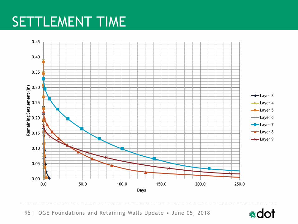
SETTLEMENT TIME
o Settlement Time:o A profile of settling soil is typically
divided into multiple layers with differing
consolidation characteristics:
o layer thickness
o overburden pressure
o maximum past pressure (OCR, virgin)
o drainage paths
o cc, cr, C′, cv (magnitude and rate)
OGE Foundations and Retaining Walls Update • June 05, 2018

93 |
SETTLEMENT TIME
o Some layers will take a long time to
consolidate, and some will do so nearly
immediately.
o The slowest layer does not control the
time to achieve consolidation (waiting
period), i.e. 90% or 0.4” remaining.
o Consider all layers individually, and then
build a composite of behavior.
o Consider the following 50-foot profile:
OGE Foundations and Retaining Walls Update • June 05, 2018

94 |
SETTLEMENT TIME
OGE Foundations and Retaining Walls Update • June 05, 2018
95 |
SETTLEMENT TIME
OGE Foundations and Retaining Walls Update • June 05, 2018
0.00
0.05
0.10
0.15
0.20
0.25
0.30
0.35
0.40
0.45
0.0 50.0 100.0 150.0 200.0 250.0
Rem
ain
ing S
ett
lem
ent
(in)
Days
Layer 3
Layer 4
Layer 5
Layer 6
Layer 7
Layer 8
Layer 9

96 |
SETTLEMENT TIME
OGE Foundations and Retaining Walls Update • June 05, 2018
0.00
0.05
0.10
0.15
0.20
0.25
0.30
0.35
0.0 50.0 100.0 150.0 200.0 250.0
Rem
ain
ing S
ett
lem
ent
(in)
Days
Layer 3
Layer 7
Layer 8
Layer 9

97 |
SETTLEMENT TIME
o Determine the amount of settlement
completed and remaining for each layer
at specific time intervals.
o At each time interval, sum the settlement
completed and remaining for all layers,
and plot this result versus time.
o Determine the T90 time for the entire soil
profile.
OGE Foundations and Retaining Walls Update • June 05, 2018

98 |
SETTLEMENT TIME
o If the total settlement remaining at the
T90 time is greater than 0.4 inches, then
use the T90 time for the waiting period,
rounding up to an even interval of
days/weeks/months.
o If the total settlement remaining at the
T90 time is less than 0.4 inches, then find
the time at which 0.4 inches remains, and
use this time for the waiting period, once
again rounding up to an even interval of
days/weeks/months.
OGE Foundations and Retaining Walls Update • June 05, 2018

99 |
SETTLEMENT TIME
OGE Foundations and Retaining Walls Update • June 05, 2018
0.00
0.20
0.40
0.60
0.80
1.00
1.20
1.40
1.60
1.80
2.00
0 5 10 15 20 25 30 35 40 45 50
Rem
ain
ing S
ett
lem
ent
(in)
Days
All Layers
All Layers
100 |
BDM VS L&D MANUAL: SPREAD FOOTINGS
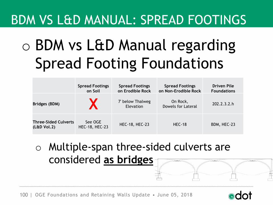
o BDM vs L&D Manual regarding
Spread Footing Foundations
o Multiple-span three-sided culverts are
considered as bridges
OGE Foundations and Retaining Walls Update • June 05, 2018
Spread Footings
on Soil
Spread Footings
on Erodible Rock
Spread Footings
on Non-Erodible Rock
Driven Pile
Foundations
Bridges (BDM) X 7' below ThalwegElevation
On Rock,Dowels for Lateral
202.2.3.2.h
Three-Sided Culverts (L&D Vol.2)
See OGEHEC-18, HEC-23
HEC-18, HEC-23 HEC-18 BDM, HEC-23

101 |
BDM VS L&D MANUAL: SPREAD FOOTINGS
o BDM Spread Footings on Rocko BDM Section 202.2.3.1.b is strict on
scour resistant (non-erodible) rock:
o Qu ≥ 2,500 psi (“slightly strong” rock)
o Remain intact when immersed in water
(e.g. insoluble) no bucket slaking
o Unit weight ≥ 150 pcf
o Joint or bedding plane spacing that
define large blocks (> 4-ft)
OGE Foundations and Retaining Walls Update • June 05, 2018

102 |
BDM VS L&D MANUAL: SPREAD FOOTINGS
o BDM Spread Footings on Rocko BDM Section 202.2.3.1.b eliminates nearly
all rock in Ohio as non-erodible
o We propose to change the erodibility
requirements to HEC-18, FHWA-HIF-12-003
o Erodibility Index for strong and durable
rocks (Quarrying and Plucking)
o Abrasion Scour of rock due to bedload
o We still need to define the use of these
for Ohio
OGE Foundations and Retaining Walls Update • June 05, 2018

103 |
BDM VS L&D MANUAL: SPREAD FOOTINGS
o HEC-18 Scour of Soilso Granular Soils: τc (Pa) = D50 (mm)
o Holds down to D50 ≈ 0.1 mm
OGE Foundations and Retaining Walls Update • June 05, 2018

104 |
BDM VS L&D MANUAL: SPREAD FOOTINGS
o HEC-18 Scour of Soilso Cohesive Soils not so straightforward
OGE Foundations and Retaining Walls Update • June 05, 2018
105 |
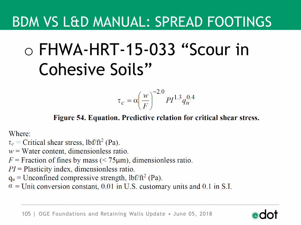
BDM VS L&D MANUAL: SPREAD FOOTINGS
o FHWA-HRT-15-033 “Scour in
Cohesive Soils”
OGE Foundations and Retaining Walls Update • June 05, 2018

106 |
BDM VS L&D MANUAL: SPREAD FOOTINGS
o Erosion Rate (Briaud, 2011)
OGE Foundations and Retaining Walls Update • June 05, 2018

107 |
BDM VS L&D MANUAL: SPREAD FOOTINGS
o Erosion Rate (Briaud, 2011)
OGE Foundations and Retaining Walls Update • June 05, 2018

108 |
BDM VS L&D MANUAL: SPREAD FOOTINGS
o Erosion Rate (Briaud, 2011)
OGE Foundations and Retaining Walls Update • June 05, 2018

109 |
BDM VS L&D MANUAL: SPREAD FOOTINGS
OGE Foundations and Retaining Walls Update • June 05, 2018

110 |
BDM VS L&D MANUAL: SPREAD FOOTINGS
o HEC-23, FHWA-NHI-09-112,
Bridge Scour and Stream
Instability Countermeasures
OGE Foundations and Retaining Walls Update • June 05, 2018

111 |
MICROPILES
o Micropileso Typically used for:
o Underpinning Inadequate Foundations
o Supplementing Existing Foundations
o Adding Lateral Stability
o Tight Overhead Working Conditions
o Generally not a cost-effective new-build
foundation option
OGE Foundations and Retaining Walls Update • June 05, 2018

112 |
MICROPILES
o Design Micropiles per:o AASHTO LRFD Bridge Design Specifications
Article 10.9 (LRFD)
o and AASHTO LRFD Bridge Construction
Specifications Section 33 (LRFD)
o or FHWA-NHI-05-039 “Micropile Design
and Construction Reference Manual”
(ASD)
OGE Foundations and Retaining Walls Update • June 05, 2018

113 |
MONOTUBE PILES
OGE Foundations and Retaining Walls Update • June 05, 2018

114 |
MONOTUBE PILES
o Monotube Pileso Monotube Pile Corporation out of business
o Removing vertical fluting, circumferential
corrugations, and tapered piles (B,C,D)
from 507.06
o No more replacement of CIP Pipe piles
with different types in construction
o No way to track these replacements, and
evidence shows they do not necessarily
perform the same (open to claims)
OGE Foundations and Retaining Walls Update • June 05, 2018

115 |
MONOTUBE PILES
o Miscellaneous Pileso We rarely (if ever) use the piles being
removed from 507.06
o However, future plan is to add a section
to C&MS 507 for Miscellaneous Piles,
including: Timber, Tapered, Fluted,
Corrugated, and Precast Concrete
o For now, these pile types can still be
specified under 507E98000 PILING, MISC.:
with appropriate plan notes
OGE Foundations and Retaining Walls Update • June 05, 2018

116 |
MONOTUBE PILES
o DRIVEN Monotube Pile modelo Allows negative cumulative side friction
(physically not possible)
o Slight Taper does not approach behavior
of straight pile
o Magnifies granular side frictional effects
in the taper length approximately 2.25x
o Often underpredicts length substantially
o ODOT will disallow use of this analysis
model for design
OGE Foundations and Retaining Walls Update • June 05, 2018

117 |
MONOTUBE PILES
o Monotube Pile analysiso Analyze as standard CIP Pipe Pile at
diameter of straight (non-tapered) part
o Add an additional 5 feet to Estimated
Length (beyond CIP Pipe Estimated)
o Ensure tapered length starts a minimum
of 5 feet below ground surface or pile cap
o Monotubes are fluted tapered piles, but
this also applies to smooth tapered piles
o Does not apply to Raymond tapered piles
OGE Foundations and Retaining Walls Update • June 05, 2018

118 |
?
QUESTIONS
Last updated 6/15/2018
OGE Foundations and Retaining Walls Update • June 05, 2018