Foundation® Total Knee - Amazon Web Services · Foundation® Total Knee 1 ... The Foundation...
14
Surgical Technique Foundation® Total Knee TM
Transcript of Foundation® Total Knee - Amazon Web Services · Foundation® Total Knee 1 ... The Foundation...

Surgical Technique
Foundation® Total Knee
TM
This brochure is presented to demonstrate the surgical technique utilized by the surgeons listed above. DJO Surgical, as the manufacturer of this device, does not practice medicine and cannot recommend this or any other surgical technique for use on a specific patient. The choice of the appropriate surgical technique is the responsibility of the surgeon performing the operation.
Surgical TechniqueFoundation® Total Knee
1
Contributing SurgeonGary M. Ferguson, M.D. Clinical Assistant Professor Brown University Providence, RI
Richard J. Friedman, M.D., FRCS(C) Professor of Orthopaedic Surgery Medical University of South Carolina Charleston, SC
Joseph Longo, MD Clinical Instructor Phoenix Orthopaedic Residency Training Program VA Medical Center Phoenix, AZ
DJO Surgical9800 Metric BoulevardAustin, TX
(800) 456-8696www.djosurgical.com
Table of Contents
Design Rationale 2Preoperative Planning 8Surgical Technique 10
Femoral Preparation 10Tibial Preparation 14
Component Implantation 18Wound Closure 22Cruciate Sacrificing P.S. 23
Surgical TechniqueFoundation® Total Knee
32
Design RationaleFoundation® Total Knee
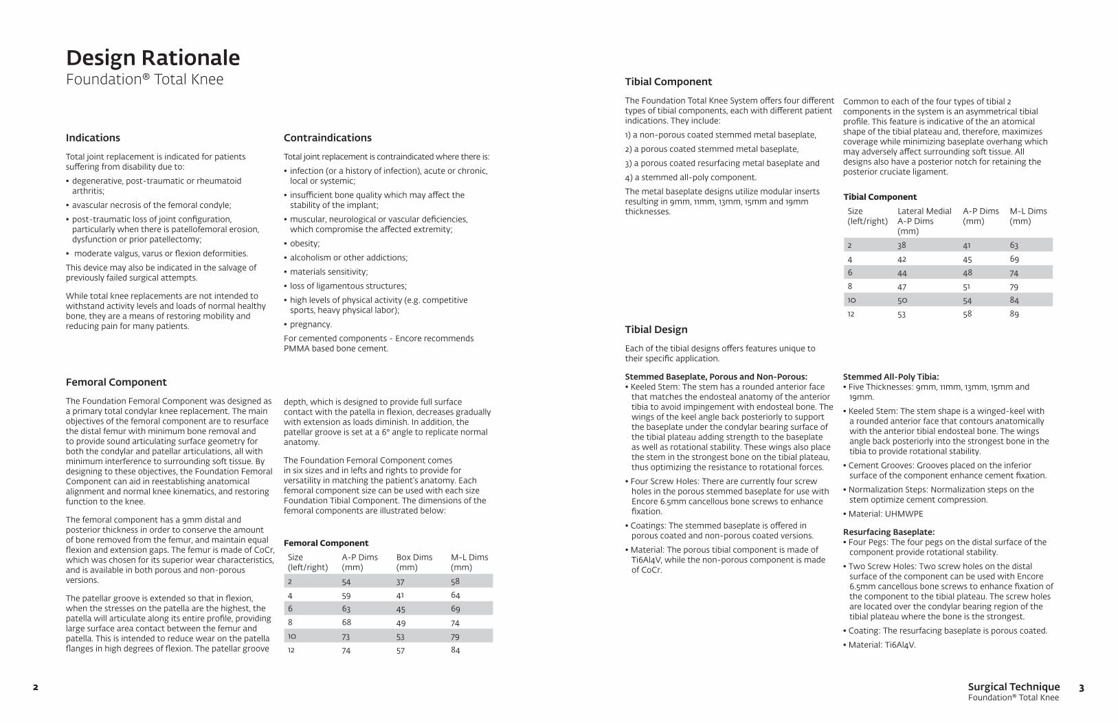
Femoral Component Size (left/right)
A-P Dims (mm)
Box Dims (mm)
M-L Dims (mm)
2 54 37 58
4 59 41 64
6 63 45 69
8 68 49 74
10 73 53 79
12 74 57 84
Femoral Component
The Foundation Femoral Component was designed as a primary total condylar knee replacement. The main objectives of the femoral component are to resurface the distal femur with minimum bone removal and to provide sound articulating surface geometry for both the condylar and patellar articulations, all with minimum interference to surrounding soft tissue. By designing to these objectives, the Foundation Femoral Component can aid in reestablishing anatomical alignment and normal knee kinematics, and restoring function to the knee.
The femoral component has a 9mm distal and posterior thickness in order to conserve the amount of bone removed from the femur, and maintain equal flexion and extension gaps. The femur is made of CoCr, which was chosen for its superior wear characteristics, and is available in both porous and non-porous versions.
The patellar groove is extended so that in flexion, when the stresses on the patella are the highest, the patella will articulate along its entire profile, providing large surface area contact between the femur and patella. This is intended to reduce wear on the patella flanges in high degrees of flexion. The patellar groove
Indications
Total joint replacement is indicated for patients suffering from disability due to:
•degenerative,post-traumaticorrheumatoidarthritis;
•avascularnecrosisofthefemoralcondyle;
•post-traumaticlossofjointconfiguration,particularly when there is patellofemoral erosion, dysfunction or prior patellectomy;
• moderatevalgus,varusorflexiondeformities.
This device may also be indicated in the salvage of previously failed surgical attempts.
While total knee replacements are not intended to withstand activity levels and loads of normal healthy bone, they are a means of restoring mobility and reducing pain for many patients.
Tibial Component
The Foundation Total Knee System offers four different types of tibial components, each with different patient indications. They include:
1) a non-porous coated stemmed metal baseplate,
2) a porous coated stemmed metal baseplate,
3) a porous coated resurfacing metal baseplate and
4) a stemmed all-poly component.
The metal baseplate designs utilize modular inserts resulting in 9mm, 11mm, 13mm, 15mm and 19mm thicknesses.
Tibial Design
Each of the tibial designs offers features unique to their specific application.
Stemmed Baseplate, Porous and Non-Porous: •KeeledStem:Thestemhasaroundedanteriorface
that matches the endosteal anatomy of the anterior tibia to avoid impingement with endosteal bone. The wings of the keel angle back posteriorly to support the baseplate under the condylar bearing surface of the tibial plateau adding strength to the baseplate as well as rotational stability. These wings also place the stem in the strongest bone on the tibial plateau, thus optimizing the resistance to rotational forces.
•FourScrewHoles:Therearecurrentlyfourscrewholes in the porous stemmed baseplate for use with Encore 6.5mm cancellous bone screws to enhance fixation.
•Coatings:Thestemmedbaseplateisofferedinporous coated and non-porous coated versions.
•Material:TheporoustibialcomponentismadeofTi6Al4V, while the non-porous component is made of CoCr.
Tibial Component Size (left/right)
Lateral Medial A-P Dims (mm)
A-P Dims (mm)
M-L Dims (mm)
2 38 41 63
4 42 45 69
6 44 48 74
8 47 51 79
10 50 54 84
12 53 58 89
Contraindications
Total joint replacement is contraindicated where there is:
• infection(orahistoryofinfection),acuteorchronic,local or systemic;
• insufficientbonequalitywhichmayaffectthestability of the implant;
•muscular,neurologicalorvasculardeficiencies, which compromise the affected extremity;
•obesity;
•alcoholismorotheraddictions;
•materialssensitivity;
• lossofligamentousstructures;
•highlevelsofphysicalactivity(e.g.competitivesports, heavy physical labor);
•pregnancy.
For cemented components - Encore recommends PMMA based bone cement.
depth, which is designed to provide full surface contact with the patella in flexion, decreases gradually with extension as loads diminish. In addition, the patellar groove is set at a 6° angle to replicate normal anatomy.
The Foundation Femoral Component comes in six sizes and in lefts and rights to provide for versatility in matching the patient’s anatomy. Each femoral component size can be used with each size Foundation Tibial Component. The dimensions of the femoral components are illustrated below:
Stemmed All-Poly Tibia:•FiveThicknesses:9mm,11mm,13mm,15mmand
19mm.
•KeeledStem:Thestemshapeisawinged-keelwitha rounded anterior face that contours anatomically with the anterior tibial endosteal bone. The wings angle back posteriorly into the strongest bone in the tibia to provide rotational stability.
•CementGrooves:Groovesplacedontheinferiorsurface of the component enhance cement fixation.
•NormalizationSteps:Normalizationstepsonthestem optimize cement compression.
•Material:UHMWPE
Resurfacing Baseplate:•FourPegs:Thefourpegsonthedistalsurfaceofthe
component provide rotational stability.
•TwoScrewHoles:Twoscrewholesonthedistalsurface of the component can be used with Encore 6.5mm cancellous bone screws to enhance fixation of the component to the tibial plateau. The screw holes are located over the condylar bearing region of the tibial plateau where the bone is the strongest.
•Coating:Theresurfacingbaseplateisporouscoated.
•Material:Ti6Al4V.
Common to each of the four types of tibial 2 components in the system is an asymmetrical tibial profile. This feature is indicative of the an atomical shape of the tibial plateau and, therefore, maximizes coverage while minimizing baseplate overhang which may adversely affect surrounding soft tissue. All designs also have a posterior notch for retaining the posterior cruciate ligament.
Surgical TechniqueFoundation® Total Knee
54
Design RationaleFoundation® Total Knee
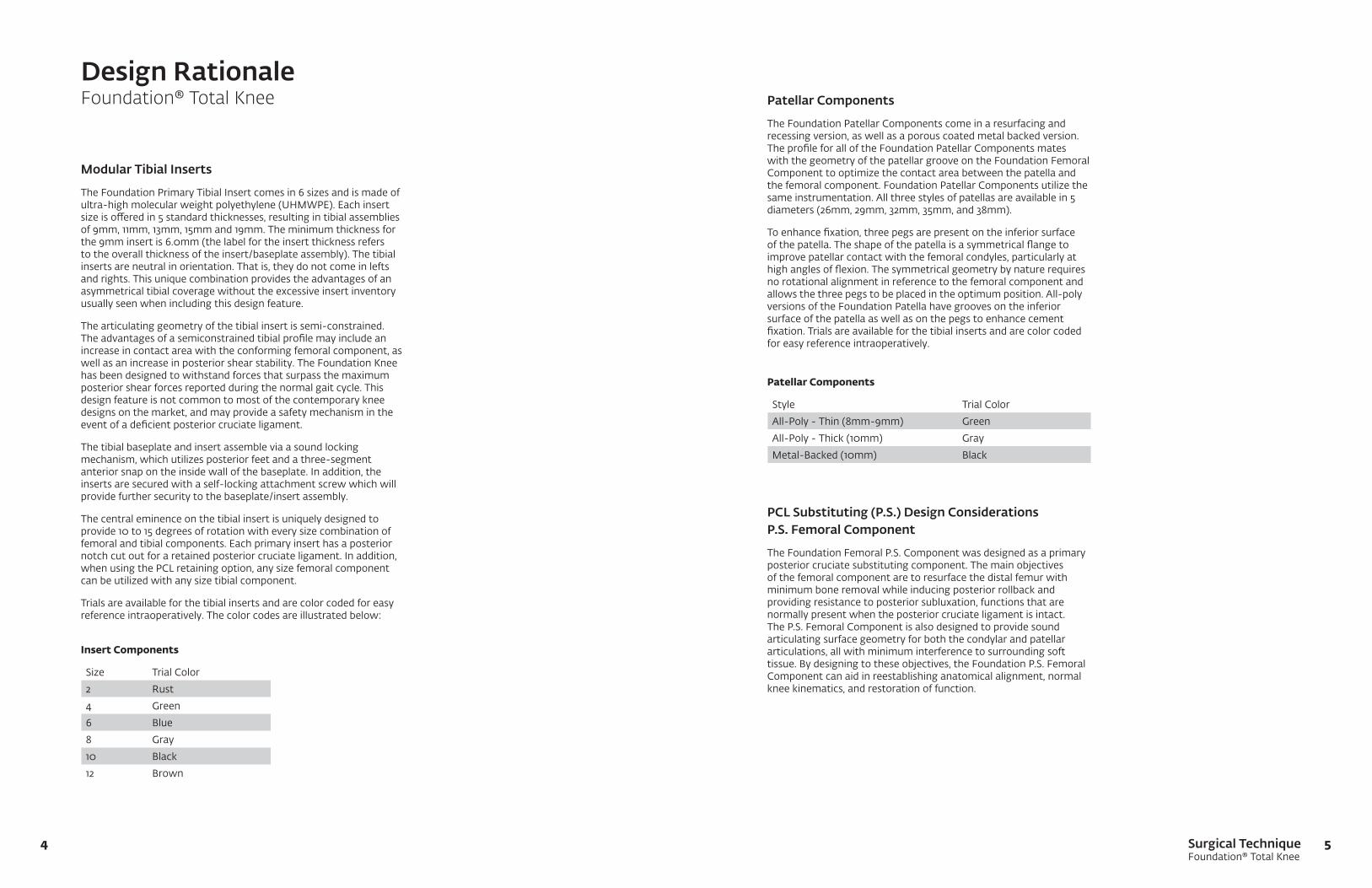
Modular Tibial Inserts
The Foundation Primary Tibial Insert comes in 6 sizes and is made of ultra-highmolecularweightpolyethylene(UHMWPE).Eachinsertsize is offered in 5 standard thicknesses, resulting in tibial assemblies of 9mm, 11mm, 13mm, 15mm and 19mm. The minimum thickness for the 9mm insert is 6.0mm (the label for the insert thickness refers to the overall thickness of the insert/baseplate assembly). The tibial inserts are neutral in orientation. That is, they do not come in lefts and rights. This unique combination provides the advantages of an asymmetrical tibial coverage without the excessive insert inventory usually seen when including this design feature.
The articulating geometry of the tibial insert is semi-constrained. The advantages of a semiconstrained tibial profile may include an increase in contact area with the conforming femoral component, as well as an increase in posterior shear stability. The Foundation Knee has been designed to withstand forces that surpass the maximum posterior shear forces reported during the normal gait cycle. This design feature is not common to most of the contemporary knee designs on the market, and may provide a safety mechanism in the event of a deficient posterior cruciate ligament.
The tibial baseplate and insert assemble via a sound locking mechanism, which utilizes posterior feet and a three-segment anterior snap on the inside wall of the baseplate. In addition, the inserts are secured with a self-locking attachment screw which will provide further security to the baseplate/insert assembly.
The central eminence on the tibial insert is uniquely designed to provide 10 to 15 degrees of rotation with every size combination of femoral and tibial components. Each primary insert has a posterior notch cut out for a retained posterior cruciate ligament. In addition, when using the PCL retaining option, any size femoral component can be utilized with any size tibial component.
Trials are available for the tibial inserts and are color coded for easy reference intraoperatively. The color codes are illustrated below:
Insert Components
Size Trial Color
2 Rust
4 Green
6 Blue
8 Gray
10 Black
12 Brown
Patellar Components
The Foundation Patellar Components come in a resurfacing and recessing version, as well as a porous coated metal backed version. The profile for all of the Foundation Patellar Components mates with the geometry of the patellar groove on the Foundation Femoral Component to optimize the contact area between the patella and the femoral component. Foundation Patellar Components utilize the same instrumentation. All three styles of patellas are available in 5 diameters (26mm, 29mm, 32mm, 35mm, and 38mm).
To enhance fixation, three pegs are present on the inferior surface of the patella. The shape of the patella is a symmetrical flange to improve patellar contact with the femoral condyles, particularly at high angles of flexion. The symmetrical geometry by nature requires no rotational alignment in reference to the femoral component and allows the three pegs to be placed in the optimum position. All-poly versions of the Foundation Patella have grooves on the inferior surface of the patella as well as on the pegs to enhance cement fixation. Trials are available for the tibial inserts and are color coded for easy reference intraoperatively.
PCL Substituting (P.S.) Design Considerations P.S. Femoral Component
The Foundation Femoral P.S. Component was designed as a primary posterior cruciate substituting component. The main objectives of the femoral component are to resurface the distal femur with minimum bone removal while inducing posterior rollback and providing resistance to posterior subluxation, functions that are normally present when the posterior cruciate ligament is intact. The P.S. Femoral Component is also designed to provide sound articulating surface geometry for both the condylar and patellar articulations, all with minimum interference to surrounding soft tissue. By designing to these objectives, the Foundation P.S. Femoral Component can aid in reestablishing anatomical alignment, normal knee kinematics, and restoration of function.
Patellar Components
Style Trial Color
All-Poly - Thin (8mm-9mm) Green
All-Poly - Thick (10mm) Gray
Metal-Backed (10mm) Black

Surgical TechniqueFoundation® Total Knee
76
Design RationaleFoundation® Total Knee
P.S. Femoral Component
The distal and posterior thicknesses of the femoral component are each 9mm. This thickness was chosen to conserve the amount of bone removed from the femur and to ensure that the flexion and extension gaps remain equal. The femoral component is made of CoCr, which was chosen for its superior wear characteristics. The Foundation P.S. Femoral Component is manufactured with a highly polished finish on all exterior/articulating surfaces. The interior surfaces have a roughened-blasted surface to enhance cement fixation.
The patellar groove of the Foundation P.S. Femoral Component is deepened to minimize advancement of the patellar mechanism, which can inhibit flexion. The deepened patella groove aims to allow the patella to be returned to its anatomical position, which in turn seeks to encourage full flexion and also provide increased stability to the patellar component in resistance to lateral subluxation or dislocation. The patellar groove is set at a 6° angle to replicate normal anatomy. The patellar groove depth is designed to provide full surface contact with the patella in flexion and to decrease gradually with extension as loads diminish.
The P.S. Femoral Component comes in 6 sizes and in lefts and rights to provide for versatility in matching the patient’s anatomy. Size compatibility allows for going up and down one size when matching a P.S. tibial insert with a P.S. femoral component. For example, a size 6 femoral component can be used with a size 4, 6 or 8 tibial insert only. The sizing and interchangeability are illustrated to the right.
The cam/spine geometry is designed to induce rollback of 7-16mm, depending on the size, and allows +/-15° of internal/external rotation. The femoral cam is designed to engage the tibial spine at 60° flexion and to allow for 130° of flexion.
The femoral instrumentation for the Foundation cruciate retaining femoral component is the same as for the Foundation P.S. Femoral Component. Only one additional step is needed to prepare the femur for the P.S. Femoral Component. This one extra step is accomplished with a box cutting guide and chisel or 1/2” blade, which along with the trials are the only instrumentation additions necessary to the primary knee instruments for implanting a Foundation P.S. Knee. The box height on the femoral component is 15mm and the box width is 22mm.
The box on the femoral component is open. The advantage to an open box is to provide access to the femoral canal in case of traumatic injury requiring a femoral rod.
P.S. Femoral Component Size
P.S. Insert Size Compatibility
2 2, 4
4 2, 4, 6
6 4, 6, 8
8 6, 8, 10
10 8, 10, 12
12 10, 12
Modular P.S. Tibial Insert
ThemodularFoundationP.S.TibialInsert,madeofUHMWPE,isdesigned to work with the Foundation Stemmed Tibial Components to complete the P.S. option of the Foundation Total Knee System. The primary objectives considered in the design of the tibial inserts are providing a smooth articulating surface for the P.S. Femoral Component, optimizing contact area and providing the required motion of the femoral component on the tibia. In addition, the tibial spine is designed to restore the function of posterior rollback while preventing posterior subluxation of the tibia. The P.S. insert meets these objectives along with providing a sound modular attachment of the insert to the tibial component.
The Foundation P.S. Tibial Insert comes in 6 sizes corresponding to the baseplate sizes. Each size is offered in 5 thicknesses, resulting in tibial assembly thicknesses of 9mm, 11mm, 13mm, 15mm and 19mm. The minimum poly thickness on the 9mm insert is 6.0mm. (The insert thickness refers to the overall thickness of the insert/baseplate assembly.) The tibial inserts are neutral in orientation. That is, they do not come in lefts and rights. This unique combination provides the advantages of asymmetrical tibial coverage offered by the tibial baseplate without the massive insert inventory usually seen when including this design feature.
The tibial baseplate and insert assemble via a sound locking mechanism that utilizes posterior feet and a three-segment anterior snap on the inside wall of the baseplate. In addition, a self-locking attachment screw is used that provides further security to the baseplate/insert assembly. The pathway for the attachment screw assembly is straight through the tibial spine into the baseplate providing ideal resistance to any potential tilting forces placed on the insert/baseplate assembly.
The tibial spine is 8mm higher than the femoral cam at full flexion. The significance of the spine height at full flexion is the amount of tibial spine to be “jumped” by the femoral component to cause dislocation of the femur.
Asanalternative,anUltra-CongruenttibialinsertisavailableasPCLsubstituting insert option to be used with the PCL retaining femur. This insert is a deep-dish design with a 12mm anterior lip height. This high anterior lip helps prevent tibia subluxation in the case of an absent or resected PCL. These inserts are available in 5 standard thicknesses, resulting in tibial assemblies of 9mm, 11mm, 13mm, 15mm, and 19mm. These inserts will stabilize the knee in the absence of the PCL, and provide the full range of motion without the need to remove more femoral bone, as is standard with more conventional P.S. systems.
Trials are available for the tibial inserts and are color coded for easy reference intraoperatively. The color codes are illustrated to the right.
P.S. Tibial Insert Trials
Size Color
2 Rust
4 Green
6 Blue
8 Gray
10 Black
12 Brown
Surgical TechniqueFoundation® Total Knee
98
Preoperative PlanningFoundation® Total Knee
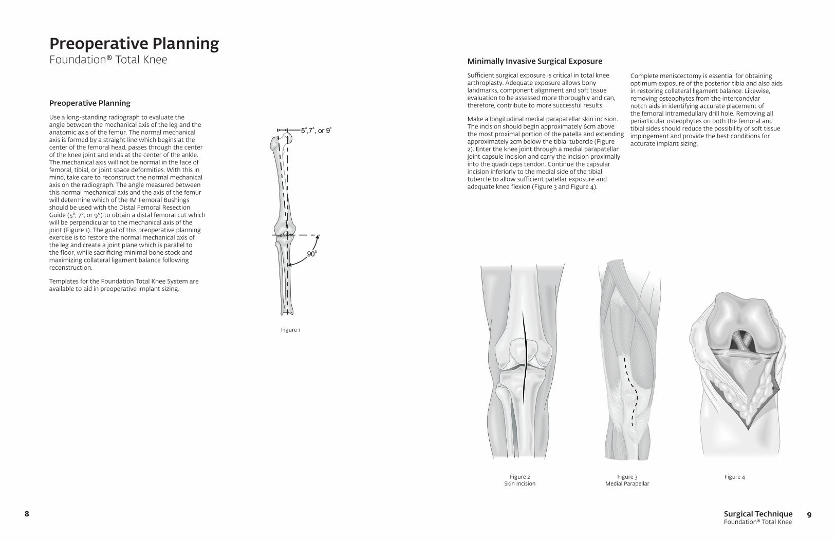
Preoperative Planning
Usealong-standingradiographtoevaluatetheangle between the mechanical axis of the leg and the anatomic axis of the femur. The normal mechanical axis is formed by a straight line which begins at the center of the femoral head, passes through the center of the knee joint and ends at the center of the ankle. The mechanical axis will not be normal in the face of femoral, tibial, or joint space deformities. With this in mind, take care to reconstruct the normal mechanical axis on the radiograph. The angle measured between this normal mechanical axis and the axis of the femur will determine which of the IM Femoral Bushings should be used with the Distal Femoral Resection Guide(5°,7°,or9°)toobtainadistalfemoralcutwhichwill be perpendicular to the mechanical axis of the joint (Figure 1). The goal of this preoperative planning exercise is to restore the normal mechanical axis of the leg and create a joint plane which is parallel to the floor, while sacrificing minimal bone stock and maximizing collateral ligament balance following reconstruction.
Templates for the Foundation Total Knee System are available to aid in preoperative implant sizing.
Figure 1
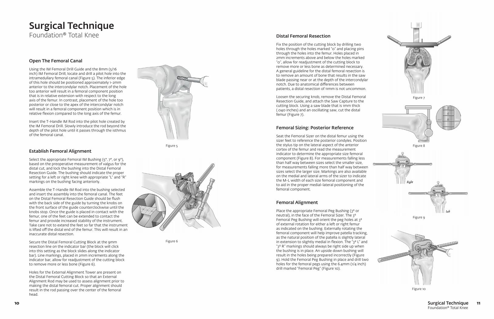
Minimally Invasive Surgical Exposure
Sufficientsurgicalexposureiscriticalintotalkneearthroplasty. Adequate exposure allows bony landmarks, component alignment and soft tissue evaluation to be assessed more thoroughly and can, therefore, contribute to more successful results.
Make a longitudinal medial parapatellar skin incision. The incision should begin approximately 6cm above the most proximal portion of the patella and extending approximately 2cm below the tibial tubercle (Figure 2). Enter the knee joint through a medial parapatellar joint capsule incision and carry the incision proximally into the quadriceps tendon. Continue the capsular incision inferiorly to the medial side of the tibial tubercletoallowsufficientpatellarexposureandadequate knee flexion (Figure 3 and Figure 4).
Figure 2 Skin Incision
Figure 3 Medial Parapellar
Figure 4
Complete meniscectomy is essential for obtaining optimum exposure of the posterior tibia and also aids in restoring collateral ligament balance. Likewise, removing osteophytes from the intercondylar notch aids in identifying accurate placement of the femoral intramedullary drill hole. Removing all periarticular osteophytes on both the femoral and tibial sides should reduce the possibility of soft tissue impingement and provide the best conditions for accurate implant sizing.
Surgical TechniqueFoundation® Total Knee
1110
Surgical TechniqueFoundation® Total Knee
Open The Femoral Canal
UsingtheIMFemoralDrillGuideandthe8mm(5/16inch) IM Femoral Drill, locate and drill a pilot hole into the intramedullary femoral canal (Figure 5). The inferior edge of this hole should be positioned approximately 1-2mm anterior to the intercondylar notch. Placement of the hole too anterior will result in a femoral component position that is in relative extension with respect to the long axis of the femur. In contrast, placement of the hole too posterior or close to the apex of the intercondylar notch will result in a femoral component position which is in relative flexion compared to the long axis of the femur.
InserttheT-HandleIMRodintothepilotholecreatedbythe IM Femoral Drill. Slowly introduce the rod beyond the depth of the pilot hole until it passes through the isthmus of the femoral canal.
Distal Femoral Resection
Fix the position of the cutting block by drilling two holes through the holes marked “0” and placing pins throughtheholesintothefemur.Holesplacedin2mm increments above and below the holes marked “0”, allow for readjustment of the cutting block to remove more or less bone as determined necessary. A general guideline for the distal femoral resection is to remove an amount of bone that results in the saw blade passing near or at the depth of the intercondylar notch. Due to anatomical differences between patients, a distal resection of 11mm is not uncommon.
Loosen the securing knob, remove the Distal Femoral ResectionGuide,andattachtheSawCapturetothecuttingblock.Usingasawbladethatis1mmthick(.040 inches) and an oscillating saw, cut the distal femur (Figure 7).
Femoral Sizing: Posterior Reference
Seat the Femoral Sizer on the distal femur using the sizer feet to reference the posterior condyles. Position the stylus tip on the lateral aspect of the anterior cortex of the femur and read the measurement indicator to determine the appropriate size femoral component (Figure 8). For measurements falling less than half way between sizes select the smaller size, for measurements falling more than half way between sizes select the larger size. Markings are also available on the medial and lateral arms of the sizer to indicate the M-L width of each size femoral component and to aid in the proper medial-lateral positioning of the femoral component.
Femoral Alignment
Place the appropriate Femoral Peg Bushing (3º or neutral), in the face of the Femoral Sizer. The 3º Femoral Peg Bushing will orient the peg holes at 3º of external rotation for either a left or right femur as indicated on the bushing. Externally rotating the femoral component will help improve patella tracking, as the natural position of the patella is slightly lateral in extension to slightly medial in flexion. The “3º L” and “3º R” markings should always be right side up when the bushing is in place. An upside down bushing will result in the holes being prepared incorrectly (Figure 9).HoldtheFemoralPegBushinginplaceanddrilltwoholes for the femoral pegs using the 6.4mm (1/4 inch) drill marked “Femoral Peg” (Figure 10).
Figure 5
Figure 6
Figure 7
Figure 8
Figure 9
Figure 10
Establish Femoral Alignment
Select the appropriate Femoral IM Bushing (5°, 7°, or 9°), based on the preoperative measurement of valgus for the distal cut, and lock the bushing into the Distal Femoral ResectionGuide.Thebushingshouldindicatethepropersetting for a left or right knee with appropriate “L” and “R” markings on the bushing facing anteriorly.
AssembletheT-HandleIMRodintothebushingselectedand insert the assembly into the femoral canal. The feet ontheDistalFemoralResectionGuideshouldbeflushwith the back side of the guide by turning the knobs on the front surface of the guide counterclockwise until the knobs stop. Once the guide is placed in contact with the femur, one of the feet can be extended to contact the femur and provide increased stability of the instrument. Take care not to extend the feet so far that the instrument is lifted off the distal end of the femur. This will result in an inaccurate distal resection.
Secure the Distal Femoral Cutting Block at the 9mm resection line on the indicator bar (the block will click into this setting as the block slides along the indicator bar). Line markings, placed in 2mm increments along the indicator bar, allow for readjustment of the cutting block to remove more or less bone (Figure 6).
HolesfortheExternalAlignmentTowerarepresentonthe Distal Femoral Cutting Block so that an External Alignment Rod may be used to assess alignment prior to making the distal femoral cut. Proper alignment should result in the rod passing over the center of the femoral head.

Surgical TechniqueFoundation® Total Knee
1312
Surgical TechniqueFoundation® Total Knee
Femoral Sizing: Anterior Reference
Seat the Femoral Sizer on the distal femur using the sizer feet to reference the posterior condyles. Allow the anterior portion of the guide to float with the stylus tip until it is positioned on the lateral aspect of the anterior cortex of the femur. Secure the stylus tip in the correct position by tightening the Stylus Locking Knob. Turn the knurled Actuation Knob down until it is flush with the Stylus Locking Knob and read the measurement indicator to determine the appropriate size femoral component (Figure 11). For measurements falling less than half way between sizes, select the smaller size; for measurements falling more than half way between sizes, select the larger size. Markings are also available on the medial and lateral arms of the sizer to indicate the M-L width of each size femoral component.Usethesemarkingstoproperlypositionthe component medial-lateral on the femur.
Place the appropriate femoral peg bushing (3º or neutral) for the size to be used into the face of the anterior sizer. The 3º Femoral Bushings will orient the peg holes at 3º of external rotation for either a left or right femur as indicated on each bushing. The “3º L” and “3º R” markings should always be right side up when the bushing is in place. An upside down bushing willresultintheholesbeingpreparedincorrectly.Holdthe Femoral Peg Bushing in place and drill two holes for the femoral pegs using the 6.4mm (1/4 inch) drill marked “Femoral Peg” (Figure 12).
Femoral Preparation4-in-1 Speed Blocks
Place the appropriate size 4-in-1 Speed Cut Block on thedistalfemur.QuickLockHandlescanbeattachedto the block for stabilization. As an alternative, the block may be pinned in place using the 3” Bone Pins. Make the anterior cut, posterior cut, and anterior and posterior chamfer cuts using an oscillating saw and a 1mm thick saw blade (Figure 13).
If the speed block has been used as described in Figure 13,placetheappropriatesize1-PieceTrochlearGrooveGuideinplaceonthedistalfemur(thesizeoftheguide should match that of the 4-in-1 Speed Cut Block used). Ream the trochlear groove area with the drill marked “Trochlear” (Figure 14). To facilitate reaming, take care to balance the drill through the guide and initiate reaming prior to engaging the bone.
Figure 11
Figure 12
A-P and Chamfer Blocks
Place the appropriate size Femoral A-P Cut Block on the distal femur. Attach the Saw Capture to the anterior surface of the block and make the anterior cut using an oscillating saw and a 1mm saw blade (Figure 15). Reposition the Saw Capture to the posterior surface of the block to make the posterior cut.
Place the appropriate size Femoral Chamfer Cut Block on the distal femur. Attach the Saw Capture to the anterior surface of the block. Make the anterior chamfer cut. Reposition the Saw Capture to the posterior surface of the block to make the posterior chamfer cut (Figure 16).
With the chamfer block still in place, attach the TrochlearDrillGuidetotheanteriorsurfaceofthe chamfer block, and ream the trochlear groove area with the drill marked “Trochlear” (Figure 17). To facilitate reaming, take care to balance the drill through the guide and initiate reaming prior to engaging the bone.
Figure 13 Figure 14 Figure 15
Figure 16 Figure 17
Surgical TechniqueFoundation® Total Knee
1514
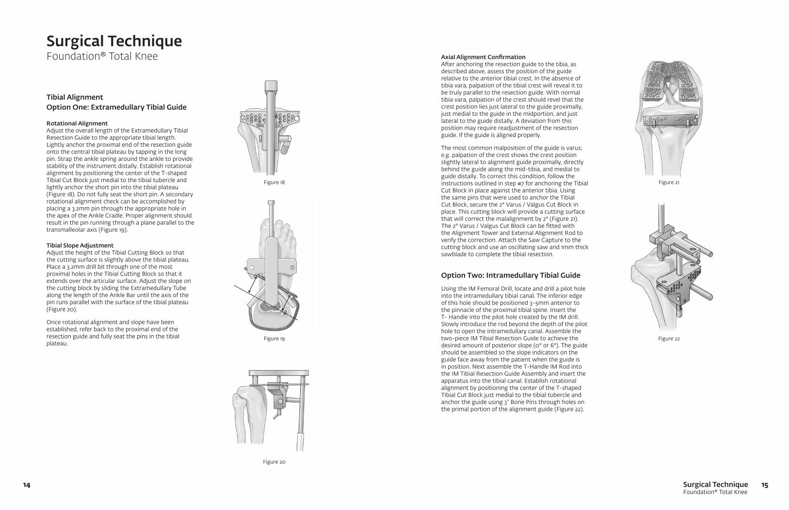
Tibial AlignmentOption One: Extramedullary Tibial Guide
Rotational AlignmentAdjust the overall length of the Extramedullary Tibial ResectionGuidetotheappropriatetibiallength.Lightly anchor the proximal end of the resection guide onto the central tibial plateau by tapping in the long pin. Strap the ankle spring around the ankle to provide stability of the instrument distally. Establish rotational alignment by positioning the center of the T-shaped Tibial Cut Block just medial to the tibial tubercle and lightly anchor the short pin into the tibial plateau (Figure 18). Do not fully seat the short pin. A secondary rotational alignment check can be accomplished by placing a 3.2mm pin through the appropriate hole in the apex of the Ankle Cradle. Proper alignment should result in the pin running through a plane parallel to the transmalleolar axis (Figure 19).
Tibial Slope Adjustment Adjust the height of the Tibial Cutting Block so that the cutting surface is slightly above the tibial plateau. Place a 3.2mm drill bit through one of the most proximal holes in the Tibial Cutting Block so that it extends over the articular surface. Adjust the slope on the cutting block by sliding the Extramedullary Tube along the length of the Ankle Bar until the axis of the pin runs parallel with the surface of the tibial plateau (Figure 20).
Once rotational alignment and slope have been established, refer back to the proximal end of the resection guide and fully seat the pins in the tibial plateau.
Axial Alignment ConfirmationAfter anchoring the resection guide to the tibia, as described above, assess the position of the guide relative to the anterior tibial crest. In the absence of tibia vara, palpation of the tibial crest will reveal it to be truly parallel to the resection guide. With normal tibia vara, palpation of the crest should revel that the crest position lies just lateral to the guide proximally, just medial to the guide in the midportion, and just lateral to the guide distally. A deviation from this position may require readjustment of the resection guide. If the guide is aligned properly.
The most common malposition of the guide is varus; e.g. palpation of the crest shows the crest position slightly lateral to alignment guide proximally, directly behind the guide along the mid-tibia, and medial to guide distally. To correct this condition, follow the instructions outlined in step #7 for anchoring the Tibial CutBlockinplaceagainsttheanteriortibia.Usingthe same pins that were used to anchor the Tibial Cut Block, secure the 2° Varus / Valgus Cut Block in place. This cutting block will provide a cutting surface that will correct the malalignment by 2° (Figure 21). The 2° Varus / Valgus Cut Block can be fitted with the Alignment Tower and External Alignment Rod to verify the correction. Attach the Saw Capture to the cutting block and use an oscillating saw and 1mm thick sawblade to complete the tibial resection.
Option Two: Intramedullary Tibial Guide
UsingtheIMFemoralDrill,locateanddrillapilotholeinto the intramedullary tibial canal. The inferior edge of this hole should be positioned 3-5mm anterior to the pinnacle of the proximal tibial spine. Insert the T-HandleintothepilotholecreatedbytheIMdrill.Slowly introduce the rod beyond the depth of the pilot hole to open the intramedullary canal. Assemble the two-pieceIMTibialResectionGuidetoachievethedesired amount of posterior slope (0° or 6°). The guide should be assembled so the slope indicators on the guide face away from the patient when the guide is inposition.NextassembletheT-HandleIMRodintotheIMTibialResectionGuideAssemblyandinserttheapparatus into the tibial canal. Establish rotational alignment by positioning the center of the T-shaped Tibial Cut Block just medial to the tibial tubercle and anchor the guide using 3” Bone Pins through holes on the primal portion of the alignment guide (Figure 22).
Surgical TechniqueFoundation® Total Knee
Figure 18
Figure 19
Figure 20
Figure 21
Figure 22
Surgical TechniqueFoundation® Total Knee
1716
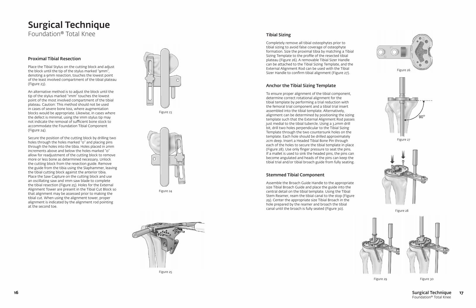
Proximal Tibial Resection
Place the Tibial Stylus on the cutting block and adjust the block until the tip of the stylus marked “9mm”, denoting a 9mm resection, touches the lowest point of the least involved compartment of the tibial plateau (Figure 23).
An alternative method is to adjust the block until the tip of the stylus marked “1mm” touches the lowest point of the most involved compartment of the tibial plateau. Caution: This method should not be used in cases of severe bone loss, where augmentation blocks would be appropriate. Likewise, in cases where the defect is minimal, using the 1mm stylus tip may notindicatetheremovalofsufficientbonestocktoaccommodate the Foundation Tibial Component (Figure 24).
Secure the position of the cutting block by drilling two holes through the holes marked “0” and placing pins throughtheholesintothetibia.Holesplacedin2mmincrements above and below the holes marked “0” allow for readjustment of the cutting block to remove moreorlessboneasdeterminednecessary.Unlockthe cutting block from the resection guide. Remove the guide from the tibia using the Slaphammer, leaving the tibial cutting block against the anterior tibia. Place the Saw Capture on the cutting block and use an oscillating saw and 1mm saw blade to complete thetibialresection(Figure25).HolesfortheExternalAlignment Tower are present in the Tibial Cut Block so that alignment may be assessed prior to making the tibial cut. When using the alignment tower, proper alignment is indicated by the alignment rod pointing at the second toe.
Tibial Sizing
Completely remove all tibial osteophytes prior to tibial sizing to avoid false coverage of osteophyte formation. Size the proximal tibia by matching a Tibial Sizing Template to the profile of the resected tibial plateau(Figure26).AremovableTibialSizerHandlecan be attached to the Tibial Sizing Template, and the External Alignment Rod can be used with the Tibial SizerHandletoconfirmtibialalignment(Figure27).
Anchor the Tibial Sizing Template
To ensure proper alignment of the tibial component, determine correct rotational alignment for the tibial template by performing a trial reduction with the femoral trial component and a tibial trial insert assembled into the tibial template. Alternatively, alignment can be determined by positioning the sizing template such that the External Alignment Rod passes justmedialtothetibialtubercle.Usinga3.2mmdrillbit, drill two holes perpendicular to the Tibial Sizing Template through the two countersunk holes on the template. Each hole should be drilled approximately 2cmdeep.InsertaHeadedTibialBonePinthrougheach of the holes to secure the tibial template in place (Figure28).Useonlyfingerpressuretoseatthepins.If a mallet is used to sink the headed pins, the pins can become angulated and heads of the pins can keep the tibial trial and/or tibial broach guide from fully seating.
Stemmed Tibial Component
AssembletheBroachGuideHandletotheappropriatesizeTibialBroachGuideandplacetheguideintothecentraldetailonthetibialtemplate.UsingtheTibialStem Reamer, ream the tibial canal to the stop (Figure 29). Center the appropriate size Tibial Broach in the hole prepared by the reamer and broach the tibial canal until the broach is fully seated (Figure 30).
Surgical TechniqueFoundation® Total Knee
Figure 23
Figure 24
Figure 25
Figure 27
Figure 30Figure 29
Figure 28
Figure 26

Surgical TechniqueFoundation® Total Knee
1918
All-Polyethylene Component
AssembletheBroachGuideHandletotheTibialDrillGuidemarked“All-Poly”andplacetheguideintothecentraldetailonthetibialtemplate.UsingtheTibialStem Reamer, ream the tibial canal to the stop. Center the tip of the Tibial Broach, marked “All-Poly”, in the pilot hole created by the Tibial Stem Reamer. Broach the proximal tibial canal until the broach is fully seated.
Resurfacing Tibial Component
Usinga3.2mmdrillbit,drillfourholes,approximately1.5cm deep, for the baseplate pegs using the tibial template as a guide (Figure 31).
Resurfaced Patella Preparation
Measure the overall patella thickness using a caliper. PlacethePatellaOsteotomyGuideonthepatellaandset the stylus to indicate an amount of bone equal to the thickness of the patellar component to be used. Usinganoscillatingsawanda1mmthicksawblade,resect the patella. If the initial patellar thickness measures less than 18mm, remove less bone to assure sufficientbonestockforanchoringthepatellarcomponent (Figure 32).
Traditional Patellar Sizing
SizethepatellausingthePatellarSizer/DrillGuide.The center of the appropriate size patella should be positioned medial so that the highest point of the patellar dome replaces the highest point of the normal patella (Figure 33).
Patellar Peg Preparation
Position the Patellar Sizer on the resected patella placing the peg holes in the desired orientation. Press thesharppinonthePatellar/SizerDrillGuideintotheresected patella and drill for the patella pegs using the Patella Peg Stop Drill (Figure 34).
Recessed Patellar Preparation
Measure the overall patellar thickness using a caliper. PlacethePatellaOsteotomyGuideonthepatellaandset the stylus to indicate an amount of bone equal to 2mm less than the thickness of the patellar component to be used (i.e.; if a 10mm Patella is to be used, resect 8mmofbone).Usinganoscillatingsawanda1mmthick saw blade, resect the patella. If the initial patellar thickness measures less than 18mm, remove less bone toassuresufficientbonestockforanchoringthepatellar component. In any case, the thickness of the patella after the osteotomy should not be less than 10mm.
Surgical TechniqueFoundation® Total Knee
Figure 31
Figure 32
Figure 33
Figure 34
Surgical TechniqueFoundation® Total Knee
2120
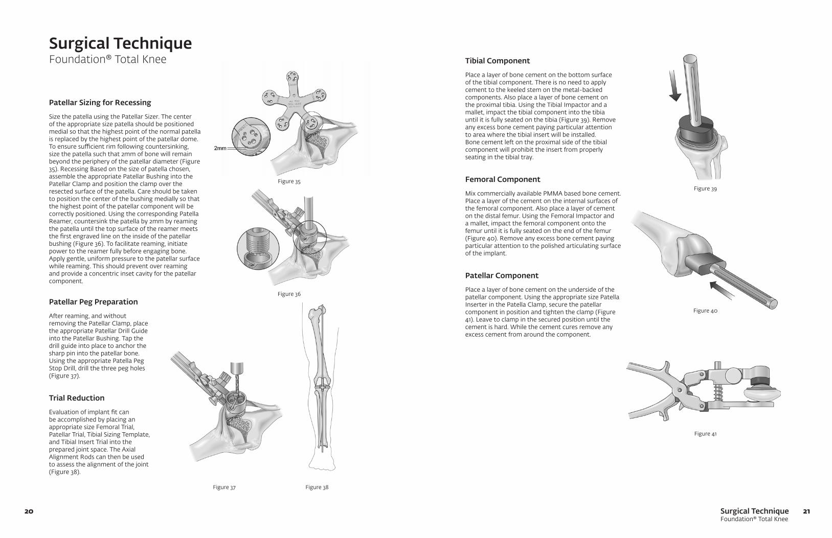
Patellar Sizing for Recessing
Size the patella using the Patellar Sizer. The center of the appropriate size patella should be positioned medial so that the highest point of the normal patella is replaced by the highest point of the patellar dome. Toensuresufficientrimfollowingcountersinking,size the patella such that 2mm of bone will remain beyond the periphery of the patellar diameter (Figure 35). Recessing Based on the size of patella chosen, assemble the appropriate Patellar Bushing into the Patellar Clamp and position the clamp over the resected surface of the patella. Care should be taken to position the center of the bushing medially so that the highest point of the patellar component will be correctlypositioned.UsingthecorrespondingPatellaReamer, countersink the patella by 2mm by reaming the patella until the top surface of the reamer meets the first engraved line on the inside of the patellar bushing (Figure 36). To facilitate reaming, initiate power to the reamer fully before engaging bone. Apply gentle, uniform pressure to the patellar surface while reaming. This should prevent over reaming and provide a concentric inset cavity for the patellar component.
Tibial Component
Place a layer of bone cement on the bottom surface of the tibial component. There is no need to apply cement to the keeled stem on the metal-backed components. Also place a layer of bone cement on theproximaltibia.UsingtheTibialImpactorandamallet, impact the tibial component into the tibia until it is fully seated on the tibia (Figure 39). Remove any excess bone cement paying particular attention to area where the tibial insert will be installed. Bone cement left on the proximal side of the tibial component will prohibit the insert from properly seating in the tibial tray.
Femoral Component
Mix commercially available PMMA based bone cement. Place a layer of the cement on the internal surfaces of the femoral component. Also place a layer of cement onthedistalfemur.UsingtheFemoralImpactoranda mallet, impact the femoral component onto the femur until it is fully seated on the end of the femur (Figure 40). Remove any excess bone cement paying particular attention to the polished articulating surface of the implant.
Patellar Component
Place a layer of bone cement on the underside of the patellarcomponent.UsingtheappropriatesizePatellaInserter in the Patella Clamp, secure the patellar component in position and tighten the clamp (Figure 41). Leave to clamp in the secured position until the cement is hard. While the cement cures remove any excess cement from around the component.
Surgical TechniqueFoundation® Total Knee
Figure 35
Figure 36
Figure 37 Figure 38
Figure 40
Figure 41
Patellar Peg Preparation
After reaming, and without removing the Patellar Clamp, place theappropriatePatellarDrillGuideinto the Patellar Bushing. Tap the drill guide into place to anchor the sharp pin into the patellar bone. UsingtheappropriatePatellaPegStop Drill, drill the three peg holes (Figure 37).
Trial Reduction
Evaluation of implant fit can be accomplished by placing an appropriate size Femoral Trial, Patellar Trial, Tibial Sizing Template, and Tibial Insert Trial into the prepared joint space. The Axial Alignment Rods can then be used to assess the alignment of the joint (Figure 38).
Figure 39
Surgical TechniqueFoundation® Total Knee
2322
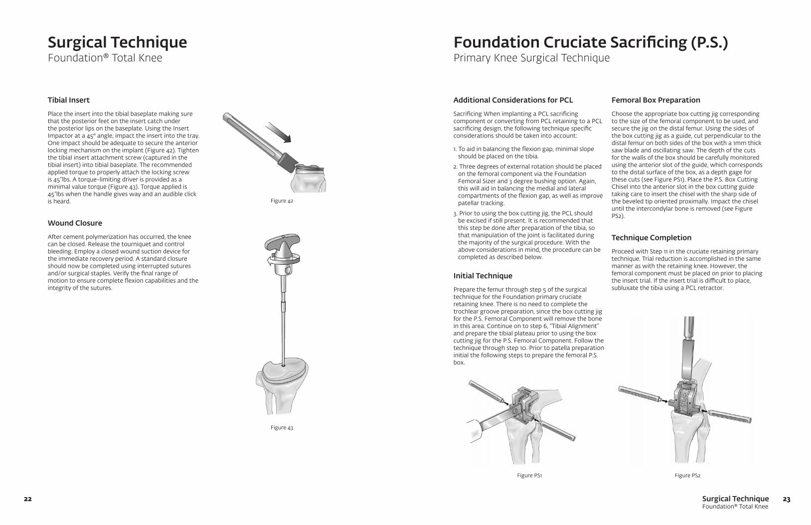
Tibial Insert
Place the insert into the tibial baseplate making sure that the posterior feet on the insert catch under theposteriorlipsonthebaseplate.UsingtheInsertImpactor at a 45° angle, impact the insert into the tray. One impact should be adequate to secure the anterior locking mechanism on the implant (Figure 42). Tighten the tibial insert attachment screw (captured in the tibial insert) into tibial baseplate. The recommended applied torque to properly attach the locking screw is 45”lbs. A torque-limiting driver is provided as a minimal value torque (Figure 43). Torque applied is 45”lbs when the handle gives way and an audible click is heard.
Wound Closure
After cement polymerization has occurred, the knee can be closed. Release the tourniquet and control bleeding. Employ a closed wound suction device for the immediate recovery period. A standard closure should now be completed using interrupted sutures and/or surgical staples. Verify the final range of motion to ensure complete flexion capabilities and the integrity of the sutures.
Additional Considerations for PCL
Sacrificing When implanting a PCL sacrificing component or converting from PCL retaining to a PCL sacrificing design, the following technique specific considerations should be taken into account:
1. To aid in balancing the flexion gap, minimal slope should be placed on the tibia.
2. Three degrees of external rotation should be placed on the femoral component via the Foundation Femoral Sizer and 3 degree bushing option. Again, this will aid in balancing the medial and lateral compartments of the flexion gap, as well as improve patellar tracking.
3. Prior to using the box cutting jig, the PCL should be excised if still present. It is recommended that this step be done after preparation of the tibia, so that manipulation of the joint is facilitated during the majority of the surgical procedure. With the above considerations in mind, the procedure can be completed as described below.
Initial Technique
Prepare the femur through step 5 of the surgical technique for the Foundation primary cruciate retaining knee. There is no need to complete the trochlear groove preparation, since the box cutting jig for the P.S. Femoral Component will remove the bone in this area. Continue on to step 6, “Tibial Alignment” and prepare the tibial plateau prior to using the box cutting jig for the P.S. Femoral Component. Follow the technique through step 10. Prior to patella preparation initial the following steps to prepare the femoral P.S. box.
Surgical TechniqueFoundation® Total Knee
Foundation Cruciate Sacrificing (P.S.)Primary Knee Surgical Technique
Femoral Box Preparation
Choose the appropriate box cutting jig corresponding to the size of the femoral component to be used, and securethejigonthedistalfemur.Usingthesidesofthe box cutting jig as a guide, cut perpendicular to the distal femur on both sides of the box with a 1mm thick saw blade and oscillating saw. The depth of the cuts for the walls of the box should be carefully monitored using the anterior slot of the guide, which corresponds to the distal surface of the box, as a depth gage for these cuts (see Figure PS1). Place the P.S. Box Cutting Chisel into the anterior slot in the box cutting guide taking care to insert the chisel with the sharp side of the beveled tip oriented proximally. Impact the chisel until the intercondylar bone is removed (see Figure PS2).
Technique Completion
Proceed with Step 11 in the cruciate retaining primary technique. Trial reduction is accomplished in the same manneraswiththeretainingknee.However,thefemoral component must be placed on prior to placing theinserttrial.Iftheinserttrialisdifficulttoplace,subluxate the tibia using a PCL retractor.
Figure 42
Figure 43
Figure PS2Figure PS1

0010307-001 rev. C 06/12©2011 Encore Medical, L.P.
CAUTION: Federal Law (USA)
restricts this device to sale by
or on the order of a physician.
See package insert
for a complete listing of
indications, contraindications,
warnings, and precautions.
TM
DJO Surgical I A DJO Global CompanyT 800.456.8696 D 512.832.9500 F 512.834.6300
9800 Metric Blvd. I Austin, TX 78758 I U.S.A.djosurgical.com