Foundation Design
22
Choice of the Type of Foundation The choice of the appropriate type of foundation is governed by some important factors such as 1. The nature of the structure 2. The loads exerted by the structure 3. The subsoil characteristics 4. The allotted cost of foundations Therefore to decide about the type of foundation, subsoil exploration must be carried out. Then the soil characteristics within the affected zone below the building should be carefully evaluated. The allowable bearing capacity of the affected soil strata should then be estimated. After this study, one could then decide whether shallow foundations or deep foundations should be used. Shallow foundations, such as footings and rafts, cost less and easier to execute. They could be used if the following two conditions are fulfilled; 1. The superimposed stress (∆p) caused by the building lies within the allowable bearing capacity diagram of different soil strata as shown in Fig.1. This condition is fulfilled when , in Fig.1, is smaller than and smaller than and smaller than and smaller than and so on. 2. The building could withstand the expected settlement estimated for that type of foundation If one or both of these two conditions cannot be fulfilled the use of deep foundations should be considered. Deep foundations are used when top layers of the soil are soft and there exists a good bearing stratum at a reasonable depth. Soil strata lying beneath the bearing stratum should be of ample strength to resist the superimposed stresses (∆p) due to the loads transmitted to the bearing stratum, as shown in Fig.2. Page 1 of 73 FOUNDATION 6/15/2009 http://osp.mans.edu.eg/sfoundation/foundtion.htm
-
Upload
alexious-demide -
Category
Documents
-
view
42 -
download
4
description
A brief explanation of foundation solutions
Transcript of Foundation Design

Choice of the Type of Foundation
The choice of the appropriate type of foundation is governed by some important factors such as
1. The nature of the structure
2. The loads exerted by the structure
3. The subsoil characteristics
4. The allotted cost of foundations
Therefore to decide about the type of foundation, subsoil exploration must be carried out. Then the soil characteristicswithin the affected zone below the building should be carefully evaluated. The allowable bearing capacity of the affectedsoil strata should then be estimated.
After this study, one could then decide whether shallow foundations or deep foundations should be used.
Shallow foundations, such as footings and rafts, cost less and easier to execute. They could be used if the following twoconditions are fulfilled;
1. The superimposed stress (∆p) caused by the building lies within the allowable bearing capacity diagram of different soil strata as shown in Fig.1.
This condition is fulfilled when , in Fig.1, is smaller than and smaller than and smaller than and smaller thanand so on.
2. The building could withstand the expected settlement estimated for that type of foundation
If one or both of these two conditions cannot be fulfilled the use of deep foundations should be considered.
Deep foundations are used when top layers of the soil are soft and there exists a good bearing stratum at a reasonabledepth. Soil strata lying beneath the bearing stratum should be of ample strength to resist the superimposed stresses (∆p) due to the loads transmitted to the bearing stratum, as shown in Fig.2.
Page 1 of 73FOUNDATION
6/15/2009http://osp.mans.edu.eg/sfoundation/foundtion.htm

Deep foundations are usually piles or piers which transmits the load of the building to the good bearing stratum. Theyusually cost more and require well trained engineers to execute.
If the explored soil layers are soft for considerable depth and no bearing stratum is found at a reasonable depth, floatingfoundations could be used.
To build a floating foundation, a mass of soil, approximately equal to the weight of the proposed building, is to be removed and replaced by the building. In this case, the bearing stress under the building will be equal to the weight of the removed earth (γD) which is less than
(qa = γD +2C)
and ∆p will be equal to zero. This means that the bearing capacity under the building is less than ( qa ) and the expected settlement equals theoretically to zero.
Finally, the engineer should prepare an estimate of the cost of the most promising type of foundation which representsthe most acceptable compromise between performance and cost.
Shallow Foundations
Shallow foundations are those executed near the ground surface or at shallow depths. As mentioned before in theprevious chapter, shallow foundations are used when subsoil exploration proves that all soil strata affected by thebuilding could resist the superimposed stresses (∆p) without causing excessive settlements.
Shallow foundations are either footings or rafts.
Footings
Footing foundation is one of the oldest and most popular type of shallow foundations. A footing is an enlargement of thebase of a column or wall for the purpose of distributing the load on the supporting soil at a pressure suiting its properties.
Types of Footings
Page 2 of 73FOUNDATION
6/15/2009http://osp.mans.edu.eg/sfoundation/foundtion.htm

There are different types of footings to suit the nature of the structure. Footings could be classified into three mainclasses
Wall or Strip footing
It runs underneath the wall by its full length as shown in Fig.3. it is usually used in the bearing wall type structures.
Isolated column footing
It acts as a base for a column. It is usually used for reinforced concrete Skelton type of buildings. It can take any shapesuch as square, rectangular or circular as shown in Fig.4.
Fig.4 Typical spread footings
Combined Column Footing
It is a combined base for an exterior and interior columns of a building, Fig.5. It is also used when two adjacent columns of a building are close to each other that their footings overlap
Page 3 of 73FOUNDATION
6/15/2009http://osp.mans.edu.eg/sfoundation/foundtion.htm

Distribution of stresses under footings
The distribution of stresses under footings is considered linear although it is not the case in reality, The error involved inthis assumption is small and could be overlooked.
Load Compilations
Loads affecting the usual types of buildings are:
1. Dead Load (D.L) 2. Live Load (L.L) 3. Wind Load (W.L) 4. Earthquake Load (E.L)
Dead Load
The full dead load acting on the elements of the structures should be considered in the design.
Live Load
It is not probable that the full intensity of the live load will be acting at the same time on all the floors of a multi-storey building. Consequently, the codes of practice allow a certain reduction in the intensity of live load. According to theEgyptian Code of practice the following reduction in live load is allowed:
No. of floors Reduction in live load %
Ground floor zero %
1st floor zero %
2nd floor 10.0 %
3rd floor 20 0 %
Page 4 of 73FOUNDATION
6/15/2009http://osp.mans.edu.eg/sfoundation/foundtion.htm

3rd floor 20.0 %
4th floor 30.0 %
5th floor and above 40.0 %
The live load should not be reduced for ware houses and public buildings such as schools, cinemas, and hospitals.
Wind and Earthquake Loads
When the buildings are high and narrow the wind pressure and the earthquake load must be taken into consideration.
Assumption used in the Design of Spread Footings
Theory of elasticity analysis indicates that the stress distribution beneath footings, symmetrically loaded, is not uniform. The actual stress distribution depends on the type of material beneath the footing and the rigidity of the footing. Forfootings on loose cohesion-less material, the soil grains tend to displace laterally at the edges from under the load, whereas in the center the soil is relatively confined. This results in a pressure diagram somewhat as indicated in Fig.6.For the general case of rigid footings on cohesive and cohesion-less materials, Fig.6 indicates the probable theoretical pressure distribution. The high edge pressure may be explained by considering that edge shear must take place beforesettlement can take place.
Because the pressure intensities beneath the footing depend on the rigidity of the footing, the soil type and the condition of the soil, the problem is generally indeterminate. It is common practice to use a linear pressure distribution beneath the footings and this procedure will be followed in this text. In any case little difference in design results by using a linear pressure distribution
Allowable Bearing Stresses under Footings
The factor of safety in the calculating of the allowable bearing capacity under the footing should not be less than 3 if theloads considered in the design is equal to the dead load + the reduced live load. The factor of safety should not be lessthan 2 when the severest condition of loading is considered, which is, dead load + full live load + wind load orearthquake loads.
The loads of the superstructure are usually calculated at ground level. If the net allowable bearing pressure is given, itshould be reduced by the volume of concrete below ground surface per unit area of the footing multiplied by thedifference between the unit weight of concrete and soil. If we assume equal to the average density of soil and concrete
Page 5 of 73FOUNDATION
6/15/2009http://osp.mans.edu.eg/sfoundation/foundtion.htm

difference between the unit weight of concrete and soil. If we assume equal to the average density of soil and concreteFig.7, then should be reduced by
Structural design of spread footings
For spread footing the following items should be considered
1-Shear
Shear stresses ate usually control the depth of spread footings. The critical section for wide beam shear is shown inFig.8-a. It is at a distance d from the column or wall face. The values of the shear stresses are given in table 1.Thecritical section for punching shear (Two-way diagonal shear) is shown in Fig.8-b. It is at distance of d/2 from the face of the column. This assumption is according to the American Concrete Institute (A.CI) Code.
Page 6 of 73FOUNDATION
6/15/2009http://osp.mans.edu.eg/sfoundation/foundtion.htm

Table(1): allowable stresses in concrete and reinforcement:-
Punching shear will generally control the depth of the spread footings. From principles of statics Fig.8-b , the force on the critical section for shear is equal to the force on the footing beyond the shear section caused by the net soil pressure fn.
where qp = allowable punching shear stress
= 8 kg/cm2 (for cube strength =160)
fn = net soil pressure
b = Side of column
d =depth of punching shear
It can be assumed that the critical section for punching shear is at the column face and in this case the allowablepunching shear stress can be taken as 10.0 kg/cm2 (for cube strength = 160).
The footing is usually designed to ensure that the depth is great enough to resist the shear by concrete with out webreinforcement..
2- Bond
Bond stress is computed as
where the shear force Q is taken at the same critical section for bending moment, or where changes in concrete crosssection or steel reinforcement occur. For footings of constant section, the section for bond is at the face of column orwall The reinforcing bar should have enough length d Fig 9 to avoid the pull out (bond failure) or a splitting of the
Types of stresses symbol Allowable stresses in kg/cm2
Cube strength fcu 180 200 250 300 Axial comp. fco 45 50 60 70 Simple bending and eccentric forces with big eccentricity fc 70 80 95 105
Shear stresses
Slabs and footings without reinf.
Other members
Members with reinforcement
q1
q1
q2
7
5
15
8
6
17
9
7
19
9
7
21 Punching shear qcp 7 8 9 10 Reinforcement
Mild steel 240/350
Steel 280/450
Steel 360/520
Steel 400/600
fs
1400
1600
2000
2200
1400
1600
2000
2200
1400
1600
2000
2200
1400
1600
2000
2200
Page 7 of 73FOUNDATION
6/15/2009http://osp.mans.edu.eg/sfoundation/foundtion.htm

wall. The reinforcing bar should have enough length dd , Fig.9 to avoid the pull-out (bond failure) or a splitting of the concrete. The value of dd is computed as follows:
For the first computation take equal to allowable working stress. If the calculated d is larger than the available dthen recalculate d by taking equal to the actual steel stress.
The allowable values of bond stress qb are as follows
3- Bending moment
The critical sections for bending moment are determined from Fig.10 as follows:
Page 8 of 73FOUNDATION
6/15/2009http://osp.mans.edu.eg/sfoundation/foundtion.htm

For concrete wall and column, this section is taken at the face of the wall or the column Fig.10-a.
For masonry wall this section is taken halfway between middle and the edge of the wall Fig.10-b.
For steel column, this section is located half way between the edge of base plate and the face of the column Fig.(10-c).
The depth required to resist bending moment is
4- Bearing on top of footing
When a reinforced concrete column transmits its load to the footing, the steel of the column, which is carrying a portion ofthe load, cannot be terminated on top of footing since this may overstress the concrete in column contact area. Thereforeit is necessary to transmit the portion of load carried by the column steel by bond stress into the footing by eitherextending the column steel or by dowels. From Fig.11:
where is the actual steel stress
Page 9 of 73FOUNDATION
6/15/2009http://osp.mans.edu.eg/sfoundation/foundtion.htm

5- Plain Concrete Footing Beneath R.C. Footing
It is common practice to place a plain concrete layer beneath the reinforced concrete footing. This layer is about 20 cm.to 40 cm. The projection C of the plain concrete layer depends on its thickness t. Referring to Fig.12 , the maximumbending moment per unit length at section a-a is given by
Where fn = the net soil pressure.
The maximum tensile stress at the bottom of section a-a is:
Page 10 of 73FOUNDATION
6/15/2009http://osp.mans.edu.eg/sfoundation/foundtion.htm

DESIGN OF R.C. WALL FOOTING:
The wall footing is a strip of reinforced concrete wider than the wall. Fig.13 shows the different types of wall footings. Thetype shown in Fig.13-a is used for footings carry light loads and placed on uniform soil of good bearing capacity. Thetype shown in Fig.13-b is used when the soil under the footing is not uniform and of different bearing capacities. The typeshown in Figs.13-c and 13-d is used for heavy loadings.
Design Procedure:
Consider 1.0 meter length of the wall.
1. Find P at ground level.
2. Find if is given then it is reduced by or compute PT .
3. Compute the area of footing
Page 11 of 73FOUNDATION
6/15/2009http://osp.mans.edu.eg/sfoundation/foundtion.htm

If the bond stress is not safe, we either increase by using steel bars with smaller diameter, or increase ∑ Othe depth d. Bending up the steel reinforcement at the edges of the footing helps in resisting bond stresses. Thediameter of the main steel reinforcement should not be less than 12 mm. To prevent cracking due to unevensettlement below the wall itself, additional reinforcement is used as shown in Fig.13-c and d. It is taken as 1.0% of the concrete cross section under the wall and distributed equally at top and bottom.
19. Check the anchorage bond
Page 12 of 73FOUNDATION
6/15/2009http://osp.mans.edu.eg/sfoundation/foundtion.htm

Design of Single Column Footing
The single column footings are usually square in plan, Rectangular footings are used if there restriction in one direction or If the supported columns are of too elongated .rectangular cross section. In the simplest form, they consist of a single slab FIg.15-a. Fig.15-b shows a pedestaled column footing, the pedestal provides depth for a more favorable transfer of load and in many cases is
required in order to provide the necessary length for dowels. Sloped footings such as those in Fig.15-c
Design Procedure for Square Column Footing
American Codes of Practice is equal to the moment about the critical section y-y of the net stress acting on the hatched .areaabcd Fig. 16-a. According to the Continental Codes of practiceMmax. is equal to either; the moment of the net stresses actingon the hatched area abgh, shown in Fig.16-b, about the critical section y-y or 0.85 the moment of the net stresses acting on the area abcd in Fig.16-a about y-y.
Page 13 of 73FOUNDATION
6/15/2009http://osp.mans.edu.eg/sfoundation/foundtion.htm
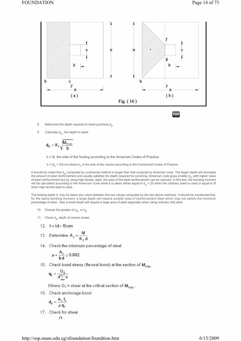
8. Determine the depth required to resist punching dp.
9. Calculate dm, the depth to resist
b = B, the side of the footing according to the American Codes of Practice
b = (bc + 20) cm where bc is the side of the column according to the Continental Codes of Practice.
It should be noted that dm computed by continental method is larger than that compute by American code. The larger depth will decreasethe amount of steel reinforcement and usually satisfies the depth required for punching. American code gives smaller dm with higher value of steel reinforcement but by using high tensile, steel, the area of the steel reinforcement can be reduced. In this text, the bending momentwill be calculated according to the American Code while b is taken either equal to bc + 20 when the ordinary steel is used or equal to B when high tensile steel is used.
The footing depth d may be taken any value between the two values computed by the two above methods. It should be mentioned that,for the same bending moment, a large depth will require smaller area of reinforcement steel which may not satisfy the minimumpercentage of steel . Also a small depth will require a large area of steel especially when using ordinary mild steel.
10. Choose the greater of dm or dp
11. Check dd, depth of column dowel.
Page 14 of 73FOUNDATION
6/15/2009http://osp.mans.edu.eg/sfoundation/foundtion.htm

Design Procedure for Rectangular Footing
The procedure is the same as square footing. The depth is usually controlled by punching shear except If the ratio of length to width islarge, the wide beam shear may control the depth. The critical sections for shear are at distance d from both sides of the column Fig.17-a. The bending moment is calculated for both directions, about 1-1 axis and about b-b axis as shown in Fig.17.b and c.
The reinforcement in the long direction (Side L) is calculated from the bending moment , and is uniformly distributed over the width B. Thereinforcement in the short direction (Side B) is calculated from the bending moment . In locating the bars in the short direction one has to consider that the support provided to the footing by the column is concentrated near the middle, consequently the area of footingadjacent to the column is more effective in resisting bending. For this reason an adjustment of steel in the short direction is made. Thisadjustment place a percentage of the steel in a zone centered on the column with a width equal to the length of the short direction of thefooting. The remainder of the reinforcement shall be uniformly distributed in two end zones, Fig.18. According to the American ConcreteInstitute, the percentage of steel in the central zone is given by:
where S = ratio of long side to short side, L/B .
Page 15 of 73FOUNDATION
6/15/2009http://osp.mans.edu.eg/sfoundation/foundtion.htm

SEMELLES
Single footings should be tied together by beams known as semelles as shown in Fig.19.a. Their function is to carry the ground floor wallsand transfer their loads to the footings. Semelles can prevent relative settlement if they are of very stiff section and heavily reinforced.
The semelle is designed as continuous reinforced concrete rectangular beam carrying the weight of the wall. The width of the semelle is equal to the width of the wall plus 5 cm and it should not be less than 25 cm. It should resist the shearing forces and bending moments to which it is subjected, semelles must
be reinforced at top and bottom to counteract the differential settlements. by the equal reinforcement As.
The top level of the semelle should be 20 cm below the level of the platform surrounding the building. If the level of the ground floor is higher than that of the platform, the level of the inner semmelle can be taken 20 cm below the ground floor level
Footings subjected to Moment
Introduction
Many foundations resist, in addition to the concentric vertical load, a moment about one or both axis of the footing. The momentmay result from a load applied off the centre of the footing . Examples of foundations that must resist moment are those for retaining walls,abutments , bridge piers, and the columns of the foundations of tall buildings where wind pressure causes appreciable bending momentsat the base of columns.
Page 16 of 73FOUNDATION
6/15/2009http://osp.mans.edu.eg/sfoundation/foundtion.htm

The soil-pressure resultant under eccentrically loaded footing is assumed to coincide with the axial load P, but not with thecentroid of the footing, which results in a linear non-uniform pressure distribution. The maximum pressure must not exceed the maximum allowable pressure on the soil. Tilting of the footing due to the higher intensity of soil pressure at the toe is possible to occur . This can bereduced by using a large safety factor when computing the allowable soil pressure. Chapter 1, Section "Footings with Eccentric or InclinedLoads" provide for a reduction in allowable soil pressure for eccentrically loaded footings.
Footings with Moments or Eccentricity about One Axis
where P = vertical load or resultant force
Page 17 of 73FOUNDATION
6/15/2009http://osp.mans.edu.eg/sfoundation/foundtion.htm

e = eccentricity of vertical load or resultant force
q = intensity of soil pressure (+ = compression)
and should not be greater than the allowable
soil pressure qa
c-The Load P is Outside Middle
When the load P is outside the middle third, that is e > L/6, Eq.7 indicates that tension will occur under the footing. However, no tension can develop between the soil and the footing, thus the tension stresses are neglected, and the areaof the footing which is in tension is not considered effective in carrying load. Therefore the pressure diagram on the soilshould be always in compression as shown in Fig.21-.c. For the eccentricity e > L/6 with respect to one axis only, one can drive equations for the maximum soil pressure q1 by finding a compressive pressure diagram whose resultant should be equal and on the same line of action of load P. This diagram will take the shape of triangle whose side = q1and base =
Footings with Moments or Eccentricity about both Axis
For footings with moments or eccentricity about both axis Fig 22, the pressure may be computed by the followingequation
Page 18 of 73FOUNDATION
6/15/2009http://osp.mans.edu.eg/sfoundation/foundtion.htm

a- The Neutral Axis Outside the Base :
If the neutral axis is outside the base, then all the pressure q is in compression and equation (9) is valid. Thelocation of the maximum and minimum pressures on soil may be determined readly by observing the directions of themoments. The maximum pressure q1 is at point (1)
Fig.22-a and the minimum pressure q2 is at point (3). The pressure q1 and q2 are determined from Eq.(9).
b- The Neutral Axis Cuts the Base
If the neutral axis cuts the base, then a certain area of the base is subjected to tension Fig.22. As the soil is not likelyto grip the footing to hold it in place , therefore the diagram shown in Fig.22-b and Eq.(9) cannot be used. The computation of the maximum pressure on soil must be based on the area actually in compression. The compressivediagram is to be found in such a way that its resultant should be equal and on the same line of action of the force P. Thesimplest way to get this diagram is by trial and error as follows:
1- Find soil pressure at all corners by applying Eq.(9).
2- Determine the position of the neutral axis N-A (the line of zero pressure). This is not a straight line, but for theproblem it is assumed to be . Therefore it is only necessary to find two points, one on each adjacent side of thefooting.
3- Select another neutral axis (N'-A') parallel to (N-A) but somewhat closer to the location of the resultant load Pacting on the footing.
4- Compute the moment of inertia of the area in compression with respect to the N'-A' . The simplest procedure is to draw the footing to scale and divide the area into rectangles and triangles
Page 19 of 73FOUNDATION
6/15/2009http://osp.mans.edu.eg/sfoundation/foundtion.htm

draw the footing to scale and divide the area into rectangles and triangles
4.4 STRUCTURAL DESIGN OF FOOTINGS SUBJECTED TO MOMENT
The principle problem in the design of eccentrically loaded footings is the determination of the pressures distributionunder the footings. Once they have been determined, the design procedure will be similar to the concentrically loadedfootings, the critical sections are selected and computations of the stresses due to moment and shear are made.
Where the bending moments on a column come from any direction, for example from wind loads, a square footing-; is preferable unless the space restrictions dictate the choice of rectangular footing. If the bending moments always act in the same direction, as in columns supporting rigid framed structures, the footing can be lengthed in the direction of the eccentricity
The dimensions of the footing B and L are proportioned in such a way that the maximum pressure at the toe does notexceed the allowable soil pressure .
If a column carries a permanent bending moment, for example a bracket carrying a sustained load, it may be advantage to place the column off centre on the footing so that the eccentricity of the resultant loading is zero In this case the distribution of the pressure on the base will be uniform. The long toe section of the footing should be designed as a cantilever about a section through the face of the column, Calculation of the depth to resist punching shear and wide beam shear is the same as in footings support concentric loads
Since the bending moment at the base of the column is likely to be large for this type of footing, the column reinforcement should be properly tied into the footing., Reinforcement details for this type of footings are shown in Fig.24.
For square footing it is generally most convenient to keep bar diameter and spacing the same in both directions in orderto avoid confusion in steel fixing.
Page 20 of 73FOUNDATION
6/15/2009http://osp.mans.edu.eg/sfoundation/foundtion.htm

Combined Footings
Introduction
The preceding section presented elements of the design of spread and wall footings. This section considers some of themore complicated shallow-foundation problems. Among these are footings supporting more than one column in a line(combined footings), which may be rectangular or trapezoidal in shape, or two pads connected by a beam, as for a strapfooting. Eccentrically loaded footings and un-symmetrically shaped footings will also be considered.
Rectangular Combined Footings
When property lines, equipment locations, column spacing, or other considerations limit the footing clearance at thecolumn locations, a possible solution is the use of a rectangular-shaped footing. This type of footing may support two columns, as illustrated in Fig.25 and 26, or more than two columns with only slight modification of the design procedure.These footings are commonly designed by assuming a linear stress distribution on the bottom of the footing, and if theresultant of the soil pressure coincides with the resultant of the loads (and center of gravity of the footing), the soilpressure is assumed to be uniformly distributed, The linear pressure distribution implies a rigid footing on ahomogeneous soil. The actual footing is generally not rigid, nor is the pressure uniform beneath it, but it has been foundthat solutions using this concept are adequate. This concept also results in a rather conservative design.
Page 21 of 73FOUNDATION
6/15/2009http://osp.mans.edu.eg/sfoundation/foundtion.htm

The design of a rigid rectangular footing consists in determining the location of the center of gravity (cg) of the column loads and using length and width dimensions such that the centroid of the footing and the center of gravity of the column loads coincide. With the dimensions of the footing established, a shear
and moment diagram can be prepared, the depth selected for shear (again it is conventional to make the depth adequatefor shear without using shear reinforcement to satisfy rigidity requirements implicitly), and reinforcing steel selected forbending requirements. Critical sections for shear, both diagonal-tension and wide-beam, should be taken as indicated in the previous section. The maximum positive and negative moments are used to design the reinforcing steel and willresult in steel in both bottom and top of the beam.
In the short direction, obviously, the entire length is not going to be effective in resisting bending. That zone closest to the column will be most effective for bending, and it is recommended that this approach be used. This is basically what the ACI Code specifies in Art. 15.4.4 for rectangular footings
Page 22 of 73FOUNDATION
6/15/2009http://osp.mans.edu.eg/sfoundation/foundtion.htm