Foundation Calculation
63
Drawing
-
Upload
comanadrian -
Category
Documents
-
view
52 -
download
3
Transcript of Foundation Calculation

Drawing

Foundation Calculation
Description: 14550E001SN 00152Bowthruster room
Project: JSS
Author: ALI
Date: 3/23/2011
File: 'file:///tt/file_convert/55cf9a04550346d033a02246/document.xls'#$Foundation Calculation
Vulnerability Y/N N
Shock zone / category 0
UWN category -
Seating code -
Noise control spec Y/N Y
1. Vertical loading (on "z" direction) General Input:
W1 4000 [Kg] distributed weight
W2 4000 [Kg] point load weight
a) Bending stress f 3 (minim) acceleration factor
Span maxim S 2.78 [m] f1 0.6 safety factor
Total length of found. L=2x0.9+2 x 5 11.8 [m] s 355 [N/mm2]
Mass per length M = W1 / L 339 [Kg/m] a 9.8 [m/s2] acceleration
Point load on S F=SxW2xfxa/L 27706 [N] s 213 [N/mm2] allowable bending stress
Distributed load Q = M x f x a 9967 [N/m] t 213 [N/mm2] allowable shear stress
Load type
Distributed <=== Choose
Distributed 9629 [Nm]
Point Mmp = F x S/4 19256 [Nm]
Distributed+Point Mmd + Mmp 28885 [Nm]
Bending moment max 9629 [Nm]
Section modulus min 46 [cm3]
Profile chosed =====> HEB160 116 [cm3] OK
b) Compresive stress
Leg's no. of foundation 10
2. Longitudinal loading (on "x" direction)
Mmd = Q x S2/8
SMmin = Mm/s

Foundation Calculation
3. Transversal loading (on "y" direction)

Foundation Calculation
Screw numbe 25

HP

HP

HP
HP

HP

HP

L Equal

L Equal
L Equal

L Equal

L Equal

L Equal

L Unequal

L Unequal

L Unequal

L Unequal
L Unequal

L Unequal

T
T

T

T

T

T

IPE

IPE

IPE

IPE
IPE

IPE

UNP

UNP

UNP

UNP
UNP
UNP

Pipe

Pipe

Pipe

Pipe

Pipe

Pipe

Tube rectangular

Tube rectangular

Tube rectangular

Tube rectangular

Tube rectangular

Tube rectangular

Tube square

Tube square

Tube square
Tube square

Tube square

Tube square

COMPRESION STRESS
Sat 117.0 N/mm2
Calculation
Anec = F/Sat 41.9 mm2
N 4,905.0 N
Sat 117.0 N/mm2
Checking
St = N/A 2.6 N/mm2 OK
N 4,905.0 N
A 1,900.0 mm2
Maxim load on element
Nmax = AxSa 0.0 N
A mm2
Sat N/mm2
A4
minimum compresion stress
A9
axial normal load

[SI] [mm] [mm] [mm]
i Element Hight (hi) Width (bi) Fi = hi x bi di Fi x di Ii1 Added plate 10 1715 17150 5 85750 428750 142916.666666672 Web plate 200 8 1600 110 176000 19360000 5333333.33333333 Face plate 10 120 1200 215 258000 55470000 100004 HIP 0 0 0 0 0 0
Sum 19950 519,750 75,258,750 5,486,250
HIP position (dh4) 272.5 mm
26.05 mm
193.95 mmemin 26.05 mmemax 193.95 mmI 67,204,144.74 mm4Wmax 2,579,553.03 mm3Wmin 346,507.12 mm3
Deck load 150000 NDistance 1200 mmBending moment 180,000,000 Nm
69.78 N/mm2
Wmin 1,525,424 mm3
118 N/mm2
[mm2] [mm3] [mm4] [mm4]
Fi x di2
e1 (SFixdi/SFi)
e2 (h1+h2+h3 - e1)
s ef
σa max
d3
b1
b3
b2=b4
h1
h2
h3
h4
dh4
d1
d2

SM DNV
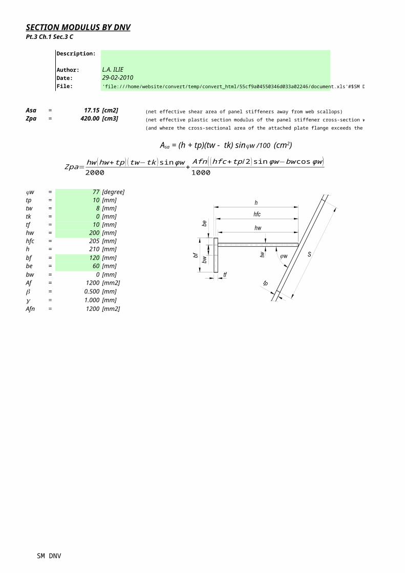
SECTION MODULUS BY DNV
Description:
Author: L.A. ILIEDate: 29-02-2010File: 'file:///tt/file_convert/55cf9a04550346d033a02246/document.xls'#$SM DNV
Asa = 17.15 [cm2] (net effective shear area of panel stiffeners away from web scallops)
Zpa = 420.00 [cm3] (net effective plastic section modulus of the panel stiffener cross-section with an inclined web)
(and where the cross-sectional area of the attached plate flange exceeds the cross-sectional area of the stiffener)
= 77 [degree]tp = 10 [mm]tw = 8 [mm]tk = 0 [mm]tf = 10 [mm]hw = 200 [mm]hfc = 205 [mm]h = 210 [mm]
bf = 120 [mm]be = 60 [mm]
bw = 0 [mm]Af = 1200 [mm2]b = 0.500 [mm]g = 1.000 [mm]
Afn = 1200 [mm2]
Pt.3 Ch.1 Sec.3 C
jw
Asa = (h + tp)(tw - tk) sinjw /100 (cm2)
Zpa=hw (hw+tp ) (tw− tk ) sinϕw2000
+Afn ( (hfc+tp /2 )sinϕw−bw cosϕw )1000
SM DNV
(and where the cross-sectional area of the attached plate flange exceeds the cross-sectional area of the stiffener)