
FOSSIL FUEL-FIRED POWER GENERATION · FOSSIL FUEL-FIRED POWER GENERATION 4 x ... Head of the Energy...
176
INTERNATIONAL ENERGY AGENCY In support of the G8 Plan of Action Case Studies of Recently Constructed Coal- and Gas-Fired Power Plants FOSSIL FUEL-FIRED POWER GENERATION CLEANER FOSSIL FUELS Please note that this PDF is subject to specific restrictions that limit its use and distribution. The terms and conditions are available online at www.iea.org/Textbase/about/copyright.asp
Transcript of FOSSIL FUEL-FIRED POWER GENERATION · FOSSIL FUEL-FIRED POWER GENERATION 4 x ... Head of the Energy...
INTERNATIONAL ENERGY AGENCY
In support of the G8 Plan of Action
Case Studies of Recently Constructed Coal- and Gas-Fired
Power Plants
FOSSIL FUEL-FIRED
POWER GENERATION
CLEANERFOSSILFUELS
Please note that this PDF is subject to specific
restrictions that limit its use and distribution.
The terms and conditions are available online at
www.iea.org/Textbase/about/copyright.asp
INTERNATIONAL ENERGY AGENCY
The International Energy Agency (IEA) is an autonomous body which was established in November 1974 within the framework of the Organisation for Economic Co-operation and Development (OECD) to implement an international energy programme.
It carries out a comprehensive programme of energy co-operation among twenty-six of the OECD thirty member countries. The basic aims of the IEA are:
n To maintain and improve systems for coping with oil supply disruptions.
n To promote rational energy policies in a global context through co-operative relations with non-member countries, industry and international organisations.
n To operate a permanent information system on the international oil market.
n To improve the world’s energy supply and demand structure by developing alternative energy sources and increasing the efficiency of energy use.
n To promote international collaboration on energy technology.
n To assist in the integration of environmental and energy policies.
The IEA member countries are: Australia, Austria, Belgium, Canada, Czech Republic, Denmark, Finland, France, Germany, Greece, Hungary, Ireland, Italy, Japan, Republic of Korea, Luxembourg, Netherlands, New Zealand, Norway, Portugal, Spain, Sweden, Switzerland, Turkey, United Kingdom and United States. The Slovak Republic and Poland are likely to become member countries in 2007/2008. The European Commission also participates in the work of the IEA.
ORGANISATION FOR ECONOMIC CO-OPERATION AND DEVELOPMENT
The OECD is a unique forum where the governments of thirty democracies work together to address the economic, social and environmental challenges of globalisation. The OECD is also at the forefront of efforts to understand and to help governments respond to new developments and concerns, such as corporate governance, the information economy and the challenges of an ageing population. The Organisation provides a setting where governments can compare policy experiences, seek answers to common problems, identify good practice and work to co-ordinate domestic and international policies.
The OECD member countries are: Australia, Austria, Belgium, Canada, Czech Republic, Denmark, Finland, France, Germany, Greece, Hungary, Iceland, Ireland, Italy, Japan, Republic of Korea, Luxembourg, Mexico, Netherlands, New Zealand, Norway, Poland, Portugal, Slovak Republic, Spain, Sweden, Switzerland, Turkey, United Kingdom and United States.The European Commission takes part in the work of the OECD.
© OECD/IEA, 2007
International Energy Agency (IEA), Head of Communication and Information Office,
9 rue de la Fédération, 75739 Paris Cedex 15, France.
Please note that this publication is subject to specific restrictions that limit its use and distribution.
The terms and conditions are available online at http://www.iea.org/Textbase/about/copyright.asp

3
FOREWORD
One of the major pathways of reducing the CO2 emissions from fossil-fired power generation is to maximise the efficiency of new plants built to meet future demand growth and for replacing older or inefficient plants. To enable the other major pathway, carbon dioxide capture and storage, it is imperative that new plants are designed and operated at highest efficiency.
At the Gleneagles Summit in July 2005, the G8 leaders invited the IEA “...to carry out a global study of recently constructed plants, building on the work of its Clean Coal Centre, to assess which are the most cost effective and have the highest efficiencies and lowest emissions, and to disseminate this information widely”.
The series of case studies outlined in this report were conducted in response to the G8 leaders’ request to ascertain what efficiency is currently achieved and at what cost in modern fossil-fired plants using different grades of fuel in different geographical areas of the world. As explained herein, efficiency of power generation depends, among other factors, on fuel quality and ambient conditions. Recent coal-fired power plants of high efficiency use pulverised coal combustion (PCC) with supercritical (very high pressure and temperature) steam turbine cycles, and so most of the case studies are drawn from these. A review of current and future applications of coal-fuelled integrated gasification combined cycle plants (IGCC) is also included, as is a case study of a natural gas-fired combined cycle plant to facilitate comparisons.
The case studies show that the technologies for reliable operation at high efficiency and very low conventional pollutant emissions from coal-fired power generation are available now at commercially acceptable cost. The report also illustrates how operational practice and innovative designs to suit local conditions can be used to improve efficiency.
The challenge to the policy makers now is to formulate measures that would enable wider deployment of these technologies globally but particularly in countries which need these most, while also encouraging operational best practice and continued technological improvement towards higher efficiency.
This report provides the technical underpinning for another report underway at the IEA assessing prospects of widespread upgrading of older coal-fired power plants in major coal using countries.
Nobuo TanakaExecutive Director
Foreword y

FOSSIL FUEL-FIRED POWER GENERATION 4x
ACKNOWLEDGEMENTS
Colin Henderson of the IEA Clean Coal Centre is the author of this report, which was prepared for the International Energy Agency by IEA Coal Research Limited, an operating agent for the IEA Clean Coal Centre.
A number of individuals assisted in the development of the case studies; they are acknowledged at the end of each of the case studies in Chapter 3. In addition, IEA Coal Research also organized separate reviews of the draft by a number of anonymous reviewers.
At the IEA, very useful comments were provided by Neil Hirst, Director of the Energy Technology Office; Antonio Pflüger, Head of the Energy Technology Collaboration Division; Nancy Turck, Chief Legal Counsel, IEA; Jean-Yves Garnier, Head of the Energy Statistics Division; and Rebecca Gaghen, Head of the Communication and Information Office.
The report was reviewed extensively at the IEA by Sankar Bhattacharya, Brian Ricketts, Jacek Podkanski and Kamel Bennaceur.
Production assistance was provided by Corinne Hayworth, Bertrand Sadin, Sophie Schlondorff and Muriel Custodio of the IEA Communication and Information Office (CIO).
Comments and queries on this report should be addressed to Dr. Sankar Bhattacharya at [email protected]

5
TABLE OF CONTENTS
EXECUTIVE SUMMARY 11
Chapter 1 INTRODUCTION 25
Chapter 2 DESIGNING FOR HIGH EFFICIENCY 33
Chapter 3 CASE STUDIES AND IGCC TECHNOLOGY REVIEW 37
y COAL-FIRED PLANT 1 – Northern Europe
Sea water cooled ultra-supercritical plant Nordjyllandsværket 3, Denmark 39
y COAL-FIRED PLANT 2 – Northern Europe
Lignite-fired, inland ultra-supercritical PCC plant Niederaussem K, Germany 50
y COAL-FIRED PLANT 3 – North America
Sub-bituminous coal-fired, inland supercritical plant Genesee 3, Canada 63
y COAL-FIRED PLANT 4 – Asia
Bituminous coal-fired, coastal ultra-supercritical plant Isogo New Unit 1, Japan 73
y COAL-FIRED PLANT 5 – Asia
Bituminous coal-fired, coastal supercritical PCC plant Younghung Thermal Power Plant, Republic of Korea 83
y COAL-FIRED PLANT 6 – Asia
Clean coal-fired, inland supercritical PCC plant Wangqu 1 and 2, China 90
y COAL-FIRED PLANT 7 – Asia
High ash bituminous coal-fired, inland PCC plant Suratgarh, India 100
y COAL-FIRED PLANT 8 – Africa
High ash bituminous coal-fired PCC plant with dry and wet cooling Majuba, South Africa 110
y NATURAL GAS-FIRED PLANT – Europe
Enfield, United Kingdom 121
y IGCC TECHNOLOGY REVIEW 129
Table of Contents y

FOSSIL FUEL-FIRED POWER GENERATION 6x
Chapter 4 REVIEW OF CASE STUDIES AND GENERAL CONCLUSIONS 141
Introduction 141
Comparison of Performance and Costs 143
Future Developments 159
General Conclusions 160
Appendix A DATA ENQUIRY QUESTIONNAIRE 163
Appendix B ACRONYMS AND ABBREVIATIONS 169
7
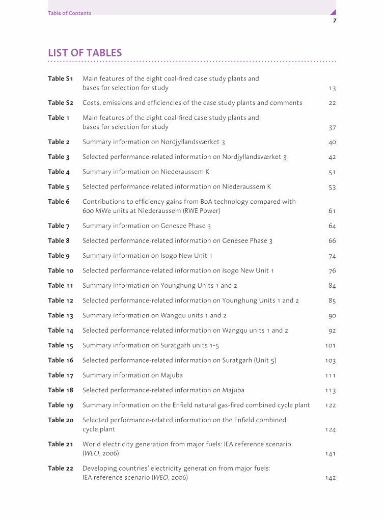
LIST OF TABLES
Table S1 Main features of the eight coal-fired case study plants and bases for selection for study 13
Table S2 Costs, emissions and efficiencies of the case study plants and comments 22
Table 1 Main features of the eight coal-fired case study plants and bases for selection for study 37
Table 2 Summary information on Nordjyllandsværket 3 40
Table 3 Selected performance-related information on Nordjyllandsværket 3 42
Table 4 Summary information on Niederaussem K 51
Table 5 Selected performance-related information on Niederaussem K 53
Table 6 Contributions to efficiency gains from BoA technology compared with 600 MWe units at Niederaussem (RWE Power) 61
Table 7 Summary information on Genesee Phase 3 64
Table 8 Selected performance-related information on Genesee Phase 3 66
Table 9 Summary information on Isogo New Unit 1 74
Table 10 Selected performance-related information on Isogo New Unit 1 76
Table 11 Summary information on Younghung Units 1 and 2 84
Table 12 Selected performance-related information on Younghung Units 1 and 2 85
Table 13 Summary information on Wangqu units 1 and 2 90
Table 14 Selected performance-related information on Wangqu units 1 and 2 92
Table 15 Summary information on Suratgarh units 1-5 101
Table 16 Selected performance-related information on Suratgarh (Unit 5) 103
Table 17 Summary information on Majuba 111
Table 18 Selected performance-related information on Majuba 113
Table 19 Summary information on the Enfield natural gas-fired combined cycle plant 122
Table 20 Selected performance-related information on the Enfield combined cycle plant 124
Table 21 World electricity generation from major fuels: IEA reference scenario (WEO, 2006) 141
Table 22 Developing countries’ electricity generation from major fuels: IEA reference scenario (WEO, 2006) 142
Table of Contents y

FOSSIL FUEL-FIRED POWER GENERATION 8x
Table 23 Costs, emissions and efficiencies of the case study plants 144
Table 24 Design and operating efficiencies of the coal-fired case study plants adjusted nominally to a basis of common cooling water inlet temperature of 20°C, coal moisture of 10% as-received, ash of 10-25% and inclusion of FGD plus SCR, %, net, HHV basis 145
Table 25 Temperature of flue gases after final heat extraction and estimated efficiency effects 146
Table 26 Approximate specific carbon dioxide emissions, kg/MWhso 150
Table 27 Treatment of specific capital cost data to arrive at indicative overnight costs 151
Table 28 Construction time for the plants (months) 155
Table 29 Estimated operating costs for different types of plants based on questionnaires and IEA Clean Coal Centre estimates ($ and cents are US currency) 156
Table 30 Nominal generating costs – OECD location (US cents/kWh) 157
Table 31 Nominal generating costs – non-OECD location (US cents/kWh) 158
9
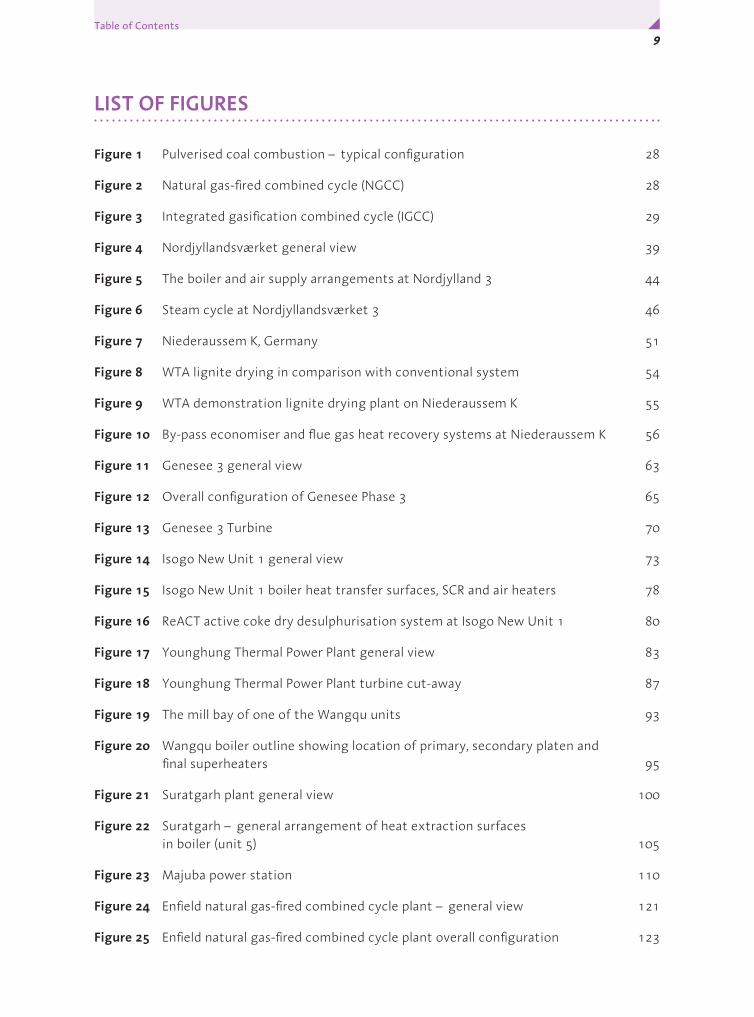
LIST OF FIGURES
Figure 1 Pulverised coal combustion – typical configuration 28
Figure 2 Natural gas-fired combined cycle (NGCC) 28
Figure 3 Integrated gasification combined cycle (IGCC) 29
Figure 4 Nordjyllandsværket general view 39
Figure 5 The boiler and air supply arrangements at Nordjylland 3 44
Figure 6 Steam cycle at Nordjyllandsværket 3 46
Figure 7 Niederaussem K, Germany 51
Figure 8 WTA lignite drying in comparison with conventional system 54
Figure 9 WTA demonstration lignite drying plant on Niederaussem K 55
Figure 10 By-pass economiser and flue gas heat recovery systems at Niederaussem K 56
Figure 11 Genesee 3 general view 63
Figure 12 Overall configuration of Genesee Phase 3 65
Figure 13 Genesee 3 Turbine 70
Figure 14 Isogo New Unit 1 general view 73
Figure 15 Isogo New Unit 1 boiler heat transfer surfaces, SCR and air heaters 78
Figure 16 ReACT active coke dry desulphurisation system at Isogo New Unit 1 80
Figure 17 Younghung Thermal Power Plant general view 83
Figure 18 Younghung Thermal Power Plant turbine cut-away 87
Figure 19 The mill bay of one of the Wangqu units 93
Figure 20 Wangqu boiler outline showing location of primary, secondary platen and final superheaters 95
Figure 21 Suratgarh plant general view 100
Figure 22 Suratgarh – general arrangement of heat extraction surfaces in boiler (unit 5) 105
Figure 23 Majuba power station 110
Figure 24 Enfield natural gas-fired combined cycle plant – general view 121
Figure 25 Enfield natural gas-fired combined cycle plant overall configuration 123
Table of Contents y

FOSSIL FUEL-FIRED POWER GENERATION 10x
Figure 26 Gas turbine at Enfield 125
Figure 27 Normalised operating efficiencies of supercritical case study plants compared with elsewhere 148
Figure 28 Calculated overnight specific capital cost versus unit size, coal-fired case study units in OECD locations 153
Figure 29 Adjusted specific plant costs versus main steam temperature 153
Figure 30 Adjusted specific plant costs versus normalised efficiency 154

11Executive Summary y
EXECUTIVE SUMMARY
Background
One of the ways of substantially reducing the emissions of CO2 from fossil fired power generation is to maximise the efficiency of new plants being installed to meet future demand growth and for replacing inefficient capacity. This series of case studies was conducted to show what is achieved now in modern plants in different parts of the world. It arose from a request to the IEA in the Plan of Action regarding climate change that emerged from the G8 Summit communiqué in July 2005 to:
“… carry out a global study of recently constructed plants, building on the work of its Clean Coal Centre, to assess which are the most cost effective and have the highest efficiencies and lowest emissions, and to disseminate this information widely …” .
Recent coal-fired power plants of high efficiency use pulverised coal combustion (PCC) with supercritical (very high pressure and temperature) steam turbine cycles, and so most of the case studies are drawn from these. They were selected from different geographical areas, because local factors influence attainable efficiency. A review of current and future applications of coal-fuelled integrated gasification combined cycle plants (IGCC) is also included. Although these are small in number and not recently constructed (one is being constructed currently) so that there are greater cost and other uncertainties, the technology could form the foundation of many future power stations, with its very low conventional emissions and potential advantages for CO2 capture. It should be noted that there is more uncertainty in IGCC cost and performance projections as the commercial ordering of coal-fuelled IGCC as a complete system for power generation by utilities has yet to occur. There is also a case study of a natural gas-fired combined cycle plant, included to facilitate comparisons.
Work method
Data gathering by questionnaire was followed up with plant visits by IEA CCC personnel. Information was also obtained from published sources. Some of the data, especially on costs, could not be supplied by all owners because of confidentiality considerations. Data gathering was carried out during 2006 and followed by analysis and report preparation. The final report does not include all the detailed information. The intention has been to identify and summarise important messages that emerge.
Case study plants
A list of the coal-fired plants, with boiler and turbine suppliers, some key features and the bases of the selections, is given in Table S1. The two plants

FOSSIL FUEL-FIRED POWER GENERATION 12x
in Europe are a cold sea water cooled plant fired on internationally-traded, bituminous coals (Nordjyllandsværket 3, Denmark) and an inland, lignite-fired unit in Germany (Niederaussem K). The case study plant in North America is the first modern supercritical unit and fires sub-bituminous coal. In Asia, three plants are included. In Japan, Isogo New Unit 1 has the highest steam conditions in the world among currently operating sliding pressure units and very low emissions. The first two units at Younghung Thermal Power Plant in the Republic of Korea illustrate the progression toward higher steam conditions ongoing in that country, and the first two units at Wangqu in China mark a development in firing low volatile coals in supercritical units. The subcritical plants in India, at Suratgarh, and South Africa, at Majuba, cover high ash coal burning in difficult locations, with Majuba illustrating the use of dry cooling. Experience will be relevant to future supercritical plants in these countries. The study findings are summarised below.
Nordjylland 3, DenmarkThe 400 MWe Unit 3 at Nordjylland power station, owned by Vattenfall, is a sea water cooled ultra-supercritical unit fired on internationally-traded, bituminous coals. Opened in 1998, the plant is situated near the town of Aalborg, which it also supplies with heat. In power-only mode, net efficiency is 47%, on a fuel LHV basis* (44.9% on an HHV basis), so Nordjylland 3 is the most efficient coal-fired unit in the world. The high efficiency comes from use of a double reheat steam cycle at very high conditions (29 MPa/582°C/580°C/580°C) plus a low condenser pressure from the availability of cold sea water for cooling. The steam conditions took full advantage of newly available materials when the plant was designed but also necessitated the use of flue gas re-circulation and advanced water treatment as well as care in start-up to ensure integrity of boiler components.
Airborne emissions are very low. For NOx control, the tangentially fired boiler has low-NOx burners, overburner air and over-fire air as well as a selective catalytic reduction (SCR) unit. For dust removal there are electrostatic precipitators (ESPs,) and a limestone-gypsum flue gas desulphurisation (FGD) system achieves extremely low SO2 residual levels. Virtually all solid by-products are utilised and calcium chloride liquor from the FGD waste stream will shortly be sold for road de-icing.
No economic information was available from the plant operators. According to DONG Energy (who now own ELSAM, the previous owners of the plant), the contracting strategy was owner design with multi-contract procurement. Information on the current cost of an 800 MWe ultra-supercritical plant from Siemens indicates that it would be around 1500 USD/kWso in 2006, excluding owner’s costs or interest during construction.
*The calculation of fuel LHV used as the basis of the LHV efficiency throughout this publication includes subtraction of the latent heat of the water vapour formed from evaporation of the moisture originally present in the coal as well as that of the water vapour formed from combustion of the coal hydrogen.

13Executive Summary y
Tabl
e S1
• M
ain
feat
ures
of t
he e
ight
coa
l-fire
d ca
se s
tudy
pla
nts
and
base
s fo
r sel
ecti
on fo
r stu
dy
Plan
tSi
ting
Coal
MW
e ne
tBo
iler
geom
etry
Mai
n su
pplie
rs:
boile
r; tu
rbin
eU
ltra
-sup
er-,
Supe
r- or
su
b-cr
it
Stea
m c
ondi
tion
sM
Pa/
°C/
°C(/
°C)
Why
sel
ecte
d
Euro
pe –
Den
mar
k:N
ordj
ylla
ndsv
ærk
et 3
coas
tal
inte
rnat
iona
l38
4to
wer
FLS
milj
o/BW
E, A
albo
rg
Indu
strie
s, Vo
lund
Ene
rgy
Syst
ems;
GEC
Als
thom
(n
ow A
lsto
m)
USC
29/
582/
580/
58
0M
ost e
ffici
ent c
oal p
lant
; do
uble
-rehe
at;
very
low
em
issi
ons
Euro
pe –
Ger
man
y:N
iede
raus
sem
Kin
land
ligni
te96
5to
wer
EVT
(tod
ay A
lsto
m),
Babc
ock
and
Stei
nmül
ler
(tod
ay H
PE);
Siem
ens
USC
27/
580/
600
Lign
ite; t
op e
ffici
ency
lig
nite
pla
nt; l
igni
te d
rier
dem
onst
ratio
n
Nor
th A
mer
ica
– Ca
nada
:G
enes
ee 3
inla
ndsu
b-bi
tum
inou
s45
02-
pass
Babc
ock-
Hita
chi
S/C
25/
570/
570
Sub-
bitu
min
ous
coal
; fir
st s
lidin
g pr
essu
re S
/C
Nor
th A
mer
ica
Asi
a –
Japa
n:Is
ogo
New
Uni
t 1co
asta
lin
tern
atio
nal
568
tow
erIH
I; Fu
ji El
ectr
ic
(Sie
men
s)U
SC25
/60
0/61
0Ve
ry h
igh
stea
m p
aram
eter
s; ve
ry lo
w e
mis
sion
s; ac
tivat
ed
coke
rege
nera
ble
FGD
Asi
a –
Kore
a:Yo
ungh
ung
coas
tal
inte
rnat
iona
l2x
774
tow
erD
oosa
n H
eavy
Indu
strie
s &
Con
stru
ctio
n Co
.S/
C25
/56
6/56
6M
ost r
ecen
t and
larg
est
coal
-fire
d un
its in
Kor
ea
Asi
a –
Chin
a:W
angq
u 1,
2in
land
Chin
ese
lean
2x60
02-
pass
Doo
san
Babc
ock;
Hita
chi
S/C
24/
566/
566
Loca
tion;
wal
l-firin
g of
low
-vo
latil
e co
al w
ith lo
w N
Ox
Asi
a –
Indi
a:Su
ratg
arh
1-5
inla
nd~
30%
ash
5x22
72-
pass
BHEL
Dru
msu
b-cr
it15
/54
0/54
0Lo
catio
n; h
igh
ash
coal
; dru
m
boile
r
Afr
ica
– So
uth
Afr
ica:
Maj
uba
1-6
inla
nd~
30%
ash
3x61
2 (d
ry)
3x66
9 (w
et)
tow
erSt
einm
ülle
r; A
lsto
mon
ce-th
roug
h su
b-cr
it17
/54
0/54
0Lo
catio
n; d
ry v
ersu
s w
et
cool
ing;
hig
h as
h co
al, o
nce-
thro
ugh
sub-
criti
cal b
oile
r
USC
: ul
tra-su
perc
ritic
al (
stea
m te
mpe
ratu
res
of 5
80°C
and
abo
ve)
S/C:
su
perc
ritic
al

FOSSIL FUEL-FIRED POWER GENERATION 14x
This impressive unit was a result of initiatives by Danish utilities to move to much higher efficiency plants of high flexibility by working with major suppliers on designs that are practical and economic at high steam conditions. Danish engineers are continuing to look at innovative means to reach still better performance in future plants.
Niederaussem K, Germany
Niederaussem K, owned by RWE Power, is a 1000 MWe ultra-supercritical lignite-fired unit near Cologne. Net efficiency is 43.2%, on a fuel LHV basis (37% on an HHV basis). The unit is the most efficient lignite-fired plant in the world. Niederaussem K opened in 2002, and there are two further units based on the technology under construction at a neighbouring RWE power station site at Neurath.
In addition to the advanced steam conditions (27.5 MPa/580°C/600°C), there are other features that have been used for very high efficiency. Among these are a complex water circuit to exploit a unique heat recovery system downstream of the main economiser and a flue gas cooler for final heat recovery. The condenser pressure has also been made low by incorporating an unusually tall cooling tower. Although there were a few early difficulties with materials in parts of the boiler, these were solved by use of newer alloys.
NOx emissions from the boiler are low from the use of wall-mounted lignite-specific low-NOx burners and other fuel and air staging arrangements, so there is no downstream flue gas NOx control equipment. Electrostatic precipitators collect fly ash, and a wet FGD unit desulphurises the emerging flue gas.
The investment cost was around 1175 USD/kWso in 2002, including interest during construction and owner’s costs, and construction took 48 months.
The efficiency is very good for a plant firing 50-60% moisture content lignite fuel. A demonstration plant for pre-drying part of the lignite fuel feed using low grade heat is being installed to enable even higher efficiencies. The new units at Neurath will have slightly higher steam conditions and a simpler cycle, but include many of the features of Niederaussem K.
Genesee 3, Canada
Genesee 3, opened in March 2005, is the first sliding pressure coal-fired supercritical unit to be commissioned in North America. The 450 MWe unit, located 75 km from Edmonton, is jointly owned by EPCOR and TransAlta Energy Corporation. It operates on a sub-bituminous Albertan coal. Steam parameters (25 MPa/570C°/568°C) were chosen to maximise efficiency while minimising risk and net efficiency is over 41% on an LHV basis (40% on an HHV basis). The overall configuration consists of a two-pass supercritical boiler, a single reheat supercritical cycle with eight stages of feedwater heating, a spray-dry flue gas desulphurisation unit, and a bag filtration system.

15Executive Summary y
Genesee 3 had to be suitable for flexible operation in a market-oriented environment without compromising on efficiency or environmental performance. The design SO2 emissions are less than half the normal legislated level and emissions of NOx are much better than required through use of advanced low-NOx burners and over-fire air. The fabric filtration unit takes the concentration of particulates down to better than design.
The cost of Genesee phase 3 was approximately 1100 USD/kWso in 2005, excluding interest during construction or owners costs, and construction took 36 months. The power generating and emission control equipment was established through a single EPC contract.
The sliding pressure design used here allows economically competitive, flexible plants that will be suited to de-regulated environments elsewhere in North America. It has been a low-risk way of achieving high efficiency and environmental performance on sub-bituminous coals. After construction of a sister unit at a neighbouring TransAlta power generation site, later plants are likely to move to higher steam parameters, following the success of this and similar units currently being constructed in Canada and the USA.
Isogo New Unit 1, Japan
Isogo New Unit 1 is a sea water cooled, 600 MWe ultra-supercritical unit, owned by Electric Power Development Co. (J-POWER). It is located at Yokohama City, 25 km from Tokyo. The plant, opened in April 2002, burns Japanese and internationally-traded bituminous coals and some sub-bituminous coal. Very high steam conditions give a good efficiency of over 42% net, LHV basis (40.6%, HHV basis) at this rather warm sea water cooled site. Advanced steam parameters (25 MPa/600°C/610°C) were made possible by the availability of recently developed steels. The configuration includes a once-through wall-fired tower boiler fitted with combustion measures for low-NOx, a single reheat advanced supercritical steam turbine cycle, with eight stages of feedwater heating, an SCR, ESPs, and a dry FGD.
Isogo New Unit 1’s environmental performance is very impressive. The plant easily meets extremely tight emissions levels on NOx, dust and oxides of sulphur. The flue gas desulphurisation system is a dry regenerable process which uses activated coke to capture the SO2. It consumes less power and much less water than wet systems. J-POWER are marketing the technology under the name of ReACT as a multi-pollutant control system for oxides of sulphur, NOx and particulates, as well as heavy metals such as mercury. Virtually all solid by-products are utilised at Isogo.
The contracting strategy was to use owner design basic specification and the approximate capital cost was 1800 USD/kWso (2006), based on Isogo New Units 1 and 2 (latter not yet completed), including interest during construction and owner’s costs. Construction time was 66 months.
Isogo New Unit 1 is a flagship PCC plant. It uses the highest steam parameters in the world for a modern sliding pressure system, and close to zero emissions

FOSSIL FUEL-FIRED POWER GENERATION 16x
of conventional pollutants have been achieved. The Isogo New Unit 2, construction of which commenced in October 2005, will have even higher steam conditions (25MPa/600°C/620°C) and use the ReACT system for multi-pollutant control.
Younghung Thermal Power Plant, Republic of Korea
Younghung Thermal Power Plant, owned by the Korean South-East Power Company (KOSEP), is the newest coal-fired plant in Korea. The first two units, opened in 2004, have supercritical steam parameters of 24.7 MPa/566°C/566°C. Younghung is located at Incheon, approximately 50 km from Seoul. The units are sea water cooled, rated each at 800 MWe, and fire internationally-traded bituminous coals. These are the largest coal-fired units to be built in Korea to date and have used higher steam conditions than previous plants in the country. A single reheat supercritical steam turbine system of conventional configuration with eleven stages of feedwater heating is used and design net efficiency is 43% on an LHV basis (41.9%, HHV basis). The aim is to establish twelve units on the site. Construction of Units 3 and 4 is in progress. These will be similar, but use higher steam temperatures of 593°C.
A combination of environmental control systems gives very good environmental performance. Low-NOx combustors and air staging in the boiler provide initial NOx minimisation, and an SCR unit removes much of the remaining NOx. Particulates are removed by ESPs, and 60% of the ash is utilised. A limestone/gypsum FGD system removes SO2. By-product gypsum is sold to the construction industry.
The plant specific capital cost was 993 USD/kWso in 2003, but the basis is uncertain. Construction time was 64 months.
Thus, low emissions of conventional pollutants have been achieved in a cost-effective plant using conventional commercial systems. In Korea, plant designs are now moving toward higher conditions quite rapidly, and succeeding unit additions at Younghung will have progressively higher steam parameters.
Wangqu 1 and 2, China
Wangqu opened in 2006, and is owned by Shanxi Lujin Wangqu Power Generation Co. Ltd. It is at an inland location, 2 km from Lucheng City near Changzhi. The two new 600 MWe (nominal) units, completed in 2006, have a design net efficiency of over 41% on an LHV basis (40%, HHV basis). They represent a major step forward in being among the first wall-fired supercritical boilers to operate successfully using lean coals (10 to 20% V.M.) by employing advanced low NOx burners together with high velocity over-fire air. Due to pressure to send the best coals to steelmaking, China’s power stations increasingly need to burn such coals.

17Executive Summary y
Each unit has a two-pass supercritical boiler, a single reheat supercritical cycle with eight stages of feedwater heating, ESPs and a wet FGD. Steam parameters are 24.2 MPa/566°C/566°C, chosen to minimise risk, while giving good performance.
The combustion system has been developed to meet Chinese legislation on NOx emissions from new lean coal-fired plant even at low loads with good combustion efficiency. The SO2 removal design efficiency at the plant is also good.
The contracting strategy used by the client was owner design specification with competitive bidding. The installation cost was approximately 580 USD/kWso in 2006. This figure is understood to exclude owner’s costs and interest during construction. Construction time was 30 months.
These units are a good example of the way China is moving rapidly to improve the efficiency and emissions of its power plants by ordering high-performing international technology with licensing agreements to enable the country to use its own manufacturing capabilities for future plants. Two further identical 600 MWe units at the site will be air cooled, as Shanxi province has a water shortage problem.
Suratgarh, India
Suratgarh thermal power plant consists of five 250 MWe subcritical units commissioned between 1998 and 2003. It is owned by the Rajasthan State Electricity Board and is situated in the northern part of Rajasthan in the Ganganagar district on the edge of the Thar/Indian desert. A single reheat subcritical steam turbine system of conventional configuration with six stages of feedwater heating is used for each unit, and design efficiency is 37.1% on an LHV basis (35.1%, HHV basis). Steam parameters are 15.8 MPa/540°C/540°C. The units are water cooled, with mechanical draught cooling towers. Ambient conditions here result in a higher condenser pressure (10.5 kPa) than encountered in more temperate regions.
High efficiency ESPs are fitted for particulates control, and tangential firing and over-fire introduction of secondary air are used for NOx control. There is no SCR or FGD. Ash utilisation has grown steadily, and Suratgarh plans achieving 100% utilisation by 2010.
The units were designed to use indigenous coals of ash content 45% but the fuel used is now a blend, including some Chinese coal, to keep to around 30% in line with Government requirements to use maximum 34% ash coal. This is still high by world standards. Other challenges were associated with the desert environment giving difficult site ground conditions and water quality variations. Low rainfall necessitated construction of a reservoir for 21 days’ operation. Air intakes are designed to avoid ingress of sand during sandstorms.
The plant specific capital cost was approximately 822 USD/kWso in 2002, but the basis of this was uncertain. Construction time for one unit was 39 months.
FOSSIL FUEL-FIRED POWER GENERATION 18x
The thermal efficiency is inevitably penalised by the coal quality as well as the local conditions and the use of a subcritical cycle, but future, higher efficiency supercritical units will be able to build on the experience gained.
Majuba, South Africa
Majuba is another plant in an area of water shortage firing high ash coal, in this case of around 30% ash content and of slagging and fouling propensity. The plant is owned by Eskom and is situated near Amersfoort in Mpumalanga. The coal for the 4110 MWe power station is brought from collieries in the Witbank area of Mpumalanga. Majuba consists of six units of over 600 MWe. The first opened in April 1996 and the others followed at yearly intervals.
Each unit uses a subcritical once-through tower boiler of steam parameters 17.2 MPa/540°C/540°C and a single reheat subcritical steam turbine. Units 1-3 employ air cooling and units 4-6 have water cooling. Six stages of feedwater heating are used for both types. The design efficiencies of the dry-cooled and wet-cooled units are around 35% and 37% net on an LHV basis (33.8% and 35.7%, HHV basis), respectively.
Low-NOx burners give control of NOx. Staggered burner geometry is used to minimise slagging. There is no SCR or FGD. Fabric filtration systems remove particulates.
In the dry-cooled condensers, steam from the turbines is condensed inside tubing, across which air is blown. Condensing performance is very dependent on ambient temperature, so unit output and efficiency vary considerably with season. The wet cooled units have conventional condensers and natural draught cooling towers. Wet cooling was selected for these units for economic reasons.
The specific capital cost of Majuba was approximately 410 USD/kWso in 2001, including interest during construction and owner’s costs. The plant is currently two-shifting and performing well, despite being intended for base load use.
Dry cooled units are less efficient than conventional systems and efficiency is also affected by the use of a subcritical cycle. Dry cooling would be considered for future plants, depending on water availability. Eskom is understood to be currently in the bidding stage for 3x660 MW supercritical power plants.
Natural gas-fired plant: Enfield, United Kingdom
The Enfield Energy Centre combined cycle plant in northeast London opened for commercial production in 2002 and is currently owned by E-ON. It is a 400 MWe system, based on a reheat gas turbine and reheat steam cycle. The design efficiency is 58% net on an LHV basis (52%, HHV basis). The combined cycle turbine is currently offered by the manufacturer with an efficiency of 58.5% (LHV).

19Executive Summary y
Enfield employs Alstom’s GT26B gas turbine, which has two combustion zones, with a high pressure expansion turbine between them and a low pressure turbine after the second combustor. The system was developed to give high efficiency without the need for the highest turbine inlet temperatures. The hot exhaust gases raise steam at three pressure levels for a subcritical reheat steam turbine, which is coupled to the same generator. The steam cycle here has an air cooled condenser.
The gas turbine uses a sequential annular combustion system and low-NOx burners to keep NOx production low without needing an SCR unit.
NGCC projects are lower in investment requirements than coal-fired projects in OECD locations. In this case, the total project cost was around USD350 million, or around 950 USD/kWso in 1999. The overnight cost will have been considerably lower. Gas turbine combined cycle projects have short construction times, and here it was 22 months. Enfield currently operates on a flexible, two-shift basis but efficiency is still high at 52% (LHV).
This plant highlights a continuing drive by manufacturers to move the technology on to higher future performance through innovation. High efficiency and lower capital requirements mean natural gas-fired combined cycles will continue to be specified for many power generation projects where natural gas is available.
IGCC technology review
Net efficiency for IGCC in existing plants is around 40-43% on an LHV basis (around 38-41%, HHV basis). Recent gas turbines would enable this to be bettered and future developments should take efficiencies beyond 50% on an LHV basis. Emissions are low, and mercury removal will be cheaper than for PCC. The specific investment cost of IGCC is about 20% higher than that of PCC. There is however more uncertainty in IGCC costs as there are no recently built coal-fuelled IGCC plants and the existing ones were constructed as demonstrations. Availabilities have also not yet reached the demonstrated level of operating PCC units. Suppliers have plans to bring the capital cost to within 10% of that of PCC. Note that, while there are competitive pressures, the capital costs being cited for many power projects have risen sharply recently because of increases in energy prices and their impacts on steel and concrete costs.
There are two demonstration plants in the EU. NUON’s plant, at Buggenum in Holland, is a 250 MWe system, based on Shell gasification and a Siemens V94.2 gas turbine. It now operates as a commercial plant on imported coals with good availability and a net efficiency of 43% (LHV). The other is ELCOGAS’s plant at Puertollano in Spain, a 300 MWe system based on the similar Prenflo gasifier and a Siemens V94.3 gas turbine. It uses a high ash coal/high sulphur petcoke mixed fuel and has a net efficiency of 42% (LHV). Both had initial problems in firing syngas and needed turbine combustor modifications. Both have highly integrated systems, which have proved to be rather inflexible. A 1200 MWe plant at another site is planned by NUON.

FOSSIL FUEL-FIRED POWER GENERATION 20x
IGCC plants currently operating in the USA are the Tampa Electric Polk project and the Wabash River coal gasification project, both constructed under the US DOE CCT Program. The 250 MWe Polk project uses a GE gasifier and GE 7FA gas turbine. The net efficiency was 35.4% on an HHV basis (36.7%, LHV basis) on coal feed. The 260 MWe Wabash River project uses ConocoPhillips E-Gas technology with a GE 7FA turbine and an existing steam turbine and has a net efficiency of over 38% on an HHV basis (40%, LHV basis). Both US plants are less integrated than the EU ones although some gas turbine air extraction has recently been incorporated at the Polk plant. The gas turbines performed well at both but there were some other difficulties. Both plants now operate commercially, although their availabilities are understood to be lower than the best in class operating supercritical PCC plants in the USA. A CCPI demonstration of the transport gasifier is to be constructed in Florida.
In Japan, the Clean Coal Power R&D Co., Ltd. (CCP) is constructing a 250 MWe IGCC demonstration project, due to start operation in 2007, at Iwaki City, based on the MHI air-blown entrained gasifier and an MHI gas turbine.
IGCC reference plant designs of 600 MWe have been developed by supplier groupings to encourage market uptake by driving down the cost and providing full single-point guarantees. Examples are those from GE-Bechtel and Siemens with ConocoPhillips. Some projects likely to use these include:
y Duke Energy, Edwardsport, Indiana – GE-Bechtel
y AEP, Meigs County, Ohio and Mason County, W. Virginia – GE-Bechtel
y Mesaba Energy Project, Minnesota – ConocoPhillips E-Gas (CCPI Demo)
With IGCC now available as a commercial package, more orders could follow as utilities see the cost decreasing and availability improving. It may still be necessary for subsidies or incentives to cover the higher cost compared with PCC.
IGCC fits well with CO2 capture and storage and there are projects planned in several countries, including Canada, Australia, Germany, the UK, in addition to the US Government FutureGen and European Commission Hypogen initiatives and the GreenGen project in China. Inclusion of CO2 capture and storage will reduce efficiency but the generation cost may be lower than for CO2 capture on PCC.
Conclusions
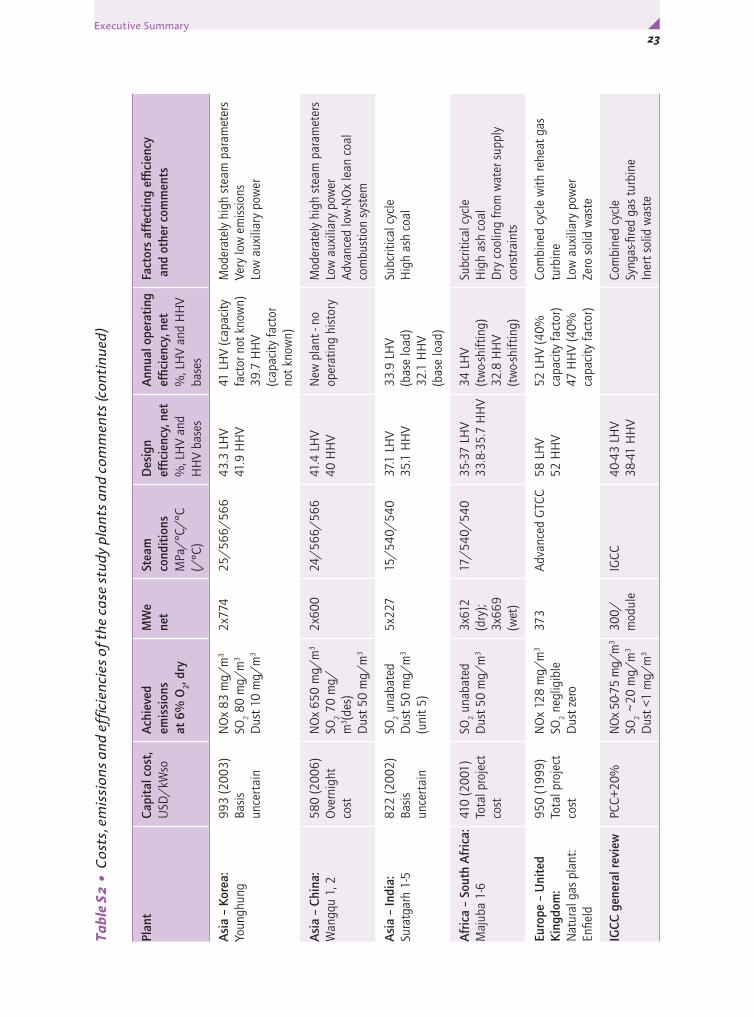
Table S2 collects together the case studies with a summary of costs, emissions and efficiencies.
In the near future, leading edge supercritical pulverised coal technology in the EU and Japan will continue gradually to move to higher steam conditions, with in some cases simplification of cycles, in others, more complex systems. The current state-of-the-art for modern, sliding pressure-capable PCC boilers is 600°C main steam and 620°C reheat at the turbine. In other regions there

21Executive Summary y
will be a follow-up move through increasing conditions while keeping just behind the state-of-the-art in order to take advantage of the experience in the new plants, while minimising risk. Although even higher temperatures have been used in the past on early supercritical designs in the USA and elsewhere, these had availability difficulties and were not competitive. In due course, leading edge plant is likely to be built in all locations.
In some countries, such as India and China, subcritical plants will probably be built in addition to supercritical units for a while. Local manufacturing bases for current plant are now capable of supplying supercritical technology so there will be movement toward the most advanced steam conditions. Other countries, not yet using or building supercritical technology, will likely begin orders at some point within the next few years. The UK, Australia and South Africa are examples.
Advanced developments in natural gas-fired gas turbines will take the efficiencies of these systems to even higher levels, maintaining their strong presence for new power projects. Developments in gas turbines will benefit commercial offerings for turbines in coal IGCC. With IGCC now available as a commercial package, orders should follow, probably aided at first through market entry incentives.
At some point, it looks highly likely that fossil-fired plants will capture and store their CO2 emissions. CO2 capture will reduce efficiency markedly, so there will be a continuing need to use innovations such as those identified in these case studies. Future very high temperature PCC systems employing superalloys should enable power generation efficiencies with CO2 capture to be comparable with those of current non-capture plants. High temperature hydrogen gas turbines and new CO2 separation methods should give IGCC with CO2 capture systems of similar performance, so both combustion-based and gasification-based platforms are likely to be important in the future.
The following main points have emerged from the case studies and subsequent analysis of results:
y New PCC projects use S/C or USC conditions as a matter of routine to achieve high efficiency;
y USC and S/C PCC systems are available for a wide range of coal types;
y Use of new materials has been important in achieving the high efficiency and reliability;
y Complex thermodynamic cycles have evolved to enhance efficiency further;
y Heat extraction to low temperatures has been demonstrated using non-metallic components in heat exchangers;
y Siting helps efficiency;
y Flexibility is no longer a problem in S/C or USC;
y A wide range of coal types can be burned in PCC systems;

FOSSIL FUEL-FIRED POWER GENERATION 22x
Tabl
e S2
• C
osts
, em
issi
ons
and
effic
ienc
ies
of th
e ca
se s
tudy
pla
nts
and
com
men
ts
Plan
tCa
pita
l cos
t, U
SD/
kWso
A
chie
ved
emis
sion
sat
6%
O2,
dry
MW
e ne
tSt
eam
co
ndit
ions
MPa
/°C
/°C
(/
°C)
Des
ign
effic
ienc
y, n
et%
, LH
V an
d H
HV
base
s
Ann
ual o
pera
ting
ef
ficie
ncy,
net
%, L
HV
and
HH
V ba
ses
Fact
ors
affe
ctin
g ef
ficie
ncy
and
oth
er c
omm
ents
Euro
pe –
Den
mar
k:N
ordj
ylla
ndsv
ærk
et 3
1500
(200
6)
for n
ew
800
MW
eex
clud
ing
owne
rs c
osts
or
IDC
NO
x 14
6 m
g/m
3
SO2 1
3 m
g/m
3
Dus
t 18
mg/
m3
384
29/
582/
580/
58
047
LH
V (n
o he
at lo
ad)
44.9
HH
V (n
o he
at lo
ad)
47 L
HV
(not
ann
ual)
44.9
HH
V (n
ot a
nnua
l)
Hig
h st
eam
par
amet
ers
Cold
sea
wat
er c
oolin
gD
oubl
e re
heat
Low
aux
iliar
y po
wer
Extr
emel
y lo
w e
mis
sion
sN
o so
lid w
aste
for d
ispo
sal
Euro
pe –
Ger
man
y:N
iede
raus
sem
K11
75 (2
002)
Tota
l pro
ject
co
st
NO
x 13
0 m
g/m
3
SO2 <
200
mg/
m3
Dus
t <50
mg/
m3
965
27/
580/
600
43.2
LH
V37
HH
V43
.2 L
HV
(bas
e lo
ad)
37 H
HV
(bas
e lo
ad)
Lign
ite fu
el, 5
0-60
% m
oist
ure
cont
ent
Hig
h st
eam
par
amet
ers
Larg
e co
olin
g to
wer
for l
ow
cond
ense
r pre
ssur
eIn
nova
tive
heat
reco
very
sys
tem
sLo
w a
uxili
ary
pow
er
Nor
th A
mer
ica
– Ca
nada
:G
enes
ee 3
1100
(200
5)
Ove
rnig
ht
cost
NO
x 17
0 m
g/m
3
SO2 2
95 m
g/m
3
Dus
t 19
mg/
m3
450
25/
570/
570
41.4
LH
V40
HH
V41
LH
V (b
ase
load
)39
.6 H
HV
(bas
e lo
ad)
Mod
erat
ely
high
ste
am p
aram
eter
sLo
w a
uxili
ary
pow
erFi
rst N
Am
eric
an s
lidin
g pr
essu
re
supe
rcrit
.Su
b-bi
tum
inou
s co
al
Asi
a –
Japa
n:Is
ogo
New
Uni
t 118
00 (2
006)
Tota
l pro
ject
co
st in
cl N
ew
Uni
t 2 u
nder
co
nstr
uctio
n
NO
x 20
mg/
m3
SO2 6
mg/
m3
Dus
t 1 m
g/m
3
568
25/
600/
610
42 L
HV
40.6
HH
V42
LH
V (b
ase
load
)40
.6 H
HV
(bas
e lo
ad)
Hig
h st
eam
par
amet
ers
Mod
erat
ely
war
m s
ea w
ater
coo
ling
Low
aux
iliar
y po
wer
Low
pow
er d
eman
d FG
DEx
trem
ely
low
em
issi
ons
No
solid
was
te fo
r dis
posa
l
23Executive Summary y
Plan
tCa
pita
l cos
t, U
SD/
kWso
A
chie
ved
emis
sion
sat
6%
O2,
dry
MW
e ne
tSt
eam
co
ndit
ions
MPa
/°C
/°C
(/
°C)
Des
ign
effic
ienc
y, n
et%
, LH
V an
d H
HV
base
s
Ann
ual o
pera
ting
ef
ficie
ncy,
net
%, L
HV
and
HH
V ba
ses
Fact
ors
affe
ctin
g ef
ficie
ncy
and
oth
er c
omm
ents
Asi
a –
Kore
a:Yo
ungh
ung
993
(200
3)Ba
sis
unce
rtai
n
NO
x 83
mg/
m3
SO2 8
0 m
g/m
3
Dus
t 10
mg/
m3
2x77
425
/56
6/56
643
.3 L
HV
41.9
HH
V41
LH
V (c
apac
ity
fact
or n
ot k
now
n)39
.7 H
HV
(cap
acity
fact
or
not k
now
n)
Mod
erat
ely
high
ste
am p
aram
eter
sVe
ry lo
w e
mis
sion
sLo
w a
uxili
ary
pow
er
Asi
a –
Chin
a:W
angq
u 1,
258
0 (2
006)
Ove
rnig
ht
cost
NO
x 65
0 m
g/m
3
SO2 7
0 m
g/m
3 (de
s)D
ust 5
0 m
g/m
3
2x60
024
/56
6/56
641
.4 L
HV
40 H
HV
New
pla
nt -
no
oper
atin
g hi
stor
y M
oder
atel
y hi
gh s
team
par
amet
ers
Low
aux
iliar
y po
wer
Adv
ance
d lo
w-N
Ox
lean
coa
l co
mbu
stio
n sy
stem
Asi
a –
Indi
a:Su
ratg
arh
1-5
822
(200
2)Ba
sis
unce
rtai
n
SO2 u
naba
ted
Dus
t 50
mg/
m3
(uni
t 5)
5x22
715
/54
0/54
037
.1 L
HV
35.1
HH
V33
.9 L
HV
(bas
e lo
ad)
32.1
HH
V (b
ase
load
)
Subc
ritic
al c
ycle
Hig
h as
h co
al
Afr
ica
– So
uth
Afr
ica:
Maj
uba
1-6
410
(200
1)
Tota
l pro
ject
co
st
SO2 u
naba
ted
Dus
t 50
mg/
m3
3x61
2 (d
ry);
3x66
9 (w
et)
17/
540/
540
35-3
7 LH
V33
.8-3
5.7
HH
V34
LH
V (t
wo-
shift
ing)
32.8
HH
V (t
wo-
shift
ing)
Subc
ritic
al c
ycle
Hig
h as
h co
alD
ry c
oolin
g fro
m w
ater
sup
ply
cons
trai
nts
Euro
pe –
Uni
ted
Kin
gdom
:N
atur
al g
as p
lant
: En
field
950
(199
9)To
tal p
roje
ct
cost
NO
x 12
8 m
g/m
3
SO2 n
eglig
ible
Dus
t zer
o
373
Adv
ance
d G
TCC
58 L
HV
52 H
HV
52 L
HV
(40%
ca
paci
ty fa
ctor
)47
HH
V (4
0%
capa
city
fact
or)
Com
bine
d cy
cle
with
rehe
at g
as
turb
ine
Low
aux
iliar
y po
wer
Zero
sol
id w
aste
IGCC
gen
eral
revi
ew
PCC+
20%
NO
x 50
-75
mg/
m3
SO2 ~
20 m
g/m
3
Dus
t <1
mg/
m3
300/
mod
ule
IGCC
40-4
3 LH
V38
-41
HH
VCo
mbi
ned
cycl
eSy
ngas
-fire
d ga
s tu
rbin
eIn
ert s
olid
was
te
Tabl
e S2
• C
osts
, em
issi
ons
and
effic
ienc
ies
of th
e ca
se s
tudy
pla
nts
and
com
men
ts (c
onti
nued
)

FOSSIL FUEL-FIRED POWER GENERATION 24x
y The operating efficiencies of the base-loaded plants generally lay close to design values;
y Efficiency and economics are unavoidably impaired by the use of dry cooling;
y Efficiency bases vary and scrutiny is needed to avoid misleading comparisons – e.g. basis of LHV;
y Virtually zero conventional emissions are possible now from PCC as well as IGCC;
y Tailoring plant design to the requirements of the coal feed can result in high performance and low environmental impact while saving in cost – e.g. by omitting SCR;
y Environmental performance is often better than design;
y Higher efficiency plants have lower CO2 emissions;
y Combined heat and power systems have highest overall efficiencies;
y PCC specific capital costs after bringing to a common basis correlate broadly with steam parameters and with efficiency;
y Capital costs are rising for new projects (not just PCC) because of increased energy and raw material costs;
y PCC unit construction times vary considerably depending on site constraints;
y Manning levels in non-OECD plants appear in some modern plants to have become more in line with OECD practice;
y Ash sales depend strongly on local circumstances;
y The costs of ash disposal are highly location-specific and uncertain as they may represent a marginal cost or creation of a new disposal site;
y Delivered coal prices in non-OECD countries appear now to be broadly in line with coal prices in other parts of the world, in the range of 1.5-2.5 USD/GJ;
y Future PCC efficiencies of above 50%, LHV basis (approaching 50%, HHV), are envisaged within 10 years;
y IGCC could play a major role if the recent commercial offerings succeed;
y IGCC could also reach 50% efficiency, LHV basis (approaching 50%, HHV), within similar timeframe to PCC;
y Natural gas-fired CCs are more efficient and less expensive and quicker to construct than systems based on coal;
y Intrinsically high efficiency is vital as basis of future plants using CO2 capture and storage.

25Chapter 1 • Introduction y
Chapter 1 • INTRODUCTION
BACKGROUND
The Plan of Action for addressing climate change that emerged from the G8 Summit communiqué in July 2005 requested the IEA:
“… to review, assess and disseminate widely information on energy efficiency of coal-fired power plants; and to recommend options to make best practice more accessible;” and
“… to carry out a global study of recently constructed plants, building on the work of its Clean Coal Centre, to assess which are the most cost effective and have the highest efficiencies and lowest emissions, and to disseminate this information widely …” .
This report describes a group of case studies of fossil-fired plants undertaken by the IEA Clean Coal Centre (IEA CCC) as the second part of that commitment. The primary purpose of the work is to encourage best practice by identifying the various means that have been harnessed at plants to achieve high efficiencies (so minimising CO2 emissions), low emissions and low costs.
The studies necessitated gathering both technical data and economic data. Local contacts were established in all cases for obtaining the requisite information. No confidential information is however published in this document.
The results of this work have also been disseminated through IEA workshops and a special session of the IEA CCC’s Third International Conference on Clean Coal Technologies for our Future, held in Sardinia, Italy, in May 2007.
APPROACH
All the recently commissioned coal-fired power plants of high efficiency use pulverised coal combustion (PCC) with supercritical (strictly, beyond the critical point of water, 22.1 MPa, 374°C) steam turbine cycles, and so most of the case studies were drawn from these. Among supercritical plants, those using the highest steam temperatures (around 580°C and above) can be referred to as ultra-supercritical, although that borderline is rather arbitrary. One plant represents highest efficiency in lignite (brown coal) firing and another the use of sub-bituminous coal. Two subcritical plants were included, because they are good examples of burning high ash coal in difficult locations, with one illustrating the use of dry cooling. These two plants are in India and South Africa. Three of the case study plants have been selected from among the five developing countries (Brazil, China, India, Mexico and South Africa) that attended the G8 meetings.
A short general review of current and future applications of coal-fuelled integrated gasification combined cycle plants (IGCC) was also included.

FOSSIL FUEL-FIRED POWER GENERATION 26x
Although these are small in number and not recently constructed (one is being constructed currently) so that there are greater cost and other uncertainties, the technology could form the foundation of many future power stations, with its very low conventional emissions and potential advantages for CO2 capture, so interest is strong in many countries. There is also a comparison study of a natural gas-fired combined cycle plant because of the technology’s general importance and its close connection with IGCC technology.
In selecting plants for study, it was considered necessary by IEA CCC and IEA to cover a wide geographical spread, because local factors can influence attainable efficiency markedly, and it was felt important to convey the high degree of achievement that is attainable in less favourable locations, where headline efficiencies are lower than perhaps expected. Thus, the scope was chosen to illustrate what is currently being achieved under a wide range of ambient conditions, fuel qualities and local economic circumstances.
A list of the plants, with some key features, is given below. All are supercritical (or ultra-supercritical) pulverised coal unless otherwise stated.
y Europe (coastal, double reheat) Denmark: Nordjylland 3
y Europe (inland, lignite-fired) Germany: Niederaussem K
y North America (inland, sub-bituminous coal) Canada: Genesee 3
y Asia (coastal, highest steam parameters, lowest emissio ns) Japan: Isogo New Unit 1
y Asia (coastal, largest coal-fired units in Korea) Korea: Younghung plant
y Asia (inland, low volatile lean coal) China: Wangqu 1, 2
y Asia (inland, high ash coal, subcritical) India: Suratgarh
y Africa (inland, dry and wet cooling, subcritical) South Africa: Majuba
y Europe (natural gas combined cycle) United Kingdom: Enfield
y Gasification combined cycle review USA, EU, Japan and others.
DATA GATHERING AND WORK METHOD
Technical information was sought for each plant or unit by questionnaire, and these enquiries were followed up with plant visits by IEA CCC personnel for clarification and to obtain more descriptive material. Information on plants was also obtained from published sources. Enquiries were targeted to facilitate the process of relating performance to the various influencing design aspects. This report has been produced after consideration of the data, but does not include all of the detailed information. The intention has been to identify and summarise the important messages that emerge.
A limited amount of cost data was also sought but could not be supplied by all owners because of confidentiality considerations. Costs are of course very subject to location-specific effects.
27Chapter 1 • Introduction y
OUTLINE OF TECHNOLOGIES
Pulverised coal combustion
In a modern pulverised coal combustion (PCC) power plant unit, finely powdered coal (typically 75% smaller than 75 µm size) is burnt as it is blown into a boiler, and the heat liberated raises steam that supplies a dedicated steam turbine generator. Wall fired boilers have the burners mounted on the walls of the furnace, at the front, rear or side, firing perpendicular to the furnace walls, while corner-fired systems have the burners at the corners of the furnace and fire such as to direct the combustion gases as a vortex. Downshot technology, where the burners point vertically downwards to give a longer residence time for combustion before the product gases leave the furnace, is used for low-volatile coals such as anthracites. The case study PCC plants here all use wall- or corner-firing.
Welded tubing that forms the wall of the boiler combustion chamber recovers heat for water evaporation in subcritical boilers. In a supercritical boiler, the water changes smoothly into vapour, when the critical temperature is passed, without a liquid/vapour boundary becoming discernible, although, in practice, turbulence (pseudo-boiling) can occur. In both subcritical and supercritical boilers of the two-pass type, superheat and reheat heat transfer surfaces are mounted above the furnace and in a subsequent convection section of the boiler, in which there is also an economiser to extract more heat. The last stage of heat recovery is just after the boiler and heats the combustion air, providing a means both of drying the coal to assist its combustion and recycling energy to the boiler. As an alternative to the two-pass design, boilers can take the form of a tower type, in which the superheater and reheater are mounted above the furnace. In these, the economiser may be mounted either above the superheater and reheater sections or above the air heater.
The most commonly used turbine arrangement is the tandem compound system, which has all turbine cylinders (high, intermediate and low pressure) mounted in line, driving a single alternator. In all modern power generation units, the steam is reheated in the boiler before entering the intermediate pressure turbine.
Figure 1 shows a typical two-pass configuration with selective catalytic reduction (SCR) for NOx control, electrostatic precipitators (ESPs) for dust removal and flue gas desulphurisation (FGD) for SO2 control. Boilers may be of recirculatory type, with a large drum for steam/water separation, or once-through. The latter is necessary for supercritical boilers, whose higher steam conditions allow the highest efficiencies. Some steam is always extracted from the turbine to heat the boiler feedwater, as this raises cycle efficiency.
Other coal combustion systems are in use for steam turbine plant. The most important of these commercially is atmospheric pressure circulating fluidised bed combustion, which is well-suited to low calorific value fuels,

FOSSIL FUEL-FIRED POWER GENERATION 28x
and uses direct addition of limestone to the combustion system rather than downstream flue gas treatment to control SO2 emissions. The technology is just reaching supercritical steam conditions with construction in progress of a 460 MWe unit in Poland due for start-up in 2009.
Figure 1 • Pulverised coal combustion – typical configuration
Natural gas-fired combined cycles (NGCC)
These systems employ a combination of a gas turbine and a steam turbine, sometimes on a single shaft. In the gas turbine, air, after compression, is heated by combustion of the injected fuel, and the added energy is exploited by expansion of the hot product gases through an expander, turning the rotor. The rotor directly drives the compressor and the generator.
Figure 2 • Natural gas-fired combined cycle (NGCC)
Gypsum
Air heater
Ash
Air
Coal
Ash
StackFlue gas
Boiler
ESPs
Limestone slurry
Mills
SCR
Turbine
FGD
Natural gas
Gas turbine
Heat recoverysteam generator Stack
Steamturbine
Air
29Chapter 1 • Introduction y
Exhaust gases leaving gas turbines are typically at a temperature of 550-600°C, and are used for the production in a heat recovery boiler of steam at different pressures for expansion through the steam turbine (see Figure 2) for generation of additional power. Reheat may also be used in the steam cycles of combined cycles, depending on cost-effectiveness. Efficiencies are higher than for current coal plants because of the higher working temperature attainable in gas turbines that allow a combined cycle operation and low in-plant power consumption as there is no need for solids handling or SO2 or particulates emission control systems. NOx is controlled by control of fuel/air mixing and, in some plants, by an SCR unit in the heat recovery boiler.
Integrated gasification combined cycles (IGCC)
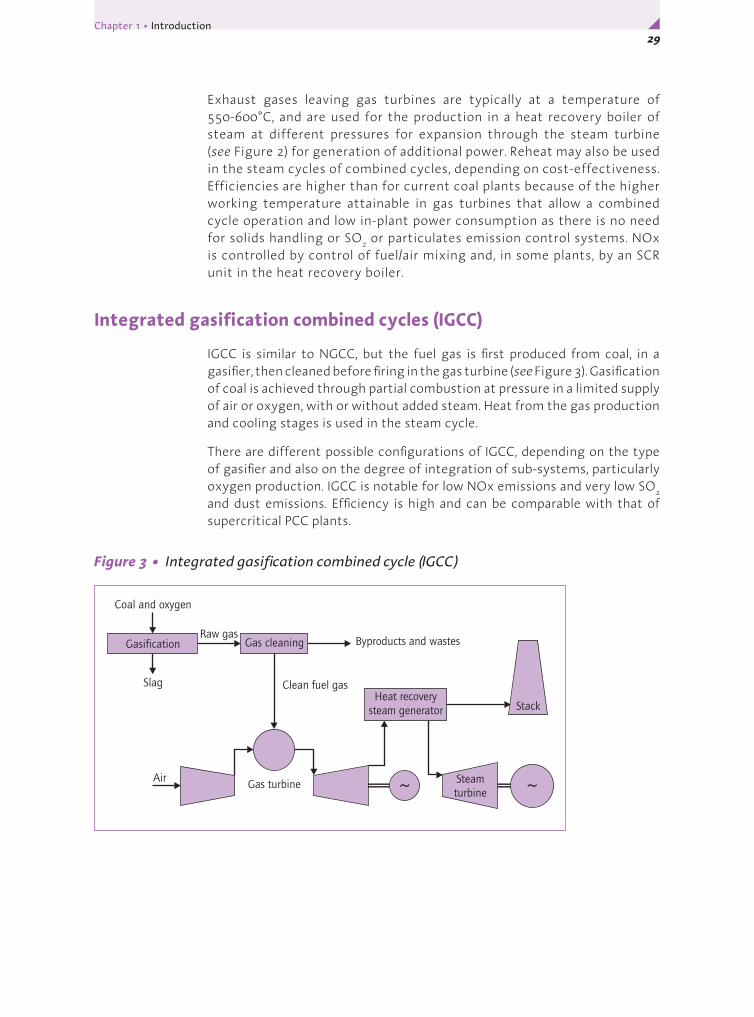
IGCC is similar to NGCC, but the fuel gas is first produced from coal, in a gasifier, then cleaned before firing in the gas turbine (see Figure 3). Gasification of coal is achieved through partial combustion at pressure in a limited supply of air or oxygen, with or without added steam. Heat from the gas production and cooling stages is used in the steam cycle.
There are different possible configurations of IGCC, depending on the type of gasifier and also on the degree of integration of sub-systems, particularly oxygen production. IGCC is notable for low NOx emissions and very low SO2 and dust emissions. Efficiency is high and can be comparable with that of supercritical PCC plants.
Figure 3 • Integrated gasification combined cycle (IGCC)
Gasification
Coal and oxygen
Raw gas
Clean fuel gas
Gas turbine
Heat recoverysteam generator Stack
Byproducts and wastes
Slag
Air
Gas cleaning
Steamturbine

FOSSIL FUEL-FIRED POWER GENERATION 30x
WAYS IN WHICH EFFICIENCY CAN BE EXPRESSED
The electrical efficiency of a power plant is the proportion of the fuel input energy that emerges as electric power, conventionally expressed as a percentage value. Another widely used measure is the heat rate, which is the fuel input energy divided by the electrical output energy, but this will only be used occasionally in this report. Although the concept of efficiency appears simple, there are many different ways of defining efficiency that result in differing numerical values. The consequence is that it is easy to arrive unintentionally at misleading comparisons of plants. The policy in compiling this report has been to seek clarification wherever there have been potential uncertainties in data being supplied and, when comparing, attempt as far as possible to bring them to a common basis.
The chemical energy available per unit mass of fuel may be quantified using either the higher heating value (HHV) – also known as the gross calorific value – or the lower heating value (LHV) – also known as the net calorific value. The HHV is the released heat measured at constant volume using a bomb calorimeter after all the products from combustion have been cooled to the initial temperature of the fuel and oxygen of 25°C. It includes the heat released when the water vapour in the product gas condenses into water (latent heat). In contrast, the LHV is the calculated heat obtained after the products of combustion have been cooled down assuming no condensation, so it does not include the latent heat. It is obtained from the higher heating value, basically by subtracting the calculated heat of vaporisation of the water in the combustion products. The use of LHV originally arose to reflect the situation in power plants, which in general do not cool the flue gas sufficiently to recover the latent heat because wet flue gas can cause corrosion from condensation of sulphuric acid formed from sulphur trioxide (SO3) in the gases. Temperatures are normally kept above the acid dew point, which is the temperature at which this would occur (an example of an exception is Niederaussem K, where the temperature within the flue gas cooler may fall low enough for partial condensation). An added complication is that the calculation of LHV frequently, but not invariably, includes subtracting the latent heat in the water vapour produced by evaporation of the moisture originally present in the coal, rather than just the latent heat of the water vapour formed from combustion of the coal hydrogen. This is the method described in the ISO standard*. There are other small differences in heating values depending on whether they refer to constant volume or constant pressure, but these effects tend to be minor for coals.
A plant efficiency value calculated from the fuel mass flow and LHV will be higher than the efficiency calculated using fuel HHV. For steam coals, the difference is typically around 3-4% of value. If the fuel moisture latent heat is subtracted in the LHV calculation, for black coals the HHV/LHV efficiencies ratio is increased slightly. For very moist fuels, such as lignites, the effect
* ISO 1928: 1995

31Chapter 1 • Introduction y
is to make the LHV efficiency on that basis 10-20% higher than that based on the HHV. Unfortunately, the basis of fuel LHV calculation is not usually explicitly stated, so care is needed in use of values, although it can generally be safely assumed that, in Europe, account is taken of the coal moisture, as in the ISO method. For this series of case studies, fuel calorific values and efficiencies are given on the basis of HHV as well as on the basis of LHV. The LHV bases varied, so where it is known that account was taken of coal moisture, this is stated in text. In other cases, the coal moisture latent heat is believed to be not subtracted.
A quoted efficiency may be the design value for the unit, which will be as calculated by the supplier, on the basis of a specified fuel or specified fuel property range, at maximum continuous rating. This will generally equate closely to the performance test value, determined from a run on the new unit over a carefully controlled period using the design fuel after the plant has stabilised at its nominal full output (known as maximum continuous rating).
The efficiency may be stated on either a net (sent out) value or a gross (generated) value. The sent out value will be lower, as it will allow for deduction of the power consumed by the plant itself by equipment such as crushers, fans, pumps, environmental control equipment, etc., and also allow for transformer losses.
Also cited can be the operating efficiency of a plant. This may typically be an average value over a whole year. Because of several effects including partial load operation, two-shifting, fuel quality effects, prevailing condenser temperature, operation at off-design conditions, it can be lower than the design efficiency. Most of the plants in these studies were operating at a high capacity factor, and so the operating efficiencies were at or close to design.
A very simple source of lack of clarity that often occurs is when efficiency differences or changes are described. Whether they refer to percentage point differences or percentage of value differences needs to be carefully stated. This is one advantage of using heat rates, as they are not normally expressed as percentages.
Summarising, it is important to be clear what bases are being used when efficiency data are given. In this report, the net efficiencies of the case studies plants are given on the basis of HHV as well as on the basis of LHV, and where it is known that account is taken of coal moisture, this is stated. An internationally agreed efficiency basis to use in material that cites efficiencies, together with a clear statement of what basis is being used, would be very valuable.
REPORT STRUCTURE
The remainder of this report is structured as follows. Chapter 2 introduces the reader to the main methods available for achieving high efficiency. Chapter 3 contains the case studies, including the NGCC plant and IGCC review.
FOSSIL FUEL-FIRED POWER GENERATION 32x
Chapter 4 draws general conclusions from the case studies, with a perspective on the technical and economic factors that guide choices between technologies. The nature and purpose of this series of studies meant that descriptions concentrate on the process facilities, so there is necessarily less discussion of other equipment. There was also little room in this particular study to review some other areas in which there have been significant advances, such as computer control systems. Acknowledgements and sources of information are listed after each case study. Appendix A at the end of the report shows a blank data enquiry questionnaire.
Background sources
ISO 1928: 1995 Solid mineral fuels - Determination of gross calorific value by the bomb calorimetric method, and calculation of net calorific value. International Organisation for Standardisation, Geneva, Switzerland (1995)
33Chapter 2 • Designing for High Efficiency y
Chapter 2 • DESIGNING FOR HIGH EFFICIENCY
The short outline in this chapter is not intended to be comprehensive, but to provide background to some general means available. An efficient plant is a plant that rejects less of the input energy of the fuel to the surroundings (i.e. to air and water). The first part of the power generation process in a combustion-based power plant is burning the coal and capturing the heat produced. Large state-of-the-art PCC boilers have efficiencies (HHV basis) around 90%. Combustion is generally 99-99.5% complete so that normally very little energy loss arises through unburnt fuel. This is achieved through fine grinding of the coal, optimum burner design, and careful control of the coal and air supplies.
Losses in heat capture may occur partly through radiation and air leakage past the boiler across the air heater, but mainly as heat remaining in the flue gases. Where very moist coals such as lignite are burnt, a major decrease in boiler efficiency will occur because of the high temperature heat used to dry the coal. Methods for pre-drying such coals using low grade heat with latent heat recovery are in development and, when implemented, these should raise efficiency by up to four percentage points.
In the other main part of the power production process, the high pressure superheated steam produced by the boiler is sent on to the turbine to create rotational energy to drive the generator. The design of turbine blades has improved considerably over the last 10 years through computer aided design and optimisation of blade profiles. However, the main steam temperature and pressure remain the most significant determining factors for the turbine efficiency. They are therefore among the first parameters to be decided upon in designing a boiler/turbine generating unit. The most efficient PCC plants operate at supercritical conditions. The steam parameters achievable depend on the materials that are selected for the boiler and turbine and pipework connecting them. Repeat reheating of the steam can also be used for higher efficiency in certain circumstances.
Current alloys allow high pressure main steam temperatures of 600°C and reheat steam temperatures somewhat higher to be used. Some plants now under construction will use 620°C for the reheat steam. Temperatures did reach around 600°C and higher in a few early supercritical boilers constructed around 1960, but these used less sophisticated materials and suffered from availability difficulties and lack of flexibility. Consequently, supercritical plants introduced between the 1960s and 1980s used lower temperatures. The materials available to manufacturers now have not only allowed a return to the higher steam temperatures, but also enabled sliding pressures to be used to achieve operational flexibility with less loss of efficiency. Longer term developments foresee much higher steam conditions, for which R & D activities on use of nickel superalloys are in progress for plant efficiencies of over 50% net on a lower heating value basis.
FOSSIL FUEL-FIRED POWER GENERATION 34x
The conventional method of water addition to the superheated and reheated steam for temperature control (attemperation) can have a significant negative impact on cycle efficiency because it diverts some of the pressurised feedwater away from much of the boiler heat absorption surfaces, especially when reheat steam attemperation is used. Alternative or additional methods, involving adjusting heat pick-up by tilting burners downwards, use of flue gas recirculation, biasing flue gas flows through parallel boiler convection passes, or very close control of air-fuel ratio may therefore be provided.
Increasing the boiler feedwater inlet temperature raises cycle efficiency. Supercritical plants can have final feedwater temperatures of up to 300°C. Feedwater heating is achieved by using steam extracted from the turbine at appropriate points to supply indirect heat exchangers and a direct contact heater that also acts as the water deaerator. The greater the number of feedwater heating stages, the greater the efficiency benefit, but cost increases also. Ten stages of feedwater heating have been used in some ultra-supercritical plants.
About half of the input energy to the steam cycle remains in the wet steam as it emerges from the last stages of the turbine. This energy leaves the plant via the condenser’s cooling water or cooling air. One way to minimise the relative size of this loss is by using high steam parameters, but the steam should also be expanded as much as possible, so that it transfers as much as possible of its energy to the rotor. While there are cost considerations, the main constraint is the geographical area in which a plant is to be situated, because a colder cooling sink improves condenser performance and hence allows a lower turbine exit pressure.
The other key way to use the low grade heat in the steam is in a district heating scheme in a combined heat and power (CHP) configuration, which can raise overall heat plus power efficiency to as high as 90%. Unfortunately, there are limits to the extent of practical application of CHP with district heating because appropriately large heat demands are rarely available to large power stations.
In many OECD countries, where utilities have been deregulated, flexibility to generate efficiently during periods of rapid load change has become more frequently specified, even for large units. Supercritical boilers, being once-through devices, are well-suited to rapid turndown without undue decrease in efficiency: they use variable pressure operation to reduce the need for turbine inlet valve throttling.
A generating station’s own power demand is an important part of the way output is lost. Most equipment areas on a power generation plant consume some power. A modern coal-fired unit with an electrically driven main boiler feed pump has a total auxiliary power demand of around 6-8% of gross generation. When the main feed pump (a large energy user) is driven by a dedicated turbine, auxiliary power demand is considerably reduced, but gross generation is also reduced since steam is taken from the main turbine to drive the boiler feed pump turbine. Power demand for fuel handling can increase considerably where coals are difficult to grind or have very high ash contents.

35Chapter 2 • Designing for High Efficiency y
Combined cycles are another route to high efficiency, because they allow a high temperature gas turbine to be combined with a low temperature of final heat rejection from the steam turbine. The highest gas turbine inlet temperatures are currently approaching 1400°C. There are other means of obtaining high gas turbine efficiencies, such as using reheat or cooling the air at inlet or between stages of compression.
This report also discusses emissions performance of case study plants. It should be noted that increasing the efficiency of a plant will reduce in proportion all emissions to air and other waste products. This is because less input fuel is needed to generate each unit of electricity.


37
Chapter 3 • CASE STUDIES AND IGCC TECHNOLOGY REVIEW
The following chapter consists of the individual case studies and a short review of coal-fired integrated gasification combined cycles. For convenience, Table 1 summarises main features of the eight coal-fired plants and the bases for the selection of each for study.
Table 1 • Main features of the eight coal-fired case study plants and bases for selection for study
PlantEurope – Denmark Nordjyllandsværket
3
Europe – Germany Niederaussem
K
North America – Canada
Genesee 3
Asia – Japan Isogo
New Unit 1
Siting coastal inland inland coastal
Coal international lignite sub-bituminous international
MWe net 384 965 450 568
Boiler geometry
tower tower 2-pass tower
Main suppliers: boiler; turbine
FLS miljo/BWE, Aalborg Industries, Volund Energy Systems; GEC Alsthom (now Alstom)
EVT (today Alstom), Babcock and Steinmüller (today HPE); Siemens
Babcock-Hitachi; Hitachi
IHI; Fuji Electric (Siemens)
Ultra-super-, super- or sub-crit
USC USC S/C USC
Steam conditions MPa/°C/°C (/°C)
29/582/580/ 580
27/580/600 25/570/570 25/600/610
Why selected
Most efficient coal plant; double-reheat; very low emissions
Lignite; top efficiency lignite plant; lignite drier demonstration
Sub-bituminous coal; first sliding press S/C North America
Very high steam; very low emissions; activated coke regenerable FGD
USC: ultra-supercritical (steam temperatures of 580°C and above)S/C: supercritical
1 2 3 4
Chapter 3 • Case Studies and IGCC Technology Review y
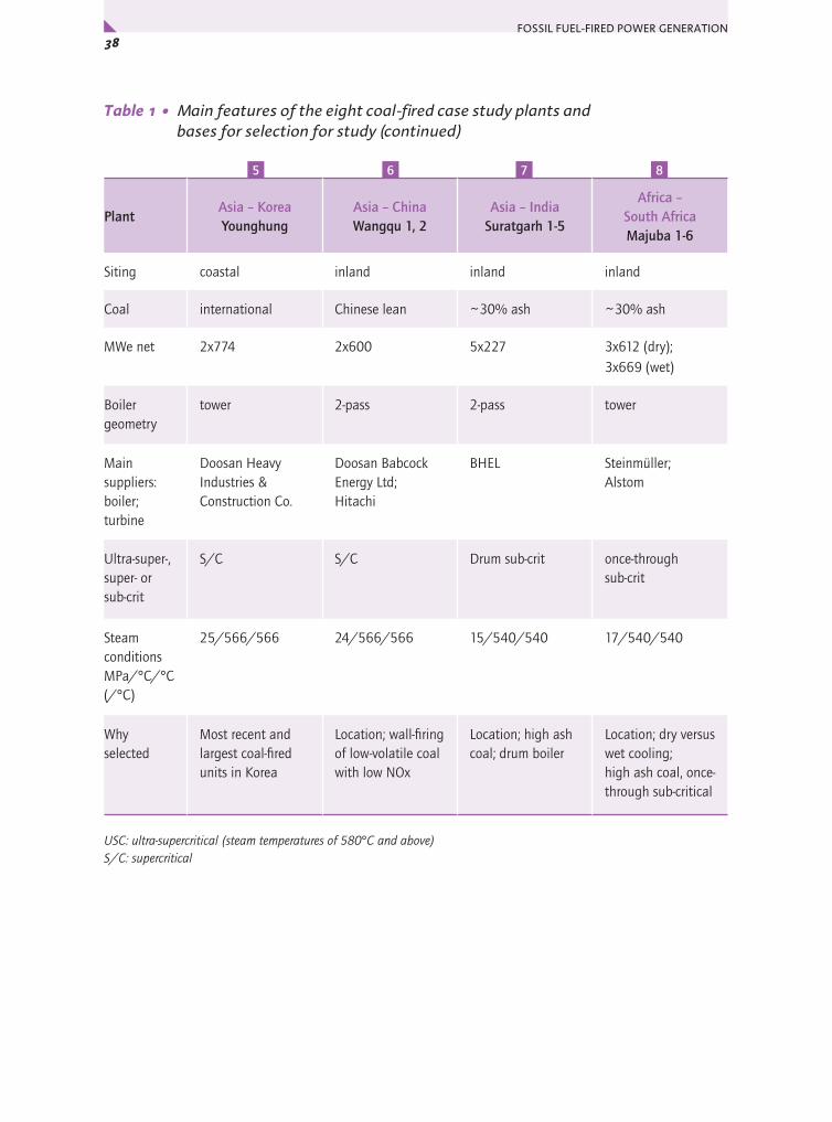
FOSSIL FUEL-FIRED POWER GENERATION 38x
Table 1 • Main features of the eight coal-fired case study plants and bases for selection for study (continued)
PlantAsia – Korea Younghung
Asia – China Wangqu 1, 2
Asia – India Suratgarh 1-5
Africa – South Africa Majuba 1-6
Siting coastal inland inland inland
Coal international Chinese lean ~30% ash ~30% ash
MWe net 2x774 2x600 5x227 3x612 (dry); 3x669 (wet)
Boiler geometry
tower 2-pass 2-pass tower
Main suppliers: boiler; turbine
Doosan Heavy Industries & Construction Co.
Doosan Babcock Energy Ltd; Hitachi
BHEL Steinmüller; Alstom
Ultra-super-, super- or sub-crit
S/C S/C Drum sub-crit once-through sub-crit
Steam conditions MPa/°C/°C (/°C)
25/566/566 24/566/566 15/540/540 17/540/540
Why selected
Most recent and largest coal-fired units in Korea
Location; wall-firing of low-volatile coal with low NOx
Location; high ash coal; drum boiler
Location; dry versus wet cooling; high ash coal, once-through sub-critical
USC: ultra-supercritical (steam temperatures of 580°C and above)S/C: supercritical
5 6 7 8

39Chapter 3 • Case Studies – Coal-Fired Plant 1: Northern Europe y
COAL-FIRED PLANT NORTHERN EUROPE
Sea water cooled ultra-supercritical plant – Nordjyllandsværket 3, Denmark
Introduction
Some of the most efficient coal-fired power plants in the world are located in Denmark, where new generation pulverised coal supercritical plants with sliding pressure were introduced in the 1990s as a result of initiatives by Elsam to move to much higher efficiency plants by working with the major suppliers to develop designs. Coal accounts for 50% of electricity production in Denmark.
The Nordjylland power station (Nordjyllandsværket) is a sea water cooled power station fuelled by imported international bituminous coal. Coals sources vary but currently are Poland, Russia and South Africa. The power station is situated on the north bank of the Limfjord, about 10 kilometres North East of the Northern Danish town of Aalborg. The short distance to an urban area with some 200,000 inhabitants offered the opportunity to establish a pipeline for hot water to an existing grid for district heating. Commissioned in 1998, the net electrical output of Unit 3 for no heating load is 384 MWe and gross electrical output is 411 MWe. At nominal heat output of 300 MJ/s (MWth), gross electrical output is 340 MWe.
Figure 4 • Nordjyllandsværket general viewC
ourt
esy
Vat
tenf
all
1
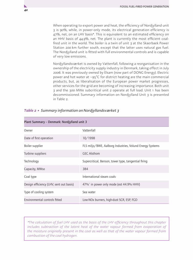
FOSSIL FUEL-FIRED POWER GENERATION 40x
When operating to export power and heat, the efficiency of Nordjylland unit 3 is 90%, while, in power-only mode, its electrical generation efficiency is 47%, net, on an LHV basis*. This is equivalent to an estimated efficiency on an HHV basis of 44.9%, net. The plant is currently the most efficient coal-fired unit in the world. The boiler is a twin of unit 3 at the Skaerbaek Power Station 200 km further south, except that the latter uses natural gas fuel. The Nordjylland unit is fitted with full environmental controls and is capable of very low emissions.
Nordjyllandsværket is owned by Vattenfall, following a reorganisation in the ownership of the electricity supply industry in Denmark, taking effect in July 2006. It was previously owned by Elsam (now part of DONG Energy). Electric power and hot water at ~95°C for district heating are the main commercial products, but, as liberalisation of the European power market progresses, other services for the grid are becoming of increasing importance. Both unit 3 and the 300 MWe subcritical unit 2 operate at full load. Unit 1 has been decommissioned. Summary information on Nordjylland Unit 3 is presented in Table 2.
Table 2 • Summary information on Nordjyllandsværket 3
Plant Summary – Denmark: Nordjylland unit 3
Owner Vattenfall
Date of first operation 10/1998
Boiler supplier FLS miljo/BWE, Aalborg Industries, Volund Energy Systems
Turbine suppliers GEC Alsthom
Technology Supercritical, Benson, tower type, tangential firing
Capacity, MWso 384
Coal type International steam coals
Design efficiency (LHV, sent out basis) 47%* in power only mode (est 44.9% HHV)
Type of cooling system Sea water
Environmental controls fitted Low-NOx burners, high-dust SCR, ESP, FGD
*The calculation of fuel LHV used as the basis of the LHV efficiency throughout this chapter includes subtraction of the latent heat of the water vapour formed from evaporation of the moisture originally present in the coal as well as that of the water vapour formed from combustion of the coal hydrogen.

41Chapter 3 • Case Studies – Coal-Fired Plant 1: Northern Europe y
Main challenges met in designing the plant
The availability of cold sea water at around 10°C was a major factor influencing the design. It enabled a low condensate temperature to be achieved and hence a very low turbine exhaust pressure of 2.3 kPa. This gives a high volumetric flow in the last stage of the steam turbine, raising output and efficiency. However, a major technical challenge in designing such plant in Northern Europe (and similar cold water areas around the world, e.g. the Great Lakes) is the resultant high wetness of the steam in the last stages of the low pressure turbine. During wintertime the wetness might exceed 15% in conventional single reheat cycles, causing severe erosion by water droplets of the turbine blades in this area. In order to tackle this, further heat needs to be added to the steam by a second reheat step, so that, when the steam reaches the last stages of the low pressure turbine, it contains less of the water as liquid, and more as saturated steam. At Nordjylland 3, the double reheat cycle adopted to achieve this has proved to be very effective in solving the wetness problem. Wetness of the exhaust steam is reduced to around of 8% and operational experience shows that steam wetness this small does not cause erosion problems.
The second challenge at Nordjylland 3 was associated with the need to use materials available at that time for headers and pipework to handle main steam and reheat steam temperatures of 580°C, which was 20°C above the normal maximum at that time. Detailed boiler design studies enabled this to be met by using finely grained austenitic steel HTP 347 FG for the final superheater and the then new martensitic high temperature steel P91 for headers and main and reheat steam pipework. Part of the solution was the double reheat cycle, which resulted in around 10% reduction in main steam flow, and so kept the size of the pressure parts smaller.
The third major challenge was to keep the temperature of the furnace wall tube material 13 CrMo44 (T11) within design limits during the whole life of the plant. The temperature of the water/steam side of the furnace wall tubing is higher in these ultra-supercritical cycles and this can lead to a tendency for iron to deposit on the inside of the furnace tubes. This was solved by using a suitable rate of flue gas re-circulation to control temperatures and advanced water treatment to ensure stable oxide layers. In addition to good design, steam blowing to remove any deposits in superheater and reheater tubing is carried out when starting the plant.
Overall configuration
The overall configuration is similar to that in Figure 1. The coal is burned in a tower boiler that was supplied by a consortium of FLS miljo/BWE, Aalborg Industries and Volund Energy Systems. NOx emissions are controlled by a combination of combustion measures and a selective catalytic reduction unit. Electrostatic precipitators collect fly ash, and a wet flue gas desulphurisation unit desulphurises the emerging flue gas, which is then sent to a 200 m stack.

FOSSIL FUEL-FIRED POWER GENERATION 42x
The boiler converts water to superheated supercritical steam in a single pass. The steam is expanded in an ultra-supercritical turbine supplied by GEC Alsthom, reheated in the boiler, further expanded, reheated a second time, expanded once more, then finally condensed and returned as water to the boiler. The condenser is cooled with sea water. Some steam is taken from the turbine to serve condensing heat exchangers to heat the district heating water. Steam conditions are 29 MPa/582°C/580°C/580°C. This selection of main steam parameters was based on a balance of the concerns to minimise fuel use, cost and emissions while keeping risk as low as possible for a state-of-the-art plant.
Table 3 • Selected performance-related information on Nordjyllandsværket 3
Operating efficiency (LHV, sent out basis) 47% for no district heating load (est 44.9% HHV basis) – not an annual average
Fuel calorific value (a.r.), MJ/kg LHV and HHV 25.2 (26.4 HHV)
Fuel ash content (a.r.), % 12.6
Fuel moisture content (a.r.), % 9.7
Fuel sulphur content (a.r.), % 0.5
Gross power output, MWe, at MCR 411 in absence of district heating load
Net power output, MWso, at MCR 384 in absence of district heating load
Auxiliary power consumption, MWe at MCR 27
Main boiler feed pump drive (motor or turbine) Variable speed motor
Steam conditions 29 MPa/582°C/580°C/580°C at boiler
Feedwater heating stages 8 LP + deaerator + 3 HP
Final feedwater temperature, °C 300
Type of cooling system, water temperature, °C Sea water, ~10°C at inlet
Condenser pressure, kPa 2.3
NOx abatement systems Low-NOx, air staging, high-dust SCR
NOx emissions, 6% O2, dry 146 mg/m3
Desulphurisation system Wet FGD
SO2 emissions, 6% O2, dry 13 mg/m3
Particulates removal system ESP
Particulates emissions, 6% O2, dry 18 mg/m3
Specific capital cost, USD/kWso 1500 USD/kWso (2006) for a new 800 MWe plant excluding owner’s costs and IDC

43Chapter 3 • Case Studies – Coal-Fired Plant 1: Northern Europe y
In addition to the advanced steam conditions and double reheat, auxiliary power has been kept low (6.5%, despite use of electrical drives for the main boiler feed pumps), keeping efficiency high. Low auxiliary power has been achieved through a number of measures.
Plant description
Coal reception, handling and preparation
Coal landed at the immediately adjacent wharf is transported by conveyors from the storage area to four bunkers that feed four vertical spindle mills. The coals from different sources are stacked in separate parts of the storage area so that they can be selectively reclaimed or blended. A predictive software system aids selection of the daily optimal mix for economic, efficient and low emissions operation, taking into account factors such as ash alkali and chloride content, sulphur content, calorific value, and so on. A typical coal composition as fired was shown table 3. At nominal rating, three of the MPS vertical spindle roller mills are used, with one spare, but output can be temporarily raised by 10% by shutting off the HP bleed heaters and using all four mills.
Boiler combustion system
The ultra-supercritical boiler is tangentially fired with 16 low-NOx burners, each with staged introduction of four air flows. The burners are arranged at four levels at the boiler corners. There is an overburner air nozzle above each burner and also an over-fire air (OFA) system above the top level burners. These systems together give effective primary NOx control and high burnout.
Boiler heat transfer surfaces
All the high temperature heat extraction surfaces (see Figure 5) are located above the furnace, apart from the evaporator tubing, which, as in all PCC boilers, is welded to form a membrane wall to the boiler. The evaporator is spiral wound. For use during start-up, there is a system for recirculation of separated water after it leaves the evaporator but this is not used during normal once-through operation. The boiler-turbine unit is designed for sliding pressure operation to meet load variations.
The economiser is located at the top of the tower boiler, above the reheater sections, which are themselves located above the superheater surfaces. The final superheater sections are in parallel flow and kept small so that the temperatures at the outlet are fairly close to the temperature after final attemperation and so easier to keep in balance. Superheated steam temperature is controlled by attemperation between the stages, while reheat temperature is controlled normally by flue gas recirculation so the reheat steam spray attemperators are not normally used.
The materials used were discussed in the previous section – Main challenges met in designing the plant.

FOSSIL FUEL-FIRED POWER GENERATION 44x
Figure 5 • The boiler and air supply arrangements at Nordjylland 3
Draught system
The boiler operates conventionally, i.e. slightly sub-atmospherically under balanced draught (see Figure 5 above). Two forced draught (FD) air fans take suction from inside at the top of the boiler house. The single primary air fan takes suction from the FD fans outlets.
The primary and secondary combustion air flows are heated using a rotary Ljungstrom regenerative airheater that extracts heat from the combustion gases leaving the economiser at the top of the boiler. A steam/air preheater is also provided for the combustion air for use when required. The heated primary air, after tempering, dries and conveys the pulverised coal from the mills to the burners on the boiler. The heated secondary air from the airheater is admitted to the furnace above each burner row (over-burner air) and, higher, as over-fire air to ensure efficient burnout and low NOx emissions.
Flue gas is drawn through the boiler by induced draught fans after the electrostatic precipitators. Before it reaches the ID fans, about 10% of the flue gas after the ESPs is recirculated by a fan to the boiler via the air heater to provide reheat steam control and to keep metal temperatures at satisfactory levels. The rotary airheater, consequently, is unusual in having four sectors.
ID fans
Steam/air preheater
FD fans
4
Primary air
4 Mills4 burners
Combustion air intake
ESPsRecirculation fan
8
8
1616
ECORH1.1RH2.1RH1.1
SH1/RH2.2SH2/RH1.2
SH1Screen
FGR
OFA
Coal/primary air
Tertiary airSecondary air
OBA
4x4=16Burners
4
Primary airfans
16FGD
Rotary air heater
DeNOx
Cou
rtes
y V
atte
nfal
l

45Chapter 3 • Case Studies – Coal-Fired Plant 1: Northern Europe y
Flue gas recirculation (FGR) is increased at part load. The air heater flue gas outlet temperature is 115°C.
Emissions control equipment
NOx control
A combination of combustion measures and selective catalytic reduction (SCR) with ammonia addition is used for NOx control. Low-NOx axial swirl burners mounted in the corners of the boiler fire tangentially into the furnace. Individual over-burner air and over-fire air are also used for air staging. These result in NOx levels of only 400 mg/m3 in the top of the boiler before the SCR.
The high dust SCR, which is integrated into the boiler flue gas exit, just ahead of the Ljungstrom airheater, is then used to reduce NOx levels to no more than 150 mg/m3. The economically most favourable combination of combustion air control and ammonia injection to the SCR is used to achieve the required concentration each day at present. It is clear that a much lower release of NOx could be achieved on this plant if required.
Particulates and ash utilisation
The electrostatic precipitators are located after the airheater. Over 90% of the coal ash appears as fly ash. The electrostatic precipitators take the concentration of particulates to below 50mg/m3 ahead of the FGD. After the FGD, the total particulates concentration in the stack gas is typically less than 20mg/m3, including aerosols.
Virtually all ash is sold for utilisation, mainly for cement production and use as aggregate for the construction industry. Ashes of different quality (carbon content) are stored in separate silos. There is no need for settlement ponds, and only a very small quantity of ash has had to be retained in a small area because it fell outside specification for sale when a particular coal was fired.
Flue gas desulphurisation
A wet scrubbing FGD system designed by MHI that produces byproduct gypsum is used to reduce SO2 emissions from the flue gas exiting the precipitators. This uses as reagent limestone and chalk supplied by the cement industry that is free of cost in exchange for the free supply of product gypsum from the power station to the cement factory.
SO2 emissions are extremely low – around 15mg/m3 at 6% oxygen, dry. In fact, at part load, the operating staff switch off one of the four recirculating pumps in the FGD so that the SO2 emissions can be measurable and to save power. The pH of the slurry in the FGD is critical to gypsum quality so an organic acid is used as a buffer. Typically 98.8% SO2 removal is achieved on a 0.5% sulphur content coal. The originally installed inlet gas/cleaned gas heat exchange across the FGD is not required as spray water can be added instead before the FGD inlet to set the temperature right for the absorber (55°C). Stack gases go off to the stack at that temperature and there are no reported difficulties with plume dispersion.
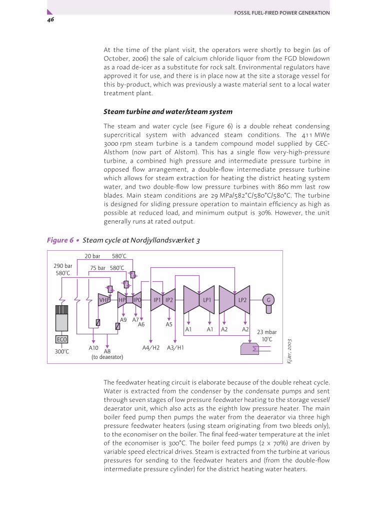
FOSSIL FUEL-FIRED POWER GENERATION 46x
At the time of the plant visit, the operators were shortly to begin (as of October, 2006) the sale of calcium chloride liquor from the FGD blowdown as a road de-icer as a substitute for rock salt. Environmental regulators have approved it for use, and there is in place now at the site a storage vessel for this by-product, which was previously a waste material sent to a local water treatment plant.
Steam turbine and water/steam system
The steam and water cycle (see Figure 6) is a double reheat condensing supercritical system with advanced steam conditions. The 411 MWe 3000 rpm steam turbine is a tandem compound model supplied by GEC-Alsthom (now part of Alstom). This has a single flow very-high-pressure turbine, a combined high pressure and intermediate pressure turbine in opposed flow arrangement, a double-flow intermediate pressure turbine which allows for steam extraction for heating the district heating system water, and two double-flow low pressure turbines with 860 mm last row blades. Main steam conditions are 29 MPa/582°C/580°C/580°C. The turbine is designed for sliding pressure operation to maintain efficiency as high as possible at reduced load, and minimum output is 30%. However, the unit generally runs at rated output.
Figure 6 • Steam cycle at Nordjyllandsværket 3
The feedwater heating circuit is elaborate because of the double reheat cycle. Water is extracted from the condenser by the condensate pumps and sent through seven stages of low pressure feedwater heating to the storage vessel/deaerator unit, which also acts as the eighth low pressure heater. The main boiler feed pump then pumps the water from the deaerator via three high pressure feedwater heaters (using steam originating from two bleeds only), to the economiser on the boiler. The final feed-water temperature at the inlet of the economiser is 300°C. The boiler feed pumps (2 x 70%) are driven by variable speed electrical drives. Steam is extracted from the turbine at various pressures for sending to the feedwater heaters and (from the double-flow intermediate pressure cylinder) for the district heating water heaters.
ECO
300 Co
290 bar580 Co
23 mbar10 Co
75 bar 580 Co20 bar 580 Co
A10
A9
A8(to deaerator)
A7A6
A1
A4/H2 A3/H1
A5A1 A2 A2
LP1 LP2IP2IP1IP0HPVHP G
Kjæ
r, 20
03

47Chapter 3 • Case Studies – Coal-Fired Plant 1: Northern Europe y
Each low pressure turbine has a water cooled condenser mounted beneath it where the wet steam emerging from the turbine is fully condensed to water. The condenser pressure is 2.3 kPa. Cooling water for the condensers comes from the Limfjord.
Plant control system
The sophisticated plant control system includes plant wide system configuration, documentation and diagnostics, trending and analysis. It uses both recently installed PC-based consoles and the original control consoles in tandem and either can be used.
Economics
No cost information was available from the current plant operators. According to DONG Energy, the plant contracting strategy was owner design with multi-contract procurement. This achieved a low investment cost and is still the preferred system at DONG Energy. Construction time was 48 months. The unit was built within the existing power plant boundary. Information obtained from Siemens by DONG Energy on the current cost (late 2006) of an 800 MWe ultrasupercritical plant indicates that it would be around 1100-1200 €/kWso (corresponding to a mid-range value of around 1500 USD/kWso), excluding owner’s costs and interest during construction.
DONG Energy say that no increases in operating and maintenance costs were seen during Elsam’s ownership. Vattenfall say that there are 22 operating staff.
The plant is generally run at full output but, if for some reason a very low loading is called for (below 25%), a light fuel oil is used. Unlike HFO, this has little vanadium, allowing the high steam conditions to be maintained. The unit is not usually operated at mid-loading.
Commentary
This unit is still the most efficient coal-fired power plant in the world, yet it was commissioned nine years ago. This achievement was a result of initiatives by the utility to move to much higher efficiency plants of high flexibility by working with the major suppliers to develop designs that are practical and economic for ultra-supercritical steam conditions. It is not possible to give an average long-term efficiency in absence of a district heat load, but operating efficiency is said to be at design value.
High performance was realised despite the need for a small blade height in the first stages of the HP turbine due to the relatively small plant size and very high main steam pressure. An impulse-type turbine is used at Nordjylland 3, but reaction types are more commonly supplied now for very high steam conditions as longer blade lengths are used, making it easier to achieve predicted performance.
FOSSIL FUEL-FIRED POWER GENERATION 48x
Double reheat cycles are very effective in reducing or eliminating erosion problems of the final running blades of low pressure turbines. Double-reheat has been economically worthwhile, especially as coal prices have risen and a price has developed for CO2.
Many new materials have been introduced during recent years and this is a trend set to continue. It is important that plant designers continue to have the best possible insight into the behaviour and nature of new materials being introduced into boilers, steam lines and turbines. Techniques such as flue gas recirculation or modified operating procedures can be valuable in reducing the stress on materials.
Auxiliary power has been kept very low at Nordjylland 3 (only 6.5%, despite the use of electrically driven main feed pumps) by several measures:
y saving fan power through obtaining a reduced pressure drop when replacing the SCR catalyst bed (new supplier);
y using only the minimum necessary number of ESP fields, depending on the firing rate and the ash resistivity of the coals being fired;
y an on-going programme to save electricity in buildings.
This unit’s spectacular performance with regard to efficiency is matched by its environmental performance. Emissions to air are well below those required by the regulators. It is notable that there are, to all intents and purposes, no waste products from the plant. Thus, virtually all ash is sold and gypsum exchanged for FGD reagent.
The lengths to which the operators are prepared to go in minimising the plant’s environmental impact is shown in their most recent measure. They have secured a use for what until now was the only significant stream of waste material from the plant. Calcium chloride from the FGD, until now discharged in solution to a local water treatment plant, is to be sold as a road de-icer as a substitute for rock salt. It has been approved by the environmental regulators for use, and will therefore avoid the need for the exploitation of rock salt for this purpose. Calcium chloride is a normal waste stream from limestone/gypsum FGD plants and this sets an excellent example of what can be done through creative approaches to established procedures.
Future plans
Danish plant owners continue to be committed to furthering development of power generation steam cycles of higher efficiency. Installation of natural gas-fired projects during the 1990s led to a gap in the ordering of new coal-fired units, and the Danish Government stopped the construction of an ultra-supercritical coal-fired plant at Avedøre with a planned net LHV efficiency of 48.3%.
DONG Energy has recently devised and patented a modified double reheat high temperature steam cycle incorporating an additional small high speed turbine generator supplied with its steam by the very high pressure turbine

49Chapter 3 • Case Studies – Coal-Fired Plant 1: Northern Europe y
outlet. Bleed steam flows from this turbine would be used in place of most of the high temperature bleeds from the main turbine for high pressure feedwater heating. The system would be even more efficient than the basic double reheat cycle, and lower cost steels could also be used for the steam bleed tubework, which would be cooler. Output from the additional turbine could provide the mechanical drive for the boiler feed pump. The system is calculated to offer a 3% improvement in heat rate over the existing double reheat cycle (over 1 percentage point), without the need to move to higher main steam temperatures.
Elsam has been one of the leading players in the AD700 demonstration project to develop 700°C boiler and turbine components in Europe. DONG Energy also has extensive involvement in the related COMTES700 demonstration in Germany.
Acknowledgements
Soreen Peen, Vattenfall, Nordjyllandsværket 3 and Svend Molbach, Vattenfall, Nordjyllandsværket 3 for hosting the plant visit and providing data.
Sven Kjaer, DONG Energy, for valuable discussions and data and providing part of the text input to this section.
Background sources
Modern Power Systems Advanced technology for Nordjyllandsværket Unit 3. Modern Power Systems (May, 1998).
Noer M and Kjær S Development of ultra super critical PF power plants in Denmark, World Energy Council, 17th World Energy Congress, Houston (1998). Available from: http://www.worldenergy.org/wec-geis/publications/default/tech_papers/17th_congress/2_2_02.asp (1998) (accessed November 2006).
Kjær S Review of supercritical power plant technology. Presentation to Canadian CCT Roadmap meeting, Calgary, 20-21 (March, 2003) (accessed November 2006).
X-rates.com Euro to USD conversion in 2006. Available from: http://www.x-rates.com/d/USD/EUR/hist2006.html (accessed March 2007).
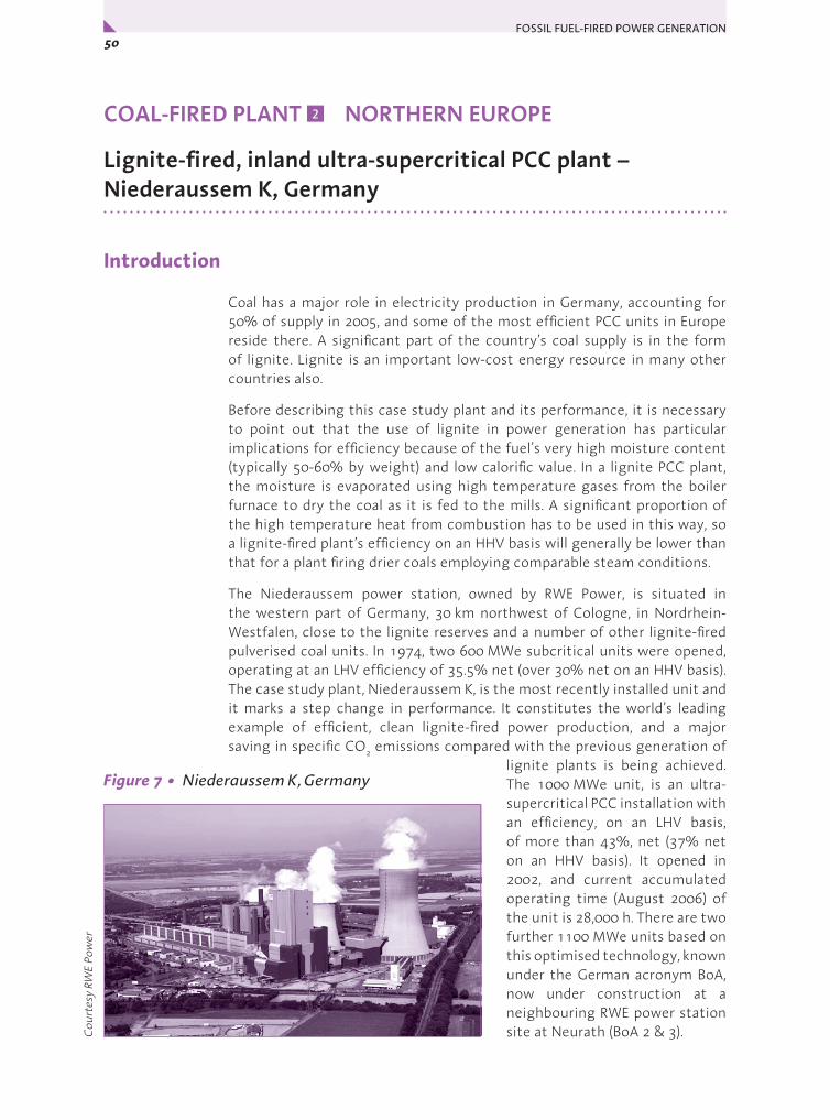
FOSSIL FUEL-FIRED POWER GENERATION 50x
COAL-FIRED PLANT NORTHERN EUROPE
Lignite-fired, inland ultra-supercritical PCC plant – Niederaussem K, Germany
Introduction
Coal has a major role in electricity production in Germany, accounting for 50% of supply in 2005, and some of the most efficient PCC units in Europe reside there. A significant part of the country’s coal supply is in the form of lignite. Lignite is an important low-cost energy resource in many other countries also.
Before describing this case study plant and its performance, it is necessary to point out that the use of lignite in power generation has particular implications for efficiency because of the fuel’s very high moisture content (typically 50-60% by weight) and low calorific value. In a lignite PCC plant, the moisture is evaporated using high temperature gases from the boiler furnace to dry the coal as it is fed to the mills. A significant proportion of the high temperature heat from combustion has to be used in this way, so a lignite-fired plant’s efficiency on an HHV basis will generally be lower than that for a plant firing drier coals employing comparable steam conditions.
The Niederaussem power station, owned by RWE Power, is situated in the western part of Germany, 30 km northwest of Cologne, in Nordrhein-Westfalen, close to the lignite reserves and a number of other lignite-fired pulverised coal units. In 1974, two 600 MWe subcritical units were opened, operating at an LHV efficiency of 35.5% net (over 30% net on an HHV basis). The case study plant, Niederaussem K, is the most recently installed unit and it marks a step change in performance. It constitutes the world’s leading example of efficient, clean lignite-fired power production, and a major saving in specific CO2 emissions compared with the previous generation of
lignite plants is being achieved. The 1000 MWe unit, is an ultra-supercritical PCC installation with an efficiency, on an LHV basis, of more than 43%, net (37% net on an HHV basis). It opened in 2002, and current accumulated operating time (August 2006) of the unit is 28,000 h. There are two further 1100 MWe units based on this optimised technology, known under the German acronym BoA, now under construction at a neighbouring RWE power station site at Neurath (BoA 2 & 3).
2
Cou
rtes
y RW
E Po
wer
Figure 7 • Niederaussem K, Germany

51Chapter 3 • Case Studies – Coal-Fired Plant 2: Northern Europe y
RWE produces the greatest single proportion of its power (41%) from lignite. It has three large opencast mines supplying their power plants in the Rhenish lignite-mining area: Hambach, Garzweiler and Inden. The eight currently operating older units at Niederaussem and Unit K use just two of the coals (Hambach and Garzweiler), blended to avoid problems associated with ash composition. Table 4 presents summary information on the Niederaussem K unit.
Table 4 • Summary information on Niederaussem K
Plant Summary – Germany: Niederaussem Unit K
Owner RWE Power
Date of first operation 2002
Boiler suppliers EVT (today Alstom), Babcock and Steinmüller (today HPE)
Turbine supplier Siemens
Technology Once-through supercritical, tower type
Capacity, MWso 965
Coal type Lignite
Design efficiency (LHV, sent out basis) 43.2% (37% HHV)
Type of cooling system natural draught cooling tower
Environmental controls fitted NOx control by combustion measures, dust by ESP, SO2 by limestone-gypsum FGD
Main challenges met in designing the plant
Niederaussem needed to have a very large boiler to burn the high (50-60%) moisture content lignite and produce sufficient steam for a nominal 1000 MWe unit. The huge once-through tower type boiler is 26 m square and 162 m high. The necessity to avoid slagging with the lignite fuel at such high steam temperatures also had to be taken into account in the design. Hambach coal has gradually increased in alkali content and so is of increased slagging propensity. It was also decided to have a start-up system that did not require an additional type of fuel (dried lignite is used), and it needed to have alternative ash handling systems to convey away the large quantities of ash in case one system should fail to maintain operation.
The high main steam parameters, selected as part of the route to high efficiency at the time of construction, were a challenge. The materials to be used (17% chromium) would be an improvement on the more familiar steels
FOSSIL FUEL-FIRED POWER GENERATION 52x
and enable thinner tube wall thicknesses to be used, but would be operating at the very edge of their capability. These materials were the most advanced that were then approved for use in pressure parts in Germany: although even more advanced steels were approved in some locations abroad, it would not be possible to use them at Niederaussem at first.
There was also a decision to use a low condenser pressure that necessitated a very efficient cooling tower design for this inland site. It was also decided to use an unconventional flue gas cooling circuit to further raise the efficiency.
The success of the manufacturers and of RWE in overcoming the potential difficulties is apparent in their experience with the plant.
Overall configuration
The pulverised fuel is burned in a large tower boiler supplied by a consortium of EVT (today: Alstom), Babcock and Steinmüller (today: Hitachi Power Europe, HPE), raising ultra-supercritical steam. NOx emissions from the boiler are low and there is no need for downstream flue gas NOx control equipment. Electrostatic precipitators collect fly ash, and a wet flue gas desulphurisation unit desulphurises the emerging flue gas before discharge, which here is within the cooling tower. As with all supercritical boiler plants, the boiler water is heated then converted totally to superheated supercritical steam in a single pass through the boiler. The steam is expanded in an ultra-supercritical turbine, reheated, further expanded, and finally condensed and returned as water to the boiler.
In addition to the advanced steam conditions, there are many features that have been designed into the plant to enable it to have a high efficiency. There is a large number of stages of feedwater heating with a complex water circuit to exploit part of a unique heat recovery system downstream of the main economiser. The latter is a novel by-pass economiser arrangement in parallel with the main airheaters. The other original feature in the flue gas heat capture arrangements is a flue gas cooler for final heat recovery to lower temperatures than is possible in conventional systems. This returns heat to the combustion air. Both of these systems are discussed later. The turbine outlet pressure has been made low, so the steam is expanded more than usual for an inland located power plant, by incorporating an advanced, unusually tall cooling tower. The plant’s own power demand was also minimised through design. Steam parameters at the turbine are 27.5 MPa/580°C/600°C.
A demonstration plant for drying part of the lignite fuel feed to enable higher efficiencies is being installed at the plant.

53Chapter 3 • Case Studies – Coal-Fired Plant 2: Northern Europe y
Table 5 • Selected performance-related information on Niederaussem K
Annual operating efficiency (LHV, sent out basis) 43.2% (37% HHV basis)
Fuel calorific value (a.r.), MJ/kg LHV and HHV 10.5 (12.24 HHV)
Fuel ash content (a.r.), % 6 (guarantee coal); design 2-12%
Fuel moisture content (a.r.), % 53,3 (guarantee coal); design 51-58
Fuel sulphur content (a.r.), % Typically 0.2 (Hambach)
Gross power output, MWe, at MCR 1012
Net power output, MWso, at MCR 965
Auxiliary power consumption, MWe at MCR 48
Main boiler feed pump drive (motor or turbine) Turbine
Steam conditions 27.5 MPa/580°C/600°C
Feedwater heating stages 6 LP + deaerator + 3 HP
Final feedwater temperature, °C 295
Type of cooling system, water temperature, °C Cooling tower, 14.7°C inlet
Condenser pressure, kPa 2.8 and 3.4
NOx abatement systems Tangential wall-firing, low-NOx combustors, overfire air
NOx emissions, 6% O2, dry max. 200 mg/m3
Desulphurisation system Wet FGD
SO2 emissions, 6% O2, dry < 200 mg/m3
Particulates removal system ESP
Particulates emissions, 6% O2, dry max. 50 mg/m3
Specific capital cost, USD/kWso ~1175 (2002) including IDC and owner’s costs
Plant description
Coal reception, handling and preparation
Lignite is brought in by rail to the stocking yard then transported by conveyor to the unit bunkers. Computer-aided stockpile management at the Hambach mine enables RWE to control the quality product to the power plants. On Niederaussem K, the milling equipment consists of eight beater mills, each with a 4 m diameter rotor weighing 36 t. The mills are also equipped with pre-crushers to make sure that deteriorating coal grindability (a known problem with the lignites used) does not lead to combustible losses. The unit operates at full load with six mills normally operating, one as spare and

FOSSIL FUEL-FIRED POWER GENERATION 54x
one under maintenance. The mills are supplied with combustion gases at approximately 1000°C recirculated from the furnace to dry and convey the pulverised lignite to the burners.
Boiler combustion system
The lignite-specific low-NOx burners are located on all walls of the boiler and are directed to give an imaginary circle to form a circulating fireball. This form of wall firing, arranged to give tangential introduction, is the conventional means used for lignites. The benefit of this burner arrangement is a good mixture of coal and combustion air, which leads to a high burnout efficiency. In addition, advanced burner designs and elaborate fuel and air staging ensure particularly good low-NOx performance here. The burners are arranged vertically with the main burners just above the evaporator hopper and reburners at a level somewhat higher. The preheated combustion air is introduced to the boiler at the level of the burners (primary and secondary combustion air) for reduction of NOx emissions with high burnout efficiency. Over-fire air is added at two elevated levels.
Excess air has been kept to a minimum (15%) to reduce fan power and flue gas loss. Fouling of heat transfer surfaces is prevented by low and even flue gas temperature at the exit of the combustion chamber. Start-up uses dried lignite in separate burners. The dry lignite is prepared at a plant near to the coal storage area.
Coal drying demonstration
Recycle of high temperature furnace gas to the beater mills is used to evaporate the large amount of moisture in the coal. As stated in Introduction, only some of this heat is capable of being recovered, so the efficiency of all plants using such high moisture fuels is lower than for comparable plants firing drier fuels.
BoA concept
Energetic disadvantages: drying at very high exergy levelno use made of vapour energy
Raw lignite
BoA concept with predried lignite
Boiler
Flue gas+ vapour1 000 C
hot flue gaso
Dry lignite+ flue gas+ vapour
Integratedmilldrying
Energetic improvement: drying at low exergy level (low pressure vapour)use made of vapour energy
Boiler
Flue gas
Dry lignite
Predrying(WTA)
Condensate
Heating steam fromturbine bleedingVapour for boilerfeedwater heating
Fluidized-bed drier
Raw lignite
Cou
rtes
y RW
E Po
wer
Figure 8 • WTA lignite drying in comparison with conventional system

55Chapter 3 • Case Studies – Coal-Fired Plant 2: Northern Europe y
Niederaussem K achieves a much better efficiency than previous lignite units because of the efficiency maximising measures of the BoA system. However, lignite drying process designs that can reduce the energy penalty are clearly desirable, and RWE are about to demonstrate a fluidised bed lignite pre-drying system (the WTA process) on this unit.
Figure 8 shows the principle, in comparison with the conventional system. The plant, to treat 25% of Unit K’s input fuel, is shown in Figure 9. The system has been under development for over ten years. The way energy is saved is that, first of all, only low grade (120°C) heat is used, in the form of low pressure steam that fluidises and directly dries the coal. Secondly, much of the latent heat in the issuing stream of liberated steam plus cooled steam that was used in fluidisation will be recovered in a feedwater heater.
When operating, this should increase the efficiency of Niederaussem K by around one percentage point. When applied to the full fuel flow of a lignite plant, it would raise efficiency by around 4 percentage points.
Boiler heat transfer surfaces
The main high temperature heat extraction surfaces are located above the furnace, apart from the evaporator tubing, which forms the membrane wall to the boiler. The boiler is designed for sliding pressure operation for reduced output to be possible without excessive efficiency loss, although minimum output is 50% because of lignite firing limitations (no supplementary oil or gas firing is used).
Economiser and bypass economiser
The boiler of Niederaussem K has a unique flue gas path after the main economiser bank at the top of the boiler. The flow divides into parallel streams such that two thirds of the hot gases pass conventionally through two bisector rotary Ljungstrom regenerative airheaters, which are therefore smaller than usual in consequence, while the remaining one third flow goes through a bypass economiser, with two sections, one of which is used for high pressure feedwater heating and the other for low pressure feedwater heating. A low pressure steam drum is included in the rather complex by-pass economiser circuit.
Figure 10 shows the system configuration. The high pressure bypass economiser provides heat directly to high pressure feedwater in parallel with high pressure heaters 1 to 3, and the low pressure bypass economiser provides heat to a naturally recirculating system incorporating a steam drum that provides heat through a heat exchanger in parallel with low pressure heater 5. The latter has necessitated close control of condensate return to the drum to avoid large swings in water or steam flow from the LP bypass economiser. A larger steam drum would make the system more stable.
Cou
rtes
y RW
E Po
wer
Figure 9 • WTA demonstration lignite drying plant on Niederaussem K

FOSSIL FUEL-FIRED POWER GENERATION 56x
Figure 10 • By-pass economiser and flue gas heat recovery systems at Niederaussem K
Evaporator, superheater and reheater
The evaporator, which is spiral wound in the furnace zone, takes the high pressure pre-heated water from the main economiser and converts it to steam. During start-up, there is recirculation of separated water but this does not arise during normal (once-through) operation.
The superheater and reheater systems are located in the upper part of the boiler tower. The superheater takes steam from the evaporator and converts it to high pressure, high temperature steam for sending on to the turbine (27.5MPa/580°C/600°C at turbine). A system of crossings of superheater lines within zones of different flue gas temperature is used to compensate for varying heat uptake rates. Spray attemperation is used for eliminating remaining imbalances in superheated steam temperature.
The reheater takes steam from the HP turbine exhaust and reheats it before returning it to the inlet of the intermediate turbine stage for further expansion. The reheater tubing also has a system of crossings to even out temperature fluctuations. However, to maximise efficiency, the reheat steam temperature is fine tuned by employing a special (tri-flux) heat exchanger system and not by spray attemperation.
The high main steam parameters, selected as part of the route to high efficiency at the time of construction, meant that the austenitic steels (X3CrNiMoN17-13) approved for use in the higher temperature tube sections of the boiler were operating close to the boundary of, but within, the then known envelope of their capability. However, excess accumulation
Air
Airheater
Water air preheater
Flue gas desulphurisation
Flue gas cooler
LP-bypasseconomiser
HP-bypasseoconomiser
LP-preheaterHP-preheater
Steam generator
Ash disposal
2/3
1/3
Electrostatic precipitator
123 123456
Cou
rtes
y RW
E Po
wer

57Chapter 3 • Case Studies – Coal-Fired Plant 2: Northern Europe y
of magnetite on the internal surfaces of the final superheater occurred, with detachment and subsequent deposition at bends that blocked the tubes and led to tube failures from overheating. Magnetite deposits also accumulated in the final stage reheater tubing but failure there was avoided by removing the deposits. Higher chromium steels originally developed in Japan do not suffer from the excessive magnetite formation difficulty, and a German near-equivalent (containing 27% Cr) is now approved for use. Consequently, the opportunity was taken to replace the tubing sections in those prone areas that previously used 17% Cr steel with the higher chrome alloy. This eliminated the problem.
Draught system
Two 50% combustion air fans take suction from inside at the top of the boiler house. The boiler is operated slightly sub-atmospherically under balanced draught.
The combustion air is preheated using two bisector rotary Ljungstrom regenerative airheaters that extract heat from two thirds of the outflow of the combustion gases from the main economiser at the top of the boiler. These raise the temperature of the already preheated combustion air (see flue gas heat recovery below) to 332°C. The air is admitted to the furnace in the region of the burners and at other levels in the boiler to ensure efficient burnout and low NOx emissions.
Flue gas is drawn from the boiler by ID fans located downstream of the electrostatic precipitators.
Flue gas final heat recovery
Figure 10 also shows the low temperature heat utilisation system on Niederaussem K. A flue gas cooler just before the FGD captures some of the residual heat available below the 160°C air heater exit temperature. This heat is taken out typically down to 100°C, but sometimes lower. The low grade heat is then transferred to water for use in the water-air heater that is used to provide initial combustion air pre-heating before the two main bisector air heaters. The air is heated by the water-air heater to 120°C. Plastic materials are used in the flue gas heat recovery unit to avoid acid dew point corrosion.
For the BoA 2 & 3 units under construction at Neurath, heat from the flue gas heat recovery system will be used to supply some of the low temperature feedwater heating duty instead of for air pre-heating.
Emissions control equipment
Advanced combustion measures alone are used to provide a very high degree of NOx control. Unit K achieves 130 mg/m3 at 6% O2, dry (NOx emissions from all the Niederaussem units are below 200 mg/m3). The combustion measures, already described, include low-NOx lignite-specific burners, a wall-fired tangential firing system, a vertical arrangement of burners to give a reburning zone, and over-fire air introduction at two upper levels. In addition,

FOSSIL FUEL-FIRED POWER GENERATION 58x
a large furnace volume is used because of the high moisture content fuel, so there is a less intense combustion zone with lower combustion temperatures that reduces thermal NOx formation. The recirculation of flue gas to the mill to dry the coal also reduces the oxygen concentration in the burner zone.
The unit is fitted with electrostatic precipitators and a conventional wet scrubbing flue gas desulphurisation (FGD) system. The FGD has had a forced oxidation air admission system retrofitted to ensure that all sulphite is converted to sulphate. This was previously a difficulty as the excess air requirement for the boiler was designed to be very low to minimise fan power consumption.
The cleaned flue gas is released within the cooling tower, to aid buoyancy. The cooling tower design uses a concrete formulation such that an anti-corrosion coating is not needed. The system allows a saving in capital cost compared with having a separate stack.
Ash handling systems
Furnace ash falls into water at the base of the boiler then is mechanically removed from the water for transport by conveyor to one of the old opencast sites. There is a hopper for 1 day of ash production in case the conveyor fails. Rail is available in case of longer periods of conveyor failure.
Steam turbine and water/steam system
The steam and water cycle is a single reheat condensing ultra-supercritical system with advanced steam conditions and elaborate feedwater heating circuit. The 1225MWe 3000 rpm ultra-supercritical steam turbine is a tandem compound model with 3-D blading, designed and supplied by Siemens. This has a single flow high pressure turbine, a double flow intermediate pressure turbine and three double-flow low pressure cylinders. The latter each have a large exhaust area (12.5m2), but the BoA plants under construction at Neurath will have only two double-ended LP cylinders and so will be even wider.
The turbine is designed for sliding pressure operation to maintain efficiency as high as possible at reduced load. Main steam inlet conditions are 27.5MPa/580°C, with reheat to 600°C. The dual condenser pressure is 2.8 and 3.4kPa.
The integration of the feedwater heating circuit with the by-pass economiser heat transfer surfaces was discussed in an earlier section and shown in Figure 10. Water is extracted from the condenser by the condensate pumps and sent through six stages of low pressure feedwater heating to the storage vessel/deaerator unit, which also acts as the seventh low pressure heater. The main boiler feed pump then extracts the water from the deaerator, pumping it via three high pressure feedwater heaters, to the economiser on the boiler. The final feed-water temperature at the inlet of the economiser is 295°C. The boiler feed pump is driven by its own dedicated turbine. For start-up, separate twin 40% motor driven pumps are used. Steam is extracted from the turbine at various pressures for sending to the feedwater heaters. The feed pump turbine is supplied with steam extracted from the intermediate pressure turbine.

59Chapter 3 • Case Studies – Coal-Fired Plant 2: Northern Europe y
Each low pressure turbine has a water cooled condenser mounted beneath it where the wet steam emerging from the turbine is fully condensed to water. Cooling water for the condensers comes from a closed loop system with a large (200 m), efficient natural draught cooling tower used to cool the recirculating cooling water by partial evaporation. The cooling water system is topped up using river water. The tower height and design were chosen to give a sufficiently cool water flow for an unusually low condenser pressure for an inland site to be achieved under design conditions. During hot weather spells, there is naturally some reduction in performance but it has been shown that the design efficiency has been achieved on an annual average basis nevertheless.
The gases emerging from the FGD unit are sent to the cooling tower because it is serves also as the stack.
Plant control system
The BoA unit start-up and shut-down as well as load control systems are highly automated. For example, in event of failure of a forced draught fan, the necessary load reduction, including mill trip is initiated automatically. The system then maintains stable operation on the remaining fan at an appropriate output. Video systems are provided for the operators to monitor slagging in the combustion zone. Model-based diagnostic systems can control the firing rate during start-up, keeping within optimum levels for maximum life of pressure parts.
Economics
No cost information was made available specifically for this study. However, a published source in 2003 cited approximately €1.2 billion for RWE’s total BoA investment at Niederaussem K, equivalent to 1240 €/kWso in 2002 (1175 USD/kWso in 2002). RWE have confirmed that this includes interest during construction and owner’s costs such as engineering and site related infrastructure costs. Construction took 48 months. The unit was built within the existing power plant boundary. The flue gas exit system combined with the cooling tower allowed a saving in capital cost compared with having a separate stack.
Commentary
The high main steam parameters at Niederaussem K (27.5 MPa/580°C/600°C at the turbine) meant that the austenitic steels approved for use at the time of plant design had to operate close to, but within, the limit of their capability. There were in fact some pipe failures due to magnetite formation and deposition causing overheating but the problem was subsequently cured by replacement of sections of pipework with tubing fabricated from higher chromium steel. A temporary downgrading of steam conditions allowed the previous materials to be used in the meantime, pending the modifications.

FOSSIL FUEL-FIRED POWER GENERATION 60x
The experience gained has been valuable and the new units at Neurath (BoA 2 & 3) will actually use higher steam conditions.
The efficiency for Niederaussem K of 43.2% sent out (LHV basis, where coal moisture latent heat is subtracted to obtain LHV), equivalent to 37% net on an HHV basis, makes this the most efficient lignite fired plant in the world. The BoA technology gives the plant’s very good efficiency in several ways. Firstly, the high steam conditions are a major contributor. This factor is common to all the supercritical units described in these case studies. Secondly, use of a large number of stages of feedwater heating to 295°C is important. While this is also employed at other sites, Niederaussem K also has a more elaborate system incorporating capturing heat from the by-pass economiser in parallel with the air heaters.
Thirdly, a low turbine exhaust pressure of 2.8 or 3.6 kPa has been made possible through use of a low cold water temperature to supply the condenser. Although this is another technique that is well known, the skill at Niederaussem has been to achieve it at an inland site. The pressure corresponds to condenser outlet temperatures down to below 25°C, for which the cold water inlet needs to be much cooler. It has been achieved by using an extremely high cooling tower of advanced design to obtain a strong draught for cooling the cooling water to a cold water temperature of <15°C. The tower is 200 m high and is not mechanically assisted. Ambient temperature does affect performance, naturally. There was reported to be a 40 MWe difference in output between normal winter and summer conditions, but detailed data were not obtainable.
Fourthly, use of an advanced steam turbine has allowed a high turbine efficiency through features such as advanced blading profiles and long last stage rotors.
Fifthly, the by-pass economiser system has been used to enable optimal heat recovery to feedwater heating. The Neurath BoA 2 & 3 units will actually not include this system, on economic grounds, but the system could be considered for use elsewhere in the future.
Sixthly, effective low temperature heat recovery from the flue gas is achieved through the flue gas cooler just before the FGD for part of the combustion air pre-heating duty, before the air is sent to the two main bisector air heaters. This system has been retained for the BoA 2 & 3 units at Neurath except that the heat will be used there in feedwater heating, rather than heating of combustion air.
The auxiliary power demand (<5%) is lower than it would be if there were electrically driven main feed pumps, although gross output is correspondingly lower. The plant power consumption has been minimised through use of high efficiency electrical drives and, especially, through minimising fan power demand through reducing combustion air requirement. Fan power demand could be expected to be higher in a plant using such a moist fuel, as flue gas flows are relatively high because of the high water vapour content. Careful boiler design has enabled the excess air requirement for the boiler

61Chapter 3 • Case Studies – Coal-Fired Plant 2: Northern Europe y
(15% above stoichiometric) and air infiltration to be so low that there is only 2% oxygen in the flue gas after the boiler. Water and steam consumption for sootblowing has also been minimised.
RWE have quantified the different contributions to efficiency increase and Table 6 shows this.
Table 6 • Contributions to efficiency gains from BoA technology compared with 600 MWe units at Niederaussem (RWE Power)
Plant section Measures Efficiency gain in percentage points over 600 MWe units’ efficiency of 35.5%, LHV
Station own power consumption
Optimised for all power consumers 1.3
Process optimisation 10-stages of feedwater heating with 295°C feedwater temperature and circuit improvements
1.1
Steam conditions Main: 26.0 MPa/580°C cf 17.1 MPa/525°CReheat: 4.65 MPa/600°C cf 3.07 MPa/525°C
1.3
Steam turbine Improved steam turbine blade designsLP exhaust cross sectional area 6 x 12.5m3
1.7
Condenser pressure 2.8/3.4 kPa cf 6.7 kPa 1.4
Exhaust gas heat utilisation
By-pass economiser for feedwater heatingFlue gas cooler for indirect combustion air preheating
0.9
Total 7.7
Future plans
Two new 1100 MWe units are under construction at Neurath based on the Niederaussem K design, modified to have slightly higher steam conditions (27.2 MPa/600°C/605°C at the turbine) and omitting the by-pass economiser, but including many of the other features that make Niederaussem K so efficient. In addition, the steam turbine will have only two double-ended low pressure cylinders (which will therefore be of even greater final stage blade length). Although the Neurath BoA 2 and BoA 3 units will not include the by-pass economiser, to reduce the installation cost, the system could be considered for use some time at future plants. The higher steam conditions of the Neurath BoA 2 and 3 plants will be sufficient nevertheless to give them a net efficiency about 0.2 percentage points higher than that of Niederaussem K. The smallest (150 MWe) units at Niederaussem and at some other sites will be closed when BoA 2 and 3 are operating.

FOSSIL FUEL-FIRED POWER GENERATION 62x
As described earlier, a demonstration fluidised bed lignite pre-drying system (WTA process) which will treat 25% of Unit K’s input fuel, is under construction. The use of low grade heat to drive off the water and the recovery of much of that heat, if applied to the full fuel flow of a lignite plant, would raise efficiency by 3-4 percentage points to close to the 48% net, LHV basis, that RWE believe lignite plants will need to have in order to be attractive in the CO2 emissions trading environment. 52% LHV efficiency, net, LHV basis, for lignite plants in the longer term are envisaged by RWE, using developments including the drying process referred to above plus very high steam conditions (700°C turbines). The 52% LHV efficiency would correspond to an estimated HHV-based efficiency of 44.6%. The company recognises that such high steam conditions are likely to present more difficulties for lignite plant, with a greater likelihood of slagging than for bituminous coal-fired plants, but is confident that boiler heat transfer surfaces can be designed to take account of it.
Acknowledgements
Hans-Wilhelm Schiffer, RWE Power for facilitating and data.
Axel Graf, RWE Power for data and arranging the plant visit.
Wolfgang Breuer, RWE Power Niederaussem Power Plant, Maintenance and Environment for hosting the plant visit and providing data.
Ingo Kruck, RWE Power, Niederaussem Power Plant for hosting the plant visit and providing data.
Background sources
Economic History Services, What was the exchange rate then? Available from: http://eh.net/hmit/exchangerates/ (accessed March 2007).
Scheffknecht G, Tippkötter T, Schütz M, Start-up and operational experience with the 1000MW ultra-supercritical boiler Niederaussem K in Germany. PowerGen Europe 2003 (6-8 May, 2003).
RWE Power, Niederaussem Power Plant: A plant full of Energy. RWE Power, Essen. Available from rwe.com (October, 2004) (accessed November 2006).
RWE Power, Hi-tech climate protection. The BoA 2/3 project. Available from rwe.com (July, 2006) (accessed January 2007).

63Chapter 3 • Case Studies – Coal-Fired Plant 3: North America y
COAL-FIRED PLANT NORTH AMERICA
Sub-bituminous coal-fired, inland supercritical plant – Genesee 3, Canada
Introduction
Genesee 3, opened in March 2005, is the first sliding pressure coal-fired supercritical unit to be commissioned in North America and is Canada’s first ever coal-fired supercritical unit. It is also notable in that it operates on a (low-sulphur) sub-bituminous Albertan coal. Sub-bituminous coals are already of major importance in electricity supply in both Canada and the USA and are expected to grow in importance still further. The power station site is located approximately 75km southwest of Edmonton, Alberta, near to the Genesee opencast coal mine that supplies it with fuel. Initially developed by EPCOR Power Development Corporation, the Genesee Phase 3 project (its full name) is now jointly owned by EPCOR and TransAlta Energy Corporation through a Joint Venture agreement. EPCOR is continuing as the managing partner and remains responsible for operating the unit.
Genesee 3 has a 450MWe net output and uses steam parameters chosen to maximise efficiency while keeping risk to a minimum. There are two earlier subcritical units also at the site, each with a 380 MWe net output. Genesee 3 has a net efficiency of 40% on an HHV basis, equivalent to 41.4%, on a fuel LHV basis. Its efficiency is about 4 percentage points higher than that of the older units. All are supplied by coal from the neighbouring Genesee opencast mine.
EPCOR and TransAlta work closely together. A sister unit to Genesee 3 is to be built at one of TransAlta’s neighbouring power station sites. After that, a move to higher steam conditions, while keeping back from the leading edge, is likely policy.
Table 7 presents summary information on Genesee 3.
3
Cou
rtes
y EP
CO
R G
ener
atio
n an
d Tr
ansA
lta
Figure 11 • Genesee 3 general view
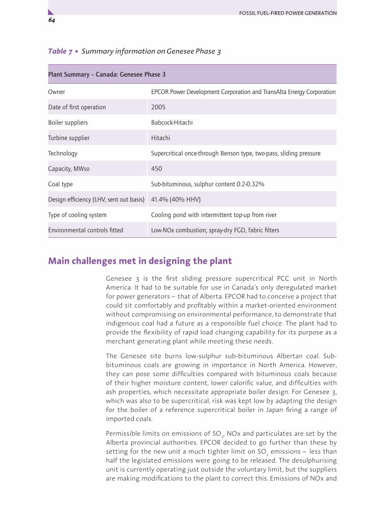
FOSSIL FUEL-FIRED POWER GENERATION 64x
Table 7 • Summary information on Genesee Phase 3
Plant Summary – Canada: Genesee Phase 3
Owner EPCOR Power Development Corporation and TransAlta Energy Corporation
Date of first operation 2005
Boiler suppliers Babcock-Hitachi
Turbine supplier Hitachi
Technology Supercritical once-through Benson type, two-pass, sliding pressure
Capacity, MWso 450
Coal type Sub-bituminous, sulphur content 0.2-0.32%
Design efficiency (LHV, sent out basis) 41.4% (40% HHV)
Type of cooling system Cooling pond with intermittent top-up from river
Environmental controls fitted Low-NOx combustion; spray-dry FGD, fabric filters
Main challenges met in designing the plant
Genesee 3 is the first sliding pressure supercritical PCC unit in North America. It had to be suitable for use in Canada’s only deregulated market for power generators – that of Alberta. EPCOR had to conceive a project that could sit comfortably and profitably within a market-oriented environment without compromising on environmental performance, to demonstrate that indigenous coal had a future as a responsible fuel choice. The plant had to provide the flexibility of rapid load changing capability for its purpose as a merchant generating plant while meeting these needs.
The Genesee site burns low-sulphur sub-bituminous Albertan coal. Sub-bituminous coals are growing in importance in North America. However, they can pose some difficulties compared with bituminous coals because of their higher moisture content, lower calorific value, and difficulties with ash properties, which necessitate appropriate boiler design. For Genesee 3, which was also to be supercritical, risk was kept low by adapting the design for the boiler of a reference supercritical boiler in Japan firing a range of imported coals.
Permissible limits on emissions of SO2, NOx and particulates are set by the Alberta provincial authorities. EPCOR decided to go further than these by setting for the new unit a much tighter limit on SO2 emissions – less than half the legislated emissions were going to be released. The desulphurising unit is currently operating just outside the voluntary limit, but the suppliers are making modifications to the plant to correct this. Emissions of NOx and

65Chapter 3 • Case Studies – Coal-Fired Plant 3: North America y
particulates are also far better than required by the authorities because of even better than design performance of the plant systems. In total, the company invested an additional USD 90 million on the Genesee 3 emissions control systems to significantly improve environmental performance compared with existing units at the site.
The suppliers were required to be able to construct the plant within a short timescale of 36 months. Accommodating the construction workforce, which peaked at 2100, placed added pressures on services at the remote site, including telephones, sewage and parking. One very practical response was to give workers the option of busing to work –many took advantage of the opportunity.
Overall configuration
The overall configuration is shown in Figure 12. The coal is burned in an opposed fired, two-pass boiler that was supplied by Babcock-Hitachi. NOx emissions are kept low by the use of a combination of 24 low-NOx burners and over-fire secondary air. After the boiler, a spray-dry flue gas desulphurisation unit cleans the flue gases by injection of lime slurry, and a bag filtration system collects the ash and spent absorbent.
The boiler converts water to superheated supercritical steam in a single pass. The steam is expanded in a supercritical turbine supplied by Hitachi, reheated in the boiler, then expanded again, before being condensed and returned as water to the boiler. The compact turbine arrangement features a compound high and intermediate pressure turbine plus a single double-flow low pressure turbine. Steam parameters are 25MPa/570°C/568°C. The condenser is cooled with water from a man made cooling pond in place of a tower. The water is returned to the cooling pond and gradually cools on its way back towards the plant intake. The pond is topped up intermittently by water from the North Saskatchewan River.
Figure 12 • Overall configuration of Genesee Phase 3
Cou
rtes
y EP
CO
R G
ener
atio
n an
d Tr
ansA
lta
Supercritical boiler
Spray dryer absorber module
Air heater
Flue gas duct
Elevator
Lime siloFabric fiber (dust collector)
StackInduced
draft fan

FOSSIL FUEL-FIRED POWER GENERATION 66x
Table 8 • Selected performance-related information on Genesee Phase 3
Annual operating efficiency (LHV, sent out basis) 41% (39.6% HHV basis)
Fuel calorific value (a.r.), MJ/kg LHV and HHV 17.3 (17.9 HHV)
Fuel ash content (a.r.), % 19.4
Fuel moisture content (a.r.), % 20
Fuel sulphur content (a.r.), % 0.2
Gross power output, MWe, at MCR 495 (496 actual)
Net power output, MWso, at MCR 450 (458 actual)
Auxiliary power consumption, MWe at MCR 44 (38 actual)
Main boiler feed pump drive (motor or turbine) motor
Steam conditions 25 MPa/570C°/568°C at boiler
Feedwater heating stages 4 LP + deaerator + 3 HP
Final feedwater temperature, °C 280
Type of cooling system, water temperature, °C Cooling pond, 18°C inlet
Condenser pressure, kPa 5
NOx abatement systems low-NOx combustors, over-fire air
NOx emissions, 6% O2, dry 65 ng/J achieved (~170 mg/m3)
Desulphurisation system spray-dry FGD
SO2 emissions, 6% O2, dry 295 mg/m3 achieved
Particulates removal system Fabric filtration
Particulates emissions, 6% O2, dry 19 mg/m3 achieved
Specific capital cost, USD/kWso ~1100 (2005) excluding IDC and owner’s costs
The plant’s own power consumption is low (and better than design), contributing to its high efficiency.
Plant description
Coal reception, handling and preparation
At the opencast (surface) mine, three main coal seams are exploited, the first of which lies below 25-30 m of overburden. Land is progressively reclaimed and put to farming use. The coal is supplied to the plant by 136 t capacity mine haul trucks. The trucks are also used to convey the ash from the power station to the mine for use as fill. The low-sulphur (0.2-0.32% S, a.r.) sub-bituminous coal is run-of-mine (ROM) and of variable size range. The coal

67Chapter 3 • Case Studies – Coal-Fired Plant 3: North America y
is stacked under cover in discrete piles to allow selective reclaiming for blending in case of variability. There is also a four-month open, but grassed over, reserve pile at the plant.
Genesee 3’s coal handling system takes coal from the live storage area, using a combination of existing facilities and newly installed conveyors, to deliver the coal to six coal silos. The unit’s system is designed to handle 0 - 38 mm sub-bituminous coal, with a moisture content of 26% by weight. Each of the six storage silos supplies a grinding mill immediately below it. At nominal rating, five of the MPS vertical spindle roller mills are used to grind the coal.
Coal handling difficulties can sometimes arise in adverse weather conditions. The coal moisture content is usually around 20% or a little higher, but heavy rains can increase this, and for a period during 2006 caused an additional difficulty in apparently washing fine clay into the coal. This gave some sticking in hoppers and was believed to be a factor related to some fabric filter blinding that occurred.
Boiler combustion system
A supercritical sliding-pressure Babcock-Hitachi boiler was adopted, the first time this type of boiler has been used in North America. It offered high efficiency, flexible operation, and proven reliability with low NOx combustion technology that could meet requirements without the need for downstream flue gas NOx removal. Once-through sliding pressure designs such as this one allow start-up times to be reduced and low-load operation to be achieved stably. Only constant pressure supercritical boilers have previously been used in North America.
The two-pass Benson boiler has an opposed firing system, with 24 burners mounted on the front and rear walls of the furnace. The Babcock-Hitachi staged combustion NR3 low-NOx burners are supplied by the six mills, each fed by one storage silo. At plant maximum continuous rating (MCR), five mills are normally operating and one is spare. It is possible to reduce output to 50% rating on coal without support fuel, and, in principle, to 35% output. However in order to fit with operational constraints, EPCOR use natural gas support fuel below 50% MCR. Start up is on natural gas. The boiler is also supplied with over-fire air above the upper burners. This, together with the NR3 burners, gives effective NOx control and high burnout.
Boiler efficiency is 89.5 % (based on HHV) as determined recently. This is 2% points higher than design and equivalent to around 93% on an LHV basis.
The boiler is equipped with a water quenched bottom ash hopper. A drag link conveyor removes the material from the ash hopper to a clinker grinder for reduction to a uniform size before it is belt conveyed to a storage silo. Mine haul trucks return this furnace ash (and also fly ash) to the mined area, where it is used for fill.

FOSSIL FUEL-FIRED POWER GENERATION 68x
Boiler heat transfer surfaces
The evaporator tubing, as in all PCC boilers, is welded to form a membrane wall to the boiler. The evaporator is spiral wound, with internally ribbed tubes for high, uniform heat absorption, stable fluid flow and reduction of boiler plant pressure loss. During start-up, there is recirculation of separated water but this ceases under normal once-through operating conditions.
The superheater surfaces consist of pendant type secondary, tertiary and final superheaters in the high temperature zone and a horizontal type primary superheater in the low temperature zone. The reheater has a pendant type secondary stage and a horizontal type primary stage. The superheated steam temperature is controlled primarily by the feed water/fuel ratio and, for secondary control if there is variation in coal properties, by three spray type attemperators. Reheat steam temperature is controlled by parallel flow gas biasing dampers so that flue gas recirculation is not required. Reheat steam spray attemperators are installed for emergency use. The materials used in the pressure parts include P/T91 and 347 HFG.
Draught system
The boiler operates conventionally, i.e. slightly sub-atmospherically under balanced draught. A failure rate analysis showed that a single train of fans in the draught system would give sufficient availability for the unit. There is therefore one forced draught fan, one primary air fan and one induced draught fan. Air is drawn from the top of the boiler house (at 15 to 47°C, depending on season) by the forced draught (FD) fan and the primary air (PA) fan, which are situated at ground level. Both fans connect with the single regenerative (Ljungstrom type) tri-sector air preheater to provide heated air for combustion.
The preheated primary air, after tempering with cold primary air, dries and conveys the pulverised coal from the mills to the burners on the boiler. The preheated secondary air is admitted to the furnace from the windboxes as over-fire air to provide air staging. The air heater flue gas outlet temperature is 130°C.
Flue gas is drawn through the boiler by the induced draught fan, which is placed downstream of the bag filters, just before the stack. A new 138 m concrete stack was constructed for Genesee 3. The stack is equipped with continuous emissions monitoring stations.
Emissions control equipment
NOx control
Combinations of combustion measures are used for NOx control. The staged combustion NR3 low-NOx burners are mounted in the furnace front and rear walls. Over-fire air is also introduced, and NOx emissions are low, in fact considerably better than design. The latter is 115 ng/J NOx (~300 mg/m3, at 6% O2, dry), whereas 65 ng/J is achieved (~170 mg/m3).

69Chapter 3 • Case Studies – Coal-Fired Plant 3: North America y
Flue gas desulphurisation
The spray-dry FGD system is designed to reduce SO2 emissions from the flue gas to EPCOR’s voluntary limit, which goes well beyond the provincial legislated requirements. The spray dry system was selected because it is less capital intensive than wet scrubbing, while able to provide the required residual levels of SO2 on this low sulphur coal. The system has two parallel absorber modules. The flue gas leaving the airheater enters near the base of the modules and exits at the top. A rotary atomiser sprays lime slurry into the gas stream to capture the SO2, and the reaction products and ash are collected in the downstream fabric filtration system. As is normal for such systems, part of the desulphurisation occurs in the bag filters on the collected solids. This is because some unused absorbent is collected together with the fly ash.
The spray-drier unit is currently (October 2006) operating slightly outside the voluntary limit, but the suppliers are making modifications to the plant to correct this and reach guaranteed desulphurisation levels. The plan is to recycle the ash and residual absorbent mixture from the spray drier outlet hopper back to the spray-drier inlet. This is also intended to solve a difficulty with wetness of the solids, which initially blinded some of the filters. It may also reduce the quantity of reagent required. The temporary departure from expectations appears to be related to coal quality variations. SO2 emissions are currently around 295 mg/m3 (at 6% O2, dry) and will be reduced to 240 mg/m3 when the guarantee value has been achieved.
Particulates and ash disposal
Most of the coal ash appears as fly ash. The particulates are removed from the flue gas after it exits the desulphurisation equipment by the fabric filtration system. The fabric filtration unit takes the concentration of particulates down to the very low level of 19 mg/m3 (at 6% O2, dry), which is better than design. The baghouse is equipped with an automatic, on-line bag cleaning system, which uses reverse pulses of compressed air. Separate compartments in the fabric filter are sequentially cleaned. Dislodged filter cake is collected in hoppers below the baghouse.
A pneumatic conveying system transports fly ash from the baghouse hoppers beneath the filters (and boiler economiser hoppers) to the fly ash storage silo located outside the powerhouse. The fly ash, which contains sulphate from the flue gas desulphurisation process, cannot be sold for cement production but is fully utilised in reclaiming the land at the opencast mine. The coal delivery trucks return the ash and furnace ash to the mine site. The mine sites are being progressively turned over to agricultural use.
Steam turbine and water/steam system
The steam and water cycle is a single reheat condensing supercritical system. The Hitachi 495 MWe 3600 rpm steam turbine is an impulse type, tandem compound TCDF-40 machine with 40 inch (1015 mm) last stage blades. The turbine arrangement is shown in Figure 13.

FOSSIL FUEL-FIRED POWER GENERATION 70x
Figure 13 • Genesee 3 Turbine
High-pressure (HP) and intermediate-pressure (IP) sections are arranged in one high and intermediate (HIP) outer casing with opposed flow directions to minimise thrust on the shaft. The HP steam initially enters the turbine near the middle of the HIP outer casing and flows through the HP stages toward the end of the unit. The reheated steam again enters to the turbine near the middle of the HIP outer casing. The steam then flows toward the generator end through the IP stages. After passing through the cross-over piping, the steam flows through the low-pressure turbine cylinder and exhausts to the condenser. The turbine is equipped for extraction of steam for feedwater heating. Main steam conditions are 25 MPa/570C°/568°C. The turbine is designed for sliding pressure operation to maintain efficiency as high as possible at reduced load. However, the unit generally runs at rated output.
The low pressure turbine has a water cooled condenser mounted beneath it where the wet steam emerging from the turbine (at 5 kPa) is fully condensed to water. The condenser consists of two shell and tube heat exchangers and it also incorporates the first low pressure feedwater heater. Steam flows over the tube bundles which carry the cooling water, pumped by two cooling water pumps from the adjacent man-made cooling pond. The water is returned to the cooling pond, and takes several days to traverse the circuit, over which time cooling occurs mainly due to evaporation and convection. Makeup water is pumped from the North Saskatchewan River.
The feedwater heating circuit has eight stages of bleed steam heating: four low pressure (LP) heaters, a deaerator combined with storage tank, and three high pressure (HP) heaters. Two parallel boiler feedwater pumps pump the feedwater from the storage tank to the high pressure required at the boiler inlet on the economiser. A third pump is available as reserve. These pumps
Cou
rtes
y EP
CO
R/Tr
ansA
lta
Low-pressure turbine
Water boxCooling water in
Crossover steam pipeShaft coupling
Intermediate-pressure turbineIntermediate-pressure steam from reheater
High-pressure steam from superheaterHigh-pressure steam nozzle ring
High-pressure turbineShaft seal
Bearing
Speed encoder
Intermediate-pressure steam to reheaterIntermediate-pressure steam from reheater
Cooling water out
Low-pressure feedwater heater 1
Condenser shell
Tube sheets
Condenser tubes
Exhaust steamInboard bearing
RotorRotor windings
Bush gear
Outboard bearingStator windings
Generator statorCooling channels
Turbine gear motor
Turbine Generator
71Chapter 3 • Case Studies – Coal-Fired Plant 3: North America y
are electrically driven and variable in speed using fluid couplings. Variable speed motors were not selected for this plant with their higher investment cost as high loading is anticipated.
Full flow condensate polishing systems are needed in once-through boiler plants to remove impurities from the boiler feedwater flow to prevent corrosion. Water purity was of great concern to EPCOR because of the selection of high steam parameters and EPCOR’s previous lack of operating experience with once-through boiler systems.
EconomicsThe cost of Genesee phase 3 was approximately 1100 USD/kWso in 2005, including the powerhouse EPC contract and balance of plant, but not interest during construction or other owners costs. Construction took 36 months. The unit was built within the existing power plant boundary. Capacity factor has been 93%. The plant operates primarily on base load, with some cycling between 75% and 100%.
Since Genesee 3 had to be a merchant plant able to compete in the open market environment of Alberta, the project team developed the scope of work under guide-lines that maintained as key the requirement to secure a plant of high reliability and availability. The design was based upon national and international standards to enable international purchasing, to avoid paying premiums for non standard products and construction was fast-tracked over a 36-month timeframe. This helped to mitigate the risk of developing in a deregulated market, and proved that coal plants can be built faster to compete with natural gas.
The power generating and emission control equipment was engineered, procured and constructed through a single EPC contract, including wrap-around guarantees for schedule and performance, with Hitachi Canada. The balance of plant, including all foundations, high voltage electrical system and switchyard and stack, were handled directly by EPCOR with Colt Engineering providing the engineering services. Genesee3 was completed on time, on budget and with an industry-leading safety record. This is noteworthy because, while Alberta’s oil sands sector is investing USD 84 billion in major construction, the industry is experiencing labour shortages and significant cost overruns.
Hitachi Canada used modular construction methods developed in Japan, involving fitting together complete sections of floors with many pre-installed components at ground level. Cranes then hoisted the assembled components up to be bolted in place. This typically allowed 20 to 30 components to be lifted into final position at the same time.
CommentaryThe Genesee 3 unit is the first of the new supercritical pulverised coal-fired plants to be constructed in North America. Previous units in the continent are from an earlier generation of the technology that was inflexible and tended

FOSSIL FUEL-FIRED POWER GENERATION 72x
to have high costs. Although large load swings are not anticipated on this plant, the sliding pressure design used here allows economically competitive, flexible plants that will be particularly suited to de-regulated environments in other parts of North America. This has been achieved without compromising efficiency or environmental performance.
The establishment of the Genesee Phase 3 project is an important milestone in the establishment of modern supercritical technology in North America. It has been a low-risk way of achieving high efficiency and environmental performance on sub-bituminous coals. After construction of a sister unit at a neighbouring TransAlta power generation site, later plants are likely to move to higher parameters, following the success of this and similar units currently being constructed in Canada and the USA.
Tailoring plant configuration to the requirements of the coal feed can result in low environmental impact while saving in cost. Thus, no SCR was needed, yet NOx emissions achieved are as low as ~170 mg/m3 at 6% oxygen, dry (much better than regulatory requirements). The low sulphur coal also enabled a spray dry type of FGD to be selected rather than more capital intensive wet scrubbers, while still meeting emissions requirements very easily. The latter also will have helped to keep plant own power consumption low. This is actually considerably better than design.
Future plansAs referred to earlier, a sister unit to Genesee 3 is to be built at one of TransAlta’s neighbouring power station sites and EPCOR plans to host the CCPC’s commercial scale demonstration of a gasification combined cycle with CO2 capture and storage at Genesee.
AcknowledgementsDavid Lewin, Senior Vice President, Environment, EPCOR, also for facilitatingTom Eley, EPCOR, Director, Generation Process OptimisationDavid Whitten, EPCOR, Generation Process OptimisationDarren Alessandrini, EPCOR, Manager, Resource Development Tech. ServicesTrevor Grams, Plant Manager, EPCOR, Genesee Generating StationGary Fulmore, Manager, Business Services, EPCOR, Genesee
Background sourcesWatanab S, Tani T, Takahashi M, Fujii H, 495-MW Capacity Genesee Power Generating Station Phase 3: First supercritical pressure coal-fired power plant in Canada. Available from: http://www.hitachi.com/rev/archive/2004/2011330_12604.html (2004) (accessed February 2006)
Acton J, Suzuki Y, Shimogori Y. 495-MW Capacity Genesee Power Generating Station Phase 3: The first supercritical pressure coal-fired power plant in Canada. Available from: http://www.hitachi.us/supportingdocs/forbus/powerindustrial/EP2005.pdf (2005) (accessed September 2006)

73Chapter 3 • Case Studies – Coal-Fired Plant 4: Asia y
COAL-FIRED PLANT ASIA
Bituminous coal-fired, coastal ultra-supercritical plant – Isogo New Unit 1, Japan
Introduction
Twenty ultra-supercritical pulverised coal units in Japan have been commissioned within the last twelve years, and this country, with Europe, leads the world in the development of the technology in its modern form with sliding pressure capability for operational flexibility. Forward-looking investments in Japan in producing advanced materials have enabled main superheated steam temperatures at the turbine to reach 600°C, with reheat to 610°C. These recent plants also have to meet the most stringent environmental requirements in the world and many can be regarded as leading examples of best practice.
Isogo New Unit 1 is a sea water cooled, 600 MWe unit, owned by Electric Power Development Co., which trades under the name of J-POWER. Isogo is located at Yokohama City, approximately 25 km southwest of Tokyo. The plant, which opened in April 2002, includes the first tower type once through boiler to be installed in Japan. Isogo New Unit 1, which replaced an earlier Isogo Unit 1, burns both Japanese and international bituminous coals as well as some sub-bituminous coal. Its efficiency, sent out, is 40.6% on an HHV basis, equivalent to over 42% on an LHV basis, which is good at a site with the rather warm sea water available there for cooling the turbine condenser.
Isogo New Unit 1’s environmental performance is also impressive. At the plant are installed a combination of environmental control systems, including a regenerable dry flue gas desulphurisation (FGD) system, to achieve very low levels of emissions. The technology is also a multi-pollutant control system and can be used to take out NOx and mercury, in addition to SO2. A sister unit (Isogo New Unit 2) being constructed alongside Isogo New Unit 1 will be installed to use the process as a multi-pollutant control system. The new unit will also employ a higher reheat temperature (620°C at the turbine).
4
Cou
rtes
y J-
POW
ER
Figure 14 • Isogo New Unit 1 general view

FOSSIL FUEL-FIRED POWER GENERATION 74x
Table 9 • Summary information on Isogo New Unit 1
Plant Summary – Japan: Isogo New Unit 1
Owner Electric Power Development Co. (J-POWER)
Date of first operation April 2002
Boiler suppliers Ishikawajima-Harima Heavy Industries (IHI)
Turbine supplier Fuji Electric (Siemens)
Technology Supercritical once-through, tower type, sliding pressure
Capacity, MWso 568
Coal type Bituminous, Japan and international
Design efficiency (LHV, sent out basis) 42% (40.6% HHV)
Type of cooling system Sea water
Environmental controls fitted SCR, ESP, FGD (dry type, regenerable activated coke)
Main challenges met in designing the plant
The main challenges at the plant were associated with the required limits to emissions of the main conventional pollutants, the use of very advanced steam conditions for high efficiency, and the need to keep the two then-existing units on-line while constructing Isogo New Unit 1 in a restricted area.
The power station lies in an urban setting. Permissible limits on emissions of oxides of sulphur, NOx and particulates are the responsibility of the Yokohama City authorities. The plant owners signed a pollution prevention agreement for the new unit that was much more stringent than previously committed for the older units at the site. The old Isogo 1 and 2 units had to meet very tight limits for the time, but New Unit 1 was committed to emissions levels that were one third of the previous for SO2, one eighth of the previous for NOx, and one fifth of the previous for particulates. In practice, it achieves even better performance than these levels.
The advanced steam parameters, chosen to maximise efficiency to save fuel costs and reduce all emissions including CO2, necessitated the use of state-of-the-art materials. The main and reheat steam conditions at the turbine of 25 MPa, 600°C and 610°C meant that even higher parameters needed to be withstood by the boiler pressure parts.
There was a need to establish the new unit at a busy power station site in a densely populated urban area. This required keeping the old units operating throughout the period of construction. The new unit, which generates more electricity than both of the two old units combined, was placed immediately adjacent to old units 1 and 2. Now, with Isogo New Unit 1 in operation, the old units have been dismantled, and a second new unit is being constructed

75Chapter 3 • Case Studies – Coal-Fired Plant 4: Asia y
where they stood, scheduled for opening in 2009. The limitation on space was the reason that it was decided to adopt a tower type boiler. Such boilers are taller than two-pass designs but the land area required is considerably less. This enabled sufficient space for lay-down and construction. The boiler-house height was reduced by adopting innovative design features in the boiler and by arranging for the boiler base level to be 5 m below ground level. The space constraint also led to the selection of the type of flue gas desulphurisation unit. The activated coke regenerable system occupies less area than wet limestone scrubbers (and has lower water consumption and waste water outflow).
Overall configuration
Isogo New Unit 1 has been designed to use international coals and Japanese coals. The coal is burned in a wall-fired tower boiler supplied by Ishikawajima-Harima Heavy Industries (IHI). Primary NOx emissions are kept low by the use of a combination of low-NOx burners and over-fire secondary air. After the boiler, an SCR unit removes further NOx, electrostatic precipitators remove dust, and a regenerable activated coke flue gas desulphurisation system removes SO2 from the flue gases before they reach the 200m stack, which is of an elliptical design to minimise skyline intrusion.
The boiler converts water to superheated supercritical steam in a single pass. The steam is expanded in an ultra-supercritical turbine supplied by Fuji Electric (Siemens), reheated in the boiler, then expanded again, before being condensed and returned as water to the boiler. Steam parameters are 25.0 MPa/600°C/610°C. The condenser is cooled with sea water, which in this part of the world allows a condenser pressure of 5 kPa at the design conditions.
The plant’s own power consumption is about 5% of gross generated power, which is low partly because of the use of turbine driven feed pumps and partly from the use of innovative systems such as the dry FGD system.
Plant description
Coal reception, handling and preparation
Isogo New Unit 1 has been designed to use international coals and Japanese coals. There are facilities for blending the international supplies as necessary. Imported coal is unloaded at facilities at Sodegaura on the other side of the bay and Ougishima to minimise dust and is then brought to the power station wharf in 5000 t dead weight ships. When the second new unit is opened, special 6000 tonne dead weight self-unloading ships will be used for bringing the coal in, saving on space. From the power station wharf, the coal is conveyed to four silos. The storage silos, each of capacity 25,000 t, are filled and unloaded using enclosed conveyors that use compressed air to support the conveyor belt. The system reduces noise and eliminates fugitive coal dust emissions. The coal is conveyed from the silos to bunkers above four vertical spindle roller mills, incorporating rotary classifiers, adjacent to the boiler.
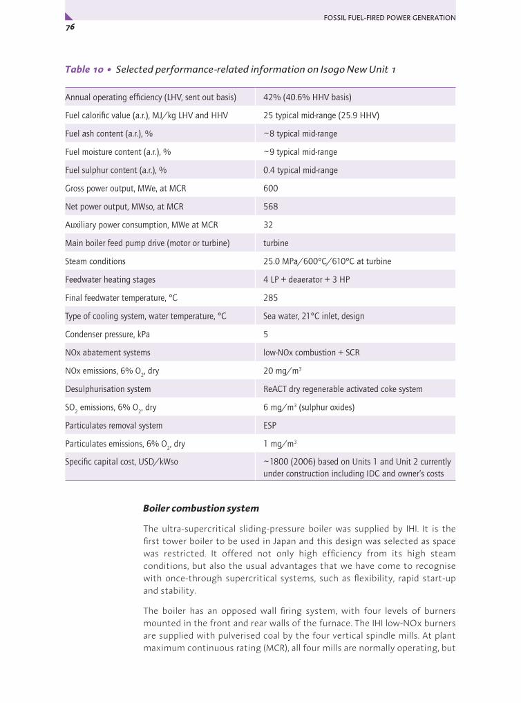
FOSSIL FUEL-FIRED POWER GENERATION 76x
Table 10 • Selected performance-related information on Isogo New Unit 1
Annual operating efficiency (LHV, sent out basis) 42% (40.6% HHV basis)
Fuel calorific value (a.r.), MJ/kg LHV and HHV 25 typical mid-range (25.9 HHV)
Fuel ash content (a.r.), % ~8 typical mid-range
Fuel moisture content (a.r.), % ~9 typical mid-range
Fuel sulphur content (a.r.), % 0.4 typical mid-range
Gross power output, MWe, at MCR 600
Net power output, MWso, at MCR 568
Auxiliary power consumption, MWe at MCR 32
Main boiler feed pump drive (motor or turbine) turbine
Steam conditions 25.0 MPa/600°C/610°C at turbine
Feedwater heating stages 4 LP + deaerator + 3 HP
Final feedwater temperature, °C 285
Type of cooling system, water temperature, °C Sea water, 21°C inlet, design
Condenser pressure, kPa 5
NOx abatement systems low-NOx combustion + SCR
NOx emissions, 6% O2, dry 20 mg/m3
Desulphurisation system ReACT dry regenerable activated coke system
SO2 emissions, 6% O2, dry 6 mg/m3 (sulphur oxides)
Particulates removal system ESP
Particulates emissions, 6% O2, dry 1 mg/m3
Specific capital cost, USD/kWso ~1800 (2006) based on Units 1 and Unit 2 currently under construction including IDC and owner’s costs
Boiler combustion system
The ultra-supercritical sliding-pressure boiler was supplied by IHI. It is the first tower boiler to be used in Japan and this design was selected as space was restricted. It offered not only high efficiency from its high steam conditions, but also the usual advantages that we have come to recognise with once-through supercritical systems, such as flexibility, rapid start-up and stability.
The boiler has an opposed wall firing system, with four levels of burners mounted in the front and rear walls of the furnace. The IHI low-NOx burners are supplied with pulverised coal by the four vertical spindle mills. At plant maximum continuous rating (MCR), all four mills are normally operating, but

77Chapter 3 • Case Studies – Coal-Fired Plant 4: Asia y
the mills are sized to enable full output to be achieved with only three in use. It is possible to reduce burner output down to 35% MCR, accompanied by sliding steam pressure to maintain optimum efficiency. Start up is on light fuel oil. Unlike HFO, this has little vanadium, and so is less harmful to the very high temperature heat transfer surfaces in the boiler.
The boiler is also supplied with over-fire air above the upper burners. This, together with the low-NOx burners, gives effective primary NOx control and high burnout. Boiler thermal efficiency is 88.5% on an HHV basis, equivalent to about 92% on an LHV basis.
Boiler heat transfer surfaces
Figure 15 shows the location of the heat transfer surfaces. The evaporator tubing, as in all PCC boilers, is welded to form a membrane wall to the boiler. The evaporator is spiral wound to ensure efficient heat transfer by giving an increased water flow and greater cooling, with a more uniform temperature distribution, so ensuring tube integrity. The interior surface of the tubing is smooth. During start-up, water is recirculated but under normal conditions the boiler, being ultra-supercritical, operates on a once-through system.
The superheater surfaces consist of ASME CC 2328 steels to handle the very high conditions (27.5 MPa/605°C at the outlet). The superheated steam temperature is controlled by spray type attemperators. Main steam pipework is fabricated from the advanced martensitic steel P122. Reheat steam temperature is controlled by parallel gas dampers, with spray attemperation not normally used.
Draught system
The boiler operates conventionally, i.e. slightly sub-atmospherically under balanced draught with forced draught, primary air and two induced draught fans. Combustion air streams supplied by the forced draught fan and the primary air fan pass through a steam air preheater before reaching the main regenerative (Ljungstrom type) tri-sector air preheater to provide heated air for combustion. The steam air preheater is used to add heat only as necessary to ensure that the main airheater elements do not become too cool (below 134°C) under certain conditions in winter, to avoid corrosion.
The single tri-sector rotary airheater extracts heat from the combustion gases leaving the boiler after they have passed through the selective catalytic reduction unit used for secondary NOx control. The preheated primary air, after tempering, dries and conveys the pulverised coal from the mills to the burners on the boiler. The preheated secondary air is admitted to the furnace as over-fire air to provide air staging.
The temperature of the flue gas at the outlet to the air heater is approximately 140°C. It divides into two parallel streams for particulate removal by electrostatic precipitators. The gas outflows from the precipitators go to two induced draught fans located ahead of the desulphurisation system.

FOSSIL FUEL-FIRED POWER GENERATION 78x
Figure 15 • Isogo New Unit 1 boiler heat transfer surfaces, SCR and air heaters
Emissions control equipment
Environmental performance of Isogo New Unit 1 is exceptional. If carbon dioxide levels are not included, the plant is a near-zero emission plant. Emissions are exceedingly low, being only one tenth of the stringent design levels for SO2 and dust, and one half of the NOx design level.
Cou
rtes
y J-
POW
ER
ECO
ECO
SH
Steam separator
RH
RH
SH
Steam/ air heater
SCR
Air heater

79Chapter 3 • Case Studies – Coal-Fired Plant 4: Asia y
NOx control
Combinations of combustion measures and flue gas treatment are used for NOx control. Low-NOx combustors and air staging in the boiler provide initial NOx minimisation, then a selective catalytic reduction system (SCR) removes 87.5% of the NOx leaving the boiler. The SCR unit is closely integrated with the boiler, being mounted just above the rotary airheater flue gas inlet. As it is also upstream of the electrostatic precipitators, it is known as a high-dust SCR system. In addition, the dry desulphurisation system, described later, captures more NOx. The design value NOx for emissions at the stack is 20 ppm, but in practice 10 ppm is achieved (20 mg/m3, at 6% O2, dry).
Particulates
Particulates are removed from the flue gas by the electrostatic precipitators, which are designed to allow no more than a very low 10 mg/m3 emission at the stack. However, in practice, performance is an order of magnitude better, and the concentration of particulates at the stack is extremely low at 1 mg/m3 (at 6% O2, dry). One of the reasons for this is that the downstream flue gas desulphurisation system also catches a substantial proportion of the remaining particulates. Almost the entire production of ash is utilised in cement applications and for production of a potassium silicate based fertiliser for sale.
Flue gas desulphurisation
The flue gas desulphurisation system installed on Isogo New Unit 1 is a regenerable process which uses activated coke in a loop to capture the SO2. It is required to remove 95% of the oxides of sulphur from the flue gas at Isogo, but the process performs much better than this, and residual levels of SO2 in the stack gas are at the exceedingly low level of 6 mg/m3 (at 6% O2, dry). Sulphuric acid is produced as a by-product.
J-POWER has acquired the rights to the technology from Mitsui Mining Co. and is marketing it under the name of ReACT (Regenerative Activated Coke Technology) as a multi-pollutant control system. This is because it can also simultaneously reduce NOx by catalysing its reduction by ammonia to nitrogen (similar to the reaction in a SCR unit). It will also capture particulates, as well as heavy metals such as mercury in either elemental or ionic form. Some fine activated coke that cannot be recycled is suitable as a dioxin adsorption agent for incinerator off-gases. Like active carbon, the activated coke is made by steam activation of coal, but it is more resistant to abrasion and crushing.
The process flow at Isogo is shown in Figure 16. There are two linked, continuous desulphurisation and regeneration stages. The flue gases are drawn from the electrostatic precipitators by the induced draught fan, and then ammonia is added at the inlet to the desulphurisation tower, which has two component modules. The flue gas, at 150°C, is admitted into the base of each adsorber module, which contains a slowly down-flowing bed of the activated coke. The flue gas exits at the top at 125-150°C. SO2 and sulphur trioxide are adsorbed and converted on the surface of the activated coke to sulphuric acid and ammonium sulphate.

FOSSIL FUEL-FIRED POWER GENERATION 80x
Figure 16 • ReACT active coke dry desulphurisation system at Isogo New Unit 1
The used adsorbent leaving the base of the desulphurisation tower is then conveyed to the regenerator. The latter also works as moving bed. The SO2 is regenerated by heat, which breaks down the adsorbed sulphuric acid and ammonium sulphate. Heat is supplied indirectly – heat exchanger tubing transfers heat from hot gases produced in a light oil burner. The issuing stream of SO2-rich gas is sent to the by-product recovery stage for manufacture of sulphuric acid. The regenerator operates at a temperature of 450°C, so the regenerated coke is cooled in the lower part before exiting the regenerator. Regenerated activated coke, after fines removal, is returned to the adsorption reactor.
The system has a number of advantages over normal wet scrubbing systems for SO2 removal. It consumes far less water (only 10% as much), consumes 80% as much power and is regenerable. Although this equipment was installed at Isogo New Unit 1 specifically for desulphurisation, additional particulates and some additional NOx are captured, and, as discussed above, the process is capable of removing other species. Isogo New Unit 2, currently under construction, will have the ReACT process installed specifically as a multi-pollutant control system. The process is being marketed in the USA with focus on capturing heavy metals including mercury.
Steam turbine and water/steam system
The steam and water cycle of Isogo New Unit 1 is a single reheat condensing supercritical system of conventional configuration but using advanced steam parameters. The Fuji Electric (Siemens design) 600 MWe 3000 rpm steam
Cou
rtes
y J-
POW
ER
Regenerationtower
�Ä�¶“ƒ
Desulphurisationtower Stack
Sulphuric acid
Induceddraught fan
Air preheater
SOrichgas
2
Activatedcoke fines(powdered)
Sulphuric acidmanufacturing system
Waste water
Outletdustcollector
Activated coke
Coal ash silo
Denitrification system
Ammonia
Electrostaticprecipitator
Fly ash
For cement
Hg
ReACT
Off-gas
For fertiliser
Boiler

81Chapter 3 • Case Studies – Coal-Fired Plant 4: Asia y
turbine is a tandem compound machine with 3-D blading, sliding pressure capability and 45.3 inch (1150 mm) final stage rotor blades.
There is a one single-ended high-pressure turbine, one double flow intermediate pressure turbine and one double flow low pressure turbine with a large exhaust area because of the long blade length to give maximum expansion at optimum installation cost. The turbine is equipped for extraction of steam for eight stages of feedwater heating. Main steam conditions are 25 MPa/600°C/610°C. The turbine is designed for sliding pressure operation to maintain efficiency as high as possible at reduced load, although the unit has been operating on base load each year to date.
The low pressure turbine has a sea water cooled condenser mounted beneath it where the wet steam emerging from the turbine (at 5 kPa) is fully condensed to water. Steam flows over the tube bundles which carry the cooling sea water, pumped by the cooling water pumps. The system is designed to give no more than a 7°C rise in cooling water temperature to minimise environmental impact.
The feedwater heating circuit has eight stages of bleed steam heating: four low pressure (LP) heaters, a deaerator combined with storage tank, and three high pressure (HP) heaters. The turbine driven boiler feed pump pumps the feedwater from the storage tank to the high pressure required at the boiler inlet on the economiser.
Economics
The contracting strategy was to use owner design basic specification. The approximate capital cost was 1800 USD/kWso (2006), based on Isogo New Units 1 and 2 (latter not yet completed). The unit was built within the existing power plant boundary. The cost excludes the cost of decommissioning the old units 1 and 2 but it does include interest during construction and owner’s costs. The cost was in the upper range of costs among the case studies, but this can be attributed to the date of the cost (most up-to-date for an actual plant) and the following factors:
y requirement of new coal berth and silos for the site;
y requirement of cutting-edge flue gas treatment systems, due to strict local environment regulations;
y requirement of exceptionally high reliability of the plant;
y difficulty in construction, due to limited construction area; and
y new technologies such as a tower-type boiler with aseismatic design concepts membrane-type water treatment systems in order to save space.
Construction took 66 months, including construction of alternative ancillary facilities and removing original ancillary facilities. There are 28 operating staff on a 3-shift system. Availability is high, at 96.5%, excluding time operating on a weekly partial load regime called clinker pattern.

FOSSIL FUEL-FIRED POWER GENERATION 82x
CommentaryIsogo New Unit 1 is clearly a flagship plant. The owner’s philosophy is to use high technical specification to achieve the most cost-effective realisation of low environmental impact in power projects. This unit uses the highest steam parameters in the world for a modern sliding pressure system to achieve a net efficiency of 40.6% on an HHV basis, equivalent to over 42% on an LHV basis, at a site with moderately warm sea water cooling. The environmental performance is exceptional. Close to zero emissions of conventional pollutants have been achieved. Emissions are only one tenth of the stringent local requirement levels for oxides of sulphur and dust, and one half of the NOx design level.
Isogo New Unit 1 was constructed in a limited area within a busy power station site while keeping two existing units operating throughout the period of construction. The new unit was placed immediately adjacent to old units 1 and 2.
The enlightened environmental approach has been extended to all parts of the plant. Silos are used for coal storage, filled and unloaded using enclosed conveyors that use compressed air to support the conveyor belt. The whole system was designed to reduce noise and eliminate fugitive dust emissions. The sea water cooling system is designed to give no more than a 7°C rise in cooling water temperature to minimise environmental impact.
The flue gas desulphurisation system installed on Isogo New Unit 1 is a regenerable process using a form of activated coke that achieves an exceedingly low sulphur oxides emission level of 6 mg/m3 (at 6% O2, dry). Its other advantages include a very low water consumption and ability to be used as a multi-pollutant control system as it can also take out NOx, mercury and other species.
The capital cost of Isogo New Unit 1 was in the upper range of costs among the case studies, but the plant has very high technical specifications, very advanced steam parameters and exceptionally low emissions and there were site space constraints during construction. The Isogo New Unit 2, construction of which commenced in October 2005, will have even higher steam conditions than New Unit 1 (25 MPa/600°C/620°C at the turbine).
The owner, J-POWER, is interested in co-firing coal and biomass and has done trials on another unit in Japan.
AcknowledgementsAndrew Minchener, Principal Associate, IEA CCC, for making the visit and collecting dataKyohei Nakamura, J-POWER for discussions and facilitating visit and data collectionIsogo management and engineers for discussions and supplying data
Background sourcesJ-POWER Reborn - Isogo Thermal Power Station, J-POWER EPDC (August 2002)EPDC Isogo Thermal Power Station - Outline of Facilities, EPDC (c.2001)J-POWER ReACT Regenerative Activated Coke Technology. Advanced Multi-Pollutant Removal Technology for Flue Gas, J-POWER EnTech, Inc. (2005)

83Chapter 3 • Case Studies – Coal-Fired Plant 5: Asia y
COAL-FIRED PLANT ASIA
Bituminous coal-fired, coastal supercritical PCC plant – Younghung Thermal Power Plant, Republic of Korea
Introduction
In Korea, almost all coal used for power generation is imported, as there is no steam coal production except for small quantities of low-quality (high ash) anthracite. A number of supercritical PCC plants have been constructed in the last 10 years with steam parameters of 24.6 MPa/538°C /538°C. The newest plant designs are now moving toward higher conditions quite rapidly.
Younghung Thermal Power Plant is the most recently constructed coal-fired plant in Korea. Its first two units were opened in 2004, with steam parameters of 24.7 MPa/566°C/566°C. Younghung is owned by the Korean South-East Power Company (KOSEP), an independent generator established upon the privatisation of the industry in 2001. It is a coastal plant, sea water cooled, located at Incheon, approximately 50 km west of Seoul. The plant fires international bituminous coals and its design efficiency is over 43% net, LHV basis, equivalent to an estimated 41.9% net, HHV basis. Units 1 and 2 are both rated at a nominal 800 MWe. A combination of environmental control systems gives very good environmental performance.
Figure 17 • Younghung Thermal Power Plant general view
5
Cou
rtes
y KO
SEP
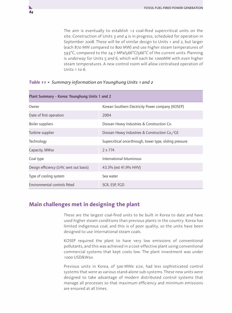
FOSSIL FUEL-FIRED POWER GENERATION 84x
The aim is eventually to establish 12 coal-fired supercritical units on the site. Construction of Units 3 and 4 is in progress, scheduled for operation in September 2008. These will be of similar design to Units 1 and 2, but larger (each 870 MW compared to 800 MW) and use higher steam temperatures of 593°C, compared to the 24.7 MPa/566°C/566°C of the current units. Planning is underway for Units 5 and 6, which will each be 1000MW with even higher steam temperatures. A new control room will allow centralised operation of Units 1 to 6.
Table 11 • Summary information on Younghung Units 1 and 2
Plant Summary – Korea: Younghung Units 1 and 2
Owner Korean Southern Electricity Power company (KOSEP)
Date of first operation 2004
Boiler suppliers Doosan Heavy Industries & Construction Co.
Turbine supplier Doosan Heavy Industries & Construction Co./GE
Technology Supercritical once-through, tower type, sliding pressure
Capacity, MWso 2 x 774
Coal type International bituminous
Design efficiency (LHV, sent out basis) 43.3% (est 41.9% HHV)
Type of cooling system Sea water
Environmental controls fitted SCR, ESP, FGD
Main challenges met in designing the plant
These are the largest coal-fired units to be built in Korea to date and have used higher steam conditions than previous plants in the country. Korea has limited indigenous coal, and this is of poor quality, so the units have been designed to use international steam coals.
KOSEP required the plant to have very low emissions of conventional pollutants, and this was achieved in a cost-effective plant using conventional commercial systems that kept costs low. The plant investment was under 1000 USD/kWso.
Previous units in Korea, of 500 MWe size, had less sophisticated control systems that were as various stand-alone sub-systems. These new units were designed to take advantage of modern distributed control systems that manage all processes so that maximum efficiency and minimum emissions are ensured at all times.

85Chapter 3 • Case Studies – Coal-Fired Plant 5: Asia y
Overall configurationIn each unit, the coal is burned in a two-pass boiler supplied by Doosan Heavy Industries & Construction Co. NOx from the furnace is minimised by the use of low-NOx burners and over-fire secondary air. After the boiler, an SCR unit removes more of the NOx, electrostatic precipitators remove dust, and a wet scrubbing flue gas desulphurisation system removes SO2 from the flue gases before they reach the stack.
The boiler converts water to superheated supercritical steam in a single pass. The steam is expanded in a supercritical turbine supplied by Doosan Heavy Industries & Construction Co./GE, reheated in the boiler, then expanded again, before being condensed and returned as water to the boiler. Steam parameters at the turbine are 24.7 MPa/566°C/566°C. The condenser is cooled with sea water, which in this part of the world allows a condenser pressure of 5 kPa at the design conditions.
Table 12 • Selected performance-related information on Younghung Units 1 and 2
Annual operating efficiency (LHV, sent out basis) 41% (est 39.7% HHV basis)
Fuel calorific value (a.r.), MJ/kg LHV and HHV 25 basis uncertain
Fuel ash content (a.r.), % 15
Fuel moisture content (a.r.), % 3
Fuel sulphur content (a.r.), % 0.6
Gross power output, MWe, at MCR 814
Net power output, MWso, at MCR 774
Auxiliary power consumption, MWe at MCR 40
Main boiler feed pump drive (motor or turbine) turbine
Steam conditions 24.7 MPa/566°C/566°C at turbine
Feedwater heating stages 7 LP + deaerator + 3 HP
Final feedwater temperature, °C 286
Type of cooling system, water temperature, °C Sea water, estimated 20°C inlet
Condenser pressure, kPa 5
NOx abatement systems low-NOx combustion + SCR
NOx emissions, 6% O2, dry 83 mg/m3
Desulphurisation system Wet FGD
SO2 emissions, 6% O2, dry 80 mg/m3
Particulates removal system ESP
Particulates emissions, 6% O2, dry 10 mg/m3
Specific capital cost, USD/kWso 993 (2003) basis uncertain
FOSSIL FUEL-FIRED POWER GENERATION 86x
Plant description
Coal reception, handling and preparation
Coal is unloaded at the neighbouring wharf and conveyed to the stockyard. Coal sources include Australia, Indonesia and India. All coal is blended to meet a tight specification and this was reported to constitute a considerable operational task. The coal is conveyed from storage to the bunkers above the vertical spindle mills adjacent to each boiler.
Boiler combustion system
For each unit, the supercritical sliding-pressure boiler was supplied by Doosan Heavy Industries & Construction Co (licensed Alstom technology, and engineering by KOPEC).
The low-NOx burners are supplied with pulverised coal by vertical spindle mills, the bunkers for which are supplied with the coal from the stockyard. The boiler is also supplied with over-fire air above the upper burners. This, together with the low-NOx burners, gives both effective initial NOx control and high burnout.
Boiler heat transfer surfaces
The evaporator tubing in the boiler is welded to form a membrane wall. The evaporator is spiral wound to ensure efficient heat transfer by giving an increased water flow and greater cooling to ensure tube integrity. Water is recirculated during start-up but not under normal once-through operation.
The economiser heating surfaces are located within the boiler flue gas path downstream of the primary superheater and reheater banks near to the exit of the boiler rear pass. The superheater is arranged in the conventional three stages: primary, secondary and final, with systems for temperature control by spray water addition (attemperation) between them. The primary superheater is located in the rear pass, above the economiser. The other two superheater sections are in the upper furnace. The reheater is located downstream of the final superheater. Reheat steam temperature is controlled by spray type attemperators. T91 martensitic steel was used for the final superheater.
Draught system
The boiler of each unit operates using the conventional balanced draught system, with forced draught and primary air fans supplying combustion air from the top of the boiler-house and induced draught fans drawing the flue gases from the boiler.
The primary and secondary combustion air flows of each unit are preheated using a tri-sector rotary Ljungstrom regenerative airheater that extracts heat from the combustion gases after they leave the selective catalytic reduction unit. The preheated primary air, after tempering with cold primary air, dries and conveys the pulverised coal from the mills to the burners on the
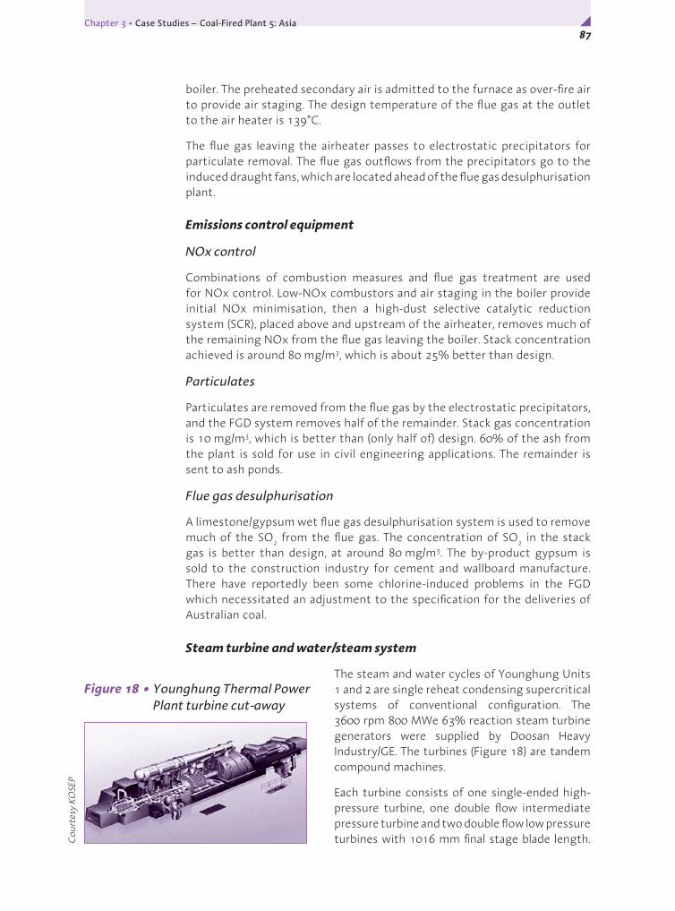
87Chapter 3 • Case Studies – Coal-Fired Plant 5: Asia y
boiler. The preheated secondary air is admitted to the furnace as over-fire air to provide air staging. The design temperature of the flue gas at the outlet to the air heater is 139°C.
The flue gas leaving the airheater passes to electrostatic precipitators for particulate removal. The flue gas outflows from the precipitators go to the induced draught fans, which are located ahead of the flue gas desulphurisation plant.
Emissions control equipment
NOx control
Combinations of combustion measures and flue gas treatment are used for NOx control. Low-NOx combustors and air staging in the boiler provide initial NOx minimisation, then a high-dust selective catalytic reduction system (SCR), placed above and upstream of the airheater, removes much of the remaining NOx from the flue gas leaving the boiler. Stack concentration achieved is around 80 mg/m3, which is about 25% better than design.
Particulates
Particulates are removed from the flue gas by the electrostatic precipitators, and the FGD system removes half of the remainder. Stack gas concentration is 10 mg/m3, which is better than (only half of) design. 60% of the ash from the plant is sold for use in civil engineering applications. The remainder is sent to ash ponds.
Flue gas desulphurisation
A limestone/gypsum wet flue gas desulphurisation system is used to remove much of the SO2 from the flue gas. The concentration of SO2 in the stack gas is better than design, at around 80 mg/m3. The by-product gypsum is sold to the construction industry for cement and wallboard manufacture. There have reportedly been some chlorine-induced problems in the FGD which necessitated an adjustment to the specification for the deliveries of Australian coal.
Steam turbine and water/steam system
The steam and water cycles of Younghung Units 1 and 2 are single reheat condensing supercritical systems of conventional configuration. The 3600 rpm 800 MWe 63% reaction steam turbine generators were supplied by Doosan Heavy Industry/GE. The turbines (Figure 18) are tandem compound machines.
Each turbine consists of one single-ended high-pressure turbine, one double flow intermediate pressure turbine and two double flow low pressure turbines with 1016 mm final stage blade length. C
ourt
esy
KOSE
P
Figure 18 • Younghung Thermal Power Plant turbine cut-away

FOSSIL FUEL-FIRED POWER GENERATION 88x
The turbine is equipped for extraction of steam for feedwater heating. Main steam conditions at the turbine are 24.7 MPa/566°C/566°C. The turbine is designed for sliding pressure operation (down to 30% MCR) to maintain efficiency as high as possible at reduced load, although the new units are naturally operating on base load currently. The boiler/turbine units can ramp at 3%/minute from 30% to 50% output, and at 5%/minute above 50% output. Each low pressure turbine has a sea water cooled condenser mounted beneath it, where the wet steam emerging from the turbine (at 5 kPa) is fully condensed to water.
The feedwater heating circuit has eleven stages of feedwater heating: seven low pressure (LP) heaters, a deaerator combined with storage tank, and three high pressure (HP) heaters. Final feedwater temperature is 286°C. A turbine driven boiler feed pump is used to pump the feedwater from the storage tank to the pressure required at the inlet to the economiser.
Plant control system
Younghung’s units have been designed to take advantage of modern distributed control systems that manage all processes so that maximum efficiency and minimum emissions are ensured at all times. The system features an Ethernet communications network, high speed PC-based controllers, and desktop operator consoles with state-of-the-art software. A new control room will allow centralised operation of Units 1 to 6.
Economics
The plant specific capital cost was reported to be 993 USD/kWso in 2003, but the basis is uncertain. Most key components were supplied by Korean companies. Construction time was 64 months. The units were constructed on a greenfield site. During the visit, it was stated that 150 persons operate all aspects of Units 1 and 2. The questionnaire reply indicated 52 operating staff, so this appears to exclude other staff activities at the site.
Commentary
The steam and water cycles at Younghung are single reheat condensing supercritical systems of conventional configuration. It is a coastal plant, sea water cooled, and the plant performs well. Efficiency is high, and own power consumption is less than 5% of gross power. The owners, KOSEP, required the plant to have very low emissions of conventional pollutants, and this was achieved in a cost-effective plant using conventional commercial systems that kept costs low. The plant investment was under 1000 USD/kWso.
The combination of environmental control systems gives very good environmental performance. Pollutant emissions are not only very low, they are considerably better than design, using conventional environmental control equipment of high performance. The new units have been designed to take advantage of modern integrated control and monitoring systems so that maximum efficiency and minimum emissions are ensured at all times.

89Chapter 3 • Case Studies – Coal-Fired Plant 5: Asia y
There is a policy to move gradually to higher steam parameters with succeeding coal-fired supercritical unit additions at the site. Units 1 and 2 have steam parameters at the turbine of 24.7 MPa/566°C/566°C. A total of twelve units is envisaged by the owners.
Acknowledgements
Andrew Minchener, Principal Associate, IEA CCC, for making the visit and collecting data
Nam-Ho Baek, Team Leader, Generation Management, Power Generation Department, KOSEP, for permitting the visit
Seong-Ki Lee, KOSEP, for hosting the visit and data provision
Seong Jegarl, KEPRI, for valuable liaison on data provision and assistance with the plant visit
Background sources
Peltier R, Yonghung Thermal Power Plant Units 1 & 2, Inchon, South Korea. Power, pp 78-83 (July/August, 2005)

FOSSIL FUEL-FIRED POWER GENERATION 90x
COAL-FIRED PLANT ASIA
Lean coal-fired, inland supercritical PCC plant – Wangqu 1 and 2, China
Introduction
China is currently experiencing an unprecedented expansion of its electricity supply industry. This expansion has pulverised coal-fired power generation at its base, with supercritical steam conditions as the norm because of its efficiency and emissions advantages. According to Doosan Babcock, some four hundred 600 MWe or larger supercritical units are expected to have been ordered by 2010. This is placing considerable strain on China’s mining industry, despite the country’s large coal resources. Often, the better quality coals go to steelmaking, so that there is growing pressure on the power stations to burn a much wider range of coals, to provide reliable supply. Lean coals – those with just 10 to 20% dry ash free volatiles – are thus being used more frequently for steam raising, but in the past they have presented a number of combustion challenges. This section describes how these challenges have been met by Doosan Babcock Energy Limited (formerly Mitsui Babcock) during the design of the 2 x 600 MWe supercritical units at Wangqu Power Station, Shanxi Province.
Table 13 • Summary information on Wangqu units 1 and 2
Plant Summary – China: Wangqu units 1 and 2
Owner Shanxi Lujin Wangqu Power Generation Co., Ltd
Date of first operation August 2006
Boiler supplier Doosan Babcock Energy Ltd
Turbine suppliers Hitachi
Technology Supercritical, Benson, two-pass, wall fired
Capacity, MWso 2 x 600 nominal
Coal type Chinese low volatile coal
Design efficiency (LHV, sent out basis) 41.4% (40% HHV)
Type of cooling system Water cooled, with cooling tower
Environmental controls fitted Advanced low-NOx burners with high velocity overfire air, ESP, FGD
6

91Chapter 3 • Case Studies – Coal-Fired Plant 6: Asia y
The plant, opened in 2006, and owned by Shanxi Lujin Wangqu Power Generation Co. Ltd, is at an inland location, 2 km north west of Lucheng City near Changzhi. Coal is sourced from the local mine, via 6 km rail and 10 km road connections, and is fired as-received. The units are expected to have a net efficiency of over 41% on an LHV basis, equivalent to 40% net, HHV basis. The owners intend eventually to establish a 2400 MW power plant on the site.
Main challenges met in designing the plant
China’s lean coals have presented a challenge for wall-fired boiler manufacturers for decades. Until now, suppliers have regarded application of wall-fired (and corner-fired) systems to lean coals as too difficult. Thus, normal coals have been fired readily in both wall-fired and corner-fired systems, but lean coals have traditionally only been fired in downshot systems to achieve sufficient flame stability and operational flexibility. Downshot systems have also not been regarded until recently as suited to use in supercritical boilers. These new wall-fired boilers at Wangqu therefore represent a major step forward in being among the first supercritical units to operate successfully using such coals. Outside the combustion zone, the boiler is a conventional, two gas-pass type, supercritical boiler, using a divided rear pass arrangement with biasing dampers for reheat temperature control. However, the combustion zone is different because of its components – advanced low NOx burners together with high velocity over-fire air – that were developed by Doosan Babcock to ensure this wall-fired system performed well on such a difficult fuel.
The other major challenge was NOx. Chinese NOx legislation does recognise coal quality as an issue, setting limits for new lean coal-fired plant at 650 mg/m3. Although this would be a difficult target for downshot furnaces, it is a realistic target for wall firing. In the mid-1990s, Doosan Babcock developed an advanced low NOx burner at its burner test facility giving a 25-30% improvement in NOx without loss of combustion efficiency. On plant, at 300 MWe scale, overall reductions in excess of 70% were realised. A visible flame stability improvement and the NOx potential made this burner in a wall fired furnace an obvious candidate for lean coal applications. Following initial development on UK coals, the system was refined to achieve the required NOx emissions on test coals from Wangqu by incorporating the use of high velocity over-fire air. Flame stability was also maintained down to 40% boiler maximum continuous rating (BMCR). Because it also gave improved mixing, use of the high velocity over-fire air also resulted in better combustion efficiency. Mill performance is critical, with dynamic classifiers in place to ensure no compromise on fineness. As a result, anticipated boiler efficiency is around 94% LHV, which in this instance is coupled with a NOx guarantee at 650 mg/m3 and a turndown guarantee at 40% boiler maximum continuous rating.
The pronounced stability of the burner has enabled the Wangqu furnace design to proceed without need for refractory. Earlier wall-fired attempts by others to fire these coals had included the use of burner zone refractory and slagging difficulties had been a significant issue.

FOSSIL FUEL-FIRED POWER GENERATION 92x
The combination of advanced low NOx burners and high velocity over-fire air is thus being used for the first time at Wangqu to maximise NOx control and combustion efficiency to achieve an overall performance not previously thought possible on such difficult coals, and, importantly, so paving the way for the more extensive use of lean coal for power generation purposes.
Overall configuration
The coal is burned in a wall-fired two-pass boiler designed and supplied by Doosan Babcock Energy Limited. NOx emissions are controlled by combustion measures, and electrostatic precipitators and wet limestone gypsum desulphurisation units further clean the emerging flue gas. As with all supercritical boiler plants, the Wangqu boilers operate in once-through mode: feedwater is heated then converted totally to superheated supercritical steam in a single pass within the boiler.
Table 14 • Selected performance-related information on Wangqu units 1 and 2
Operating efficiency (LHV, sent out basis) 41.4% design (40% HHV basis) (not an annual value)
Fuel calorific value (a.r.), MJ/kg LHV and HHV 23.6 (24.6 HHV)
Fuel ash content (a.r.), % 22.3
Fuel moisture content (a.r.), % 8
Fuel sulphur content (a.r.), % 0.27-1.2
Gross power output, MWe, at MCR 672
Net power output, MWso, at MCR 600 nominal; 620+ achievable
Auxiliary power consumption, MWe at MCR ~6% of gross output
Main boiler feed pump drive (motor or turbine) turbine
Steam conditions 24.2 MPa/566°C/566°C at turbine
Feedwater heating stages 4 LP + deaerator + 3 HP
Final feedwater temperature, °C 289
Type of cooling system, water temperature, °C Water, cooling tower, estimated 21°C at inlet
Condenser pressure, kPa 4.4-5.4
NOx abatement systems low-NOx axial swirl burners plus over-fire air
NOx emissions, 6% O2, dry 650 mg/m3
Desulphurisation system Wet limestone scrubbers
SO2 emissions, 6% O2, dry 25 ppm design ~70 mg/m3
Particulates removal system ESP
Particulates emissions, 6% O2, dry 50 mg/m3
Specific capital cost, USD/kWso ~580 (2006) excluding IDC and owner’s costs

93Chapter 3 • Case Studies – Coal-Fired Plant 6: Asia y
The steam is expanded in a supercritical turbine, reheated, further expanded, then condensed and the water returned to the boiler. Each boiler serves a Hitachi TC4F-40 supercritical steam turbine generator employing steam parameters of 24.2 MPa/566°C/566°C. Although the plant is nominally rated at 600 MWe net, a net output of 671 MWe can be achieved on a continuous basis.
The condenser is cooled with recirculating water that is cooled using a natural draught cooling tower.
Plant description
Coal reception, handling and preparation
Coal is supplied to the plant by rail and road from the neighbouring mine to the stockyard, from where it is transported by conveyors to the bunkers. Each boiler has six coal bunkers, each with a gravimetric feeder to meter the
coal feed to its associated vertical spindle roller mill of MPS design. The six mills (see Figure 19) are fitted with dynamic classifiers to ensure correct coal fineness for design burner performance. From the mills the PF is transported by the primary air to the burners. Each mill supplies five burners. The mill outlet temperature is controlled by mixing hot primary air from the airheaters with cooler air. To achieve boiler maximum continuous rating on the design coal, 5 mills are required in service (25 burners operating in total).
Boiler combustion system
Fuel combustion is achieved by the use of thirty Doosan Babcock Mark V low-NOx axial swirl burners (LNASB) and sixteen high velocity over-fire air (OFA) ports. The configuration comprises three horizontal rows of five burners on the front wall, with the five OFA ports forming a separate horizontal row above the top row of burners, and a similar arrangement on the rear wall. The burners are arranged in a chequer board pattern on the front and rear furnace walls. Alternate burners impart either a clockwise or an anti-clockwise direction of swirl. Each side wall also has three over-fire air (or after air) ports equally spaced. The use of OFA ports allows the boiler combustion system to utilise furnace air staging for further NOx reduction. The burner zone is maintained fuel rich with less than the stoichiometric air requirement, and the OFA ports zone has the balance of supplied combustion air.
Cou
rtes
y D
oosa
n Ba
bcoc
k
Figure 19 • The mill bay of one of the Wangqu units
FOSSIL FUEL-FIRED POWER GENERATION 94x
The LNASB provides an effective, economic means of achieving NOx reduction by the introduction of the axial generation of swirl to the various air streams. This provides a simple and robust design, without the need for the large number of mechanical links associated with other systems. Combustion air is divided into four streams, primary, secondary, tertiary and quaternary, and separate windboxes serve as common manifolds to each row of 5 LNASB for the supply of each of these air streams. The air flows are admitted via concentric tubes, ensuring staged combustion with virtually complete fuel utilisation. The central core air tube has a fuel oil gun and igniter running through its centre.
Boiler heat transfer surfaces
The boiler-turbine units are designed for sliding pressure operation for load variation without undue efficiency loss.
Economiser
High pressure feedwater from the high pressure feedwater heating system is sent to the boiler economiser. The economiser heating surfaces are located within the boiler flue gas path downstream of the primary superheater and reheater banks near to the exit of the boiler within two damper controlled parallel rear passes. A plate-gilled (steel-finned) tube economiser design was employed at Wangqu to give a saving in weight and number of tubes, to facilitate fabrication and to aid cleaning.
Evaporator
The evaporator circuit takes the high pressure pre-heated water from the economiser. A spiral wound tube arrangement in the zone near to the coal burners is used in once-through boilers such as here to give a long path and high flow in the tube sections for efficient cooling to prevent damage. Internally rifled tube designs with vertical tubing, e.g. the Doosan Babcock Posiflow™ boiler, are also now available, which have the advantages of lower feedwater flow rates in each tube and hence reduced pumping power requirements, whilst still maintaining adequate tube cooling under all operating conditions. At Wangqu, the furnace waterwalls were site assembled from shop fabricated panels to give the spiral formation. Above the level of the furnace arch, the evaporator consists of vertical tubes. Pipes transport the steam to four separator vessels. During start-up and at low output, water is separated from the wet steam by the separators and recirculated to ensure a minimum flow of water in the boiler. In normal operation, there is no recirculation.
Superheaters
Figure 20 shows the locations of the superheater tubing in the boilers. The superheaters take steam from the evaporator and convert it to high pressure, high temperature steam (24.8 MPa /571°C) for sending on to the turbine. The superheater is arranged in three stages: primary, secondary platen (flat

95Chapter 3 • Case Studies – Coal-Fired Plant 6: Asia y
panel) and final, with systems for temperature control by spray water addition (attemperation) between them. The primary superheater is located in one of the rear passes, above the economiser section in that pass. The steam leaves the primary superheater outlet in two streams, each of which pass through attemperators and cross over to the other side of the boiler to feed the two secondary platen superheater inlets. These are single loop pendant elements located in the upper furnace on a wide pitch to avoid the formation of slag deposits or bridging. After the next stage of attemperation, the parallel streams pass through the pendant final superheaters. Materials used for the high temperature superheater and reheater tubing were T91 and TP347H.
Figure 20 • Wangqu boiler outline showing location of primary, secondary platen and final superheaters
Cou
rtes
y D
oosa
n Ba
bcoc
k
Main steam outlet
Final superheater
Platen superheater
Primary superheater

FOSSIL FUEL-FIRED POWER GENERATION 96x
Reheater
The single stream reheater takes partially expanded steam from the HP turbine exhaust and reheats it before returning it to the inlet of the intermediate turbine for further expansion. The reheater consists of a pendant section, located downstream of the final superheater, and horizontal serpentine banks in the rear pass in parallel with the pass containing the primary superheater. Reheat steam temperature (569°C) is normally controlled by regulating (biasing) the gas flow between the reheater and superheater bank sections in the boiler rear pass. If necessary, spray water injection upstream of the reheater inlet can be used. Reheat steam spray attemperation is not required under normal operation.
Draught systems
The boilers operate at slightly below atmospheric pressure under conventional balanced draught conditions. On each boiler, two parallel 50% capacity primary air (PA) fans, taking suction from atmosphere, supply part of the combustion air and use it to convey the pulverised coal from the mills to the burners. The primary air is preheated before reaching the mills to dry the coal as it is transported. The secondary air system supplies the majority of the combustion air and this is also preheated. Each boiler has two parallel secondary air ducts, each with a 50% capacity forced draught fan. Most of the heating duty is carried out in a rotary Ljungstrom type regenerative airheater, that extracts heat from the flue gases leaving the boiler. Flue gas exit temperature is 118°C. A steam airheater is also included in case needed to maintain a sufficiently high temperature within the rotary heater, to avoid corrosion problems. There is a take off from the secondary air to the high velocity over-fire air system.
Flue gas is drawn from the convective section of the boiler by two 50% capacity induced draught (ID) fans placed downstream of the particulate removal system. The ID fans connect, via ducting, with the flue gas desulphurisation (FGD) plant. There is a bypass damper so that, if necessary, flue gas can be sent directly to the stack.
Emissions control equipment
The units are fitted with electrostatic precipitators and wet scrubbing flue gas desulphurisation (FGD) systems. Limestone for the latter is supplied from local sources. SO2 emissions limits are 25 ppm (equivalent to around 70 mg/m3). The FGD units were supplied by IHI. Efficiency is high: the SO2 removal design efficiency is 97% for coals with sulphur contents up to 1.2 %. The sulphur content of the design coal is <0.5% and there were no measurable SO2 emissions at the time of the plant visit (September, 2006).
The owners are understood to be committed to installing a selective catalytic reduction (SCR) system for final NOx control, despite the fact that the Doosan Babcock low NOx burners will meet current Chinese emissions standards. This is believed to be connected with the conditions of the loan by the Japanese bank, which appear to require that Japanese performance

97Chapter 3 • Case Studies – Coal-Fired Plant 6: Asia y
and emissions standards be met wherever feasible. This nevertheless does not detract from the value and achievement of the Doosan Babcock low-NOx combustion technology.
Ash handling systems
90% of the fly ash generated is removed in electrostatic precipitators, 5% in the economiser and the balance in the rotary air preheaters. The fly ash handling system is designed to aid transportation of the ash at low velocities and high densities to reduce cost by minimising wear and allowing less expensive steels to be used.
Boiler ash is discharged into a water filled slag hopper where it cools and collects until discharged at set time intervals into dewatering bins.
Steam turbine and water/steam system
The steam and water cycle is a conventional supercritical one. The 3000 rpm steam turbine connected to each boiler unit at Wangqu is a tandem compound TC4F-40 model supplied by Hitachi. This has a high pressure and intermediate pressure turbine in one casing plus two double-flow low pressure cylinders with 40 inch (1020 mm) length final stage blades. Turbine maximum continuous rating is 646 MW. The turbine is designed for sliding pressure operation for high efficiency at reduced output.
The turbine parameters were chosen by the client to be slightly conservative to minimise risk, while still giving good plant performance. 1020 mm last stage blades, which allow a higher efficiency compared with older designs using shorter blade lengths, are also well proven now for 50 Hz machines. A trade-off between size and cost exists but it is generally more economic to increase the LP turbine annulus area by maximising the last stage blade length rather than to multiply the number of cylinders. Main steam inlet conditions are 24.2 MPa/566°C, with reheat to 566°C. The condenser pressure is 4.4-5.4 kPa. Hitachi now offer for 50 Hz and 60 Hz 1000 MWe tandem compound turbines with 25 MPa/600°C main steam and 600°C reheat steam, parameters now commonly adopted in Japan, with blade lengths up to 43 inches (1090 mm). Previously, 1000 MWe turbines have had to have multiple shafts (in cross-compound arrangement). The Japanese turbine manufacturers appear to favour keeping to slightly lower pressures than the European supercritical turbine manufacturers.
In the water/steam cycle, water is extracted from the condenser beneath the turbine by the condensate pumps and sent through four stages of low pressure feedwater heating to the storage vessel/deaerator unit, which also acts as the fifth low pressure heater. The main boiler feed pump then extracts the water from the deaerator, pumping it via three high pressure feedwater heaters, to the economiser on the boiler. The final feed-water temperature at the inlet of the economiser is nominally 289°C. The boiler feed pump is driven by its own dedicated turbine. Intermediate pressure steam for this is taken from the main turbine. Steam is also extracted at various pressures for sending to the feedwater heaters.

FOSSIL FUEL-FIRED POWER GENERATION 98x
Each low pressure turbine has a water cooled condenser mounted beneath it where the wet steam emerging from the turbine is fully condensed to water. Cooling water for the condensers comes from a closed loop system with conventional natural draught cooling towers (one for each boiler-turbine unit) used to cool the recirculating cooling water by partial evaporation. A reservoir tops up the cooling water system.
Economics
The contracting strategy used by the client was owner design specification and the plant installation cost was approximately 580 USD/kWso in 2006. In China project costs and accounts are derived somewhat differently to western practices but this is understood to exclude owner’s costs and interest during construction. Notice to proceed was given in November 2003, and unit 1 started operation in May 2006 (30 months later). The Doosan Babcock boilers took around one year to erect on this greenfield site. There are 120 operating staff.
Commentary
The boilers at Wangqu have surmounted a barrier in being among the first supercritical units to operate using China’s low volatile lean coals. Downshot firing had previously been regarded as necessary for these coals, limiting scope for supercritical designs. However, attention to burner development and other details of combustion equipment design have allowed NOx emissions and fuel combustion efficiency to be optimised to a degree not previously possible in wall-fired units. The success paves the way for the more extensive use of lean coal for power generation.
Wangqu was reported at the time of the site visit to have a low auxiliary power consumption, 4% of gross output, although this may have been only a preliminary figure, obtained before all systems were fully commissioned, for example the FGD plant. 9% is typical for a Chinese power plant. The units do use turbine-driven feed pumps, so consumption would naturally be lower than for units fitted with motor drives. A figure of 5-6% is typical for state-of-the-art turbine-driven systems. Performance guarantee tests have not yet been carried out, so the figure of 6% in Table 14 is an estimate inserted after further consultation with Doosan Babcock.
These units are a good example of the way China is already moving rapidly to increase the efficiency and reduce the emissions of its power plants by ordering high-performing international technology with licensing agreements as part of the package to enable the country to proceed further in similar vein with use of its own manufacturing capabilities for all the scope of work. This should further reduce the installation cost. China has an existing serious pollution problem and legacy of inefficient power stations, so the ordering of new units like these shows that the power producers have taken on board the need to address these issues. It seems highly likely that supercritical plants in China will be using state-of-the-art steam parameters within the next few years.

99Chapter 3 • Case Studies – Coal-Fired Plant 6: Asia y
It is interesting to see that the operators are using an operating workforce that is no larger than normal in OECD countries and this demonstrates the way market economics are permeating everywhere. In the first sections on this plant, the challenge of introducing the wall-fired design as developed for low volatile coals was discussed, and the success of this plant shows the value of continuing to look again at the best solutions.
Future plans
The owners plan to build two further 600 MWe units, to be air cooled rather than water cooled, as Shanxi province has a water shortage problem. The supercritical boiler units will be identical to the two units described here, while the steam turbine will show some changes in the low pressure cylinders because the air-cooling will necessitate a higher turbine back pressure.
Acknowledgements
Andrew Minchener, Principal Associate, IEA CCC, for making the visit and collecting data.
Xu Zhonghua General Manager, Wangqu for permission to visit and hosting.
Brian Smith, Doosan Babcock, for data collection and facilitation.
Martin Strang, Doosan Babcock, for data collection.
Gordon Davidson, Doosan Babcock Project Manager at Wangqu, for data collection.
Sandy Gao, Doosan Babcock, for data collection and facilitating and accompanying the visit.
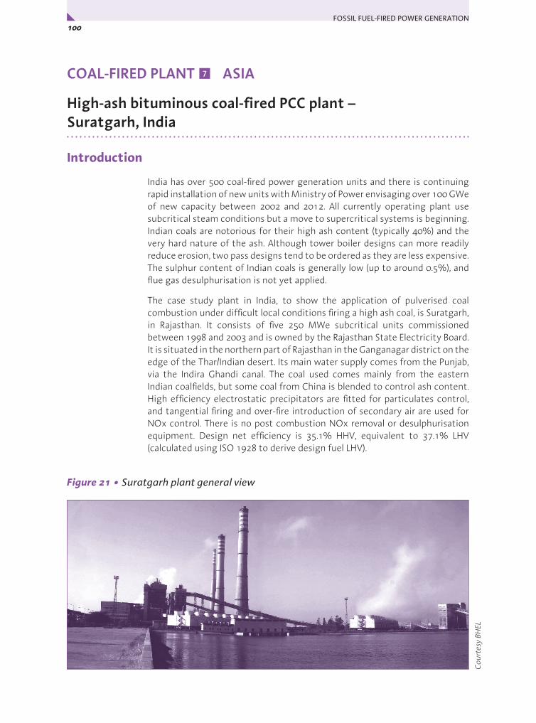
FOSSIL FUEL-FIRED POWER GENERATION 100x
COAL-FIRED PLANT ASIA
High-ash bituminous coal-fired PCC plant – Suratgarh, India
Introduction
India has over 500 coal-fired power generation units and there is continuing rapid installation of new units with Ministry of Power envisaging over 100 GWe of new capacity between 2002 and 2012. All currently operating plant use subcritical steam conditions but a move to supercritical systems is beginning. Indian coals are notorious for their high ash content (typically 40%) and the very hard nature of the ash. Although tower boiler designs can more readily reduce erosion, two pass designs tend to be ordered as they are less expensive. The sulphur content of Indian coals is generally low (up to around 0.5%), and flue gas desulphurisation is not yet applied.
The case study plant in India, to show the application of pulverised coal combustion under difficult local conditions firing a high ash coal, is Suratgarh, in Rajasthan. It consists of five 250 MWe subcritical units commissioned between 1998 and 2003 and is owned by the Rajasthan State Electricity Board. It is situated in the northern part of Rajasthan in the Ganganagar district on the edge of the Thar/Indian desert. Its main water supply comes from the Punjab, via the Indira Ghandi canal. The coal used comes mainly from the eastern Indian coalfields, but some coal from China is blended to control ash content. High efficiency electrostatic precipitators are fitted for particulates control, and tangential firing and over-fire introduction of secondary air are used for NOx control. There is no post combustion NOx removal or desulphurisation equipment. Design net efficiency is 35.1% HHV, equivalent to 37.1% LHV (calculated using ISO 1928 to derive design fuel LHV).
Figure 21 • Suratgarh plant general view
7
Cou
rtes
y BH
EL

101Chapter 3 • Case Studies – Coal-Fired Plant 7: Asia y
The site is more than 1200 km from the main Indian coalfields, and some 800 km from the coast where the Chinese coal is landed. It was built in a relatively remote part of the country to provide a secure supply of power. Many parts of India already suffer from a power shortage. Although power transmission to all states is feasible through the National Grid, a deficit in generation capacity exists and electrical infrastructure is required in remote areas. In order to maximise the security of supply, the decision was made to use several relatively small units at the site and to include the capability to stockpile coal as required.
Table 15 • Summary information on Suratgarh units 1-5
India: Suratgarh, Units 1-5
Owner Rajasthan Utpadan Vidyut Nigam Ltd (RUVNL)
Date of first operation 1998 (unit 1) – 2002 (unit 5)
Boiler supplier Bharat Heavy Electricals Limited
Turbine suppliers Bharat Heavy Electricals Limited
Technology Two-pass subcritical, recirculating
Capacity, MWso 5 x 227
Coal type ~30% ash bituminous blend (indigenous and imported)
Design efficiency (LHV, sent out basis) 35.1% HHV, equivalent to 37.1% LHV*
Type of cooling system Water cooled with forced draught cooling tower
Environmental controls fitted Combustion measures for low NOx; ESP; low sulphur coal
*Calculated from turbine heat rate, boiler efficiency on HHV basis, plant power demand, and calculated design fuel LHV by ISO 1928.
Main challenges met in designing the plant
Although there are now Indian Government requirements to restrict average coal ash levels to no more than 34% at power stations where the fuel has to be transported over long distances, Suratgarh’s units were designed before that restriction applied. They were designed to use high ash content indigenous coals of ash content 45%. The fuel used is now selected to keep to around 30%, but the latter level of ash is nevertheless still high by world standards, and the ash is very high in silica and so abrasive. Designing for Indian coals therefore requires special measures, and the local boiler suppliers (BHEL) are familiar with these. Measures needed include:
y requirement of new coal berth and silos for the site;
y adequate capacity of the coal and ash handling equipment;
y adequate capacity and ruggedness of milling equipment, to ensure availability and for correct pulverised coal particle size for effective burnout;

FOSSIL FUEL-FIRED POWER GENERATION 102x
y provision of particulate separators commensurate with the high flue gas dust loading;
y minimisation of erosion (tower boilers could be more suited, but two-pass systems are usually offered in competitive bids in India because there they have a lower capital cost);
y appropriate heat transfer surface distributions (radiant to convective) in the boiler.
Other particular challenges in designing and building the Suratgarh units were associated with the desert environment and the remote location. Water quality available at the site varies with the season and presented particular design requirements. Scaling of condenser tubes can be a difficulty due to fine dust accumulation. Additional maintenance therefore has to be planned in to avoid blockages. Arrangements were made for collection and de-silting of the rain water in case of interruption of incoming water supplies from the Indira Ghandi canal. A reservoir for storing 21 days’ requirement for the whole power plant had to be provided. The soil at the site consists mainly of fine sand with some silt and is highly permeable. The ground water table is low, and site conditions necessitated the use of substantial foundations for the units.
During the year the ambient air temperature can vary from 50°C to around freezing, and the relative humidity from 12% to 87%. At the time of the site visit (May 2006), the temperature was 49°C. The annual rainfall is about 200-250 mm and, because of the surrounding desert, the atmospheric conditions are dusty, and sandstorms a common occurrence. The plant design, and particularly that of air intakes, needed to take this into account. The local weather conditions can also present other difficulties, for example for electronic control equipment, which can be adversely affected. Storm conditions can also cause wastage of coal.
Overall configurationIn each unit, the coal is burned in a two-pass subcritical boiler supplied by Bharat Heavy Electricals Limited (BHEL). NOx from the furnace is minimised by the use of combustion measures. After the boiler, electrostatic precipitators remove dust from the flue gases before they reach the stack.
The natural circulation boiler converts water to subcritical steam. The steam is expanded in a turbine supplied by BHEL, reheated in the boiler, then expanded again, before being condensed and returned as water to the boiler. Steam parameters are 15.8 MPa/540°C/540°C. The condenser is cooled with water, which here allows a condenser pressure of 10.5 kPa at the design conditions.
The coals currently received include unwashed and washed indigenous coals plus some imported coal to reduce the ash content. The quantity and quality of coals are managed in such a way as to achieve annual average ash percentage around 30%. At the time of the visit, the overall coal mix being used would result in a coal feed with an average ash content just below 34%, but there will be considerable variations from boiler to boiler as there is no formalised blending method. The range of the LHV as fired was 16-17.6 MJ/kg. Coal quality issues are discussed further in the Commentary section.

103Chapter 3 • Case Studies – Coal-Fired Plant 7: Asia y
Table 16 • Selected performance-related information on Suratgarh (Unit 5)
Annual operating efficiency (LHV, sent out basis) 35.4% HHV gross generated all unit average equiv. to 32.1% net HHV basis (estimated 33.9% net, LHV*)
Fuel calorific value (a.r.), MJ/kg LHV and HHV 16-17.6 LHV in mixture used (14.7 HHV design)
Fuel ash content (a.r.), % 45 design; ~30 actual
Fuel moisture content (a.r.), % 10 design
Fuel sulphur content (a.r.), % 0.5 design
Gross power output, MWe, at MCR 250
Net power output, MWso, at MCR 227
Auxiliary power consumption, MWe at MCR 22.8 average 2005-2006
Main boiler feed pump drive (motor or turbine) Variable speed electric
Steam conditions 15.6 MPa/540°C/540°C at boiler
Feedwater heating stages 3 LP + deaerator + 2 HP
Final feedwater temperature, °C 246
Type of cooling system, water temperature, °C Water, forced draught cooling tower, 27°C inlet typical
Condenser pressure, kPa 10.5
NOx abatement systems Combustion measures
NOx emissions, 6% O2, dry design 159 g/s; value in mg/m3 not available
Desulphurisation system -
SO2 emissions, 6% O2, dry design 230 g/s; value in mg/m3 not available
Particulates removal system ESP
Particulates emissions, 6% O2, dry 50 mg/m3 achieved
Specific capital cost, USD/kWso 822 (2002) basis uncertain
*Calculated from HHV operating efficiency by factoring in same ratio as design LHV efficiency/design HHV efficiency (shown in Table 15).
Plant description
The plant consists of five, virtually identical, 250 MWe outdoor boilers with associated turbogenerators, all supplied by BHEL. The units are arranged in a row, with three stacks. One stack serves units 1 and 2 and a second stack serves units 3 and 4. A third stack serves unit 5.
Coal handling and preparation
The coal is delivered by rail and unloaded from Bogie Open Bottom Release (BOBR) railway wagons on to separate piles. A limited degree of blending is carried out using bulldozers around the stockpiles. Coal is carried in bulldozer
FOSSIL FUEL-FIRED POWER GENERATION 104x
buckets and dropped into the main reclaim hoppers. Underneath these are various vibrator trays which even the flow so that it totals about 700-800 t/h to feed all the boilers. Coal supply to the boiler bunkers is managed remotely from a central control room.
The average ash content of the coals used is below 34%. Data from 2005/06 indicate that just over 6 Mt of coal was used, producing some 1.74 Mt of ash, indicating an average ash content of some 28.5%. The boilers are designed to accept coal at up to 45-50% ash content, and in the absence of formal blending, the feed to some of the boilers may be as high as this.
The coal is pulverised using double-ended ball (tube) mills. These were selected on the basis of the hardness and variability of the coal to be used. Although tube mills have higher power consumption than vertical spindle mills, they have lower maintenance costs on these coals. Tube mills are very rugged and all required maintenance can be carried out during planned plant shutdowns. Consequently, each boiler-turbine unit has been designed to use two mills operating with one spare on worst coal. At full output, each mill handles 80 t/h of coal. The air temperature at the mill inlet is 227°C. One double-ended mill can supply two burner rows.
Boiler combustion system
On each boiler, pulverised coal is conveyed by heated and tempered primary air from the mills to the 24 low-NOx burners on the boiler. These are tilting tangential burners mounted in the corners of the boiler furnace to reduce the formation of NOx by giving a recirculating fireball The use of over-fire air above the upper burners is also being trialled on one of the units. With good control of the air to the primary burners and of the over-fire air, NOx formation is reduced by about 40-50% compared with uncontrolled combustion. At different loads, the angle of tilt of the burners is varied to achieve high burnout and low emissions and to control steam temperatures.
Boiler heat transfer surfaces
The evaporator tubing is welded to form the membrane wall of the boiler. The furnace wall tubes in this recirculating boiler are arranged vertically. The economiser heating surfaces are located within the boiler flue gas path near to the exit of the boiler rear convective pass. The boiler is a natural circulation type with steam drum. Water from the economiser is fed to the drum, which operates at 16.7 MPa. Water flows from the drum down to the evaporator tubing and is partly converted to saturated steam. The water/steam mixture flows back to the steam drum by natural convection. The saturated steam is separated from the water in the drum for passing on to the superheaters, and the water recirculates to the evaporator.
The superheater is arranged in the usual three stages: primary, secondary and final, with conventional systems for temperature control by spray water attemperation between them. The primary superheater is located in the rear pass, above the economiser. The platen type secondary superheater and the

105Chapter 3 • Case Studies – Coal-Fired Plant 7: Asia y
final superheater sections are at the top of the boiler around the beginning of the convective pass. The reheater is located between them, downstream of the platen superheater. Figure 26 shows the general arrangement of heat extraction surfaces in the boiler of unit 5.
Reheat steam temperature is controlled by adjusting the tilt of the boiler burners and by control of excess combustion air flow. Spray type attemperators are available for emergency use. Superheater outlet conditions are 540°C at 15.6 MPa, and reheat conditions 540°C at 3.7 MPa. The boiler design efficiency is 87.78% on an HHV basis.
Draught system
The boiler of each unit operates using the conventional balanced draught system. Here, there are two forced draught and three primary air fans supplying combustion air and three induced draught fans drawing the flue gases from the boiler through the electrostatic precipitators.
The primary and secondary combustion air flows of each unit are preheated using two parallel tri-sector rotary Ljungstrom regenerative airheaters that
extract heat from the combustion gases after they leave the economiser. The preheated primary air, after tempering with unheated primary air, dries and conveys the pulverised coal from the mills to the burners on the boiler. The preheated secondary air is admitted to the furnace as over-fire air to provide air staging. The design temperature of the flue gas at the outlet to the air heater is 140°C.
The flue gas leaving the airheaters passes to electrostatic precipitators for particulate removal. The flue gas outflows from the precipitators go to the induced draught fans, which send the gases to the stack.
Emission control equipment
NOx control
For NOx control and reduction, the combustion measures referred to earlier are used. Critical to optimum operation of such fuel and air staging systems
Cou
rtes
y BH
EL
Figure 22 • Suratgarh – general arrangement of heat extraction surfaces in boiler (unit 5)
FOSSIL FUEL-FIRED POWER GENERATION 106x
is the quantity of excess air that is used in firing the coal. Consequently, the oxygen in the flue gases before the air pre-heater is monitored, and the amount of excess air is controlled using this to achieve maximum carbon burnout with minimum NOx production. Two over-fire air nozzles are provided at the top of the wind box. Design NOx emission rate is 159 g/s per unit. Information could not be obtained in alternative units.
SO2 control systems
There is no requirement to remove SO2 from the flue gases. The coal used is low in sulphur content.
Particulate control system
Each 250 MW plant is provided with two electrostatic precipitators (ESPs). The ESPs were designed to meet the particulate emission value of less than 100 mg/m3 with one field out of service under boiler maximum continuous rating operating conditions. The fly ash from Indian coals is difficult to catch because of its high electrical resistivity. The high inlet dust loading and high required ash collection efficiency necessitated the use of seven electrical fields (collection zones) in series and pulse energisation to achieve high performance. Particulate collection efficiency is 99.886%.
The 220 m stack has instrumentation to monitor the gases for opacity, SO2 and NOx. Data collected during 2005-2006 show that all the units kept well within the design 100 mg/m3 for suspended solids, with average emissions from unit 5 the lowest, at 50 mg/m3.
Ash utilisation
Furnace (bottom) ash that is collected is ground and slurried, then conveyed to ash dykes by slurry pumps. It is also used for road building. Much of the fly ash is conveyed by a vacuum conveying system to silos for storage, prior to being supplied to the cement and brick industries and for embankment/land filling. The remaining fly ash is slurried then conveyed to ash dykes through slurry disposal lines.
Total ash utilisation has grown steadily. It was initially very low, as it was necessary to build relationships with possible users. Between 2003 and 2005, utilisation climbed to just over 20%. In 2005/06 it increased to nearly 50% (of an increased quantity), and there is a requirement that by 2010 all the ash should be utilised. Suratgarh is on course towards achieving this objective. The ash is provided free of cost to users.
Steam turbine and water/steam system
The steam and water cycle is a conventional single reheat condensing subcritical system. The 3000 rpm 250 MWe tandem compound steam turbine generators were supplied by BHEL, who maintain a technical collaboration with Siemens. Each 50% reaction turbine consists of one single flow high-pressure turbine, one single flow intermediate pressure turbine and one

107Chapter 3 • Case Studies – Coal-Fired Plant 7: Asia y
double flow low pressure turbine. The turbine is equipped for extraction of steam for feedwater heating. Main steam conditions are 15.8 MPa/540°C/540°C. Turndown is achieved by throttling but output is generally at close to nominal rating.
The low pressure turbine has a water cooled condenser mounted beneath it where the wet steam emerging from the turbine (at 10.5 kPa under design conditions) is fully condensed to water. In practice, the turbine exit pressure will vary considerably in this difficult location, depending on the cooling water inlet temperature, and this will affect plant thermal efficiency.
The cooling water system is a recirculating system with cooling towers. Make-up water comes from the Indira Ghandi canal. The maximum loss of water through evaporation when the ambient air temperature is 50°C is 600 t/h. Typical condenser conditions, with ambient air at 40°C, are a water inlet temperature of 27°C. The temperature rise across the condenser is typically 11°C, which equates to a cooling water outlet temperature of 38°C. This allows a sufficient temperature pinch relative to the condensing steam for the design turbine exhaust pressure to be met, but in this desert location, temperatures close to 50°C are not uncommon, so reducing efficiency. The cooling towers are forced draught mechanical units.
Feedwater heating
The feedwater heating circuit has six stages of feedwater heating: three low pressure (LP) heaters, a deaerator combined with storage tank, and two high pressure (HP) heaters. Final feedwater temperature is 246°C. The low pressure heaters are shell and tube heat type, and the high pressure heaters are of U-tube type. An electrically driven boiler feed pump is used to pump the feedwater from the storage tank to the economiser. The boiler feedwater pump delivery pressure is 18 MPa.
Economics
The plant specific capital cost was around 4 Crore Rupees/MWso in 2002 (822 US$D/kWso in 2002). This is an approximate figure and the basis is uncertain. Construction time for a unit is 39 months. The plant was established on a greenfield site. There are 80 operating staff for each unit, working in 4 shifts (20 per shift).
The coal cost is understood to be higher than normal for India because of the distance from the coalfield and the requirement to use coal with an ash content below 34% - although this brings possible operational advantages. Some operational costs such as those for staffing will be slightly higher than those for plants which are in a less remote location.
The plant load factor (PLF) has risen from just under 75% in the period 1998-2000 when the first units were being commissioned to nearly 91% during the year 2005-06, paralleled by a growth in availability from 79.2% in 1998-99 to 92.5% in 2005-06. These levels indicate good economic performance.

FOSSIL FUEL-FIRED POWER GENERATION 108x
Auxiliary power consumption has dropped from about 10.5% in 1998 to an average of 9.25% (23 MWe per unit) from 2000 onwards. The specific oil consumption for supporting and initiating combustion has been decreased to a low level of 0.6 ml/kWh in 2005-2006. This shows that the units have been operating well on the coal blends used. Both these indicators also suggest improving economic performance.
Commentary
This plant has shown that plants can be designed to suit a difficult desert environment, where water quality is variable. The thermal efficiency is inevitably penalised by the conditions, but future, higher efficiency supercritical units will be able to build on the experience here.
Although there are now Indian Government requirements to restrict average coal ash levels to 34% at most power stations, this is still high by world standards, and the ash is very high in silica. Efficient and economic use of these fuels is best served by reducing the ash content in some way before firing. It is also best to reduce the ash content before transportation to reduce the cost of transport per GJ and keeps more of the mineral matter near to the mines. However, there is a difficulty in moving below 30% if indigenous coals are to remain the main fuel, as seems sensible, because a high proportion of the ash is finely distributed within the coal material and so hard to remove. So the need to be able to fire coals of about 30% ash in India seems likely for some time.
At Suratgarh, they have included some lower ash (12%) coal from China to help keep within requirements. At the time of the visit (May 2006), the overall coal mix being used was:
y provision of particulate separators commensurate with the high flue gas dust loading;
y 40% of a low ash coal from the Korba area of South Eastern Coalfields Ltd. from thin seams of superior quality coal, comprising grades B to D mined underground, ash content 27%;
y 10% of low ash coal imported from China with an ash content of 12%;
y 20% of a washed Indian coal, F grade, with an ash content of 30% (washed Korba coal from Dipika washery); and
y 30% of raw Indian coal with an ash content of 40%.
The indigenous coal has an LHV averaging about 17 MJ/kg, while the imported coal has an LHV of some 28 MJ/kg. The range of the LHV of the mix was 16-17.6 MJ/kg. The coal HGI varies from 45 to 55, with an average of 50.
Future plans
India has a very large number of coal-fired power generation plants, and almost 70% of electric power is produced using coal. All currently operating plant use subcritical steam conditions but a move to supercritical has begun.
109Chapter 3 • Case Studies – Coal-Fired Plant 7: Asia y
A supercritical station, at Sipat (3 x 660 MWe), is being manufactured by suppliers from Korea (Doosan Heavy Industries & Construction Co.) and Russia and due to be completed early in 2009. There are also plans for a further 20 GWe of supercritical capacity, and BHEL has associated with Alstom, in order to bid for future plants of 660, 800 or 1000 MWe. The company also has associations with Siemens for the supply of turbines, including supercritical turbines, with advanced blading profiles.
The Indian government has received expressions of interest from 35 domestic and international companies to build four major thermal power projects, each with a capacity of 4,000 MW. The first four plants will be at Madhya Pradesh, Gujarat, Maharashtra and Karnataka. Another two will follow, in Orissa and Andhra Pradesh. The Government intends to extend tax breaks and to ensure adequate supplies of coal.
BHEL is also developing an air blown pressurised fluidised bed gasification based IGCC system, which is referred to in section IGCC Technology Review.
Activities such as those above demonstrate the commitment in India to concentrate in the short to medium term on a policy of limiting greenhouse gas emissions through enhancing the thermal efficiency of coal-fired power generation by using advanced clean coal technologies. In the longer term, once more efficient plants are established, carbon dioxide capture and storage is seen as a possible strategy to adopt together with novel plant designs. This is illustrated by India’s membership of the Carbon Sequestration Leadership Forum and participation in the FutureGen initiative to produce electricity and hydrogen with carbon dioxide and storage.
Acknowledgements
Gordon Couch, Senior Author and Consultant, IEA CCC, for making the plant visit, liaising with the manufacturers and owners and preparing the first draft of this section.
P Selvakumaran, BHEL, India, for supplying plant data.
Suratgarh management and engineers for supplying data.
Background sources
Chikkatur A P, Sagar A D, Towards a better technology policy for coal-based power in India. Available from: http://bcsia.ksg.harvard.edu/BCSIA_content/documents/Chikkatur_Sagar_AER2006.pdf (accessed April 2007).
Ministry of Power, Blueprint for Power Sector Development, Ministry of Power, Government of India, Available from: http://powermin.nic.in/ (accessed April 2007).
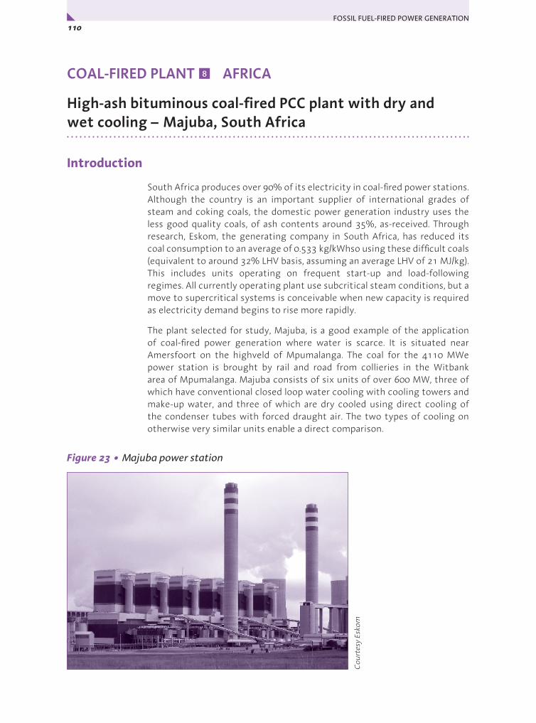
FOSSIL FUEL-FIRED POWER GENERATION 110x
COAL-FIRED PLANT AFRICA
High-ash bituminous coal-fired PCC plant with dry and wet cooling – Majuba, South Africa
Introduction
South Africa produces over 90% of its electricity in coal-fired power stations. Although the country is an important supplier of international grades of steam and coking coals, the domestic power generation industry uses the less good quality coals, of ash contents around 35%, as-received. Through research, Eskom, the generating company in South Africa, has reduced its coal consumption to an average of 0.533 kg/kWhso using these difficult coals (equivalent to around 32% LHV basis, assuming an average LHV of 21 MJ/kg). This includes units operating on frequent start-up and load-following regimes. All currently operating plant use subcritical steam conditions, but a move to supercritical systems is conceivable when new capacity is required as electricity demand begins to rise more rapidly.
The plant selected for study, Majuba, is a good example of the application of coal-fired power generation where water is scarce. It is situated near Amersfoort on the highveld of Mpumalanga. The coal for the 4110 MWe power station is brought by rail and road from collieries in the Witbank area of Mpumalanga. Majuba consists of six units of over 600 MW, three of which have conventional closed loop water cooling with cooling towers and make-up water, and three of which are dry cooled using direct cooling of the condenser tubes with forced draught air. The two types of cooling on otherwise very similar units enable a direct comparison.
Figure 23 • Majuba power station
8
Cou
rtes
y Es
kom
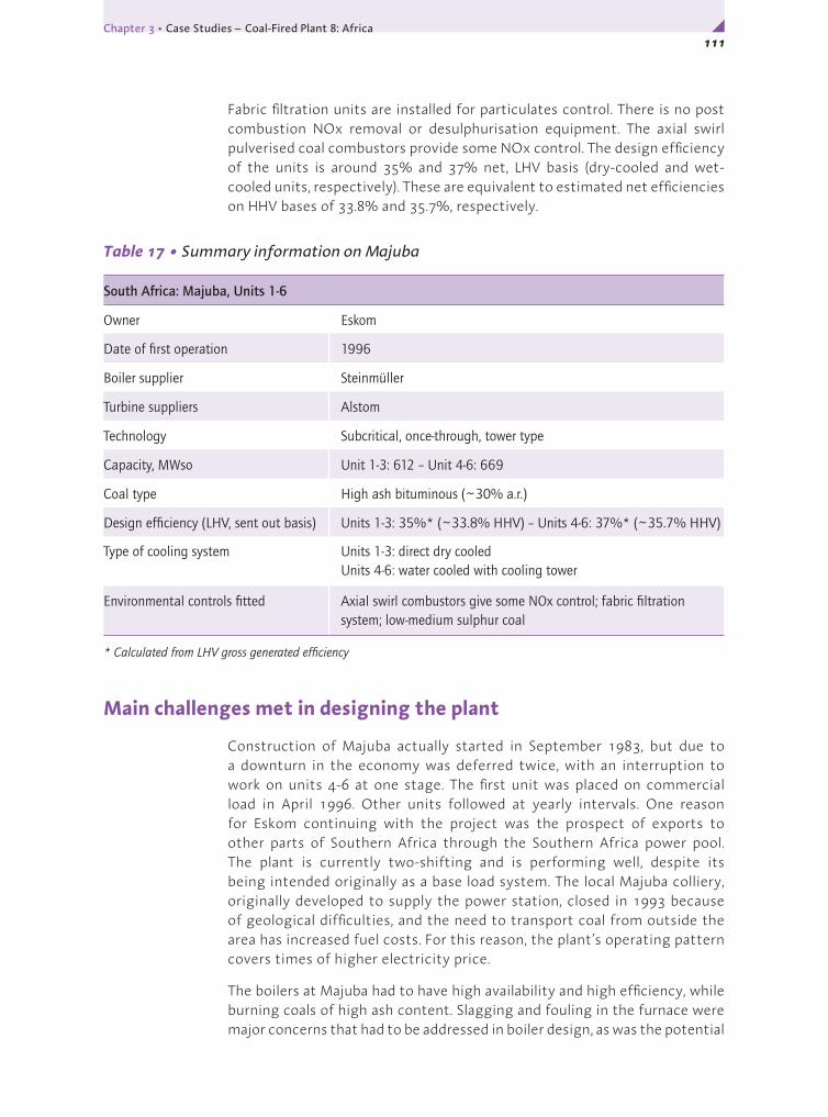
111Chapter 3 • Case Studies – Coal-Fired Plant 8: Africa y
Fabric filtration units are installed for particulates control. There is no post combustion NOx removal or desulphurisation equipment. The axial swirl pulverised coal combustors provide some NOx control. The design efficiency of the units is around 35% and 37% net, LHV basis (dry-cooled and wet-cooled units, respectively). These are equivalent to estimated net efficiencies on HHV bases of 33.8% and 35.7%, respectively.
Table 17 • Summary information on Majuba
South Africa: Majuba, Units 1-6
Owner Eskom
Date of first operation 1996
Boiler supplier Steinmüller
Turbine suppliers Alstom
Technology Subcritical, once-through, tower type
Capacity, MWso Unit 1-3: 612 – Unit 4-6: 669
Coal type High ash bituminous (~30% a.r.)
Design efficiency (LHV, sent out basis) Units 1-3: 35%* (~33.8% HHV) – Units 4-6: 37%* (~35.7% HHV)
Type of cooling system Units 1-3: direct dry cooled Units 4-6: water cooled with cooling tower
Environmental controls fitted Axial swirl combustors give some NOx control; fabric filtration system; low-medium sulphur coal
* Calculated from LHV gross generated efficiency
Main challenges met in designing the plant
Construction of Majuba actually started in September 1983, but due to a downturn in the economy was deferred twice, with an interruption to work on units 4-6 at one stage. The first unit was placed on commercial load in April 1996. Other units followed at yearly intervals. One reason for Eskom continuing with the project was the prospect of exports to other parts of Southern Africa through the Southern Africa power pool. The plant is currently two-shifting and is performing well, despite its being intended originally as a base load system. The local Majuba colliery, originally developed to supply the power station, closed in 1993 because of geological difficulties, and the need to transport coal from outside the area has increased fuel costs. For this reason, the plant’s operating pattern covers times of higher electricity price.
The boilers at Majuba had to have high availability and high efficiency, while burning coals of high ash content. Slagging and fouling in the furnace were major concerns that had to be addressed in boiler design, as was the potential
FOSSIL FUEL-FIRED POWER GENERATION 112x
for high rates of erosion of boiler components. A three-burner staggered formation was chosen to minimise slagging. The tower boiler design was adopted to simplify arrangement of wall panels and pipework to avoid stress and to give a uniform flue gas flow pattern to help reduce tube erosion.
Majuba’s first three units use direct air cooled condensers, while the others use conventional wet cooling. The local water supply situation at the time of selection of the cooling systems for units 1 to 3 was poor and so dry cooling was chosen because it uses only 20% of the net quantity of water that wet cooling consumes. This was necessary despite the greater capital cost of such systems. Wet cooling was however selected for the later units after economic assessments at that time showed that it would be more viable.
Overall configuration
The overall configuration is as follows. In each unit, the high ash (~30%) coal is burned in a subcritical once-through tower boiler supplied by Steinmüller. After the boiler, a fabric filtration unit remove dust from the flue gases before they reach the stack.
The once-through boiler converts water to subcritical steam. The steam is expanded in a turbine supplied by Alstom, reheated in the boiler, then expanded again, before being condensed and returned as water to the boiler. Steam parameters at the boiler exit are 17.2 MPa/540°C/540°C. The condensers of units 1-3 are direct dry cooled by air. The condensers of units 4-6 are cooled with water. Condenser pressures of the dry and wet systems are 16.6 kPa and 6 kPa, respectively, at design conditions.
The coals currently received are mainly from the Ermelo/Witbank coalfield.
Plant description
The following applies to each unit except where indicated.
Coal handling and preparation
The coal is brought by rail (40%) and road (60%) from a distance of around 300 km. The supply consists of a mixture of opencast (surface mined) and deep mined product and colliery discard from eleven suppliers, mainly in the Ermelo/Witbank coalfield. The coal delivered to the power station has a nominal calorific value of 21.5 MJ/kg and an ash content of around 35%. Coal crushed to less than 50 mm in size is conveyed from the reception bunkers at a rate of up to 4200 t/h. The maximum strategic and seasonal stockpiles total 6000 kt. From the stockpile, coal is transported by terrace conveyors to silos, each of 10 000 t capacity. Inclined conveyor belts carry the coal from the silos to each of the five 800 t capacity boiler mill bunkers – sufficient for eight hours’ operation at full load.

113Chapter 3 • Case Studies – Coal-Fired Plant 8: Africa y
Table 18 • Selected performance-related information on Majuba
Annual operating efficiency (LHV, sent out basis) 34% (note: two-shifting) (~32.8% HHV basis)
Fuel calorific value (a.r.), MJ/kg LHV and HHV 21 (19-24.8) (~21.8 HHV)
Fuel ash content (a.r.), % 31.2 (18.6-39.8)
Fuel moisture content (a.r.), % 3.1 (1.7-4.4)
Fuel sulphur content (a.r.), % 0.81 (0.7-1.7)
Gross power output, MWe, at MCR Units 1-3: 657 – Units 4-6: 713
Net power output, MWso, at MCR Units 1-3: 612 – Units 4-6: 669
Auxiliary power consumption, MWe at MCR Units 1-3: 45 – Units 4-6: 44
Main boiler feed pump drive (motor or turbine) Motor
Steam conditions 17.2 MPa/540°C/540°C at boiler
Feedwater heating stages 3 LP + deaerator + 2 HP
Final feedwater temperature, °C 248
Type of cooling system, water temperature, °C Units 1-3: direct dry Units 4-6: wet, cooling tower; condenser inlet 22°C
Condenser pressure, kPa Units 1-3: 16.6 kPa – Units 4-6: 6 kPa
NOx abatement systems Axial swirl combustors
NOx emissions, 6% O2, dry 600 mg/m3
Desulphurisation system -
SO2 emissions, 6% O2, dry ND
Particulates removal system Fabric filtration
Particulates emissions, 6% O2, dry 50 mg/m3
Specific capital cost, USD/kWso ~410 (2001) including IDC and owner’s costs
The coal is pulverised using horizontal ball (tube type) mills. Two control feeders channel the coal from each bunker into an 80 t/h rotating double-ended mill. Mill reserve capacity is such that an additional 20 t/h output can be achieved from each. The mills have a double cone classifier on each outflow to separate coarser material to return it to the mill. Preheated primary combustion air is used to simultaneously dry and convey the mill output to the boiler burners. There is a total of thirty burners, and each of the five mills connects with six of them. Normally four mills are operating for unit rated output, with one spare, and full load is achieved using twenty-four burners. The coal is relatively difficult to grind and tube mills provide ruggedness.
Although generally not containing high moisture levels, the coals used can be rather high in fines, giving handling difficulties such as blocked chutes and bunker bridging.

FOSSIL FUEL-FIRED POWER GENERATION 114x
Boiler combustion system
Pulverised coal is conveyed by heated and tempered primary air from the mills to the axial swirl burners which surround the incoming coal with a curtain of swirling secondary air for control of NOx production. The burners are mounted in five staggered levels on the boiler front and rear walls (opposed firing). Normally, only 24 of the 30 burners are used to achieve full output. Oil firing (introduced through a central tube in each burner) is used for start up and for flame stabilisation at low loads. The staggered arrangement was used to minimise slagging.
The coal combustion produces coarse ash and fly ash in a ratio of approximately 1:10. The coarse ash drops to the bottom of the boiler and is conveyed away for disposal. The fly ash is carried in the flue gases to the fabric filter where more than 99% of it is removed.
Boiler heat transfer surfaces
The once-through subcritical boiler on each unit provides superheated and reheated steam in a single pass. The evaporator tubing, welded to form the membrane wall of the boiler, is in spiral formation in the lower part of the boiler, to aid uniform heat absorption, and vertically arranged in the upper sections where it is further from the most intense heat release area. The boiler is suspended from the top, as is normal, to allow for expansion on heat-up.
Boiler feedwater is heated to a temperature of 248°C before being fed to the economiser. From the economiser the water passes to the membrane wall evaporator, where evaporation occurs completely. The resulting steam is collected in four steam separators for sending on to the primary superheater. Under start-up conditions, the separating vessels return water for evaporation but there is no recirculation under normal running conditions and no steam drum.
Superheater and reheater tube banks are suspended horizontally above the furnace zone of this tower-type boiler, and the economiser elements are located at the top. The superheater is arranged in the usual three stages: primary, secondary and final, with conventional systems for temperature control by spray water addition (attemperation) between them. There is also an attemperation system for the steam flow from the evaporator. Reheat steam temperature is controlled by spray attemperation between its two stages.
Superheater outlet conditions are 540°C at 17.2 MPa, and reheat conditions are 540°C at 3.9 MPa. The boiler design efficiencies are 90.3% (units 1-3) and 91.3% (units 4-6)% on an LHV basis, but recent tests show performance to be at least one percentage point better than those values. Sliding pressure operation is available for turndown (to 55% MCR) to keep efficiency high. Loading ramping rate is 15 MWe/min.
Draught system
The boiler of each unit operates in balanced draught and has two parallel combustion air and two parallel flue gas systems. Each combustion air
115Chapter 3 • Case Studies – Coal-Fired Plant 8: Africa y
system has one forced draught (FD) fan, one secondary steam air heater, one regenerative air heater, one primary air (PA) fan, one primary steam air heater and one shell and tube type primary air heater. Shell and tube air heaters were selected for heating the primary air because of their total gas tightness, as a relatively high primary air pressure is used to transport the pulverised fuel into the furnace. Tubular primary air heaters were also selected for primary air heating at two of Eskom’s other power plants. Each flue gas system has a fabric filtration unit and one induced draught (ID) fan.
The FD fan draws in air either from the top of the boiler-house or through the secondary steam air heater. The air is delivered to the PA fan and directly to the burners via the regenerative air heaters. The PA fan delivers hot (from the PA heaters) and cool air streams and the mixed air streams dry and convey the pulverised coal.
The design temperature of the flue gas at the outlets to the tubular and regenerative air heaters is around 130°C.
Emission control equipment
NOx control
There are no post combustion flue gas NOx control systems on the plant. The axial swirl combustors are designed to give control of NOx emissions to 600 mg/m3 at the stack
SO2 control
There is no requirement to remove SO2 from the flue gases. The coals used have an average sulphur content of 0.8%, as received.
Particulate control and ash disposal
During the period of deferment of construction of Majuba referred to earlier, Eskom reviewed its environmental policies, and determined that particulate emission limits for new or refurbished units would be reduced to 50 mg/m3. The original particulate control system was to use ESPs, but it was found that there was insufficient space and it would not be economically viable to increase their size to meet the new specification. A reverse pulse jet fabric filtration (PJFF) system was therefore substituted as it was more viable and could be accommodated within the original ESP footprint.
Each unit is served by two PJFF units (the world’s largest), one situated in each of the twin flue gas paths after the air heaters. Flue gas is drawn by the ID fan, placed after the filter plant, where the fly ash is removed from the gas before it is discharged via the stack. The pressure drop across the fabric filtration plant (at 1.5 kPa,), is approximately 10 times as high as that for an electrostatic precipitator, so a two-stage ID fan is used. The fly ash that is removed from the gas is collected in the hoppers at the base of the filter assembly then transported to ash silos via a pneumatic conveying system.
FOSSIL FUEL-FIRED POWER GENERATION 116x
At full load, each boiler produces up to 240 tons of coarse ash and 2 400 tons of fly ash. The fly ash is conditioned to a moist cake before being mixed with the coarse ash. The mixed ash is fed to an overland conveyer system, which transports it to surface disposal. Trucks and dozers spread the ash over the disposal site, which will eventually be covered with a 200 mm layer of topsoil and then grassed.
Steam turbine and water/steam system
The steam and water cycles are slightly different for units 1-3 as compared with units 4-6 because different types of cooling system are used (dry and wet), which result in different condenser temperatures and pressures and so different turbine exhaust conditions. Each of Majuba’s six 3000 rpm condensing steam turbines has a high-pressure cylinder, a double-flow intermediate-pressure cylinder and two double-flow low-pressure cylinders. The HP cylinder is a conventional single flow system. Both HP and IP cylinders are constructed with an internal and external casing to allow fast starting and rapid variations in load. The turbine is equipped for extraction of steam for feedwater heating. Main steam conditions at the turbine inlets are 16.1 MPa/ 535°C/535°C. Turndown (to 55% MCR) is achieved by sliding pressure.
Each of the LP cylinders has 4 stages per flow section for the higher backpressure units (1 to 3), while those of lower exhaust pressure on the three water cooled units (4 to 6) have five stages per flow.
Feedwater heating
Although the condensate temperature is different in the dry and water cooled units, the feedwater heating circuits are very similar. All have three low pressure (LP) heaters, a deaerator combined with storage tank, and two high pressure (HP) heaters. Water from the condensers (direct dry-cooled and wet cooled systems) is pumped by the condensate pumps through the low-pressure heaters to the deaerator and condensate storage tank. Two 50% electrically driven variable-speed boiler feed pumps are used to pump the feedwater from the storage tank through the high-pressure heaters to the economiser. A third pump is provided as a stand-by in the event of failure. Final feedwater temperature is 248°C.
Cooling systems
There are two types of cooling system at the Majuba site. Units 1-3 use direct dry cooling, and units 4-6 use conventional water cooling in a recirculating system with natural draught cooling towers (one 153 m tower per unit).
y Units 1-3 – direct dry-cooling system
These systems use direct air cooling of the steam exhausting from the low pressure turbine in large ‘A’-frame-shaped condensers containing externally finned tubes. The steam is passed through the tubes (in contrast to the familiar water cooled systems that are of shell and tube design, with steam passing over the surface of the water cooled tubing). Because they have to

117Chapter 3 • Case Studies – Coal-Fired Plant 8: Africa y
allow a large air flow over a very large area of finned tubing, direct air-cooled condensers are too large to be integrated with the turbine, so they are located adjacent to the turbine house. The steam condenses to water in the finned tubes. There is approximately 496 km of parallel finned tubing to each condenser unit, and wide ducting (two interconnected, 5 m diameter) is used to connect the turbine to the condenser to minimise back-pressure.
Each condenser unit comprises eight rows of six modules each, of which five are condenser modules and one is a dephlegmator module. While the purpose of the condenser modules is solely to condense the steam, the dephlegmator module also provides for the extraction of incondensable gases and air. The condensate is collected in a receiver tank outside the turbine house.
Heat from the steam circuit is removed by air blown over the condenser tubing by the forty-eight 9.1 m diameter forced-draught fans beneath each module. The condensing capability and pressure of such condenser systems is very dependent on the ambient (dry-bulb) temperature, so unit output and efficiency vary with season. Condenser conditions are 16.6 kPa for these dry-cooled units at design conditions (20°C). Ambient temperature range is -8°C to 34°C. Data from the plant operators showed gross power capability varying typically between 620 MWe and a design 657 MWe, from a backpressure range of 41.5 kPa-13.4 kPa.
Fan power could be expected to be high, but is not necessarily more than that of the cooling water pumping systems in conventional wet units. The power consumptions of the two types of unit at Majuba are in fact very similar, (see later). The higher turbine exhaust pressure does however result in efficiency, gross or net, being around two percentage points lower than for the wet-cooled units.
y Units 4-6 – conventional wet cooling system
Units 4-6 of Majuba utilise the conventional wet-cooling technology with condensers mounted beneath the low pressure turbines and circulating water extracting the heat for rejection through natural draught cooling towers. Steam emerging from the turbine passes down to the shell (chamber) portion of the shell and tube condensers, in which the cooling water for condensing the steam flows through the tubing.
There is a large requirement for make-up cooling water to compensate for the evaporation rate (over 1000 t/h at design point). The cooling towers take recirculated water in at 33.4°C and return it to the condensers at 21.7 °C at design conditions. Condenser pressure is 6 kPa, design. Output and efficiency of units 4 to 6 typically vary far less than those of the air-cooled units (in this case 704 MWe to 713 MWe, gross generated, from a backpressure range of 8.4 kPa to 3.2 kPa).
There are six circulating water pumps, and they consume 44 MWe, compared with the 45 MWe consumed by the fans on the air-cooled units. Wet cooling was selected for the later units based on economic evaluations, but dry cooling would be considered for future units in the country, depending on water availability.

FOSSIL FUEL-FIRED POWER GENERATION 118x
Plant control system
Changes in technology over the plant’s long construction period mean that instrumentation and control for units 4 to 6 are more advanced than those for units one to three. The first three of Majuba’s six boiler turbine sets are operated from separate unit control rooms, and units 4 to 6 are controlled from a common control room. Plants can be automatically started up and shut down from a keyboard in the unit control desk. Manual control of the plant can also be carried out via push-button stations. Any part of the process and plant conditions can be graphically displayed on video screens. New burner control equipment was installed in 2004 to monitor and optimise performance of the burners in order to reduce maintenance costs.
Economics
The specific capital cost of the station was approximately 410 USD/kWso upon completion in 2001. This included interest during construction and owner’s costs and is extremely low. The plant was established at a greenfield site. There is a total of 550 operating staff at the six units.
Majuba has been two-shifting with load following in recent years. The approximate capacity factor was 32% for the dry-cooled units over the last 3 years (estimated from average production shown on Eskom’s website in 2006) because of the high delivered fuel costs mentioned earlier. Expected starts for the current year will be around 800 - 1000. Availability is good: Eskom cite a recent figure of 97.2% for the dry-cooled units.
Commentary
Majuba is a good example of the application of coal-fired power generation where water is scarce. Different cooling systems (dry and wet) were installed so this has enabled a comparison of the systems. Water cooling for the later three units was selected on the basis of economic evaluations, including the cost of provision of additional water for the site and the benefit of greater output.
The investment and operating costs of dry-cooled systems are in any case rather high because of their more complex design around the LP turbine end and the lower efficiency and output because of the high exhaust pressure. Consequently, the physical constraint of limited water availability determines the selection of dry cooling. The economics alone will seldom point to dry cooling.
The boilers at Majuba have shown that high ash coals of difficult slagging and fouling propensity can be burnt in pulverised coal systems when suitably designed. Here, a staggered burner arrangement was used to minimise slagging and excessive erosion has been avoided by adopting a tower boiler. Although tower designs tend to be more expensive than two-pass boilers, the investment cost was by no means high by world standards. Tower boiler

119Chapter 3 • Case Studies – Coal-Fired Plant 8: Africa y
systems also enable other potential maintenance issues, such as stresses on pipework to be reduced. The plant is currently two-shifting because coal supplies are relatively expensive due to long haulage distances. However, it has good availability, despite being intended originally as a base load system.
Majuba was not designed to have very low NOx emissions and it has no desulphurisation equipment, but legislation did not demand it. Future legislation on emissions limits from new plants in South Africa will probably mean that some specific measures will be needed. A revised air quality act from the government is awaited, regarding requirements on future SO2, NOx and particulates emissions limits. Particulate emissions limits have been set at 50 mg/m3. Limits for SO2 and NOx emissions are expected to be set by September 2007, but they are unlikely to be as low as the new EU limits.
Eskom is currently exploring the possibility of underground coal gasification as a supplemental energy source for Majuba. Eskom is committed to the use of coal as the mainstay of power generation for South Africa and is refurbishing some older units and has plans for some new build. Eskom is understood to be currently in the bidding stage for 3x660 MW supercritical power plants.
Dry-cooling versus wet-cooling
Although the expense involved in the construction and operation of coal-fired units with a dry-cooling system is greater than that of ones with a wet-cooling system, limitations of available water resources will override economic considerations in determining the choice between the two technologies. Dry-cooled systems consume approximately 0.4 l/kWh (litres per kilowatt-hour (‘unit’) of power generated), compared with the 2.5 l/kWh required by wet-cooled systems. Evaporation losses in a wet-cooling system account for approximately 80% of the water requirement of a conventional wet-cooled unit. These losses can amount to 1.5 million l/h per 600 MW wet-cooling tower on the South-African highveld.
There are two basic dry-cooling systems. The indirect dry-cooling system uses water in a closed circuit to convey heat to a separate heat exchanger and no water loss through evaporation occurs. In the direct system, as used at Majuba units 1 to 3, steam from the low-pressure turbine is channelled directly through the tubing of a radiator-type heat exchanger that has the cooling air passing over its elements. Cooling in the direct or indirect system can be achieved either by natural draught in cooling towers, or by forced draught using fans. Cooling in the Majuba direct dry-cooling system is by forced draught, whereas an indirect natural draught system is applied at Kendal Power Station.
The indirect system makes use either of conventional surface condensers or of jet condensers. In the former, cold water flows through the tubes of the condenser, removing heat from the steam passing over them. In the alternative jet-condenser system, exhaust steam leaving the low-pressure

FOSSIL FUEL-FIRED POWER GENERATION 120x
turbine is condensed by spraying cold water directly into it. The resultant hot water is collected and pumped through heat exchangers in a cooling tower. A proportion of the condensed water is returned to the boiler. The main disadvantages of this system are the larger volumes of treated water required (although it is only recirculating) and the problem of ensuring that no air can leak into the water/steam system.
The performance of all dry-cooling systems depends on the dry-bulb (ambient) temperature, while evaporative cooling tower systems are dependent on wet bulb temperature. Consequently, output and efficiency vary far more (adversely) for the former.
Dry cooling would certainly be considered for future units in the country, depending on water availability.
Acknowledgements
Gordon Couch, Senior Author, IEA CCC, for making the plant visit.Mark Van der Riet, Eskom, for facilitating selection of Majuba.Paula Goatley, Power Station Manager, Majuba.Tony Thomas, Boiler Area Manager, Majuba for data and helpful advice.

121Chapter 3 • Case Studies – Natural Gas-Fired Plant: Europe y
NATURAL GAS-FIRED PLANT: EUROPE
Enfield, United Kingdom
Introduction
Natural gas-fired, gas turbine-driven generating plants became very popular during the 1990s, driven by several factors. Firstly, larger machines became available at lower investment cost. Secondly, combined cycle systems were offered so that the efficiency of the whole package was much higher than that of the simple cycle (gas turbine only) systems previously marketed mainly for peak demand. The higher efficiency also lowered the generation cost. The other major influencing factors were that long-term supply contracts for natural gas at low prices became available and there was deregulation of electricity supply industries across Europe, beginning in the United Kingdom. Combined cycle gas turbine power generation was therefore a less expensive technology for new plants than coal-fired units. Another influence was the need to reduce airborne emissions from power plants: gas offered virtually zero release of SO2 and particulates and NOx emissions that were readily controllable by combustor design, fuel dilution or, if very stringent control was required, by SCR. As climate change became more of an issue in the late 1990s, the lower CO2 emissions per unit of power generated were a natural additional advantage over coal. Although gas prices are much higher now, gas-fired power generation remains the main technology alternative to coal and is expected to remain of interest to power investors – hence its inclusion here as a case study.
Figure 24 • Enfield natural gas-fired combined cycle plant – general view
Cou
rtes
y E-
ON
UK
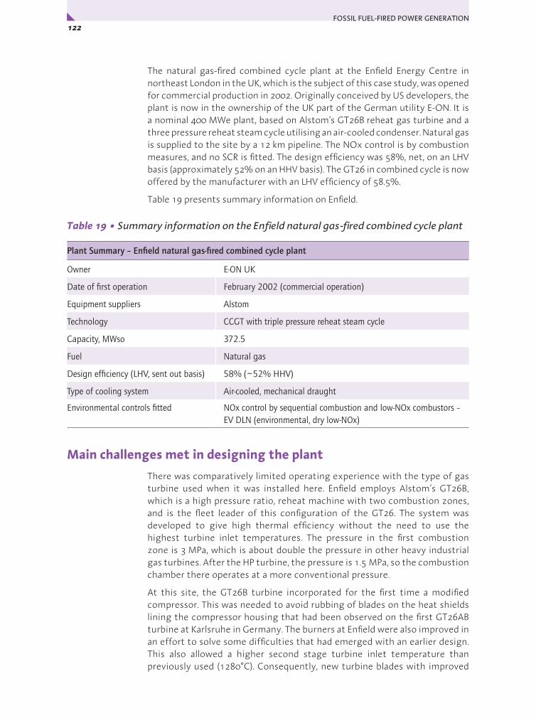
FOSSIL FUEL-FIRED POWER GENERATION 122x
The natural gas-fired combined cycle plant at the Enfield Energy Centre in northeast London in the UK, which is the subject of this case study, was opened for commercial production in 2002. Originally conceived by US developers, the plant is now in the ownership of the UK part of the German utility E-ON. It is a nominal 400 MWe plant, based on Alstom’s GT26B reheat gas turbine and a three pressure reheat steam cycle utilising an air-cooled condenser. Natural gas is supplied to the site by a 12 km pipeline. The NOx control is by combustion measures, and no SCR is fitted. The design efficiency was 58%, net, on an LHV basis (approximately 52% on an HHV basis). The GT26 in combined cycle is now offered by the manufacturer with an LHV efficiency of 58.5%.
Table 19 presents summary information on Enfield.
Table 19 • Summary information on the Enfield natural gas-fired combined cycle plant
Plant Summary – Enfield natural gas-fired combined cycle plant
Owner E-ON UK
Date of first operation February 2002 (commercial operation)
Equipment suppliers Alstom
Technology CCGT with triple pressure reheat steam cycle
Capacity, MWso 372.5
Fuel Natural gas
Design efficiency (LHV, sent out basis) 58% (~52% HHV)
Type of cooling system Air-cooled, mechanical draught
Environmental controls fitted NOx control by sequential combustion and low-NOx combustors – EV DLN (environmental, dry low-NOx)
Main challenges met in designing the plantThere was comparatively limited operating experience with the type of gas turbine used when it was installed here. Enfield employs Alstom’s GT26B, which is a high pressure ratio, reheat machine with two combustion zones, and is the fleet leader of this configuration of the GT26. The system was developed to give high thermal efficiency without the need to use the highest turbine inlet temperatures. The pressure in the first combustion zone is 3 MPa, which is about double the pressure in other heavy industrial gas turbines. After the HP turbine, the pressure is 1.5 MPa, so the combustion chamber there operates at a more conventional pressure.
At this site, the GT26B turbine incorporated for the first time a modified compressor. This was needed to avoid rubbing of blades on the heat shields lining the compressor housing that had been observed on the first GT26AB turbine at Karlsruhe in Germany. The burners at Enfield were also improved in an effort to solve some difficulties that had emerged with an earlier design. This also allowed a higher second stage turbine inlet temperature than previously used (1280°C). Consequently, new turbine blades with improved

123Chapter 3 • Case Studies – Natural Gas-Fired Plant: Europe y
air cooling and protective coatings were fitted in this turbine for the first time. The higher temperature did allow the turbine exhaust temperature to be higher (at 645°C), which was helpful for steam cycle efficiency.
The high pressure ratio gas turbine at Enfield required the natural gas fuel to be at 5 MPa. However, natural gas supplied for the site can be at widely ranging pressures (3 to 8 MPa). This necessitated including a compressor station, with 2 x 100% compressors providing gas at 5 MPa when supply pressure is low. At times when pipeline pressure is sufficiently high, a bypass system allows the gas to be used directly. Abstraction of cooling water from the adjacent River Lea was not permitted and hence steam is cooled using a 25 cell air cooled condenser.
Overall configuration
The overall configuration is shown in Figure 25. It uses an Alstom KA26-1 combined cycle system based around a GT 26B reheat gas turbine. In the gas turbine, air is compressed in an axial flow, rotating compressor then natural gas is combusted in it, raising the temperature to 1140°C. The hot product gases are expanded through a high pressure turbine, additional natural gas is added and burnt, raising the temperature again (to 1280°C), and the gases are further expanded through the remaining stages of the turbine.
LP HPIP IP
Feedwater pumps
HPIP LP
Feedwater tank
Serviceejectors
Startupejector
Boiler & steam drums
Condensate delivery pumps
CMPSRHPLP Air cooledcondenserClutch
Gen.
GT26Gas turbine
Naturalgas
Naturalgas
Combustionchambers
AirExhaust gasHPturbine
LPturbine Compressor
Feedwatervalves
Bypass lines
LP
Steam turbine
HPG
Condensate tank
Cou
rtes
y E-
ON
UK
Figure 25 • Enfield natural gas-fired combined cycle plant overall configuration

FOSSIL FUEL-FIRED POWER GENERATION 124x
The expanding gases cause the turbine to rotate, and the turbine directly drives the compressor and a generator. The hot turbine exhaust gases are used to raise superheated and reheated steam in a heat recovery steam generator (HRSG). The emerging cooled gases (at around 100°C) are then sent to the stack.
The other main component of the combined cycle system is a subcritical reheat steam turbine supplied by Alstom, which is also coupled to the generator. The steam turbine utilises steam from the HRSG at three pressure levels (10.7 MPa/566°C; 2.4 MPa/560°C; 0.4 MPa/saturated). The steam is expanded in the high pressure turbine, reheated in the HRSG, then expanded again, with additional steam from the HRSG, before being condensed and returned as water to the boiler. Output from the gas turbine is varied by adjusting the compressor’s inlet guide vanes. The steam turbine output also decreases as less heat is available for steam raising. The steam turbine cycle uses an air-cooled condenser.
Table 20 • Selected performance-related information on the Enfield combined cycle plant
Annual operating efficiency (LHV, sent out basis) 52% (for a 40% capacity factor) (~46% HHV basis)
Fuel Natural gas
Gas turbine output, MWe, at MCR 244
Steam turbine output, MWe, at MCR 134.9
Gross power output, MWe, at MCR 378.9
Net power output, MWso, at MCR 372.5
Auxiliary power consumption, MWe at MCR 6.4
Gas turbine type GT26B (reheat; 30:1 pressure ratio)
Gas turbine inlet temperature Stage 1 (HPT): 1140°C – Stage 2 (LPT): 1280°C
Steam conditions 10.72 MPa/ 566°C; 2.40 MPa/560°C; 0.412 MPa/saturated
Final feedwater temperature, °C 60
Type of cooling system Air cooling
Condenser pressure, kPa 8.5
NOx abatement systems Low-NOx burners plus sequential combustion
NOx emissions, 6% O2, dry <25 ppm at 15% O2 (equiv to <128 mg/m3 at 6% O2)
Specific capital cost, USD/kWso ~950 (1999) including IDC and owner’s costs
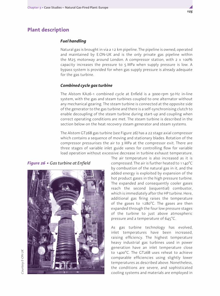
125Chapter 3 • Case Studies – Natural Gas-Fired Plant: Europe y
Plant description
Fuel handling
Natural gas is brought in via a 12 km pipeline. The pipeline is owned, operated and maintained by E.ON-UK and is the only private gas pipeline within the M25 motorway around London. A compressor station, with 2 x 100% capacity increases the pressure to 5 MPa when supply pressure is low. A bypass system is provided for when gas supply pressure is already adequate for the gas turbine.
Combined cycle gas turbine
The Alstom KA26-1 combined cycle at Enfield is a 3000 rpm 50 Hz in-line system, with the gas and steam turbines coupled to one alternator without any mechanical gearing. The steam turbine is connected at the opposite side of the generator to the gas turbine and there is a self-synchronising clutch to enable decoupling of the steam turbine during start-up and coupling when correct operating conditions are met. The steam turbine is described in the section below on the heat recovery steam generator and steam systems.
The Alstom GT26B gas turbine (see Figure 26) has a 22 stage axial compressor which contains a sequence of moving and stationary blades. Rotation of the compressor pressurises the air to 3 MPa at the compressor exit. There are three stages of variable inlet guide vanes for controlling flow for variable load operation without excessive decrease in turbine exhaust temperature.
The air temperature is also increased as it is compressed. The air is further heated to 1140°C by combustion of the natural gas in it, and the added energy is exploited by expansion of the hot product gases in the high pressure turbine. The expanded and consequently cooler gases reach the second (sequential) combustor, which is immediately after the HP turbine. Here, additional gas firing raises the temperature of the gases to 1280°C. The gases are then expanded through the four low pressure stages of the turbine to just above atmospheric pressure and a temperature of 645°C.
As gas turbine technology has evolved, inlet temperatures have been increased, raising efficiency. The highest temperature heavy industrial gas turbines used in power generation have an inlet temperature close to 1400°C. The GT26B uses reheat to achieve comparable efficiencies using slightly lower temperatures as described above. Nonetheless, the conditions are severe, and sophisticated cooling systems and materials are employed in C
ourt
esy
E-O
N U
K
Figure 26 • Gas turbine at Enfield

FOSSIL FUEL-FIRED POWER GENERATION 126x
all advanced gas turbines such as the GT26B. These include advanced alloys and thermal barrier coatings and blade cooling systems with air channels aspirating through holes in the blades. Air for the latter is supplied by the gas turbine compressor. The two combustion zones in the sequential combustion system each use annular (or ring-type) low-NOx burners.
There is no need for an airheater on gas turbine combined cycle systems, and the exhaust gases from the gas turbine are readily cooled to a sufficiently low temperature (~100°C) for high efficiency using the heat recovery steam generator only. This is possible because acid dew point corrosion is not generally an issue with the ultra-low sulphur fuels normally burned in gas turbines.
NOx control
The gas turbine uses a sequential annular combustion system (known as SEV) and low-NOx burners (known as EV combustors) to keep NOx production low. These combustors inject the natural gas through a number of nozzles arranged around the combustion zones, which surround the rotor. Emissions are <25 ppm at 15% O2, dry, which is equivalent to <128 mg/m3 at 6% O2, dry. There is no downstream NOx removal. In parts of the world where very low NOx emissions are required from combined cycle gas turbines, SCR systems are incorporated into the heat recovery steam generator.
Heat recovery steam generator and steam systems
The steam generation and utilisation cycle is included in Figure 25. The heat recovery steam generator (HRSG) has no supplementary firing and raises steam at three pressures and produces reheat steam purely from the heat in the 645°C gas turbine exhaust gases that are ducted to it. Combined cycles have heat available over a smaller range than steam only plant and the best means of utilising that heat is to evaporate the water at more than one pressure/temperature condition. The HRSG contains a series of water filled tubes in which the steam is produced and superheated and reheated. There are steam drums at all three pressures to separate the steam for further heating, and to enable the three separated water streams to be recirculated to the HRSG for further evaporation. The HRSG operates with natural circulation.
The flue gas temperature at the exit to the steam generator is 107°C. Some HRSGs have duct burners to allow supplemental firing with additional gas to provide an extra means for meeting load swings, but this system was not required at Enfield.
The three cylinder steam turbine consists of a high-pressure turbine, an intermediate pressure turbine and a low pressure turbine. Steam conditions are 10.7 MPa/566°C; 2.4 MPa/560°C; 0.4 MPa/saturated. The high pressure superheated steam from the HRSG feeds the high pressure steam turbine. Steam leaving the HP turbine is reheated in another bank of tubes in the HRSG, superheated intermediate pressure steam from the HRSG is added, then this steam expanded through the intermediate pressure steam turbine from where it flows on to the low pressure turbine. LP steam from the boiler

127Chapter 3 • Case Studies – Natural Gas-Fired Plant: Europe y
is also added. The steam leaving the LP cylinder is ducted to the air-cooled condenser, which is a forced draught air-cooled system with 25 electrically driven fans. The condenser pressure is 8.5 kPa. Ejectors are provided to maintain condenser vacuum. The water consumption of the plant is very low because of the dry cooled condenser.
Water from the deaerator is pumped using electrically driven feed pumps operating at low, intermediate and high pressure. Steam is extracted from the turbine for use in ejectors, feedwater heating and deaeration. The final feedwater temperature is 60°C.
Economics
NGCC projects are lower in investment requirements than coal-fired projects in OECD locations. In this case, the total project cost was around £220 million in 1999 (USD355 million in 1999), or around 950 USD/kWso. The turnkey power plant contract accounted for approximately 50% of this. Gas turbine combined cycle plants are also capable of short construction times because equipment is not project specific (except 50Hz / 60 Hz machines) and much of it can be delivered to site pre-assembled. Construction time here was 22 months. The plant currently operates on a flexible, two-shift basis. There are only 12 operating staff. Availability is high, at 95%. The only real disadvantage to the economics of these types of plants lies in their strong dependence on fuel costs, which form a very large proportion of the electricity production cost. This leaves them vulnerable to the greater volatility in gas prices than those of coal. However, efficiencies are gradually rising as gas turbines are developing and the technology looks set to remain one of the cornerstones of utility power production in many parts of the world with access to natural gas.
Commentary
This is a good example of a modern, high performing natural gas-fired plant, which uses combined cycle technology to achieve very high efficiency. The design efficiency is 58% net, LHV basis. The gas turbine model used here, Alstom’s GT26B reheat machine, illustrates the willingness of manufacturers to push the technology on to even higher future performance through innovation. Other developments by the turbine manufacturers include the development of advanced catalytic burners that will eventually lead to NOx emissions that are currently achievable only with the use of SCR systems in the heat recovery boiler, use of compressor intercoolers (pre-coolers for the inlet air are used in hot countries at present to increase gas turbine performance), steam cooling of blades (in H series) and further new materials for higher temperatures. Turbine blades used in high temperature gas turbine engines such as the GT26B are fabricated from high temperature nickel-based superalloys having a single crystal structure for high oxidation resistance and mechanical strength at elevated temperatures. Developments of these alloys and coatings and means of fabrication are continuing for even better strength and resistance. Further developments in film cooling can also be expected.

FOSSIL FUEL-FIRED POWER GENERATION 128x
Combined cycle gas turbine systems fired on natural gas or distillate oils are now well established in the power generation industry. Their economics may be less favorable than they were a few years ago because of high fuel costs, but their high efficiency, low capital requirements and short construction time mean that they will continue to be selected for many power projects. They are also a link to coal-fired combined cycles, notably those based on gasification. Developments in gas turbine and combined cycle technologies and manufacturing focused around natural gas flow down to commercial offerings for use on coal derived gases.
The high net efficiency of 52%, LHV basis, that has been achieved at 40% capacity factor illustrates the flexibility of these systems. Alstom say that the burner design and sequential combustion also give the engine low emissions over a wide load range.
The design ambient conditions at Enfield were fairly similar to the ISO conditions that are generally used in expressing gas turbine performance. It is worth noting that the efficiency and output of gas turbines do vary considerably with inlet air temperature and pressure, unlike for pulverised coal combustion plants, which are most susceptible to the cooling system temperature. In a northern climate, gas turbine capacity can fluctuate by as must as 20% between lowest values in summer and highest in winter.
Acknowledgements
Allan Jones, E-ON UK, for facilitating selection of EnfieldMike Garwood, E-ON UK, for arranging data collection
Background sources
Smith D, Enfield Energy Centre GT26 first to 265 MWe, Modern Power Systems (April 2000)

129Chapter 3 • Case Studies – IGCC Technology Review y
IGCC TECHNOLOGY REVIEW
Introduction
This section looks at some example coal-fuelled integrated gasification combined cycle (IGCC) plants, planned generation projects and the emergence of associated reference designs, and considers likely future developments in the technology. Currently, a small number of demonstration and ex-demonstration plants are operating at commercial scale.
While there are continuing developments, coal gasification itself is not novel. Its use in the production of hydrogen and carbon monoxide as an initial processing step is well established in the chemicals industry. The application of coal gasification to power generation is also not new at such sites. However, the commercial ordering of coal-fuelled IGCC as a complete system for power generation by utilities has yet to occur. This situation could change with the recent formation of industrial groupings that aim to offer plants with full commercial guarantees after an initial front end engineering study. Interest in IGCC is also being stimulated by interest in CO2 capture and storage, for which there may be potential advantages over other systems.
The basic principle of IGCC was described earlier and shown in Figure 3. There are many possible configurations because gasifier designs vary significantly and IGCC has a large number of process areas. Gas cleaning in IGCC is typically effected by dry removal of solids from the raw gasifier product gas followed by cold wet scrubbing. Deep cleaning is necessary to protect the integrity of the gas turbine, but it also results in emissions of particulates and SO2 being very low. Totally dry gas clean-up may eventually be applied, but is not yet reliably demonstrated.
There are three general types of gasifier: entrained bed, moving bed (also confusingly referred to as fixed bed), and fluidised bed. IGCCs have usually been based around entrained gasifiers because of their fuel flexibility, their production of high pressure steam, and the lack of tars in the product gas. Entrained gasifiers operate in slagging mode, and most are oxygen blown. In an IGCC, the oxygen production plant can take its compressed air supply from the gas turbine compressor or from separate motor driven compressors or a combination of both. The latter is favoured for future designs as it gives more rapid start-up and greater operating flexibility, while maintaining the efficiency advantage of gas turbine air extraction.
IGCC and CO2 capture and storage
IGCC can be configured to be readily adaptable for removal of carbon from the system before the fuel gas is fired. The carbon monoxide in the gasifier product gas would be converted to additional hydrogen plus CO2 using a shift reaction. The CO2 would be separated for storage, then the hydrogen would be burnt in the gas turbine with nitrogen as a diluent. CO2/hydrogen separation is normal practice in ammonia manufacturing plants using coal

FOSSIL FUEL-FIRED POWER GENERATION 130x
gasification. There is also experience in industry of industrial turbines up to E class (inlet temperatures around 1100°C) operating on process gases containing up to 95% hydrogen, and there are activities to develop high temperature hydrogen turbines under the EU ENCAP project and the US DOE Advanced Turbines Program.
Pre-combustion capture of carbon from the fuel gas would reduce efficiency, but currently it seems that this penalty could be lower than for PCC with CO2 capture by scrubbing of flue gas, as the CO2 is at higher pressure and concentration. It might be possible to improve the economics by taking off some of the hydrogen and/or syngas for chemical processing to give additional products.
EfficiencyNet efficiency for non-CO2 capture IGCC is about 40-43% on bituminous coals on an LHV basis (around 38-41%, HHV basis). Over 43% (LHV basis) is achieved in one of the European plants with an E-class gas turbine. Gas turbines that have become available more recently for use on coal-derived gases should enable this to be bettered now. Power is needed for solids handling, oxygen production and for fuel gas cleaning, so efficiency is lower than from natural gas-fired combined cycles using similar turbines. Future expected developments aim to take net efficiencies beyond 50%, LHV basis, through:
y detailed optimisation and optimal integration of the gasification and power generation blocks;
y advances in gas turbine technology (the largest contribution);
y development of hot gas cleaning processes for the gasifier product gas;
y advanced air separation technologies (see below).
Note that PCC development programmes are targeting similar efficiency levels (over 50%) within the next ten years (see chapter 4).
Both the power consumption and cost of conventional cryogenic oxygen plants currently penalise IGCC economics. Alternative technologies, currently at the pilot scale, that avoid cryogenics are ceramic ion transport membranes (ITM) being developed by Air Products with US DOE funding, and the ceramic autothermal recovery (CAR) system being developed by BOC, now part of Linde. These are expected to be commercially available within 5-10 years and should give savings in capital cost and energy demand for the oxygen plant compared with cryogenic plants.
The efficiency values above are for ‘conventional’ IGCC, that is, without CO2 capture and storage. Inclusion of the latter will reduce efficiency by 6-8 percentage points, but possibly less by using advanced separation technologies that could become available in the longer term. An example is shift reaction/hydrogen membrane reactor systems. Depending on the type of gasifier used, additional water may be required to drive the shift reaction under CO2 capture operation.
131Chapter 3 • Case Studies – IGCC Technology Review y
Emissions
Emissions of SO2 from IGCC are low. For example, the Puertollano IGCC in Spain achieves an average 20.8 mg/m3 at 6% O2, dry.
NOx emissions are low because of control of flame temperature by mixing the fuel gas with nitrogen, water or steam. The NUON Power IGCC at Buggenum in Holland achieves <10 ppm, equivalent to 50 mg/m3 at 6% O2 without the need for a selective catalytic reduction system.
Dust emissions from IGCC are extremely low. At Puertollano, the IGCC achieves an average 0.05 mg/m3 at 6% O2, dry.
Without special measures, the emission of mercury from IGCC plants depends on the particular installation. However, the concentrated, pressurised stream of fuel gas is expected to give up to a ten-fold saving in the cost of removal in cold gas clean-up systems compared with PCC. Tests at the Polk County IGCC showed that sorbent beds based on activated carbon impregnated with sulphur were highly effective, as has 15 years of (non-IGCC) operation using carbon beds on gasifier product gas at the Eastman Chemical Company’s plant at Kingsport, USA.
The application of CO2 capture will make achieving low NOx emissions more difficult to achieve as a hydrogen burning turbine will be used. There are programmes aimed at developing advanced combustors to address this challenge, but Siemens have already reported 15 ppm NOx levels (equivalent to 50 mg/m3 at 6% O2) using steam and nitrogen dilution.
Economics
There is more uncertainty in coal-fuelled IGCC costs compared with PCC because there are no recently built IGCC plants and the existing ones were constructed as demonstrations. Availabilities of IGCC have also not yet reached the demonstrated level of operating PCC units. The specific investment cost of IGCC is estimated as being about 20% higher than that of PCC, although the cost would vary with type of coal. IGCC cost also varies with the technology and configuration adopted, for example whether or not a spare gasifier train is required to increase availability for certain types of gasifier.
Suppliers have targets to bring the specific capital cost for reference designs to within 10% of that of PCC and R&D is aimed at further cost reductions. This has to be seen within the context that PCC suppliers are naturally also engaged on efforts to drive down the cost of their own systems, so it is not clear at this stage where cost relativities will ultimately lie. Also, the capital cost of all power projects have risen considerably over the last few years because of the impact of higher energy prices on steel and concrete prices. Estimates of generating costs are made in Chapter 4.
FOSSIL FUEL-FIRED POWER GENERATION 132x
EU plants
The two principal commercial scale IGCC plants in Europe are in Holland and Spain. The former uses international coals, the latter uses a blend of high ash coal and high sulphur petcoke. The Shell gasifier-based IGCC at Buggenum (250 MWe) in the Netherlands, owned by NUON Power, has been operating commercially with increasingly good availability since 1998, following a demonstration phase. This plant was conceived at the end of the 1980s and uses a Siemens V94.2 gas turbine of 1120°C inlet temperature and the net efficiency is over 43% (LHV basis). A single stage up-flow Shell entrained flow, oxygen blown, dry feed gasifier is used. This is of the membrane wall type and operates at a temperature of 1500°C and a pressure of 2.8 MPa. The membrane wall of the gasifier has not needed repair or replacement since plant start-up in 1993/4 and it is anticipated that it will have a lifetime in excess of 25 years. The raw gas produced is quenched to 900°C at the gasifier exit by the addition of a recycle stream of cooled, dedusted gas, before being sent to a down-flow water tube convective syngas cooler.
In the first stage of gas clean-up, flyash and small particulates are removed by Schumacher ceramic candles in a filter unit operating at 250-285°C. In 1997, the filter elements were changed from DIA-SCHUMALITH F-40s to more advanced 10-20 variants for improved filtration efficiency, improved element cleaning and reduced pressure drop. Annual filter overhauls were thereby eliminated and availability of the filter system significantly increased. Dry gas cleaning is followed by wet scrubbing to remove water soluble contaminants, and sulphur-containing compounds are subsequently removed using the Sulfinol gas scrubbing process.
A Siemens V94.2 gas turbine with twin silo combustors is used to fire the syngas. The subcritical steam turbine is a Siemens KN model. In order to maximise thermal efficiency, the cycle uses full integration with extraction of air from the gas turbine compressor for the air separation unit. Full integration has resulted in a lengthy start-up time and limited load ramp rate. Availability was also initially adversely affected by the high probability of overall trip when one island failed.
Problems with turbine humming arose on firing the syngas and these were solved by modifications to the burners and control systems. Other improvements made at the plant to improve performance and profitability have included updating the gasifier ceramic heat skirt with a water cooled equivalent (current Shell design), the use of oxygen and nitrogen buffer capacity to maintain gasifier operation in the event of a gas turbine or ASU trip, and adding the facility for injection of natural gas to increase load ramping and improve operational flexibility. Measures to enable the gas turbine to be reliably started using syngas are currently being introduced.
In 2004, total operating time was around 8000 h on natural gas plus syngas, and the plant has achieved 80% availability on syngas.
Tests have been carried out on the co-gasification of biomass fuels to meet Government subsidy requirements. A maximum of 30 wt % co-gasification of

133Chapter 3 • Case Studies – IGCC Technology Review y
bio-fuels was used and the plant demonstrated good fuel flexibility although some operational problems were encountered, including some syngas cooler fouling from the addition of 4-5% sewage sludge. Consideration is being given to finding a means of increasing plant output to its coal-fired rating of 250 MWe when co-gasifying.
Feasibility studies are being carried out on the possibility of reducing the degree of plant integration, although this may impact on plant heat rate. Consideration is also being given to possible routes forward for CO2 capture and storage and the production of hydrogen at the plant.
The Krupp-Uhde PRENFLO gasifier based EU-funded IGCC at Puertollano, owned by ELCOGAS, in Spain (300 MWe), has been operated since 1996. The gasification system is similar to the Shell process for coal gasification. Uhde, the PRENFLO developers, are now associating with Shell and supply Shell gasifiers. The reaction chamber has an integral, rather than a separate cooling system that produces steam. Gasification takes place at a pressure of 25 bar and temperature of 1200-1600°C. The raw gas is cooled from 1550°C to 800°C by mixing with quench gas before reaching the first of the two steam generators that produce high and medium pressure steam for the combined cycle. The plant has a Siemens V94.3 gas turbine and the net efficiency is over 42% (LHV basis) on the mixed fuel. Ceramic filters operating at about 240°C remove particulates before the gas scrubber. Full integration of the oxygen plant with air supply from the gas turbine compressor is employed.
Many of the causes of unavailability have not concerned the gasification process itself. Among the technical issues, subsequently addressed, that have affected plant performance at different times are fuel supply system problems, leakage of gasifier membrane tubes due to blockages and erosion, and gas piping corrosion. The two filter vessels initially contained DIA-SCHUMACHER F40 elements. However, early operations resulted in a high rate of breakage, so, in 2000, the elements were changed to 10-20 variants as at Buggenum. In addition, fouling of waste heat boiler surfaces was addressed by decreasing the gas inlet temperature to the cooling surfaces, increasing quench flow and increasing gas velocity. Blockages in the slag removal system were solved by improving the combustion control equipment. Gas turbine problems included vibration and humming and misalignment of the combustion chamber tiles. Experience from Buggenum was valuable in solving some of these: new burners and controls have greatly improved operation.
Since 2000, improved syngas availability has also been achieved by adjusting the proportion by mass of coal fed and by use of better off-line cleaning cycles for the candle filters. Currently a 50/50 mixture is being used. Plant start-up is comparatively slow because of the highly integrated nature of the plant and ELCOGAS would use partial integration in any future installation.
Techno-economic feasibility studies on co-gasification have been carried out for a number of possible feedstocks and several short duration full scale IGCC tests have been carried out using cattle residues (Meat and Bone Meal - MBM). In all, a total of 93.3 t of MBM was successfully gasified with the plant’s coal/petcoke feed. There was no adverse impact on syngas quality, gasifier
FOSSIL FUEL-FIRED POWER GENERATION 134x
control, slag discharge, gasifier waste heat boiler operation, wet gas cleaning or hot gas filter operation. The introduction of MBM into the feed increased levels of Na and P compounds in the fly ash and increased levels of Na in the slag.
ELCOGAS is involved in a CARNOT project examining the optimal design for new IGCC units that will include CO2 capture and hydrogen production.
USA plantsIGCC plants currently operating in the USA are the Tampa Electric Polk project and the Wabash River coal gasification project. The Tampa Electric Polk project uses an oxygen-blown GE (at one time, Texaco) down-flow slurry-feed gasifier with radiant cooler and a GE 7FA gas turbine. The 250 MWe plant commenced operation in September 1996 in a commercial demonstration under the US DOE CCT Program. Unlike at the European plants, the air for oxygen production is supplied from a separate compressor dedicated to the air separation unit, not from the gas turbine (recently, some air extraction from the gas turbine has been incorporated).
The gas emerging from the radiant cooler section of the gasifier is cooled in two parallel fire tube boilers. After leaving the convective steam generators, the gas trains are cleaned of particulates in water scrubbers then sulphur compounds are removed from the combined gas stream in a methyl diethanolamine (MDEA) acid gas removal system (a chemical scrubbing system). The clean gas is reheated before combustion in the gas turbine. Diluent nitrogen is also fed to the gas turbine combustor to control flame temperature to reduce the production of NOx. There were the usual initial bedding-in problems, but the unit now operates with good availability.
Difficulties experienced included deposition/corrosion in some raw/clean gas heat exchanger tubes (solved by removal of the exchangers involved), plugging of convective syngas coolers (modifications have controlled this) and a lower carbon conversion than anticipated.
The gas turbine performed well on the gasifier product gas and the plant net efficiency was 35.4% on an HHV basis (36.7% LHV basis), as determined during the CCT phase on a 100% coal feed (Peabody Camp Kentucky No 9). This was penalised by the carbon conversion being lower than the anticipated 97.5-98%. The plant has processed a number of coals as well as a blend of high sulphur petroleum coke with coal. The unit operates with 78% availability on syngas. Back-up fuel increases this to 96%. The four and a half year demonstration ended in October 2001 and the plant now operates commercially. Distillate fuel systems enable the General Electric STAG 107FA gas turbine combined cycle system to generate during gasifier non-availability.
The 260 MWe Wabash River coal gasification project, Terre Haute, Indiana, owned by SG Solutions (gasifier facilities) and PSI Energy, is based around the two-stage, slurry feed, up-flow gasifier, developed originally by Dow Chemical Company. It is a re-powering project established under the US DOE CCT Program and uses a General Electric Frame 7FA gas turbine and an existing steam turbine. There are two 100% capacity gasification trains.
135Chapter 3 • Case Studies – IGCC Technology Review y
Both high sulphur Illinois #6 bituminous coal and petroleum coke have been gasified. Since 2000, the gasifier has been operated on 100% petroleum coke. Air for the oxygen separation plant is supplied by a dedicated compressor and not from the gas turbine compressor.
Raw gas from the top of the gasifier is cooled to 370°C in a vertical firetube syngas cooler, and a subsequent candle filter unit removes fly ash and char for recycle to the first stage of the gasifier. The filtered gas is cooled then cleaned of sulphur compounds in an MDEA scrubber. The clean gas is reheated and moisturised to control NOx emissions before combustion in the gas turbine. The HRSG provides superheated steam for the retained 1950s vintage 104 MWe reheat steam turbine. Net efficiency is over 38% on an HHV basis, equivalent to around 40%, net, LHV basis.
Ash deposits on the walls of the second stage of the gasifier and downstream piping were cured by modifications to refractories and installing a screen at the syngas cooler inlet. Routine removal of deposits from the syngas cooler tubes is required at scheduled outages.
The particulate removal system accounted for nearly 40% of downtime in the first year of operation. Here, a change from ceramic candle filter elements to metallic candle elements was used to improve reliability. Corrosion of metallic filters and filter blinding were also been addressed with better materials and by modifying the gas distribution in the filter vessel and improving pulse cleaning. The gas turbine and related components operated largely as expected over the course of the project, with few syngas-related failures. The plant is continuing to operate commercially. ConocoPhillips now owns the gasification technology and is marketing it under the name E-Gas.
Japan plantIn Japan, the Clean Coal Power R&D Co., Ltd. (CCP) is constructing a 250 MWe IGCC demonstration project at Nakoso power station, Iwaki City, based on the MHI air-blown, two-stage, dry-feed entrained flow gasifier and an MHI 701DA gas turbine. Japan’s Ministry of Economy, Trade and Industry (METI) is funding 30% of the project costs. CCP was established by a consortium including nine leading Japanese utilities.
The gasifier has water cooled membrane walls, instead of thick refractories, to reduce maintenance requirements. A similar system is used in Shell and Future Energy coal gasifiers. Part of the air for gasification will be extracted from the gas turbine compressor, and the air will also be oxygen enriched. No quench gas will be used. The system will use a low grade coal. Char will be separated from the gases leaving the gasifier using cyclones and high temperature filters and the char will be recycled to the gasifier. Chemical scrubbing (using MDEA) will clean the de-dusted gas of sulphur compounds. The gas turbine has an inlet temperature of 1200°C. Target net efficiency is 42% (LHV basis). An SCR system is included to meet NOx limits of 5 ppm at 16% O2, equivalent to 30 mg/m3 at 6% O2. The demonstration plant, due to start operation in 2007, is located 100 miles north of Tokyo. The system will effectively provide reference plant designs based on M501F and, eventually, M501G gas turbines, with net efficiencies of 45% and 48% (LHV basis), respectively.

FOSSIL FUEL-FIRED POWER GENERATION 136x
Planned IGCC projects and reference designs
There are coal IGCC projects in prospect in a number of other locations including the USA, Australia, Holland, United Kingdom, Germany, China and India. Many of these are being planned to include the facility for CO2 capture and storage. Some believed to be closest to realisation are briefly discussed below.
In the USA there are new IGCC plants being progressed basically as commercial projects, but incentives such as investment tax credits and permitted higher power sales prices will cover some of the additional cost of selecting IGCC technology. There are planned projects at the following locations (all oxygen-blown entrained gasifiers, apart from the transport reactor demonstration, which will be air-blown):
y Duke Energy, Edwardsport, Indiana – GE-Bechtel
y AEP, Meigs County, Ohio and Mason County, W. Virginia – GE-Bechtel
y Mesaba Energy Project, Minnesota – ConocoPhillips E-Gas (CCPI Demo)
y Southern Company Services, Orlando, FL – Transport Gasifier (CCPI Demo).
GE Energy and Bechtel Power in August 2006 signed an agreement with American Electric Power (AEP) to proceed with the front end and engineering design (FEED) phase for a, 630 MWe IGCC plant in Mason County, West Virginia. The organisations had already signed a FEED agreement for a similar project in Meigs County, Ohio. Duke Energy, Indiana, is also expected to order a similar system from GE-Bechtel for its Edwardsport plant site for operation in 2011. These designs are the result of the development plan by GE-Bechtel for a standardised reference plant capable largely of being replicated for other locations and so contribute to bringing the capital cost down to no more than 10% above that of supercritical PCC, in order to give a similar generating cost to PCC.
The reference plant consists of two trains of 300 MWe, with two gas turbines, two gasification and gas cleaning systems, two HRSGs and a single reheat steam turbine. Design availability will be 85% on syngas (currently operating PCC plants achieve availabilities in excess of 90%). Turndown to 50% will use both gasifiers. Turndown to 30% will use one gasifier. The system will be designed to remove more than 90% of the mercury and it will be possible for addition of selective catalytic reduction for increased NOx removal. CO2 capture is also possible but CO2 capture is not currently planned for initial plant operation. The FEED activities will produce a firm price, with guaranteed schedule, output, heat rate and emissions, as well as an EPC contract. This should facilitate obtaining financing for plants.
The Mesaba project being developed by Excelsior Energy is a USDOE CCPI demonstration. The US DOE will have a small share of the cost as part of its plans to encourage IGCC developments to process indigenous coals. Siemens Power Generation has developed a 630 MW IGCC reference plant power block to match the ConocoPhillips E-Gas gasification system based on two SGT6-5000F gas turbines, two reheat HRSGs, and a single steam turbine. SCR can
137Chapter 3 • Case Studies – IGCC Technology Review y
also be included in the HRSG system and CO2 capture would be supported if required. The Mesaba project will capture most of the potential mercury emissions from the coal and will be CO2 capture ready. FEED activities by Fluor and Siemens are complete and the projected year for commercial operation is 2010. ConocoPhillips project 81% availability for a reference plant. Additional of a spare 50% gasifier would increase this by 10% at an additional cost of approximately 8% for the plant. It is planned to use two full trains plus a spare, to achieve 90% availability.
Siemens Power Generation has also acquired the Gaskombinat Schwarze Pumpe (GSP) (Future Energy) gasification process and is designing a reference plant to match it, to process various fuels, including lignite, anthracite and refinery residues. This is an entrained-flow system, in which the fuel can be fed either pneumatically or as slurry.
As with the GE-Bechtel reference plant, Siemens’s aim has been to achieve packages that can be replicated readily to encourage uptake of the technology.
Another USDOE-supported CCPI project will be in Florida. This is the Southern Company Services, Orlando, 284 MWe Transport Gasifier demonstration. The transport gasifier (which uses a rapidly circulating fluidised bed) is better suited to low-rank coals because of its lower operating temperature. This is an air blown demonstration, although the gasifier has been operated at pilot scale on oxygen. Commercial operation is anticipated for 2010.
NUON Power plan to build a 1200 MWe IGCC (the Magnum project) at Eemshaven with commissioning in 2010. Shell gasifiers will be used, and an option for later incorporation of 40% CO2 capture is being considered.
In India, BHEL is developing an air blown pressurised fluidised bed gasification based IGCC system. There are plans for scaling up the process to 100-125 MWe, with the construction of a demonstration plant at Aurya in Uttar Pradesh. There are further plans to follow the demonstration with the construction of a 400 MWe plant in 2012.
IGCC projects incorporating CO2 capture and storage
In Canada, EPCOR plans to host the CCPC’s commercial scale demonstration of a gasification combined cycle with CO2 capture and storage at their Genesee power generation site. The plant will be fuelled on sub-bituminous Albertan coal. Two thirds of the funding is in place for the FEED activities. EPCOR have had discussions with all the main IGCC technology providers and will select the preferred technology before the end of 2007. CO2 will be used for enhanced oil recovery about 100 km away.
The Monash Energy Project in Australia is a Victorian lignite IGCC plus synfuels demonstration project to incorporate drying of this high moisture content fuel before gasification. Anglo Coal’s collaborators in the demonstration plant programme include Shell, RWE and Future Energy. A 1500 t consignment of lignite has been tested for drying by RWE and for subsequent entrained gasification in the Future Energy pilot plant in Germany.

FOSSIL FUEL-FIRED POWER GENERATION 138x
The 160 MWe demonstration plant will be CO2-capture ready and detailed studies of CO2 storage in the off-shore Gippsland Basin have been carried out. Also in Australia, Stanwell Corporation Ltd. plans to demonstrate a 60-80 MWe oxygen-blown bituminous coal IGCC with CO2 capture and storage. CO2 would be sent via a 250 km pipeline for injection into sandstone reservoirs. Shell gasification technology has been selected. Work on plant front-end design is anticipated for completion by December 2007.
RWE Power intends to construct an IGCC plant with CO2 capture and storage in Germany. Commissioning is scheduled for 2014. E-ON have plans for a plant in the UK at Killingholme, fuelled on coal and possibly coal/petcoke, that could be operational by 2011-12. CO2 would be captured for storage in formations beneath the North Sea. There are also other IGCC with CO2 capture and storage prospects in the UK (an 800 MWe IGCC with planning permission at Hatfield and two projects announced by Progressive Energy at Teesside and Drym, South Wales).
In the USA, Xcel Energy has begun preliminary design for a coal-fired IGCC in Colorado with plans for CO2 capture with storage, for construction beginning 2009, while NRG Energy, Inc. plans a 680 MWe IGCC plant with capture up to 65 percent of the CO2 at its Huntley site in western New York. BP and Edison Mission Group (EMG) are planning a USD 1 billion 500 MWe petroleum coke-fuelled IGCC adjacent to BP’s Carson refinery with CO2 capture for enhanced oil recovery. Operation is currently scheduled for 2011.
FutureGen
The US DOE’s 1 USD billion flagship FutureGen initiative is aimed at a 275 MWe IGCC plant, capturing at least 90% of the potential CO2 emissions and co-producing electricity and hydrogen with near-zero emissions. The plant is scheduled to be ready for operation in 2012. The USDOE is providing up to 75% of the funding for this project, which is being realised by the FutureGen Industrial Alliance. Among the companies in the Alliance are BHP Billiton, and Rio Tinto through its American subsidiary Energy America. Others are AEP, CONSOL, E.ON US, PPL Corporation, Xstrata Coal, Foundation Coal, Peabody Energy, Anglo American, Southern Company and China Huaneng Group (the China Huaneng Group are also implementing China’s own GreenGen Program for an IGCC demonstration). The South Korean and Indian governments are also participating through a stakeholders group operated by the US DOE. The vision is to achieve commercial plant designs no more than 10% greater in cost than conventional plants.
Site selection is in progress. Four sites in Texas and Illinois for final evaluation were announced on 25 July 2006 and the final decision will be announced summer 2007. Reviews with the major technology suppliers are ongoing and conceptual plant design and cost estimates are underway. Parallel train systems upstream of the power generation block are being considered together with a slip stream for the testing of advanced technology components. Conceptual configurations include slurry feed water quench and dry feed water quench gasification. Quench systems both cool and add

139Chapter 3 • Case Studies – IGCC Technology Review y
steam to the fuel gas, which should reduce the cost of CO2 separation as steam would otherwise need to be added separately. Transport gasifier technology will also be considered in conjunction with advanced air separation. Three coal types (Northern Appalachian, Illinois Basin and Powder River Basin) have been specified for the design and cost estimates.
Hypogen
In the EU, the European Commission’s Framework 7 Programme is likely to support the Hypogen project, which, like FutureGen, is a vision for an IGCC demonstration plant with CO2 capture and storage and hydrogen production for chemical feedstocks and possibly for use in transport. The electricity and hydrogen outputs are expected to be around 400 MW and 50 MW, respectively, and start up is scheduled for 2012. A 3-year pre-project called DYNAMIS started in March 2006 to prepare the ground for the HYPOGEN project. DYNAMIS involves 31 partners from 12 countries.
Commentary
Like PCC, IGCC holds out the prospect of clean plants for coal-fired power generation at increasing efficiencies. Neither coal gasification nor power generation from syngas is new. IGCC based on entrained gasification first featured in the Cool Water plant in the USA in the 1980s. However, the commercial ordering by utilities of coal-fuelled IGCC as a complete package purely for power generation has not materialised in the absence of a single point main contractor able to take responsibility for guarantees on installation cost, availability and efficiency. With the formation of alliances between supplier organisations, that situation could change if power generation utilities become comfortable with reference designs and cost and availability improve. To assist market entry, it would still be necessary at first for subsidies or incentives for IGCC without CO2 capture to cover the higher capital cost compared with PCC. Exceptions are where wastes and residues can be used or some of the syngas can be used, for example to produce hydrogen for refineries.
Recently established, but already with a considerable reference list of operating plants, are gasification combined cycle systems using petroleum-derived fuels such as petcoke and vis-breaker oils and similar. The latter have been constructed at oil refinery sites, where the ability to utilise such lower-value materials with their low hydrogen and high sulphur contents plus, in some locations, the availability of financial incentives have been important drivers for the refinery owners. Refinery operators are also more familiar than conventional power generation utilities with the component technologies in IGCC. The experience from these plants is providing part of the reference information for the new coal-fired IGCC designs.
IGCC in its conventional form or for CO2 capture plants does have a clear development route to higher efficiencies, through a variety of means, including non-cryogenic oxygen production, gasifier and gas clean-up

FOSSIL FUEL-FIRED POWER GENERATION 140x
advances and advances in gas turbines. With the interest in CO2 capture and storage everywhere, some of these will be carbon capture and storage plants, including utility-led as well as government-led projects.
Acknowledgements
Additional information was provided on FutureGen by Kelly Thambimuthu, Director, Centre for Low Emissions Technology, Australia, on Hypogen by John Davison, IEA Greenhouse Gas R&D Programme and on other US IGCC projects by the US Department of Energy.
Other sources
Armistead T F, Design of reference plant using IGCC technology moves forward Engineering News Record. Available from: http://enr.construction.com/news/powerIndus/archives/051014.asp (October 2005) (accessed October 2006).
Blankinship S, Coal Gasification: Players, Projects, Prospects. Power Engineering (July 2006).
ELCOGAS, ELCOGAS IGCC plant: Clean coal technology. Experience and Future. Presentation by ELCOGAS to IEA Clean Coal Representatives in Puertollano, Spain (April 2006).
Feller G J, Gadde S Introducing the SGCC6-5000F 2x1 reference power block for IGCC applications Siemens Power Generation, Inc (2006).
Gas Turbine World (July-August 2006).
GE Energy, GE Energy, Bechtel sign front end engineering design agreement for AEP’s second ‘Cleaner Coal’ project. Available from: https://www.webwire.com/ViewPressRel.asp?aId=18738 GE Energy (August 2006) (accessed October 2006).
Kalvanaraman K, IGCC: the race is on. Turbomachinery International, Available from: http://www.turbomachinerymag.com/articles/2006/0706p06.pdf (accessed December 2006) (July-August 2006).
Mills S J, Coal gasification and IGCC in Europe. CCC/113, London IEA Clean Coal Centre, 37 pp (June 2006).
Morehead H, Siemens global gasification and integrated gasification combined cycle update Gasification Technologies Council Conference (October 2006).
US DOE, Tampa Electric Polk Power Station Integrated Combined Cycle Gasification Project. Final Technical Report to US Department of Energy Office of Fossil Energy, National Energy Technology Laboratory, Morgantown, WV, USA (2002).
USDOE Wabash River coal gasification repowering project. Final Technical Report. Work performed under cooperative agreement DE-FC21-92MC29310, Clean Coal Technology Demonstration Program, US Department of Energy. Office of Fossil Energy, National Energy Technology Laboratory, Morgantown, WV, USA (2000).

141Chapter 4 • Review of Case Studies and General Conclusions y
Chapter 4 • REVIEW OF CASE STUDIES AND GENERAL CONCLUSIONS
Introduction
Coal is the single largest primary energy input to electricity generation: almost 40% of electricity is produced from coal worldwide (IEA World Energy Outlook 2006). The proportion of power generated from coal is also currently increasing. Under the IEA’s reference scenario, annual electrical generation from coal could more than double between 2004 and 2030. Even the alternative scenario of lower growth shows almost a 58% increase in annual coal generated electrical units over the same period. Table 21 shows data from the reference scenario.
Table 21 • World electricity generation from major fuels: IEA reference scenario (WEO, 2006)
Year 2004 2015 2030
Total generationTWh % share TWh % share TWh % share
17 408 100 24 816 100 33 750 100
Coal 6 917 39.7 10 609 42.8 14 703 43.6
Oil 1 161 6.7 1 195 4.8 940 2.8
Gas 3 412 19.6 5 236 21.1 7 790 23.1
Nuclear 2 740 15.7 3 108 12.5 3 304 9.8
Hydro 2 809 16.1 3 682 14.8 4 749 14.1
Renewables (excluding hydro) 369 2.1 986 4.0 2 264 6.7
There are many environmental issues arising from the use of coal in power production, and of particular concern is the emission of the greenhouse gas CO2. Because of the range of anthropogenic sources of CO2, a whole raft of measures worldwide will be needed to stabilise its concentration in the atmosphere to minimise climate change. Coal must play a major part, but the situation summarised in the paragraph above shows that policies to limit global CO2 emissions will have to accommodate the retention of coal as the principal generation fuel. If this is not done, there is a likelihood that extending electricity supply to all will be jeopardised. Reliable electricity supply is one of the basic foundations of increases in standard of living, and the developing economies have a particularly strong dependency on coal for power production, and rate of growth in coal’s contribution to electricity supply there will be greatest, as Table 22 shows.

FOSSIL FUEL-FIRED POWER GENERATION 142x
Table 22 • Developing countries’ electricity generation from major fuels: IEA reference scenario (WEO, 2006)
Year 2004 2015 2030
Total generationTWh % share TWh % share TWh % share
5 754 100 10 749 100 17 001 100
Coal 2 753 47.8 5 659 52.6 8 979 52.8
Oil 580 10.1 670 6.2 616 3.6
Gas 983 17.1 1 955 18.2 3 389 19.9
Nuclear 142 2.5 322 3.0 523 3.1
Hydro 1 239 21.5 1 928 17.9 2 827 16.6
Renewables (excluding hydro) 56 1.0 215 2.0 668 3.9
A two-pronged strategy is often proposed to limit CO2 emissions. Firstly, improving generating efficiency, to reduce the quantity of coal burned for producing each unit of power, and, secondly, introducing widespread CO2 capture and permanent storage. This series of studies relates to the first part of that strategy. General conclusions are listed later, but basically the studies have shown that the technology needed for efficient new coal-fired plants is routinely available now through designs that are not high risk or high cost, the proof being that all the pulverised coal combustion (PCC) units examined were constructed under commercial conditions. Use of high steam conditions in PCC plants is now routine, costs are not prohibitive, and reliability is good, while advantage is being taken of advances in materials and innovative designs.
These case studies are a selection from a growing number of high-performing plants: there are other examples of highly efficient units and it is no longer rare to have percentage net efficiencies around the mid-40s on a fuel lower heating value basis (low-40s on a higher heating value basis) using bituminous coals and fitted with full environmental controls. High efficiency design is very relevant to CO2 capture and storage, because there will be a major efficiency penalty from introducing it, so that such systems will need to incorporate best practice to be competitive and fuel-efficient.
IGCC could also be used for coal-fired power projects in future years once its higher cost and lower availability have been shown to be addressed. IGCC has less prominence than PCC in this report because there are no recently-built plants operating with the latest gas turbine models now proposed for use on coal-derived gas. IGCC offers generation efficiency comparable with PCC and, although it will cost more, could be valuable in accelerating deployment of CO2 capture and storage from coal-based plants.

143Chapter 4 • Review of Case Studies and General Conclusions y
Comparison of performance and costs
Table 23 summarises the specific capital costs, emissions performance and efficiencies of the plants studied. There is also a brief description of the main factors contributing to the efficiency and emissions performance. The costs obtained were in different currencies, for different base years and the basis of a few could not be established precisely, although inferences were reasonably made in those cases. Plant size also varied considerably. These costs are adjusted in an attempt to bring them closer to comparability in the discussion in the subsequent section.
Efficiency
The higher heating value based efficiency values in Table 23 for the coal-fired PCC plants have been converted to estimated equivalent “normalised” values in an effort to take account of the effects on efficiency of location and coal moisture and ash contents, as well as environmental controls, in order to assist analysis. Differences in HHV efficiency that remain should theoretically correspond more closely than the raw values to intrinsic differences arising from plant design. Detailed performance simulations for each plant would be needed to take into account all influences but would still have limitations in respect of comparisons between plants. One possible source of some of the differences in efficiencies, for example, might lie in the treatment of margins and losses. Here, indicative calculations were possible from the data obtained.
The effect of migrating to a 20°C cooling water inlet temperature design was estimated on the basis that a 10°C rise in design cooling water temperature inlet will give rise to a drop in net efficiency of approximately one percentage point. This response to change is based on Niederaussem data and the RWE booklet and an IEA CCC report referenced at the end of this chapter. Both referred to LHV-based efficiencies but the effect on HHV-based efficiencies would be similar. The effect of a coal moisture change to a reference 10% content, as received, was estimated approximately from the heat of vaporisation of water content above (or below) 10%.
The effect of moving to coals of below 30% ash content, as received, was assumed to give an HHV efficiency gain of one percentage point through reduced grinding and fuel and solids handling energy needs. The normalised plant would be expected to incorporate FGD and SCR, and these were assumed to result in efficiency reductions of 0.6 and 0.4 percentage points, respectively (the values used to modify higher heating value efficiencies in the database upgrade work by the IEA Clean Coal Centre performed in parallel with these studies). The normalised values, on the basis of design efficiencies, are shown in Table 24. It is stressed that this attempt to bring data from many places to a more common basis can give approximate estimates only because they involve simplifications and there will also be other influences operating.

FOSSIL FUEL-FIRED POWER GENERATION 144x
Tabl
e 23
• C
osts
, em
issi
ons
and
effic
ienc
ies
of th
e ca
se s
tudy
pla
nts
Plan
tSp
ecifi
c ca
pita
l cos
t, U
SD/
kWso
Emis
sion
sat
6%
O2,
dry
MW
e ne
tSt
eam
con
diti
ons
MPa
/°C
/°C
(/°C
)D
esig
n ef
ficie
ncy,
ne
t%
, LHV
and
HHV
bas
es
Ann
ual o
pera
ting
ef
ficie
ncy,
net
%, L
HV
and
HH
V ba
ses
Fact
ors
affe
ctin
g ef
ficie
ncy
and
othe
r com
men
ts
Euro
pe –
D
enm
ark:
Nor
djyl
land
- sv
ærk
et 3
1500
(200
6) fo
r ne
w 8
00 M
We
excl
udin
g ow
ners
co
sts
and
IDC
NO
x 14
6 m
g/m
3
SO2 1
3 m
g/m
3
Dus
t 18
mg/
m3
384
29/
582/
58
0/58
047
* LH
V (n
o he
at lo
ad)
44.9
HH
V (n
o he
at lo
ad)
47 L
HV
(not
ann
ual)
44.9
HH
V (n
ot a
nnua
l)H
igh
stea
m p
aram
eter
sCo
ld s
ea w
ater
coo
ling
– D
oubl
e re
heat
Low
aux
iliar
y po
wer
– E
xtre
mel
y lo
w e
mis
sion
sN
o so
lid w
aste
for d
ispo
sal
Euro
pe –
G
erm
any:
Nie
dera
usse
m K
1175
(200
2)
Tota
l pro
ject
cos
tN
Ox
<130
mg/
m3
SO2 <
200
mg/
m3
Dus
t <50
mg/
m3
965
27/
580/
600
43.2
LH
V*
37 H
HV
43.2
LH
V (b
ase
load
)37
HH
V (b
ase
load
)Li
gnite
fuel
, 50-
60%
moi
stur
e co
nten
tH
igh
stea
m p
aram
eter
sLa
rge
cool
ing
tow
er fo
r low
con
dens
er p
ress
ure
Inno
vativ
e he
at re
cove
ry s
yste
ms
Low
aux
iliar
y po
wer
Nor
th A
mer
ica
– Ca
nada
:G
enes
ee 3
1100
(200
5)O
vern
ight
cos
tN
Ox
170
mg/
m3
SO2 2
95 m
g/m
3
Dus
t 19
mg/
m3
450
25/
570/
570
41.4
LH
V40
HH
V41
LH
V (b
ase
load
)39
.6 H
HV
(bas
e lo
ad)
Mod
erat
ely
high
ste
am p
aram
eter
sLo
w a
uxili
ary
pow
erFi
rst N
Am
eric
an s
lidin
g pr
essu
re s
uper
crit.
Sub-
bitu
min
ous
coal
Asi
a –
Japa
n:Is
ogo
New
Uni
t 1
1800
(200
6)To
tal p
roje
ct c
ost
incl
New
Uni
t 2
unde
r con
stru
ctio
n
NO
x 20
mg/
m3
SO2 6
mg/
m3
Dus
t 1 m
g/m
3
568
25/
600/
610
42 L
HV
40.6
HH
V42
LH
V (b
ase
load
)40
.6 H
HV
(bas
e lo
ad)
Hig
h st
eam
par
amet
ers
Mod
erat
ely
war
m s
ea w
ater
coo
ling
Low
aux
iliar
y po
wer
– L
ow p
ower
dem
and
FGD
Extr
emel
y lo
w e
mis
sion
s –
No
solid
was
te fo
r dis
posa
l
Asi
a –
Kore
a:Yo
ungh
ung
993
(200
3)Ba
sis
unce
rtai
nN
Ox
83 m
g/m
3
SO2 8
0 m
g/m
3
Dus
t 10
mg/
m3
2x77
425
/56
6/56
643
.3 L
HV
41.9
HH
V41
LH
V (c
apac
ity fa
ctor
no
t kno
wn)
39.7
HH
V (c
apac
ity
fact
or n
ot k
now
n)
Mod
erat
ely
high
ste
am p
aram
eter
sVe
ry lo
w e
mis
sion
sLo
w a
uxili
ary
pow
er
Asi
a –
Chin
a:W
angq
u 1,
258
0 (2
006)
Ove
rnig
ht c
ost
NO
x 65
0 m
g/m
3
SO2 7
0 m
g/m
3 (des
)D
ust 5
0 m
g/m
3
2x60
024
/56
6/56
641
.4 L
HV*
40 H
HV
New
pla
nt -
no o
pera
ting
hist
ory
Mod
erat
ely
high
ste
am p
aram
eter
sLo
w a
uxili
ary
pow
erA
dvan
ced
low
-NO
x le
an c
oal c
ombu
stio
n sy
stem
Asi
a –
Indi
a:Su
ratg
arh
1-5
822
(200
2)Ba
sis
unce
rtai
nD
ust 5
0 m
g/m
3
(uni
t 5)
5x22
715
/54
0/54
037
.1 L
HV*
35.1
HH
V33
.9 L
HV
(bas
e lo
ad)
32.1
HH
V (b
ase
load
)Su
bcrit
ical
cyc
leH
igh
ash
coal
Afr
ica
– So
uth
Afr
ica:
Maj
uba
1-6
410
(200
1)
Tota
l pro
ject
cos
tD
ust 5
0 m
g/m
33x
612
(dry
)3x
669
(wet
)17
/54
0/54
035
-37
LHV
33.8
-35.
7 H
HV
34 L
HV
(tw
o-sh
iftin
g)32
.8 H
HV(
two-
shift
ing)
Subc
ritic
al c
ycle
Hig
h as
h co
alD
ry c
oolin
g fro
m w
ater
sup
ply
cons
trai
nts
Euro
pe –
Uni
ted
Kin
gdom
:N
atur
al g
as
plan
t: En
field
950
(199
9)To
tal p
roje
ct c
ost
NO
x 12
8 m
g/m
3
SO2 n
eglig
ible
Dus
t zer
o
373
Adv
ance
d G
TCC
58 L
HV
52 H
HV
52 L
HV
(40%
cap
acity
fact
or)
46 H
HV
(40%
cap
acity
fact
or)
Com
bine
d cy
cle
with
rehe
at g
as tu
rbin
eLo
w a
uxili
ary
pow
erZe
ro s
olid
was
te
IGCC
gen
eral
re
view
PCC+
20%
NO
x 50
-75
mg/
m3
SO2 ~
20 m
g/m
3
Dus
t <1
mg/
m3
300/
mod
ule
IGCC
40-4
3 LH
V38
-41
HH
VCo
mbi
ned
cycl
eSy
ngas
-fire
d ga
s tu
rbin
eIn
ert s
olid
was
te
* Th
e ca
lcul
atio
n of
fuel
LH
V us
ed a
s th
e ba
sis
of th
e LH
V ef
ficie
ncy
for t
his
plan
t inc
lude
s su
btra
ctio
n of
the
late
nt h
eat o
f the
wat
er v
apou
r for
med
from
eva
pora
tion
of th
e m
oist
ure
orig
inal
ly p
rese
nt in
the
coal
as
wel
l as
that
of t
he w
ater
vap
our f
orm
ed fr
om c
ombu
stio
n of
the
coal
hyd
roge
n.

145Chapter 4 • Review of Case Studies and General Conclusions y
The effect of flue gas final temperature was not allowed for in the normalisation process in Table 24, because flue gas final temperature did not correlate well with plant location and such a treatment would in any case give misleading messages. In fact, plant design can be as important as location in this respect. For example, Niederaussem K uses an innovative flue gas cooler that takes the heat out down to around 100°C, despite the inland location. It would be therefore be unfair to normalise its efficiency by using a more commonly used higher flue gas temperature before making comparisons. In another example, Suratgarh takes the gases down to a design 140°C, despite being in a desert location. Table 25 (later in this section) lists the temperatures after heat extraction.
Table 24 • Design and operating efficiencies of the coal-fired case study plants adjusted nominally to a basis of common cooling water inlet temperature of 20°C, coal moisture of 10% as-received, ash of 10-25% and inclusion of FGD plus SCR, %, net, HHV basis
Plant Design/operating efficiency, net, %, HHV basis
Condenser inlet temperature, °C
Fuel moisture content, % a.r.
Fuel ash content, % a.r.
FGD and SCR
Design/operating efficiency, adjusted as described above, net, %, HHV basis
Europe – Denmark:Nordjyllandsværket 3
44.9/44.9 10 10 13 Both 43.9/43.9 (operating not an annual figure)
Europe – Germany:Niederaussem K
37.0/37.0 15 51 6 FGD only 39.1/39.1
North America – Canada: Genesee 3
40.0/39.6 18 20 19 FGD only 39.9/39.5
Asia – Japan:Isogo New Unit 1
40.6/40.6 21 9 8 Both 40.7/40.7
Asia – Korea:Younghung
41.9/39.7 20 3 8 Both 41.6/39.4
Asia – China:Wangqu 1, 2
40.0/* 21 8 22 FGD only 39.6/*
Asia – India:Suratgarh 1-5
35.1/32.1 27 10 30 No FGDNo SCR
35.8/32.8
Africa – South Africa:Majuba 4-6
35.7/32.8 22 3 31 No FGDNo SCR
35.6./32.8
*New plant, no operating history.
Subject to the limitations of this treatment, it confirms that the ultra-supercritical Nordjylland 3 has the highest intrinsic efficiency. The means by which this has been realised was discussed in chapter 3. Nordjylland 3 uses an advanced double reheat steam cycle with high steam conditions.
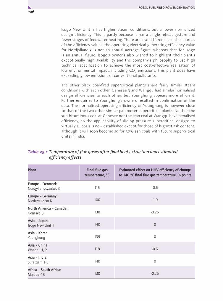
FOSSIL FUEL-FIRED POWER GENERATION 146x
Isogo New Unit 1 has higher steam conditions, but a lower normalized design efficiency. This is partly because it has a single reheat system and fewer stages of feedwater heating. There are also differences in the sources of the efficiency values: the operating electrical generating efficiency value for Nordjylland 3 is not an annual average figure, whereas that for Isogo is an annual figure. Isogo’s owner’s also wished to highlight their plant’s exceptionally high availability and the company’s philosophy to use high technical specification to achieve the most cost-effective realisation of low environmental impact, including CO2 emissions. This plant does have exceedingly low emissions of conventional pollutants.
The other black coal-fired supercritical plants share fairly similar steam conditions with each other. Genesee 3 and Wangqu had similar normalised design efficiencies to each other, but Younghung appears more efficient. Further enquiries to Younghung’s owners resulted in confirmation of the data. The normalised operating efficiency of Younghung is however close to that of the two other similar parameter supercritical plants. Neither the sub-bituminous coal at Genesee nor the lean coal at Wangqu have penalised efficiency, so the applicability of sliding pressure supercritical designs to virtually all coals is now established except for those of highest ash content, although it will soon become so for 30% ash coals with future supercritical units in India.
Table 25 • Temperature of flue gases after final heat extraction and estimated efficiency effects
Plant Final flue gas temperature, °C
Estimated effect on HHV efficiency of change to 140 °C final flue gas temperature, % points
Europe – Denmark:Nordjyllandsværket 3 115 -0.6
Europe – Germany:Niederaussem K 100 -1.0
North America – Canada:Genesee 3 130 -0.25
Asia – Japan:Isogo New Unit 1 140 0
Asia – Korea:Younghung 139 0
Asia – China:Wangqu 1, 2 118 -0.6
Asia – India:Suratgarh 1-5 140 0
Africa – South Africa:Majuba 4-6 130 -0.25

147Chapter 4 • Review of Case Studies and General Conclusions y
Niederaussem K does not reach the normalised efficiency of Nordjylland 3 or Isogo New Unit 1 although it has a complex heat recovery system. This is related to the completely different fuel quality fired there: lignite plants should really be considered separately. The fuel has a much lower calorific value than the black coals, even on a dry ash free basis, and so larger specific mass flows are needed to achieve the same amount of net power. This can be expected to increase flue gas losses and auxiliary loads. It was not possible to normalise the collected efficiency data to account for these types of effects. The important point is that Niederaussem K was pitched at using a state-of-the-art design for lignite firing, and has proven to be very successful. It represents currently operating best practice in lignite-fired power generation with respect to high efficiency through design.
Because efficiency is affected by the flue gas temperature after heat extraction, the flue gas temperatures of the case study plants after final heat extraction are shown below. Efficiency is increased by approximately 0.5 percentage points for each 20°C decrease in flue gas final temperature. Table 25 gives approximate effects of flue gas temperature changes. However, plant normalised efficiencies after such a correction are not shown, for reasons given near the beginning of this section in the introduction to Table 24.
The operating efficiencies of the base-loaded plants generally lay close to design values. Greatest deviations from design efficiency were seen for the Enfield combined cycle gas-fired plant (see Table 23 for this plant as its performance was not normalised), where capacity factor is only 40%, and Majuba, where capacity factor is lower than this, at around 32% for the dry-cooled units. Although both were built as base-load plants, fuel costs at both of these have risen – hence the low capacity factors. In the case of Majuba, the coal burnt is transported a long distance because the originally dedicated mine closed due to geological difficulties. At Suratgarh, the units operate on base load, but operating efficiency is apparently 3 percentage points lower than design. This is believed to be linked to the wide fluctuations in ambient temperatures and the different fuel properties from those originally specified.
High ash coals are used as a matter of routine in the plants in India and South Africa and the case study plants in both countries were also in areas of water shortage in both cases. Supercritical units are beginning to be built in India and these projects will gain from experience with the subcritical systems. Supercritical plants have not been ordered in South Africa to date, but are expected to be soon and will be able to gain from experience with the subcritical systems. The efficiency will be higher, but cannot be expected to equal that in locations with better coals and availability of cool water. Water shortage is becoming an important factor in many parts of the world. The South African case study plant at Majuba is in a dry area and has some dry cooled units. In China, Wangqu’s next units will be dry cooled. Efficiency and economics are unavoidably impaired by the use of dry cooling. IGCC systems use about 30% less water than PCC, so where water is available, but scarce, that might tip the balance towards IGCC, although other factors such as the negative impact of an associated high ambient temperature on gas turbine performance would need to be considered also.

FOSSIL FUEL-FIRED POWER GENERATION 148x
The natural gas-fired plant at Enfield in the UK had a much higher efficiency than any of the coal-fired units, as expected, because of the high working temperature of the combined cycle and low fuel and zero waste handling energy requirements. The gas turbine model used at Enfield is an advanced reheat machine. Developments in gas turbine and combined cycle technologies and manufacturing focused around natural gas will continue to benefit commercial offerings for turbines in coal IGCC as syngas combustion systems are further developed.
The high efficiency achieved at all the supercritical pulverised coal plants studied was helped by measures to limit internal power consumption, such as saving fan power and use of high efficiency electrical drives.
One of the most effective ways of increasing overall efficiency and so reducing CO2 emissions is to design power plants to produce both power and heat for export. Such combined heat and power (CHP) systems, also known as co-generation systems, use the low grade heat in a power plant’s steam system for district heating or industrial steam supply. Although there are limits to the extent of practical application of CHP with district heating because appropriately large heat demands are rarely available, the benefits can be large. Nordjylland 3 experience is that efficiency for power plus heat is 90% on a lower heating value basis.
Comparison of performances in the context of other coal-fired plants
The significance of these plants with respect to efficiency is illustrated in Figure 27. Here, the normalised HHV-based operating efficiencies are used, except for Wangqu (normalised design value). It shows that these represent marked improvements compared with the main body of existing thermal power stations. Such a pictorial representation is convenient to show their importance, but there are many simplifications in drawing it. In particular, the use of normalised efficiencies was only possible for the top of the world supercritical plant efficiency ranges as these coincide with two of the case study plants.
Approximate world supercritical rangeNordjylland 3
Black coal Lignite
30
35
40
45
Genesee 3Isogo New #1
YounghungWangqu (norm des)
Approximate worldsubcritical range
Niederaussem K
Approximate worldsubcritical lignite range
Approximate worldsupercritical lignite range
Netefficiency,%
HHV
Figure 27 • Normalised operating efficiencies of supercritical case study plants compared with elsewhere

149Chapter 4 • Review of Case Studies and General Conclusions y
What it does show is the dominant position of the Danish and the German units in relation to existing plants for, respectively, black coals and lignites. The need to achieve a geographical spread for the selected plants led to a clustering around 40%, HHV basis, for normalised operating efficiencies. If more Danish and some German example black coal plants had been included, there would probably have been one or two with efficiencies lying between those of Isogo New Unit 1 and Nordjylland 3.
EmissionsVirtually zero conventional emissions are possible now from PCC as well as IGCC. Isogo New Unit 1 and Nordjylland 3 show that this is possible. Innovation was very strongly shown in the technology employed at the plant in Japan. The flue gas desulphurisation system installed on Isogo New Unit 1 is a regenerable process that is now the reference plant for a multi-pollutant control system of uniquely high performance. Tailoring plant design to the requirements of the coal feed can result in high performance and low environmental impact while saving in cost. Thus, no SCR was needed at Genesee or Niederaussem, yet NOx emissions achieved are much better than regulatory requirements.
One of the other encouraging messages that has emerged from these case studies is that not only can environmental performance be designed to be very good for PCC plant, these plants in practice can perform considerably better than design. It is also notable that lower emissions of pollutants can be achieved by use of what are basically conventional environmental control systems that are now available with better performance than used to be the case. A good example is Younghung in Korea, where it was also possible to keep the investment cost low even in that OECD location.
The carbon dioxide emissions from the case study plants have been estimated or obtained from the operators and are shown in Table 26 below. The higher efficiency plants have lower emissions as less fuel is used to produce each unit of electrical power. The values estimated by IEA CCC for the coal plants were based on the calorific values and carbon contents of the fired fuels and the operating efficiencies. The natural gas-fired plant emissions are a generic estimate from UK government guidelines for UK Emissions trading. Natural gas-fired plants have the lower emissions because of their higher efficiency and a fuel containing a lower carbon content in relation to its energy content. Actual emissions will vary with fuel properties as fired. The lignite-fired Niederaussem K has higher estimated emissions than the other ultra-supercritical plants because of the additional fuel that has to be consumed to evaporate its very high proportion of moisture. With the lignite pre-drying demonstration plant operating, the emissions should decrease by around 2%, because drying 25% of the fuel will raise efficiency by one percentage point.
Because of differences in calculation methods for the values in Table 26, they cannot be used to give any more than general indications only, to illustrate the value of designing for high efficiencies in order to reduce CO2 emissions. Note particularly that emissions associated with the full fuel cycle are not included.

FOSSIL FUEL-FIRED POWER GENERATION 150x
Table 26 • Approximate specific carbon dioxide emissions, kg/MWhso
Plant Note on basis Approximate CO2 emissions, kg/MWhso
Europe – Denmark:Nordjyllandsværket 3
Data from Vattenfall over 4 years 790
Europe – Germany:Niederaussem K
Calculation by RWE 930
North America – Canada:Genesee 3
Value from EPCOR 900
Asia – Japan:Isogo New Unit 1
Value from J-POWER (rounded) 810
Asia – Korea:Younghung
Approximate estimate by IEA CCC 850
Asia – China:Wangqu 1, 2
Estimate by Doosan Babcock 830
Asia – India:Suratgarh 1-5
Approximate estimate by IEA CCC 1000
Africa – South Africa:Majuba 4-6
Calculation by Eskom (rounded) 1030
Europe – UK:Natural gas plant: Enfield
Calculation by E-ON UK based on UK DEFRA Guidelines for the Measuring and Reporting of Emissions in the UK Emissions Trading Scheme
330 for 58% LHV net efficiency;370 for 52% LHV net efficiency
Economics
Information on investment costs was supplied for virtually all plants, although the bases differed and were not always possible to define precisely despite attempts to do so. Operating costs could not be obtained from all owners. In fact, only two felt able to supply a significant part of the requested cost information. The review of operating costs is therefore based on an amalgamation of IEA CCC knowledge and indications from the data that could be collected. The operating costs are deliberately not attributed to particular plants, for reasons of fair treatment. An illustrative calculation of electricity generation cost in two general areas (OECD and non-OECD) then follows.
Capital costs
The specific capital costs in Table 23 have been converted to an approximate common basis, as far as is possible for installations in such a wide variety of locations with information in differing detail from different sources. The converted costs, shown in the fourth column of Table 27, are for overnight construction, excluding owner’s costs, for 2006. Calculations were then made

151Chapter 4 • Review of Case Studies and General Conclusions y
to allow for the cost scope (whether including owner’s costs or interest during construction) on the basis shown in the footnote to Table 27. Owner’s costs here means cost of land, clearance, initial catalysts and chemicals, start-up costs, spares, fees and working capital.
Table 27 • Treatment of specific capital cost data to arrive at indicative overnight costs
Plant and unit size
Unconverted specific capital cost, USD/kWso
Specific capital cost inflated to 2006 using US CPI*, USD/kWso
Calculated overnight specific capital cost (2006), USD/kWso**
Calculated overnight specific capital cost (2006), adjusted to plant size of 1000 MWso USD/kWso***
Steam conditionsMPa/°C/°C
Europe – Denmark:unspecified 800 MWso plant
1500 (2006) for new 800 MWeexcluding owners costs or IDC
1500 1500 1435 29/600/620
Europe – Germany:Niederaussem K (965 MWso)
1175 (2002) Total project cost
1317 1080 1072 27/580/600
North America – Canada:Genesee 3 (450 MWso)
1100 (2005)Overnight cost
1135 1135 967 25/570/570
Asia – Japan:Isogo New Unit 1 (568 MWso)
1800 (2006)Total project cost incl New Unit 2 under construction
1800 1475 1317 25/600/610
Asia – Korea:Younghung (774 MWso)
993 (2003)Basis uncertain
1088 1088 but uncertain
1034 25/566/566
Asia – China:Wangqu 1, 2 (645 MWso)
580 (2006)Overnight cost
580 580 531 24/566/566
Asia – India:Suratgarh 1-5 (227 MWso)
822 (2002)Basis uncertain
921 921 but uncertain
685 15/540/540
Africa – South Africa:Majuba 1-6 (612 MWso and 669 MWso)
410 (2001) Total project cost
467 383 350 17/540/540
Europe – United Kingdom:Natural gas plant: Enfield (372.5 MWso)
950 (1999)Total project cost
1150 958 787 -
* www.bls.gov/cpi/** assuming IDC = 13% EPC cost (coal plants), 10% EPC cost (NGCC); owner’s costs = 10% EPC cost*** exponential scalng factor of 0.8 used

FOSSIL FUEL-FIRED POWER GENERATION 152x
The above treatment brings the range of costs closer together for the supercritical and ultra-supercritical plants. Again note that the Denmark cost is not based on one of the case study plants. The highest of the adjusted specific costs are the Denmark one and the Isogo Units 1 and 2 cost. These are the most up-to-date, and their higher values likely reflect the steep rises in prices of steel and concrete that have occurred in the past two years or so because of increases in energy prices, as well rises in labour and other commodity costs. It is known that considerably higher prices are being quoted for new power projects now (over 2000 USD/kWso overnight EPC costs in OECD). The general inflator used for the other costs will not have caught these effects closely. Prevailing marketing conditions are also very important. Suppliers have to adjust their level of profit according to the competition at the time, so differences in prices paid may not necessarily reflect true cost differences. Also, if a manufacturer has the opportunity to repeat a project in more than one similar location, costs for the series of units will decrease as economies are possible in engineering and in materials procurement.
There are many other non-technical potential influences that can lie behind cost differences. One obvious one is location, in its effect on the cost of raw materials and labour required to construct a plant. The plants in non-OECD locations (Wangqu, Suratgarh and Majuba) cost the least as expected. When currency fluctuations, inflation in different zones, conventions on project cost structure and so on are added in, it is not surprising that isolating influences and identifying trends become difficult. Purchasing power parities (PPP), based on long-run exchange rates, might in principle give a more clear picture, but their use is a specialist area that was not attempted here, especially in view of the limitations of the data collected. The above considerations show that the adjusted costs have to be regarded with caution: it may even be that non-OECD plant costs could now lie closer to those in the OECD area, but this cannot be stated for certain from the data collected.
The other influences on plant cost are the technical ones. One of these is unit size. Increasing unit size is a recognised means of reducing the specific capital cost of power generation systems because it allows relative savings in quantities of materials required for equipment as larger vessel dimensions become possible. Where the electricity demand gap to be filled is expected to be high, it therefore makes commercial sense to order large systems. For a while, during the late 1980s and early 1990s, somewhat smaller units were preferred (as at Nordjyllandsværket) as non-regulated power markets were just emerging, but generally rising costs and the proven flexibility and reliability of the very large modern designs for supercritical and ultra-supercritical units has resulted in unit capacities for coal-fired units more recently reaching 1100 MWe. 500 MWe sizes are still often specified where very large increases in available capacity would be undesirable. The converted overnight costs in the fourth column of Table 27 are plotted versus plant unit size in Figure 28. For the OECD plants, this shows a fairly small cost reduction with increasing plant size and this may reflect the market pulling prices closer together. Again, note however that new projects are being quoted much higher. The costs of the non-OECD plants were significantly lower, lying on a different trend line.

153Chapter 4 • Review of Case Studies and General Conclusions y
Figure 28 • Calculated overnight specific capital cost versus unit size, coal-fired case study units in OECD locations
In Table 27, the fifth column shows the overnight specific costs adjusted to a plant size of 1000 MWso, using an exponential scaling factor of 0.8. Factors between 0.7 and 0.9 are often used to arrive at estimates of cost for different equipment areas. The value of 0.8 allows for some cost elements being linearly related to throughput. A value of 1.0 would imply linear relations for all parts of a plant, with total cost proportional to output and specific cost unaltered. The effect of adjusting to a common plant scale was to reduce the range of specific overnight costs, but the range was still quite large because plant size is only one of many technical reasons that may result in specific cost variations. For example, plant complexity in a broad sense is greater for some of these case study units than for others. Some do not have SCR units for final NOx reduction, and some have different types of desulphurisation systems, while the sub-critical plants had none. The double reheat cycle on Nordjylland 3 would affect cost, although it is emphasised here that the cost for that specific unit was not supplied for this study because of commercial sensitivity so a recent budget cost was used.
Figure 29 • Adjusted specific plant costs versus main steam temperature
0
200
400
600
800
1 000
1 200
1 400
1 600
0 200 400 600 800 1 000 1 200Unit size, MWso
Over
nigh
tspe
cific
cost
, USD
/kW
so
Genesee
Isogo Denmark
NiederaussemYounghung
OECD PLANTS
NON-OECD PLANTS
Suratgarh
Wangqu
Majuba
0
200
400
600
800
1 000
1 200
1 400
1 600
530 540 550 560 570 580 590 600 610
Over
nigh
tspe
cific
cost
,US
D/kW
sofo
r 100
0M
Wso
Main steam temperature, Co
Majuba
SuratgarhWangqu
Younghung
Genesee
Niederaussem
IsogoDenmark

FOSSIL FUEL-FIRED POWER GENERATION 154x
An earlier section in this chapter attempted to isolate the major effects on efficiency of cooling temperature and coal moisture. While being useful for illustrative purposes, it had obvious shortcomings, and similar considerations apply here to identifying technical influences on capital cost, particularly in view of the non-technical influences discussed above. Figure 29 is a plot of specific cost, adjusted as in Table 27 to a common plant size, versus main steam temperature. It shows the expected broad correlation of cost versus steam conditions, despite all the other unquantifiable components within the cost.
Figure 30 plots the normalised design efficiency data in Table 24 against the overnight specific cost, again adjusted to a common date and plant size (no cost was available for Nordjylland 3 as explained earlier so the normalised efficiency for that plant was used with the budget cost for Denmark for this curve). The indication from the plot is that, broadly speaking, designing for higher efficiencies can be expected to incur increased investment. Note also that similar considerations almost certainly apply to emissions control specifications, but it is not possible to quantify (and so separate) these influences without going into far more detail in requesting cost information than was appropriate for this set of studies.
Figure 30 • Adjusted specific plant costs versus normalised efficiency
Construction time
The construction times for the PCC units varied from 30 months to over 60 months (see Table 28). The natural gas-fired plant was quickest to construct as more of the manufacture can be done at the supplier’s premises for these types of plant. Most of the major equipment areas for coal-fired units, in contrast, have to be assembled on site. The Genesee boiler was however fast-tracked using modular construction methods, involving fitting together complete sections of floors before hoisting into place. At Wangqu, the furnace waterwalls were site assembled from shop fabricated panels. The longest time for construction was for Isogo New Unit 1. This time included removal of existing ancillary facilities for coal reception and storage and their replacement, including adding a new wharf. It was a particularly
0
200
400
600
800
1 000
1 200
1 400
1 600
35 36 37 38 39 40 41 42 43 44 45Normalised design efficiency, % HHV
Adjusted
specif iccapitalcost ,
USD/
kWso
for 1
000MWso Isogo
Younghung
Majuba
SuratgarhWangqu
Denmark
NiederaussemGenesee

155Chapter 4 • Review of Case Studies and General Conclusions y
restricted site for the lay-down and construction work, with two existing units immediately adjacent being kept running throughout. Younghung also had a long construction period. No information was available about this, but this plant is on an island site that would have required new infrastructure to be developed to enable the construction.
Table 28 • Construction time for the plants (months)
Plant Construction time per unit (months)
Europe – Denmark: Nordjyllandsværket 3 48
Europe – Germany: Niederaussem K 48
North America – Canada: Genesee 3 36
Asia – Japan: Isogo New Unit 1 66
Asia – Korea: Younghung 64
Asia – China: Wangqu 1, 2 30
Asia – India: Suratgarh 1-5 39
Africa – South Africa: Majuba 4-6 information not available
Europe – UK: Natural gas plant: Enfield 22
Operating costs
As stated at the beginning of this economics section, operating costs could not be obtained on many of the plants, so this discussion has been based on a combination of prior knowledge and indications from the data that could be collected but without indication of any individual case study plant’s costs. Very little information on operating costs could be collected from case study plants in the OECD area. In addition, the data from Asian areas (OECD and non-OECD) contained some apparently spurious values.
In addition to fuel costs, operating costs for coal-fired plants can be divided into fixed and variable components. The latter are incurred broadly in proportion to the plant operating output and time. Among the fixed costs are much of the maintenance, labour costs, rates (land taxes) and insurance. Among the variable costs are additional maintenance and raw material costs for items such as limestone for an FGD plant, cooling water, boiler feedwater make-up, chemicals and so on. Set against the variable costs are revenues from sales of by-products, where these can be realised. By-products may be ash and slag and gypsum from PCC+FGD plants and slag and sulphur from IGCC. For coal plants, the fixed costs tend to be higher than the variable costs.
During data collection, attempts were made to obtain information on many of the above cost components but the amount and quality of information that could be made available was insufficient to give more than a few indications. Some usable information on coal costs was also obtained.
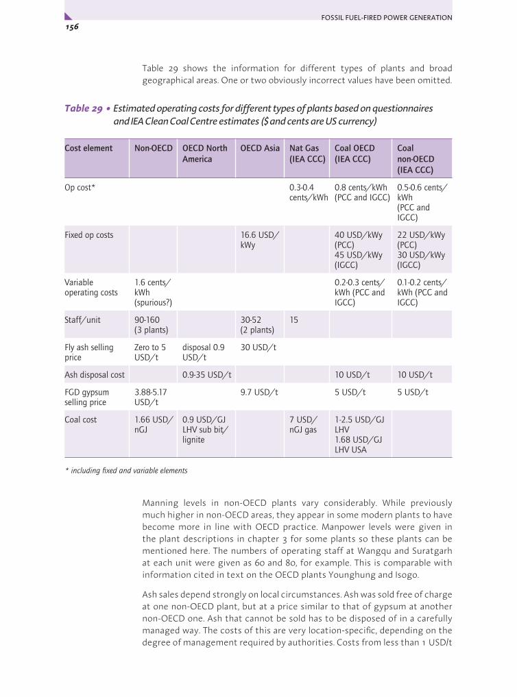
FOSSIL FUEL-FIRED POWER GENERATION 156x
Table 29 shows the information for different types of plants and broad geographical areas. One or two obviously incorrect values have been omitted.
Table 29 • Estimated operating costs for different types of plants based on questionnaires and IEA Clean Coal Centre estimates ($ and cents are US currency)
Cost element Non-OECD OECD North America
OECD Asia Nat Gas (IEA CCC)
Coal OECD (IEA CCC)
Coal non-OECD (IEA CCC)
Op cost* 0.3-0.4 cents/kWh
0.8 cents/kWh(PCC and IGCC)
0.5-0.6 cents/kWh(PCC and IGCC)
Fixed op costs 16.6 USD/kWy
40 USD/kWy (PCC)45 USD/kWy (IGCC)
22 USD/kWy (PCC)30 USD/kWy (IGCC)
Variable operating costs
1.6 cents/kWh(spurious?)
0.2-0.3 cents/kWh (PCC and IGCC)
0.1-0.2 cents/kWh (PCC and IGCC)
Staff/unit 90-160 (3 plants)
30-52 (2 plants)
15
Fly ash selling price
Zero to 5 USD/t
disposal 0.9 USD/t
30 USD/t
Ash disposal cost 0.9-35 USD/t 10 USD/t 10 USD/t
FGD gypsum selling price
3.88-5.17 USD/t
9.7 USD/t 5 USD/t 5 USD/t
Coal cost 1.66 USD/nGJ
0.9 USD/GJ LHV sub bit/lignite
7 USD/ nGJ gas
1-2.5 USD/GJ LHV1.68 USD/GJ LHV USA
* including fixed and variable elements
Manning levels in non-OECD plants vary considerably. While previously much higher in non-OECD areas, they appear in some modern plants to have become more in line with OECD practice. Manpower levels were given in the plant descriptions in chapter 3 for some plants so these plants can be mentioned here. The numbers of operating staff at Wangqu and Suratgarh at each unit were given as 60 and 80, for example. This is comparable with information cited in text on the OECD plants Younghung and Isogo.
Ash sales depend strongly on local circumstances. Ash was sold free of charge at one non-OECD plant, but at a price similar to that of gypsum at another non-OECD one. Ash that cannot be sold has to be disposed of in a carefully managed way. The costs of this are very location-specific, depending on the degree of management required by authorities. Costs from less than 1 USD/t

157Chapter 4 • Review of Case Studies and General Conclusions y
up to as high as 35 USD/t (the latter was not for one of the case study plants) have been cited. The large range arises because it may represent a marginal cost or creation of a new disposal site. In some countries, most is sold (all of Nordjylland 3 ash was sold), in others, such as the UK, around 50% is currently sold. The selling price for by-product gypsum is of the order of 3-10 USD/t in non-OECD and OECD areas. One plant in the OECD area supplied its gypsum free of charge in return for free supplies of fresh sorbent for the FGD.
Delivered coal prices in non-OECD countries are now broadly in line with coal prices in other parts of the world. For power station grade coals, this is currently in the range of 1.5-2.5 USD/GJ (LHV) (37.5-62.5 USD/t for 25 GJ/t, LHV). Some lignites and sub-bituminous coals in the USA and Canada can be delivered for around 1 USD/GJ (LHV).
Generating costs
Generating costs of a PCC plant in an OECD location have been evaluated for coal at a delivered cost of 1.68 USD/GJ, LHV (1.69 USD/mmBtu HHV) and plant overnight cost of 1165 USD/kWso. The latter was the average of the adjusted overnight costs in 2006 at 1000 MWe, for the supercritical plants in OECD locations, including the estimate from Denmark (see Table 27).
The coal cost above was based on the long term price for steam coal for electric power in the US DOE Energy Information Administration Annual Energy Outlook, 2007, reference case. A net efficiency of 45%, LHV basis (equivalent, typically to around 43.5%, HHV basis), at MCR was used to reflect a high steam parameters plant in a favourable location. Credits or penalties were not included for CO2 emissions relative to reference ceilings as both the latter and the value of CO2 are uncertain. Table 30 shows the results at a capacity factor of 80% and real discount rate of 10% with capital amortised over 25 years. The specific cost of IGCC (which also would be very site-specific and coal-type specific) is generally around 15-20% greater than that of PCC in a similar location. IGCC suppliers have plans for bringing the specific capital cost for reference designs to an initial target within 10% of that of PCC, so the table also includes IGCC 10% higher than for PCC, at 1282 USD/kWso, a higher operating cost and an efficiency also of 45%, LHV basis. These nominal figures are intended to reflect use of a new syngas-fired gas turbine in a reference plant using a dry feed gasifier.
Table 30 • Nominal generating costs – OECD location (US cents/kWh)
Supercritical PCC IGCC NGCC
Capital 2.1 2.4 1.4
O&M 0.8 0.8 0.4
Fuel 1.4 1.4 4.2
Total 4.3 4.6 6.0

FOSSIL FUEL-FIRED POWER GENERATION 158x
Table 31 shows results from a similar calculation for a non-OECD location, where the supercritical PCC plant overnight capital cost was set equal to that of Wangqu, after adjustment to 1000 MWso (531 USD/kWso). IGCC is priced at a 50% premium over PCC in this case to reflect greater foreign sourcing than for PCC (797 USD/kWso at 1000 MWso) and the same coal price was used.
Table 31 • Nominal generating costs – non-OECD location (US cents/kWh)
Supercritical PCC IGCC NGCC
Capital 1.0 1.5 1.4
O&M 0.4 0.6 0.4
Fuel 1.4 1.4 4.2
Total 2.8 3.4 6.0
Finally, a natural gas-fired system at the calculated 2006 overnight cost for Enfield at 1000 MWe (787 USD/kWso) and net efficiency of 58% (LHV) was similarly assessed and results for that are included in both the tables. It was assumed that the capital cost of NGCC would be similar in non-OECD and OECD locations as these systems can be readily packaged for supply almost anywhere. A natural gas price of 6.65 USD/GJ (LHV) (6.33 USD/mmBtu, HHV) was assumed, based on the long term price for gas for electric power in the US DOE Energy Information Administration Annual Energy Outlook, 2007, reference case. The economics of natural gas-fired plants are less favorable than they were ten years ago because of higher fuel costs, but their high efficiency, low capital requirements and short construction time mean that they will probably remain attractive to utilities as gas turbines continue to develop to higher performance. Gas prices are likely to remain well above coal prices, and more volatile in some markets. The development of the carbon market will also favour gas projects compared with coal.
The tables indicate that, assuming no carbon cost, changing energy price relativities have resulted in new coal power projects being competitive with natural gas combined cycle projects in OECD countries, while non-OECD locations favour coal more strongly over gas, arising from the lower capital requirement for coal plants there, and from the lower operating cost. The non-fuel operating costs of coal-fired systems represent a higher proportion of generating cost than is the case for natural gas-fired plants because there is no solids handling, and operating labour requirements are less for the latter. Because the capital cost component of generating costs in coal-fired systems in non-OECD areas is lower than in OECD countries, there will be a greater sensitivity to fuel price in the former. Delivered coal prices in non-OECD countries are now broadly in line with coal prices in other parts of the world.

159Chapter 4 • Review of Case Studies and General Conclusions y
Note that all economic evaluations of this type are sensitive to assumptions on discount rate, capital amortisation period, capacity factor and other aspects. They are best regarded as providing comparisons, rather than predicting absolute generating costs. Also, capital costs being quoted now (2007) for new projects are much higher than any of the data collected during this study. The impact on generating costs in Table 30 will be of the order of 1-2 US cents/kWh for coal-fired plants.
Future developments
In the near future, leading edge supercritical pulverised coal technology for use on most coal types should and will continue gradually to move to higher steam conditions, with in some cases simplification of cycles, in others, more complex systems. For example, the next BoA plants in Germany will use higher steam temperatures but a slightly higher condenser pressure and a simplified heat recovery circuit. In Denmark, at cold cooling water locations, double reheat could be adopted again, possibly in more complex form. Again, the highest steam temperatures may well be seen in Japanese designs. The current state-of-the-art for modern, sliding pressure-capable PCC boilers is 600°C main steam and 620°C reheat at the turbine. Isogo New Unit 2, now under construction, will use this. Current developments suggest that there is still scope for advanced steel alloys to be deployed for sliding pressure ultra-supercritical boilers with even higher conditions.
In other countries, there will be a follow-up move through orders for plants using increasingly high conditions while keeping just behind the state-of-the-art in order to take advantage of the experience in the most advanced plants, while minimising risk. Later, it appears likely that leading edge plant will be built in these locations also.
In some countries, such as India and China, subcritical plants will probably be built in addition to supercritical units for a while. However, local manufacturing bases for current plant are now capable of supplying supercritical technology so there will be movement toward the most advanced steam conditions.
Other countries, not yet using or building supercritical or USC technology, will probably begin orders at some point within the next few years. The UK, Australia and South Africa are examples.
Exploring new possibilities for improving PCC plant designs and minimisation of wastes will continue to be worthwhile. There are illustrations of this throughout this report, from the innovative low temperature heat recovery systems at Niederaussem to the new by-product outlet for calcium chloride from Nordjylland 3; from the regenerable SO2 removal system at Isogo, to the massive air cooling systems at Majuba.
Future developments for natural gas-fired gas turbine combined cycles will include additional machines using reheat, the development of advanced burners for ultra-low NOx emissions, use of compressor intercoolers and further new materials for higher temperatures.

FOSSIL FUEL-FIRED POWER GENERATION 160x
With the recent formation of alliances between supplier organisations, it is possible that commercial orders for IGCC will follow if the power generation utilities become familiar with reference designs and see the cost decreasing and availability improving. It is likely that incentives will still be needed for early future IGCC without CO2 capture as the technology will still be more expensive than PCC. This will be to promote market entry but should not continue once the technology is established. Most of the advances being made in NGCC technology, particularly in the gas turbines themselves, will result in benefits for IGCC. These include higher efficiency, lower NOx emissions and lower capital cost.
Future, very high temperature (700°C) boilers and steam turbines for PCC net efficiencies of over 50%, LHV basis, will need to use nickel based superalloys for some components. These are already used in gas turbines, but larger components are needed for steam boilers and turbines, and the operating environment differs. International programmes such as the EC-supported AD700 project and the associated COMTES700 demonstration in Germany are in progress to develop the materials and components for these conditions.
At some point, it looks highly likely that fossil-fired plants will need to capture and store their CO2 emissions. Both coal-fired combustion-based systems and gasification systems can be adapted, and much work is directed to such activities. Whatever method is used, CO2 capture will reduce efficiency markedly, and there will also be continuing pressure for plants to emit very low concentrations of conventional emissions, so there will be a continuing need to use innovations such as those identified in these case studies. Future 700°C PCC systems as the basis of CO2 capture plants should enable power generation efficiencies with capture to be comparable with those of current non-capture plants. Future high temperature hydrogen gas turbines and new CO2 separation methods could give IGCC with CO2 capture systems of similar performance.
General conclusions
The following points have emerged from these case studies and subsequent analyses:
y New PCC projects use S/C or USC conditions as a matter of routine to achieve high efficiency;
y USC and S/C PCC systems are available for a wide range of coal types;
y Use of new materials has been important in achieving the high efficiency and reliability;
y Complex thermodynamic cycles have evolved to enhance efficiency further;
y Heat extraction to low temperatures has been demonstrated using non-metallic components in heat exchangers;

161Chapter 4 • Review of Case Studies and General Conclusions y
y Siting helps efficiency;
y Flexibility is no longer a problem in S/C or USC;
y A wide range of coal types can be burned in PCC systems;
y The operating efficiencies of the base-loaded plants generally lay close to design values;
y Efficiency and economics are unavoidably impaired by the use of dry cooling;
y Efficiency bases vary and scrutiny is needed to avoid misleading comparisons - e.g. basis of LHV;
y Virtually zero conventional emissions are possible now from PCC as well as IGCC;
y Tailoring plant design to the requirements of the coal feed can result in high performance and low environmental impact while saving in cost – e.g. by omitting SCR;
y Environmental performance is often better than design;
y Higher efficiency plants have lower CO2 emissions;
y Combined heat and power systems have highest overall efficiencies;
y PCC specific capital costs after bringing to a common basis correlate broadly with steam parameters and with efficiency;
y Capital costs are rising for new projects (not just PCC) because of increased energy and raw material costs;
y PCC unit construction times vary considerably depending on site constraints;
y Manning levels in non-OECD plants appear in some modern plants to have become more in line with OECD practice;
y Ash sales depend strongly on local circumstances;
y The costs of ash disposal are highly location-specific and uncertain as they may represent a marginal cost or creation of a new disposal site;
y Delivered coal prices in non-OECD countries appear now to be broadly in line with coal prices in other parts of the world, in the range of 1.5-2.5 USD/GJ;
y Future PCC efficiencies of above 50%, LHV basis (approaching 50%, HHV), are envisaged within 10 years;
y IGCC could play a major role if the recent commercial offerings succeed;
y IGCC could also reach 50% efficiency, LHV basis (approaching 50%, HHV), within similar timeframe to PCC;
y Natural gas-fired CCs are more efficient and less expensive and quicker to construct than systems based on coal;
y Intrinsically high efficiency is vital as basis of future plants using CO2 capture and storage.
FOSSIL FUEL-FIRED POWER GENERATION 162x
Coal-fired power generation is essential for the next several decades but at the same time the need to limit CO2 and other emissions will intensify. Fossil fuel power plant operators must continue to explore and use means to minimise the impact of their operations, including raising efficiency of new plants and introducing even more effective environmental controls. This set of case studies on fossil power plants shows that reliable, very high performing technologies at commercially acceptable cost are in use now. They need to be even more widely deployed and further improved to meet the challenge. It is notable that innovative developments are continuing to emerge. CO2 capture will be needed before too long, and the systems for that will be built around best of today’s technologies, both combustion-based and gasification based.
Background sources
Economic History Services, Available from: http://eh.net/hmit/exchangerates/ (accessed March 2007)
Henderson C, Understanding coal-fired power plant cycles. CCC/91, London IEA Clean Coal Centre, 47 pp (October 2004)
World Energy Outlook. IEA, Paris, France, IEA/OECD (2006)
U.S. Department of Labor Bureau of Labor Statistics, Consumer price indices. Available from: www.bls.gov/cpi/ (accessed April 2007)
RWE Power Niederaussem Power Plant, A plant full of energy. RWE Power, Essen. Available from www.rwe.com, accessed November 2006 (October, 2004)
US DOE Energy Information Administration Annual Energy Outlook, 2007. Available from: http://www.eia.doe.gov/oiaf/aeo/pdf/appa.pdf (accessed April 2007)

163Appendix A • Data enquiry questionnaire y
Appendix A: DATA ENQUIRY QUESTIONNAIRE
The purpose of this questionnaire is to gather information to consider in preparing one of 8-9 case studies on recipients’ pulverised coal combustion plants. The case studies will provide a showcase of best design and operating practice in coal-fired power generation for maximum efficiency, greatest economy in costs and lowest emissions. The data will not be used for detailed performance analyses. Alternative units are acceptable.
Please also supply descriptive information on the plant configuration and systems, together with illustrative material that might be suitable for use in the report.
Plant or unit name
Owner
Boiler supplier
Turbine suppliers
Date of first operation
Technology
Design Actual
Gross power output, MWe, at MCR
Net power output, MWso, at MCR
Flexibility of output range
Auxiliary power consumption, MWe at MCR (show breakdown)
Elevation, m (Use design column)
Ambient temperature, °C
Ambient pressure, kPa
Cooling water temperature °C
Excess air level, %

FOSSIL FUEL-FIRED POWER GENERATION 164x
Coal (details below)
Coal source
Proximate analysis:
Moisture, a.r. with range
Ash, %, a.r. with range
Volatile matter, %, a.r. with range
Fixed carbon, %, a.r. with range
Ultimate analysis:
C %, daf, with range
H %, daf, with range
O%, daf, with range
N%, daf, with range
S%, daf, with range
Chlorine content, %, a.r. basis with range
Calorific value (LHV and HHV), MJ/kg, a.r. basis, with range
Hardgrove index with range
Analysis of other feedstocks, e.g. limestone for FGD
Boiler basic type (tower, two-pass) (Use design column)
Boiler efficiency (%, LHV or HHV basis)
Overall efficiency (%, LHV, sent out basis)
Recent boiler test efficiency (%, LHV or HHV) (Use actual column)
Combustion efficiency, %

165Appendix A • Data enquiry questionnaire y
Recent annual average overall efficiency (%, LHV, sent out basis)
(Use actual column)
Fuel pre-drying method, if any (Use design column)
Type of air heater (Use design column)
Air heater outlet temperature
Any special flue gas heat extraction measures (Use design column)
Flue gas temperature after all heat exchange to feedwater, °C
Furnace wall tubing arrangement (spiral, vertical) (Use design column)
Special materials in boiler tubing (Use design column)
Superheater outlet conditions, MPa/ °C
Reheater 1 outlet conditions, MPa/ °C
Reheater 2 outlet conditions, MPa/ °C (if applicable)
Superheated steam temperature control means
Reheated steam temperature control means
Features enabling high steam parameters (materials, thicknesses)
(Use design column)
Types of de-NOx systems (include any special design aspects for high performance, low power consumption, and low running costs)
(Use design column)
Type of desulphurisation system (include any special design aspects for high performance, low power consumption, and low running costs)
(Use design column)
Particulates removal system (Use design column)
NOx emissions, 6% O2, dry
SO2 emissions, 6% O2, dry
Particulates emissions, 6% O2, dry

FOSSIL FUEL-FIRED POWER GENERATION 166x
Steam turbine type, 50% reaction or impulse (Use design column)
Number of LP stages (Use design column)
Special materials in HP and IP turbines (Use design column)
Deaerator pressure, MPa
Type of cooling system (Use design column)
Condenser pressure, kPa
Number and type of LP feedwater heaters plus deaerator
(Use design column)
Number and type of HP feedwater heaters (Use design column)
Final feedwater temperature, °C
Main feed pump delivery pressure, MPa
Main boiler feed pump drive (turbine or variable speed electric)
(Use design column)
Other features contributing to high efficiency, low emissions
(Use design column)
Economic and related data:
Installation cost, USD (Use design column)
Contracting strategy – turnkey or owner design specification
(Use design column)
Construction time (notice to proceed to commissioning), months
Operating mode
Annual average capacity factor during year for quoted annual average efficiency, %
(Use actual column)
Availability in recent year (Use actual column)
Fixed operating costs, USD/kWe yr

167Appendix A • Data enquiry questionnaire y
Variable operating costs, UScents/kWhso
Fuel cost, USD/GJ with basis of CV
No of operating staff
Ash disposal cost, USD/t
Proportion of ash sold, % (Use actual column)
Selling price for ash (Use actual column)
FGD gypsum sold, % (Use actual column)
Selling price for gypsum (Use actual column)
Other features contributing to low costs


Appendix B: ACRONYMS AND ABBREVIATIONS
BHEL Bharat Heavy Electricals Ltd
BoA lignite-fired power plant with optimised engineering (German abbreviation for Braunkohlenkraftwerk mit optimierter Anlagentechnik)
BMCR boiler maximum continuous rating
CCGT combined cycle gas turbine
CCPC Canadian Clean Power Coalition
CCPI Clean Coal Power Initiative (USA)
CCT clean coal technology
CFBC circulating fluidised bed combustion
CHP combined heat and power
CO2 carbon dioxide
EPC engineering, procurement and construction
ESP electrostatic precipitator
EU European Union
EV Environmental combustor (in Alstom gas turbines)
FD Forced draught
FEED front end engineering and design
FGD flue gas desulphurisation
FGR Flue gas recirculation
GE General Electric Company (USA)
GJ gigajoule(s)
GSP Gaskombinat Schwarze Pumpe
GWe gigawatt(s), electrical
HFO heavy fuel oil
HHV higher heating value
HP high pressure
HRSG heat recovery steam generator
Hz hertz
IDC interest during construction
Appendix B • Acronyms and Abbreviations169y
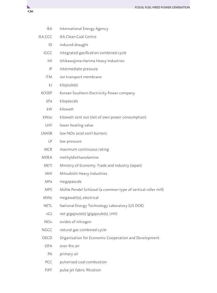
FOSSIL FUEL-FIRED POWER GENERATION 170x
IEA International Energy Agency
IEA CCC IEA Clean Coal Centre
ID induced draught
IGCC integrated gasification combined cycle
IHI Ishikawajima-Harima Heavy Industries
IP intermediate pressure
ITM ion transport membrane
kJ kilojoule(s)
KOSEP Korean Southern Electricity Power company
kPa kilopascals
kW kilowatt
kWso kilowatt sent out (net of own power consumption)
LHV lower heating value
LNASB low-NOx axial swirl burners
LP low pressure
MCR maximum continuous rating
MDEA methyldiethanolamine
METI Ministry of Economy, Trade and Industry (Japan)
MHI Mitsubishi Heavy Industries
MPa megapascals
MPS Mühle Pendel Schüssel (a common type of vertical roller mill)
MWe megawatt(s), electrical
NETL National Energy Technology Laboratory (US DOE)
nGJ net gigajoule(s) (gigajoule(s), LHV)
NOx oxides of nitrogen
NGCC natural gas combined cycle
OECD Organisation for Economic Cooperation and Development
OFA over-fire air
PA primary air
PCC pulverised coal combustion
PJFF pulse jet fabric filtration
171Appendix B • Acronyms and Abbreviations
ppm parts per million
PPP purchasing power parities
ReACT Regenerative Activated Coke Technology
ROM run-of-mine
SA secondary air
S/C supercritical
SCR selective catalytic reduction
SEV Sequential environmental combustor (in Alstom GT24/26 gas turbines)
SO2 sulphur dioxide
USC Ultra-supercritical
US DOE US Department of Energy
WEC World Energy Council
WTA fluidised bed lignite pre-drying system (German abbreviation for Wirbelschicht-Trocknung mit interner Abwärmenutzung)
y


International Energy Agency
www. i ea .o rg /books
International Energy Agency 9, rue de la Fédération 75739 Paris Cedex 15, France
CUSTOMERS IN NORTH AMERICA
Turpin Distribution The Bleachery 143 West Street, New Milford Connecticut 06776, USA Toll free: +1 (800) 456 6323 Fax: +1 (860) 350 0039 [email protected] www.turpin-distribution.com
You may also send
your order
to your nearest
OECD sales point
or use
the OECD online
services:
www.oecdbookshop.org
CUSTOMERS IN THE REST OF THE WORLD
Turpin Distribution Services ltd Stratton Business Park,
Pegasus Drive, Biggleswade, Bedfordshire SG18 8QB, UK
Tel.: +44 (0) 1767 604960 Fax: +44 (0) 1767 604640
[email protected] www.turpin-distribution.com
IEA BOOKSTel: +33 (0)1 40 57 66 90 Fax: +33 (0)1 40 57 67 75
E-mail: [email protected]
All IEA publications may be bought online on the IEA website:
You may also obtain PDFs of all IEA books at 20% discount.
Books published before January 2006 - with the exception of the statistics publications -
can be downloaded in PDF, free of charge from the IEA website.
The Online Bookshop


IEA Publications, 9, rue de la Fédération, 75739 Paris Cedex 15
Printed in France by ACTIS
(61 2007 27 1 P1) ISBN 978-92-64-03908-7
Cover design: IEA
Photo credits: © George Hammerstein/Veer – © Ryan McVay/PhotoDisc