Forwards response to IE Bulletin 79-02 re pipe support ...
171
~ 19Mjgg ENCLOSURE T ~~i ~<~t BROGANS FEKK NUCLEAR PLANT RESPONSE TO NRC-OIE BULLETIN 79-02 NRC-OIE Bulletin 79-02, issued March 8, 1979, identified four action items associated with pipe support base plate designs using concrete expansion anchor bolts for holders of construction permits and. operating licenses for nuclear power plants. The items were as follows: For pipe support base plates that use concrete expansion anchor bolts in seismic category I systems as defined by Regu1atory Guide 1.29, "Seismic Design Classification" Revision 1, dated August 1973 or as defined in the applicable FSAR. 1. Verify that pipe support base plate flexibilitywas accounted f'r in Ne calculation of anchor bolt loads. In lieu of supporting analysis justifying the assumption of rigidity, the base plates should be considered flexible if the unstiffened distance between the member welded to the plate and the edge of the base plate is greater than twice the thickness of theplate. If the base pl"te is determined to be flexible, then recalculate the bolt loads using an appropriate analysis which will account for the effects of shear-tension interaction, minimum edge distance, and proper bolt spacing. This is to be done prior to testing of anchor bolts. These calculated bolt loads are referred to hereafter as the bolt design loads. 2. Verify that the concrete expansion anchor bolts have the following minimum factor of safety between the bolt design load and the bolt ultimate capacity determined from static load tests (e.g., anchor bolt manufacturer's) which simu1ate the actual conditions o installation (i.e., type of concrete and its strength properties): a. Four - For wedge and sleeve type ichor bolts. b. Five - For shell type anchor bolts. 3. Describe the design requirements if applicable for anchor bolts to withstand cyclic loads (e.g., seismic loads and high cycle operating loads). 4. Verify from existing QC documentation that design requirements have been met for each anchor bolt in the following areas: a. Cyclic loads have been considered (c.g., anchor bolt preload is equal to or greater than bolt design load). In the case of the shell type, assure that it is not in contact with the back of the support plate prior to preload testing.
Transcript of Forwards response to IE Bulletin 79-02 re pipe support ...

~ 19Mjgg
ENCLOSURE
T ~~i~<~t
BROGANS FEKK NUCLEAR PLANT
RESPONSE TO NRC-OIE BULLETIN 79-02
NRC-OIE Bulletin 79-02, issued March 8, 1979, identified four actionitems associated with pipe support base plate designs using concreteexpansion anchor bolts for holders of construction permits and. operatinglicenses for nuclear power plants. The items were as follows:
For pipe support base plates that use concrete expansion anchor boltsin seismic category I systems as defined by Regu1atory Guide 1.29,"Seismic Design Classification" Revision 1, dated August 1973 or asdefined in the applicable FSAR.
1. Verify that pipe support base plate flexibilitywas accounted f'rin Ne calculation of anchor bolt loads. In lieu of supportinganalysis justifying the assumption of rigidity, the base platesshould be considered flexible if the unstiffened distance betweenthe member welded to the plate and the edge of the base plate isgreater than twice the thickness of theplate. If the base pl"teis determined to be flexible, then recalculate the bolt loadsusing an appropriate analysis which will account for the effectsof shear-tension interaction, minimum edge distance, and properbolt spacing. This is to be done prior to testing of anchor bolts.These calculated bolt loads are referred to hereafter as the boltdesign loads.
2. Verify that the concrete expansion anchor bolts have the followingminimum factor of safety between the bolt design load and the boltultimate capacity determined from static load tests (e.g., anchorbolt manufacturer's) which simu1ate the actual conditions o
installation (i.e., type of concrete and its strength properties):
a. Four - For wedge and sleeve type ichor bolts.
b. Five - For shell type anchor bolts.
3. Describe the design requirements if applicable for anchor bolts towithstand cyclic loads (e.g., seismic loads and high cycle operatingloads).
4. Verify from existing QC documentation that design requirements havebeen met for each anchor bolt in the following areas:
a. Cyclic loads have been considered (c.g., anchor bolt preloadis equal to or greater than bolt design load). In the caseof the shell type, assure that it is not in contact with theback of the support plate prior to preload testing.

b. Specified design size and type is, correctly installed (e.g.,proper embedment depth).
If sufficient documentation does not exist then initiate a testingprogram that wil3. assure that minimum design requ'ements havebeen met with respect to subitems a and b above. A sampling techniqueis acceptable. One acceptable technique is to randomly select andtest one anchor bolt in each base plate (i.e., some supports mayhave more than one baseplate). The test should provide verificationof subitems a and b above. If the test fails, all other bolts onthat base plate should be similarly tested. In any event, thetest program should assure that each seismic category I systemwiU. perform its intended function.
The action items are addressed on the following pages.


BROWNS FERRY NUCIZAR PLANT - NRC-OIE BULLETIN 7 -02
Action Item 1 - Flexible Plates
AU. anchor plates were assumed rigid in calculating anchor loads for B ownsFerry Nuclear Plant (BFN). A generic response (Attachment A) comparing theeffects of rigid plate assumptions is attached. At Browns Ferry a higherlevel of conservatism was applied. to the design of expansion anchors thansubsequent research indicated is necessary. This added conservation morethan offsets the maximum'5 percent underestimation of design anchor loadsindicated. in the generic response to occur by rigid analysis of flexibleplate anchorages.
To the best of our knowledge only self-drilling anchors from ITT Phillipswere used. All designs performed within TVA were based on Phillipsrecmunendations for anchor capacities in 3500 psi concrete and for limitedspacing and edge conditions (Attachment B ). Some designs performed byBergen-Patterson used wedge bolts 'based on WEJ-IT anchor capacities.
Action Item 2 - E ansion Anchor Factor of Safet
AU. moor piping systems were designed by Bergen-Patterson. In their designsa minimum safety factor of 8 was applied to self-dril1ing anchors and 4 towedge bolts. A few smaH. piping systems were designed by TVA. On thesesystems a minimum safety factor of 4 was used.
The ma5or portion of cable tray supports were designed by TVA electricalengineers. Sampling of computations indicates a variation in applied safetyfactors from 6.75 to 9.7. A smaU. number of cable tray supports weredesigned by TVA civil engineers and for those designs a minimum safetyfactor of 4 was applied for maximum load combinations.
Electrica1 support systems, instrumentation lines, battery racks etc., weredesigned by TVA civi3. engineers with a minimum safety factor of ( formaximum Wad combinations.
The above safety factors are very conservative considering that currentpractice allows increased, stress allowables or decreased factors of safetyfor maximum earthquake loadings and for other unusua1, improbable, orinfrequent loading combinations.
Action Item 3 - clic Loads Seismic and Hi h Fre uenc
Ho special design requirements were applied for seismic or for high frequencyvibrating loads. The high amplitude, low frequency, and limited cyclesassoci,ated with seismic 3.oading do not warrant special consideration.It was assumed., and has been shown, that support problems generated by highfrequency system vibrations are quickly identified. under operating conditionsand that subsequent corrections of the situationaremore critically relatedto reducing system vibrations than to corrections of anchorages. Plantoperations havebeen instructed to replace self-drilling anchors with wedgebolts wherever vibrating systems generate anchorage problems.

I %

Action Item 4 - Testin of E ansion Anchors
At Browns Ferry the anchor manufacturer's instruction for installation was
the procedure followed. Prior to August 1973 there were no testing require-ments and inspection was limited to visual determination of proper settingin accordance with manufacturer's recommendations. Routine testing ofanchors beginswith the issuance of BFN Construction Procedure No. BF-107which was based, on TVA General Construction Specification No. G-32 whichwas issued. in September 1972 (Attachment C ). For the remainder of thegob 309 tests were performed representing 2554 anchors fram various systemsthroughout all three units including reactor, turbine radwaste, dieselgenerator, and off«gas treatment buildings. With the exception of testlot number 8 only one test failure was experienced in the other 299 tests.In test lot No. 8 there appears to be a conflict between anchor size listedon the drawings and anchor size on the test report indicating the possibilitythat the 6 failures out of'0 tests were the result of testing 5/8-inchanchors for 7/8-inch proof loads.
A recent inspection of expansion anchor installations at Browns Ferry wasmade (Attachment D) by members of our design staff to evaluate installations.In general, most anchorage installations at Browns Ferry are tension typedevices for which self-drilling type anchors are best suited. The reportindicated the general condition on the anchorages to be" good. Theydid find three instances of anchorage failure which apparently resultedfrom loads being applied in directions unanticipated by design. Thesesupports will be repaired although they do not appear in any way to effectsystem operations.
In conclusion, TVA does not believe that any additional testing of anchoragesat Browns Perry is warranted in view of the overall conservations utilizedin design; the successful performance of these installations under operatingconditions, and the low incident of failure in the in-process testing whichwas performed.
'
~ ~
Generic Res onse to HRC-OIE Bulletin 7 -02
NRC-OIE Bulletin 79-02, issued March 8, 1979, identified four action itemsassociated with pipe support base plate designs using concrete expansionanchor bolts for holders of construction permits and operating licensesfor nuclear power plants. The 1tems vere as foll.ows:
For pipe support base plates that use concrete expansion anchor bolts insei.smic category I systems as defined by Regulatory Guide 1.29, "SeismicDesign Classification" Revision 1, dated August 1973 or as defined in theapplicable FSAR.
1. Verify that pipe support base plate flexibilitywas accounted for1n the calculation of anchor bolt loads. In lieu of supportinganalysis Justifying the assumption of rigidity, the base platesshould. be considered flexible if the unstiffened distance betweenthe member welded to the plate and the edge of the base plate isgreater than twice the thickness of'he plate. If the base plate1s determined to be flexible, then recalcu1ate the bolt loads usingen appropriate analysis which will account for the effects
of'hear-tensioninteraction, minimum edge distance, and proper boltspacing. This 1a to be done prior to testing of'nchor bolts.These calculated bolt loads are ref'erred, to hereafter as the boltdesign loads.
2. Verify that the concrete expansion anchor bolts have the followingminimum factor of safety between the bolt design load and. the boltultimate capacity determined. from static load testa (e,g., anchorbolt manufacturer's) which simulate the actual conditions ofinstallation (i.e., type of concrete and its strength properties):
a. Four - For wedge and sleeve type anchor bolts.
b. Five - For shell type anchor bolts.
3. Describe the design requirements if'pplicable for anchor bolts towitUstand cyclic loads (e.g., seismic loads and high cycle operatingloads).
4. Verify from existing QC documentation that design requirements havebeen met for each anchor bolt in the f'oU.owing areas:
(a) Cyclic loads have been considered (e.g., anchor bolt preloadis equal to or greater than bolt design load). In the caseof the shell type, assure that it is not in contact withthe back of the support plate prior to preload testing.
(b) Specified design size and type is correctly installed {e.g.,proper embedment depth).

If sufficient documenation does not exist, then initiate a testingprogram that will assure that minimum design requirements have beenmet with respect to subitcms (a) and (b) above. A sampling techniqueis acceptable. One acceptable technique is to randomly select and testone anchor bolt in each base plate (i.e., some supports may have morethan one base plate). The test should provide verification of subitems(a) and. (b) above. If the test fails, all other bolts on that baseplate should be similarly tested,. In any event, the test programshould assure that each seismic category I system willperform itsintended function.
The fo13.owing response addresses each of the action items generically:
GENERIC RESPONSE TO NRC-OIE BULLETIN 7 -02
Action Item 1 - Flexible Plates
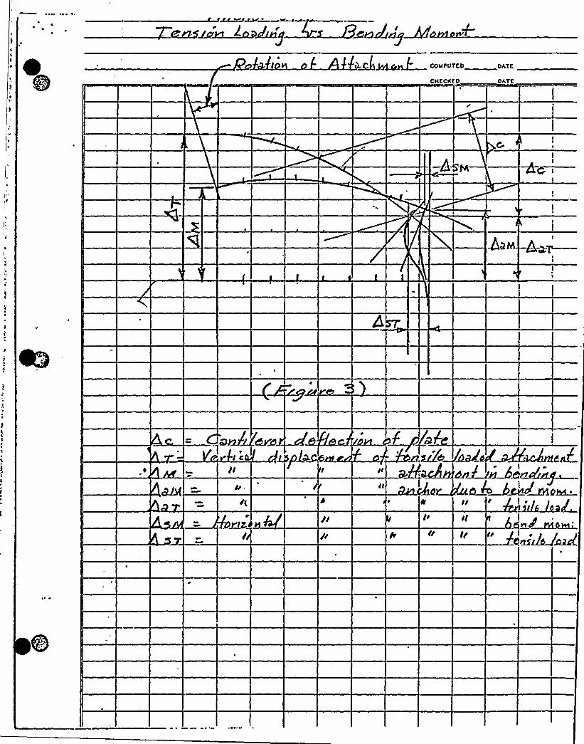
Shear-Tension Interaction - There is a distinct difference in the distribu-tion of stress in transferring load from flexible plates to anchors dependingon the method, of attachment. In bolted connections the oversize hole in theplate generally provides space for the lateral plate movement needed toaccommodate longitudinal plate deflection. When the space between bolt andplate is closed at installation or by plate movement the plate transmitsshear to the bolt through bearing on the back side of the bolt (seefigure 2). The hole oversize also provides space for rotation betweenbolt and plate effectively reducing the bending stresses in the bolt whichwould. otherwise be induced. by the rotation of the plate at the anchor.Both plate rotation and. anchor displacement are exaggerated in the attachedsketches in order to clearly demonstrate the location and dir'ection ofprincipal anchor loads. In the bolted connection "VR" is the horizontalcomponent of the resultant force of'he plate on the nut and VS is theshear induced in the bolt due to plate movement in excess of the installed.space between bolt and plate. V acts on the compression face of the boltand. can Nary in magnitude without effecting significantly the rotation ofthe bolt,. The rotation "f5" of the plate depends on the type of loadapplication as well as plate flexibility. For tensile loading (withoutbending) the plate deflects essentially as a cantilever and the maximumplate rotation at the anchor can be expressed as:
where: "e" is the distance from attachment to bolt"t" is the plate thickness"fs" is the bending stress 5n the plate"Es" is the modulus of elasticity of'teel

~ ~
Graphically (see figure 3) it can be shown that for approximately thesame anchor displacement and plate bending configuration {anchor tensilestress) that any rotation of the attachment due to applied moments willdirectly reduce plate rotation at the anchor. It also shows a reducedoverall displacement (~H versus A T) and reduced shear in the anchor{ASM versus ~ ST). Xt thus appears that for flexible plates the combined.tensile, shear, and. bending stresses in the anchor are more severe underdirect tensile loading than with attachments sub)ected to bending.
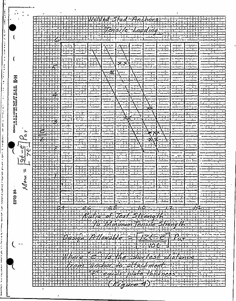
The combined stress condition in anchors is more severe in welded connectionsthan in bolted connections because there is no oversize hole to reduce shearin the anchor and maximum stresses for both shear and tension occur at thesame location as shown on the attached sketch. Results of tensile tests withwelded stud anchors attached to flexible plates are shown in figure 4.They indicate a reduced capacity for plate flexibilityof the following:
where: "e" is the shortest distance from the centerline of the anchorto the edge of the attachment"t" is the thickness of the attachment plate.
~ w
Similar tensile tests have not been performed. to date with bolted connec-tions; however, comparative performance of bolted connections and weldedconnections of cantilever attachments shoM; a distinct difference in failuretendencies at anchor stresses appxoaching or exceeding minimzn tensilestrength requirements. Mhen the angle of rotation at the anchor is large,due to plate yielding, the displacement of the anchor is a significantfactor in the ductility of the anchor and its ability to deve1op maximumtensile capacity. Anchors with large displacement capacities do not appearto be effected. by the stress combinations.
n Action - Prying action is dependent on (1) anchor displacement,2 plat rotation at the anchor, (3) plate thickness, and (4) the distance
from anchor to edge of plate. From the previous discussion and the attachedcalculations (Attachment 1), it is evident that prying action is more severein direct tensile attachments than in moment attachments. If the plate hasbeen proportioned in thickness to meet noxmal AISC allowables, and, the edgedistance is restricted to approximately two plate thicknesses or two anchordiameters then prying action willbe so small as to be inconsequential inthe calculation of anchor stress. For a given anchor displacement, platerotation, and plate thickness maximum prying action is associated with aspecific edge distance. This edge distance may be varied one to twoplate thicknesses, however, without significantly effecting prying action.
C ression Transfer - The location of the resultant compressive force ina manent connection controls the resisting moment arm of the anchorage.It is, in turn, controlled by base rotation and plate flexibility. Baserotation is affected primarily by displacement of the anchor and secondly
by plate flexibilityas long as plate stresses remain elastic. Ifplateyielding in the compression zone precedes anchor yielding then the centerof'ravity {CG) of the compressive force will shift toward the compressiveflange of the attachment. If anchor yielding, or inelastic displacement,precedes plate yielding, then the CG willmove toward the compressiveedge of the plate.
The calculations {Attachment 1) for location of the CG of the compressiveforce assume the location occurs at the point where the plate rotationbalances the rotation of the attachment without regard to any compressivedeformation of the concrete. {The confined state of the concrete willlimit compressive defoxmation in the plane of the anchorage to extremelysmsl3. values and can be conservatively ignored.)
Anchor Dis lacement - Anchor displacement is dependent on strains in theconcrete as well as in steel and on any slip characteristics associatedwith a specific type and size of expansion anchor. In the elastic stressrange the effective tensile modulus of elasticity of'nchors appears to'be less than half of the steel modulus. All expansion anchors produceplastic or inelastic concrete strains in the process of setting expansionmechanisms during installation. Inelastic strains may also occur at theheads of embedded. bolts as a result of high instaLLation torques. Thisplasticity on inelasticity does not effect the elastic displacementproperties of the anchor under load; however, because a higher load thanthe setting load. or installation torque load must occur before any additionalplastic displacement of the concrete occurs. The plastic deformationassociated with installation does however effect the amount of preloadremaining in the system. All anchor systems exhibit a short texminstallation stress loss of 25 to 30 percent during the fixst day or twofollowing installation and a permanent stress loss of approximately50 pex cent.
The strain charactexistics of the concrete during installation torque orsetting of expansion anchors are affected by the strength of concrete atinstallation, the depth of anchor head or expansion mechanism below thesurface ~and the local density of the concrete atthat point. Measurementsof torque versus anchor stress for embedded. bolts, grouted-in bolts, andwedge bolts in two distinctly different concretes clearly show that torqueand anchor load vary significantly with the concrete and anchor type(see figure 5).
Shell-type expansion anchors cannot be effectively preloaded by torquebecause the attachment plate limits the anchor displacement. For theseanchors the maximum load they see prior to service loading is theinstallation load created 'by setting the expansion mechanism. There is,therefore, considerable variation in the load producing nonlinear dis-placements with these anchors; hm~ver, the general level of service loadallowables is established to produce elastic displacements with nominalconcrete strength under service load conditions.

, I0'~
~
Wh the applied, load. exceeds the inst,a1lation setting or torque load in theanchor, then nonlinear displacement wiH. occur. The slope ofthe loa-d-
. displacement curve in the nonlinear range depends on the type of anchorand strain characteristics of the concrete.
Since anchor displacement directly affects the location of the CG of thecompression, the type of anchox has s direct effect on anchor stress. Theultimate capacity is also directly related to the displacement capacityof the anchor.
5stress in the first line of'nchors beyond the tensile flange of the attach-ment. This contrasts with load transf'er through xigid plates which producesmaximum stress in farthest line of anchors. With flexible plates, loadtransfer to the second and third lines of anchors depends on the displacementof each preceding line of anchors, the spacing of anchors, and. plate stiff'-ness. Anchor spacing is limited by anchor depth and capacity to precludefailure of the concrete. (See anchorage requirements in TVA Design StandarDS-C6.1 for Concrete Anchorages, Attachment 2.) A flexible plate analysis0 an anc 0f anchorage with more than one line of tensile anchors must balanceplate deflection at each anchor line with anchor displacemen .tAnchor e Desi - Most anchorages have essentially been designed as rigidconnections. Plate flexibilityhas generally been considered only to theextent of proportioning plate thic1messes to meet AISC stress allowables.The foU.owing comparisons have been made between xigid analysis snd,flexible analysis to determine the effect of plate flexibilityon anchorstress. Plate flexibilityhas no influence on the calculated load ofanchorages sub)ected to tensile loading without bending and, therefore,the focal.owing comparison is made for moment connections only.
In most cases anchorages are standardized to be typical for a number ofdifferent size attachments of varying cantilever spans. (Practicallyall moment connections are of the cantilever type.) Designs are,therefore, based, on maximum loading conditions and maximum attachmentsize to 4e utilized. with the typical anchorage. In this (or any othertype anchor), the concern for underestimating anchor load by rigid analysisshou1d be for the maximum attachment size corresponding to a givenanchorage configuration.
Ifboth attachment and anchorage are designed for the same loadingconditions, then the stress allowables in the anchorage should be basedon fliLLdevelopment of the attachment. If the anchor has sufficientdisplacement capacity at ultimate loading then plate flexibilitywillnot xeduce capacity and will actually increase capacity where there sretwo lines of tensile anchors beyond the attachment by allowing for equal
h displacements at both lines of anchors. Since designs are basedon service load, or factored load allowables and not on ultimate capac y,citfull development of the attachment, requires that the safety factor ofthe anchors equalsor exceedsthst of the attachment.
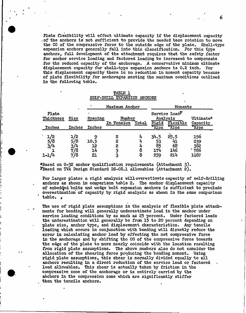
Plate f1exibility wi13. effect ultimate capacity if the displacement capacity.of the anchors is not sufficient to provide the needed base rotation to movethe CG of the compressive force to the outside edge of the plate. Shell-typeexpansion anchors generally fall into this classification. For this typeanchors, full development of the attachment requires that the safety factorfor anchor service loading, and factored loading be increased, to compensatefor the reduced. capacity of the anchorage. A conservative minimum ultimatedisplacement capacity for shell-type expansion anchors is 0.2 inch. Forthis displacement capacity there is no reduction in moment capacity becauseof plate flexibilityfor anchorages meeting the maximum conditions outlinedin the following table.
TABLE 1SELF-DRILL EXPANSION ANCHORS
Maximum Anchor Moments
PlateThickness Size
Inches
Service LoadFSp ac~in
In Tension Toaa1 ~Ri ia FIexib1e ~CanaciaInches Inches Kis Kis Kin
34.5 25.553 4185 68
174 146259 214
+Based on G-32 anchor qualification requirements (Attachment 3).Faased on TVA Design Standard DS-C6.1 allowables (Attachment 2).
1/2 1/2 9 2 4 1565/8 5/8 lo.5 2 2393/4 3/4 12 2 4 382
1 7/8 14 3 8 '861-1/4 7/8 21 3 8 1167
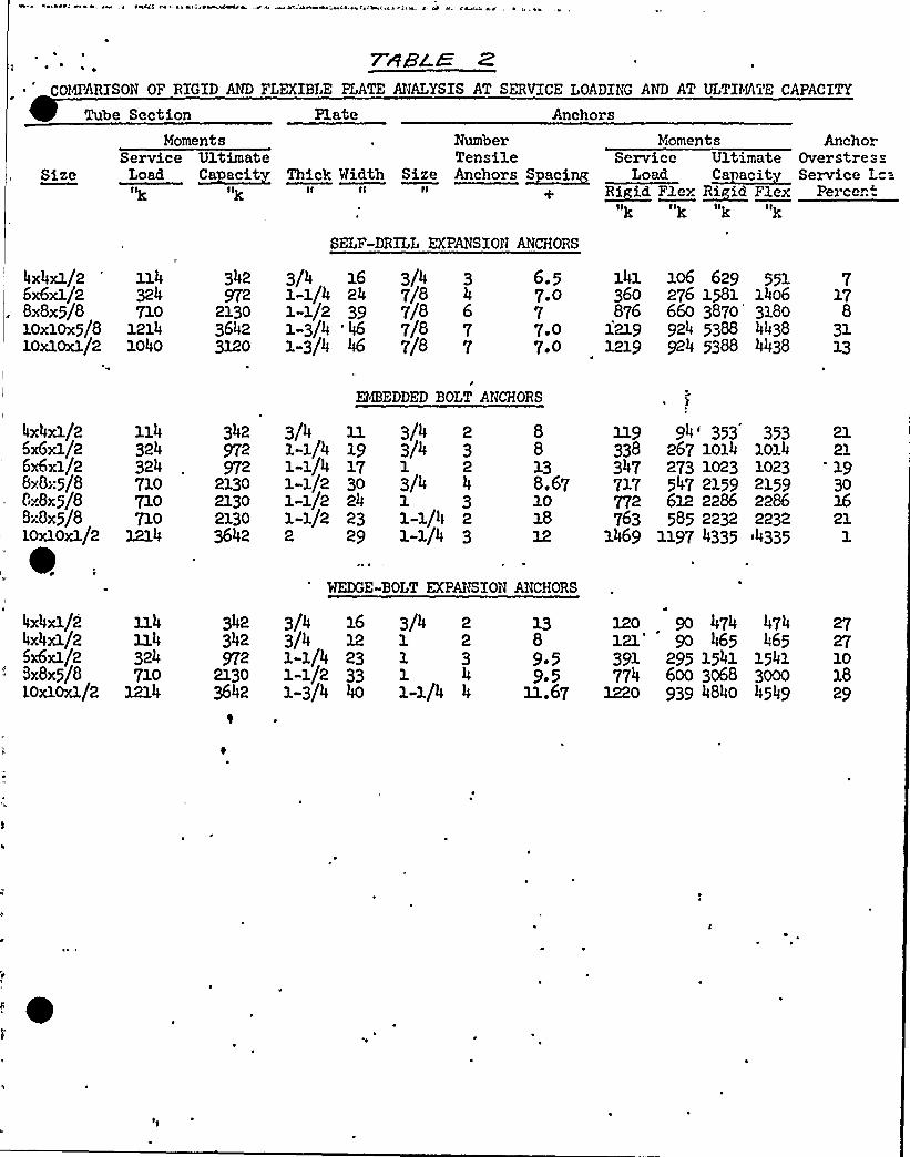
For larger plates a rigid analysis willoverestimate capacity of self-drillinganchors as shown in comparison table 2. The anchor displacement capacityof embed)ed bolts and wedge bolt expansion anchors is sufficient to precludeoverestimation of'apacity by rigid analysis as shown in the same cmgarisontable.
The use of rigid plate assumptions in the analysis of Q.exible plate attach-ments for bending will generally underestimate load in the anchor underservice loading conditions by as much as 25 percent. Under factored loadsthe underestimation will generally be fram 15 to 20 percent depending onplate size, anchor type, and displacement characteristics. Any tensileloading which occurs in con)unction with bending will directly reduce theerror in calculating anchor load by effecting the net compressive forcein the anchorage and by shifting the CG of the compressive force towardsthe edge of the plate to more nearly coincide with the location resultingfrom rigid plate assumptions. The above numbers also do not consider theallocation of the shearing force producing the bending moment. Usingx'igid plate assumptions, this shear is normally divided equally to allanchors resulting in a direct reduction of the service load or factoredload allowables. This shear is actually taken by friction in thecompressive zone of the anchorage or is entirely carried by theanchors in the compression zone which are significantly stifferthan the tensile anchors.
As long as system capacities are 1n balance 1t makes very 11ttle differencein attachment perfozmance whether anchor loads in the service load stressrange are overestimated or underestimated by the amounts indicated. Atmost, the result is a very sma11 change in system deflections or displace-ments which are of a magnitude significantly less than f'it up tolerancesnecessary for system installations. In all cases where flexible platesare used, and a close balance exists between capacities of attachment andanchorages, significant yielding of'he plate willprecede anchoragefailure and provide adequate warning afproblems. This balance is assuredby TVA's standard design allowables. The use of the relatively simplerigid plate assumptions appears to be fully justified considering theconsequences and the many f'actors affecting anchor loads.
Action Item 2 - E ansion Anchor Factor of Safet
Design allowables for expansion anchor are specified 1n TVA's Design Standardfor Concrete Anchorages DS-C6.1 (Attachment 2). Instal1ation and testingprocedures for these anchors are specified, in TVA's General ConstructionG-32 for Bolt Anchors Set in Hardened Concrete (Attachment 3). G-32requires that all expansion anchors be tested to f'ailure in job concrete.It further requires that the concrete f'r qualification testing be between3000 and 4000 psi at the time of'nstallation and testing. Each size andtype of'xpansion anchor are required. to meet minimum specified. tensilecapacities. These capacities are based on minimum f'actors of safetyapplied. to the service load, design allowables specified in DS-C6.1.If anchors of a given size and type fail to meet the required capacities,then the design allowables for those anchors at that project are reducedto maintain the minimum safety factors. For service load conditionsminimum factors of safety of 4 and. 4.g are applied to wedge«type andshell-type expansion anchors, respectively. No increase in designallowables is made for capacities in qualification testing which exceedminimum requirements and no increase in design al1owables is made forhigher strength concrete. In general, TVA's qualification requirementsare approximately 10 percent less for a given size and. embedment depthanchor than the quoted capacities of most manufacturers. Actual safetyfactors are thus generally higher than the minimum specif'ied..
A 60-percent increase in stress allowables is provided for factored loaddesign which 1ncorporates different multiplication factors (individualsafety factors) on each type of loading for various combinations of loads.Individual load factors are principally based on probability of occurrenceand accuracy of prediction. This increase i.'n stress allowables for unusualloading conditions or loading combinations is consistent with all codeapproaches.

Action Item - C clic Loads Seismic and Hi Fre uenc
System deflections are controlled by maximum anchor loads. The cycling ofloads at lower than installation load, levels willnot increase systemdeflections. System deflections will tend. to increase on cycling atmaximum anchor loads due to creep and. fatigue of concrete under highlocalized stress conditions. At loads equal to maximum design allowablesthere appears to be no problem in stabilizing deflections for thousandsof load cycles. FLexible plates appear to be beneficial in cyclic testingof anchorages by simulating springs in transferring stress reversals tothe anchors.
Anchor bolts are not subject to loosening under low frequency seismicvibrations nor is fatigue failure a likely problem because of therelatively low number of cycles involved,. No special design requirements,therefoxe, are specified for seismic loading of anchor bolts.
Bolts are subject to loosening under high frequency vibrations and fatiguefailure is dependent entirely on the level of load. variation'. If theresidual load in the anchor resulting fram installation torque exceedsthe maximum vibration 3.oad then no stress change occurs in the anchordue to vibration and. no loosening of the bolt or fatigue failure willoccur ~
Shell-type expansion anchors cannot be effectively preloaded by torqueand, torquing of the short A307 connecting bolts even to snug tightrequirements can result in failure of the installation bolts. For thisreason, the tightening of these anchors is restricted to 3./4 turn beyond.finger tight. If these anchors are toPe subject to vibration then apositive means of fastening is required. to prevent loosening.
A minimum torque is required for installation of aL1 wedge type expansionanchors.
Action Irtem 4 - In-Process Testin of Expansion AnchorsI
In-process testing of expansion anchors is specified. in TVA GeneralConstruction Specification No. G-32 which has been in force sinceSeptember 3.972. Testing frequency is specified in tems of lot sizesand, varies from a maximum rate of' test for lots consisting of lessthan 5 anchors to a minimum rate of 5 percent of the lot size for lotscontaining more than 60 anchors. For shell-type anchors a pull testproof load of 1.5 times the maximum specified. design factored load isrequired. Proof load testing of shell anchors is required prior toinstallation of attachments. Failure by slip is assumed to occur ifthe gage on the loading device indicates a drop off or lack of advance-ment of load while the anchor is being strained to the specified proof3.oad. Wedge bolt anchors are tested by torque to verify that minimuminstallation torques were applied..

The minimum embedment depths of wedge«type expansion anchors is controlledby limiting the minimum length of wedge bolts to the two longest lengthssupplied, by manufacturers and requiring in purchase specifications thatthe longer of the two lengths for each size be marked. on the ends for
'isibleidentification, Depths are then controlled by restricting theprogect1,on of'ach size bolt above the attachment plate.
Records of in-process testing are maintained at all prospects ant reportingof test results to design is required,.

ee: Ae e Oeeia e etc - e~eaae*e w x- t w wB-etc te l a. '- e- 4 e- f4 ' e e . ~
7 48'LWCOMPARISON OF RIGID AND FLEXIBLE PLATE ANALYSIS AT SERVICE LOADING AND AT ULTDfATE CAPACITY
Size
Tube SectionMoments
Service UltimateLoad ~Ca acit Thick Width SizeIk Ilk II Ii II
Anchors
Number MlomentsTensile Service UltimateAnchors ~Racing Load ~Ca acit
~RI id Flex R~iid FlexIlg II) Iig It)
AnchorOverstresService
Percen:
4x4xl/2 1146x6xl/2 324BX8x5/8 710loxlox5/8 121410xloxl/2 1040
SELF-DRILL EXPANSION ANCHORS
342 3/4 16 3/4 3 6.5 141 106 629 551 7972 1-1/4 24 7/8 4 7 0 360 276 1581 1406 17
2130 1-1/2 39 7/8 6 7 876 660 3870 3180 83642 1-3/4 '46 7/8 7 7.0 1219 924 5388 4438 313120 1-3/4 46 7/8 7 7,0 1219 924 5388 4438 13
e
EMBEDDED BOLT ANCHORS
4x4xl/25x6xl/26x6xl/2BxGx5/8tlx8x5/8Bx8x5/810xloxl/2
114324324710710710
1214
342972972
2130213021303642
3/41-1/4 191-1/4 171-1/2 301-1/2 241-1/2 232 29
3/4 23/41 23/41 3l-l/4 21-1/4
88138.67101812
119 94'53 353338 267 1014 1014347 273 1023 1023717 547 2159 2159772 612 2286 2286763 585 2232 2232
1469 1197 4335 a4335
212119301621
1
WEDGE-BOLT EXPAhSION ANCHORS
4x4xl/2 1144x4xl/2 1145x6xl/2 324Sx8x5/8 710LOxloxl/2 1214
342 3/4 16342 3/4972 l-l/4 23
2130 1-1/2 333642 1-3/4 40
3/4 21 21 3
41«1/4 4
120 9o 474 4748 121'o 465 4659.5 391 295 1541 15419.5 774 600 3068 3000
11.67 1220 939 4840 4549
2727101829


~ ~ TVA 400 A (DES SiSO)~ ~
SUBJECT
TENNESSEE VALLEY AUTHORITY
PROJECT
SHCCT
CDMI'VTL'D 0Y DATE CHCCKCD SY
7R]
, (,7 vt'r)
~~LD&D +0A'hl+C'/0gS~jg~re V
Viejg TRa
gnchnv giy)laccecnk ~y, y„g
Pvgln) For cQ
7cn~>lc goad A.o~ /he P/aleS/isur produein~ /a4v>l Ji splacavnan'k
(7 le Tu).-S odvaO Co@>zc7yoh'z
V~ibure Z )
Jggg~~ COIAPUTCD DATC
CHCCKKD DATC
I C
gl
~ ~
P '4
I! Is
~C
~ ~
~ ~
I
I
s
~ ~
~ ' I
I I
s s ~ i~ T' I ~ ~ ~
'
~ ~st ~ .'. 4
~ ~ ~I ~
I I ~ I
~ ~
~ I ~ ~ ~
I '
If ~ I
t I I ! I
I ~ ~
~ ~
f
P
~ ~
~ ~
I ~
I '
s
I ~ I
~ I ~
~ ~
I ~ ~ ~ I
~ I ~
~ 4
~ I
os))CP
oFI IC
Aj
I ~ I
I, s
I ~
~ 4 ~
s I
~ ~ ~
~ I
~ ~ ~
~ I
SvkCtl
Q
~ II ~
~ ~
C
I ~ I; ~
I ~
~ ~ II
Pit
C 4 ~ ~
P~ 4 ~
f
I
I ~ I ~
I~ t I
~ I ' ~ ~ 4~ I
I I I
~ ~
~ I
~ 1
~ s ~ ~ ~
~ ~
ID
P' I I I II ~
4 ~ ~
~ s
I ~ IC
~'
~ I ~IAIDO~Ã~ Slf~pl@p+
~ I s I '
~ ' s * II
~ I I ~ '
I I ~ s ~ IC
s
~ s '~ ~
~ II ~ ~ I
~ I ~
t~ ~ ~
~ s ~
I I ~ . ~ ~
~ I
I ~~I
~ ~ I I
4
~ )~st I
t I s
~ ~
I ~ ~ ~' I ~s ~ I I ~
csfffst. !MDEjf'J
~ ~ ~
~ ~
~ ~
~ 1I I

I
'I
0
'-S <RESS-'. REPARATION TESTS
~'
='7::=.-:. ":.":..'--R='--.-: 48ES.
K.~ SI
4
.).k;S
qA
1—8—3—4
18 . ~ggGE
8
70RQUE FT-LB
(Fjjure 5)


~ ~

r
ryg~y P/~c. rog ay O<~
~or
CHECKCO OAYC
co plltcr ohTc
i~i
~ ~ ~ II PA

CHCCKKO
W PC
ees
~ ~ ~ ~
I~ ~see J iH ' ~ ~ YL

CONCRETE ANCHORAGES
GeneralCIVIL DESIGNSTANDARD DS-C6. 1
1.0 General
1.1 This standard governs the design of steel components which transmit1
forces to concrete. Wherever possible ductility of the anchorage isassured by limiting capacities such that the failure mechanism will becontrolled by the properties of the steel rather than concrete. Whencapacities are limited by the tensile strength of the concrete, a ~orkingload safety factor of at least four is used.
1.1.1 ,,Where loads are limited by the properties of the steel, applicableprovisions of the AISC Specifications and Commentary are used.Where loads are limited by properties of the concrete, applicableprovisions of the ACI Standard Building Code are used. Anchoragesto concrete have some peculiarities which differ from the usualdesign provisions of either standard.
1.1.2 All concrete anchorages are single«shear connections involving sheartransfer through relatively large plates whose dimensions are controlledby bending'tresses, whereas the usual steel connection is a double-shear connection involving shear transfer through relatively smallplates sized for tensile loading. The effect of "long" and "short"
.-- connections and "single" or "double" shear on the shear strength ofbolts is discussed in the AISC Commentary. Research testing by TVA
- confirms the AISC Commentary recommendations for short, single-shearconnections.
1.1.3 Bearing provisions of the ACI Building Code are concerned with bear-ing restrictions on exterior concrete surfaces. Research testingclearly demonstrates those restrictions should not apply to bearingstresses at the embedded heads of anchor bolts.
1.2 Bolts with heads or nuts, or simQ.ar studs or bars, embedded in theconcrete when the concrete is placed, or grouted into holes drilledin hardened concrete, are termed standard anchors. Anchors which areexpanded laterally against the sides of a hole drilled in hardenedconcrete are termed e ansion anchors. Design load provisions of
. this standard apply only to expansion anchors listed in tables IIand III. Commercially available, predesigned and prefabricatedembedments installed prior to concrete placement and which areespecially designed for attachment of bolted connections are termedconcrete inserts. Provisions of this standard apply only to the
UNCONTROLLEDCOPY
This design standard was prepared by CEB's R&D staff in coordination withCDB's RSD staff. The requirements of this standard may be supplementedor altered for a given pro)ect by written instructions from the engineerin charge.
CPT» 9-13-76
ORIGINAI ISSUE: 9 75REVISION NO: IDATE REVISED:
CONCRETE ANCHORAGES
GeneralCIVIL DESIGNSTANDARD DS-C6.1
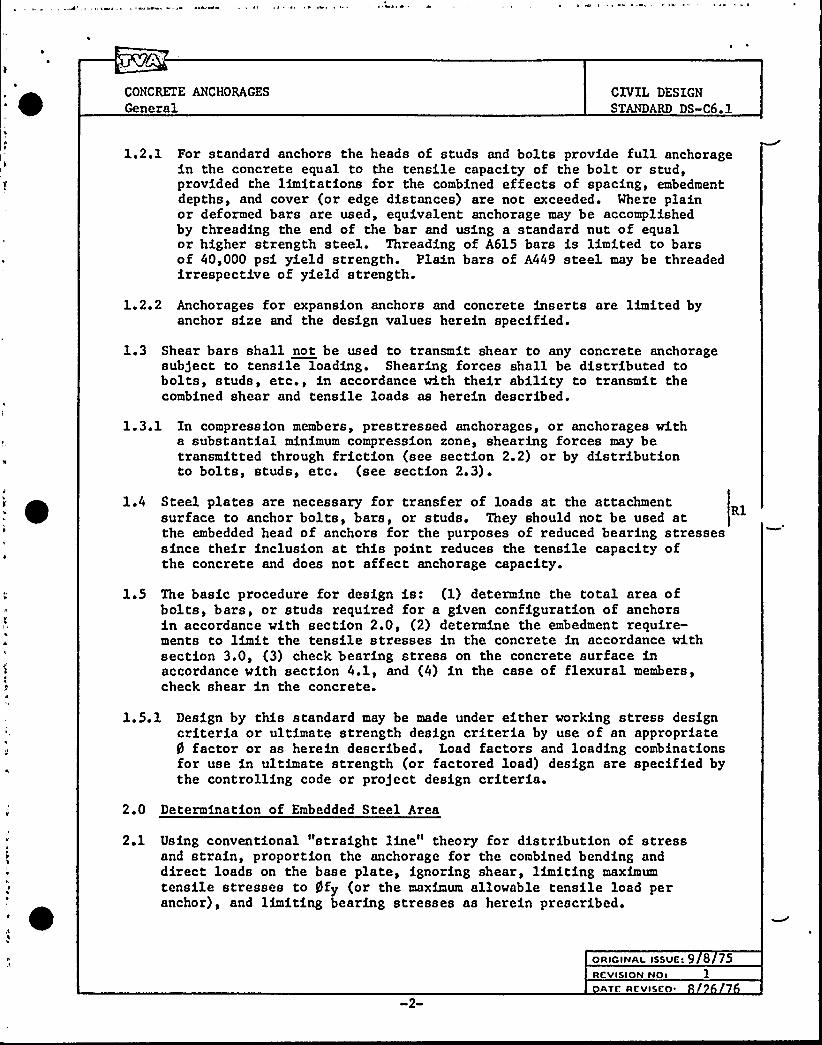
1.2.1 For standard anchors the heads of studs and bolts provide full anchoragein the concrete equal to the tensile capacity of the bolt or stud,provided the limitations for the combined effects of spacing, embedmentdepths, and cover (or edge distances) are not exceeded. Where plainor deformed bars are used, equivalent anchorage may be accomplishedby threading the end of the bar and using a standard nut of equalor higher strength steel. Threading of A615 bars is limited to barsof 40,000 psi yield strength. Plain bars of A449 steel may be threadedirrespective of yield strength.
1.2.2 Anchorages for expansion anchors and concrete inserts are limited byanchor size and the design values herein specified.
1.3 Shear bars shall not be used to transmit shear to any concrete anchoragesubject to tensile loading. Shearing forces shall be distributed tobolts, studs, etc., in accordance with their ability to transmit thecombined shear and tensile loads as herein described.
1.3.1 In compression members, prestressed anchorages, or anchorages witha substantial minimum compression zone, shearing forces may betransmitted through friction (see section 2.2) or by distributionto bolts, studs, etc. (see section 2.3).
1.4 Steel plates are necessary for transfer of loads at the attachmentsurface to anchor bolts, bars, or studs. They should not be used atthe embedded head of anchors for the purposes of reduced bearing stressessince their inclusion at this point reduces the tensile capacity ofthe concrete and does not affect anchorage capacity.
Rl
1.5 The basic procedure for design is: (1) determine the total area ofbolts, bars, or studs required for a given configuration of anchorsin accordance with section 2.0, (2) determine the embedment require-ments to limit the tensile stresses in the concrete in accordance withsection 3.0, (3) check bearing stress on the concrete surface inaccordance with section 4.1, and (4) in the case of flexural members,check shear in the concrete.
1.5.1 Design by this standard may be made under either working stress designcriteria or ultimate strength design criteria by use of an appropriate5 factor or as herein described. Load factors and loading combinationsfor use in ultimate strength (or factored load) design are specified bythe controlling code or pro)ect design criteria.
2.0 Determination of Embedded Steel Area
2.1 Using conventional "straight line" theory for distribution of stressand strain, proportion the anchorage for the combined bending anddirect loads on the base plate, ignoring shear, limiting maximumtensile stresses to gfy (or the maximum allowable tensile load peranchor), and limiting bearing stresses as herein prescribed.
OR IcINAI. IssUE: 9 8 75REVISION NO: 1

CONCRETE ANCHORAGESGeneral
CIVIL DESIGNSTANDARD DS-C6 ~ 1
2.1.1 Determine the resultant tensile load (T) in the anchorage and theresultant compressive force (Cp) under the base plate which arerequired to balance the imposed loads.
2.2 If the total shear load (V) acting in con5unction with the imposedbending and direct loads is equal to or less than 0.5 Cp for the shearplane between steel and concrete or 0.25 Cp for the shear plane betweentwo steel plates, no additional anchorage steel other than that requiredfor tensile loads is required for shear.
2.3 If the total shear load is greater than described above, determine thetotal area of embedded steel required for combined tension and shearin accordance with sections 2.3.1, 2.3.2, or 2.3.3.
2.3.1 Standard Anchors
2.3.1.1 The total area of steel required for combined tension and shear.
CV+ Tst ~f
where:
A ~ The total area of steel required. [The area of steel shallst be the stress area of threaded bolts or bars (see table Iof the Appendix) and the full cross-sectional area of weldedbars and studs.]
T ~ The total tensile load in the anchorage as a result ofcombined bending and direct load stresses.
V ~ The total shear load.
f ~ The minimum yield strength of the steel.
f ~ 33 ksi for A307 bolts.
f ~ 44 ksi for welded stud anchors (headed).y5 ~ 0.90, where V and T represent ultimate or factored loading
conditions.
9 ~ 0.55, where V and T are working loads.
C 1.10 for embedded plates with the exposed surface of thesteel plate coincidental with the concrete surface.
C ~ 1.25 for plates with recessed grout pads with the contactsurface of the plate coincidental with the concrete surface.
Rl
w3
ORIGINAL ISSUE: 9/8 75REVISION Not 1
ATE REVISEO'.

CONCRETE ANCHORAGESGeneral
CIVIL DESIGNSTANDARD DS»C6 ~ 1
C ~ 1.50 for plates fastened to hardened concrete with boltspreloaded to yield.
C 1.85 for plates supported on a pad of grout or mortar withthe contact surface of the plate exterior to the concretesurface.
Rl
2.3.1.2 Where shear is directed toward an edge, consult section 3.3 fordesign requirements.
2.3.1.3 Requirements for Tightening Standard Bolts
The following requirements for tightening bolts shall be specifiedon drawings where applicable.
(a) No standard bolted connections shall be tightened less than"snug tight." For bolts larger than 5/8-inch diameter, "snugtight" is herein described as the tightness attained by a fewimpacts of an impact wrench or the full effort of a man usingan ordinary spud wrench. For smaller bolts "snug tight" isherein described as 1/4-turn-of-the-nut after finger tighteningor after the surfaces of attachment plate and concrete are incontact.
Rl
(b) All standard bolted connections sub)ect to vibrating loadsshall be preloaded to yield by an additional 2/3-turn-of-the-nut after an initial tightening as described in (a).Where this cannot be accomplished, some positive means offastening the nut must be devised.
2.3.1.4 Sleeved connections must be completely filled with grout ormortar prior to installation of the attachment. Rl
2.3.2 Expansion Anchors
2.3.2.0 Design of expansion anchors is herein limited to the design valuesand expansion anchors listed in tables II and III. The anchorsdivide essentially into two basic types: (1) expansion shellanchors and (2) wedge bolt anchors. The design values are primarilyinfluenced by anchor size and embedment depth. The "shell" anchorsare further divided into self-drilling and predrilled types. Theanchor type and size must be specified in accordance withsection 2.3.2.5.1.
Rl
The engineer in charge may authorize the use of other types ofanchors or manufacturers other than those listed in tables II and III,provided the results of tests performed in accordance withASTM E 488-75 using concrete strengths less than 4000 psi aremore than 4 times the service load design values of tables II andIII for the same size anchor and minimum embedment depth.
4
ORII INAI ISSVC:
REVISION NO:Avc RcvIsI:o: 26 6

CONCRETE ANCHORAGESGeneral
CIVIL DESIGNSTANDARD DS-C6 ~ 1
2 '.2ol Expansion shell anchors typically fail the concrete in tensionbecause of the relatively shallow anchor depths, but failure byslip may occur at approximately the same loading. Load-deflectionmeasurements indicate a progressive splitting of the concretealong the failure cone.
Expansion wedge bolt anchors typically fail by anchor slip. Thepullout force is essentially resisted by steel-on-steel frictionof the restraining wedge. The resultant wedge pressure createstensile stresses in the concrete, and anchor slip is the resultof progressive splitting and spallage of the concrete into theopen space below the wedge. The restraint of the concrete againstsplitting is primarily a function of the location of the wedgewith respect to the concrete surface.
Tables II and III provide the allowables for tension (T) and shear(Vo) for both factored load and service load design. For anchorsspaced farther apart than the minimum spacing given, use thetabular values for To in applying section 2.1. For anchors spacedcloser than the minimums, determine To in accordance with section 3.2.
Rl
2.3.2.2 For combined loading determine the tensile load (Ti) in eachindividual anchor under section 2.1 and distribute shear to eachanchor (Vi) by:
VT To TT
Vo To
QVi> V
2.3.2.3 Where shear is directed toward an edge consult section 3.3 fordesign requirements.
2.3.2.4 Requirements for Tightening Expansion Anchor Bolts
The following requirements for tightening expansion bolts shall bespecified on the drawings.
(a) All bolt connections to "shell" type expansion anchors shall betightened by 1/4-turn»of-the-nut after finger tightening orafter the surfaces of the attachment plate and concrete arein contacts
Rl
(b) All shell type expansion anchors sub)ect to vibrating loadsmust be tightened as above and provided with a positive meansto prevent loosening by vibration.
(c) All wedge type expansion anchors shall be torqued within therange of values specified in table III unless tests performedon pro)ect concrete establish a more desirable range of valuesfor controlling deflections under service load conditions.
Rl
ORIGINAL lSSVC> 9 8 75nevis>oN No: 1
av ncvisco.

CONCRETE ANCHORAGESGeneral
CZVIL DESIGNSTANDARD DS -C6. 1
2 ~ 3. 2.5 Requirements for Testing and Designation of Expansion Anchors
2 ~ 3 ~ 2 ~ 5 ~ 1 Designation
The following letter designations shall be used on drawings andin specifications to identify the required anchor type. Theyare given in the order of descending strength requirements. Anyanchor type of higher strength requirements may be used in placeof a lower strength requirement anchor without consulting theengineer. Rl
WB
SSDSPDEA
Vedge Bolt AnchorExpansion Shell Anchor (self-drilling type)Expansion Shell Anchor (predrilled type)Unspecified type
2 ~ 3 ~ 2 ~ 5 ~ 2 Testing
(a) In nuclear plant Category I structures all expansion anchorsdesignated SSD and SPD shall require proof load testing inaccordance with General Construction Specification No. G-32.
(b) In nuclear plant Category I structures, expansion anchorsdesignated WB shall be tested in accordance with GeneralConstruction Specif ication No. G-32 ~ The installationshall be considered satisf actory if lift~ff (turn-of-the-nut) does not occur at the minimum torque specified intable III.
Rl
(c) Anchor designation EA shall only be given to "approved"anchors whose design loads do not exceed 2/3 of the minimumallowable values of table II. Proof testing is not requiredof anchors designated as EA irrespective of location.
2 ' ' Concrete Inserts
2.3.3.0 Design of concrete inserts herein designated as "standard" applyonly to continuous inserts of "Unistrut" series P 3200 channelor its equivalent.
Rl
Design of concrete inserts herein designated asonly to continuous inserts of "Unistrut" serieswith 3/8- by 4-inch long Nelson studs welded tospaced 4 inches on centers.
"heavy-duty" apply Rlchannel P 1000the channel web and
They do not apply to any other size channel or type of insert.
2.3.3.1 Failure is limited by either the steel properties of the connectingbolts or by the steel properties of the Modified "Unistrut" exceptfor slip resistance of shearing forces acting along the longitudinalaxis of the Unistrut channel.
ORIGINAL ISSUE: 8 75REVISION NO:
TE REVI EO: 26 76

CONCRETE ANCHORAGES
GeneralCIVIL DESIGNSTANDARD DS-C6 1
2.3 ~ 3 ~ 1.1 The design of "standard" inserts is limited to one single 1/2-inchbolt connection per foot of channel length.
2.3.3.1.2
For combined tensile and shear forces use the allowable tensilevalues (To) as given below in applying section 2.1 and determinethe number of 1/2-inch connecting bolts (Nb) by:
T + VN
b T V0 0
Tensile loading is limited by the strength of the channel "lip" forsin le or double bolt connections of 1/2-inch bolts preloaded to aminimum torque of 50 foot»pounds.
2.3.3.1.3
T ~ 2 kips/bolt for service loads0
T 3.6 kips/bolt for factored loads0
Tensile loading is limited by the strength of the 12-gauge metal atthe "stud" connection for ~multi le bolt connections of 3 or core1/2-inch preloaded bolts at 3-inch + spacing.
2.3.3.1.4
T ~ 5 kips/foot of channel for service loads0
T ~ 9 kips/foot of channel for factored loads0
Shear loading is limited by the shear strength of the 1/2-inchbolt in a transverse direction to the longitudinal axis of thechannel.
2.3.3.1.5
VOT 2 kips/bol t for service loads
VOT 3. 6 kips/bol t for factored loads
Shear loading is limited by the slip resistance of the preloadedconnecting bolts in the longitudinal direction of the channel.
2.3 3.1.6
V>
1 kip/bolt for service loadsOL
VOL 1 ~ 8 kip/bo1 't for fac'tol ed loads
For shear acting at any angle "5" from the longitudinal axis ofthe channel:
V —~ 2 kips/bolt for service load1OA cosS
VOA 3 ~ 6 kips/bo 1 t for factored 1 oads1.8 <OA cos
ORIGINAL ISSVtiRCVISION No:
ATE RSVI I.Ot

CONCRETE ANCHORAGESGeneral
CIVIL DESIGNSTANDARD DS-C6. 1
2.3. 3. 2 Requirements for Tightening Bolts
The following requirements for tightening bolts shall be specifiedon the drawings.
Rl
All connecting bolts for concrete inserts shall be tightened bya minimum torque load of 50-foot pounds or until a distinctyielding of the lip is detected by decreased resistance to theapplied torque.
3.0 Determination of Embedment Re uirements
3.1.0 Standard Anchors
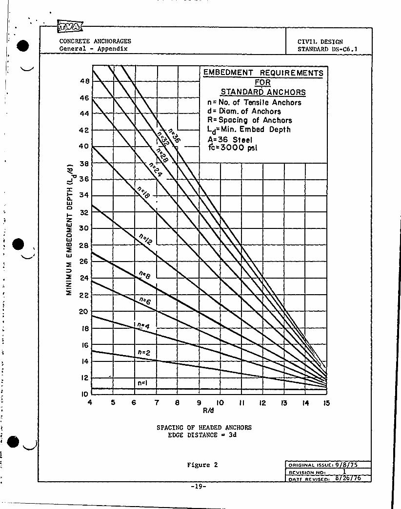
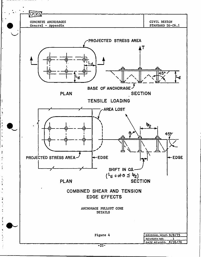
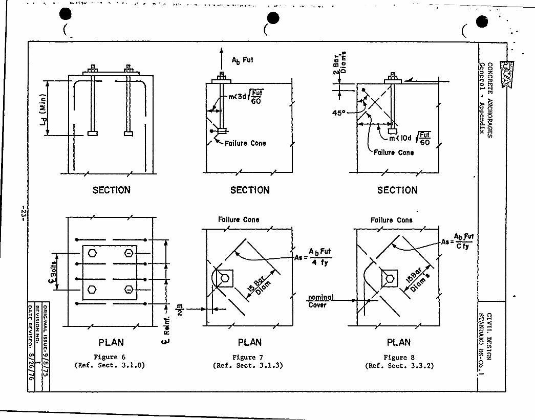
Minimum embedment lengths of bolts and bars shall be based on develop-ing 1.25 times the minimum required ultimate tensile strength of theembedded steel by assuming an allowable uniform concrete tensile stressof 3.4 ~fc acting on a pro)ected area bounded by the intersection of45-degree lines radiating from the heads of the bolts or anchors withthe surfaces of the concrete (see figure 4). When the concrete areabeyond the outside perimeter of the bolts is limited, the full tensilecapacity of the anchorage may be developed in concentrically located,fully developed reinforcing steel of equal capacity. Under no conditionsshall the lap distance between the bolt head and the mechanical anchorageor the return leg of the reinforcing bars be less than the embedmentlength requirements for the bolts without an edge condition (seefigure 6). Rl
The tensile strength of concrete in a slab or wall is limited by thethickness of the concrete and the out-to-out dimensions of the anchors.If 45-degree lines extending from the heads of exterior anchors towardthe compression face do not intersect within the concrete, then theeffective stress area is limited as shown in figure 5.
These embedment requirements may also be applied to grouted-in boltsusing either sanded Portland cement or epoxy grouts, provided thedrilled hole is approximately 2 times the bolt diameter and the sidesof the hole have been roughened and cleaned prior to grouting.
3.1.1 For bolts or anchors spaced further apart than 16 anchor diameters, theminimum embedment length (Ld) can be determined conservatively by thefollowing:
(L + m) ~ 14dFut
d 60
where:
FutL Embedded length (inches) equal to or greater than 8d
d 60'l
m ~ Edge distance (inches) equal to or greater than 3dFut60
ORIGINAL ISSUE: 8 7REVISION NO: 1
Yf REVISEO'.
CONCRETE ANCHORAGESGeneral
CIVIL DESIGNSTANDARD DS-C6.1
d Bolt diameter (inches) ~
F ~ The minimum ultimate tensile strength of the anchors in ksiut corresponding to specification requirements.
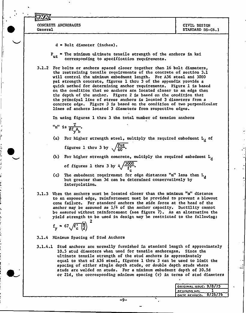
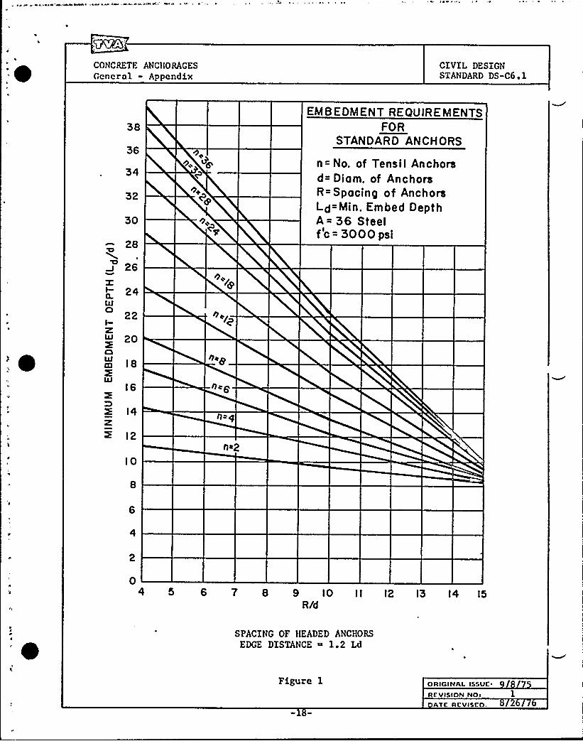
3.1.2 For bolts or anchors spaced closer together than 16 bolt diameters,the restraining tensile requirements of the concrete of section 3.1will control the minimum embedment length. For A36 steel and 3000psi strength concrete, figures 1 thru 3 of the appendix provide aquick method for determining anchor requirements. Figure 1 is basedon the condition that no anchors are located closer to an edge thanthe depth of the anchor. Figure 2 is based on the condition thatthe principal line of stress anchors is located 3 diameters from aconcrete edge. Figure 3 is based on the condition of two perpendicularlines of anchors located 3 diameters from respective edges.
In using figures 1 thru 3 the total number of tension anchors
"n" as ~~~.(a) For higher strength steel, multiply the required embedment L of
figures 1 thru 3 byFut60
(b) For higher strength concrete, multiply the required embedment Ld
of figures 1 thru 3 by 4 gf3000
c{c) The embedment requirement for edge distances "m" less than L
but greater than 3d can be determined conservatively byd
interpolation.
3.1.3 When the anchors must be located closer than the minimum "m" distanceto an exposed edge, reinforcement must be provided to prevent a blowoutcone failure. For standard anchors the side force at the head of theanchor may be assumed as 1/4 of the anchor capacity. Ductility cannotbe assured without reinforcement {see figure 7). As an alternative theyield strength to be used in design may be restricted to the following:
2
3.1.4 Minimum Spacing of Stud Anchors
3.1.4.1 Stud anchors are normally furnished in standard length of approximately10.5 stud diameters when used for tensile anchorages. Since theultimate tensile strength of the stud anchors is approximatelyequal to that of A36 steel, figures 1 thru 3 can be used to limit thespacing of either single depth studs, or double depth studs wherestuds are welded on studs. For a minimum embedment depth of 10.5dor 2ld, the corresponding minimum spacing {r) in terms of stud diameters
ORic<Naa. issue~ 9 8 75ncvisio~ ao: 1

CONCRETE ANCHORAGESGeneral
CIVIL DESIGNSTANDARD DS-C6.1
can be read directly from the figures for a given number of studs (thenumber of studs "n" should be determined as prescribed in section 3.1.2).For concrete strengths other than 3000 psi the minimum spacing can beobtained by multiplying the above spacing by
fIc
3.2 Expansion Anchors
The inclination of the concrete tensile failure angle varies with depth ofembedment for embedment depths less than 6 inches. For expansion anchorsthe assumed angle of failure g for determining the concrete tensilecapacity is given below corresponding to depth of embedment. The failure Rlsurface will be bounded by the concrete surface at which the load isapplied, and by any intersecting lateral surfaces or failure surfacesof adjacent anchors. Tensile stresses in the concrete shall be assumeduniform over this projected area and shall be limited to 2.4 ~fc forfactored loads and 1.5 ~fc for service loads. When expansion anchorsare spaced closer than the specified minimums of tables II or III, thetotal limiting tensile anchorage load must be calculated using the abovecriteria. Rl
5~28+3 ~ 4L —45d
3.3 Effect of Edge Distance on Shear Strength
3.3.1 The full strength of bolts, bars, or studs in shear can be utilizedwhen the nearest edge distance "m" is greater than 1.25 times therequired embedment "Ld" for full tensile development of standardanchors or greater than 10 diameters for expansion anchors.
m 1.25 Ld
3.3.2 Where shear is directed toward an edge located less than above,sufficient reinforcement must be provided to develop the entireshearing force and located to intersect the plane of potentialfailure (see figure 8). Limit the maximum allowable shearin the anchors such that:
(a) For an anchor spacing (r) less than edge distance "m"
U ~ 4.8 rmJf'ormax c
V 3.0 roof'ormax c
(b) For an anchor spacing
V 4.8 o ~f'or2
max'
U ~30m f'ormax C
factored loads
service loads
greater than "m"
factored loads
service loads
oRIcINaI. Issutf 8 5RCVISION NO:
V RCVISEO 8


CONCRETE ANCHORAGESGeneral
CIVIL DESIGNSTANDARD DS C6 ~ 1
4.0 Sizin of Base Plates
4.1 Allowable Bearing Stress
4.1.1 Concrete bearing stress limitations are imposed by the ACI BuildingCode to assure the integrity of both the supporting concrete andthe concrete member transmitting load. When the member applyingload is not a concrete member, then the only concern for concretestrength is the integrity of the supporting concrete.
4.1.2 When the supporting concrete is wider than the loaded area on all sides,the concrete confines the bearing area and reduces the splitting tendenciesof the supporting concrete. For building columns the provisions of theACI 318 Building Code Sections 10.14 and 11.10 apply. For all otheranchorages base plates need only be sized for the shear provisions ofSection 11.10 and as outlined below.
4.1.3 When the supporting concrete is a flexural member, then failure is eitherrestricted to a tensile concrete failure acting on a 45-degree lineradiating from the loaded area for two-way bending or a diagonaltension failure when one~ay bending controls. Bearing is thuslimited by the shear provision of Section 11.10 of the Building Code.
4.1.3.1 When bearing stress in flexural slabs or walls exceeds the above,then the shear reinforcement must be provided as outlined inSection 11.11 of the Building Code.
4.1.4 There are no bearing restrictions at the heads of standard anchorsprovided the minimum embedment requirements of section 3.0 arecomplied with.
4.1.4.1 No bearing restrictions should be applied to the sides of fullyanchored bars or bolts subject to shearing forces acting througha steel plate affixed to the bar, bolt, or stud in question.
4.1.4.2 Where anchor plates are used on the back surface of concrete, theironly function is to reduce the very high surface bearing stresswhich would otherwise occur under the head of the bolt. Theeffective distribution of stress through the anchor plate isapproximately twice the thickness of the plate beyond the headof the bolt. Anchor plates may be proportioned by assuming amaximum allowable uniform stress distribution over this areaof 6 fc>.
4.2 Special consideration should be given to the effect of large shearingforces and edge distance on the proportioning of base plates.
4.2.1 When a base plate is located near the edge of a rigid support, shear-ing forces will reduce the compressive force required to producefailure and the allowable bearing stress should be reduced. Thefollowing should be used to determine allowable bearing for a shear-ing force "V" acting toward a concrete edge:
RCVISION NO!ATE RfVIStn!
-11»

CONCRETE ANCHORAGES
GeneralCIVIL DESIGNSTANDARD DS-C6. 1
1/3 Aii 0 8 ii I 0 85V M+ 2b~a 2+2 8sb
)b' i P W 2b b
fb w O.lf'1.2f'here
A bThe area of reinforcing steel under the base plate.sb
b The base plate dimension parallel to the edge of concrete.
w ~ The base plate dimension perpendicular to the edge of concrete.
e ~ The distance from the edge of concrete to the edge of thebearing plate.
p ~ The total applied compressive load.
When the width of concrete support "Wcs
the vidth modifier —in the above2b~e2
When —w is less than e, modify the2 e+w
ia less than —,change2b~Wcsequation to —.
b
above equation by(2e+w) w
18
4a3 Where service load or working stress design is used, the allowablebearing stresses of section 4.0 should be reduced by 50 percent.
4.4 For sleeved bolts the bearing stress on the area projecting past thesleeve shall be limited to a maximum of 6fc. The minimum thicknessof the overhanging plate or washer at the base of the sleeve shall beequal to the maximum overhang.
-)2-
ORIOINaI. Issutt 9 8 75REVISION Not I
dbTE REvISEot 8 26 76

CONCRETE ANCHORAGESGeneral
CZVXL DESEGNSTANDARD DS-C6.1
NOTATIONS
A The tensile stress area of a single bolt or anchor.
A Reduced stress area for limited depth.
A » The total steel area required for anchorage.stA The area of reinforcing steel under the base plate.
sb
b The width of base plate parallel to a concrete edge.
b The width of slab or wall supporting a bearing plate.s
C The shear coefficient applied to standard anchors which accountsfor effects of cutting edges, threads, and strength factors.
iRl
C » The minimum compressive force expected to occur under the baseplate of an anchorage.
d The nominal diameter of an anchor bolt, bar, or stud.
d » The depth or thickness of a slab or wall supporting a bearing plate.B
e» The perpendicular distance from the edge of a base plate to theedge of supporting concrete.
f'he allowable average compressive stress (bearing pressure) underb a base plate.
f'he specified compressive strength of concrete.c
f » The specified minimum yield strength of steel.y
F » The minimum specified tensile strength of steel.uth» The thickness of concrete slab or wall. i Rl
L» The minimum embedded length required to fully develop the tensiled
s t reng th of an anchorage.
m The edge distance from the center of an anchor to the edge ofconcrete.
N The average dimension of the base plate divided by the depth ofslab or the thickness of wall.
N The total number of bolts in an anchorage.b
P» The maximum applied compression load on a base plate.
ORIGINAL ISSUEl 9 8 75RcvISION No: 1DATE.'EVISEDl 2

'V<~Q
CONCRETE ANCHORAGESGeneral
CIVIL DESIGNSTANDARD DS-C6.1
NOTATIONS (Continued)
r The spacing of multiple anchors.
T The total tensile force in an anchorage as a result of combinedbending and direct load stresses.
T The tensile force in an individual anchor.
T The maximum tensile force allowed in an individual anchor.0
U The total shear in an anchorage.
V , V The maximum shear value of an individual anchor without edgeeffects.
V ~ The shearing force acting on an individual anchor.iV The shearing force acting on any angle "9" from the longitudinal
OA axis of an insert.
VO The shearing force acting along the longitudinal axis of an insert.
VOT The shearing force acting perpendicular to the longitudinal axisof an insert.
M ~ The base plate dimension perpendicular to the edge of concrete.
Mes
~ The width of concrete support.
~ The capacity reduction factor, normally taken as 0.9 for factored )Rlload design and 0.55 for service load design. Also used todesignate the angle of applied load.
-14-
ORIGINAL ISSUEI 8 75REVISION NOR 1
T REVI EO:

CONCREZE ANCHORAGESGeneral - Appendix
CIVIL DESIGNSTANDARD DS-C6.1
TABLE ISTRESS AREAS OF TKUM)ED BOLTS
(UNC Thread Series)
BoltDiameterInches
1/4
5/16
3/8
1/2
5/8
3/4
7/8
1-1/8
1-1/4
1-3/8
Net Area(ASN)
S . Inches
0.032
0.052
0.078
0.142
0.226
0.334
0.462
0.606
0 '630.969
1.16
BoltDiameter
Inches
1-1/2
1-3/4
2-1/4
2-1/2
2-3/4
3-1/4
3-1/2
3-3/4
Net Area(ASN)
ScC. Inches
1 ~ 41
1.90
2.50
3.25
4.00
4.93
5.97
7.10
8.33
9.66
ORICINAL ISSUE: 8REVISION Nos lo TE REvISEO. 8 26 76

) ) ) Er ) ~ < J( l . ) r, ), )o)))or ~ ~ r
TABLE IIEXPANSION SHELL ANCHOR DATA
Bolt Sizein.
MinimumDepth
in.T
0V0
FactoredLoad Design
ki sV
0T
0
ServiceLoad Design
ki s
NominalMinimum Spacing
in.
1/4
5/16
1-3/32
1-5/16
0.70 0.50 0.45 0.30
1.05 0.80 0.65 0.50
2.5
3.5 ACCEPTABLE SSD ANCHORS
3/8
1/2
5/8
2-1/32 2.30 2.20 1.45 1.40
2-15/32 3.10 3.55 1.95 2.25
1-17/32 1.50 1.25 0.95 0.80 4.0
5.0
5.5
Phillips Self-DrillRawl Self-Drill
ACCEPTABLE SPD ANCHORS
3/4 3-1/4 4.40 5.25 2.75 3.30 6.5Phillips Non-DrillRawl Steel Drop-inHilti Hol Hugger
7/8 3-11/16 5.30 7.20 3.30 4.50 7.0
bPl(
Pl
0( Z
z0
NOTES: (a) Allowable loads shown above apply only to anchors which are to be proof tested inaccordance with Standard Construction Specification No. G-32.Use two-thirds of the above values in design of anchors which are not to be proof tested.
(b) Allowable loads apply only for anchors in concrete having a compressive strengthof 3000 psi or more.
(c) Allo~able loads are for predrilled (SPD) anchors. For self-drilled (SSD) anchorsthe above values for T may be increased by 20 percent.
0M
MQ


8 0 00 0pn „, 0' 0 0 0 0y
TABLE IIIWEDGE BOLT DESIGN DATA
BoltSize
in0D
Min.Length
in.
1Min.Depth
Ld
2Max0
AttachmentThickness
in.T
0V
0
FactoredLoad Design
ki s
ServiceLoad Design
ki sV
0
Min.Spacing
InstallationTorque
ft.-lbsMin. Max.
1/2 5-1/2 3-1/4 1-1/2
5/8 6 4-1/4 7/8
3/4 8-1/2 6 1-3/4
1 9 7 1
1-1/4 12 9 1-3/4
3.35 3.20
4.40 4.80
6.60 6.65
10.00 10.70
13.10 15.60
1/4 3 1-3/4 1 0.95 0.80
3/8 3-1/2 2-1/4 7/8 1.45 1.90
0.60 0.50
0.90 1.20
2.10 2.00
2.75 3.00
4.20 4.15
6.30 6.70
8.20 9.75
3.0
4.0
5.0
70
9 5
10.5
15
40
70
120
240
400
10
30
60
100
180
360
500
NOTES: (1) Depth measured to the bottom of the anchor.
(2) Longer bolts which are required for thicker attachments must be color coded for identity.
(3) Maximum projection of the bolt above the attachment after installation should not exceedtwo bolt diameters.
(4) Allowable loads are based on concrete having a minimum compressive strength of 3000 psi.
APP ROVED ANCHORS
HiltiKwik BoltPhillips Wedge AnchorRawl Stud BoltWe)-It

CONCRETF. ANC)IORAGESGeneral - Appendix
CIVIL DESIGNSTANDARD DS-C6 F 1
38
36
SO
28
26
I- 24
22I-w 20C)
a) I 8LLI
16
E I4Z
I2
IO
nap
nc6
h+2
EMBEDMENT REQUIREMENTSFOR
STANDARD ANCHORS
n= No. of Tensil Anchorsd= Diam. of AnchorsR= Spacing of AnchorsLd = Min. Embed DepthA= 36 Steelf'c = 3000 psl
04 5 6 7 8 9 IO II I2 IS I4 I5
R/d
SPACING OF HEADED ANCHORSEDGE DISTANCE ~ 1.2 Ld
Figure 1 ORIGINAL ISSUE
RE'VISION NO:ATE RCVISCO,
CONCRETE ANCHORAGESGeneral - Appendix
CIVI1. DESIGNSTANDARD DS-C6.1
48
46
40
38
36
34
CI32
304J
28
26
24
22
20
n,0/
h g
0„
Cp
EMBEDMENT REQUIR E MENTSFOR
STA N DARD AN C HORSn= No. of Tensile Anchorsd= Diom. of AnchorsR= Spocing of AnchorsLd=Min. Embed DepthA=36 Steelfc< 5000 psi
l8
l6
l2
l04 5 6 7 8 9 l0 l l l2 I3 14 15
R/d
SPACING OF HEADED ANCHORS
EDGE DISTANCE ~ 3d
Figure 2
-19-
oa<c>aaL. assur. 9 8 75acvisio~ rvo: 1
AT RfVISEo.

CONuu;.TE ANCHORAGESGeneral - Appendix
CIVIL DESIGNSTANDARD DS-C6.1
70
66
62
&54
+ SOLLJCl
46zo 42
5S
30
O~
Qp
C~
n+/y
noe
EMBEDMENT REQUIREMENTSFOR
STAN DARD ANCHORS
n= No. of Tensile Anchorsd= Diam. of Pn chorsR* Spacing of AnchorsLd Min. Embed DepthA=36 Steelfc*5000 psi
26
22
IS
I4
IO4 5 6 7 S 9 IO I I I2 13 I4 l5 16
RAI
SPACING OF HEADED ANCHORS
EDGE DISTANCE ~ 3dTWO PERPENDICULAR EDGES
Figure 3 ORIGINAL ISSUE: 8 75REVISION NO:
AT R vISEo. 8 6 76

CONCRETE ANCHORAGESGeneral - A endix
CIVIL DESIGNSTANDARD DS-C6.1
PROJECTED STRESS AREA
PLAN
Ld
BABE OFANCMORAGE~SECTION
TENSILE LOADING
AREA LOST
454
PROJECTED STRESS AREA
IIrEDGE EDGE
PLAN
SHIFT IN CQ.
(Ld c*8 (Vp}
SECTION
COMBINED SHEAR AND TENSIONEDGE EFFECTS
ANCHORAGE PULLOUT CONE
DETAILS
Figure 4
-21-
ORICINAL ISSUE:
RCVISION NO:AT RE'VISEO: 8


CONCRETE ANCHORAGESGeneral - Appendix
CIVIL DESIGNSTANDARD DS-C6.1
% EFFECTIVE STRESSAREA
EFFECTIVESTRESSAREA
'b
(brag-ah)
PLAN
QB
EFFECTIVE STRESSAREA
UP
LdA A,
(a+ay-ah)
EFFECTIVE STRESS AREA
A-A
STRESS AREA REDUCTION FOR LIMITED DEPTH (A )
AR (a + 2Ld - 2h) (b + 2Ld - 2h)
*REDUCE BY THE TOTAL BEARING AREA OF THE ANCHOR
STEEL
Figure 5
.-22-
oRIGINAL IssUe: 9 8 75ReVISION NO: 1
A RKVISFOS
s = si s $ %" i' i r - „~I ~ ~ M I I = i
Ab FuteL
~ D
m<3dP6045o
Failure ConeC lod 60
Failure Cone
SECTION SECT) ON SECTtON
Failure Cone Failure Cone
0 B AbFufAs=—4 fy
AbfutAa=-Cfy
0 O N pXa~
nominaCover
PLAN
Figure 6(Ref. Sect. 3.1.0)
PLAN
Figure 7(Ref. Sect. 3.1.3)
PLAN
Figure 8(Ref. Sect. 3.3.2)

TENNESSEE VALLEYAUTHORITYDIVISION OF ENGINEERING DESIGN
GENERAL
CONSTRUCTION SPECIFICATIONNO. G-3a
FOR BOLT ANCHORS SET XN HARIElKD CONCRETE
@Oggmg
cov~
REVISION 0 Rl R2 R4 R5
Date
SPONSORED
SUBMITTED
RECOMMENDED(Sponsor Branch Chief)
CONCURRED
SPEC. SECTION
APPROVED{Dir.of Construction)APPROVEO{Oir.of En . Osgn.)
September 1972Ori nal Si ed b
R. E, BullockO. H. RaineC ~ H, Glam
F, P. Lacy
P. L. Duncan
H. H. Hull
J. R. Parrieh
3-28-75Initiale
OHR
9-23-75 4"21-76
Prn/.
7-21-77
'Wc.
TVA t 0574A (DED 8.74)


GENERAL CONSTRUCTION SPECIFICATION FORBOLT ANCHORS SET IN HARDENED CONCRETETitle:
REVlSJON LOGG-32
RevisionNo. DESCRlPTlON OF REVlSlON Date
Approved
Revised DED organization names and revised sections 1.2, 6.1,and 6.2 to clarify project office drawings and reportingrequirements.
10-73
Revised sections 1.5, 2.1, 2.3, 3.2, 3.3, 4.0, and 5.2 fordetails. Revised section 6.1 to send reports to appropriateDesign Project Manager. Added section 3.5. Made new coversheet. Added revision log.
3-75
Revised section 3.2 to eliminate the use of epoxy grout in firehazard areas. Revised section 6.1 to require transmittal ofanchor test reports to DED for only those anchor lots in whichan anchor fails when tested. Revised section 6.2 accordingly.Added Attachment A.
9"75
Revised sections 1.2, 1.5, 4.2, and 6.2 to reduce requirementsof testing expansion anchors and reporting; section 4.3 toclarify concrete strength for expansion anchors.
4-21-76
General revision to add wedge bolt anchors, nondrilling expansionshell anchors, qualification tests on all types of expansionanchors, and to modify other sections accordingly. Only thesignificant changes for this revision are noted by revisionindications on the pages; previous revision indications aredeleted. Removed Attachment A.
7-21-77
TVA )0534 (OED 9 73)

0

GENERAL CONSTRUCTION SPECIFICATION FORBOLT ANCHORS SET IN HARDF.
TABLE OF CONTENTS
Revision Log .
~Pa e No.
1.0 GENERAL ~ ~ ~ ~ ~ ~ ~ ~ ~ ~ ~ ~ ~ ~ a
la 1 ~Sco e ~ ~ ~ ~ ~ ~ ~ ~ ~ ~
1.2 D~eaeia a
1.4 Reference S ecifications1.5 Definitions
1"1l«l1".11"11-2
2.0 MATERIALS ~ ~ ~ ~ ~ ~ ~ ~ ~ ~ ~ 2-1
3.0
2.1 E ansion Shell Anchors2.2 Wed e Bolt Anchors2.3 Drill Bits2.4 Bolts2.5 Portland Cement Grout2.6 D -Pack Mortar
2.8 ualification of E ansion
INSTALLATION
~ ~ ~ ~
Anchors
2"12-12-12-22-22-22-32-3
3-1
I>l~
4.0
5.0
3.1 General3.2 E ansion Shell Anchors3.3 Wed e Bolt Anchors3.4 Grouted Anchors3.5 Iocation .3.6 Reinforcin Steel3.7 E uivalent Anchors
TESTS ~ ~ ~ ~ ~ ~ ~ ~ ~ ~ ~
4.1 Selection4.2 Ex ansion Shell Anchors4.3 Wed e Bolt Anchors
REPLACEMENT
3-13-13-13-33-43-53"6
4-1
4-14-14-2
5-1
5.1 General5.2 Removin Anchors
5-15-1
TVA 10535 (EN DES 5-77)

GENERAL CONSTRUCTION SPECIFICATION FORBOLT ANCHORS SET IN A E
TABLE OF CONTENTS (Continued)
6.0 RECORDS AND REPORTS
6.1 General
~Pa e Ne
6-1
6-16-1
A~endix A "QUALIPICATION TESTS FOR EXPANSION SHELL ANCHORS"
A~endix B "QUALIFICATIONTESTS FOR WEDGE BOLT ANCHORS"
A-1
B-1


GENERAL CONSTRUCTION SPECIFICATION FORBOLT ANCHORS SET IN HARDENED CONCRETE G" 2
1. 0 GENERAL
1.1 ~Sco e
This specification prescribes materials and methods for settingthreaded anchoring devices for equipment and fixtures intoconcrete which has previously hardened. The work includesqualification of anchors, anchor installation procedures, andtesting of anchors installed in nuclear plant category Istructures.
1.2 ~Drawin s
Anchors shall be provided according to drawings prepared by orapproved by the Division of Engineering Design (EN DES). Changes Ishall be made only with the approval of the Engineer.
The Division of Construction (CONST) project office shall preparedrawings, or mark half-size prints of drawings prepared by orapproved by EN DES; to show the location of and test informationon each lot of anchors which require testing. Drawings willnot be required where another system which uniquely and completelydefines a lot is adopted and recorded with test information.
The Engineer as used in this specification shall mean theauthorized representatives of the Manager of Engineering Designand Construction. For design considerations, these shall bethe Division of Engineering Design acting through the appropriateDesign Project Manager or Engineering and Design Branch Chief.For construction, in general, these shall be jointly the appropriateDesign Project Manager or Engineering and Design Branch Chiefand the project Construction Engineer or their designatedrepresentatives; any deviation from this specification must beagreed to jointly by them.
1.4 Reference S ecifications
The latest revisions of the following specifications shall applywhere referred to in this specification.
TVA 10535 (EN DES-5.77) ADCON - PN-025

GENERAL CONSTRUCTION SPECIFICATION FORBOIT ANCHORS SET IN H RDFNFD C NC
1.0 GENERAL (Continued)
1.4 Reference S ecifications (Continued)
American Societ for Testin and Materials
A 36 - Standard Specification for Structural Steel
A 307 - Low-Carbon Steel Externally and Internally ThreadedStandard Fasteners
C 109 - Standard Method of Test for Compressive Strength of HydraulicCement Mortars (Using 2-in. or 50-mm cube specimens)
C 144 - Standard Specification for Aggregate for Masonry Mortar
E 4SS - Standard Test Methods for Strength of Anchors in Concreteand Masonry Elements
Tennessee Valle Authorit
General Construction Specification No. G-2 for Plain and ReinforcedConcrete (hereinafter termed G-2)
Civil Design Standard DS-C6.1, Concrete Anchorages (hereinaftertermed Design Standard)
1.5 Definitions
Vherever the words defined below appear in this specification, theyshall have the meanings here given.
Attachment. A piece of equipment or fixture to be fastened tohardened concrete.
Anchor. A threaded device for fastening attachments to hardenedconcrete (distinguished herein as expansion anchors and groutedanchors).
Ex ansion Anchor. An anchor which expands laterally in a drilledhole to resist pullout.
Ex ansion Shell Anchor. An expansion anchor which consistsof an internally threaded, externally slit tubular shellwith a single cone expander that causes the shell to expandlaterally against the sides of a drilled hole.
Self-drillin Ex ansion Shell Anchor. An expansionshell anchor which uses the shell for drilling thehole (designated herein an~ on the drawings as SSD).
1-2

GENERAL CONSTRUCTION SPECIFICATION FORBOLT ANCH S S
1.0 GENERAL (Continued)
1.5 Definitions (Continued)
Nondrillin E ansion Shell Anchor. An expansionshell anchor which is placed in a predrilled hole(designated herein and on the drawings as SPD).
Wed e Bolt Anchor. An expansion anchor which consists ofan externally threaded bolt with a split ring or separatewedge pairs that expand laterally against the sides of apredrilled hole when the bolt is torqued, and which willexpand further if the bolt is partially extracted from thehole by a tensile load (designated herein and on the drawingsas WB).
Grouted Anchor. An anchor which consists of a headed bolt ora threaded rod with an end nut, placed in a drilled hole, theremainder of which is filled with grout or dry-pack mortar.
~Cate o I. Nuclear plant equipment and structures so classifiedin the plant Safety Analysis Report. (Category I is class I innuclear plants under construction at the time of original issueof this specification.)
Lot. A number of anchors in a nuclear plant category I structurewhich are considered as a group for testing purposes. A lotshall consist of the anchors installed by a specific crew eitherin a specific location in the plant or over a period of time.If the lot is defined on the basis of anchor location, the lotshall consist of: (a) the anchors for a single piece of equipmenthaving three or more anchors, (b) the anchors on a floor, wall,or ceiling which has conveniently indicated boundaries, or (c)a long line of anchors on a floor, wall, or ceiling for acontinuous structure such as a cable tray. If a lot is definedon the basis of anchors installed over a time period, the maximumtime period shall be 2 weeks, each crew shall apply a uniqueidentification mark on the concrete adjacent to the anchor orto a piece of equipment with more than one anchor, and arecord of all anchor installations shall be kept. Regardlessof the basis for defining the lot, anchors of a different typeor brand shall be considered in separate lots and sufficientrecords shall be kept to ensure that all anchors are assignedto a lot.
~Sli . During testing, an expansion shell anchor shall beconsidered to have exhibited slip if the gage on the loadingdevice indicates a dropoff or lack of advancement of load whilethe anchor is being strained.
1-3
TVA 10535 (EN DES.5-77)


GENERAL CONSTRUCTION SPECIFICATION FORBOLT ANCHORS SET IN HARDENED CONCRETE G- 2
1.0 GENERAL (Continued)
1.5 Definitions (Continued)
A roved Permitted Re uired. Wherever such words are used inthis specification, they shall be held to refer to the ordersor instructions of the Engineer unless another meaning is plainlyintended.
Called For. Wherever these words are used in this specification,they shall mean called for by drawings, memorandums, or separatespecifications issued by the Division of Engineering Design.
1-4

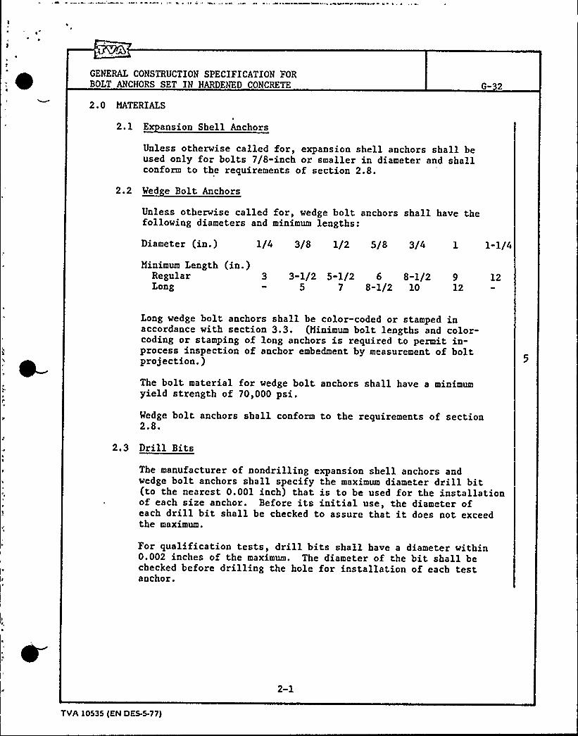
GENERAL CONSTRUCTION SPECIFICATION FORBOLT ANCHORS SET IN HARDENED CONCRETE
2.0 MATERIALS
2.1 E ansion Shell Anchors
G- 2
Unless otherwise called for, expansion shell anchors shall beused only for bolts 7/8-inch or smaller in diameter and shallconform to the requirements of section 2.8.
2.2 Wed e Bolt Anchors
Unless otherwise called for, wedge bolt anchors shall have thefollowing diameters and minimum lengths:
Diameter (in.) 1/4 3/8 1/2 5/8 3/4 1 l-l/4Minimum Length (in.)
Regular 3Long
3-1/2 5-1/2 6 8-1/25 7 8"1/2 10
9 1212
Long wedge bolt anchors shall be color-coded or stamped inaccordance with section 3.3. (Minimum bolt lengths and color-coding or stamping of long anchors is required to permit in-process inspection of anchor embedment by measurement of boltprojection.)
The bolt material for wedge bolt anchors shall have a minimumyield strength of 70,000 psi.
Wedge bolt anchors shall conform to the requirements of section2.8.
2.3 Drill Bits
The manufacturer of nondrilling expansion shell anchors andwedge bolt anchors shall specify the maximum diameter drill bit(to the nearest 0.001 inch) that is to be used for the installationof each size anchor. Before its initial use, the diameter ofeach drill bit shall be checked to assure that it does not exceedthe maximum.
For qualification tests, drill bits shall have a diameter within0.002 inches of the maximum. The diameter of the bit shall bechecked before drilling the hole for installation of each testanchor.
2-1
TVA 10535 (EN DES.5.77)
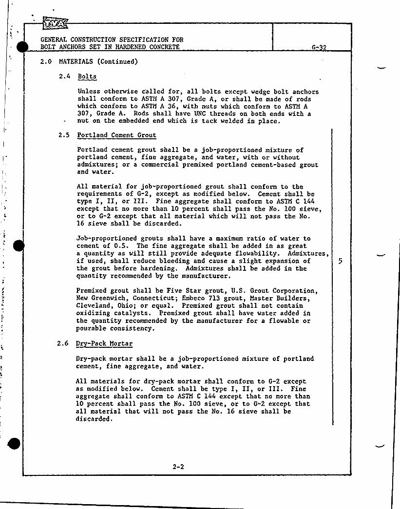
GENERAL CONSTRUCTION SPECIFICATION FORBOIT ANCHORS SET IN HARDENED CONCRETE
2.0 MATERIALS (Continued)
2.4 Bolts
Unless otherwise c'alled for, all bolts except wedge bolt anchorsshall conform to ASTM A 307, Grade A, or shall be made of rodswhich conform to ASTM A 36, with nuts which conform to ASTM A307, Grade A. Rods shall have UNC threads on both ends with anut on the embedded end which is tack welded in place.
2.5 Portland Cement Grout
Portland cement grout shall be a job-proportioned mixture ofportland cement, fine aggregate, and water, with or withoutadmixtures; or a commercial premixed portland cement-based groutand water.
All material for job-proportioned grout shall conform to therequirements of G-2, except as modified below. Cement shall betype I, II, or III. Fine aggregate shall conform to ASTM C 144except that no more than 10 percent shall pass the No. 100 sieve,or to G-2 except that all material which will not pass the No.16 sieve shall be discarded.
Job-proportioned grouts shall have a maximum ratio of water tocement of 0.5. The fine aggregate shall be added in as greata quantity as will still provide adequate flowability. Admixtures,if used, shall reduce bleeding and cause a slight expansion ofthe grout before hardening. Admixtures shall be added in thequantity recommended by the manufacturer.
Premixed grout shall be Five Star grout, U.S. Grout Corporation,New Greenwich, Connecticut; Embeco 713 grout, Master Builders,Cleveland, Ohio; or equal. Premixed grout shall not containoxidizing catalysts. Premixed grout shall have water added inthe quantity recommended by the manufacturer for a flowable orpourable consistency.
2.6 D -Pack Mortar
Dry-pack mortar shall be a j ob-proportioned mixture of portlandcement, fine aggregate, and water.
All materials for dry-pack mortar shall conform to G-2 exceptas modified below. Cement shall be type I, II, or III. Fineaggregate shall conform to ASTM C 144 except that no more than10 percent shall pass the No. 100 sieve, or to G-2 except thatall material that will not pass the No. 16 sieve shall bediscarded.
2-2

GENERAL CONSTRUCTION SPECIFICATION FORBOLT ANCHORS SET IN HARDENED CONCRETE
2.0 MATERIALS (Continued)
Dry-pack mortar shall have a ratio of fine aggregate to cementof 2.5 to 3.0 by weight. The mortar shall contain only sufficientwater to result in a mixture that will stick together on beingmolded into a ball by a slight pressure of the hands withoutexuding water, but leaving the hands damp.
Epoxy grout shall consist of an epoxy binder and ovendried fineaggregate. The epoxy shall be a two-component modified systemformulated and recommended by the manufacturer for grouting ofanchor bolts. The epoxy shall be suitable for bonding to wetsurfaces unless holes are to be dried before grout placement.Fine aggregate shall be added to the epoxy in sufficient quantityto result in adequate flowability. Fine aggregate shall begraded standard sand for ASTM C 109 cement tests, sandblastsand, or other fine aggregate recommended by the epoxymanufacturer.
2.8 uglification of E ansion Anchors
2.8.1 General
gualification tests in accordance with the methods of AppendixA or B shall be performed prior to the initial use of eachsize and brand of expansion anchor. For each major project,qualification tests shall be performed on anchors installedin project-placed concrete. Anchors for use on smaller projectsmay be qualified on the basis of tests performed at a majorproject or at Singleton Materials Engineering Laboratory.
Before qualification tests are made, the results of statictension tests performed by an independent testing laboratoryshall be obtained from the manufacturer. The tests shall bein accordance with ASTM E 488 and shall indicate that therequirements of section 2.8.2 will be met. The anchor capacitieslisted in manufacturers catalogs may be used only if it canbe determined that proper embedments, concrete strength, andtest methods were used. Information on the mechanical propertiesand applicable specification designations of the anchor
- materials shall also be obtained from the manufacturer.
2-3
TVA )0535 tEN OES-5-77)


GENERAL CONSTRUCTION SPECIFICATION FORBOLT ANCHORS SET IN HARDENED CONCRETE G-32
2 ' MATERIAI,S (Continued)
A specific brand and size of expansionfor use shall have an average ultimate
'determined by Appendix A or B equal tofollowing:
anchor to be qualifiedtensile capacity asor exceeding the
Minimum Ultimate Tensile Ca acities (Ki s)
Anchorape Size
1/4" 5/16" 3/8" 1/2" 5/8" 3/4" 7/8" 1" l-l/4"SPDSSDWB
2.02.42.4
2.9 4.3 6.5 8.8 12.4 14.93.5 5.1 7.8 10.5 14.9 17.8
3.6 8.4 11.0 16.8 " 25.2 32.8
If the average ultimate tensile capacity for a size and brandof anchor fails to meet the requirement, but the average ofthe two larger ultimate tensile capacities does meet therequirement, a retest using new anchors may be performed.
An anchor shall be disqualified if it fails to meet the ultimatetensile capacity requirement, if it is difficult to install,if installation results in damage to the concrete or anchor,or for any other reason which significantly affects productionor inservice performance.
2.8.3 ~Re orts
A complete report of all expansion anchor qualification testsshall be made. The report shall include the individual testreports detailed in Appendices A and B. One copy of the reportshall be sent to the design representative of section 1.3 andfour copies to the construction representative as soon as thereport is completed.
2-4

GENERAL CONSTRUCTION SPECIFICATION FORBOLT ANCHORS SET IN HARDENED CONCRETE G-
3.0 INSTALLATION
3.1 General
Unless otherwise called for, anchors shall be installed only inconcrete with a compressive strength of at least 3000 psi andshall not be installed in concrete block or masonry mortar.Expansion anchors shall be installed through topping or claddingonly if expansion shell anchors are not subjected to shearloading and are completely embedded in structural concrete andif, for wedge bolt anchors, the topping or cladding thickness isconsidered to be a portion of the total attachment thickness.When grouted anchors are installed through topping or cladding,the required embedment shall be from the face of structuralconcrete. The holes drilled for all types of anchors shall becarefully cleaned of all dust and debris before installation ofthe anchor. The anchor type installed shall be that designatedon the drawings or the equivalent permitted by section 3.7.The anchor designation EA on the drawings indicates that reducedallowable loads were used and that any SSD, SPD, or WB anchorof the indicated size which conforms to sections 2.1 or 2.2 maybe installed.
3.2 E ansion Shell Anchors
Expansion shell anchors shall be installed according tomanufacturer's instructions. The holes for nondrilling expansionshell anchors shall be drilled with drill bits conforming tosection 2.3. In no case shall the top of the installed anchorprotrude from the concrete surface, nor shall it be recessedmore than 1/8 inch.
The ASTI A 307 bolt installed in an expansion shell anchor shallbe of such length that it will extend at least one nominal boltdiamter into the anchor after tightening. The bolt shall betightened not less than 1/8 turn or more than 1/4 turn afterthe nut, washer, attachment, and concrete have come into intimatecontact.
3.3 Wed e Bolt Anchors
Wedge bolt anchors shall be installed in holes with a minimumdepth equal to the bolt length minus the thickness of theattachment. The maximum hole depth shall not exceed 2/3 of thethickness of the concrete member in which the anchor is beinginstalled. The drill bits shall conform to section 2.3.
3-1
TVA 10535 (EN DES-5 77)

0

GENERAL CONSTRUCTION SPECIFICATION FORBOLT ANCHORS SET IN HARDENED CONCRETE
3.0 INSTALLATION (Continued)
3.3 Wed e Bolt Anchors (Continued)
Unless otherwise called for, wedge bolt anchors shall not beinstalled through attachments with thicknesses at the point ofanchorage greater than the following:
Diameter (in.) 1/4 3/8 1/2 5/8 3/4 1 l-l/4Thickness (in.)
RegularLong
1 7/8 1-1/2 7/8 1-3/4 1 1-3/42-3/8 3 3-3/8 3"1/4 4
(Note: The maximum attachment thickness does not increaseuniformly with anchor diameter due to non-uniform changes inembedment and anchor length).
Long wedge bolt anchors may be used for any anchorage where aregular anchor would be acceptable provided the maximum holedepth is not exceeded. Where the attachment thickness is greaterthan the maximum allowed for regular wedge bolts, long wedgebolt anchors shall be installed after being identified forinspection either by painting the exposed end a bright color orby stamping the bolt length or a code for the bolt length intothe exposed end of the bolt.
Before insertion in the hole, and with the washer in place, thenut shall be screwed onto the bolt until the end of the bolt isappzoximately 3/4 of the way through the nut. The assembledwedge bolt shall then be inserted in the hole through theattachment and hammered down until the nut, washer, and attachmentare in intimate contact. The anchor shall be tightened to aminimum of the following torque or the installation torquedetermined by Appendix B, whichever is greater.
Bolt Diameter (in.) 1/4 3/8 1/2 5/8 3/4 1 l-l/4Torque (ft.-lbs.) 5 15 40 70 120 240 400
Torque shall be read while the nut is in a tightening motion.
After tightening wedge bolt anchors, the projection of theanchors above the attachment at the point of anchorage shallnot exceed the following:
Bolt Diameter (in.) 1/4 3/8 1/2 5/8 3/4 1 l-l/4Haximum Projection (in.) 1/2 3/4 1 l-l/4 l-l/2 2 2-1/2
3~2


GENERAL CONSTRUCTION SPECIFICATION FORBOLT ANCHORS SET IN HARDENED CONCRETE
3.0 INSTALLATION (Continued)
3.4 Grouted Anchors
Grouted anchors shall be installed in drilled holes which havea diameter between two and three times the nominal bolt diameter.The bolt shall be embedded to the depth called for but not lessthan 8 nominal bolt diameters. Hole sides require a small visualroughness. If none is apparent, as may occur with core drilling,a chisel or equivalent shall be used to make two or more shallowgrooves on opposite sides in approximately the bottom half ofthe hole. Holes for epoxy grouted anchors shall be dry unlessthe epoxy manufacturer specifically permits grout placement intodamp holes. Holes for epoxy grouted anchors shall be primedwith a coat of neat epoxy and the epoxy grout shall be placedwhile the prime coat is still tacky.
Unless specifically called for„ grouted anchors may be set usingeither portland cement-based grout, dry-pack mortar, or epoxygrout conforming to section 2.0. (Where the EN DES organizationresponsible for the design of equipment or fixtures considersfire hazard significant or expects operating temperatures greaterthan l20 F, the drawings will specify that epoxy grout shallnot be used.) Epoxy may be ignited by welding of metal incontact with the epoxy.
Where grout is used to set the anchor and the grout will notflow from the hole, the hole shall be filled approximately halffull of grout and the bolt inserted by twisting and working inand out to ensure elimination of all voids. The remainder ofthe hole shall then be filled with grout, the bolt shall befixed in position, and the grout shall then be cured.
Where grout will flow from the hole, the hole and anchor shallbe fitted with a cover plate of wood or other material throughwhich the grout can be pressure injected. For vertical or upwardsloping holes, a small air vent pipe shall be placed to thehighest elevation in the hole and grout injected through a portin the cover plate. For horizontal or downward sloping holes,an air vent shall be placed through the cover plate at thehighest elevation in the hole and grout shall be injected througha pipe to the lowest elevation of the hole. When grout flowsfrom the vent, both the port and the vent shall be positivelyclosed off. The cover plate shall be coated with a bond-preventingmaterial on the grout side and shall be removed after the grouthas cured.
Where dry-pack mortar is used to set the anchor, the bolt shallrest against the bottom of the hole or if the hole was drilledtoo deep, mortar shall be placed in the hole and thoroughlycompacted with the head of the bolt until the desired bolt
TVA 10535 (EN OES-5-71)

GENFRAL CONSTRUCTION SPECIFICATION FORBOI.T ANCNORS SET IN 1{ARDENED CONCRETE
3.0 INSTALLATION (Continued)
3.4 Grouted Anchors (Continued)
G- 2
embedment or projection is achieved. Mortar shall then be placeduniformly around the bolt and thoroughly compacted in layerswhich have a compacted thickness of about 3/8 inch. The mortarshall be compacted by striking with a hammer a steel pipe placedaround the bolt or a hardwood rod. If a pipe is used, it shallbe of such diameter that it can be shifted laterally to obtaincompaction over the entire mortar surface. More than one sizeof pipe may be required. If a hardwood rod is used, it shallhave a diameter such that the entire grout surface can becompacted.
Anchors using portland cement grout or dry-pack mortar may beplaced in service in 7 days and 3 days, respectively, providedthat the exposed surface has been protected from drying and thattemperatures of the concrete have been maintained above 50 F.Anchors using epoxy grout may be placed in service when finalcure is achieved. Accelerated curing according to manufacturer'sinstructions is permissible.
Unless otherwise called for, grouted anchors 5/8 inch or greaterin diameter shall be tightened to that tightness attained witha few impacts of an impact wrench or the full effort of a manwith an ordinary spud wrench. Smaller anchors shall be tightened1/4 turn after the nut, washer, attachment, and concrete havecome into intimate contact.
3.5 Location (Anchor centerline)
3.5.1 General
Unless otherwise called for, the restrictions of sections 3.5.2and 3.5.3 shall be applied to the location of anchors. (Theserequirements ar'e given in the Design Standard and should beused by the CONST project for anchors installed for constructionpurposes.)
3-4


GENERAL CONSTRUCTION SPECIFICATION FORBOLT ANCHORS SET IN HARDENED CONCRETE
3.0 INSTALLATION (Continued)
3.5.2 Ex ansion Anchors
6-32
Expansion shell anchors shall not be located closer to a freeconcrete edge than 6 nominal bolt diameters, or 10 boltdiameters if the anchor is loaded in shear toward the edge.Hedge bolt anchors shall not be located closer to a freeconcrete edge than 10 nominal bolt diameters regardless ofloading. Minimum spacing between expansion shell anchors andwedge bolt anchors shall be as given in the following table:
Minimum S acin (in.)Size (in.) 1/4 5/16 3/8 1/2 5/8 3/4 7/8 1 l-l/4SPD and SSD 2"1/2 3"1/2 4 5 5-1/2 6-1/2 7WB 3 - 4 5 7 8-1/2 - 9"1/2 10-1/2
3.5.3 Grouted Anchors
Grouted anchors shall not be located closer to a free concreteedge than 6 nominal bolt diameters, or 1.25 times the minimumembedment if the anchor is loaded in shear toward the edge.Grouted anchors shall not be located closer than 16 nominalbolt diameters from an adjacent bolt. Grouted anchors usedas replacements for expansion anchors are not required to meetthese location requirements.
3.6 E uivalent Anchors
Unless otherwise called for, anchor substitution may be made ifthe load capacity of the substitute anchor equals or exceedsthe load capacity of the called for anchor in both tensionloading alone and shear loading alone. The following workingload capacities in tension alone and shear alone as providedby the Design Standard are to be used to determine acceptablesubstitute anchors.
3-5
TVA 10535 (EN DES-5-77)


GENERAL CONSTRUCTION SPECIFICATION FORBOI'T ANCHORS SET N
3.0 INSTALLATION (Continued)
3.6 Fquivalent Anchors (Continued)
Allowable Workin Loads (Ki s)
Anchor~Te ~Ioadin Size
1/4 5/16 3/8 1/2 5/8 3/4 7/8 1 1-1/4
SSD Tension 0.54 0.78 1.14 1.74 2.34 3.30 3.96Shear 0.30 0.50 0.80 1.40 2.25 3.30 4.50
SPD Tension 0.45 0.65 0.95 1.45 1.95 2.75 3.30Shear 0.30 0.50 0.80 1.40 2.25 3.30 4.50
Tension 0.60Shear 0.50
Grouted Tension 0.58 0.94(A 307 Shear 0.39 0.63or A 36)
0.90 2.10 2.75 4.20 " 6.30 8.201.20 2.00 3.00 4.15 - 6.70 9.75
1.42 2.58 4.10 6.06 8.39 11.00 17.60.95 1.72 2.73 4.04 5.60 7.30 11.70
(Note: The above table shall not be used for design. Design shall be inaccordance with the Design Standard.)
3.7 Reinforcin Steel
Unless otherwise called for, no reinforcing steel shall be cutto install anchors without specific approval of the designrepresentative in section 1.3.
3-6

GENERAL CONSTRUCTION SPECIFICATION FORBOLT ANCHORS SET IN HARDENED CONCRETE
4.0 TESTS
G- 2
Testing is required on expansion anchors designated as SSD, SPD, orWB for all equipment in nuclear plant category I structures. Testingis not required on anchors designated EA, expansion anchors supportinga 1-hole pipe strap for an individual conduit less than 4 inches indiameter, or other anchors where EN DES documents state that testingis not required. Tests shall be made as soon after installation ofa lot as is practicable. Anchors which fail to meet the requirementsshall be replaced in accordance with section 5.0.
4.1 Selection
Anchors to be tested shall be randomly selected within a lotafter installation of the lot. If there are anchors of morethan one bolt size in a lot, the size difference shall be ignoredunless some anchors are twice the size of the smallest anchors.In this case, approximately one-third of the tests shall be onthe smaller size(s) and two-thirds .shall be on the larger size(s).
Number of Anchors in Lot Minimum Number to be Tested
Less than 55 to 1516 to 60More than 60
123
5 percent
4.2 E ansion Shell Anchors (SPD and SSD)
4.2.1 ~Eui ment
A calibrated center-hole hydraulic jack equipped with a gagewhose least division represents no more than a 100-pound loadon the anchor shall be used to load the anchors. The loadshall be transferred from the jack to the anchor with a high-strength threaded rod with a minimum yield strength of 50,000psi. The reaction from the jack shall be delivered to theconcrete surface through a device which bears no closer thanS inches from the anchor centerline and which is adjustableto ensure that the anchor is loaded axially.
The load-pressure relationship for the jack shall be verifiedbefore initial use and at 1-year intervals thereafter. Thegages used with the jack shall be calibrated every 2 monthsor every 100 anchor tests, whichever occurs first; butcalibration is not required more frequently than every 2 weeksduring continuing anchor installations. The jack and/or gageshall be recalibrated any time there is a question as to jackoperation or gage accuracy.
4-1
TVA 10535 (EN DES-5-77)


GENERAL CONSTRUCTION SPECIFICATION FORBOIT ANCHORS SET IN HARDENED CONCRETE G- 2
4.0 TESTS (Continued)
4.2.2 Procedure
The high-strength threaded rod shall be inserted in the anchoror coupled to the bolt of the anchor. The hydraulic jack andbearing device shall be centered over the threaded rod andadjusted until the threaded rod is axially concentric withthe center hole of the jack. A nut and bearing plate shallbe put on the threaded rod and snugged against the ram of thejack. Load shall be applied without shock and as uniformlyas practicable to the proof load as follows:
Bolt size (in.) 1/4 5/16 3/8 1/2 5/8 3/4 7/8
Proof load (lbs.) 900 1700 2200 4000 5400 7600 8300
If an anchor slips, it shall be reset and retested or it shallbe replaced and the new anchor tested (see section 5.0). Ifan anchor slips in being retested, it shall be replaced. Ifan anchor slips, an adjacent anchor shall also be tested.{The loads are not intended for concrete strengths less than3000 psi, or for concrete masonry, or for anchors set closerthan 6 bolt diameters to an edge. Failures at or below proofload should be by slipping of the anchor within the hole.)
4.3 Wed e Bolt Anchors (WB)
4.3.1 EqEui ment
Calibrated torque wrenches with capacities approximately 25percent greater than the installation torque of the largestbolt to be tightened with each wrench shall be used to verifythat appropriate installation torque was applied to wedge boltanchors. Wrenches shall be calibrated every 6 months or anytime there is a question as to wrench accuracy.
4.3.2 Procedure
Torque shall be applied to the anchor without shock andincreased as uniformly as possible to the torque determinedin section 3.3. If the nut on an anchor is turned by thistorque, two anchors in addition to the number required bysection 4.1 shall be tested. If the nut on any subsequentanchor turns, all anchors in the lot shall be retightened anda new test sample selected in accordance with section 4.1.If the nut on any of these anchors turns when torqued, allanchors in the lot shall be tested. Anchors on which the nutturns when torqued after retightening shall be replaced andthe new anchor tested.
4-2

GENERAL CONSTRUCTION SPECIFICATION FORBOLT ANCHORS SET IN HARDENED CONCRETE
5. 0 REPLACEMENT
5.1 General
5.1.1 Ex ansion Shell Anchor
An expansion shell anchor which requires replacement at thesame location shall be replaced by the next larger sizeexpansion shell anchor or by a grouted anchor of the same orlarger size. A grouted replacement anchor does not requiretesting.
5.1.2 Wed e Bolt Anchors
A wedge bolt anchor which requires replacement at the samelocation shall be replaced by a wedge bolt anchor of the sameor larger size or a grouted anchor of the size required bysection 3.7.
5.2 Removin Anchors
5.2.1 E ansion Shell Anchor
Expansion shell anchors which slip under test loading may beremoved by the test equipment except that the hydraulic jackshall bear directly against the concrete around the anchor,or by an alternate method which prevents spalling of theconcrete surface. If the anchor is not to be replaced byanother in the same location, in lieu of removing the anchor,the anchor shell may be dry packed or grouted full.
5.2.2 Wed e Bolt Anchors
Wedge bolt anchors that have failed to meet torque, projection,or attachment thickness requirements may be removed by jackingfrom the hole with a center hole jack which bears directlyagainst the concrete adjacent to the anchor or by an alternatemethod which prevents spalling of the concrete surface. Ifthe anchor is not to be replaced by another at the same location,the anchor may be cut off as close to the surface as possible,driven into the hole, and the hole dry packed or grouted full.
5-1
TVA 10535 (EN DES.5-77)
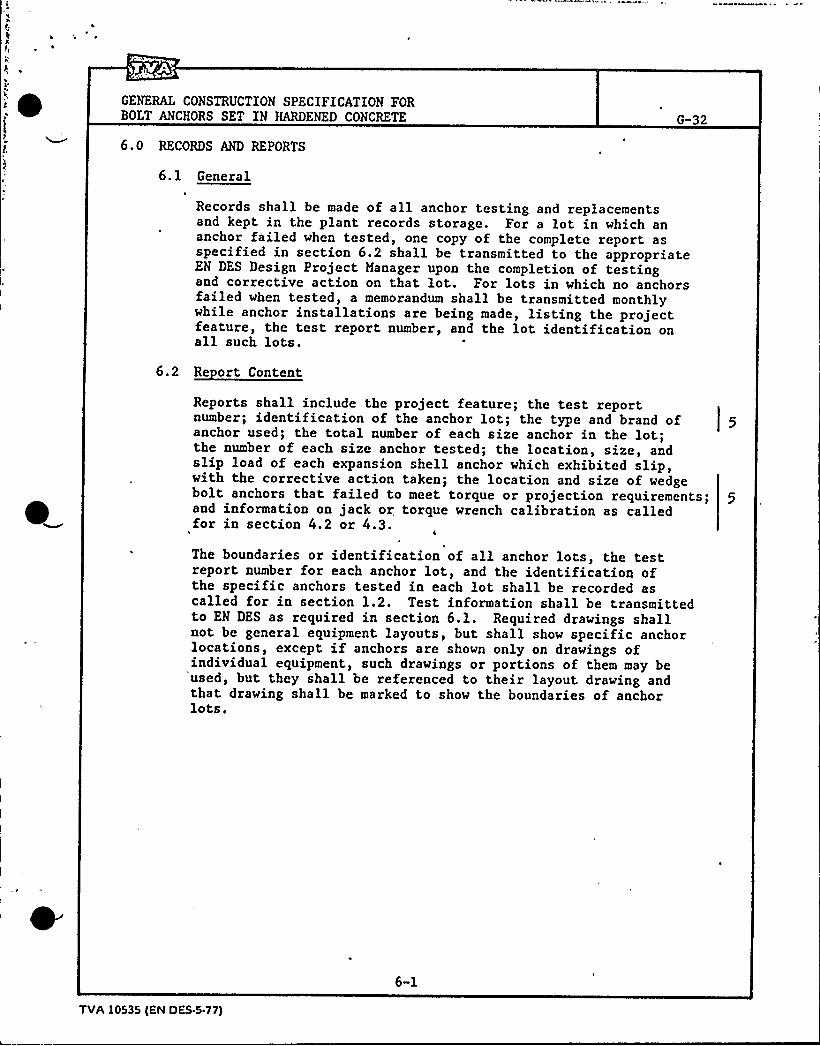
~ ~
GENERAL CONSTRUCTION SPECIFICATION FORBOLT ANCHORS SET IN HARDENED CONCRETE
6.0 RECORDS AND REPORTS
6.1 General
G-32
Records shall be made of all anchor testing and replacementsand kept in the plant records storage. For a lot in which ananchor failed when tested, one copy of the complete report asspecified in section 6.2 shall be transmitted to the appropriateEN DES Design Project Manager upon the completion of testingand corrective action on that lot. For lots in which no anchorsfailed when tested, a memorandum shall be transmitted monthlywhile anchor installations are being made, listing the projectfeature, the test report number, and the lot identification onall such
lots'eports
shall include the project feature; the test reportnumber; identification of the anchor lot; the type and brand ofanchor used; the total number of each size anchor in the lot;the number of each size anchor tested; the location, size, andslip load of each expansion shell anchor which exhibited slip,with the corrective action taken; the location and size of wedgebolt anchors that failed to meet torque or projection requirements; 5and information on jack or torque wrench calibration as calledfor in section 4.2 or 4.3.
The boundaries or identification of all anchor lots, the testreport number for each anchor lot, and the identification ofthe specific anchors tested in each lot shall be recorded ascalled for in section 1.2. Test information shall be transmittedto EN DES as required in section 6.1. Required drawings shallnot be general equipment layouts, but shall show specific anchorlocations, except if anchors are shown only on drawings ofindividual equipment, such drawings or portions of them may be
'used, but they shall be referenced to their layout drawing andthat drawing shall be marked to show the boundaries of anchorlots.
6-1
TVA 10535 (EN DES.5-77)

GENERAL CONSTRUCTION SPECIFICATION FORBOLT ANCHORS SET IN HARDENED N
AppendixA
QUALIFICATION TESTS FOR EXPANSION SHELL ANCHORS
A.l SCOPE
This method of test shall be used to determine the ultimate tensilecapacity of expansion shell anchors (type SSD and SPD). Testsshall be made on each brand, type, and size of anchor that is tobe used.
A.2 APPARATUS
The apparatus shall consist of that required by section 4.2.1.
A.3 PROCEDURE
Place a minimum 8-inch-thick concrete slab with 3/4»inch-maximum sizeaggregate in accordance with 6-2. The average compressive strengthof two field-cured standard cylinders shall be between 3000 and 4000psi at the time of anchor testing.
Install three anchors of each size in accordance with section 3.2.The minimum edge distance shall be 6 nominal bolt diameters and theminimum anchor spacing shall be 12 nominal bolt diameters. The drillbit diameters shall be those required by section 2.3. Thread thehigh-strength rod into the anchor. Center the jack and bearingdevice over the high-strength rod and adjust the location until therod is axially concentric with the center hole of the jack. Placethe bearing plate on top of the jack and snug it down against theram of the jack with the nut. Load the anchor uniformly and withoutshock until the anchor fails.
A.4 REPORT
The report shall include the anchor brand, type, and size, the ultimatetensile capacity of each anchor, the average ultimate tensile capacityof each 3-anchor set, the mode of failure of each anchor, and theconcrete class and compressive strength at the time of anchor testing.
A-l
TVA 10535 (EN DES.5-77)

GENERAL CONSTRUCTION SPECIFICATION FORBOLT ANCHORS SET I
AppendixB
QUALIFICATION TESTS FOR WEDGE BOLT ANCHORS
B.l SCOPE
This method of test shall be used to determine the ultimate tensilecapacity of wedge bolt anchors (type WB), to determine if theinstallation torque given in section 3.3 will result in the requiredpreload, and to determine the required installation torque if thetorque given in section 3.3 does not result in the required preload.Tests shall be made on each branch, type, and size of anchor that, isto be used.
B.2 APPARATUS
1. Calibrated center-hole hydraulic jack equipped with a gage whoseleast division represents no more than a 100-pound load.
2. High-strength coupling nut, a high-strength threaded rod (rodsize and yield strength shall result in a yielding force in therod at least 20 percent greater than the required ultimate tensilecapacity of the anchor), and a bearing plate and nut for attachmentto the jack.
3. Bearing device for transferring the jack reaction to the concretesurface at least 15 inches from the anchor centerline and whichis adjustable to ensure that the anchor is loaded axially.
4. Calibrated torque wrench.
B.3 PROCEDURE
Place a minimum 15-inch-thick concrete slab with 3/4-inch-maximumsize aggregate in accordance with G-2. The average compressivestrength of two field«cured standard cylinders shall be between 3000and 4000 psi at the time of anchor testing.
Install three regular length wedge bolt anchors of each size inaccordance with section 3.3. The minimum edge distance shall be 10nominal bolt diameters and the minimum anchor spacing shall be12 nominal bolt diameters. The drill bit diameters shall be thoserequired by section 2.3 for qualification tests. Install eachanchor through a steel plate or plates which have a total thicknessequal to the maximum attachment thickness given in section 3.3.The bearing plates shall be small enough to permit the bearingdevice to bear on the concrete. Before tightening and withoutchanging the bolt projection, remove the plate and install a thinner


GENERAL CONSTRUCTION SPECIFICATION FORB C
B.3 PROCEDURE (Continued)
plate, or if multiple plates were used, remove one or more of theplates, so that sufficient threads are available for tightening andcoupling to the loading device. Tighten the anchor to the torquegiven in section 3.3.
Couple the high-strength rod to the anchor. Center the jack andbearing device over the high"strength rod and adjust the locationuntil the rod is axially concentric with the center hole of the jack.Place the bearing plate on top of the jack and snug it down againstthe ram of the jack with the nut.
Load the anchor uniformly and without shock until the washer can bemoved with the fingers (lift-off). If the load at lift-offis greaterthan 1.5 times the working load tension of section 3.7, the installationtorques given in section 3.3 are acceptable. If the lift-offloadis less than 1.5 times the working load, loosen the nut and thenretighten to a torque approximately 10 to 20 percent greater thanpreviously used. Reload to lift-off. Continue lift-offtests untila torque which produces the required tension is achieved. The averagetorque for the three anchors of each size tested shall be theinstallation torque.
After completion of lift-offtests, load the anchor until the anchorfails.
B.4 REPORT
The report shall include the anchor brand and size, all data relatingto determination of installation torques, the ultimate tensile capacityfor each anchor, the average ultimate tensile capacity of each 3-anchor set, the mode of failure of each anchor, and the concreteclass and compressive strength at the time of anchor testing.
B»2

ATTACHMENT B

AFD HEADraalLLaprAaaoaaaarr
Mf-IIIIllilngan&OIS~ Drillsitsown hole, eliminating
costly carbide bits.~ Resists shock and vibration.
~ installs fast, easily and economicallyI/Iith the 747 Roto Stop Hammer.
aa
~or.r >y -A-ja
The REDHEAD Self-DrillingAnchor provides its own case-hardenedsteel drillfor every hole, eliminating the need for expensive and easilydamaged carbide drills. Its unique design assures consistent holdingcapacity plus superior resistance to shock and vibration. It's the most
dependable heavy duty anchor in the industry. Installation with the747 Roto Stop Hammer creates one of the fastest, simplest and most
economical "anchoring systems" in the world.
INSTALLATION
PHYLL)PSRed Head'
~ a
: ~
n
aln»
'1. faRILL HOLE- Remove anchorand clean out hole. Place
eed plug In anchor.
E. EXPAND AMCMOR-Ralnxadanchor ln hola and expandunIII flush. Snap off cone.
3. BOLT-Secure obJect tocomplete Installation.
(o
o)
0
h'4ad POA
42b
4„ad ~~4'r
do a 4o A,er,a~.
C'
gal@
a
d dru + d5XS <~ 4
I I 'I I gadu 4 42O+ag 4~d2
dg
l/
I ~
x
Snap oft~ type
For Instailationwith electricor aif Ifnpact
, hammers.
Cat.No.
~ S14~ 516~ 5.38~ S-12~ 5-58~ 5-34~ 5-78
BoltSlee
j}
]Ixrv
yr
OepthIn Con-crete
Igr]pir]lgr
31]( r
threadOepth
y»/+a ~
](E"s]( r9'"
]k"] $]n r
Outs deOlam-eter
Jf »
']fr"]fr)](ryear]r
]I/r
Pullout
3670406056708500
11,70016,200]7550
Shear
1335203033706720
]1.90016,200]8,450
'Load Capacity In3500 Pdh.l. Concrete,
LBS.
PHJ L LIPSRed Head'
~
Flushtype
For hand Instal-lation with
FH-300 seriesflush/hofdera.
{See P.16)
Cat.Ne.
~ f 4~ f.16~ F48~ F12~ F58~ F.34
BoltSizey»]frjgryrI"7p r
Oeplb]bread In Con.Oepth crete
per]14»
I/I
Wr4'',]rhx r2 /)
xa
3»
Outs dcBlam.sterJf »
rg'pa r']('1
'oad Copse ty In3500 PS.I. Concrete,
]BS.
Pullout
3670406056708500
11,70016.200
Shear
1335203033706720
1],90016,200
'avsoe orh lruserohndrnt Tvatlhg Lsborhrory testa. Report hvallabr ~ on P. 21.Tests coroeucted In atone Eggrvgdte concrete.
FOr mvnuIEClulerh reeOmrhoduled ~ EIV Eaarhlrhg lOada uSE 2SV Ot EbOW IOEd Valuea.sl ~ EI ~ or ~ Ecvvds v.s. oouarnprvrhr o.sA spvcllhcalion No. FF<42$ ~ orguro III,Typo 1. IOEIEe el so/sTI
For lhEIEREIIoh ldh ~ Iruclurvl Ilghl EEEIght copocrvl ~ v EE rooc or the vborv toad rEIMEE.
a ~,
pa
rQ~r ~
rignear '

4

D OB 2 R N E Bc EL GE N S ON, Consulting EnginccrsIISRE WEDDINOTON STR EET NORTH HOLLYWOOD. CALIFORNIA ~ TRIANGLE 7iSOSI
File No. 626
September 25, 1962
Xhillips Drill Com pany.Michigan City, Indiana
REPORT
PULLOUT CAPACITIES OF PHILLIPS RED HEAD CONCRETE ANCHORS ASAFFECTED BY SPACING
In compliance with the request of the client, Doberne 4 Elgenson conducted aseries of tests to develop the information used in this report. 'Ihe testfacilities of the Smith-Emery Company, an independent testing laboratory,were used,
The purpose of these tests was to determine the load holding characteristicsof Phillips anchors under various spacing arrangements.
IResults
1, When the spacing between adjacent anchors reaches a distance equal toseveral times the anchor diameter, there is no loss in capacity. Thefollowing table shows the minimum center-to-center spacing thatcould be used with each anchor without causing a loss in individualcapacity,
Anchor Bolt SizeMinimum Spacingfor 100% capacity
1/4" 5/16N
3 II 3 1/4ll 4 II 5ll
3/8ll 1 /2tl 5/8 II
6 II
3/4" 7(8ll
81l
2. When the center-to-center spacing, as shown in the above table isreduced, the capacity of the individual anchor decreases.
The following table shows center-to-center spacing corresponding toa 20% reduction in individual anchor capacity.
Anchor Bolt Size 1/4" 5/16" 3/8" 1/2 II /8ll 3/4 ll 7(8"Minimum Spacing 1-1/2"for 80% Capacity
1-5/8" 2tl 2-1/2" 3 ll 3 1/2 II 4 II
I
I
I
'
F330P
I
Dimensions of blocks used for tests were 8" x 8N x 16N with an averagecompressive strength of 2650 psi.
Res pectfully submitted,4 bkNor ris Doberne, C. E., S. E.

ATTACHMENT C,


PNILVI~ANDNOAO
IXX Phillips DrillCompanyMichigan City, indiana 46360
SPACING, EDGE AND END DlSTANCE RECOMMEMDATlONS*
SELF-DRILLtNG ANDNON-DRILLINGANCHORS
Anchor Size, Inches
Spacing Distance, Inches
Edge And End Distances, InchesLoad Parallel Or Away From Edge
Load Toward Edge 3Va
3V4
2s/4
3 /4 5Va 5Vi
STUD, WEDGE AND SLEEVE
Anchor Size, Inches
Spacing Distance, Inches 1a/4 2Vz 2't/a s/a
4s/a 5V4
SV4
Edge And End Distances, InchesLoad Parallel Or Away From Edge
Load Toward Edge
'I Va 1s/4
2 2s/a
2t/a
274 3Vz
3'/a 4t/a
4Vz 5Vz 6V4
MULTI-SET
Anchor Size, Inches
Spacing Distance, Inches
Edge And End Distances, InchesLoad Parallel Or Away From Edge
Load Toward Edge
2a/a
274
SV4
5%
'Distances for 100% of "Safe Working Load". To determine the "Safe Workfng Load" consult general catalog.
Q
fs.rs) Form «r$ 2lr


TENNESSEE VALLE,Y AUTHORITYDIVISION 5F ENC)NRERING OESIGN
f70
~Y
ALL PROJECTS
GENERAL
COI'v STR UCTION SPECIFICATIONNO. G-32
FOR
80LT ANCHORS SET IN HARDENED CONCRETE
: r~-r ~~"rp ) f ~T > PQ!SepI'eeber 1972 U jQ ~Q J','QPPT
SPONSOR ENGINEER
SUBMI TTED
. E. SullocZ
0. H. Reine
SPECIFICATIONS SECTIO~. L. Duncan
APPROVED
R EVIEWED + ~e.kLC. H. Glaze
RECOMHENDEDF- P.
/«4g'P "
APPROVED
of Construction
Di ctor of Engineering Design
CI
C ~ ~ ~


GENERAL CONSTRUCTION SPECIFICATION
NO G-32
FOR
BOLT ANCHORS SET IN HARDENED CONCRETE
SectionCOSTSS1S
GENERAL
1.1 Scope1.2 Drawings1.3 The Engineer1.4 Reference Specifications1.5 Definitions
2. KKTERIALS
2.1 Expansion Anchors2.2 Grouted Anchors2 3 Bolts2.4 Portland Cement Grout2.5 Epoxy Grout
3. XtSTALLATION
3.1 Expansion Anchors3.2 Grouted Anchors3.3 Location3.4 Embedments
4. res4.1 Selection4.2 Equipment4.3 Procedure
5 ~ REPIACEK2iT
5.1 General5.2 Removing Slipped Anchors
6 ~ RECORDS AND REPORTS
6.1 General6.2 Report Content

GEHKQL CONSTRUCTION SPECIFICATION
NO. G-32
BOLT ANCHORS SET IN HARDENED CONCRETE
1.2
1.3
IGfffEEAL
gcope. Zt is the purpose of this specif'ication to prescribe materialsand methods for setting threaded, anchoring devices for equipment andfixtures into concrete which has previously hardened. The workincludes installation procedures and testing of selected anchors.
Testing is required on expansion anchors f'r all equipment in nuclearplant Category X structures.
Draufn s. Anchors for all Category I equipment fn nuclear plant,structures shall be provided according to drawing prep"ared by theDivision of'ngineering Design. Anchors f'r other equipment shallbe provided according to drawings prepared by the Division oi D
' or if so directed according to manufacturer,'sp
Desi n.recuirements as approved by the Division of Engineering es gn.Changes sha11 be made only wraith the approval of the Engineer.
The projec o Ance st f hall prepare drawings showing the location oftestiand test infonmtion on each lot of'nchors which require es ng.
The En ineer. The Engineer as used in this specification shall mean
t tion. For design considerations, these shall be thee r riate Desi nDivision of'ngineering 3)esign acting through the approp g
Branch Chief. For construction, in general, these sha23. be jointthe appropr a e esxgni t D n Branch Chief and the project ConstructionEngineer. Any e a~aAny d vi 'on from this specification must be agreed to
oin - by hem.
3.,4 Reference S ecifications. The latest revisions of the fol1cnringspecifications shsi1 apply where referred to in this specification.
American Socie y for Testing and Materials:A 36 - Standard Specification for Structural SteelA 307 - Low-Carbon Steel Externally and Internally Threaded
Standard FastenersC 144 - Standard Specification for Aggregate for Masonry MortarD 63S - Standard Method of Testing for Tensile Properties of Plastics

Corps of Engineers, U.S. Army:CRD-C590 - Federal Specification Grout, Adhesive, Epoxy Resin,
Flexible, Filled.
Tennessee .Va13.ey Authority:General Construction Specification No. G-2 for Plain and Reinforced
Concrete
le5 Definitions. Wherever the ~ords defined below appear in thisspecificationp they shall have the meanings here given.
Anchor. d threaded device for'ttaching equipment and fix'tunes toexisting hardened concrete. An expansion anchor expands iatersldX aportion of its length against the sides of a drilled hole to transferload. A grouted anchor is a headed bolt, or threaded rod, with anend. nut, in a drilled hole the remainder of which is. filled withgrout to transfer load..
Lot. This applies o~ to nuclear giant Category l structures. Alot of anchors shall consist of (a) the anchors for a single piece
of'quipmenthaving three or more anchors, or (b) all the anchors on aMoor, wall, or ceiling surface which has convenient ind1catedboundaries, or (c) a long line of anchors on a floor, wall, orceiling for a continuous structure such as a cable tray. Anchorsinstalled in separate construction operations shall be considered,to be in separate lots.
Slim. During testing an anchor sha11 be considered to have exhibitedslip if the gage on the loading device indicates a dropoff or lackor advancement of load while the anchor is being strained.
1-2

E ansion Anchors. Unless otherwise called. for on the drawings,expansion anchors shaLl be used on1y with bolts smaller than 1-inchdiameter. 'or al1 equipment in nuclear plant Category I structures,and for other eouipment unless otherwise called for on the drawings~such anchors shaU. be Phillips Red Head, Self-DriU.ing Anchors,Phillips DrillConpany, Incorporated, Michigan City, Indiana~ orequal.
2.2 Grouted. Anchors. Unless o herwise called for on the drawings, grouted'nchors shall be used for all anchors requiring bolts 3.-inch diameteror larger, and. where replacement of slipped. expansion anchors withother expansion anchors is impractical.
2-3
2.4
Bolts. Unless otherwise called for on the drawings, all bolts sma13.erthan 1-inch diameter shall conform to ASTM A 307, Grade A, and allbolts of 1-inch diameter or larger shall be made of rods which conformto ASTH A 36, with nuts conforming to ASTN A 307, Grade A. Rods shallhave coarse threads on both ends with anut on the embeMed encl whichis tack welded in place.
Portland Cement Grout. All material shaill conform to the requirementsof General Construction Specification Ho. G-2. Cement may be Type I,or Type II. The ratio by weight of water to cement shall not exceed.0.5. A gelling agent or pu~ing aid~ or a grouting aid. incorporatinga gelling agent shall be used in sufficient quantity to preventbleeding. Sand conforming to AS' 144, except that no more than10 percen shall pass the le. 100 sieve, shall be added in as greata quantity as willprovide adequate flowability. Anchors using suchgrout r~ be placed, in service in 7 days provided that the exposedsurface has been protected from drying and that temperatures of theconcrete have been maintained above 50 F.
2.5 h:.. 6 '
component ra io one to one by volume. One component shall be 100percen reactive resin with an epoxide equivalent of 175 to 195.The o her component shall contain polyethylene amines together withnecessary diluting agents and fillers. The mixed material shallhave a minimum nonvolatile content of 98 percent, an initial viscosityof 1800 to 2200 centipoise at 75 F, a minimum pot life of 25 minutesat 75 F~ and. the ability to cure at temperature down to 35 F. After7 days cure at 75 F, tne tensile strength by ASTM D 638 shall be aminimum of 5500 psi, and the compressive shear streng h by CRD-C590,except that the 2-inch cubes used in the test shall be steelshall be a minimum of 2000 psi. The manufacturer shall certifythat the material supplied meets the requirements and shall furnishccraplete ins ructions for its use. Such instructions shall befollowed in de'ail. Sandblast sand or other oven-dry fine aggregate
2-1
with none passing the No. 100 sieve shall be aMed. 9n as great a quantityas willprovide ad,equate f1owability and, wetting of the sides of thehole. Anchors may be placed in service when fina3. cure is achieved..Accelerated. curing according to manufacturer's instructions ispermis'sible.
2~2
3. INSTALLATION
ZEI—""manufacturer's instructions. Special care shall be taken to cleandust and. debris from holes before expanding the anchors.
3.2 Grouted. Anchors. Holes shaLL be drilled ten nomina3. bo3t diametersin depth and. with a cLiameter twice the nomina1 bo3.t diameter. Ho1esshall be cax efully cleaned, of a33. dust and. cLebris. Grout comp3yingwith either section 2.4 or section 2.5 may be used. unless otherwiseindicated on the drawings.
Mhere grout willnot flow from the hole, the ho3.e sha13. be fi33.edapproximately ha3.f fu11 of grout and the bolt inserted. by twistingand working in and out to ensure elimination of all voicLs. Anyremaining hole shall then be fi11ed with grout, the bolt shall befixed in position and the grout cured..
Mhere grout will f3.ow from the hol, the hole and. anchor shall. befitted with a cover plate of wood. or other materia1 through whichthe grout can be pressure injected. A snuQ3. pipe vent sha13. 'beplaced to th highest elevation in the ho3.e and. grout injectedthrough a port in the cover plate until it flows from the vent.Both the port and the vent shall then be pos5.tive3y closecL off.The cove'r plate shall be coated with a bond, preventing material onthe grout side and sha13. be xemoved after the grout has cuxed.
3.3 ication. Unless otherwise indicated on drawings~ no anchor shal3.be 3.ocated. closer than five bolt diameters to a free concrete edgeor ten bolt diameters to an adjacent bolt.
3.4 Enhedments. Required. embedments of all anchors shaLL be fxom thef'ace of structural concrete and shall not include topping or cladding.Mhere self'-driU.ing anchors axe used, topping or cladding shall bepredrillecL to admit the drill chuck to the proper depth.
3-1

4.1
4.2
Testing is required on expansion anchors for all equipment in nuclearplant Category I structures. Tests sha13. be made s.s soon afterinstallation of a lot as is practicable.
Selection. Anchors to be tested. shs13. be random'elected, withina lot after installation of'he lot. If.there are anchors of morethan one bolt size in a lot,"the size difference shall be ignoredunless some anchors are twice the size of the smallest anchors. Inthis case, approximately one-third, of the tests sha31 be on thesmaller size(s) and two-thirds shall be on the larger size(s).
If a lot contains less than five anchors, test at least one anchor.If' lot contains five to fifteen anchors, test at least two anchors.If a lot contains sixteen to sixty anchors, test at least threeanchors and if a lot contains more than sixty anchors~ test at least5 percent.
E»»uEXment,. A callbratea center-hole hrdraultc $ach e»tutppea trlth agage whose least division represents no more than a 100-pound, load.on the anchor shal3. be used to load 'the anchors. The load, shall betransferred. from the pack to the anchor with a high-strength threadedrod with a minimum yield, strength of 50,000 psi. The reaction fromthe pack shall be delivered to the concrete surface through a devicewhich bears no closer than 8 inches radially from the anchor center-line and which is adjustable o ensure that the anchor is loaded.axi~.The calibration of the pack shall be checked every 2 months orevery one hundred, anchor tests, whichever occurs first. If anyquestion as to the pack's accuracy occurs, the pack shall berecalibratede
4.3 Procedure. The high-strength threaded. rod shall be inserted in theanchor or coupled to the bolt of the anchor. The hydraulic packand bearing device shall be centered over the threaded rod anda(/usted until the threaded rod is axially concentric with thecenter hole of the Jack. A nut and bearing plate shall be puton the threaded rod and snugged against the ram of the pack.Zoad shall be applied without shock and as uniform3y as practicableto the proof load as follows:
Bolt size (in. ) 1/4 5/16 3/8 3./2 5/8 3/4 7/8
Proof load (lb) 900 1700 2200 4000 5400 7600 8300
If an anchor slips, it shall be reset and retested or it shall bereplaced and. the new anchor tested (see section 5). If an anchorslips in being retestcd, it shall be replaced. If an anchor slips,an ad)acent anchor shall also be tested. (The proof loads listedare approximately either Oe9 of the minimum yield loads of the bolts,

or are 0.5 of the pu33.out capacity of the concrete surrounCing theanchor, based. on concrete strength of'000 psi but used. a1so withother strengths. Any failure which occurs at the proof losci orbelow should. be by slow frictional slippage of the anchor withinthe hole.)
4-2

5 REPIACEHENT\
5.1 General. An anchor which requires xeplacement shal3. be replaced by1 i expansion anchor or hy a arocteK anchor of'he
same or larger bolt size as the anchor replaced.. A grouted. replace--ment anchor will not require testing.
5e2 Remov1 S3.i ed Anchors. Anchoxs which slip under test loadingsha11 be xemoved by the test equipment except that the hydraulicpack shall bear directly against the concrete around the anchor,or by an a1ternate method which prevents spelling of the concretesurface.
5-1

~ ~
1
6 RECORDS KG) REPORTS
6.1 General. Records shall be kept of all anchox teWing and replacements..f rte eheht he trenemttteg to the Ctv|1 Design Breechas 'the testing in each lot is completed~ or once monthly if installationand. testing of several sxQacent lots is continuing.
6.2 Re ort Content. Reports shall include the boundaries of each anchorh total number of each size anchor in the lot, the number
of each size anchor tested,, and. the location of each anchor whicchexhibited slip with the corrective action tegmen.
All the information shall be recorded on the project office drawingscalled for in section 1.2, snd. prints of the drawings transmitted asrequired in section 6.1. Xf successive reports cover anchors on thesane drawings, tests and, test results since the previous transmittalsha13. be iden~ified. Tne drawings sha13. fin~ include aU. test results.

ATTACHMENT D
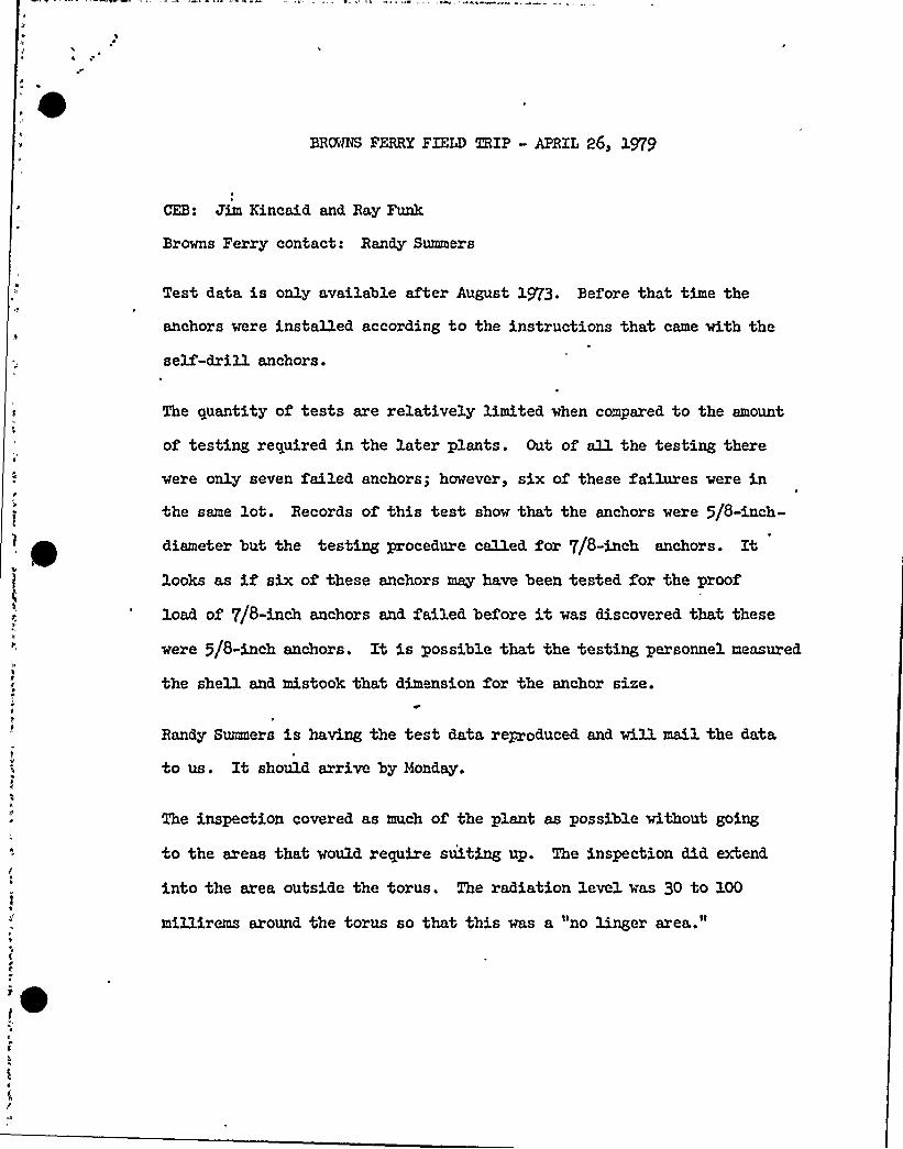
BRANS FERRY FIELD TRIP - APRIL 26, 1979
CEB: Jim Kincaid and Ray Funk
Browns Ferry contact: Randy Summers
Test data is only available after August 1973. Before that time the
anchors were installed according to the instructions that came with the
self-drill anchors.
The quantity of tests are relatively limited when compared to the amount
of testing required in the later plants. Out of aU. the testing there
were only seven failed anchors; however, six of these failures were in
the same lot. Records of this test show that the anchors were 5/8-inch-
diameter but the testing procedure called for 7/8-inch anchors. Itlooks as if six of these anchors may have been tested for the proof
load of 7/8-inch anchors and. failed before it was discovered that these
were 5/8-inch anchors. It is possible that the testing personnel measured.
the sheU. and, mistook that dim nsion for the anchor size.
Randy Summers is having the test data reproduced and wiH. mail the data
to us. It should arrive by Monday.
The inspection covered as much of the plant as possible without going
to the areas that would require suiting up. The inspection did extend
into the area outside the torus. The radiation level was 30 to 100
mil3.irems around the torus so that this was a "no linger area."

The general type of use of self-drills were not the type that is of ma)or.
concern in the NRC 79-02 bulletin. l was not able to find any instance where
multiple rows of anchors were loaded through flexible plates. The use of
tube section cantilever system welded to unstiffened plates was noticable by
their absence.
Xn three instances anchorage failures were observed. Xn each case it was
obvious that the support system was not operating the way it was designed.
These were very stiff support systems for which the direction or magnitude
of load producing failure was not anticipated. in design. The best way to
check anchorages is by inspection of the gap and. protrusion of the anchor
shell. The best time to catch this is inspection during hot testing or on
outages by people who know what the anchors should be doing.
When some of these pipes lock up and move in an unexpected direction they
can overpower almost any anchor. When these are found it needs attention to
get the systems to where they are compatible whether it means readgusting
the strap, relocating the support, or changing the anchorage.
l

It would not be a desirable axea for testing since it would require that the
work crews would have to work near the ceiling where the radioactivity was
at a maximum. This might cause the crew to get the maximum dose in the
short time they would be in there.
In general the support systems tended to be the type of'lexible loading
that is best suited f'r self-dry. anchors. Cable trays were supported from
a channel that was anchored. to the ceiling. Trapeze rod hangers then were
connected to the channel f'r tray support. When lateral support was required,
wide flange sections were attached to the wall and ceiling in an L shape.
Large piping appeared to generally be supported on embedded plates which
had been installed for that purpose. It was always the smaller piping systems
that were located after the concrete had been poured, that required the use
of post installed anchors. The ma)ority of these systems were primarily
tension type devices that work best with the self-drill anchors. Typical
installations were single xod. hangers going to a single anchor for lightloads and a plate with four anchors where heavier loading was required.
These plate systems would tend to have the load limited by the xod. capacity
instead of'he anchor capaci4y. These would not be a ~or problem to test
since the xod. and. plate could be removed. to test the anchors.
Prior to G-32, there was no difference in installation and. testing between
class 1 end non-category systems so that testing of non-safety xelated systems
could be expected. to represent the general level of workmanship that was
used at the time without Jeopardizing a safety system.


g ~
r gg
~ e ~ I
r I
R / ~
t
R5
QI. l
r %g
R
/ ~ l

/ ~
~ /
/ ~
~ ~

H
g ~
R
8gll
I
/
lit% R
/ /II:
ISSUE

A')-I ] 8/Ith ~ .. <h
(t~p '..! .!Ql.) .
I
I
.. jo/./
..I/d~
:.. lp./d. efp
a'C !j, o/oI i //
p/.ddIen
II7!
~ ~
ljI I
jlta
a
I~
I<I R~;I ddt~ I
7co6dh~Z
~ ~
'aQ
~ C'.
~ I
.. "dgtons
.. II'IIII,'d.d
I
'. N/d.'I
.dS,.data
do
I'P
IIsa
&jj'h
J!I
/P.
Overt
dd
jj
I't
I e
I s
I'.
il]Ijl'IjlI ~
~ I
I
I /f77,,
4'I. 1
~ ! II.S
is /$ /tg~i I
ili 43
nsi /$79.
~ I
+(Io//
d/vl
JJ(
potdo
dZD//
~ I ~
I I~ ~
aI;I I
I ~ ]/~tri,It)gj
~. jav
,. sN4: . Sh.hl
I
. '. IddI
s
~ ~
I pd1
t I~ a
:IIII
j
jT
II'
'
.nC
jI
c'p7
I:t-III
a
d/a
Is II ~ .
~ Is
~ ~
n/i.'i
~ IiI II I~ ~
S
'a
I~ ~a
I I-a
Tr
~ ~
I ~
s~ ~
IS
tlnn
I ~
I
I ~
I~ ~
~ ~
C
!I
IelI
RJ e eaw~~w>J'~ ~ ~ ~ ~
~eae ee~
S~ ~ ea> r~ aa n ~ ~ '~ ~ e'a ~ arses a ~ aaaa e aa ~
Peal; ~((ri ''m S':: rm-:~ =/m":y ..:."'. 'iAYi .'.~',.!. -'
.R'n -3 Plier-g.
!I;t.
;I
!
I'I
ajI
a
~ I
Olj
~ ~
e I
I
I
I
AarAAe~ ii
)Ij'I I
IIII!
!I
I)T "I
lis ~
I II I
I
I
I
jI,IlIj:I
!
I I
~ r
l'j
a
~/.ale4/Hajji
.,:ac~i ..
.,I„,II
I;hntI
jaj
ij',. le.r
7;i:rI!~ ~
'„I
sfI.a.I.
'I~ ~aa
I~
~
is', Ij'
ta;I
I
ijI
a
II ~
e~ I
a rA...4yr .I
~ ~
1 ~.~:.:
. ~pl. Is a
''t..; o( jl'.
d
'/S ~i
.. i/t'.
...oct.~.r >.
~ I ~
sl
,, 11
r s
ISa
'I--.I
':mt .u
jI::!:'T:
~ ~
II ~
I-'
~s a
~ e
alI:~ ~
~ ~
!I
IiI','
.IIsa
li
I ')
~ 'a
s
s~ I
j.
f
E
~ ~
I
ll
. Is
tl~ I n
~ sfe ti
~ ~ ~ ~
Inn
$ÃQ w~ 0 ~ ~ ~ ar
IS ~ I
„TTa aa
~ ~'l~~~
'~ ~
~ ~a
~ a
I a r~ ~ -L
'a ~
I s
I tI
I s
I e
I ~~ ~
e
I Ial
Il.
)j~ ~
~ II a
~ ~
aa
~ ts
1
e II ta ~
~ ~
's'
a t ~ I
jI
I
~ I
I ~
, I
I)
'I s
IIa
~ t
liI II '.
1;j:jl~ ~ ~
t.aaI t
II!a.I
a
~ ~ I~ t~ ~
e 'a
s
I's'
r'
I ~ti t~ ~
~ ~ ~
~ ~
II I
'~ 4
lit~ ~
~ ~ I
I
N
liIlll
s
sl ~
I a"j -lI
-I
S ~ e,e ~ a ~ ~ t~r ~ tta ~ ttetr esa ~ ovtr ttt etta tSt ~ate%+ ~ ~

ENCLOSURE 2
TENNESSEE VALLEYAUTHORITY
DIRFCT RADIATION LEVELS AROUND BROWNS FERRY
NUCLEAR PLANT - BACKGROUND DATA
This Report Contains Preliminary InformationSubject to Change or Revision and IsIntended for Use Within TVAOnly
- WNV48ION OF ENVIRONMENTALPLANNING
DIRECT RADIATION LEVELS AROUND BROWNS FERRY
NUCLEAR PLANT - BACKGROUND DATA
By
PHILLIP H. JENKINS AND RICHARD L. DOTY
TENNESSEE VALLEY AUTHORITY
MUSCLE SHOALS, ALABAMA
FEBRUARY 197,7
OVERVIEW
In 1974, a study was conducted by various agencies of the federal govern-ment to develop a research program dealing with the human health and
environmental effects of energy use. This program was developed by.,utilizing lists of health and environmental problems associated witheach of eight energy-generating technologies. Research 'objectives and
prospects responsive to the research needs of each technology then were
developed.
One of the technologies studied was energy generation by nuclear power.
Radiation exposure desigri objectives applicable to the nuclear power
industry are established at levels believed to be as low as reasonablyachievable consistent with current technology and societal objectives.Approval for the construction and operation of nuclear power',plants isdependent on the assurance of safe operation in compliance with these
design objectives. Because this assurance is demonstrated by analyticalmethods, the validity of the models and the accuracy of the assumptions
is of utmost importance for the timely and economical development ofnuclear power..
Current dose models are based on assumptions which are believed byutility and regulatory personnel to be conservative; however, revision
. of these dose models may not be )ustified without supporting data.Although limited, short-term studies have been conducted around operating
~
'uclear~~ts to facilitate comparisons of actual and predicted„values, these -"pri objects have not provided the necessary data for compre-
hensive verific4e9'on of the methodology of analytical do'simetry; Therefore,research ~ds were identified within the nuclear technology regarding

verification or revision of dose models. High priority was given to thecollection~+information and the development of programs pertinent tothose needs, e~s'pecially those needs regarding the environmental transportof radionuclides.
1
'VA
proposed a program of evaluation of dose models used for the assess-
ment of the radiological impact from an operating nuclear power plant.This program included collection of experimental data around a power
plant and the evaluation and revision of existing atmospheric dispersionand dosimetry models.
TVA was noted to be uniquely qualified to develop improved analyticalmodeling capabilities, because of its extensive involvement with nuclearpower plant operations and expertise in radiological monitoring and
modeling technology. The required information-providing organizationswould all- be available within TVA, which would reduce the potential forcommunications problems in an arrangement'f plant operator and outsidecontractor. Further, implementation of the p'roposed program into TVA'8
existing assessment operations could be accomplished at minimal costcompared to establishment of a separate assessment program, because ofthe availability of support facilities, equipment, and personnel.Therefore, in response to the proposal, TVA was funded to initiatestudies related to the validation of dose models. Work is beingperformed under the administration of TVA's Radiological Hygiene Branch
in the Division of Environmental Planning. This document is the firstreport to be issued by the staff as a result of the funding.
r ." ~,i. ~ ~

CONTENTS
~Pa e
Overview
List of Tables
Acknowledgments Ui
Sections
IntroductionHa teria ls and He thod s
Experimental Phase
Discussion,Summary and Conclusions
References
14
35
37

TABLES
No. ~Pa e
1 Summary of Data — Direct Radiation Levels — Browns
Ferry Nuclear Plant
2 Comparisons Between Data Collected During the Day and
During the Night17
3 Comparison Among Zones
4 . Locations Grouped by Exposure Rate
5 Comparison Among Instruments of Mean Fxposure Rates
6 Comparison Between Integral and Rate Methods—Simultaneous Measurements
20
21
'23
26
7 Comparison of Integral and Rate Measurements By
'Instrument.28
8 Results of Analyses on Background Data Taken .Accordingto the Plume Detection Design
33

ACKNOWLEDGEMENTS
This report is submitted in partial fulfillment of interagency agreement
EPA-IAG-D6-E721, subagreement number 5, with funding under the administra-tion of the 'Fnvironmental Protection Agency (EPA). The authors wish tothank James A. Oppold, Frnest A. Belvin, and Eric W. Bretthauer for theirefforts in the management of this project. Appreciation is also extended
to William W. Wilkie, Walter S. Liggett, J. Herschel Davis,. James L. Pierce,Richard D. Smith, Brenda J. Williams, and Sadie B. Holmon.


INTRODUCTION
This report presents the results of initial measurements of directradiation levels around a nuclear power plant. 'hese data and data
collected at later times will be used in revising computer codes used
in calculating doses to individuals located near nuclear power plantsites. Both a computer code which estimates doses resulting from
exposure by submersion in the gaseous effluent plume from the plantand a code which estimates doses to individuals off-site resulting
'rom exposure to radioactive materials confined within the plant are
expected to be revised. Additional data and the revised codes will be
the sub)ect of future reports. Revision of these codes will lead to
improved assessment of the impact of nuclear facilityoperation.'ata
collected through June 1976 are presented in this report. The
purpose for this data collection was threefold: (1) to obtain dat'a inthe vicinity of a nuclear power plant which was not operating. These
data could be, considered to be background, control, or nonoperational
data; (2) To evaluate the performanc'e of instruments to be used in the
collection of additional data; and (3) To evaluate methods which might
I
I
Ir't
I
be used to identify or quantify doses received from radiation exposure'romradioactive materials in the effluent plume. Reviewers should be
aware that major effort to date has been focused on developing and
evaluating a framework for future study. This report is not a finalreport-'„-'en model refinement or facility assessment, but rather a repo
~Q~~~.on accompli'sl>m'ents in the first year of a five-year study.
~r'
Three boiling water reactors make up the power-generating capacity ofTVA's Browns~gerry Nuclear Plant (BFNP). Each of the units is capable
of producing l,152 megwatts (lN) of electricity, making the complex
one of the largest nuclear power facilities in the world and an excel-lent statio'n" on which to base studies of the impact of nuclear facilityoperation. A temporary shutdown of the facility, beginning in 1975,
provided the opportunity to gather a unique set, of data; that is, data
at a large facility where construction activities had been essentiallycompleted but where all reactor units were nonoperational. The data
discussed in this report were obtained at BFNP during this period offacility shutdown, utilizing pressurized ionization chambers.
4
MATERIALS AND METHODS
Five instruments capable of accurately measuring environmental levels of
gamma radiation were purchased for 'this project. These instruments are
the Reuter-Stokes Environmental Radiation Monitors, Model RSS-111, Serial
Nos. T-3512, T-3513, T-3514, T-3516, and T-3517. A sixth instrument,
Serial No. T-3590, was loaned to the project from within the Radiological
Hygiene Branch for brief periods of use.
The RSS-ill utilizes a high-pressure ionization chamber for the detection
of gamma rays. The chamber is a 25.4-cm (10-in.) sphere of 3.05-mm
(0.120-in.) stainless steel containing pure argon at a pressure of
2.5 x 10 Pa (25 atm). Mien .gamma rays interact in the chamber, an elec-
trical current, is produced. This current is measured by an electrometer
and is directly related to the gamma-ray exposure rate.
The instrument has a digital display consisting of light emitting diodes
(LED's) from which the instantaneous exposure rate can be read directly'n units of microroentgen per hour (yR/h) over 'the operating range of 1
to 500 3IR/h. The exposure rate is also recorded at intervals of approxi-
mately two seconds on a strip-chart recorder. The. instrument contains
an exposure integrator which measures the total exposure accumulated ~ I
over a period of time. „The read-out device for the integrator isa six-digit mechanical register which is incremented 6nce for every micro-
~ roentgen of accumulated exposure. The instrument can be operated using,'t'ormal
~~gbjjig current (AC) power or a rechargable battery pack which
„ can be used for',-up to-200 hours of continuous operation.P
tm='' - ~
.a
~~
Agg!A%av
MATERIALS AND METHODS
Five instruments capable of accurately measuring environmental levels of
gamma radiation were purchased for this project. These instruments are
the Reuter-Stokes Environmental Radiation Monitors, Model RSS-ill, SerialNos. T-3512, T-3513, T-3514, T-3516, and T-3517. A sixth instrument,
Serial No. T-3590, was loaned to the project from within the Radiological
Hygiene Branch for brief periods of use.
The RSS-ill utilizes a high-pressure ionization chamber for the detection
of gamma rays. The chamber is a 25.4-cm (10-in.) sphere of 3.05-mm
(0.120-in.) stainless steel containing pure argon at a pressure of2.5 x 10 Pa (25 atm). %%en gamma rays, interact in the chamber, an elec-
trical. current is produced. This current is measured by an electrometer
and is directly related to the gamma-ray exposure rate.
The instrument has a digital display consisting of light emitting diodes
(LED's) from which the instantaneous exposure rate can be read directlyin units of microroentgen per hour (pR/h) over the operating range of 1
to 500 llR/h. The exposure rate is also recorded at intervals of approxi- ',
I
mately two seconds on a strip-chart recorder. The instrument contains
an exposure.integrator which measures the total exposure accumulated
over a period of time. The read-out device for the integrator isa six-digit mechanical register which is incremented once for every micro-
roentgen of accumulated exposure. The instrument can be operated us'ing* ~ ', M'-:-,
normal'N+mgtejgg current (AC) power or a rechargable battery pack which
can be used for,'.up to 200 hours of continuous operation. ~" ~~g
'W'* c
A .p, ~'

Fach instrument was calibrated by the manufacturer before shipment. The
calibratioq~pof the instruments has been checked by project personnel~r<it <~
using a Ra-226'source. However, a rigorous recalibration procedure, has
not yet been established.
When an environmental radiation measurement is made, the sensor head,
which contains the ionization chamber and the electrometer, is placed
.on a tripod such that the center of the chamber is approximately one
meter (3.3 feet) above the ground. The control circuitry, read-out
devices, and battery pack are in a separate control housing, which iselectrically connected to the sensor head by a six-meter, (20-foot)
cable and is placed at least three meters (10 feet) from the sensor
head. The details of the operating procedure for the instrument are
contained in the manufacturer's instruction manual.
Because various read-out devices are included in. the instrument, several
methods of determining the exposure rate are possible. Two methods have
been used in this project. The first method is referred to as the "rate"
method, because the exposure rate is read directly from the LED display.The exposure rate value observed on the display fluctuates rapidly due
to the random nature of radioactive decay. Therefore, several exposure
rate readings must be averaged to obtain a meaningful measurement using
this method.. Furthermore, this must be done in a consistent manner inorder to make valid comparisons among measurements. The procedure thatwas established for this project consists of manually recording the
value from the LFD display at approximately six-second intervals untilfifty values have been recorded. The mean of the fifty readings is then
considered to be representative of the exposure rate over the approxi-
mately five-minute duration of the measurement.
The rate method has two main advantages. First, a short period. ofsl
time is~~for each reading; therefore, one can take measurements
at several locations during a workday. Second, the variation of the*
" exp'osure ra0eMMn also be measured. As part of this method, the~~~3t „
4
C

I J

Each instrument was calibrated by the manufacturer before shipment. The
calibrationgyf the instruments has been checked by project personnel
using a Ra-226~iource. However, a rigorous recalibration procedure, has
not yet been eptablished.
When an environmental radiation measurement is made, the sensor head,
which contains the ionization chamber and the electrometer, is placed
qn a tripod such that the center of the chamber is approximately one
meter (3.3 feet) above the ground. The control circuitry, read-out
devices, and battery pack are in a separate control housing, which iselectrically connected to the sensor head by a six-meter (20-foot)
cable and is placed at least three meters (10 feet) from the sensor
head. The details of the operating procedure for the instrument are
contained in the manufacturer's instruction manual.
ACCtDbss ~.
Because various read-out devices are included in the instrument, several
methods of determining the exposure rate are possible. Two methods have
been used in this project. The first method is referred to as the "rate"method, because the exposure rate is read directly from the LED .display.
The exposure rate value observed on the display fluctuates rapidly due
to the random nature of radioactive decay. Therefore, .several exposure
rate readings must be averaged to obtain a meaningful measurement using
this, method. Furthermore, this must be done in a consistent manner inorder to make valid comparisons among measurements. The procedure thatwas established for this project consists of manually recording the
value from the LED display at approximately six-second intervals untilfifty values have been recorded. The mean of the fifty readings is then
considered to be representative of the exposure rate over the approxi-
mately five-minute duration of the measurement.
f»~
II
The rate method has two main advantages. First, a short period of ~
~Jtime is~gg~o~ each reading; therefore, one can take measurements
at several 'locations during a workday. Second, the variation of the '
4+~
exposure rate„:eaii also be measured. As part of this method, theI I
r'.
>Pi

standard deviation of the fifty readings is routinely calculated and
recorded.+gAlso, the fifty individual readings are available if a
detailed analysis of the distribution of these data is desired;
The rate, method also has two main disadvantages. First, someone must
be present during the measurement to perform the somewhat tedious taskof recording the fifty individual exposure rate values. Second, if a
fluctuating source of radiation is present in the environment, a five-minute measurement may not be sufficient to quantify or even to detectthe contribution due to that source.
The second method used to measure exposure rate utilizes the integratorand is referred to as the "integral" method. Using this method, theaccumulated exposure is read from the mechanical register, and thetime over which the accumulation occurred is measured with a stopwatchor other timing device. Since the mechanical register displays onlyinteger values of exposure in microroentgens, care must be taken thatthe elapsed time measured with the timer corresponds to an integralnumber of microroentgen'ncrements. The following procedure is used..
The instrument is allowed to warm up for approximately two minutes,after which the timer is started as closely as possible to the instantthat the mechanical register is next incremented. Generally, when
only background radiation is present, the timer is started when the
regi.ster is Xncremented'rom 0 to 1 pR. The initial reading isrecorded, and the instrument is allowed to-accumulate additional micro-roentgens. At the end of the'measuremen't, the timer is stopped as
closely as possible to 'the instant that the last microroentgen incre-ment is, recorded on the mechanical register. The final registerreading and the elapsed time are recorded. The overall exposure
rate during the measurement is calculated by subtracting the initial.readinI+rom the final reading, and dividing
The integral'ood has two main advantages.
is longer w1t'Xi~he integral method than with
by the elapsed time.
First, the measurement time
the rate method; therefore,
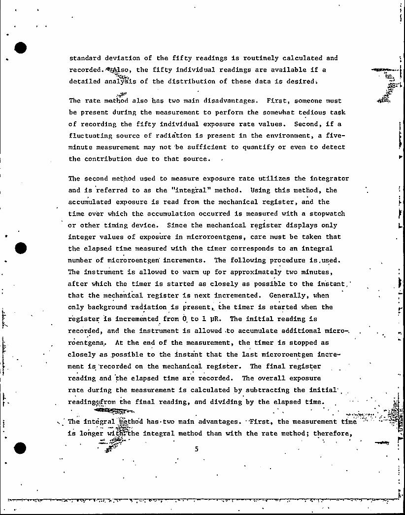
standard deviation of the fifty readings is routinely calculated and
recorded. <also, the fifty individual readings are available if a~fdetailed analysis of the distribution of these data is desired;
The rate method also has two main disadvantages. First, someone must
be present during the measurement to perform the somewhat tedious taskof recording the fifty individual exposure rate values. Second, if a
fluctuating source of radiation is present in the environment, a five-minute measurement may not be sufficient to quantify or even to detectthe contribution due to that source.
The second method used to measure exposure rate utilizes the integratorand is referred to as the "integral" method. Using this method, the
accumulated exposure 'is read from the mechanical register, and the
time over which the accumulation occurred is measured with a stopwatch
or other timing device. Since the mechanical register displays onlyinteger values of exposure in microroentgens, care must be taken thatthe elapsed time measured with the timer corresponds to an integralnumber of microroentgen'ncrements. The following procedure is.used.The instrument is allowed to warm up for approximately two minutes,after which the timer is started as closely as possible to the instantthat the mechanical register is next incremented. Generally, when
only background radiation is present, the timer is started when the
register is incremented from 0 to l pR. The initial reading isrecorded, and the instrument is allowed to accumulate additional micro-.
roentgens. At the end of the measurement, the timer is stopped as
closely as, possible to the instant that the last microroentgen incre-ment is 'recorded on the mechanical register. The final registerreading and the elapsed time are recorded. The overall exposure
rate during the measurement is calculated by subtracting the initial"reading+>.', rom the final reading, and dividing by the elapsed time.
~IS~~.The integral method has two main advantages. 'irst, the measurement time
is longer witP,',the integral method than with the rate method; therefore,'f
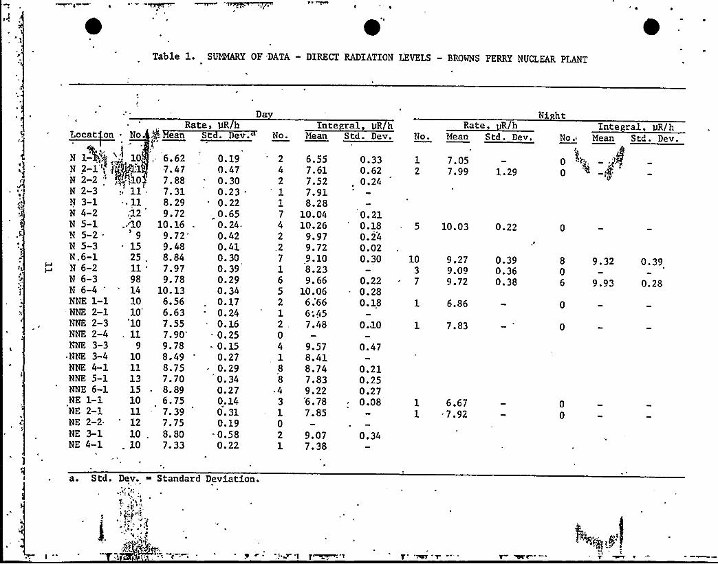
Table 1. SUMMARY OF DATA - DIRECT RADIATION LEVELS - BROWNS FERRY NUCLEAR PLANT
Rate,Locat on No ;$ ean St
.'N 1%,'$.',: 10 .. 6.622-1 (t 3 g'1 7 ~ 47
N 2-2 ' '10 7.88N 2-3 ll; 7.31N 3-1 ~ 11 8.29N 4-2 ;12 9.72N 5-1 ..10 10.16N52. 9 972N 5-3 . 15 9.48N „6-1 25, 8. 84N 6-2 11 '.97N 6-3 98 9.78N 6-4 '4 10. 13NNE 1-1 10 6.56NNE 2-1 10 6.63NNE 2-3 10 7.55NNE 2-4 . 11
7.90'E
3-3 9 9.78ANNE 3-4 10 8.49NNE 4-1 ll 8.75NNE 5-1 13 7.70NNE 6-1 15 ~ 8.89NE 1-1 10 6.75NE 2-1 11 - 7.39NE 2-2 12 7.75NE 3-1 10 . 8.80NE 4-1 . 10 7.33
pR hev.
0.190.470.300.23 .
0.220.650. 24-0.420.410.300. 390.290.340.170.240.160.250.150.270.290. 340. 270. 140. 310. 190.580.22
Da
No.
2 6.554 7.612 7.52
' 7.911 8.287 10.044 10.262 9.972 9.727 9.101 8.236 9.665 10.06212,.04188
~ 43102
6;666;457.48
9.578.418.747.839.22'6. 787.85
9.077.38
0.330.62
„ 0.24
0.210.180.240.020.30
0.220.280.18
0.10
0.47
0.210.250.270.08
0.34
Inte ral gR hMean Std. Dev.
Rate R/hNo. Mean Std. Dev.
1 7.052 7.99 1.29
5 10. 03 0. 22
10 9.27 0. 393 9.0Q 0.367 9.72 0.38
1 6.86
1 7.83
1 6.671 - 7.92
Ni htInte ral, gR/k
No.- Mean Std. Dev.
p :.'g, „ (14p
0
8 9.32 0.3906 9.93 0.28
0
0
00
a 0 Std. Dev. ~ Standard Deviation.A
i»
g~ ", g$
pl l~3
~ g< ~ ~ ~T
~ g

Table 1 (continued) 'UMMARY OF DATA — DIRECT RADIATION LEVELS — BROWS FERRY NUCLEAR PLANT
4.
NE 4 2~-jp.gy10< f-.9. 14NE 5-1 ( ~fPj.'0." 9.27NE 6-1 '"10' 7.84ENE 1-1 , 9 '.77ENE 2-2 9. 6.60ENE 2-3 - 10 '.24ENE 3-.2 '10 8.54ENE 4-1 14 '9.51ElE 5-1 13 '.40ENE 5-2 9 9.96ENE 6-2 .11 8'28E 2-1 '0. 7.12E 2 2 . 11 . 8 20E 3-1 10 ~ 6.86E 3-2, 10, 8.39E 4-1,, 'l7 7.41E 5-1 15 '10. 19ESE 1-1 10 '7.88ESE 2-1 11 ':76ESE 3-1 11 7.58ESE 4-1 13 9.85
. SE 1-1 16 9.60SE 2-1 10 7.32SE 3-1 'l 9.57SSE 1»1 16 8.59SSE 2-1 '2 6.14S 1-1 '6 10.14S 1-2 . 16 7.84 .
te uR/h
0. 170. 340. 110. 260. 150. 180. 260. 210. 360. 320.530. 170.200.250.230. 300.230. 350. 330. 290. 170. 900. 370. 190. 340. 21.0. 861.19
Std. Dev. Ro.
1
31
42
1
2851
1
321
2991
01
7
2361
21
2
Mean
9. 31-9. 138.006.877.118.258.749.629.69 .
9.929.137.148.426 . 8,1
8. 377.48
10.257. 86
7.619.889.477.029.518.686.27
11.018.90
ral /hStd. Dev.
0.62
0.330.98
0.260.130.41
0.270.08
0.420;280.20
0.211.750.040.14
'.23
0.08
No.
Ni htRate R/h
Mean S td . Dev.
1 6.781 6.80
5 7.29
4 7.13
0.13
0. 11
1 8.219 6.849 - 7.709 10.051 10.169 7.568 9.921 8.548 6.221 11.09
0.230.440.25
0. 350.29
0. 12
Inte ral UR/hNo. Mean Std. Dev.
j(
00
0
0
000008 7.711 9.6201 6 . 1'2
0
0. 26
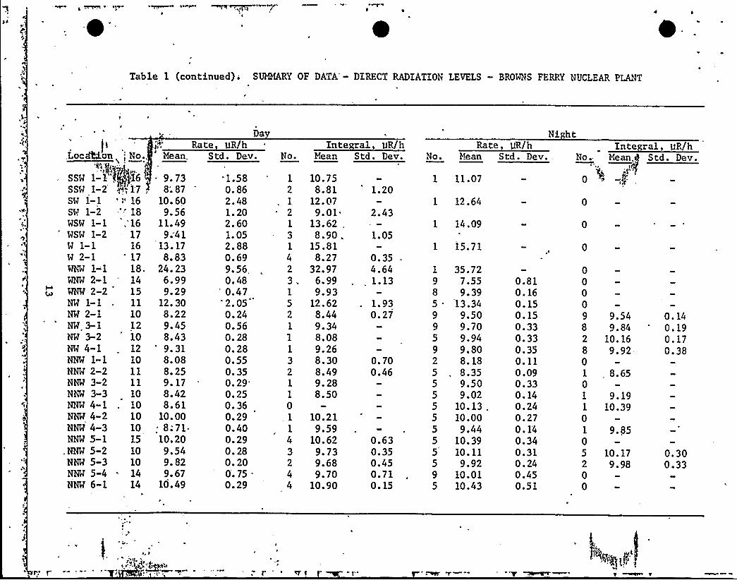
Table 1 (continued) ~ SUMMARY OF DATA - DIRECT RADIATION LEVELS — BROWNS FERRY NUCLEAR PLANT
W 2-1hhw 1-1WNW 2-1
'718.14
WNW 2-2 15NW 1-1NW 2-'1NW 3-1NW 3-2NW 4-1NNW 1-1NNW 2-2NNW 3-2NNW 3-3NNW 4-1NNW 4-2NNW 4-3NNW 5-1
.NNW 5«2NNW 5-3NNW 5-4NNW 6-1
ll1012101210llll101010101510101414
,Loc~on No.,'IA) y"-"))8
SSW l-l'f 16SSW 1-2 y<"„''7,SW l-l 'tSW 1-2 '; 18WSW l-l, 16WSW 1-2 17W 1-1 16
n$'t
~
Mean.
- 9.738;87
10. 609. 56
11. 499;41
13. 178.83
24. 236.999. 29
12. 308.229. 458. 43'.318. 088. 259. 178.428.61
10. 00. 8;71-10. 209.549. 829. 67
10. 49
Rate, gR/hDa
1.580. 862. 481. 202. 60l. 052. 880.699. 56,0.48'.472. 050. 240. 560. 280. 280.550. 350.
29'.
250. 360. 290. 400. 290. 280. 200. 750.29
Std. Dev. No.
1
2
1
21
31
23.1
521
1
321
1
0
32
4
10.758.81
12.079.01
13.62 „
8.90 .15. 818.27
32.976.999. 93
12.628.449.348.089.268.308.499.288.50
10.219.59
10.629. 739.689.70
10.90
1.20
2.43
1.05
0. 354.641.13
l. 930.27
0.700.46
0.630.350.450.710. 15
Inte ral, UR/hMean Std. Dev. No.
985.
.99592
555555
5595
Ni htRate gR/h
Mean Std. Dev.
11.07
12.64
14.09
15.71
35.727.559. 39
13.349.509.709.949.808.188.359.509.02
10. 1310. 009.44
10.3910.119.92
10.0110.43
0.810. 160. 150. 150.330.330.350.110.090.330. 140.240.270. 1'4
0.340.310. 240.450.51
Inte ral, gR/hNo. Yiean,g Std. Dev.
0 0 g:
0
0
0
00009
82801
01
1
01
05200
9.549.84
10.169.92-
0. 14
0. 190. 170.38
, 8.65
9.1910.39
9. 85
10. 179.98
0. 300.33

z.

DISCUSSION
TEMPORAL VARIATION
The background exposure rate at a given location varies slightly withtime, mainly due to fluctuations in meteorological conditions. These
variations, are usually gradual,'taking place .over a period of severalhours. flowever, precipitation can cause an abrupt increase in thebackground due to the washout of radon decay products. For this reason,data collection during periods of precipitation was avoided'.
The standard deviations presented in Table 1 for the daytime data
provided an estimate of the day-to-day variation in the exp'osure rate at\
each location. At most locations this variation was small. From thedata collected by the rate method, the standard deviations at 71 of the83 locations were less than or equal to 0.75 pR/h. At these 71 locations,the ranges of the rate measurements were less than 1 pR/h at 44 locations,between 1 and 2 pR/h at 24 locations, and greater than 2 pR/h at onlythree locations. The largest range, 2.38 pR/h, was observed at NNW 5-4.
At the remaining twelve locations, the standard deviations varied from0.86 to 9.56 pR/h, and the ranges in the rate measurements varied from2.26 to.27.87 pR'/h. The greatest variat'ion was observed at WNW 1-1,where the rate measurements varied from 8.20 to 36.07 PR/h. This vari-.
Iation is too large to be due to fluctuations in the background alope.1.ocation:WNW 1-1 is in very close proximity to the area of the plantwhere;low=reve.Vradioactive waste is packaged and stored until't is 'd
.~
shipped.'ll+g .the'twelve locations except SE 1-'1'are close to the.plant and on+he same side of the plant as the radwaste area. The
~~14 ~ .

0

measured exposure rates at these locations have been observed to decrease
after a segment of radwaste has left the plant. It has been concluded4:+!
that the radwaste contributed to the exposure rates measured at thelocations in~he S, SSW, SW, WSW, and W sectors, plus WNW l-l and NW 1-1.
~r'r'ecausethe exposure rates measured at these locations contained a
contribution due to the plant, these rates were excluded from comparisons
with background exposure routes at other locations.
The standard deviation value of 0.75 1JR/h seemed to be a reasonable,'utsomewhat arbitrary, cutoff between the locations that were unaffected bydirect radiation from the plant and the locations that were affected.Location W 2-1 was included in the latter group, even though the standard
deviation of the rate measurements made there was less than 0.75 pR/h.
This inclusion was made because fluctuations, in the exposure rate at thatlocation seemed to be correlated with fluctuations in the measurements
, made at the other locations that were included. Location SE 1-1 was notincluded in this group because it was well shielded from the radwaste
area, and because the fluctuations in exposure rate at that location did
not correlate with the fluctuations at the other locations. However,
another source of radioactivity within the plant may have affected the
exposure rate at SE 1-1.
~eggggmmewv
'if'he
variation in the data collected hy the integral method at each
location was similar to the variation in the data collected by the ratemethod. As mentioned above, there were 71 locations where the standard
deviations of the rate measurements were less than or equal to 0.75 pR/h.
Two or more integral measurements were made at 43 of these locations./
At two .of these locations, the standard deviations of the integral measure-
ments were greater than 0.75 pR/h; 0.98 pR/h at FNE 2-2 and 1.13 pR/h atWNW 2-1. 'hese standard deviations were based on only two measurements .
at ENE&-.2 and three measurements at WNW 2-1. At the 43 locations, the
ranges o tVe&ntegral measurements were less than 1 WR/h at 33 locations,- v +me,m 'l„l wv
between 1 an~;.pR/h at seven locations, and greater than 2. pR/h at onlyone locatio~The largest range, 2.20 WR/h, was observed at WWW 2-1.
I.iC
~ ~
15
~ Te

Two or more integral measurements were made at seven of the twelve
locations agre the standard deviations of the rate measurements were
greater than'OC'75 lJR/h. At six of these locations, the standard devia-
tions of the integral measurements were greater than 0.75 )JR/h. The one
exception was at S 1-2 where the standard deviation was 0.08 pR/h. This
standard deviation was based on only two measurements. The ranges ofthe inte'gral measurements at the seven locations varied from O.ll pR/h
at S 1-2 to 6.56 pR/h at MNW 1-1.
The nighttime data, a summary of which is included in Table 1, were
limited in quantity, but were sufficient to provide comparisons between
daytime and nighttime measurements at a few locations. A one-way analysisof variance (ANOVA) was performed on both the rate and integral data foreach location where at least two measurements were made, both during the ~
day and at night. In Table '2, the actual number of daytime and night-time measurements that were involved in each comparison is indicated.For each comparison, the difference is presented as the average of thenighttime measurements minus the average of the daytime measurements.
Comparisons were made for 29 locations using the rate measurements. For
twelve. of these locations, the differences between the daytime and night-time, measurements were statistically significant. For all twelve ofthese locations the average exposure rate was larger for the nighttimemeasurements than for, the daytime measurements. The largest differenceobserved; however, was only 1.52 pR/h.
Comparisons using the integral measurements were made for only sixlocations. For two of these locations, the differences between the day-
time and nighttime measurements were statistically significant. In each
case, the average of the nighttime measurements exceeded that of the
daytime measurements. The largest difference observed was 1.10 pR/h.
For thr = ie six locations where comparisons were made using both the'Nrate and integral measurements, the results of the comparisons were not
6
consistent. 'T'other words, the comparison using the rate measurements
16
~ 6q

ll

Table 2., COMPARISONS BETWEEN DATA COL'LECTED DURING THE DAY AND DURING THE NIGHT
Rate Measurements Integral Measurements
Location
N 5-1N 6-1N 6-2N 6-3E 2-1E 3-1ESE 2-1ESE 3-1ESE 4-1SE 2-1SE 3-1SSE 2-1
'NW2-1WNW 2-2NW 2-1NW 3-1NW'-2NW 4-1NNW 2-2NNW 3-2NNW 3-3NNW 4-1NNW 4-2NNW 4»3NNW 5-1NNW 5-2NNW 5-3NNW 5-4NNW 6-1
No-..-~~Da )
.a)v
1025ll981010 .,llll13101112141510121012ll11101010101510101414
No.~(Ni ht
510 .
37
5499998898995955555555
.595
'ifference(Night-Day),
R/h
-0. 130. 431.12
-0.06'.170. 270. 080. 12b0.200.240.350. 08b0.560.101.280.251.510.490.100.330. 601.520.000.730. 190.570.10.0.34
-0. 06
7
32
52
No. No.~(Da ) ~(N5 ht)
D fference~(Night-Day),~l
z40.22
0.27
0.69
1. 10
0.440.30
a. Significant difference at the 0.01b. Significant difference at the '0.05
level.level.
17

showed a significant difference while the comparison using the integralmeasurements did not, or vice versa. These discrepancies probably
4
occurred bee'ause of the small number of integral measurements that were
made. In all three of these cases, however, the differences between
the average4.'of the nighttime measurements and the average of the daytime
measurements were approximately the same for both the rate and the
integral methods.
4
~4f4t
It must be kept in mind that the comparisons between daytime and night-time measurements were based on. a small amount of data. No conclusions
can be drawn concerning the reasons why significant differences were
found for some locations, but not for others. These comparisons do
indicate, however, that significant increases in background'evels
can occur at night. Therefore, if exposure rate measurements are made
at night while the plant is operating, care must be taken to establishthe proper background levels.
SPATIAL VARIATION
The background radiation levels were observed to vary slightly from
location to location. This can be seen from the summary of the data
presented in Table 1. A close examination of the average exposure rates
in Table 1 revealed what appeared to be a spatial trend in the measure-
ments. Specifically, the exposure rates at locations close to the plant'eemedto'e lower than those at locations farther away from the plant.
To determine whether or not such a trend actually existed in the data, a
one-way ANOVA was performed with the six zones as the treatment groups.
The data from all the locations within eath zone were pooled. The data
from the locations in the S, SSW, SW, WSW, and W sectors, and from
locations WNW 1-1 and NW l-l, were not included for the reasons stated
in the previous section. At many locations, the integral measurements
or nightgime measurements were few in number or nonexistent; therefore,
only raWP%i8%urements made during the day were included in this analysis.r,
~ . pt
18
4I ~
tt

The mean and standard deviation for the measurements from each zone, as
well as thgnumber of measurements, are presented in Table 3. The infor-'I
mation in Tabte .3 is arranged so that the mean exposure rates are indescending order. The ANOVA indicated that there was a significantdifference-"-'among the six zones at the 0.01 level. To determine
specifically where the difference or differences were, the mean from
each zone was compared with the means from all the other zones using theScheffe method. The results of these comparisons indicated threedistinct groups, such that there was no significant difference between
the zones within each group, but the mean from each zone in a group was
significantly different at the 0.01 level from the mean from any zone inthe other groups. The .groups were (1) zones 5 and 6, (2) zones 4 and 3,and (3) zones 1 and 2. Therefore, one can conclude that, in general,
'thebackground radiation levels were lower at locations close.to theP
plant than at locations farther away from the plant.
Neasurements from sever'al locations 'did not follow this gener'al trend.Therefore, a better grouping of the locations was sought. A one-way
ANOVA was performed on the same data as'n the analysis above, but witheach locatfon as a treatment group. The ANOUA indicated that there was
'I
, a significant difference among the locations at the 0.01 level. However,
because there were a large number of locations and the means of the
exposure rate measurements formed essentially a continuum'of values from
10.49 to 6.14 WR/h, grouping the locations was very subjective. The
rationale that was used to assign the groups was as follows: (1) no
comparison between two means within a group should show a significantdifference at the 0.05 level using the Scheffe method, and (2) a compari-
son between the largest mean in a group and any mean in the next group ofsmaller means should show a significant difference at the 0.05 level. The
result of this approach was the three groups presented in Table 4. This
arrangement of the locations is very convenient, as the ranges of the
means in ttie'Three„groups are approximately the same. The three groups" '""„-'.""""'~ "were identifiedas "High" (approximately 10.5 to 9 pR/h), "Medium"
19

I ~ ~
Table 3. COMPARISON AMONG ZONES
Zone
r~No. of
-Measurements
142
Mean,gR/h
9.59
Std. Dev., apR/h
0.77
198 9. 39 0.81
129 8. 91 0.95
135 8.60 0.83
91 7.81 1.21
209 7.55 0.82
a. Std. Dev. Standard Deviation.
i ~ 20'

~~
Table 4. LOCATIONS GROUPED BY EXPOSURF. RATE
'Hi h
Location
NNW 6-1NNW 5-1E 5-1N 5-1N 6-4NNW 4-2ENE 5-2FSF. 4-1NNW 5-3NNE 3-3N 6-3N 5-2N 4-2NNW 5-4SF. 1-1SE 3-1NNW 5-2FNE 4-1N 5-3NW 3-1ENE 5-1,NW 4-1
'NW 2-2NE 5-1NNW 3-2 .
NE 4-2
Meyn,pR)h
~Q.O. 4910. 2010. 1910. 1610. 1310. 00
9. 969. 859. 829. 789. 789. 729. 729. 679. 609. 579. 549. 519.489.459. 409. 319. 299. 279. 179;14
'taedium
Location
NNE 6-1N 6-1NE 3-1NNE 4-1NPW 4-3NNW 4-1SSE 1-1ENE 3-2NNE 3-4NW 3-2NNW 3-3E 3-2N 3-1FNE 6-2NNW 2-2ENE 2-3NW 2-1E 2-2NNW l-lN 6-2NNE 2-4F.SF. 1-1
~ N 2-2NE 6-1NE 2-2NNE 5-1ESF. 3-1NNE 2-3
Mean,pR/h
8. 898. 848. 808.758. 718.618.598.548.498.438.428. 398. 298.288.258.248.228.208.087.977.907.887.887.847.757.707.587.55
Location
N 2-1F. 4-1NF. 2-1NE 4-1SF. 2-1N 2-3E 2-1WNW 2-1F. 3-1ENE l-lESE 2-1NE l-lNNE 2-1N l-lENE 2-2NNE l-lSSF, 2-1
Mean,pR/h
7.477.417.397.337.327.317.126.996.866.776.766.756.636.626.606.566.14
21

(approximately 9 to 7.5 pR/h), and "Low" (approximately 7.5 to 6 pR/h).
COMPARISON AMONG INSTRUMENTS
No schedule .w8's used to determine which instrument would be used at a
particular location on a particular day. However, a conscious effortwas made to ensure that at no location was the same instrument used allor most of the time. It was assumed that, especially for any locationwhere a large number of measurements were made, the order in which the
instruments were used was essentially random. Therefore, if there was a
difference in the performance of the instruments, this effect would be
confounded with the day-to-day variation.
Only at location N 6-3 was a sufficient quantity of data collected to
provide a comparison among the instruments. To eliminate other possiblesources of variation, only the data collected during the day using the
rate method were used in this comparison. A summary of these data ispresented in Tab1e 5. Only one measurement was made using the instru-ment that was loaned to the project, No.'-3590; therefore, this instru-ment was not considered in this comparison.
A one-way ANOVA was performed on the data. This analysis showed thatthere was a significant effect at the 0.01 level due to variation among
instruments. The mean exposure rate for each instrument was compared tothe means for the other four instruments using the Scheffe method~ No
significant difference was found between instruments No. T-3512 and No.
T-3514 or between No.'-3517 and No. T-3516. However, the mean forinstrument No. T-3512 was significantly greater at the 0.01 level than
the means for"No. T-3517 and No. T-3516; Also, the mean for instrument
No. T-3514 was significantly greater at the 0.01 level than that for No.
T-3516, and was significantly greater at the 0.05 level than that for No.
T-3517.~The mean for instrument No. T-3513 was not significantly+~~PP~-rdifferent fr'om.any of the other means at the 0.05 level. Because the
mean exposure~te for No. T-3513 was much closer to those for No. T-3512--'y,..., '„'g
and No. T-351'4, it was considered to be grouped with those two instruments
rather than-'No. T-3517 and No. T-3516.
22
~, ~ + ~ ~ I', ~

Table 5. COMPARISON AMONG INSTRUMENTS OF MFAN EXPOSURE RATES
Instrument No.M'o. ofMeasurements
Mean,pR/h
Std. Dev.,pR/h
T-3512
7-3514
T-3513
T-3517
T-3516
26
18
21
14
18
9.95
9.88
9.81
9.58
9. 57
0. 20
0.27
0.27
0.25
0. 22
a. Std. Dev. = Standard Deviation.
23
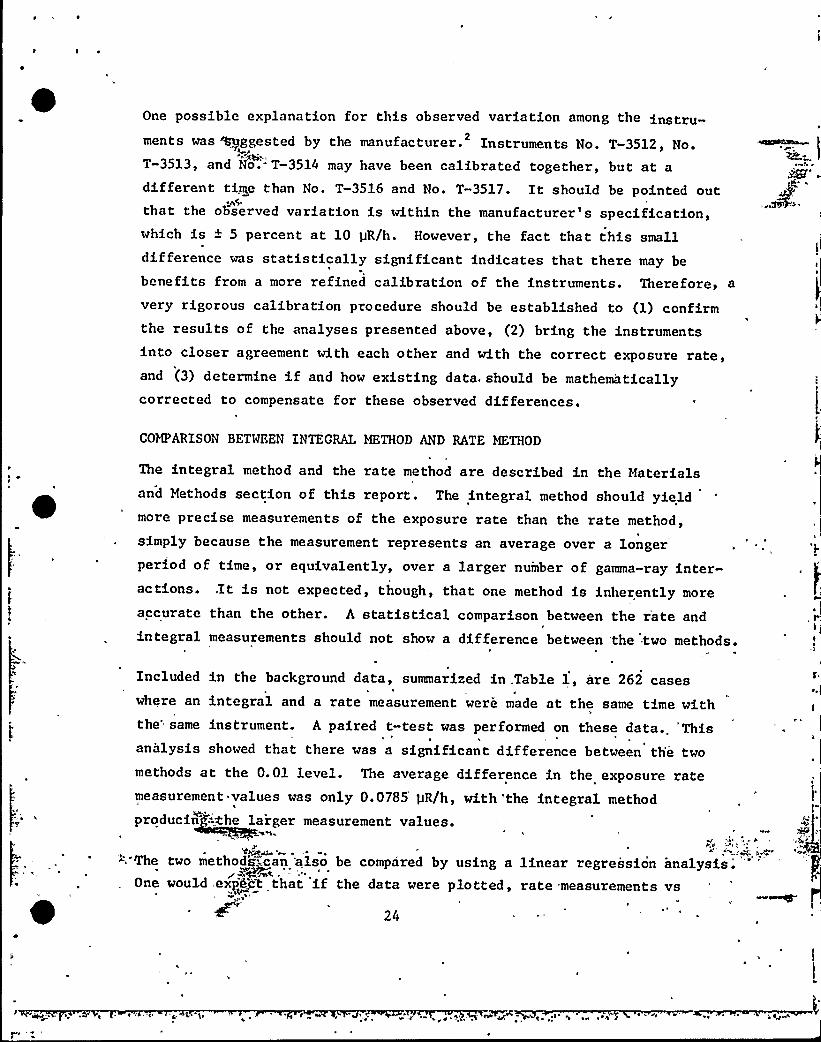
One possible explanation for this observed variation among the instruments was ~ggested by the manufacturer. Instruments No. T-3512, No.
2
'~Hi..T-3513, and No.'- T-3514 may have been calibrated together, but at a
different time than No. T-3516 and No. T-3517. It should be pointed outthat the observed variation is within the manufacturer's specification,which is + 5 percent at 10 pR/h. However, the fact that this smalldifference was statistically significant indicates that there may be
benefits from a more refined calibration of the instruments. Therefore, a
very rigorous calibration procedure should be established to (1) confirmthe results of the analyses presented above, (2) bring the instrumentsinto closer agreement with each other and with the correct exposure rate,and (3) determine if and how existing data, should be mathematicallycorrected to compensate for these observed differences.
COMPARISON BETWEEN INTEGRAL METHOD AND RATE METHOD
The integral method and the rate method are described in the Materialsand Methods section of this report. The integral method should yield
*
more precise measurements of the exposure rate than the rate method,simply because the measurement represents an average over a longerperiod of time, or equivalently, over a larger number of gamma-ray inter-actions. .It is not expected, though, that one method is inherently moreaccurate than the other. A statistical comparison between the r'ate andintegral measurements should not show a difference between the two methods.
Included in the background data, summarized in.Table 1, are 262 caseswhere an integral and a rate measurement were made at the same time withthe'ame instrument. A paired t-test was performed on these data.. 'Thisan~lysis showed that there was a significant difference between the twomethods at the 0.01 level. The average difference in the exposure ratemeasurement values was only 0.0785'R/h, with 'the integral methodproducin -Che larger measurement values.
" The two methods=can 'also be compared by using a linear regression analysis. '"'ne
would,expk~gt that if the data were plotted, rate measurements vs
24
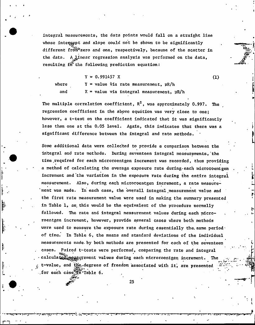
~ I ~
integral measurements, the data points would fall on a straight linewhose inte~pt and slope could not be shown to be significantlydifferent fro~m-:zero and one, respectively, because of the scatter inthe data. A~near regression analysis was performed on the data,resulting M the following prediction equation:
where
and
Y ~ 0.991457 X
Y = value via rate measurement, pR/h
X = value via integral measurement, pR/h
The multiple correlation coefficient, R , was approximately 0.997. The
regression coefficient in the above equation was very close to one;however, a t-test on the coefficient indicated that it was significantlyless than one at the 0.05 level. Again, this indicates that there was a
significant difference between the integral and rate methods.
; ~
Some additional data were collec'ted to provide a comparison between theintegral and rate methods. During seventeen integral measurements,'thetime, required for each microroentgen increment was recorded, thus providinga method of calculating the average exposure rate during each microroentge'n
I
increment and the variation in the exposure rate during the entire integralmeasurement. Also, during each microroentgen increment, a rate measure-
" ment was made. In each case, the overall integral measurement value and
the first rate measurement value were used in making the summary presentedin Table 1, as, this would be the equivalent of the procedure normallyfollowed. The rate and integral measurement values during each micro-roentgen increment, however, provide several cases where both methods
were used to measure the exposure rate during essentially the„ same period.of time. In Table 6, the means and standard deviations of the individualmeasurements made by both methods are presented for each of the seventeen
25
cases. Paired t-tests were performed, comparing the rate and integralr
~ calcula~~~gurement values during each microroentgen increment. The
t-value, and th~.degrees of freedom 'associated with it', are presented, for each .case@'n'Table 6.
)

Table 6. COMPARISON RFTWEHN INTFt.:RAL AND RATE METHODS-
S BmLTANEOUS lKASUREMENTS
Instrument No.
T-3513
T-3513
T-3514
T-3514
T-3514
T-3514
T-3514
T-3517
T-3517
T-3517
T-3517
T-3517
T-35,17
T-3517
T-3590
T-3590
. T-3590
'* In tegra1,PR/h
~ 9.533+.066
9. 396+.066
9. 718+. 103
9.647+.093
9.640+.092
10.043+.080
9.910+.067
10.086+.095
9.852+.093
9.584+.084
9.649+.045
9.922+.119
9. 489+. 098
9.505+.114
10. 036+. 129 "
9.409+..075
9.413+.091
Rate,UR/h
9.554+.106
9.432+.077
9.718+.090
9.608+.101
9.639+.122
9.987+.097
9.860+.085
9.960+.103
9.717+.090
9.450+.101
9.536+.085
9.790+r135
9.349+.122
9.382+.102
9.904+.175
9.308+;076
9. 357+. 144
-1. 339 —Ax
-4.400c
OCOOO
3.053
0.068
4.217c
3 145d
14 47c
12 53c
8.090c
6.107
6.276
10.247
9.400
4.975
6.418
2.696
a ~
b.C ~
d.
Mean + 'one standard deviation.d.f. ~ degrees of freedom.Significant at the 0.01 level.Significant at the 0.05 level.'
26

Two observations can be made from Table 6. First, there= is littledifference~< any, in the standard deviations calculated for the two
methods. For both methods, the standard deviations are approximately
0.1 pR/h. Thu's, it appears that one method is not inherently more precisethan the other for measuring the exposure rate over the same period oftime.'econd, the results of the t-tests indicate that the agreement
or lack of agreement between the two methods may vary from instrument
to instrument.
The 262 cases where, an integral measurement and rate measurement were
taken at the same time were grouped according to instrument, and the
paired t-test and regression analyses, described above, were performed
on the data for each instrument. The results of these analyses aresummarized in Table 7. The paired t-tests indicated, for all the instru-ments except No. T-3513 and No. T-3514, that the integral measurement
values were significantly larger than the rate measurement values atthe 0.01 level. 'The average difference between 'the two methods forthose instruments exhibiting a significant difference, ranged from
0.1093 pR/h to 0.1590 pR/h.
The linear regression analyses showed similar results. The regression.coefficients for all of the instruments except No. T-3513 and No. T-3514
were significantly less than one at the 0.01 level, ranging from
approximately 0.983 to approximately 0.988. This also indicates that,for these four instruments, the integral measurement values were
significantly larger than the rate measurement values.
A potential explanation, which was suggested by the manufacturer, for .2
this observed difference is that the calibration of the integral and /
rate circuitry may vary slightly from instrument to instrument. TheI
observed difference is less than two percent of the exposure rate, and
is well NfEBT5'-the manufacturer's specifications. The fact that these
small differences were "statistically significant, however, indicatesthat there would be benefits if. the instruments were more finely~rcalibrated>~
27

gl

Table 7. COHPARISON OF INTEGRAI. AND RATE HEAS}JREMENTS BY INSTRUN'.N7
Paired t-tests Re ression Anal ses
7.52
T-3513
T-3514
T-3516
T-3517
T-3590
70 0.781
28 -0. 294
43
46
5.30
7.68
4.59
Instrument No. dMa
.sP
T-3512 60
Avg. Difference,R/h
0.1198
0.0127
-0.0090
0.1093
0. 1326
0.1590
Re . Coefficient
0.988046
0.997782
1.000411
0.987826
0.987023
0.983234
R
."99891405
. 9924 3529
.97529875
.98971596
.99854871
.98452253
a. d.f. ~ degrees of freedom.b. Significant difference at the 0.01 level.c. Significantly less than one at the 0.01 level.
28
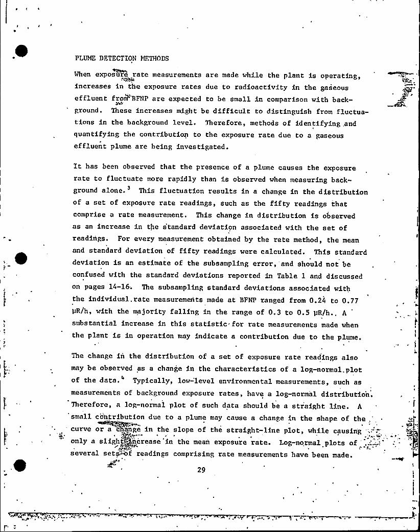
I g ~
PLUME DFTECTION MFTHODS
i%en exposuFe rate measurements are made while the plant is operating,increases in the exposure rates due to radioactivity in the gaseouseffluent from"BFNP are expected to be small in comparison with back-ground. These increases might be difficult to distinguish from fluctua-tions in the background level. Therefore, methods of identifying .and
quantifying the contributioa to the exposure rate due to a gaseouseffluent plume are being investigated.
It has been observed that the presence of a plume causes the exposurerate to fluctuate more rapidly than is observed when measur1ng back-ground alone. This fluctuation results in a change in the distribution3
of a set of exposure rate readings, such as the fifty readings thatcomprise a rate measurement. This change in distribution is observedas an increase in the s'tandard deviation assoc1ated with the set ofreadings. For every measurement obtained by the rate method, the mean
and standard deviation of fifty readings were calculated. This standarddeviation is an estimate of the subsampling error, and should not beconfused with the standard deviations reported in Table l and d1scussedon pages 14-16. The subsampling standard deviations associated w1ththe individual. rate measurements made at BFNP ranged from 0.24 to 0.77pR/h, with the majority falling in the range of 0.3 to 0.5 pR/h.. A
substantial increase in this statistic*for rate measurements made when
the plant is in operation may indicate a contribution due to the plume.
The change in the distribution of a set of exposure rate readings alsomay be observed as a change in, the characteristics of a log-normal. plotof the data." Typically, low-'level environmental measurements, such as
measurements of baclcground exposure rates, have a log-normal distributio'n.Therefore, a log-normal plot of such data should be a straight line. A
'small co'ntribution due to a plume may cause a change in the shape of the,'curve or a 'c ange in the slope of the straight-line plot, while causin'gQ(we ~
only a slight@ncrease'in the mean exposure rate. Log-normal plots of '.-',—.„:.8CP 4
several sets ef readings comprising rate measurements have been made.
29

y ~
These plots have indeed appeared as straight lines. To date, this method
appears toehold promise's a method for detecting the presence of a plume;
however, quantification of plume effects using this method may,not be'>~
possible in,yP.1 cases.
Another method of detecting and quantifying the effect of a gaseous
effluent plume is based on a 3 x 3 Latin-square experimental design.
According to this design, measurements are made at three locations atthe same time. This procedure is repeated three times, once. while thewind is blowing in the direction of each location.
The assumption is made that, except for plume effects, variations inexposure rate with time are the same at each location. In statisticalterms, this is equivalent to assuming that there is no interactionbetween locations and observations. The locations must be chosen care-fully so that this assumption can be made. The locations should be farenough apart that the plume will not affect the exposure rate at more
than'one location at a time. However, the locations should lie withinapproximately a ninety-degree sector with respect to the plant, so thatchanging contributions due to direct radiation from sources within the
plant would affect each location approximately equally. For the same
reason, the locations should be approximately equidistant from the plant.
The ANOVA model for this design is as follows:
RY . 1I + L + 0 + [P(38 — 1)/3]ij (2).
where EYi ~ the expected value of the exposure rate at the
location during the j observation,th th
~ the grand mean,
~ the effect of the i location,th
~ the effect of the 'j observation,. thr
~ the. plume effect,= '1 when i j, and 0 when igj.
- 30
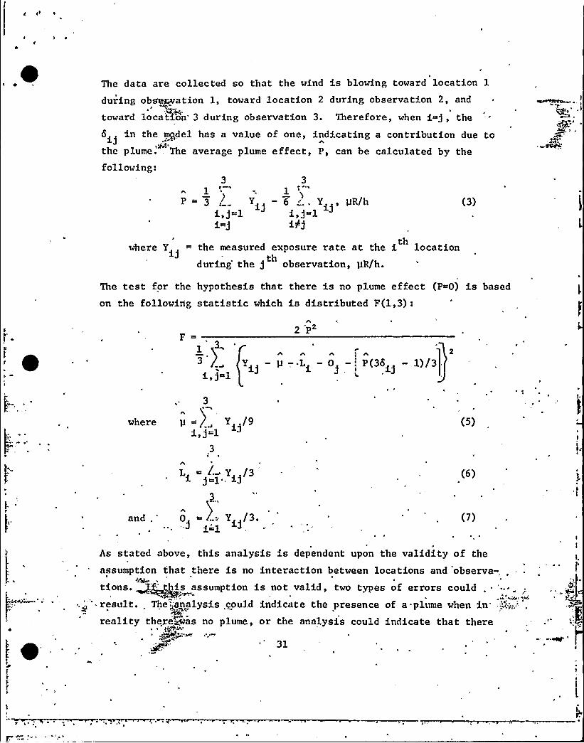
The data are collected so that the wind is blowing toward location 1
during observation 1, toward location 2 during observation 2, and
toward location' during observation 3. Therefore, when i=), thein the mendel has a value of one, indicating a contribution due to
>EXthe plume. The average plume effect, P, can be calculated by thefollowing:
3
)P~3 c
1
3'
6 „'.. Yi, pR/h1i/j
(3)
where Y = the measured exposure rate at the i locationth
during'he g observation, AIR/h.th
The tea t for the hypo thesis tha ton the following statistic which
there is no plume effect (P 0) is based
is distributed F(1,3):
2 P
1,) 1
IA A Ag A 2
Yi) — p —, Li — 0 —l P(36i) — 1)/3
where
and
3
Y /9i, j~l
,3
Li L Y /3
'.,0 ..: Y /3.i 1
J
(5)
(6)
(7)
As stated above, this analysis is dependent upon the validity of the
assumption that there is no interaction between locations and 'observa-, .
tions. ~ ~is assumption is not valid, two types of errors could~ '.," result.. The„:analysis could indicate the presence of a-plume when in
reality ther'eras no plume, or the analysis could indicate that there
J

~ 's a

~ 1+ ~
~ tf
was no plume when in reality a plume was present. To investigate the
validity of the assumption, the analysis was performed on five sets ofbackground P~Fa. Since the plant was not operating, there was no basis
for assigning an assumed plume to a particular measurement. Therefore,
foi each set ck data, there are six distinct arrangements of the data,or ways to assign an assumed plume. These arrangements are notindependent of one another; nevertheless, the analysis was performed
for all six arrangements for-,each of the sets of data.
The results of the analyses are presented in Table 8. The threelocations for each set of data also are indicated. The first threesets of data were taken under the full constraints of the design. The
last two sets were not, however, because the locations were all in the
NW sector and were not equidistant from the plant. Since the plant was
not operating, this should not affect the results of the analyses. The
data in all five sets were based on integral measurements which were
~ approximately one hour long.
' For each of the six arrangements of each set of data, the calculatedplume effect in microroentgens per hour, and the F-statistic associated
with it, are presented„ in Table 8. In all cases the plume effect was
small, less than 0.3 pR/h. In approximately half the cases, the calcu-lated plume effect was negative. A negative plume effect has no physicalmeaning. Also, in all cases, the F-statistic was less than 5.0, which isnot significant. Values of 10.1 and 34.1 for this statistic would be ~
significant at the 0.05 and 0.01 levels, respectively. These .results,indicate that it is not likely that this analysis will show a signifi-cant plume effect when a plume is not,present..
The last two sets of data presented in Table 8 were taken at. the same
locations. Therefore, these data could be analyzed as a replicated 3 x'3 factor4gg. Such an analysis would provide a test on the significanceof the 7nteNKion between locations and observations. Such an analysiswas performed~~.-these data. The F-test for the interaction was notsignificant joe'n at the 0.25 level. Although this test does not provide
32
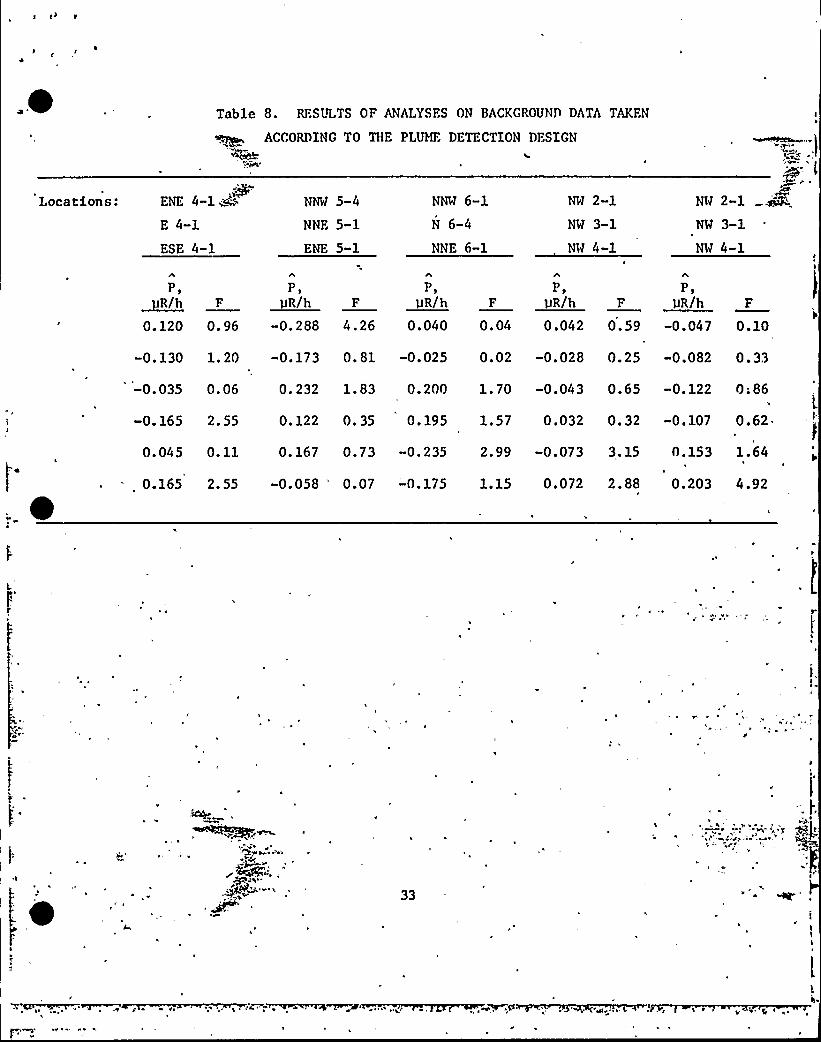
Table 8. RESULTS OF ANALYSFS ON BACKGROUND DATA TAKFN
Locations: ENE 4-1 ~A~'
4-1
ESE 4-1
NNW 5-4
NNF. 5-1
ENE 5-1
NNW 6-1
N 6-4
NNE 6-1
NW 2-1
NW 3-1
NW 4-1
ACCORDING TO THE PLUME DETECTION DFSIGN r
NW 2«1
NW 3-1
NW 4-1
P)~R/h0. 120
F
0. 96
P,IJR/h
-0. 288
F
4.26
P,gR/h
0.040
F
0. 04
P,pR/h
0.042
F
0.59
P,vR/h
-0. 047
F
0.10
-0.130 1.20 -0.173 0.81 -0.025 0.02 -0. 028 0. 25 -0.082 0. 33
-0.035 0.06 0.232 1.83 0.200 1.70 -0.043 0.65 -0.122
-0. 165 2. 55
0. 045 0. 11 0.167 0.73 -0.235 2.99 -0.073 3.15 0.153
0. 122 0. 35 0.195 1.57 0.032 0. 32 -0.107
0;86I.
0.62.
1.64
0.165 2.55 -0.058 "'.07 -0.175 1.15 0.072 2.88 0.203 4.92
33

~ <) a

sufficient evidence to conclude that the interaction will always be
insignificant, the results are encouraging in their support of the
assumption of~o interaction between locations and,observations.I'

~ gI
SENARY AND CONCLUSIONS
The data collected between December 29, 1975, and June 25, 1976,characterized the nonoperational exposure rates at approximately 83
locations in the vicinity of BFNP. It was concluded that direct radia-tion from the plant, specifically from radwaste, affected the exposurerate measurements at twelve locations. At the remaining locations,however, it is believed that the data are representative of background
exposure rate levels. At these locations, small day-to-day variationsin exposure rate were observed. At a majority of the locations, theranges of the measurements were less than 1 (JR/h. The largest range
, observed 'was 2.38 yR/h. Also, a significant increase in the background
levels was observed at night at twelve of twenty-nine locations, but thelargest increase observed was only 1.52 pR/h.
At the locations other than those affected by direct radiation from the4
plant, the means of the exposure rates varied from 6.27 to 10.49 PR/h.
A general trend in the'patial variation of exposure rate was found tobe significant. This trend'ndicated that the exposure rates at locationsclose to the plant were lower than the exposure rates at locationsfarther away from the plant. Because of the many exceptions to thistrend,,it was impossible to identify all the reasons for the spatialvariation in the background. It did appear, however, that the gravelin the parking lots reduced the contribution to the background from
natural+pdioactive materials in the soil .
In addition tP'eharacteriz'ing the nonoperational exposure rates, thedata provide'3, ~ means of evaluating the performance of the high-pressure -.",',;,:
35

~'
~
'onization chambers used to measure the exposure rates. Small, butstatistica@y significant, differences among the instruments and
between the E'io modes of operating the instruments were observed.This indicatg the'eed for a rigorous recalibration of the instru-
"~1
ments to e iminate these sources of variation from future measurements.
A recalibration procedure and schedule will be established.
Increases in exposure rate in the vicinity'of BFNP due to radioactivityin the gaseous effluent are expected to be small in comparison withbackground. Therefore, methods of identifying and quantifying such
a'ontributiondue to a gaseous effluent plume were investigated. One
method of detecting the effect of a plume is ba'sed on observing a change
in the distribution of a set of exposure. rate measurements. A method of-detecting and quantifying the effect of a plume is based on a Latin-square experimental design. Both of these methods appear to be useful.In the next phase of this project, these methods will be evaluated usingoperational data.
I.~ ~
~t~ M "I'~C
C
36
~ pg ~ '

REFERENCES
l. "Operation Manual, RSS-111 Area Monitor System," Reuter-StokesInstruments, Inc., Cleveland, Ohio, 1975 .
2. Personal communication, N. K. Gupta, Reuter-Stokes Instruments,Inc., Cleveland, Ohio, October 1976.
3. Miller, K. N., C. V. Gogolak, and P. D. Raft, "Final Report on
Continuous Monitoring with High Pressure Argon IonizationChambers Near the Millstone Point Boiling Water Reactor, " HASL-
290, Health and Safety Laboratory,'ew York City, February 1975.
4. Personal communication, J. A. Broadway, Eastern EnvironmentalRadiation Facility, Montgomery,. Alabama, February 1976.
'I
37

e, ~ i
I