FortrezZ Limited Modular Transceiver FCC ID: XCT-Z3X IC ... · were performed on a FortrezZ, FCC...
13
University of Michigan Radiation Laboratory FCC Part 15, IC RSS-210/Gen - Test Report No. 417124-512 Page 1 of 13 The University of Michigan Radiation Laboratory 3228 EECS Building Ann Arbor, MI 48109-2122 Tel: (734) 764-0500 Fax: (734) 647-2106 Measured Radio Frequency Emissions From FortrezZ Limited Modular Transceiver FCC ID: XCT-Z3X IC: 8156A-Z3X Test Report No. 417124-512 July 9, 2009 Copyright © 2009 For: FortrezZ LLC 520 Aarons Way, Ortonville, MI 48462 Contact: Stella Szasz [email protected] Phone: (248) 852-1307 Fax: (248) 852-1307 Testing supervised by: Measurements made by: Valdis V. Liepa Report Approved by:__________________________ Valdis V. Liepa Test report written by: Joseph D. Brunett Research Scientist Summary Tests for compliance with FCC Regulations, CFR 47, Part 15 and with Industry Canada RSS-210/Gen, were performed on a FortrezZ, FCC ID: XCT-Z3X, IC: 8156A-Z3X. This device under test (DUT) is subject to the rules and regulations as a Limited Modular Transceiver. In testing completed on June 20, 2009, the DUT tested met the allowed specifications for radiated emissions by more than 4.0 dB. AC Mains conducted emissions meet the allowed specifications by 13.1 dB.
Transcript of FortrezZ Limited Modular Transceiver FCC ID: XCT-Z3X IC ... · were performed on a FortrezZ, FCC...

University of Michigan Radiation Laboratory FCC Part 15, IC RSS-210/Gen - Test Report No. 417124-512
Page 1 of 13
The University of Michigan Radiation Laboratory 3228 EECS Building
Ann Arbor, MI 48109-2122 Tel: (734) 764-0500 Fax: (734) 647-2106
Measured Radio Frequency Emissions From
FortrezZ Limited Modular Transceiver
FCC ID: XCT-Z3X IC: 8156A-Z3X
Test Report No. 417124-512
July 9, 2009
Copyright © 2009
For: FortrezZ LLC
520 Aarons Way, Ortonville, MI 48462 Contact: Stella Szasz [email protected]
Phone: (248) 852-1307 Fax: (248) 852-1307
Testing supervised by: Measurements made by: Valdis V. Liepa Report Approved by:__________________________ Valdis V. Liepa Test report written by: Joseph D. Brunett Research Scientist Summary Tests for compliance with FCC Regulations, CFR 47, Part 15 and with Industry Canada RSS-210/Gen, were performed on a FortrezZ, FCC ID: XCT-Z3X, IC: 8156A-Z3X. This device under test (DUT) is subject to the rules and regulations as a Limited Modular Transceiver. In testing completed on June 20, 2009, the DUT tested met the allowed specifications for radiated emissions by more than 4.0 dB. AC Mains conducted emissions meet the allowed specifications by 13.1 dB.

University of Michigan Radiation Laboratory FCC Part 15, IC RSS-210/Gen - Test Report No. 417124-512
Page 2 of 13
Table of Contents
1. Introduction ...................................................................................................................................... 3 2. Equipment Used ............................................................................................................................... 3 3. Device Under Test (DUT) ............................................................................................................... 4
3.1 Description & Block Diagram .............................................................................................. 4 3.2 Variants & Samples .............................................................................................................. 4 3.3 Modes of Operation .............................................................................................................. 4 3.4 Exemptions ........................................................................................................................... 4 3.5 EMC Relevant Modifications ............................................................................................... 4
4. Emissions Limits .............................................................................................................................. 5 4.1 Radiated Emissions Limits .................................................................................................... 5 4.2 Power Line Conducted Emissions Limits ............................................................................. 5
5. Measurement Procedures ................................................................................................................. 6 5.1 Semi-Anechoic Chamber Radiated Emissions ...................................................................... 6 5.2 Outdoor Radiated Emissions ................................................................................................. 6 5.3 Radiated Field Computations ................................................................................................ 6 5.4 Indoor Power Line Conducted Emissions ............................................................................. 6 5.5 Supply Voltage Variation ...................................................................................................... 7
6. Test Results ...................................................................................................................................... 7 6.1 Radiated Emissions ............................................................................................................... 7 6.1.1 Peak to Quasi-peak and Average Ratio ............................................................................. 7 6.1.2 RF Exposure ...................................................................................................................... 7 6.1.3 Emission Spectrum ........................................................................................................... 7 6.1.4 Emission Bandwidth ......................................................................................................... 7 6.1.5 Supply Voltage and Supply Voltage Variation ................................................................. 8 6.2 Conducted Emissions ............................................................................................................ 8
University of Michigan Radiation Laboratory FCC Part 15, IC RSS-210/Gen - Test Report No. 417124-512
Page 3 of 13
1. Introduction
This FortrezZ Transceiver was tested for compliance with FCC Regulations, Part 15, adopted under Docket 87-389, April 18, 1989 as subsequently amended, and with Industry Canada RSS-210/Gen, Issue 7, June 2007. Tests were performed at the University of Michigan Radiation Laboratory Willow Run Test Range following the procedures described in ANSI C63.4-2003 "Methods of Measurement of Radio-Noise Emissions from Low-Voltage Electrical and Electronic Equipment in the Range of 9 kHz to 40 GHz". The Site description and attenuation characteristics of the Open Site facility are on file with FCC Laboratory, Columbia, Maryland (FCC Reg. No: 91050) and with Industry Canada, Ottawa, ON (File Ref. No: IC 2057A-1).
2. Equipment Used
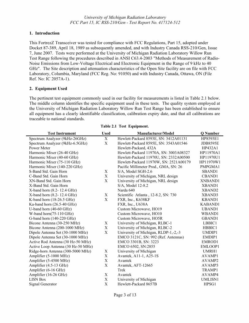
The pertinent test equipment commonly used in our facility for measurements is listed in Table 2.1 below. The middle column identifies the specific equipment used in these tests. The quality system employed at the University of Michigan Radiation Laboratory Willow Run Test Range has been established to ensure all equipment has a clearly identifiable classification, calibration expiry date, and that all calibrations are traceable to national standards.
Table 2.1 Test Equipment.
Test Instrument Used Manufacturer/Model Q Number Spectrum Analyzer (9kHz-26GHz) X Hewlett-Packard 8593E, SN: 3412A01131 HP8593E1 Spectrum Analyzer (9kHz-6.5GHz) X Hewlett-Packard 8595E, SN: 3543A01546 JDB8595E Power Meter Hewlett-Packard, 432A HP432A1 Harmonic Mixer (26-40 GHz) Hewlett-Packard 11970A, SN: 3003A08327 HP11970A1 Harmonic Mixer (40-60 GHz) Hewlett-Packard 11970U, SN: 2332A00500 HP11970U1 Harmonic Mixer (75-110 GHz) Hewlett-Packard 11970W, SN: 2521A00179 HP11970W1 Harmonic Mixer (140-220 GHz) Pacific Millimeter Prod., GMA, SN: 26 PMPGMA1 S-Band Std. Gain Horn X S/A, Model SGH-2.6 SBAND1 C-Band Std. Gain Horn X University of Michigan, NRL design CBAND1 XN-Band Std. Gain Horn X University of Michigan, NRL design XNBAND1 X-Band Std. Gain Horn S/A, Model 12-8.2 XBAND1 X-band horn (8.2- 12.4 GHz) Narda 640 XBAND2 X-band horn (8.2- 12.4 GHz) X Scientific Atlanta , 12-8.2, SN: 730 XBAND3 K-band horn (18-26.5 GHz) X FXR, Inc., K638KF KBAND1 Ka-band horn (26.5-40 GHz) FXR, Inc., U638A KABAND1 U-band horn (40-60 GHz) Custom Microwave, HO19 UBAND1 W-band horn(75-110 GHz) Custom Microwave, HO10 WBAND1 G-band horn (140-220 GHz) Custom Microwave, HO5R GBAND1 Bicone Antenna (30-250 MHz) X University of Michigan, RLBC-1 LBBIC1 Bicone Antenna (200-1000 MHz) X University of Michigan, RLBC-2 HBBIC1 Dipole Antenna Set (30-1000 MHz) X University of Michigan, RLDP-1,-2,-3 UMDIP1 Dipole Antenna Set (30-1000 MHz) EMCO 3121C, SN: 992 (Ref. Antennas) EMDIP1 Active Rod Antenna (30 Hz-50 MHz) EMCO 3301B, SN: 3223 EMROD1 Active Loop Antenna (30 Hz-50 MHz) EMCO 6502, SN:2855 EMLOOP1 Ridge-horn Antenna (300-5000 MHz) X University of Michigan UMRH1 Amplifier (5-1000 MHz) X Avantek, A11-1, A25-1S AVAMP1 Amplifier (5-4500 MHz) X Avantek AVAMP2 Amplifier (4.5-13 GHz) X Avantek, AFT-12665 AVAMP3 Amplifier (6-16 GHz) Trek TRAMP1 Amplifier (16-26 GHz) X Avantek AVAMP4 LISN Box X University of Michigan UMLISN1 Signal Generator X Hewlett-Packard 8657B HPSG1

University of Michigan Radiation Laboratory FCC Part 15, IC RSS-210/Gen - Test Report No. 417124-512
Page 4 of 13
3. Device Under Test (DUT)
3.1 Description & Block Diagram The DUT is a 908.4 MHz limited modular transceiver designed for Z-wave control and communications systems. The device is a small PCB with fix mounted radio module and antenna, measuring 3.2 x 1.8 x 0.3 cm in dimension. For testing, a generic harness was provided by the manufacturer. The DUT is designed and manufactured by FortrezZ LLC, 520 Aarons Way, Ortonville, MI 48462.
Device [Make], Model [S/N],P/N EMC Consideration DUT [FortrezZ], Z3US [US #1] FCC+IC DUT [FortrezZ], Z3US [US #3] FCC+IC DUT [FortrezZ], Z3US [US #5] FCC+IC DUT [FortrezZ], Z3US [US #7] FCC+IC DC wall adapter [Panasonic], PQLV1 9930 9 VDC, 500 mA Cable [Make], Model Length EMC Consideration Battery leads [Generic] 4.0 cm Radiated DC power line [Generic] 1.0 m Conducted
3.2 Variants & Samples There is only a single variant of the device under test. Four working samples were provided for testing; one CW sample, one receive-only sample, one minimum data rate sample and one maximum data rate sample. One sample was provided for photographs, with components removed. Samples were tested for radiated emissions while employing a 9 VDC battery.
3.3 Modes of Operation The device under test is capable of only a single mode of operation, as described in this report. A worst-case continuous transmission data stream was employed for certification to ensure that variations in data packet transmission length could not cause the device to fail regulatory limits. Worst case emission bandwidth was recorded at the maximum data rate of 40 kbps. The device is capable of conducted output power settings between -22 dBm and -2dBm. It was fully tested at its highest possible power setting (-2 dBm) to ensure compliance.
3.4 Exemptions None.
3.5 EMC Relevant Modifications No EMI Relevant Modifications were performed by this test laboratory.

University of Michigan Radiation Laboratory FCC Part 15, IC RSS-210/Gen - Test Report No. 417124-512
Page 5 of 13
4. Emissions Limits
4.1 Radiated Emissions Limits The DUT tested falls under the category of an Intentional Radiator. The applicable testing frequencies and corresponding emission limits set by both the FCC and IC are given in Tables 4.1 and 4.2 below. Table 4.1. TX Emission Limits (FCC: 15.249; IC: RSS-210e A2.9).
Frequency (MHz)
Field Strength of Fundamental (mV/m)
Field Strength of Harmonics (µV/m)
902.0 – 928.0 50 500 2400 - 2483.5 50 500
5725.0 – 5875.0 50 500 24000.0 – 24250.0 250 2500
1) Field strength limits are specified at a distance of 3 meters. 2) Emissions radiated outside of the specified frequency bands, except for harmonics,
shall be attenuated by at least 50 dB below the level of the fundamental or to the general radiated emission limits in Section 15.209 (Class B), whichever is the lesser attenuation.
3) Peak field strength of any emission above 1GHz shall not exceed the maximum permitted average limits specified above by more than 20 dB under any condition of modulation. (15.35)
Table 4.2. Spurious Emission Limits (FCC: 15.33, .35, .109/209; IC: RSS-210 2.7, T2)
Freq. (MHz) Elim (3m) µV/m Elim dB(µV/m) 30-88 100 40.0
88-216 150 43.5 216-960 200 46.0
960-2000 500 54.0 Note: Average readings apply above 1000 MHz (1 MHz BW), Quasi-Peak readings apply to 1000 MHz (120 kHz RBW), PRF of intentional emissions > 20 Hz for QPK to apply.
4.2 Power Line Conducted Emissions Limits Table 4.3 Emission Limits (FCC:15.107 (CISPR); IC: RSS-Gen, 7.2.2 T2).
Frequency Class A (dBμV) Class B (dBμV) (MHz) Quasi-peak Average Quasi-peak Average
.150 - 0.50 79 66 66 - 56* 56 - 46* 0.50 - 5 73 60 56 46 5 - 30 73 60 60 50
Notes: 1. The lower limit shall apply at the transition frequency 2. The limit decreases linearly with the logarithm of the frequency in the range 0.15-0.50 MHz: *Class B Quasi-peak: dBμV = 50.25 - 19.12*log( f ) *Class B Average: dBμV = 40.25 - 19.12*log( f ) 3. 9 kHz RBW

University of Michigan Radiation Laboratory FCC Part 15, IC RSS-210/Gen - Test Report No. 417124-512
Page 6 of 13
5. Measurement Procedures
5.1 Semi-Anechoic Chamber Radiated Emissions To become familiar with the radiated emission behavior of the DUT, the device is first studied and measured in our shielded semi-anechoic chamber. In the chamber there is a set-up similar to that of an outdoor 3-meter site, with a turntable, an antenna mast, and a ground plane. Instrumentation includes spectrum analyzers and other equipment as needed. The DUT is laid on the test table as shown in the included block diagram and/or photographs. A shielded loop antenna is employed when studying emissions from 9 kHz to 30 MHz. Above 30 MHz and below 250 MHz a biconical antenna is employed. Above 250 MHz a ridge or and standard gain horn antennas are used. The spectrum analyzer resolution and video bandwidths are set so as to measure the DUT emission without decreasing the emission bandwidth (EBW) of the device. Emissions are studied for all orientations (3-axes) of the DUT and all test antenna polarizations. In the chamber, spectrum and modulation characteristics of intentional carriers are recorded. Receiver spurious emissions are measured with an appropriate carrier signal applied. Associated test data is presented in subsequent sections.
5.2 Outdoor Radiated Emissions After measurements are performed indoors, emissions on our outdoor 3-meter Open Area Test Site (OATS) are made. If the DUT connects to auxiliary equipment and is table or floor standing, the configurations prescribed in ANSI C63.4 are employed. Alternatively, an on-table layout more representative of actual use may be employed if the resulting emissions appear to be worst-case in such a configuration. Any intentionally radiating elements are placed on the test table flat, on their side, and on their end (3-axes) and worst case emissions are recorded. For each configuration the DUT is rotated 360 degrees about its azimuth and the receive antenna is raised and lowered between 1 and 4 meters to maximize radiated emissions from the device. Receiver spurious emissions are measured with an appropriate carrier signal applied. For devices with intentional emissions below 30 MHz, our shielded loop antenna at a 1 meter received height is used. Low frequency field extrapolation to the regulatory limit distance is employed as needed. Emissions between 30 MHz and 1 GHz are measured using tuned dipoles and/or biconical antennas. Care is taken to ensure that the RBW and VBW used meet the regulatory requirements, and that the EBW of the DUT is not reduced. The Photographs included in this report show the DUT on the OATS.
5.3 Radiated Field Computations To convert the dBm values measured on the spectrum analyzer to dB(µV/m), we use expression E3(dBµV/m) = 107 + PR + KA - KG + KE - CF where PR = power recorded on spectrum analyzer, dB, measured at 3 m KA = antenna factor, dB/m KG = pre-amplifier gain, including cable loss, dB KE = duty correction factor, dB CF = distance conversion (employed only if limits are specified at alternate distance), dB When presenting the data at each frequency, the highest measured emission under all of the possible DUT orientations (3-axes) is given.
5.4 Indoor Power Line Conducted Emissions When applicable, power line conducted emissions are measured in our semi-anechoic chamber. If the DUT connects to auxiliary equipment and is table or floor standing, the configurations prescribed in ANSI C63.4 are employed. Alternatively, an on-table layout more representative of actual use may be employed if the resulting emissions appear to be worst-case in such a configuration.
University of Michigan Radiation Laboratory FCC Part 15, IC RSS-210/Gen - Test Report No. 417124-512
Page 7 of 13
The conducted emissions measured with the spectrum analyzer and recorded (in dBµV) from 0-2 MHz and 2-30 MHz for both the ungrounded (Hi) and grounded (Lo) conductors. The spectrum analyzer is set to peak-hold mode in order to record the highest peak throughout the course of functional operation. Only when the emission exceeds or is near the limit are quasi-peak and average detection used.
5.5 Supply Voltage Variation Measurements of the variation in the fundamental radiated emission were performed with the supply voltage varied by no less than 85% and 115% of the nominal rated value. For battery operated equipment, tests were performed using a new battery, and worst case emissions are re-checked employing a new battery.
6. Test Results
6.1 Radiated Emissions
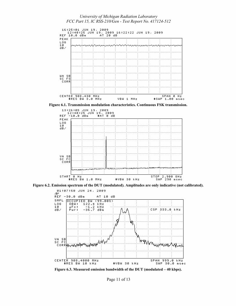
6.1.1 Peak to Quasi-peak and Average Ratio When the transmitter is employed, it can, in the worst case, transmit a continuously modulated FSK waveform. See Figure 6.1. Thus, no duty cycle is employed when verifying compliance for this device.
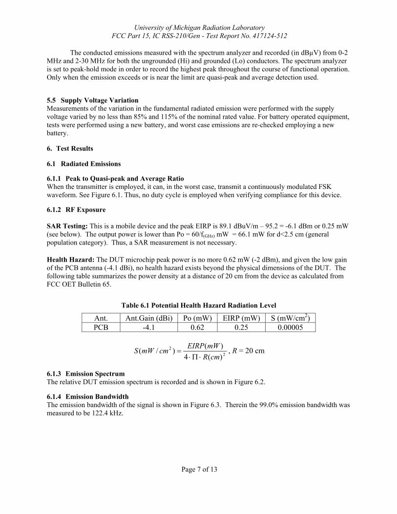
6.1.2 RF Exposure SAR Testing: This is a mobile device and the peak EIRP is 89.1 dBuV/m – 95.2 = -6.1 dBm or 0.25 mW (see below). The output power is lower than Po = 60/f(GHz) mW = 66.1 mW for d<2.5 cm (general population category). Thus, a SAR measurement is not necessary. Health Hazard: The DUT microchip peak power is no more 0.62 mW (-2 dBm), and given the low gain of the PCB antenna (-4.1 dBi), no health hazard exists beyond the physical dimensions of the DUT. The following table summarizes the power density at a distance of 20 cm from the device as calculated from FCC OET Bulletin 65.
Table 6.1 Potential Health Hazard Radiation Level
Ant. Ant.Gain (dBi) Po (mW) EIRP (mW) S (mW/cm2) PCB -4.1 0.62 0.25 0.00005
22
)(4)()/(
cmRmWEIRPcmmWS
⋅Π⋅= , R = 20 cm
6.1.3 Emission Spectrum The relative DUT emission spectrum is recorded and is shown in Figure 6.2.
6.1.4 Emission Bandwidth The emission bandwidth of the signal is shown in Figure 6.3. Therein the 99.0% emission bandwidth was measured to be 122.4 kHz.

University of Michigan Radiation Laboratory FCC Part 15, IC RSS-210/Gen - Test Report No. 417124-512
Page 8 of 13
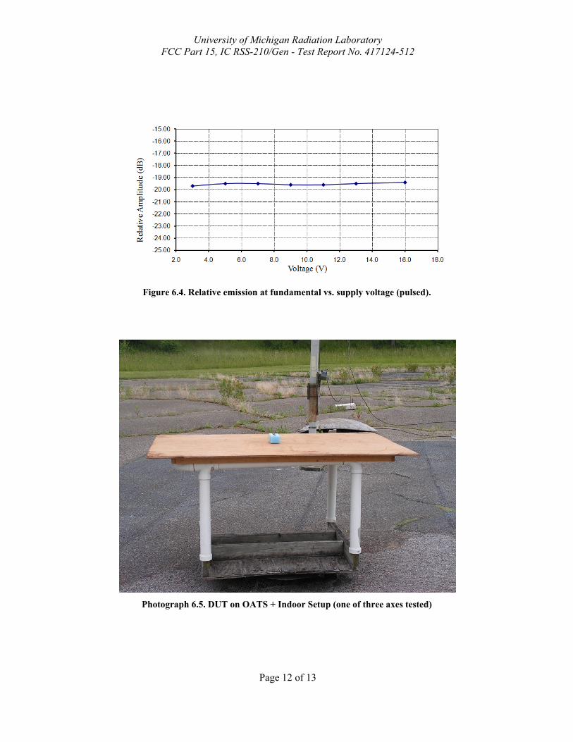
6.1.5 Supply Voltage and Supply Voltage Variation The DUT has been designed to be powered by a 3 to 16 VDC supply or battery. For this test, relative radiated power was measured at the fundamental as the voltage was varied from 3.0 to 16.0 volts using a linear, unfiltered wall supply. The emission variation is shown in Figure 6.4. Batteries: before testing Voc = 9.3 V after testing Voc = 8.7 V Ave. current from batteries I = 25 mA (cw)
6.2 Conducted Emissions AC Mains power line conducted emissions meet the Class B limits by 13.1 dB. Worst case emissions are reported in Table 6.2 and were measured employing a linear, unfiltered DC wall transformer.
The University of Michigan Radiation Laboratory 3228 EECS Building
Ann Arbor, MI 48109-2122 Tel: (734) 764-0500 Fax: (734) 647-2106
FortrezZ Z3X; FCC/ICFreq. Ant. Ant. Pr. (PK) Det.** Ka Kg E3* E3lim Pass
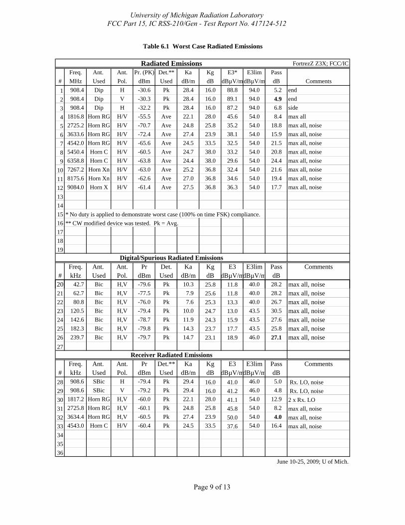
# MHz Used Pol. dBm Used dB/m dB dBµV/mdBµV/m dB Comments1 908.4 Dip H -30.6 Pk 28.4 16.0 88.8 94.0 5.2 end2 908.4 Dip V -30.3 Pk 28.4 16.0 89.1 94.0 4.9 end3 908.4 Dip H -32.2 Pk 28.4 16.0 87.2 94.0 6.8 side4 1816.8 Horn RG H/V -55.5 Ave 22.1 28.0 45.6 54.0 8.4 max all5 2725.2 Horn RG H/V -70.7 Ave 24.8 25.8 35.2 54.0 18.8 max all, noise6 3633.6 Horn RG H/V -72.4 Ave 27.4 23.9 38.1 54.0 15.9 max all, noise7 4542.0 Horn RG H/V -65.6 Ave 24.5 33.5 32.5 54.0 21.5 max all, noise8 5450.4 Horn C H/V -60.5 Ave 24.7 38.0 33.2 54.0 20.8 max all, noise9 6358.8 Horn C H/V -63.8 Ave 24.4 38.0 29.6 54.0 24.4 max all, noise
10 7267.2 Horn Xn H/V -63.0 Ave 25.2 36.8 32.4 54.0 21.6 max all, noise11 8175.6 Horn Xn H/V -62.6 Ave 27.0 36.8 34.6 54.0 19.4 max all, noise12 9084.0 Horn X H/V -61.4 Ave 27.5 36.8 36.3 54.0 17.7 max all, noise131415 * No duty is applied to demonstrate worst case (100% on time FSK) compliance.16 ** CW modified device was tested. Pk = Avg.171819
Freq. Ant. Ant. Pr Det. Ka Kg E3 E3lim Pass Comments# kHz Used Pol. dBm Used dB/m dB dBµV/mdBµV/m dB
Table 6.1 Worst Case Radiated Emissions
Radiated Emissions
Digital/Spurious Radiated Emissions
20 42.7 Bic H,V -79.6 Pk 10.3 25.8 11.8 40.0 28.2 max all, noise21 62.7 Bic H,V -77.5 Pk 7.9 25.6 11.8 40.0 28.2 max all, noise22 80.8 Bic H,V -76.0 Pk 7.6 25.3 13.3 40.0 26.7 max all, noise23 120.5 Bic H,V -79.4 Pk 10.0 24.7 13.0 43.5 30.5 max all, noise24 142.6 Bic H,V -78.7 Pk 11.9 24.3 15.9 43.5 27.6 max all, noise25 182.3 Bic H,V -79.8 Pk 14.3 23.7 17.7 43.5 25.8 max all, noise26 239.7 Bic H,V -79.7 Pk 14.7 23.1 18.9 46.0 27.1 max all, noise27
Freq. Ant. Ant. Pr Det.** Ka Kg E3 E3lim Pass Comments# kHz Used Pol. dBm Used dB/m dB dBµV/mdBµV/m dB28 908.6 SBic H -79.4 Pk 29.4 16.0 41.0 46.0 5.0 Rx. LO, noise29 908.6 SBic V -79.2 Pk 29.4 16.0 41.2 46.0 4.8 Rx. LO, noise30 1817.2 Horn RG H,V -60.0 Pk 22.1 28.0 41.1 54.0 12.9 2 x Rx. LO31 2725.8 Horn RG H,V -60.1 Pk 24.8 25.8 45.8 54.0 8.2 max all, noise32 3634.4 Horn RG H,V -60.5 Pk 27.4 23.9 50.0 54.0 4.0 max all, noise33 4543.0 Horn C H/V -60.4 Pk 24.5 33.5 37.6 54.0 16.4 max all, noise343536
June 10-25, 2009; U of Mich.
Receiver Radiated Emissions
University of Michigan Radiation Laboratory FCC Part 15, IC RSS-210/Gen - Test Report No. 417124-512
Page 9 of 13
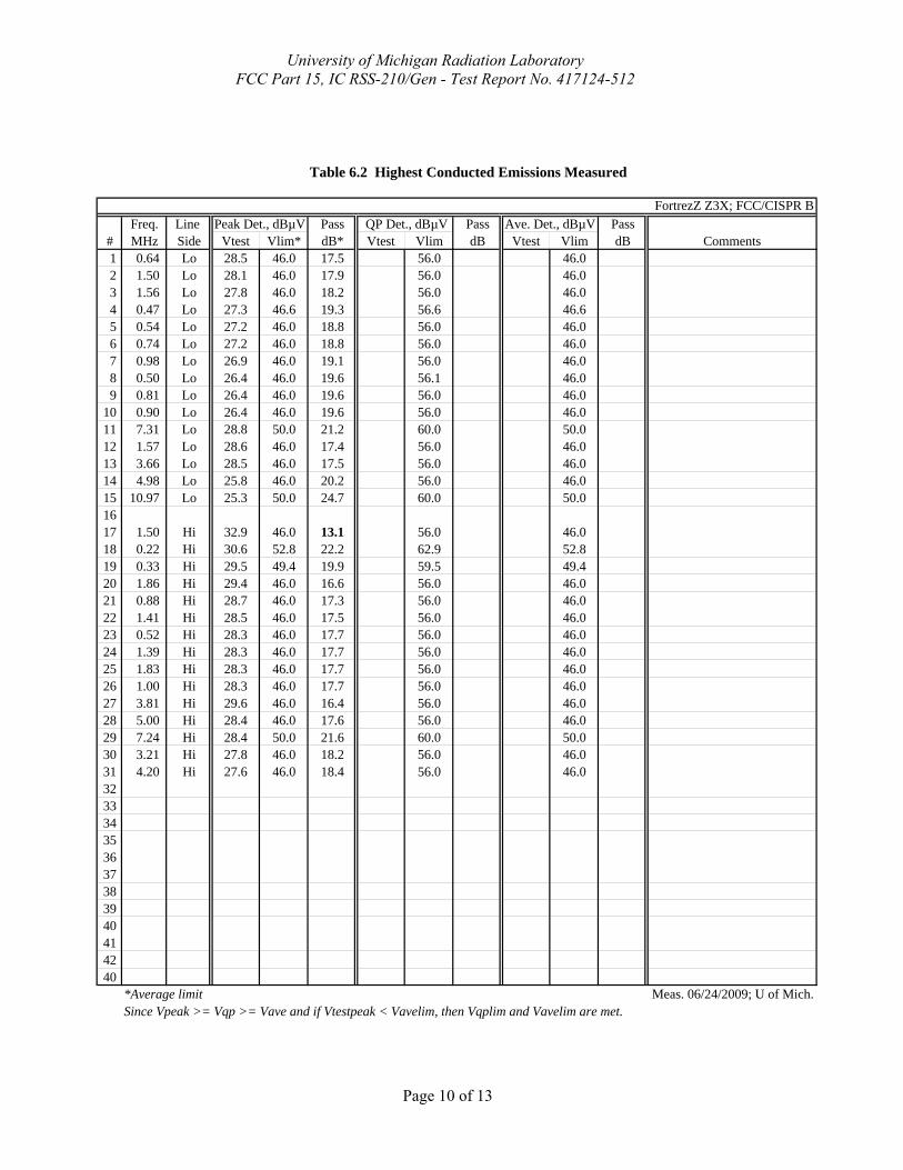
Freq. Line Pass Pass Pass# MHz Side Vtest Vlim* dB* Vtest Vlim dB Vtest Vlim dB Comments1 0.64 Lo 28.5 46.0 17.5 56.0 46.02 1.50 Lo 28.1 46.0 17.9 56.0 46.0 3 1.56 Lo 27.8 46.0 18.2 56.0 46.0 4 0.47 Lo 27.3 46.6 19.3 56.6 46.6 5 0.54 Lo 27.2 46.0 18.8 56.0 46.0 6 0.74 Lo 27.2 46.0 18.8 56.0 46.0 7 0.98 Lo 26.9 46.0 19.1 56.0 46.0 8 0.50 Lo 26.4 46.0 19.6 56.1 46.0 9 0.81 Lo 26.4 46.0 19.6 56.0 46.0
10 0.90 Lo 26.4 46.0 19.6 56.0 46.0 11 7.31 Lo 28.8 50.0 21.2 60.0 50.0 12 1.57 Lo 28.6 46.0 17.4 56.0 46.0 13 3.66 Lo 28.5 46.0 17.5 56.0 46.0 14 4.98 Lo 25.8 46.0 20.2 56.0 46.0 15 10.97 Lo 25.3 50.0 24.7 60.0 50.0 1617 1.50 Hi 32.9 46.0 13.1 56.0 46.0 18 0.22 Hi 30.6 52.8 22.2 62.9 52.8 19 0.33 Hi 29.5 49.4 19.9 59.5 49.4 20 1.86 Hi 29.4 46.0 16.6 56.0 46.0 21 0.88 Hi 28.7 46.0 17.3 56.0 46.0 22 1.41 Hi 28.5 46.0 17.5 56.0 46.0 23 0.52 Hi 28.3 46.0 17.7 56.0 46.0 24 1.39 Hi 28.3 46.0 17.7 56.0 46.0 25 1.83 Hi 28.3 46.0 17.7 56.0 46.0 26 1.00 Hi 28.3 46.0 17.7 56.0 46.0 27 3.81 Hi 29.6 46.0 16.4 56.0 46.0 28 5.00 Hi 28.4 46.0 17.6 56.0 46.0 29 7.24 Hi 28.4 50.0 21.6 60.0 50.0 30 3.21 Hi 27.8 46.0 18.2 56.0 46.031 4.20 Hi 27.6 46.0 18.4 56.0 46.0323334353637 38 39 40 41 42 40
Since Vpeak >= Vqp >= Vave and if Vtestpeak < Vavelim, then Vqplim and Vavelim are met.
Table 6.2 Highest Conducted Emissions Measured
FortrezZ Z3X; FCC/CISPR B Peak Det., dBµV QP Det., dBµV Ave. Det., dBµV
*Average limit Meas. 06/24/2009; U of Mich.
University of Michigan Radiation Laboratory FCC Part 15, IC RSS-210/Gen - Test Report No. 417124-512
Page 10 of 13
University of Michigan Radiation Laboratory FCC Part 15, IC RSS-210/Gen - Test Report No. 417124-512
Page 11 of 13
Figure 6.1. Transmission modulation characteristics. Continuous FSK transmission.
Figure 6.2. Emission spectrum of the DUT (modulated). Amplitudes are only indicative (not calibrated).
Figure 6.3. Measured emission bandwidth of the DUT (modulated – 40 kbps).
University of Michigan Radiation Laboratory FCC Part 15, IC RSS-210/Gen - Test Report No. 417124-512
Page 12 of 13
Figure 6.4. Relative emission at fundamental vs. supply voltage (pulsed).
Photograph 6.5. DUT on OATS + Indoor Setup (one of three axes tested)
University of Michigan Radiation Laboratory FCC Part 15, IC RSS-210/Gen - Test Report No. 417124-512
Page 13 of 13
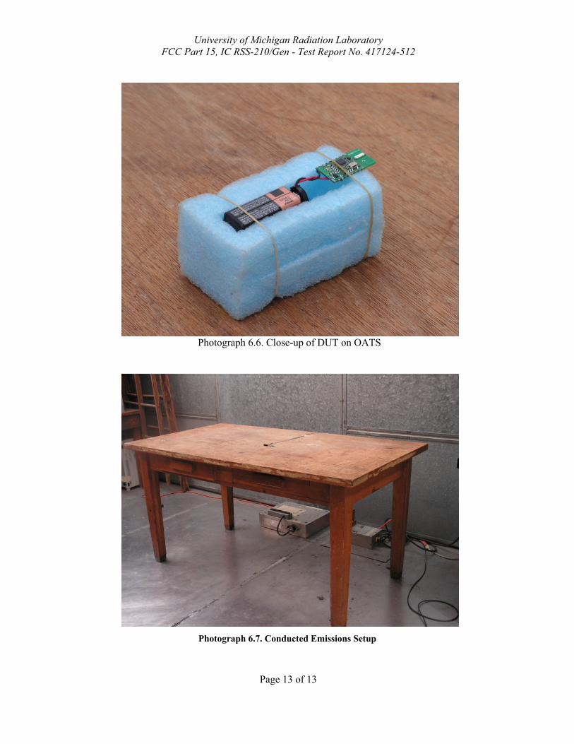
Photograph 6.6. Close-up of DUT on OATS
Photograph 6.7. Conducted Emissions Setup