FortiPlanner 2.0 User Guide - Fortinet Docs...
21
FortiPlanner™ v2.0 User Guide
-
Upload
truongkhue -
Category
Documents
-
view
219 -
download
0
Transcript of FortiPlanner 2.0 User Guide - Fortinet Docs...

FortiPlanner™ v2.0User Guide

FortiPlanner™ v2.0 User Guide
May 5, 2014
29-200-141393-20140505
Copyright© 2014 Fortinet, Inc. All rights reserved. Fortinet®, FortiGate®, FortiCare® and
FortiGuard®, and certain other marks are registered trademarks of Fortinet, Inc., and other
Fortinet names herein may also be registered and/or common law trademarks of Fortinet. All
other product or company names may be trademarks of their respective owners. Performance
and other metrics contained herein were attained in internal lab tests under ideal conditions,
and actual performance and other resultsmay vary. Network variables, different network
environments and other conditions may affect performance results. Nothing herein represents
any binding commitment by Fortinet, and Fortinet disclaims all warranties, whether express or
implied, except to the extent Fortinet enters a binding written contract, signed by Fortinet’s
General Counsel, with a purchaser that expressly warrants that the identified product will
perform according to certain expressly-identified performance metrics and, in such event, only
the specific performance metrics expressly identified in such binding written contract shall be
binding on Fortinet. For absolute clarity, any such warranty will be limited to performance in the
same ideal conditions as in Fortinet’s internal lab tests. Fortinet disclaims in full any covenants,
representations,and guarantees pursuant hereto, whether express or implied. Fortinet reserves
the right to change, modify, transfer, or otherwise revise this publication without notice, and the
most current version of the publication shall be applicable.
Technical Documentation docs.fortinet.com
Knowledge Base kb.fortinet.com
Customer Service & Support support.fortinet.com
Training Services training.fortinet.com
FortiGuard fortiguard.com
Document Feedback [email protected]

Fortinet Technologies Inc. Page 3 FortiPlanner™ v2.0 User Guide
ContentsUsing the FortiPlanner tool.............................................................................. 4
Overview .................................................................................................................. 4
Licensing............................................................................................................ 4
Signal strength displays..................................................................................... 5
FortiPlanner controls.......................................................................................... 5
Drawing the floor plan.............................................................................................. 7
Placing APs for optimal coverage............................................................................ 9
Access point parameters ................................................................................... 9
Placing APs automatically................................................................................ 10
Placing APs manually....................................................................................... 12
Adjusting AP parameters after placement ....................................................... 12
Creating multi-floor or multi-building plans ..................................................... 13
Viewing the results................................................................................................. 13
Creating a report.................................................................................................... 13
Creating a Site Survey.................................................................................... 15
Configuring FortiAP units for test survey mode..................................................... 15
Creating a Site Survey ........................................................................................... 16
Viewing the site survey .................................................................................... 16
Printing a site survey........................................................................................ 17
Monitoring WiFi Coverage ............................................................................. 18
Creating a Live Survey........................................................................................... 18
Creating a FortiPlanner project ........................................................................ 18
Adding FortiGate units to your project............................................................. 19
Adding managed APs to the floor plan............................................................ 20
Viewing the results ........................................................................................... 20
Rogue detection .................................................................................................... 21
Viewing the Rogue list...................................................................................... 21
Printing a report of suspected rogue APs........................................................ 21

Using the FortiPlanner tool
This document explains how to use Fortinet FortiPlanner, a Wi-Fi planning tool that helps you to
determine the optimal placement of FortiAP wireless access points on your premises.
The following topics are included in this section
• Overview
• Drawing the floor plan
• Placing APs for optimal coverage
• Viewing the results
• Creating a report
Overview
Starting with a floor plan of the area that you want to cover with your wireless network, the
planning tool will provide a color-shaded image predicting the expected signal strength
throughout the coverage area. Using the tool, you can try out different placements of wireless
access points prior to installation on the premises.
The overall process for using the planning tool is as follows:
• Draw a floor plan of the coverage area.
• Place APs on your floor plan.
• Run a propagation prediction.
The last two steps are iterative. If the prediction shows some areas with poor coverage, you can
change the placement of your APs and run another propagation prediction.
After you have implemented your wireless network, you can
• Monitor the AP transmit power levels and client load.
• Perform a site survey in which you measure the actual received signal strength throughout
the coverage area.
Licensing
The FortiPlanner application that you download is locked into demo mode. Some features, such
as Site Survey and Real Time Heat Map, are not available until you purchase a license from
Fortinet. You will need to provide the application’s Hardware ID. To find the Hardware ID, go to
the Project menu, and select License Management.
To apply a license file
1. In to the Project menu, and select License Management.
2. Select Browse and locate the license file in your file system.
If the Browse button is unavailable, the application is already licensed. If you want to replace
the existing license with a new one, select Upgrade first.
3. Select Activate.
Page 4

Signal strength displays
The result of the propagation prediction, site survey, or real-time heat map is a floor plan color
shaded to show signal strengths throughout the area.
Figure 1: Example propagation prediction
You can select from several color gradients. From left to right the colors represent increasing
signal strength. If you select Absolute Range Scale, the range is -95dBm to +20 dBm.
Otherwise the range is from weakest to strongest values calculated or measured. However,
FortiPlanner does not color shade regions where the signal strength is below the Signal Floor or
Receiver Sensitivity setting.
FortiPlanner controls
Floor Plan tab
Select wall/windowtype to draw on floor plan
Project menu
Change wall typeattenuation and color
Fortinet Technologies Inc. Page 5 FortiPlanner™ v2.0 User Guide

WiFi Planner tab
Site Survey tab
This is available only if the FortiPlanner application is licensed.
Live Services tab
This is available only if the FortiPlanner application is licensed.
Select AP type to add Select label
Perform automatic AP placement
Select options
Project menu
information to displayExpand AP types list / reveal Edit Device button for Auto Placement
Modify applicationprofiles
Labelon/off
Fortinet Technologies Inc. Page 6 FortiPlanner™ v2.0 User Guide

Reports tab
Display Properties tab
Status bar
Drawing the floor plan
The floor plan shows not only the shape of the rooms in the coverage area, but also the
materials from which they are constructed. Different materials absorb, refract, and reflect radio
waves to different degrees. The planning tool takes this into account when predicting the
coverage you can expect from a particular placement of wireless access points.
You can use the Floor Planner tab as a blank canvas to draw your plan, or you can import a
bitmap image of a floor plan and use it as a guide as you draw walls, doors, windows, and so
on, carefully selecting the material types from which they are constructed.
To start FortiPlanner
1. On the Start menu, select All Programs > Fortinet Inc. > FortiPlanner 2> FortiPlanner 2.
To start the New Project Wizard
1. From the project menu ( ), select New Project.
Create/print/export reports
Select Wi-Fiband to display
Select Signal or Data Rate display
Adjust balance of backgroundand coverage display
Contour gradient step size
Select display gradient
Absolute (-95 to +20dBm) range
Informational messages, status of last operation,etc.
Fit to pageZoom control
Fortinet Technologies Inc. Page 7 FortiPlanner™ v2.0 User Guide

On the Project menu, select New Project to start the Add to Project wizard. The wizard
requests:
• Project Name
• Region Name
• Building Name and address
• Floor Name
On the Floor Name page, you can select Choose Image to load an image file containing the floor
plan layout. Most common image formats are supported, including JPEG, PNG, GIF, BMP, TIFF,
EMF/WMF. If you do not have a floor plan image, select Default Background instead. You can
draw the floor plan later.
Use these buttons to rotate the image into the best orientation for your
floor plan.
To set the scale
1. Select the Floor Planner tab.
2. On the toolbar, select Set Scale ( ) and draw a line representing a structure of known
length, such as a wall.
3. In the dialog box, enter the length of the structure you drew and then select OK.
You can use either metric or English units.
To draw walls and windows
1. Select the Floor Planner tab.
If necessary, you can zoom in or out on the floor plan using the mouse scroll wheel.
2. On the toolbar, select Add Wall ( ).
3. Select the Wall Type.
4. Place the cursor, drag the mouse and release the button to draw a straight line segment,
such as a wall. To delete a line, right-click it and select Delete.
5. Repeat steps 3 and 4 until you have drawn all of the structural elements of the floor plan with
the appropriate building materials.
To save the project
1. Select Save from the project menu ( ).
You can draw only on the grid lines. The small difference in position between the lines you draw
and the lines in the image file is not significant in the propagation calculations.
Fortinet Technologies Inc. Page 8 FortiPlanner™ v2.0 User Guide

Placing APs for optimal coverage
You can use automatic or manual placement of APs. It is also possible to combine the two
methods: use automatic placement initially and then fine-tune the AP positions manually. The
FortiAP model selected on the Access Points tab is the AP type that will be used in either
automatic or manual AP placement.
Access point parameters
You can adjust the parameters of each AP type prior to placement, or adjust individual APs after
placement.
Name This field defines an identifier for the AP. If used prior to
automatic placement, the name is used as a prefix. Each AP
name will consist of the prefix followed by a number. The
default name is “Access Point”. APs will be named “Access
Point_1”, “Access Point_2” and so on.
Device FortiAP model number.
Radio 1, Radio 2
Frequency Show the frequency band of the radio: 2.4GHz or 5GHz. This
depends on the FortiAP model.
Transmit Power (dBm) The AP transmit power to use in the next analysis.
Orientation Select Vertical or Horizontal. The graphic illustrates the unit
orientation compared to the floor.
Direction (degrees) AP orientation as a compass heading. 0 is North, 90 is East,
180 is South, 270 is West.
The parameters are:
Fortinet Technologies Inc. Page 9 FortiPlanner™ v2.0 User Guide
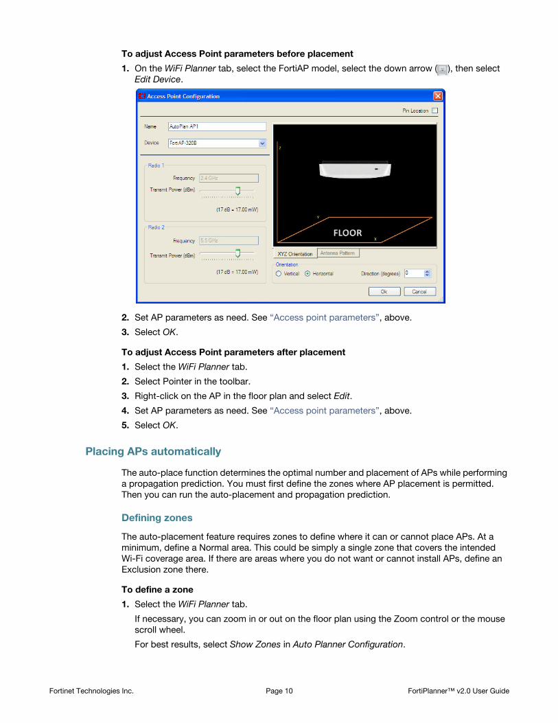
To adjust Access Point parameters before placement
1. On the WiFi Planner tab, select the FortiAP model, select the down arrow ( ), then select
Edit Device.
2. Set AP parameters as need. See “Access point parameters”, above.
3. Select OK.
To adjust Access Point parameters after placement
1. Select the WiFi Planner tab.
2. Select Pointer in the toolbar.
3. Right-click on the AP in the floor plan and select Edit.
4. Set AP parameters as need. See “Access point parameters”, above.
5. Select OK.
Placing APs automatically
The auto-place function determines the optimal number and placement of APs while performing
a propagation prediction. You must first define the zones where AP placement is permitted.
Then you can run the auto-placement and propagation prediction.
Defining zones
The auto-placement feature requires zones to define where it can or cannot place APs. At a
minimum, define a Normal area. This could be simply a single zone that covers the intended
Wi-Fi coverage area. If there are areas where you do not want or cannot install APs, define an
Exclusion zone there.
To define a zone
1. Select the WiFi Planner tab.
If necessary, you can zoom in or out on the floor plan using the Zoom control or the mouse
scroll wheel.
For best results, select Show Zones in Auto Planner Configuration.
Fortinet Technologies Inc. Page 10 FortiPlanner™ v2.0 User Guide

2. In the Coverage Zone list in Auto Planner Configuration, choose:
• Normal - can place APs here
• Limited - coverage desired, but cannot place APs here
• Exclusion - coverage not required, cannot place APs here
3. In the toolbar, select Add Zone ( ).
4. Click to define the starting point, move the mouse to draw. Click when you want to change
the direction of the line. When you have defined a closed area, right-click to stop drawing.
5. Repeat steps 2 through 4 to define additional zones.
Running auto-placement and propagation prediction
With the auto-place zones defined, you can now use the auto-place function. The result is
a propagation prediction with the optimal number and placement of APs.
To place APs automatically and calculate propagation
1. Open your project.
2. Select the WiFi Planner tab.
3. If there are no zones defined, define them now. See “Defining zones” on page 10.
4. In Auto Planner Configuration, select the desired type of coverage (Application) to predict.
The default is Normal Coverage. There are several pre-defined profiles, such as High Priority
Data and VoIP. You can also select Customize to create your own custom profiles. See “To
create custom auto planner profiles” on page 12.
5. In Device, select the type of access point and radio band to use.
6. Select Place Access Points.
FortiPlanner calculates and displays the coverage prediction.
To configure the analysis display parameters
1. With your project open, select the Display Properties tab.
2. In Frequency Band, select either 2.4GHz or 5.0GHz.
3. In View, you can adjust how the signal levels are displayed:
4. In Gradient, select the color spectrum that will represent signal strengths. Optionally you can
enable Absolute Range Scale.
5. In Settings, set
Contour (dBm) Adjusts the step size of the color gradient. For example, a
3dB setting shows a different color for each 3dB change in
signal.
Background Opacity Adjusts how well the background image can be seen
through the coverage shading. 100 maximizes background
visibility but parts of the background may not be visible if
Coverage Opacity is too high.
Coverage Opacity Adjusts how much the coverage shading hides the
background image. 100 maximizes coverage visibility but
might obscure the background.
Display Units Choose English or Metric measurement.
Signal Floor (dBm) Enter the lowest acceptable signal level for your intended
coverage area.
Fortinet Technologies Inc. Page 11 FortiPlanner™ v2.0 User Guide

To create custom auto planner profiles
1. On the WiFi Planner tab, in Auto Planner Configuration, select Customize.
The Auto Planner Profile Configuration window opens.
2. Select New, enter a name for the profile, and then select OK.
3. Enter the following information, select Apply and Exit:
Placing APs manually
Manual AP placement is an iterative process. You put APs on the floor plan and view the
propagation prediction. Then, you try moving the APs or adding additional APs and then
viewing the prediction again to see if you have improved the wireless coverage.
To place APs on the floor plan
1. With your project open, select the Access Points tab.
2. In Wireless Devices, select the type of access point that you want to place.
3. Do any of the following:
• In the toolbar, select Add Device. Click on the floor plan where you want to place an AP.
• Drag an existing AP to a new position.
• Right-click an AP to modify its settings or remove it.
The propagation prediction is updated.
4. Repeat any of the actions in Step 3 as needed to produce the desired coverage.
The Labels button in Wireless Devices toggles AP labels on and off. The drop-down menu on
the Labels button controls which pieces of information are included on the labels.
5. From the project menu ( ), select Save.
Adjusting AP parameters after placement
You can select individual APs and adjust their settings.
To adjust Access Point parameters after placement
1. On either the Floor Plan or WiFi Planner tab, right-click the access point and select Edit.
You must have the Pointer tool selected in the toolbar.
2. Adjust the parameters in the Access Point Configuration window and select OK.
The propagation prediction is updated.
To remove an access point
1. On either the Floor Plan or WiFi Planner tab, right-click the access point and select Delete.
You must have the Pointer tool selected in the toolbar.
Transmit Power (dBm) Make sure that your selected power level does not
exceed the regulatory limits for your region.
Receiver Sensitivity (dBm) Enter the lowest signal level that the AP’s receiver
can receive reliably.
Access Point Orientation Select either Vertical or Horizontal mounting
orientation for the AP unit.
Access Point Coverage
Aggressive
Select to attempt 100% coverage for zones where
coverage is desired. Otherwise, a 90% coverage
target is used. A point is considered covered if the
signal strength exceeds the Receiver Sensitivity.
Fortinet Technologies Inc. Page 12 FortiPlanner™ v2.0 User Guide

Creating multi-floor or multi-building plans
The Project window shows your project as a tree diagram hierarchy of region, building, and floor
elements.
To add an element, you right-click the parent element in the tree, select New and then select
Region, Building, or Floor. For example, to add a floor to a particular building, right-click that
building and select New > Floor.
The Add to Project wizard starts at the selected element level and requests information for that
level and below, as it does when creating a new project. For example, if you select New >
Building, you are also asked for floor information.
To remove any element, right-click it and select Delete.
To rename a floor plan
1. In the Project pane, right-click the floor and select Rename.
Viewing the results
Now you can view the propagation prediction. On the Display Properties tab:
• Select either the 2.4GHz or the 5.0GHz band results.
• Select either Signal Level or Data Rate results.
• Select the color gradient scheme and adjust the gradient step size (Contour (dBm)).
• Adjust the balance between the floor plan background and coverage prediction using the
Background Opacity and Coverage Opacity settings.
• Set the minimum acceptable signal in Signal Floor.
Using the left column, you can select which floor of a multi-floor project to view. Using the
controls at the bottom right of the page, you can zoom in on areas of interest.
Information about each AP is listed, depending on the selections in Labels on the WiFi Planner
tab.
Creating a report
FortiPlanner can create a report with the following optional sections:
• Deployment Placement — your floor plan including access point locations
• Device Placement Detail — name, configuration and location map of each AP
• Device Inventory — list of network APs by model, with count by model
• Propagation Analysis — the propagation prediction for 2.5GHz and/or 5GHz
• Auto Placement Zones — maps of your Normal, Limited, and Exclusion zones
• Site Survey — Site Survey information for a specified SSID
• Rogue Devices — details of detected rogue APs
If there are multiple floors in the project, the selected report sections are generated for each
floor. You can print the report or save it in several different formats.
Fortinet Technologies Inc. Page 13 FortiPlanner™ v2.0 User Guide

To create the report
1. With your project open, select the Reports tab, then select Project Deployment Plan.
2. In the FortiPlanner Reports window, select the report sections that you want to include.
3. Select Generate.
4. The first report is displayed in the Report Preview window.
5. Do any of the following:
• Print the report.
• Save the report. Several output formats are supported. PDF is the default.
6. When you are finished printing or saving the report, close the window.
Fortinet Technologies Inc. Page 14 FortiPlanner™ v2.0 User Guide

Creating a Site Survey
Site Survey enables you to walk about your WiFi coverage area with a portable computer and
measure actual received signal strengths.
Configuring FortiAP units for test survey mode
Before permanent WiFi equipment installation, you can configure FortiAP units in survey mode
and place them temporarily. No FortiGate unit is required. The APs will broadcast a test SSID
whose coverage you can measure with the FortiPlanner application. This allows for fine
adjustments to the AP placements you determined with the WiFi Planner function.
After permanent installation you can perform a site survey to investigate complaints of poor
coverage or to determine where adjustments might be needed after office reconfiguration or
renovation.
To reset the FortiAP unit to factory defaults
1. Connect the power adapter to the FortiAP 12VDC connector and plug in the adapter.
2. Reset the FortiAP to factory defaults. Use a pin to press the reset button until the power light
flashes amber (about 5 seconds).
To prepare the FortiAP
1. Connect an Ethernet cable from the FortiAP RJ-45 connector to the network interface on
your computer.
2. Set the computer’s IP address to 192.168.1.3.
3. Use a browser to connect to 192.168.1.2, the FortiAP unit’s default IP address.
4. On the System Information Tab, in the Network Configuration section, in Administrative
Access, enable TELNET.
5. Using a terminal emulator, connect to 192.168.1.2.
Some terminal emulators: telnet, HyperTerminal, PuTTY.
6. Log in as admin. By default, there is no password.
7. Enter:
cfg -a AP_MODE=2cfg -c
8. Optionally, you can also configure the following parameters:
SURVEY_SSID - default is FAP_SURVEY
SURVEY_TX_POWER - power in dBm, default 30
SURVEY_CH_24 - 2.4GHz band channel
SURVEY_CH_50 - 5GHz band channel
SURVEY_BEACON_INTV - beacon interval
Precede the parameter with cfg -a as was done for AP_MODE in the preceding step. You
can review your settings by entering cfg -s. When you are finished, enter cfg -c to
commit the changes.
Page 15

Creating a Site Survey
The Site Survey is based on signal strength readings that you take with a portable computer as
you move about the coverage area.
To perform a site survey
1. Connect a WLAN adapter to your laptop computer.
2. Start FortiPlanner and go to the Site Survey tab.
3. In Configuration, choose the Wireless Adapter that you connected.
4. Optionally adjust the Range and Waiting Time.
5. In Survey, select New.
6. Click your current location on the floor layout and start walking at a slow steady pace. Click
your location on the floor layout periodically and when you stop, start, or change direction.
During the survey, a point data is recorded each time you click on the floor plan. A green
circle is added, representing the Range setting, default 5 metres. For the most complete
survey, you should click to record another data point when you reach the edge of the
previous data point’s circle.
7. When you have finished walking the coverage area, stop the survey.
A Site Survey result looks like this:
Viewing the site survey
After site survey is completed, you can view the results. The BSSID and SSID's captured during
site survey is shown in the table in lower left hand corner.
To determine coverage for a specific SSID
1. Use the search tool find the SSID of interest.
2. In the table, shift-select all of the instances of that SSID.
To determine if network is ready for voice over wireless
1. Determine the lowest signal that voice handset requires, usually -68dB.
2. Shift-click the SSID of interest.
Fortinet Technologies Inc. Page 16 FortiPlanner™ v2.0 User Guide

3. On the Display Properties menu, set Signal Floor to -68dB.
Only the coverage areas where the signal level is stronger than -68dB are highlighted. Any
uncolored areas have inadequate signal and calls may drop.
Printing a site survey
On the Reports tab, select Project Deployment Plan. Site Survey is one of the optional report
elements.
Fortinet Technologies Inc. Page 17 FortiPlanner™ v2.0 User Guide

Monitoring WiFi Coverage
FortiPlanner can evaluate and monitor the real-world performance of your wireless network,
whether you designed it with FortiPlanner or not. There are two main tools to do this:
• Live Survey retrieves coverage information from the FortiGate WiFi controllers, including
actual transmit power and the number of connected clients. This display is particularly useful
when Auto Tx Power Control is in use.
The following topics are included in this section:
• Creating a Live Survey
• Rogue detection
Creating a Live Survey
The Live Survey or real time heat map is based on information retrieved from the FortiGate units
that manage your access points. FortiPlanner connects automatically to these FortiGate units.
You need to position the FortiAP units on your floor plan corresponding to their actual locations
on your premises.
This section describes how to:
• Create a FortiPlanner project containing a floor plan of the coverage area.
• Add the WiFi controller FortiGate units to your floor plan
• Place the managed APs on your floor plan.
Creating a FortiPlanner project
If you used FortiPlanner to plan your network, you might be able to use that project for the Real
Time Heat Map as well. The floor plan must contain visual landmarks such as walls and
windows on its background. Walls added with the Add Wall function are not visible in the Live
Services display.
Otherwise, create a new project as follows.
To start FortiPlanner
1. On the Start menu, select All Programs > Fortinet Inc. > FortiPlanner 2> FortiPlanner 2.
To start the New Project Wizard
1. From the project menu ( ), select New Project.
On the Project menu, select New Project to start the Add to Project wizard. The wizard
requests:
• Project Name
• Region Name
• Building Name and address
• Floor Name
Page 18

On the Floor Name page, you can select Choose Image to load an image file containing the floor
plan layout. Most common image formats are supported, including JPEG, PNG, GIF, BMP, TIFF,
EMF/WMF.
Use these buttons to rotate the image into the best orientation for your
floor plan.
To set the scale
1. On the toolbar, select Set Scale ( ) and draw a line representing a structure of known
length, such as a wall.
2. In the dialog box, enter the length of the structure you drew and then select OK.
You can use either metric or English units.
To save the project
1. Select Save from the project menu ( ).
Adding FortiGate units to your project
You need to add to your project the FortiGate units that manage your FortiAP units.
To add a FortiGate unit to your project
1. In the Project pane window, right-click the top node and select New > FortiGate.
2. Enter:
3. Select OK.
A new FortiGate node is added to the Project pane. The icon color shows the status of the
FortiGate unit.
Not connected.
Connected.
Name A name to identify this FortiGate unit.
VDOM The virtual domain that applies to the WiFi controller. If you are
not using VDOMs, enter root.
Network address The FortiGate unit’s IP address for administrative access.
Username
Password
The credentials for administrative access to the FortiGate unit.
Fortinet Technologies Inc. Page 19 FortiPlanner™ v2.0 User Guide

Adding managed APs to the floor plan
The Project window lists managed Forti APs under the FortiGate unit that manages them. The
FortiAPs are identified by serial number. To place a FortiAP on your floor plan, drag the FortiAP
icon to the appropriate location on the floor plan. You will need to know the locations where the
APs were installed and the serial number of the unit in each location.
FortiAP units that are already placed on the floor plan are listed in a smaller typeface in the
Project window.
Viewing the results
The coverage display on the Live Services tab is updated after each Refresh Interval. You can
modify the display in several ways:
• In Access Points, you can select which AP information Labels to display.
• You can switch to the Display Properties tab to
• change color gradient
• balance display of background and coverage
• set Signal Floor (minimum acceptable signal)
• On the floor plan, enable Show AP Propagation.
Figure 2: Live Survey Result
Fortinet Technologies Inc. Page 20 FortiPlanner™ v2.0 User Guide

Rogue detection
After you have set up the Live Survey, FortiPlanner receives information about suspected rogue
APs from FortiGate units. A Rogue AP is one that is not managed by any of the FortiGate units
in the FortiPlanner project.
You can:
• View the Rogue list to see the information gathered about suspected rogues.
• Optionally, receive an alert when a rogue AP is detected in alert zones you draw on the floor
plan.
Viewing the Rogue list
The Rogue list is initially empty. Select Refresh at the top left of the Rogue pane to populate the
list.
The list columns show typical WiFi parameters: SSID, MAC address, AP manufacturer, security
mode (such as WPA Auto), received signal strength, radio channel, number of clients (WTPs),
and when the AP was detected. In addition, there is a column that indicates whether the
FortiGate unit considers the suspected rogue to be “on-wire” and therefore a potential security
threat.
Clicking a column header sorts the Rogue table by the content of that column.
Printing a report of suspected rogue APs
On the Reports tab, select Project Deployment Plan. Rogue Devices is one of the optional
report elements.
Fortinet Technologies Inc. Page 21 FortiPlanner™ v2.0 User Guide