![( 11-2-12) Jerz > Writing > Creative [Heller insertions].](https://static.fdocuments.in/doc/165x107/5a4d1b377f8b9ab05999d647/httpjerzsetonhilleduwritingcreative1showing-11-2-12-jerz-writing.jpg)
Forming Processes Chapters 13-16 - University of...
55
© R. Jerz 1 3/20/2006 Forming Processes Chapters 13-16
Transcript of Forming Processes Chapters 13-16 - University of...
© R. Jerz 1 3/20/2006
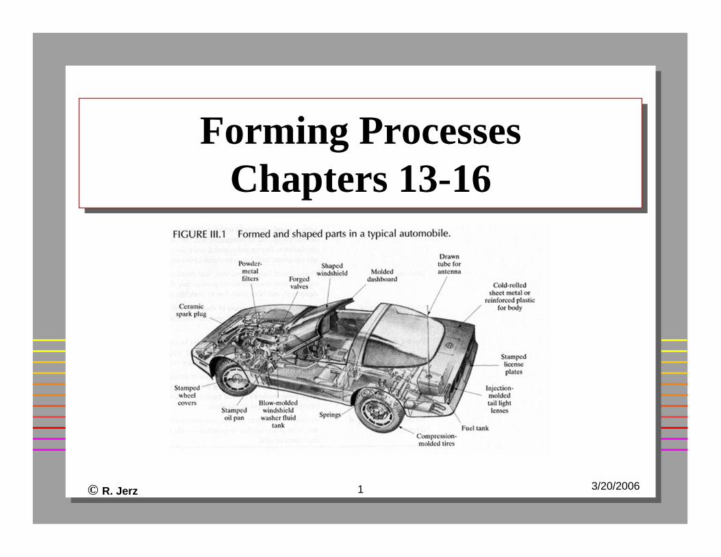
Forming ProcessesChapters 13-16
Forming ProcessesChapters 13-16
© R. Jerz 2 3/20/2006
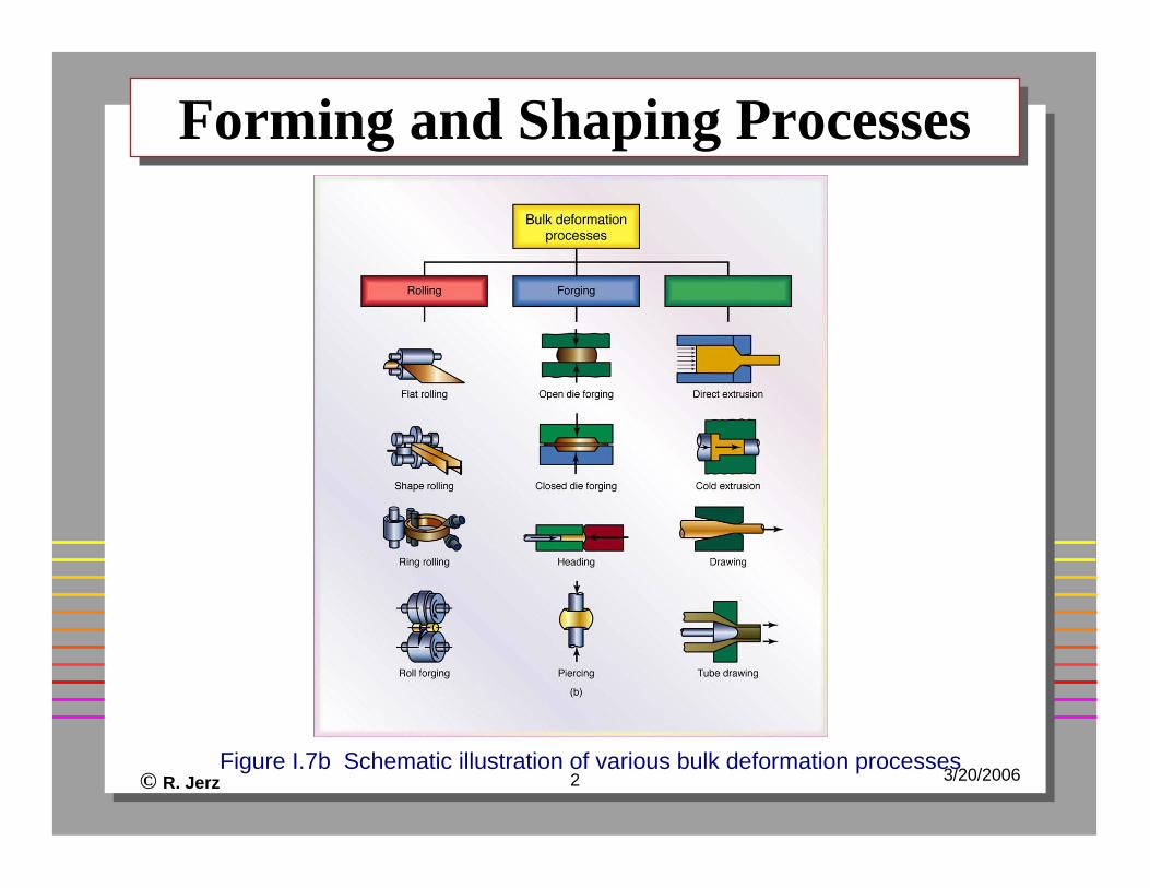
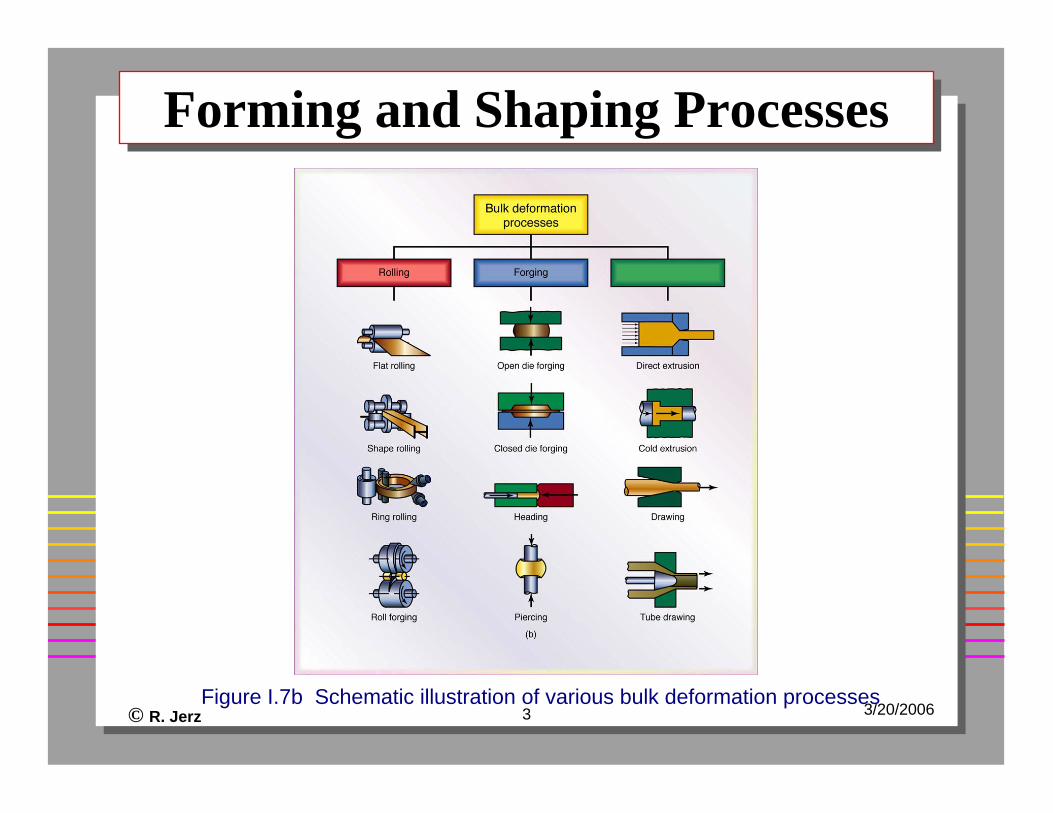
Forming and Shaping ProcessesForming and Shaping Processes
Figure I.7b Schematic illustration of various bulk deformation processes
© R. Jerz 3 3/20/2006
Forming and Shaping ProcessesForming and Shaping Processes
Figure I.7b Schematic illustration of various bulk deformation processes
© R. Jerz 4 3/20/2006
Characteristics of FormingCharacteristics of Forming
Metal flow through forming and shapingLittle wasteHigher capital costHigher volume neededTooling cost is expensive
© R. Jerz 5 3/20/2006
Process VariablesProcess Variables
Starting materialStarting work piece geometryTool or die geometryLubricationStarting temperatureSpeed of operationAmount of deformation
© R. Jerz 6 3/20/2006
Dependent VariablesDependent Variables
Force or power requiredNature of material flowMaterial propertiesExit temperatureSurface finish
© R. Jerz 7 3/20/2006
OutcomeOutcome
ExperienceExperimentTheory
© R. Jerz 8 3/20/2006
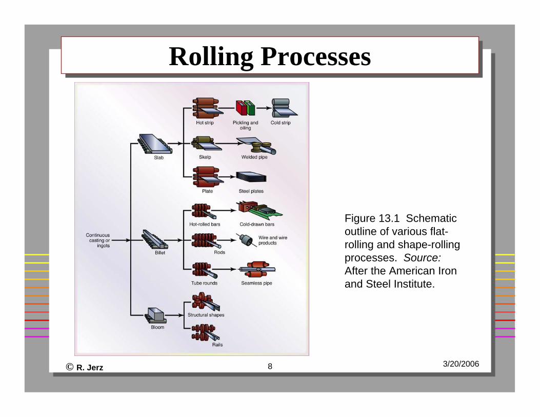
Rolling ProcessesRolling Processes
Figure 13.1 Schematic outline of various flat-rolling and shape-rolling processes. Source:After the American Iron and Steel Institute.
© R. Jerz 9 3/20/2006
Rolling ProcessesRolling Processes
Set of rollsContinuous or discreteCold or hotVariety of shapes depend on rolling diesPart have uniform and dependable quality2% to 5% dimensional tolerance

© R. Jerz 10 3/20/2006
Flat-Rolling ProcessFlat-Rolling Process
© R. Jerz 11 3/20/2006
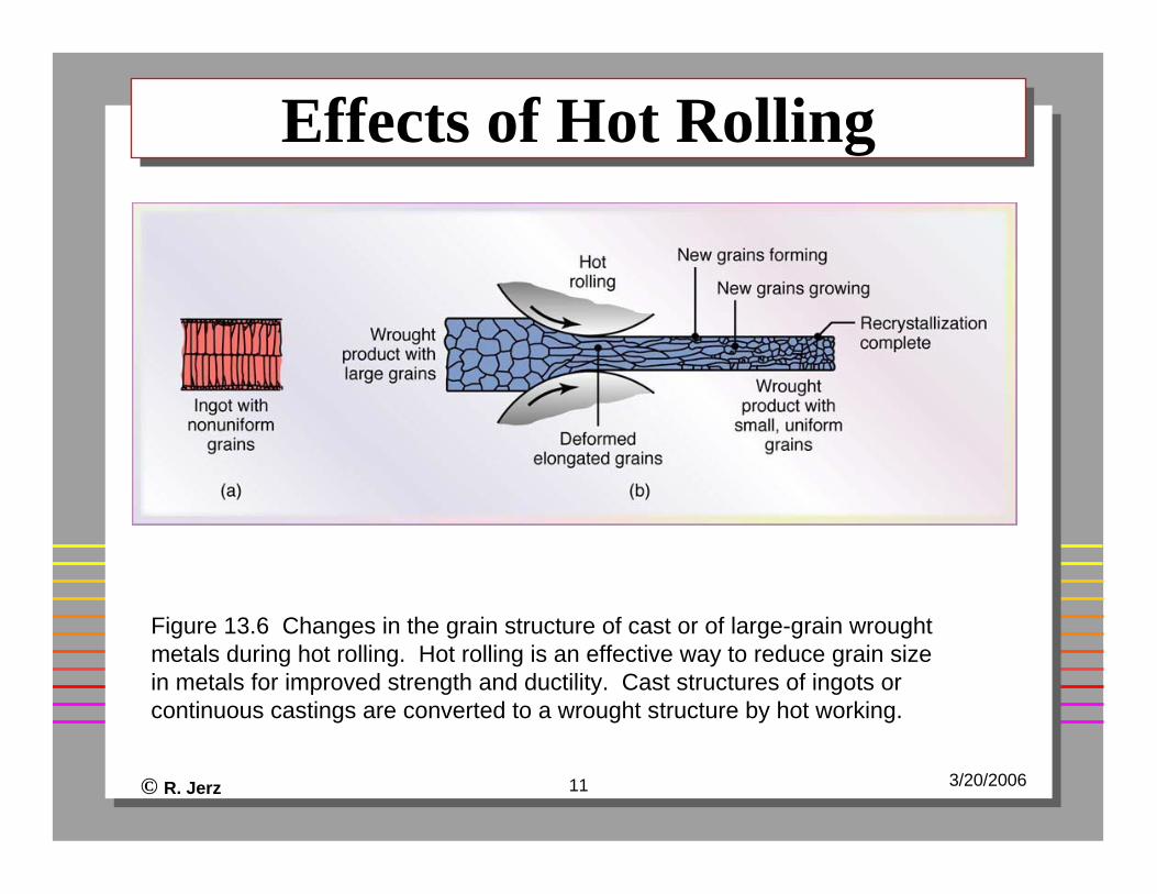
Effects of Hot RollingEffects of Hot Rolling
Figure 13.6 Changes in the grain structure of cast or of large-grain wrought metals during hot rolling. Hot rolling is an effective way to reduce grain size in metals for improved strength and ductility. Cast structures of ingots or continuous castings are converted to a wrought structure by hot working.
© R. Jerz 12 3/20/2006
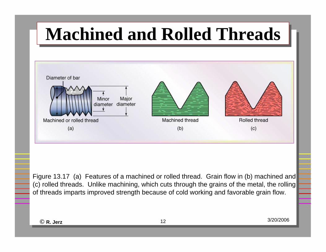
Machined and Rolled ThreadsMachined and Rolled Threads
Figure 13.17 (a) Features of a machined or rolled thread. Grain flow in (b) machined and (c) rolled threads. Unlike machining, which cuts through the grains of the metal, the rolling of threads imparts improved strength because of cold working and favorable grain flow.
© R. Jerz 13 3/20/2006
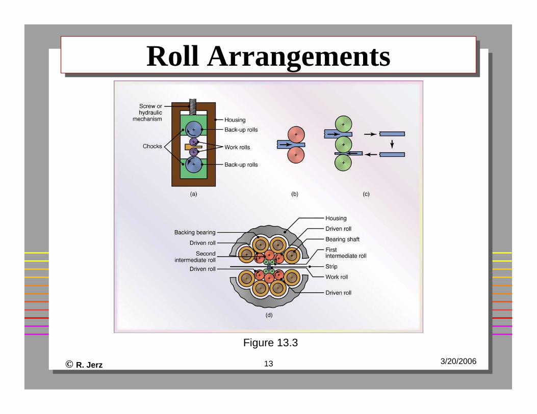
Roll ArrangementsRoll Arrangements
Figure 13.3
© R. Jerz 14 3/20/2006
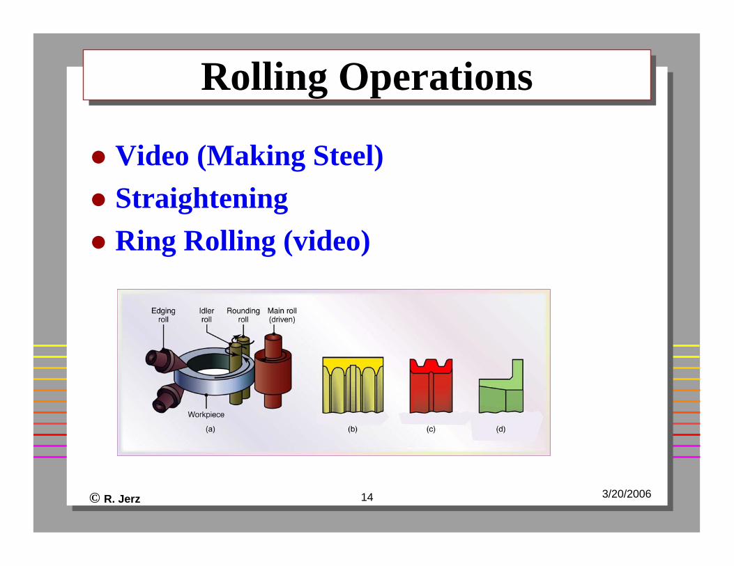
Rolling OperationsRolling Operations
Video (Making Steel)StraighteningRing Rolling (video)
© R. Jerz 15 3/20/2006
Forging of Metals (ch14)Forging of Metals (ch14)
“Blacksmith” (video)Shaping operationCompressive forcesDies (mid to high cost)Discrete raw materialProcess variable (as above)Hot, warm, or cold
© R. Jerz 16 3/20/2006
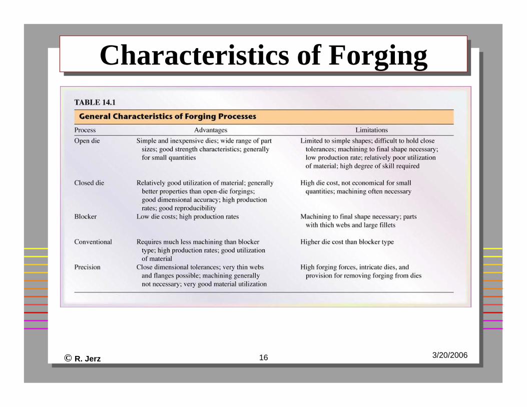
Characteristics of ForgingCharacteristics of Forging
© R. Jerz 17 3/20/2006
Forged ComponentsForged Components
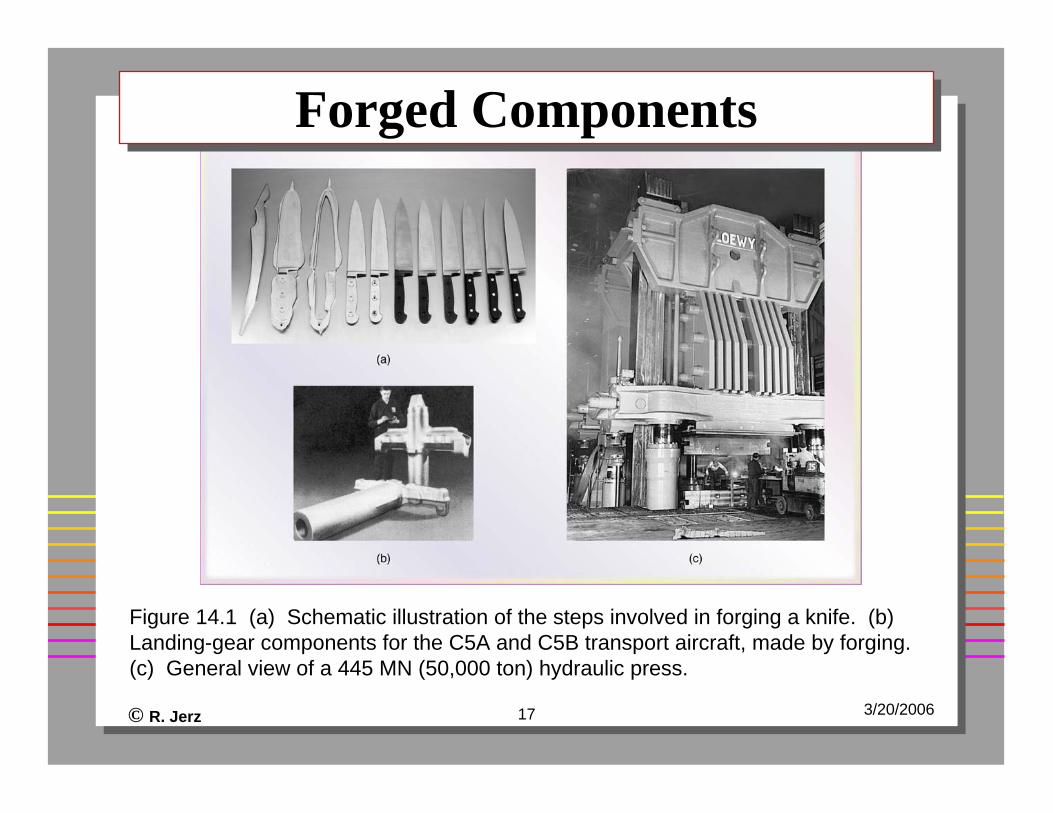
Figure 14.1 (a) Schematic illustration of the steps involved in forging a knife. (b) Landing-gear components for the C5A and C5B transport aircraft, made by forging. (c) General view of a 445 MN (50,000 ton) hydraulic press.
© R. Jerz 18 3/20/2006
Microstructure of PartsMicrostructure of Parts
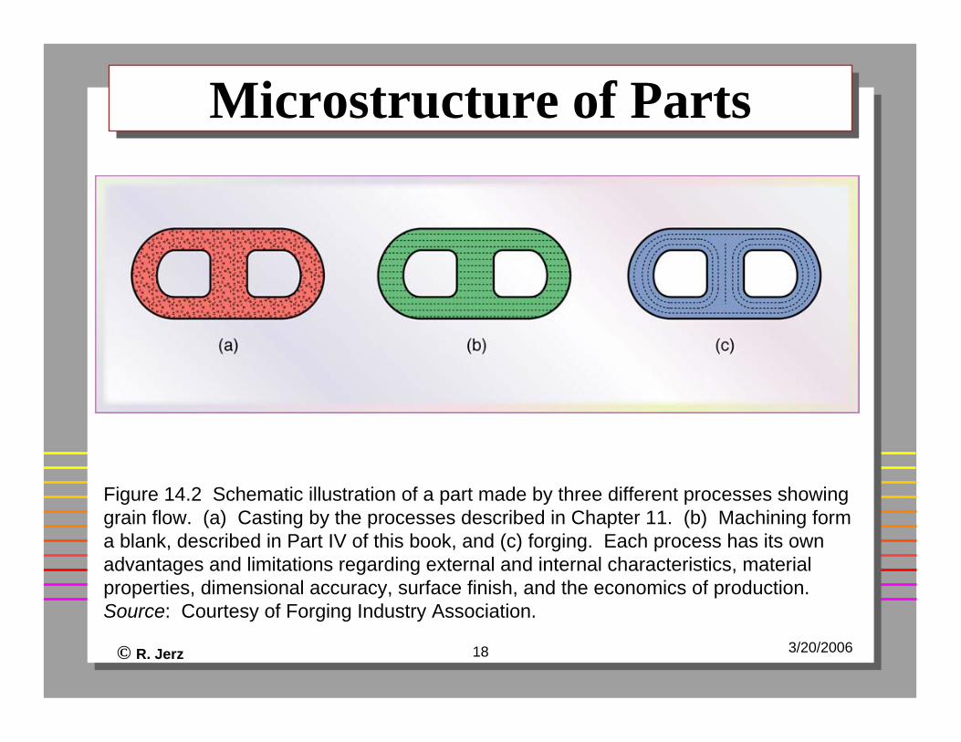
Figure 14.2 Schematic illustration of a part made by three different processes showing grain flow. (a) Casting by the processes described in Chapter 11. (b) Machining form a blank, described in Part IV of this book, and (c) forging. Each process has its own advantages and limitations regarding external and internal characteristics, material properties, dimensional accuracy, surface finish, and the economics of production. Source: Courtesy of Forging Industry Association.
© R. Jerz 19 3/20/2006
Grain Flow in ForgingGrain Flow in Forging
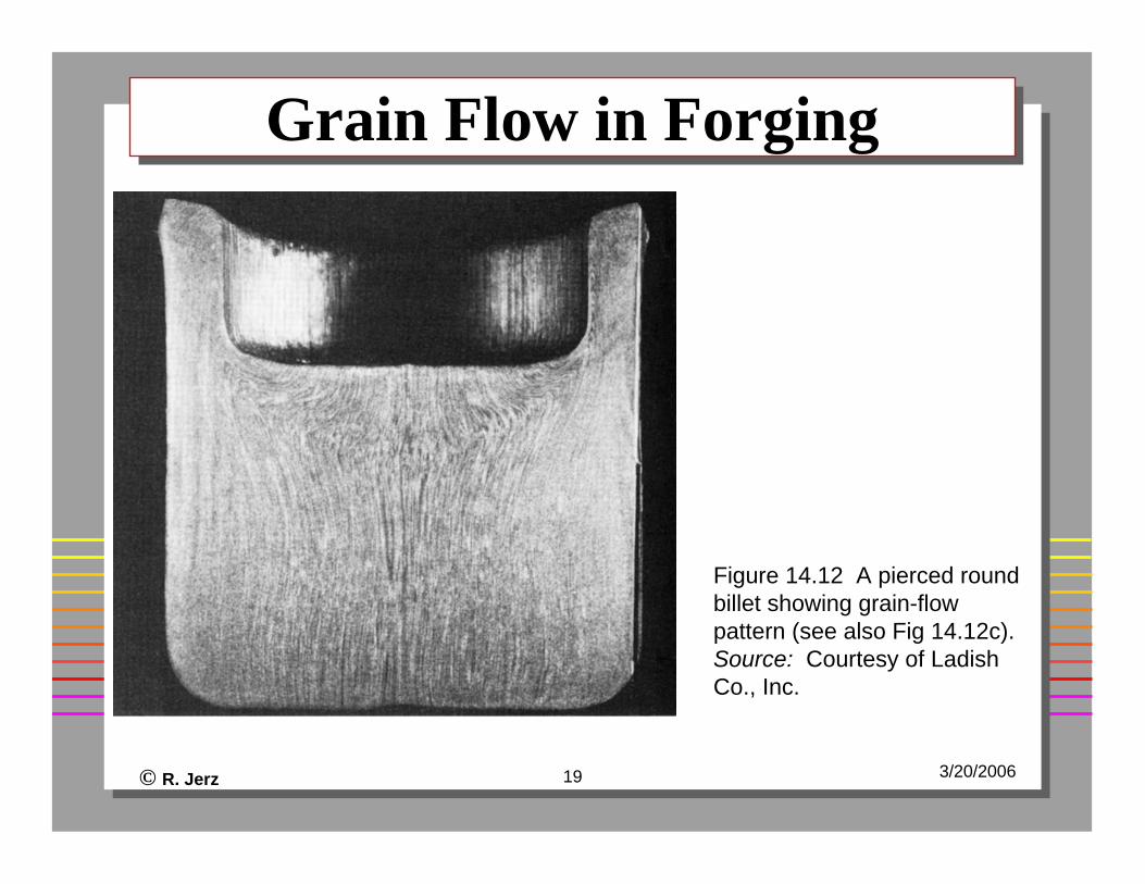
Figure 14.12 A pierced round billet showing grain-flow pattern (see also Fig 14.12c). Source: Courtesy of LadishCo., Inc.
© R. Jerz 20 3/20/2006
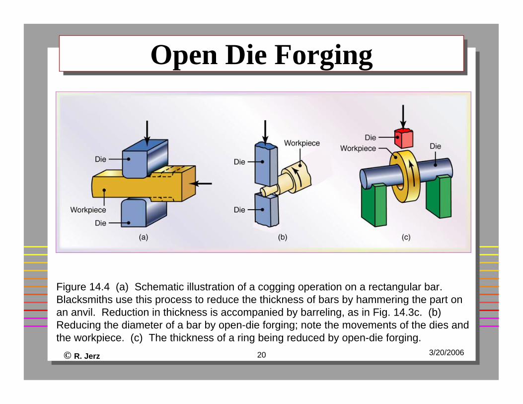
Open Die ForgingOpen Die Forging
Figure 14.4 (a) Schematic illustration of a cogging operation on a rectangular bar. Blacksmiths use this process to reduce the thickness of bars by hammering the part on an anvil. Reduction in thickness is accompanied by barreling, as in Fig. 14.3c. (b) Reducing the diameter of a bar by open-die forging; note the movements of the dies and the workpiece. (c) The thickness of a ring being reduced by open-die forging.
© R. Jerz 21 3/20/2006
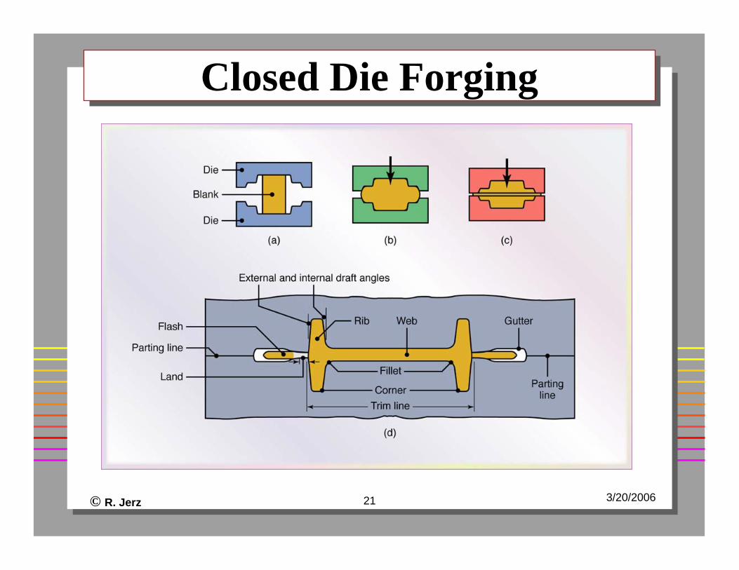
Closed Die ForgingClosed Die Forging
© R. Jerz 22 3/20/2006
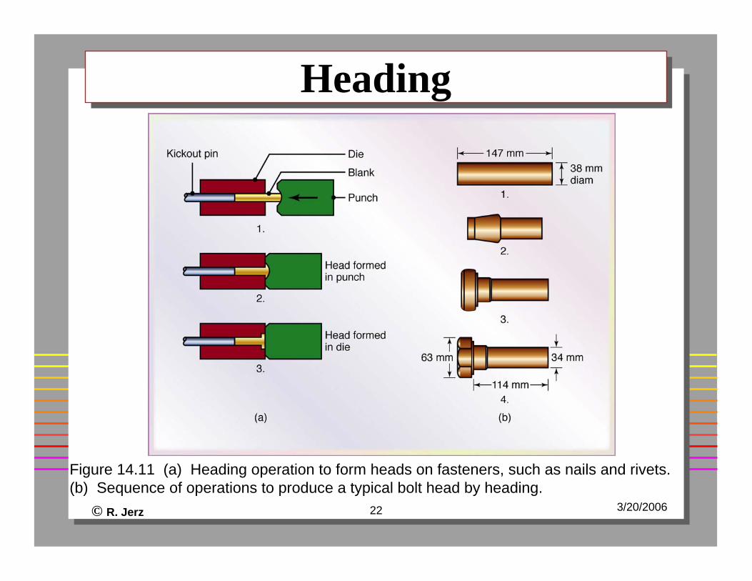
HeadingHeading
Figure 14.11 (a) Heading operation to form heads on fasteners, such as nails and rivets. (b) Sequence of operations to produce a typical bolt head by heading.
© R. Jerz 23 3/20/2006
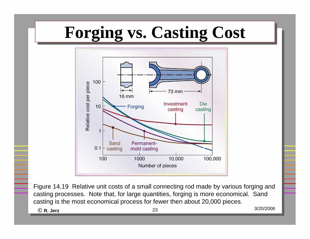
Forging vs. Casting CostForging vs. Casting Cost
Figure 14.19 Relative unit costs of a small connecting rod made by various forging and casting processes. Note that, for large quantities, forging is more economical. Sand casting is the most economical process for fewer then about 20,000 pieces.
© R. Jerz 24 3/20/2006
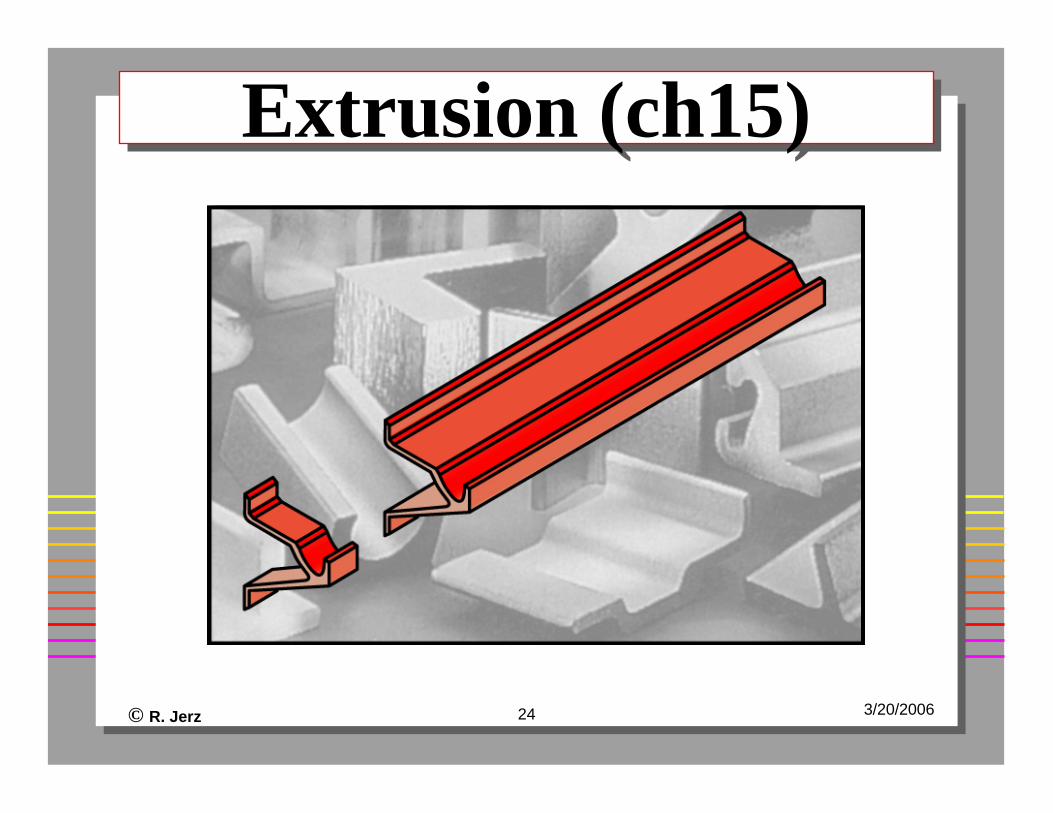
Extrusion (ch15)Extrusion (ch15)
© R. Jerz 25 3/20/2006
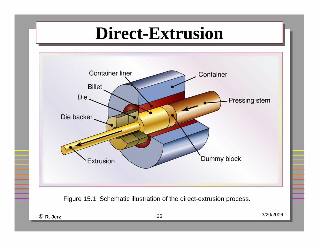
Direct-ExtrusionDirect-Extrusion
Figure 15.1 Schematic illustration of the direct-extrusion process.
© R. Jerz 26 3/20/2006
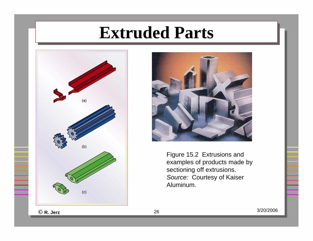
Extruded PartsExtruded Parts
Figure 15.2 Extrusions and examples of products made by sectioning off extrusions. Source: Courtesy of Kaiser Aluminum.
© R. Jerz 27 3/20/2006
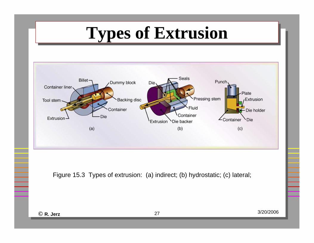
Types of ExtrusionTypes of Extrusion
Figure 15.3 Types of extrusion: (a) indirect; (b) hydrostatic; (c) lateral;
© R. Jerz 28 3/20/2006
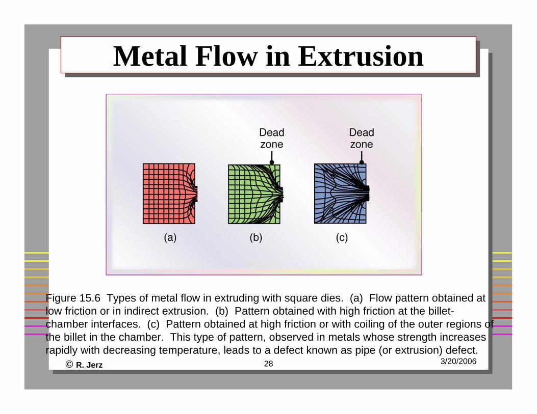
Metal Flow in ExtrusionMetal Flow in Extrusion
Figure 15.6 Types of metal flow in extruding with square dies. (a) Flow pattern obtained at low friction or in indirect extrusion. (b) Pattern obtained with high friction at the billet-chamber interfaces. (c) Pattern obtained at high friction or with coiling of the outer regions of the billet in the chamber. This type of pattern, observed in metals whose strength increases rapidly with decreasing temperature, leads to a defect known as pipe (or extrusion) defect.
© R. Jerz 29 3/20/2006
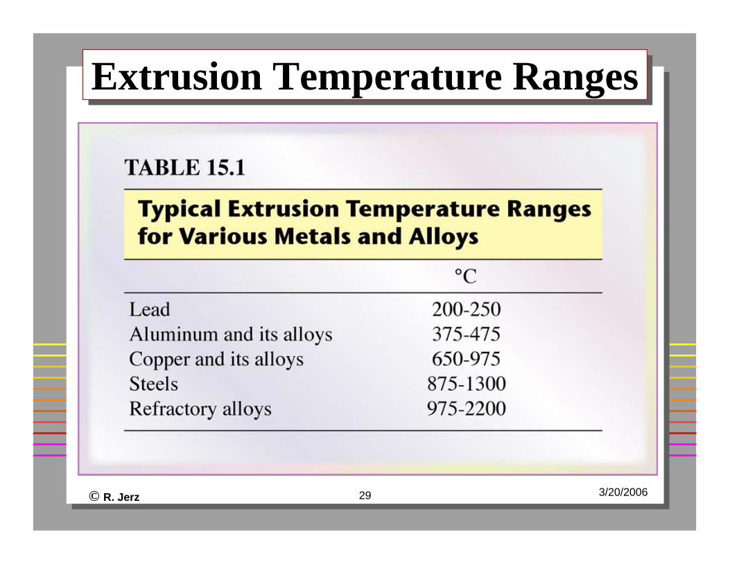
Extrusion Temperature RangesExtrusion Temperature Ranges
© R. Jerz 30 3/20/2006
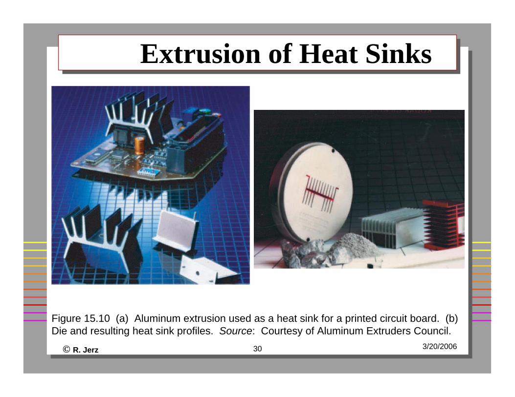
Extrusion of Heat SinksExtrusion of Heat Sinks
Figure 15.10 (a) Aluminum extrusion used as a heat sink for a printed circuit board. (b) Die and resulting heat sink profiles. Source: Courtesy of Aluminum Extruders Council.
© R. Jerz 31 3/20/2006
Cold-Extruded Spark PlugCold-Extruded Spark Plug
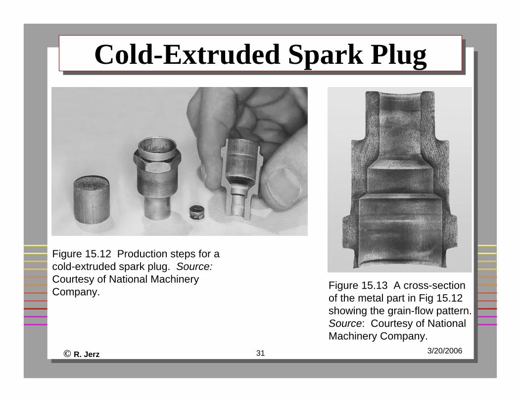
Figure 15.12 Production steps for a cold-extruded spark plug. Source:Courtesy of National Machinery Company. Figure 15.13 A cross-section
of the metal part in Fig 15.12 showing the grain-flow pattern. Source: Courtesy of National Machinery Company.
© R. Jerz 32 3/20/2006
Sheet Metal Processes - Ch16Sheet Metal Processes - Ch16
© R. Jerz 33 3/20/2006
Process OverviewProcess Overview
Make a variety of parts from sheets of metal by cutting and bending them into shapeExamples
© R. Jerz 34 3/20/2006
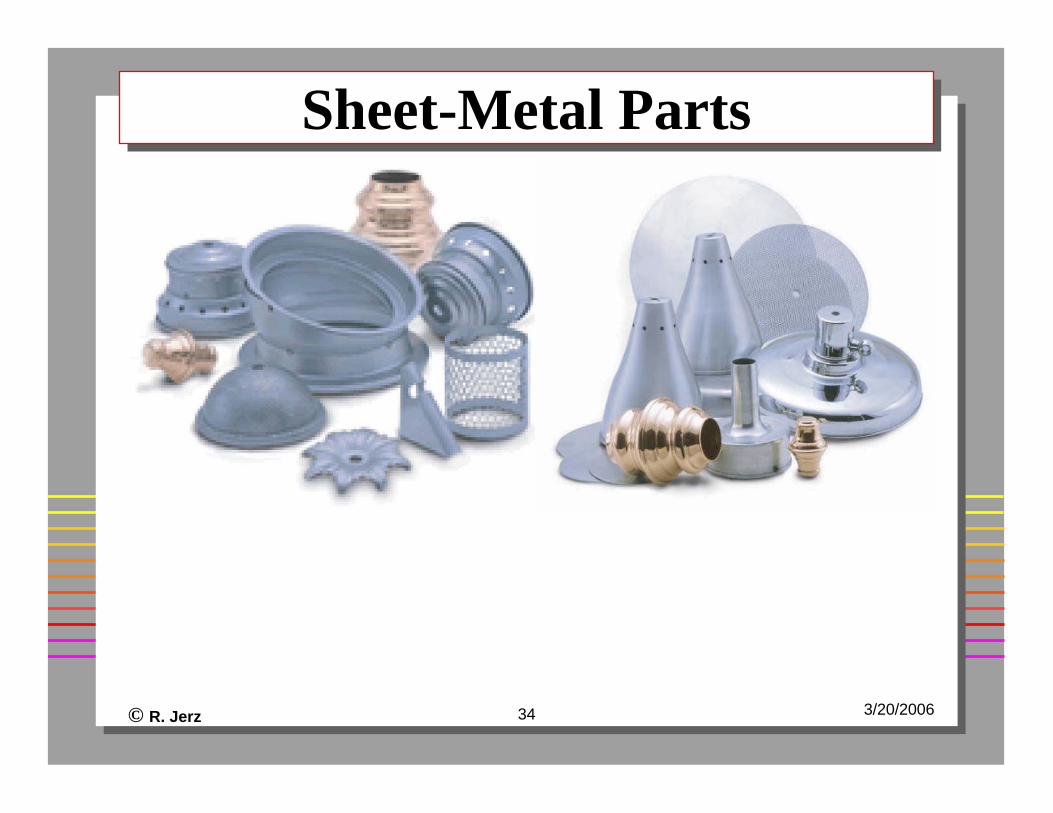
Sheet-Metal PartsSheet-Metal Parts
© R. Jerz 35 3/20/2006
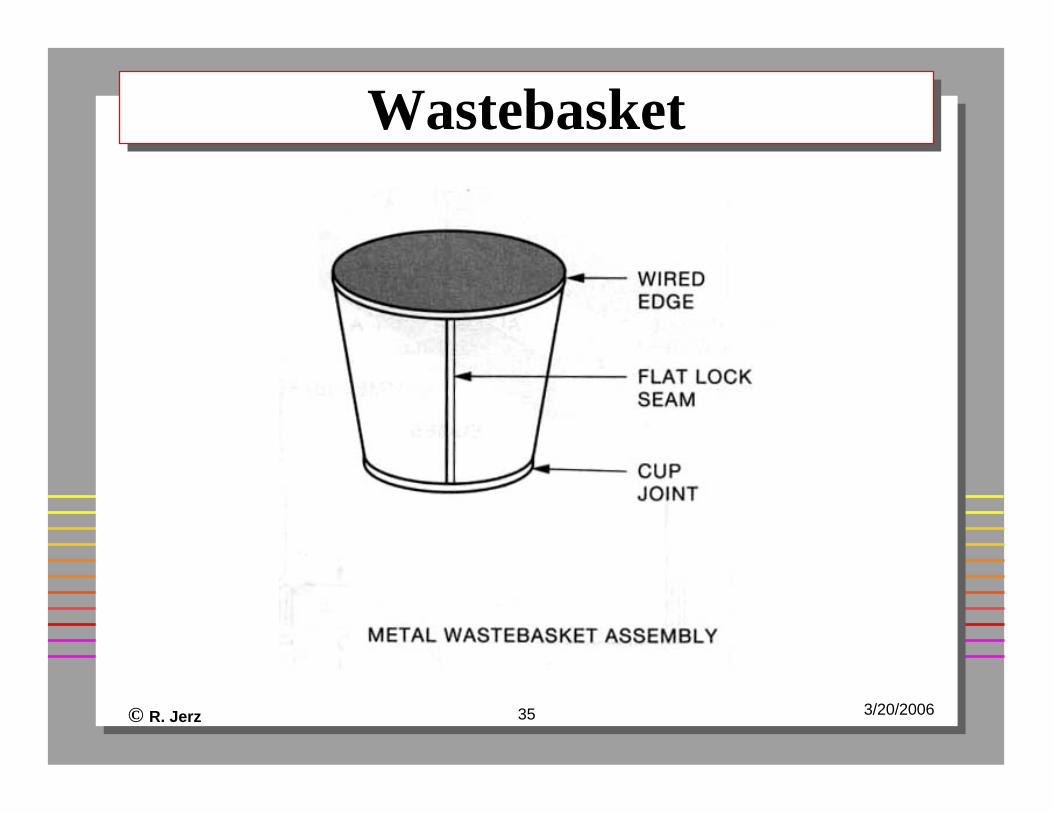
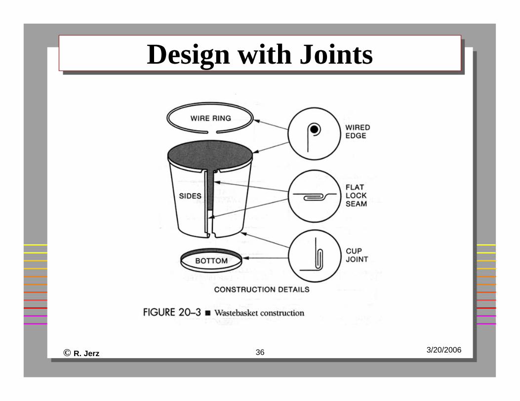
WastebasketWastebasket
© R. Jerz 36 3/20/2006
Design with JointsDesign with Joints
© R. Jerz 37 3/20/2006
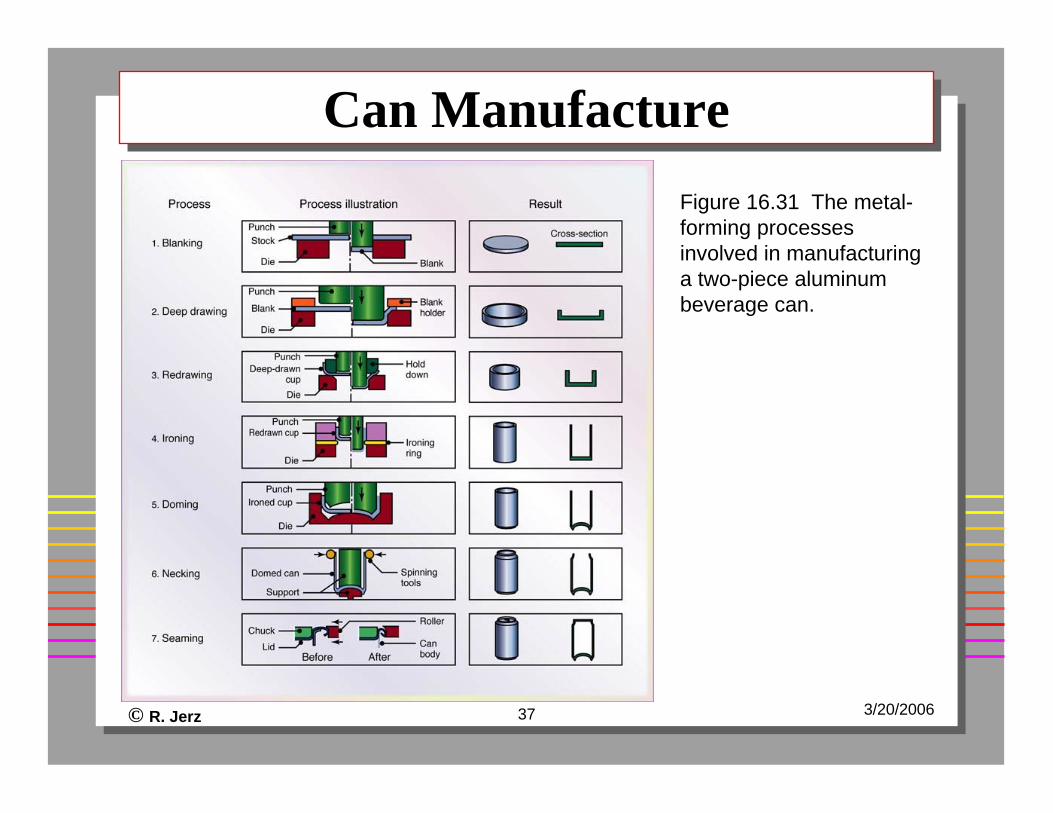
Can ManufactureCan ManufactureFigure 16.31 The metal-forming processes involved in manufacturing a two-piece aluminum beverage can.
© R. Jerz 38 3/20/2006
Forming VideoForming Video
© R. Jerz 39 3/20/2006
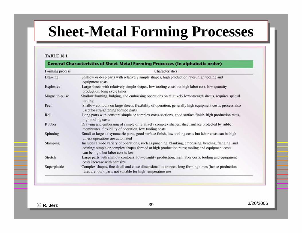
Sheet-Metal Forming ProcessesSheet-Metal Forming Processes
© R. Jerz 40 3/20/2006
Engineering ProblemsEngineering Problems
Shape design and materialsSize of equipment (force)NestingMinimum bend radiusSpringbackBend allowance
© R. Jerz 41 3/20/2006
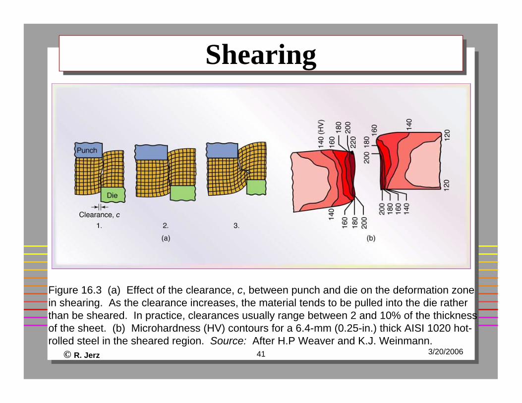
ShearingShearing
Figure 16.3 (a) Effect of the clearance, c, between punch and die on the deformation zone in shearing. As the clearance increases, the material tends to be pulled into the die rather than be sheared. In practice, clearances usually range between 2 and 10% of the thickness of the sheet. (b) Microhardness (HV) contours for a 6.4-mm (0.25-in.) thick AISI 1020 hot-rolled steel in the sheared region. Source: After H.P Weaver and K.J. Weinmann.
© R. Jerz 42 3/20/2006
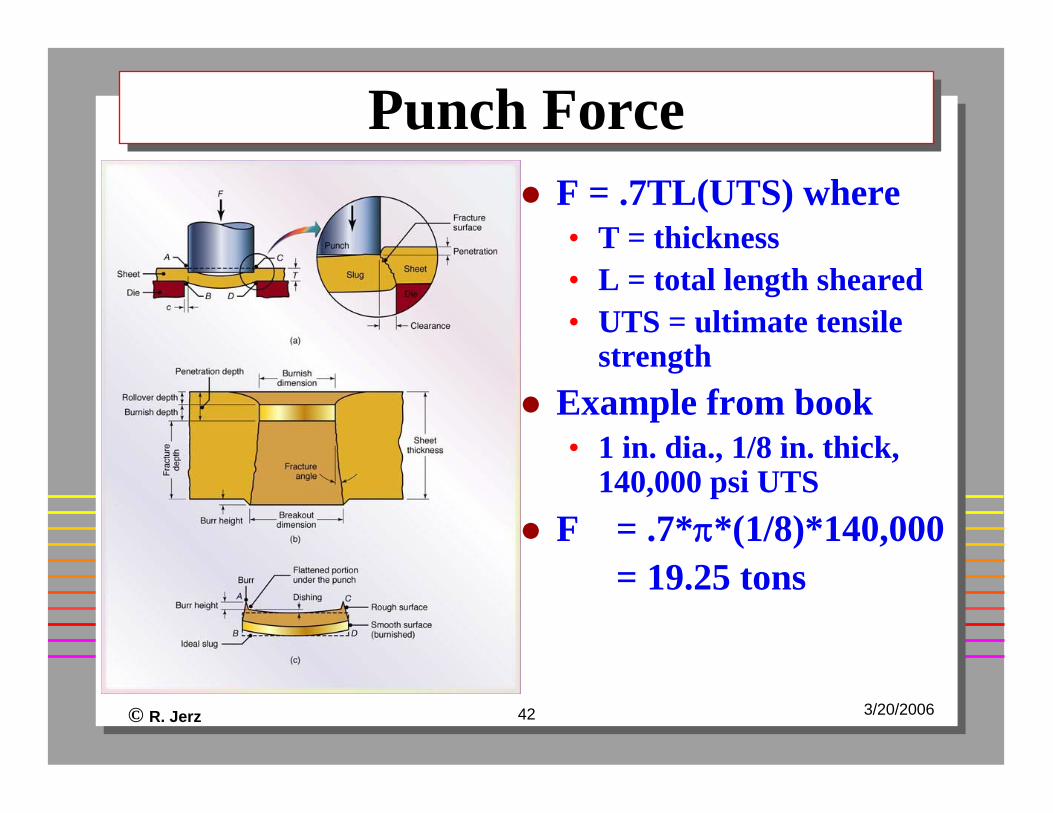
Punch Force Punch Force F = .7TL(UTS) where• T = thickness• L = total length sheared• UTS = ultimate tensile
strengthExample from book• 1 in. dia., 1/8 in. thick,
140,000 psi UTSF = .7*π*(1/8)*140,000
= 19.25 tons
© R. Jerz 43 3/20/2006
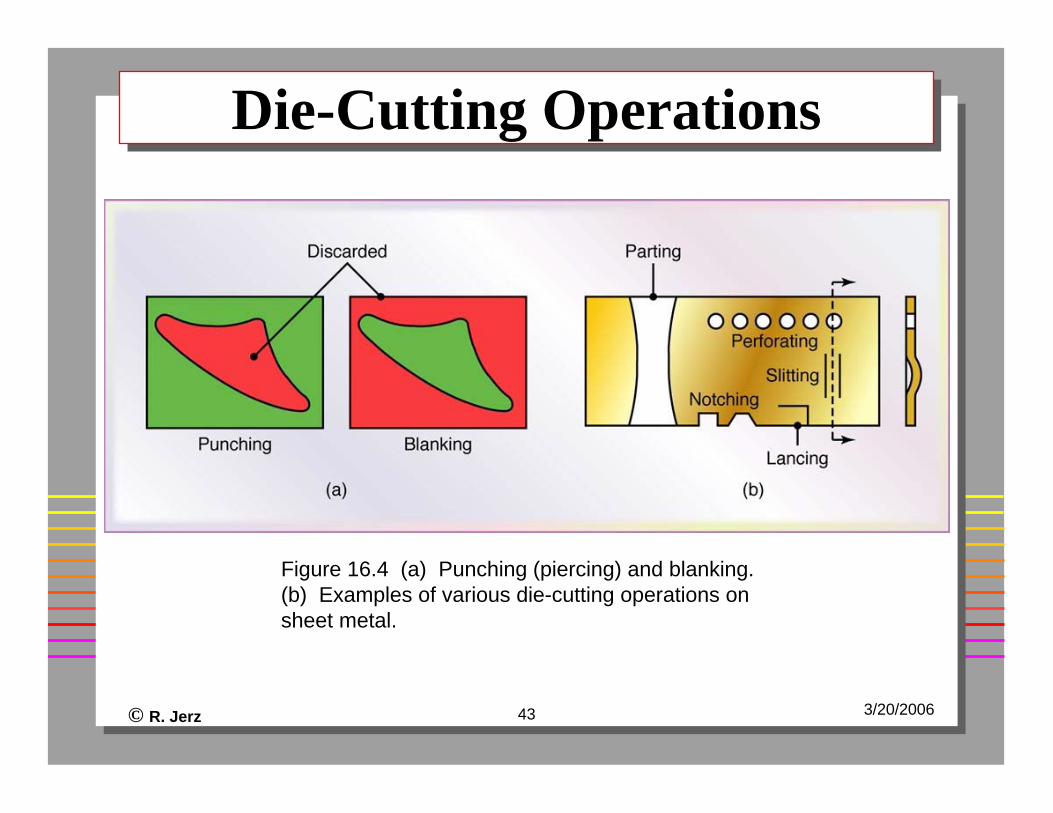
Die-Cutting OperationsDie-Cutting Operations
Figure 16.4 (a) Punching (piercing) and blanking. (b) Examples of various die-cutting operations on sheet metal.
© R. Jerz 44 3/20/2006
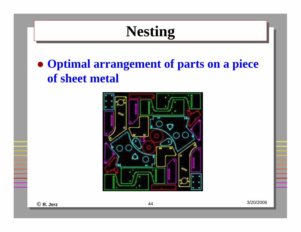
NestingNesting
Optimal arrangement of parts on a piece of sheet metal
© R. Jerz 45 3/20/2006
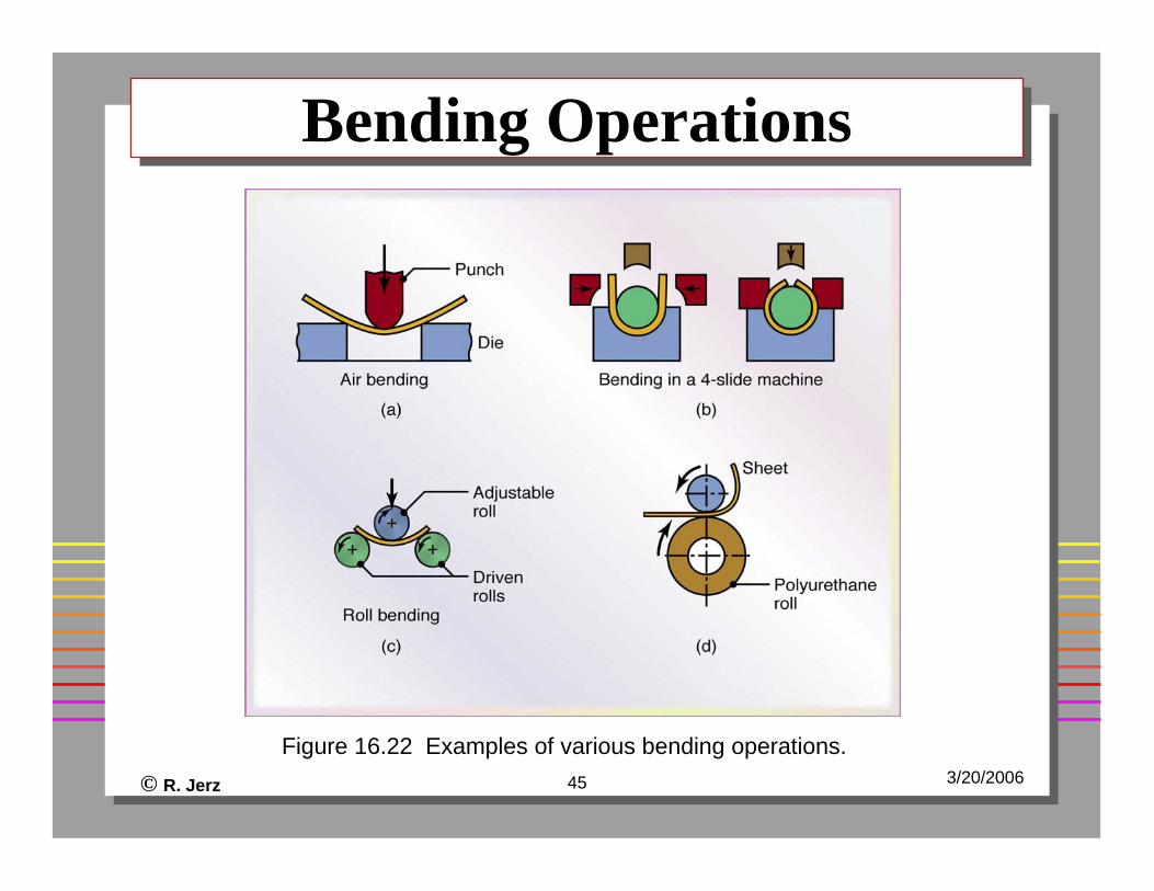
Bending OperationsBending Operations
Figure 16.22 Examples of various bending operations.
© R. Jerz 46 3/20/2006
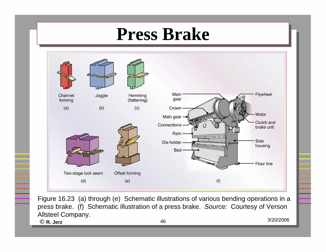
Press BrakePress Brake
Figure 16.23 (a) through (e) Schematic illustrations of various bending operations in a press brake. (f) Schematic illustration of a press brake. Source: Courtesy of VersonAllsteel Company.
© R. Jerz 47 3/20/2006
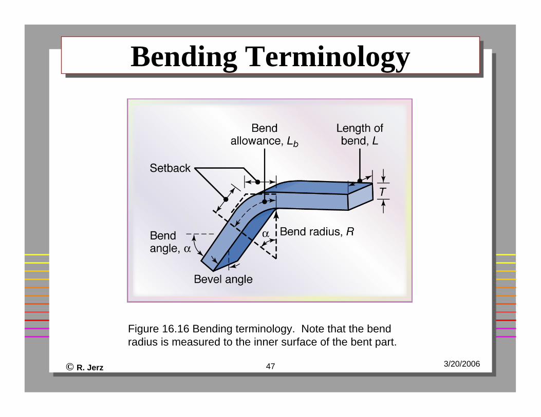
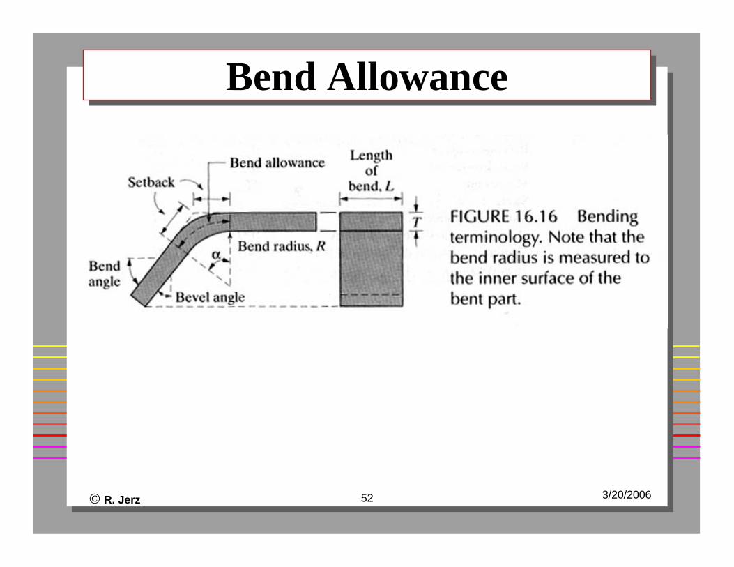
Bending TerminologyBending Terminology
Figure 16.16 Bending terminology. Note that the bend radius is measured to the inner surface of the bent part.
© R. Jerz 48 3/20/2006
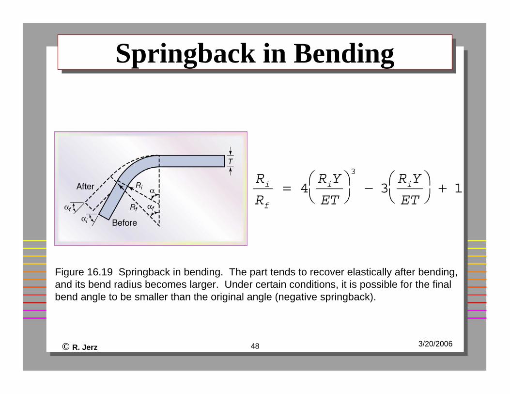
Springback in BendingSpringback in Bending
Figure 16.19 Springback in bending. The part tends to recover elastically after bending, and its bend radius becomes larger. Under certain conditions, it is possible for the final bend angle to be smaller than the original angle (negative springback).
Ri
Rf
= 4RiY
ET⎛ ⎝
⎞ ⎠
3
− 3RiY
ET⎛ ⎝
⎞ ⎠
+ 1
© R. Jerz 49 3/20/2006
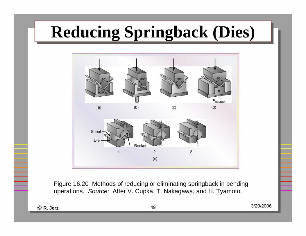
Reducing Springback (Dies)Reducing Springback (Dies)
Figure 16.20 Methods of reducing or eliminating springback in bending operations. Source: After V. Cupka, T. Nakagawa, and H. Tyamoto.
© R. Jerz 50 3/20/2006
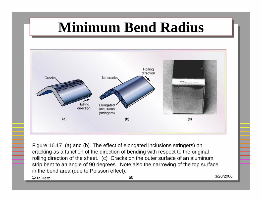
Minimum Bend RadiusMinimum Bend Radius
Figure 16.17 (a) and (b) The effect of elongated inclusions stringers) on cracking as a function of the direction of bending with respect to the original rolling direction of the sheet. (c) Cracks on the outer surface of an aluminum strip bent to an angle of 90 degrees. Note also the narrowing of the top surface in the bend area (due to Poisson effect).
© R. Jerz 51 3/20/2006
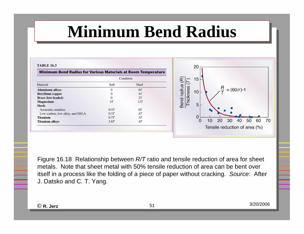
Minimum Bend RadiusMinimum Bend Radius
Figure 16.18 Relationship between R/T ratio and tensile reduction of area for sheet metals. Note that sheet metal with 50% tensile reduction of area can be bent over itself in a process like the folding of a piece of paper without cracking. Source: After J. Datsko and C. T. Yang.
© R. Jerz 52 3/20/2006
Bend AllowanceBend Allowance
© R. Jerz 53 3/20/2006
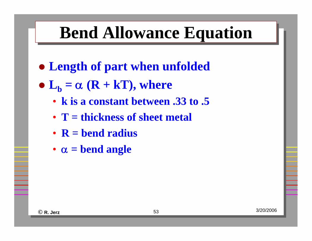
Bend Allowance EquationBend Allowance Equation
Length of part when unfoldedLb = α (R + kT), where• k is a constant between .33 to .5• T = thickness of sheet metal• R = bend radius• α = bend angle

© R. Jerz 54 3/20/2006
Understanding Bend AllowanceUnderstanding Bend Allowance
(Instructor Notes)
© R. Jerz 55 3/20/2006
CAD DemoCAD Demo