Formation Sensitivity Assessment of the Gbaran Field ...
12
International journal of scientific and technical research in engineering (IJSTRE) www.ijstre.com Volume 2 Issue 9 ǁ September 2017. Manuscript id. 752206943 www.ijstre.com Page 1 Formation Sensitivity Assessment of the Gbaran Field, Niger Delta Basin, Nigeria Bertram Maduka Ozumba, PhD Federal University, Ndufu-Amaikwo, PMB 1010, Abakaliki, Nigeria Abstract : The prolific Niger Delta Basin is a mature petroleum province. Therefore, further prospectivity in the basin lies within deeper plays which are high pressure and high temperature (HPHT) targets. One of the main characteristics of the Niger Delta is its unique diachronous tripartite stratigraphy. Its gross onshore and shallow offshore lithostratigraphy consists of the deep-seated Akata Formation and is virtually exclusively shale, the petroliferous paralic Agbada Formation in which sand/shale proportion systematically increases upward, and at the top the Benin Formation composed almost exclusively of sand. This stratigraphic pattern is not exactly replicated in the deep offshore part of the delta. The downward increasing shale percentage in the older and deeper parts of the basin poses a great problem to drilling. Increasing shaliness usually leads to wellbore instability and such other problems as pack-offs and stuck pipe. These hazards are the main causes of non-productive time in expensive deep-water or high temperature and high pressure (HPHT) drilling operations. Moreover clay mineral diagenesis generates mixed layer clays at higher temperatures and this tends to cause overpressures that may lead to disastrous kicks, losses, and even blowouts. Predicting and managing drilling in such overpressured or problem sections will form a major part of the evaluation for exploration and development in these parts of the delta. A formation sensitivity test consisting of the detailed study of the influence of various ions on the degree of formation damage of one of the main producing fields in the eastern Niger Delta has been undertaken. Analytical results of clay mineral composition obtained using X-ray diffraction (XRD) methodology were successfully applied to predict the various types of clay minerals present and hence intervals of problem shales. Further experimental formulations derived using Capillary Suction Time (CST) tests found that addition of 7% KCl to the original water based drilling fluid made drilling through the problem sequences easier, and this led to very substantial cost savings and compliance with the Nigerian environmental regulations. The operator has planned deeper drilling and further development of the field. I. INTRODUCTION 1.1. FIELD GEOLOGICAL SETTING AND STRUCTURE The Gbaran field is a large, partially developed field situated in OML 28 (Fig. 1a, 1b) in the seasonally fresh- water swamp area, some 110 Km west of Port Harcourt, Rivers State, Nigeria. The field was discovered with the drilling of Gbaran-001 well in 1967. Many wells (> 27) have been used to appraise and develop the field. Currently the field is producing both oil and gas. The gas is used as a feed stock to one of the Nigerian Liquefied Natural Gas (NLNG ) trains in Bonny. In the last few years efforts have targeted two deeper objectives with the aim to generate more gas to for the NLNG plantThe Gbaran structure shows dual culmination roll-over anticline believed to have formed in response to the growth of the main boundary faults as the sediments were being deposited (Fig. 2). It is part of the Zarama, Ubie, Etelebou and Kolo Creek north-south macrostructure within the Niger Delta Ughelli megastructure. To the east of these fields are macrostructures characterised by thin paralic sequences which lack hydrocarbon charge while to the west are low relief, gas-bearing rollover structures (Abasare, Koroama, Epu fields). The stratigraphic sequence is of Lower Miocene (Burdigalian) age and within the P670 - P680 palynological zonation of Evamy et al. (1978). II. NIGER DELTA REGIONAL GEOLOGICAL SETTING The Niger Delta Basin is an extensional rift system located in the central part of the Nigerian coastal stretch. It has been, and is still being, built out on the passive continental margin into the Gulf of Guinea. It is one of the largest basins in Africa, with a subaerial extent of about 75,000 km 2 , a total area of 300,000 km 2 , and a sediment fill of ca. 500,000 km 3 [1]. The sediment fill has a thickness between 9 – 12 km (Burke, 1972; Whiteman, 1982). It is surrounded by other basins that all formed from similar processes and lies atop the
Transcript of Formation Sensitivity Assessment of the Gbaran Field ...

International journal of scientific and technical research in engineering (IJSTRE)
www.ijstre.com Volume 2 Issue 9 ǁ September 2017.
Manuscript id. 752206943 www.ijstre.com Page 1
Formation Sensitivity Assessment of the Gbaran Field, Niger
Delta Basin, Nigeria
Bertram Maduka Ozumba, PhD
Federal University, Ndufu-Amaikwo, PMB 1010, Abakaliki, Nigeria
Abstract : The prolific Niger Delta Basin is a mature petroleum province. Therefore, further prospectivity in
the basin lies within deeper plays which are high pressure and high temperature (HPHT) targets. One of the
main characteristics of the Niger Delta is its unique diachronous tripartite stratigraphy. Its gross onshore and
shallow offshore lithostratigraphy consists of the deep-seated Akata Formation and is virtually exclusively
shale, the petroliferous paralic Agbada Formation in which sand/shale proportion systematically increases
upward, and at the top the Benin Formation composed almost exclusively of sand. This stratigraphic pattern is
not exactly replicated in the deep offshore part of the delta.
The downward increasing shale percentage in the older and deeper parts of the basin poses a great problem to drilling. Increasing shaliness usually leads to wellbore instability and such other problems as pack-offs and
stuck pipe. These hazards are the main causes of non-productive time in expensive deep-water or high
temperature and high pressure (HPHT) drilling operations. Moreover clay mineral diagenesis generates mixed
layer clays at higher temperatures and this tends to cause overpressures that may lead to disastrous kicks,
losses, and even blowouts. Predicting and managing drilling in such overpressured or problem sections will
form a major part of the evaluation for exploration and development in these parts of the delta.
A formation sensitivity test consisting of the detailed study of the influence of various ions on the degree of
formation damage of one of the main producing fields in the eastern Niger Delta has been undertaken.
Analytical results of clay mineral composition obtained using X-ray diffraction (XRD) methodology were
successfully applied to predict the various types of clay minerals present and hence intervals of problem shales.
Further experimental formulations derived using Capillary Suction Time (CST) tests found that addition of 7%
KCl to the original water based drilling fluid made drilling through the problem sequences easier, and this led to very substantial cost savings and compliance with the Nigerian environmental regulations. The operator has
planned deeper drilling and further development of the field.
I. INTRODUCTION
1.1. FIELD GEOLOGICAL SETTING AND STRUCTURE
The Gbaran field is a large, partially developed field situated in OML 28 (Fig. 1a, 1b) in the seasonally fresh-
water swamp area, some 110 Km west of Port Harcourt, Rivers State, Nigeria. The field was discovered with the
drilling of Gbaran-001 well in 1967. Many wells (> 27) have been used to appraise and develop the field.
Currently the field is producing both oil and gas. The gas is used as a feed stock to one of the Nigerian Liquefied
Natural Gas (NLNG ) trains in Bonny. In the last few years efforts have targeted two deeper objectives with the
aim to generate more gas to for the NLNG plantThe Gbaran structure shows dual culmination roll-over anticline
believed to have formed in response to the growth of the main boundary faults as the sediments were being deposited (Fig. 2). It is part of the Zarama, Ubie, Etelebou and Kolo Creek north-south macrostructure within
the Niger Delta Ughelli megastructure. To the east of these fields are macrostructures characterised by thin
paralic sequences which lack hydrocarbon charge while to the west are low relief, gas-bearing rollover
structures (Abasare, Koroama, Epu fields). The stratigraphic sequence is of Lower Miocene (Burdigalian) age
and within the P670 - P680 palynological zonation of Evamy et al. (1978).
II. NIGER DELTA REGIONAL GEOLOGICAL SETTING
The Niger Delta Basin is an extensional rift system located in the central part of the Nigerian coastal
stretch. It has been, and is still being, built out on the passive continental margin into the Gulf of Guinea. It is
one of the largest basins in Africa, with a subaerial extent of about 75,000 km2, a total area of 300,000 km2, and
a sediment fill of ca. 500,000 km3 [1]. The sediment fill has a thickness between 9 – 12 km (Burke, 1972;
Whiteman, 1982). It is surrounded by other basins that all formed from similar processes and lies atop the

Formation Sensitivity Assessment of the Gbaran Field, Niger Delta Basin, Nigeria
Manuscript id. 752206943 www.ijstre.com Page 2
Benue Trough a much larger tectonic structure. The eastern bound of the basin is marked by the Cameroon
Volcanic Line and the transform passive continental margin [2]. The delta exhibits a large arcuate shape typical
of the destructive wave-dominated type on the western side, and a tide-dominated shape on the eastern side
while the central part is river-dominated. The delta sediments show an overall transition from marine prodelta
shales (Akata Formation) through a paralic interval (Agbada Formation) and a continental succession (Benin
Formation) (Short and Stauble, 1967). It is the most significant hydrocarbon province on the western African
continental margin. It started to evolve in the Eocene epoch t and deposition is still on-going offshore. Over 150
oil fields have been developed in it with the offshore blocks making approximately one fifth of this number
(Figure 3).
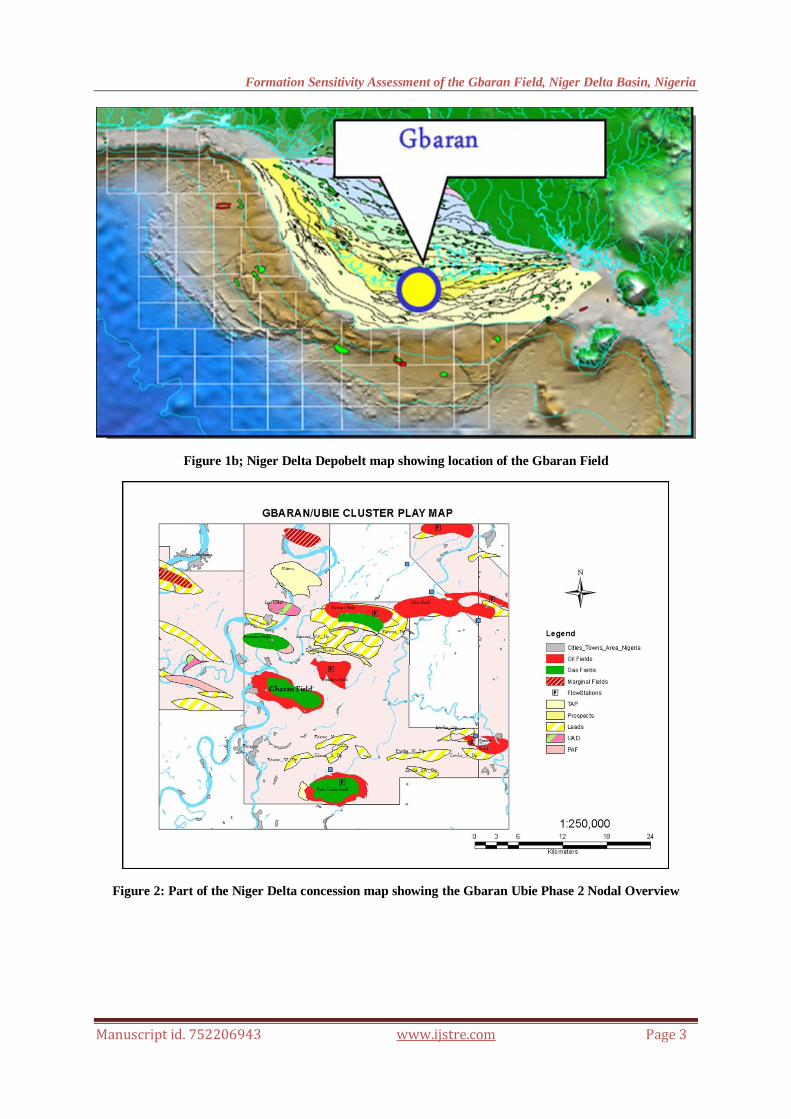
Shale diapirism due to compression makes this basin different. The main impetus for deformation is
however the gravitational collapse of the basin. The most striking deformational structural features are the large
syn-sedimentary growth faults, rollover anticlines and shale diapirs (Evamy et al., 1978). The basin is divided
into three zones based on its tectonic structure: an extensional zone lying on the continental shelf, over a
thickened crust, transition zone, and a contraction zone, which lies in the deep sea part of the basin.
The escalator regression model of Knox and Omatsola (1989) describes the one-way stepwise
outbuilding of the Niger Delta through geologic time. The units of these steps are the depobelts which represent
successive phases of delta growth (Doust and Omatsola, 1990). They are composed of bands of sediments about
30-60 km wide with lengths or up to 300 km. They contain major fault-bounded successions which contain a
shoreface alternating sand/shale sequence limited at the proximal end by a major boundary growth fault of a
succeeding depobelt, or any combination of these. Seawards, successive depobelts contain sedimentary fills
markedly younger than the adjacent ones in the landward direction.
The five major depobelts generally recognized as shown in Figure 3 are Northern Delta, Greater
Ughelli, Central Swamp, Coastal Swamp, Shallow and Deep Offshore. The Deep Offshore has a unique
structural style (Armentrout et al., 2000; Hooper et al., 2002).
Figure 1a: The Niger Delta Basin located in the Gulf of Guinea on the west coast of Africa.
Formation Sensitivity Assessment of the Gbaran Field, Niger Delta Basin, Nigeria
Manuscript id. 752206943 www.ijstre.com Page 3
Figure 1b; Niger Delta Depobelt map showing location of the Gbaran Field
Figure 2: Part of the Niger Delta concession map showing the Gbaran Ubie Phase 2 Nodal Overview
Formation Sensitivity Assessment of the Gbaran Field, Niger Delta Basin, Nigeria
Manuscript id. 752206943 www.ijstre.com Page 4
Figure 3: The Niger Delta regional structural and stratigraphic elements (after Corredor et al., 2005)
III. Gbaran Field Drilling Challenge
Up until the end of 2014, 26 wells had been drilled in the Gbaran field (Fig. 4). Five of the earliest wells were drilled entirely with Water-Based Muds (WBM) while some intervals in 20 wells were drilled with
Oil-Based Muds (OBM) (Figure 5). Following regulations by the Nigerian Department of Petroleum Resources
(DPR), the use of OBM was severely limited as a result of its perceived effect on the environment. This was
playing out as the Gbaran Field (Figure 6) was seen as holding a lot of undrilled and undeveloped potentials for
SPDC and the country at large. The partial drilling of 20 wells with oil-based muds became necessary due to
challenges posed by stuck pipes in those intervals and the subsequent loss of drilling time and money in freeing
the pipes (Figure 5).

Formation Sensitivity Assessment of the Gbaran Field, Niger Delta Basin, Nigeria
Manuscript id. 752206943 www.ijstre.com Page 5
Figure 4: Structure map of Gbaran Field at the sand below 17.4 Ma MFS level
Figure 5: Locations of the wells Gbaran Field and the colours depicting the type of drilling mud used

Formation Sensitivity Assessment of the Gbaran Field, Niger Delta Basin, Nigeria
Manuscript id. 752206943 www.ijstre.com Page 6
Figure 6: Stratigraphic framework with sample points at important stratigraphic levels. Inserts are the
line of section and the time frame for the deposition of the Gbaran structure using the Niger Delta
Chronostratigraphic Scheme.
Economically the SPDC was losing money per well as a result of the drilling challenges and the company was
also not meeting important milestones in the overall company business plan thereby losing even more money.
More importantly, the Company was losing its reputation in terms of timely delivery of projects. A high level decision was made to only drill the next set of wells using WBM. To do that, a study was instituted to:
Investigate the clay mineral distribution in the field and predict the spatial and temporal distribution of
swelling clays (mixed layer illite/smectite),
Understand the clay composition within the field with a view to selecting an optimal and economic
drilling mud for drilling deeper intervals in the field,
Verify that a new, environmentally friendly and more cost-effective WBM (Water-Based Mud) system
with 7% potassium chloride (KCl) would sufficiently sustain borehole stability,
Deliver predictive occurrences of troublesome intervals across Gbaran field (illite/smectite & hard
streaks/calcite-cemented intervals) with a view to faster drilling and saving cost.
IV. Clay Mineral
Clay mineralogy controls to a large extent the mechanical, electrical, thermal and acoustic properties of
the source, reservoir & seal rocks. It also influences reservoir properties, trap integrity, seismic response,
fracture properties and borehole stability. These are all important variables in hydrocarbon exploration,
development and production.

Formation Sensitivity Assessment of the Gbaran Field, Niger Delta Basin, Nigeria
Manuscript id. 752206943 www.ijstre.com Page 7
3.1: Definitions of Clay and Clay Mineral
Encyclopaedia Britannica defines the term „clay‟ as the finest division of many particle size schemes; or a term
applied to many naturally occurring materials that may otherwise be classified as soil, sediment or rock. Not
surprisingly then, there is no universally accepted definition of the word “clay”, although in context its meaning is generally understood. Guggenheim and Martin (1995) offered the definition of clay as a material: “.......a
naturally occurring material composed primarily of fine-grained minerals, which is generally plastic at
appropriate water contents and will harden when dried or fired. Although clay usually contains phyllosilicates, it
may contain other materials that impart plasticity and harden when dried or fired”.
However, clay mineralogy is the scientific discipline concerned with all aspects of clay minerals, including their
properties, composition, classification, crystal structure, and occurrence and distribution in nature. The methods
of study include X-ray diffraction, infrared spectroscopic analysis, chemical analyses of bulk and
monomineralic samples, determinations of cationic exchange capacities, electron-optical studies, thermal studies by differential thermal analysis, and thermo-gravimetric methods.
3.2: Clay Mineral Classification
The classification of the phyllosilicate clay minerals is based collectively on the features of layer type (Table 1),
the dioctahedral or trioctahedral character of the octahedral sheets, and the nature of the interlayer material. Tables 1, 2, and 3 show the different methods that have been used in this study.
Table 1: Clay Mineral Classification used in this study (O’Brien and Chenevert, 1973)
Class Characteristics Clay Mineral
1 Soft, highly dispersive (Gumbo), mud-making High smectite some illite
2 Soft, fairly dispersive, mud- making High illite, fairly high smectite
3 Medium hard, moderately dispersive,
Sloughing
High in illite, chlorite
4 Hard, little dispersion, Sloughing Moderate illite, moderate chlorite
5 Very hard, brittle, no dispersion ,caving High illite, moderate chlorite
Table 2: Clay minerals percent in Problem Shales (O’Brien and Chenevert, 1973)
Clays Shales H2O (%)
RH 50%
Mont. Illite ML chlorite
Anahuac 1 >4.0 40.0 5.5 - -
Vermillion 2 - 25.4 42.0 - 6.7
Atoka 3 - - 38.8 18.21 13.0
Midway 3 2.4 – 2.8 - 35.0 15.0 15.0
Wolf camp 4 1.5 – 2.0 - 14.8 3.2
Canadian
Hard
5 0.4 – 1.0 - 48.3 - 8.3
Anahuac 1 >4.0 40.0 5.5 - -

Formation Sensitivity Assessment of the Gbaran Field, Niger Delta Basin, Nigeria
Manuscript id. 752206943 www.ijstre.com Page 8
Table 3: Swelling and dispersion behavior of class 2 shale in various fluids (after O’Brien and Chenevert, 1973)
Solution % Linear Swelling Appearance % Shale Recovery
Water - Total disintegration 1.3
10% CaCl2 2.18 Partial disintegration 5.0
10% NaCl 2.00 Intact, easily crumbled 8.8
10% KCl 1.49 Intact, firm 46.0
10% KCl + Polymer 0.00 Intact, firm 91.6
3.3: Clay Mineral Analysis
It has been well established that some clay minerals, such as mixed-layered clay, can only be identified precisely
by techniques such as XRD. Other techniques such as infrared spectroscopy, and electron microscopy are used
to characterise and more fully understand the types of clay minerals present in a sample.
In this study XRD was recommended. XRD analysis is used to identify crystalline compounds (minerals) based
on their crystal structure. Each compound gives a unique pattern of diffraction peaks. A pattern from an
unknown sample can be compared to standard patterns for qualitative and quantitative identification.
3.4 Clay Mineral Results
The results of the XRD analysis are shown in Table 4 and Figures 7, 8 and 9.
Figure 7: Stratigraphic framework and mineralogy showing the correlation of the different shale types
after analysis

Formation Sensitivity Assessment of the Gbaran Field, Niger Delta Basin, Nigeria
Manuscript id. 752206943 www.ijstre.com Page 9
Table 4: Results of XRD analysis
Clays
Clays account for, on average by weight, 47% of the sample quantity. The clay types
detected include chlorite (1% - 12%; average 5%), kaolinite (5% - 49%; average
33%), illite/mica (trace - 16%; average 3%), and mixed-layer illite/smectite (trace -
12%; average 6%). The most common clay type detected is kaolinite. Mixed-layer
illite/smectite is composed of ordered interstratified clay with 35% - 55% expandable layers. Clay volume tends to decrease in samples with increased carbonate and/or
quartz.
Carbonates
Carbonates detected include calcite (trace - 25%; average 4%), dolomite (0% - 2%;
average trace), and siderite (trace - 31%; average 3%). Calcite is especially common
at Gbaran-17 (@ 12330‟), accounting for 25% of this sample volume. Siderite is also
common at Gbaran-01 well (@ 8493‟), accounting for 31% of this sample volume. In
most samples, however, carbonate volume is fairly low (<10% in 31 of 38 samples).
Quartz
Quartz is the other dominant mineral in this sample suite and is quite variable in
volume, ranging from 14% - 87% by weight. Nine samples contain show quartz
content higher than 50%. Visual examination of these cuttings shows an abundance
of loose sand. Visual examination suggests that most grains are likely monocrystalline
and fine to very fine-grained. The feldspar content in these samples is fairly low,
ranging from 3% - 15%. Pyrite, gypsum, jarosite, halite and sylvite were detected in
trace amounts.
Figure 8: XRD clay mineral analysis results
Figure 9: XRD carbonate analysis results
Formation Sensitivity Assessment of the Gbaran Field, Niger Delta Basin, Nigeria
Manuscript id. 752206943 www.ijstre.com Page 10
V. Capillary Suction Time (CST)
CST measures the tendency a rock has to hold onto fluid. In filter-cake evaluations, CST measures
reactivity of water-based drilling muds (WBM) or completion fluids. This test may also be used to study how clays and shale react in filter cakes; it can also be a quick look for rock/fluid sensitivity.
In attempts to overcome problem shales several classification schemes have been developed utilizing X-Ray
diffraction (Kevin Hart, 1989). This approach involves classifying the shale according to primary clay content
such as montmorillonite, kaolinite etc. However, x-ray diffraction does not reveal surface properties of the clay.
Over the years, there have been many attempts to overcome difficulties encountered in drilling shale zones.
Several researchers have designed both water- and oil-based drilling fluids to increase wellbore stability.
Although some success was achieved using oil-based muds, costs and environmental factors make it necessary
to design a water-based mud to control shale instability. This was achieved by O'Brien and Chenevert (1973)
who demonstrated the effectiveness of using potassium chloride as a shale inhibitor. Steiger (1982) advocated
the use of potassium/polymer drilling fluids for shale inhibition. These mud systems had the added feature of
being less expensive and easier to use than oil-based muds.
Wilcox and Fiskin (1983) were the first to use the Capillary Suction Time (CST) test and ensilin data to aid in
predicting the behaviour of the shale zone being drilled. The CST test is simple and can be carried out at the rig
site using these two tests.
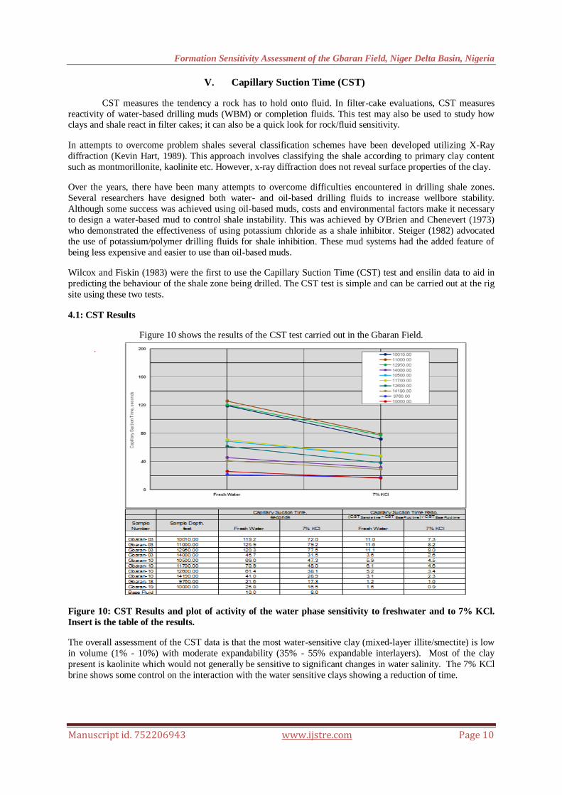
4.1: CST Results
Figure 10 shows the results of the CST test carried out in the Gbaran Field.
Figure 10: CST Results and plot of activity of the water phase sensitivity to freshwater and to 7% KCl.
Insert is the table of the results.
The overall assessment of the CST data is that the most water-sensitive clay (mixed-layer illite/smectite) is low
in volume (1% - 10%) with moderate expandability (35% - 55% expandable interlayers). Most of the clay
present is kaolinite which would not generally be sensitive to significant changes in water salinity. The 7% KCl
brine shows some control on the interaction with the water sensitive clays showing a reduction of time.
Formation Sensitivity Assessment of the Gbaran Field, Niger Delta Basin, Nigeria
Manuscript id. 752206943 www.ijstre.com Page 11
VI. Conclusions
Examination of the XRD and CST data indicatesas follows:
These shales/sands of the Gbaran field are sensitive to fresh water and the use of 7% KCl additive (to drilling
mud) reduces the clay/fluid interaction hence should be used whenever swelling clays are encountered.
Kaolinite is the most abundant, but water-sensitive clay, mixed-layer smectite/illite, though fairly low in volume
(trace - 12%), is expandable (35% - 55% expandable layers).
Susceptible intervals to watch in the field have been depicted in the correlation diagram and the prediction of
probable depths of occurrence before drilling can be integrated in the well engineering plan.
Successful application has potential for significant savings in both rig downtime and cost of oil based muds.
Good environmental management and stakeholder relationship are also achieved.
VII. Recommendations
If drilling issues persist with the use of 7% KCl fluid or oil-based fluids, other factors such should be
considered as possible reasons:
Use of additives that will prevent clay dispersion and/or minimize clay-water interaction could help to evacuate
cuttings more efficiently and faster.
Drill bit type – The mineralogy of the samples are quartz/clay-rich with occasional carbonate present. It is
likely that the hardness of the rock will be variable between friable shale sand and possible carbonate-cemented
rock. A drill bit should be chosen to accommodate potentially hard/soft sediments.
Study should be replicated in other fields where further development is planned.
References
[1.] Armentrout, J.M., Kanschat, K.A., Meisling, K., Tsakma, J.J., Antrim, L., and McConnell, D.R., 2000.
[2.] Burke, K., 1972. Longshore drift, submarine canyons and submarine fans in development of Niger
[3.] Chenevert, M.E.: "Shale Control with Balanced- Activity Oil-Continuous Muds", Journal of Petroleum Technology, (Oct. 1970) 1309-1316.
[4.] Corredor, F., Shaw, J.H., and Billeti, F.,2005. Structural styles in deep water fold and thrust belts of the
Niger Delta. AAPG Bulletin, vol 89, p.753 - 780
[5.] Doust, H., and E. Omatsola, 1990. Niger Delta, in J. D. Edwards and P. A. Santogrossi, eds.,Divergent/passive margin basins: AAPG Memoir (48), p. 239-248.
[6.] Evamy, B.D., Haremboure, J., Kammerling, R., Knaap, W.A., Molloy, F.A., and Rowlands, P.H.,
1978. Hydrocarbon habitat of Tertiary Niger Delta, AAPG, Bulletin, vol. 62, p. 1-39.
[7.] Guggenheim, S., and R. T. Martin (1995) Summary of recommendations of AIPEA Nomenclature
Committee. Clays and Clay Minerals, Vol. 43, No. 2, 255-256, 1995.
[8.] Hooper, R.J., Fitzsimmons, R.J., Grant, N., and Vendeville, B.C., 2002. The role of deformation on
controlling depositional patterns in the south-central Niger Delta, West Africa: Journal of Structural
Geology, vol. 24, p. 847-859.
[9.] Kevin Micheal Hart, 1989. Capillary Suction Time tests on selected clays and shales, Unpublished
Master of Engineering degree thesis, University of Texas at Austin, May 1985.

Formation Sensitivity Assessment of the Gbaran Field, Niger Delta Basin, Nigeria
Manuscript id. 752206943 www.ijstre.com Page 12
[10.] Knox, G. J., and E. Omatsola, 1989.Development of the Cenozoic Niger Delta in terms of „„escalator
regression‟‟ model and impact on hydrocarbon distribution, In: Proceedings, Koninklijk Nederlands
Geologisch Mijnbouw Kundig Genootschap Symposium„ Coastal Lowlands Geology and
Geotechnology,‟‟ 1987: Dordrecht, Kluwer, p. 181-202.
[11.] O'Brien, D.E. and Chenevert, M.E.: "Stabilizing Sensitive Shales with Inhibited Potassium-Based Drilling Fluids", Journal of Petroleum Technology, (Sep 1973) 1089-1100.
[12.] Short, K. C., and Stauble, A. J. 1967, Outline of geology of Niger Delta: AAPG Bulletin, v. 51, pp.
761–779.
[13.] Steiger, R.P., 1982. Fundamentals and Use of Potassium/Polymer Drilling Fluids to Minimize Drilling and Completion Problems Associated with Hydratable Clays. Journal of Petroleum Technology (Aug
1982) 1161 - 1670.
[14.] Wilcox, R. and Fisk, J., 1983. Tests Show Behaviour Aid Well Planning. Oil and Gas Journal, (Sep 12,
1983) 106 – 125.
[15.] Whiteman, A.J., 1982. Nigeria: Its Petroleum Geology Resources and Potential. Parts I and II, London,
Graham and Trotman, p.39.
ACKNOWLEGEMENT
The author is very grateful to Shell Petroleum Development Company of Nigeria (SPDC) Ltd for allowing the
publication of this article, and to Mosunmolu Ltd and WeatherFord Laboratories Houston, USA, for the
technical content especially on the XRD and CST analyses and results. All team members of the Geological
Services of SPDC are also acknowledged. The Geosolutions Manager, Sam. Ezeugworie is highly
acknowledged for his support.