FORMATION RÉSEAU & · PDF filePABX Phone panel Patch panel cat 5 / 6 switch Patch panel...
96
FORMATION RÉSEAU & CLIENTS -
-
Upload
nguyentruc -
Category
Documents
-
view
219 -
download
3
Transcript of FORMATION RÉSEAU & · PDF filePABX Phone panel Patch panel cat 5 / 6 switch Patch panel...

FORMATION RÉSEAU & CLIENTS -

FORMATION RÉSEAU & CLIENTS
Voice : phone network
Data : ethernet network
Image : video network
VDI : Voice Data Image
Introduction
"Information Technology"

FORMATION RÉSEAU & CLIENTS
Considerable personnel change
Every 18 months
Change of computer workstations
Every 2-3 years
Evolution of computer networks Every 4-5 years
Commercial buildings todayIntroduction

FORMATION RÉSEAU & CLIENTS
Average lifetime of cabling system: 8-10 years
For all computing and telephone applications
Independence from manufacturers
Flexible and reconfigurable
The Structured Cabling SystemIntroduction

FORMATION RÉSEAU & CLIENTS
Standard’s reminds
ISO/IEC 11801:2002IT Generic Cabling for Customer Premises
ANSI/TIA/EIA 568-BCommercial BuildingTelecommunications Wiring Standard
EN50173:2002Performance des équipements et des systèmes de câblage génériques

FORMATION RÉSEAU & CLIENTS
NF EN 50 173-1 Last edition August 2003
ISO/IEC 11 801 : 2002 Last edition September 2002
The standard

FORMATION RÉSEAU & CLIENTS
The standard : ISO/IEC 11 801Architectures : Star with 3 levels
Campus Repartitor
Building Repartitor
Floor Repartitor FD
Terminals Outlets
BD
FD FD
BD
CD
FD
Campus verticalcable
Building vertical Cable (Backbone)
Horizontal cable

FORMATION RÉSEAU & CLIENTS
What is the horizontal cabling ?Horizontal cabling subsystem
Technical room
Star architectureOne 4 twisted pairs cable by socket
Universal SocketSocket not dedicated to
an application

FORMATION RÉSEAU & CLIENTS
Generic outlets
RJ 45
Connectic hardware
The NF EN 50 173-1 and ISO 11801 Standard
A minimum of2 terminal outlets
The work area
Horizontal cabling subsystem

FORMATION RÉSEAU & CLIENTS
PABXPABXPhone Ressources
SwitchSwitchData Ressources
90 m max.
Phone input

FORMATION RÉSEAU & CLIENTS
PABXPABXPhone Ressources
SwitchSwitchData Ressources
90 m max.
Phone input

FORMATION RÉSEAU & CLIENTS
1. Performances: classes and categories
2. Cable length
3. Cables Structures
4. Cable laying
The 4 key points of class D and E
Horizontal cabling subsystemThe NF EN 50 173-1 and ISO 11801 Standard

FORMATION RÉSEAU & CLIENTS
Current Classes and categories
Horizontal cabling subsystemThe NF EN 50 173-1 and ISO 11801 Standard
Fréquences
100 MHz250 MHz600 MHz
5e67
≤100Mbit/s*≤1Gbit/s≤1Gbit/s
Ethernet RateClass
DEF
Catégory Fréquency
* 1Gbit/s possible

FORMATION RÉSEAU & CLIENTS
Classes and categoriesFréquences
100 MHz250 MHz
600 MHz
5e6
7
≤100Mbit/s≤1Gbit/s
≤10Gbit/s
RateClass
DE
F
Category Frequency
500 MHz6a* ≤10Gbit/sEa
Horizontal cabling subsystemThe NF EN 50 173-1 and ISO 11801 Standard
1000 MHz7a* ≤10Gbit/sFa* Channel specification

FORMATION RÉSEAU & CLIENTS
Patch cord
Permanent link≤ 90 m
User Cord
Channel≤ 100 m
Cable length
Horizontal cabling subsystemThe NF EN 50 173-1 and ISO 11801 Standard

FORMATION RÉSEAU & CLIENTS
The cables : acronyms for balanced cablingThe standard ISO 11 801Horizontal cabling subsystem
OverallOverall screenscreen : :
UU = unshieldedFF = foiled screened(Alu/Polyester)SS = braid screened(cooper)SFSF = both foil+braid
IndividualIndividual screenscreen : :
UU = unshieldedFF = foiled screened
XXXX / ZZ TP TwistedPair
U = UnshieldedF = FoiledS = Shielded

FORMATION RÉSEAU & CLIENTS
"U/UTP" (UTP)Unshielded / Unshielded Twisted Pairs
"F/UTP" (FTP)Foiled / Unshielded Twisted Pairs
Cable structures
Impedance100 ohms
cable sheathcable sheath
foil
drain
Horizontal cabling subsystemThe NF EN 50 173-1 and ISO 11801 Standard

FORMATION RÉSEAU & CLIENTS
"S/FTP" (SSTP) Shielded / foiled Twisted Pairs
"SF/UTP" (SFTP) Shielded Foiled / Unshielded Twisted Pairs
cablesheath
Individualfoil
Collectivebraid
Cable sheath
Braid
Foil
Impedance100 ohms
Horizontal cabling subsystemThe NF EN 50 173-1 and ISO 11801 Standard
Cable structures
FORMATION RÉSEAU & CLIENTS
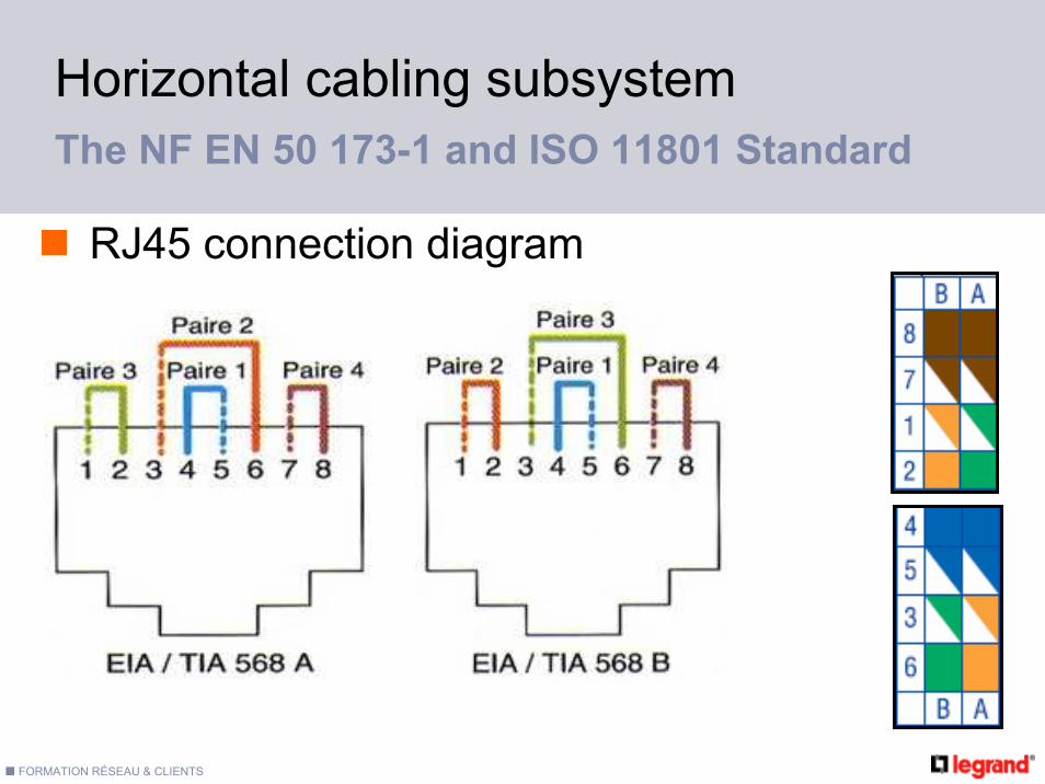
RJ45 connection diagram
Horizontal cabling subsystemThe NF EN 50 173-1 and ISO 11801 Standard

FORMATION RÉSEAU & CLIENTS
Untwistingmaxi 13 mm
RJ45 Use
Horizontal cabling subsystemThe NF EN 50 173-1 and ISO 11801 Standard

FORMATION RÉSEAU & CLIENTS
Cable laying
Horizontal cabling subsystem
don‘t notch copper
Radius of curvatureat least 8 times cable diameter
Avoid sharp angles
Don’t tear cable
Avoid excessive cable torsion
Don’t walk on cableDon’t crush the cablewith tight ties
Don’t pull cable , unwind it
The NF EN 50 173-1 and ISO 11801 Standard

FORMATION RÉSEAU & CLIENTS -
Legrand Cabling SystemLCS

FORMATION RÉSEAU & CLIENTS
LCS5 LCS6
STP
FTP
UTP
A Full system
LCS 10G
Legrand Cabling SystemD
istu
rban
ceof
the
envi
ronm
ent
-
+
Débit100 Mbit/s 1 Gbit/s 10 Gbit/s
FORMATION RÉSEAU & CLIENTS
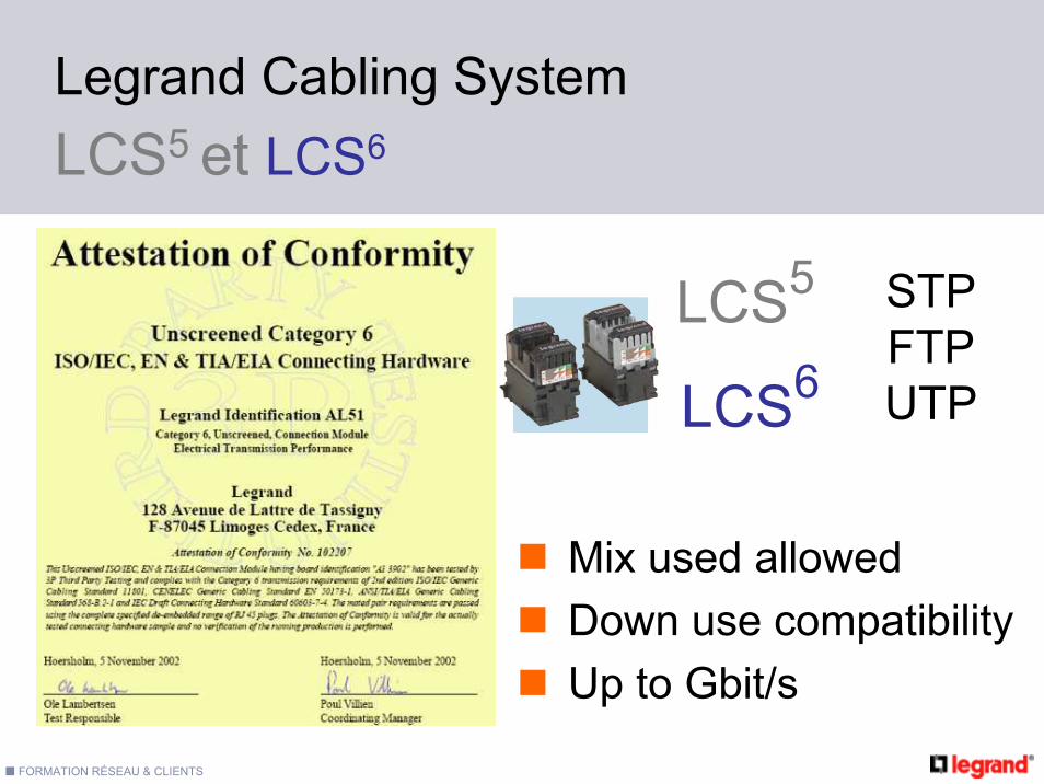
LCS5
LCS6
Mix used allowedDown use compatibilityUp to Gbit/s
STPFTP UTP
LCS5 et LCS6
Legrand Cabling System
FORMATION RÉSEAU & CLIENTS
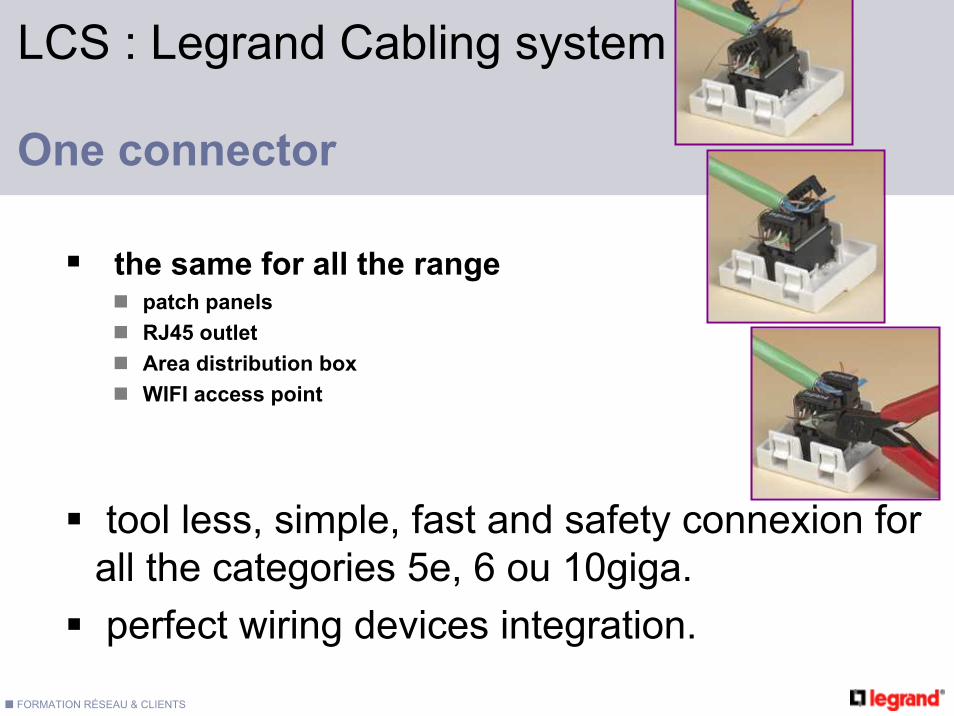
LCS : Legrand Cabling system
One connector
the same for all the rangepatch panelsRJ45 outletArea distribution boxWIFI access point
tool less, simple, fast and safety connexion for all the categories 5e, 6 ou 10giga.perfect wiring devices integration.

FORMATION RÉSEAU & CLIENTS
RJ45, RJ12 and RJ11 compatibilitycable arrival from any directionLow depthre-connection possible (5 times)Installation of the shielding
afterwards
Reliability and safety
Legrand Cabling SystemThe connection
FORMATION RÉSEAU & CLIENTS
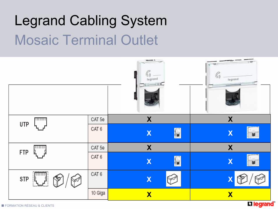
Legrand Cabling SystemMosaic Terminal Outlet
X X
X X
X X
X X
X X
X X

FORMATION RÉSEAU & CLIENTS
10 Gbits/s
Proprietarydevice
The LCS 10 Giga systemLegrand Cabling System
Only STP

FORMATION RÉSEAU & CLIENTS
Cables Cat 5 Cat 6 Cat10giga
Sheath PVC or LSOH (for public area)2 x 4 pairs to safe timeOptimum for EIATIA 568 A colour codeNVP and measuring printed on the sheathU/UTP, F/UTP, SF/UTP, according to
categoryPackaging in boxes (305 m) or reel (500 m)
100ΩLegrand Cabling System

FORMATION RÉSEAU & CLIENTS
The patch cords
An essential part of the system
Cat 5 Cat 6 Cat10giga
Anti-traction sleeve to ensure a radius of curvature and behaviourtractions A precise positioning in the plug
for an optimum connectionAvailable in 1, 2, 3 or 5 m length
100ΩLegrand Cabling System

FORMATION RÉSEAU & CLIENTS
LCS : Legrand Cabling system
One 19" size in the repartitor
same for all the productstelephone blockspatch panel blocksPoE power supply blockoptical block, copper optical converterswitch block, TV splitters
allow modularity.Eaquiped or to be equiped offersAutomatic grounding system.
FORMATION RÉSEAU & CLIENTS
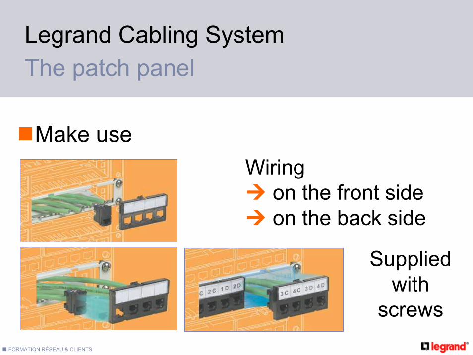
Wiringon the front sideon the back side
The patch panel
Make use
Legrand Cabling System
Suppliedwith
screws

FORMATION RÉSEAU & CLIENTS
Panel LCS5, LCS6, LCS10giga
24 connectors UTP, FTP, STP
Telephone patch panel 48 inputs analogic or digital networks
The equiped panelsLegrand Cabling System

FORMATION RÉSEAU & CLIENTS -
V D ISplitters

FORMATION RÉSEAU & CLIENTS
The splitters
32745 327483274732746
+ ++
Line 1
Line 1
+
Line 1
Line 2
32747
+
Line 1
Line 2
analog analog isdn

FORMATION RÉSEAU & CLIENTS
Splitters for Analog telephone and Ethernet
PLUG12345678
123 6JACK 1
45 78JACK 2
SWITCH
8701 8703
8701
327 45

FORMATION RÉSEAU & CLIENTS -
Legrand Cabling SystemArea distribution box

FORMATION RÉSEAU & CLIENTS
Horizontal wiring: flexibility / rentability
Local technique
2 solutionsFlexibility
AdvantagesEvolutivityRapiditySimplicityRentability
Similar to « consolidation point » of the NF EN 50173-1

FORMATION RÉSEAU & CLIENTS
H ≥ 15 metersCP
Legrand Cabling SystemArea distribution box
Max 12 work area
Max 20 meter

FORMATION RÉSEAU & CLIENTS
2 answers for Area distribution
20 meter max
Legrand Cabling SystemArea distribution box
Area distribution box
RJ45 / Stripped Cord
RJ45 / RJ45 Cord
RJ45 outletwith connector
Rear
Pluggable RJ45

FORMATION RÉSEAU & CLIENTS
Simple connexion withRJ45/RJ45 cordsRentability on installation timeCAT5e , CAT6, UTP and FTPPerformances on CAT5 and CAT6 with specific cords and specific permanent link lengh
With the new rear pluggable RJ45
Legrand Cabling SystemArea distribution box

FORMATION RÉSEAU & CLIENTS -
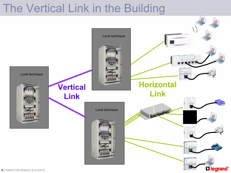
Wiring ArchitectureThe Vertical Link in the Building
FORMATION RÉSEAU & CLIENTS
Local technique
Local technique
Local technique
VerticalLink
Horizontal Link
The Vertical Link in the Building

FORMATION RÉSEAU & CLIENTS
The Vertical Link
Copper backbone ≤ 90m
LCS 10giga offer simple to operate
An alternative of cablingLocal technique
Local technique
Local technique
Câblage vertical

FORMATION RÉSEAU & CLIENTS
Optimal performances 10 Gbit/s with the full system Legrand
The LCS 10 Giga system
Only STP
Local technique
Local technique
Local technique
The Vertical Link
An alternative of cabling

FORMATION RÉSEAU & CLIENTS
The Vertical Link
Copper backbone ≤ 90m
LCS 10giga offer simple to operate
Optical backbonePre-fitted optic links (on demand)Fast crimping ConnectorsEpoxy Connectors
An alternative of cablingLocal technique
Local technique
Local technique
Câblage vertical

FORMATION RÉSEAU & CLIENTS
Cooper offerLCS6 and LCS 10 Giga
Optic offerLCS Optical fiber
Advantages:
The same way to be used for horizontal and vertical links.
full RJ 45 .
Same active devices.
More economic.
Advantages:
Lenght > 90 meters.
Less perturbations.No earth connexion (a light
signal instead of electrical signal in the fiber optic link).
Local technique
Local technique
Local technique
Câblage verticalAn alternative of cabling
The Vertical Link

FORMATION RÉSEAU & CLIENTS
X
X
X NO Cable with plug or cord forbiden
PABX
The Wiring with Two RepartitorsWiring Architecture
Phone panel
Patch panel cat 5 / 6
switch
Phone panel
Patch panel cat 5 / 6
switch

FORMATION RÉSEAU & CLIENTS
Vertical link(Data)
3 X 4 pairs or 6 Optical Fibers
X
X
The Wiring with Two RepartitorsWiring Architecture
PABXPhone panel
Patch panel cat 5 / 6
switch
Patch panel cat 5/6/FO
Phone panel
Patch panel cat 5 / 6
switch
Patch panel cat 5/6/FO

FORMATION RÉSEAU & CLIENTS
Data security
SR1
RB
SR4SR2 SR3
RG
RB
Optionnal link. To be use in cas of main link failure.
First Solution :Repartotor looping
Wiring Architecture

FORMATION RÉSEAU & CLIENTS
SR1
RB
SR4SR2 SR3
RG
RB
Second solution :Redundancy
Several Technologies (Copper/ Optical fibre)
Wiring Architecture
Data security
Optionnal link. To be use in cas of main link failure.

FORMATION RÉSEAU & CLIENTS
SR1
RB
SR4SR2 SR3
RG
RB
Highly criticalinstallations :
Both 1 + 2 solutions
Wiring Architecture
Data security
Optionnal link. To be use in cas of main link failure.

FORMATION RÉSEAU & CLIENTS -
The basics
Optical Fiber

FORMATION RÉSEAU & CLIENTS
Souc
e: C
orni
ng O
ptic
al F
iber
/Cor
ning
Cab
le S
yste
ms
Anal
ysis
Fiber Optic / Applications
Inter Building• 95% fiber & increasing• 50% 1G/ 50% 100M• 10 Gb/s deployments
Riser• 80% fiber • 25% 1Gb/s - 75% 100 Mb/s
Horizontal• <1%Fiber• 10/100/1000 Mb/s
Optical Fiber : the basics

FORMATION RÉSEAU & CLIENTS
The data is carried by sequences of « light present » or « light absent » ("1" et "0")
An interface ,the transciever, transforms the light signal into an electrical signal
2 Fibers needed for a link : « outward » and « inward »
« How does it work ?"Optical Fiber : the basics

FORMATION RÉSEAU & CLIENTS
Patch panel Connector Cable Patch cord
Multimode
- OM1- OM2- OM3
Singlemode
- OS1
Kevlar
Coeur de silice
900 microns
Gaine extérieure2,4 mm
Gaine de silice
Epoxy acrilate
62,5 microns125 microns
250 microns
Silicone 10/100 méga « CAT5 »Gigabit « CAT6 »10 gigabits / 300 m
10 gigabits / km
Optical Fiber : the basics

FORMATION RÉSEAU & CLIENTS
Glass core
kevlar Protection
Glass shield
plastic shield
Multimode
Singlemode
62,5 / 125 µm
50 / 125 µm)
9 / 125 µm = diameter of core
/ core + glass shield
plastic protection
Buffer
The optical fiberOptical Fiber : the basics

FORMATION RÉSEAU & CLIENTS
Multimode : LED or Vcsel
Singlemode :diode laser
Glass shieldCore
The light pathsOptical Fiber : the basics

FORMATION RÉSEAU & CLIENTS
Multimode (62,5 µm et 50 µm) : Mainly used for Local Area Networks (LAN)
Singlemode (9 µm) :Usually reserved for applications requiringhigh data rates over long distances
The optical FibersOptical Fiber : the basics

FORMATION RÉSEAU & CLIENTS
12 Fibers
2 Fibers
4 Fibers
The tight structure or mini break out
The loose structure
The different types of FiberOptical Fiber : the basics
FORMATION RÉSEAU & CLIENTS
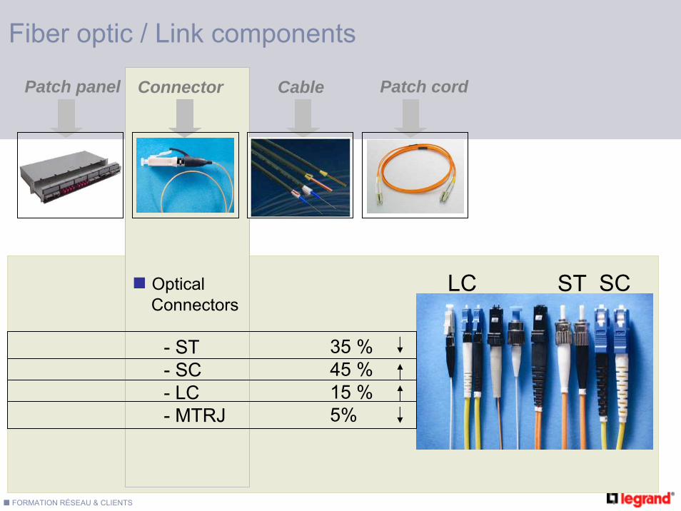
Fiber optic / Link components
Patch panel Connector Cable Patch cord
OpticalConnectors
- ST- SC- LC- MTRJ
35 %45 %15 %5%
ST SCLC

FORMATION RÉSEAU & CLIENTS -
The Legrand optical products
A 8184
LCS Optical offer

FORMATION RÉSEAU & CLIENTS
1Gbit/s on length < 550mOM2 Multimode solution
10 Gbit/s on length < 300mOM3 Multimode solution
10 Gbit/s on length < 2kmOS1 Single mode solution
The performances choice
Optical LCS offer

FORMATION RÉSEAU & CLIENTS
Singlemode unitSC 4 fibers
LC 6 fibers "hight density"
Multimode unitSC 4 fibers
LC 4 fibers
LC 6 fibers "Hight density"
ST 4 fibers
Dedicated to optic drawer and optic cassette
The LCS optical units
Optical LCS offer

FORMATION RÉSEAU & CLIENTS
331 22
Capacity : 6 LCS units
24 fibers SC, ST, LC
36 fibers LC
1U / depth 220mm
4 Fiber coiling accessories , 2 cable glands
Accept the LCS media converter copper/fiber
Optical LCS offer
The optical fiber drawer

FORMATION RÉSEAU & CLIENTS
The optical fiber cassette
Capacity : from 2 to 12 Fibers (2 LCS units)
327 262 to 8 fiber Cassette
ConverterCopper/Optical 2 blocs
Optical LCS offer

FORMATION RÉSEAU & CLIENTS
Fast crimping solutionDedicated connectors
The Installation kit
The new Fast crimping connector tool kit
Optical LCS offer

FORMATION RÉSEAU & CLIENTS
For Indoor, indoor/outdoor, outdor applications
With 4, 6, 12 or 24 Fibers (According to applications)
Multimode : OM1 62,5 / 125 OM2 50 / 125
Monomode : OS1
Connectors ST , SC , LC , other
Packaging in box or in reel (length >50m)
The pre-fitted on demand
Optical LCS offer

FORMATION RÉSEAU & CLIENTS
multimode 50/125µmOM2 : SC, LC, ST
OM3 : SC,LC
singlemode 9/125µmSC,LC 1,2, 3 mètres
Duplex Jumpers and accessory
Optical LCS offer

FORMATION RÉSEAU & CLIENTS
The terminal outlets
Optical LCS offer
ST SC LC
742 28 742 29 74230

FORMATION RÉSEAU & CLIENTS -
WiFi : TechnologieLegrand Cabling System

FORMATION RÉSEAU & CLIENTS
802.11 b/g2,4 GHz (13 channels)11 / 54 Mbit/sCommercial and residential
802.11 a5 GHz (8 channels)54 Mbit/sCommercial premises
WiFi : Standards Legrand Cabling System
Old standard : 802.11b (11Mbit/s )Future standard : 802.11n ( > 200 Mbit/s)

FORMATION RÉSEAU & CLIENTS
Depend on distance between Wifi card to the AP
The rate decrease with the air l’attenuation and obstacles
WiFi : The rate Legrand Cabling System

FORMATION RÉSEAU & CLIENTS
Lower performance than a cable connection around 20Mbit/s
According to the number of users : 20Mbit/s to be shared between the users
Depends on the distance Depends on the environment : wall structure, people, etc…
N Increase the number of access points in order to increase the performance
WiFi : LimitsLegrand Cabling System
WiFi : Share rate
Maximum data Rate
Useful data Rate
Dedicated to network management -codification -indentification / management
Useful data rate to be sharedbetween the users
Available data rate according to distance and environment
Detectionbut no data rate
No Detection

FORMATION RÉSEAU & CLIENTS
Guest access Lan access in the meeting room
54Mbit/s 18Mbit/s 6 Mbit/s
1 Wifi AP
Option 1 : guest / meeting rooms
Legrand Cabling System

FORMATION RÉSEAU & CLIENTS
Global Lan access for employeesHight rate everywhere in the buildingExample : laboratory
18Mbit/s 54Mbit/s 48Mbit/s 36Mbit/s 18Mbit/s
10 bornes Wifi
Option 3 : hight rate wifi
Legrand Cabling System

FORMATION RÉSEAU & CLIENTS
Requested performancesCurrent uses : 1 to 2 Mbit/s
Number of users Ideal performance : 10 users for each Access Point
User area Ideal performance : 1 Access Point for each 100m2!! : Concrete wall = hight performance loses
Ask for the drawing of the building Ask for the following information
Number of usersRequested redundancy Frequency ( a or/and b/g)Requested performance for each user
General ru
les
To be checke
d for
a goo
d quo
tation
WiFi : Project Scope Legrand Cabling System

FORMATION RÉSEAU & CLIENTS
WPA 2 ou 802.11iProfesionnal usesHightest data security encodingInclude 802.1x authentification
WEP Wired equivalent privacyGeneral public usesBasic Encoding, old equipement
WPA Wifi Protected AccessGeneral public usesMore sophisticated encoding, current equipement
WiFi : SecurityLegrand Cabling System

FORMATION RÉSEAU & CLIENTS
PoE: ImplementationLegrand Cabling System

FORMATION RÉSEAU & CLIENTS
The midspan solution : 10/100 Mbit/s
Power supply230/48V
Data
Data+ 48V
48VDATA
Switch
PoE: InjectorLegrand Cabling System

FORMATION RÉSEAU & CLIENTS -
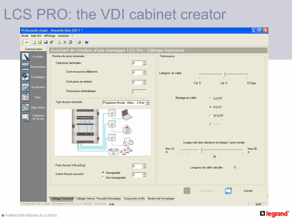
LCS PRO

FORMATION RÉSEAU & CLIENTS
To give an answer to our clients in terms of
Saving of study’s timeDefine a complete, professional and selling file Realize a budget, calculate an affair……
Which purpose ?

FORMATION RÉSEAU & CLIENTS
What about the software ?

FORMATION RÉSEAU & CLIENTS
LCS PRO: the VDI cabinet creator
FORMATION RÉSEAU & CLIENTS
LCS PRO: the VDI cabinet creator

FORMATION RÉSEAU & CLIENTS
LCS PRO: the VDI cabinet creator

FORMATION RÉSEAU & CLIENTS
LCS PRO: the VDI cabinet creator

FORMATION RÉSEAU & CLIENTS
LCS PRO: the VDI cabinet creator

FORMATION RÉSEAU & CLIENTS
LCS PRO: the VDI cabinet creator

FORMATION RÉSEAU & CLIENTS
LCS PRO: the VDI cabinet creator

FORMATION RÉSEAU & CLIENTS -
The standardization
The LV / ELV routing

FORMATION RÉSEAU & CLIENTS
EN 50 174-2
The contents
safety prescritionearth link and equipotentielityprotection against lighting and overvoltage…routing pratice…ELV and LV routing
The practice of installation inside buildings
FORMATION RÉSEAU & CLIENTS
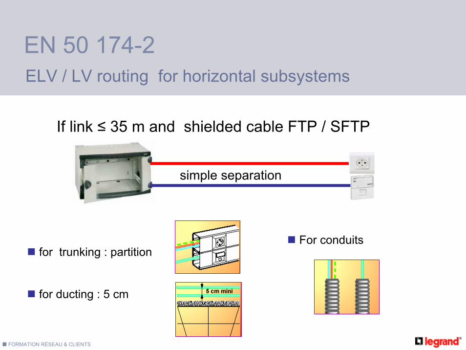
EN 50 174-2ELV / LV routing for horizontal subsystems
simple separation
for trunking : partition
for ducting : 5 cm
If link ≤ 35 m and shielded cable FTP / SFTP
For conduits

FORMATION RÉSEAU & CLIENTS
≤ 15 mSimple
separation
See the followingtable
UTP : 20 cm *FTP : 5 cm *SFTP : 5 cm *
* : with unscreened low voltage cable and no metal partition
EN 50 174-2ELV / LV routing for horizontal subsystems
If link > 35 m or unscreened cable (UTP)

FORMATION RÉSEAU & CLIENTS
EN 50 174-2ELV / LV routing for backbone subsystems
See the followingtable
UTP : 20 cm *FTP : 5 cm *SFTP : 5 cm *
* : with unscreened low voltage cable and no metal partition

FORMATION RÉSEAU & CLIENTS
Aluminium partition
Steel partitionNo separation
Unscreened LVUnscreened ELVUnscreened LVScreened ELV
Screened LVUnscreened ELVScreened LVScreened ELV
200 mm
50 mm
30 mm
0 mm
100 mm
20 mm
10 mm
0 mm
50 mm
5 mm
2 mm
0 mm
EN 50 174-2