Formal Verification of UML-RT Capsules using Model...
114
Department of Computer Science and Engineering CHALMERS UNIVERSITY OF TECHNOLOGY UNIVERSITY OF GOTHENBURG Göteborg, Sweden, June 2009 Formal Verification of UML-RT Capsules using Model Checking Master of Science Thesis in Secure and Dependable Computer Systems MATS CARLSSON LARS JOHANSSON
Transcript of Formal Verification of UML-RT Capsules using Model...

Department of Computer Science and Engineering
CHALMERS UNIVERSITY OF TECHNOLOGY
UNIVERSITY OF GOTHENBURG
Göteborg, Sweden, June 2009
Formal Verification of UML-RT Capsules using
Model Checking
Master of Science Thesis in Secure and Dependable Computer Systems
MATS CARLSSON
LARS JOHANSSON

The Author grants to Chalmers University of Technology and University ofGothenburg the non-exclusive right to publish the Work electronically and in anon-commercial purpose make it accessible on the Internet. The Author war-rants that he/she is the author to the Work, and warrants that the Work doesnot contain text, pictures or other material that violates copyright law.
The Author shall, when transferring the rights of the Work to a third party(for example a publisher or a company), acknowledge the third party aboutthis agreement. If the Author has signed a copyright agreement with a thirdparty regarding the Work, the Author warrants hereby that he/she has obtainedany necessary permission from this third party to let Chalmers University ofTechnology and University of Gothenburg store the Work electronically andmake it accessible on the Internet.
Formal Verification of UML-RT Capsules using Model Checking
Mats Carlsson
Lars Johansson©Mats Carlsson, June 2009.©Lars Johansson, June 2009.
Examiner: Wolfgang Ahrendt
Department of Computer Science and EngineeringChalmers University of TechnologySE-412 96 GoteborgSwedenTelephone + 46 (0)31-772 1000
Department of Computer Science and EngineeringGoteborg, Sweden, June 2009

Abstract
Formal verification methods have successfully been used to ensure correctnessof both hardware and software systems. In contrast to testing methods, thatcan demonstrate the presence of faults in a system, formal methods can provetheir absence.
A department of the telecommunications company Ericsson AB in Gothen-burg, Sweden, uses the UML-RT language to model software used in WCDMAradio base stations. These concurrent and reactive systems can be modeled inthe Eclipse-based RSARTE environment.
Previous work underlines a need of narrowing the gap between softwaredevelopment tools used in industry and formal verification tools. This thesisexamines the feasibility of using model checking to verify properties of UML-RT capsules. We present a prototype tool for generating verification modelsin the Promela language for the model checker Spin. The tool is implementedas a model-to-text transformation using the JET tool and is integrated intoRSARTE.
The result of the work establishes that it, for a subset of constructs inUML-RT, is possible to automate generation of verification models that can beused to demonstrate properties of the original UML-RT capsules. We demon-strate this with example models created in RSARTE.
Keywords formal verification, model checking, model-to-text, Promela,RSARTE, Spin, UML-RT.


Sammanfattning
Formella verifieringsmetoder har med framgang anvants for att sakerstalla kor-rekthet av bade hardvaru- och mjukvarusystem. Till skillnad fran testmetoder,vilka enbart kan visa forekomst av fel i system, kan formella metoder bevisafranvaron av dessa.
En avdelning pa telekommunikationsforetaget Ericsson AB i Goteborg an-vander modelleringsspraket UML-RT for att modellera mjukvara for anvandningi radiobasstationer for WCDMA. Dessa parallella och reaktiva system kan mo-delleras i den Eclipse-baserade utvecklingsmiljon RSARTE.
Tidigare arbeten understryker ett behov av att minska avstandet mellan in-dustriella mjukvaruutvecklingsverktyg och verktyg for formell verifiering. Dettaarbete utforskar mojligheten att anvanda model checking for att verifiera egen-skaper hos UML-RT-kapslar. Vi presenterar ett prototypverktyg for att gene-rera verifieringsmodeller i spraket Promela, som anvands av model checking-verktyget Spin. Prototypverktyget ar implementerat i form av en model-to-text -transformation med hjalp av verktyget JET och ar integrerat i RSARTE.
Resultatet av arbetet faststaller att det, for en delmangd av byggstenarna iUML-RT, ar mojligt att automatisera framstallning av verifieringsmodeller, somdarefter kan anvandas for att pavisa egenskaper hos de ursprungliga UML-RT-kapslarna. Vi demonstrerar detta med hjalp av ett antal exempelmodeller somskapats med RSARTE.
Sokord formell verifiering, model checking, model-to-text, Promela,RSARTE, Spin, UML-RT.


Preface
This report is the result of a Master of Science thesis project in the program Se-cure and Dependable Computer Systems at Chalmers University of Technologyin Gothenburg, Sweden. The work has been conducted between February andJune of 2009 for Ericsson AB, at a department developing application softwarefor WCDMA radio base stations.
The examiner for the thesis has been Dr. Wolfgang Ahrendt from the De-partment of Computer Science and Engineering at Chalmers University of Tech-nology, whose advice and support we gratefully acknowledge. Our supervisorsat Ericsson have been Anders Borghed, Peter Eriksson and Sebastian Holmgren,all of whom have provided much appreciated support, guidance and encourage-ment throughout our work.
v

Contents
Preface v
1 Introduction 11.1 Background . . . . . . . . . . . . . . . . . . . . . . . . . . . . . . 21.2 Aim . . . . . . . . . . . . . . . . . . . . . . . . . . . . . . . . . . 31.3 Limitations . . . . . . . . . . . . . . . . . . . . . . . . . . . . . . 31.4 Disposition . . . . . . . . . . . . . . . . . . . . . . . . . . . . . . 4
2 Theory 52.1 Formal Verification . . . . . . . . . . . . . . . . . . . . . . . . . . 52.2 Model Checking . . . . . . . . . . . . . . . . . . . . . . . . . . . . 6
2.2.1 Model checking workflow . . . . . . . . . . . . . . . . . . 62.3 The Spin model checker . . . . . . . . . . . . . . . . . . . . . . . 7
2.3.1 The Promela specification language . . . . . . . . . . . . 82.3.2 A Promela example . . . . . . . . . . . . . . . . . . . . . 82.3.3 Property specification in Spin using LTL . . . . . . . . . 102.3.4 LTL property verification . . . . . . . . . . . . . . . . . . 112.3.5 Problem space reduction . . . . . . . . . . . . . . . . . . . 11
3 Method 133.1 Configuration of test system . . . . . . . . . . . . . . . . . . . . 14
4 Description of modeling environment 154.1 Historic context . . . . . . . . . . . . . . . . . . . . . . . . . . . . 15
4.1.1 Modeling reactive systems . . . . . . . . . . . . . . . . . . 154.2 Modeling constructs in UML-RT . . . . . . . . . . . . . . . . . . 164.3 UML-RT tools at the department . . . . . . . . . . . . . . . . . . 17
5 Previous work and tools for software model verification 195.1 vUML . . . . . . . . . . . . . . . . . . . . . . . . . . . . . . . . . 195.2 Hugo . . . . . . . . . . . . . . . . . . . . . . . . . . . . . . . . . . 205.3 VIP and v-Promela . . . . . . . . . . . . . . . . . . . . . . . . . . 205.4 TABU . . . . . . . . . . . . . . . . . . . . . . . . . . . . . . . . . 20
vi

5.5 SMARRT . . . . . . . . . . . . . . . . . . . . . . . . . . . . . . . 215.6 Summary and conclusions of review . . . . . . . . . . . . . . . . 21
6 Prototype system integrating RSARTE with Spin 226.1 Verification model extraction options . . . . . . . . . . . . . . . . 22
6.1.1 Code generation in RSARTE using JET . . . . . . . . . . 236.2 Verification model overview . . . . . . . . . . . . . . . . . . . . . 25
6.2.1 Modeling capsule interaction with the environment . . . . 256.2.2 Mapping concepts in UML-RT to Promela . . . . . . . . 266.2.3 Signal producers and consumers . . . . . . . . . . . . . . 276.2.4 Embedded Promela code . . . . . . . . . . . . . . . . . . 286.2.5 Property verification . . . . . . . . . . . . . . . . . . . . . 28
6.3 Verification model options . . . . . . . . . . . . . . . . . . . . . . 286.4 JET transformation structure . . . . . . . . . . . . . . . . . . . . 29
7 Property specification 307.1 Internally specified properties . . . . . . . . . . . . . . . . . . . . 307.2 Externally specified properties . . . . . . . . . . . . . . . . . . . 317.3 Properties of primary interest . . . . . . . . . . . . . . . . . . . . 32
7.3.1 Signal handling guarantee . . . . . . . . . . . . . . . . . . 327.3.2 Trap detection . . . . . . . . . . . . . . . . . . . . . . . . 32
7.4 Limitations in property specification . . . . . . . . . . . . . . . . 33
8 Model examples 348.1 A model of a traffic light system . . . . . . . . . . . . . . . . . . 34
8.1.1 Model description . . . . . . . . . . . . . . . . . . . . . . 348.1.2 Properties . . . . . . . . . . . . . . . . . . . . . . . . . . 358.1.3 First version . . . . . . . . . . . . . . . . . . . . . . . . . 358.1.4 Second version . . . . . . . . . . . . . . . . . . . . . . . . 368.1.5 Third version . . . . . . . . . . . . . . . . . . . . . . . . . 37
8.2 A model of an electronic lock . . . . . . . . . . . . . . . . . . . . 428.2.1 Model description . . . . . . . . . . . . . . . . . . . . . . 428.2.2 Properties . . . . . . . . . . . . . . . . . . . . . . . . . . 438.2.3 First version . . . . . . . . . . . . . . . . . . . . . . . . . 438.2.4 Second version . . . . . . . . . . . . . . . . . . . . . . . . 44
8.3 The dining philosophers . . . . . . . . . . . . . . . . . . . . . . . 458.3.1 Problem scenario . . . . . . . . . . . . . . . . . . . . . . . 458.3.2 Model description . . . . . . . . . . . . . . . . . . . . . . 478.3.3 Properties . . . . . . . . . . . . . . . . . . . . . . . . . . 478.3.4 Model implementation . . . . . . . . . . . . . . . . . . . . 48
8.4 A model with intentional errors . . . . . . . . . . . . . . . . . . . 498.4.1 Model description and properties . . . . . . . . . . . . . . 49
8.5 A complexity experiment . . . . . . . . . . . . . . . . . . . . . . 50
9 Results 559.1 Traffic light system . . . . . . . . . . . . . . . . . . . . . . . . . . 55
9.1.1 First version . . . . . . . . . . . . . . . . . . . . . . . . . 559.1.2 Second version . . . . . . . . . . . . . . . . . . . . . . . . 579.1.3 Third version . . . . . . . . . . . . . . . . . . . . . . . . . 59
9.2 Electronic lock . . . . . . . . . . . . . . . . . . . . . . . . . . . . 61

9.2.1 First version . . . . . . . . . . . . . . . . . . . . . . . . . 619.2.2 Second version . . . . . . . . . . . . . . . . . . . . . . . . 64
9.3 Dining philosophers . . . . . . . . . . . . . . . . . . . . . . . . . 649.4 Model with intentional errors . . . . . . . . . . . . . . . . . . . . 709.5 Complexity experiment . . . . . . . . . . . . . . . . . . . . . . . 70
10 Conclusions 7310.1 Answers to questions . . . . . . . . . . . . . . . . . . . . . . . . . 7310.2 Discussion . . . . . . . . . . . . . . . . . . . . . . . . . . . . . . 77
10.2.1 Benefits and drawbacks . . . . . . . . . . . . . . . . . . . 7710.2.2 Primary application areas . . . . . . . . . . . . . . . . . . 7710.2.3 Important verification issues . . . . . . . . . . . . . . . . . 78
10.3 Future work . . . . . . . . . . . . . . . . . . . . . . . . . . . . . . 7910.3.1 Properties . . . . . . . . . . . . . . . . . . . . . . . . . . . 7910.3.2 Model transformation . . . . . . . . . . . . . . . . . . . . 7910.3.3 Scalability . . . . . . . . . . . . . . . . . . . . . . . . . . . 80
A Promela model example 85
B JET transformation templates 95

List of Figures
2.1 Outline of a general model checking workflow. . . . . . . . . . . . 7
4.1 Example of actors in ROOM . . . . . . . . . . . . . . . . . . . . 16
6.1 Prototype system outline . . . . . . . . . . . . . . . . . . . . . . 246.2 Illustration of capsule interaction . . . . . . . . . . . . . . . . . . 256.3 JET transformation project structure . . . . . . . . . . . . . . . 29
8.1 Traffic light capsule state machine and structure diagram . . . . 388.2 Original controller capsule state machine and structure diagram . 398.3 Traffic light system sequence diagram . . . . . . . . . . . . . . . 408.4 Intersection capsule structure diagram . . . . . . . . . . . . . . . 408.5 Controller capsule modified state machine diagram . . . . . . . . 418.6 Lock capsule state machine and structure diagram . . . . . . . . 448.7 Lock capsule modified state machine diagram . . . . . . . . . . . 458.8 The Dining philosophers . . . . . . . . . . . . . . . . . . . . . . . 458.9 Table capsule structure diagram . . . . . . . . . . . . . . . . . . 488.10 Philosopher capsule state machine and structure diagram . . . . 518.11 Butler capsule state machine and structure diagram . . . . . . . 528.12 Chopstick capsule state machine and structure diagram . . . . . 538.13 Demonstration capsule state machine and structure diagram . . . 54
9.1 Error scenario: first traffic light system model, property 1 . . . . 569.2 Error scenario: second traffic light system model, property 3 . . . 609.3 Error scenario: first electronic lock model, property 2 . . . . . . . 639.4 Error scenario: first electronic lock model, property 4 . . . . . . . 659.5 Error scenario: second electronic lock model, property 1 . . . . . 669.6 Error scenario: demonstration model, property 1 . . . . . . . . . 719.7 Results: Complexity experiment . . . . . . . . . . . . . . . . . . . 72
ix

Listings
2.1 Promela model vulnerable to a data race situation. . . . . . . . . 92.2 Spin output showing an assertion violation . . . . . . . . . . . . . 108.1 Transition effect code of the first traffic light system controller . 368.2 Stimulus process for the electronic lock capsule . . . . . . . . . . 429.1 Results: first traffic light system model, property 1 . . . . . . . . 569.2 Results: second traffic light system model, property 1 . . . . . . 579.3 Results: second traffic light system model, property 2 . . . . . . 589.4 Results: second traffic light system model, property 3 . . . . . . 589.5 Results: third traffic light system model, property 1 . . . . . . . 599.6 Results: third traffic light system model, property 2 . . . . . . . 619.7 Results: third traffic light system model, property 3 . . . . . . . 629.8 Results: first electronic lock model, property 1 . . . . . . . . . . 629.9 Results: first electronic lock model, property 2 . . . . . . . . . . 639.10 Results: first electronic lock model, property 3 . . . . . . . . . . 649.11 Results: first electronic lock model, property 4 . . . . . . . . . . 659.12 Results: second electronic lock model, property 1 . . . . . . . . . 669.13 Results: dining philosophers model, property 1 . . . . . . . . . . 679.14 Results: dining philosophers model, property 2 . . . . . . . . . . 689.15 Results: dining philosophers model, property 3 . . . . . . . . . . 699.16 Results: dining philosophers model, property 4 . . . . . . . . . . 699.17 Results: demonstration model, property 1 . . . . . . . . . . . . . 709.18 Results: demonstration model, property 2 . . . . . . . . . . . . . 71A.1 Promela code for a demonstration capsule model. . . . . . . . . 86B.1 Main transformation template . . . . . . . . . . . . . . . . . . . . 96B.2 State machine generation template . . . . . . . . . . . . . . . . . 97
x

Terminology
Acronyms
CTL Computation Tree Logic
FSM Finite State Machine
JET Java Emitter Template
LTL Linear Time Logic
OTD ObjecTime Developer
OTI Object Technology International
Promela Process Meta Language
PSL Property Specification Language
ROOM Real-Time Object-Oriented Methodology
RoseRT IBM Rational Rose RealTime
RSARTE Rational Software Architect Real Time Edition
SMARRT Static Model checking and Analysis for Rose RealTime
SMV Symbolic Model Verifier
Spin Simple Promela Interpreter
TABU Tool for the Active Behaviour of UML
UML-RT UML Real Time
UML Unified Modeling Language
VIP Visual Interface to Promela
WCDMA Wideband Code Division Multiple Access
xi

XMI XML Metadata Interchange
XML Extensible Markup Language
XPath XML Path Language

CHAPTER 1
Introduction
The presence of errors in computer systems, both originating from incorrectdesign choices as well as from implementation mistakes, remains a challenge inthe industry. Despite traditional validation and verification counter measures,such as simulation and testing, mistakes are costly. Figures released in 2002estimated that the industry cost of software faults in the United States alone,approached 60 billion dollars (NIS 2002).
Faults may be present in the design or implementation of a system andcertain conditions may activate a fault, causing an error to be produced. Unlesssuch an error is properly handled, it may propagate and cause the system outputto deviate from the specified output, resulting in a failure (Avizienis, Laprie,Randell & Landwehr 2004).
Software and hardware testing can expose faults that may exist in the sys-tem, provided that a test case has been constructed, which activates the faultand exposes the resulting error. The task of constructing suitable test cases isnot trivial and attempting to ensure that all faults are found by testing the sys-tem exhaustively is often an impossible task (Clarke, Grumberg & Peled 1999,p. 2). As will be illustrated by the following two examples, gathering even over-whelming amounts of empirical evidence to support a claim does not prove itscorrectness.
The first example is the floating point unit of Pentium processors which wasfound to be flawed in 1994. The fault lay in a lookup table used for divisionoperations and was due to entries missing from the table. This, in turn, causedcertain instructions related to floating point division to produce results deviatingfrom the correct output. The probability of activating the fault by applying oneof the affected instructions to a randomly chosen value from the input spacewas 1 to 9 billion, according to analysis by Intel (Int 1994).
A more theoretical example of a problem which is difficult to analyze cor-rectly using testing is the following: We can claim that there exists no positiveinteger n such that 991 · n2 + 1 is a perfect square, apart from the trivial solu-tion of n = 0. This claim happens to be incorrect, but the first positive integer
1
Chapter 1. Introduction
solution does not occur until
n = 12, 055, 735, 790, 331, 359, 447, 442, 538, 767
(Rotman 1998), suggesting that it is difficult to falsify the hypothesis usingtesting. The only feasible method of refuting the hypothesis is to use a methodthat relies on proofs rather than on an exhaustive search.
Formal verification methods rely on techniques from logic and mathemat-ics, in practice usually supported by computer tools, to prove properties aboutsystems. Such methods have been used successfully in the development of sys-tems that require a very high degree of confidence that the product meets itsspecification.
There are many reasons to why a system may demand rigorous design valida-tion. Safety requirements, such as in air traffic control systems or flight controlsystems; security requirements, such as in implementations of cryptographicprotocols; or the cost of failure may all motivate the use of formal verifica-tion. Legal requirements, such as in digital signing of programs or documentsto ensure authenticity and non-repudiation; certification requirements; or legalimplications of failure in any of the above scenarios may also warrant the useof formal methods (Elamkulam, Glazberg, Rabinovitz, Kowlali, Gupta, Kohli,Dattathrani & Macia 2006).
1.1 Background
The telecommunications company Ericsson AB develops software for radio basestations for the Wideband Code Division Multiple Access (WCDMA) standardat a department at Lindholmen in Gothenburg (hereinafter referred to only asthe “department”). The software is developed with visual tools that supportmodeling in a dialect of UML and C++ code is then generated directly fromthe models. The modeling language in use at the department is UML RealTime (UML-RT), currently supported by the tool IBM Rational Rose RealTime(RoseRT) but being superseded by the Rational Software Architect Real TimeEdition (RSARTE) tool.
UML-RT, described in more detail in Chapter 4, is for example used atthe department to model hierarchies of concurrently operating system compo-nents called capsules, whose behaviors are defined using state machines and thatcommunicate with each other using message passing. The behavior of a singlecapsule can be very complex and the combined behavior of several capsules evenmore so.
Testing of both normal and failure cases is performed at the department.However, there is always a possibility that faults in capsules remain undiscoveredand appear when least expected. In the words of Dijkstra (1970, p. 7), “Programtesting can be used to show the presence of bugs, but never to show theirabsence!” For this reason, the department is interested in understanding andexploring the possibility of using formal verification methods as a complementto the testing procedures in current use.
2

1.2. Aim
1.2 Aim
The purpose of the thesis is to evaluate how formal verification can be integratedin the model based development process used for developing the applicationsoftware for WCDMA base stations at the department. This thesis aims toprovide answers to the following questions:
1. What methods and tools for formal verification of software models areavailable in the academic, industrial or open source communities? Wedecompose this question into the following sub-questions:
(a) What approach could be used as a basis for verification of modelsdeveloped at the department?
(b) Are there existing tools for formal verification that can be directlyused to verify properties of models in the development environmentat the department? If this is not the case, are there existing toolsthat can serve as a foundation for implementing such a tool?
(c) Can these tools be integrated into the development environment atthe department?
2. What properties are of interest to the department to verify?
3. How should models be developed to allow such properties to be formallyverified using the chosen method?
4. What can be gained from applying formal verification methods to thedepartment’s software models?
Furthermore, since it is of interest to the department that the viewpoints ofthe software designer are considered throughout the work, decisions regardingthe verification approach, tool selection and design choices will be made withthe potential future user of the tool in mind.
1.3 Limitations
Any prototypical tool implemented is intended to serve as a proof of concept,outlining a possible method for property verification. For this reason, it is notan aim to handle models of the same size or complexity as can be found inthe department’s products. In addition to varying greatly in complexity, themodels developed at the department are produced with tools that support alarge number of modeling constructs. The scope of this thesis is limited to asubset of the available constructs (see Section 6.2.2).
The verification is intended to target only properties of the model and not tomake any claims about correctness of code embedded in the model. Therefore,no code analysis methods for extracting information from embedded code areconsidered. This in turn implies that any fully automated verification procedureis beyond the scope of this thesis.
Any model properties related to time (in the sense that can be measurednumerically, not in the sense of ordering of events) will be either treated on anabstract level or be completely disregarded. This is a common practice whenmodeling concurrent or distributed systems, because as Ben-Ari (2008, p. 173)explains,
3

Chapter 1. Introduction
“Algorithms for these systems are designed to be independent of thespeed of execution of a process or the speed at which a message isdelivered, so it is sufficient to know that there are no errors causedby interleaving statements and messages.”
1.4 Disposition
Abbreviations, terminology and names used in this disposition are explained asthey are later introduced. The remainder of this thesis is ordered as follows:
Chapter 2 presents an introduction to the field of formal verification, as wellas a brief introduction to the verification tool Spin, which is used in theprototype tool.
Chapter 3 presents the method chosen for addressing the questions that thisthesis aims to answer.
Chapter 4 presents the background of UML-RT and a description of the mod-eling tools used at the department. A presentation of modeling conceptsand building blocks of UML-RT is also given, together with an explana-tion of the link between UML-RT and the two modeling tools RoseRT andRSARTE.
Chapter 5 presents a survey of previous work in the field of software modelverification. An assessment of previous work and existing verification toolsas they relate to the modeling language used at the department is alsogiven.
Chapter 6 presents a description of a prototype tool implemented for integrat-ing the model checker Spin with the modeling tool RSARTE.
Chapter 7 presents a categorization of system properties and a descriptionof how such properties may be specified. The two properties that are ofprimary interest to the department are also presented.
Chapter 8 describes the models and presents the properties that are verifiedusing the prototype tool.
Chapter 9 presents verification results for each model and property.
Chapter 10 presents answers to the questions that the thesis aims to answer.A discussion on the limitations of the chosen verification approach andprototype tool is presented, together with suggestions for possible futureextensions and improvements of the work.
Appendix A presents the verification model for a capsule discussed in Sec-tion 8.4.
Appendix B contains two sample JET templates that are part of the proto-type tool.
4

CHAPTER 2
Theory
This chapter provides an introduction to the use of model checking tools, toformally verify systems. We describe formal specification languages using themodel checker Simple Promela Interpreter (Spin) and its input languages as theexample.1
2.1 Formal Verification
The objective of formal verification is to extend beyond what is possible toachieve using testing procedures, by providing a formal proof that a systemconforms with design specifications. The system in question can, for example,be a hardware circuit or communication protocol (Clarke et al. 1999), or asoftware design (Holzmann 2003). The two major methods used to formallyverify systems are deductive verification and model checking (Clarke et al. 1999).
Deductive verification relies on using a system of axioms and application ofinference rules, to prove a system correct. This can be, and was originally done,manually, but generally requires expertise in both the area of the target systemand in mathematics or logic. Tools such as KeY2 and HOL Light3 have beendeveloped to aid the user by automatically providing a complete proof, or byserving as a proof assistant that guides the user’s interaction with a theoremprover. According to Ben-Ari (2008, p. 23), one advantage of deductive methodsis that they may allow verification of systems where the size of the state spacewould otherwise be limiting.
1Spin is used as the example since it is used in later parts of this thesis. A motivation forthis choice is given in Section 5.6.
2http://www.key-project.org3http://www.cl.cam.ac.uk/~jrh13/hol-light/
5

Chapter 2. Theory
2.2 Model Checking
The model checking field originated in the early 1980s as a method for addressingthe problem of verifying concurrent programs (Clarke 2008). Such programs arehard to debug due to the frequent difficulty of reproducing errors (Clarke 2008).If the tasks executing concurrently in the program communicate or otherwisedepend upon each other, it can very quickly become problematic to establishunder what conditions deadlocks may occur or mutual exclusion constraints maybe violated, due to the large number of possible ways in which multiple tasksmay interleave.
Clarke et al. (1999) partition the process of model checking a design intothree steps; modeling, specification and verification.
Modeling The design must be represented or encoded in some formal lan-guage. This can be done by directly writing code in the language of themodel checker, or by transforming some other description, such as sourcecode, into the language of the model checker. This transformation can bedone manually, or by using some automated pre-processor (see for exam-ple Beyer, Henzinger, Jhala & Majumdar (2007) and Holzmann & Smith(1999)).
Specification The properties that the model should satisfy must also be statedin an unambiguous, formal notation. This requires firstly an understand-ing of what properties are of interest to verify, and secondly a languagesufficiently expressive to capture those properties. Examples of such lan-guages are Linear Time Logic (LTL)4 and Computation Tree Logic (CTL),both members in the temporal logic family.
Verification The tool will accept the model and the specification and deter-mine whether the design meets the requirements. The tool will determineif, for every possible path through an algorithm or for every possible stateof a hardware circuit, the model satisfies the specification.
This task is not performed with brute-force methods since that would beinfeasible for most target systems. For example, circuits with more than1090 states have been verified using model checking (Emerson 2008) whichis far beyond the reach of any brute-force algorithm.
The two dominating model checking methods are divided by Holzmann(2003) into those using symbolic verification methods and those using ex-plicit verification methods. An example falling into the first category isthe Symbolic Model Verifier (SMV) tool that is based on Ordered Bi-nary Decision Diagram manipulation techniques (Clarke et al. 1999). TheSpin tool falls into the second category and uses partial order reduction(see section 2.3.5) as part of its strategy to cope with the state explosionproblem (Holzmann 2003).
2.2.1 Model checking workflow
The practical usage of a model checker will typically follow the workflow outlinedin Figure 2.1. A design is transformed into a description suitable for the model
4LTL is described in more detail in Section 2.3.3.
6
2.3. The Spin model checker
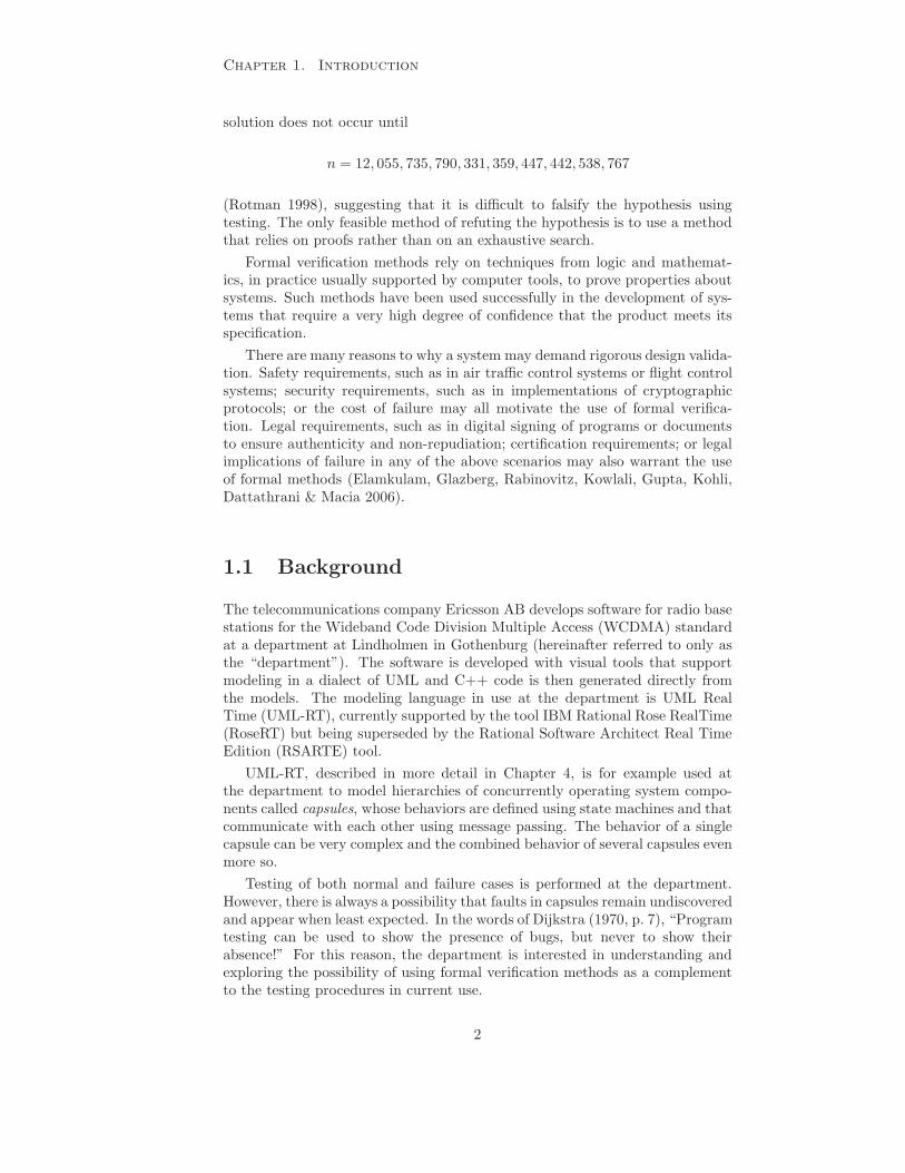
checker, either manually or with the aid of tools, and a specification of a wantedor unwanted behavior is captured as a property. The result produced by themodel checker on the basis of this information is either confirmation that theproperty has been verified to hold, or an error trace showing how the propertycan be invalidated (Clarke 2008, pp. 2–3). If given sufficient resources, themodel checking tool will always terminate with an answer (Clarke 2008, pp. 3).
D e s i g n o fp r o g r a m o r
c i rcu i t
P r e - p r o c e s s o r P r o p e r t y
M o d e l c h e c k e r
O K
T r a c e o r c o u n t e r -e x a m p l e
Y e s
N o
P r o p e r t yh o l d s ?
S p e c i f i c a t i o n
Figure 2.1: Outline of a general model checking workflow.
2.3 The Spin model checker
The Spin model checker was originally developed at Bell Labs in the begin-ning of the 1980s (Holzmann 1997) and has since been continuously developed.Spin has been available since 1991 and can be used freely for educational pur-poses (Holzmann 2003). Commercial use of Spin does not command a fee butrequires a license agreement to be accepted (LIC 2001).
Spin is a system for proving properties of software systems by enabling adesigner to create abstract models of the target system, specify properties thatmust hold for the model and verify if this is in fact the case or not.5 Spin allowsthe designer to explore — through simulation or verification — system behaviorwhich results from interaction between processes.
Spin uses verification models specified in Process Meta Language (Promela)(Holzmann 1997) and can be used in several ways including random, interac-tive or guided simulation mode, and verification mode. When used as randomsimulator, Spin will follow one randomly chosen execution path of the modeledsystem. In interactive simulation mode, the user is called upon to decide howto proceed when a choice must be made between possible execution paths. Inguided simulation mode, Spin follows a trail file that describes a specific execu-tion path through the system.
5For the underlying theory of how models and properties are handled by Spin to performthe verification, see Holzmann (1997).
7

Chapter 2. Theory
Note that no amount of repeated random simulation guarantees that everyexecution path is eventually taken. The results from a simulation run is onlyapplicable to the particular execution path through the system selected in thatspecific simulation run. A verification run is therefore necessary to verify claimsabout all of the possible simulation runs, i.e., about every possible executionpath of the system. If Spin finds that a model does not satisfy a particularproperty, then a trail file is generated. The file details the exact steps thatproduces a violation of the property and can be used in guided simulation modeto replay the execution (Holzmann 2003, pp. 245–252).
2.3.1 The Promela specification language
Promela is a specification language, visually resemblant of C, for describingmodels of concurrent systems. The number of constructs supported by thelanguage is intentionally small and the focus of those constructs is on describingbehavior and interaction between system components, rather than computation.The reason for this is that, “Promela is not meant to be an implementationlanguage but a systems description language.” Holzmann (2003, p. 8)
The Promela language provides features for describing concurrently execut-ing processes and communication between such processes using message passingover buffered or unbuffered message channels. Promela also makes it easy tomodel indeterministic choice through the use of control statements similar toDijkstra’s guarded commands (Holzmann 2003, p. 407).6 However, there are nofeatures for returning values from function calls, no support for floating pointnumbers and no notion of time beyond event ordering.(Holzmann 2003, p. 8)
2.3.2 A Promela example
It is beyond the scope of this thesis to describe details of Spin and Promela, butListing 2.1 serves to give an impression of syntax and concepts of the Promelalanguage. For a complete description of Spin, Promela and further examplessee, e.g., Holzmann (2003), Ben-Ari (2008) and Holzmann (1997).
The example models a scenario with two bank tellers and two bank cus-tomers, communicating in pairs using message passing over a channel. Thecustomers share one bank account with an initial balance of 60 currency units.The customers both carry out three transactions, choosing indeterministicallybetween attempting to withdraw or to deposit 50 currency units. When a bankteller receives an order to withdraw money, the balance of the account is checkedto ensure that it holds sufficient funds. If this is the case then the balance isdecreased and the teller then verifies that the balance has not somehow fallenbelow zero (see lines 14–15 in Listing 2.1). When a bank teller receives an orderto deposit money, the balance is increased.
A verification run with Spin can be used to find a process interleaving thatcan cause the account balance to fall below zero. The resulting trail file canin turn be used to playback the execution and locate the error. Listing 2.2presents condensed output from the execution playback. It demonstrates thatthe assertion violation occurs when the first teller is interrupted in the with-drawal procedure after checking the account balance, but before recording the
6See for example lines 28–31 in Listing 2.1.
8

2.3. The Spin model checker
Listing 2.1: Promela model vulnerable to a data race situation.
1 short ba lance = 60 ;2
3 mtype = {withdraw 50 , depo s i t 50 } ;4
5 chan channe l a = [ 0 ] of { mtype } ;6 chan channe l b = [ 0 ] of { mtype } ;7
8 proctype t e l l e r (chan in ) {9 end :
10 do11 : : in ? withdraw 50 −>
12 i f13 : : ba lance >= 50 −>
14 ba lance = ba lance − 50 ;15 assert ( ba lance >= 0) ;16 : : else −> skip ;17 f i18 : : in ? depo s i t 50 −>
19 ba lance = ba lance + 50 ;20 od21 }22
23
24 proctype customer (chan out ) {25 byte t r a n s a c t i o n s = 3 ;26 do27 : : t r a n s a c t i o n s > 0 −>
28 i f29 : : out ! withdraw 50 ;30 : : out ! depo s i t 50 ;31 f i ;32 t r a n s a c t i o n s = t r an s a c t i o n s − 1 ;33 : : else −> break ;34 od35 }36
37
38 in i t {39 atomic {40 run t e l l e r ( channe l a ) ;41 run customer ( channe l a ) ;42 run t e l l e r ( channe l b ) ;43 run customer ( channe l b ) ;44 }45 }
9

Chapter 2. Theory
Listing 2.2: Condensed Spin output demonstrating a process interleaving re-sulting in an assertion violation.
1 proc 2 ( customer 1) [ out ! withdraw 50 ]2 proc 1 ( t e l l e r 1) [ in ?withdraw 50 ]3 proc 1 ( t e l l e r 1) [ ( ( ba lance >=50)) ]4
5 proc 4 ( customer 2) [ out ! withdraw 50 ]6 proc 3 ( t e l l e r 2) [ in ?withdraw 50 ]7 proc 3 ( t e l l e r 2) [ ( ( ba lance >=50)) ]8
9 proc 3 ( t e l l e r 2) [ ba lance = ( balance−50) ]10 proc 3 ( t e l l e r 2) [ a s s e r t ( ( balance>=0)) ]11
12 proc 1 ( t e l l e r 1) [ ba lance = ( balance−50) ]13 sp in : Error : a s s e r t i o n v i o l a t ed14 sp in : t ex t o f f a i l e d a s s e r t i o n : a s s e r t ( ( balance>=0))15 proc 1 ( t e l l e r 1) [ a s s e r t ( ( balance>=0)) ]
new balance. The consequence is that the tellers are able to make a withdrawaleach, based on the same account balance, incorrectly causing a final negativebalance.
2.3.3 Property specification in Spin using LTL
The properties that we wish to prove or refute for a given Promela model mustbe specified in some formal notation. The example in Section 2.3.2 showed a cor-rectness claim specified using an assertion statement, but Spin also supports ver-ification of correctness claims specified in LTL (Holzmann 1997). This temporallogic allows specifications that refer to the future (Huth & Ryan 2004, p. 175) byextending propositional logic formulas with temporal connectives (Ben-Ari 2008,pp. 71–72).
The operators inherited from propositional calculus are: negation, conjunc-tion, disjunction, implication and equivalence. In addition to this, LTL providesthe temporal operators always, eventually, (strong) until, the dual of until (com-monly referred to as release) and next. These allow us to state claims about thebehavior of the Promela model and to use Spin to assert or refute those claims.See Holzmann (2003, pp. 135–136) for a complete description of the semanticsof the operators and the syntax used in Spin.
Always (�) captures properties that are related to invariance, e.g., the formula� p specifies that condition p always holds true. The operator is written[] in Promela.
Eventually (♦) captures properties related guaranteed behavior, e.g. the for-mula ♦ p specifies that the condition p holds in the current state or willhold in some future state. The operator is written <> in Spin.
Until (U) captures properties of relative behavior, e.g. p U q specifies thatthe condition p must hold until q becomes true (now or in the future).
10

2.3. The Spin model checker
The definition of weak until does not require that q ever becomes true,while the definition of strong until does require that q at some point holdstrue. Spin uses the strong definition of until (Ben-Ari 2008, p. 91). Theoperator is written U in Spin.
Release (R) is the dual of the strong until operator, e.g., p R q specifies thatq holds true until p becomes true, which releases q. If p never becomestrue, then q must hold forever. The operator is written V in Spin.
Next (X ) captures properties that relate a state to its successor, e.g., X p
holds in the current state iff p holds in the next state. The operator iswritten X in Spin.
The next operator requires caution because of the restrictions on its use thatare imposed by Spin. The default behavior of Spin is to disallow the use of thenext operator, due to the possibility of conflicts with the state space reductionmethod used by Spin (see Section 2.3.5).
2.3.4 LTL property verification
Spin can be used both to prove desired behaviors (i.e., properties that shouldalways hold) or error behaviors (i.e., properties that should never hold). Forreasons of verification efficiency, Spin does not attempt to prove that a behavioris guaranteed; instead Spin attempts to show how a behavior claimed to beimpossible can in fact be achieved (Holzmann 1997, p. 97).
This means that to prove a desired behavior, an LTL formula that capturesthat behavior is specified and then negated. Spin then attempts to show a run ofthe system in which the negated formula holds. If Spin succeeds, then the desiredbehavior can be violated; but if Spin determines that the negated claim cannotbe refuted, then the model must exhibit the desired behavior. We can concludethat Spin is used “to check for violations of requirements.” (Holzmann 2003,p. 149)
The challenge for any designer using model checking is to construct a smallyet sufficiently detailed verification model that ideally only captures the fea-tures of the design that “must be considered to establish correctness” (Clarkeet al. 1999, p. 13). Unnecessary details that make the model more complicatedwithout affecting the “correctness of the checked properties” (Clarke et al. 1999,p. 13) should be omitted.
2.3.5 Problem space reduction
Holzmann (2003, p. 191) writes that Spin makes use of two types of strategies foraddressing the state space explosion problem, the aims of which are either “toreduce the number of reachable states that must be searched to verify properties,or to reduce the amount of memory that is needed to store each state.”
One method used by Spin is called partial order reduction. According toClarke et al. (1999) partial order reduction relies on selecting and examiningonly a subset of all possible execution paths. One example of how this is achievedis by detecting interleaving of processes such that the relative ordering of theprocesses’ execution steps do not affect the final outcome of the execution, with
11
Chapter 2. Theory
regards to the property being verified. This reduces the problem size because,as Clarke et al. (1999) writes,
“When a specification cannot distinguish between two interleavingsequences that differ only by the order in which concurrently exe-cuted events are taken, it is sufficient to analyze only one of them.”
Another means of reduction is to exploit stutter equivalence, in that,
“a pair of sequences are considered to be equivalent if they differ inat most the number of times a state may adjacently repeat.” (Peled,Wilke & Wolper 1995)
Spin’s partial order reduction strategy assumes that stutter equivalence canbe used and is therefore only guaranteed to be valid for stutter invariant proper-ties. Although it is not impossible to write stutter invariant properties that makeuse of the next operator (Holzmann 2003), an LTL formula which does not con-tain the next operator is guaranteed to be stutter invariant (Peled et al. 1995).It is therefore also guaranteed not to invalidate the results of the partial orderreduction algorithm (Holzmann 2003). Nonetheless, Ben-Ari (2008) commentsthat the abstract treatment of time explains why it would be of limited benefitto allow the next operator,
“For example, in a client-server system, we want to specify that aclient process eventually receives a service from a server process butit doesn’t really matter if that occurs in the next state or ten stateslater.”
Lamport (1983, p. 661) also argues against the inclusion of a next operator in atemporal logic with the motivation that this allows requirements to be specifiedthat distinguish between models on the basis of properties that are irrelevant inan abstract specification.
12

CHAPTER 3
Method
In order to address the questions posed in Section 1.2, this project is dividedinto two phases:
Phase 1: An initial study of previous work describing methods and tools forformal verification of state machines and UML-RT models is carried out. Thepurpose of this is to provide an understanding of what verification approachcan be suitable in the modeling environment at the department. We assess theapplicability of existing work in the context of this environment, based on twofactors:
1. The ability of the tool to verify properties that are of current interest, butalso of possible future interest to the department.
2. The potential for integrating the proposed approach (and possibly alreadyexisting tool) into the department’s tool environment.
The findings of the initial study determine if
1. a tool considered suitable is available, or if
2. a prototype tool based on principles suggested by previous work has to beimplemented.
The results of the first phase determined that the second phase was directedtowards the latter possibility, i.e., towards implementing a prototype tool.
Phase 2: We then demonstrate the chosen verification approach by conduct-ing a case study, exploring the use of model checking in the setting of anRSARTE environment. In the case study, we
1. model selected problems with the modeling tools used at the department,and
13

Chapter 3. Method
2. apply the selected verification approach and tool to demonstrate how prop-erties of those models can be verified.
The problems studied and modeled are chosen mainly from training materialfor the modeling tools used at the department. Starting with models from train-ing material is suitable since such models introduce fundamental building blocksand important constructs used in the modeling environment. Avoiding complexmodels is also suitable for a prototype demonstration, since the intended focusis on the feasibility of verification rather than on tool performance.
In addition to problems from training material, the problem of the diningphilosophers — which is well-known within verification and concurrent program-ming — is also modeled.
3.1 Configuration of test system
The experiments with verifying the properties of modeled problems are con-ducted on a test system running a 64-bit GNU/Linux operating system, usingversion 5.1.7 of the Spin model checker. Each experiment is restricted to usinga maximum of 3200 MB of memory, and has a maximum time limit set to twohours.
14
CHAPTER 4
Description of modeling environment
The department develops software using the modeling language UML-RT, sup-ported by modeling tools such as RoseRT and RSARTE. RoseRT is the toolin current use at the department but it is in the process of being replaced byRSARTE. This chapter gives a historic perspective on UML-RT and providesan introduction to modeling constructs that are important in UML-RT and thatshould be supported by a verification tool.
4.1 Historic context
To give a better understanding of UML-RT, and how it relates to the toolsevaluated in Chapter 5, we present a brief historical overview of some of thestandards, concepts and tools that have influenced UML-RT and that havebeen used to model reactive systems1 over the past two decades.
4.1.1 Modeling reactive systems
Statecharts were introduced by Harel in the 1980s as a visual formalism for spec-ifying complex reactive systems, such as, “telephones, automobiles, communi-cation networks, computer operating systems, missile and avionics systems, andthe man-machine interface of many kinds of ordinary software.” (Harel 1987)
Statecharts form an extension to state diagrams that can be used to representFinite State Machines (FSMs), that were in turn already being used to describereactive components. Harel’s work allowed specification of systems that werelarger compared to those that could be conveniently described using FSMs.This was achieved by the introduction of, e.g., hierarchy and concurrency or
1A component which performs a fresh computation for each invocation is called transfor-
mational. A component which may rely on prior computations, in addition to new values, toperform a practically continuous computation is called reactive (Drusinsky 2006). For suchcomponents there is some notion of memory and they may therefore be called stateful, whereasthe transformational components are stateless.
15

Chapter 4. Description of modeling environment
orthogonality (Drusinsky 2006). Classic FSMs are flat and sequential and forthese reasons they do not scale well to larger systems. This limitation wasreduced by the introduction of Harel’s extensions (Drusinsky 2006).
The next modeling formalism was Real-Time Object-Oriented Methodology(ROOM) and its ROOM charts, a modified variant2 of Harel’s statecharts.ROOM was supported by the ObjecTime Developer (OTD) tool, developedby the Canadian company ObjecTime Limited.3
The ROOM language introduced the actor as a primary element (Selic 1996).The actor concept has propagated through the evolution of languages and re-mains in UML-RT, where it is referred to as a capsule. An actor is a concurrentobject that communicates with its environment through interfaces known asports. The ports are instances of protocol classes that define the message pass-ing communication between actors. Figure 4.1 shows a ROOM example withtwo Client actors connected via ports to a FileSystem actor.
F i l e S y s t e m
C l i e n t 1
C l i e n t 2
Figure 4.1: Example of actors in ROOM. Figure adapted from Selic (1996,p. 215).
The behavior of an actor is completely defined by a ROOM chart and thehierarchical modeling made possible by ROOM charts permits a gradual refine-ment of complex behavior (Selic 1996). Actors, or capsules, ports and protocolsare described in more detail in Section 4.2.
4.2 Modeling constructs in UML-RT
This section gives an overview of some of the constructs that have been inheritedby UML-RT from its ancestors. The components covered are capsules, ports,protocols, and state machines.
A capsule object corresponds to a logical execution thread and is definedby its structure and its behavior. The structure of the capsule describes itsrelation to other objects in the system and the behavior describes how thecapsule reacts to its environment. A capsule has precisely one state machinethat defines its behavior, but may contain any number of sub-capsules, referredto as capsule roles, and any number of connections to other capsules in itsenvironment. The behavior and internal structure are completely contained
2For example, ROOM charts do not support concurrent states, as a result of a trade-offdecision between modeling power and code generation efficiency (Selic 1996).
3In the year 2000, the Rational Software Corporation acquired ObjecTime, after whichtheir products Rational Rose and OTD, respectively, where merged into the tool RoseRT.The Rational Software Corporation was in turn purchased by IBM in 2003 and RoseRTbecame part of IBM’s product portfolio.
16

4.3. UML-RT tools at the department
within a capsule, allowing other objects in the system to view the capsule as ablack box.
Capsules communicate exclusively through message passing. Messages thatare delivered to the capsule (by a run-time service library) will be receivedby its structure and are then processed according to its behavior. The run-to-completion semantics of capsules ensure that no more than one message ata time is delivered from the capsule’s structure to its behavior. “When thecapsule receives a message, a transition chain is triggered. The entire transitionchain must be executed before the run-time service library delivers the nextmessage.” (Rat 2003)
The messages sent and received by capsules are defined by sets of signalsgrouped into protocols. A signal has a name, a direction (in or out) and canoptionally be associated with a payload that is delivered in the message alongwith the signal.
The interface for communication with a capsule is called a port. A publicport is an interface between a capsule and its environment, and a private port isan interface between a capsule and its capsule roles. Ports are associated withprotocols, ensuring that only specific signals can be sent and received by thecapsule using that particular port. The association also restricts how capsulescan be connected to each other, e.g., by requiring that one of the connectedports is conjugated so that the out signals sent by one capsule correspond tothe in signals received by the other, and vice versa.
A state machine defines the behavior of a capsule by describing how thecapsule responds to stimuli, i.e., signals sent from other capsules. Signal recep-tion may trigger a transition from one state to another, which in turn causesa sequence of actions to be executed. Each state may define entry and exitactions and each transition may define a transition action. In a situation wherea signal received in state a triggers a transition t to state b, the exit action ofa will be executed, followed by the transition action of t, followed by the entryaction of b.
4.3 UML-RT tools at the department
RoseRT is the currently used tool at the department, but migration to RSARTEis in progress. The RSARTE tool is built on top of the Eclipse platform, whichoriginated as a development platform at IBM’s subsidiary Object TechnologyInternational (OTI) in 1998 (Cernosek 2005). Eclipse has since been releasedas an open source project. In 2004, IBM announced that several of its productssuch as Rational Software Modeler and Rational Software Architect would bebuilt on top of the Eclipse platform, under the name IBM Rational SoftwareDevelopment Platform (Cernosek 2005).
RoseRT and RSARTE are both used for modeling in UML-RT. Even thoughboth tools are based on Unified Modeling Language (UML), there are differencesbetween the two. UML-RT models created in RoseRT are based on the 1.4standard of UML, with custom extensions to provide the constructs that havebeen inherited from ROOM, e.g., capsules. The current version of RSARTEuses UML version 2.1 with a UML profile called UMLRealTime, which providesthe necessary constructs.
Differences between model representations means that models are not in
17

Chapter 4. Description of modeling environment
practice trivially interchangeable between different tools. These compatibilityissues also become clear in Chapter 5, wherein existing tools for software modelverification are evaluated in relation to the UML-RT tools used at the depart-ment.
18

CHAPTER 5
Previous work and tools for software model verification
Previous work exists in the area of property verification of UML models andthis chapter presents a selection1 of such research projects and tools. Each toolis presented with a short description of important features and an assessmentof the tool’s potential for use at the department. The assessment is based oncompatibility with the modeling tools and modeling language at the department,and in some cases the availability of the tool.
5.1 vUML
The vUML tool, for automated property verification of state machines in UMLmodels, is presented in (Lilius & Porres Paltor 1999a) and (Lilius & Porres Paltor1999b). The tool translates a given UML model into a Promela model for usein the Spin model checker. Feedback to the user is given in the form of sequencediagrams generated from the error trails produced by Spin. The process of modeltransformation, verification and interpretation of error trails is fully automated,which frees the user from having to know Promela or interact with Spin directly.
vUML provides support for automatically verifying a set of pre-defined prop-erties. These properties are specified by assigning special meaning to certainstates of the state machine, by marking those states with labels. An exampleof such a label is the invalid label, which signifies that the marked state shouldnever be reached. The labels are recognized in the transformation to Promela,automatically creating a verification model that includes these properties.
vUML lacks support for user specified properties, which may be limiting ifproperties beyond the default set are of interest. Moreover, the input languageto vUML is non-standard (Lilius & Porres Paltor 1999b, p. 12) and vUML nolonger appears to be distributed.
1In addition to the tools discussed in more detail in this chapter, previous work has alsobeen presented by, e.g., Mikk, Lakhnech, Siegel & Holzmann (1998), Shen, Compton & Hug-gins (2002) and Jussila, Dubrovin, Junttila, Latvala & Porres (2006).
19

Chapter 5. Previous work and tools for software model
verification
5.2 Hugo
The Hugo2 tool (Schafer, Knapp & Merz 2001, Knapp & Wuttke 2007) allowstransformation of UML models diagrams, such as state machines and collabora-tion diagrams, into the modeling languages of several different model checkers,including Spin. The main purpose of Hugo is to “to verify whether certain speci-fied collaborations are indeed feasible for a set of UML state machines.”(Schaferet al. 2001, p. 9) This is achieved by producing a Promela model from the statemachines and by making the claim to Spin that the behavior described by thecollaboration diagram is impossible. Spin then attempts to refute this claim andwill, if successful, produce an “error” trail demonstrating that the collaborationis in fact possible.
As in the case of vUML, Hugo relieves the user from direct interaction withthe model checker and from using LTL for specifying properties. Unfortunately,Hugo does not appear to provide necessary support for UML-RT specific con-structs, such as capsules.
5.3 VIP and v-Promela
The Visual Interface to Promela (VIP) (Kamel & Leue 2000) is a tool for cre-ating models visually and verifying properties using the Spin model checkeras a back-end. The models created in VIP are based on v-Promela (Leue &Holzmann 1999), which is a modeling language that resembles UML-RT in sev-eral aspects, e.g., by supporting constructs such as capsules, ports and protocols,very similar to those that are found UML-RT.
The model transformation into Promela is automatic, but the verificationprocess requires direct interaction with Spin and no information from the ver-ification results is fed back into VIP. The exclusive use of v-Promela modelsin VIP also means that manipulation or verification of models created at thedepartment is not immediately accessible. Nonetheless, the Promela code pro-duced by VIP is interesting from a perspective of demonstrating principles forhow modeling of state machines, protocols and interaction between capsules canbe achieved in Promela.
5.4 TABU
The work of Beato, Barrio-Solorzano, Cuesta & de la Fuente (2005) presentsthe Tool for the Active Behaviour of UML (TABU), an automatic verificationtool for UML. The tool accepts UML models stored in the XML MetadataInterchange (XMI) format and performs an automated transformation into themodeling language of the SMV model checker. An interesting feature of TABUis that the tool provides a property writing assistant based the work of Dwyer,Avrunin & Corbett (1999), that aids the user in specifying model properties intemporal logic.
TABU does not appear to provide support for necessary UML-RT constructs.
2Hugo has been released in several versions and is now called Hugo/RT. It is available athttp://www.pst.ifi.lmu.de/projekte/hugo/.
20

5.5. SMARRT
5.5 SMARRT
The Static Model checking and Analysis for Rose RealTime (SMARRT) tool,presented in (Elamkulam et al. 2006), permits verification of properties forUML-RT models by integrating the modeling tool RoseRT with IBM’s modelchecker RuleBase.3 SMARRT is capable of automatically translating a UML-RTmodel into Property Specification Language (PSL), a very expressive languageunderstood by RuleBase. It also provides functionality that aids the user inspecifying model properties by using a variant of UML sequence diagrams. Ver-ification results are presented in the form of sequence diagrams within RoseRT,making error interpretation simpler for the user.
5.6 Summary and conclusions of review
The SMARRT tool is closely integrated with the development tool already inuse at the department but further evaluation of SMARRT and its potential foruse in the future RSARTE environment is abandoned in this work, since thetool is not publicly available. The VIP tool supports several constructs similarto the ones available in UML-RT and is closely integrated with the Spin modelchecker. However, the tool is too restricted in its support of input models.TABU provides an interesting property assistant but does not support capsules.Neither does Hugo, although it demonstrates an interesting method for provingthe feasibility of certain state machine behaviors. The vUML tool, finally, isnot used for further evaluation since it appears to have become unavailable.Nonetheless, it does feature an interesting method for verifying a certain set ofproperties by extending an input model with special state labels.
The majority of the examined tools target some subset of UML or UML-RTmodels. No available tool has been found that provides sufficient support for im-portant modeling constructs such as capsules, combined with being compatiblewith either RoseRT or RSARTE. The review suggests that a general approachfor verifying properties of the types of models that are of interest, is to extracta verification model from the original model and to use a model checking toolto perform the verification. This corresponds to the general model checkingworkflow, as outlined in Figure 2.1.
Although the conclusion is that none of the reviewed tools can be integratedand used directly at the department, they highlight important concepts andinteresting features that should be considered in an implementation of a pro-totype tool for property verification of UML-RT models. Chapter 6 describessuch a prototype tool, based on the findings of this review. Spin is the modelchecker which dominates in reviewed previous work and it is also widely used insoftware model checking. It is therefore used as the back-end of the prototypetool.
3http://www.haifa.ibm.com/projects/verification/RB_Homepage/
21

CHAPTER 6
Prototype system integrating RSARTE with Spin
This chapter presents design decisions for the prototype tool and outlines itsimplementation. The prototype tool is intended to integrate Spin with themodeling environment RSARTE, used at the department.
6.1 Verification model extraction options
The pre-processor step in Figure 2.1 corresponds to extraction of a verificationmodel from the original model. Since the proof of concept prototype tool of thisthesis is implemented using Spin as the model checking back-end, the verificationmodel must be specified in Promela based on the original model from RSARTE.The extraction can be performed in several ways, each with advantages anddisadvantages:
Manual translation A verification model can be extracted by manual imple-mentation in Promela. Choosing this option eliminates the need to imple-ment a transformation tool, but would be very impractical for targetinganything beyond a small number of simple capsules.
There is also a risk of losing or overlooking information when the verifi-cation model must be manually extracted and kept synchronized with apossibly changing original model. As a consequence, this option does notsufficiently consider the viewpoints of a designer and is therefore discarded.
Re-modeling The VIP tool supports visual modeling constructs similar tothose of RSARTE. Using VIP, it is possible to model an equivalent ormore abstract version of the original model, and then rely on VIP’s abilityto export the new model to Promela.
Compared with the previous option, the likelihood of losing informationcan be considered slightly lower, but the impracticalities of manually main-taining two versions of the same model disqualifies also this option.
22

6.1. Verification model extraction options
Parsing generated C++ code The department uses code generation to pro-duce compilable C++ code from models and Holzmann & Smith (1999)describes work done to allow automatic extraction of verification modelsfrom source code. Generating source code from a model results in a loss ofabstraction, which is both unnecessary and undesirable when producing averification model. Furthermore, verification of code is beyond the scopeof this thesis and for these reasons the option is not considered further.
Parsing an exported model RSARTE allows models to be exported in XMIformat. An external tool capable of parsing Extensible Markup Language(XML) could then be used to traverse the XMI file structure and generate averification model based on the structure of the original mode. This optioncould spare the designer much unnecessary work required for maintainingtwo model versions but does not provide full integration with RSARTE.
Code generation RSARTE is built on the Eclipse framework and can as suchbe extended with tools and plug-ins for Eclipse, e.g., tools for model trans-formation and code generation. This option provides close integration withRSARTE and a high degree of automation, which is desirable from theviewpoint of a designer.
Code generation is selected for extracting a verification model in the proto-type tool, since it automates much of the necessary work. The Eclipse platform’sModel to Text1 project provides support for transforming models into textualartifacts. The Java Emitter Template (JET)2 tool is part of this project and canbe used to generate source code in any language and is therefore used for codegeneration in the prototype tool. The resulting tool chain for model verificationis illustrated in Figure 6.1.
The extraction of a verification model is performed within RSARTE usingJET and the resulting Promela model is handed over to the Spin model check-ing workflow. The verifier, generated from the verification model and optionalLTL property, produces verification statistics and an error trail if a property orassertion violation is detected. Holzmann (2003, pp. 245–246) provides moredetailed information about Spin’s verification process.
6.1.1 Code generation in RSARTE using JET
JET uses a template system similar to Java ServerPages to describe the trans-formation from model to text files. The template system allows textual artifactsto be produced by mixing plain text with dynamic content extracted from themodel using control tags. For example, the tags allow iteration over model el-ements, conditional branching and retrieval of model information. A collectionof templates are combined to form a JET transformation project and can beapplied to a model, producing text files where the dynamic content of the tem-plates is expanded with information from the model (Ackerman, Elder, Busch,Lopez-Mancisidor, Kimura & Balaji 2008, p. 474).
JET uses model loaders that allow different kinds of models to be manipu-lated and navigated in a transformation project. The two model loaders bun-dled with JET do not provide sufficient support for loading models created in
1http://www.eclipse.org/modeling/m2t/2http://www.eclipse.org/modeling/m2t/?project=jet#jet
23

Chapter 6. Prototype system integrating RSARTE with Spin
R S A R T E
m o d e lJ E T
t r a n s f o r m a t i o n
L T Lf o r m u l a
L T Lf o r m u l a
L T Lf o r m u l aP r o m e l a
m o d e l
P r o m e l am o d e l
S p i n
V e r i f i e r g e n e r a t i o n
g c c Ver i f i e rS p i n c o m p i l e r( g c c )
Cc o d e
V e r i f i e r e x e c u t i o n
ver i f i e r
ve r i f i e r
o kn o t o k
in foe r r o rt ra i l
i n fo
resu l t
Figure 6.1: Illustration of the verification procedure in the prototype system.
24

6.2. Verification model overview
RSARTE, and the prototype tool therefore uses a customized model loader thatis not part of JET by default.3
Once a model is loaded, JET allows navigation of the model structure usingXML Path Language (XPath)4 expressions. Information from the model, suchas the names of elements, is also retrieved and inserted into the text artifactsusing XPath expressions, as the template is expanded (Ackerman et al. 2008,p. 490).
6.2 Verification model overview
The prototype tool transforms elements from the model into a verification modelin Promela. This section outlines choices made for closing the generated verifi-cation model and for transforming concepts of UML-RT to Promela.
6.2.1 Modeling capsule interaction with the environment
A capsule can use public ports to interact with its environment. Spin requiresthat a verification model “must always contain all the information that couldpossibly be required to verify its properties.” (Holzmann 2003, p. 68) Therefore,if the top-level capsule in the model has public ports and is expected to interactwith its environment, then the environment of the capsule must also be includedin the verification model.
A capsule’s only interface for interaction is its ports. The internals of acapsule is hidden from the environment’s point of view and, conversely, thecapsule’s view of its environment is restricted to the reception and transmissionof signals. Modeling a capsule’s environment from the capsule’s point of viewcan therefore be done by sending signals to the capsule’s ports, and by receivingsignals sent from the capsule’s ports. An illustration is found in Figure 6.2,where components modeling the environment are connected to a capsule withthree ports.
C a p s u l e
Por t 1 ( i n )
P o r t 3 ( i n + o u t )
P o r t 2 ( o u t )
C o n s u m e r
P r o d u c e rP r o d u c e r
C o n s u m e r
Figure 6.2: Illustration of a capsule that has public ports. Producer and con-sumer components are attached to the capsule in the verification model to modelthe behavior of the environment and close the verification model.
It is possible that the behavior of the environment is somehow restricted.However, if no restrictions are imposed on the signal sequences that can be sent
3The customized model loader has been provided by Paul Elder, IBM.4http://www.w3.org/TR/xpath
25

Chapter 6. Prototype system integrating RSARTE with Spin
to the system (by ensuring that the choice of signals is non-deterministic) thenany behavior of the environment is in effect modeled, including what would becontrolled and intentional signal sequences. One benefit of modeling the envi-ronment in this way is that erratic and unexpected behavior of the environmentcan be precisely that which causes failure in a real system (Holzmann 2003,p. 5).
6.2.2 Mapping concepts in UML-RT to Promela
The structure of the Promela code is based to a large extent on the structure ofverification models generated using the VIP tool. This section explains the moreimportant points of the mapping between RSARTE models and the verificationmodels. Section 8.4 contains a description of a UML-RT model created inRSARTE. The state machine of the only capsule in the model is found inFigure 8.13(a). The Promela code generated to verify that model is availablein its entirety in Appendix A and is referred to for comparison throughout theremainder of this section.
The prototype system does not provide a complete mapping of all availableUML-RT constructs. The recognized subset excludes, for example, hierarchicalstates, payloads carried by signals, and multiplicity values for model elementsexceeding one. Moreover, no guard conditions in state machines are recognized,and neither are pseudostates (such as choice points) except the initial state.
Capsules� Each capsule is modeled as a Promela process. The example verificationmodel contains one such process called DemonstrationCapsule (line 63).� Each process uses the run operator to start the processes that correspondto its capsule roles. The DemonstrationCapsule does not contain capsuleroles, so it runs no other processes (lines 71–76).� The top-most capsule is started by the init process. The Demonstra-tionCapsule is the top-most capsule and is started at line 257.� There are no assumptions made on the scheduling of processes or prioritiesbetween them.
Protocols and signals
While v-Promela and UML-RT distinguish between in and out signals in aprotocol, the VIP tool does not support this distinction (Kamel & Leue 2000,p. 474). The prototype system does, and generates a Promela model in whichthis in and out signals are treated separately.� Protocols are modeled using a user-defined structured data type (using
the typedef declarator). The original model in the example contains oneprotocol called DemonstrationCommunication (line 20).� All protocol signals are modeled with mtype declarations. The Demon-strationCommunication protocol has three in signals (lines 24–28).� The in and out signals of a protocol are separated into two typedefs.
26
6.2. Verification model overview
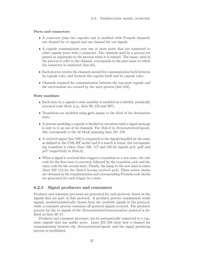
Ports and connectors� A connector joins two capsules and is modeled with Promela channels;one channel for in signals and one channel for out signals.� A capsule communicates over one or more ports that are connected toother capsule ports with a connector. The channels used by a process arepassed as arguments to the process when it is started. The name, used inthe process to refer to the channel, corresponds to the port name to whichthe connector is connected (line 64).� Each process creates the channels needed for communication both betweenits capsule roles, and between the capsule itself and its capsule roles.� Channels required for communication between the top-most capsule andthe environment are created by the init process (line 253).
State machines� Each state in a capsule’s state machine is modeled as a labeled, atomicallyexecuted code block (e.g., lines 99, 153 and 207).� Transitions are modeled using goto jumps to the label of the destinationstate.� A process modeling a capsule is blocked in execution until a signal messageis sent to it on one of its channels. For StateA in DemonstrationCapsule,this corresponds to the if block spanning lines 101–150.� A received signal (line 103) is compared to the signals handled by the stateas defined in the UML-RT model and if a match is found, the correspond-ing transition is taken (lines 106, 117 and 128 for signals goA, goB andgoC respectively in StateA).� When a signal is received that triggers a transition to a new state, the exitcode for the first state is executed, followed by the transition code and theentry code for the second state. Finally, the jump to the new label is taken(lines 105–114 for the StateA having received goA). These action chainsare obtained in the transformation and corresponding Promela code blocksare generated for each trigger in a state.
6.2.3 Signal producers and consumers
Producer and consumer processes are generated for each protocol, based on thesignals that are part of that protocol. A producer process continuously sendssignals, nondeterministically chosen from the available signals in the protocol,while a consumer process consumes all protocol signals received. The producerprocess for the in signals of the DemonstrationCommunication protocol is de-fined on lines 30–47.
Producer and consumer processes can be automatically connected to a top-most capsule that has public ports. Lines 253–258 show how a channel forcommunication between the DemonstrationCapsule and the signal producingprocess is established.
27
Chapter 6. Prototype system integrating RSARTE with Spin
6.2.4 Embedded Promela code
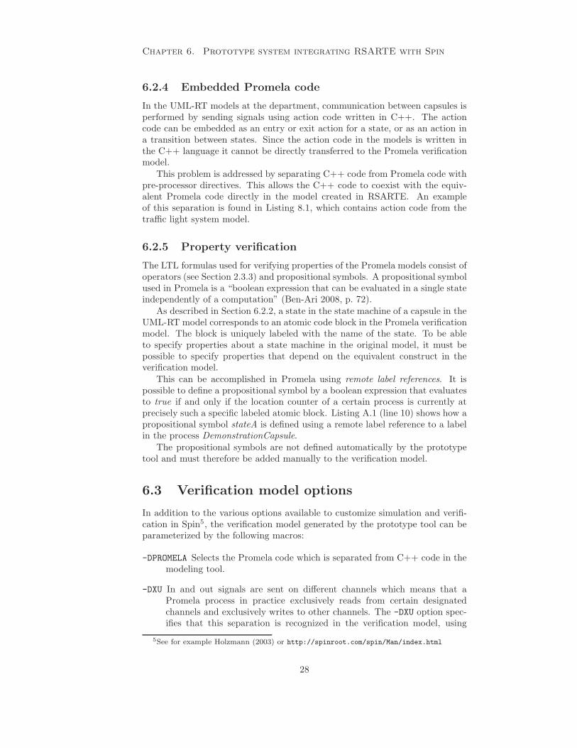
In the UML-RT models at the department, communication between capsules isperformed by sending signals using action code written in C++. The actioncode can be embedded as an entry or exit action for a state, or as an action ina transition between states. Since the action code in the models is written inthe C++ language it cannot be directly transferred to the Promela verificationmodel.
This problem is addressed by separating C++ code from Promela code withpre-processor directives. This allows the C++ code to coexist with the equiv-alent Promela code directly in the model created in RSARTE. An exampleof this separation is found in Listing 8.1, which contains action code from thetraffic light system model.
6.2.5 Property verification
The LTL formulas used for verifying properties of the Promela models consist ofoperators (see Section 2.3.3) and propositional symbols. A propositional symbolused in Promela is a “boolean expression that can be evaluated in a single stateindependently of a computation” (Ben-Ari 2008, p. 72).
As described in Section 6.2.2, a state in the state machine of a capsule in theUML-RT model corresponds to an atomic code block in the Promela verificationmodel. The block is uniquely labeled with the name of the state. To be ableto specify properties about a state machine in the original model, it must bepossible to specify properties that depend on the equivalent construct in theverification model.
This can be accomplished in Promela using remote label references. It ispossible to define a propositional symbol by a boolean expression that evaluatesto true if and only if the location counter of a certain process is currently atprecisely such a specific labeled atomic block. Listing A.1 (line 10) shows how apropositional symbol stateA is defined using a remote label reference to a labelin the process DemonstrationCapsule.
The propositional symbols are not defined automatically by the prototypetool and must therefore be added manually to the verification model.
6.3 Verification model options
In addition to the various options available to customize simulation and verifi-cation in Spin5, the verification model generated by the prototype tool can beparameterized by the following macros:
-DPROMELA Selects the Promela code which is separated from C++ code in themodeling tool.
-DXU In and out signals are sent on different channels which means that aPromela process in practice exclusively reads from certain designatedchannels and exclusively writes to other channels. The -DXU option spec-ifies that this separation is recognized in the verification model, using
5See for example Holzmann (2003) or http://spinroot.com/spin/Man/index.html
28

6.4. JET transformation structure
Promela’s channel assertions, which improves the performance of the ver-ification (Holzmann 2003, pp. 69-70). Using the option requires that thestandard Spin -DXUSAFE directive is used when compiling the verifier.
-DVERBOSE Specifies that each process should print the name of each state itenters in simulation runs, and that this information should be includedin generated message sequence diagrams (visual representations of errortrails).
-DCHANLEN=n Alters the channel length, used for all communication channels,from the default value of 1 to n.
6.4 JET transformation structure
The JET transformation project is hierarchically organized and the transforma-tion of the main model concepts, such as capsules and protocols, are sectionedinto different templates. This allows for a clear project structure and also fa-cilities the process of introducing modifications or extensions to the existingproject.
Figure 6.3: Structure of the JET transformation project.
Figure 6.3 illustrates the general structure of the transformation project.The emxTransform template is the main project template and includes othertemplate files, such as the genProtocols template which transforms model pro-tocols into Promela equivalents.
Appendix B shows an excerpt of the transformation project and containstwo template files: the main project template emxTransform (see Listing B.1),and the genStatemachine template (see Listing B.2).
29
CHAPTER 7
Property specification
The Promela model produced by the transformation is uninteresting, unless itcan be shown that the verification model does or does not satisfy properties thatpertain to the original UML-RT model. Correctness properties can be specifieddirectly in the Promela model using, e.g., assertions or labels, and they can alsobe generated from LTL formulas (Holzmann 2003, p. 75). In previous work (seeChapter 5), several approaches are presented for achieving verification of modelproperties.
Temporal properties can be classified in several ways; such as Lamport’s(1977) separation between safety and liveness properties,1 or Manna & Pnueli’s(1992) classification, which is based on the structure of LTL formulas. In thischapter we describe and categorize properties on the basis of how specificationand verification can be achieved in the prototype system.
7.1 Internally specified properties
The properties in the first category share the feature that they are not specifiedoutside2 the generated verification model, but are instead expressed as partof the structure of the Promela code. Since such properties are part of thePromela structure itself, they will be automatically included in any verificationof the model.
The objective of the prototype tool is to transform UML-RT capsules into aPromela representation, and this means that certain properties can be identifiedthat should hold for any UML-RT capsule, regardless of other constraints onits behavior. An example of such a property — one that can be considered anerror in any UML-RT capsule — is the presence of deadlocks.
A deadlock occurs in a situation “in which control is in the middle of theprogram, yet no part of the program is able to proceed.” (Manna & Pnueli 1992,
1Safety properties are those that specify that something will not happen whereas a livenessproperties specify that something must happen. (Lamport 1977)
2For example by using LTL formulas.
30
7.2. Externally specified properties
p. 309) The absence of deadlock is checked by default by Spin (Holzmann 2003,p, 75), which means that a standard verification run of a verification modelof communicating UML-RT capsules will automatically detect if a deadlocksituation between the capsules is possible. If, for example, a UML-RT modelcontains only two communicating capsules and they are both permitted to entera state where they wait for a signal from the other party, then the verificationmodel will be able to reach a point where no process can continue, causing adeadlock.
Other properties that are not quite as general as deadlock absence can beautomatically reflected in the verification model if particular states in the orig-inal model are given a role that can be recognized by Spin. An example of thisis the option, available both in vUML (Lilius & Porres Paltor 1999b, pp. 6–7)and VIP (Kamel & Leue 2000, p. 483) but not in the prototype tool3, to markcertain states with a progress4 label. The use of the label in the UML-RT modelcan be interpreted thus: entering the marked state signifies that some goal hasbeen accomplished or that useful work is performed by the state machine. Thisis a liveness property and if the model can exhibit cyclic behavior, wherein nostate machine performs useful work, then Spin is able to detect this possibility.
A third example of a correctness properties encoded automatically in thePromela model is discussed in Section 7.3.1.
7.2 Externally specified properties
The second category contains those properties that are specified outside thegenerated model (for example by writing LTL formulas) in contrast to the cor-rectness properties from the previous category. There are several possible waysof constructing properties that can be used to verify models. We highlight threepossible options discussed in previous work.
First, LTL formulas can be specified manually. LTL allows a wide varietyof properties to be captured in a notation with a very simple syntax (see Sec-tion 2.3.3). Still, formalizing even quite basic requirements in LTL can becomechallenging (Dwyer et al. 1999).
The second option is therefore to use a tool for guiding a user in specifyingproperties and aiding the user in writing correct syntax, but more importantlyin writing properties that capture the intended meaning of the requirement.This approach is used by the TABU tool (see Section 5.4).
The third option is to avoid direct use of LTL altogether and specify prop-erties in some visual notation. This approach is used by the Hugo tool (seeSection 5.2). The property can then be translated from visual notation to anLTL formula.
The prototype tool does not provide an option for external property speci-fication beyond manually written LTL formulas.
3The possibility of extending the prototype tool with such an option is discussed in Sec-tion 10.3.1.
4Both tools utilize the progress label (see Holzmann (2003, p. 459)) that already exists inthe Promela language.
31

Chapter 7. Property specification
7.3 Properties of primary interest
The example models in Chapter 8 will be used to demonstrate verification ofseveral properties from the two categories. The two properties that are of pri-mary interest to the department are related to the behavior of a single capsule.Informally stated, they are that,
1. a capsule’s state machine must, regardless of state, handle every signalthat it can receive; and
2. it must be detectable if leaving some state becomes impossible, once it hasbeen entered.
The LTL formula and mechanisms of the Promela model that enable verifi-cation of these two properties are described in the following sections.
7.3.1 Signal handling guarantee
Every state of a capsule’s state machine is associated with a set of transitionsleading to other states and a transition is taken when it is triggered. Thistriggering occurs when a signal, received at a port of the capsule, is deliveredto the behavior of the capsule. If a particular signal can arrive at a particularport and be delivered to the state machine when it is in a certain state whichhas no outgoing transition triggered by that signal, then this must be detectedin the verification model.
Verification of this property is achieved by taking advantage of Promela’sassertion statement in the verification model. Section 6.2.2 outlines how signalsand transition triggering is modeled in Promela. If no match for a receivedsignal is found then an assertion statement is intentionally violated.
The property becomes part of the verification model itself and is thereforeconsidered to be one of the properties that are internally specified.
7.3.2 Trap detection
It is possible that entering a particular state makes it impossible to leave thatstate. This can for example be caused by a lack of outgoing transitions. Ifcomplete signal handling has been guaranteed by the previous property, then atrap can still exist if the outgoing transitions from the state lead back to thesame state.
We let the propositional symbol s0 denote that the Promela process is ata point in the code corresponding to the capsule’s state machine being in thestate State 0. The property that State 0 is trapping is then captured by theLTL formula
�(s0 → �s0) (7.1)
Manna & Pnueli (1992, p. 192) refers to such a property (for the symbol p) as“once p, always p.”
To show that State 0 is trapping in all executions, the LTL formula suppliedto Spin is the negation of Property 7.1. This negated LTL formula formalizes vi-olations of the original property. In Spin syntax it is written ! [](s0 -> []s0).
If Spin is able to show a violation of the original property, then an error trailwill be produced that demonstrates how to leave State 0 once entered. If Spin
32

7.4. Limitations in property specification
is unable to show a violation of the original property then State 0 must in factbe trapping.
7.4 Limitations in property specification
Although LTL is expressive, there are limitations on the kinds of properties thatcan be stated in the language. One such limitation of LTL is that it does notallow quantification over paths, which means that it cannot be used to expressproperties that are related to the possible existence of paths. Huth & Ryan(2004, p. 184) gives examples of properties that consequently are impossible toexpress in LTL, such as:
“From any state it is possible to get to a restart state (i.e., thereis a path from all states to a state satisfying restart).”
Such properties may instead be expressed in other logics that allow quan-tification, such as CTL. CTL∗, which is a superset of both CTL and LTL,allows any formula in the two, and additionally permits formulas that can beexpressed in neither CTL nor LTL alone. See Huth & Ryan (2004, pp. 217-221)for examples and a comparison of the expressive powers of these logics.
33

CHAPTER 8
Model examples
This chapter presents a number of models created with RSARTE together withthe properties that have been used in verification. The models have been se-lected from tool training material (Rat 2003) in addition to Dijkstra’s well-known problem of the dining philosophers. A model illustrating the problemof verification model complexity is presented, as well as a model intended toillustrate verification of the two properties found to be of primary interest (seeSection 7.3).
8.1 A model of a traffic light system
The traffic light system model illustrates concepts of capsule communicationusing channels, as well as hierarchically constructed capsules (capsules contain-ing capsule roles). The model is implemented in RSARTE using capsules, statemachines and a communication protocol. We present three versions of the traf-fic light system to illustrate how properties can be proven and refuted, leadingto modifications of the design. The initial model is based on an exercise fromtraining material for RoseRT (Rat 2003) but differs in certain behavioral char-acteristics, as discussed later. The traffic light system example also illustrateshow design mistakes can be introduced in a system when the design is basedsolely on sequence diagrams.1
8.1.1 Model description
Two roads meet at an intersection and traffic through the intersection is guardedby traffic lights facing in the four directions of the compass. A central trafficlight controller sends directives to the traffic lights, signaling which states theyshould enter. The states of the controller correspond to its view of how thelights facing in the intersecting directions should behave.
1A sequence diagram is a graphical notation describing the behavior of a particular systemscenario.
34

8.1. A model of a traffic light system
The behavior of the controller is cyclic and the transitions between its controlstates are triggered by reception of timing events.
8.1.2 Properties
For an implementation of a traffic light system to be correct, the following listof properties should, at minimum, be fulfilled:
1. The signal handling guarantee property (see Section 7.3.1) must hold forall states in the model.
2. In an infinite run of the system, all traffic lights should display greeninfinitely often.
This liveness property specifies that the system should be starvation free,which is of interest since it proves that a car approaching the intersectionwill eventually be allowed to pass through it, regardless of when the cararrives or from which direction.
We let the propositional symbol northGreen denote that the north trafficlight is in state Green. The property for the north traffic light is expressedin LTL as:
�♦northGreen (8.1)
3. The system may never simultaneously signal green in such a way thattraffic can collide.
This safety property is an example of using mutual exclusion to controlaccess to a shared resource (the part of the intersection where traffic meets)and where a violation of the mutual exclusion property could have severeconsequences.
We let the propositional symbol northGreen denote that the north trafficlight is in state Green and analogously for the remaining three traffic lights.The mutual exclusion property for the traffic light system is expressed inLTL as:
� ¬( (northGreen ∨ southGreen) ∧ (eastGreen ∨ westGreen) ) (8.2)
8.1.3 First version
The first implementation is based directly on diagrams from the training mate-rial (Rat 2003). The state machines describing the behavior of both the trafficlights and the controller (see Figure 8.1(a) and Figure 8.2(a), respectively) aretransferred directly from this material.
Model elements
The model consists of the three capsules TrafficLight, Controller and Intersec-tion, and the protocol LightControl.
35

Chapter 8. Model examples
Listing 8.1: Initial transition effect code for the state machine of the Controllercapsule in the first version of the traffic light system.
1 #ifde f PROMELA2 nContro l out ! green ;3 sCont ro l out ! green ;4 eContro l out ! red ;5 wContro l out ! red ;6 #else7 myTiming . informIn (RTTimespec ( greenTime) ) ;8 nControl . green ( ) . send ( ) ;9 sContro l . green ( ) . send ( ) ;
10 eContro l . red ( ) . send ( ) ;11 wControl . red ( ) . send ( ) ;12 #endif
The behavior of the traffic light capsule is defined by its state machine (seeFigure 8.1(a)). The capsule also has a port control (see Figure 8.1(b)) throughwhich it receives signals from the controller. Each transition is triggered by aspecific signal from the controller capsule, e.g., the transition goGreen is trig-gered by the signal green. A traffic light always starts in its Red state.
The purpose of the Controller capsule is to cycle the traffic lights throughtheir different states according to a given pattern (see Figure 8.2(a)). The signalssent to the traffic lights, using action code in the transitions of the Controllercapsule state machine, are derived from the message sequence diagram fromthe training material (see Figure 8.3). Although the sequence diagram onlydescribes the signals sent to the north and west traffic lights, the action codeis extended to include also the south traffic light (being sent the same signal asnorth) and the east traffic light (being sent the same signal as west). The actioncode of the Controller ’s transition from its initial state to the state nsGreen isfound Listing 8.1.
The Intersection capsule contains all other capsules in the model and es-tablishes how the Controller capsule is connected to each TrafficLight capsule.The structure of the Intersection is visible in Figure 8.4.
The LightControl protocol defines the control signals green, yellow and redthat can be sent to the traffic lights.
8.1.4 Second version
The difference between the first model and the second lies in the state machineof the Controller capsule. Considering that a traffic light always enters the Redstate when it is started, it is unnecessary for the Controller to send the redsignal to the two traffic lights east and west, as Figure 8.3 suggests.
Modifications to model elements
The Controller capsule state machine is altered so that it does not send the redsignal to the east and west traffic lights in the initial transition. The consequence
36

8.1. A model of a traffic light system
is that lines 4, 5, 10 and 11 are removed from the transition effect code (seeListing 8.1) in second version.
8.1.5 Third version
The third version continues to build on the second version and introduces anacknowledgement scheme so that the Controller capsule also requires a responsefor each control signal sent to the traffic lights.
Modifications to model elements
An acknowledgment signal, ack, is added to the existing communication protocolLightControl and a message with this signal is sent by a TrafficLight in each ofthe transitions goGreen, goYellow and goRed.
The state machine of the Controller capsule is modified to require ack signalsto be received from the traffic lights for each control signal they are sent. Thisis accomplished by adding intermediary states whose outgoing transitions aretriggered on reception of the ack signal. The Controller is no longer allowed toenter its new control state until it has received ack messages from the correcttraffic lights.
The prototype tool does not support hierarchical states or transitions trig-gered by multiple signals, which explains why the new state machine of theController capsule (see Figure 8.5) becomes quite large.
37

Chapter 8. Model examples
(a) TrafficLight state machine
(b) TrafficLight structure diagram
Figure 8.1: State machine diagram and structure diagram of the traffic lightcapsule.
38
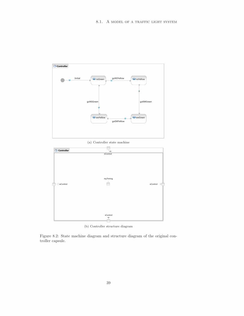
8.1. A model of a traffic light system
(a) Controller state machine
(b) Controller structure diagram
Figure 8.2: State machine diagram and structure diagram of the original con-troller capsule.
39

Chapter 8. Model examples
Figure 8.3: Sequence diagram of the traffic light system model illustrating in-teractions between the controller and two traffic lights. Figure from Rat (2003).
Figure 8.4: Structure diagram of the intersection capsule.
40

8.1
.A
model
of
atraffic
lig
ht
system
Figure 8.5: Modified state machine of the controller capsule.
41

Chapter 8. Model examples
Listing 8.2: Promela code for the stimulus producer process of the electroniclock model.
1 /* Producer proces s f o r the LockCommunication s i g n a l s */2 proctype LockCommunication prod (chan com) {3 #ifde f XU4 xs com ;5 #endif6 send :7 do8 : : true −> send one : com ! one ;9 : : true −> send two : com ! two ;
10 : : true −> s end que s t i on : com ! que s t i on ;11 : : true −> s end o the r : com ! other ;12 : : true −> s end lo ck : com ! l o ck ;13 od14 }
8.2 A model of an electronic lock
Training material for RoseRT (Rat 2003) describes a passive class2 that modelsthe behavior of a simple electronic combination lock. The model has a statemachine that changes state based on input in the form of characters. Enteringthe correct sequence of characters (1, 2) unlocks the lock, the character L locksthe lock and the character ? causes a help message to be printed.
8.2.1 Model description
The prototype tool does not support signals that carry a payload (such as acharacter), so we implement the model as a capsule that reacts to a set of in-put signals grouped into a protocol. This is a form of data type abstraction(Holzmann 2003, p. 236) where the entire input space (all characters) are re-duced to a set of signals. Such a change “can be justified if the correctnessproperties of a model do not depend on detailed values, but only on the chosenvalue ranges.”(Holzmann 2003, p. 236) The protocol signals are named one, two,question, lock and other.
Closing the model
The Lock capsule has a public port (see Figure 8.6(b)), which means that theverification model must be closed using a stimulus process to simulate non-deterministic behavior of its environment. The generated Promela code model-ing the signal producer is available in Listing 8.2.
2Unlike an active object, such as a capsule, a passive class does not have its own logicalthread of execution. While capsules are restricted to message passing for communication,passive classes communicate by procedure or function invocations.
42
8.2. A model of an electronic lock
8.2.2 Properties
A correct implementation of the lock model should satisfy the following prop-erties:
1. The signal guarantee property (see Section 7.3.1) must hold for all statesin the model.
2. The trap detection property (see Section 7.3.2) must be refuted for allstates in the model.
3. Ordering the lock to lock must always result in the lock eventually beinglocked, regardless of its current state.
We define propositional symbols as follows: snd lock denotes that theenvironment sends the signal lock, and locked denotes that the lock iscurrently in the state Locked. The property specifying the desired behavioris then expressed in LTL as:
�(snd lock → ♦locked) (8.3)
The property used by Spin to describe a violation of this behavior is thenegation of Property 8.3.
4. It should be possible to unlock the electronic lock when it is locked.
We define propositional symbols as follows: locked denotes that the lockcurrently is in state Locked, and unlocked denotes that that the lock isin state Unlocked. We demonstrate that this behavior is feasible by in-tentionally claiming that it is impossible, and using Spin to produce thecounterexample (Schafer et al. 2001). We make the intentionally incorrectclaim that: it is always the case that when the lock is locked, it will noteventually become unlocked.
This property is expressed in LTL as:
�(locked → ¬(♦unlocked)) (8.4)
If Spin can refute this claim, then a trail will be produced demonstratinghow to unlock the locked lock.
8.2.3 First version
Model elements
The model consists of the capsule Lock and the protocol LockCommunication.During the transformation process into Promela the verification model is ex-tended with the stimulus process whose task is to provide the lock with inputsignals.
The Lock capsule has a state machine consisting of three states (see Fig-ure 8.6(a)). The states signify the lock being either locked, in the state whenthe first correct signal of the unlocking sequence has been received, or unlocked.The Lock capsule receives input through the port lockCom (see Figure 8.6(b))and is always initialized in the Locked state.
The LockCommunication protocol defines the set of abstract signals that canbe sent to the electronic lock.
43

Chapter 8. Model examples
(a) Lock state machine
(b) Lock structure diagram
Figure 8.6: State machine diagram and structure diagram of the lock capsule.
8.2.4 Second version
The faulty model of the electronic lock is identical to the first model versionexcept for an intentional error introduced in the state machine of the Lockcapsule. The purpose of the second model is to demonstrate how such an errorin the model can be detected in the verification model.
Modifications to model elements
The Lock capsule’s state machine is modified (see Figure 8.7) by removing thetransition triggered by the signal other in the Unlocked state.
44

8.3. The dining philosophers
Figure 8.7: Modified state machine diagram of the lock capsule.
8.3 The dining philosophers
The problem of the dining philosophers (Dijkstra 1977) is a commonly usedillustration of how deadlocks can occur in the context of concurrently operatingcomputer systems. We model the problem using capsules, state machines andcommunication channels in RSARTE, and transform it into a verification modelin Promela.
p1
p2
p3p4
p5
Figure 8.8: Illustration of the problem of the dining philosophers, with fivephilosophers (labeled p1, . . . , p5) that sit around a table, sharing five chopsticks.
8.3.1 Problem scenario
Five philosophers each sit with a bowl of food around a circular table andspend their lives eating and thinking, without communicating with each other.Between each philosopher pair lies one chopstick (see Figure 8.8) and to beable to eat, a philosopher must use the two chopsticks that are shared with thephilosopher on either side.
45

Chapter 8. Model examples
One possible scheme for each philosopher to follow is described by Algo-rithm 1. However, the consequence of using this scheme is that an error sit-uation can occur if the philosophers time their actions such that they all pickup their left chopstick and then all turn their attention to the right chopstick,which is then forever unavailable. This can happen since the scheme introducesa situation that fulfills all of the four necessary conditions (Coffman, Elphick &Shoshani 1971) for a potential deadlock:
Mutual exclusion condition Every chopstick is shared by two philosophers.
Wait for condition After obtaining one chopstick the philosopher must ob-tain yet another one.
No preemption condition The philosophers do not communicate and cannotforcibly take chopsticks from each other.
Circular wait condition The philosophers are arranged around a table sothat each philosopher can hold a chopstick that is required by a neighbor.
Algorithm 1: Naıve procedure for acquiring and releasing resources inthe problem of the dining philosophers.
while true dobegin Thinking
Wait for some timeendbegin Hungry
Request(left chopstick)
Request(right chopstick)
begin EatingWait for some time
endRelease(left chopstick)
Release(right chopstick)end
Consequently, the problem of the dining philosophers is to establishing ascheme or protocol for the philosophers to follow that is both deadlock free andstarvation free (ensuring that all philosopher eventually are permitted to eat).There are several possible solutions to the problem.
One solution is to introduce a butler at the table that regulates how manyphilosophers can attempt to acquire chopsticks at the same time. The dead-lock situation can then be avoided by having the philosophers stand up (theycannot obtain chopsticks or eat standing up) and requiring the philosophers tobe granted permission from the butler before being seated at the table. Afterfinishing a meal, a philosopher will stand up again and notify the butler. Thebutler will not allow all of the philosophers to be seated at once; one chair isalways kept empty, which breaks the circular wait condition.
46
8.3. The dining philosophers
8.3.2 Model description
We present an RSARTE model of the problem based on the butler solution.The model has only four philosophers instead of the usual five, since a modelwith five philosophers produces a verification model that exhausts the resourcesof the test machine (see Section 3.1). The reduced number of philosophers doesnot affect the principle behind the solution.
8.3.3 Properties
The following properties should hold in a correct solution to the problem of thedining philosophers:
1. The signal handling guarantee property (see Section 7.3.1) must hold forall states in the model.
2. If a philosopher is eating, the philosopher’s two neighbors cannot also beeating.
We let the propositional symbol p1Eating denote that philosopher one iscurrently eating, and analogously for philosophers two and three. Thissafety property is expressed in LTL as:
� (p2Eating → ¬(p1Eating ∨ p3Eating)) (8.5)
The property used to describe a violation of the property to Spin is thenegation of Property 8.5.
3. If a philosopher is eating, then the chopsticks lying immediately to theleft and right must be in use.
We define propositional symbols as follows: c2TakenRight denotes thatchopstick two is acquired by the philosopher to its right and c2TakenRight-ReqLeft denotes that chopstick two is both acquired by the philosopher toits right and requested by the philosopher to its left (see Figure 8.9 andFigure 8.12(a)).
The property is expressed in LTL as:
� (p2Eating → ((c1TakenLeft ∨ c1TakenLeftReqRight)
∧ (c2TakenRight ∨ c2TakenRightReqLeft)))(8.6)
The property used to describe a violation of the property to Spin is thenegation of Property 8.6.
4. In an infinite run of the model, a philosopher must be allowed to eatinfinitely often. This property specifies that model is starvation free andmust hold for all philosophers.3
The property is expressed in LTL as:
� ♦ p2Eating (8.7)
The property used to describe a violation of the property to Spin is thenegation of Property 8.7.
3The property does not hold for the model, as will be demonstrated and explained inSection 9.3.
47

Chapter 8. Model examples
8.3.4 Model implementation
Model elements
The model consists of the four capsules Table, Butler, Philosopher, and Chop-stick ; and the protocol ResourceAllocation.
The Table capsule has no purpose other than to contain capsule roles and todefine the relationships and communication channels between the capsule roles(see Figure 8.9).
Figure 8.9: Structure diagram of the table capsule.
The behavior of a philosopher is defined by the state machine (see Fig-ure 8.10(a)) of the Philosopher capsule. The primary tasks for a philosopherare to think and eat, captured by the states Thinking or Eating, respectively.Before a philosopher can eat it must first be allowed a place at the table andthen acquire two chopsticks. The Philosopher capsule has three communicationports: butler, through which requests for a seat at the table is made and granted;and left and right, through which the philosopher requests and is granted accessto the chopsticks to the left and right (see Figure 8.10(b)).
The butler determines when a philosopher is allowed a seat. This behavioris defined in the Butler capsule’s state machine, see Figure 8.11(a). Commu-nication with the philosophers is conducted through four4 ports, one for eachphilosopher (see Figure 8.11(b)).
A chopstick can be acquired or returned by a philosopher sitting either tothe left or to the right of the chopstick (see Figure 8.12(a)). The signal togrant the philosopher on the left access to a chopstick is sent in the transitionleftReq (because the chopstick was available and then requested by left) and thetransition rightRet (because the chopstick was taken by right, requested by left
4The prototype tool does not support replicated ports, which are possible to use inUML-RT.
48

8.4. A model with intentional errors
and then returned by right), and vice versa for the philosopher on the right.5
The ResourceAllocation protocol defines the different signals of the model,used for either requesting or returning a resource and notifying if a requestis granted. The signals are req, ret and grant, respectively. The protocol isboth used for communication between a philosopher and a chopstick, and forcommunication between a philosopher and the butler.
8.4 A model with intentional errors
The model described in this section is indented to demonstrate the results ofverifying only the two properties that are of primary interest to the department(see Section 7.3). The model is therefore very simple and contains two deliberateerrors of the types that must be found during model verification. The Promelamodel produced for this model is available in Appendix A.
8.4.1 Model description and properties
The model is verified with respect to the following properties:
1. The signal handling guarantee property (see Section 7.3.1) must hold forall states in the model.
2. The trap detection property (see Section 7.3.2) must be refuted for allstates in the model.
Model elements
The model consists of a single capsule DemonstrationCapsule (see Figure 8.13)and the protocol DemonstrationCommunication. In the transformation processinto Promela, the model is extended with a stimulus process whose task it isto close the verification model by simulating an indeterministic environment ofthe DemonstrationCapsule.
The demonstration capsule’s behavior is defined by a state machine contain-ing three states: StateA, StateB and StateC. The DemonstrationCommunicationprotocol defines the signals that can be sent to the demonstration capsule. Eachsignal is intended to trigger a transition being taken to the state whose namecorresponds to the name of the signal. The signals of the protocol are: goA,goB and goC.
StateA and StateC both handle all signals correctly, triggering transitionsto the other states upon reception of the signals, whereas StateB contains twoerrors. The transition named goToA, triggered by the signal goA, is a self-transition leading back to StateB. The transition named goToC is missing com-pletely from StateB.
The consequence is that StateB is both a trapping state, in violation ofproperty 2, and fails to handle all signals, in violation of property 1.
5It is also possible to sent the signals directly in the entry action of the two states TakenLeft
and TakenRight.
49

Chapter 8. Model examples
8.5 A complexity experiment
While it is beyond the scope of this thesis to cope with models of the size orcomplexity as of those used at the department, it is nonetheless of interest togive an idea of how fast a verification model can grow. The complexity of theverification model depends on the complexity and modeling constructs used inthe original model. It is necessary to control the complexity of the verificationmodel to avoid exhausting memory resources or exceeding the time availablefor verification. Holzmann (2003, p. 119) writes “the worst-case computationalexpense of verifying any type of correctness property with a model checkerincreases with the number of reachable system states R of a model.”
A UML-RT capsule typically has many public ports sending and receivingmany possible signals. This communication diversity introduces complexity inthe verification model attributable to three factors:
1. The number of Promela channels in the verification model, which corre-sponds to the number of ports in the original model.
2. The number of different message types in the verification model, whichcorresponds the number of different signals of the protocols in the originalmodel.
3. The length of the Promela channels. This parameter must be fixed inorder to close the verification model.
The complexity introduced by a set of message channels in a verificationmodel can be understood by the number of states that such a set of objects canbe in. Holzmann (2003, pp. 119-120) gives the number of states RQ in terms ofthe number of channels q, the number of different messages m and the lengthof the channel s:
RQ =
(
s∑
i=0
mi
)q
(8.8)
We illustrate the complexity introduced by communication channels by mod-eling a UML-RT capsule with one state and one port that receives messages ofa protocol with one signal. All signals from all ports are handled by triggeringa transition back to the same single state.
The effects in practice of increasing the number of possible signal are com-pared with the effect of increasing the number of ports receiving those signals.Those are the parameters in Equation 8.8 that are derived directly from theoriginal UML-RT model. The length of a channel is a restriction in Promelawhich does originate from the UML-RT model, and is therefore fixed in all mod-els. The comparison is made by performing a verification of the signal handlingguarantee property (see Section 7.3.1) for each model version and obtaining thenumber of global system states stored in the state space for each verificationrun.
50

8.5. A complexity experiment
(a) Philosopher state machine
(b) Philosopher structure diagram
Figure 8.10: State machine diagram and structure diagram of the philosophercapsule.
51

Chapter 8. Model examples
(a) Butler state machine
(b) Butler structure diagram
Figure 8.11: State machine diagram and structure diagram of the butler capsule.
52

8.5. A complexity experiment
(a) Chopstick state machine
(b) Chopstick structure diagram
Figure 8.12: State machine diagram and structure diagram of the chopstickcapsule.
53

Chapter 8. Model examples
(a) Demonstration capsule state machine
(b) Demonstration capsule structure diagram
Figure 8.13: State machine diagram and structure diagram of the demonstrationcapsule.
54
CHAPTER 9
Results
This chapter presents verification results for the sample models described inChapter 8.
9.1 Traffic light system
The properties listed in Section 8.1.2 are verified one by one for each version ofthe model. In those cases where a property is proven not to hold, any remainingproperties for that model version are excluded from verification. In some casesthe number of errors for a particular property and model version exceeds one.This is due to an iterative search used to find the shortest path to the error.
9.1.1 First version
Property 1 (Signal handling guarantee)
The verification results in errors (see Listing 9.1), demonstrating that there isat least one state in the model which does not handle every possible input sig-nal. The generated error trail demonstrates how an assertion due to unhandledsignals can be violated and can be illustrated visually using a message sequencediagram (see Figure 9.1).
We can see that as the controller capsule makes its initial transition (lines27–35) it sends signals to all four traffic lights (lines 31–34). The east trafficlight receives the red signal (line 39) even though it is already in the Red state(line 16). The red signal is not handled in the Red state (see Section 8.1.3)which causes an assertion violation (line 41).
55

Chapter 9. Results
Listing 9.1: Verification results for property 1 (signal handling guarantee) forthe first version of the traffic light system model.
1 (Spin Version 5.1.7 -- 23 December 2008)
2 + Partial Order Reduction
3
4 Full statespace search for:
5 never claim - (none specified )
6 assertion violations +
7 cycle checks - (disabled by -DSAFETY)
8 invalid end states +
9
10 State -vector 76 byte , depth reached 32, errors: 2
11 15 states , stored
12 8 states , matched
13 23 transitions (= stored+matched )
14 26 atomic steps
15 hash conflicts : 0 (resolved )
16
17 2.501 memory usage (Mbyte)
0 0::init:1 1:Intersection
2 2:Controller
3 3:TrafficLight
4 4:TrafficLight
5 5:TrafficLight
6 6:TrafficLight
9 _initial
11 Red
12 TrafficLight: entering Red state
14 _initial
16 Red
17 TrafficLight: entering Red state
19 _initial
21 Red
22 TrafficLight: entering Red state
24 _initial
26 Red
27 TrafficLight: entering Red state
29 _initial
31 nControl_out!green
32 sControl_out!green
33 eControl_out!red
34 wControl_out!red
35 nsGreen
36 _initial
38 State1
39 control?red
41 Unhandled signal red in Red
Figure 9.1: Error scenario for property 1 (signal handling guarantee) for thefirst version of the traffic light system model.
56

9.1. Traffic light system
Listing 9.2: Verification results for property 1 (signal handling guarantee) forthe second version of the traffic light system model.
1 (Spin Version 5.1.7 -- 23 December 2008)
2 + Partial Order Reduction
3
4 Full statespace search for:
5 never claim - (none specified )
6 assertion violations +
7 cycle checks - (disabled by -DSAFETY )
8 invalid end states +
9
10 State -vector 76 byte , depth reached 202, errors: 0
11 325 states , stored
12 493 states , matched
13 818 transitions (= stored+matched)
14 945 atomic steps
15 hash conflicts : 0 (resolved )
16
17 2.501 memory usage (Mbyte)
9.1.2 Second version
Property 1 (signal handling guarantee)
The verification produces no errors (see Listing 9.2), proving that assertionviolations due to unhandled signals cannot occur.
Property 2 (recurrence)
The property is verified for all four traffic lights in the model and does notproduce any errors, proving that all traffic lights exhibit a cyclic behavior andenter the Green state infinitely often in an infinite run of the model. Theproperty also holds for the Yellow state and Red state for each traffic light.
Only the result from the verification of the north traffic light’s green stateis presented (see Listing 9.3). The remaining eleven out of twelve verificationruns (four traffic lights and three states) produce near-identical results and areomitted.
Property 3 (mutual exclusion)
The verification produces errors (see Listing 9.4), proving that the mutual exclu-sion property does not hold for the four traffic lights guarding the intersection.It is therefore possible that two traffic lights guarding intersecting roads can si-multaneously be in their respective Green states, which could lead to collisionsin a real system.
The visual representation (see Figure 9.2) of the error trail illustrates amessage sequence by which the property claim can be refuted. The root causeof the error is that the controller capsule is allowed to switch between controlstates without first establishing that its previously sent messages have beenreceived by the traffic lights.
57

Chapter 9. Results
Listing 9.3: Verification results for property 2 (recurrence) for the second versionof the traffic light system model.
1 (Spin Version 5.1.7 -- 23 December 2008)
2 + Partial Order Reduction
3
4 Full statespace search for:
5 never claim +
6 assertion violations + (if within scope of claim)
7 acceptance cycles + (fairness disabled )
8 invalid end states - (disabled by never claim)
9
10 State -vector 80 byte , depth reached 288, errors: 0
11 615 states , stored (905 visited )
12 2054 states , matched
13 2959 transitions (= visited+matched )
14 3157 atomic steps
15 hash conflicts : 12 (resolved )
16
17 2.501 memory usage (Mbyte)
Listing 9.4: Verification results for property 3 (mutual exclusion) for the secondversion of the traffic light system model.
1 (Spin Version 5.1.7 -- 23 December 2008)
2 + Partial Order Reduction
3
4 Full statespace search for:
5 never claim +
6 assertion violations + (if within scope of claim)
7 acceptance cycles + (fairness disabled )
8 invalid end states - (disabled by never claim)
9
10 State -vector 80 byte , depth reached 157, errors: 18
11 318 states , stored (324 visited )
12 671 states , matched
13 995 transitions (= visited+matched )
14 1191 atomic steps
15 hash conflicts : 0 (resolved )
16
17 2.501 memory usage (Mbyte)
58

9.1. Traffic light system
Listing 9.5: Verification results for property 1 (signal handling guarantee) forthe third version of the traffic light system model.
1 (Spin Version 5.1.7 -- 23 December 2008)
2 + Partial Order Reduction
3
4 Full statespace search for:
5 never claim - (none specified )
6 assertion violations +
7 cycle checks - (disabled by -DSAFETY )
8 invalid end states +
9
10 State -vector 104 byte , depth reached 155, errors: 0
11 283 states , stored
12 421 states , matched
13 704 transitions (= stored+matched)
14 1063 atomic steps
15 hash conflicts : 0 (resolved )
16
17 2.501 memory usage (Mbyte)
Figure 9.2 shows a situation in which the north, east and west traffic lightssimultaneously are in the Green state. The chain of events leading to thissituation is the following:
1. The north traffic light is in state Red (line 77), the east traffic light is instate green (line 72) and the west traffic light is in state Green (line 82).
2. The controller transitions from the state ewGreen to the state ewYellow(lines 68–88) and sends the signal yellow to both the east and west trafficlights (lines 86–87).
3. Those signals have not yet been received when the controller transitions toits next state and sends the signal Green to the north traffic light (line 91).
4. The north traffic light receives the green signal (line 92) and enters itsGreen state (line 95).
This causes green lights in intersecting directions, which is a violation of themutual exclusion property.
9.1.3 Third version
Property 1 (signal handling guarantee)
The verification produces no errors (see Listing 9.5), proving that assertionviolations due to unhandled signals cannot occur. This is the same result as forthe first and second versions of the traffic light system.
Property 2 (recurrence)
The property is verified for all four traffic lights in the model and does notproduce any errors. This is the same result as for the second version of the
59

Chapter 9. Results
49 nControl_out!yellow
50 sControl_out!yellow
51 nsYellow
52 control?yellow
54 TrafficLight: exiting Green state
55 Yellow
56 TrafficLight: entering Yellow state
57 control?yellow
59 TrafficLight: exiting Green state
60 Yellow
61 TrafficLight: entering Yellow state
64 nControl_out!red
65 sControl_out!red
66 eControl_out!green
67 wControl_out!green
68 ewGreen
69 control?green
71 TrafficLight: exiting Red state
72 Green
73 TrafficLight: entering Green state
74 control?red
76 TrafficLight: exiting Yellow state
77 Red
78 TrafficLight: entering Red state
79 control?green
81 TrafficLight: exiting Red state
82 Green
83 TrafficLight: entering Green state
86 eControl_out!yellow
87 wControl_out!yellow
88 ewYellow
91 nControl_out!green
92 control?green
94 TrafficLight: exiting Red state
95 Green
96 TrafficLight: entering Green state
97 control?red
99 TrafficLight: exiting Yellow state
Figure 9.2: Error scenario for property 3 (mutual exclusion) for the secondversion of the traffic light system model.
60

9.2. Electronic lock
Listing 9.6: Verification results for property 2 (recurrence) for the third versionof the traffic light system model.
1 (Spin Version 5.1.7 -- 23 December 2008)
2 + Partial Order Reduction
3
4 Full statespace search for:
5 never claim +
6 assertion violations + (if within scope of claim)
7 acceptance cycles + (fairness disabled )
8 invalid end states - (disabled by never claim)
9
10 State -vector 108 byte , depth reached 214, errors: 0
11 527 states , stored (771 visited)
12 1784 states , matched
13 2555 transitions (= visited +matched)
14 3574 atomic steps
15 hash conflicts : 0 (resolved )
16
17 2.501 memory usage (Mbyte)
traffic light system. Listing 9.6 presents the result from the verification run ofthe north traffic light’s green state.
Property 3 (mutual exclusion)
The verification produces no error (see Listing 9.7), proving that the mutualexclusion property holds for the traffic system. The traffic lights for the in-tersecting roads do not enter their Green states in such a way that traffic cancollide.
9.2 Electronic lock
The properties listed in Section 8.2.2 are verified one by one for each version ofthe model. In those cases where a property is proven not to hold, any remainingproperties for that model version are excluded from verification. In some casesthe number of errors for a particular property and model version exceeds one.This is due to an iterative search used to find the shortest path to the error.
9.2.1 First version
Property 1 (signal handling guarantee)
The verification produces no error (see Listing 9.8), proving that assertion vio-lations due to unhandled signals cannot occur.
Property 2 (trap detection)
The property is verified for all states in the model and produces counterexamplesin every case. This demonstrates that no state in the model is a trapping state.
61

Chapter 9. Results
Listing 9.7: Verification results for property 3 (mutual exclusion) for the thirdversion of the traffic light system model.
1 (Spin Version 5.1.7 -- 23 December 2008)
2 + Partial Order Reduction
3
4 Full statespace search for:
5 never claim +
6 assertion violations + (if within scope of claim)
7 acceptance cycles + (fairness disabled )
8 invalid end states - (disabled by never claim)
9
10 State -vector 108 byte , depth reached 214, errors: 0
11 283 states , stored
12 421 states , matched
13 704 transitions (= stored+matched )
14 1063 atomic steps
15 hash conflicts : 0 (resolved )
16
17 2.501 memory usage (Mbyte)
Listing 9.8: Verification results for property 1 (signal handling guarantee) forthe first version of the electronic lock model.
1 (Spin Version 5.1.7 -- 23 December 2008)
2 + Partial Order Reduction
3
4 Full statespace search for:
5 never claim - (none specified )
6 assertion violations +
7 cycle checks - (disabled by -DSAFETY)
8 invalid end states +
9
10 State -vector 28 byte , depth reached 169, errors: 0
11 424 states , stored
12 245 states , matched
13 669 transitions (= stored+matched )
14 302 atomic steps
15 hash conflicts : 0 (resolved )
16
17 2.501 memory usage (Mbyte)
62

9.2. Electronic lock
Listing 9.9: Verification results for property 2 (trap detection) for the firstversion of the electronic lock model.
1 (Spin Version 5.1.7 -- 23 December 2008)
2 + Partial Order Reduction
3
4 Full statespace search for:
5 never claim +
6 assertion violations + (if within scope of claim)
7 acceptance cycles + (fairness disabled )
8 invalid end states - (disabled by never claim)
9
10 State -vector 32 byte , depth reached 20, errors: 2
11 125 states , stored
12 216 states , matched
13 341 transitions (= stored+matched)
14 78 atomic steps
15 hash conflicts : 0 (resolved )
16
17 2.501 memory usage (Mbyte)
0 0::init:1 1:LockCommunication_prod
2 2:Lock
4 _initial
6 Locked
7 Lock is locked.
9 com!one
10 lockCom?one
12 FirstCorrect
14 com!one
Figure 9.3: Error scenario for property 2 (trap detection) for the first version ofthe electronic lock model.
We present only the result for state Locked (see Listing 9.9) since the results forthe other states are near-identical.
The visual representation of the error trail (see Figure 9.3) produced bySpin shows a counterexample to the claim that state Locked is trapping. In thecounterexample, we can see that the lock is in state Locked (line 6). This statecan be exited by following the transition triggered on reception of the signal one(line 10), leading into state FirstCorrect.
Property 3 (locking the lock)
The verification produces no error (see Listing 9.10). This proves that if theenvironment sends the signal lock, the lock will eventually become locked.
63

Chapter 9. Results
Listing 9.10: Verification results for property 3 (the lock can be locked) for thefirst version of the electronic lock model.
1 (Spin Version 5.1.7 -- 23 December 2008)
2 + Partial Order Reduction
3
4 Full statespace search for:
5 never claim +
6 assertion violations + (if within scope of claim)
7 acceptance cycles + (fairness disabled )
8 invalid end states - (disabled by never claim)
9
10 State -vector 32 byte , depth reached 296, errors: 0
11 484 states , stored (531 visited )
12 472 states , matched
13 1003 transitions (= visited+matched )
14 464 atomic steps
15 hash conflicts : 0 (resolved )
16
17 2.501 memory usage (Mbyte)
Property 4 (unlocking the lock)
The verification produces errors (see Listing 9.11) and a trail, refuting the claimthat a locked lock is impossible to unlock.
The message sequence diagram (see Figure 9.4) illustrating the error traildemonstrates a counterexample to the claim. As expected, the lock can indeedbe unlocked (line 24) if the environment provides the correct sequence of inputsignals, i.e., by sending signal one (line 9), followed by signal two (line 14).
9.2.2 Second version
Property 1 (signal handling guarantee)
The verification produces errors (see Listing 9.12) demonstrating that there isat least one state in the model that does not handle all types of input signals.
The message sequence diagram (see Figure 9.5) illustrating the error traildemonstrates a signal sequence that causes an assertion violation, due to anunhandled signal. The violation occurs in state Unlocked (line 23) on receptionof the signal other, sent by the environment (line 20).
9.3 Dining philosophers
The properties listed in Section 8.3.3 are verified one by one for the model ofthe dining philosophers.
Property 1 (signal handling guarantee)
The verification produces no errors (see Listing 9.13), proving that no assertionviolations due to unhandled signals can occur.
64

9.3. Dining philosophers
Listing 9.11: Verification results for property 4 (the lock cannot be unlocked)for the first version of the electronic lock model.
1 (Spin Version 5.1.7 -- 23 December 2008)
2 + Partial Order Reduction
3
4 Full statespace search for:
5 never claim +
6 assertion violations + (if within scope of claim)
7 acceptance cycles + (fairness disabled )
8 invalid end states - (disabled by never claim)
9
10 State -vector 32 byte , depth reached 41, errors: 4
11 485 states , stored
12 818 states , matched
13 1303 transitions (= stored+matched)
14 574 atomic steps
15 hash conflicts : 0 (resolved )
16
17 2.501 memory usage (Mbyte)
0 0::init:1 1:LockCommunication_prod
2 2:Lock
4 _initial
6 Locked
7 Lock is locked.
9 com!one
10 lockCom?one
12 FirstCorrect
14 com!two
15 lockCom?two
17 Unlocked
18 Lock is unlocked!
20 com!one
Figure 9.4: Error scenario for property 4 (the lock cannot be unlocked) for thefirst version of the electronic lock model.
65

Chapter 9. Results
Listing 9.12: Verification results for property 1 (signal handling guarantee) forthe second version of the electronic lock model.
1 (Spin Version 5.1.7 -- 23 December 2008)
2 + Partial Order Reduction
3
4 Full statespace search for:
5 never claim - (none specified )
6 assertion violations +
7 cycle checks - (disabled by -DSAFETY)
8 invalid end states +
9
10 State -vector 28 byte , depth reached 58, errors: 11
11 389 states , stored
12 805 states , matched
13 1194 transitions (= stored+matched )
14 1013 atomic steps
15 hash conflicts : 0 (resolved )
16
17 2.501 memory usage (Mbyte)
0 0::init:1 1:LockCommunication_prod
2 2:Lock
4 _initial
6 Locked
7 Lock is locked.
9 com!one
10 lockCom?one
12 FirstCorrect
14 com!two
15 lockCom?two
17 Unlocked
18 Lock is unlocked!
20 com!other
21 lockCom?other
23 Unhandled signal other in Unlocked
Figure 9.5: Error scenario for property 1 (signal handling guarantee) for thesecond version of the electronic lock model.
66

9.3. Dining philosophers
Listing 9.13: Verification results for property 1 (signal handling guarantee) forthe dining philosophers model.
1 (Spin Version 5.1.7 -- 23 December 2008)
2 + Partial Order Reduction
3
4 Full statespace search for:
5 never claim - (none specified )
6 assertion violations +
7 cycle checks - (disabled by -DSAFETY )
8 invalid end states +
9
10 State -vector 248 byte , depth reached 480492 , errors: 0
11 1493090 states , stored
12 6997300 states , matched
13 8490390 transitions (= stored+matched)
14 11225119 atomic steps
15 hash conflicts : 5920646 (resolved )
16
17 394.554 memory usage (Mbyte)
Property 2 (simultaneous eating)
The property is verified for all four philosophers in the model and does notproduce errors in any case. This proves, for all philosophers, that if a philosopheris eating then the two neighboring philosophers are not eating (since they sharechopsticks). We present only the verification result for philosopher one (seeListing 9.14) since the results for the other philosophers are near-identical.
Property 3 (chopstick usage)
The property is verified for all four philosophers in the model and does not pro-duce errors in any case. This proves, for all philosophers, that if a philosopheris eating, it uses the chopsticks on both sides. We present only the verifica-tion result for philosopher one (see Listing 9.15) since the results for the otherphilosophers are near-identical.
Property 4 (recurrence)
Verification of the property produces a counterexample for each philosopherin the model. Listing 9.16 shows the verification result for philosopher oneand contains an error, which proves that there exists an infinite execution ofthe model in which it is not the case that philosopher one is allowed to eatinfinitely many times. The reason for this is that the Butler process has aseparate communication channel for each Philosopher and there is no facility inthe verification model to force the Butler to choose fairly between Philosophers.
67

Chapter 9. Results
Listing 9.14: Verification results for property 2 (simultaneous eating) for thedining philosophers model.
1 (Spin Version 5.1.7 -- 23 December 2008)
2 + Partial Order Reduction
3
4 Full statespace search for:
5 never claim +
6 assertion violations + (if within scope of claim)
7 acceptance cycles + (fairness disabled )
8 invalid end states - (disabled by never claim)
9
10 State -vector 252 byte , depth reached 657968 , errors: 0
11 1493090 states , stored
12 6997300 states , matched
13 8490390 transitions (= stored+matched )
14 11225119 atomic steps
15 hash conflicts : 5929190 (resolved )
16
17 Stats on memory usage (in Megabytes ):
18 381.611 equivalent memory usage for states
(stored *(State -vector + overhead ))
19 325.017 actual memory usage for states (compression :
85.17%)
20 state -vector as stored = 212 byte + 16 byte
overhead
21 2.000 memory used for hash table (-w19)
22 21.362 memory used for DFS stack (-m700000)
23 348.265 total actual memory usage
68

9.3. Dining philosophers
Listing 9.15: Verification results for property 3 (chopstick usage) for the diningphilosophers model.
1 (Spin Version 5.1.7 -- 23 December 2008)
2 + Partial Order Reduction
3
4 Full statespace search for:
5 never claim +
6 assertion violations + (if within scope of claim)
7 acceptance cycles + (fairness disabled )
8 invalid end states - (disabled by never claim)
9
10 State -vector 252 byte , depth reached 657968 , errors: 0
11 1493090 states , stored
12 6997300 states , matched
13 8490390 transitions (= stored+matched)
14 11225119 atomic steps
15 hash conflicts : 5929190 (resolved )
16
17 Stats on memory usage (in Megabytes ):
18 381.611 equivalent memory usage for states
(stored *( State -vector + overhead ))
19 325.016 actual memory usage for states (compression :
85.17%)
20 state -vector as stored = 212 byte + 16 byte
overhead
21 2.000 memory used for hash table (-w19)
22 21.362 memory used for DFS stack (-m700000 )
23 348.265 total actual memory usage
Listing 9.16: Verification results for property 4 (recurrence) for the diningphilosophers model.
1 (Spin Version 5.1.7 -- 23 December 2008)
2 + Partial Order Reduction
3
4 Full statespace search for:
5 never claim +
6 assertion violations + (if within scope of claim)
7 acceptance cycles + (fairness disabled )
8 invalid end states - (disabled by never claim)
9
10 State -vector 252 byte , depth reached 129, errors: 1
11 26596 states , stored (39893 visited)
12 199034 states , matched
13 238927 transitions (= visited +matched)
14 359188 atomic steps
15 hash conflicts : 2200 (resolved )
16
17 29.319 memory usage (Mbyte)
69

Chapter 9. Results
Listing 9.17: Verification results for property 1 (signal handling guarantee) forthe demonstration model.
1 (Spin Version 5.1.7 -- 23 December 2008)
2 + Partial Order Reduction
3
4 Full statespace search for:
5 never claim - (none specified )
6 assertion violations +
7 cycle checks - (disabled by -DSAFETY)
8 invalid end states +
9
10 State -vector 28 byte , depth reached 38, errors: 7
11 79 states , stored
12 89 states , matched
13 168 transitions (= stored+matched )
14 138 atomic steps
15 hash conflicts : 0 (resolved )
16
17 2.501 memory usage (Mbyte)
9.4 Model with intentional errors
The properties listed in Section 8.4.1 are verified for the model. In some casesthe number of errors for a particular property exceeds one. This is due to aniterative search used to find the shortest path to the error.
Property 1 (signal handling guarantee)
The verification produces errors (see Listing 9.17) which proves that there is atleast one state in the model that does not handle all input signals.
The message sequence chart (see Figure 9.6) generated from the error traildemonstrates how an assertion can be violated as a result of a signal not beinghandled. The figure illustrates that when the capsule is in StateB (line 11) andthe environment sends the signal goC (line 13) which is received while still inStateB (line 14), the result is an assertion violation (line 16).
Property 2 (trap detection)
The verification is performed for every state in the model and produces a coun-terexample in all cases except for StateB, proving that StateB is the only trap-ping state in the model. The verification result in Listing 9.18 shows that Spincannot refute the claim that specifies that stateB is a trapping state.
9.5 Complexity experiment
The results of the complexity experiment for comparing the state space effectsof increased number of ports and signals are presented in Figure 9.7. We seethat the behavior predicted by Equation 8.8 is exhibited by the verified models.
70

9.5. Complexity experiment
0 0::init:1 1:DemonstrationCommunication_prod
2 2:DemonstrationCapsule
4 _initial
6 StateA
8 com!goB
9 demoCom?goB
11 StateB
13 com!goC
14 demoCom?goC
16 Unhandled signal goC in StateB
Figure 9.6: Error scenario of property 1 (signal handling guarantee) for thedemonstration model.
Listing 9.18: Verification results for property 2 (trap detection) for the demon-stration model.
1 (Spin Version 5.1.7 -- 23 December 2008)
2 + Partial Order Reduction
3
4 Full statespace search for:
5 never claim +
6 assertion violations - (disabled by -A flag )
7 acceptance cycles + (fairness disabled )
8 invalid end states - (disabled by never claim)
9
10 State -vector 32 byte , depth reached 89, errors: 0
11 139 states , stored
12 121 states , matched
13 260 transitions (= stored+matched)
14 137 atomic steps
15 hash conflicts : 0 (resolved )
16
17 2.501 memory usage (Mbyte)
71

Chapter 9. Results
The number of stored states increases exponentially when the number of portsis increased, but more slowly when the number of signals is increased.
We can also observe a plateau effect in Figure 9.7 which is due to insufficientmemory resources. For larger values for the number of states or ports, thememory required to perform the verification exceeds the available memory ofthe test machine (see Section 3.1).
1 2 3 4 5 6 7 8 9 10
12
34
56
78
910
100
101
102
103
104
105
106
107
108
SignalsPorts
Sto
red
stat
es
Figure 9.7: Number of stored states used for verifying the signal handling guar-antee property (see Section 7.3.1) depending on the number of ports and signalsused. Note that the plateau effect is due to insufficient memory resources whichresults in incomplete verification.
72

CHAPTER 10
Conclusions
This chapter presents answers the questions posed in Section 1.2 and a discussionon the verification approach, the prototype tool and their limitations.
10.1 Answers to questions
Question 1
What methods and tools for formal verification of software models are availablein the academic, industrial or open source communities?
This question is addressed by decomposition into sub-questions.
Sub-question 1a
What approach could be used as a basis for verification of models developed atthe department?
Previous work for verifying properties of UML state machines and a visualformalism similar to UML-RT has been found in the literature. The reviewedtools all use a transformational approach, in the sense that UML models, oftenconsisting of a subset of the available model constructs, are transformed to theinput language of a general model checker. Properties of the transformed modelare then verified with the model checker and the results of the verification areinterpreted in the context of the original model.
The model checkers used as back-ends for the verification include Spin, SMVand RuleBase. Spin is a dominating tool in the domain of software modelchecking. A majority of the previous work transforms the original model into averification model specified in Promela, the input language of Spin, and this isalso the case in our work.
73

Chapter 10. Conclusions
Sub-question 1b
Are there existing tools for formal verification that can be directly used to verifyproperties of models in the development environment at the department? Ifthis is not the case, are there existing tools that can serve as a foundation forimplementing such a tool?
No commercial or industrial strength tool has been found, tailored to the prob-lem of verifying properties of UML state machines in general, and of UML-RTor RSARTE models in particular. The majority of previous work is at a researchstage and targets earlier versions of UML that do not incorporate the capsuleconcept. Not all tools have been available for evaluation or experimentation;conclusions about the applicability of those tools have had to be drawn frompresented tool descriptions only.
For these reasons, a prototype tool has been implemented which draws heav-ily on ideas from tools such as vUML, Hugo and VIP, e.g., the Promela outputof the prototype tool is similar to that which is produced by the VIP tool.
Sub-question 1c
Can these tools be integrated into the development environment at the depart-ment?
The prototype tool for transforming RSARTE models into Promela models,demonstrates that it to a large degree is possible to automate the transforma-tion procedure. The implementation of the prototype tool using the JET tool,demonstrates that it is possible to integrate a verification tool in the RSARTEenvironment.1
Question 2
What properties are of interest to the department to verify?
Two properties have been identified in discussions with Ericsson engineers asbeing of primary interest to the department (see Section 7.3). They can bestated informally as:
1. guaranteed handling of all possible signals sent to a capsule, and
2. detection of trapping states that are impossible to exit.
The second of these two primary properties is specified in LTL, a formalismwhich allows great flexibility in the kinds of properties that can be expressed.Other properties that are of potential interest to verify can therefore also bespecified, such as the mutual exclusion property verified for the third version ofthe traffic system model.
1Previous work integrating a model checker in a development environment exists. See e.g.Beyer, Henzinger, Jhala & Majumdar (2004) where an Eclipse plug-in for model checking isdescribed.
74

10.1. Answers to questions
Question 3
How should models be developed to allow such properties to be formally verifiedusing the chosen method?
State machines and states
The properties that are specified by LTL formulas specify behaviors of a cap-sule’s state machine, or the combined behaviors of several capsules’ state ma-chines. To be able to specify meaningful properties, the states of the statemachine must be selected so that the behavior of the capsule is visible in thestructure of the state machine itself.
This means that although it is entirely possible to camouflage statefulnessof a UML-RT model through constructs below the visible surface of the statemachine, this possibility should be avoided. Values of capsule attributes can,for example, be modified in action code and then be used to determine whichtransition to take when a signal is received. This complicates automatic trans-formation to a verification model, since the transformation must then dependnot only on the structure of the state machine, but also on analysis of theembedded action code.
Using only a few or even only one state also makes it difficult to specifyproperties of interest, since the LTL properties describe paths through the statesof the state machine. Similarly, adding unnecessary states should be avoidedsince it increases the complexity of the generated verification model withoutincreasing the potential for specifying meaningful properties.
The current version of the transformation tool recognizes a limited subsetof the model constructs in UML-RT (see Section 6.2.2). Until more constructsare recognized, the UML-RT model must be restricted to this limited subset.Support for more constructs can be added by creating additional templates thatcapture the transformation rules for those features.
Embedded code
The prototype tool is built to automatically generate verification models inPromela code, capturing state machines of capsules and simple structural rela-tionships between capsules. As stated in the limitations of this thesis, behaviordescribed by the action code embedded in the state machines is not subject toautomatic transformation.
Nonetheless, since signal sending is necessary to enable communication be-tween state machines, a facility to combine C++ code with Promela code isdiscussed in Section 6.2.4. It allows a Promela model of the action code to bestored within the UML-RT model without affecting the generated C++ code,and consequently allows the verification model to capture signal sending. Theseparation is achieved using directives recognized by both the C pre-processorused by Spin and the pre-processor used before compiling the generated C++code at the department.
Signal reception is handled automatically by the transformation tool. Thisis possible since signals trigger transitions in a way which is captured by theUML-RT model structure.
75
Chapter 10. Conclusions
Question 4
What can be gained from applying formal verification methods to the depart-ment’s software models?
The chosen formal verification method is model checking. Applying modelchecking to the department’s software models has the potential of providingseveral benefits in the development process.
Firstly, the department uses test cases that target both normal and failurecases. Constructing suitable test cases is difficult and always carries with itthe risk of overlooking hazardous scenarios. Holzmann (2003, p. 5) writes, “Forevery one failure scenario that is considered, there are a million others that mayhave been overlooked.” For this reason, it can be beneficial to the departmentto use methods that can provide confidence that no failure scenario has beenneglected.
Whalen, Cofer, Miller, Krogh & Storm (2007, pp. 72–73) observe an impor-tant difference in the verification process between test-based verification andverification by model checking and write, “Instead of focusing on the creationof test vectors, the focus is on the creation of properties and environmental as-sumptions.” Rather than attempting to construct ways in which to demonstratea behavior, whether required or prohibited, the objective in model checking isto specify exactly the property that is of interest and leave the task of demon-stration to the tool.
Secondly, a capsule may be constructed with preconceived ideas on how itwill be used. This means that faults may remain latent in the capsule, due toassumptions on its future environment. If the environment changes or if the pre-conceptions were incorrect, signals may be sent to the capsule in patterns thatwere not originally considered and latent faults may be activated and triggererrors. Since the model checker makes no such assumptions, unless explicitlyinstructed, faults that could otherwise have been missed can be discovered.Holzmann (2003, p. 5) writes, “Automated tools have no trouble constructingthe bizarre scenarios that no sane human could imagine — just the type of sce-nario that causes real-life systems to crash.” Ensuring correct capsule behaviorwithout assumptions on the environment can therefore increase the robustnessof the department’s product.
Thirdly, the test methods in current use at the department generally targetan already implemented version of a software model, which means that theyare used at a late stage in development. Detecting errors early in the lifecyclecan have significant cost benefits, but can be difficult unless behavior of earlymodels can be tested. This is the domain of model checking; allowing abstractverification models to be verified and errors to be detected even at an earlystage (Holzmann 2003, p. 6).
Finally, model checking has the potential of discovering errors that occur asa result of emergent behavior of interacting system components, such as com-municating capsules. The two primary properties (see Section 7.3) do not focusdirectly on such behavior. The detection of the mutual exclusion violation inthe second version of the traffic light system, followed by the correct verificationof this property in the third version of the traffic light system, demonstratesthat the method proposed in this thesis can be used also to verify properties ofsuch emergent behavior.
76
10.2. Discussion
10.2 Discussion
This section presents a discussion of some benefits and limitations of the imple-mented prototype tool. We also present cautionary advice on how results of theverification can be interpreted in the context of the original UML-RT model.
10.2.1 Benefits and drawbacks
We consider the main benefit and novelty of the prototype tool to be that itnarrows the gap between the visual modeling tool RSARTE and the modelchecker Spin. Although the VIP tool is a predecessor and supports a widerrange of constructs, e.g., hierarchical states, VIP is a separate environment,whereas the prototype tool is directly integrated in RSARTE.
The use of a template system to carry out the transformation is convenientsince it permits further refinement and extension of the prototype tool. Supportfor more UML-RT constructs can be added with relative ease.
The main drawback, apart from the limited set of supported UML-RT modelconstructs, is the rapid growth of the verification models. The Promela mod-els that are created have large state spaces, even for UML-RT models that areseemingly relatively small. One cause is the channel communication betweenprocesses, which follows from the communication between capsules. Channelcommunication, a known source of complexity (Holzmann 2003, p. 125), is usedextensively, not only between processes resulting from capsule transformations,but also between such processes and generated stimulus processes. It may bepossible to reduce complexity when verifying capsules with public ports, by mov-ing the generated stimulus processes into the target process, thereby removingwhat Holzmann (2003, p. 106) calls sink and source processes.
10.2.2 Primary application areas
This work suggests and exemplifies two applications of model checking in thedevelopment of UML-RT models at the department. Correctness properties thatdepend directly on action code are considered outside the structure of the modeland are therefore also beyond the scope of this thesis. Interesting correctnessproperties can very well still be studied.
The first application concerns the capability to specify properties of a capsulethat interacts with a non-deterministic environment. This can be used to verifyproperties that have been identified to be of interest to the department, as haspreviously been discussed. This is also demonstrated, e.g., in the example modelof the electronic lock. The robustness of a capsule can be improved by verifyingproperties without assumptions on its environment.
The second application is to use the model checker to verify properties ofa UML-RT model at an early design stage. The prototype tool supports thebasic UML-RT construct for specifying concurrency and the basic constructsthat relate to interaction. We propose that the prototype tool could be usedto verify the interaction between several capsules, before the action code thatimplements the work performed by the capsule is added.
The prototype tool can then provide a means to ensure that communicationbetween capsules is correctly implemented, and consistency in the combinedbehavior of several capsules. Spin stems from early tools designed for protocol
77

Chapter 10. Conclusions
analysis (Holzmann 1997, p. 6), and the prototype tool brings this capabilityinto RSARTE.
The model of the traffic light system (see Section 8.1) can be used as anargument supporting this. It is, for example, not necessary to implement thedetails of how the traffic light interacts with hardware to actually turn on thecorrect light, in order to verify interesting properties of the system. The possibleviolation of the mutual exclusion property is a problem with the model thatshould be addressed, regardless of how hardware interaction is later implementedwithin a specific traffic light.
10.2.3 Important verification issues
Fixed channel lengths
The necessity of using fixed-length buffers for communication between processesin Promela is a restriction that is not imposed in UML-RT. A Promela pro-cess will be blocked if it attempts to send messages on a full channel, or on arendezvous channel2 when the receiving process is not ready to receive. Thiscan cause an unintentional breach of atomicity in the verification model. If thishappens, verification results can be produced that are difficult to interpret, sincethe process in the verification model will be blocked in an intermediate statethat does not have a direct counterpart in the UML-RT model.
Using oversized3 channels to avoid blocking has the obvious negative effectof dramatically increasing the state space of the verification model. A fixedvalue is necessary to obtain a closed verification model, but it is very easy tocreate a model that is far too large to verify by setting this value too high.
Environment dependent results
It is necessary to consider how to interpret results from a verification run of aPromela model in the context of the original UML-RT model. If a verificationmodel is generated from a capsule that contains capsule roles, e.g., the trafficlight system model, then the results obtained by verification reflect only theproperties of that particular configuration.
For example, the change between the first and the second version of thetraffic light system — the change that allowed the signal guarantee property tobe verified — was not implemented by ensuring that all traffic lights handled allsignals in all states. Instead, a restriction was made on the behavior of the Con-troller to ensure that it took into consideration the incomplete implementationof the TrafficLight capsule.
Consequently, the results of the verification should not be interpreted to showthat a TrafficLight capsule always handles all signals in all states. The correctinterpretation is that in the context of the Intersection capsule (which is thecapsule that was verified), all capsule roles handled all signals that they couldpossibly receive. The Intersection capsule is not an indeterministic environment,which explains why the property held when verifying the Intersection capsule.
2A rendezvous channel in Promela has a buffer capacity of zero messages, which meansthat it forces synchronous message exchange.
3Leue, Mayr & Wei (2004) present work in the area of determining upper bounds on thenumber of messages in communication channels.
78

10.3. Future work
If we wish to verify the signal guarantee property for the TrafficLight capsuleas a standalone unit, it must be verified outside the Intersection capsule. Wewould then find that the TrafficLight capsule’s state machine contains statesthat do not handle all signals that can be received in an indeterministic envi-ronment.
10.3 Future work
This thesis shows that model checking can be used to verify properties ofUML-RT models created in RSARTE and more work can be done to furtherexplore the possibilities and limitations of the approach.
10.3.1 Properties
Two important property related areas that can be further developed are: howto specify properties and how to link properties with models.
In addition to the properties addressed in this thesis, we believe that therewould be no shortage of interesting properties to verify for the department’smodels. The LTL formalism supported by Spin and consequently also by theprototype tool is very expressive and has a simple syntax, but can still bechallenging to use correctly.
Dwyer et al. (1999) have presented work to address this by showing thatover 90 % of properties targeted in finite-state verification conform to certainpatterns.4 An analysis of properties that can be extracted from specificationdocuments at the department could be used for developing pattern repositoriesin the style of Dwyer et al.. It could also prove useful to integrate a tool inRSARTE for repository access, and for assisting in LTL property specification.
The practical aspects of linking properties with models should also be ex-plored. UML can be extended using profiles and stereotypes (Booch, Rumbaugh& Jacobson 2005), and it could therefore be of interest to develop notation tosupplement a capsule with LTL properties.
10.3.2 Model transformation
The prototype implementation should be extended to support a larger subsetof common modeling constructs, such as hierarchical states. This will facilitatecreation of more realistic models, which would be useful for future scalabilitytests. More modeling constructs will not necessarily lead to more complicatedverification models; on the contrary, more compact model constructs, e.g., tran-sitions that trigger on more than one signal, can reduce the number of requiredstates in the original model as well as in the verification model.
The problem of having to create two versions of the action code to enablesignal sending in the verification model should also be addressed. We speculatethat specifying the action code in a higher-level action language could be usefulin this respect. This type of specification could then be used both to generate
4The most common pattern found in the study was the response pattern, defined in theauthors’ classification by, “A state/event P must always be followed by a state/event Q withina scope.”(Dwyer et al. 1999, p. 415) The property can be specified in LTL, and we verify aproperty that follows this pattern in the Electronic lock example model (see Section 8.2.2,property 3).
79
Chapter 10. Conclusions
C++ code and to generate Promela code for use in the verification model,ensuring consistency between the two.
10.3.3 Scalability
Based on our experience with actual UML-RT models at the department, re-alistic models widely surpass the example models in terms of complexity. Thefeasibility of verifying properties of such models must be examined, and we findit likely that the problem of targeting more complex models will need to beaddressed from several angles.
It could be of interest to evaluate scalability potential by increasing thememory and computational capacity of the machine running the verification.An approach that could be interesting in this context is that of parallelizingthe verification on multiple cores or even multiple machines. The swarm tool5
divides a large verification task into smaller tasks that can be run in paral-lel (Holzmann, Joshi & Groce 2008).
Since increased resources alone will most likely not be sufficient, more sup-port for abstraction methods should be considered and perhaps also Spin’s lossystate compression methods that can provide significant memory reduction at theexpense of no longer guaranteeing complete coverage.
5http://www.spinroot.com/swarm
80
Bibliography
Ackerman, L., Elder, P., Busch, C., Lopez-Mancisidor, A., Kimura, J. & Balaji,R. S. (2008). Strategic reuse with asset-based development, IBM/Redbooks,IBM Corp., Riverton, NJ, USA.
Avizienis, A., Laprie, J. C., Randell, B. & Landwehr, C. (2004). Basic conceptsand taxonomy of dependable and secure computing, Dependable and SecureComputing, IEEE Transactions on 1(1): 11–33.
Beato, M. E., Barrio-Solorzano, M., Cuesta, C. E. & de la Fuente, P. (2005).UML automatic verification tool with formal methods, Electronic Notes inTheoretical Computer Science 127(4): 3–16.
Ben-Ari, M. (2008). Principles of the Spin Model Checker, Springer.
Beyer, D., Henzinger, T. A., Jhala, R. & Majumdar, R. (2004). An Eclipseplug-in for model checking, Proceedings of the 12th IEEE InternationalWorkshop on Program Comprehension (IWPC’04), pp. 251–255.
Beyer, D., Henzinger, T. A., Jhala, R. & Majumdar, R. (2007). The softwaremodel checker Blast, International Journal on Software Tools for Technol-ogy Transfer (STTT) 9(5–6): 505–525.
Booch, G., Rumbaugh, J. & Jacobson, I. (2005). The Unified Modeling LanguageUser Guide, 2 edn, Addison-Wesley.
Cernosek, G. (2005). A brief history of Eclipse, IBM Software Group, IBM.http://www.ibm.com/developerworks/rational/library/nov05/
cernosek/, retrieved on March 30, 2009.
Clarke, E. M. (2008). The birth of model checking, in Grumberg & Veith (2008),pp. 1–26.
Clarke, E. M., Grumberg, O. & Peled, D. A. (1999). Model Checking, MITPress.
Coffman, E. G., Elphick, M. & Shoshani, A. (1971). System deadlocks, ACMComputing Surveys 3(2): 67–78.
81

Bibliography
Dijkstra, E. W. (1970). Notes on Structured Programming. http://www.cs.
utexas.edu/users/EWD/ewd02xx/EWD249.PDF, retrieved on 20 May 2009.
Dijkstra, E. W. (1977). Two starvation-free solutions of a general exclusionproblem. http://www.cs.utexas.edu/users/EWD/ewd06xx/EWD625.PDF,retrieved on 30 April 2009.
Drusinsky, D. (2006). Modeling and Verification Using UML Statecharts:a working guide to reactive system design, runtime monitoring, andexecution-based model checking, Newnes.
Dwyer, M. B., Avrunin, G. S. & Corbett, J. C. (1999). Patterns in propertyspecifications for finite-state verification, ICSE, pp. 411–420.
Elamkulam, J., Glazberg, Z., Rabinovitz, I., Kowlali, G., Gupta, S. C., Kohli,S., Dattathrani, S. & Macia, C. P. (2006). Detecting design flaws in UMLstate charts for embedded software, in E. Bin, A. Ziv & S. Ur (eds), HaifaVerification Conference, Vol. 4383 of Lecture Notes in Computer Science,Springer, pp. 109–121.
Emerson, E. A. (2008). The beginning of model checking: A personal perspec-tive, in Grumberg & Veith (2008), pp. 27–45.
Grumberg, O. & Veith, H. (eds) (2008). 25 Years of Model Checking — His-tory, Achievements, Perspectives, Vol. 5000 of Lecture Notes in ComputerScience, Springer.
Harel, D. (1987). Statecharts: A visual formalism for complex systems, Scienceof Computer Programming 8(3): 231–274.
Holzmann, G. J. (1997). The model checker SPIN, IEEE Transactions on Soft-ware Engineering 23: 279–295.
Holzmann, G. J. (2003). The Spin Model Checker: Primer and Reference Man-ual, Addison-Wesley Professional.
Holzmann, G. J., Joshi, R. & Groce, A. (2008). Swarm verification, ASE, IEEE,pp. 1–6.
Holzmann, G. J. & Smith, M. H. (1999). Software model checking, in J. Wu,S. T. Chanson & Q. Gao (eds), FORTE, Vol. 156 of IFIP ConferenceProceedings, Kluwer, pp. 481–497.
Huth, M. & Ryan, M. (2004). Logic in Computer Science: Modelling and Rea-soning about Systems, 2nd edn, Cambridge University Press.
Int (1994). Statistical analysis of floating point flaw, White paper, Intel Corpora-tion. http://support.intel.com/support/processors/pentium/fdiv/
wp/, retrieved on February 12, 2009.
Jussila, T., Dubrovin, J., Junttila, T., Latvala, T. & Porres, I. (2006). Modelchecking dynamic and hierarchical UML state machines, MoDeV2a: ModelDevelopment, Validation and Verification; 3rd International Workshop,Genova, Italy, pp. 94–110.
82

Bibliography
Kamel, M. & Leue, S. (2000). VIP: A visual editor and compiler for v-Promela,in S. Graf & M. I. Schwartzbach (eds), TACAS, Vol. 1785 of Lecture Notesin Computer Science, Springer, pp. 471–486.
Knapp, A. & Wuttke, J. (2007). Model checking of UML 2.0 interactions, Modelsin Software Engineering, Vol. 4364 of Lecture Notes in Computer Science,Springer, pp. 42–51.
Lamport, L. (1977). Proving the correctness of multiprocess programs, IEEETransactions on Software Engineering 3(2): 125–143.
Lamport, L. (1983). What good is temporal logic?, in R. E. A. Mason (ed.), In-formation Processing 83, Elsevier Science Publishers B.V. (North-Holland),pp. 657–668.
Leue, S. & Holzmann, G. J. (1999). v-Promela: A visual, object-oriented lan-guage for SPIN, ISORC, IEEE Computer Society, pp. 14–23.
Leue, S., Mayr, R. & Wei, W. (2004). A scalable incomplete test for the bound-edness of UML RT models, in K. Jensen & A. Podelski (eds), TACAS, Vol.2988 of Lecture Notes in Computer Science, Springer, pp. 327–341.
LIC (2001). Spin commercial license. http://www.spinroot.com/spin/spin_license.html, retrieved on 12 May 2009,.
Lilius, J. & Porres Paltor, I. (1999a). vUML: a tool for verifying UML models,Automated Software Engineering, 1999. 14th IEEE International Confer-ence on. pp. 255–258.
Lilius, J. & Porres Paltor, I. (1999b). vUML: a tool for verifying UML models,TUCS Technical Report 272, Turku Centre for Computer Science.
Manna, Z. & Pnueli, A. (1992). The Temporal Logic of Reactive and ConcurrentSystems, Vol. 1, Springer-Verlag.
Mikk, E., Lakhnech, Y., Siegel, M. & Holzmann, G. (1998). Implementingstatecharts in PROMELA/SPIN, Industrial Strength Formal SpecificationTechniques. Proceedings. 2nd IEEE Workshop on, pp. 90–101.
NIS (2002). The economic impacts of inadequate infrastructure for softwaretesting, Planning Report 02-3, National Institute of Standards and Tech-nology, Program Office Strategic Planning and Economic Analysis Group.
Peled, D., Wilke, T. & Wolper, P. (1995). An algorithmic approach for checkingclosure properties of ω-regular languages, Proceedings of CONCUR ’96:7th International Conference on Concurrency Theory, Springer-Verlag,pp. 596–610.
Rat (2003). DEV470 Mastering Rational Rose RealTime using C++, StudentManual. Part # 800-026285-000.
Rotman, J. J. (1998). Journey into mathematics: an introduction to proofs,Prentice Hall, Upper Saddle River, N.J.
83

Bibliography
Schafer, T., Knapp, A. & Merz, S. (2001). Model checking UML state ma-chines and collaborations, Electronic Notes in Theoretical Computer Sci-ence 55(3): 357–369. Workshop on Software Model Checking (in connectionwith CAV ’01).
Selic, B. (1996). Real-time object-oriented modeling (ROOM), Real-Time andEmbedded Technology and Applications Symposium, IEEE 0: 214–217. Ob-jecTime Limited.
Shen, W., Compton, K. & Huggins, J. (2002). A toolset for supporting UMLstatic and dynamic model checking, Computer Software and ApplicationsConference, 2002. COMPSAC 2002. 26th Annual International., pp. 147–152.
Whalen, M. W., Cofer, D. D., Miller, S. P., Krogh, B. H. & Storm, W. (2007).Integration of formal analysis into a model-based software developmentprocess, in S. Leue & P. Merino (eds), FMICS, Vol. 4916 of Lecture Notesin Computer Science, Springer, pp. 68–84.
84

APPENDIX A
Promela model example
This appendix presents the complete Promela code for a verification model. Theoriginal model (see Section 8.4) is the UML-RT model for demonstrating thetwo properties of primary interest to the department, identified in Section 7.3.
85

Appendix
A.
Promela
model
example
Listing A.1: Promela code for a demonstration capsule model.
1 /* */2 /* This code was au toma t i ca l l y generated by the JET trans f ormat i on */3 /* emxtransform . pml . j e t */4 /* */5 /* Model name : unknown */6 /* Package name : Propert i esDemonstrat ion */7 /* */8
9 /* De f i n i t i on s */10 #define stateA (
Demonstrat ionCapsu le@Propert iesDemonstrat ion Demonstrat ionCapsu le State Machine Region1 StateA )11 #define stateB (
Demonstrat ionCapsu le@Propert iesDemonstrat ion Demonstrat ionCapsu le State Machine Region1 StateB )12 #define stateC (
Demonstrat ionCapsu le@Propert iesDemonstrat ion Demonstrat ionCapsu le State Machine Region1 StateC )13
14 /* Options */15 #ifndef CHANLEN16 #define CHANLEN 117 #endif
18
19 /* Protoco l s */20 /* Protoco l : DemonstrationCommunication */21 typedef DemonstrationCommunication {22 mtype i d23 } ;24 mtype = {25 goA26 , goB27 , goC
86
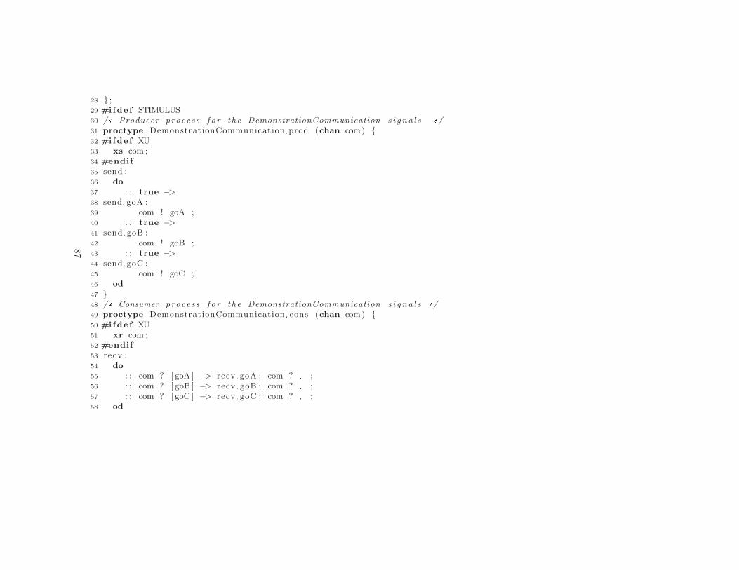
28 } ;29 #ifde f STIMULUS30 /* Producer process f o r the DemonstrationCommunication s i g na l s */31 proctype DemonstrationCommunication prod (chan com) {32 #ifde f XU33 xs com ;34 #endif
35 send :36 do
37 : : true −>
38 send goA :39 com ! goA ;40 : : true −>
41 send goB :42 com ! goB ;43 : : true −>
44 send goC :45 com ! goC ;46 od
47 }48 /* Consumer process f o r the DemonstrationCommunication s i g na l s */49 proctype DemonstrationCommunication cons (chan com) {50 #ifde f XU51 xr com ;52 #endif
53 recv :54 do
55 : : com ? [ goA ] −> recv goA : com ? ;56 : : com ? [ goB ] −> recv goB : com ? ;57 : : com ? [ goC ] −> recv goC : com ? ;58 od
87

Appendix
A.
Promela
model
example
59 }60 #endif
61
62 /* Capsu les */63 proctype Demonstrat ionCapsule (64 chan demoCom65 ) {66 #ifde f XU67 xr demoCom ;68 #endif
69 /* Incoming message v a r i a b l e s */70 DemonstrationCommunication demoCom msg ;71 /* Inter−connect ing channel s f o r contained cap su l e s */72 /* Local por t s */73 /* I n i t i a l i z a t i o n o f a l l contained cap su l e s . */74 atomic {75 skip
76 } ;77
78 Proper t i e sDemonst rat i on Demonst rat ionCapsu le S tat e Mach ine Reg ion1 in i t i a l :79 atomic {80 #ifde f VERBOSE81 printf ( ”MSC: i n i t i a l \n” ) ;82 #endif
83 i f
84 /* Take t r an s i t i o n I n i t i a l ( shor t name) */85 : : true −>
86 /* Trans i t i on code f o r t r a n s i t i o n I n i t i a l */87 /* Entry code f o r s t a t e StateA ( shor t name) */88 #ifde f VERBOSE89 printf ( ”MSC: StateA \n” ) ;
88

90 #endif
91 /* Jump to next s t a t e StateA ( shor t name) */92 goto Propert iesDemonstrat ion Demonstrat ionCapsu le State Machine Region1 StateA93
94 /* Dummy guard f o r s t a t e s w i thou t ou tgo ing t r a n s i t i o n s */95 : : fa l se
96 f i
97 }98
99 Propert iesDemonstrat ion Demonstrat ionCapsu le State Machine Region1 StateA :100 atomic {101 i f
102 /* Acquire message on por t demoCom */103 : : demoCom?demoCom msg −>
104 i f
105 /* Take t r an s i t i o n goToA ( shor t name) */106 : : demoCom msg . i d == goA −>
107 /* Exi t code f o r s t a t e StateA ( shor t name) */108 /* Trans i t i on code f o r t r a n s i t i o n goToA */109 /* Entry code f o r s t a t e StateA ( shor t name) */110 #ifde f VERBOSE111 printf ( ”MSC: StateA \n” ) ;112 #endif
113 /* Jump to next s t a t e StateA ( shor t name) */114 goto Propert iesDemonst rat ion Demonstrat ionCapsu le State Machine Region1 StateA115
116 /* Take t r an s i t i o n goToB ( shor t name) */117 : : demoCom msg . i d == goB −>
118 /* Exi t code f o r s t a t e StateA ( shor t name) */119 /* Trans i t i on code f o r t r a n s i t i o n goToB */120 /* Entry code f o r s t a t e StateB ( shor t name) */
89

Appendix
A.
Promela
model
example
121 #ifde f VERBOSE122 printf ( ”MSC: StateB \n” ) ;123 #endif
124 /* Jump to next s t a t e StateB ( shor t name) */125 goto Propert iesDemonst rat ion Demonstrat ionCapsu le State Machine Region1 StateB126
127 /* Take t r an s i t i o n goToC ( shor t name) */128 : : demoCom msg . i d == goC −>
129 /* Exi t code f o r s t a t e StateA ( shor t name) */130 /* Trans i t i on code f o r t r a n s i t i o n goToC */131 /* Entry code f o r s t a t e StateC ( shor t name) */132 #ifde f VERBOSE133 printf ( ”MSC: StateC \n” ) ;134 #endif
135 /* Jump to next s t a t e StateC ( shor t name) */136 goto Propert iesDemonstrat ion Demonstrat ionCapsu le State Machine Region1 StateC137
138 : : else −>
139 #ifde f VERBOSE140 printf ( ”MSC: Unhandled s i g n a l %e in StateA \n” , demoCom msg . i d ) ;141 #endif
142 assert ( fa l se ) ;143 /* Run the pan v e r i f i e r wi th ’−A’ to suppress a s s e r t i on v i o l a t i o n s */144 goto Propert iesDemonstrat ion Demonstrat ionCapsu le State Machine Region1 StateA145 f i
146
147 /* Trans i t i ons below l a c k t r i g g e r and are t h e r e f o r e d i s a b l e d by d e f a u l t */148 /* Dummy guard f o r s t a t e s w i thou t ou tgo ing t r a n s i t i o n s */149 : : fa l se
150 f i
151 }
90

152
153 Propert iesDemonstrat ion Demonstrat ionCapsu le State Machine Region1 StateC :154 atomic {155 i f
156 /* Acquire message on por t demoCom */157 : : demoCom?demoCom msg −>
158 i f
159 /* Take t r an s i t i o n goToC ( shor t name) */160 : : demoCom msg . i d == goC −>
161 /* Exi t code f o r s t a t e StateC ( shor t name) */162 /* Trans i t i on code f o r t r a n s i t i o n goToC */163 /* Entry code f o r s t a t e StateC ( shor t name) */164 #ifde f VERBOSE165 printf ( ”MSC: StateC \n” ) ;166 #endif
167 /* Jump to next s t a t e StateC ( shor t name) */168 goto Propert iesDemonstrat ion Demonstrat ionCapsu le State Machine Region1 StateC169
170 /* Take t r an s i t i o n goToA ( shor t name) */171 : : demoCom msg . i d == goA −>
172 /* Exi t code f o r s t a t e StateC ( shor t name) */173 /* Trans i t i on code f o r t r a n s i t i o n goToA */174 /* Entry code f o r s t a t e StateA ( shor t name) */175 #ifde f VERBOSE176 printf ( ”MSC: StateA \n” ) ;177 #endif
178 /* Jump to next s t a t e StateA ( shor t name) */179 goto Propert iesDemonst rat ion Demonstrat ionCapsu le State Machine Region1 StateA180
181 /* Take t r an s i t i o n goToB ( shor t name) */182 : : demoCom msg . i d == goB −>
91

Appendix
A.
Promela
model
example
183 /* Exi t code f o r s t a t e StateC ( shor t name) */184 /* Trans i t i on code f o r t r a n s i t i o n goToB */185 /* Entry code f o r s t a t e StateB ( shor t name) */186 #ifde f VERBOSE187 printf ( ”MSC: StateB \n” ) ;188 #endif
189 /* Jump to next s t a t e StateB ( shor t name) */190 goto Propert iesDemonst rat ion Demonstrat ionCapsu le State Machine Region1 StateB191
192 : : else −>
193 #ifde f VERBOSE194 printf ( ”MSC: Unhandled s i g n a l %e in StateC\n” , demoCom msg . i d ) ;195 #endif
196 assert ( fa l se ) ;197 /* Run the pan v e r i f i e r wi th ’−A’ to suppress a s s e r t i on v i o l a t i o n s */198 goto Propert iesDemonstrat ion Demonstrat ionCapsu le State Machine Region1 StateC199 f i
200
201 /* Trans i t i ons below l a c k t r i g g e r and are t h e r e f o r e d i s a b l e d by d e f a u l t */202 /* Dummy guard f o r s t a t e s w i thou t ou tgo ing t r a n s i t i o n s */203 : : fa l se
204 f i
205 }206
207 Propert iesDemonstrat ion Demonstrat ionCapsu le State Machine Region1 StateB :208 atomic {209 i f
210 /* Acquire message on por t demoCom */211 : : demoCom?demoCom msg −>
212 i f
213 /* Take t r an s i t i o n goToB ( shor t name) */
92

214 : : demoCom msg . i d == goB −>
215 /* Exi t code f o r s t a t e StateB ( shor t name) */216 /* Trans i t i on code f o r t r a n s i t i o n goToB */217 /* Entry code f o r s t a t e StateB ( shor t name) */218 #ifde f VERBOSE219 printf ( ”MSC: StateB \n” ) ;220 #endif
221 /* Jump to next s t a t e StateB ( shor t name) */222 goto Propert iesDemonstrat ion Demonstrat ionCapsu le State Machine Region1 StateB223
224 /* Take t r an s i t i o n goToA ( shor t name) */225 : : demoCom msg . i d == goA −>
226 /* Exi t code f o r s t a t e StateB ( shor t name) */227 /* Trans i t i on code f o r t r a n s i t i o n goToA */228 /* Entry code f o r s t a t e StateB ( shor t name) */229 #ifde f VERBOSE230 printf ( ”MSC: StateB \n” ) ;231 #endif
232 /* Jump to next s t a t e StateB ( shor t name) */233 goto Propert iesDemonstrat ion Demonstrat ionCapsu le State Machine Region1 StateB234
235 : : else −>
236 #ifde f VERBOSE237 printf ( ”MSC: Unhandled s i g n a l %e in StateB\n” , demoCom msg . i d ) ;238 #endif
239 assert ( fa l se ) ;240 /* Run the pan v e r i f i e r wi th ’−A’ to suppress a s s e r t i on v i o l a t i o n s */241 goto Propert iesDemonstrat ion Demonstrat ionCapsu le State Machine Region1 StateB242 f i
243
244 /* Trans i t i ons below l a c k t r i g g e r and are t h e r e f o r e d i s a b l e d by d e f a u l t */
93

Appendix
A.
Promela
model
example
245 /* Dummy guard f o r s t a t e s w i thou t ou tgo ing t r a n s i t i o n s */246 : : fa l se
247 f i
248 }249 }250
251 in i t {252 #ifde f STIMULUS253 chan DemonstrationCapsule demoCom = [CHANLEN] of { DemonstrationCommunication } ;254 /* Run top process and requ i red s t imu lus processes to c l o s e the model */255 atomic {256 run DemonstrationCommunication prod ( DemonstrationCapsule demoCom ) ;257 run Demonstrat ionCapsule ( DemonstrationCapsule demoCom )258 }259 #else
260 run Demonstrat ionCapsule ( )261 #endif
262 }
94

APPENDIX B
JET transformation templates
This appendix presents two of the templates that are part of the JET transfor-mation project. Listing B.1 contains the top-most template in the transforma-tion project and Listing B.2 contains the template that produces Promela codefor representing a state machine.
95

Appendix
B.
JET
transformatio
ntemplates
Listing B.1: Main template for model transformation.
1 <%−−2 Main template f o r model t ran s fo rmat ion .3 Inc ludes a l l templates nece s sary f o r generat ing a Promela model .4
5 Variab le dependenc ies : −6 −−%>
7
8 /* */9 /* This code was automat i ca l ly generated by the JET trans fo rmat ion */
10 /* emxtransform . pml . j e t */11 /* */12 /* Model name : <c : get s e l e c t =”/Model/@name” de f au l t=”unknown”/> */13 /* Package name : <c : get s e l e c t =”/Package/@name” de f au l t=”unknown”/> */14 /* */15
16 <%−− Generate d e f i n i t i o n s f o r Promela model . −−%>
17 <c : in c lude template=”templates / de f in i t i onTemp la t e s / genDe f i n i t i on s . pml . j e t ” />18
19 <%−− Generate ex t ra opt ion s f o r Promela model . −−%>
20 <c : in c lude template=”templates / optionTemplates /genOptions . pml . j e t ” />21
22 <%−− Generate communication p ro t o co l s f o r Promela model . −−%>
23 <c : in c lude template=”templates / protocolTemplates / genProtoco l s . pml . j e t ” />24
25 <%−− Generate a l l cap su l e p r o c e s s e s f o r Promela model . −−%>
26 <c : in c lude template=”templates / capsuleTemplates / genCapsules . pml . j e t ” />27
28 <%−− Generate i n i t i a l p roce s s f o r Promela model . −−%>
29 <c : in c lude template=”templates / in i tTemp lat e s/ gen In i t . pml . j e t ” />
96

Listing B.2: Template for state machine generation.
1 <%−−2 Template f o r generat ion o f a capsu le ’ s s t a t e machine .3 Separates the generat ion o f the s t a t e machine ’ s p seudos tat e s4 and ord inary s t a t e s .5
6 Variab le dependenc ies : cap su l e7 −−%>
8
9 <c : s e tVar i ab l e s e l e c t=”$capsu l e /StateMachine ” var=”statemach ine” />10
11 <%−− Pseudostates generat ion . −−%>
12 <c : i t e r a t e s e l e c t=”$statemach ine/ reg ion /Pseudostate [ @kind = ’ i n i t i a l ’ ] ” var=”pseudostate ”>13 <f : r ep l a c eA l l value =”[ˆ\\w]” replacement=” ” regex=”t rue”><c : get s e l e c t=”$pseudostate /owner/
@qualifiedName” /></ f : r ep laceA l l > i n i t i a l :14 atomic {15 #i f d e f VERBOSE16 p r i n t f (”MSC: i n i t i a l \n”) ;17 #end i f18 i f19 /* Take t r an s i t i o n <c : get s e l e c t=”$pseudostate / outgoing /@name” /> ( shor t name) */20 : : t rue −>
21 /* Trans i t i on code f o r t r a n s i t i o n <c : get s e l e c t=”$pseudostate / outgoing /@name” /> */22 <c : get s e l e c t=”$pseudostate / outgoing/ e f f e c t /@body” d e f au l t =””/>23
24 /* Entry code f o r s t a t e <c : get s e l e c t=”$pseudostate / outgoing / t a r g e t /@name” /> ( shor t name) */25 #i f d e f VERBOSE26 p r i n t f (”MSC: <c : get s e l e c t=”$pseudostate / outgoing/ t a r g e t /@name” /> \n”) ;27 #end i f28 <c : get s e l e c t=”$pseudostate / outgoing/ t a r g e t / entry /@body” d e f au l t =””/>29
97

Appendix
B.
JET
transformatio
ntemplates
30 /* Jump to next s t a t e <c : get s e l e c t=”$pseudostate / outgoing/ t a r g e t /@name” /> ( shor t name) */31 goto < f : r ep l a c eA l l value =”[ˆ\\w]” replacement=” ” regex=”t rue”><c : get s e l e c t=”$pseudostate /
outgoing / t a r g e t /@qualifiedName” /></f : r ep laceA l l >
32 /* Dummy guard f o r s t a t e s without outgoing t r a n s i t i o n s */33 : : f a l s e34 f i35 }36 </c : i t e r a t e >
37
38 <%−− Ordinary s t a t e s generat ion . −−%>
39 <c : i t e r a t e s e l e c t=”$statemach ine/ reg ion / State ” var=”s t a t e ”>40 < f : r ep l a c eA l l value =”[ˆ\\w]” replacement=” ” regex=”t rue”><c : get s e l e c t=”$ s t a t e /@qualifiedName” /></f :
r ep laceA l l >:41 atomic {42 i f43 <c : i t e r a t e s e l e c t=”$capsu l e /ownedPort [44 ( s t e r e o t yp e ( . , ’UMLRealTime : : RTPort ’ ) /@isConjugate = ’ f a l s e ’45 and count ( . / type /owner/CallEvent [ s t e r e o t yp e ( . , ’UMLRealTime : : InEvent ’ ) ] ) \> 046 )47 or48 ( s t e r e o t yp e ( . , ’UMLRealTime : : RTPort ’ ) /@isConjugate = ’ true ’49 and count ( . / type /owner/CallEvent [ s t e r e o t yp e ( . , ’UMLRealTime : : OutEvent ’ ) ] ) \> 050 )51 ] ” var=”port”>52 /* Acquire message on port <c : get s e l e c t=”$port /@name” /> */53 : : <c : get s e l e c t=”$port /@name” />?<c : get s e l e c t=”$port /@name” /> msg −>
54 i f55 <c : i t e r a t e s e l e c t=”$ s t a t e / connect ionPoint [ . / outgoing / t r i g g e r / port /@name = $port /@name] ” var=”cp”>56 /* Take t r an s i t i o n <c : get s e l e c t=”$cp/ outgoing/@name” /> ( shor t name) */57 : : <c : get s e l e c t=”$port /@name” /> msg . i d == <c : get s e l e c t=”$cp/ outgoing/ t r i g g e r / event /
operat ion /@name” /> −>
98
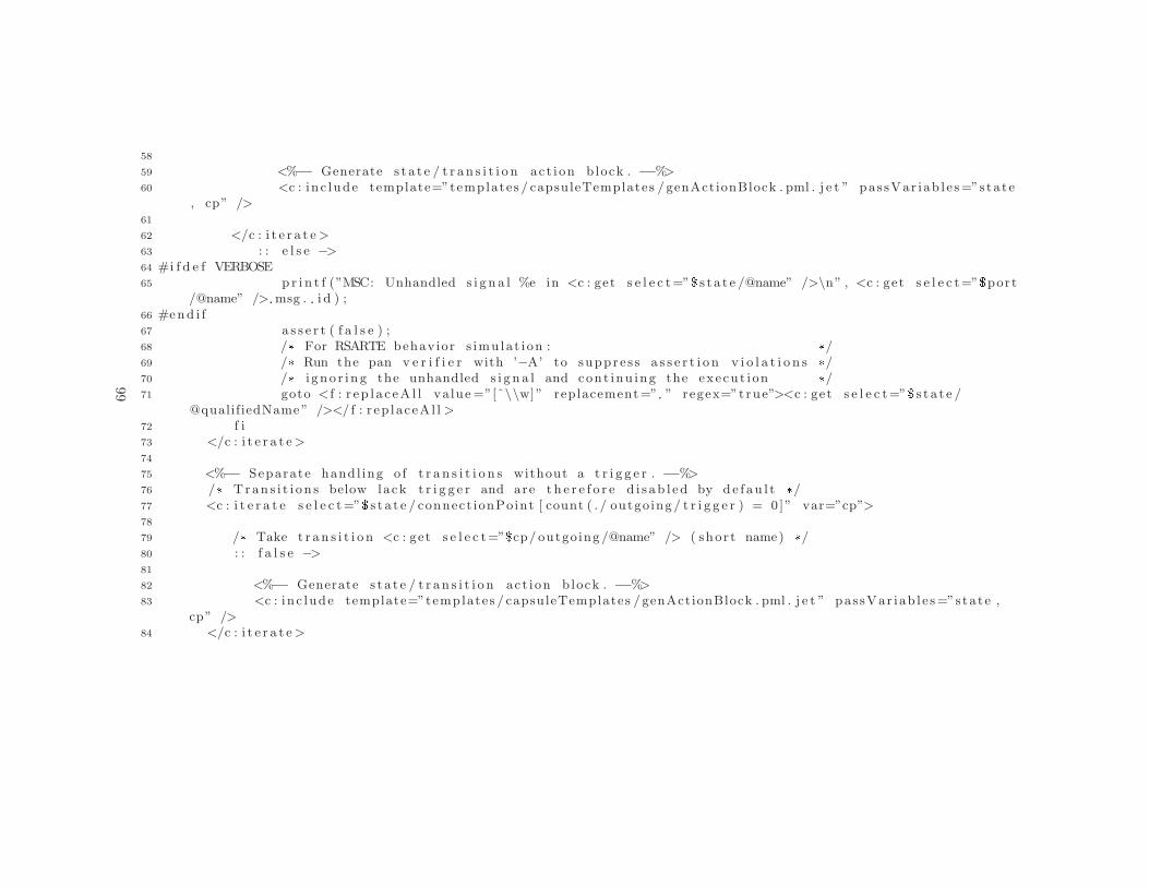
58
59 <%−− Generate s t a t e / t r an s i t i o n act ion b lock . −−%>
60 <c : in c lude template=”templates / capsuleTemplates / genActionBlock . pml . j e t ” pas sVar iab l e s=”stat e, cp” />
61
62 </c : i t e r a t e >
63 : : e l s e −>
64 #i f d e f VERBOSE65 p r i n t f (”MSC: Unhandled s i g n a l %e in <c : get s e l e c t=”$ s t a t e /@name” />\n” , <c : get s e l e c t=”$port
/@name” /> msg . i d ) ;66 #end i f67 a s s e r t ( f a l s e ) ;68 /* For RSARTE behav ior s imu lat ion : */69 /* Run the pan v e r i f i e r with ’−A’ to suppre s s a s s e r t i o n v i o l a t i o n s */70 /* i gn o r i n g the unhandled s i g n a l and cont inu ing the execu t ion */71 goto < f : r ep l a c eA l l value =”[ˆ\\w]” replacement=” ” regex=”t rue”><c : get s e l e c t=”$ s t a t e /
@qualifiedName” /></ f : r ep laceA l l >
72 f i73 </c : i t e r a t e >
74
75 <%−− Separate handl ing o f t r a n s i t i o n s without a t r i g g e r . −−%>
76 /* Tran s i t i on s below lack t r i g g e r and are t h e r e f o r e d i s ab l ed by de f au l t */77 <c : i t e r a t e s e l e c t=”$ s t a t e / connect ionPoint [ count ( . / outgoing / t r i g g e r ) = 0 ]” var=”cp”>78
79 /* Take t r an s i t i o n <c : get s e l e c t=”$cp/ outgoing /@name” /> ( shor t name) */80 : : f a l s e −>
81
82 <%−− Generate s t a t e / t r an s i t i o n act ion b lock . −−%>
83 <c : in c lude template=”templates / capsuleTemplates / genActionBlock . pml . j e t ” pas sVar iab l e s=”stat e ,cp” />
84 </c : i t e r a t e >
99

Appendix
B.
JET
transformatio
ntemplates
85
86 /* Dummy guard f o r s t a t e s without outgoing t r a n s i t i o n s */87 : : f a l s e88
89 f i90 }91 </c : i t e r a t e >
92
100