Formal Verificaction of the ADSP-2100 Processor...
28
1 Formal Verificaction of the ADSP-2100 Processor Using the HOL Theorem Prover Ali Habibi 1 , Sofiène Tahar 1 and Adel Ghazel 2 1 Electrical & Computer Engineering Department, Concordia University Montreal, Quebec, H3G 1M8 Canada {habibi, tahar}@ece.concordia.ca 2 École Superieure Des Communications de Tunis 2083 Ariana, Tunisia. [email protected] Technical Report March 2002 Abstract. In this technical report, we present the application of formal verification to digi- tal signal processors of the family ADSP-2100 using the HOL (Higher Order Logic) theo- rem prover. To solve the problem of complexity related to the big number of parameters of the processor, we used a structured method based on our knowledge about this processors family. In this method, we worked on the units of the processor as separate sub-systems in order to simplify their specifications by omitting the internal signals. We showdetails of the specification and verification strategies used and displayexperimental results as well the lessons learned. 1. Introduction Hardware and software systems are growing everyday in scale and functionality. This increase in complexity increases the number of subtle errors. Moreover, some of these errors may cause catastrophic loss of money, time, or even in many cases human life. A major goal of software engineering or system design is to enable developers to construct systems that operate reliably despite this complexity. One way of achieving this goal is by using formal methods, which are mathematically-based languages, techniques, and tools for specifying and verifying such systems [9]. Even formal methods do not a priori guar- antee correctness, they can greatly increase our understanding of a system by revealing inconsistencies, ambiguities, and incompleteness that might otherwise go undetected. In the past, the use of formal methods in practice seemed hopeless. The notations were too obscure, the techniques did not scale, and the tool support was inadequate or too hard to use. There were only a few non-trivial case studies and together they still were not con- vincing enough to the practicing software or hardware engineer. Few people had the train- ing to use them effectively on the job [6]. Only recently have we begun to see a more promising picture for the future of formal methods. For software specification, industry is open to trying out notations like Z to doc-
Transcript of Formal Verificaction of the ADSP-2100 Processor...

1
Formal Verificaction of the ADSP-2100 ProcessorUsing the HOL Theorem Prover
Ali Habibi1, Sofiène Tahar1 and Adel Ghazel2
1 Electrical & Computer Engineering Department, Concordia UniversityMontreal, Quebec, H3G 1M8 Canada
{habibi, tahar}@ece.concordia.ca2 École Superieure Des Communications de Tunis
2083 Ariana, [email protected]
Technical Report
March 2002
Abstract.In this technical report, we present the application of formal verification to digi-tal signal processors of the family ADSP-2100 using the HOL (Higher Order Logic) theo-rem prover. To solve the problem of complexity related to the big number of parameters ofthe processor, we used a structured method based on our knowledge about this processorsfamily. In this method, we worked on the units of the processor as separate sub-systems inorder to simplify their specifications by omitting the internal signals. We showdetails ofthe specification and verification strategies used and displayexperimental results as wellthe lessons learned.
1. IntroductionHardware and software systems are growing everyday in scale and functionality. Thisincrease in complexity increases the number of subtle errors. Moreover, some of theseerrors may cause catastrophic loss of money, time, or even in many cases human life. Amajor goal of software engineering or system design is to enable developers to constructsystems that operate reliably despite this complexity. One way of achieving this goal is byusing formal methods, which are mathematically-based languages, techniques, and toolsfor specifying and verifying such systems [9]. Even formal methods do not a priori guar-antee correctness, they can greatly increase our understanding of a system by revealinginconsistencies, ambiguities, and incompleteness that might otherwise go undetected.In the past, the use of formal methods in practice seemed hopeless. The notations were tooobscure, the techniques did not scale, and the tool support was inadequate or too hard touse. There were only a few non-trivial case studies and together they still were not con-vincing enough to the practicing software or hardware engineer. Few people had the train-ing to use them effectively on the job [6].Only recently have we begun to see a more promising picture for the future of formalmethods. For software specification, industry is open to trying out notations like Z to doc-

2
ument a system's properties more rigorously. For hardware verification, industry is adopt-ing techniques like model checking and theorem proving to complement the moretraditional one of simulation. In both areas, researchers and practitioners are performingmore and more industrial-sized case studies, and thereby gaining the benefits of using for-mal methods. Actually there are many tools performing hardware verification. Principallythe two approaches model checking and theorem proving are getting more interest.Notable examples about using theorem proving are describered in the literature [12]. Themost related to our study is the Motorola CAP [6]. During 1992-1996 Brock of Computa-tional Logic, Inc., working in collaboration with Motorola designers, developed an ACL2specification of the entire Motorola Complex Arithmetic Processor (CAP), a microproces-sor for digital signal processing (DSP). The CAP is the most complicated microprocessoryet formalized, with a three stage pipeline, six independent memories, four multiplier-accumulators, over 250 programmer-visible registers, and an instruction set allowing thesimultaneous modification of well over 100 registers in a single instruction. The formalspecification tracked the evolving design and included a simpler non-pipelined view thatwas proved equivalent on a certain class of programs. Finally, Brock used ACL2 to verifythe binary microcode for several DSP algorithms [5].The verification of the processor ADSP-2100 is very similar in complexity to the MotorolaCAP. However, we use the HOL theorem prover [7] and our object is to verify all theinstruction set of the processor. The ADSP-2100 family is a collection of programmablesingle-chip microprocessors that share a common base architecture optimized for digitalsignal processing (DSP) and other high-speed numeric processing applications. The vari-ous family processors differ principally in the type of on-chip peripherals they add to thebase architecture. On-chip memory, a timer, serial port(s), and parallel ports are availablein different members of the family.The HOL system is an interactive environment for machine-assisted theorem-proving inhigher-order logic [10]. The HOL logic is simple but expressive, incorporating higher-order functions and Milner-style polymorphism [4,7]. HOL uses the programming lan-guage ML to program proof strategies [11]. Theorems are encoded via an abstract typewhose only constructors are the primitive inference rules of the logic. Other proof strate-gies ultimately resolve into these steps. This combines a high degree of security with greatflexibility: the user can safely extend the inference system without being a logician. Alarge number of derived rules have been programmed for, e.g., proving facts in lineararithmetic, defining recursive datatypes or handling inductive definitions. The strength ofHOL comes from two principles proprieties. First backward (goal-directed) proof is sup-ported, and may be freely mixed with forward proof. Second, adherence to definitionalextension guarantees that the consistency of the logic is not compromised [1].The first part of this report presents the specification of the ADSP-2100 signal processor.In the verification section, we highlight the approach we used to deal with the complexityof this digital signal processor. The third and final part of this report outlines the generalremarks coming out from this study and the future directions of the formal verification.
2. The ADSP-2100 Family
2.1. Basic UnitsThe processors of the ADSP-2100 family have the same internal architecture described inFigure 1. This architecture has three separated computational units: Arithmetic and LogicUnit (ALU), Multiplier/Accumulator (MAC) and the Barrel Shifter. These units treat 16bits fixed point data [3].

3
Figure 1. ADSP 2100 Processor Architecture [2]
The two Address Generators and the Program Sequencer are responsible of the addressingmanagement. The use of two address generators allow the execution of two data reading(fetch) from the external memory. In the program sequencer has some embedded unitsallowing the execution of internal loops which increases the efficiency of the processor[14].
The principal characteristic of this family of processors is that it is based on a modifiedHarvard architecture [8]. In fact, data is stored in both the data and the program memories.This is very important because it allows the execution of two instructions in the sameclock cycle.
2.2. Buses
The processor ADSP-2100 has five internal buses. These interconnect the internal unitstogether and allow them to read (store) data from (to) the external memories.
2.2.1. PMA Bus (Program Memory Address)According to the actual instruction, the program sequencer generates the new address.This later is written in the PMA bus, 14-bit bus, which enables addressing up to 14KB ofexternal program memory and 14KB of external data memory. The distinction betweenthe two memories is defined according to the pin PMDA.
2.2.2. PMD Bus (Program Memory Data)This bus serves to load instructions from the external memory to the internal instructions’register. Instructions are loaded during one clock cycle and are executed in the next cyclesimultaneously with loading the next instruction. All loaded instructions are also writtenin the cache memory.
2.2.3. DMA Bus (Data Memory Address)This is a 14 bit bus allowing the direct access to a 16KB external data memory. The dataaddresses can be provided by two different sources: an absolute value defined by theinstruction (direct addressing) or the output of one of the two address generators (indirectaddressing).
CLKIN
Program Memory Address
Program Memory Data
TRAP
PROGRAMMEMORY 24
14
RESET HALT
ClockData AddressGenrator #1
Data AddressGenrator #1
ProgramSequencer
ALU
Input Regs
Output Regs
MAC
Input Regs
Output Regs
Shifter
Input Regs
Output Regs
PMA BUS
DMA BUS
PMD BUS
DMD BUS
R BUS16
16
14
24
14CLKOUT
Data Memory Address
Data Memory Data
IRQ BR BG
14
16
DATAMEMORYData
ADDR
PERIPHERALS
Data
ADDR

4
2.2.4. DMD BusThis is a 16 bit bus that allows the access the content of any register and to transfer thiscontent to any other register or any external memory. This transfer take one clock cycle.
2.2.5. R BusThe units of the processor are organized to work in parallel. To eliminate any possibledelay, the internal bus R is used to transfer data between the registers of the three compu-tational units of the processor (ALU, MAC, SHIFTER). This a direct transfer which takesa unique clock cycle.
2.2.6. MemoryThe architecture of the family of processors ADSP-2100 allows the storage of data in thedata memory and data mixed with instructions in the program memory. Every processorcontains one RAM and/or one ROM.
2.3. Instruction Set of the ADSP-2100 Family
The instruction set of the ADSP-2100 family has two principle proprieties: the classifica-tion of the instructions and the multiplicity of instructions per command [2]. The instruc-tions are classified by the concerned unit. In other terms, the instructions of the ALU havethe same format that is different form that of the program sequencer for example. On theother hand, the majority of the instructions are composed in two parts: the first is a mem-ory access (for reading or writing) and the second is an operand execution (ADD operandfor example).The general format of the instructions is described in Figure 2. It is composed from twoprincipal parts: the identifier of the instruction and the parameters of the instructions. Inthe Figure 4.3, the example of the general instruction executing of an operation related tothe ALU with two data reading operations the first from the program memory and the sec-ond from the data memory.
Example: Opcode type 1
Figure 2. General Format of the Instructions of the ADSP-2100 Family [2]
The instructions of the ADSP-2100 family can be classified into the following classes :
1. MAC/ALU instructions with memory access: they concern the operations done by theALU and MAC units with memory access for reading.
2. Memory access instructions: they allow the allow the access to the data and programmemories in read/write modes.
General Format:
Opcode Identifier Opcode Parameters

5
3. MAC/ALU instructions with inter-registers data transfer: they allow the execution ofALU/MAC operations with an inter-register data transfer.
4. Registers direct access instructions: they allow reading the content of one of the regis-ters of the three computational units (ALU, MAC and Shifter).
5. Conditional MAC/ALU instructions: they allow the execution of one ALU/MACinstruction when a condition, based on one of the output signals of one of the computa-tional units, is satisfied.
6. Shift instructions: they concern the operations relative to the Shifter unit.
7. Mode control instructions: they allow the change of the processor working modes. Thisis the case for example if we want to change the active set of registers.
8. Program sequence instructions: these are the JUMP, the conditional JUMP and the DOUNTIL loop instructions.
9. Division instructions: they concern the operations of division done by the two sub-unitsDIVS and DIVQ.
10.Control instructions: these are the NOP (No Operation) and Idle operations.
3. Formal Verification with Theorem Proving
3.1. HOL LogicThe HOL language is a variant of Church's simple theory of types. The syntax and seman-tics of the particular logical system supported by HOL [1] is described in detail in theTable 1. The meta-language for this description will be English, enhanced with variousmathematical notations and conventions. The object language of this description is theHOL logic.
3.2. HOL SystemThe HOL system [4] is a powerful and widely used computer program for constructingformal specifications and proofs in higher order logic. The system is used in both industryand academia to support formal reasoning in many different areas, including hardwaredesign and verification, reasoning about security, proofs about real-time systems, seman-tics of hardware description languages, compiler verification, program correctness, model-ing concurrency, and program refinement. HOL is also used as an open platform forgeneral theorem-proving research.HOL uses the programming language ML [10] to program proof strategies. Theorems areencoded via an abstract type whose only constructors are the primitive inference rules ofthe logic. Other proof strategies ultimately resolve into these steps. This combines a highdegree of security with great flexibility: the user can safely extend the inference systemwithout being a logician. A large number of derived rules have been programmed for, e.g.,proving facts in linear arithmetic, defining recursive datatypes or handling inductive defi-nitions. (The large user base contributes to the stock of derived rules.) Backward (goal-directed) proof is supported, and may be freely mixed with forward proof.HOL as a theorem prover can deal directly with infinite state spaces [14]. It relies on tech-niques like structural induction to prove over infinite domains. Interactive theorem prov-ers, by definition, require interaction with a human, so the theorem proving process is slow

6
and often error-prone. In the process of finding the proof, however, the human user oftengains invaluable insight into the system or the property being proved.
3.3. ML Language
ML is a general purpose functional language [11] which has been used extensively atCambridge University, Edinburgh University, INRIA and elsewhere for implementing the-orem provers. The HOL system is written and embedded in ML. HOL proofs are ML pro-grams and so must conform to the syntax and semantics of ML.
There are several reasons why ML is a suitable language in which to write theorem prov-ers. First it has a strong yet flexible type system. Typing is used at compile time to checkthat things are used in a manner consistent with their definition. For example, in the imple-mentation of HOL we define a typethm (theorem) and the ML compiler uses its strongtyping to ensure that if either an argument to a function or the result returned by a functionis supposed to be of typethm , then it is.
Second, ML has abstract datatypes which are used to group together a datatype and opera-tions over it. Abstract datatypes are written in such a way that direct access to the datatypeconstructors is not possible. Instances of the data type can be created and accessed onlythrough specially tailored functions defined within the abstract definition. HOL imple-ments theorems as an abstract datatype and supplies only one mechanism for generatingnew theorems, namely the inference rule.
Finally, ML supports and encourages the use of functions as first-class values. Patterns ofML commands in HOL proofs can be readily combined into more powerful commands.Common higher-level commands may be named and saved for later use, thus raising thelevel of abstraction and understanding.
Table 1. Terms of the HOL Logic [7]
Kind of term HOL notation Standard notation Description
Truth T T true
Falsity F ^ false
Negation ~t ¬ t not t
Disjunction t1\/ t2 t1∨ t2 t1 or t2
Conjunction t1/\ t2 t1∧ t2 t1 and t2
Implication t1==>t2 t1 ⇒ t2 t1 implies t2
Equality t1=t2 t1 = t2 t1 equals t2
∀-quantification ! x. t ∀ x. t for all x: t
∃-quantification ?x. t ∃ x. t for some x: t
ε-term @x. t ε x. t an x such that: t
Conditional if t then t1 else t2 (t→ t1, t2) if t then t1 else t2
7
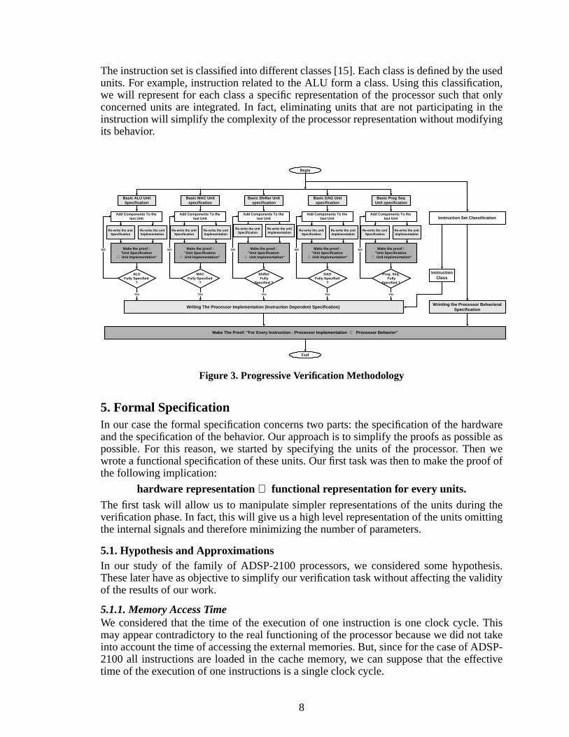
4. Specification and Verification Methodology
4.1. Problem Description and Proposed SolutionThe classical way of using HOL in the verification of a processor is to perform the follow-ing steps [10]:
1. Write the specification of the behavior of the processor (according to the HOL syntax).
2. Write the specification of the implementation of the processor (according to the HOLsyntax).
3. Make the proof (using HOL) of the implication: “Processor Implementation⇒ Proces-sor Specification”.
This classical way of verifying processors cannot be used to verify a DSP processor. Infact, the complexity of a DSP processor in terms of number of variables, variable typesand the variety of instructions makes it impossible the use of this direct way [6].We propose to define a methodology for the verification of the DSP processor. This meth-odology will satisfy certain characteristics to guarantee its capability to deal with the pro-cessor features, to take advantage from the processor architecture and to prepare the proofgoal in the simplest way to the HOL system.The methodology that we defined is described in Figure 3 including four principle steps.First, we simplify the processor units’ specifications. Next, we construct the specificationof the implementation of the processor. Then, we write the specification of the behavior ofthe processor. Finally, we make the proof of the goal “Processor Implementation⇒ Pro-cessor Specification” for every instruction.The unit simplification task is an obligatory task if we want to succeed in the verificationof the processor. In fact, to our best knowldge there is no work that did the verification ofthe instruction set of a DSP commercial processor. Even [6] has just made the specifica-tion of the processor. The cause of the difficulty of that task comes from the size of thespecifications. In fact, the specification of the implementation of any commercial DSPprocessor (in ML for our case for example) takes more than thousand pages. So, just writ-ing it will be very complex. Then what about manipulating such a long specification usinga theorem prover while constructing complex proofs! The more reductions we are able toperform, the more the chances to achieve our verification goal of the full instruction set ofthe processor are higher.
4.2. Simplification of the Processor UnitsBefore writing the full specification of the implementation of the processor, we have tosimplify the units implementations. This step allows the minimization of the number ofvariables and parameters used in the specification of the processor. This is done by elimi-nating the internal signals in each unit.We use a progressive method in simplifying the units specifications. We start by the basiccomponent in the unit. Then we add the components of the unit one by one and simplifythe new representation by eliminating the new internal signals. This step is repeated untilthe full unit is constructed. This can be seen as the re-assembling of the unit from its com-ponents.
4.3. Constructing the Specification of the Processor ArchitectureTo construct the instruction dependent specification of the implementation of the proces-sor, we use both the specification of the processor units, defined in the previous step, and aclassification of the instruction set.
8
The instruction set is classified into different classes [15]. Each class is defined by the usedunits. For example, instruction related to the ALU form a class. Using this classification,we will represent for each class a specific representation of the processor such that onlyconcerned units are integrated. In fact, eliminating units that are not participating in theinstruction will simplify the complexity of the processor representation without modifyingits behavior.
Figure 3. Progressive Verification Methodology
5. Formal SpecificationIn our case the formal specification concerns two parts: the specification of the hardwareand the specification of the behavior. Our approach is to simplify the proofs as possible aspossible. For this reason, we started by specifying the units of the processor. Then wewrote a functional specification of these units. Our first task was then to make the proof ofthe following implication:
hardware representation⇒ functional representation for every units.The first task will allow us to manipulate simpler representations of the units during theverification phase. In fact, this will give us a high level representation of the units omittingthe internal signals and therefore minimizing the number of parameters.
5.1. Hypothesis and ApproximationsIn our study of the family of ADSP-2100 processors, we considered some hypothesis.These later have as objective to simplify our verification task without affecting the validityof the results of our work.
5.1.1. Memory Access TimeWe considered that the time of the execution of one instruction is one clock cycle. Thismay appear contradictory to the real functioning of the processor because we did not takeinto account the time of accessing the external memories. But, since for the case of ADSP-2100 all instructions are loaded in the cache memory, we can suppose that the effectivetime of the execution of one instructions is a single clock cycle.
Begin
Writing The Processor Implementation (Instruction Dependent Specification)
InstructionClass
End
Basic ALU UnitSpecification
NO
ALUFully Specified
?
Yes
Instruction Set Classification
Wrinting the Processor BehavioralSpecification
Make The Proof: "For Every Instruction : Processor Implementation ⇒ Processor Behavior"
Make the proof :"Unit Specification
⇒ Unit Implementation"
Basic MAC Unitspecification
NO
MACFully Specified
?
Yes
Make the proof :"Unit Specification
⇒ Unit Implementation"
Basic Shifter Unitspecification
NO
Shifter Fully
Specified ?
Yes
Make the proof :"Unit Specification
⇒ Unit Implementation"
Basic DAG Unitspecification
NO
DAGFully Specified
?
Yes
Make the proof :"Unit Specification
⇒ Unit Implementation"
Basic Prog SeqUnit specification
NO
Prog. Seq. Fully
Specified ?
Yes
Make the proof :"Unit Specification
⇒ Unit Implementation"
Add Components To thelast Unit
Add Components To thelast Unit
Add Components To thelast Unit
Add Components To thelast Unit
Add Components To thelast Unit
Re-write the unitSpecification
Re-write the unitImplementation
Re-write the unitSpecification
Re-write the unitImplementation
Re-write the unitSpecification
Re-write the unitImplementation
Re-write the unitSpecification
Re-write the unitImplementation
Re-write the unitSpecification
Re-write the unitImplementation

9
5.1.2. Transfer of Data in the BusesWe considered that the data is transferred from/to buses is instantaneous. This is not con-tradictory with reality since this action is very short compared to the clock cycle duration.Therefore, the fact of setting its value to zero will not affect of the global behavior of thereal system.
5.1.3. Registers AccessRegisters are accessed at the begging of the clock cycle for writing and at the end of theclock cycle for reading. In our representation this will be seen as the value presented in theoutput of a register att is that was in its input att-1 (i.e. at the end of the last cycle). Thisrepresentation keep the content of the register correct at any timet and make it easy tomanipulate the registers while making the proofs.
5.2. Components SpecificationIn our manipulation of the ADSP-2100 processors family we manipulated many datatypes. These are summarized in Table 2.
5.2.1. MultiplexersIn each unit of the processors there are many multiplexers allowing the selection betweenthe possible inputs and their direction to the corresponding outputs. An enumeration of allthe multiplexers used in the ADSP-2100 family has given us seven classes that are used.For this reason, we wrote the specification of these classes only. We considered in ourspecification that the transfer of data between the input and output is instantaneous. This isnot contradictory with the reality because the transfer time is very short.Table 3 illustrates the classes of multiplexers used in the specification of the units of theprocessors ADSP-2100.The following specification, written in ML, presents the case of one multiplexer of theclass 4. In this case, the multiplexer has two inputs the first of type Word8 and the secondof type Word16, and one output of type Word8. The selection between the two inputs isdone according to the value of the boolean parameterinput_selectwhich, when set to true(T) gives the first input to the output and when set to false (F) gives the second input to theoutput:
MUX_8_16_8 = Define(`MUX_8_16_8
(FromWord16ToWord8 :word16 -> word8)(input1 :num -> word8, input2 :num -> word16, output :num -> word8, input_select :num -> bool)=( !t :num.
( ( input_select t = T ) /\ ( output t = input1 t ) )\/ ( ( input_select t = F ) /\ ( output t = ( FromWord16ToWord8 (input2 t) ) ))
)`);
This defines for every timet, the output of the multiplexeroutput is given by:1. The input oneinput1 if the selection parameterinput_select is at the valueT.2. The input twoinput2 if the selection parameterinput_select is at the valueF.The HOL system reply to the last specification by saying that the last definition is wellformed. It stores it then as theorem calledMUX_8_16_defwhich is of the reserved typeThm.thm.
10
Table 2. The Data Types used in the Specification of the Processor ADSP-2100
Type Meaning Comments
Bool Type Boolean : True or False. This type concerns the control bits and the output flagsof the computational units of the processor.
Word5 5 bits word. This type concerns the exponent parameter of the Shifterunit.
Word8 8 bits word This type concerns the shift parameter of the Shifter unitand the third register of the MAC unit.
Word14 14 bits word This is the type of the PMA and DMA buses.
Word16 16 bits word This type concerns the majority of the input/output reg-isters of the units of the processor. It concerns also thePMD and R buses.
Word24 24 bits word This type concerns the bus PMD which allows theaccess to the program memory.
Word32 32 bits word This type concerns the output of the bloc ShifterArray ofthe unit Shifter.
Word40 40 bits word This type concerns the first input of the bloc ADD/SUB-STRACT of the unit MAC.
Num A natural value. This type is used to represent the time (t).
OpCode Vector of 24 boolean The representation of the instructions codes.

11
5.2.2. Registers
The units of the processor contain a large number of registers that are distinguished bytheir sizes and by their structures. In fact, the sizes of the registers vary depending on thetask to which they are affected. On the other hand, many registers are grouped together toform the same entity. Another fact, is that all the registers are duplicated, so in an interrup-tion the processor uses the second bank of registers without affecting the contents of thefirst bank of registers.
Table 4 summarises the classes of the registers that we defined for the hardware specifica-tion of the units of the processor.
The following code illustrates the specification of the register AF of the ALU which is ageneric representation of the members of the registers of the class 1. We considered theinput of the registerAF_input, the output of the registerAF_outputand the parameterbanc_select. This last is a Boolean that controls the used banks of registers.
Table 3. The Classes of Multiplexers
Class Inputs Output
Number Type Type
1 2 (Word16,Word16) Word16
2 2 (Word16,Word8) Word16
3 2 (Word16,Word8) Word8
4 2 (Word8,Word16) Word8
5 2 (Word8,Word16) Word5
6 2 (Word14,Word16) Word14
7 3 (Word8,Word8,Word8) Word8
Table 4. The Classes of Registers
Class Number of registers Size(number of bits) Examples
1 1 16 Registers AF and AR in ALU.
2 2 2x16 The register AX which is composed of thetwo sub-registers AX0 and AX1.
3 1 8 Register MR2 of the unit MAC.
4 1 5 Register SB of the unit Shifter.
5 4 4x14 Register I of the address generator whichis composed of 4 sub-registers each ofthem is a 14 bits register.

12
ALU_AF_reg = (`ALU_AF_reg(AF_input, AF_output, bank_select) =
!t .
(? AF_output_bank0 AF_output_bank1 .
(
(bank_select t = T) => ( if (t = 0) then F else (AF_output_bank0 t = AF_input (t-1)) )\
| ( if (t = 0) then F else (AF_output_bank1 t = AF_input (t-1)) )
) /\ (
(bank_select t = T) => (AF_output t = AF_output_bank0 t)| (AF_output t = AF_output_bank1 t)
) )
`);
This defines for every timet, the output of the registerAF_outputcorresponds to its inputat the time (t-1). We used also the parameterbanc_selectto make the selection betweenthe two possible banks.
5.2.3. Data BusesIn our representation of data buses we considered that the output of the bus corresponds toits input at the same instant. This approximation did not alter the real functioning mode ofthe processor. In fact, the data is read at the beginning of the cycle and is written at its end.We wrote a simple representation of all the buses to have a clear and simple representationof the processor. The case of the specification of the bus PMA is illustrated in the follow-ing:
PMABusImp = (`PMABusImp(PMABusInput :num -> word14,PMABusOutput :num -> word14, t:num) =
(
(PMABusOutput t) = (PMABusInput t)
)
`);
5.2.4. Memory AccessThe family of processors ADSP-2100 contains three types of memory: BOOT memory,program memory and data memory. The program and data memories can be read and writ-ten. But the BOOT memory can be accessed only for reading. To represent the modes ofaccessing the memory, we considered 4 functions that, according to their input parameters,access one of three memories. Table 5 illustrates these four functions.The memory access functions take in their consideration the parametersRD_LOW(READ) andWR_LOW(WRITE) that controls reading and writing operations. This isillustrated in the specification of the operationstoredata:
!program_mem_data data_mem_data Index_register Modify_register PMS_low DMS_low RD_lowWR_low data_to_write t.store_data program_mem_data data_mem_data
(Index_register,Modify_register,PMS_low,DMS_low,RD_low,WR_low, data_to_write,t) =((RD_low t,WR_low t) = (T,F))
/\ (((PMS_low t,DMS_low t) = (F,T))\/ (data_to_write t = program_mem_data (Index_register (t - 1)) (Modify_register (t - 1)) (t - 1))/\ ((PMS_low t,DMS_low t) = (T,F)))

13
5.3. Units SpecificationFor every unit of the processor, we defined a behavioral specification and a hardware spec-ification of the unit. This is done to simplify the instruction verification task by manipulat-ing a simple representation of the processor.
5.3.1. Hardware Specification of the ALUThe ALU, see Figure 4, is the unit responsible for the arithmetic and logic operations. It iscomposed of a group of input registers, a group of output registers, many multiplexers andone base unit making the arithmetic and logic operations.To specify the ALU we considered the specifications of the registers and the multiplexerspreviously presented. The basic unit of the ALU is presented by many functions that get asinputs two parameters X and Y and give as output one result R plus the control flags. Theparameters of input/outputs that we used are defined in the Table 6.
Table 5. The Memory Access Functions
Function Parameters Access
fetch_data
(BMS_low, PMS_low, DMS_low) =(F,T,T)
Read data from the boot memory.
(BMS_low, PMS_low, DMS_low) =(T,F,T)
Read data from the program memory.
(BMS_low, PMS_low, DMS_low) =(T,F,T)
Read data from the data memory.
fetch_address
(BMS_low, PMS_low, DMS_low) =(F,T,T)
Read address from the boot memory.
(BMS_low, PMS_low, DMS_low) =(T,F,T)
Read address from the program memory.
(BMS_low, PMS_low, DMS_low) =(T,T,F)
Read address from the data memory.
Store_data(PMS_low, DMS_low) = (F,T) Store data in the program memory.
(PMS_low, DMS_low) = (T,F) Store data in the data memory.
Store_address(PMS_low, DMS_low) = (F,T) Store addresses in the program memory.
(PMS_low, DMS_low) = (T,F) Store addresses in the data memory.

14
Figure 4. ALU Unit Architectue [2]

15
An important remark is that all the types used within the ALU are the same (Word16).Therefore, it is possible to use a single abstract type to represent all parameters of this unit.This is very important because it allows us to do a generic proofs that are independentfrom the sizes of the buses or the registers. This way our proofs are true even for systemsconsidering data types either than Word16.
5.3.2. Functional Specification of the ALUIn the functional specification of the ALU we tried to represent this unit in a simple andoptimized way. Our representation is composed of three parts: the selection of the inputs,the selection of the appropriate function and the storage of the result.Inputs DeterminationThe inputs of the base unit of the ALU depend on the multiplexers at the input of the reg-isters AX and AY and on the two inputs X and Y. In our representation we selected thevalue of input of this unit directly from the values of control of the multiplexers. Thesecommands are in our case:ALUMUXXinput, ALUMUXYinput, AXinputselect andAYinputselect.
Table 6. Input/Output Parameters of the ALU
Parameter Type Meaning
DMDBUSoutput Num-> Word16 The output of the bus DMD.
AX0input Num-> Word16 The input of the register AX0.
AX1input Num-> Word16 The input of the register AX1.
AY0input Num-> Word16 The input of the register AY0.
AY1input Num-> Word16 The input of the register AY1.
ARoutput Num-> Word16 The output of the register AR.
AFoutput Num-> Word16 The output of the register AF.
AZ Num-> bool True if the result of the ALU is null.
AN Num-> bool True if the result of the ALU is negative.
AC Num-> bool Carry bit of the operations of the ALU.
ALUMUXXinput Num-> bool The parameter of selection between the two possible inputs ofthe multiplexer that gives the input of the register AX.
ALUMUXYinput Num-> bool The parameter of selection between the two possible inputs ofthe multiplexer that gives the input of the register AY.
ALUMUXARin-put
Num-> bool The parameter of selection between the two possible inputs ofthe multiplexer that gives the input of the register AR.
Axinputselect Num-> bool The parameter of selection between the two sub-registersAX0 and AX1.
Ayinputselect Num-> bool The parameter of selection between the two sub-registersAY0 and AY1.
FunctionCode Num-> Num The function to be executed by the ALU.

16
Selection of the Appropriate Function
The function that will be executed by the ALU comes from the instruction by means of theProgram Sequencer. The parameterFunctionCodeidentify the actual operation. The pos-sible operations are defined in the Table 7.
Data Storage
At the end of the operation of the ALU, the result has to be stored either in the register AFonly or in both registers AF and AR. This result can be either written in the program ordata memories by means of the R bus.
The functional specification of the ALU as written in the HOL environment is:
ALU_spec = (`ALU_spec(DMD_BUS_output, AX0_input, AX1_input, AY0_input, AY1_input,AR_output, AF_input, AF_output, AZ, AN, AC, AV, AS, ALU_MUX_Xinput, ALU_MUX_Yinput,ALU_MUX_ARinput, AX_input_select, AY_input_select ) =
(
! t.
(? X AY_output.
(
(ALU_MUX_Xinput = T) => ( X t = AR_output t)
| ( (AX_input_select = T) => (X t = AX0_input (t-1) )
| (X t = AX1_input (t-1) )
)
)
/\ (
(AY_input_select = T) => (AY_output t = AY0_input (t-1))
| (AY_output t = AY1_input (t-1))
)
/\ (? Y R.
( (ALU_MUX_Yinput = T) => ( Y t = AY_output t) | (Y t = AF_output t) )
/\ ALU_unit(X, Y, R, AZ, AN, AC, AV, AS)
/\ ((ALU_MUX_ARinput = T) => (AR_output t = R (t-1))
| (AR_output t = DMD_BUS_output (t-1))
)
/\ ( AF_output t = R (t-1) )
)`);
5.3.3. Experimental ResultsTo write the specification of the implementation of the ALU we made severaliterations. We started by the basic ALU unit that we added components one byone until we construct the full unit. The number of iterations and the CPU timeper iteration in the construction of the specifications of the units are summarizedin Table 8. The number of iterations refers to the number of steps performed untilconstructing the specification of the full unit. The average CPU time is the timetaken by the proof of the goal: “Processor Implementation Unit⇒ ProcessorSpecification Unit”. The experiments were done on a Pentium II PC with 64 MBmemory.

17
The number of iterations depends on the complexity of the unit. The average CPU timeillustrates the effect of our methodology in constructing the specification of the units. Itcan be noticed from this table that all the proofs took a short time (few seconds) whichhighlights the effect of our methodology in simplifying the unit specifications.
Table 7. The ALU Functions
Function Type Operation
AddOneToWord16 Word16 -> Word16 Increment a Word16 element.
AddWord16WithCI Word16 -> Word16 -> Word16 -> Word16 Addition of two elements of typeWord16 with carry consider-ation.
AddWord16 Word16 -> Word16 -> Word16 Addition of two elements of typeWord16
NotWord16 Word16 -> Word16 The boolean negation ofWord16.
MinusWord16 Word16 -> Word16 The negative value Word16.
SubWord16WithCI Word16 -> Word16 -> Word16 -> Word16 Subtract two elements of typeWord16 with carry consider-ation.
SubWord16 Word16 -> Word16 -> Word16 Subtract two elements of typeWord16.
SubOneFromWord16 Word16 -> Word16 Decrement one Word16 element.
AndWord16 Word16 -> Word16 -> Word16 Logic AND between twoWord16 elements.
OrWord16 Word16 -> Word16 -> Word16 Logic OR between two Word16elements.
XorWord16 Word16 -> Word16 -> Word16 Logic XOR between twoWord16 elements.
AbsWord16 Word16 -> Word16 Absolute value of a Word16 ele-ments.
Table 8. Iterative Specification Results
Unit Number ofIterations CPU Time
ALU 7 0.5 s/iteration
MAC 9 2.2 s/iteration
Shifter 11 3.7 s/iteration
DAG 8 3.1 s/iteration
Program Sequencer 18 4.8 s/iteration

18
6. Formal Verification
6.1. Verification PlanIn our study we started by verifying the following implication:
Hardware specification of the unit⇒ Behavioral specification of the unit
The above specifications were described in the previous chapter. Our object is to manipu-late a simplified representations of the processors’ units. This way the verification of theinstructions will be simplified.Our approach in the simplification of the representation of the units is structured. In otherterms, we did not attack directly the global proof but we started by simplifying it. The fol-lowing scheme is an explanation of this idea:
The intermediate specifications are hybrid representations of the units. In other words,some of the hardware components of the unit are replaced by their bahavioral specifica-tions. This way the new specification contains a hardware part and a functional part. Thisway allow us to simplify the verification task. The idea behind that is that the units of theprocessor are formed by sub-units that can be specified each one alone.
6.2. Simplification of the UnitsIn place of using the hardware specifications of the units in writing the hardware specifica-tion of the processor, we used the bahavioral specifications of these units. Therefore, thefirst step for us was to make the following proof for each unit of the processor:
Hardware specification of the unit⇒ Behavioral specification of the unit
Principal Proof
Hardware specification of the unit⇒ Behavioral specification of the unit
Sub-proofs
Step 1: Hardware specification of the unit⇒ 1st intermediate specification of theunit
Step 2: 1st intermediate specification of the unit⇒ 2nd intermediate specifica-tion of the unit
. .
. .
. .
Step n: (n-1)th intermediate specification of the unit⇒ nth intermediate specifi-cation of the unit
Final step: nth intermediate specification of the unit⇒ Behavioral specification ofthe unit

19
For both the bahavioral and the hardware specifications of the ALU were presented in theprevious example. Our goal in this case is to make the proof that:
Hardware specification of the ALU⇒ Behavioral specification of the ALU.To solve this problem, we decomposed the principle proof into many sub-proofs. This isdone by considering sub-systems of the ALU and by adding components to that sub-sys-tem until getting the full representation of the ALU (see Table 9 and Figure 5).
Table 9 describes the steps that we used to make the proof of the implication between thehardware specification of the ALU and its behavioral specification. In the first step, weconsidered a sub-system of the ALU containing the base unit of the arithmetic and logicoperations and the selection of the first input Y. Then in the second step, we considered theregisters AY and AR. By adding to each iteration a new set of components we ended byrepresenting all ALU unit.The ALU specification construction is presented in Figure 5. We start by specifying thebasic ALU unit only. Then progressively we add the other components (registers, multi-plexers...) one by one. In each iteration we eliminate some internal signals from the ALUspecification. For example, in “iteration 2” the new specification of the ALU will not con-tain any connection between the registerAF and the basic ALU unit. This register will berepresented as a parameter of the new specification and not as a component. In the finaliteration, we will get a specification of the unit describing this unit as single box and not asa connection of many separate boxes.
Table 9. Steps of the Proof of the ALU
StepProof
Hardware Specification ⇒ Behavioral Specification
1 The multiplexer at the output of the register AY.The base unit of the ALU.
⇒ Sub-system 1 of the ALU.
2
Sub-system 1 of the ALU.The multiplexer at the input of the register AY.
The register AY.The register AF.
⇒ Sub-system 2 of the ALU.
3Sub-system 2 of the ALU.
The multiplexer at the input of the register AX.The register AX.
⇒ Sub-system 3 of the ALU.
4Sub-system 3 of the ALU.
The multiplexer at the input of the register AR.The register AR.
⇒ Functional Specification ofthe ALU.

20
Figure 5. ALU Unit Specification
Iteration 4
Iteration 3
Iteration 2
Iteration 1
Implementation Specification
ALU
X Y
R
CI
AZANAC
AVASAQ
ALU
R
AZANAC
AVASAQ
CI
ALU
X Y
R
CI
AZANAC
AVASAQ
MUX MUX
ALU
R
AZANAC
AVASAQ
CI
AFREGISTER
MUX
ALU
AZANAC
AVASAQ
CI
AF
RE
GIS
TE
R
AZANAC
AVASAQ
CIALUA
FR
EG
IST
ER
AXREGISTER
AYREGISTER
ARREGISTER
ALU
AZANAC
AVASAQ
CI
AF
RE
GIS
TE
R
AXREGISTER
AYREGISTER
ARREGISTER
ALUAZANAC
AVASAQ
CI
DMD BUS
PMD BUS
R - BUS
AF
RE
GIS
TE
R
AXREGISTER
AYREGISTER
ARREGISTER
AZANAC
AVASAQ
CI
MUX
DMD BUS
PMD BUS
R - BUS
ALU
AF
RE
GIS
TE
R
AXREGISTER
AYREGISTER
ARREGISTER

21
Our comprehension of the way the ALU is working allowed us to decompose the implica-tion between the hardware of this unit and its behavior. This has given us a simple proofsto do. The solution for these proofs was relatively simple to find and their duration of themdid not exceed few seconds. A sample of proof that we made is the following:
g `! DMD_BUS_output AX0_input AX1_input AY0_input AY1_input
AR_output AF_output AZ AN AC AV AS ALU_MUX_Xinput ALU_MUX_Yinput ALU_MUX_ARinput AX_input_select AY_input_select . ALU_second_sub_imp( DMD_BUS_output, AX0_input, AX1_input, AY0_input, AY1_input, AR_output, AF_output, AZ, AN, AC, AV, AS, ALU_MUX_Xinput, ALU_MUX_Yinput, ALU_MUX_ARinput, AX_input_select, AY_input_select )
==> ALU_second_sub_spec( DMD_BUS_output, AX0_input, AX1_input, AY0_input, AY1_input, AR_output, AF_input, AF_output, AZ, AN, AC, AV, AS, ALU_MUX_Xinput, ALU_MUX_Yinput, ALU_MUX_ARinput, AX_input_select, AY_input_select )`;
6.2.1. Goal SetupOur goal in this case is to make the proof of the following:
ALU_second_sub_imp⇒ ALU_second_sub_spec
where:ALU_second_sub_imp: the implementation of the second sub-system de of the ALU.ALU_second_sub_spec: the specification of the second sub-system de of the ALU.
6.2.2. The ProofThe proof is done in four steps:1. Rewriting the specifications of the components of the two subsystems
ALU_second_sub_imp andALU_second_sub_spec.
REWRITE_TAC[ ALU_second_sub_imp, ALU_second_sub_spec,
ALU_first_sub_spec, ALU_AX_reg, ALU_AY_reg, ALU_MUX]
2. Consider all possible Boolean values of the parameters: ALU_MUX_Xinput,ALU_MUX_ARinput, ALU_MUX_Xinput, AX_input_select, AY_input_select andbanc_select.
MAP_EVERY BOOL_CASES_TAC [ ``ALU_MUX_Xinput : bool``,
``ALU_MUX_Yinput : bool`` ,
``ALU_MUX_ARinput : bool``,

22
``AX_input_select : bool`` ,
``AY_input_select : bool``,
``banc_select : bool``]
3. Decompose the principal goal into small sub-goals:
STRIP_TAC
4. Use algorithms of reductions to solve small sub-goals:
bossLib.PROVE_TAC []
The complete proof is:
e (
REWRITE_TAC[ALU_second_sub_imp, ALU_second_sub_spec,
ALU_first_sub_spec, ALU_AX_reg, ALU_AY_reg, ALU_MUX]
THEN
REPEATGEN_TAC
THEN
MAP_EVERY BOOL_CASES_TAC [``ALU_MUX_Xinput : bool``,
``ALU_MUX_Yinput : bool`` ,
``ALU_MUX_ARinput : bool``,
``AX_input_select : bool`` ,
``AY_input_select : bool``,
``banc_select : bool``]
THEN
REPEATGEN_TAC
THEN
STRIP_TAC
THEN
ASM_REWRITE_TAC[ALU_second_sub_imp]
THEN
STRIP_TAC
THEN
bossLib.RW_TAC bossLib.arith_ss []
THEN
bossLib.PROVE_TAC []
);
The HOL System Response:
The response of the HOL system to the last proof is: Initial goal proved. |- !DMD_BUS_output AX0_input AX1_input AY0_input AY1_input AR_output AF_output AZ AN AC AV AS ALU_MUX_Xinput ALU_MUX_Yinput ALU_MUX_ARinput AX_input_select AY_input_select.
23
ALU_second_sub_imp (DMD_BUS_output,AX0_input,AX1_input,AY0_input,AY1_input,AR_output, AF_output,AZ,AN,AC,AV,AS,ALU_MUX_Xinput,ALU_MUX_Yinput, ALU_MUX_ARinput,AX_input_select,AY_input_select) ==> ALU_second_sub_spec (DMD_BUS_output,AX0_input,AX1_input,AY0_input,AY1_input,AR_output, AF_input,AF_output,AZ,AN,AC,AV,AS,ALU_MUX_Xinput, ALU_MUX_Yinput, ALU_MUX_ARinput,AX_input_select,AY_input_select) : Goalstackpure.goalstack
Therefore, the goal was proved and the system declare it as a new theorem!
6.3. Simplification of the ProcessorIn our manipulation of the proofs we used a hierarchical approach to deal with the com-plexity of the system. In other terms, we did not considered a unique representation of theprocessor but a set of representations. Each of these representations is related to one of theopcodes. In fact, for each opcode only a subset of units of the processor are concerned bythe instruction.
Global Representation of the Processor
The representation contains a full description of the processor. It contains all the inputsand outputs.
Instruction Specific Representation of the Processor
The representation takes into account the knowledge of the way the processor is working.In fact, we only take in our account the units related the instruction being executed. Forexample, if an instruction concerns only the ALU, there is no need to add the specificationof the MAC. This way we are looking to the system differently depending on each instruc-tion.
6.4. Verification of the InstructionsTo deal with the large number of parameters of the specification of the processor we madethe instruction set verification in two steps:
Defining an instruction dependent representation of the processor. This is a simplified rep-resentation of the processor containing only the components involved in the instruction.Making the global proof. Using the proofs of the last step, it is relatively simple to con-sider the full processor specification in a global proof.This instruction allows the immediate writing of data in the memory. The selectionbetween the two address generators is the boolean parameterG. The address where data is
Opcode2 ⇒ Representation2 of the processor
.
.
.
Global
representation of
the processor
≡Instruction specific
representation of
the processor
Opcode9 ⇒ Representation31 of the processor

24
to be written is given by the content of the registersI andM , which specify the registersIndex and the registerModify of the selected address generator.
The representation of the processor in this case is described in Figure 6. The first statesconcern reading the instruction and decoding the operation to be done. The steps related tothe instruction are summarized in Table 11. Our representation of the processor in the caseof this instruction consider only the concerned components and registers.
Figure 6. Behavioral Representation of the Processor
6.4.1. Hardware Specification
Program Sequencer (which corresponds to the states: 1, C10 and C13 of Figure 6) where:
Input parameters: the control of selection of the appropriate address generatorG,
controls of the registersI andM which specify the memory address.
Output parameters: the memory control parameters.
Address generator(which corresponds to the states: C12 and C14 depending on the usedaddress generator) where:
Input parameters: the controls of the registersI andM which specify the memory
address.
Output parameters: the content of the registersI andM that will be used to access
the external memory.
Memory access (which corresponds to the state C12) where:
Input parameters: memory access control parameters (specified by the program
sequencer), data to write in the memory.
.
0 1 C10
C11 C12
C13 C14
C15

25
6.4.2. Behavioral Specification
This instruction will store the data specified by the instruction to the memory locationdefined by the content of the registersI andM of the selected address generator (selectedby the parameterG).
6.4.3. Verification
In this phase we made the proof of the implication between the implementation and thebehavioral specifications of the processor. We started by dividing the principle proof. Infact, at first we considered the decoding of the appropriate address generator that will beused to read the address from, then we added the module of reading the data from thataddress generator and finally the storage of the data in the memory.
6.4.4. Experimental Results
Table 11 gives the average CPU times of the proofs for each class. These results prove thecapability of our methodology to perform the verification of a DSP chip using the HOLtheorem prover. In fact, despite the complexity of the studied DSP processor, the total timetaken by all the proofs did not exceed few minutes (if we consider all the instruction set).
Table 10. Steps of the Instruction Execution
State Description
0 Loading the instruction.
1 Decoding the operation to be done. The value of the operation is stored in parameterFC (Func-tionCode).
C10 Decoding the boolean parameterG which defines the selection between the two possible addressgenerators.
C11 Generate the controls for reading form the first generator.
C12 Reading the content of the registersI andM of the first generator.
C13 Generate the controls for reading from the second generator.
C14 Reading the content of the registersI andM of the second generator.
C15 Storing data according to the values of the registersI andM .
Table 11. Instruction Set Verification Results
Class of Instruction Average CPU Times of the Proof
Class1 2.5 s
Class2 2.8 s
Class3 2.1 s
Class4 4.1 s
Class5 3.8 s

26
7. Results and Concluding RemarksWithout making a simplification of the units specifications, it was impossible to make theverification of the ADSP-2100 processor using HOL. In fact, the specification of such acomplex system took more than 100 pages. The simple task of reading that specification isdifficult.We tried to divide the proofs as much as we can. This way we got simpler proofs that tookjust few seconds to be solved by the HOL system. On the other hand, finding the bestproof was also simple since the sub-proofs were short and relatively at the same level ofabstraction.We detected some weakness in the HOL system. Some of them are:
• Some features of other type systems such as subtypes and dependent types are not sup-ported.
• The insistence on resolving proofs into simple primitive inferences can make HOLvery slow.
• Many common proof strategies have not been automated by derived rules, necessitat-ing low-level guidance by the user.
No one method or tool can serve all purposes [6]. We need to support all different kinds.From past experience, we have learned what kinds can have the most impact. To be attrac-tive to practitioners, methods and tools should satisfy the following criteria. We realizethat some of these criteria are ideals, but they are still good to strive for.
• Methods and tools should provide significant benefits almost as soon as people begin touse them. It should be possible to amortize the cost of a method or tool over many uses.For example, it should be possible to derive benefits from a single specification at sev-eral points in a program's life cycle: in design analysis, code optimization, test casegeneration, and regression testing.
• Methods and tools should work in conjunction with each other and with common pro-gramming languages and techniques. Developers should not have to learn a new meth-odology completely to begin receiving benefits. The use of tools for formal methodsshould be integrated with that of tools for traditional software development, e.g., com-pilers and simulators.
• Notations and tools should provide a starting point for writing formal specifications fordevelopers who would not otherwise write them. The knowledge of formal specifica-tions needed to start realizing benefits should be minimal.
• Methods and tools should support evolutionary system development by allowing partialspecification and analysis of selected aspects of a system.
Hybrid Methods
Given that no one formal method is likely to be suitable for describing and analyzingevery aspect of a complex system, a practical approach is to use different methods in com-bination. When combining methods it is important to consider both:
1. Finding a suitable style for using different methods together; and
2. Finding a suitable meaning for using different methods together.

27
It is possible to combine the theorem proving and the simulation methods as shown in Fig-ure 7.
Figure 7. Hybrid Method : “Theorem Proving & Simulation”
Commercial pressure to produce higher-quality software is always increasing. Formalmethods have already demonstrated success in specifying commercial and safety-criticalsoftware; and in verifying protocol standards and hardware designs. In the future, weexpect that the role of formal methods in the entire system development process willincrease, especially as the tools and methods successful in one domain can be carried overto others domains. Progress, however, will strongly depend on continued support for basicresearch on new specification languages and new verification techniques.Ideally, system developers would all be trained sufficiently well that they would not eventhink that they are using a formal method or tool. They would routinely use the mathemat-ics underlying the notation of a formal specification language as simply a means of com-municating ideas to others on their team or of documenting their own design decisions.They would routinely use tools like model and proof checkers with as much ease as theyuse compilers. Therefore, notations and tools have to be accessible to non-experts.
References[1] P. Andrews. An Introduction to Higher Order Logic: To Truth through Proof.Academic
Press, New York, 1986.[2] Applications Engineering Staff of Analog Devices, DSP Division.Digital Signal
Processing Applications Using the ADSP-2100 Family. Prentice Hall, Englewood Cliffs,NJ 07632, 1996.
[3] Applications Engineering Staff of Analog Devices, DSP Division. Data sheet of the ADSP-2100 Family DSP - Microcomputers - ADSP-21xx, 1996.
[4] G. Birtwistle, B. Graham, and S.- K. Chin:new_ theory ‘HOL‘; An Introduction toHardware Verification in Higher Order Logic,August 1994.
“Processor Implementation⇒ Processor Specification”
Principal Goal:
Goal Division:For Every Instruction:
“Instruction Dependent Processor Implementation ⇒ Instruction Dependent Processor Specification”
Decode The Instruction Class
InstructionDepenedent Processor
Implementation
Instruction DepenedentProcessor
Specification
Construct the goal
Make The Proof
Begin
Instruction
Last Instruction ?
EndYES
NextInstruction
NO

28
[5] B. Brock, M. Kaufman, and J.S. Moore, Heavy inference : Theorems about commercialmicroprocessors,Formal Methods in Computer-Aided Design, Springer-Verlag,November 1996.
[6] E. M. Clarke and J. M. Wing. Formal Methods: State of the Art and Future Directions.ACM Computing Surveys, December 1996.
[7] M. Gordon, and T. Melham, Introduction to HOL: A theorem Proving Environment forHigher-Order Logic,Cambridge University Press: Cambridge, UK, 1993.
[8] R. J. Higgins, Digital Signal Processing in VLSI.Englewood Cliffs, NJ: Prentice-Hall,1990.
[9]C. Kern and M. Greenstreet, "Formal Verification in Hardware Design: A Survey",ACMTransactions on Design Automation of E. Systems, Vol. 4, April 1999, pp. 123-193.
[10] T.F. Melham,Higher Order Logic and Hardware Verification, Cambridge Tacts inTheoritical Computer Science 31, Cambridge University Press, 1993.
[11] R. Milner and. M. Tofte. The definition of Standard ML.The MIT Press, Cambridge,Massachusetts and London, England, 1991.
[12] C.H. Pygott. Verification of VIPERS’s ALU. Technical report, Divisional Memo(Draft), the Royal Signals and Radar Establishment, 1991.
[13] Stavridou, T. F. Melham and R. T. Boute. :Theorem Provers in Circuit Design.Proceedings of the IFIP WG10.2 International Conference on Theorem Provers inCircuit Design: Theory, Practice, and Experience, Nijmegen, The Netherlands, 22-24June 1992.
[14] W. S. Steven, The Scientist and Engineer's Guide to Digital Signal Processing, SecondEdition.California Technical Publishing, 1999.
[15] S. Tahar and R. Kumar: A Practical Methodology for the Formal Verification of RISCProcessors;Formal Methods in Systems Design, Kluwer Academic Publishers, 13(2): 159-225, September 1998.