Formal Specification and State Space Analysis of an ... · Formal Specification and State Space...
31
Formal Specification and State Space Analysis of an Operational Planning Process Brice Mitchell, Lars Michael Kristensen* and Lin Zhang Command and Control Division Defence Science and Technology Organisation *University of Aarhus DSTO-TR-1762 ABSTRACT Formal models of business processes support performance and behavioural analysis of the processes for continuous improvement. Formal models are also useful in guiding the development of software tools to support the processes. This report presents a formal model of a planning process used in an operational headquarters of the Australian Defence Force. The formal process model was developed using Coloured Petri Nets (CPN or CP-nets) and the supporting Design/CPN computer tool. The constructed CPN model has allowed the planning process to be validated and analysed using simulation and state spaces. State space analysis was conducted using full state spaces and the sweep-line state space reduction method. RELEASE LIMITATION Approved for public release
-
Upload
trinhkhuong -
Category
Documents
-
view
214 -
download
0
Transcript of Formal Specification and State Space Analysis of an ... · Formal Specification and State Space...
Formal Specification and State Space Analysis of an Operational Planning Process
Brice Mitchell, Lars Michael Kristensen* and Lin Zhang
Command and Control Division Defence Science and Technology Organisation
*University of Aarhus
DSTO-TR-1762
ABSTRACT
Formal models of business processes support performance and behavioural analysis of the processes for continuous improvement. Formal models are also useful in guiding the development of software tools to support the processes. This report presents a formal model of a planning process used in an operational headquarters of the Australian Defence Force. The formal process model was developed using Coloured Petri Nets (CPN or CP-nets) and the supporting Design/CPN computer tool. The constructed CPN model has allowed the planning process to be validated and analysed using simulation and state spaces. State space analysis was conducted using full state spaces and the sweep-line state space reduction method.
RELEASE LIMITATION
Approved for public release

Published by Command and Control Division DSTO Defence Science and Technology Organisation PO Box 1500 Edinburgh South Australia 5111 Australia Telephone: (08) 8259 5555 Fax: (08) 8259 6567 © Commonwealth of Australia 2005 AR-013-480 August 2005 APPROVED FOR PUBLIC RELEASE
Formal Specification and State Space Analysis of an Operational Planning Process
Executive Summary This report presents the tools and techniques used to formally specify and analyse the business process for planning at an operational headquarters (HQ) of the Australian Defence Force (ADF). The data used in the report is purely illustrative. The doctrine that the HQ uses for planning is the Joint Military Appreciation Process (JMAP). The HQ has a set of Standing Operating Procedures (SOPs) that describe the HQ’s implementation of the JMAP principles in detail. The JMAP and associated SOPs are described in several natural language documents, but these documents do not describe the planning process formally or completely. As the military require efficiency and clarity in operations, it is beneficial that the planning process is formalised especially for the purposes of training new staff officers, analysing the planning process for improvement, and guiding the development of software tools to support the planning process. The project consisted of three steps. The first step was to specify the planning process using Coloured Petri Nets (CPNs or CP-nets) and the supporting Design/CPN computer tool. This step involved liaising with staff officers from the HQ to ensure that the CPN model properly reflected the planning process. The CPN model captures activities in the planning process, and how staff and information flow between these activities. An important feature of the CPN model is the structured modelling of activities which eased the development of the CPN model. The next step was to validate the constructed CPN model and conduct initial analysis of the planning process using simulation. The third step was to conduct state space analysis of the CPN model. The basic idea behind state spaces (also called reachability trees/graphs or occurrence graphs) is to compute a directed graph (called the state space), which represents all possible executions of the CPN model. These states can then be traversed to find qualitative and quantitative properties of the planning process. This type of analysis led to a better understanding of the planning process, and enabled identification of areas for improvement. In the analysis step, we also investigated the use of the sweep-line method which exploits the progress present in systems to reclaim memory during state space exploration and thereby alleviate the state explosion problem. Contributions from this project include the analysis of the planning process using simulation and state spaces. The simulation results allowed recommendations to be given to the HQ to facilitate concurrent activities in the planning process, and hence an earlier completed plan. The state space analysis allowed the soundness of the planning

process to be established together with additional quantitative properties. To alleviate the state explosion problem, we have reported on initial experiments with the application of the sweep-line method in the workflow domain. These experimental results are very encouraging for the use of the sweep-line method in this domain, where models typically have an inherited presence of progress that can be exploited. Future directions for such work could include extension of the CPN model to represent the external JMAP processes and other related processes at the HQ that interact with the JMAP. The CPN model could also be applied at the HQ for training staff, and as a tool for monitoring the planning process during a planning exercise. In such a setting, the progress of the planning process can be monitored, and state space analysis can be used to make predictions, e.g., about worst and best case termination time given the current state of the planning process.

Authors
Brice Mitchell Command and Control Division Brice Mitchell is a Level 4 Science and Technology Officer in the Command and Control Division. He holds a BSc in Mathematical and Computer Sciences from the University of Adelaide and recently completed his study of a BAppSc in Applied & Industrial Mathematics (Honours) from the University of South Australia. His thesis was written on the Formal Specification and Initial Analysis of an Operational Planning Process Using Coloured Petri Nets. His current research activities include formal modelling, simulation and analysis of Command and Control processes within Joint Operational Headquarters using Coloured Petri Nets.
____________________ ________________________________________________ Lars Michael Kristensen University of Aarhus Lars Michael Kristensen is an Assistant Professor at the Department of Computer Science, University of Aarhus Denmark. He holds a M.Sc in Computer Science and Mathematics from the University of Aarhus, Denmark, and a PhD in Computer Science from the University of Aarhus. Prior to his current position he worked as a Research Associate at the Computer Systems Engineering Centre at the University of South Australia. His research activities are in the areas of Formal Methods, Coloured Petri Nets, State Space Methods and Model Checking, IPv6 and Ad Hoc Networking, Network Centric Warfare, and Command and Control Modelling.
____________________ ________________________________________________ Lin Zhang Land Operations Division Lin Zhang is a Level 7 Science and Technology Officer in the Land Operations Division. He holds a BE in Electrical Engineering from Nanjing Institute of Posts and Telecommunications, and a PhD in Communications Engineering from the University of Sydney. At the time of writing, Lin was working in the Command and Control Division where his research interests included modelling, simulation and analysis of Command and Control processes for the development of decision support systems in a Joint operational environment.
____________________ ________________________________________________

Contents
1. INTRODUCTION ............................................................................................................... 1
2. MODEL DEVELOPMENT................................................................................................. 2
3. OVERVIEW OF CPN MODEL.......................................................................................... 5 3.1 The JMAP Page ......................................................................................................... 6 3.2 The Mission Analysis page..................................................................................... 7 3.3 The Draft Commander’s Guidance page.............................................................. 8
4. SIMULATION.................................................................................................................... 10
5. FULL STATE SPACE ANALYSIS .................................................................................. 12
6. SWEEP-LINE STATE SPACE ANALYSIS.................................................................... 14
7. CONCLUSIONS AND FUTURE WORK...................................................................... 17

DSTO-TR-1762
1
1. Introduction
Workflow modelling [15] based on formal methods such as Petri Nets [13] for rigorous specification and analysis of business processes is becoming applied more and more in practice [16]. Business processes in a military organisation take the form of Standing Operating Procedures (SOP), guided by principles expressed in doctrine. The representation and analysis of military business processes for continuous improvement is of great importance in order to minimise inefficiency and ambiguity. This report presents the tools and techniques used to formally specify and analyse the business process for planning at an operational headquarters (HQ) of the Australian Defence Force (ADF). The data used in the report is purely illustrative. The HQ is a Joint HQ for the Army, Navy and Air Force of the ADF and it can be deployed for offshore military operations. The doctrine that the HQ uses for planning is the Joint Military Appreciation Process (JMAP) [1]. The HQ has a set of SOPs that describe the implementation of the JMAP principles in detail. The JMAP and associated SOPs are described in several natural language documents, but these documents do not describe the planning process formally or completely. As military require efficiency and clarity in operations, it is beneficial that the planning process is formalised especially for the purposes of training new staff officers, analysing the planning process for improvement, and guiding the development of software tools to support the planning process. The project described in this report aimed at contributing to the development of a robust planning process at the HQ based on the doctrine and current SOP. The project consisted of three steps. The first step was to specify the planning process using Coloured Petri Nets (CPNs or CP-nets) [7, 8, 9, 10] and the supporting Design/CPN computer tool [4]. This step involved liaising with staff officers from the HQ to ensure that the CPN model properly reflected the planning process. The next step was to validate the constructed CPN model and conduct initial analysis of the planning process using simulation. The third step was to conduct state space analysis of the CPN model. The basic idea behind state spaces [8] (also called reachability trees/graphs or occurrence graphs) is to compute a directed graph (called the state space), which represents all possible executions of the CPN model. These states can then be traversed to find qualitative and quantitative properties of the planning process. This type of analysis led to a better understanding of the planning process, and enabled identification of areas for improvement. In the analysis step, we also investigated the use of the sweep-line method [3] in the domain of workflow modelling. The sweep-line method exploits the progress present in systems to reclaim memory during state space exploration and thereby alleviate the state explosion problem [14]. The choice of CP-nets as the modelling language in the project was based on the authors’ experience with CP-nets from earlier projects [11, 12] in the area of operational planning. In [11], a CPN model of the planning process based on the observation of a
DSTO-TR-1762
2
training exercise was reported. The planning process used in the planning exercise can be seen as one of many possible implementations of the doctrine and SOP-based planning process that we consider in this report. The work in [12] reported a formal specification of the planning process at another HQ of the ADF, using CPNs. The findings from these earlier projects was that: 1) CPNs enabled complex processes to be decomposed by the use of hierarchical constructs, something which is important for presentation purposes and to manage complexity, and 2) the state space tool of Design/CPN provided the required flexibility to implement the algorithms to analyse the planning process as per the HQ requirements. This report is organised as follows. Section 2 briefly describes the JMAP as well as the approach used in the development of the CPN model based on the planning process used in the HQ. Section 3 provides an overview of the CPN model. Section 4 explains how the CPN model was analysed using simulation. Section 5 presents the full state space analysis of the planning process, while Section 6 discusses the sweep-line analysis. Finally, Section 7 gives the conclusions and discusses future work. The reader is assumed to be familiar with the basic ideas of high-level Petri Nets.
2. Model Development
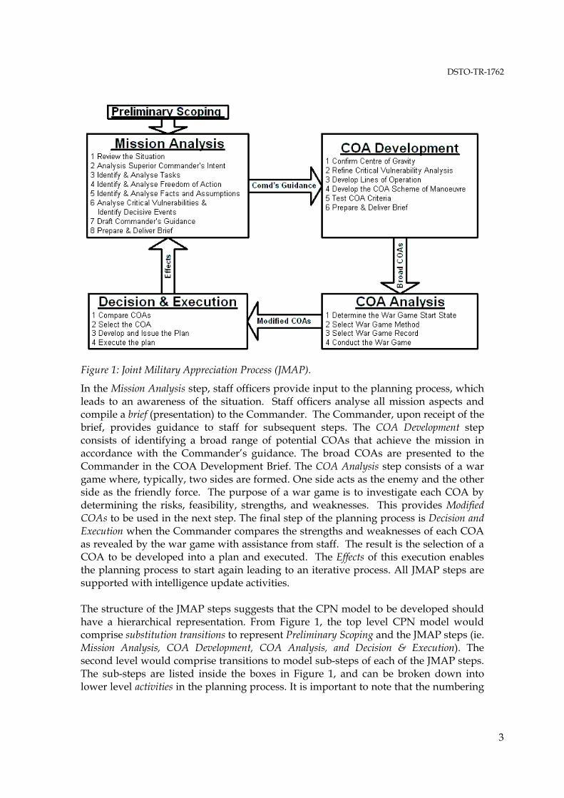
The JMAP is a logical decision-making process that guides military staff in producing an operational plan. It comprises four consecutive and iterative steps as illustrated in Figure 1: Mission Analysis, Course of Action (COA) Development, COA Analysis, and Decision and Execution. Prior to these four steps, Preliminary Scoping is normally conducted to analyse the superior HQ’s intent and guidance to gain an idea of the “bigger picture”.
DSTO-TR-1762
3
Figure 1: Joint Military Appreciation Process (JMAP).
In the Mission Analysis step, staff officers provide input to the planning process, which leads to an awareness of the situation. Staff officers analyse all mission aspects and compile a brief (presentation) to the Commander. The Commander, upon receipt of the brief, provides guidance to staff for subsequent steps. The COA Development step consists of identifying a broad range of potential COAs that achieve the mission in accordance with the Commander’s guidance. The broad COAs are presented to the Commander in the COA Development Brief. The COA Analysis step consists of a war game where, typically, two sides are formed. One side acts as the enemy and the other side as the friendly force. The purpose of a war game is to investigate each COA by determining the risks, feasibility, strengths, and weaknesses. This provides Modified COAs to be used in the next step. The final step of the planning process is Decision and Execution when the Commander compares the strengths and weaknesses of each COA as revealed by the war game with assistance from staff. The result is the selection of a COA to be developed into a plan and executed. The Effects of this execution enables the planning process to start again leading to an iterative process. All JMAP steps are supported with intelligence update activities. The structure of the JMAP steps suggests that the CPN model to be developed should have a hierarchical representation. From Figure 1, the top level CPN model would comprise substitution transitions to represent Preliminary Scoping and the JMAP steps (ie. Mission Analysis, COA Development, COA Analysis, and Decision & Execution). The second level would comprise transitions to model sub-steps of each of the JMAP steps. The sub-steps are listed inside the boxes in Figure 1, and can be broken down into lower level activities in the planning process. It is important to note that the numbering
DSTO-TR-1762
4
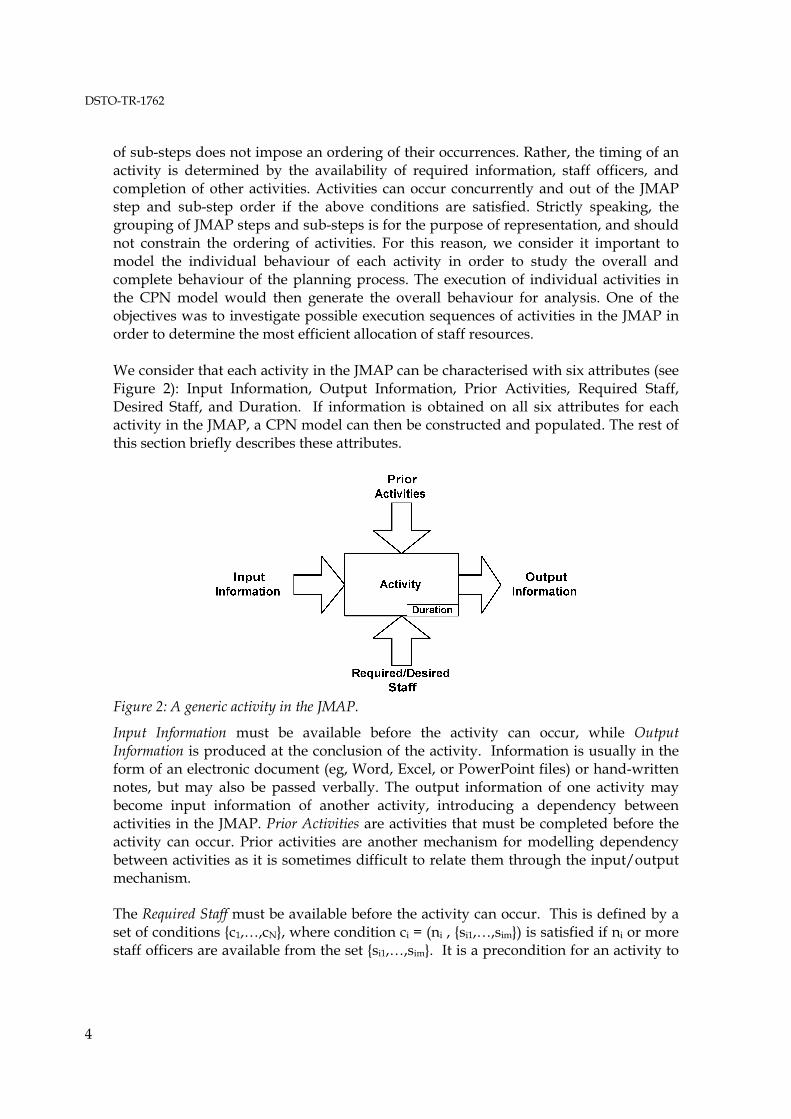
of sub-steps does not impose an ordering of their occurrences. Rather, the timing of an activity is determined by the availability of required information, staff officers, and completion of other activities. Activities can occur concurrently and out of the JMAP step and sub-step order if the above conditions are satisfied. Strictly speaking, the grouping of JMAP steps and sub-steps is for the purpose of representation, and should not constrain the ordering of activities. For this reason, we consider it important to model the individual behaviour of each activity in order to study the overall and complete behaviour of the planning process. The execution of individual activities in the CPN model would then generate the overall behaviour for analysis. One of the objectives was to investigate possible execution sequences of activities in the JMAP in order to determine the most efficient allocation of staff resources. We consider that each activity in the JMAP can be characterised with six attributes (see Figure 2): Input Information, Output Information, Prior Activities, Required Staff, Desired Staff, and Duration. If information is obtained on all six attributes for each activity in the JMAP, a CPN model can then be constructed and populated. The rest of this section briefly describes these attributes.
Figure 2: A generic activity in the JMAP.
Input Information must be available before the activity can occur, while Output Information is produced at the conclusion of the activity. Information is usually in the form of an electronic document (eg, Word, Excel, or PowerPoint files) or hand-written notes, but may also be passed verbally. The output information of one activity may become input information of another activity, introducing a dependency between activities in the JMAP. Prior Activities are activities that must be completed before the activity can occur. Prior activities are another mechanism for modelling dependency between activities as it is sometimes difficult to relate them through the input/output mechanism. The Required Staff must be available before the activity can occur. This is defined by a set of conditions {c1,…,cN}, where condition ci = (ni , {si1,…,sim}) is satisfied if ni or more staff officers are available from the set {si1,…,sim}. It is a precondition for an activity to
DSTO-TR-1762
5
start that all such conditions {c1,…,cN} for the activity are satisfied. Also, staff from a Desired Staff set can provide assistance in the activity or benefit from attending the activity. Desired staff officers attend the activity if they are available, but do not prevent the activity from occurring. Duration is the expected length of the activity in minutes. This deterministic time was based on the available documentation and estimates from staff officers of the HQ based on domain knowledge and experience.
3. Overview of CPN model
This section describes the hierarchical CPN model that has been constructed using the approach described in Section 2.
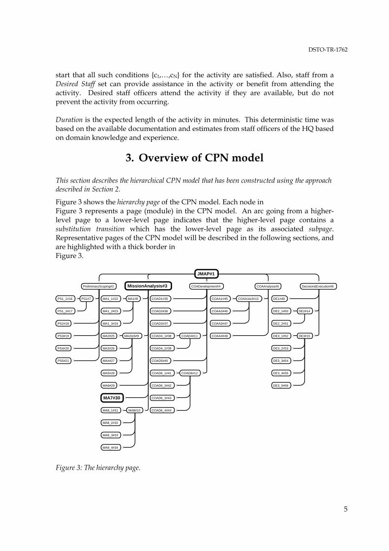
Figure 3 shows the hierarchy page of the CPN model. Each node in Figure 3 represents a page (module) in the CPN model. An arc going from a higher-level page to a lower-level page indicates that the higher-level page contains a substitution transition which has the lower-level page as its associated subpage. Representative pages of the CPN model will be described in the following sections, and are highlighted with a thick border in Figure 3.
Declaration#100
Hierarchy#10010
PreliminaryScoping#2 COAAnalysis#5 Decision&Execution#6COADevelopment#4
JMAP#1
MissionAnalysis#3
PS1_1#16
PS2#18
PS3#19
PS4#20
PS5#21
MA2to5#9
MA8#10
COAD6#12
COAA1to3#13
DE2#14
DE3#15
Stencil#58 M not I
MA1_1#22
MA2#25
MA3#26
MA4#27
MA5#28
MA6#29
MA7#30
MA8_1#31
MA8_2#32
MA8_3#33
COAD1#35
COAD2#36
COAD3#37
COAD4_1#38
COAD5#40
COAD6_1#41
COAD6_2#42
COAD6_3#43
COAA1#45
COAA4#48
COAA2#46
COAA3#47
DE1#49
DE2_1#50
DE2_2#51
DE3_1#52
DE3_2#53
DE3_3#54
DE3_4#55
DE3_5#56
StateSpace#63 M not I
COAD4#11
COAD4_2#39
MA1_2#23
MA1_3#24
MA1#8PS1#7
PS1_2#17
MA8_4#34
COAD6_4#44 Stencil2#61 M not I
NewPage#59 M not I
NewPage#60 M not I
NewPage#57
Figure 3: The hierarchy page.
DSTO-TR-1762
6
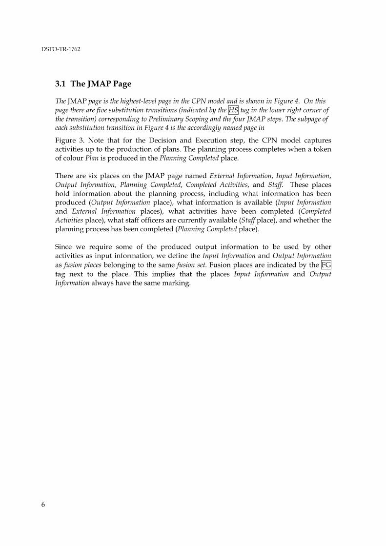
3.1 The JMAP Page
The JMAP page is the highest-level page in the CPN model and is shown in Figure 4. On this page there are five substitution transitions (indicated by the HS tag in the lower right corner of the transition) corresponding to Preliminary Scoping and the four JMAP steps. The subpage of each substitution transition in Figure 4 is the accordingly named page in
Figure 3. Note that for the Decision and Execution step, the CPN model captures activities up to the production of plans. The planning process completes when a token of colour Plan is produced in the Planning Completed place. There are six places on the JMAP page named External Information, Input Information, Output Information, Planning Completed, Completed Activities, and Staff. These places hold information about the planning process, including what information has been produced (Output Information place), what information is available (Input Information and External Information places), what activities have been completed (Completed Activities place), what staff officers are currently available (Staff place), and whether the planning process has been completed (Planning Completed place). Since we require some of the produced output information to be used by other activities as input information, we define the Input Information and Output Information as fusion places belonging to the same fusion set. Fusion places are indicated by the FG tag next to the place. This implies that the places Input Information and Output Information always have the same marking.
DSTO-TR-1762
7
COAAnalysis
HS
Preliminary Scoping
HS
Staff
StaffList
ms_to_list(Staff)
MissionAnalysis
HS
COADevelopment
HS
Decision &Execution
HS
InputInformation
InfoDoc
FG
CompletedActivities
InfoAct
ExternalInformation
InfoDoc
ExInfo
PlanningCompleted
InfoDoc
OutputInformation
InfoDoc
FG
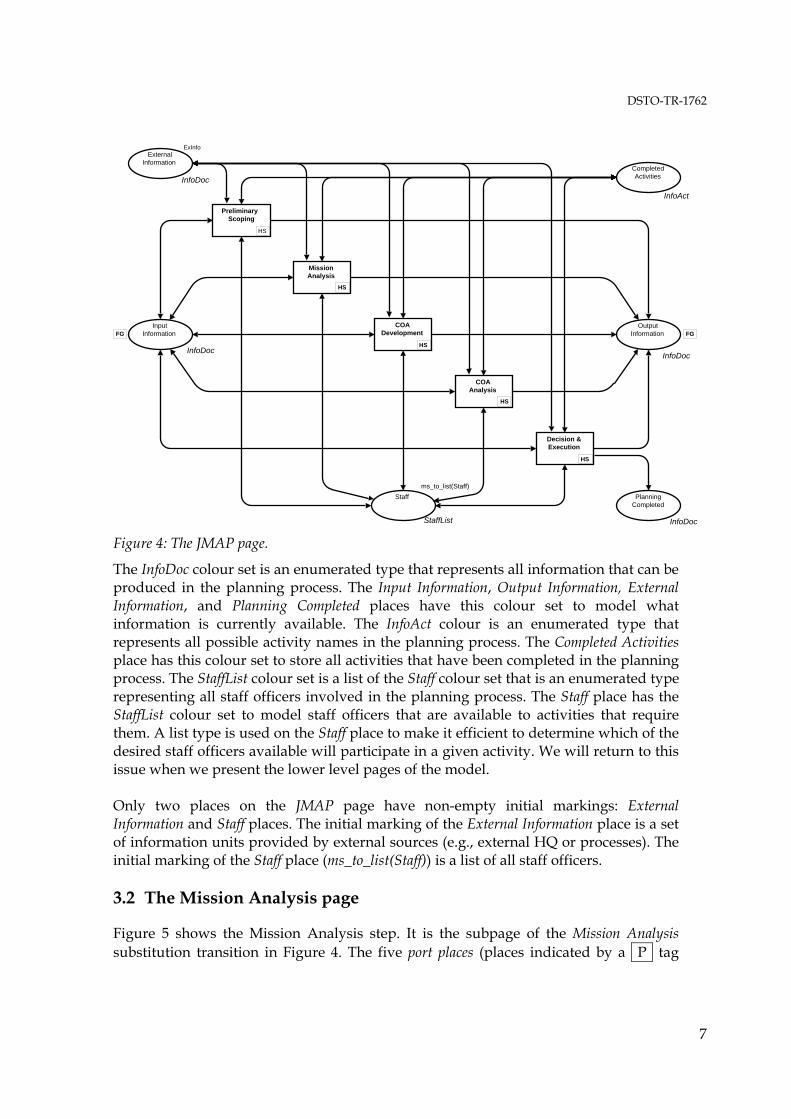
Figure 4: The JMAP page.
The InfoDoc colour set is an enumerated type that represents all information that can be produced in the planning process. The Input Information, Output Information, External Information, and Planning Completed places have this colour set to model what information is currently available. The InfoAct colour is an enumerated type that represents all possible activity names in the planning process. The Completed Activities place has this colour set to store all activities that have been completed in the planning process. The StaffList colour set is a list of the Staff colour set that is an enumerated type representing all staff officers involved in the planning process. The Staff place has the StaffList colour set to model staff officers that are available to activities that require them. A list type is used on the Staff place to make it efficient to determine which of the desired staff officers available will participate in a given activity. We will return to this issue when we present the lower level pages of the model. Only two places on the JMAP page have non-empty initial markings: External Information and Staff places. The initial marking of the External Information place is a set of information units provided by external sources (e.g., external HQ or processes). The initial marking of the Staff place (ms_to_list(Staff)) is a list of all staff officers. 3.2 The Mission Analysis page
Figure 5 shows the Mission Analysis step. It is the subpage of the Mission Analysis substitution transition in Figure 4. The five port places (places indicated by a P tag
DSTO-TR-1762
8
positioned next to the them) are connected to the accordingly named socket places in Figure 4. Port and socket places are the mechanism by which a subpage interfaces with the superpage containing the substitution transition. The marking of a port place is always the same as it corresponding socket place. See [7] for details.
Staff
StaffListP I/O
OutputInformation
InfoDoc
P Out
MA6Analyse CVs
& Identify DEsHS
InputInformation
InfoDoc
P I/O
MA2-5Analyse Mission
AspectsHS
MA8Prepare &
Deliver BriefHS
CompletedActivities
InfoAct
P I/O
MA1Review the
SituationHS
MA7Draft Comd’s
GuidanceHS
ExternalInformation
InfoDoc
P I/O
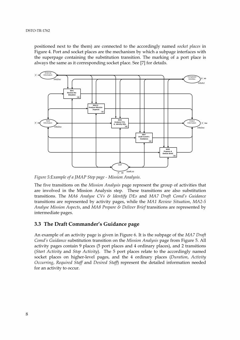
Figure 5:Example of a JMAP Step page - Mission Analysis.
The five transitions on the Mission Analysis page represent the group of activities that are involved in the Mission Analysis step. These transitions are also substitution transitions. The MA6 Analyse CVs & Identify DEs and MA7 Draft Comd’s Guidance transitions are represented by activity pages, while the MA1 Review Situation, MA2-5 Analyse Mission Aspects, and MA8 Prepare & Deliver Brief transitions are represented by intermediate pages. 3.3 The Draft Commander’s Guidance page
An example of an activity page is given in Figure 6. It is the subpage of the MA7 Draft Comd’s Guidance substitution transition on the Mission Analysis page from Figure 5. All activity pages contain 9 places (5 port places and 4 ordinary places), and 2 transitions (Start Activity and Stop Activity). The 5 port places relate to the accordingly named socket places on higher-level pages, and the 4 ordinary places (Duration, Activity Occurring, Required Staff and Desired Staff) represent the detailed information needed for an activity to occur.
DSTO-TR-1762
9
CompletedActivities
InfoAct
P I/O
Staff
StaffListP I/O
InputInformation
InfoDoc
P I/OOutput
Information
InfoDoc
P Out
ExternalInformation
InfoDoc
P I/O
Duration
Duration
1‘18
StartActivity
[ checkstaffenabled ( required, stafflist ) ]
StopActivity
ActivityOccurring
StaffList
RequiredStaff
ReqStaffList
JPG_Req
DesiredStaff
StaffList
JPG_Des
1‘Prelim_Guidance++1‘Proposed_DEs
1‘Proposed_Intent
1‘MA7
stafflist
duration
removestaff( required, desired, stafflist )
return_staff( staffused, stafflist )
stafflist
calcattendance( required, desired, stafflist )@+duration staffused
desired
required
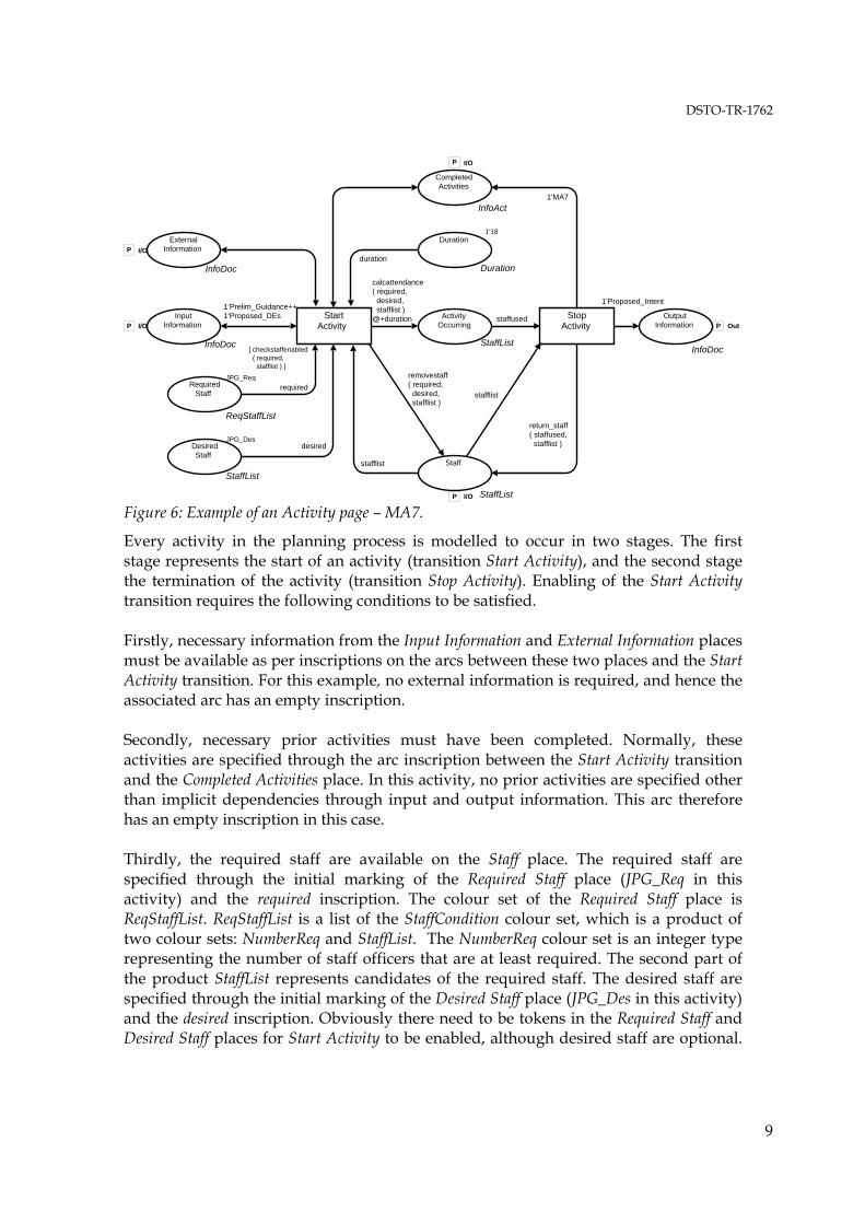
Figure 6: Example of an Activity page – MA7.
Every activity in the planning process is modelled to occur in two stages. The first stage represents the start of an activity (transition Start Activity), and the second stage the termination of the activity (transition Stop Activity). Enabling of the Start Activity transition requires the following conditions to be satisfied. Firstly, necessary information from the Input Information and External Information places must be available as per inscriptions on the arcs between these two places and the Start Activity transition. For this example, no external information is required, and hence the associated arc has an empty inscription. Secondly, necessary prior activities must have been completed. Normally, these activities are specified through the arc inscription between the Start Activity transition and the Completed Activities place. In this activity, no prior activities are specified other than implicit dependencies through input and output information. This arc therefore has an empty inscription in this case. Thirdly, the required staff are available on the Staff place. The required staff are specified through the initial marking of the Required Staff place (JPG_Req in this activity) and the required inscription. The colour set of the Required Staff place is ReqStaffList. ReqStaffList is a list of the StaffCondition colour set, which is a product of two colour sets: NumberReq and StaffList. The NumberReq colour set is an integer type representing the number of staff officers that are at least required. The second part of the product StaffList represents candidates of the required staff. The desired staff are specified through the initial marking of the Desired Staff place (JPG_Des in this activity) and the desired inscription. Obviously there need to be tokens in the Required Staff and Desired Staff places for Start Activity to be enabled, although desired staff are optional.
DSTO-TR-1762
10
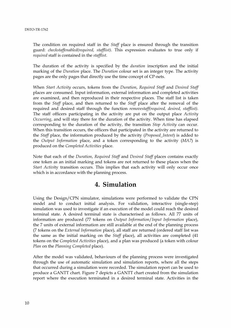
The condition on required staff in the Staff place is ensured through the transition guard: checkstaffenabled(required, stafflist). This expression evaluates to true only if required staff is contained in the stafflist. The duration of the activity is specified by the duration inscription and the initial marking of the Duration place. The Duration colour set is an integer type. The activity pages are the only pages that directly use the time concept of CP-nets. When Start Activity occurs, tokens from the Duration, Required Staff and Desired Staff places are consumed. Input information, external information and completed activities are examined, and then reproduced in their respective places. The staff list is taken from the Staff place, and then returned to the Staff place after the removal of the required and desired staff through the function removestaff(required, desired, stafflist). The staff officers participating in the activity are put on the output place Activity Occurring, and will stay there for the duration of the activity. When time has elapsed corresponding to the duration of the activity, the transition Stop Activity can occur. When this transition occurs, the officers that participated in the activity are returned to the Staff place, the information produced by the activity (Proposed_Intent) is added to the Output Information place, and a token corresponding to the activity (MA7) is produced on the Completed Activities place. Note that each of the Duration, Required Staff and Desired Staff places contains exactly one token as an initial marking and tokens are not returned to these places when the Start Activity transition occurs. This implies that each activity will only occur once which is in accordance with the planning process.
4. Simulation
Using the Design/CPN simulator, simulations were performed to validate the CPN model and to conduct initial analysis. For validation, interactive (single-step) simulation was used to investigate if an execution of the model could reach the desired terminal state. A desired terminal state is characterised as follows. All 77 units of information are produced (77 tokens on Output Information/Input Information place), the 7 units of external information are still available at the end of the planning process (7 tokens on the External Information place), all staff are returned (ordered staff list was the same as the initial marking on the Staff place), all activities are completed (41 tokens on the Completed Activities place), and a plan was produced (a token with colour Plan on the Planning Completed place). After the model was validated, behaviours of the planning process were investigated through the use of automatic simulation and simulation reports, where all the steps that occurred during a simulation were recorded. The simulation report can be used to produce a GANTT chart. Figure 7 depicts a GANTT chart created from the simulation report where the execution terminated in a desired terminal state. Activities in the

DSTO-TR-1762
11
JMAP are shown on the y-axis, and time (in minutes) is on the x-axis. The planning process took 2095 minutes to complete. It can be noted that the planning process is very sequential in nature, yet some activities have occurred simultaneously and out of the order of the JMAP steps. For example, some Preliminary Scoping activities (PS1_1, PS1_2 and PS2) occurred simultaneously, and some other Preliminary Scoping activities PS4 and PS5 occurred after certain Mission Analysis activities (labels starting with MA). These kinds of properties make the planning process more flexible and therefore a plan could be produced quicker than a strictly sequential planning process that would take 2151 minutes. The CPN model allows activities to occur “out of sequence” according to the activity attributes.
0 200 400 600 800 1000 1200 1400 1600 1800 2000 2200
PS1_1PS1_2
PS2PS3
MA1_1MA1_2
MA6MA2MA7MA5MA4MA3
MA8_1PS4PS5
MA1_3MA8_2MA8_3MA8_4
COAD1COAD3
COAD4_1COAD4_2
COAD5COAD2
COAD6_1COAD6_2COAD6_3COAD6_4
COAA2COAA3COAA1COAA4
DE1DE2_1DE2_2DE3_1DE3_2DE3_3DE3_4DE3_5
Act
ivity
Time Figure 7: GANTT chart extracted from an automatic simulation.
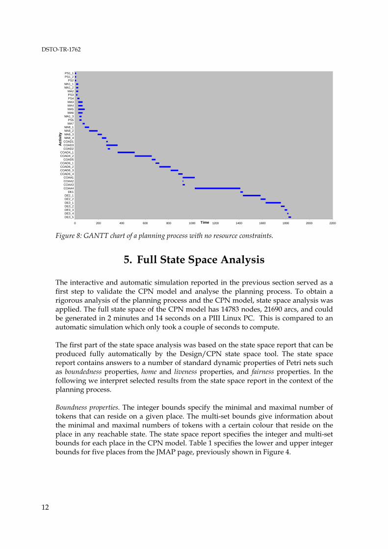
We also investigated the completion time of the planning process when there were no resource requirements, ie., the planning process was based solely on information flow with staff requirements ignored. A simulation report of this model was produced, and the corresponding GANTT chart is shown in Figure 8. From the GANTT chart, we found that the planning process took 1845 minutes to complete when there are no resource constraints. A larger number of activities were shown to have occurred concurrently. For example, certain Mission Analysis activities (MA3, MA4, MA5, and MA6) occurred in parallel. The simulation results suggest that one method of improving the planning process efficiency is to enable concurrent activities through de-conflicting staff requirements on activities.
DSTO-TR-1762
12
0 200 400 600 800 1000 1200 1400 1600 1800 2000 2200
PS1_1PS1_2
PS2MA1_1MA1_2
MA2PS3PS4MA3MA4MA5MA6
MA1_3PS5MA7
MA8_1MA8_2MA8_3MA8_4
COAD1COAD3COAD2
COAD4_1COAD4_2
COAD5COAD6_1COAD6_2COAD6_3COAD6_4
COAA1COAA2COAA3COAA4
DE1DE2_1DE2_2DE3_1DE3_2DE3_3DE3_4DE3_5
Act
ivity
Time Figure 8: GANTT chart of a planning process with no resource constraints.
5. Full State Space Analysis
The interactive and automatic simulation reported in the previous section served as a first step to validate the CPN model and analyse the planning process. To obtain a rigorous analysis of the planning process and the CPN model, state space analysis was applied. The full state space of the CPN model has 14783 nodes, 21690 arcs, and could be generated in 2 minutes and 14 seconds on a PIII Linux PC. This is compared to an automatic simulation which only took a couple of seconds to compute. The first part of the state space analysis was based on the state space report that can be produced fully automatically by the Design/CPN state space tool. The state space report contains answers to a number of standard dynamic properties of Petri nets such as boundedness properties, home and liveness properties, and fairness properties. In the following we interpret selected results from the state space report in the context of the planning process. Boundness properties. The integer bounds specify the minimal and maximal number of tokens that can reside on a given place. The multi-set bounds give information about the minimal and maximal numbers of tokens with a certain colour that reside on the place in any reachable state. The state space report specifies the integer and multi-set bounds for each place in the CPN model. Table 1 specifies the lower and upper integer bounds for five places from the JMAP page, previously shown in Figure 4.
DSTO-TR-1762
13
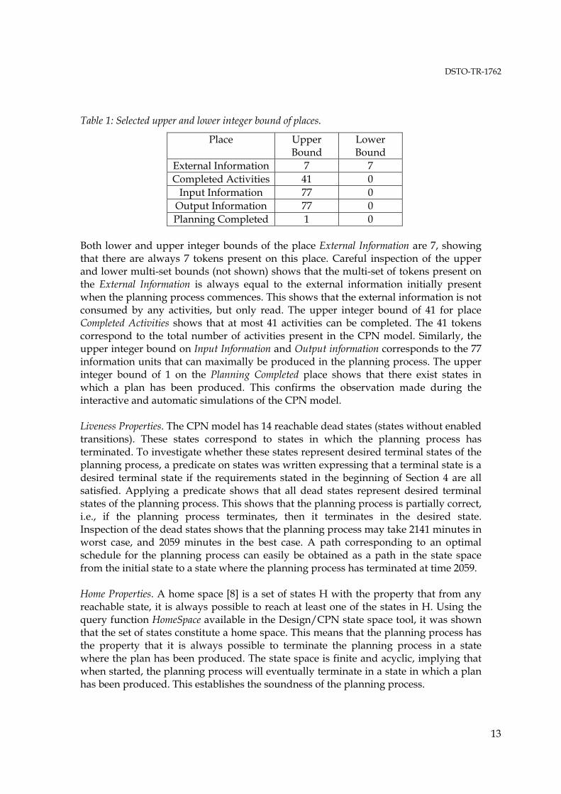
Table 1: Selected upper and lower integer bound of places.
Place Upper Bound
Lower Bound
External Information 7 7 Completed Activities 41 0
Input Information 77 0 Output Information 77 0 Planning Completed 1 0
Both lower and upper integer bounds of the place External Information are 7, showing that there are always 7 tokens present on this place. Careful inspection of the upper and lower multi-set bounds (not shown) shows that the multi-set of tokens present on the External Information is always equal to the external information initially present when the planning process commences. This shows that the external information is not consumed by any activities, but only read. The upper integer bound of 41 for place Completed Activities shows that at most 41 activities can be completed. The 41 tokens correspond to the total number of activities present in the CPN model. Similarly, the upper integer bound on Input Information and Output information corresponds to the 77 information units that can maximally be produced in the planning process. The upper integer bound of 1 on the Planning Completed place shows that there exist states in which a plan has been produced. This confirms the observation made during the interactive and automatic simulations of the CPN model. Liveness Properties. The CPN model has 14 reachable dead states (states without enabled transitions). These states correspond to states in which the planning process has terminated. To investigate whether these states represent desired terminal states of the planning process, a predicate on states was written expressing that a terminal state is a desired terminal state if the requirements stated in the beginning of Section 4 are all satisfied. Applying a predicate shows that all dead states represent desired terminal states of the planning process. This shows that the planning process is partially correct, i.e., if the planning process terminates, then it terminates in the desired state. Inspection of the dead states shows that the planning process may take 2141 minutes in worst case, and 2059 minutes in the best case. A path corresponding to an optimal schedule for the planning process can easily be obtained as a path in the state space from the initial state to a state where the planning process has terminated at time 2059. Home Properties. A home space [8] is a set of states H with the property that from any reachable state, it is always possible to reach at least one of the states in H. Using the query function HomeSpace available in the Design/CPN state space tool, it was shown that the set of states constitute a home space. This means that the planning process has the property that it is always possible to terminate the planning process in a state where the plan has been produced. The state space is finite and acyclic, implying that when started, the planning process will eventually terminate in a state in which a plan has been produced. This establishes the soundness of the planning process.
DSTO-TR-1762
14
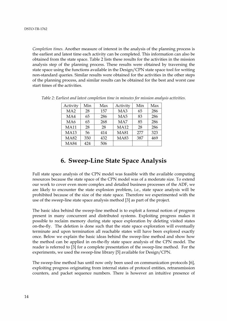
Completion times. Another measure of interest in the analysis of the planning process is the earliest and latest time each activity can be completed. This information can also be obtained from the state space. Table 2 lists these results for the activities in the mission analysis step of the planning process. These results were obtained by traversing the state space using the functions available in the Design/CPN state space tool for writing non-standard queries. Similar results were obtained for the activities in the other steps of the planning process, and similar results can be obtained for the best and worst case start times of the activities.
Table 2: Earliest and latest completion time in minutes for mission analysis activities.
Activity Min Max Activity Min Max MA2 28 157 MA3 65 286 MA4 65 286 MA5 83 286 MA6 65 268 MA7 85 286
MA11 28 28 MA12 28 286 MA13 56 414 MA81 277 323 MA82 350 432 MA83 387 469 MA84 424 506
6. Sweep-Line State Space Analysis
Full state space analysis of the CPN model was feasible with the available computing resources because the state space of the CPN model was of a moderate size. To extend our work to cover even more complex and detailed business processes of the ADF, we are likely to encounter the state explosion problem, i.e., state space analysis will be prohibited because of the size of the state space. Therefore we experimented with the use of the sweep-line state space analysis method [3] as part of the project. The basic idea behind the sweep-line method is to exploit a formal notion of progress present in many concurrent and distributed systems. Exploiting progress makes it possible to reclaim memory during state space exploration by deleting visited states on-the-fly. The deletion is done such that the state space exploration will eventually terminate and upon termination all reachable states will have been explored exactly once. Below we explain the basic ideas behind the sweep-line method and show how the method can be applied in on-the-fly state space analysis of the CPN model. The reader is referred to [3] for a complete presentation of the sweep-line method. For the experiments, we used the sweep-line library [5] available for Design/CPN. The sweep-line method has until now only been used on communication protocols [6], exploiting progress originating from internal states of protocol entities, retransmission counters, and packet sequence numbers. There is however an intuitive presence of
DSTO-TR-1762
15
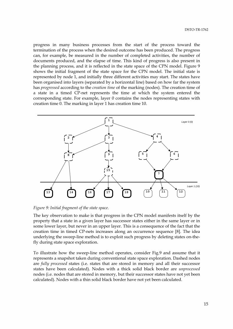
progress in many business processes from the start of the process toward the termination of the process when the desired outcome has been produced. The progress can, for example, be measured in the number of completed activities, the number of documents produced, and the elapse of time. This kind of progress is also present in the planning process, and it is reflected in the state space of the CPN model. Figure 9 shows the initial fragment of the state space for the CPN model. The initial state is represented by node 1, and initially three different activities may start. The states have been organised into layers (separated by a horizontal line) based on how far the system has progressed according to the creation time of the marking (nodes). The creation time of a state in a timed CP-net represents the time at which the system entered the corresponding state. For example, layer 0 contains the nodes representing states with creation time 0. The marking in layer 1 has creation time 10.
1
2 3 4
8 9 5 6
13 14
157
16 17 18 10 11 12
Layer 0 (0)
Layer 1 (10)
Figure 9: Initial fragment of the state space.
The key observation to make is that progress in the CPN model manifests itself by the property that a state in a given layer has successor states either in the same layer or in some lower layer, but never in an upper layer. This is a consequence of the fact that the creation time in timed CP-nets increases along an occurrence sequence [8]. The idea underlying the sweep-line method is to exploit such progress by deleting states on-the-fly during state space exploration. To illustrate how the sweep-line method operates, consider Fig.9 and assume that it represents a snapshot taken during conventional state space exploration. Dashed nodes are fully processed states (i.e. states that are stored in memory and all their successor states have been calculated). Nodes with a thick solid black border are unprocessed nodes (i.e. nodes that are stored in memory, but their successor states have not yet been calculated). Nodes with a thin solid black border have not yet been calculated.
DSTO-TR-1762
16
If the state space exploration algorithm processes states according to their creation time, node 7 will be the state among the unprocessed states that will be selected for processing next. This will add nodes 10, 11, and 12 to the set of stored states and mark these as unprocessed. At this point it can be observed that it is not possible from any of the unprocessed states to reach one of the markings 1-9 or 15. The reason is these nodes represent states where the planning process has not progressed as far as in any of the unprocessed states. Hence, it is safe to delete these nodes, as they cannot possibly be needed for comparison with newly generated states when checking (during the state space exploration) whether a state has already been visited. In a similar way, once all the states in the second layer have been fully processed these nodes can be deleted from the set of nodes stored in memory. Intuitively, one can think of a sweep-line as being aligned with the highest layer (seen from the top) that contains unprocessed states. During state space exploration, unprocessed states are selected for processing in a least-progress first order causing the sweep-line to move downwards. States will thereby be added in front of the sweep-line and deleted behind the sweep-line. We could have subdivided each layer further by taking into account, e.g., the number of started and completed activities or the number of produced documents. To use the sweep-line method as implemented in the Design/CPN library [5], a progress measure must be provided to the tool. The progress measure specifies the progress to be exploited by the sweep-line method, and consists of a mapping from states into progress values. The progress value of a state quantifies the progress of the system in that state. The progress mapping is required to preserve the reachability relation of the CPN model, i.e., a successor state S' of a state S is required to have the same or a higher progress value than S. For the CPN model of the planning process, we used a function that maps a state into its creation time. As an inherited property of timed CP-nets, this mapping preserves the reachability relation. The peak number of states stored with the sweep-line method using a progress measure based on creation time is 2149 nodes. Assuming that memory consumption is linear in the number of states stored, this corresponds to a reduction in peak memory consumption for analysis to 11.8%. The total time used to conduct the sweep of the state space was 2 minutes and 33 seconds. Using the sweep-line method, we can investigate the same dynamic properties as were considered in the previous section using the query functions available in the sweep-line library. The main difference is that analysis is now done on-the-fly during the state space exploration. This is necessary since state information is deleted by the sweep-line method. The sweep-line method can be used to reason about home and liveness properties because states in a strongly connected component of the state space will have the same progress value and hence will be present in memory simultaneously before being deleted.
DSTO-TR-1762
17
7. Conclusions and Future Work
We have presented the development of a CPN model of a planning process used in an operational headquarters (HQ). The model gives a formal and graphical representation of the planning process. It captures activities in the planning process, and how staff and information flow between these activities. An important feature of the CPN model is the structured modelling of activities which eased the development of the CPN model based on the JMAP and SOP documents. The CPN model is useful for training new staff officers, assisting the HQ in modifying existing planning documentation based on the JMAP, and providing a framework to test variations of the JMAP and other business processes. Another contribution of this report is the analysis of the planning process using simulation and state spaces. The simulation results allowed recommendations to be given to the HQ to facilitate concurrent activities in the planning process, and hence an earlier completed plan. The state space analysis allowed the soundness of the planning process to be established together with additional quantitative properties. To alleviate the state explosion problem, we have reported on initial experiments with the application of the sweep-line method in the workflow domain. These experimental results are very encouraging for the use of the sweep-line method in this domain, where models typically have an inherited presence of progress that can be exploited. Future directions for such work could include extension of the CPN model to represent the external JMAP processes and other related processes at the HQ that interact with the JMAP. Also, it would be of interest to refine the CPN model by replacing the deterministic duration of activities with time intervals. The work on Interval Timed Coloured Petri nets and their state space analysis [2, 17] could serve as a starting point for this work. The CPN model could also be applied at the HQ for training staff, and as a tool for monitoring the planning process during a planning exercise. In such a setting, the progress of the planning process can be monitored, and state space analysis can be used to make predictions, e.g., about worst and best case termination time given the current state of the planning process.
DSTO-TR-1762
18
References 1. Australian Defence Force Publications (ADFP). Joint Military Appreciation Process.
Operations Series 9, Joint Planning, Chapter 8, 1999. 2. G. Bertholot. Occurrence Graphs for Interval Timed Coloured Petri Nets. In Proc.
Of ICATPN’94, volume 815 of Lecture Notes in Computer Science, pp. 79-98. Springer-Verlag, 1994.
3. S. Christensen, L.M. Kristensen, and T. Mailund. A Sweep-Line Method for State Space Exploration. In Proceedings of TACAS'2001, volume 2031 of Lecture Notes in Computer Science, pp. 450-464. Springer Verlag, 2001.
4. Design/CPN Online. http://www.daimi.au.dk/designCPN/. 5. G. E. Gallasch, L. M. Kristensen, and T. Mailund. The Sweep/CPN Library.
Available via http://www.daimi.au.dk/designCPN/libs/sweepcpn/ 6. S. Gordon, L.M. Kristensen, and J. Billington. Verification of a Revised WAP
Wireless Transaction Protocol. In Proceedings of Petri Nets 2002, volume 2360 of Lecture Notes in Computer Science, pp.182-202. Springer-Verlag, 2002.
7. K. Jensen. Coloured Petri Nets: Volume 1: Basic Concepts Monographs in Theoretical Computer Science, Spinger-Verlag, 1997.
8. K. Jensen. Coloured Petri Nets: Volume 2: Analysis Methods Monographs in Theoretical Computer Science, Spinger-Verlag, 1994.
9. K. Jensen. Coloured Petri Nets: Volume 3: Practical Use. Monographs in Theoretical Computer Science, Spinger-Verlag, 1997.
10. L. M. Kristensen, S. Christensen, and K. Jensen. The Practitioner’s Guide to Coloured Petri Nets. International Journal on Software Tools for Technology Transfer, 2(2):98-132, 1998.
11. L. M. Kristensen, B. Mitchell, L. Zhang, and J. Billington. Modelling and Initial Analysis of Operational Planning Processes using Coloured Petri nets. In proceedings of Workshop on Formal Methods Applied to Defence Systems, volume 12 in Conferences in Research and Practice in Information Technology, pp. 105-114. Australian Computer Society, 2002.
12. S. Lumsden, R. Smallwood, B. Mitchell, and L. Zhang. Modelling Operational Level Planning Processes with Coloured Petri Nets. 7th International Command and Control Research and Technology Symposium. 2002.
13. T. Murata. Petri Nets: Properties, Analysis, and Application. In Proceedings of the IEEE, Vol. 77. No. 4, pp. 541-580. IEEE Computer Society, 1989.
14. A. Valmari. The State Explosion Problem. Lectures on Petri Nets I: Basic Models. Volume 1491 of Lecture Notes in Computer Science, pp. 429-528. Springer-Verlag, 1998.
15. W. van der Aalst and K. van Hee. Workflow Management – Models, Methods and Systems. The MIT Press, 2002.
16. V. van der Aalst. Advanced Tutorial on Workflow Management. 23rd International Conference on Application and Theory of Petri Nets, Adelaide, June 2002.
17. V. van der Aalst. Interval Timed Coloured Petri Nets and Their Analysis. In Proc. Of ICATPN’93, volume 691 of Lecture Notes in Computer Science, pp. 453-472. Springer-Verlag, 1993.

DISTRIBUTION LIST
Formal Specification and State Space Analysis of an Operational Planning Process
Brice Mitchell, Lars Michael Kristensen and Lin Zhang
AUSTRALIA
DEFENCE ORGANISATION Task Sponsor
COFS DJFHQ (DJFHQ Gallipoli Barracks Enoggera QLD 4052) 1 printed CI ADFWC (RAAF Base Williamtown NSW 2314) 1 printed
S&T Program
Chief Defence Scientist 1 Deputy Chief Defence Scientist (Policy) 1 AS Science Corporate Management 1 Director General Science Policy Development Counsellor Defence Science, London Doc Data Sheet Counsellor Defence Science, Washington Doc Data Sheet Scientific Adviser to MRDC, Thailand Doc Data Sheet Scientific Adviser Joint 1 Navy Scientific Adviser Doc Data Sheet Scientific Adviser – Army Doc Data Sheet Air Force Scientific Adviser Doc Data Sheet Scientific Adviser to the DMO Doc Data Sheet
Director Platforms Science Laboratory (Corporate Leader Air) Doc Data Sheet & Exec Summary Information Sciences Laboratory
Chief Command & Control Division Doc Data Sheet Research Leader Command Decision Environments Branch 1 Research Leader Information Enterprises Branch 1 Research Leader Joint Command Analysis Branch 1 Research Leader Intelligence Information Branch Doc Data Sheet Head Human Systems Integration Doc Data Sheet Head Information Exploitation Doc Data Sheet Head Effects-Based Modelling and Analysis 1 printed Head Information Systems Doc Data Sheet Head Distributed Enterprises Doc Data Sheet Head Joint Operations Analysis and Support 1 Head Command Concepts and Architectures Doc Data Sheet Head Command Process Integration and Analysis 1 Head Intelligence Analysis Doc Data Sheet Publications and Publicity Officer, C2D/EOC2D shared copy Dr Karyn I’Anson 1 printed Dr Ken Skinner (DJFHQ Gallipoli Barracks Enogerra QLD 4052) 1 printed
Authors: Mr Brice Mitchell 1 printed Dr Lin Zhang 1 printed Assistant Professor Lars Michael Kristensen, 1 printed
Department of Computer Science, University of Aarhus, IT-parken, Aabogade 34, DK-8200 Aarhus N, Denmark DSTO Library and Archives
Library Edinburgh 1 Defence Archives 1
Capability Development Group
Director General Maritime Development Doc Data Sheet Director General Land Development 1 Director General Capability and Plans Doc Data Sheet Assistant Secretary Investment Analysis Doc Data Sheet Director Capability Plans and Programming Doc Data Sheet Director General Australian Defence Simulation Office Doc Data Sheet
Chief Information Officer Group
Director General Australian Defence Simulation Office Doc Data Sheet AS Information Strategy and Futures Doc Data Sheet Director General Information Services Doc Data Sheet
Strategy Group
Director General Military Strategy Doc Data Sheet Assistant Secretary Governance and Counter-Proliferation Doc Data Sheet
Navy Maritime Operational Analysis Centre, Doc Data Sht & Dist List Building 89/90 Garden Island, Sydney NSW shared copy
Deputy Director (Operations) Deputy Director (Analysis) Director General Navy Capability, Performance and Plans, Doc Data Sheet
Navy Headquarters Director General Navy Strategic Policy and Futures, Doc Data Sheet
Navy Headquarters Air Force
SO (Science) - Headquarters Air Combat Group, Doc Data Sht & Exec Sum RAAF Base, Williamtown, NSW 2314
Army
ABCA National Standardisation Officer, e-mailed Doc Data Land Warfare Development Sector, Puckapunyal VIC sheet
SO (Science) - Land Headquarters (LHQ), Doc Data Sht & Exec Sum Victoria Barracks NSW SO (Science), Deployable Joint Force Headquarters (DJFHQ) (L), Doc Data Sheet Enoggera QLD
}

Joint Operations Command Director General Joint Operations Doc Data Sheet Chief of Staff Headquarters Joint Operations Command Doc Data Sheet Commandant ADF Warfare Centre Doc Data Sheet Director General Strategic Logistics Doc Data Sheet COS Australian Defence College Doc Data Sheet
Intelligence and Security Group
AS Concepts, Capability and Resources 1 DGSTA Defence Intelligence Organisation 1 printed Manager, Information Centre, Defence Intelligence Organisation 1 Director Advanced Capabilities Doc Data Sheet
Defence Materiel Organisation
Deputy CEO Doc Data Sheet Head Aerospace Systems Division Doc Data Sheet Head Maritime Systems Division Doc Data Sheet Program Manager Air Warfare Destroyer Doc Data Sheet CDR Joint Logistics Command Doc Data Sheet
OTHER ORGANISATIONS
National Library of Australia 1 NASA (Canberra) 1
UNIVERSITIES AND COLLEGES
Australian Defence Force Academy Library 1 Head of Aerospace and Mechanical Engineering 1
Serials Section (M list), Deakin University Library, Geelong, VIC 1 Hargrave Library, Monash University Doc Data Sheet Librarian, Flinders University 1 Professor Jonathan Billington (University of South Australia) 1
OUTSIDE AUSTRALIA
INTERNATIONAL DEFENCE INFORMATION CENTRES US Defense Technical Information Center 1 UK Dstl Knowledge Services 1 Canada Defence Research Directorate R&D, 1
Knowledge & Information Management (DRDKIM) NZ Defence Information Centre 1
ABSTRACTING AND INFORMATION ORGANISATIONS
Library, Chemical Abstracts Reference Service 1 Engineering Societies Library, US 1 Materials Information, Cambridge Scientific Abstracts, US 1 Documents Librarian, The Center for Research Libraries, US 1
SPARES 5 printed Total number of copies: Printed 14 PDF 29 = 43

Page classification: UNCLASSIFIED
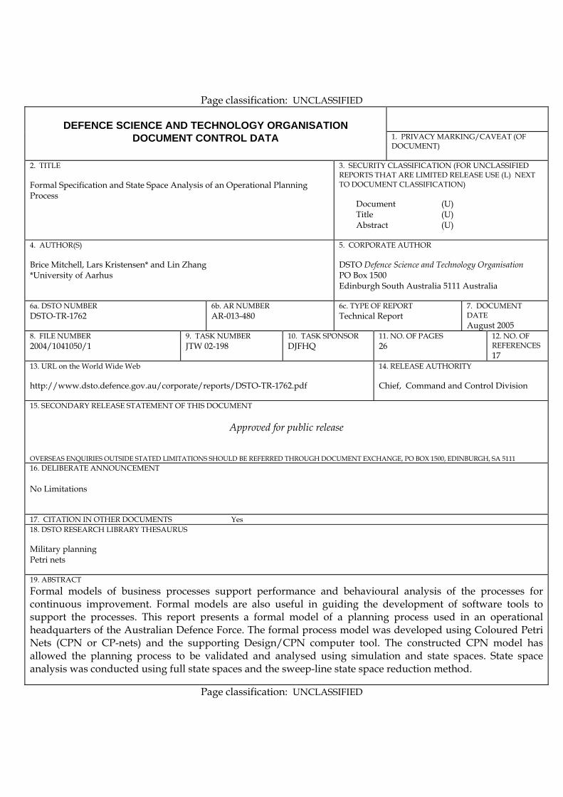
DEFENCE SCIENCE AND TECHNOLOGY ORGANISATION
DOCUMENT CONTROL DATA 1. PRIVACY MARKING/CAVEAT (OF DOCUMENT)
2. TITLE Formal Specification and State Space Analysis of an Operational Planning Process
3. SECURITY CLASSIFICATION (FOR UNCLASSIFIED REPORTS THAT ARE LIMITED RELEASE USE (L) NEXT TO DOCUMENT CLASSIFICATION) Document (U) Title (U) Abstract (U)
4. AUTHOR(S) Brice Mitchell, Lars Kristensen* and Lin Zhang *University of Aarhus
5. CORPORATE AUTHOR DSTO Defence Science and Technology Organisation PO Box 1500 Edinburgh South Australia 5111 Australia
6a. DSTO NUMBER DSTO-TR-1762
6b. AR NUMBER AR-013-480
6c. TYPE OF REPORT Technical Report
7. DOCUMENT DATE August 2005
8. FILE NUMBER 2004/1041050/1
9. TASK NUMBER JTW 02-198
10. TASK SPONSOR DJFHQ
11. NO. OF PAGES 26
12. NO. OF REFERENCES 17
13. URL on the World Wide Web http://www.dsto.defence.gov.au/corporate/reports/DSTO-TR-1762.pdf
14. RELEASE AUTHORITY Chief, Command and Control Division
15. SECONDARY RELEASE STATEMENT OF THIS DOCUMENT
Approved for public release OVERSEAS ENQUIRIES OUTSIDE STATED LIMITATIONS SHOULD BE REFERRED THROUGH DOCUMENT EXCHANGE, PO BOX 1500, EDINBURGH, SA 5111 16. DELIBERATE ANNOUNCEMENT No Limitations 17. CITATION IN OTHER DOCUMENTS Yes 18. DSTO RESEARCH LIBRARY THESAURUS Military planning Petri nets 19. ABSTRACT Formal models of business processes support performance and behavioural analysis of the processes for continuous improvement. Formal models are also useful in guiding the development of software tools to support the processes. This report presents a formal model of a planning process used in an operational headquarters of the Australian Defence Force. The formal process model was developed using Coloured Petri Nets (CPN or CP-nets) and the supporting Design/CPN computer tool. The constructed CPN model has allowed the planning process to be validated and analysed using simulation and state spaces. State space analysis was conducted using full state spaces and the sweep-line state space reduction method.
Page classification: UNCLASSIFIED