Formal Methods in Testing Software Architectures
26
Formal Methods in Testing Software Architectures Antonia Bertolino 1 , Paola Inverardi 2 , and Henry Muccini 2 1 Istituto di Scienza e Tecnologie dell’Informazione “A. Faedo” (ISTI-CNR), Area della Ricerca CNR di Pisa, 56100 Pisa, Italy [email protected] 2 Dipartimento di Informatica, Universit´ a dell’Aquila, Via Vetoio 1, 67100 L’Aquila, Italy [muccini,inverard]@di.univaq.it Abstract. SAs provide a high-level model of large, complex systems using suitable abstractions of the system components and their interac- tions. SA dynamic descriptions can be usefully employed in testing and analysis. We describe here an approach for SA-based conformance test- ing: architectural tests are selected from a Labelled Transition System (LTS) representing the SA behavior and are then refined into concrete tests to be executed on the implemented system. To identify the test se- quences, we derive abstract views of the LTS, called the ALTSs, to focus on relevant classes of architectural behaviors and hide away uninterest- ing interactions. The SA description of a Collaborative Writing system is used as an example of application. We also briefly discuss the relation of our approach with some recent research in exploiting the standard UML notation as an Architectural Description Language, and in conformance testing of reactive systems. 1 Introduction Software testing consists of the dynamic verification of a program’s behavior, performed by observing its execution on a selected set of test cases [5]. Depending on the strategy adopted for test selection, and on the notation and technologies employed in development, testing can take myriads of forms. Traditionally, software testing was mostly a manual, error-prone and expen- sive process, whose importance in achieving quality was underestimated. Re- cently, however, more emphasis is given to this phase, and more rigorous and automated approaches are sought. In particular, as opposed to ad-hoc derivation of test cases based on the tester’s intuition, the highly greater value of systematic derivation of test cases from a model of the system (model-based testing) is now generally recognized. Conformance testing checks that an implementation fulfills its specifications, and a suite of black-box tests is executed in an attempt to “capture” all and only
-
Upload
softwarecentral -
Category
Documents
-
view
766 -
download
0
description
Transcript of Formal Methods in Testing Software Architectures

Formal Methods in Testing SoftwareArchitectures
Antonia Bertolino1, Paola Inverardi2, and Henry Muccini2
1 Istituto di Scienza e Tecnologie dell’Informazione “A. Faedo” (ISTI-CNR),Area della Ricerca CNR di Pisa,
56100 Pisa, [email protected]
2 Dipartimento di Informatica, Universita dell’Aquila,Via Vetoio 1,
67100 L’Aquila, Italy[muccini,inverard]@di.univaq.it
Abstract. SAs provide a high-level model of large, complex systemsusing suitable abstractions of the system components and their interac-tions. SA dynamic descriptions can be usefully employed in testing andanalysis. We describe here an approach for SA-based conformance test-ing: architectural tests are selected from a Labelled Transition System(LTS) representing the SA behavior and are then refined into concretetests to be executed on the implemented system. To identify the test se-quences, we derive abstract views of the LTS, called the ALTSs, to focuson relevant classes of architectural behaviors and hide away uninterest-ing interactions. The SA description of a Collaborative Writing system isused as an example of application. We also briefly discuss the relation ofour approach with some recent research in exploiting the standard UMLnotation as an Architectural Description Language, and in conformancetesting of reactive systems.
1 Introduction
Software testing consists of the dynamic verification of a program’s behavior,performed by observing its execution on a selected set of test cases [5]. Dependingon the strategy adopted for test selection, and on the notation and technologiesemployed in development, testing can take myriads of forms.
Traditionally, software testing was mostly a manual, error-prone and expen-sive process, whose importance in achieving quality was underestimated. Re-cently, however, more emphasis is given to this phase, and more rigorous andautomated approaches are sought. In particular, as opposed to ad-hoc derivationof test cases based on the tester’s intuition, the highly greater value of systematicderivation of test cases from a model of the system (model-based testing) is nowgenerally recognized.
Conformance testing checks that an implementation fulfills its specifications,and a suite of black-box tests is executed in an attempt to “capture” all and only
2 Bertolino et al.
the relevant behaviors. The usage of formal methods in software development wasinitially advocated in the specification and design stages, to allow for the formalverification of system properties, and for supporting formal refinement alongthe subsequent development steps. However, as several recent studies suggest(e.g., [18, 43, 44, 28]), formal methods can be also advantageously employed inconformance testing, allowing for the systematic and automated synthesis of testcases from a system’s formal model.
For large, complex systems, the testing task is usually organized into stages,i.e., it is partitioned into a phased process, addressing at each step the testingof increasingly larger subsystems. The aim is to keep complexity under controland to eventually reach the final stage of system testing with all the composingsubsystems extensively tested. At each stage, the strategies that can be used fortests selection are closely related with the object under test (e.g., its abstractionlevel, the modelling notation, etc.).
With the emergence of Software Architecture (SA) as an autonomous dis-cipline to describe and analyze large, complex systems, several authors haveadvocated the use of the architectural models also to drive testing, and in par-ticular to select relevant behaviors of interactions between system components,based on the early SA specification.
The topic of architectural testing has thus recently raised some interest,and some contributions have been proposed. In [40], the authors define sixarchitectural-based testing criteria, adapting specification-based approaches; in[7], the authors analyze the advantages in using SA-level testing for reuse oftests and to test extra-functional properties. In [22] Harrold presents approachesfor using software architecture for effective regression testing, and in [23], shealso discusses the use of software architecture for testing. In [41], the authorspresent an architecture-based integration testing approach that takes into con-sideration architecture testability, simulation, and slicing. However, to the bestof our knowledge, our approach is the only comprehensive attempt to tackle thewhole cycle of SA-based testing [38, 8, 9]. It spans the whole spectrum from testderivation down to test execution, and relies on empirical hands-on experienceon real-world case studies.
Our approach is based on the specification of SA dynamics, which is usedto identify useful schemes of interactions between system components, and toselect test classes corresponding to relevant architectural behaviors. The goalis to provide a test manager with a systematic method to extract suitable testclasses for the higher levels of testing and to refine them into concrete tests atthe code level.
The approach relies on a formal description of the SA. In particular, we referto a Labeled Transition System (LTS), modelling the SA dynamics. In general, anLTS provides a global, monolithic description of the set of all possible behaviorsof the system; a path on the LTS can be taken as a test sequence. The problemis that the LTS describes a vast amount of information flattened into a graph.Trying to enforce any coverage criteria on the LTS would be out of question. We
Lecture Notes in Computer Science 3
need means for tackling the state-space large scale problem, and for selecting amanageable number of test sequences.
In our approach, we provide the software architect with a key to decipher theLTS by building an Abstract LTS (ALTS), that represents a suitable abstrac-tion of the LTS. ALTSs offer specific views of the SA dynamics by concentratingon relevant features and abstracting away from uninteresting ones. Intuitively,deriving an adequate set of test classes entails deriving a set of paths that ap-propriately cover the ALTS.
Then the architectural tests must be refined into code-level tests in order tobe executed. To this end, we have followed a stepwise, manual methodology, todeal with the lack of a formal relation between the SA description and the code.
The technical underpinnings of our SA-based approach are in line with recentresearch in conformance testing of reactive systems, that also uses an LTS formodelling the behavior semantics of a formally described system [43, 44, 28]. Inthe paper we will discuss the relation between these two research areas.
The approach we describe here relies on an input description of the SA com-ponents into the FSP language [21, 34]. However, a large interest comes fromindustry for using the standard UML as the Architectural Description Language(ADL). With a rigorous use of UML state diagrams and of appropriate stereo-types and tags this is a potential useful generalization of our approach. We onlybriefly outline how this will be done in future research.
The paper is structured as follows: in the next section we introduce some basicconcepts of software testing, focusing more extensively on model-based testingfrom LTS. In Section 3 we overview issues in SA-based testing. Our approach isthen presented in Section 4: we describe the Test Selection stage (in Subsection4.1), and the Test Execution stage (in Subsection 4.2). An example of applicationof the approach to a case study is illustrated in Section 5, and details on the toolsused are provided in Section 6. We finally discuss in Section 7 the relation of ourapproach with some recent research in exploiting the standard UML notationas an ADL (Subsection 7.1), and in conformance testing of reactive systems(Subsection 7.2). Conclusions and future plans are drawn in Section 8.
2 Software Testing
Software testing refers to the dynamic verification of a system’s behavior basedon the observation of a selected set of controlled executions, or test cases [5].
2.1 Basic Concepts
Testing is a crucial part of the software life cycle, and recent trends evidence theimportance of this activity along the whole development process. The testingactivities have to start at the requirement specification-level and have to bepropagated down to the code-level, all along the various subsequent refinementsteps. As discussed in [6], testing involves several demanding tasks: the abilityto launch the selected tests (in a controlled host environment, or worse in the

4 Bertolino et al.
tight target environment of an embedded system); deciding whether the testoutcome is acceptable or not (which is referred to as the test oracle problem);if not, evaluating the impact of the failure and finding its direct cause (thefault), and the indirect one (Root Cause Analysis); judging whether the testcampaign is sufficient, which in turn would require having at hand measuresof the effectiveness of the tests: one by one, each of these tasks presents toughchallenges for the tester.
However, the problem that has received the highest attention in the literatureis by far test-case selection: in brief, how to identify a suite of test cases that iseffective in demonstrating that the software behaves as intended, or, otherwise,in evidencing the existing malfunctions. Clearly, a good test suite is in fact thecrucial starting point to a successful testing session.
In contrast with the conventional practice of handcrafted ad-hoc test cases,or of random input generation, many methods for systematic test selection havebeen proposed in the past decades [5]. No method is superior to the others,thus several methods should be used in combination throughout the lifecycle,with focus shifting, as development proceeds, on differing aspects of softwarebehavior, and also on differing projections of the system.
The term model-based testing refers to test case derivation from a modelrepresenting the software behavior. Indeed, testing is always against an expectedbehavior: the difference being essentially whether such a model is explicit (whichis clearly better!), or implicit, i.e., in the mind of the testers. In particular,when there exists a specification of the system to be tested in some formallanguage, this can be used as the reference model both for test-case selectionand as an oracle. This allows for rigorous mathematical analysis, and automatedprocessing.
Testing an implementation against its (formal) specifications is also known asconformance testing, which, looking at the big picture of test strategies, belongsto the black box class, because we do not consider the internals of a system, butonly its input/output behavior.
After the test cases are derived from the specifications, two major problemsremain to be solved: traceability and test execution.
– Traceability concerns “relating the abstract values of the specification tothe concrete values of the implementation” [18]. In fact, the synthesizedtest cases describe sequences of actions that have an interpretation at theabstract level of the specification. To be able to execute these tests on thecode, we need to refine the test cases into more concrete sequences, that havea meaningful interpretation in terms of the actual system I/O interface.
– Test execution entails forcing the Implementation Under Test (IUT) to exe-cute the specific sequence of events that has been selected. A problem ariseswith concurrent programs which, starting from the same input, may exercisedifferent sequences of interactions (among several concurrent processes) andproduce different results. This problem has already been analyzed in theliterature, and deterministic- and nondeterministic-testing approaches havebeen proposed. In nondeterministic testing, the approach is to repeat the
Lecture Notes in Computer Science 5
launching of a program run under some specified input conditions severaltimes until the desired test sequence is observed (or a maximum number ofiterations is reached). In contrast, the deterministic testing approach (pro-posed by Carver and Tai [14]) forces a program to execute a specified testsequence by instrumenting it with synchronization constructs that determin-istically reproduce the desired sequence.
2.2 Testing from Labeled Transition Systems
While formal testing includes several research directions, we restrict here to testderivation from Labelled Transition Systems, for which a quite mature theory ofconformance testing now exists. We recall the definition of an LTS:
Definition 1. A Labeled Transition System (LTS) is a quintuple (S,L, S0,SF , T ),where S is the set of states, L is the set of distinguished labels (actions) denotingthe LTS alphabet, S0 ∈ S is the initial state, SF ⊆ S is the set of final states,and T = { l−→ ⊆ S × S | l ∈ L} is the transition relation labeled with elementsof L.
This theory has been originated by Tretmans [43, 44], rooting on earlier re-sults on equivalence testing of transition systems [17]. It addresses the confor-mance testing of reactive systems (i.e., systems which behave by reacting to theenvironment stimuli). The following of this section refers to work from [43, 44,28], to which we send for further information.
The aim of a formal testing framework is to define a conformance relationbetween the implementation I and the (formal) specification S. Such a relationprecisely establishes when I is a correct implementation of S. However, to dothis, we need to reason on the naturally informal implementations as if they wereformal objects [46]. The prerequisite to this is the test hypothesis: this consistsinto assuming that I can be modeled by a formal object MOD (even thoughit is not required that this model MOD is known a priori), such that all theobservations that we can take (of the black boxes) of I and of MOD along theexecutions of all defined test cases cannot be distinguished. In such a way, wecan formally define an “implementation relation” (imp) that correlates S withMOD: then, we conclude that I conforms to S iff MOD is imp-correct withrespect to S.
When a test is executed, what we observe are the outputs provided by theimplementation. Translated in practical terms, the test hypothesis is what allowsa tester to assume that the output observed for one test case can be taken asa representative for (infinite) many other possible executions. The set of allexecuted test cases forms an observational framework.
In Tretmans’ approach, both the specification S and the model MOD ofthe implementation I are expressed using Input/Output Transition Systems(IOTSs), an extension of the classical LTS model, in which the set of actionsare partitioned into the Input actions and the Output actions. This partition is
6 Bertolino et al.
useful for testing purposes, to allow the tester to distinguish between the con-trollable events and the observable events, respectively. Also the possible absenceof Outputs is modelled, using the special action quiescence, labelled by δ (andobserved in practice by means of timers). Moreover, it is assumed that all inputsare enabled in any state.
The implementation relation imp used is of the form ioco, that is a relationholding when MOD can never produce an output (included δ) which could nothave been produced by S after the same sequence of actions, or trace [46].
Having established formally a conformance relation, formal techniques cannow be used to automatically derive from the IOTS of the specifications anideal test suite T , i.e., a set of tests by which for any implementation its ioco-correctness can be established. This ideal test suite is called complete, and holdsthe properties of soundness: conformant implementations are never rejected,and exhaustiveness: all non conformant implementations are rejected. The latterproperty however would require infinite test suites in almost all practical cases,therefore a selection of a finite test suite is made, by which only soundness ispreserved, while exhaustiveness is lost.
The selection can be made randomly, as currently implemented in the TorXtool [42]. Alternatively, the tester can use his/her knowledge of the implementa-tion under test and of the context to guide the selection; this second approach isimplemented in the TGV tool [28] and is formalized through the notion of a testpurpose [28, 46]. Informally, test purposes describe the behaviors to be tested.More formally, they are themselves modelled by I/O automata, plus two distinctsets of trap states called Accept and Refuse.
Both TorX and TGV have been experimented on several case studies, someof industrial size, and are now quite mature. Although their use clearly requiressome expertise in formal methods, which is not obviously yielded in standard testlaboratories, they demonstrate that formal testing can and should be pursued,to get more effective test suites.
3 Software Architecture and Testing
SA represents the most promising approach to tackle the problem of scalingup in software engineering, because, through suitable abstractions, it providesthe way to make large applications manageable. Nowadays, SA descriptions arecommonly integrated into the software development process, e.g. [24, 4].
However, SA production and management are, in general, quite expensivetasks. Therefore the effort is worthwhile if the SA artifacts are extensively usedfor multiple purposes. Typical use of SA is as a high-level design blueprint of thesystem to be used during system development and later on for maintenance andreuse. In particular, the importance of the role of SA in testing and analysis isevident.
As witnessed in this book, SA formal dynamic descriptions are used for manydifferent kinds of analysis. We are here interested in SA primarily as a means fordriving the testing of large, complex systems. Our concern is on exploiting the

Lecture Notes in Computer Science 7
information described at the SA level to drive the testing of the implementation.What we discuss in Section 4 is how formal SA descriptions (and the obtainedmodels) can be used for testing purposes. In other words, we assume the SAdescription is correct and we are investigating approaches to specification-basedintegration and system testing, whereby the reference model used to generatethe test cases is the SA description.
In general, deriving a functional test plan means to identify those classes ofbehavior that are relevant for testing purposes. A functional equivalence classcollects all those system executions that, although different in details, carryon the same informative contents for functional verification. I.e., the tester’sexpectation/hope is that any test execution among those belonging to a classwould be equally likely to expose possible non conformities to the specification.
These high level tests are finally passed to the software tester, who has to i)derive code level tests corresponding to the specified architectural test sequences,and ii) actually run the tests and observe if the current implementation conformsto its architectural model. We say that the implementation does not conform tothe specification if some interactions described at the architectural level wouldnot be allowed in the implementation.
However, despite the high-level of abstraction, the SA can be still too complexto be described and managed, especially in industrial contexts. A strategic toolto manage the description of real systems is the use of views, by which differentaspects of the system can be handled separately. Several slightly different typesof views are defined in different approaches, e.g., [24, 30, 27], and different nota-tions, generally graphical, have been introduced for views representation. Also,approaches have been proposed to check views consistency.
4 An Approach to SA-based Testing
The goal of our approach is to use the SA for code testing. As the startingpoint for this approach, we assume that the software architect, by looking at theSA dynamics from different viewpoints, defines various observation functions, inbrief obs-functions, over the SA model. Each obs-function highlights a specificperspective of interest for a test session; in line with what we said above, itidentifies a specific SA view. In fact, by applying an obs-function to the LTS, anAbstract LTS (ALTS) is automatically generated, which is a reduced LTS show-ing only interesting behaviors according to the selected view. This graph offers amuch more manageable model than the original LTS. The software architect canthus choose on it a set of important patterns of behaviors (paths over the ALTS)to be tested. Finally, these high-level tests are passed to the software tester, whoruns the tests and observes whether the current implementation “conforms” toits architectural model.
Summarizing, our approach to SA-based testing consists of four logical steps:
– Step 1: Definition of an obs-function relative to a selected test concern;– Step 2: Derivation, from the SA LTS, of the Abstract LTS (ALTS) corre-
sponding to the defined obs-function;
8 Bertolino et al.
– Step 3: Selection of a set of test classes over the derived ALTS;– Step 4: Execution of the selected tests on the source code.
These four steps altogether cover both stages of testing: the selection stage,in which some criterion is applied to select a suitable set of test cases, and theexecution stage, in which the selected tests are executed against the imple-mentation.
The first stage is covered by Steps 1 to 3: they form a rigorous method toextract architectural tests from an architectural specification, which has beenfirst presented in [8]. The first stage is where application of formal methodsmostly helps. Step 4 covers the second stage: it deals with the execution of thesetests at the code level, and has been discussed in [9]. As far as the fourth stepis concerned, we cannot always rely on a strictly formal refinement process fromSA to code. We use a less formal approach which comes out of our experiencein dealing with a real-world case study [9].
In the following of this section we provide a brief description of our approach.A detailed description can be found in [38].
4.1 Test Selection Stage
From the SA specification of the system under analysis, we derive an LTS whichmodels the SA dynamics. Such LTS can be automatically generated from formalADLs [25, 2, 21, 33] or drawn using existing formalisms (e.g., UML state diagramsor Harel’s statecharts).
LTS node and arc labels represent, respectively, states and transitions rele-vant in the context of SA dynamics. A path p on an LTS, where p = S0
l1−→S1
l2−→ S2l3−→ . . .
ln−→ Sn, is a complete path if S0 is the initial state and Sn is afinal state. Hereafter, for the sake of brevity, an LTS path will also be denotedby its sequence of labels (e.g., p = l1.l2. ... .ln). In the following, we use the termsLTS “labels” and “actions” interchangeably.
In principle, the LTS can directly be used as the reference model for derivingthe test scenarios. The problem is that this graph provides a global, monolithicdescription; it is a vast amount of information flattened into a graph. Extractingfrom this global model the observations of system behavior that are relevant forvalidation is a difficult task.
This is a problem that always arises in formal testing: with the exception ofvery small routines, we need ways for exploring the LTS and deriving represen-tative behaviors that constitute the test suite.
The basic idea of our SA-based test approach is to allow for the formalderivation (from the LTS) of reference models for testing, each representing arelevant pattern of behavior which we want to focus attention on. In other words,our approach provides software architects with a key to decipher the LTS.
As we have discussed earlier in Section 3, a common practice in the analysisof complex systems is to derive from the global SA model a set of simplifiedmodels that provide different system views. We do this here by partitioning the
Lecture Notes in Computer Science 9
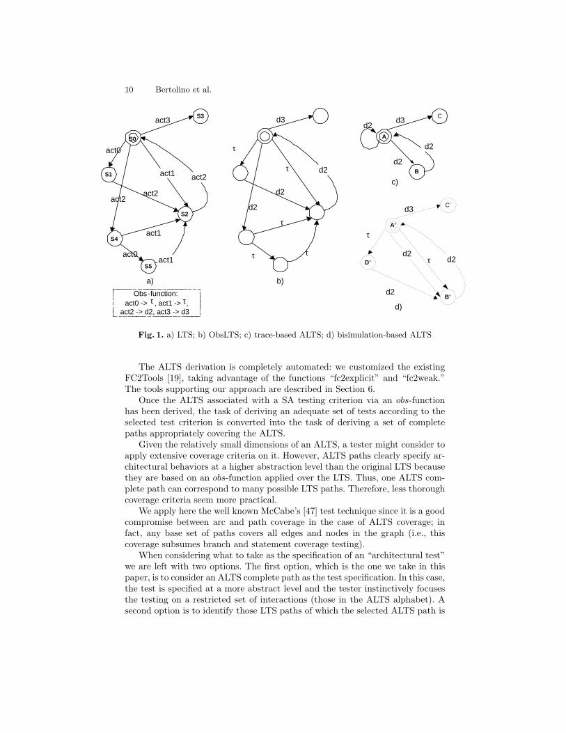
LTS actions L into two groups: relevant interactions R (i.e., those we want toobserve by testing) and non-relevant interactions NR (i.e., those we are not in-terested in at this time), so that L = R ∪ NR and R ∩ NR = ∅. Formally, wedefine an obs-function that maps the relevant LTS labels to a specified interpre-tation domain D, whereas any other (non-relevant) one is mapped to a distinctelement τ . The obs-function may also be considered as a hiding operator thatmakes a set of actions invisible to its environment and may relabel the others inan interpretation domain D. The relabeling may help emphasize the semanticmeaning of observable actions. More precisely:
obs : L −→ L′, so thatobs(r ∈ R) = d ∈ D, obs(n ∈ NR) = τ , and L′ = D ∪ τ .We can also extend the obs-function definition to LTS paths so that if p =
l1.l2. ... .ln, obs(p) = obs(l1.l2. ... .ln) = obs(l1).obs(l2). ... .obs(ln).We then use the obs-function as a means to derive a smaller automaton from
the LTS which still expresses all high-level behaviors we want to test, but hidesaway any other irrelevant behavior. The automaton is called an Abstract LTS(ALTS).
The ALTS is obtained from the LTS via two transformations: i) by relabelingeach transition in LTS according to the obs-function, and ii) by minimizingthe resulting automaton with respect to a selected equivalence relation. Therelabeled automaton is called the ObsLTS, and the minimized one is the ALTS.
For minimization, we analyzed trace- and bisimulation-based equivalences,both familiar from the theory of concurrency [36]. If one wants to reduce as muchas possible the number of τ transitions and corresponding nodes, then a traceequivalence can be considered. In fact, this equivalence abstracts from τ -labeledtransitions and for any computational paths concentrates only on transitionsthat are different from τ . A bisimulation-based equivalence is more suited whenone wants to observe how the system evolves step-by-step, even along τ -moves(preserving the LTS branching structure).
Figure 1 gives an example of the ALTS construction: the original LTS isanalyzed, identifying the observation of interest (Figure 1.a); the abstractionis applied over this LTS with respect to the selected obs-function (Figure 1.b);and finally the trace equivalence minimization function is applied. The resultingALTS is shown in Figure 1.c. Figure 1.d, in contrast, presents a bisimulation-based minimization. It can be seen that the latter gives more information on theoriginal LTS structure.
Taking into consideration that i) the aim of ALTS is to provide a morecompact and analyzable graph, and that ii) the ALTS automaton is built tohighlight only interesting behaviors, the trace equivalence is more suitable forour purposes.
In [39] we prove that the ALTS generation process is correct and complete,that is, each ALTS path comes from a LTS path (ALTS does not introduce newpaths) and each LTS path can be mapped onto an ALTS path (ALTS does notlose information).
10 Bertolino et al.
act2
act1
act1 S1
S5
S2
act0
a) b)
S4
act0
act2
act1
act2
d2
d2 c)
S3 act3 d3
B
A
C d3
d2
d2
d2
S0
Obs -function: act0 -> , act1 -> ,
act2 -> d2, act3 -> d3
d2
d2 D’
B’ d2
C’ d3
d2
d)
A’
τ
τ
τ
τ τ
τ
τ
τ τ
Fig. 1. a) LTS; b) ObsLTS; c) trace-based ALTS; d) bisimulation-based ALTS
The ALTS derivation is completely automated: we customized the existingFC2Tools [19], taking advantage of the functions “fc2explicit” and “fc2weak.”The tools supporting our approach are described in Section 6.
Once the ALTS associated with a SA testing criterion via an obs-functionhas been derived, the task of deriving an adequate set of tests according to theselected test criterion is converted into the task of deriving a set of completepaths appropriately covering the ALTS.
Given the relatively small dimensions of an ALTS, a tester might consider toapply extensive coverage criteria on it. However, ALTS paths clearly specify ar-chitectural behaviors at a higher abstraction level than the original LTS becausethey are based on an obs-function applied over the LTS. Thus, one ALTS com-plete path can correspond to many possible LTS paths. Therefore, less thoroughcoverage criteria seem more practical.
We apply here the well known McCabe’s [47] test technique since it is a goodcompromise between arc and path coverage in the case of ALTS coverage; infact, any base set of paths covers all edges and nodes in the graph (i.e., thiscoverage subsumes branch and statement coverage testing).
When considering what to take as the specification of an “architectural test”we are left with two options. The first option, which is the one we take in thispaper, is to consider an ALTS complete path as the test specification. In this case,the test is specified at a more abstract level and the tester instinctively focusesthe testing on a restricted set of interactions (those in the ALTS alphabet). Asecond option is to identify those LTS paths of which the selected ALTS path is
Lecture Notes in Computer Science 11
an abstraction. Because LTS paths are more detailed than ALTS paths, in thiscase the tester would have more information about how to perform the tests,but also stricter requirements; that is, the tester doesn’t have as much freedomin choosing the code-level tests. In practice, it might actually be more difficultto test the conformance of source code to the test specification.
In either case (ALTS or LTS path), an architectural test is essentially asequence of system actions that are meaningful at the SA level. They can berepresented by UML-like sequence diagrams in which each box represents a SAcomponent, while arrows represent actions performed by the components, i.e.,the (A)LTS labels. The difference in the two options is the level of abstractionat which the sequence is described.
To derive from an ALTS path one or more corresponding LTS paths, we havedeveloped an algorithm, described in [39]. The idea is that after an ALTS-basedset of paths has been chosen, we can find out what the selected observationfunction is hiding; that is, we can identify those LTS paths corresponding to theselected ALTS path. This step could also be automated by adapting the TestGeneration and Verification (TGV) tool [20], inside the Caesar/Aldebaran [13]toolset (see also Section 7.2).
In this process, we may find many LTS paths corresponding to an abstractpath. The strategy we applied for reducing the number of LTS paths is a transi-tion rules coverage criterion: for each ALTS path, we want to derive enough LTSpaths to cover as many transition rules as possible, in a sense trying to considerall possible system behaviors corresponding to an abstract test sequence.
4.2 Test Execution Stage
In this section we will try to understand how a tester can use the architecturalpaths to actually test whether the source code conforms to the architecturaldescription.
Of course, the two problems of traceability and test execution, introduced inSection 2.1, remain. Note that the traceability problem is here even exacerbatedby the distance between the code and the SA-level of abstraction, which is nec-essarily high. Several researchers have recognized the importance and difficultyof this problem [48, 41], but no one has yet found a general solution.
In our analysis, we identify different factors characterizing the mapping be-tween the two levels: the development process, the relationships among archi-tectural components and the source code, and the SA-level of abstraction.
If a well-formalized architecture-based development process is in place, SAspecifications can be used to formally drive the generation of low-level designand code, and thus the correspondence is maintained throughout the process.For instance, some ADLs (such as C2ADL [11] and xADL [16]) provide devel-opment support for implementing software architectures in Java and C++ [12].Explicit mapping rules drive the source-code implementation of architecturalcomponents, connectors, and messages via objects. However, such a process can-not generally be assumed, and would severely restrict the software developer’schoices. Moreover, rigorous formal approaches to relate architectural elements
12 Bertolino et al.
and code are not yet current practice in SA-based processes, as illustrated forinstance in [4, 27].
In our experience, due to real-world constraints, SA specifications and low-level design have been intermixed without any formal mapping. While this iscertainly not an ideal process, it is a realistic and plausible approach. In general,the problem is to provide a way to identify a sequence of low-level operationsimplementing a high-level behavior.
We first analyzed the system implementation to understand how architecturalactions (e.g., high-level functionalities) are implemented in the code by sequencesof partially ordered code level operations.3
Assuming for instance that the SA is implemented in Java, we map actionsinto sequences of method calls. If each action is implemented, at the low level,by a sequence of methods calls, it would be useful to understand how sequencesof these actions (i.e., an architectural test) are implemented by the source code.
Two alternatives may be taken into account: i) each action is implementedby a sequence of operations, and they run sequentially; or ii) the actions canrun concurrently. In the former case, a sequence of architectural actions is im-plemented by the sequential execution of the respective low-level sequence dia-grams. In the latter case, the operations may interleave with each other. Notethat in this context, “acti before actj” (where actk is a generic action) does notmean that all the operations implementing acti must run before all the opera-tions implementing actj . It means that some operations that identify the actiontermination must be executed following a given order, whereas the others maybe run in any order.
We finally run the code and evaluate the execution traces with respect tothe expected ones to analyze the source code conformance with respect to thearchitectural behavior. To execute the desired test sequence, one can use eithera deterministic or a nondeterministic approach (see Section 2.1).
In summary, the approach we devised can be conceptually decomposed intofour substeps:
1. the SA path to be tested is represented as an ordered sequence of events.For instance, UML [45] stereotyped Sequence diagrams [24] can be used torepresent these scenarios, where each box represents an SA component, whilearrows represent actions performed by the components;
2. for each action in the SA path, the tester identifies the code level sequence(again, for instance, specified as UML Sequence Diagrams) implementing itsbehavior. These sequence diagrams represent how one action of the SA pathis implemented in the code;
3. given the SA path to be tested, the tester combines the code level sequencediagrams corresponding to each action. The global sequence diagram so ob-tained represents a source code scenario implementing the SA path. Thetechnical details of this step are discussed in [9];
3 Note that more than one implementation sequence, might correspond to one LTSaction. In such cases, to test the architectural action, all of them should be consid-ered.
Lecture Notes in Computer Science 13
4. the tester runs the code to check whether the sequence diagram generatedin substep 3 is correctly implemented by the system. Since the system runsseveral concurrent processes, in general it is very difficult to trace system be-havior. In fact, multiple executions of a concurrent program with the sameinput may exercise different sequences of interactions and may produce differ-ent results. A pragmatic approach here is to apply nondeterministic testingfor some attempts; if the expected sequence of events is not observed, thena deterministic approach [14] could be applied to force the desired behavior.
Implementing each of the above substeps, in practice, involves several difficultproblems, as we discussed in [9].
5 An application example
Collaborative writing (CW) is one discipline of the multi-disciplinary researcharea known as Computer Supported Cooperative Working (CSCW). Collabora-tive writing is defined in [32] as: “the process in which authors with differentexpertise and responsibilities interact during the invention and revision of acommon document”. A CW system involves two or more people (geographi-cally distributed) working together to produce a common document. CW sys-tems are often categorized according to the time/location matrix in two majorgroups. First, there are systems supporting synchronous editing. This group ofCW system provides changes to the cooperative team partners (i.e. authors andco-authors) in real time. The second group is related to asynchronous writingtools. To better support all the CW stages, in literature have been proposed alsosemi-synchronous CW systems supporting the integration of asynchronous andsynchronous styles of work. Since semi-synchronous CW systems seem to be thebest solution for the complete support of all the activities related to the CW wefocus on such systems.
The actors of a CW system are authors, co-authors and the manager. Themanager divides the work of writing between groups of users (authors and co-authors). She will provide document templates, links and whatever may be ofhelp to the realization of the document. Authors can be required to write aspecific portion of a book/paper. They have to observe the document formatsproposed by the manager and they can delegate one of more co-authors to pro-duce portions of the document. The realization of such a document foresees acertain cooperation, and information exchange, between the manager and au-thors, between the authors and co-authors and among the authors themselves.A list of requirements a CW has to implement is described in [26].
From an architectural viewpoint, a CW system operates in a heterogeneoushardware environment where authors can edit, change and exchange documents,which are stored in a shared database. The CW software architecture we use inthis paper is borrowed from [26]. This CW system is a three-tier applicationcomposed by the following four components:
14 Bertolino et al.
info, fail1
update2, query2
CWE DSS
DBO
IUI k
...
update1, query1
reg, unreg, strEd, grpEd,
lIn, lOut, accEd, accSh,
hist,
open, close, read, write, replicate
res2 res1
fail2, ok, rview,
wview, lcopy,
lwview
Fig. 2. A Software Architecture description of a CW system
– an Integrated User Interface (IUI): it is an integrated environment of toolsfor editing, navigation, display of awareness communication among the groupmembers and import and export of data from external applications;
– a CW Engine (CWE): it provides all services useful to perform a groupactivity in the CW context. It handles a list of CW activities, such as, userregistration and deregistration, user login and logout, users group definitionand editing;
– a Document Storage Service (DSS): it is an abstraction of the physical con-tainer of the shared documents that are logically partitioned according totheir structure. In an asynchronous working mode we use version-controlleddocuments. In a synchronous working mode it is shared among the users andwe have to use pessimistic concurrency control;
– a Database Object (DBO): it stores all group awareness information usefulto support a group activity.
Figure 2 shows the CW SA. It depicts the different components, the architec-ture topology and the list of services each component provides and/or requires.The meaning of each service is explained in [26]. The notation IUIk means thatmany instances of the IUI component can be present at the same time. Thebehavior of each component (in terms of services required and provided) hasbeen specified using the Finite State Process (FSP2) [21] process algebra. Eachcomponent behavior is described by an LTS which is automatically generatedby the Labeled Transition System Analyzer (LTSA) tool [31].
By running the LTSA tool on the CW FSP specification (assuming that twoIUIs are working concurrently), we obtain a (minimized) LTS composed of 47states with 76 transitions (assuming only one IUI is connected). On this we

Lecture Notes in Computer Science 15
apply the method for test selection described in Section 4. A list of interestingobservations we could make on this global LTS includes:
1. Interaction between a subset of the architecture components;2. Scenario-based testing (given a selected interaction scenario, we want to test
a subgraph implementing only such scenario);3. Input/Output for a selected component only.
In the following of this section, we propose samples of the first two observa-tions listed above.
Related to the first observation (interaction between components), we focuson the following testing criterion: “all those behaviors involving the interactionsfrom IUI to CWE”. This criterion needs to be formally expressed by an obs-function. In this case, D will contain all and only the actions (i.e., elementsof the LTS alphabet) that specifically involve the communication among theselected components. Such actions are “reg”, “unreg”, “strEd”, “grpEd”, “lin”,“lout”, “accEd”, “accSh”, and “hist”. Figure 3 shows the obs-function definedfor the given criterion, called IUI-to-CWE obs.
D = {reg, unreg, strEd, grpEd, lin, lout, accEd, accSh, hist}
obs (reg) = Register obs (unreg ) = Unregister obs (strEd) = Structure Editing obs (grpEd) = Group Editing obs (lin) = Login obs (lout) = Logout obs (accEd) = Access to Documents obs (accSh) = Access Information obs (hist) = History For any other T i , obs (T i ) = tau
Fig. 3. Obs-function for the IUI-to-CWE testing criterion
Given the IUI-to-CWE criterion, and by applying reduction and minimiza-tion algorithms, we have derived the ALTS depicted in Figure 4 (label S0 identi-fies the initial state, that in this example also coincides with the only final one).This ALTS represents in a concise, graphical way how the IUI requires servicesto the CWE component.
Following the McCabe’s path coverage criterion [47], we can select NP = m- n + 1 independent paths, where “m” identifies the LTS arcs and “n” the LTSnodes. NP is “precisely the minimum number of paths that can, in (linear) com-bination, generate all possible paths through the module” [47]. Applying thismetric to the IUI-to-CWE, we can get 8 independent paths as listed below:
16 Bertolino et al.
Logout
S0 S1 S2
S3
S4
S5
Structure Editing
Group Editing
Register, Unregister, Access Information, History
Access to Documents
Login
Structure Editing
Login
Logout
Login
Logout Logout
Register, Unregister, Access Information, History
Fig. 4. ALTS for the IUI-to-CWE testing criterion
Path1: S0StructureEditing−→ S1
GroupEditing−→ S4AccesstoDocuments−→ S3
Logout−→ S5Login−→
S0
Path2: S0StructureEditing−→ S1
GroupEditing−→ S4AccesstoDocuments−→ S3
StructureEditing−→S1
GroupEditing−→ S4AccesstoDocuments−→ S3
Logout−→ S5Login−→ S0
Path3: S0StructureEditing−→ S1
GroupEditing−→ S4AccesstoDocuments−→ S3
Logout−→ S2Login−→
S3Logout−→ S5
Login−→ S0
Path4: S0Login−→ S0
Path5: S0Logout−→ S5
Login−→ S0
Path6: S0AccessInformation−→ S3
StructureEditing−→ S1GroupEditing−→ S4
AccesstoDocuments−→S3
Logout−→ S5Login−→ S0
Path7: S0Logout−→ S2
Login−→ S3Logout−→ S5
Login−→ S0
Path8: S0Logout−→ S2
Login−→ S3Unregister−→ S3
StructureEditing−→ S1GroupEditing−→ S4
AccesstoDocuments−→S3
Logout−→ S2Login−→ S3
Logout−→ S5Login−→ S0
Some of these paths are particularly interesting for testing purposes. For ex-ample, paths 1 to 3 show how the IUI component can initially edit the document
Lecture Notes in Computer Science 17
structure, edit information on other authors, access the document, and eventu-ally logout from the system. Path6 considers the case where an author initiallychecks how other authors are modifying the paper, then, starts accessing thepaper and finally logouts.
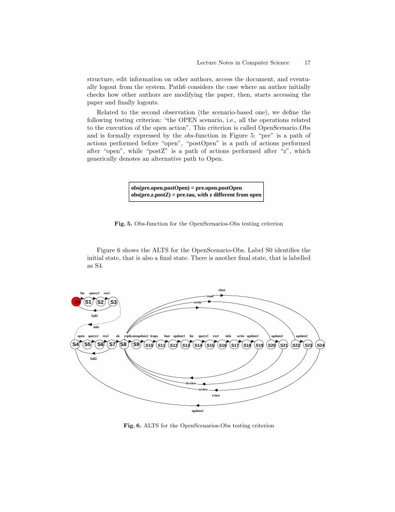
Related to the second observation (the scenario-based one), we define thefollowing testing criterion: “the OPEN scenario, i.e., all the operations relatedto the execution of the open action”. This criterion is called OpenScenario Obsand is formally expressed by the obs-function in Figure 5: “pre” is a path ofactions performed before “open”, “postOpen” is a path of actions performedafter “open”, while “postZ” is a path of actions performed after “z”, whichgenerically denotes an alternative path to Open.
obs( pre. open .postOpen ) = pre . open .postOpen obs(pre. z .postZ ) = pre.tau, with z different from open
Fig. 5. Obs-function for the OpenScenarios-Obs testing criterion
Figure 6 shows the ALTS for the OpenScenario-Obs. Label S0 identifies theinitial state, that is also a final state. There is another final state, that is labelledas S4.
lin query1 res1
info
fail1
open query2 res2
fail2
ok
close
read
write
replicate update2 lcopy lout update1 lin query1 res1 info write update2
lwview
update2
wview
update2
rview
update2
S0 S1 S2 S3
S4 S5 S6 S7 S8 S9 S10 S11 S12 S13 S14 S15 S16 S17 S18 S19 S20 S21 S22 S23 S24
Fig. 6. ALTS for the OpenScenarios-Obs testing criterion
18 Bertolino et al.
A list of ALTS test paths, derived according to McCabe’s technique, is thefollowing:
Path1: S0lin−→ S1
query1−→ S2res1−→ S3
fail1−→ S0
Path2: S0lin−→ S1
query1−→ S2res1−→ S3
info−→ S4open−→ S5
query2−→ S6res2−→ S7
fail2−→ S4
Path3: S0lin−→ S1
query1−→ S2res1−→ S3
info−→ S4open−→ S5
query2−→ S6res2−→ S7
ok−→ S8close−→
S24update2−→ S4
Path4: S0lin−→ S1
query1−→ S2res1−→ S3
info−→ S4open−→ S5
query2−→ S6res2−→ S7
ok−→ S8write−→
S20update2−→ S21
wview−→ S8close−→ S24
update2−→ S4
Path5: S0lin−→ S1
query1−→ S2res1−→ S3
info−→ S4open−→ S5
query2−→ S6res2−→ S7
ok−→ S8read−→
S22update2−→ S23
rview−→ S8close−→ S24
update2−→ S4
Path6: S0lin−→ S1
query1−→ S2res1−→ S3
info−→ S4open−→ S5
query2−→ S6res2−→ S7
ok−→S8
replicate−→ S9update2−→ S10
lcopy−→ S11lout−→ S12
update1−→ S13lin−→ S14
query1−→ S15res1−→
S16info−→ S17
write−→ S18update2−→ S19
lwview−→ S8close−→ S24
update2−→ S4
Path1 shows how the precondition for the execution of the “open” actionmay fail. Path2 shows that the open action may fail. Paths 3 to 6 describe thesequences of actions that may happen when an open is successfully performed.
6 Approach Automation
In our approach, we used several tools to implement the different steps. Initially,an architectural language is used to specify our software architecture. An LTSmodel of the SA dynamics is then automatically generated from this specifica-tion, and abstraction and minimization are applied over the LTS to build anAbstract LTS. Finally, we instrument the source code to analyze the CW behav-ior with respect to the architectural tests. Figure 7 summarizes the frameworkwe use:
LTSA Tool LTS Abstractor
(using FC2Tools)
FSP SA specification
LTS ALTS
Fig. 7. The framework

Lecture Notes in Computer Science 19
1. The Finite State Process (FSP) [21, 34] process algebra is used to specifysoftware component behaviors.
2. The LTSA tool [31] takes an FSP SA specification and gives the corre-sponding LTS as a result.
3. The LTS Abstractor builds abstracted views of the LTS (based on thepreviously discussed theory). It has been implemented by using the existingFC2Tools [19].
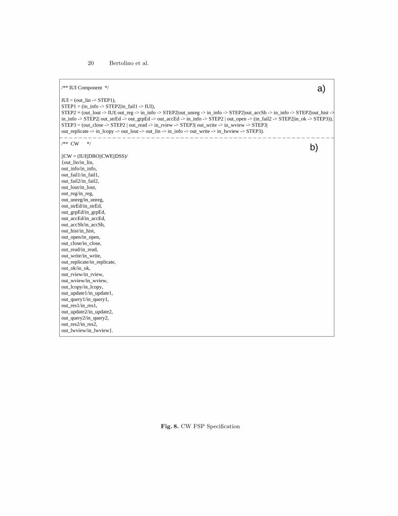
The FSP language provides a concise way of describing LTSs; each FSPexpression can be mapped onto a finite LTS and vice versa. The FSP specificationis based on the definition of processes, whose behavior is modeled by LTSs; eachprocess instance implements an architectural component; several processes canbe combined (with a parallel composition operator) to describe the interactionbetween different processes. An FSP specification comprises a declarative sectiondefining variables and ranges, a section defining the process initial state, and asection describing the other reachable states. Semantically, an FSP process waitsfor an action (e.g., for receiving messages), performs actions (e.g., for sendingmessages) and changes its state. The LTS alphabet is composed of the exchangedmessages.
Figure 8 shows a portion of the FSP specification for the CW system. Forthose not familiar with FSP, Figure 8.a specifies the behavior of the IUI compo-nent. The prefixes “in ” and “out ” identify which are IUI’s inputs and outputs,respectively. Figure 8.b is used to put the various processes in parallel, specify-ing how the LTSs cooperate. This specifies how the CW system behaves, thatis, how the IUI, DBO, CWE, DSS and DBO processes have to be put in parallelto describe the whole system behavior.
Each FSP process can be described by an LTS model that contains all thestates a process may reach and all the transitions it may perform. The LTSAtool supports the FSP language by automatically generating the LTSs of eachFSP process. The tool provides graphical and textual visualization of the result-ing LTSs, allows for evaluating process properties (i.e., safety, deadlock, reach-ability), supports specification animation to facilitate interactive exploration ofsystem behavior and can be used to put different processes in parallel. This lastfeature allows us to obtain a global LTS model of the system.
The observation of the LTS via an abstraction mechanism has been imple-mented by using the FC2Tool. In particular, we took advantage of a functioncalled “fc2explicit” provided by the tool for comparing two “.FC2” graphs. Thefirst graph is the one we want to abstract (the architectural LTS), and the secondone (in the following, Obs-graph) is a graph we generate once the observation isspecified.
By running the “fc2explicit -abstract LTS.fc2 Obsgraph.fc2 > ALTS-nm.fc2”command, we can compare the two graphs and generate a non-minimized ALTS.The “fc2explicit -<opt> ALTS-nm.fc2 > ALTS.fc2” command generates theminimized graph, i.e., the ALTS.
20 Bertolino et al.
a)
b)
/** IUI Component */
IUI = (out_lin -> STEP1), STEP1 = (in_info -> STEP2|in_fail1 -> IUI), STEP2 = (out_lout -> IUI| out_reg -> in_info -> STEP2|out_unreg -> in_info -> STEP2|out_accSh -> in_info -> STEP2|out_hist -> in_info -> STEP2| out_strEd -> out_grpEd -> out_accEd -> in_info -> STEP2 | out_open -> (in_fail2 -> STEP2|in_ok -> STEP3)), STEP3 = (out_close -> STEP2 | out_read -> in_rview -> STEP3| out_write -> in_wview -> STEP3| out_replicate -> in_lcopy -> out_lout -> out_lin -> in_info -> out_write -> in_lwview -> STEP3).
/** CW */
||CW = (IUI||DBO||CWE||DSS)/ {out_lin/in_lin, out_info/in_info, out_fail1/in_fail1, out_fail2/in_fail2, out_lout/in_lout, out_reg/in_reg, out_unreg/in_unreg, out_strEd/in_strEd, out_grpEd/in_grpEd, out_accEd/in_accEd, out_accSh/in_accSh, out_hist/in_hist, out_open/in_open, out_close/in_close, out_read/in_read, out_write/in_write, out_replicate/in_replicate, out_ok/in_ok, out_rview/in_rview, out_wview/in_wview, out_lcopy/in_lcopy, out_update1/in_update1, out_query1/in_query1, out_res1/in_res1, out_update2/in_update2, out_query2/in_query2, out_res2/in_res2, out_lwview/in_lwview}.
Fig. 8. CW FSP Specification
Lecture Notes in Computer Science 21
7 Putting the Approach in the Global Picture
We have described so far an original approach for the derivation of SA-based con-formance test cases. Our aim is to integrate this approach in industrial practice.This requires that the approach is enhanced in two dimensions: standardizingthe input modelling notation, i.e., the SA description; and, increasing the degreeof automation, that can be done efficiently by exploiting existing tools.
7.1 Standardizing SA Description
SA stakeholders in academia and in industry understand SAs in different ways,use them with different goals and unfortunately, specify them with differentformalisms. Researchers have proposed formal ADLs in order to make auto-matic analysis and validation possible. Practitioners use more informal notations,sometimes, just simple box-and-line notations.
As a way to provide a standard notation to describe SAs, the Unified Mod-eling Language (UML) [45] is more and more used. UML has now gained a wideacceptance as the de-facto standard for object oriented modeling. Although itsoriginal purpose was for detailed design, its extension mechanisms (i.e., the pos-sibility to extend the UML semantics associated to modeling elements) makeit potentially applicable in contexts outside the object-oriented world (e.g., [15,29]). Moreover, its multi-view modeling approach [30] allows to use differentdiagrams to describe different system perspectives.
In the last few years, various approaches to incorporate architectural descrip-tions in the UML framework have been proposed. In [35], the authors discusstwo different approaches, adhering to the requirement that the resulting notationstill complies to standard UML.
In the first approach, UML is used “as is”, i.e., the existing UML notation isused to represent SAs. One relevant drawback of this approach is that specific SAconcepts (for example, connectors and rules) do not have direct counterparts inUML. Moreover, UML imposes structural and compositional constraints whichdo not apply to SA descriptions and viceversa.
The second approach, instead, constrains the UML meta model using UMLbuilt-in mechanisms. It has been used to formalize architectures in C2, Rapideand Wright [11, 33, 2]. However, application of this approach showed that the useof the formal Object Constraint Language (OCL), in order to extend the UMLstandard notation, strongly limits the use of UML tools to support architecturalmodels. Moreover, the ambiguity still existing in the UML semantics, makes itdifficult to model some architectural concepts.
This research direction can also be relevant for testing purposes, becauseUML-based testing is a very active research area (e.g., [3, 1, 10]). For testing, weneed to express besides the structure also the behavior of the architecture underanalysis. As already said, behavioral modelling is in fact the key instrument inSA conformance testing. For instance in [35], state diagrams have been used tospecify behavioral information.

22 Bertolino et al.
Indeed, the use of a UML compliant model for SAs would allow us to exportresults from the UML-based testing area to the SA domain.
Several methods and tools for UML-based testing have been proposed. Noneof these however focuses explicitly on testing of the SA. An ongoing Europeanproject for automated generation of test cases from a UML model 4 is AGEDIS[1]. Interestingly, the system model it takes in input is essentially composedof class diagrams, for describing the system components, and state diagrams,for describing the behavior of components, plus stereotypes and tagged values.This coincides exactly with the basic set of diagrams identified in the secondapproach of [35]. Therefore, it is possible that a tool such as AGEDIS could beadapted to SA-based testing. However, even though the notation and underlyingtechniques are the same, conceptual differences exist and should be investigatedby experimentation.
7.2 Importing Automation from Existing Tools
If we rethink our approach in terms of the existing and now well-settled theory ofconformance testing from formal specifications (as summarized in Section 2.2),it is evident that from a technical point-of-view several commonalities exist.
Indeed, the methodology and tools used are basically the same. The behav-ior semantics of the system is expressed in both cases by LTSs, possibly withsome extensions (in Tretmans’ testing theory IOTSs, including input and out-put labelling of events). On the LTS model, formal methods need to be appliedfor restricting the analysis to relevant classes of behavior, because an exhaus-tive coverage of the LTS is not feasible. More precisely, we need a techniquefor reducing the possible sequences of transitions to a limited number of testsequences. In our approach we have used an observation function on the LTSwhich finally (after renaming and reductions) gives back an ALTS. On the ALTSwe can then more easily identify a set of test sequences, but as we have shownthese are very abstract and far from the concrete level at which these tests haveto be eventually executed. In contrast, in TGV, the identification of relevant testsequences is made by specifying a test purpose. Given a test purpose, a set ofpaths on the LTS is derived which satisfies the test purpose and corresponds toa set of test sequences, defined over the LTS.
Roughly, a test purpose would correspond in our approach to a path on theALTS. Intuitively, then, we could in principle reformulate our approach withinthe context of TGV (by translating the obs-function in terms of guidelines forderiving a test purpose), with the advantage of being able to use a well devel-oped and mature set of tools [13]. Actually, the above cited AGEDIS project [1]incorporates the TGV algorithms.
However, the intermediate step of the ALTS is not explicitly supported inTGV, and we believe that it introduces a useful and intuitive means for reasoningat the complex architectural level by separately considering differing classes of
4 More precisely, a subset of UML, called the AML, for Agedis Modelling Language,has been formally defined.
Lecture Notes in Computer Science 23
behavior. ALTSs offer specific views of the SA dynamics by concentrating onrelevant features and abstracting away from less interesting features. ALTS isa graphical tool we provide that allows the software architect to more easilyidentify those behavioral patterns that are meaningful for validation purposes.
Conceptually, there are significant differences between our approach and ex-isting ones:
i) The SA description tries to capture SA-relevant behaviors alone, whileabstracting away other system functions. Thus, our tests specifically belong tothe integration testing stages and certainly do not aim to test the system ascompletely as possible, as in traditional specification-based test approaches.
ii) The abstraction level of the reference model and its relative “distance”from the implementation under test varies much in the two contexts. In SA-basedtesting, this distance is purposely very high, whereas in existing approaches tospecification-based testing, this is often thought as being low. In other words,a high abstraction level is a basic assumption of our approach, whereas tradi-tional approaches require a close distance between the reference model and theimplementation.
8 Conclusions and Future Perspectives
As testified by the collection of papers in this book, SA can play an importantrole throughout the software life cycle. However, while the literature is richin approaches for design and analysis based on SA, relatively little has beenproposed so far for SA-based testing. Our research investigates how the SAconcepts, methods, and tools can be usefully exploited in the conformance testingof a large distributed system against its high-level specifications.
Our approach to SA-based testing essentially consists of deriving a set ofarchitectural test sequences by covering abstracted views of the LTS descriptionof the SA behavior. We have here illustrated it on the CW case study.
Our experience in using the approach on some real-world case studies re-vealed that practical difficulties can hinder its direct application in industry.Deriving suites of architectural test cases according to some notion of coveragemay be relatively easy, with the support of adequate tools. What can be morecomplicated is to subsequently establish a relationship that maps these high-leveltest sequences on concrete, executable test cases. The problem arises especiallyin absence of a rigorous, formalized refinement process from the SA specifica-tion down to the source-code, as it is still common industrial practice. In ourview, the only means to investigate such a tough problem is through empirical,hands-on investigation.
On the other hand, we might not even have a global architectural model atour disposal. This can happen for several reasons: i) architectural componentsmay be described through complex models, in terms of states and transitionsand putting these models together may give rise to a state explosion problem. ii)The architectural models may be incomplete, which means that some componentbehaviors are unknown or components are not completely specified. These may
24 Bertolino et al.
be very common situations in industrial contexts. We thus are investigating thepossibility of generating abstract observations and test sequences directly frompartial architectural models.
As discussed in the paper, future developments of the approach will encom-pass on one side the possibility of using the standard UML notation for modellingthe SA behavior. This can be useful in two respects: for pushing the industrialusage of rigorous SA-based testing methods, and for exploiting the rich reposi-tory of UML-based test techniques. On the other side, we are also investigatingthe relation between our approach and the framework of conformance testing ofdistributed reactive systems, already implemented in the TorX and TGV tools,and under development in the AGEDIS tool.
Finally, empirical investigations on more case studies, possibly developed byusing different development processes and programming paradigms, are neces-sary to further generalize and refine the approach.
Acknowledgments
We would like to acknowledge the Italian MURST/MIUR national projects SAL-ADIN and SAHARA, which partially supported this work. We are indebted toAntonio Bucchiarone, who provided the CW case study, and to Thierry Jeronfor his constructive help in applying the TGV tool on the CW.
References
1. The AGEDIS Project: Automated Generation and Execution of Test Suites forDistributed Component-based Software. On-line at http://www.agedis.de
2. Allen, R., Garlan, D.: A Formal Basis for Architectural Connection. ACM Trans.on Software Engineering and Methodology, Vol. 6, N. 3, pp. 213-249, July 1997.
3. Basanieri, F., Bertolino, A., Marchetti, E.: The Cow Suite Approach to Planningand Deriving Test Suites in UML Projects. In Proc. 5th Int. Conf. UML 2002,Dresden, Germany. LNCS 2460 (2002), pp. 383-397.
4. Bass, L., Clements, P., Kazman, R.: Software Architecture in Practice. SEI Seriesin Software Engineering, Addison-Wesley, 1998.
5. Bertolino, A.: Knowledge Area Description of Software Testing. In SWEBOK,Joint IEEE-ACM Software Engineering Coordinating Committee. On-line at:<http://www.swebok.org>.
6. Bertolino, A.: Software Testing Research and Practice. Invited presentation at ASM2003, Taormina, Italy. LNCS 2589 (2003), pp. 1-21.
7. Bertolino, A., Inverardi, P.: Architecture-based software testing. In Proc. ISAW96,October 1996.
8. Bertolino, A., Corradini, F., Inverardi, P., Muccini, H.: Deriving Test Plans fromArchitectural Descriptions. In ACM Proc. Int. Conf. on Software Engineering(ICSE2000), pp. 220-229, June 2000.
9. Bertolino, A., Inverardi, P., Muccini, H.: An Explorative Journey from ArchitecturalTests Definition downto Code Tets Execution. In IEEE Proc. Int. Conf. on SoftwareEngineering (ICSE2001), pp. 211-220, May 2001.
Lecture Notes in Computer Science 25
10. Briand, L., Labiche, Y.: A UML-Based Approach to System Testing. Software andSystem Modeling 1(1), 2002, pp. 10-42.
11. The C2 style and ADL. Project web page on-line at:<http://www.isr.uci.edu/architecture/c2.html>.
12. The C2 Framework. On-line at: <http://www.isr.uci.edu/architecture/software.html>.13. Caesar/Aldebaran Tool (CADP). On-line at: <http://inrialpes.fr/vasy/cadp>.14. Carver, R. H., Tai, K.-C.: Use of Sequencing Constraints for Specification-Based
Testing of Concurrent Programs. IEEE Trans. on Software Engineering, Vol. 24,N. 6, pp. 471-490, June 1998.
15. Conallen, J.: Building Web Applications with UML. The Addison-Wesley ObjectTechnology Series.
16. Dashofy, E. M., van der Hoek, A., Taylor, R. N.: An Infrastructure for the RapidDevelopment of XML-Based Architecture Description Languages. In Proc. of the24th Int. Conf. on Software Engineering, 2002.
17. De Nicola, R., Hennessy, M.: Testing Equivalences for Processes. TheoreticalComputer Science, 34: 83-133, (1984).
18. Dick, J., Faivre, A.: Automating the Generation and Sequencing of Test Cases fromModel-Based Specifications. In J.C.P. Woodcock and P.G. Larsen (Eds.), FME’93:Industrial-Strenght Formal Methods, pp. 268-284. LNCS 670, Springer Verlag, 1993.
19. FC2Tools. On-line at: <http://www-sop.inria.fr/meije/verification/quick-guide.html>.
20. Fernandez, J.-C., Jard, C., Jeron, T., Nedelka, L., Viho, C.: An Experiment inAutomatic Generation of Test Suites for Protocols with Verification Technology.Special Issue of Science of Computer Programming, Vol. 29, pp. 123-146, 1997.
21. Finite State Process (FSP). On-line at: <http://www.dse.doc/ic.ac.uk/∼jnm/book/ltsa/Appendix-A.html>.
22. Harrold, M. J.: Architecture-Based Regression Testing of Evolving Systems. InProc. Int. Workshop on the ROle of Software Architecture in TEsting and Analysis(ROSATEA), CNR-NSF, pp. 73-77, July 1998.
23. Harrold, M. J.: Testing: A Roadmap. In A. Finkelstein (Ed.), ACM ICSE 2000,The Future of Software Engineering, pp. 61-72, 2000.
24. Hofmeister, C., Nord, R. L., Soni, D.: Applied Software Architecture. AddisonWesley, 1999.
25. Inverardi, P., Wolf, A. L.: Formal Specifications and Analysis of Software Archi-tectures Using the Chemical Abstract Machine Model. IEEE Trans. on SoftwareEngineering, Vol. 21, N. 4, pp. 100-114, April 1995.
26. Inverardi, P., Tivoli, M., Bucchiarone, A.: Coordinators synthesis forCOTS group-ware systems: an example. In Proc. Int. Workshop on Dis-tributed and Mobile Collaboration, 2003 (DMC 2003). Extended version astechnical Report, University of LAquila, Department of Computer Science,http://www.di.univaq.it/tivoli/cscw techrep.pdf, March 2003.
27. Jacobson, I., Booch, G., Rumbaugh, J.: The Unified Software Development Process.Addison Wesley, Object Technology Series, 1999.
28. Jard, C., Jeron, T.: TGV: Theory, Principles and Algorithms. Proc. Conf. IDPT2002. Pasadena (USA), (2002).
29. Jrjens, J.: UMLsec: Extending UML for Secure Systems Development. Proc. UML2002, Dresden, Sept. 30 - Oct. 4, 2002, LNCS.
30. Kruchten, P.: Architectural Blueprints - The “4+1” View Model of Software Ar-chitecture. IEEE Software, 12(6) November 1995, pp. 42-50.
31. Labelled Transition System Analyzer (LTSA). On-line at: <http://www-dse.doc.ic.ac.uk/∼jnm/book/>.
26 Bertolino et al.
32. Lay, M., Karis, M.: Collaborative writing in industry: Investigations in theory andpractice. Baywood Publishing Company, Amityville, 1991.
33. Luckham, D. C., Kenney, J. J., Augustin, L. M., Vera, J., Bryan, D., Mann, W.:Specification and Analysis of System Architecture Using Rapide. IEEE Trans. onSoftware Engineering, Special Issue on Software Architecture, Vol. 21, N. 4, pp.336-355, April 1995.
34. Magee, J., Kramer, J.: Concurrency: State Models & Java Programs. Wiley, April1999.
35. Medvidovic, N., Rosenblum, D. S., Redmiles, D. F., Robbins, J. E.: Modelingsoftware architectures in the Unified Modeling Language. ACM Transactions onSoftware Engineering and Methodology (TOSEM), Vol. 11 , Issue 1, Jan. 2002.
36. Milner, R.: Communication on Concurrences. International Series on ComputerScience. Prentice Hall International, 1989.
37. Muccini, H.: Software Architecture for Testing, Coordination Models and ViewsModel Checking. PhD thesis, University of L’Aquila, year 2002. On-line at:<http://www.HenryMuccini.com/publications.htm>.
38. Muccini, H., Bertolino, A., Inverardi, P.: Using Software Architecture for CodeTesting Submitted for publication.
39. Muccini, H., Bertolino, A., Inverardi, P.: Using Software Ar-chitecture for Code Testing. Long version of [38]. On-line athttp://www.HenryMuccini.com/publications.htm
40. Richardson, D. J., Wolf, A. L.: Software testing at the architectural level. ISAW-2in Joint Proc. of the ACM SIGSOFT ’96 Workshops, pp. 68-71, 1996.
41. Richardson, D. J., Stafford, J., Wolf, A. L.: A Formal Approach to Architecture-based Software Testing. Technical Report, University of California, Irvine, 1998.
42. TorX Test Tool Information. http://fmt.cs.utwente.nl/tools/torx/introduction.html43. Tretmans, J.: Test Generation with Inputs, Outputs and Repetitive Quiescence.
Software–Concepts and Tools, 17(3):103-120, 1996.44. Tretmans, J.: Testing Concurrent Systems: A Formal Approach. Proc. of CON-
CUR’99, LNCS 1664 (1999), pp. 46–65.45. UML. Object Management Group: OMG Unified Modeling Language (UML),
V1.4, 2001. http://www.omg.org46. de Vries, R. G., Tretmans, J.: Towards Formal Test Purposes. Proc. FATES’01,
Aalborg, Denmark (2001).47. Watson, A. H., McCabe, T. J.: Structured Testing: A Testing Methodology Using
the Cyclomatic Complexity Metric. NIST Special Publication 500-235, August 1996.48. Young, M.: Testing Complex Architectural Conformance Relations. In Proc.
Int. Workshop on the ROle of Software Architecture in TEsting and Analysis(ROSATEA), CNR-NSF, pp. 42-45, July 1998.