Forma Line BIKE FORMA (DDC5): Technical …DDC5)_Ver… · 3.4 3.4.1. Brake Board Models ......
122
F F O O R R M M A A L L I I N N E E BIKE FORMA (DDC5xxx…) Technical Assistance manual REV. 1.1
Transcript of Forma Line BIKE FORMA (DDC5): Technical …DDC5)_Ver… · 3.4 3.4.1. Brake Board Models ......

FFOORRMMAA LLIINNEE BIKE FORMA
(DDC5xxx…) Technical Assistance manual
REV. 1.1


The information in this manual is aimed at QUALIFIED TECHNICAL PERSONNEL, who have been specifically trained by TECHNOGYM and been qualified to carry out fine adjustments and start-ups, as well as major maintenance work and repairs, requiring in-depth understanding of the
equipment, how it works, its safety devices and maintenance procedures.
READ ALL THE INFORMATION IN THIS DOCUMENT VERY CAREFULLY BEFORE CARRYING OUT ANY WORK AT ALL ON THE EQUIPMENT
THERE ARE DANGEROUS VOLTAGE LEVELS EVEN WHEN THE EQUIPMENT IS SWITCHED
OFF
WARNING: The information contained in this document may be changed without prior notification. Technogym does not issue guarantees of any kind regarding this material. Technogym will not be held responsible for any errors contained herein or for any accidental damage or damage consequent to the supply, services or use of this material. This document contains proprietary information that is covered by copyright. All rights are reserved. No part of this document may be photocopied, reproduced or translated into another language without the prior written consent of Technogym. Technogym™ is a trademark owned by Technogym S.p.A. Forma Line – BIKE Forma ™ is a trademark owned by Technogym S.p.A.


Forma Line BIKE FORMA (DDC5): Technical Assistance manual - rev. 1.1
Page i
Contents 1. GENERAL WARNINGS ......................................................................................................................................... 1.1
1.1. INTRODUCTION ................................................................................................................................................... 1.1 1.2. USEFUL ADVICE .................................................................................................................................................. 1.1 1.3. GENERAL REGULATIONS REGARDING SERVICE WORK ......................................................................................... 1.2
2. TECHNICAL SPECIFICATIONS ......................................................................................................................... 2.1
2.1. PRODUCT CODE NUMBERS .................................................................................................................................. 2.1 2.2. SERIAL NUMBER STRUCTURE ............................................................................................................................. 2.2 2.3. PRODUCT CHARACTERISTICS .............................................................................................................................. 2.3 2.4. ENVIRONMENTAL CHARACTERISTICS .................................................................................................................. 2.3 2.5. COMPLIANCE WITH REGULATIONS ...................................................................................................................... 2.3 2.6. MECHANICAL CHARACTERISTICS ........................................................................................................................ 2.4
2.6.1. Bulk dimensions ................................................................................................................................ 2.4 2.6.2. Packing dimensions Europe and Overseas ....................................................................................... 2.5
2.7. WIRING DIAGRAM ............................................................................................................................................... 2.6 2.7.1. Powered Model (ARM Board) .......................................................................................................... 2.6
2.8. CABLES 2.7 2.8.1. CBQ Cables ...................................................................................................................................... 2.7 2.8.2. CU Cables ......................................................................................................................................... 2.7
3. OPERATING PRINCIPLE ..................................................................................................................................... 3.1
3.1. BLOCK DIAGRAM ................................................................................................................................................ 3.1 3.2. LED DISPLAY BOARDS ........................................................................................................................................ 3.2
3.2.1. ARM Board ....................................................................................................................................... 3.2 3.2.2. C-Safe Board .................................................................................................................................... 3.2
3.3. CARDIO RECEIVER BOARD ................................................................................................................................. 3.3 3.3.1. HR (Band) ......................................................................................................................................... 3.3
3.4. BRAKE BOARD ................................................................................................................................................... 3.4 3.4.1. Brake Board Models ......................................................................................................................... 3.5
3.5. ELECTROMAGNETIC BRAKE ................................................................................................................................ 3.6 3.6. SPEED SENSOR ................................................................................................................................................... 3.6 3.7. INPUT MODULE .................................................................................................................................................. 3.6 3.8. BRAKE COMMAND .............................................................................................................................................. 3.7
3.8.1. The Mechanics .................................................................................................................................. 3.7 3.8.2. Control .............................................................................................................................................. 3.7 3.8.3. The signals involved ......................................................................................................................... 3.9
4. ACCESSORIES........................................................................................................................................................ 4.1
4.1. CONNECTION TO THE PC FOR PROGRAMMING ..................................................................................................... 4.1 4.2. MONITOR PLUG FOR C-SAFE PORT ...................................................................................................................... 4.2
5. INSTALLATION INSTRUCTIONS ...................................................................................................................... 5.1
5.1. INSTALLATION .................................................................................................................................................... 5.1 5.2. HANDLING THE EQUIPMENT ................................................................................................................................ 5.2 5.3. FIRST START-UP .................................................................................................................................................. 5.3
6. TROUBLESHOOTING........................................................................................................................................... 6.1
6.1. TROUBLESHOOTING MENU .................................................................................................................................. 6.2 6.1.1. Automatic Tests ................................................................................................................................. 6.3
6.1.1.1. I2C Devices Test .......................................................................................................................................................... 6.3 6.1.1.2. LED Test ...................................................................................................................................................................... 6.4 6.1.1.3. Serial Ports Test ........................................................................................................................................................... 6.4
6.1.2. Manual Test ...................................................................................................................................... 6.4

Forma Line BIKE FORMA (DDC5): Technical Assistance manual - rev. 1.1
Page ii
6.1.2.1. Man. Keyboard Test ..................................................................................................................................................... 6.4 6.2. THE DISPLAY REMAINS OFF ................................................................................................................................. 6.5 6.3. THE DISPLAY SHOWS THE MESSAGE “THE EQUIPMENT IS BLOCKED (COM)” ............................................ 6.7 6.4. THE BRAKE BOARD HAS DETECTED AN ERROR ................................................................................................... 6.8 6.5. THERE IS NO RESISTANCE ................................................................................................................................. 6.11 6.6. THE RESISTANCE IS NOT CORRECT .................................................................................................................... 6.14 6.7. THE SPEED SIGNAL IS NOT CORRECT ................................................................................................................. 6.16 6.8. THERE IS NO HEART FREQUENCY SIGNAL .......................................................................................................... 6.18
6.8.1. HR Receiver (Heart Rate Band) ..................................................................................................... 6.18 6.9. TELEMETRIC SIGNAL OF HEART RATE IS NOT CORRECT ..................................................................................... 6.20
6.9.1. Heart Rate Band ............................................................................................................................. 6.20
7. DISMANTLING THE PARTS ............................................................................................................................... 7.1
7.1. IMPORTANT NOTE ON DISMANTLING...................................................................................................... 7.1 7.2. DISMANTLING THE CONTROL PANEL ................................................................................................................... 7.2 7.3. DISMANTLING THE ARM AND C-SAFE BOARD ..................................................................................................... 7.4 7.4. DISMANTLING THE CARDIO RECEIVER ................................................................................................................ 7.6
7.4.1. HR Receiver (Band) .......................................................................................................................... 7.6 7.5. DISMANTLING THE HANDLEBARS ........................................................................................................................ 7.8 7.6. DISASSEMBLING THE PEDAL AND THE PEDAL LEVER WITH GUARD ...................................................................... 7.9 7.7. DISMANTLING THE GUARD ................................................................................................................................ 7.10 7.8. DISMANTLING THE PULLEY UNIT WITH PEDAL CRANK ....................................................................................... 7.13 7.9. DISMANTLING THE SEAT ................................................................................................................................... 7.15
7.9.1. Dismantling the seat support .......................................................................................................... 7.15 7.9.2. Dismantling the internal bushing .................................................................................................. 7.16 7.9.3. Dismantling the seat group ............................................................................................................. 7.17
7.9.3.1. Dismantling the seat upholstery ................................................................................................................................. 7.17 7.9.3.2. Dismantling the handle pin ........................................................................................................................................ 7.18 7.9.3.3. Dismantling the spring and the handle ....................................................................................................................... 7.19 7.9.3.4. Dismantling the handle support plate ......................................................................................................................... 7.23 7.9.3.5. Dismantling the handle pin ........................................................................................................................................ 7.24
7.10. DISMANTLING THE BELT AND BELT-TENSIONER ............................................................................................... 7.26 7.11. DISMANTLING THE BRAKE AND THE FLYWHEEL UNIT ....................................................................................... 7.28 7.12. DISMANTLING THE SPEED SENSOR .................................................................................................................... 7.30 7.13. DISMANTLING THE BRAKE BOARD ................................................................................................................... 7.31 7.14. DISMANTLING THE PLATFORMS ........................................................................................................................ 7.32 7.15. DISMANTLING THE INPUT MODULE .................................................................................................................. 7.33
8. ADJUSTMENTS ...................................................................................................................................................... 8.1
8.1. BELT TENSION .................................................................................................................................................... 8.1 8.2. ALIGNING THE BELT ............................................................................................................................................ 8.2 8.3. ADJUSTMENT OF THE PLAY ON THE SEAT COLUMN ............................................................................................. 8.3 8.4. ADJUSTING THE POSITION OF THE SPEED SENSOR ................................................................................................ 8.4 8.5. ADJUSTING THE POSITION OF THE BRAKE UNIT .................................................................................................... 8.5 8.6. THE EQUIPMENT IS NOT LEVEL ............................................................................................................................ 8.6
9. EQUIPMENT CONFIGURATION........................................................................................................................ 9.1
9.1. CONFIGURATION OF THE USER MENU .................................................................................................................. 9.1 9.1.1. Language .......................................................................................................................................... 9.3 9.1.2. Units of measurement ....................................................................................................................... 9.3 9.1.3. Maximum exercise time .................................................................................................................... 9.3 9.1.4. Pause time......................................................................................................................................... 9.3 9.1.5. Cooldown time .................................................................................................................................. 9.4 9.1.6. Enabling the TGS.............................................................................................................................. 9.4 9.1.7. Activating the Keyboard ................................................................................................................... 9.5 9.1.8. Modifiability of target heart rate ...................................................................................................... 9.5 9.1.9. Enabling custom messages ............................................................................................................... 9.5 9.1.10. Setting the parameters to default values ........................................................................................... 9.6 9.1.11. Formatting the P&P key ................................................................................................................... 9.6 9.1.12. SN ..................................................................................................................................................... 9.6

Forma Line BIKE FORMA (DDC5): Technical Assistance manual - rev. 1.1
Page iii
9.2. CONFIGURATION OF THE TECHNICAL ASSISTANCE MENU .................................................................................... 9.7 9.2.1. Low kit parameter ............................................................................................................................. 9.9
9.2.1.1. Read from low kit ........................................................................................................................................................ 9.9 9.2.1.2. Write to low kit ............................................................................................................................................................ 9.9 9.2.1.3. Default Setting ........................................................................................................................................................... 9.10 9.2.1.4. Table of Configuration parameters: ........................................................................................................................... 9.10
9.2.2. Operating data ................................................................................................................................ 9.11 9.2.2.1. Read from low kit ...................................................................................................................................................... 9.11 9.2.2.2. Write to low kit .......................................................................................................................................................... 9.12 9.2.2.3. Operating data ............................................................................................................................................................ 9.12
9.2.3. Errors Log ...................................................................................................................................... 9.13 9.2.3.1. Read from low kit ...................................................................................................................................................... 9.13 9.2.3.2. Reset errors ................................................................................................................................................................ 9.13 9.2.3.3. COM.Fault ................................................................................................................................................................. 9.14 9.2.3.4. Display errors ............................................................................................................................................................. 9.14
9.2.4. Standard settings ............................................................................................................................ 9.15 9.2.5. Low kit menu ................................................................................................................................... 9.15
9.2.5.1. Low kit version .......................................................................................................................................................... 9.16 9.2.5.2. Config. registers ......................................................................................................................................................... 9.16 9.2.5.3. Low Kit fault code ..................................................................................................................................................... 9.16
9.2.6. High kit version .............................................................................................................................. 9.16 9.2.7. BOOT version ................................................................................................................................. 9.17 9.2.8. Key Reader Version ........................................................................................................................ 9.17
10. SCHEDULED MAINTENANCE ......................................................................................................................... 10.1
10.1. ROUTINE MAINTENANCE .......................................................................................................................... 10.1 10.2. SPECIAL MAINTENANCE ........................................................................................................................... 10.1
11. APPENDIX ............................................................................................................................................................. 11.1
11.1. TOOLS TO BE USED ........................................................................................................................................... 11.1

Forma Line BIKE FORMA (DDC5): Technical Assistance manual - rev. 1.1
Page iv
Page blank.

Forma Line BIKE FORMA (DDC5): Technical Assistance manual - rev. 1.1
Page 1.1
1. GENERAL WARNINGS
1.1. INTRODUCTION
This document has been prepared specifically for Technogym After Sales Service with the aim of providing authorised personnel with the information for carrying out maintenance and repair operations in the correct manner. A thorough understanding of the technical data contained herein is absolutely fundamental for the operator to achieve the highest level in professional training. In order to make the reading more readily understandable, the paragraphs have illustrations and diagrams which highlight the specific subject matter. This manual includes informative notes with specific meanings:
DANGER: non observance may result in accident or injury.
WARNING: non observance may cause damage to the machine.
CAREFUL: Information about the operation in progress.
Observation about the operation in progress.
1.2. USEFUL ADVICE
Technogym advises you to program your technical assistance task in the following way: • Make a careful assessment of the impressions given by the Customer regarding the equipment's operating
faults and formulate some appropriate questions to clarify the symptoms relating to the defect. • Be clear in your diagnosis of the reasons for the fault. You can pick up the basic theoretical
information from this manual, but this needs to be bolstered by your own personal experience and by taking part in the training courses organised periodically by Technogym.
• Plan the repair work in a rational manner so as to avoid wasting any time, e.g. collecting spare parts, preparing tools and equipment etc.
• Gain access to the part that needs to be repaired and limit yourself to the essential operations. On this point, it will be extremely helpful if you consult the dismantling sequences shown in this manual.

Forma Line BIKE FORMA (DDC5): Technical Assistance manual - rev. 1.1
Page 1.2
1.3. GENERAL REGULATIONS REGARDING SERVICE WORK
1. Always mark components or positions which might easily be confused with each other during re-assembly.
2. Use original Technogym spare parts and recommended brand lubricants. 3. Use special tools when specified to do so. 4. Consult the Technical Newsletters as they might contain more up-to-date details on regulation
and servicing procedures compared to those in this manual. 5. Before undertaking any work, check that the recommended tools are available and that they are
in good condition. 6. With regard to the procedures given in this manual, only use the tools that have been indicated.
Tool measurements in this manual are expressed in mm.

Forma Line BIKE FORMA (DDC5): Technical Assistance manual - rev. 1.1
Page 2.1
2. TECHNICAL SPECIFICATIONS
2.1. PRODUCT CODE NUMBERS
The equipment code numbering takes into account all the possible variants and available options for the products. The equipment code number, which does not contain the Serial Number, is made up of 16 alphanumeric characters as follows: Characters Description Values and meaning
1,2, Type of Line DD = FORMA LINE 3, Type of equipment C = Bike Forma 4, Model 5 = 500 5, Type of energy supply used 3 = Powered 6, Type of Display L = LED 7, Built-in devices N = None
8, 9, Frame Colour, AN = Anthracite
10, 11, Upholstery Colour, 00 = none NA = Nero
12, Guard Colour, R = Renault Grey 13, Type of standard TV, 0 = none
14,15, Language,
BR = Portuguese DA = Danish DE = German ES = Spanish FR = French IT = Italian JP = Japanese NL = Dutch RU = Russian TR = Turkish UK = British English US = American English ZH = Chinese
16. Type of packing. S = Overseas For example, a possible code number could be the following:
DD C 5 3 L N AN NA R 0 UK S

Forma Line BIKE FORMA (DDC5): Technical Assistance manual - rev. 1.1
Page 2.2
2.2. SERIAL NUMBER STRUCTURE
The Serial Number is made up of 14 alphanumeric characters as follows:
Characters Description Values and meaning
1,2,3,4,5,6, Type of product,
DD = FORMA LINE C = Bike Forma 5 = 500 3 = Powered
7,8, Year of production, L = LED 9,10,11,12,13,14. Progressive. 11 = 2011 For example, a possible code number could be the following:
DD C 5 3 L 11 000001
Forma Line BIKE FORMA (DDC5): Technical Assistance manual - rev. 1.1
Page 2.3
2.3. PRODUCT CHARACTERISTICS
Bike Forma Power supply: 100-240Vac
50-60Hz Energy consumption: Max 35W (50VA) Consumption in Stand-by: 9W
Resistance: 30-500Watt (a 70 rpm) Difficulty Levels: 1 - 25 Max. user weight: 180Kg – 397lb Seat height adjustment: SI Steps of seat height adjustment: 12,5mm HR Monitoring: Telemetry Plug & Play System: SI
Total number of programs:
3: Quick start
Goal CPR
Languages available: 13: UK English, US English, Italian, German,
Spanish, French, Dutch, Portuguese, Japanese, Chinese, Russian, Turkish, Danish
2.4. ENVIRONMENTAL CHARACTERISTICS
Temperature In operation from 5° to 35° C In storage from -10° to 70° C
Dampness In operation from 30% to 80% without condensation In storage from 5% to 85% without condensation
2.5. COMPLIANCE WITH REGULATIONS
Directives EUROPE
EMC EN55014-1 EN55014-2
ELECTRICAL safety EN60335-1
MECHANICAL safety EN957-1 EN957-2
In addition:
• Electrical insulation class: Class I; • Protection rating: IP20.
Forma Line BIKE FORMA (DDC5): Technical Assistance manual - rev. 1.1
Page 2.4
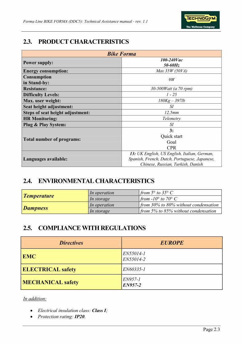
2.6. MECHANICAL CHARACTERISTICS
MECHANICAL CHARACTERISTICS Length (mm | in) 1216mm –48” Width (mm | in) 600mm –24” Height (mm | in) 1338mm –53” Total weight (kg | lbs) 61Kg –134.5lbs
2.6.1. BULK DIMENSIONS

Forma Line BIKE FORMA (DDC5): Technical Assistance manual - rev. 1.1
Page 2.5
2.6.2. PACKING DIMENSIONS EUROPE AND OVERSEAS
Forma Line BIKE FORMA (DDC5): Technical Assistance manual - rev. 1.1
Page 2.6
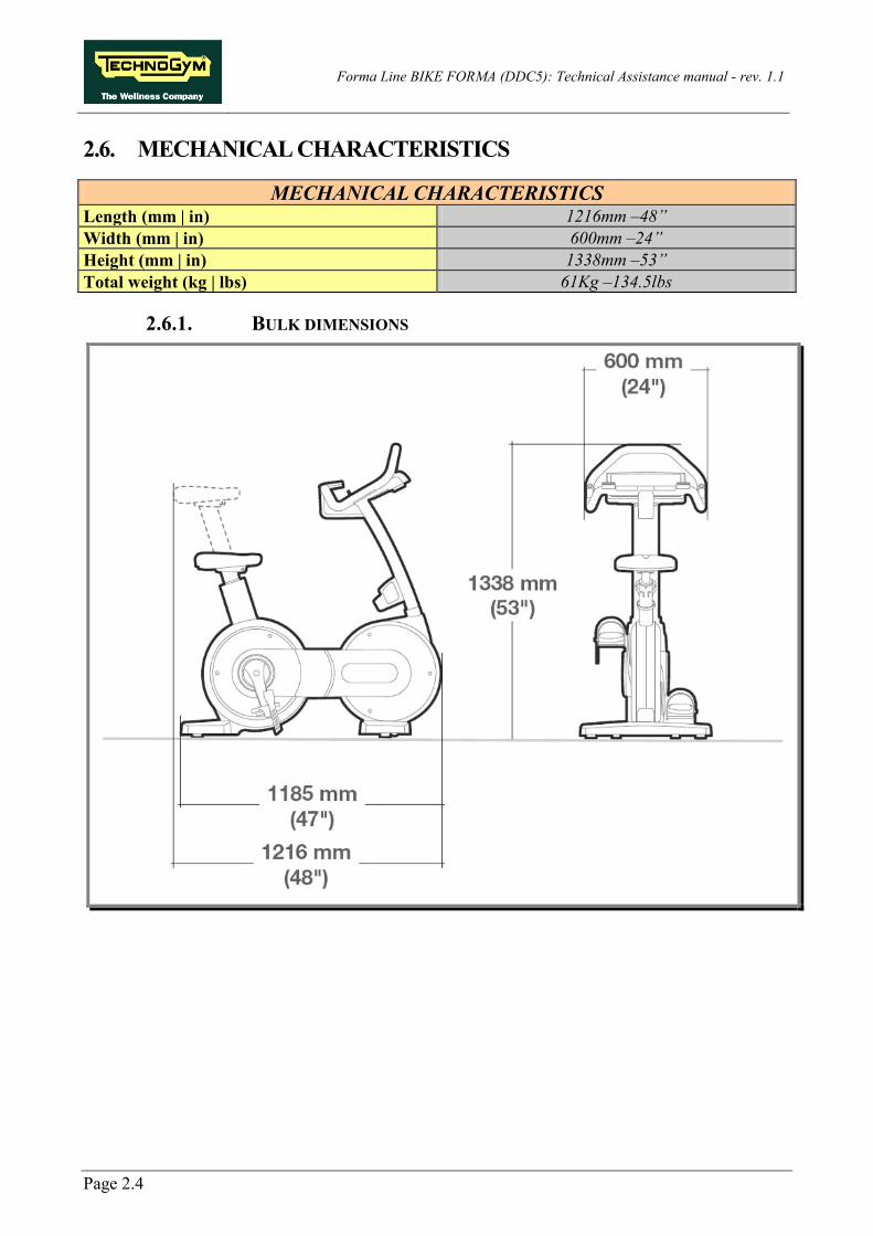
2.7. WIRING DIAGRAM
2.7.1. POWERED MODEL (ARM BOARD)

Forma Line BIKE FORMA (DDC5): Technical Assistance manual - rev. 1.1
Page 2.7
2.8. CABLES
The colour of the cables may change: in particular, refer to the Pin Out.
2.8.1. CBQ CABLES CBQ-13: C-Safe Board Cable (Only LED)
(ARM Board - C-Safe Board) ARM Board
CN8 Signal Colour C-Safe Board CN1
1 Digital #1 Flat cable 1 … … … … 14 Digital #14 Flat cable 14
2.8.2. CU CABLES CU195: Power supply cable for High Kit and Low Kit
(Brake Board - CPU/ARM Board) Brake Board
CN1 Signal Colour ARM Board: CN1 CPU Board: CN15
1 GND Yellow/Green Faston/Eyelet 2 GND -12V White 2 3 GND -5V Yellow 3 4 sensing GND + 5V Pink 4 5 n.c. - 5 6 + 12 Vdc Brown 6 7 + 5 Vdc Green 7 8 sensing + 5V Grey 8
CU196: Serial communication cable for High Kit and Low Kit
(Brake Board - CPU/ARM Board) Brake Board
CN3 Signal Colour ARM Board:CN9 CPU Board:CN18
1 n.c. Orange-White 1 2 n.c. Orange 2 3 n.c. Green-White 3 4 n.c. Blue 4 5 n.c. Blue-White 5 6 n.c. Green 6 7 485 TX/RX + Brown-White 7 8 485 TX/RX - Brown 8

Forma Line BIKE FORMA (DDC5): Technical Assistance manual - rev. 1.1
Page 2.8
CU208: Cable for HR Cardio Receiver
(ARM Board - HR Receiver) ARM Board: CN3 Signal Colour HR Receiver:
CN1 1 Power supply + 5Vdc White 2 7 Impulse (beat to beat) Brown 4 8 Gnd Green 1
CU309: Cable for 100/220V internal power supply signal
(Input module - Brake Board) Input Module Signal Colour Brake Board
CN4 N NEUTRAL Light Blue 1 F PHASE Brown 3 T Earth cable Yellow/Green 5
CU504: Brake power supply cable
(Brake Board - Brake - Speed sensor) Brake Board
CN2 Signal Colour Brake Speed Sensor (magnetic PK)
1 Brake power supply + Brown Faston - 2 Brake power supply - White Faston - 3 R.P.M.Sens. Yellow - Faston 4 GND-RPM Reference Black - eyelet 5 n.c. - - - 6 n. c. - - -

Forma Line BIKE FORMA (DDC5): Technical Assistance manual - rev. 1.1
Page 3.1
3. OPERATING PRINCIPLE
3.1. BLOCK DIAGRAM
The block diagram for the equipment is represented in the following figure:

Forma Line BIKE FORMA (DDC5): Technical Assistance manual - rev. 1.1
Page 3.2
3.2. LED DISPLAY BOARDS
3.2.1. ARM BOARD The Display includes a single board which contains the CPU, an ARM microprocessor, the logic for its operation and the EPROM FLASH containing the equipment's work program, and also acts as a connection centre for all the display components and a connection point with the Brake Board. The main functions of the board are:
manage and process the signals from:
(1) Keyboard; (2) HR Receiver: (3) C-Safe Board;
distribute on the display the supplies it receives from the Brake Board; exchange with the Brake Board the piloting commands for the brake on the RS-485 serial line; manage the LEDs and the 7 display segments to provide feedback on operating.
There are some signal LEDs on the board:
LED Name Colour Description LED1 GREEN if ON, the +12Vdc power supply, provided by the Brake Board, is
reaching the board correctly.
LED2 YELLOW if ON, the +5Vdc power supply, provided by the Brake Board, is reaching the board correctly.
3.2.2. C-SAFE BOARD This is the board that makes available 1 connector for communication between the outside world and the C-Safe compatible devices, such as: Cardio Theater readers. This connector is located at the back of the display. Using a special cable, this connector can be interfaced with an external PC to program the FLASH memory.

Forma Line BIKE FORMA (DDC5): Technical Assistance manual - rev. 1.1
Page 3.3
3.3. CARDIO RECEIVER BOARD
3.3.1. HR (BAND) This is the Board that manages the signal sent by the Telemetric Transmitter (Heart Rate Band), used by the user during training sessions. The Receiver Board receives a power supply of +5Vdc from the Display Board. The Receiver Board communicates with the Display Board using negative logic procedures. When it is in stand-by, the signal has a +5Vdc value and with every heart beat it picks up, it generates an impulse of +0Vdc with an amplitude of 30msec.

Forma Line BIKE FORMA (DDC5): Technical Assistance manual - rev. 1.1
Page 3.4
3.4. BRAKE BOARD
Every Brake Board is divided up into: 1. Power supply section which generates the low voltages used by the equipment: +5Vdc (used
only by high kits of the LED type) and +12Vdc (used by all types of high kits). Depending on the equipment version, these voltage levels are originally generated from mains voltage (both 110Vac and 220Vac) or by a battery-generator.
2. Section that communicates with the Display Board (high kit) on the RS-485 serial line in
order to manage:
the signals for controlling the resistance which needs to be supplied to the Electromagnetic Brake;
the error messages relating to the Electromagnetic Brake; the signals modifying the board's configuration parameters; the signals displaying the memory of errors detected by the board; the signals relating to use of the equipment (RPM, WATT, distance etc..)
3. Section that generates the current for the winding of the Electromagnetic Brake: when the
current varies, the resistance supplied to the Brake itself also varies proportionately. The excitation current supplied to the Brake varies according to the user power/torque requested by the display and the number of revolutions detected by the speed sensor (RPM).
On the Brake Board there are some signal LEDs:
LED Name Colour Description
LED1 GREEN If ON, the board is supplying power to the winding of the brake. If it is FLASHING, there is a fault on the Brake Board and there is no current on the brake.
LED2
YELLOW (if board has supplier code EFI F10549)
If ON, the Brake Board is on. RED (if board has supplier code
LASER F04010)
During movement, the Brake Board is capable of detecting possible faults. Any possible errors are detailed in paragraph: 6.4. “The Brake Board has detected an error”.

Forma Line BIKE FORMA (DDC5): Technical Assistance manual - rev. 1.1
Page 3.5
3.4.1. BRAKE BOARD MODELS Two interchangeable models of Brake Board (LASER and NEW EFI) are used, each is characterized by a specific SW. They can be distinguished from each other by different features on the cover, while the SW is identifiable according to the version of the kernel.
MODELS Brake Board - LASER
(Black plastic box) Brake Board - NEW EFI
(Black plastic box)
Rev. Kernel: 310 Rev. Kernel: 210
You can see, as regards appearance, that: the LASER board (compared with the previous 65W board, which also was in the form of a
black plastic box) has a bevel on one of its sides. the NEW EFI board (as opposed to all the other brake boxes used up to now) has a metal
heat dissipator on one of its sides.
In order to identify the board unequivocally, you should refer to the kernel revision, which can be found on the label that is usually attached to the rear of the box (see example in the figure below).
If it is programmed with an incorrect SW, it causes communication problems between the high kit and the low kit and the following message appears on the display “THE EQUIPMENT IS BLOCKED (COM)”.

Forma Line BIKE FORMA (DDC5): Technical Assistance manual - rev. 1.1
Page 3.6
3.5. ELECTROMAGNETIC BRAKE
It is an eddy current Brake, consisting of a flywheel mass and a flat copper disk which turns in the air gap of a winding. When there is a variation in the current to the winding, the field produced by it also varies and there is a consequent variation in the eddy currents induced in the copper disk and the resistance supplied to the movement of the pedals on the equipment. Two solenoids (Coils of a cylindrical shape consisting of a series of tight coils made with a single thread of conducting material) that are connected in line are provided with a power supply through an adjustable direct current generator, so as to create a more or less intense magnetic field. The inertia disk (flywheel) turns between the coils. Due to the movement, each sector of the disk is crossed by a magnetic field flow that varies in continuation and, as a consequence, electromotive forces are generated which cause the circulation of induced currents. These currents have a direction that is opposite to the element that generated them i.e. the movement of the disk inside the magnetic field itself. As a consequence a braking effect is created which slows down the movement of the disk. The effect increases in intensity according to the size of the magnetic field of the coils and the speed level of the disk. Due to this operating principle, it is clear that when the disk is stationary, the braking effect is non-existent. As opposed to the majority of mechanical brakes, which function by exploiting friction force, here there are no parts subject to wear and tear. The winding has a resistance of about 5Ω (Ohm), so, consequently, the brake absorbs a maximum current of 2.2 A.
3.6. SPEED SENSOR
It consists of a magnetic induction sensor which detects the heads of the screws that fix the disk of the Electromagnetic Brake.
3.7. INPUT MODULE
It is a module consisting of:
• Input power supply socket; • Output power supply socket; • Fuse holder with two rapid 3.15 A fuses to protect the line and the neutral.
It is located on the front platform.

Forma Line BIKE FORMA (DDC5): Technical Assistance manual - rev. 1.1
Page 3.7
3.8. BRAKE COMMAND
3.8.1. THE MECHANICS The movement of the pedals sets the primary shaft into rotation. The primary shaft is attached to the secondary shaft and then to the brake, via a belt. The speed sensor, built into the frame, detects the heads of the screws that fix the disk to the flywheel and generates a signal representing the speed.
3.8.2. CONTROL The control diagram is as follows:
In order to set up a specific exercise difficulty, the Brake Board communicates with the Display Board via the RS-485 serial cable indicating speed value of the exercise in revs per minute (RPM). On the basis of the commands received from the Display Board, the Brake Board sends an excitation current to the winding on the brake which will generate an electromagnetic field.
WARNING: When the Brake Board receives the signal to start the exercise from the Display Board, the green LED comes on and current is supplied to the electromagnetic brake; provided that RPM ≠ 0.
When the Brake Board receives the signal to generate resistance, the green LED comes on.
Due to the electromagnetic field produced by the Current sent from the Brake Board to the winding, and by the rotation of the disk, eddy currents will be induced on the disk itself which will generate a force that will tend to slow down its movement. This will then generate Resistance on the pedals.
Forma Line BIKE FORMA (DDC5): Technical Assistance manual - rev. 1.1
Page 3.8
The higher the value of the Current sent by the Brake Board to the winding, the greater the Resistance produced. In addition, when the excitation of the brake is the same, the higher the speed of the disk rotation, the higher the resistance produced. Heat energy is dissipated on the brake disk due to the eddy currents.
The control over the CURRENT is CLOSED LOOP. The Brake Board calculates which level of current to send to the brake winding, commands for it to be supplied with a special driving circuit, and lastly checks that it is actually reaching the brake through a reading circuit and the A/D conversion of the signal of the current as read.
The control over the RESISTANCE that is actually present on the pedals (effective user torque) is via OPEN LOOP. The system (Brake Board) + (brake) does not envisage any regulation in order to adjust the value of the resistance produced, but solely the use of the braking value table as memorized on the Brake Board. The precision of the braking system has a tolerance of ±10%.
Certain pieces of equipment (e.g. floating ones, but not only those) as opposed to the common training sessions with constant torque and constant power, provide for a training mode with constant speed level. With this kind of training, the Brake Board always operates a CLOSED LOOP control over the CURRENT, but does not operate any control over the RESISTANCE, since it only needs to maintain a constant RPM value. In practice, in addition to the control over the CURRENT, the Brake Board exercises in this case a CLOSED LOOP control over the RPM, since it knows the target value to be achieved. It activates the current to achieve it and constantly reads the RPM value on the speed sensor so as to converge the control.
During movement, the speed sensor detects the heads of the screws that fix the disk of the brake and produces a signal representing the speed, which is sent to the Brake Board. The Brake Board will regulate the excitation current to the winding so that the speed measured by the speed sensor corresponds to the set speed.
If the Brake Board does not receive the speed signal which confirms that an exercise is in progress, the equipment does not produce any resistance (current equal to zero). This occurs mainly for two reasons: the equipment is stationary or there is a problem with the RPM pick up.
During movement, the Brake Board is capable of detecting possible faults. Any possible errors are detailed in paragraph: 6.4. “The Brake Board has detected an error”. In all circumstances, the Brake Board interrupts the supply of current to the brake, the green LED switches from "on" to flashing mode and sends an appropriate error message to the Display Board which visualizes the following message on the display: “THE EQUIPMENT IS BLOCKED. CONTACT THE TECHNOGYM TECHNICAL SERVICE (X)”, where “X” represents the Error Code for the error that has occurred.
Other error codes that may be displayed on the high kit but are not included in the table and are different from (COM), do not relate to the POWERED kind of Brake Board.

Forma Line BIKE FORMA (DDC5): Technical Assistance manual - rev. 1.1
Page 3.9
3.8.3. THE SIGNALS INVOLVED During control, the following signals may occur: • RS-485 Signal
It is a digital signal between the Brake Board and Display Board. We have no possibility of monitoring its state.
• Excitation current This is the current generated by the Brake Board (pin 1-2 of the CN2 connector) and used to power the brake winding. The power supplied is a function of the adjustment algorithm.
• Impulses from the speed sensor (speed sensor or generator, according to the type of equipment) This is the signal produced by the speed sensor and it normally appears as in the following illustration:
Figure 3.8-1
This enters the Brake Board (pin 3-4 on CN2 connector) and here it is used to determine the speed value (RPM) which is sent to the Display Board via the RS-485 serial cable.
This signal can also be measured qualitatively using a multimeter. When the equipment is stationary, the voltage measured on the sensor is 0Vdc, whereas it varies by several hundred mV and more during pedalling: the higher the speed, the greater the value measured.

Forma Line BIKE FORMA (DDC5): Technical Assistance manual - rev. 1.1
Page 3.10
Page blank.

Forma Line BIKE FORMA (DDC5): Technical Assistance manual - rev. 1.1
Page 4.1
4. ACCESSORIES
4.1. CONNECTION TO THE PC FOR PROGRAMMING
The equipment is connected to a PC for programming via the RJ45 connector of the C-Safe Board.
WARNING: in order to identify the numbering of the pins on the RJ45 connector, you should refer to the following diagram:
While programming the equipment, sometimes you need to use an RJ45 plug on the vacant RJ45 port on the back of the display, to avoid interference of any kind during the operation.
The diagram of the RJ45 plug is as follows:
The RJ45 connection cable and plug are both available by ordering code R0002534AB.

Forma Line BIKE FORMA (DDC5): Technical Assistance manual - rev. 1.1
Page 4.2
4.2. MONITOR PLUG FOR C-SAFE PORT
By inserting the plug - code number 0WC00639AA - into the C-Safe port on the equipment, the LED mounted on it must come on as a signal that the 5Vdc is reaching the port. During the test function for the C-Safe ports, the plug allows the transmission channel to be diverted onto the reception channel, thereby obtaining a positive result for the test if the port is functioning.

Forma Line BIKE FORMA (DDC5): Technical Assistance manual - rev. 1.1
Page 5.1
5. INSTALLATION INSTRUCTIONS
5.1. INSTALLATION
In order to install the equipment correctly, you need to proceed as follows: 1. The equipment is installed on a flat surface, where there are no vibrations and adequate weight
capacity also taking into consideration the weight of the user. 2. The environment must not be dusty or sandy. 3. The requirements regarding temperature and humidity levels must be complied with. See
paragraph: 2.4. “Environmental Characteristics”. 4. The equipment must not be placed near heat sources or sources causing electromagnetic
disturbance (televisions, electric motors, aerials, high voltage cables, domestic appliances etc...) and medical equipment.
5. In order to eliminate any disturbance on the cardio receiver, no transmitter must be within a distance of 90cm from the display in: Figure 6-1 and Figure 6-2.
6. The mains voltage must be the same as the voltage indicated on the equipment label. 7. The electric circuit must have a good earth connection. 8. The electricity socket must be used exclusively for the equipment and have a power of at least
100VA. 9. Connect a maximum number of pieces of equipment in cascade according to the information in
paragraph: 3.7. “Input Module”. 10. Place the power supply cable so that it will not get in anyone's way. 11. According to which country the equipment is going to, it may be sent partially assembled, sealed
within its cardboard packaging and fixed onto a pallet, or it may be fully assembled within a transparent plastic wrap, fixed onto a wooden pallet.
Follow the assembly operations shown in the instruction sheets attached to the equipment.
12. Connect the power supply cable to the equipment. 13. Position the start switch on position 0. 14. Connect the power supply cable to the socket.

Forma Line BIKE FORMA (DDC5): Technical Assistance manual - rev. 1.1
Page 5.2
5.2. HANDLING THE EQUIPMENT
In order to move the equipment from the packing pallet to the floor, you should lift it as indicated in the figure and then slide it to the ground.
Considering its weight, we suggest that at least 2 people help with moving the equipment.
WARNING: When moving and positioning the equipment on the ground, great care must be taken because the equipment could easily lose stability.
1. The equipment is equipped with fixed front wheels. In order to move it, you need to lift it slightly, as shown in the figure, and push it forwards or backwards.
Figure 5.2-1
Figure 5.2-2
Once the equipment is placed in its working position, you can regulate the height of one or two of the equipment's feet in order to get it level, as indicated in paragraph: 8.6. “The equipment is not level”.
2. If the conditions of the floor do not allow the wheels to be used, the equipment can be moved
by using normal lifting and transport equipment.

Forma Line BIKE FORMA (DDC5): Technical Assistance manual - rev. 1.1
Page 5.3
5.3. FIRST START-UP
After completing the installation procedure the equipment is ready for use. On POWERED models, all you need to do to start the equipment is turn the start switch from position 0 to position 1. When it starts up, the equipment performs a Check-Up between the High Kit and Low Kit. At the end, the equipment goes into Stand-By position while waiting for a command from the keyboard. In order to check that the equipment functions correctly:
• Get on the equipment and start an exercise; • Check that the speed indicator varies; • Check that the hardness of the exercise and the level of difficulty varies from 1 to 25, when
you press the difficulty level“+” and “−” buttons on the keyboard; • Put on the cardio transmitter and check that the equipment reads your heart beat rate
correctly.

Forma Line BIKE FORMA (DDC5): Technical Assistance manual - rev. 1.1
Page 5.4
Page blank.

Forma Line BIKE FORMA (DDC5): Technical Assistance manual - rev. 1.1
Page 6.1
6. TROUBLESHOOTING The troubleshooting procedures are shown on flow charts. In order to make reading easier, the following standards have been adopted:
START
This box is the point of departure, where you start your troubleshooting procedure. These boxes usually include a description of the type of problem.
Decision
This box is a phase in the troubleshooting procedure, where a test needs to be done. This box usually has a detailed description of the type of TEST to be done. On the basis of the test results, you come out with a positive (YES) or negative (NO) answer.
Action
This box is a phase in the troubleshooting procedure, where an ACTION needs to be taken. This box usually has a detailed description of the type of ACTION to be taken, which should be the one to resolve the problem. Therefore after taking this ACTION, we advise you to: 1. Check that the problem has been solved; 2. If the problem persists, we would recommend that you
continue to follow the procedure from the point where you left it in order to perform the action.
Note
Detail regarding the operation in progress or those that will come later.
1
When a box with a circled number appears next to the box in the procedure, as in the figure at the side, you will find, at the end of the flow chart, a detailed explanation of the operations to be performed for the test or action described inside the box.
A
A box with a circled letter, like the one in the figure at the side, highlights a point in the procedure, which is typically used in page changes as a sign of continuity.

Forma Line BIKE FORMA (DDC5): Technical Assistance manual - rev. 1.1
Page 6.2
6.1. TROUBLESHOOTING MENU
This section allows to check the proper functioning of some components (Low Kit, LED Display, keyboard, serial ports). Press the 369 keys at the same time when the machine is in stand by, to enter.
The Display will show:
ENTER PASSWORD:
In order to access the procedure you need to enter the password 2501 which protects against unauthorised accesses and press the ENTER key in order to confirm. At this point two choices are offered:
1 = Tech Config , 2 = Troubleshooting
Press the numerical key 2 to enter the Troubleshooting menu and the equipment will start to display the current configuration structure as detailed later on.

Forma Line BIKE FORMA (DDC5): Technical Assistance manual - rev. 1.1
Page 6.3
MAN.KEYBOARD TEST
TROUBLESHOOTING
I2C Dev ices Test
AUTOMATIC TEST MANUAL TEST
LED Test
SERIAL PORTS TEST
CSaf e COM Test
TGS COM Test
Low Kit COM Test
Use the ENTER key to scroll from one parameter to another saving the data if modified, whereas with the + and – speed keys, you can scroll from one parameter to another without saving data; to cancel the operation, press the CANCEL key for a few seconds.
The available tests are split into two groups: Automatic and Manual, and the choice is proposed as soon as the troubleshooting menu is accessed.
6.1.1. AUTOMATIC TESTS The tests that the equipment proposes in this section perform checks in a wholly automatic manner. After selecting the item for the test you require by using the + and - difficulty level keys, you activate it by pressing the ENTER key and wait for the result. Press ENTER again in order to continue and use the CANCEL key to return to the superior level, by holding it down for a few seconds. The various tests are detailed below:
6.1.1.1. I2C Devices Test The I2C Devices test is used to test the connection with the 32K and 256K memories. The test can have the following results:
• “Test Successful, press Enter to continue”: It means that the transmission and reception of data packs by the I2C devices to the Display Board were successful.
• “EEPROM Error, press Enter to continue”: It means that the Display Board has some communication problems with the memories.

Forma Line BIKE FORMA (DDC5): Technical Assistance manual - rev. 1.1
Page 6.4
6.1.1.2. LED Test The LED test checks on the functioning of all the LEDs in the display by turning on all the matrices. The BUZZER is also tested by varying the frequency which causes a variation in the tone of the sound. The test does not issue any message with the test results, so you need to check the outcome visually.
6.1.1.3. Serial Ports Test The serial ports test performs a communication check on the connection ports using:
• C-Safe COM test; • Low Kit COM test; • TGS COM test.
By using the + and - difficulty level keys, select the test you require and confirm your choice by pressing the ENTER key. The test can produce two results: • “Test Successful, press Enter to continue”: This means the test was successful and that the
communication with the selected serial port is correct. • “COMx error, press Enter to continue”: This means the test was a failure and the term COM1
will be displayed if the communication test related to the C-Safe COM test, COM2 if relating to communication with the Low Kit and COM3 if relating to communication of the TGS COM test.
A “TGS COM test” performed on equipment that does not have a TGS reader will have a negative result as will a “C-Safe COM test” if the equipment is not connected to the monitor plug indicated in paragraph: 4.2. “Monitor plug for C-Safe port”.
6.1.2. MANUAL TEST The tests that the equipment proposes in this section perform manual checks on some of the peripheral devices. After selecting the item for the test you require by using the + and - difficulty level keys, you access the test by pressing the ENTER key. To quit the test phase you press the CANCEL for a few seconds.
6.1.2.1. Man. Keyboard Test The keyboard manual test runs a check on all the keys on the keyboard. Once you have accessed the test by pressing the ENTER key, a message will appear, saying “Press all buttons (beep=OK)”. When you press each key a "beep" is produced but if a key fails to produce a "beep", it means it does not work.
Forma Line BIKE FORMA (DDC5): Technical Assistance manual - rev. 1.1
Page 6.5
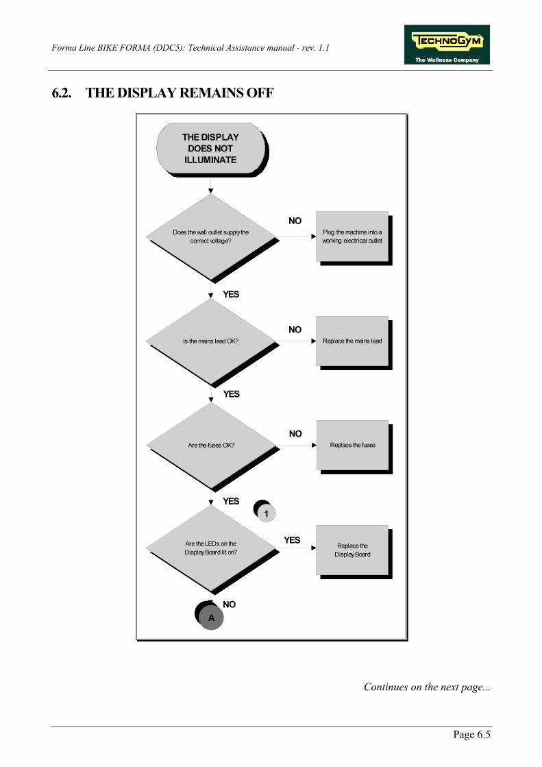
6.2. THE DISPLAY REMAINS OFF
Does the wall outlet supply the correct voltage?
Is the mains lead OK?
Are the LEDs on theDisplay Board lit on?
Plug the machine into a working electrical outlet
Replace the mains lead
Replace theDisplay Board
THE DISPLAY DOES NOT
ILLUMINATE
NO
YES
NO
YES
NO
YES
A
1
Are the fuses OK? Replace the fuses
YES
NO
Continues on the next page...

Forma Line BIKE FORMA (DDC5): Technical Assistance manual - rev. 1.1
Page 6.6
2
Chack the cable that connect the Low Kit
with High Kit.
YES
NO
Is the voltage at the input of the Brake Board
correct?
NO
YES
ReplaceCU309 cable
NO Replace the power entry module
YES
Are the voltages at the output of the Barke Board
correct?
NO
Replace the Brake Board
4
A
3
Is the voltage at the output of the power entry
module correct?
Follow the chart step by step in order to make a correct diagnosis. In particular, pay attention to the checks highlighted in the numbered boxes and listed here below:
(1) Check that LEDs 1 and 2 (green and yellow) are lit on the Display Board. (2) Insert the tips of the tester onto pins 3 and1 of the CN4 connector on the Brake Board. They
should register about 220Vac or 110Vac according to the mains voltage. (3) Gently lift the fastons on the power supply socket on the equipment. Insert the tips of the
tester between the phase and neutral on the connector. They should register about 220Vac or 110Vac according to the mains voltage.
(4) Using the tester, measure the voltages on the CN1 connector on the Brake Board. They must register:
• +12 Vdc between pins 6-2; • +5 Vdc between pins 7-3.
If the Display Board is replaced, check that the upgraded SW version is installed or proceed with the upgrade.
If the Brake Board is replaced, check that the correct SW version is installed or proceed with the upgrading of the Firmware (FW), the Brake Table and the Standard Settings.

Forma Line BIKE FORMA (DDC5): Technical Assistance manual - rev. 1.1
Page 6.7
6.3. THE DISPLAY SHOWS THE MESSAGE “THE EQUIPMENT IS BLOCKED (COM)”
The (COM) error indicates that there is no communication between the two KITs. This may occur essesntially in the following cases: 1. Interruption in communication on the serial line between the Display Board (High Kit) and the
Brake Board (Low Kit): communication cabling is defective, replace cabling;
2. The SW of the Brake Board Firmware (FW) and/or the Brake Table is incorrect /corrupt: example where the operator manually loads the FW and chooses the wrong one. The solution is to re-load the Firmware (FW) (an action which is always possible for any Brake Board);
3. The SW of the Display Board is incorrect /corrupt: the High Kit SW has not been upgraded -
proceed with upgrading. The error is displayed with a message on the display and recorded in the “Errors Log” section. In order to re-instate communication between the High Kit and the Brake Board, proceed as follows: (1) Check that the Serial Communication Cable (CU196) is intact, by using the Test Box Excite
and if necessary, replace it. (2) Upgrade the SW on the Brake Board by loading: the Firmware (FW) and the Brake Table
and run the Standard Setting. (3) Upgrade the SW on the Display Board. (4) Try and replace the Brake Board and the Display Board one at a time and check whether the
serial communication is re-enabled (you can use a standard network cable for the test).
If the Display Board is replaced, check that the upgraded SW version is installed or proceed with the upgrade.
If the Brake Board is replaced, check that the correct SW version is installed or proceed with the upgrading of the Firmware (FW), the Brake Table and the Standard Settings.

Forma Line BIKE FORMA (DDC5): Technical Assistance manual - rev. 1.1
Page 6.8
6.4. THE BRAKE BOARD HAS DETECTED AN ERROR
When the Brake Board detects an error, it blocks by interrupting the power supply and memorizes a numeric code in its memory which identifies the detected error. In addition it sends a signal regarding the status of the error to the DISPLAY Board, via the serial line. When the DISPLAY Board receives this signal, it interrupts the exercise and displays the following message on the screen “THE EQUIPMENT IS BLOCKED”. The errors memorized on the Brake Board can be displayed as illustrated in paragraph: 9.2.3. "Errors Log”. The following table provides information regarding error codes, meanings and possible solutions: Error Code Description Meaning Solution
0 Not used. -
Upgrade the Firmware (FW) on the Brake Board. If the same errors occur after upgrading has been successfully completed, the problem is NOT the Brake Board.
1 Electrical Overtemperature.
Overtemperature error - internal NTC. This error occurs when the temperature measured by the internal NTC probe exceeds 90°C (OLD EFI board), 110°C (NEW EFI board) or 105°C (Laser board). In this case the board passes into fault status and the error is recorded in the error log.
Switch off the equipment and switch it back on again. If the error persists, replace the Brake Board.
2 Trip overcurrent brake kit.
Trip overcurrent error. Equipment that only provides for constant RPM training sessions (e.g. STEP/WAVE) does not perform this control. With equipment that provides various kinds of training, the control for this error is not performed if the selected training is of the constant speed type. The error occurs when the current on the brake suddenly rises. The trip overcurrent condition happens if the level of braking current corresponds to 150% of the maximum value taken from the braking table, for 5 consecutive iterations of the brake control algorithm. In this case the error must be recorded in EEPROM and the equipment must be placed in fault.
Switch off the equipment and switch it back on again. If the error persists, replace the Brake Board.
Continues on the next page...

Forma Line BIKE FORMA (DDC5): Technical Assistance manual - rev. 1.1
Page 6.9
Error Code Description Meaning Solution
4 Not used. -
Upgrade the Firmware (FW) on the Brake Board. If the same errors occur after upgrading has been successfully completed, the problem is NOT the Brake Board.
8 Overvoltage
Overvoltage error. The overvoltage error only occurs for powered equipment when the Vout voltage exceeds 14.0V and is memorized in the error log.
The error relates to the Powered EFI board (therefore it is not codified for the Self-Powered EFI board or the Powered Laser board).
16 Opening of Klixon coil.
Error in opening of Klixon coil (or brake circuit in general). This error must be checked with all kinds of brake. If the Klixon is integrated in line on the brake, it means that its opening has taken place. If the brake does not include a Klixon (e.g. a 2 A brake), this means in general that a hardware error has occurred that does not allow the brake to be controlled. After verifying that the braking current is zero against a braking current control other than zero, the control unit goes into fault and saves the event in the error log. The control is performed for any kind of training and only for control duty cycle of the brake above 20%: the error condition is verified if the control provides a positive result for 5 consecutive iterations.
Check that the cabling on the electromagnet is correct.
32 CRC fault on the braking table.
CRC fault error on the braking table. This occurs when the installed braking table has an erroneous CRC. It is saved in the error log. This control is not performed for equipment which only provides for constant RPM training sessions (e.g. STEP/WAVE).
Re-load the braking table.
Continues on the next page...

Forma Line BIKE FORMA (DDC5): Technical Assistance manual - rev. 1.1
Page 6.10
Error Code Description Meaning Solution
64 EEPROM Fault.
Corrupt EEPROM. This happens when the flag relating to the CURRENT zone and the flag relating to the MIRROR zone (in EEPROM) indicate results that are not consistent.
Re-load the braking table.
128 Not used. -
Upgrade the Firmware (FW) on the Brake Board. If the same errors occur after upgrading has been successfully completed, the problem is NOT the Brake Board.
Forma Line BIKE FORMA (DDC5): Technical Assistance manual - rev. 1.1
Page 6.11
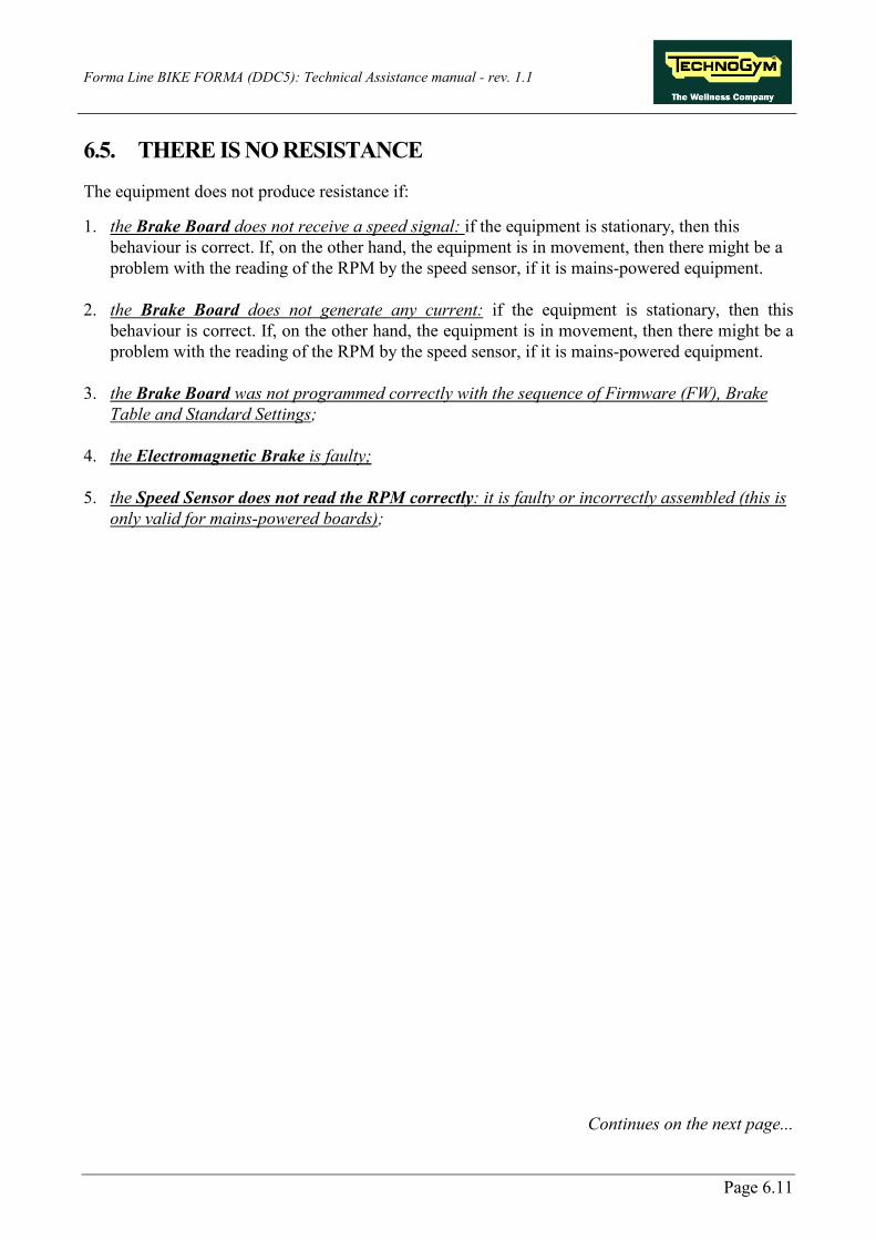
6.5. THERE IS NO RESISTANCE
The equipment does not produce resistance if: 1. the Brake Board does not receive a speed signal: if the equipment is stationary, then this
behaviour is correct. If, on the other hand, the equipment is in movement, then there might be a problem with the reading of the RPM by the speed sensor, if it is mains-powered equipment.
2. the Brake Board does not generate any current: if the equipment is stationary, then this
behaviour is correct. If, on the other hand, the equipment is in movement, then there might be a problem with the reading of the RPM by the speed sensor, if it is mains-powered equipment.
3. the Brake Board was not programmed correctly with the sequence of Firmware (FW), Brake
Table and Standard Settings; 4. the Electromagnetic Brake is faulty; 5. the Speed Sensor does not read the RPM correctly: it is faulty or incorrectly assembled (this is
only valid for mains-powered boards);
Continues on the next page...

Forma Line BIKE FORMA (DDC5): Technical Assistance manual - rev. 1.1
Page 6.12
YES
YES
YES
YES
Does the Brake Board supply tension at the brake?
THERE IS NO RESISTANCE
Are the Watt and RPM values shown on the display different
from zero?
NO
1
Carry out the "The speed signal RPM is incorrect"
troubleshooting procedure
OK
There is the tension at the input of the Brake?
NO
Replace the BrakeReplace connecting cable
NO
3
Is the resistance on the Brake winding more or less 5Ohm?
Replace the BrakeNO
2
Someone is training?NO
OKproper operation
Reinstall the latest version of Firmware (FW), Brake Table and carry out the Standard
Setting.Working?
NO
Replace the Brake Board
YES
YES
Continues on the next page...

Forma Line BIKE FORMA (DDC5): Technical Assistance manual - rev. 1.1
Page 6.13
Follow the chart step by step in order to make a correct diagnosis. In particular, pay attention to the checks highlighted in the numbered boxes and listed here below: (1) Measure the voltage leaving the Brake Board on pins 1 and 2 of the CN2 connector by
maintaining a constant 60Rpm and increasing the level of difficulty: the Vdc measurement must increase.
(2) Measure the resistance on the two fastons on input to the Brake, with the equipment stationary.
(3) Same as point (1) but reconnecting what was disconnected and on the winding of the Electromagnetic Brake.
If the Brake Board is replaced, check that the correct SW version is installed or proceed with the upgrading of the Firmware (FW), the Brake Table and the Standard Settings.

Forma Line BIKE FORMA (DDC5): Technical Assistance manual - rev. 1.1
Page 6.14
6.6. THE RESISTANCE IS NOT CORRECT
The equipment produces an incorrect resistance if:
1. the mechanics are not perfect; 2. the speed as measured is not correct; 3. the Brake Board is faulty; 4. the Brake Board was not programmed correctly with the sequence of:
a. Firmware (FW), b. Brake Table; c. Standard Settings.
5. the Electromagnetic Brake is faulty.
Are the mechanics of the machine in good condition?
Does the Brake Board output the correct current to the brake
winding?
Replace theBrake Board
NOReplace the Brake winding
HE RESISTANCE IS INCORRECT
2
Repair the f aulty mechanical parts
NO
Carry out the "Speed signal is Incorrect"
troubleshooting procedure
3
Install the latest v ersion of Firmware (FW), Brake Table and carry out the Standard
Setting.
1
YES
YES

Forma Line BIKE FORMA (DDC5): Technical Assistance manual - rev. 1.1
Page 6.15
Follow the chart step by step in order to make a correct diagnosis. In particular, pay attention to the checks highlighted in the numbered boxes and listed here below: (1) Carry out the Standard Settings, as described in the paragraph: 9.2.4. “Standard settings”. (2) Check that the mechanical system consisting of pedals, belt and Brake is fluid and does not
provide resistance and friction above the norm. (3) Measure the voltage that the Brake Board provides at the winding. In the Rapid Start-up
mode, set the level of difficulty and check that the value is different from 0.
If the Brake Board is replaced, check that the correct SW version is installed or proceed with the upgrading of the Firmware (FW), the Brake Table and the Standard Settings.

Forma Line BIKE FORMA (DDC5): Technical Assistance manual - rev. 1.1
Page 6.16
6.7. THE SPEED SIGNAL IS NOT CORRECT
The speed signal is not correct if:
1. The disk of the Electromagnetic Brake is incorrectly mounted on the flywheel; 2. The special speed measurement screws are missing or badly assembled (only for
Crossover) 3. The Speed Sensor (for the mains-powered boards) and the Generator (for the self-powered
boards) is defective or badly assembled; 4. the Brake Board was not programmed correctly with the sequence of:
a. Firmware (FW), b. Brake Table; c. Standard Settings.
5. The Brake Board is faulty.
YES
YES
YES
Does the speed sensor send the correct signal to the
Brake Board?
3
Reassembly in the right way
NO
Replace the Brake Board
THE SPEED SIGNAL IS INCORRECT
1
Update the Low Kit SW.Is the speed signal correct?
Instal the latest v ersion of Firmware (FW), Brake Table and carry out the
Standard Setting
NO
Carry out the Standard Setting procedure
2
Are the detection screws present and/or assembled in
the right way ?
Replace the speed sensor
(generator on SP models)
NO
YES

Forma Line BIKE FORMA (DDC5): Technical Assistance manual - rev. 1.1
Page 6.17
Follow the chart step by step in order to make a correct diagnosis. In particular, pay attention to the checks highlighted in the numbered boxes and listed here below: (1) Carry out the Standard Settings, as described in the paragraph: “STANDARD SETTINGS”. (2) Mains-powered equipment: Insert the tips of the tester on the ends of the speed sensor. If
you have an oscilloscope, the signal that should be measured is like the one indicated in Figure 3.8-1, at about 80rpm user.
The speed signal can also be measured in a qualitative manner using a multimeter. When the equipment is stationary, you should register a value of 0Vdc, which will tend to grow as the speed increases.
With mains-powered equipment, the Speed Sensor detects the heads of the screws that fix the copper disk to the flywheel (this is valid for all pieces of equipment except Crossover, which also has the disk fixing screws, but the speed measurement is performed on other screws fixed on the flywheel).
(3) Perform a Low Kit SW Update, by first loading the Firmware (FW) and then the Brake Table. At the end of the operation, launch the Standard Settings, to update the Low Kit parameters.

Forma Line BIKE FORMA (DDC5): Technical Assistance manual - rev. 1.1
Page 6.18
6.8. THERE IS NO HEART FREQUENCY SIGNAL
6.8.1. HR RECEIVER (HEART RATE BAND)
THERE IS NO HR SIGNAL
(Chest Belt)
Check if the +5Vdc are at the input of the Receiver Board.
Are them present?
ARM/CPU Board defective.Replace.
3
NO
SI
Check if the +5Vdc are at the output of the ARM/CPU Board.
Are them present?
4
NO
Receiver Boarddefective.Replace.
Check the SW and the groundin of Receiver Board.Problem persists?
Place correclty
1
YES
NO
Check the proper functioning of the Receiver Board.
Is proper placed?
OK
2
NO
NO
YES
YES
Check if it works properly using a chest belt you are sure it's ok.
The problem solved?
Chest Belt defective
SIReplace the connecting cable between the High
Kit and the Low Kit.
YES
YES
Continues on the next page...

Forma Line BIKE FORMA (DDC5): Technical Assistance manual - rev. 1.1
Page 6.19
Follow the chart step by step in order to make a correct diagnosis. In particular, pay attention to the checks highlighted in the numbered boxes and listed here below: (1) Check on the correct SW version, according to the “EXCITE SW SMART TABLE” table
found in the TG Direct. (2) Check on the correct positioning of the Receiver Board as indicated in paragraph: 7.4.
"Dismantling the Cardio Receiver” “HR Receiver (Band)”. (3) Insert the tips of the tester onto pins 1 and 2 on the CN1 connector on the receiver. They must
register +5Vdc. (4) Do the same as in point (3) but between pins 1 and 8 on the CN3 connector of the CU208.
If the Display Board is replaced, check that the upgraded SW version is installed or proceed with the upgrade.

Forma Line BIKE FORMA (DDC5): Technical Assistance manual - rev. 1.1
Page 6.20
6.9. TELEMETRIC SIGNAL OF HEART RATE IS NOT CORRECT
6.9.1. HEART RATE BAND
CORRECT USE OF BAND: Place the heart-rate band on the chest in direct contact with the skin and make sure that it is moist in the contact area.
THE TELEMETRIC HR SIGNAL IS INCORRECT
(Chest belt)
Are the machines correctly spaced by the required minimum
distance?
Check the Receiver Board has been correctly mounted on the
machine.
Reposition the machines so they are adequately
spaced
Mount the Receiver Board in the right way
NO
YES
NO
Check the Display SW versione and the grounding of the
receiver.1
2
Chest belt defectiveNO
NO
YES
A
Check if it works properly using a chest belt you are sure it's ok.
The problem persists?
3
YES
Continues on the next page...

Forma Line BIKE FORMA (DDC5): Technical Assistance manual - rev. 1.1
Page 6.21
Are there sources of electromagnetic noise near the
receiver?
Receiver Board defective.Replace it.
NO
4
The problem does not depend on the equipment
YES
A
Follow the chart step by step in order to make a correct diagnosis. In particular, pay attention to the checks highlighted in the numbered boxes and listed here below: (1) Check on the correct SW version, according to the “EXCITE SW SMART TABLE” table
found in the TG Direct. Carry out the earth check on the HR Receiver, by measuring the resistance value between the following points with a tester: a. The faston on the HR Bboard and the earth pole on the Power Supply Box; b. The earth pole on the Power Supply Box and the wall socket. The value must be less than 1Ω (Ohm). Lastly check the earth on the wall socket, making sure there are the following voltages:
P – N (phase– neutral) = 220Vac / 110Vac P – E (phase– earth) = 220Vac / 110Vac
N – E (neutral– earth) = 0Vac
Continues on the next page...

Forma Line BIKE FORMA (DDC5): Technical Assistance manual - rev. 1.1
Page 6.22
(2) Comply with the distance and positioning of the pieces of equipment with each other, keeping to the following diagram:
Figure 6-1
The lateral range (130cm) is greater than the frontal range (90cm) even though it covers a tighter area. Position the pieces of equipment, therefore, as shown in the following diagram:
Figure 6-2

Forma Line BIKE FORMA (DDC5): Technical Assistance manual - rev. 1.1
Page 6.23
(3) Check on the correct positioning of the Receiver Board as indicated in paragraph: 7.4. “Dismantling the Cardio Receiver”.
(4) In order to check whether there is electromagnetic noise near the equipment, use the Text Box
Excite as detailed below. You can use one of the following cables as the connection cable between the receiver and the Test Box: ELT-16 (0WC00518AB), CBQ-28 (0WC00390AC) or TRM-28 (0WC00336AC).
TEST BOXEXCITE
RECEIVER
LED
Connecting cable
The circuit switches on the LED for each heart beat and/or disturbance received. In this way, it is possible to assess whether there is any disturbance and what produces it.
Do not move too close to the LED Display with the Test Box Excite, because it is known that this emits interference.

Forma Line BIKE FORMA (DDC5): Technical Assistance manual - rev. 1.1
Page 6.24
Page blank.

Forma Line BIKE FORMA (DDC5): Technical Assistance manual - rev. 1.1
Page 7.1
7. DISMANTLING THE PARTS
7.1. IMPORTANT NOTE ON DISMANTLING
Figure 7.1-1
Figure 7.1-2
DANGER: DO NOT under any circumstances unscrew the screws and nuts highlighted in the figure. During the initial assembling during production of the (X) and (Y) components, the highlighted screws and nuts are tightened, buckling the frame on the fusion component, making them integral with each other. These will together constitute a single frame for the equipment.

Forma Line BIKE FORMA (DDC5): Technical Assistance manual - rev. 1.1
Page 7.2
7.2. DISMANTLING THE CONTROL PANEL
Figure 7.2-1
Switch off the equipment and remove the power supply plug from the wall socket. 1. Unscrew the 4 screws (a) using a medium-
sized Phillips screwdriver.
Figure 7.2-2
2. Remove the keyboard (b) as indicated by the yellow arrows.
Figure 7.2-3
3. Disconnect the flat cable highlighted in the figure.
4. Unscrew the 4 screws (c), using a medium Phillips screwdriver, remove the Display (d).
Continues on the next page...
Forma Line BIKE FORMA (DDC5): Technical Assistance manual - rev. 1.1
Page 7.3
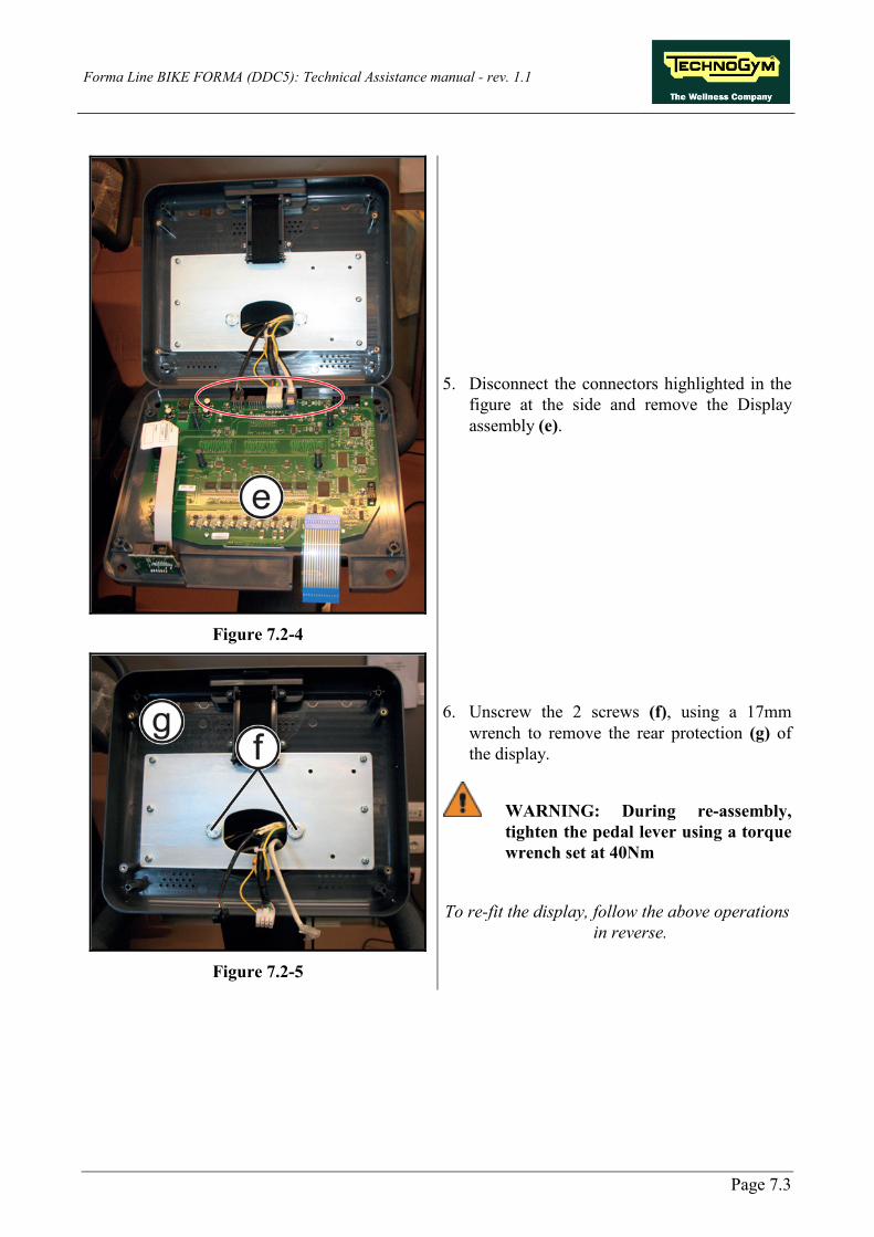
Figure 7.2-4
5. Disconnect the connectors highlighted in the figure at the side and remove the Display assembly (e).
Figure 7.2-5
6. Unscrew the 2 screws (f), using a 17mm wrench to remove the rear protection (g) of the display.
WARNING: During re-assembly, tighten the pedal lever using a torque wrench set at 40Nm
To re-fit the display, follow the above operations
in reverse.

Forma Line BIKE FORMA (DDC5): Technical Assistance manual - rev. 1.1
Page 7.4
7.3. DISMANTLING THE ARM AND C-SAFE BOARD
Figure 7.3-1
Carry out the operations in the paragraph: 7.2. “Dismantling the control panel” up to step 5. Place the control panel on a workbench: Now it is possible to remove the boards it contains:
• The ARM board (a); • The C-Safe board (b).
Figure 7.3-2
Dismantling the ARM board (a): 1. Unscrew the 4 screws highlighted in the
figure at side using a medium-sized Phillips screwdriver.
Figure 7.3-3
Dismantling the C-Safe board (b): 2. Disconnect the flat cable highlighted in the
figure at side. 3. Remove the C-Safe board as indicated by the
yellow arrows.
During the reassembly, use some hot glue to fix the C-Safe board again.
In order to re-fit the Display Boards, carry out the above operations in reverse.
Continues on the next page...

Forma Line BIKE FORMA (DDC5): Technical Assistance manual - rev. 1.1
Page 7.5
After the display reassembling, check that the keyboard correctly works as detailed at paragraph 6.1.2.1 “Man. Keyboard Test”.

Forma Line BIKE FORMA (DDC5): Technical Assistance manual - rev. 1.1
Page 7.6
7.4. DISMANTLING THE CARDIO RECEIVER
7.4.1. HR RECEIVER (BAND)
Figure 7.4-1
1. Unscrew the 3 screws (a) using a medium-sized Phillips screwdriver.
2. Remove the bottom guard (b).
Figure 7.4-2
3. Remove the receiver (c). 4. Cut the strap and remove the sponge
protection (d). 5. Disconnect the receiver from the cables.
To re-fit the receiver, follow the above operations in reverse, considering the following
NOTES:
Continues on the next page...

Forma Line BIKE FORMA (DDC5): Technical Assistance manual - rev. 1.1
Page 7.7
Figure 7.4-3
Re-wrap the receiver in the sponge protection and re-apply a strap to bind it.
1. Connect the cable again to the connector (a)
on the receiver.
Figure 7.4-4
WARNING: Position the receiver so that the coil (b) is turned upwards and towards the user.
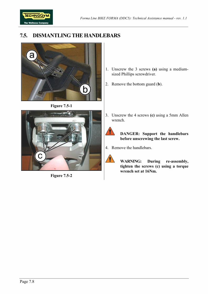
Forma Line BIKE FORMA (DDC5): Technical Assistance manual - rev. 1.1
Page 7.8
7.5. DISMANTLING THE HANDLEBARS
Figure 7.5-1
1. Unscrew the 3 screws (a) using a medium-sized Phillips screwdriver.
2. Remove the bottom guard (b).
Figure 7.5-2
3. Unscrew the 4 screws (c) using a 5mm Allen wrench.
DANGER: Support the handlebars before unscrewing the last screw.
4. Remove the handlebars.
WARNING: During re-assembly, tighten the screws (c) using a torque wrench set at 16Nm.

Forma Line BIKE FORMA (DDC5): Technical Assistance manual - rev. 1.1
Page 7.9
7.6. DISASSEMBLING THE PEDAL AND THE PEDAL LEVER WITH GUARD
Figure 7.6-1
1. Unscrew the threaded pin (a) using a 15mm wrench and remove the pedal.
WARNING: During re-assembly, tighten the screws (a) using a torque wrench set at 32Nm.
Figure 7.6-2
In order to dismantle the pedal lever: 2. Unscrew the cap (b) using snap ring pincers
or with scissors. 3. Unscrew the bolt (c) which you gain access
to, using a 13mm socket wrench. 4. Remove the spacer (d).
Figure 7.6-3
5. Dismantle the pedal lever (e) using a common bicycle pedal remover as shown in the figure.
WARNING: During re-assembly, tighten the pedal lever using a torque wrench set at 40Nm.
To re-fit the pedal and pedal lever, follow the
above operations in reverse.

Forma Line BIKE FORMA (DDC5): Technical Assistance manual - rev. 1.1
Page 7.10
7.7. DISMANTLING THE GUARD
Figure 7.7-1
1. Unscrew the screw (a) using a 4mm Allen wrench.
2. Remove the top guard (b) and fix it with a
strap, as shown in the figure at the side.
Figure 7.7-2
3. Unscrew the 2 screws (c) using a 4mm Allen wrench.
Figure 7.7-3
4. Gently press downwards on the top part of the right-hand guard in order to unhook it from the left-hand one, as shown in the figure.
Continues on the next page...

Forma Line BIKE FORMA (DDC5): Technical Assistance manual - rev. 1.1
Page 7.11
Figure 7.7-4
On the right-hand side: 5. Unscrew the 6 screws (d) using a 4mm Allen
wrench. 6. Line up the pedal in line with the saddle
support, as indicated by the yellow arrow. 7. Remove the right-hand guard.
Figure 7.7-5
On the left-hand side:
After removing the right-hand guard, all you need do for the left-hand side is unscrew the corresponding screws as highlighted in the figure at the side.
Figure 7.7-6
8. Protect the pedal as far as its base using a cloth, as indicated in the figure at the side.
Continues on the next page...

Forma Line BIKE FORMA (DDC5): Technical Assistance manual - rev. 1.1
Page 7.12
Figure 7.7-7
Figure 7.7-8
9. With care, lift the guard slightly (Figure 7.7-7) in order to pass it through the pedal (Figure 7.7-8).
Figure 7.7-9
10. Unscrew the 2 top screws (e) using a 4mm Allen wrench and loosen the 2 side screws.
11. Remove the central support (f). In order to re-fit the guards, carry out the above
operations in reverse.
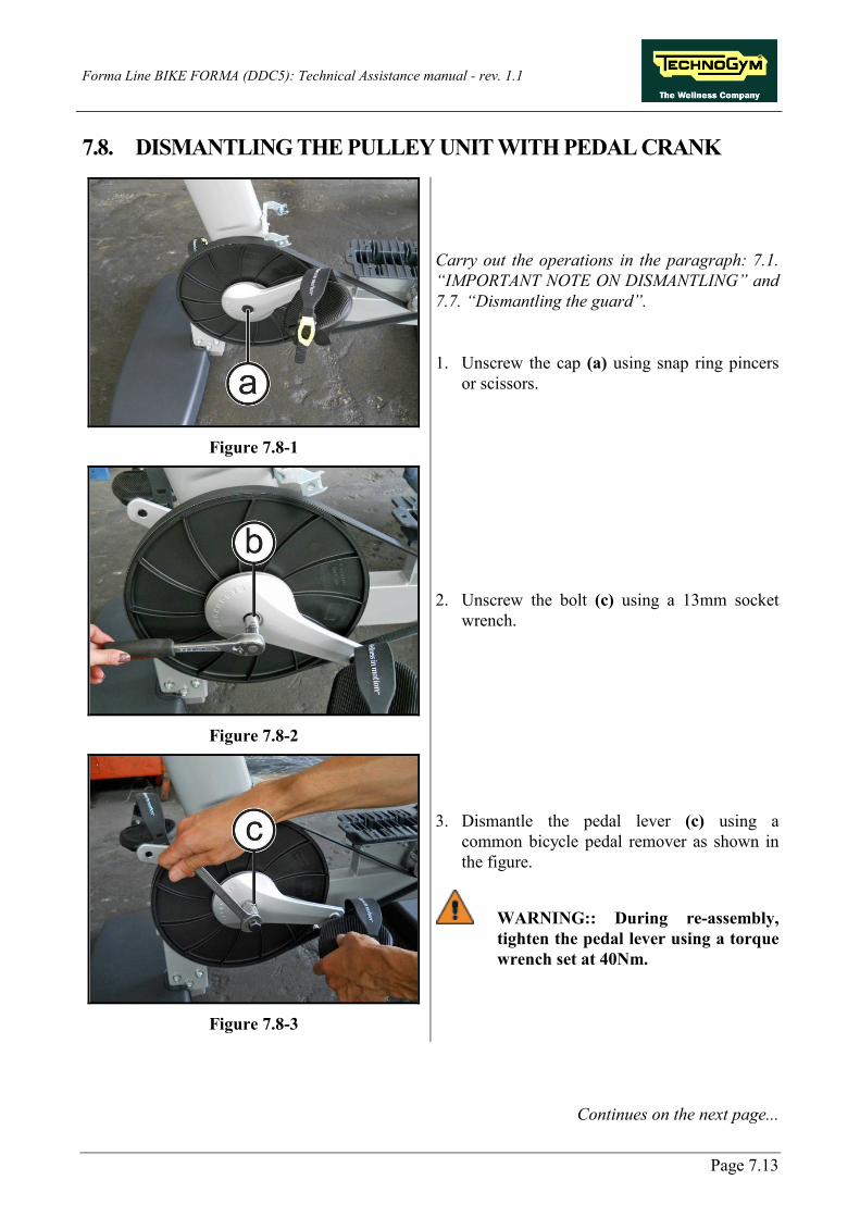
Forma Line BIKE FORMA (DDC5): Technical Assistance manual - rev. 1.1
Page 7.13
7.8. DISMANTLING THE PULLEY UNIT WITH PEDAL CRANK
Figure 7.8-1
Carry out the operations in the paragraph: 7.1. “IMPORTANT NOTE ON DISMANTLING” and 7.7. “Dismantling the guard”. 1. Unscrew the cap (a) using snap ring pincers
or scissors.
Figure 7.8-2
2. Unscrew the bolt (c) using a 13mm socket wrench.
Figure 7.8-3
3. Dismantle the pedal lever (c) using a common bicycle pedal remover as shown in the figure.
WARNING:: During re-assembly, tighten the pedal lever using a torque wrench set at 40Nm.
Continues on the next page...

Forma Line BIKE FORMA (DDC5): Technical Assistance manual - rev. 1.1
Page 7.14
Figure 7.8-4
4. Unscrew the 4 nuts (d) using a 13mm wrench, while blocking the screws on the opposite side, using a wrench of the same size.
WARNING:: During re-assembly, position the screws at the top inside of the flange before refitting the shaft onto the frame.
WARNING: During re-assembly, tighten the screws (d) using a torque wrench set at 22Nm.
Figure 7.8-5
5. On the left-hand side of the equipment, remove the snap ring (3), the spacer (2) and the elastic spring (1).
WARNING:: During re-fitting, take care to re-insert the components according to the sequence shown in the figure.
Figure 7.8-6
6. Remove the pulley shaft (f)from the right-hand side, as shown in the figure.
To re-fit the pulley unit, follow the above operations in reverse.

Forma Line BIKE FORMA (DDC5): Technical Assistance manual - rev. 1.1
Page 7.15
7.9. DISMANTLING THE SEAT
7.9.1. DISMANTLING THE SEAT SUPPORT
Figure 7.9-1
1. Unscrew the 2 screws (a) using a 4mm Allen wrench and slide off the bush.
Figure 7.9-2
2. Give a gentle knock to the bush of the end-of-run (b), raising the seat above its maximum height, so as to facilitate its removal from the frame.
3. Lift the bush (b) by exerting leverage under the housing of the screws, if necessary.
Figure 7.9-3
4. Continue to press on the seat adjustment system under the saddle and slide off the Seat Unit.
Continues on the next page...

Forma Line BIKE FORMA (DDC5): Technical Assistance manual - rev. 1.1
Page 7.16
7.9.2. DISMANTLING THE INTERNAL BUSHING
Figure 7.9-4
1. Lightly force the bushing lever (c) downward and rotate as indicated by the yellow arrow to remove it from its housing.
To re-fit the seat group, follow the above operations in reverse, considering the following NOTES:
Figure 7.9-5
1. When insert the seat tub, keep pressed the seat adjusting system.
2. Place the seat group just above the teethed
guide, as indicated by the yellow arrow. 3. Insert the seat group and carefully slide it
down.

Forma Line BIKE FORMA (DDC5): Technical Assistance manual - rev. 1.1
Page 7.17
7.9.3. DISMANTLING THE SEAT GROUP
7.9.3.1. Dismantling the seat upholstery
Figure 7.9-6
1. Unscrew the 4 screws (a) using a medium-sized Phillips screwdriver.
2. Remove the seat (b).
To re-fit the all what removed, follow the above operations in reverse.

Forma Line BIKE FORMA (DDC5): Technical Assistance manual - rev. 1.1
Page 7.18
7.9.3.2. Dismantling the handle pin
Figure 7.9-7
1. On both the sides, unscrew the screw (a) using a 3mm wrench.
2. Remove the spacers (b) and (c) and the pin (d).
To re-fit the all what removed, follow the above operations in reverse.

Forma Line BIKE FORMA (DDC5): Technical Assistance manual - rev. 1.1
Page 7.19
7.9.3.3. Dismantling the spring and the handle
Figure 7.9-8
Carry out the operations in the paragraph: 7.9.3.1 “Dismantling the seat upholstery”. 1. Use a small-sized flat screwdriver to remove the circlip (a), as indicated by the orange arrow.
Continues on the next page...

Forma Line BIKE FORMA (DDC5): Technical Assistance manual - rev. 1.1
Page 7.20
Figure 7.9-9
2. Remove the pin (b) in the direction of the yellow arrows.
3. Remove the pin (c) as indicated at paragraph: 7.9.3.2 “Dismantling the handle pin”.
Continues on the next page...

Forma Line BIKE FORMA (DDC5): Technical Assistance manual - rev. 1.1
Page 7.21
To remove the handle:
Figure 7.9-10
4. Remove the handle (d) in the direction of the yellow arrow.
Figure 7.9-11
With the seat group on a work bench: 1. Overturn the group.
2. Unscrew the 4 screws (e) using a 7mm socket
wrench.
Continues on the next page...

Forma Line BIKE FORMA (DDC5): Technical Assistance manual - rev. 1.1
Page 7.22
Figure 7.9-12
3. Remove the selector group (f) in the direction of the yellow arrow.
4. Remove the spring (g).
Figure 7.9-13
WARNING: check the spring is correctly mounted to avoid it can easily slip off, as shown in the figure at side.
To re-fit the all what removed
, follow the above operations in reverse.
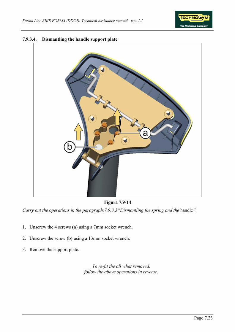
Forma Line BIKE FORMA (DDC5): Technical Assistance manual - rev. 1.1
Page 7.23
7.9.3.4. Dismantling the handle support plate
Figura 7.9-14
Carry out the operations in the paragraph:7.9.3.3“Dismantling the spring and the handle”. 1. Unscrew the 4 screws (a) using a 7mm socket wrench.
2. Unscrew the screw (b) using a 13mm socket wrench.
3. Remove the support plate.
To re-fit the all what removed, follow the above operations in reverse.

Forma Line BIKE FORMA (DDC5): Technical Assistance manual - rev. 1.1
Page 7.24
7.9.3.5. Dismantling the handle pin
Figure 7.9-15
Carry out the operations in the paragraph:7.9.3.3“Dismantling the spring and the handle”.
1. Rotate the lever (a) of 180°, in the direction of the yellow arrow.
2. Slide the lever in the direction of the orange arrow.
Figure 7.9-16
3. Rotate the lever again of 180°, in the direction of the yellow arrow.
Figure 7.9-17
4. Slide the lever in the direction of the orange arrow.
Continues on the next page...

Forma Line BIKE FORMA (DDC5): Technical Assistance manual - rev. 1.1
Page 7.25
Figure 7.9-18
5. Rotate the lever counter-clock wise and free from the support plate.
6. Remove the lever (a).
To re-fit the all what removed,
follow the above operations in reverse.

Forma Line BIKE FORMA (DDC5): Technical Assistance manual - rev. 1.1
Page 7.26
7.10. DISMANTLING THE BELT AND BELT-TENSIONER
Figure 7.10-1
Carry out the operations in the paragraph: 7.1. “IMPORTANT NOTE ON DISMANTLING” and 7.7. “Dismantling the guard”. 1. Make a mark on the initial position. 2. Unhook the spring from the selector. 3. Remove the belt.
Figure 7.10-2
4. Remove the snap ring (a) the underlying washer.
5. Remove the belt-tensioner (b).
Figure 7.10-3
6. Remove the pin (c) using a 6mm Allen wrench.
WARNING:: During re-assembly, tighten the pin (a) using a torque wrench set at 10Nm.
During re-fitting, place some LOCTITE 270 on the threaded side of the pin (c) and grease the part in contact with the belt-tensioner, using MOLYCOTE W2 grease.
To re-assemble the fitting, follow the above operations in reverse and pay attention to the
following notes: Continues on the next page...

Forma Line BIKE FORMA (DDC5): Technical Assistance manual - rev. 1.1
Page 7.27
Figure 7.10-4
As regards the passage of the belt, refer to the figure at the side.
WARNING: At the end of the operation, adjust the tension of the belt as described in the paragraph: 8.1. “Belt tension”

Forma Line BIKE FORMA (DDC5): Technical Assistance manual - rev. 1.1
Page 7.28
7.11. DISMANTLING THE BRAKE AND THE FLYWHEEL UNIT
Figure 7.11-1
Carry out the operations in the paragraph: 7.1. “IMPORTANT NOTE ON DISMANTLING” and 7.7. “Dismantling the guard”. 1. Disconnect the two fastons on the brake
winding, as highlighted in the figure at the side.
2. Unscrew the 2 stop screws (a) using a 4mm
Allen wrench. 3. Remove the brake unit (b) with care.
DANGER: Pay particular attention to the copper disk as it could easily buckle.
WARNING: During re-assembly, tighten the screws (a) using a torque wrench set at 5Nm.
Figure 7.11-2
4. Unscrew the flywheel unit (a) from the central shaft, using a 6mm Allen wrench, while blocking it on the opposite side using a 10mm Allen wrench.
5. With care, remove the flywheel unit from the
side opposite the speed sensor.
WARNING: After re-fitting the flywheel unit, use a comparator to check for any buckling on the copper disk with a margin of ± 0.15mm.
WARNING: During re-assembly, tighten the flywheel using a torque wrench set at 25Nm.
Continues on the next page...

Forma Line BIKE FORMA (DDC5): Technical Assistance manual - rev. 1.1
Page 7.29
Figure 7.11-3
In order to remove the copper disk: 1. Unscrew the 6 screws (d) using a 4mm Allen
wrench. 2. Remove the copper disk (e).
WARNING: During re-assembly, tighten the screws (d) using a torque wrench set at 6Nm.
Figure 7.11-4
To remove the central shaft: 6. In sequence, remove the snap ring (1), the
spacer (2) and the elastic washer (3). 7. Remove the central shaft (f).
To re-assemble the fitting, follow the above operations in reverse and pay attention to the
following note:
WARNING: At the end of the operation, adjust the position of the flywheel, as described in the paragraph: 8.5. “Adjusting the position of the brake unit”.

Forma Line BIKE FORMA (DDC5): Technical Assistance manual - rev. 1.1
Page 7.30
7.12. DISMANTLING THE SPEED SENSOR
Figure 7.12-1
Carry out the operations in the paragraph: 7.1. “IMPORTANT NOTE ON DISMANTLING” and 7.7. “Dismantling the guard”. 1. Unscrew the 2 screws (a) using a medium-
sized Phillips screwdriver. 2. Remove the speed sensor (b).
To re-fit the speed sensor, follow the above operations in reverse.
WARNING: If you also remove the sensor's plastic support, adjust the position of the sensor, as described in the paragraph: 8.4. “Adjusting the position of the speed sensor”.

Forma Line BIKE FORMA (DDC5): Technical Assistance manual - rev. 1.1
Page 7.31
7.13. DISMANTLING THE BRAKE BOARD
Figure 7.13-1
Carry out the operations in the paragraph: 7.1. “IMPORTANT NOTE ON DISMANTLING” and 7.7. “Dismantling the guard”. 1. Remove the Brake Board from the
equipment, gripping it with your hands as indicated by the orange arrows and pull in the direction of the yellow arrows.
2. Remove the Brake Board from its housing.
Figure 7.13-2
3. Disconnect the 3 connectors highlighted in the figure.
4. Unscrew the blocking screw (a) from the
mains power supply connector (b) and disconnect it.
5. Remove the Brake Board (c).
To re-fit the Brake Board, follow the above operations in reverse.
Figure 7.13-3
WARNING: If you replace the Brake Board, be careful not to cover the Board details and the SN with the Velcro adhesive strip.

Forma Line BIKE FORMA (DDC5): Technical Assistance manual - rev. 1.1
Page 7.32
7.14. DISMANTLING THE PLATFORMS
Figure 7.14-1
Front Platform: 1. Unscrew the 4 screws (a) using a medium-
sized Phillips screwdriver. 2. Remove the front platform (b).
Figure 7.14-2
Rear Platform: 3. Unscrew the 6 screws (c) using a medium-
sized Phillips screwdriver. 4. Remove the rear platform (d).
In order to re-fit the Platforms, carry out the above operations in reverse.

Forma Line BIKE FORMA (DDC5): Technical Assistance manual - rev. 1.1
Page 7.33
7.15. DISMANTLING THE INPUT MODULE
Figure 7.15-1
1. To gain access to the connectors, turn the equipment on its side.
2. Unscrew the 2 screws (a) using a medium-
sized Phillips screwdriver and remove the input module on the front platform.
3. Disconnect the connector of the cable which
goes up to the Brake Board, from its support (b).
To re-fit the connectors, follow the above operations in reverse.

Forma Line BIKE FORMA (DDC5): Technical Assistance manual - rev. 1.1
Page 7.34
Blank page

Forma Line BIKE FORMA (DDC5): Technical Assistance manual - rev. 1.1
Page 8.1
8. ADJUSTMENTS
8.1. BELT TENSION
Figure 8.1-1
1. To adjust the belt tension, all you need to do is to choose between the various available positions for the spring (a).
WARNING: The right tension must be between 50 - 60Hz.

Forma Line BIKE FORMA (DDC5): Technical Assistance manual - rev. 1.1
Page 8.2
8.2. ALIGNING THE BELT
Figure 8.2-1
To align the belt: 1. Position it correctly in the races of the small pulley of the flywheel (a) and in the races of the
pulley of the pedal cranks (b).
Pedal a few times going forward and in reverse until the belt is positioned in the centre.

Forma Line BIKE FORMA (DDC5): Technical Assistance manual - rev. 1.1
Page 8.3
8.3. ADJUSTMENT OF THE PLAY ON THE SEAT COLUMN
Figure 8.3-1
1. Raise the seat on the equipment so as to gain access to the adjustment bush.
2. Turn the 2 screws (a) on the bush and adjust
the play of the seat column, using a 3mm Allen wrench.

Forma Line BIKE FORMA (DDC5): Technical Assistance manual - rev. 1.1
Page 8.4
8.4. ADJUSTING THE POSITION OF THE SPEED SENSOR
Figure 8.4-1
1. Loosen the 2 screws (a) using a 3mm Allen wrench.
2. Move the speed sensor support sideways in
the direction of the yellow arrows, moving it closer to or further away from the copper disk up to a distance from the screws of 0.7mm.
3. Re-tighten the screws (a).

Forma Line BIKE FORMA (DDC5): Technical Assistance manual - rev. 1.1
Page 8.5
8.5. ADJUSTING THE POSITION OF THE BRAKE UNIT
Figure 8.5-1
1. Disconnect the 2 fastons highlighted in the figure.
Figure 8.5-2
2. Loosen the 2 screws (a) using a 4mm Allen wrench.
3. Move the Brake Unit sideways in the
direction of the yellow arrows up to a distance from the disk of 0.6mm.
4. Re-tighten the screws (a).
WARNING: In order to adjust the brake correctly, do some pedalling at high speed to check that there is no contact with the flywheel.
DANGER: Using a comparator, measure the planarity of the copper disk. It must have a margin of ± 0.15mm.

Forma Line BIKE FORMA (DDC5): Technical Assistance manual - rev. 1.1
Page 8.6
8.6. THE EQUIPMENT IS NOT LEVEL
This problem may be due to the positioning of the equipment on an unflat surface. In order to resolve the problem, you need to regulate the adjustment foot.
Figure 8.6-1
In order to make the equipment level, adjust the two front and rear feet. 1. Loosen the locknut (B), then tighten or unscrew the foot (A) until the frame is stable. 2. When you have finished the adjustment, tighten the locknut (B).
WARNING: During re-assembly, tighten the nuts (b) using a torque wrench set at a maximum of 35Nm.
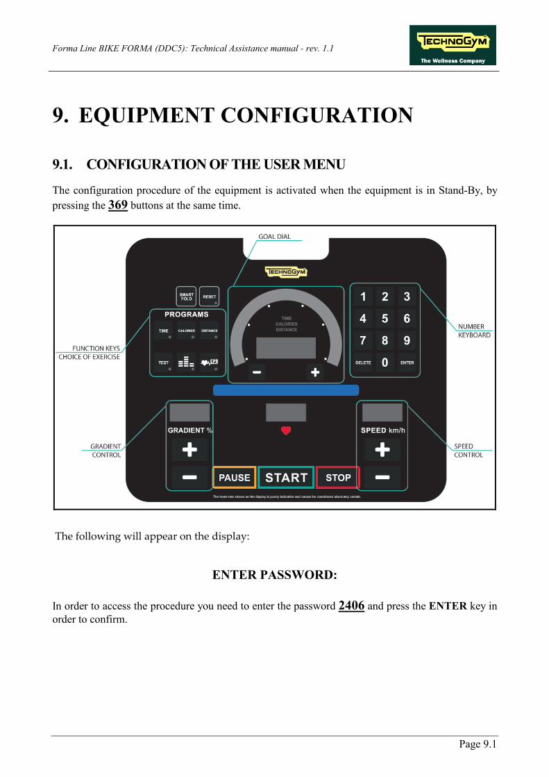
Forma Line BIKE FORMA (DDC5): Technical Assistance manual - rev. 1.1
Page 9.1
9. EQUIPMENT CONFIGURATION
9.1. CONFIGURATION OF THE USER MENU
The configuration procedure of the equipment is activated when the equipment is in Stand-By, by pressing the 369 buttons at the same time.
The following will appear on the display:
ENTER PASSWORD:
In order to access the procedure you need to enter the password 2406 and press the ENTER key in order to confirm.

Forma Line BIKE FORMA (DDC5): Technical Assistance manual - rev. 1.1
Page 9.2
At this point, the equipment starts to show on the display the current configuration, structured like the following diagram:
Use the ENTER key to scroll from one parameter to another saving the data if modified, whereas with the + and – speed keys, you can scroll from one parameter to another without saving data; to cancel the operation, press the CANCEL key for a few seconds.
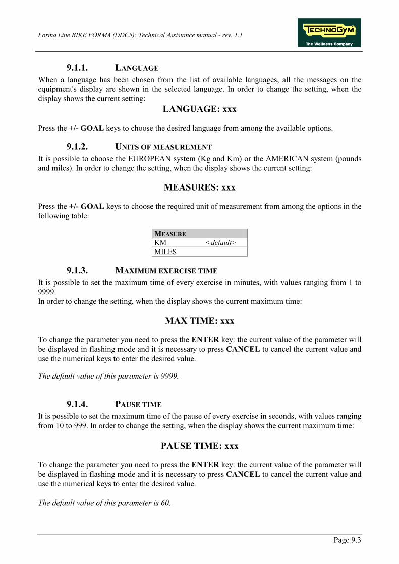
Forma Line BIKE FORMA (DDC5): Technical Assistance manual - rev. 1.1
Page 9.3
9.1.1. LANGUAGE When a language has been chosen from the list of available languages, all the messages on the equipment's display are shown in the selected language. In order to change the setting, when the display shows the current setting:
LANGUAGE: xxx Press the +/- GOAL keys to choose the desired language from among the available options.
9.1.2. UNITS OF MEASUREMENT It is possible to choose the EUROPEAN system (Kg and Km) or the AMERICAN system (pounds and miles). In order to change the setting, when the display shows the current setting:
MEASURES: xxx Press the +/- GOAL keys to choose the required unit of measurement from among the options in the following table:
MEASURE KM <default> MILES
9.1.3. MAXIMUM EXERCISE TIME It is possible to set the maximum time of every exercise in minutes, with values ranging from 1 to 9999. In order to change the setting, when the display shows the current maximum time:
MAX TIME: xxx To change the parameter you need to press the ENTER key: the current value of the parameter will be displayed in flashing mode and it is necessary to press CANCEL to cancel the current value and use the numerical keys to enter the desired value. The default value of this parameter is 9999.
9.1.4. PAUSE TIME It is possible to set the maximum time of the pause of every exercise in seconds, with values ranging from 10 to 999. In order to change the setting, when the display shows the current maximum time:
PAUSE TIME: xxx To change the parameter you need to press the ENTER key: the current value of the parameter will be displayed in flashing mode and it is necessary to press CANCEL to cancel the current value and use the numerical keys to enter the desired value. The default value of this parameter is 60.
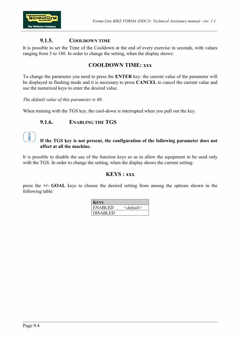
Forma Line BIKE FORMA (DDC5): Technical Assistance manual - rev. 1.1
Page 9.4
9.1.5. COOLDOWN TIME It is possible to set the Time of the Cooldown at the end of every exercise in seconds, with values ranging from 5 to 180. In order to change the setting, when the display shows:
COOLDOWN TIME: xxx To change the parameter you need to press the ENTER key: the current value of the parameter will be displayed in flashing mode and it is necessary to press CANCEL to cancel the current value and use the numerical keys to enter the desired value. The default value of this parameter is 60. When training with the TGS key, the cool-down is interrupted when you pull out the key.
9.1.6. ENABLING THE TGS
If the TGS key is not present, the configuration of the following parameter does not affect at all the machine.
It is possible to disable the use of the function keys so as to allow the equipment to be used only with the TGS. In order to change the setting, when the display shows the current setting:
KEYS : xxx press the +/- GOAL keys to choose the desired setting from among the options shown in the following table:
KEYS ENABLED <default> DISABLED
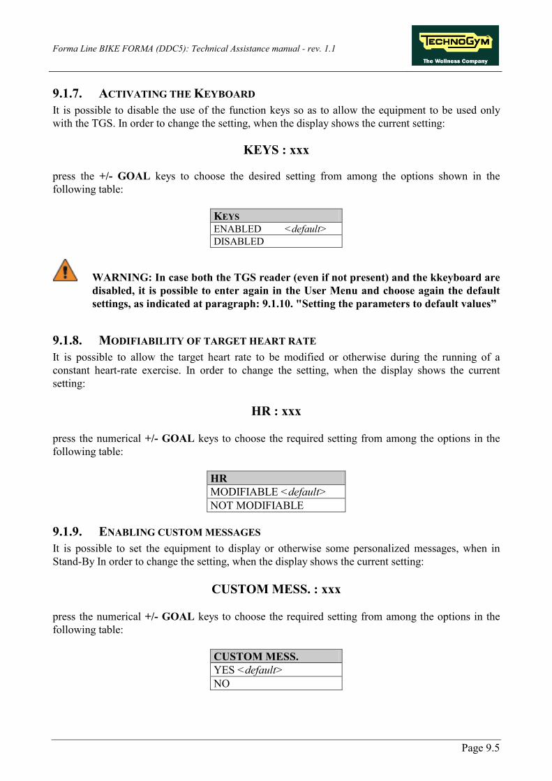
Forma Line BIKE FORMA (DDC5): Technical Assistance manual - rev. 1.1
Page 9.5
9.1.7. ACTIVATING THE KEYBOARD It is possible to disable the use of the function keys so as to allow the equipment to be used only with the TGS. In order to change the setting, when the display shows the current setting:
KEYS : xxx press the +/- GOAL keys to choose the desired setting from among the options shown in the following table:
KEYS ENABLED <default> DISABLED
WARNING: In case both the TGS reader (even if not present) and the kkeyboard are disabled, it is possible to enter again in the User Menu and choose again the default settings, as indicated at paragraph: 9.1.10. "Setting the parameters to default values”
9.1.8. MODIFIABILITY OF TARGET HEART RATE It is possible to allow the target heart rate to be modified or otherwise during the running of a constant heart-rate exercise. In order to change the setting, when the display shows the current setting:
HR : xxx press the numerical +/- GOAL keys to choose the required setting from among the options in the following table:
HR MODIFIABLE <default> NOT MODIFIABLE
9.1.9. ENABLING CUSTOM MESSAGES It is possible to set the equipment to display or otherwise some personalized messages, when in Stand-By In order to change the setting, when the display shows the current setting:
CUSTOM MESS. : xxx press the numerical +/- GOAL keys to choose the required setting from among the options in the following table:
CUSTOM MESS. YES <default> NO

Forma Line BIKE FORMA (DDC5): Technical Assistance manual - rev. 1.1
Page 9.6
9.1.10. SETTING THE PARAMETERS TO DEFAULT VALUES It is possible to set the default values of the user menu. In order to select the function, when the display shows:
DEFAULT CONFIG. Press ENTER to confirm the choice, + or - of the difficulty level to move onto the subsequent or previous parameter. If ENTER has been pressed, the display shows:
CONFIRM? confirm with ENTER or cancel by pressing CANCEL for a few seconds.
9.1.11. FORMATTING THE P&P KEY This function allows the formatting of a TGS key for the Plug-&-Play mode. In order to select the function, when the display shows:
FORMATTING P&P confirm with ENTER or cancel by pressing CANCEL for a few seconds. At the end of the configuration procedure press the CANCEL key for a few seconds to quit. The CANCEL key can be pressed at any time to interrupt the procedure and return to Stand-By.
9.1.12. SN This parameter allows the equipment serial number to be displayed. Press + or - of the difficulty level to move onto the subsequent parameter or the previous one.
SN:xxxx

Forma Line BIKE FORMA (DDC5): Technical Assistance manual - rev. 1.1
Page 9.7
9.2. CONFIGURATION OF THE TECHNICAL ASSISTANCE MENU
The configuration procedure for the equipment is activated when the equipment is in Stand-By. Press the 369 keys at the same time.
the Display will show:
ENTER PASSWORD: In order to access the procedure you need to enter the password 2501 which protects against unauthorised accesses and press the ENTER key in order to confirm. At this point two choices are offered:
1 = Tech Config , 2 = Troubleshooting Press the numerical key 1 to enter the technical parameter configuration menu and the equipment will start to display the current configuration structure as detailed later on.
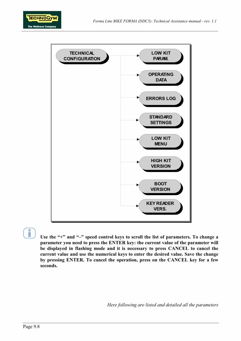
Forma Line BIKE FORMA (DDC5): Technical Assistance manual - rev. 1.1
Page 9.8
TECHNICAL CONFIGURATION
OPERATING DATA
LOW KIT MENU
LOW KIT PARAM.
HIGH KIT VERSION
STANDARD SETTINGS
ERRORS LOG
KEY READER VERS.
BOOTVERSION
Use the “+” and “–” speed control keys to scroll the list of parameters. To change a parameter you need to press the ENTER key: the current value of the parameter will be displayed in flashing mode and it is necessary to press CANCEL to cancel the current value and use the numerical keys to enter the desired value. Save the change by pressing ENTER. To cancel the operation, press on the CANCEL key for a few seconds.
Here following are listed and detailed all the parameters

Forma Line BIKE FORMA (DDC5): Technical Assistance manual - rev. 1.1
Page 9.9
9.2.1. LOW KIT PARAMETER This function allows you to access the parameters with which it is possible to change certain settings on the low kit. In order to access this menu, when the display shows:
LOW KIT PARAM. press ENTER. This function is structured in the following way:
LOW KIT PARAM.
Par.13
Par.01
WRITE TO LOW KIT ?
DEFAULT SETTINGS ?
READ FROM LOW KIT ?
.......................
Inside this function, in addition to the 13 configuration parameters, described below, we also find the following 3 sub-functions:
9.2.1.1. Read from low kit To recall the parameters memorized by the low kit and to be able to visualize them on the display, move using the +/- keys of the difficulty level until the display shows:
READ FROM LOW KIT ? press ENTER to load the parameters found in the low kit. Return to the upper level by pressing CANCEL for a few seconds.
9.2.1.2. Write to low kit To memorize on the low kit the values of the parameters currently on display, move using the +/- keys of the difficulty level until the display shows:
WRITE TO LOW KIT ? press ENTER to transfer the new data to the low kit. Return to the upper level by pressing CANCEL for a few seconds.

Forma Line BIKE FORMA (DDC5): Technical Assistance manual - rev. 1.1
Page 9.10
9.2.1.3. Default Setting To load the default values of the parameters, move using the +/- keys of the difficulty level until the display shows:
DEFAULT SETTING ?
press ENTER. The following will appear on the display:
CONFIRM?
press ENTER to recall the low kit default parameters. To return to the upper level press CANCEL for a few seconds.
To load these parameters on the low kit, use the “Write to low kit” function.
9.2.1.4. Table of Configuration parameters:
Id (Par.)
Unità misura Nome Descrizione Alim
1 decimali [Rt] Rapporto di trasmissione 135 2 [Rvel] Rapporto di velocità (parte intera) 9 3 mA [Im] Frenatura minima 500 4 W [Pmc] Potenza massima in continua 200 5 in centesimi [Km] Coefficiente correttivo della potenza 100 6 0.1N [Ca] Coppia di attrito utente 13 7 °C [Tea] Temperatura massima sulla bobina 125
8 Rpm. utente [RPMmin] Rpm minimi (rampa di taglio della frenatura) 30
9 tipo/sec [RpmF1] Scala d’integrazione degli rpm 1 10 rpm utente [RpmF2] Rpm soglia filtro 30 11 [Rvel] Rapporto di velocità (parte decimale) 0 12 0.1N [D_Ca] Delta Coppia attrito utente 8 13 - - Abilitazione registri con indirizzo ≥ 100 -

Forma Line BIKE FORMA (DDC5): Technical Assistance manual - rev. 1.1
Page 9.11
9.2.2. OPERATING DATA This function allows you to access the operating data of the equipment memorized on the low kit. In order to access this menu, when the display shows:
OPERATING DATA press ENTER. This function is structured in the following way:
OPERATING DATA
Life Kit H
Life Brake
WRITE TO LOW KIT ?
READ FROM LOW KIT ?
Life Kit L
Tot. Km
KJ
Inside this function, in addition to the equipment operating data, we also find 2 sub-functions, as described below:
9.2.2.1. Read from low kit To recall the parameters memorized by the low kit and to be able to visualize them on the display, move using the +/- keys of the difficulty level until the display shows:
READ FROM LOW KIT ? press ENTER to load the parameters found in the low kit. Return to the upper level by pressing CANCEL for a few seconds.

Forma Line BIKE FORMA (DDC5): Technical Assistance manual - rev. 1.1
Page 9.12
9.2.2.2. Write to low kit To memorize on the low kit the values of the parameters currently on display, move using the +/- keys of the difficulty level until the display shows:
WRITE TO LOW KIT ? press ENTER to transfer the new data to the low kit. Return to the upper level by pressing CANCEL for a few seconds.
9.2.2.3. Operating data The equipment operating data as displayed is updated every 10 minutes. This means that every time the equipment is switched off, the data which has been modified since the last saving to memory is lost.
Display Message Description Life Brake: Minutes x 10 of Brake operation
(measured by the Low Kit)
Life Kit High: Minutes x 10 of High Kit operation (measured by the High Kit)
Life Low Kit: Minutes x 10 of Low Kit operation (measured by the Low Kit)
KJ: total KJ spent (relating to all the exercises performed) (measured by the High Kit)
Tot Km: total Km travelled (relating to all the exercises performed) (measured by the Low Kit)
By selecting one of the items in the table above, it is possible to modify its content, but only by resetting its value. When you press ENTER the “Reset life…” message appears with the name of the selected item. If you press ENTER again, the value of the selected piece of information is reset, whereas if you press CANCEL you return to the previous value for the information.

Forma Line BIKE FORMA (DDC5): Technical Assistance manual - rev. 1.1
Page 9.13
9.2.3. ERRORS LOG This function allows you to access the log of errors generated by the equipment. In order to access this menu, when the display shows:
ERRORS LOG press ENTER. This function is structured in the following way:
ERRORS LOG
Error 10
Error 1
RESET ERRORS ?
READ FROM LOW KIT ?
.......................
COM.Fault
Inside this function, in addition to the errors recorded by the equipment, we also find 3 sub-functions, as described below:
9.2.3.1. Read from low kit To recall the errors memorized by the low kit and to be able to visualize them on the display, move using the +/- keys of the difficulty level until the display shows:
READ FROM LOW KIT ? press ENTER to load the parameters found in the low kit. Return to the upper level by pressing CANCEL for a few seconds.
9.2.3.2. Reset errors To reset the errors log on the high kit and on the low kit, move using the +/- keys of the difficulty level until the display shows:
RESET ERRORS ? press ENTER to reset the errors log. Return to the upper level by pressing CANCEL for a few seconds.

Forma Line BIKE FORMA (DDC5): Technical Assistance manual - rev. 1.1
Page 9.14
9.2.3.3. COM.Fault This is a counter which displays the number of serial communication errors between the high kit and the low kit. It increases every time a communication error is detected. Move using the +/- keys of the difficulty level until the display shows:
COM.FAULT X To reset the counter, press ENTER and the display will show:
RESET COM.FAULT? press ENTER to reset. Return to the upper level by pressing CANCEL for a few seconds.
9.2.3.4. Display errors The errors log provides a series of information as listed in the following table for every error generated by the equipment.
• Error Code, • Type of error, • Current at the time of the error • Distance in Km at the time of the error.
During movement, the Brake Board is capable of detecting possible faults. The possible detected errors are:
Error Code Description 1 OVERTEMPERATURE: this condition occurs when the temperature measured
by the board sensor exceeds 90°C.
8 OVERVOLTAGE: this condition occurs when the voltage +12Vdc exceeds 13.7Vdc (only on powered models).
You move on to the subsequent error by pressing the + key of the difficulty level. Otherwise the message containing the data of the current error is displayed again.

Forma Line BIKE FORMA (DDC5): Technical Assistance manual - rev. 1.1
Page 9.15
9.2.4. STANDARD SETTINGS This function allows you to reset the equipment operating data and at the same time to set the default values of the Brake Board parameters. In order to access this menu, when the display shows:
STANDARD SETTINGS ?
if you press ENTER, the following message will be displayed:
CONFIRM ?
By pressing ENTER again, all the default values will be re-instated. To return to the upper level press CANCEL for a few seconds.
9.2.5. LOW KIT MENU This function allows you to directly access Firmware (FW) of the Brake Board. In order to access this menu, when the display shows:
LOW KIT MENU
press ENTER. This function is structured as follows:

Forma Line BIKE FORMA (DDC5): Technical Assistance manual - rev. 1.1
Page 9.16
9.2.5.1. Low kit version This function allows you to display the version of the Firmware (FW) of the Brake Board. In order to access this menu, when the display shows:
LOW KIT VERSION
press ENTER and the SW numerical sequence will be displayed:
X.Y.Z Where:
• X = KERNEL • Y = Brake Board • Z = Brake Table
Which identifies the version of the Firmware (FW).
9.2.5.2. Config. registers This function allows to set on register at the time.
NOT used on FORLA LINE.
9.2.5.3. Low Kit fault code This function allows you to display any fault code which is blocking the low kit. In order to access this menu, when the display shows:
LOW KIT FAULT CODE if you press ENTER, the following message will be displayed:
FAULT=XX
If FAULT=00 is displayed, the Board is not at fault.
9.2.6. HIGH KIT VERSION This function allows you to display the version of the display SW. In order to display it, when the display shows:
HIGH KIT VERSION press ENTER and a message will be displayed which identifies the version of the SW.

Forma Line BIKE FORMA (DDC5): Technical Assistance manual - rev. 1.1
Page 9.17
9.2.7. BOOT VERSION This function allows you to display the BOOT version. In order to display it, when the display shows:
BOOT VERSION press ENTER and a message will be displayed which identifies the BOOT version.
The Boot Version parameter refers to the “boot” version relating to the display hardware. The boot is a part of the software which allows you to load the TG application onto the display board. The parameter is used solely as info. It is NOT possible to change the version or update it.
9.2.8. KEY READER VERSION
If the TGS key is not present, the configuration of the following parameter does not affect at all the machine.
This function allows you to display the Key Reader Version. In order to display it, when the display shows:
KEY READER VERSION
press ENTER and a message will be displayed which identifies the version of the KEY READER.

Forma Line BIKE FORMA (DDC5): Technical Assistance manual - rev. 1.1
Page 9.18
Page blank.

Forma Line BIKE FORMA (DDC5): Technical Assistance manual - rev. 1.1
Page 10.1
10. SCHEDULED MAINTENANCE To keep the machine in perfect working order and forestall possible problems, it is necessary to carry out the planned maintenance operations described below. These operations are essentially grouped according to the type of action and the technical skills needed perform them:
Refer to the SCHEDULED MAINTEANCE manual, that can be downloaded from TG DIRECT.
10.1. ROUTINE MAINTENANCE
ROUTINE maintenance operations can be carried out by the machine owner and do not require any special technical skills; they consist in simple external cleaning for the purposes of general hygiene.
WARNING: Refer to the USER manual.
ROUTINE MAINTENANCE: No special training.
10.2. SPECIAL MAINTENANCE
SPECIAL maintenance operations may only be carried out by a Qualified Technician specifically trained by Technogym and authorized to perform machine adjustment and start-up operations, repairs and maintenance, and checks on the functioning and wear of mechanical components, in order to ensure correct and safe operation of the machine.
WARNING: Refer to the TECHNICAL SERVICE manual.
SPECIAL MAINTENANCE: Qualified technician authorized by Technogym, and maintenance provided for in the Scheduled maintenance contract.


Forma Line BIKE FORMA (DDC5): Technical Assistance manual - rev. 1.1
Page 11.1
11. APPENDIX
11.1. TOOLS TO BE USED
The following tools are required to carry out all the fitting, adjustment and maintenance tasks on the equipment:
• Small Phillips screwdriver; • Medium-sized Phillips screwdriver; • Large Phillips screwdriver; • 7mm wrench; • 10mm wrench; • 13mm wrench; • 17mm wrench; • 19mm wrench; • 3mm Allen wrench; • 4mm Allen wrench; • 5mm Allen wrench; • 6mm Allen wrench; • 8mm Allen wrench; • Torque wrench; • Snap ring pincers;
Using the code R0003677AA, you can order a full set of Allen wrenches with the following sizes: 2, 2.5, 3, 4, 5, 6 and 8mm.


0SM00729AA-UK
TECHNOGYM S.p.A. Via G. Perticari, 20 - 47035 Gambettola (FC) – (Sede legale) Via Calcinaro, 2861 – 47522 Cesena (FC) – (Sede operativa)
ITALIA Tel.: +39-0547-650638 Fax: +39-0547-650150
e-mail: [email protected]