
Forma Direct Heat CO2 Incubator
86
Visit us online to register your warranty www.thermoscientific.com/labwarranty User Manual Forma Direct Heat CO2 Incubator Model 310 Series Operatign and Maintenance Manual 7010310 Rev. 16
Transcript of Forma Direct Heat CO2 Incubator

Visit us online to register your warrantywww.thermoscientific.com/labwarranty
User M
anual
Forma Direct Heat CO2 IncubatorModel 310 SeriesOperatign and Maintenance Manual 7010310 Rev. 16
Thermo ScientificThermo Scientific
Preface
Model 310 Series DH Incubator i
Preface
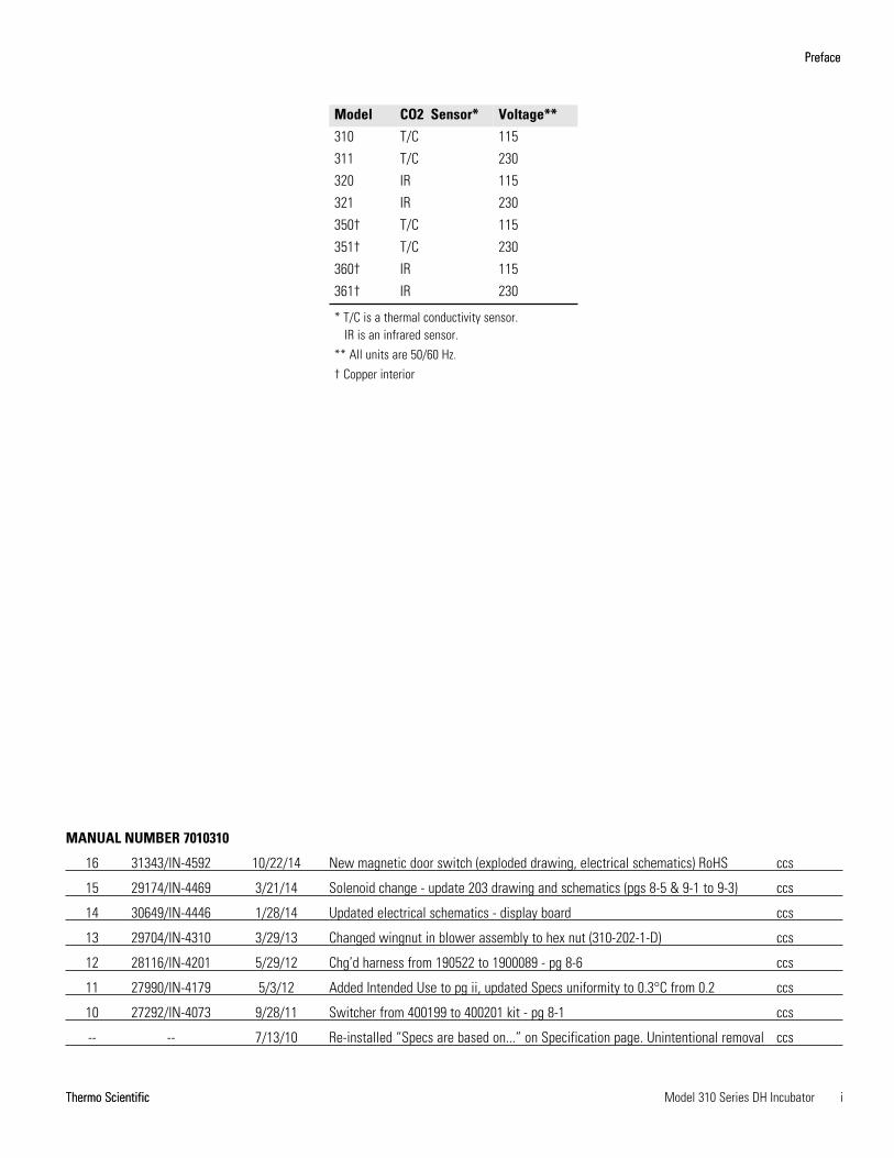
Model CO2 Sensor* Voltage**310 T/C 115
311 T/C 230
320 IR 115
321 IR 230
350† T/C 115
351† T/C 230
360† IR 115
361† IR 230
* T/C is a thermal conductivity sensor. IR is an infrared sensor.
** All units are 50/60 Hz.† Copper interior
MANUAL NUMBER 7010310
16 31343/IN-4592 10/22/14 New magnetic door switch (exploded drawing, electrical schematics) RoHS ccs
15 29174/IN-4469 3/21/14 Solenoid change - update 203 drawing and schematics (pgs 8-5 & 9-1 to 9-3) ccs
14 30649/IN-4446 1/28/14 Updated electrical schematics - display board ccs
13 29704/IN-4310 3/29/13 Changed wingnut in blower assembly to hex nut (310-202-1-D) ccs
12 28116/IN-4201 5/29/12 Chg’d harness from 190522 to 1900089 - pg 8-6 ccs
11 27990/IN-4179 5/3/12 Added Intended Use to pg ii, updated Specs uniformity to 0.3°C from 0.2 ccs
10 27292/IN-4073 9/28/11 Switcher from 400199 to 400201 kit - pg 8-1 ccs
-- -- 7/13/10 Re-installed “Specs are based on...” on Specification page. Unintentional removal ccs
Thermo Scientificii Model 310 Series DH Incubator
Preface
Contains Parts and Assemblies
Susceptible to Damage by
Electrostatic Discharge (ESD)
CAUTION
Important Read this instruction manual. Failure to read, understand and follow the instructions in this manualmay result in damage to the unit, injury to operating personnel, and poor equipment performance. s
Warning If this unit is not used in the manner specified in this operating manual, the protection provided bythe equipment design may be impaired. s
Intended Use: The 310 Series Direct Heat Incubators are designed to maintain an optimal environment forthe incubation of tissue and cell samples. These models are designed to maintain temperature and CarbonDioxide levels as set by the operator as well as monitoring chamber relative humidity. CO2 is controlled usingeither a thermo conductivity cell, or an infra-red sensor. T
The incubators are approved for general purpose use as a Microbiological Incubator (21 CFR 866.2540) andare also approved use in assisted reproductive procedures for the incubation of ova and embryos (21 CFR884.6120).
Non-intended Use: The 310 Series Direct Heat Incubators are not intended for use where electrical or physicalcontact with the patient is established.
These incubators are not intended to be operated in potentially explosive environments and are not intendedfor use with flammable materials.
Caution All internal adjustments and maintenance must be performed by qualified service personnel. s
Material in this manual is for information purposes only. The contents and the product it describes are subjectto change without notice. Thermo Fisher Scientific makes no representations or warranties with respect to thismanual. In no event shall Thermo be held liable for any damages, direct or incidental, arising out of or relatedto the use of this manual.
©2003 Thermo Fisher Scientific. All rights reserved.
Thermo Scientific Model 310 Series DH Incubator iii
Preface
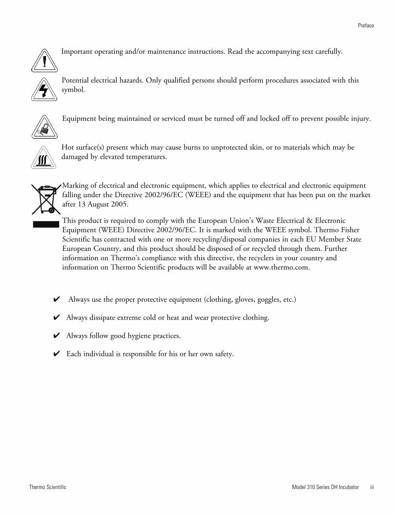
Important operating and/or maintenance instructions. Read the accompanying text carefully.
Potential electrical hazards. Only qualified persons should perform procedures associated with thissymbol.
Equipment being maintained or serviced must be turned off and locked off to prevent possible injury.
Hot surface(s) present which may cause burns to unprotected skin, or to materials which may bedamaged by elevated temperatures.
Marking of electrical and electronic equipment, which applies to electrical and electronic equipmentfalling under the Directive 2002/96/EC (WEEE) and the equipment that has been put on the marketafter 13 August 2005.
This product is required to comply with the European Union’s Waste Electrical & ElectronicEquipment (WEEE) Directive 2002/96/EC. It is marked with the WEEE symbol. Thermo FisherScientific has contracted with one or more recycling/disposal companies in each EU Member StateEuropean Country, and this product should be disposed of or recycled through them. Furtherinformation on Thermo’s compliance with this directive, the recyclers in your country andinformation on Thermo Scientific products will be available at www.thermo.com.
4 Always use the proper protective equipment (clothing, gloves, goggles, etc.)
4 Always dissipate extreme cold or heat and wear protective clothing.
4 Always follow good hygiene practices.
4 Each individual is responsible for his or her own safety.

Thermo Scientificiv Model 310 Series DH Incubator
Preface
Do You Need Information or Assistance on
Thermo Scientific Products?
If you do, please contact us 8:00 a.m. to 6:00 p.m. (Eastern Time) at:
1-740-373-4763 Direct
1-800-438-4851 Toll Free, U.S. and Canada
1-877-213-8051 FAX
http://www.thermoscientific.com Internet Worldwide Web Home Page
[email protected] Tech Support Email Address
Certified Service Web Page
Thermo Fisher Scientific
401 Millcreek Road, Box 649
Marietta, OH 45750
Our staff can provide information on pricing and give you quotations. We can
take your order and provide delivery information on major equipment items or make
arrangements to have your local sales representative contact you. Our products are listed on the
Internet and we can be contacted through our Internet home page.
Our staff can supply technical information about proper setup, operation or
troubleshooting of your equipment. We can fill your needs for spare or replacement parts or
provide you with on-site service. We can also provide you with a quotation on our Extended
Warranty for your Thermo Scientific products.
Whatever Thermo Scientific products you need or use, we will be happy to discuss your
applications. If you are experiencing technical problems, working together, we will help you
locate the problem and, chances are, correct it yourself...over the telephone without a service
call.
When more extensive service is necessary, we will assist you with direct factory trained
technicians or a qualified service organization for on-the-spot repair. If your service need is
covered by the warranty, we will arrange for the unit to be repaired at our expense and to your
satisfaction.
Regardless of your needs, our professional telephone technicians are available to assist you
Monday through Friday from 8:00 a.m. to 6:00 p.m. Eastern Time. Please contact us by
telephone or fax. If you wish to write, our mailing address is:
International customers, please contact your local Thermo Scientific distributor.
Sales Support
Service Support
www.unitylabservices.com
Thermo Scientific Model 310 Series DH Incubator vThermo Scientific
Preface
Warranty Notes
Information You Should Know Before Requesting Warranty Service
• Locate the model and serial numbers. A serial tag is located on the unit itself.
• For equipment service or maintenance, or with technical or special application inquiries, contact TechnicalServices at 1-800-438-4851 or 1-740-373-4763 (USA and Canada). Outside the USA, contact your local distributor.
Repairs NOT Covered Under Warranty
• Calibration of control parameters. Nominal calibrations are performed at the factory; typically ±1°C fortemperature, ±1% for gases, and ±5% for humidity. Our service personnel can provide precise calibrations asa billable service at your location. Calibration after a warranty repair is covered under the warranty.
• Damage resulting from use of improper quality water, chemicals or cleaning agents detrimental toequipment materials.
• Service calls for improper installation or operating instructions. Corrections to any of the following are billable services:
1) electrical service connection
2) tubing connections
3) gas regulators
4) gas tanks
5) unit leveling
6) room ventilation
7) adverse ambient temperature fluctuations
8) any repair external to the unit
• Damage resulting from accident, alteration, misuse, abuse, fire, flood, acts of God, or improperinstallation.
• Repairs to parts or systems resulting from unauthorized unit modifications.
• Any labor costs other than that specified during the parts and labor warranty period, which mayinclude additional warranty on CO2 sensors, blower motors, water jackets, etc.

Model 310 Series DH Incubator viThermo Scientific
Table of Contents
Installation and Start-Up . . . . . . . . . . . . . . . . . . . . . . . . . . . . . . . . . . . . . .1-1Control Panel Keys, Displays & Indicators . . . . . . . . . . . . . . . . . . . .1-2Keypad Operation . . . . . . . . . . . . . . . . . . . . . . . . . . . . . . . . . . . . . . .1-3Displays . . . . . . . . . . . . . . . . . . . . . . . . . . . . . . . . . . . . . . . . . . . . . . .1-4Installing the Incubator . . . . . . . . . . . . . . . . . . . . . . . . . . . . . . . . . . .1-4Incubator Start-Up . . . . . . . . . . . . . . . . . . . . . . . . . . . . . . . . . . . . . .1-11
Calibration . . . . . . . . . . . . . . . . . . . . . . . . . . . . . . . . . . . . . . . . . . . . . . . . . .2-1Calibrating the Temperature . . . . . . . . . . . . . . . . . . . . . . . . . . . . . . .2-1Calibrating the T/C CO2 System . . . . . . . . . . . . . . . . . . . . . . . . . . . .2-2Calibrating the Infrared CO2 System . . . . . . . . . . . . . . . . . . . . . . . . .2-3Calibrating Relative Humidity . . . . . . . . . . . . . . . . . . . . . . . . . . . . . .2-4
Configuration . . . . . . . . . . . . . . . . . . . . . . . . . . . . . . . . . . . . . . . . . . . . . . . .3-1Turn the Audible Alarm ON/OFF . . . . . . . . . . . . . . . . . . . . . . . . . .3-1Set an Access Code . . . . . . . . . . . . . . . . . . . . . . . . . . . . . . . . . . . . . . .3-1Set a Low Temp Alarm Limit . . . . . . . . . . . . . . . . . . . . . . . . . . . . . .3-2Enable the Low Temp Alarm to Trip Contacts . . . . . . . . . . . . . . . . .3-2Set a Low CO2 Alarm Limit . . . . . . . . . . . . . . . . . . . . . . . . . . . . . . . .3-3Setting a High CO2 Alarm Limit . . . . . . . . . . . . . . . . . . . . . . . . . . . .3-3Enable CO2 Alarms to Trip Contacts . . . . . . . . . . . . . . . . . . . . . . . .3-4Set New Zero Number for T/C CO2 Sensors . . . . . . . . . . . . . . . . . .3-4Set New Span Number for T/C CO2 Sensors . . . . . . . . . . . . . . . . . .3-5Set a Low RH Alarm Limit . . . . . . . . . . . . . . . . . . . . . . . . . . . . . . . .3-5Enable RH Alarms to Trip Contacts . . . . . . . . . . . . . . . . . . . . . . . . .3-6Enable Temp/RH to be Displayed . . . . . . . . . . . . . . . . . . . . . . . . . . .3-6Select Primary Tank w/ Gas Guard Option . . . . . . . . . . . . . . . . . . . .3-7Disable the Gas Guard System . . . . . . . . . . . . . . . . . . . . . . . . . . . . . .3-7Communications Address for RS485 . . . . . . . . . . . . . . . . . . . . . . . .3-8
Alarms . . . . . . . . . . . . . . . . . . . . . . . . . . . . . . . . . . . . . . . . . . . . . . . . . . . . . .4-1Temp Control Failure Alarm TMP CNTR ERR . . . . . . . . . . . . . . .4-2Sensor Fault Alarms . . . . . . . . . . . . . . . . . . . . . . . . . . . . . . . . . . . . . .4-2CO2 SNSR ERR . . . . . . . . . . . . . . . . . . . . . . . . . . . . . . . . . . . . . . . .4-2IR AUTOZ ERR . . . . . . . . . . . . . . . . . . . . . . . . . . . . . . . . . . . . . . . .4-2
Section 1
Section 2
Section 3
Section 4
vii Model 310 Series DH Incubator Thermo Scientific
Routine Maintenance . . . . . . . . . . . . . . . . . . . . . . . . . . . . . . . . . . . . . . . . .5-1Disinfecting the Incubator Interior . . . . . . . . . . . . . . . . . . . . . . . . . .5-1Cleaning the Cabinet Exterior . . . . . . . . . . . . . . . . . . . . . . . . . . . . . .5-2Cleaning the Glass Doors . . . . . . . . . . . . . . . . . . . . . . . . . . . . . . . . . .5-2Cleaning the Humidity Pan . . . . . . . . . . . . . . . . . . . . . . . . . . . . . . . .5-3Reversing the Door Swing . . . . . . . . . . . . . . . . . . . . . . . . . . . . . . . . .5-3HEPA Filter (Factory Installed Option) . . . . . . . . . . . . . . . . . . . . . . .5-8Replacing the Power Fuses . . . . . . . . . . . . . . . . . . . . . . . . . . . . . . . . .5-8Major Components . . . . . . . . . . . . . . . . . . . . . . . . . . . . . . . . . . . . . .5-9Electronics Section . . . . . . . . . . . . . . . . . . . . . . . . . . . . . . . . . . . . . . .5-9Replacing the Sample Air Filter . . . . . . . . . . . . . . . . . . . . . . . . . . . .5-10
Factory Options . . . . . . . . . . . . . . . . . . . . . . . . . . . . . . . . . . . . . . . . . . . . . .6-1Connect Remote Alarm Contacts . . . . . . . . . . . . . . . . . . . . . . . . . . .6-1Connect RS485 Interface . . . . . . . . . . . . . . . . . . . . . . . . . . . . . . . . .6-2Connecting the Analog Output Boards . . . . . . . . . . . . . . . . . . . . . . .6-2CO2 Gas Guard . . . . . . . . . . . . . . . . . . . . . . . . . . . . . . . . . . . . . . . . .6-5Humidity Readout . . . . . . . . . . . . . . . . . . . . . . . . . . . . . . . . . . . . . . .6-6Uninterruptible Power Supply Connections . . . . . . . . . . . . . . . . . . .6-7
Specifications . . . . . . . . . . . . . . . . . . . . . . . . . . . . . . . . . . . . . . . . . . . . . . .7-1
Spare Parts . . . . . . . . . . . . . . . . . . . . . . . . . . . . . . . . . . . . . . . . . . . . . . . . . .8-1
Electrical Schematics . . . . . . . . . . . . . . . . . . . . . . . . . . . . . . . . . . . . . . . .9-1
Warranty Information . . . . . . . . . . . . . . . . . . . . . . . . . . . . . . . . . . . . . . . .10-1
Table of Contents
Section 5
Section 6
Section 8
Section 7
Section 9
Section 10
Model 310 Series DH Incubator 1-1Thermo Scientific
Section 1 Installation and Start-Up
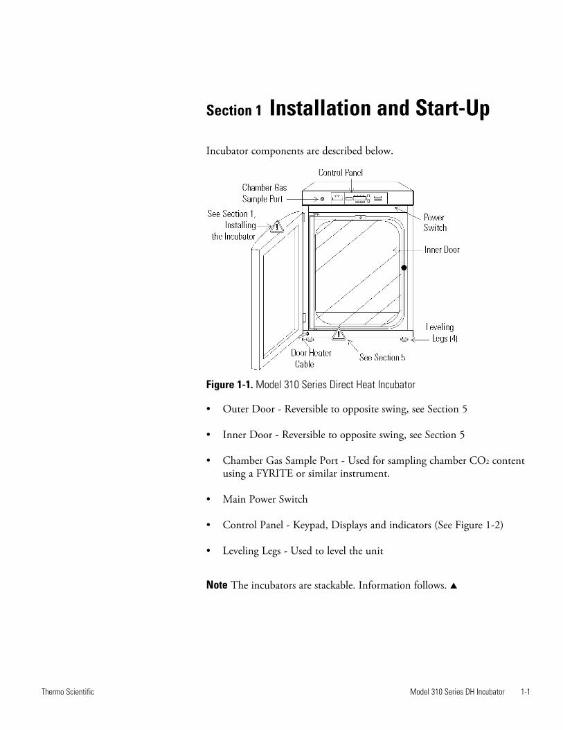
Incubator components are described below.
Figure 1-1. Model 310 Series Direct Heat Incubator
• Outer Door - Reversible to opposite swing, see Section 5
• Inner Door - Reversible to opposite swing, see Section 5
• Chamber Gas Sample Port - Used for sampling chamber CO2 contentusing a FYRITE or similar instrument.
• Main Power Switch
• Control Panel - Keypad, Displays and indicators (See Figure 1-2)
• Leveling Legs - Used to level the unit
Note The incubators are stackable. Information follows. s
1-2 Model 310 Series DH Incubator Thermo Scientific
Section 1Installation and Start-up
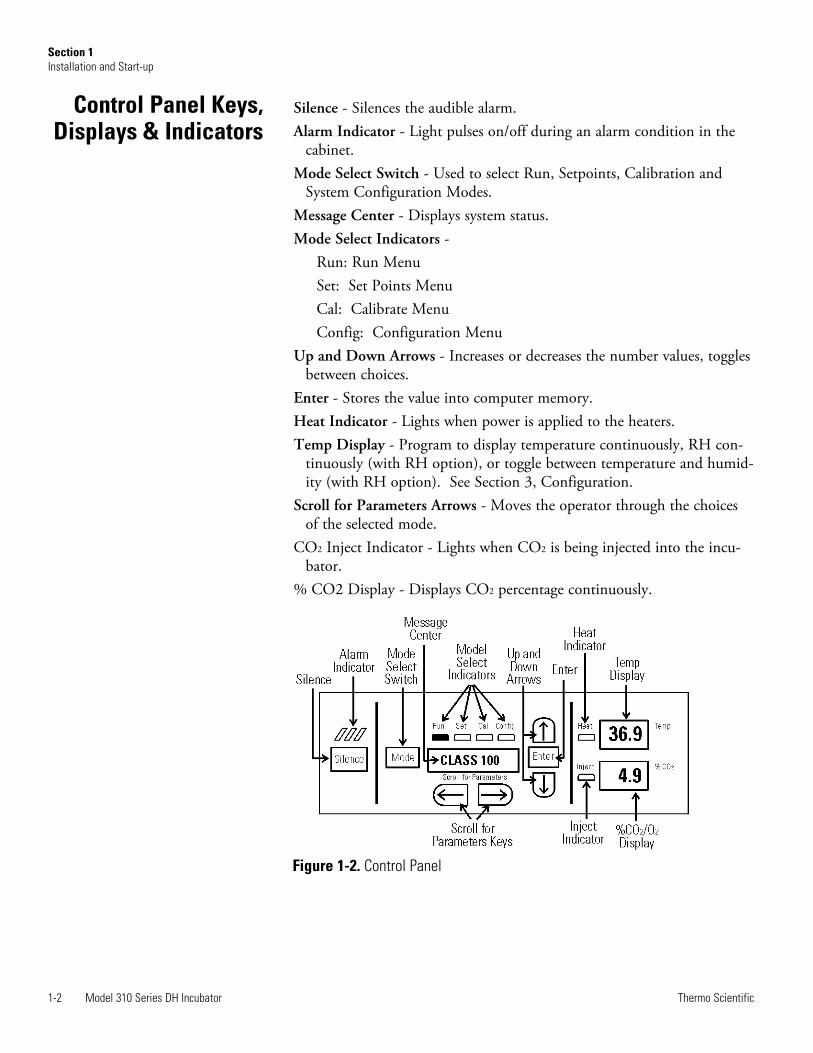
Silence - Silences the audible alarm. Alarm Indicator - Light pulses on/off during an alarm condition in the
cabinet. Mode Select Switch - Used to select Run, Setpoints, Calibration and
System Configuration Modes. Message Center - Displays system status. Mode Select Indicators -
Run: Run Menu Set: Set Points Menu Cal: Calibrate Menu Config: Configuration Menu
Up and Down Arrows - Increases or decreases the number values, togglesbetween choices.
Enter - Stores the value into computer memory.Heat Indicator - Lights when power is applied to the heaters.Temp Display - Program to display temperature continuously, RH con-
tinuously (with RH option), or toggle between temperature and humid-ity (with RH option). See Section 3, Configuration.
Scroll for Parameters Arrows - Moves the operator through the choicesof the selected mode.
CO2 Inject Indicator - Lights when CO2 is being injected into the incu-bator.
% CO2 Display - Displays CO2 percentage continuously.
Control Panel Keys,Displays & Indicators
Figure 1-2. Control Panel
Model 310 Series DH Incubator 1-3Thermo Scientific
Section 1Installation and Start-up
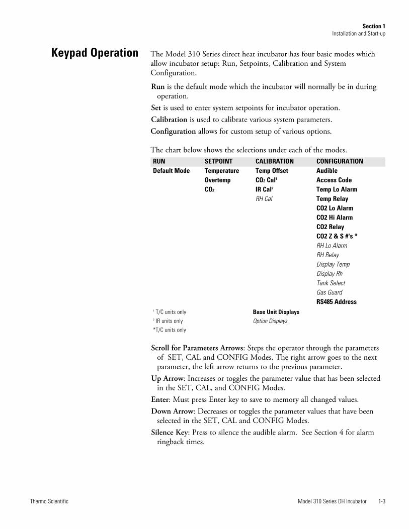
The Model 310 Series direct heat incubator has four basic modes whichallow incubator setup: Run, Setpoints, Calibration and SystemConfiguration.
Run is the default mode which the incubator will normally be in duringoperation.
Set is used to enter system setpoints for incubator operation. Calibration is used to calibrate various system parameters.Configuration allows for custom setup of various options.
The chart below shows the selections under each of the modes.
1 T/C units only Base Unit Displays2 IR units only Option Displays*T/C units only
Scroll for Parameters Arrows: Steps the operator through the parametersof SET, CAL and CONFIG Modes. The right arrow goes to the nextparameter, the left arrow returns to the previous parameter.
Up Arrow: Increases or toggles the parameter value that has been selectedin the SET, CAL, and CONFIG Modes.
Enter: Must press Enter key to save to memory all changed values.Down Arrow: Decreases or toggles the parameter values that have been
selected in the SET, CAL and CONFIG Modes.Silence Key: Press to silence the audible alarm. See Section 4 for alarm
ringback times.
Keypad Operation
RUN SETPOINT CALIBRATION CONFIGURATIONDefault Mode Temperature Temp Offset Audible
Overtemp CO2 Cal1 Access CodeCO2 IR Cal2 Temp Lo Alarm
RH Cal Temp RelayCO2 Lo AlarmCO2 Hi AlarmCO2 RelayCO2 Z & S #'s *RH Lo AlarmRH RelayDisplay TempDisplay RhTank SelectGas GuardRS485 Address
Message Center: Displays the system status (Mode) at all times. DisplaysSYSTEM OK during normal operation, or alarm messages if the systemdetects an alarm condition. See Section 4, Alarms.
Upper and Lower Displays: These 7 segment displays vary dependingupon the options present and the configuration chosen. The upper dis-play can display temp or RH, or toggle between them. The bottom dis-play shows CO2 continuously.
Warning Single and stacked units must be installed against a wall orsimilar structure. Maintain a three-inch clearance behind the incubator forelectrical and gas hook-ups. s
1. Locate the unit on a firm level surface capable of supporting the unit’sweight of 205 lbs.
2. Locate the unit away from doors and windows and heating and airconditioning ducts.
3. Lift the unit only by the sides of the cabinet base . Do not attempt tolift it by the front and back . This places stress on the outer doorhinges.
Caution When stacking incubators, the direct heat incubator must be thetop unit. Never stack a water-jacketed incubator on top of a Model 310Series unit. s
Warning With incubators in a stacked configuration, do not leave bothexterior doors open at the same time. s
Warning If the units have been in operation, shut them both off anddisconnect from the power source before beginning any service work. s
Note Two stacking brackets (shown at right) are includedin the parts bag shipped with each incubator. s
1-4 Model 310 Series DH Incubator Thermo Scientific
Section 1Installation and Start-Up
Displays
Installing theIncubator
Stacking the Incubators
Figure 1-3.Stacking Brackets

1. Remove and discard the slotted headscrews on the top of the bottom incubator(Figure 1-4). Replace with 5/16 HH boltsand flatwashers included in the stackingkit. Do not tighten.
2. Remove the kickplate from below the door on the top incubator(Figure 1-5). Two Phillips screws secure the plate. Note the notches atthe base of the incubator frame.
3. Disconnect the door cable from the connector behind the plate. Liftthe door off the hinge pins and set it aside. The hinge pins are notattached to the brackets and may fall out when the door is lifted off.
4. Unscrew and remove the leveling feet from the top unit and lift it ontothe bottom unit, offsetting the base of the top unit approximately 2-3inches behind the screws identified by the arrows in Figure 1-4.
Warning This incubator weighs 205 lbs. Have sufficient personnelavailable when lifting. Lift the unit only by the sides of the cabinet base.Do not attempt to lift it by the front and back as this places stress on theouter door hinge. s
5. Align the sides of the top unit with the bottom unit and slide the topunit forward until the notches in the base of the top unit align withthe bolts in the top of the bottom unit. The flatwashers should slideover the base frame. Tighten bolts.
6. Remove the four nylon plugs on the lower back of the upper incubator.
7. Insert the stacking brackets into the slots on the back of the controlpanel of the bottom unit as shown in Figure 1-6.
Model 310 Series DH Incubator 1-5Thermo Scientific
Section 1Installation and Start-Up
Stacking (continued)
Figure 1-4. Slotted Head Screws Figure 1-5. Align
Figure 1-6. Brackets Installed

8. Align the slots in the brackets with the mounting holes on the back ofthe top incubator. Secure the brackets with the screws provided in thestacking kit.
9. Make sure the hinge pins are in the hinge brackets. Slide the door ontothe hinge pins.
10. Secure the door heater cable to the connector below the door andreplace the kick plate on the top unit, taking care not to crimp cable.
11. The stacked incubators are ready for service.
Remove vinyl from shelf channels, duct sheets, and air duct, if present.Using a suitable laboratory disinfectant, disinfect all interior surfacesincluding shelves and shelf supports, door gaskets, blower wheel and CO2
sensor. Refer to Section 5.
Caution Before using any cleaning or decontamination method exceptthose recommended by the manufacturer, users should check with themanufacturer that the proposed method will not damage the equipment.Accidental spills of hazardous materials on or inside this unit are theresponsibility of the user. s
1. Install the large sheet metal shelf supports with the tabs facing into thecenter of the chamber with their slots up. There are no right side orleft side supports. Simply turn one of them to fit the opposite side. Tiltthe shelf supports as they are placed in the chamber so the tops fit intothe top air duct, then guide them into the vertical position. Figure 1-7shows the support as it would be oriented for right side of chamber.
1-6 Model 310 Series DH Incubator Thermo Scientific
Section 1Installation and Start-Up
Preliminary Cleaning andDisinfecting
Installing the Shelves
Figure 1-7. Shelf Channels and Ductwork
Stacking (continued)
2. Note there is no difference in the left side and right side shelf channels.
3. Install the shelf channels by placing the channel’s rear slot over theappropriate rear tab on the shelf support. Pull the shelf channelforward and engage the channel’s front slot into the shelf support’sappropriate forward tab. Refer to Figure 1-8.
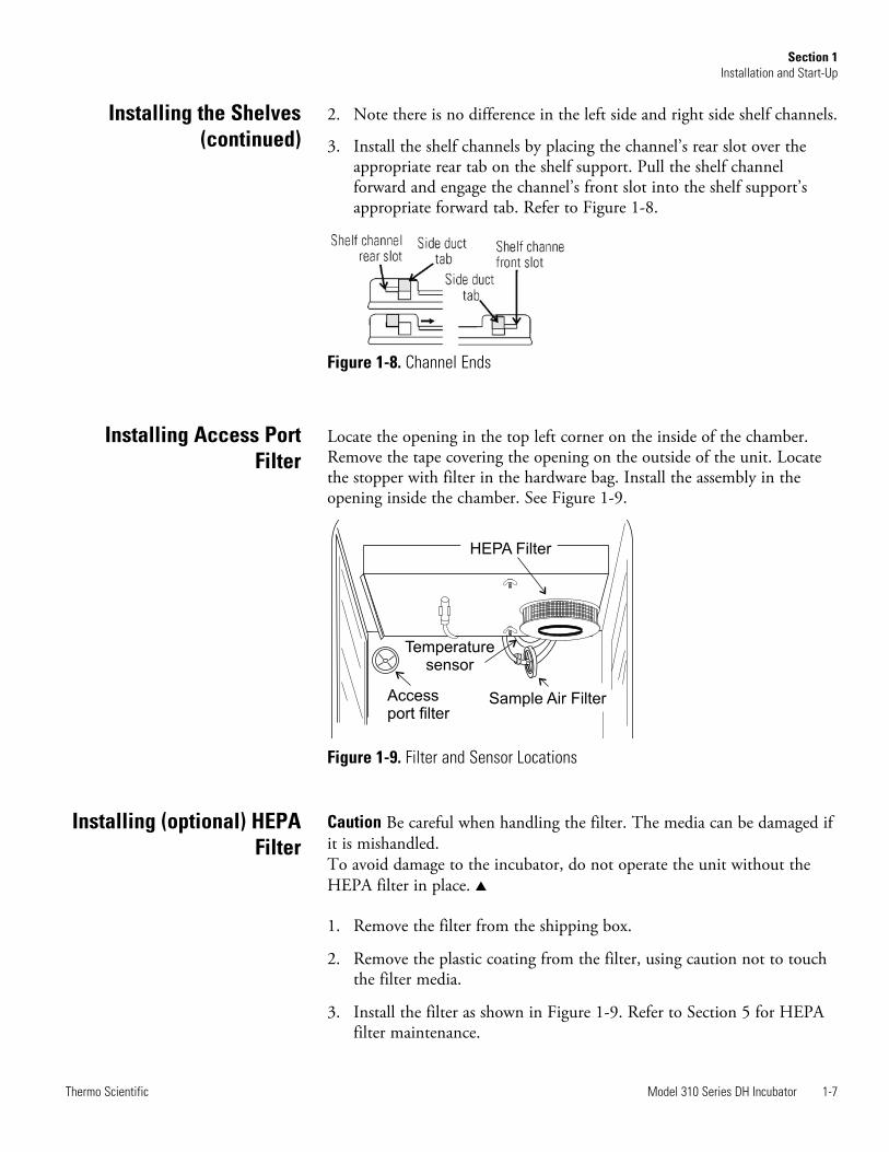
Locate the opening in the top left corner on the inside of the chamber.Remove the tape covering the opening on the outside of the unit. Locatethe stopper with filter in the hardware bag. Install the assembly in theopening inside the chamber. See Figure 1-9.
Figure 1-9. Filter and Sensor Locations
Caution Be careful when handling the filter. The media can be damaged ifit is mishandled. To avoid damage to the incubator, do not operate the unit without theHEPA filter in place. s
1. Remove the filter from the shipping box.
2. Remove the plastic coating from the filter, using caution not to touchthe filter media.
3. Install the filter as shown in Figure 1-9. Refer to Section 5 for HEPAfilter maintenance.
Model 310 Series DH Incubator 1-7Thermo Scientific
Section 1Installation and Start-Up
Figure 1-8. Channel Ends
HEPA Filter
Sample Air Filter
Temperature
sensor
Access
port filter
Installing (optional) HEPAFilter
Installing Access PortFilter
Installing the Shelves(continued)
Leveling the Unit
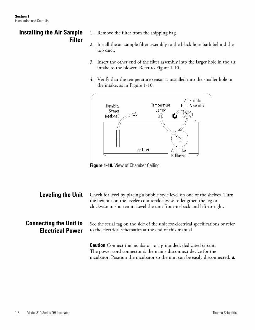
1. Remove the filter from the shipping bag.
2. Install the air sample filter assembly to the black hose barb behind thetop duct.
3. Insert the other end of the filter assembly into the larger hole in the airintake to the blower. Refer to Figure 1-10.
4. Verify that the temperature sensor is installed into the smaller hole inthe intake, as in Figure 1-10.
Check for level by placing a bubble style level on one of the shelves. Turnthe hex nut on the leveler counterclockwise to lengthen the leg orclockwise to shorten it. Level the unit front-to-back and left-to-right.
See the serial tag on the side of the unit for electrical specifications or referto the electrical schematics at the end of this manual.
Caution Connect the incubator to a grounded, dedicated circuit. The power cord connector is the mains disconnect device for theincubator. Position the incubator so the unit can be easily disconnected. s
1-8 Model 310 Series DH Incubator Thermo Scientific
Section 1Installation and Start-Up
Figure 1-10. View of Chamber Ceiling
Installing the Air SampleFilter
Connecting the Unit toElectrical Power
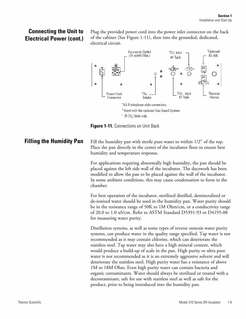
Plug the provided power cord into the power inlet connector on the backof the cabinet (See Figure 1-11), then into the grounded, dedicated,electrical circuit.
Figure 1-11. Connections on Unit Back
Fill the humidity pan with sterile pure water to within 1/2” of the top.Place the pan directly in the center of the incubator floor to ensure besthumidity and temperature response.
For applications requiring abnormally high humidity, the pan should beplaced against the left side wall of the incubator. The ductwork has beenmodified to allow the pan to be placed against the wall of the incubator.In some ambient conditions, this may cause condensation to form in thechamber.
For best operation of the incubator, sterilized distilled, demineralized orde-ionized water should be used in the humidity pan. Water purity shouldbe in the resistance range of 50K to 1M Ohm/cm, or a conductivity rangeof 20.0 to 1.0 uS/cm. Refer to ASTM Standard D5391-93 or D4195-88for measuring water purity.
Distillation systems, as well as some types of reverse osmosis water puritysystems, can produce water in the quality range specified. Tap water is notrecommended as it may contain chlorine, which can deteriorate thestainless steel. Tap water may also have a high mineral content, whichwould produce a build-up of scale in the pan. High purity or ultra purewater is not recommended as it is an extremely aggressive solvent and willdeteriorate the stainless steel. High purity water has a resistance of above1M to 18M Ohm. Even high purity water can contain bacteria andorganic contaminants. Water should always be sterilized or treated with adecontaminant, safe for use with stainless steel as well as safe for theproduct, prior to being introduced into the humidity pan.
Model 310 Series DH Incubator 1-9Thermo Scientific
Section 1Installation and Start-Up
Filling the Humidity Pan
Connecting the Unit toElectrical Power (cont.)

Caution Distilled or de-ionized water used in the humidity pan must bewithin a water quality resistance range of 50K to 1M Ohm/cm to protectand prolong the life of the stainless steel. Use of chlorinated water, ordecontamination products containing chlorine, will deteriorate the stainlesssteel and cause rust, voiding the warranty. s
Check the level and change the water frequently to avoid contamination.Do not allow the water level to fluctuate significantly. “Dry-outs” will havean adverse effect on the humidity level and CO2 calibration of the T/Cunits.
Warning High concentrations of CO2 gas can cause asphyxiation! OSHAStandards specify that employee exposure to carbon dioxide in any eight-hour shift of a 40-hour work week shall not exceed the eight-hour timeweighted average of 5000 PPM (0.5% CO2). The short term exposurelimit for 15 minutes or less is 30,000 ppm (3% CO2). Carbon dioxidemonitors are recommended for confined areas where concentrations ofcarbon dioxide gas can accumulate. s
Warning This incubator is designed to be operated with CO2 gas only.Connecting a flammable or toxic gas can result in a hazardous condition.Gases other than CO2 should not be connected to this equipment. CO2
gas cylinders have a UN1013 label on the cylinder and are equipped with aCGA 320 outlet valve. Check the gas cylinder for the proper identificationlabels. The CO2 gas supply being connected to the incubator should beindustrial grade, 99.5% pure. Do not use CO2 gas cylinders equipped withsiphon tubes. A siphon tube is used to extract liquid CO2 from thecylinder which can damage the pressure regulator. Consult with your gassupplier to ensure that the CO2 cylinder does not contain a siphon tube.Gas cylinders should also be secured to a wall or other stationary object toprevent them from tipping.A two-stage CO2 pressure regulator is required to be installed on the outletvalve of the gas cylinder. Input pressure to the incubator must bemaintained at 15 psig (103.4 kPa), ±5 psig, for proper performance of theCO2 control system. A single stage CO2 pressure regulator will notmaintain 15 psig (103.4 kPa) to the incubator as the pressure in the CO2
cylinder decreases; therefore, a two stage regulator is recommended.If higher purity CO2 is desired inside the incubator (greater than 99.5%pure), the pressure regulator should be constructed with a stainless steeldiaphragm, along with specifying the purity of the CO2 from the gassupplier. Follow the manufacturer’s instructions to ensure proper and safeinstallation of the pressure regulator on the gas cylinder.Consult your facility safety officer to ensure that the equipment is installedin accordance with the codes and regulations applicable in your area. s
1-10 Model 310 Series DH Incubator Thermo Scientific
Section 1Installation and Start-Up
Connecting the CO2 GasSupply
Filling the Humidity Pan(cont.)
The CO2 gas supply being connected should be industrial grade 99.5%pure and should not contain siphon tubes. Install a two-stage pressureregulator at the cylinder outlet. The high pressure gauge at the tank shouldhave 0-2000 psig range. The low pressure gauge, at the incubator inlet,should have a 0-30 psig range. Input pressure to the incubator must bemaintained at 15 psig (103.4 kPa).
The incubator has serrated fittings on the back of the cabinet to connectthe gas supply. Refer to Figure 1-11. The fitting is labeled CO2 Inlet #1Tank. Make sure that the connections are secured with clamps. Check allfittings for leaks.
For units having the CO2 Gas Guard option, refer to Section 6.
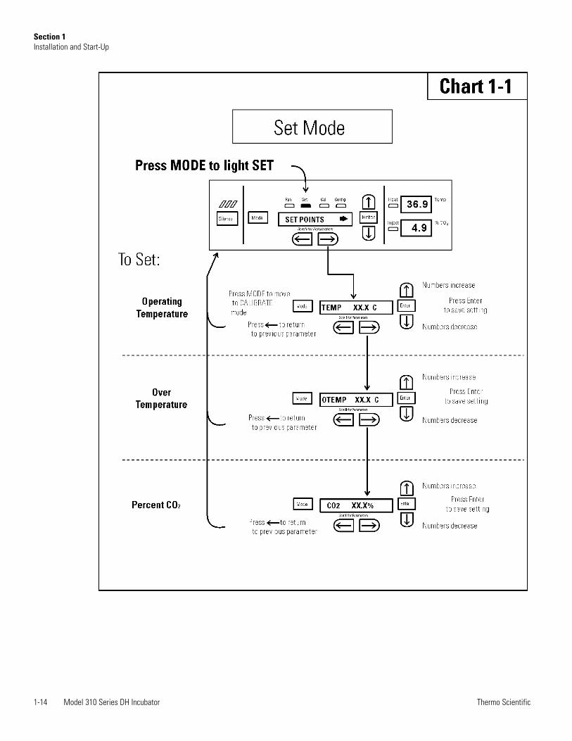
With the incubator properly installed and connected to power, thehumidity pan filled, and the unit connected to gas supplies, systemsetpoints can be entered. The following setpoints can be entered in Setmode: Temperature, Overtemperature and CO2. To enter Set mode, pressthe Mode key until the Set indicator lights. Press the right and/or leftarrow keys until the proper parameter appears in the message center. SeeChart 1-1 for more detail.
Model 310 Series incubators have an operating temperature range of 10°Cto 50°C, depending on ambient temperature. The incubator is shippedfrom the factory with a temperature setpoint of 10°C. At this setting, allheaters are turned off. To change the operating temperature setpoint:
1. Press the Mode key until the Set indicator lights.
2. Press the right arrow until “Temp XX.X” is displayed in the messagecenter.
3. Press the up/down arrow key until the desired temperature setpoint isdisplayed.
4. Press Enter to save the setpoint.
5. Press the Mode key until the Run indicator lights for Run mode orpress the right/left arrow keys to go to next/previous parameter.
Model 310 Series DH Incubator 1-11Thermo Scientific
Section 1Installation and Start-Up
Incubator Start-Up
Setting the OperatingTemperature
Connecting the CO2 gasSupply (continued)
Caution The independent overtemp system is designed as a safety toprotect the incubator only. It is not intended to protect or limit themaximum temperature of the cell cultures or customer’s equipment insidethe incubator if an overtemp condition occurs. s
Model 310 Series incubators are equipped with a secondary temperaturemonitoring system to monitor the air temperature inside the cabinet. Thissystem is designed as a safety device to turn off all heaters in the event of atemperature control failure. Temperature control in the incubator will be ±1° of the overtemp setpoint.
The factory overtemperature setpoint (default) is 40°C. However, theovertemp can be set up to 55°C in 0.5° increments.
If the incubator’s operating temperature setpoint is set above the overtempsetpoint, the overtemp setpoint will automatically update to 1°C above thetemperature setpoint. It is recommended that the overtemp setpoint bemaintained at 1°C over the operating temperature setpoint.
To set the Overtemp setpoint:
1. Press the Mode key until the Set indicator lights
2. Press the right arrow until Otemp XX.X is displayed in the messagecenter
3. Press the up or down arrow key until the desired Overtemp setpoint isdisplayed
4. Press Enter to save the setting
5. Press the Mode key until the Run indicator lights or press the right orleft arrow to go to the next or previous parameter.
1-12 Model 310 Series DH Incubator Thermo Scientific
Section 1Installation and Start-Up
Setting the OvertempSetpoint
All T/C CO2 cells are calibrated at the factory at 37°C, high humidity, and10% CO2. Therefore, if a temperature setpoint of 37°C has been entered,the humidity pan has been filled and the CO2 control is to run between 0-10% with a T/C CO2 sensor, the CO2 setpoint may be enteredimmediately. Otherwise, it is important to allow the unit 12 hours tostabilize at the temperature setpoint before entering the CO2 setpoint.
All models of the incubator have a CO2 setpoint range of 0.0% to 20.0%.The incubator is shipped from the factory with a CO2 setpoint of 0.0%.At this setting, all CO2 control and alarms are turned off. To change theCO2 setpoint:
1. Press the Mode key until the Set indicator lights.
2. Press the right arrow until “CO2 XX.X” is displayed in the messagecenter.
3. Press the up/down arrows until the desired CO2 setpoint is displayed.
4. Press Enter to save the setpoint.
5. Press the Mode key until the Run indicator lights to go to Run modeor press the right/left arrow keys to go to next/previous parameter.
Model 310 Series DH Incubator 1-13Thermo Scientific
Section 1Installation and Start-Up
Setting the CO2 Setpoint
1-14 Model 310 Series DH Incubator Thermo Scientific
Section 1Installation and Start-Up
Model 310 Series DH Incubator 2-1Thermo Scientific
Section 2 Calibration
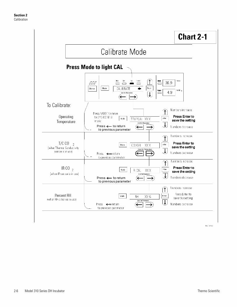
After the unit has stabilized, several different systems can be calibrated. Inthe calibration mode, the air temperature, CO2 and RH levels can becalibrated to reference instruments. To access the calibration mode, pressthe Mode key until the Cal indicator lights. Press the right and/or leftarrow until the proper parameter appears in the message center. See Chart2-1 at the end of this section for more detail.
Calibration frequency is dependent on use, ambient conditions andaccuracy required. A good laboratory practice would require at least anannual calibration check. On new installations, all parameters should bechecked after the stabilization period.
Prior to calibration, the user should be aware of the following systemfunctions. While the unit is in the calibration mode, all system controlfunctions are stopped so the unit remains stable. Readout of the systembeing calibrated will appear on the message center. If no keys are pressedfor approximately five minutes while in calibration mode, the system willreset to Run mode so control functions are reactivated.
Caution Before making any calibration or adjustments to the unit, it isimperative that all reference instruments be properly calibrated. s
Before calibration, allow the cabinet temperature to stabilize. Place thecalibrated instrument in the center of the chamber. The instrumentshould be in the airflow, not against the shelf.
Temperature Stabilization Periods
Startup - Allow 12 hours for the temperature in the cabinet to stabilizebefore proceeding.
Already Operating - Allow at least 2 hours after the display reachessetpoint for temperature to stabilize before proceeding.
Calibrating theTemperature
2-2 Model 310 Series DH Incubator Thermo Scientific
Section 2Calibration
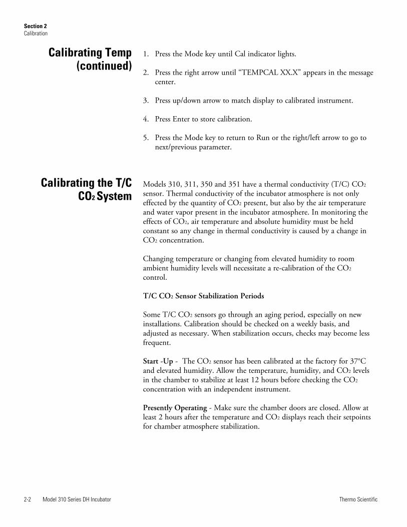
1. Press the Mode key until Cal indicator lights.
2. Press the right arrow until “TEMPCAL XX.X” appears in the messagecenter.
3. Press up/down arrow to match display to calibrated instrument.
4. Press Enter to store calibration.
5. Press the Mode key to return to Run or the right/left arrow to go tonext/previous parameter.
Models 310, 311, 350 and 351 have a thermal conductivity (T/C) CO2
sensor. Thermal conductivity of the incubator atmosphere is not onlyeffected by the quantity of CO2 present, but also by the air temperatureand water vapor present in the incubator atmosphere. In monitoring theeffects of CO2, air temperature and absolute humidity must be heldconstant so any change in thermal conductivity is caused by a change inCO2 concentration.
Changing temperature or changing from elevated humidity to roomambient humidity levels will necessitate a re-calibration of the CO2
control.
T/C CO2 Sensor Stabilization Periods
Some T/C CO2 sensors go through an aging period, especially on newinstallations. Calibration should be checked on a weekly basis, andadjusted as necessary. When stabilization occurs, checks may become lessfrequent.
Start -Up - The CO2 sensor has been calibrated at the factory for 37°Cand elevated humidity. Allow the temperature, humidity, and CO2 levelsin the chamber to stabilize at least 12 hours before checking the CO2
concentration with an independent instrument.
Presently Operating - Make sure the chamber doors are closed. Allow atleast 2 hours after the temperature and CO2 displays reach their setpointsfor chamber atmosphere stabilization.
Calibrating the T/CCO2 System
Calibrating Temp(continued)
Model 310 Series DH Incubator 2-3Thermo Scientific
Section 2Calibration
1. Make sure the stabilization periods outlined above are followed.
2. Sample the chamber atmosphere through the sample port with anindependent instrument. Sample the atmosphere at least 3 times toensure accuracy of the instrument.
3. Press the Mode key until the Cal indicator lights.
4. Press the right arrow until “CO2 CAL XX.X” is displayed in themessage center.
5. Press the up /down arrows to change the display to match theindependent instrument.
6. Press Enter to store the calibration.
7. Press the Mode key to return to Run or the right or left arrows to goto the next/ previous parameter.
Models 320, 321, 360 and 361 have an infrared (IR) CO2 sensor. InfraredCO2 sensors are not effected by chamber atmosphere temperature orhumidity. However, the light detector in the sensor is effected by widetemperature changes. Therefore, changing temperature setpoints couldnecessitate a recalibration of the CO2. Chamber temperature should beallowed to stabilize before checking CO2 concentrations with anindependent instrument, especially on start-up.
All models equipped with an IR/CO2 sensor have an automatic calibrationwhich occurs every 24 hours and lasts for 5 to 6 minutes. Duringautomatic calibration, the CO2 display is blanked out and HEPA filteredroom air is pumped through the CO2 sensor. A new CO2 calibration valueis stored in memory for use as the 0.0% CO2 reference point. The keypad/control panel is locked during calibration, with the message center reading“CO2 AUTO CAL”.
IR CO2 Sensor Stabilization Times
Start-Up- Allow the temperature and the CO2 of the cabinet to stabilize atleast 12 hours before proceeding.
Presently Operating - Allow CO2 to stabilize at least 2 hours at setpointbefore proceeding.
Calibrating theInfrared CO2 System
Calibrating T/C CO2
System (continued)
Calibrating RelativeHumidity
1. Measure the CO2 concentration in the chamber through the gassample port with a FYRITE or other independent instrument. Severalreadings should be taken to ensure accuracy.
2. Press the Mode key until the Cal indicator lights.
3. Press the right arrow until “IR CAL XX.X” appears in the messagecenter.
4. Press the up/down arrow to adjust the display to match theindependent instrument reading.
5. Press Enter to store the calibration.
6. After Enter is pressed, the unit will go into a calibration cycle that willlast 5 to 6 minutes. The control panel is locked during this cycle.
7. Press the Mode key to return to Run mode.
All 310 Series incubators can be equipped with an optional direct readoutrelative humidity (RH) sensor. This is a readout only of the chamberrelative humidity level. It does not provide any control of the relativehumidity in the cabinet.
Relative Humidity Stabilization Times
Start-Up - Allow 12 hours for the relative humidity and temperature in thechamber to stabilize before proceeding.
Already Operating - Allow at least 2 hours after temperature displayreaches setpoint for relative humidity to stabilize before proceeding.
2-4 Model 310 Series DH Incubator Thermo Scientific
Section 2Calibration
Calibrating the IR CO2
System (continued)
1. Place an accurate independent instrument in the center of thechamber. Allow at least 30 minutes for RH to stabilize.
2. Press the Mode key until the Cal indicator lights.
3. Press the right arrow key until “RH CAL XX” appears in the messagecenter.
4. Press the up/down arrow to match the display to the independentinstrument.
5. Press Enter to store the calibration.
6. Press the Mode key to return to Run mode.
If a reliable RH measuring device is not available, the display may becalibrated to a typical level.
1. Follow the RH stabilization periods outlined previously.
2. With a full humidity pan and stable temperature, the relative humidityin the chamber will be 95%.
3. Using Step 3-5 of the relative humidity sensor adjustment, adjust thedisplay to 95%.
This calibration method should be accurate to within 5%.
Model 310 Series DH Incubator 2-5Thermo Scientific
Section 2Calibration
Calibrating RelativeHumidity (continued)
2-6 Model 310 Series DH Incubator Thermo Scientific
Section 2Calibration
Model 310 Series DH Incubator 3-1Thermo Scientific
Section 3 Configuration
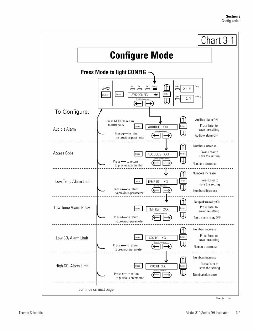
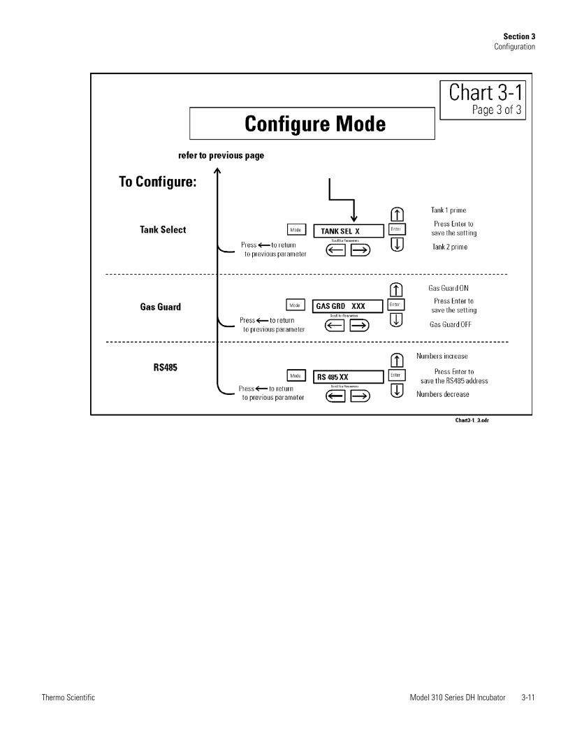
Several features available in Configuration Mode allow custom setup of theincubator. These features are listed and described below. All features maynot be necessary in all applications, but are available if needed. To enterConfiguration mode, press the Mode key until the Config indicator lights.Press the right and/or left arrow until the appropriate parameter appears inthe message center. See Chart 3-1 for more detail.
The audible alarm can be turned on or off. The factory setting is ON.
1. Press the Mode key until the Config indicator lights.
2. Press the right arrow until Audible XXX is displayed in the messagecenter.
3. Press up/down arrow to toggle Audible ON/OFF.
4. Press Enter to save the setting.
5. Press the Mode key to return to run mode or right/left to go tonext/previous parameter.
A 3-digit Access Code can be entered to avoid unauthorized personnelfrom changing the setpoints, calibration, or configuration. A setting of000 will bypass the access code. The factory setting is 000.
1. Press the Mode key until the Config indicator lights.
2. Press the right arrow until Acc Code XXX is displayed in the messagecenter.
3. Press up/down arrow to change the access code.
4. Press Enter to save the access code.
5. Press the Mode key to return to the Run mode or right/left to go tonext/previous parameter.
Set an Access Code
Turn the AudibleAlarm ON/OFF
Enable the Low TempAlarm to Trip Contacts
3-2 Model 310 Series DH Incubator Thermo Scientific
Section 3Configuration
Set a Low TempAlarm Limit
The low temp alarm limit (tracking alarm) is the deviation from thetemperature setpoint which will cause a low temp alarm. The low tempalarm is variable from 0.5° below setpoint to 5° below setpoint. Thefactory setting is 1° below setpoint. A minus sign (-) in the displayindicates that the alarm setting is below the setpoint.
1. Press the Mode key until the Config indicator lights.
2. Press the right arrow until Temp Lo -X.X is displayed in the messagecenter.
3. Press up/down arrow to change the low temp alarm limit.
4. Press Enter to save the low temp alarm limit.
5. Press the Mode key to return to Run mode or right/left to go tonext/previous parameter.
The low temperature alarm can be programmed to trip the remote alarmcontacts. A setting of ON allows it, a setting of OFF will not allow thetemperature alarm to trip the contacts. The factory setting is ON.
1. Press the Mode key until the Config indicator lights.
2. Press the right arrow until TMP RLY XXX is displayed.
3. Press the up/down key to toggle the setting ON/OFF.
4. Press Enter to save the setting
5. Press the Mode key to return to Run or the right/left arrow key to goto next/previous parameter.
Model 310 Series DH Incubator 3-3Thermo Scientific
Section 3Configuration
The low CO2 alarm limit (tracking alarm) is the deviation from the CO2
setpoint which will cause a low CO2 alarm. The setpoint is variable from0.5% CO2 below setpoint to 5.0% CO2 below setpoint. The factorysetting is 1.0% CO2 below setpoint. A minus sign (-) in the displayindicates that the alarm setting is below the setpoint.
1. Press the Mode key until the Config indicator lights.
2. Press the right arrow until CO2 Lo -X.X is displayed in the messagecenter.
3. Press up/down arrow to change the low CO2 alarm limit.
4. Press Enter to save the low CO2 alarm limit.
5. Press the Mode key to return to Run mode or right/left to go tonext/previous parameter.
The high CO2 alarm limit (tracking alarm) is the deviation from the CO2
setpoint which will cause a high CO2 alarm. The setpoint is variable from0.5% CO2 above setpoint to 5.0% CO2 above setpoint. The factorysetting is 1.0% CO2 above setpoint.
1. Press the Mode key until the Config indicator lights.
2. Press the right arrow until CO2 Hi X.X is displayed in the messagecenter.
3. Press up/down arrow to change the high CO2 alarm limit.
4. Press Enter to save the high CO2 alarm limit.
5. Press the Mode key to return to run mode or right/left to go tonext/previous parameter.
Set a Low CO2 AlarmLimit
Setting a High CO2
Alarm Limit

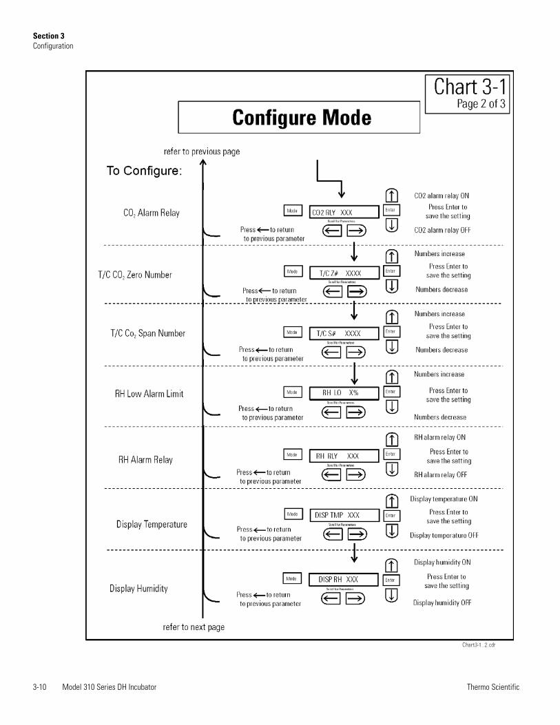
Set New Zero Numberfor T/C CO2 Sensors
High and Low CO2 alarms can be programmed to trip the remote alarmcontacts. A setting of ON allows it, a setting of OFF will not allow theCO2 alarms to trip the contacts. The factory setting is ON.
1. Press the Mode key until the Config indicator lights.
2. Press the right arrow until CO2 Rly XXX is displayed in the messagecenter.
3. Press up/down arrow to toggle the setting ON/OFF.
4. Press Enter to save the setting.
5. Press the Mode key to return to Run Mode or right/left to go tonext/previous parameter.
If a new T/C CO2 sensor is being installed, the two numbers on thefactory installed sticker on the T/C cell must be entered to calibrate theCO2 in the unit.
Note For the technician’s convenience, a label containing the two numberson the T/C cell is affixed inside the electronics drawer. s
1. Press the Mode key until the Config indicator lights.
2. Press the right arrow until T/CZ# XXXX is displayed in the messagecenter.
3. Press up/down arrow to change the zero number to match the sticker.
4. Press Enter to save the setting.
5. Press the Mode key to return to Run mode or right/left to go tonext/previous parameter.
3-4 Model 310 Series DH Incubator Thermo Scientific
Section 3Configuration
Enable CO2 Alarms toTrip Contacts
Set a Low RH AlarmLimit
If a new T/C CO2 sensor is being installed, the two numbers on thefactory installed sticker on the T/C cell must be entered to calibrate theCO2 in the unit.
Note For the technician’s convenience, a label containing the two numberson the T/C cell is affixed inside the electronics drawer. s
1. Press the Mode key until the Config indicator lights.
2. Press the right arrow until T/CS# XXXX is displayed in the messagecenter.
3. Press up/down arrow to change the span number to match the sticker.
4. Press Enter to save the setting.
5. Press the Mode key to return to Run mode or right/left to go tonext/previous parameter.
On units that have the RH option installed, a low RH alarm limit may beentered. The low RH alarm limit is the %RH in the cabinet which willcause a low RH alarm. The setpoint is variable from setpoint 0 to 90%RH The factory setting is 0% RH which disables the alarm.
1. Press the Mode key until the Config indicator lights.
2. Press the right arrow until RH Lo XX is displayed in the messagecenter.
3. Press up/down arrow to change the RH low alarm limit.
4. Press Enter to save the RH low alarm limit.
5. Press the Mode key to return to Run mode or right/left to go tonext/previous parameter.
Model 310 Series DH Incubator 3-5Thermo Scientific
Section 3Configuration
Set New Span Numberfor T/C CO2 Sensors
The low RH alarm can be programmed to trip the remote alarm contacts.A setting of ON will cause this, a setting of OFF will not allow the RHalarm to trip the contacts. The factory setting is ON.
1. Press the Mode key until the Config indicator lights.
2. Press the right arrow until RH Rly XXX is displayed in the messagecenter.
3. Press up/down arrow to toggle the setting ON/OFF.
4. Press Enter to save the setting.
5. Press the Mode key to return to Run mode or right/left to go tonext/previous parameter.
On units that are equipped with the RH option, the upper seven segmentdisplay on the control panel can be configured to display Tempcontinuously, RH continuously, or toggle between Temp and RH. If theunits does not have RH, the upper display will always display temperature.If temperature is set to ON and the RH is set OFF, temperature will bedisplayed continuously. If temperature is set to OFF and RH is set toON, RH will be displayed continuously. If both are turned ON, thedisplay will toggle between the two. The factory setting will default totoggle mode if the RH option is present.
1. Press the Mode key until the Config indicator lights.
2. Press the right arrow until Disp Tmp XXX or Disp RH XXX isdisplayed in the message center.
3. Press up/down arrow to toggle the setting ON/OFF.
4. Press Enter to save the setting.
5. Press the Mode key to return to Run mode or right/left to go tonext/previous parameter.
3-6 Model 310 Series DH Incubator Thermo Scientific
Section 3Configuration
Enable Temp/RH to beDisplayed
Enable RH Alarms toTrip Contacts
On units equipped with the Gas Guard option, a primary tank can beselected. The primary tank will be either Tank 1 or 2. The factory settingis Tank1.
1. Press the Mode key until the Config indicator lights.
2. Press the right arrow until Tnk Sel X is displayed in the messagecenter.
3. Press up/down arrow to toggle the setting between 1 and 2.
4. Press Enter to save the setting.
5. Press the Mode key to return to Run mode or right/left to go tonext/previous parameter.
On units equipped with the Gas Guard option, the Gas Guard systemmay be turned ON, or OFF if not in use. The factory setting is ON.
1. Press the Mode key until the Config indicator lights.
2. Press the right arrow until Gas Grd XX is displayed in the messagecenter.
3. Press up/down arrow to toggle the setting ON/OFF.
4. Press Enter to save the setting.
5. Press the Mode key to return to Run mode or right/left to go tonext/previous parameter.
Model 310 Series DH Incubator 3-7Thermo Scientific
Section 3Configuration
Select Primary Tankw/ Gas Guard Option
Disable the GasGuard System
On units that have the RS485 option, direct communication with theModel 1535 alarm system can be established. Each piece of equipmentconnected to the 1535 must have a unique address. An address of 0-24 canbe entered for the incubator. A setting of 0 is an invalid address that the1535 will ignore. The factory setting for the RS485 address is 0.
1. Press the Mode key until the Config indicator lights.
2. Press the right arrow until RS485 XX is displayed in the messagecenter.
3. Press up/down arrow to move the RS485 address.
4. Press Enter to save the RS485 address.
5. Press the Mode key to return to Run mode or right/left to go tonext/previous parameter.
3-8 Model 310 Series DH Incubator Thermo Scientific
Section 3Configuration
CommunicationsAddress for RS485
Model 310 Series DH Incubator 3-9Thermo Scientific
Section 3Configuration
3-10 Model 310 Series DH Incubator Thermo Scientific
Section 3Configuration
Model 310 Series DH Incubator 3-11Thermo Scientific
Section 3Configuration

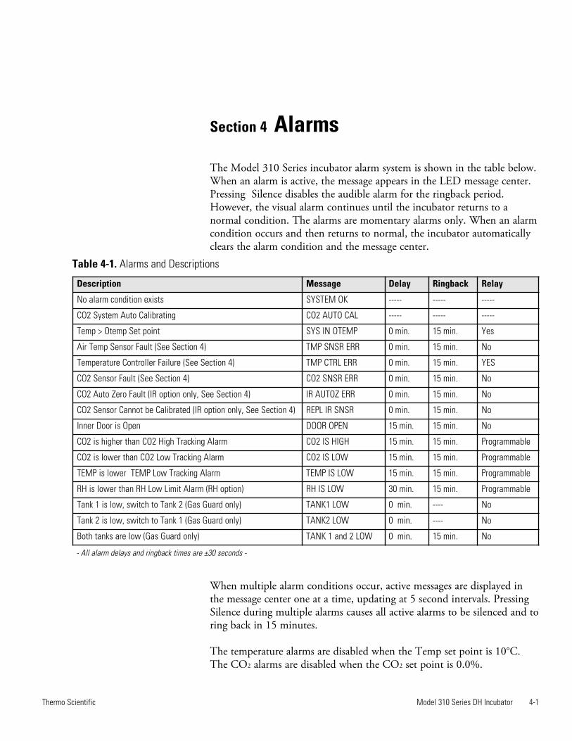
Table 4-1. Alarms and Descriptions
Model 310 Series DH Incubator 4-1Thermo Scientific
Section 4 Alarms
The Model 310 Series incubator alarm system is shown in the table below.When an alarm is active, the message appears in the LED message center.Pressing Silence disables the audible alarm for the ringback period.However, the visual alarm continues until the incubator returns to anormal condition. The alarms are momentary alarms only. When an alarmcondition occurs and then returns to normal, the incubator automaticallyclears the alarm condition and the message center.
When multiple alarm conditions occur, active messages are displayed inthe message center one at a time, updating at 5 second intervals. PressingSilence during multiple alarms causes all active alarms to be silenced and toring back in 15 minutes.
The temperature alarms are disabled when the Temp set point is 10°C.The CO2 alarms are disabled when the CO2 set point is 0.0%.
Description Message Delay Ringback Relay
No alarm condition exists SYSTEM OK ----- ----- -----
CO2 System Auto Calibrating CO2 AUTO CAL ----- ----- -----
Temp > Otemp Set point SYS IN OTEMP 0 min. 15 min. Yes
Air Temp Sensor Fault (See Section 4) TMP SNSR ERR 0 min. 15 min. No
Temperature Controller Failure (See Section 4) TMP CTRL ERR 0 min. 15 min. YES
CO2 Sensor Fault (See Section 4) CO2 SNSR ERR 0 min. 15 min. No
CO2 Auto Zero Fault (IR option only, See Section 4) IR AUTOZ ERR 0 min. 15 min. No
CO2 Sensor Cannot be Calibrated (IR option only, See Section 4) REPL IR SNSR 0 min. 15 min. No
Inner Door is Open DOOR OPEN 15 min. 15 min. No
CO2 is higher than CO2 High Tracking Alarm CO2 IS HIGH 15 min. 15 min. Programmable
CO2 is lower than CO2 Low Tracking Alarm CO2 IS LOW 15 min. 15 min. Programmable
TEMP is lower TEMP Low Tracking Alarm TEMP IS LOW 15 min. 15 min. Programmable
RH is lower than RH Low Limit Alarm (RH option) RH IS LOW 30 min. 15 min. Programmable
Tank 1 is low, switch to Tank 2 (Gas Guard only) TANK1 LOW 0 min. ---- No
Tank 2 is low, switch to Tank 1 (Gas Guard only) TANK2 LOW 0 min. ---- No
Both tanks are low (Gas Guard only) TANK 1 and 2 LOW 0 min. 15 min. No
- All alarm delays and ringback times are ±30 seconds -
4-2 Model 310 Series DH Incubator Thermo Scientific
Section 4Alarms
Temp Control FailureAlarm TMP CNTR ERR
In addition to other safety features designed into Model 310 Seriesincubators, a thermostat is also provided to monitor the cabinet’stemperature. In the unlikely event of a temperature control failure, thethermostat will turn off all heaters at a cabinet temperature of 65°C,±10%. This is intended to be a safety feature to protect the incubator, andis not intended to protect the cell cultures or the equipment inside thechamber should a temperature control failure occur.
The microprocessor in Model 310 Series incubators continually scans allavailable sensors to ensure that they are operating properly. Should an errorbe detected, the incubator sounds an alarm and displays the appropriatemessage. If such an alarm occurs, contact your local distributor or theTechnical Services department at 740-373-4763 or 1-800-438-4851 (USAand Canada) or fax 740-373-4189.
If the cables or connectors between the main microprocessor board and theCO2 sensor or between the CO2 board and the sensor head on the I/RCO2 units become loose or disconnected, the CO2 SENS ERR alarmoccurs.
I/R Units
On I/R incubators, the red light on the I/R module (see Figure 5-8 formodule circuit board location) will be lit continuously if communication islost between the CO2 board and the sensor head. The CO2 display willalso be locked at 00.0 without injection. Turning the incubator Off andOn will not clear the alarm. Only proper connection of all componentswill correct the alarm.
On incubators equipped with I/R CO2 control, calibration is doneautomatically using an auto zero system. Auto zero occurs once every 24hours. If, during the auto zero cycle, a CO2 correction of more than 0.45%is detected, the IR AUTOZ ERR alarm occurs.
Sensor Fault Alarms
CO2 SNSR ERR
IR AUTOZ ERR
Model 310 Series DH Incubator 4-3Thermo Scientific
Section 4Alarms
Possible problems which cause this alarm are:
• Auto Zero pump, orifice, filter or tubing will not let air to the sensor.
Possibilities are: Defective or electrically disconnected air pumpKinked auto zero vinyl tubingDisconnected tubing between the air pump and the sensorPlugged filter or orifice on the auto zero assemblyDefective auto zero circuit
• Cabinet temperature has been increased significantly from a previoussetpoint. For example, the unit was calibrated and operating at 30°Cand the setpoint is increased to 50°C. In this example, calibrating theCO2 will correct the alarm.
• High background CO2 in the laboratory. This could be from leaks inthe tank, regulator or vinyl CO2 tubing.
• High CO2 sensor calibration drift. This will require replacement of thesensor.
• Calibration of the CO2 system to less than 3% actual CO2. If this hasoccurred, contact the Technical Services Department.
IR AUTOZ ERR(continued)
4-4 Model 310 Series DH Incubator Thermo Scientific
PREV
ENTI
VE M
AIN
TEN
AN
CE
Incu
bato
rs
Yo
ur e
quip
men
t has
bee
n th
orou
ghly
test
ed a
nd c
alib
rate
d be
fore
ship
men
t. R
egul
ar p
reve
ntiv
e m
aint
enan
ce is
impo
rtan
t to
keep
you
r uni
t fu
nctio
ning
pro
perly
. The
ope
rato
r sho
uld
perf
orm
rout
ine
clea
ning
and
mai
nten
ance
on
a re
gula
r bas
is. F
or m
axim
um p
erfo
rman
ce a
nd
effic
ienc
y, it
is re
com
men
ded
the
unit
be c
heck
ed a
nd c
alib
rate
d pe
riodi
cally
by
a qu
alifi
ed se
rvic
e te
chni
cian
. T
he fo
llow
ing
is a
cond
ense
d lis
t of p
reve
ntiv
e m
aint
enan
ce re
quire
men
ts. S
ee th
e sp
ecifi
ed se
ctio
n of
the
oper
atin
g m
anua
l for
furt
her
deta
ils.
The
rmo
Fish
er S
cien
tific
has
qua
lifie
d se
rvic
e te
chni
cian
s, us
ing
NIS
T tr
acea
ble
inst
rum
ents
, ava
ilabl
e in
man
y ar
eas.
For m
ore
info
rmat
ion
on P
reve
ntiv
e M
aint
enan
ce o
r Ext
ende
d W
arra
ntie
s, pl
ease
con
tact
Tec
hnic
al S
ervi
ces.
Cle
anin
g an
d ca
libra
tion
adju
stm
ent i
nter
vals
are
depe
nden
t upo
n us
e, e
nviro
nmen
tal c
ondi
tions
and
acc
urac
y re
quire
d.
Tip
s for
all
incu
bato
rs:
D
o N
OT
use
ble
ach
or a
ny d
isinf
ecta
nt th
at h
as h
igh
chlo
ros
U
se st
erile
, dist
illed
or d
emin
eral
ized
wat
er.
A
void
spra
ying
cle
aner
on
the
CO
2 sen
sor.
D
o no
t use
pow
dere
d gl
oves
for t
issue
cul
ture
s.
Model 310 Series DH Incubator 4-5Thermo Scientific
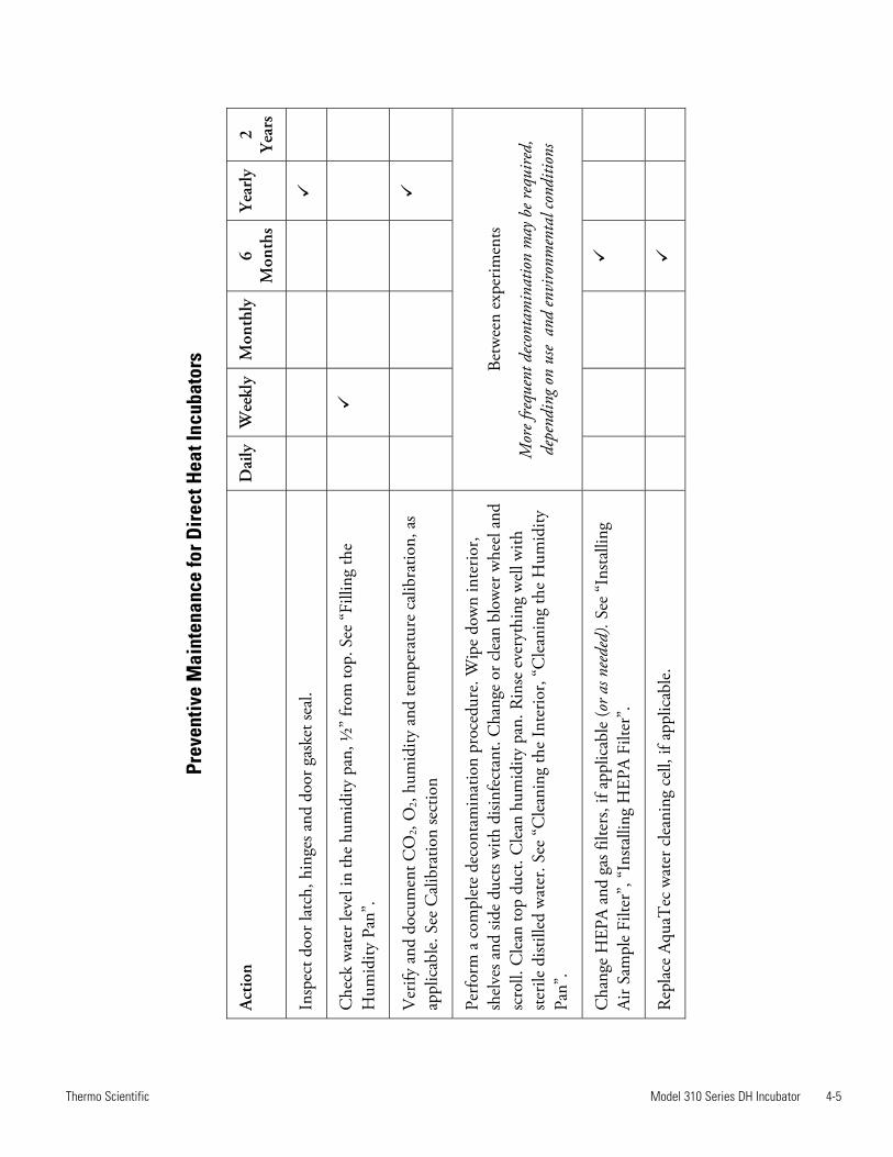
Prev
entiv
e M
aint
enan
ce fo
r Dire
ct H
eat I
ncub
ator
s
Act
ion
Dai
ly
Wee
kly
Mon
thly
6 M
onth
sY
earl
y2
Yea
rs
Insp
ect d
oor l
atch
, hin
ges a
nd d
oor g
aske
t sea
l.
Che
ck w
ater
leve
l in
the
hum
idity
pan
, ½”
from
top.
See
“Fi
lling
the
Hum
idity
Pan
”.
Ver
ify a
nd d
ocum
ent C
O2,
O2,
hum
idity
and
tem
pera
ture
cal
ibra
tion,
as
appl
icab
le. S
ee C
alib
ratio
n se
ctio
n
Perf
orm
a c
ompl
ete
deco
ntam
inat
ion
proc
edur
e. W
ipe
dow
n in
teri
or,
shel
ves a
nd si
de d
ucts
with
disi
nfec
tant
. Cha
nge
or c
lean
blo
wer
whe
el a
nd
scro
ll. C
lean
top
duct
. Cle
an h
umid
ity p
an. R
inse
eve
ryth
ing
wel
l with
st
erile
dist
illed
wat
er. S
ee “
Cle
anin
g th
e In
terio
r, “C
lean
ing
the
Hum
idity
Pa
n”.
Betw
een
expe
rim
ents
Mor
e fre
quen
t dec
onta
min
atio
n m
ay b
e req
uire
d,
depe
ndin
g on
use
and
envi
ronm
enta
l con
ditio
ns
Cha
nge
HEP
A a
nd g
as fi
lters
, if a
pplic
able
(or a
s nee
ded)
. See
“In
stal
ling
Air
Sam
ple
Filte
r”, “
Inst
allin
g H
EPA
Filt
er”.
Rep
lace
Aqu
aTec
wat
er c
lean
ing
cell,
if a
pplic
able
.

Model 310 Series DH Incubator 5-1Thermo Scientific
Section 5 Routine Maintenance
Warning If the unit has been in service, turn it off and disconnect thepower cord connector before proceeding with any maintenance. s
Caution Before using any cleaning or decontamination method exceptthose recommended by the manufacturer, users must check with themanufacturer that the proposed method will not damage the equipment. s
Use an appropriate disinfectant. All articles and surfaces to be disinfectedmust be thoroughly cleaned, rinsed with sterile water, and rough dried.
Warning Alcohol, even a 70% solution, is volatile and flammable. Use itonly in a well ventilated area that is free from open flame. If anycomponent is cleaned with alcohol, do not expose the component to openflame or other possible hazard.Do not spray T/C sensor with flammable solutions. The internaltemperature of the CO2 sensor is approximately 150°C when the unit is inoperation. Allow sufficient time for the sensor to cool before cleaning. s
Caution Do not use strong alkaline or caustic agents. Stainless steel iscorrosion resistant, not corrosion-proof. Do not use solutions of sodiumhypochlorite (bleach) as they may also cause pitting and rusting. s
1. Remove the shelves, HEPA filter (a factory installed option), accessport filter, sample air filter, left and right duct sheets and the top duct.The top duct requires the two wing nuts to be removed.
2. Set the HEPA filter aside. Wash the shelves, ducts, wing nuts andstopper with disinfectant. Optional: The shelves, ducts and wing nutsmay be autoclaved.
3. Remove the blower scroll held on by four screws. Remove the blowerwheel and the access port filter. If a new blower wheel and scroll aregoing to be used, discard the old ones. If the old ones are beingreused, wash and rinse all parts with disinfectant.
Disinfecting theIncubator Interior
4. The CO2 sensor may be lowered by unscrewing the retaining ringaround the sensor. This will allow the sensor gasket to be removed,cleaned and replaced. WIPE the CO2 sensor, do not spray or soak.
5. Wash the inner door gasket with disinfectant. The inner door gasketmay be removed and/or replaced.
6. Wash the cabinet interior with disinfectant, starting at the top andworking down. Refer to the disinfectant directions for length of timeneeded before rinsing. Wash the inner door both inside and out. Thecabinet and door must be rinsed with sterile water until thedisinfectant has been removed. After the cabinet has been rinsed, spraywith 70% alcohol.
7. If the CO2 sensor gasket was removed, spray it with 70% alcohol andinstall it. Install the sample filter.
8. Install the top duct, left and right ducts, inner door gasket, and accessport stopper spraying each with 70% alcohol.
9. Install new HEPA Filter.
10. Install the shelves and spray with 70% alcohol.
Clean the incubator exterior with a damp sponge or soft, well-wrung clothand mild detergent dissolved in water. Dry with a soft cloth.
The chamber glass door and the optional independent inner glass doorsmay be cleaned using the same disinfectant used on the incubator interior.It is imperative that they be rinsed with sterile distilled water to removethe disinfectant residue. The doors should then be dried with a soft cloth.
Precautions in the cleaning and care of the incubator glass doors:Moisture leaches alkaline materials (sodium, Na) from the surface of theglass. Evaporation of the moisture concentrates the alkaline and mayproduce a white staining or clouding of the glass surface. Cleaningchemicals with a pH above 9 and heat (autoclaving) accelerate the corro-sion process. Therefore, it is very important to rinse and dry the glassdoors after cleaning. Autoclaving the glass doors should be avoided.
There is no simple method for repairing corroded glass. In most cases,the glass must be replaced.
5-2 Model 310 Series DH Incubator Thermo Scientific
Section 5Routine Maintenance
Cleaning the GlassDoors
Cleaning the CabinetExterior
Disinfecting theInterior (cont.)
Clean the humidity pan with soap and water and a general use laboratorydisinfectant. Rinse with sterile water and spray with 70% alcohol. Thehumidity pan may be autoclaved.
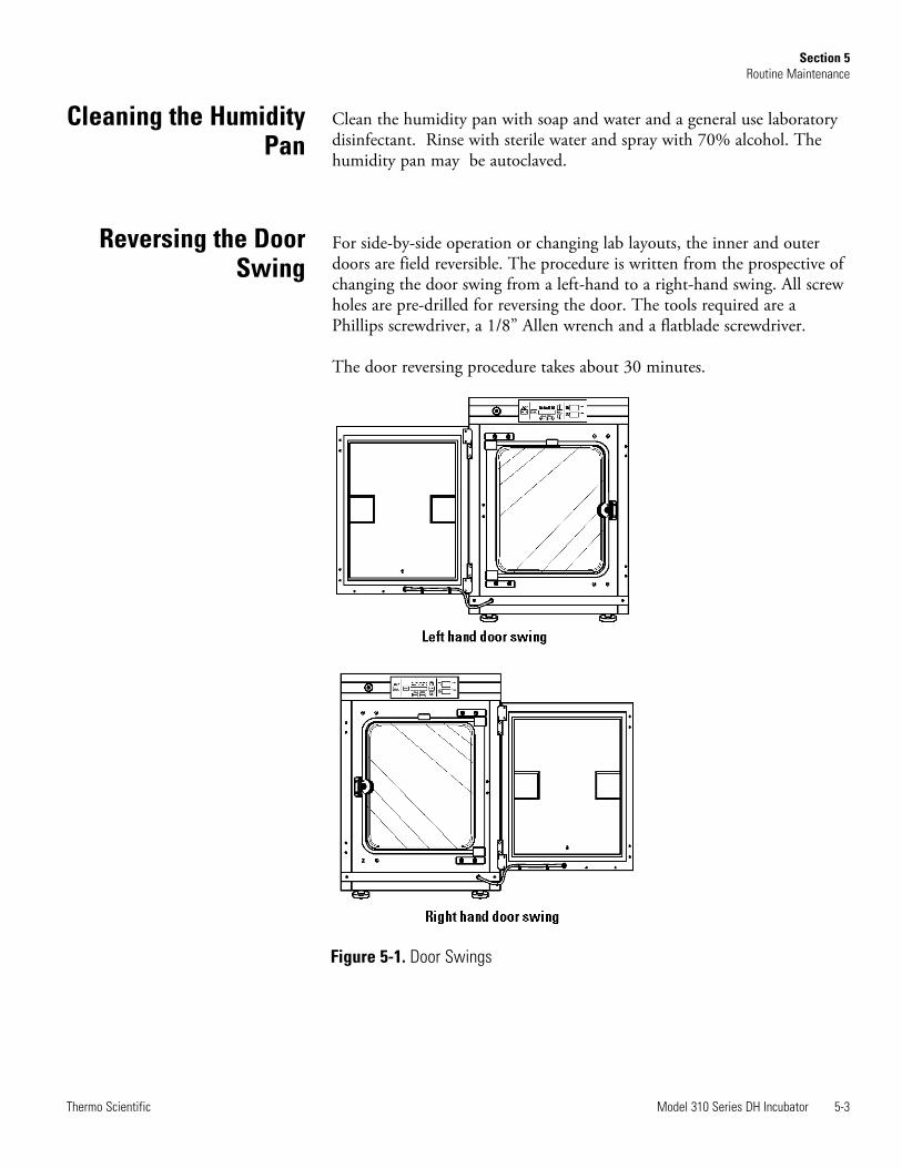
For side-by-side operation or changing lab layouts, the inner and outerdoors are field reversible. The procedure is written from the prospective ofchanging the door swing from a left-hand to a right-hand swing. All screwholes are pre-drilled for reversing the door. The tools required are aPhillips screwdriver, a 1/8” Allen wrench and a flatblade screwdriver.
The door reversing procedure takes about 30 minutes.
Model 310 Series DH Incubator 5-3Thermo Scientific
Section 5Routine Maintenance
Reversing the DoorSwing
Cleaning the HumidityPan
Figure 5-1. Door Swings
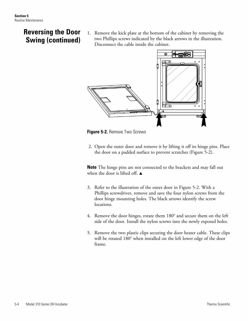
1. Remove the kick plate at the bottom of the cabinet by removing thetwo Phillips screws indicated by the black arrows in the illustration.Disconnect the cable inside the cabinet.
2. Open the outer door and remove it by lifting it off its hinge pins. Placethe door on a padded surface to prevent scratches (Figure 5-2).
Note The hinge pins are not connected to the brackets and may fall outwhen the door is lifted off. s
3. Refer to the illustration of the outer door in Figure 5-2. With aPhillips screwdriver, remove and save the four nylon screws from thedoor hinge mounting holes. The black arrows identify the screwlocations.
4. Remove the door hinges, rotate them 180° and secure them on the leftside of the door. Install the nylon screws into the newly exposed holes.
5. Remove the two plastic clips securing the door heater cable. These clipswill be rotated 180° when installed on the left lower edge of the doorframe.
5-4 Model 310 Series DH Incubator Thermo Scientific
Section 5Routine Maintenance
Figure 5-2. Remove Two Screws
Reversing the DoorSwing (continued)

6. Rotate the kick plate and attach the door heater cable with the clips asshown in Figure 5-3. The insert in the illustration shows the properpositioning of the clips.
7. The incubator and door should look similar to Figure 5-4.
Model 310 Series DH Incubator 5-5Thermo Scientific
Section 5Routine Maintenance
Figure 5-3. Rotate Kickplate
Figure 5-4. Unit with Detached Door
Reversing the DoorSwing (continued)
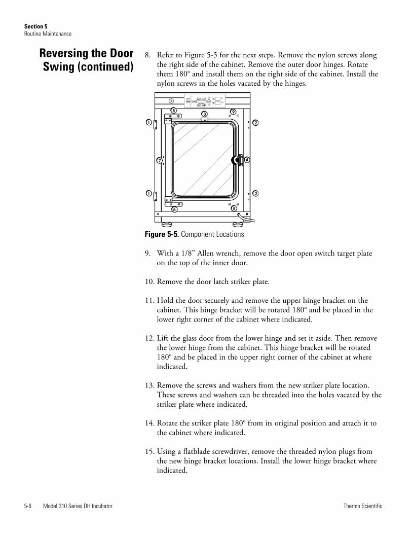
8. Refer to Figure 5-5 for the next steps. Remove the nylon screws alongthe right side of the cabinet. Remove the outer door hinges. Rotatethem 180° and install them on the right side of the cabinet. Install thenylon screws in the holes vacated by the hinges.
9. With a 1/8” Allen wrench, remove the door open switch target plateon the top of the inner door.
10. Remove the door latch striker plate.
11. Hold the door securely and remove the upper hinge bracket on thecabinet. This hinge bracket will be rotated 180° and be placed in thelower right corner of the cabinet where indicated.
12. Lift the glass door from the lower hinge and set it aside. Then removethe lower hinge from the cabinet. This hinge bracket will be rotated180° and be placed in the upper right corner of the cabinet at whereindicated.
13. Remove the screws and washers from the new striker plate location.These screws and washers can be threaded into the holes vacated by thestriker plate where indicated.
14. Rotate the striker plate 180° from its original position and attach it tothe cabinet where indicated.
15. Using a flatblade screwdriver, remove the threaded nylon plugs fromthe new hinge bracket locations. Install the lower hinge bracket whereindicated.
5-6 Model 310 Series DH Incubator Thermo Scientific
Section 5Routine Maintenance
Figure 5-5. Component Locations
Reversing the DoorSwing (continued)
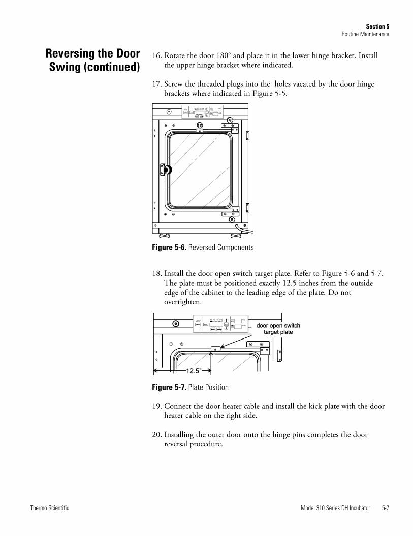
16. Rotate the door 180° and place it in the lower hinge bracket. Installthe upper hinge bracket where indicated.
17. Screw the threaded plugs into the holes vacated by the door hingebrackets where indicated in Figure 5-5.
18. Install the door open switch target plate. Refer to Figure 5-6 and 5-7.The plate must be positioned exactly 12.5 inches from the outsideedge of the cabinet to the leading edge of the plate. Do notovertighten.
19. Connect the door heater cable and install the kick plate with the doorheater cable on the right side.
20. Installing the outer door onto the hinge pins completes the doorreversal procedure.
Model 310 Series DH Incubator 5-7Thermo Scientific
Section 5Routine Maintenance
Figure 5-6. Reversed Components
Figure 5-7. Plate Position
Reversing the DoorSwing (continued)
Replace the HEPA filter routinely on an annual basis, or more often if itchanges color. The filter should also be changed when the chamber iscleaned.
Warning The electronics section contains hazardous voltages. Onlyqualified service personnel should access this area. s
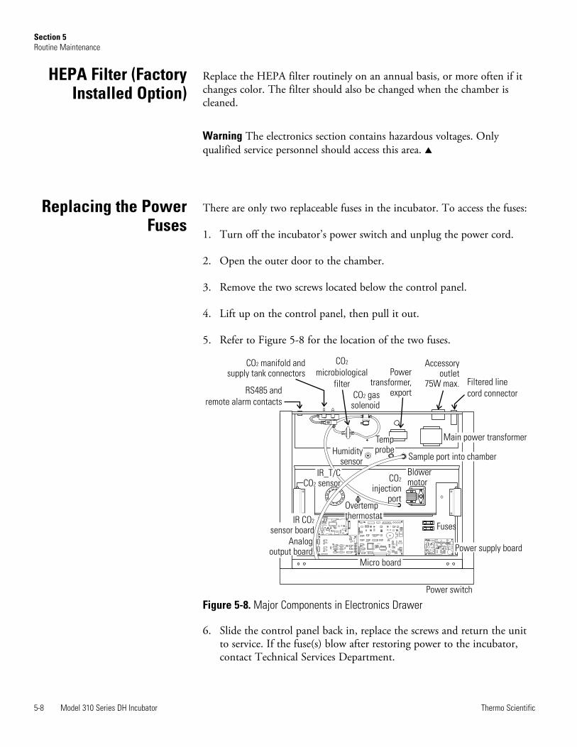
There are only two replaceable fuses in the incubator. To access the fuses:
1. Turn off the incubator’s power switch and unplug the power cord.
2. Open the outer door to the chamber.
3. Remove the two screws located below the control panel.
4. Lift up on the control panel, then pull it out.
5. Refer to Figure 5-8 for the location of the two fuses.
6. Slide the control panel back in, replace the screws and return the unitto service. If the fuse(s) blow after restoring power to the incubator,contact Technical Services Department.
5-8 Model 310 Series DH Incubator Thermo Scientific
Section 5Routine Maintenance
Replacing the PowerFuses
Forma
Power switch
Fuses
COinjection
port
2
Filtered line
cord connector
Accessoryoutlet
75W max.
Powertransformer,
exportCO gassolenoid
2
CO
microbiological
filter
2CO manifold andsupply tank connectors
2
RS485 and
remote alarm contacts
Main power transformerTempprobe
Sample port into chamberHumidity
sensor
Overtempthermostat
IR_T/CCO sensor2
Blowermotor
Power supply board
Micro board
IR COsensor board
2
Analogoutput board
Figure 5-8. Major Components in Electronics Drawer
HEPA Filter (FactoryInstalled Option)
Electronics Section
Expanded descriptions for some of the components indicated in Figure 5-8follow.
Power Switch - Located beneath the control panel. The outer door mustbe open to access the switch.
RS 485 and Remote Alarm Contacts - Connectors and auxiliary wirethrough port
CO2 manifold and supply tank connectors - Part of the Gas Guard sys-tem, a factory installed option.
Humidity sensor (optional)Analog output board - 4-20 mA, 0-1 Volt, 0-5 Volt
1. Turn off the incubator’s power switch and unplug the power cord.
2. Remove the two screws from the front of the cabinet top and the twoscrews in the uppermost corners of the back panel.
3. Slide the top about an inch to the rear and lift it off.
Note There are small locking tabs in the back which will be bent if the topis lifted off without sliding it first to the back. s
Model 310 Series DH Incubator 5-9Thermo Scientific
Section 5Routine Maintenance
Major Components
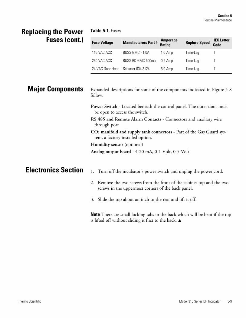
Fuse Voltage Manufacturers Part # AmperageRating Rupture Speed IEC Letter
Code
115 VAC ACC BUSS GMC - 1.0A 1.0 Amp Time-Lag T
230 VAC ACC BUSS BK-GMC-500ma 0.5 Amp Time-Lag T
24 VAC Door Heat Schurter 034.3124 5.0 Amp Time-Lag T
Table 5-1. FusesReplacing the PowerFuses (cont.)
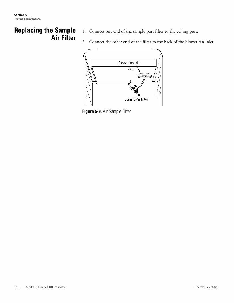
1. Connect one end of the sample port filter to the ceiling port.
2. Connect the other end of the filter to the back of the blower fan inlet.
Figure 5-9. Air Sample Filter
5-10 Model 310 Series DH Incubator Thermo Scientific
Section 5Routine Maintenance
Replacing the SampleAir Filter
Section 6 Factory Options
Descriptions for connections to external equipment follow.
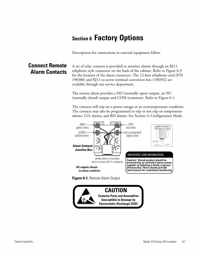
A set of relay contacts is provided to monitor alarms through an RJ11telephone style connector on the back of the cabinet. Refer to Figure 6-3for the location of the alarm connector. The 12-foot telephone cord (P/N190388) and RJ11-to-screw terminal conversion box (190392) areavailable through our service department.
The remote alarm provides a NO (normally open) output, an NC(normally closed) output and COM (common). Refer to Figure 6-1.
The contacts will trip on a power outage or an overtemperature condition.The contacts may also be programmed to trip or not trip on temperaturealarms, CO2 alarms, and RH alarms. See Section 3, Configuration Mode.
Figure 6-1. Remote Alarm Output
Model 310 Series DH Incubator 6-1Thermo Scientific
Connect RemoteAlarm Contacts
Contains Parts and Assemblies
Susceptible to Damage by
Electrostatic Discharge (ESD)
CAUTION
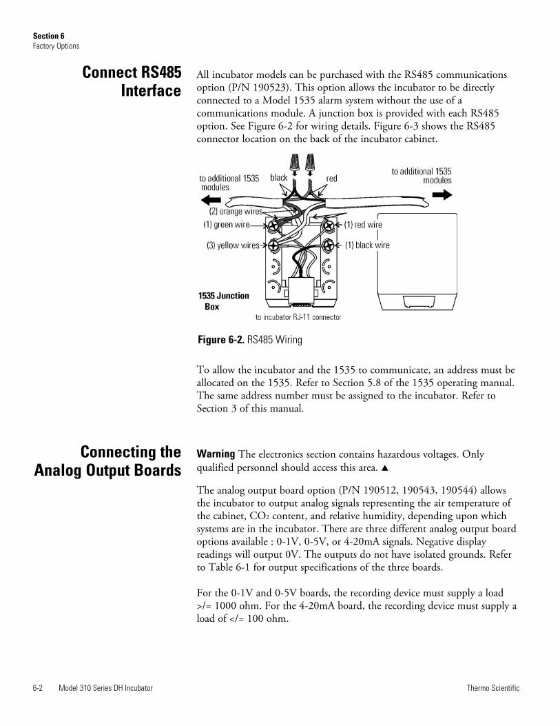
All incubator models can be purchased with the RS485 communicationsoption (P/N 190523). This option allows the incubator to be directlyconnected to a Model 1535 alarm system without the use of acommunications module. A junction box is provided with each RS485option. See Figure 6-2 for wiring details. Figure 6-3 shows the RS485connector location on the back of the incubator cabinet.
To allow the incubator and the 1535 to communicate, an address must beallocated on the 1535. Refer to Section 5.8 of the 1535 operating manual.The same address number must be assigned to the incubator. Refer toSection 3 of this manual.
Warning The electronics section contains hazardous voltages. Onlyqualified personnel should access this area. s
The analog output board option (P/N 190512, 190543, 190544) allowsthe incubator to output analog signals representing the air temperature ofthe cabinet, CO2 content, and relative humidity, depending upon whichsystems are in the incubator. There are three different analog output boardoptions available : 0-1V, 0-5V, or 4-20mA signals. Negative displayreadings will output 0V. The outputs do not have isolated grounds. Referto Table 6-1 for output specifications of the three boards.
For the 0-1V and 0-5V boards, the recording device must supply a load>/= 1000 ohm. For the 4-20mA board, the recording device must supply aload of </= 100 ohm.
6-2 Model 310 Series DH Incubator Thermo Scientific
Section 6Factory Options
Connect RS485Interface
Connecting theAnalog Output Boards
Figure 6-2. RS485 Wiring
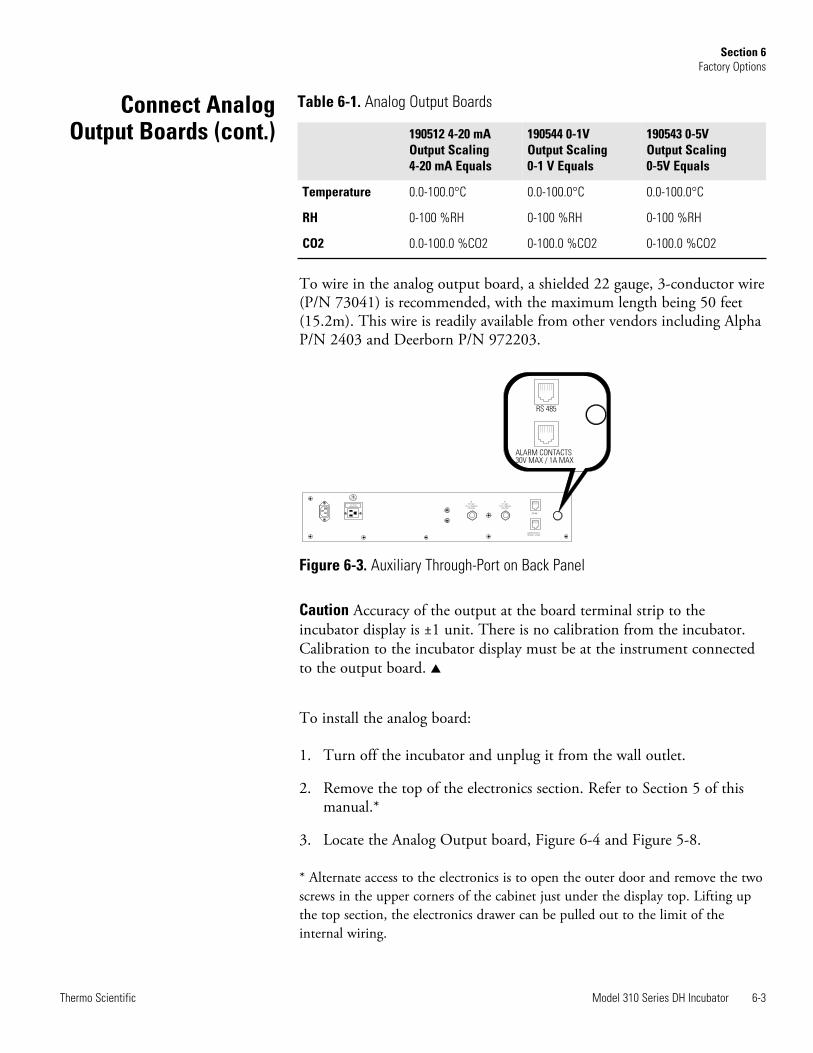
Model 310 Series DH Incubator 6-3Thermo Scientific
Section 6Factory Options
To wire in the analog output board, a shielded 22 gauge, 3-conductor wire(P/N 73041) is recommended, with the maximum length being 50 feet(15.2m). This wire is readily available from other vendors including AlphaP/N 2403 and Deerborn P/N 972203.
Figure 6-3. Auxiliary Through-Port on Back Panel
Caution Accuracy of the output at the board terminal strip to theincubator display is ±1 unit. There is no calibration from the incubator.Calibration to the incubator display must be at the instrument connectedto the output board. s
To install the analog board:
1. Turn off the incubator and unplug it from the wall outlet.
2. Remove the top of the electronics section. Refer to Section 5 of thismanual.*
3. Locate the Analog Output board, Figure 6-4 and Figure 5-8.
* Alternate access to the electronics is to open the outer door and remove the twoscrews in the upper corners of the cabinet just under the display top. Lifting upthe top section, the electronics drawer can be pulled out to the limit of theinternal wiring.
RS 485
ALARM CONTACTS30V MAX / 1A MAX
ACCESSORY
75 WATTS MAX.
RS 485
ALARM CONTACTS
30V MAX / 1A MAX
#2
CO inject
15 p.s.i. Regulated
(103.4 kPa)
#1
CO inject
15 p.s.i. Regulated
(103.4 kPa)
2 2
190512 4-20 mA Output Scaling 4-20 mA Equals
190544 0-1V Output Scaling 0-1 V Equals
190543 0-5V Output Scaling 0-5V Equals
Temperature 0.0-100.0°C 0.0-100.0°C 0.0-100.0°C
RH 0-100 %RH 0-100 %RH 0-100 %RH
CO2 0.0-100.0 %CO2 0-100.0 %CO2 0-100.0 %CO2
Table 6-1. Analog Output BoardsConnect AnalogOutput Boards (cont.)
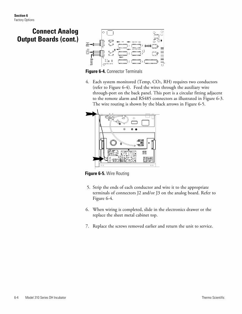
Figure 6-4. Connector Terminals
4. Each system monitored (Temp, CO2, RH) requires two conductors(refer to Figure 6-4). Feed the wires through the auxiliary wirethrough-port on the back panel. This port is a circular fitting adjacentto the remote alarm and RS485 connectors as illustrated in Figure 6-3.The wire routing is shown by the black arrows in Figure 6-5.
5. Strip the ends of each conductor and wire it to the appropriateterminals of connectors J2 and/or J3 on the analog board. Refer toFigure 6-4.
6. When wiring is completed, slide in the electronics drawer or thereplace the sheet metal cabinet top.
7. Replace the screws removed earlier and return the unit to service.
6-4 Model 310 Series DH Incubator Thermo Scientific
Section 6Factory Options
Figure 6-5. Wire Routing
Connect AnalogOutput Boards (cont.)
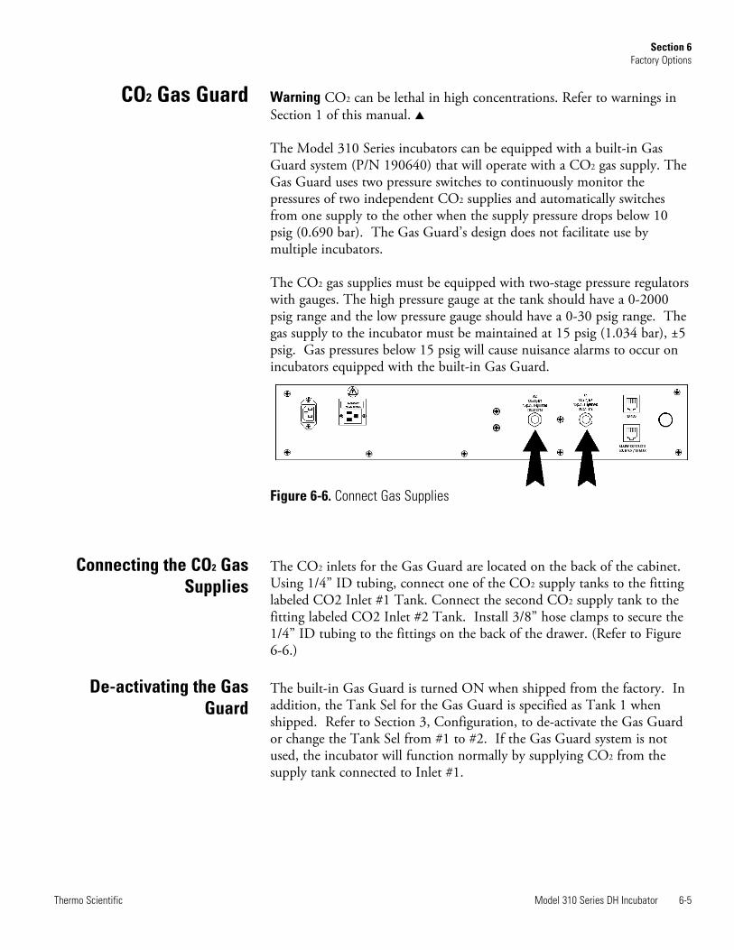
Warning CO2 can be lethal in high concentrations. Refer to warnings inSection 1 of this manual. s
The Model 310 Series incubators can be equipped with a built-in GasGuard system (P/N 190640) that will operate with a CO2 gas supply. TheGas Guard uses two pressure switches to continuously monitor thepressures of two independent CO2 supplies and automatically switchesfrom one supply to the other when the supply pressure drops below 10psig (0.690 bar). The Gas Guard’s design does not facilitate use bymultiple incubators.
The CO2 gas supplies must be equipped with two-stage pressure regulatorswith gauges. The high pressure gauge at the tank should have a 0-2000psig range and the low pressure gauge should have a 0-30 psig range. Thegas supply to the incubator must be maintained at 15 psig (1.034 bar), ±5psig. Gas pressures below 15 psig will cause nuisance alarms to occur onincubators equipped with the built-in Gas Guard.
The CO2 inlets for the Gas Guard are located on the back of the cabinet.Using 1/4” ID tubing, connect one of the CO2 supply tanks to the fittinglabeled CO2 Inlet #1 Tank. Connect the second CO2 supply tank to thefitting labeled CO2 Inlet #2 Tank. Install 3/8” hose clamps to secure the1/4” ID tubing to the fittings on the back of the drawer. (Refer to Figure6-6.)
The built-in Gas Guard is turned ON when shipped from the factory. Inaddition, the Tank Sel for the Gas Guard is specified as Tank 1 whenshipped. Refer to Section 3, Configuration, to de-activate the Gas Guardor change the Tank Sel from #1 to #2. If the Gas Guard system is notused, the incubator will function normally by supplying CO2 from thesupply tank connected to Inlet #1.
Model 310 Series DH Incubator 6-5Thermo Scientific
Section 6Factory Options
Figure 6-6. Connect Gas Supplies
De-activating the GasGuard
Connecting the CO2 GasSupplies
CO2 Gas Guard
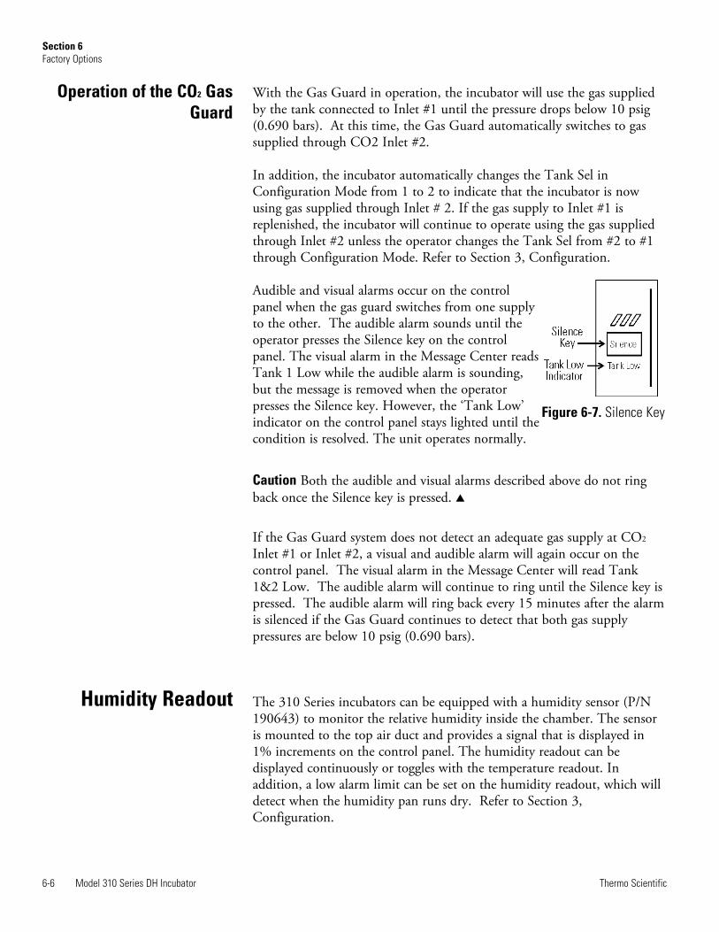
With the Gas Guard in operation, the incubator will use the gas suppliedby the tank connected to Inlet #1 until the pressure drops below 10 psig(0.690 bars). At this time, the Gas Guard automatically switches to gassupplied through CO2 Inlet #2.
In addition, the incubator automatically changes the Tank Sel inConfiguration Mode from 1 to 2 to indicate that the incubator is nowusing gas supplied through Inlet # 2. If the gas supply to Inlet #1 isreplenished, the incubator will continue to operate using the gas suppliedthrough Inlet #2 unless the operator changes the Tank Sel from #2 to #1through Configuration Mode. Refer to Section 3, Configuration.
Audible and visual alarms occur on the controlpanel when the gas guard switches from one supplyto the other. The audible alarm sounds until theoperator presses the Silence key on the controlpanel. The visual alarm in the Message Center readsTank 1 Low while the audible alarm is sounding,but the message is removed when the operatorpresses the Silence key. However, the ‘Tank Low’indicator on the control panel stays lighted until thecondition is resolved. The unit operates normally.
Caution Both the audible and visual alarms described above do not ringback once the Silence key is pressed. s
If the Gas Guard system does not detect an adequate gas supply at CO2
Inlet #1 or Inlet #2, a visual and audible alarm will again occur on thecontrol panel. The visual alarm in the Message Center will read Tank1&2 Low. The audible alarm will continue to ring until the Silence key ispressed. The audible alarm will ring back every 15 minutes after the alarmis silenced if the Gas Guard continues to detect that both gas supplypressures are below 10 psig (0.690 bars).
The 310 Series incubators can be equipped with a humidity sensor (P/N190643) to monitor the relative humidity inside the chamber. The sensoris mounted to the top air duct and provides a signal that is displayed in1% increments on the control panel. The humidity readout can bedisplayed continuously or toggles with the temperature readout. Inaddition, a low alarm limit can be set on the humidity readout, which willdetect when the humidity pan runs dry. Refer to Section 3,Configuration.
6-6 Model 310 Series DH Incubator Thermo Scientific
Section 6Factory Options
Humidity Readout
Operation of the CO2 GasGuard
Figure 6-7. Silence Key
• Water level in the humidity pan
• Frequency of door openings
• The humidity pan located on bottom of chamber versus a shelf.
Caution Incubators equipped with a Thermal Conductivity CO2 sensorrely on a constant level of relative humidity in order to accurately measureand control the CO2 concentration in the incubator. s
The sensor is capable of measuring relative humidity from 10% to 100%with an accuracy of ±5% above 90%. See Section 2, Calibration, fordetails on calibrating the humidity readout.
Warning The Uninterruptible Power Supply is not rated for life-supportapplications. s
The optional Uninterruptible Power Supply ([UPS] P/N 270078 and270082) provides a back-up power source for the incubator. When thebatteries are fully charged and the incubator operating at 37°C in an 18°Cambient temperature, the UPS provides approximately one hour ofuninterrupted power during a power failure. A higher operatingtemperature decreases this back-up time, a higher ambient temperatureincreases it. This estimated time assumes that the incubator will be alreadyat its operating temperature and that the incubator door will not beopened during the back-up period.
The remote alarm contacts will not trip during a power failure whileconnected to the UPS until battery power is exhausted. There is however,an audible and visual alarm when the unit switches to battery operation.
The UPS batteries are fully charged when the unit has been connected toutility power for a minimum of four hours. The UPS power switch doesnot have to be on for the batteries to charge. When battery replacementbecomes necessary, refer to the UPS user’s manual.
Caution Use only factory recommended UPS units which produce a puresine wave output. Other UPS units could damage the incubator and voidthe warranty. Typical facility back-up systems will not effect the efficiencyof the incubator. s
Model 310 Series DH Incubator 6-7Thermo Scientific
Section 6Factory Options
Uninterruptible PowerSupply Connections
Humidity Level Factors
Humidity ReadoutAccuracy
1. Plug the incubator line cord into one of the receptacles on the back ofthe UPS. Then plug the UPS line cord into a suitable wall outlet.
2. Turn the UPS power switch on.
Use the line cord supplied with the incubator to connect the UPS to asuitable wall outlet, and the UPS coupler to connect the incubator to theUPS.
Warning The Uninterruptible Power Supply contains potentiallyhazardous voltages even when not connected to line voltage.Do not attempt to disassemble UPS as it contains no user-serviceable parts.Repairs must be performed by factory trained service personnel. s
6-8 Model 310 Series DH Incubator Thermo Scientific
Section 6Factory Options
Connecting UPS P/N 270078, 115V, 50/60Hz
Connecting UPS P/N 270082, 230V, 50/60Hz
Section 7 Specifications
* Specifications are based on nominal voltages of 115V or 230V in ambient of 22°Cto 25°C.
TemperatureControl . . . .±0.1°C Microprocessor PID ControlSetpoint . . . . . . . . . . .Digital - Touch pad, 0.1°CRange . . . . . . . . . . . .+5°C above ambient to 50°CUniformity . . . . . . . . . . . . . . . . . .±0.3°C @ +37°CTracking alarm . . User programmable (low) indicatorOvertemp . .Tracking, user programmable, action, and indicatorDisplay . . . . . . . . .Digital, LED, 0.1°C increments
Temperature SafetyType . . Extreme temperature safety, action, and indicatorSensor . . Thermostat, independent of temperature control systemIndicator . . Message center, audible and visual alarms
Relative HumidityControl . . . . .Humidity pan - natural vaporizationHumidity with pan . . . . . . . . . . .95% RH at 37°CDisplay . . . . . . . . . . . . .Optional in 1% incrementsAlarm . . . . . . .Low RH with optional RH monitor
CO2
Control . . . . .±0.1% microprocessor PID controlSensor . . . . . . . . . . . . . . . . . . . . . . . . . . .T/C or IRReadability . . . . . . . . . . . . . . . . . . . . . . . . . . .0.1%Range . . . . . . . . . . . . . . . . . . . . . . . . . . . .0 to 20%Inlet pressure . . . . . . . . . . . . . . . . .15 psig, ±5 psigDisplay . . . . . . . . . .Digital LED, 0.1% increments
Model 310 Series DH Incubator 7-1Thermo Scientific
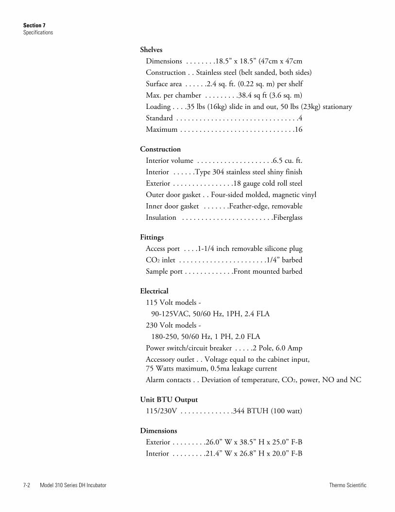
7-2 Model 310 Series DH Incubator Thermo Scientific
Section 7Specifications
ShelvesDimensions . . . . . . . .18.5” x 18.5” (47cm x 47cmConstruction . . Stainless steel (belt sanded, both sides)Surface area . . . . . .2.4 sq. ft. (0.22 sq. m) per shelfMax. per chamber . . . . . . . . .38.4 sq ft (3.6 sq. m)Loading . . . .35 lbs (16kg) slide in and out, 50 lbs (23kg) stationaryStandard . . . . . . . . . . . . . . . . . . . . . . . . . . . . . . . .4Maximum . . . . . . . . . . . . . . . . . . . . . . . . . . . . . .16
ConstructionInterior volume . . . . . . . . . . . . . . . . . . . .6.5 cu. ft.Interior . . . . . .Type 304 stainless steel shiny finishExterior . . . . . . . . . . . . . . . .18 gauge cold roll steelOuter door gasket . . Four-sided molded, magnetic vinylInner door gasket . . . . . . .Feather-edge, removableInsulation . . . . . . . . . . . . . . . . . . . . . . . .Fiberglass
FittingsAccess port . . . .1-1/4 inch removable silicone plugCO2 inlet . . . . . . . . . . . . . . . . . . . . . . .1/4” barbedSample port . . . . . . . . . . . . .Front mounted barbed
Electrical115 Volt models - 90-125VAC, 50/60 Hz, 1PH, 2.4 FLA230 Volt models - 180-250, 50/60 Hz, 1 PH, 2.0 FLAPower switch/circuit breaker . . . . .2 Pole, 6.0 AmpAccessory outlet . . Voltage equal to the cabinet input,75 Watts maximum, 0.5ma leakage currentAlarm contacts . . Deviation of temperature, CO2, power, NO and NC
Unit BTU Output115/230V . . . . . . . . . . . . . .344 BTUH (100 watt)
DimensionsExterior . . . . . . . . .26.0” W x 38.5” H x 25.0” F-BInterior . . . . . . . . .21.4” W x 26.8” H x 20.0” F-B
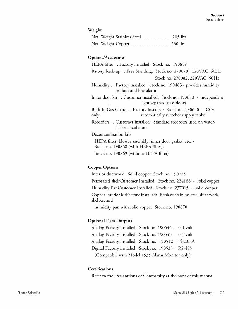
Model 310 Series DH Incubator 7-3Thermo Scientific
Section 7Specifications
WeightNet Weight Stainless Steel . . . . . . . . . . . . .205 lbsNet Weight Copper . . . . . . . . . . . . . . . . .230 lbs.
Options/AccessoriesHEPA filter . . Factory installed: Stock no. 190858Battery back-up . . Free Standing: Stock no. 270078, 120VAC, 60Hz Stock no. 270082, 220VAC, 50HzHumidity . . Factory installed: Stock no. 190463 - provides humidity readout and low alarmInner door kit . . Customer installed: Stock no. 190650 - independent . . . eight separate glass doorsBuilt-in Gas Guard . . Factory installed: Stock no. 190640 - CO2
only, automatically switches supply tanksRecorders . . Customer installed: Standard recorders used on water- jacket incubatorsDecontamination kits HEPA filter, blower assembly, inner door gasket, etc. - Stock no. 190868 (with HEPA filter), Stock no. 190869 (without HEPA filter)
Copper OptionsInterior ductwork .Solid copper: Stock no. 190725Perforated shelfCustomer Installed: Stock no. 224166 - solid copperHumidity PanCustomer Installed: Stock no. 237015 - solid copperCopper interior kitFactory installed: Replace stainless steel duct work,shelves, and humidity pan with solid copper Stock no. 190870
Optional Data OutputsAnalog Factory installed: Stock no. 190544 - 0-1 voltAnalog Factory installed: Stock no. 190543 - 0-5 voltAnalog Factory installed: Stock no. 190512 - 4-20mADigital Factory installed: Stock no. 190523 - RS-485 (Compatible with Model 1535 Alarm Monitor only)
CertificationsRefer to the Declarations of Conformity at the back of this manual
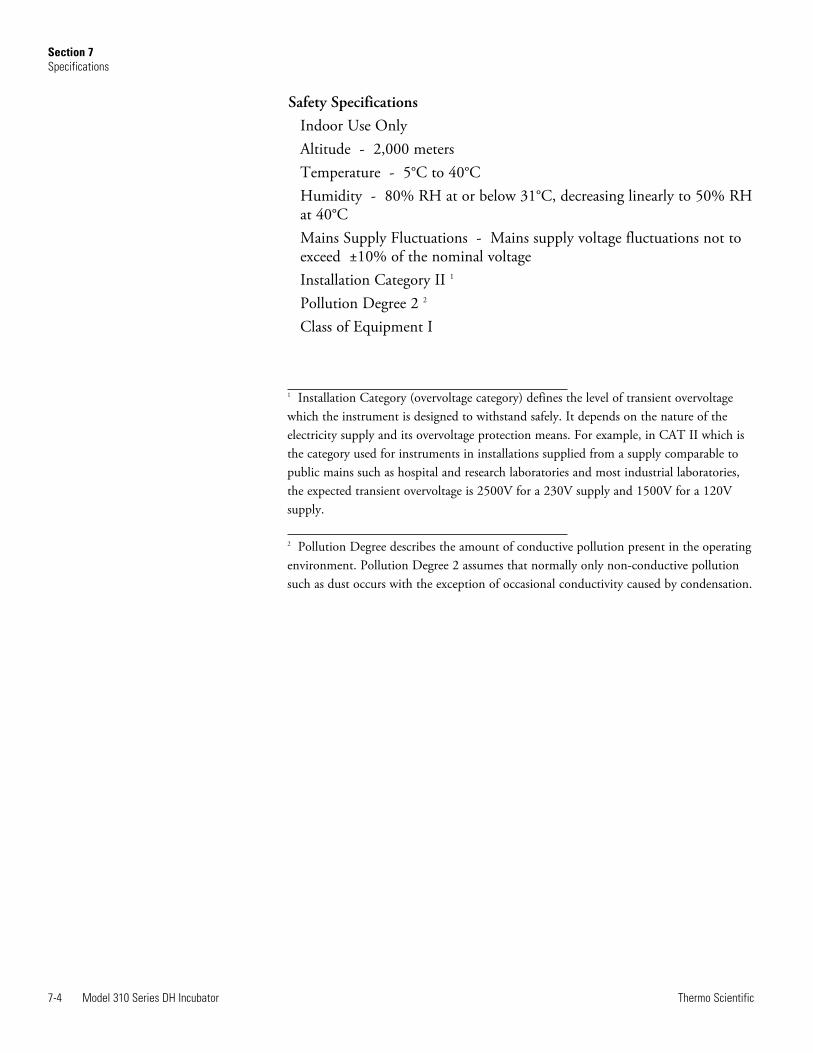
Safety SpecificationsIndoor Use OnlyAltitude - 2,000 metersTemperature - 5°C to 40°CHumidity - 80% RH at or below 31°C, decreasing linearly to 50% RHat 40°CMains Supply Fluctuations - Mains supply voltage fluctuations not toexceed ±10% of the nominal voltageInstallation Category II 1
Pollution Degree 2 2
Class of Equipment I
1 Installation Category (overvoltage category) defines the level of transient overvoltagewhich the instrument is designed to withstand safely. It depends on the nature of theelectricity supply and its overvoltage protection means. For example, in CAT II which isthe category used for instruments in installations supplied from a supply comparable topublic mains such as hospital and research laboratories and most industrial laboratories,the expected transient overvoltage is 2500V for a 230V supply and 1500V for a 120Vsupply.
2 Pollution Degree describes the amount of conductive pollution present in the operatingenvironment. Pollution Degree 2 assumes that normally only non-conductive pollutionsuch as dust occurs with the exception of occasional conductivity caused by condensation.
7-4 Model 310 Series DH Incubator Thermo Scientific
Section 7Specifications
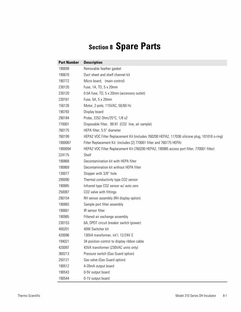
Section 8 Spare Parts
Model 310 Series DH Incubator 8-1Thermo Scientific
Part Number Description
190699 Removable feather gasket
190670 Duct sheet and shelf channel kit
190772 Micro board, (main control)
230135 Fuse, 1A, TD, 5 x 20mm
230120 0.5A fuse, TD, 5 x 20mm (accessory outlet)
230161 Fuse, 5A, 5 x 20mm
156126 Motor, 2-pole, 115VAC, 50/60 Hz
190793 Display board
290184 Probe, 2252 Ohm/25°C, 1/8 x2
770001 Disposable filter, 99.97 (CO2 line, air sample)
760175 HEPA filter, 5.5” diameter
760199 HEPA2 VOC Filter Replacement Kit (includes 760200 HEPA2, 117036 silicone plug, 101018 o-ring)
1900067 Filter Replacement Kit (includes [2] 770001 filter and 760175 HEPA)
1900094 HEPA2 VOC Filter Replacement Kit (760200 HEPA2, 190985 access port filter, 770001 filter)
224175 Shelf
190868 Decontamination kit with HEPA filter
190869 Decontamination kit without HEPA filter
130077 Stopper with 3/8” hole
290090 Thermal conductivity type CO2 sensor
190885 Infrared type CO2 sensor w/ auto zero
250087 CO2 valve with fittings
290154 RH sensor assembly (RH display option)
190883 Sample port filter assembly
190661 IR sensor filter
190985 Filtered air exchange assembly
230153 6A, DPDT circuit breaker switch (power)
400201 40W Switcher kit
420096 130VA transformer, int’l, 12/24V S
194021 34 position control to display ribbon cable
420097 43VA transformer (230VAC units only)
360213 Pressure switch (Gas Guard option)
250121 Gas valve (Gas Guard option)
190512 4-20mA output board
190543 0-5V output board
190544 0-1V output board
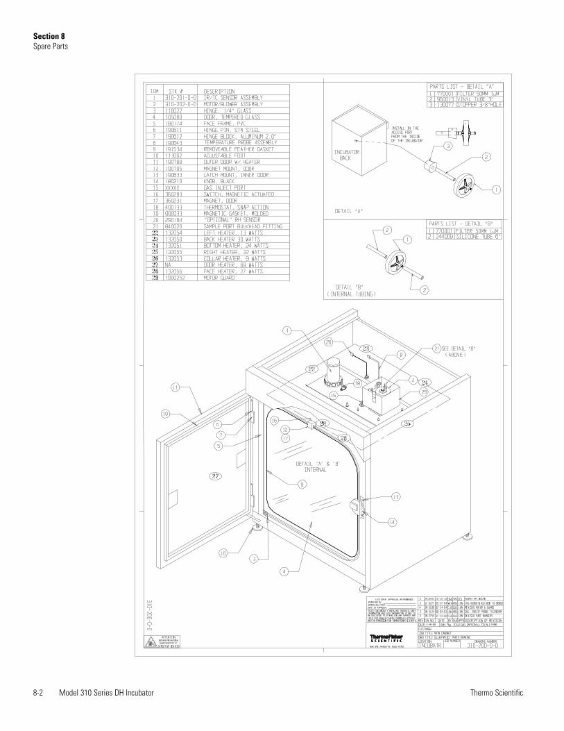
8-2 Model 310 Series DH Incubator Thermo Scientific
Section 8Spare Parts
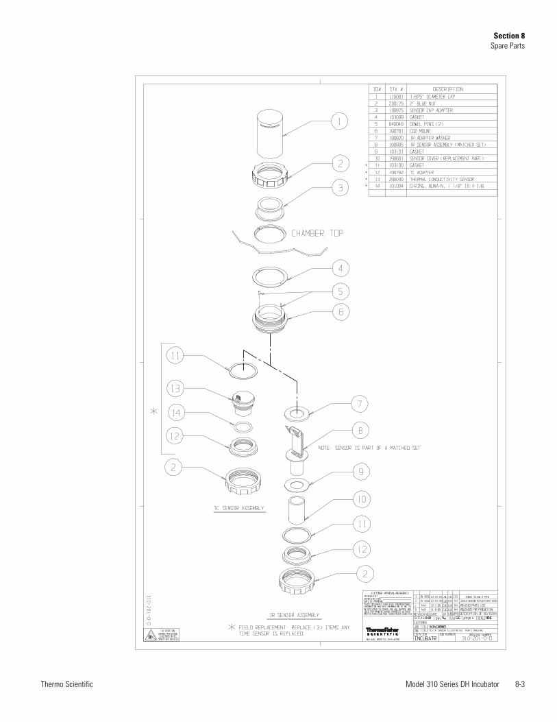
Model 310 Series DH Incubator 8-3Thermo Scientific
Section 8Spare Parts
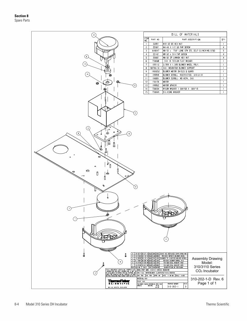
8-4 Model 310 Series DH Incubator Thermo Scientific
Section 8Spare Parts
Assembly DrawingModel:
310/3110 SeriesCO Incubator
310-202-1-D Rev. 6Page 1 of 1
2
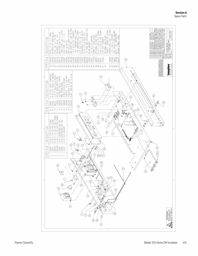
Model 310 Series DH Incubator 8-5Thermo Scientific
Section 8Spare Parts

8-6 Model 310 Series DH Incubator Thermo Scientific
Section 8Spare Parts
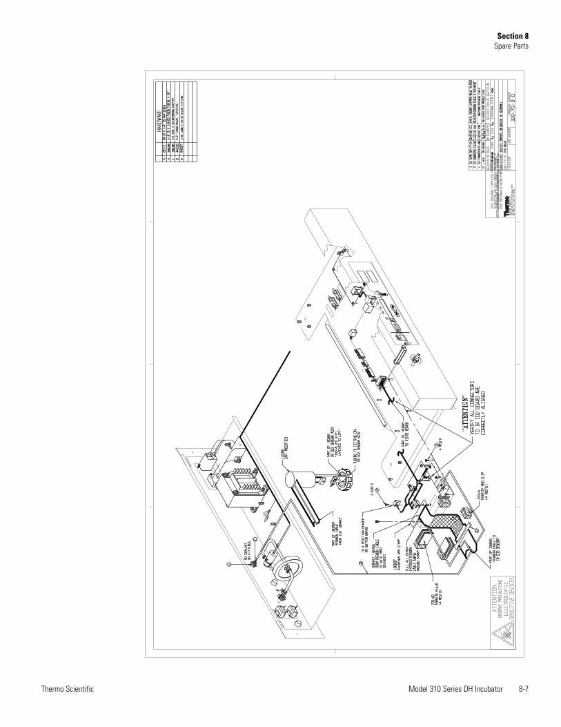
Model 310 Series DH Incubator 8-7Thermo Scientific
Section 8Spare Parts

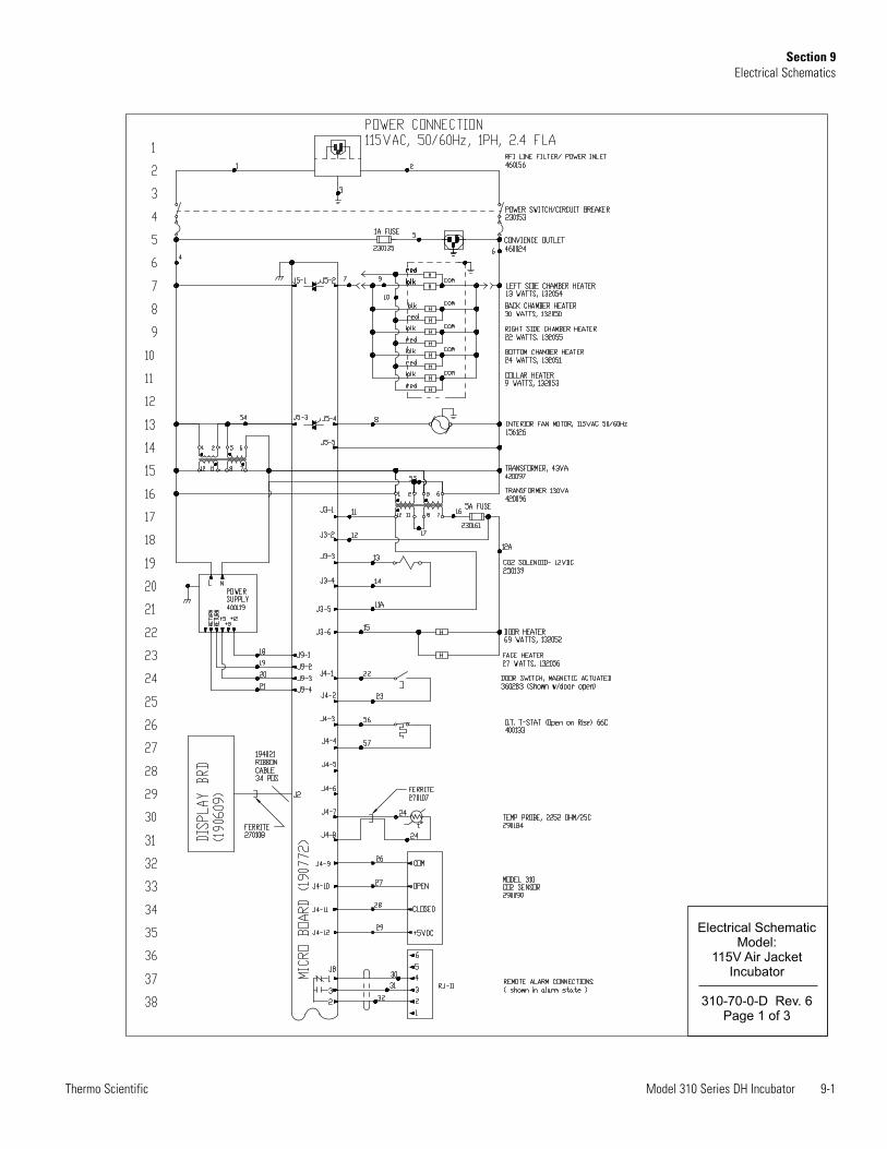
Model 310 Series DH Incubator 9-1Thermo Scientific
Section 9Electrical Schematics
Electrical SchematicModel:
115V Air JacketIncubator
310-70-0-D Rev. 6Page 1 of 3
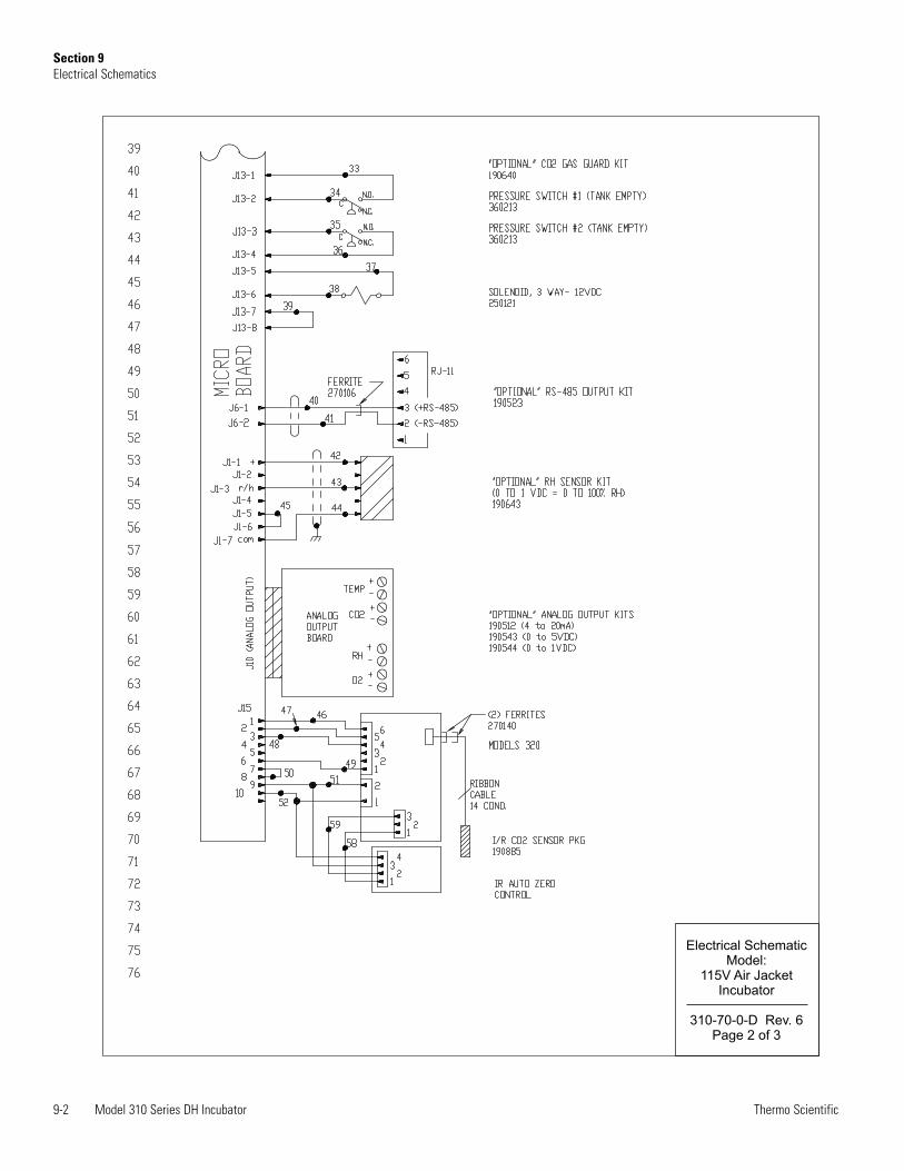
9-2 Model 310 Series DH Incubator Thermo Scientific
Section 9Electrical Schematics
Electrical SchematicModel:
115V Air JacketIncubator
310-70-0-D Rev. 6Page 2 of 3

Model 310 Series DH Incubator 9-3Thermo Scientific
Section 9Electrical Schematics
Electrical SchematicModel:
115V Air JacketIncubator
310-70-0-D Rev. 6Page 3 of 3
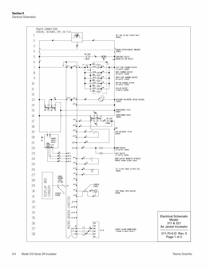
9-4 Model 310 Series DH Incubator Thermo Scientific
Electrical SchematicModel:
311 & 321Air Jacket Incubator
311-70-0-D Rev. 5Page 1 of 3
Section 9Electrical Schematics
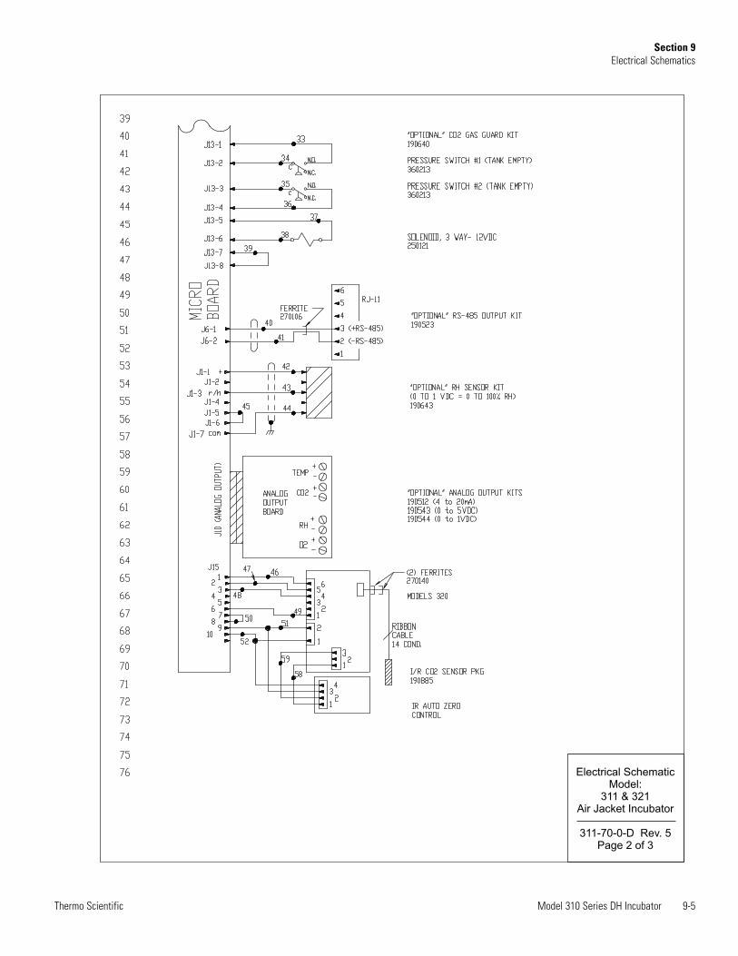
Model 310 Series DH Incubator 9-5Thermo Scientific
Section 9Electrical Schematics
Electrical SchematicModel:
311 & 321Air Jacket Incubator
311-70-0-D Rev. 5Page 2 of 3
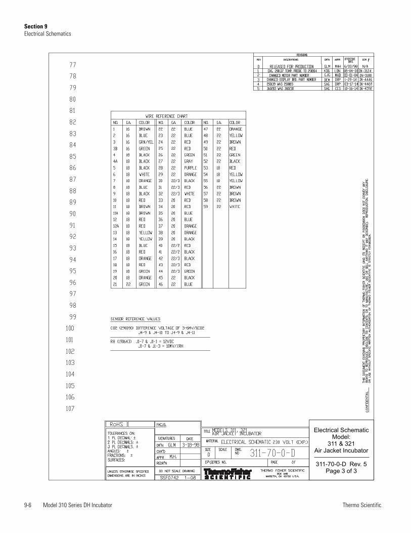
9-6 Model 310 Series DH Incubator Thermo Scientific
Section 9Electrical Schematics
Electrical SchematicModel:
311 & 321Air Jacket Incubator
311-70-0-D Rev. 5Page 3 of 3
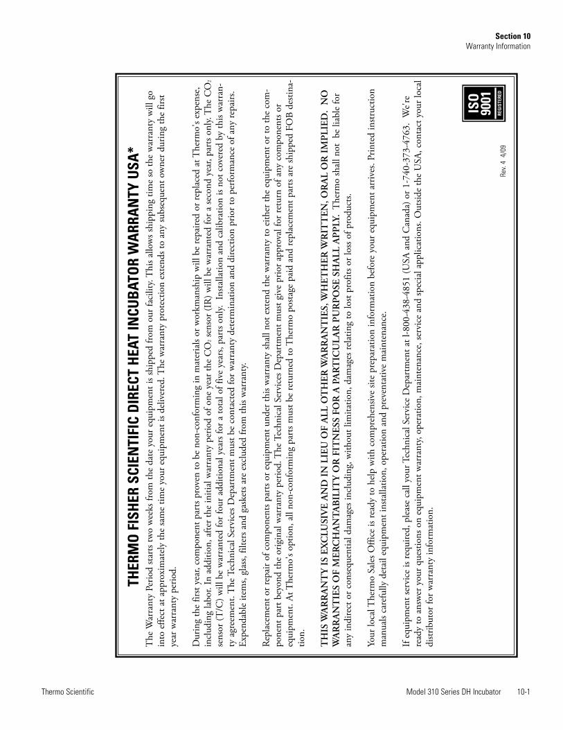
Model 310 Series DH Incubator 10-1Thermo Scientific
Section 10Warranty Information
THER
MO
FIS
HER
SCI
ENTI
FIC
DIR
ECT
HEA
T IN
CUB
ATO
R W
ARR
AN
TY U
SA*
The
War
rant
y Pe
riod
start
s tw
o w
eeks
from
the
date
you
r equ
ipm
ent i
s shi
pped
from
our
faci
lity.
Thi
s allo
ws s
hipp
ing
time
so th
e w
arra
nty
will
go
into
effe
ct a
t app
roxi
mat
ely
the
sam
e tim
e yo
ur e
quip
men
t is d
eliv
ered
. The
war
rant
y pr
otec
tion
exte
nds t
o an
y su
bseq
uent
ow
ner d
urin
g th
e fir
stye
ar w
arra
nty
perio
d.
Dur
ing
the
first
year
, com
pone
nt p
arts
prov
en to
be
non-
conf
orm
ing
in m
ater
ials
or w
orkm
ansh
ip w
ill b
e re
paire
d or
repl
aced
at T
herm
o's e
xpen
se,
incl
udin
g la
bor.
In a
dditi
on, a
fter t
he in
itial
war
rant
y pe
riod
of o
ne y
ear t
he C
O2
sens
or (I
R) w
ill b
e w
arra
nted
for a
seco
nd y
ear,
part
s onl
y. T
he C
O2
sens
or (T
/C) w
ill b
e w
arra
nted
for f
our a
dditi
onal
yea
rs fo
r a to
tal o
f fiv
e ye
ars,
part
s onl
y. In
stalla
tion
and
calib
ratio
n is
not c
over
ed b
y th
is w
arra
n-ty
agr
eem
ent.
The
Tec
hnic
al S
ervi
ces D
epar
tmen
t mus
t be
cont
acte
d fo
r war
rant
y de
term
inat
ion
and
dire
ctio
n pr
ior t
o pe
rform
ance
of a
ny re
pairs
.Ex
pend
able
item
s, gl
ass,
filte
rs a
nd g
aske
ts ar
e ex
clud
ed fr
om th
is w
arra
nty.
Repl
acem
ent o
r rep
air o
f com
pone
nts p
arts
or e
quip
men
t und
er th
is w
arra
nty
shal
l not
ext
end
the
war
rant
y to
eith
er th
e eq
uipm
ent o
r to
the
com
-po
nent
par
t bey
ond
the
orig
inal
war
rant
y pe
riod.
The
Tec
hnic
al S
ervi
ces D
epar
tmen
t mus
t giv
e pr
ior a
ppro
val f
or re
turn
of a
ny c
ompo
nent
s or
equi
pmen
t. At
The
rmo'
s opt
ion,
all
non-
conf
orm
ing
part
s mus
t be
retu
rned
to T
herm
o po
stage
pai
d an
d re
plac
emen
t par
ts ar
e sh
ippe
d FO
B de
stina
-tio
n.
TH
IS W
AR
RA
NT
Y I
S EX
CLU
SIV
E A
ND
IN
LIE
U O
F A
LL O
TH
ER W
AR
RA
NT
IES,
WH
ETH
ER W
RIT
TEN
, OR
AL
OR
IM
PLI
ED.
NO
WA
RR
AN
TIE
S O
F M
ERC
HA
NT
AB
ILIT
Y O
R F
ITN
ESS
FOR
A P
AR
TIC
ULA
R P
UR
PO
SE S
HA
LL A
PP
LY.
The
rmo
shal
l not
be
liabl
e fo
ran
y in
dire
ct o
r con
sequ
entia
l dam
ages
incl
udin
g, w
ithou
t lim
itatio
n, d
amag
es re
latin
g to
lost
prof
its o
r los
s of p
rodu
cts.
Your
loca
l The
rmo
Sale
s Offi
ce is
read
y to
hel
p w
ith c
ompr
ehen
sive
site
prep
arat
ion
info
rmat
ion
befo
re y
our e
quip
men
t arr
ives
. Prin
ted
instr
uctio
nm
anua
ls ca
refu
lly d
etai
l equ
ipm
ent i
nsta
llatio
n, o
pera
tion
and
prev
enta
tive
mai
nten
ance
.
If eq
uipm
ent s
ervi
ce is
requ
ired,
ple
ase
call
your
Tec
hnic
al S
ervi
ce D
epar
tmen
t at l
-800
-438
-485
1 (U
SA a
nd C
anad
a) o
r 1-7
40-3
73-4
763.
We'r
ere
ady
to a
nsw
er y
our q
uesti
ons o
n eq
uipm
ent w
arra
nty,
oper
atio
n, m
aint
enan
ce, s
ervi
ce a
nd sp
ecia
l app
licat
ions
. Out
side
the
USA
, con
tact
you
r loc
aldi
strib
utor
for w
arra
nty
info
rmat
ion.
ISO
9001
REG
ISTE
RED
Rev.
4 4
/09
10-2 Model 310 Series DH Incubator Thermo Scientific
Section 10Warranty Information
THER
MO
FIS
HER
SCI
ENTI
FIC
INTE
RNAT
ION
AL
DIR
ECT
HEA
T IN
CUB
ATO
R W
ARR
AN
TY*
The
War
rant
y Pe
riod
start
s tw
o m
onth
s fro
m th
e da
te y
our e
quip
men
t is s
hipp
ed fr
om o
ur fa
cilit
y. T
his a
llow
s shi
ppin
g tim
e so
the
war
rant
y w
ill g
oin
to e
ffect
at a
ppro
xim
atel
y th
e sa
me
time
your
equ
ipm
ent i
s del
iver
ed. T
he w
arra
nty
prot
ectio
n ex
tend
s to
any
subs
eque
nt o
wne
r dur
ing
the
first
year
war
rant
y pe
riod.
Dur
ing
the
first
year
com
pone
nt p
arts
prov
en to
be
non-
conf
orm
ing
in m
ater
ials
or w
orkm
ansh
ip w
ill b
e re
paire
d or
repl
aced
at T
herm
o's e
xpen
se,
exce
ptin
g la
bor.
In a
dditi
on, a
fter t
he in
itial
war
rant
y pe
riod
of o
ne y
ear t
he C
O2
sens
or (I
R) w
ill b
e w
arra
nted
for a
seco
nd y
ear,
part
s onl
y. T
heC
O2
sens
or (T
/C) w
ill b
e w
arra
nted
for f
our a
dditi
onal
yea
rs fo
r a to
tal o
f fiv
e ye
ars,
part
s onl
y. In
stalla
tion
and
calib
ratio
n is
not c
over
ed b
y th
isw
arra
nty
agre
emen
t. T
he T
echn
ical
Ser
vice
s Dep
artm
ent m
ust b
e co
ntac
ted
for w
arra
nty
dete
rmin
atio
n an
d di
rect
ion
prio
r to
perfo
rman
ce o
f any
repa
irs. E
xpen
dabl
e ite
ms,
glas
s, fil
ters
and
gas
kets
are
excl
uded
from
this
war
rant
y.
Repl
acem
ent o
r rep
air o
f com
pone
nts p
arts
or e
quip
men
t und
er th
is w
arra
nty
shal
l not
ext
end
the
war
rant
y to
eith
er th
e eq
uipm
ent o
r to
the
com
-po
nent
par
t bey
ond
the
orig
inal
war
rant
y pe
riod.
The
Tec
hnic
al S
ervi
ces D
epar
tmen
t mus
t giv
e pr
ior a
ppro
val f
or re
turn
of a
ny c
ompo
nent
s or
equi
pmen
t. At
The
rmo'
s opt
ion,
all
non-
conf
orm
ing
part
s mus
t be
retu
rned
to T
herm
o po
stage
pai
d an
d re
plac
emen
t par
ts ar
e sh
ippe
d FO
B de
stina
-tio
n.
TH
IS W
AR
RA
NT
Y I
S EX
CLU
SIV
E A
ND
IN
LIE
U O
F A
LL O
TH
ER W
AR
RA
NT
IES,
WH
ETH
ER W
RIT
TEN
, OR
AL
OR
IM
PLI
ED. N
OW
AR
RA
NT
IES
OF
MER
CH
AN
TA
BIL
ITY
OR
FIT
NES
S FO
R A
PA
RT
ICU
LAR
PU
RP
OSE
SH
ALL
AP
PLY
.The
rmo
shal
l not
be
liabl
e fo
ran
y in
dire
ct o
r con
sequ
entia
l dam
ages
incl
udin
g, w
ithou
t lim
itatio
n, d
amag
es re
latin
g to
lost
prof
its o
r los
s of p
rodu
cts.
Your
loca
l The
rmo
Sale
s Offi
ce is
read
y to
hel
p w
ith c
ompr
ehen
sive
site
prep
arat
ion
info
rmat
ion
befo
re y
our e
quip
men
t arr
ives
. Prin
ted
instr
uctio
nm
anua
ls ca
refu
lly d
etai
l equ
ipm
ent i
nsta
llatio
n, o
pera
tion
and
prev
entiv
e m
aint
enan
ce.
If eq
uipm
ent s
ervi
ce i
s req
uire
d, p
leas
e ca
ll yo
ur T
echn
ical
Ser
vice
s Dep
artm
ent a
t 1-8
00-4
38-4
851
(USA
and
Can
ada)
or 1
-740
-373
-476
3. W
e're
read
y to
ans
wer
you
r que
stion
s on
equi
pmen
t war
rant
y, op
erat
ion,
mai
nten
ance
, ser
vice
and
spec
ial a
pplic
atio
n. O
utsid
e th
e U
SA, c
onta
ct y
our l
ocal
distr
ibut
or fo
r war
rant
y in
form
atio
n.
ISO
9001
REG
ISTE
RED
Rev.
4 4
/09

Thermo Fisher Scientific401 Millcreek RoadMarietta, Ohio 45750United States
www.thermofisher.com


![User Manual - Forma - 3029, 3039 - Countertop Incubator 10 Cu.ft. - 7013029[1] Copy](https://static.fdocuments.in/doc/165x107/577c7fbb1a28abe054a5d1d6/user-manual-forma-3029-3039-countertop-incubator-10-cuft-70130291.jpg)


![Manual for TC CO2 Incubator[1]](https://static.fdocuments.in/doc/165x107/54e80c294a7959d76d8b4a7f/manual-for-tc-co2-incubator1.jpg)