Form P-PREEVA (Version E) Obsoletes Form P-PREEVA … P-PREEVA (Version E) Obsoletes Form P-PREEVA...
44
P-PREEVA, Page � Form P-PREEVA (Version E) Obsoletes Form P-PREEVA (Version D) Replacement Parts Applies to: PREEVA ® Indoor Model PDH, Model SDH, Model PEH, and Model PXH and Outdoor Model RDH, Model REH, and Model RXH Pre-Engineered Ventilation Air Handlers and High Efficiency Indoor Model SHH IMPORTANT 1. Always include complete heater model and serial number so that any specification change can be considered for parts replacement. It can save time and expense. 2. In keeping with our policy of continuous product improve- ment, we reserve the right to alter any information shown here. Specifications are subject to change without notice. 3. We reserve the right to substitute functional replacements 4. Order by P/N; not Heater Option Designation. RDH, Gas-fired Heat, Power-Vented (with outside air hood attached) A Air Proving Switch 3 AquaSaver Timed Controls 42 B Ball Joint 28 Bearings 20 Belts 21 Bleed Line Hose 42 Blowers 20 Burner Assembly 19 C Cabinet Doors 34 Cabinet Parts - Cooling Coil Module 23 Cabinet Parts - Indoor Model PDH 36 Cabinet Parts - Indoor Model PEH 38 Cabinet Parts - Indoor Model SDH 37 Cabinet Parts - Indoor Model SHH 40 Cabinet Parts - Mixing Box 29 Cabinet Parts - Outdoor Model RDH 34 Cabinet Parts - Outdoor Model REH 39 Cabinet Parts - Evaporative Cooling Module 44 Capacitor 16, 26 Reheat Compressor 26 Contactor 7, 12 Convenience Outlet 10 Crankcase Heater 26 Curb Adapter 33 D Mixing Box Damper Controls 28 Damper Arm 28 Damper Assy (Option AR8) 27 Damper Motor 27 Damper Rod 28 Dampers 28, 29 Dehumidistat, Option CL47 11 Digital Controller FX05 for Opt DG 6 Digital Controller FX06 for D12 B, C, F 6 Digital Controller FX06 with D12 D and E 7 Dirty Filter Switch 3 Discharge Air Sensor 6 Discharge Plenum 31 Distribution Block 7 Door 29, 31 Door Latch 29, 31, 34 Door Switch 10 Downturn Plenum 31 Drive Components 21 DSI (Direct Spark Ignition) Control Board 3 Duct Flange 27, 31 Ductstat 5, 10, 11 Ductstat Stage Adder 10 E Economizer Logic Module 28, 29 Electrical Component Locations 3 Electric Heating Element 7 Electric Heating Element Limit Control 7 Electric Heat Section Electrical Compartment 6 Electrode 19 Enthalpy Sensor 28 Evaporative Cooling Media Pads 41 Evaporative Cooling Module 41 F Feed Line 44 Fill and Drain Kits 43 Electronic Filter 5 Filter Drier 26 Filters 27 Firestat 10 Flame Sensor 19 Float Switch 42 Float Valve 42 Freeze Protection Controls 43 Freezestat 5 Frostat 25, 26 Fuse 3, 7 G Gas Conversion Kits 19 Gas Pressure Switch 5 Gas Train 19 Gas Valve 5 H Heat Exchanger 18 High Ambient Limit Control 10 Hinge 34 Inlet Air Hood (Option AS2) 27 Horizontal Vent/Combustion Air Terminal Kit (Same as Option CC6) 17 Rubber Hose 42 I Inlet Screen 27 L Label 34 High Temperature Auto Reset Limit 3 Reverse Flow Limit Switch 10 Louvers 31, 32 M Media Pads 41 Microprocessor Timer 42 Damper Motor 28 Discharge Damper Motor 31 Motor Base 20 Blower Motors 12, 15 N Nozzles 31, 32 O Gas Orifice 19 Orifice Adapter Bushing 19 Outside Air Relative Humidity Transmitter, Op- tion DT5 11 Overloads 12 P Paint 34 Phase Loss Control 3 Plug-in Cards 6 Potentiometer 28 Pre-Filters (Option PF4 and PF5) 41 Combustion Air Pressure Switch 3, 4 Pulleys 21 Pump 42 Pump and Float Control 42 Pump Support 42 R Rating Plate 2 DX Cooling Cabinet with Reheat 26 Reheat Condenser Coil 26 Reheat Evaporator Coil 26 Relay 3, 4, 7, 43 Time Delay Relay 5 Remote Console 12 Remote User Interface 11 Primary Air Restrictor 19 Return Air Controller 28 Reverse Flow Limit Switch 10 Roof Curb 32 Room Command Module 11 S Intake Screen 44 SCR Power Controller 7 Sensing Tube Assembly 20 Sensor 11 Sensor Mixing Tube Holder 6 Serial No. 2 Service Switch 10 Damper Motor Connecting Shaft 28 Shaft (Blower) 20 Signal Conditioner 5 Smoke Detector 10, 11 2-Way Solenoid Valve 43 3-Way Solenoid Valve 43 Space Air Sensor, Option CL53 11 Spring Isolation 20 Sprinkler Pipe 44 Starters 12 Step Controller 7 Disconnect Switch 12 Pressure Null Switch 28 Pressure Switch 26 2-position Switch 10 T Static Pressure Tap 16 Temperature Controller 43 Terminal Block 42 Terminal Board for Thermostat 3 Thermostatic Expansion Valve for Reheat 26 Thermostats 11 Transformer 3, 4, 7, 16, 42 U Ultra-Violet, Germicidal Light 26 V Ball Valve 42 Variable Frequency Drive 3, 4 Vent/Combustion Air Kits - SDH & SHH 17 Vent Cap 17 Venter Components 16 Venter Housing 16 Venter Motor 16 Venter Motor and Wheel Assembly 16 Venter Motor Capacitor 16 Venter Speed Controller 5 Vertical Vent - Model RDH 17 Vertical Vent/Combustion Air Terminal Kit (Same as Option CC2) 17 W Water Hammer Arrestor 42 Wheel 16 INDEX References Download Forms at www.RezSpec.com ................................................................................ Form ........................... P/N Outdoor Installation Manual (Models RDH, REH, and RXH)............................................. I-RDH/REH/RXH................ 215210 Indoor Installation Manual (Models PDH, SDH, SHH, PEH, and PXH) ..................... I-PDH/SDH/PEH/SHH/PXH ....... 211408 Venting Manual - Model PDH ................................................................................................... I-PDH-V....................... 211409 Venting Manual - Model SDH ................................................................................................... I-SDH-V....................... 211410 Venting Manual - Model SHH ................................................................................................... I-SHH-V....................... 257037 PREEVA Operation Manual - All PREEVA Models and SHH........................................... O-PREEVA & SHH .............. 234661 Digital Control Instructions - Option DG1, DG2, DG5, DG6 ............................................. CP-PREEVA-DG................ 254027 Digital Control Instructions - Option D12B, D12C, D12D, D12E, or D12F ................. CP-PREEVA-D12B/C/D/E ........ 235267 Gas Conversion - Models RDH, PDH, SDH with 1 or 2 stage gas control ........................ CP-PREEVA-GC................ 212063 Model MASA Condensing Unit Installation Manual .................................................................. I-COND....................... 220746 Model MASA Condensing Unit Parts ........................................................................................P-COND Indoor Models SDH, Gas-Fired Heat, Separated Combustion PDH, Gas-Fired Heat, Power Vent PEH, Electric Heat PXH*, Air Handler Outdoor Models REH, Electric Heat RXH*, Air Handler *Air handler (no heat); similar in appearance to the electric model SHH, Gas-Fired Heat, High Efficiency, Separated Combustion
Transcript of Form P-PREEVA (Version E) Obsoletes Form P-PREEVA … P-PREEVA (Version E) Obsoletes Form P-PREEVA...

P-PREEVA, Page �
�Form P-PREEVA (Version E)
Obsoletes Form P-PREEVA (Version D)
Replacement Parts
Applies to: PREEVA® Indoor Model PDH, Model SDH, Model PEH, and Model PXH and
Outdoor Model RDH, Model REH, and Model RXH Pre-Engineered Ventilation Air Handlers
and High Efficiency Indoor Model SHH
IMPORTANT1. Always include complete heater model and serial number so
that any specification change can be considered for parts replacement. It can save time and expense.
2. In keeping with our policy of continuous product improve-ment, we reserve the right to alter any information shown here. Specifications are subject to change without notice.
3. We reserve the right to substitute functional replacements4. Order by P/N; not Heater Option Designation.
RDH, Gas-fired Heat, Power-Vented (with outside
air hood attached)
AAir Proving Switch 3AquaSaver Timed Controls 42
BBall Joint 28Bearings 20Belts 21Bleed Line Hose 42Blowers 20Burner Assembly 19
CCabinet Doors 34Cabinet Parts - Cooling Coil Module 23Cabinet Parts - Indoor Model PDH 36Cabinet Parts - Indoor Model PEH 38Cabinet Parts - Indoor Model SDH 37Cabinet Parts - Indoor Model SHH 40Cabinet Parts - Mixing Box 29Cabinet Parts - Outdoor Model RDH 34Cabinet Parts - Outdoor Model REH 39Cabinet Parts - Evaporative Cooling Module 44Capacitor 16, 26Reheat Compressor 26Contactor 7, 12Convenience Outlet 10Crankcase Heater 26Curb Adapter 33
DMixing Box Damper Controls 28Damper Arm 28Damper Assy (Option AR8) 27Damper Motor 27Damper Rod 28Dampers 28, 29Dehumidistat, Option CL47 11Digital Controller FX05 for Opt DG 6Digital Controller FX06 for D12 B, C, F 6Digital Controller FX06 with D12 D and E 7Dirty Filter Switch 3Discharge Air Sensor 6Discharge Plenum 31Distribution Block 7Door 29, 31Door Latch 29, 31, 34Door Switch 10Downturn Plenum 31Drive Components 21DSI (Direct Spark Ignition) Control Board 3Duct Flange 27, 31Ductstat 5, 10, 11Ductstat Stage Adder 10
EEconomizer Logic Module 28, 29Electrical Component Locations 3Electric Heating Element 7Electric Heating Element Limit Control 7Electric Heat Section Electrical Compartment 6Electrode 19Enthalpy Sensor 28Evaporative Cooling Media Pads 41Evaporative Cooling Module 41
FFeed Line 44
Fill and Drain Kits 43Electronic Filter 5Filter Drier 26Filters 27Firestat 10Flame Sensor 19Float Switch 42Float Valve 42Freeze Protection Controls 43Freezestat 5Frostat 25, 26Fuse 3, 7
GGas Conversion Kits 19Gas Pressure Switch 5Gas Train 19Gas Valve 5
HHeat Exchanger 18High Ambient Limit Control 10Hinge 34Inlet Air Hood (Option AS2) 27Horizontal Vent/Combustion Air Terminal Kit
(Same as Option CC6) 17Rubber Hose 42
IInlet Screen 27
LLabel 34High Temperature Auto Reset Limit 3Reverse Flow Limit Switch 10Louvers 31, 32
MMedia Pads 41Microprocessor Timer 42Damper Motor 28Discharge Damper Motor 31Motor Base 20Blower Motors 12, 15
NNozzles 31, 32
OGas Orifice 19Orifice Adapter Bushing 19Outside Air Relative Humidity Transmitter, Op-
tion DT5 11Overloads 12
PPaint 34Phase Loss Control 3Plug-in Cards 6Potentiometer 28Pre-Filters (Option PF4 and PF5) 41Combustion Air Pressure Switch 3, 4Pulleys 21Pump 42Pump and Float Control 42Pump Support 42
RRating Plate 2DX Cooling Cabinet with Reheat 26
Reheat Condenser Coil 26Reheat Evaporator Coil 26Relay 3, 4, 7, 43Time Delay Relay 5Remote Console 12Remote User Interface 11Primary Air Restrictor 19Return Air Controller 28Reverse Flow Limit Switch 10Roof Curb 32Room Command Module 11
SIntake Screen 44SCR Power Controller 7Sensing Tube Assembly 20Sensor 11Sensor Mixing Tube Holder 6Serial No. 2Service Switch 10Damper Motor Connecting Shaft 28Shaft (Blower) 20Signal Conditioner 5Smoke Detector 10, 112-Way Solenoid Valve 433-Way Solenoid Valve 43Space Air Sensor, Option CL53 11Spring Isolation 20Sprinkler Pipe 44Starters 12Step Controller 7Disconnect Switch 12Pressure Null Switch 28Pressure Switch 262-position Switch 10
TStatic Pressure Tap 16Temperature Controller 43Terminal Block 42Terminal Board for Thermostat 3Thermostatic Expansion Valve for Reheat 26Thermostats 11Transformer 3, 4, 7, 16, 42
UUltra-Violet, Germicidal Light 26
VBall Valve 42Variable Frequency Drive 3, 4Vent/Combustion Air Kits - SDH & SHH 17Vent Cap 17Venter Components 16Venter Housing 16Venter Motor 16Venter Motor and Wheel Assembly 16Venter Motor Capacitor 16Venter Speed Controller 5Vertical Vent - Model RDH 17Vertical Vent/Combustion Air Terminal Kit (Same
as Option CC2) 17
WWater Hammer Arrestor 42Wheel 16
INDEX
References
Download Forms at www.RezSpec.com ................................................................................ Form ........................... P/NOutdoor Installation Manual (Models RDH, REH, and RXH) ............................................. I-RDH/REH/RXH ................ 215210Indoor Installation Manual (Models PDH, SDH, SHH, PEH, and PXH) ..................... I-PDH/SDH/PEH/SHH/PXH ....... 211408Venting Manual - Model PDH ................................................................................................... I-PDH-V ....................... 211409Venting Manual - Model SDH ................................................................................................... I-SDH-V ....................... 211410Venting Manual - Model SHH ................................................................................................... I-SHH-V ....................... 257037PREEVA Operation Manual - All PREEVA Models and SHH ........................................... O-PREEVA & SHH .............. 234661Digital Control Instructions - Option DG1, DG2, DG5, DG6 ............................................. CP-PREEVA-DG ................ 254027Digital Control Instructions - Option D12B, D12C, D12D, D12E, or D12F .................CP-PREEVA-D12B/C/D/E ........ 235267Gas Conversion - Models RDH, PDH, SDH with 1 or 2 stage gas control ........................ CP-PREEVA-GC ................ 212063Model MASA Condensing Unit Installation Manual .................................................................. I-COND ....................... 220746Model MASA Condensing Unit Parts ........................................................................................P-COND
Indoor Models
SDH, Gas-Fired Heat, Separated Combustion
PDH, Gas-Fired Heat, Power Vent
PEH, Electric HeatPXH*, Air Handler
Outdoor Models
REH, Electric HeatRXH*, Air Handler
*Air handler (no heat); similar in appearance to the electric model
SHH, Gas-Fired Heat, High Efficiency, Separated
Combustion
P-PREEVA, Page �
Serial No. Date of Manufacture Codes (all Models)
Sample of Gas-Fired Model Heat Section Rating Plate and Key
A = ANSI Standard DateA� = CSA Standard DateB = Model No.C = Date of Manufacture (Month/Year)D = Blower Motor HP (Option)E = Input Amps F = Fuel Type (natural gas or propane)G = Normal Manifold PressureH = Minimum Gas Supply PressureI = Altitude (Feet)I� = Altitude (Meters)
Year Jan Feb Mar Apr May June July Aug Sept Oct Nov Dec�005 BEA BEB BEC BED BEE BEF BEG BEH BEI BEJ BEK BEL
�006 BFA BFB BFC BFD BFE BFF BFG BFH BFI BFJ BFK BFL
�007 BGA BGB BGC BGD BGE BGF BGG BGH BGI BGJ BGK BGL
�008 BHA BHB BHC BHD BHE BHF BHG BHH BHI BHJ BHK BHL
�009 BIA BIB BIC BID BIE BIF BIG BIH BII BIJ BIK BIL
�0�0 BJA BJB BJC BJD BJE BJF BJG BJH BJI BJJ BJK BJL
�0�� BKA BKB BKC BKD BKE BKF BKG BKH BKI BKJ BKK BKL
�0�� BLA BLB BLC BLD BLE BLF BLG BLH BLI BLJ BLK BLL
�0�3 BMA BMB BMC BMD BME BMF BMG BMH BMI BMJ BMK BML
�0�4 BNA BNB BNC BND BNE BNF BNG BNH BNI BNJ BNK BNL
�0�5 BOA BOB BOC BOD BOE BOF BOG BOH BOI BOJ BOK BOL
�0�6 BPA BPB BPC BPD BPE BPF BPG BPH BPI BPJ BPK BPL
�0�7 BQA BQB BQC BQD BQE BQF BQG BQH BQI BQJ BQK BQL
�0�8 BRA BRB BRC BRD BRE BRF BRG BRH BRI BRJ BRK BRL
�0�9 BSA BSB BSC BSD BSE BSF BSG BSH BSI BSJ BSK BSL
�0�0 BTA BTB BTC BTD BTE BTF BTG BTH BTI BTJ BTK BTL
Serial No. and Rating PlateSerial No. Decoding - Models SDH/PDH/SHH/RDHSerial No. Sample: BHD 78 Y8 N 00000Element Key No.: 1 | 2 | 3 |4| 5Key: � = Date of Manufacture (See table right.) � = Ignition Code (78 for Item 18 DSI control on page 4 or See Form P-Valves to identify) 3 = Valve Code (See Form P-Valves to identify code.) 4 = Type of Heat Energy (N = Natural Gas; L = Propane) 5 = Consecutive number
REZNORMERCER, PA. USA 16137
SEPARATED COMBUSTION SYSTEM UNIT HEATERFOR INDUSTRIAL/COMMERCIAL USECATEGORY [ S ]ANSI Z83.8 [ A ] CSA 2.6 [ A’ ] UNIT HEATERMODEL [ B ] [ C ]SERIAL NO. [ D ] HP[ E ] VOLTS [ E ] PH [ E ] HZ MAXIMUM TOTAL INPUT [ E ] AMPS
TYPE OF GAS: [ F ]FOR USE AT [ I ] FEET, [ I’ ] METERS OF ALTITUDE.ORIFICE SIZE [ L ] DRILL
SEA LEVEL ALT. ADJUSTED
NORMAL INPUT [ N ] [ X ] BTU/HR
THERMAL OUTPUT CAPACITY [ P ] [ Y ] BTU/HR
MINIMUM INPUT (2,2L,D2,DM,D2J,DMJ MODELS) [ Q ] [ Z ] BTU/HR
NORMAL MANIFOLD PRESSURE [ G ] [ AA ] IN. W.C.
MIN. PERMISSIBLE GAS SUPPLY PRESSURE
FOR PURPOSE OF INPUT ADJUSTMENT. [ H ] IN.
TEMPERATURE RISE RANGE FROM [ J ] DEG. F. TO [ K ] DEG. F.
MAXIMUM EXTERNAL STATIC PRESSURE [ M ] IN. W.C.
EQUIPPED FOR OPERATION AT AN AIR FLOW OF [ T ] SCFM
AGAINST A STATIC PRESSURE OF [ U ] IN. W.C.
DRIVE NO. [ V ] WIRING DIAGRAM [ W ]
CLEARANCES TO COMBUSTIBLE CONSTRUCTION: TOP-18”, FLUE
CONNECTION-18”, CONTROL SIDE-[ R ]”, OPP. SIDE-18”, BOTTOM-0”, FRONT-48”
FOR ALTERNATE INSTALLATIONS USE THE LATEST EDITIONS OF THE
APPROPRIATE STANDARD LISTED BELOW:
FOR AIRCRAFT HANGARS USE STANDARD ANSI/NFPA 409
FOR PARKING STRUCTURES USE STANDARD ANSI/NFPA 88A
FOR REPAIR GARAGES USE STANDARD ANSI/NFPA 88B
INSTALLATION OF THIS UNIT IN AIRCRAFT HANGERS IN ACCORDANCE WITH THE
REQUIREMENTS OF THE ENFORCING AUTHORITIES AND IN PUBLIC GARAGES IN
ACCORDANCE WITH THE CAN/CSA-B149 CODES.
THIS UNIT MAY BE INSTALLED DOWNSTREAM FROM A REFRIGERATION SYSTEM.
THIS UNIT MAY BE USED WITH DUCTS AND FILTERS.
CONSTRUCTION WALL THICKNESS FOR PURPOSE OF VENTING: 1” MIN., 48” MAX.
Prefix to Gas-Fired Model Serial No. Prefix Key: E = E3 (409) Stainless Steel Heat Exchanger S = 316 Stainless Steel Heat Exchanger
Serial No. Decoding - Models PEH/REHSerial No. Sample: BHD D��D E 00000Element Key No.: 1 | 2 |3| 4Key: � = Date of Manufacture (See table right.) � = Ignition Code (D12D, D12E, EG1M, EG2M) 3 = Type of Heat Energy (E = Electric) 4 = Consecutive number
REZNOR MERCER, PA. USA 16137
MADE IN USAUNIT HEATER FOR INDUSTRIAL/COMMERCIAL USEMODEL [ A ] [ B ]
SERIAL NO. [ C ] VOLTS +/- 10% [ C ] PH [ C ] HZ
MINIMUM CIRCUIT AMPACITY (MCA) [ D ] AMPS
MAXIMUM FUSE SIZE/*CKT BREAKER [ E ] AMPS
*HACR TYPE REQUIRED PER NEC
NORMAL INPUT [ F ] KW
QTY FLA HP
SUPPLY AIR BLOWER MOTOR � [ G ] [ H ]TEMPERATURE RISE RANGE FROM 20 DEG. F. TO 75 DEG. F.
MAXIMUM EXTERNAL STATIC PRESSURE 3.0 IN. W.C.
EQUIPPED FOR OPERATION AT AN AIR FLOW OF [ I ] SCFM
AGAINST A STATIC PRESSURE OF [ J ] IN. W.C.
DRIVE NO. [ K ] WIRING DIAGRAM [ L ]CLEARANCES TO COMBUSTIBLE CONSTRUCTION: TOP-6", CONTROL SIDE-20", OPP. SIDE-6", BOTTOM-0"
QTY RLA (EA) LRA
COMPRESSOR � [ N ] [ O ]
REFRIGERANT - R-4�0A CHARGE - [ P ] LBS
TEST PRESSURES - HIGH 600 PSIG, LOW 112 PSIG
Sample of Electric Model Rating Plate with Optional Reheat
A = Model No.B = Date of Manufacture (Month/Year)C = Supply Voltage D = MCAE = Maximum Fuse SizeF = KWG = Blower Motor FLAH = Blower Motor HP I = SCFMJ = Static PressureK = Drive Option Designation (AM__)L = Wiring Diagram No. N = AU7 Compressor RLAO = AU7 Compressor LRAP = Compressor Refrigerant Charge
REZNORMERCER, PA., U.S.A. 16137
MADE IN USA
UNIT HEATER FOR INDUSTRIAL/COMMERCIAL USEMODEL [ B ]SERIAL NO. [ ]
ELECTRICAL[ E ] VOLTS +/- 10% [ E ] PHASE [ E ] HZ
MINIMUM CIRCUIT AMPACITY (MCA) [ AH ] AMPS
MAXIMUM FUSE SIZE/*CKT BREAKER [ AI ] AMPS
FUSIBLE MAX./DISJONCTEUR MAX. [ AI ] AMPS
QTY FLA (EA) HP (EA)
SUPPLY AIR BLOWER MOTOR � [ AJ ] [ D ]QTY RLA (EA) LRA (EA)
COMPRESSOR A [ AD ] [ AE ] [ AF ]CIRCUITS A
REFRIGERANT - R-4�0a CHARGE - LBS [ AG ]TEST PRESSURES HIGH 600PSIG LOW ���PSIGREFER TO RATING PLATE IN THE FURNACE SECTION (WHEN USED) FOR ADDITIONAL INFORMATION.*HACR TYPE REQUIRED PER NEC
J = Minimum Temperature Rise (°F)K = Maximum Temperature Rise (°F)L = Orifice SizeM = Maximum External StaticN = Normal BTUH Input (sea level)P = Thermal Output BTUH (sea level)Q = Minimum BTUH Input (sea level)R = Control Side Clearance (inches)S = CategoryT = SCFMU = Static PressureV = Drive Option Designation (AM__)W = Wiring Diagram No.X = Normal BTUH Input (adjusted for alti-
tude)Y = Thermal Output BTUH (adjusted for
altitude)Z = Minimum BTUH Input (adjusted for
altitude)AA = Normal Manifold Pressure (inches w.c.
adjusted for altitude)
Sample of Optional Reheat Rating Plate on Gas-Fired Model and Key
B = Model No.D = Blower Motor HP (Option)E = Input AmpsAD = Compressor QuantityAE = Compressor RLA
AF = Compressor LRA AG = Compressor Refrigerant ChargeAH = MCAAI = Maximum Fuse SizeAJ = Blower Motor FLA

P-PREEVA, Page 3
Electrical Component Locations and P/N’s
Code Description
PDH/SDH/RDH Sizes 75 �00 ��5 �50 �75 �00 ��5 �50 300 350 400APXH/RXH Sizes 000A 000B 000C 000D 000E
SHH Sizes N/A N/A �30C �80C �60D 350EPEH/REH Sizes 10A/20A/40A 15B/30B/60B N/A 30D/60D/90D/120D 40E/80E/120E
In the Left Electrical Compartment (high voltage & low voltage) - parts apply to all Models or with options as listed:�A Phase Loss Control (Option BF15) �06�05, ICM 401�B Phase Loss & Over/Under Voltage Cntrl (Opt BF14) �768�6, 201A� Plug-in Relays - See P/N's and illustration on page 4.
3Transformer (for optional evaporative cooling module; either located at CODE 3 or in the cooling module control box as listed)
115V/1ph �94808, 40 VA208-230V/1ph & 208/3ph �94536, 40 VA (located in the cooling module control box)230V/3ph �94536, 40 VA460V �0�66�, 40 VA575V �05�0�, 275VA (plus P/N �94808, 115/24V, 40VA in the cooling module box)
4A Transformer (for programmable controller in digital control Options DG1, DG2, DG5, DG6, D12B, D12C, D12D, D12E, D12F) �94536, 40VA, 208/230 to 24
4B Transformer (for signal conditioner in digital control Options DG5, DG6, D12B) �94536, 40VA, 208/230 to 24
4C Transformer, 24V Secondary, 40VA (Options AG15 and AG16)
115V �94808208/230/460/575 �94536, 40VA, 208/230 to 24
5A Terminal Strip for Thermostat (All Models with analog controls) �64545, #5959-75B Relay for Reheat (not illustrated above) �34656 6 Fuse and Fuseholder (PDH, SDH, RDH) 2-1/2A Fuse, P/N 193803; Fuseholder, P/N 60241
7A Variable Frequency Drive (Option VFD) and Line Reactor See P/N's by HP and voltage on page 4.7B Motor Starter - See CODE ���, page 12, for motor starter by motor type and horsepower.8 Dirty Filter Switch (Remote Console Option) �05507, Tridelta AP4434 w/ field adjustable range .17 to 5.0±.05"w.c.9 Air Proving Switch �347�� (0.10" w.c.)�0 Transformer (for 460-575V venter motor) - See venter parts on page 16.
Primary Panel in the Gas-Fired Heat Section Electrical Compartment (low voltage) - applies to Models SDH, PDH, RDH, SHH:
Code DescriptionPDH/SDH/RDH Sizes 75 �00 ��5 �50 �75 �00 ��5 �50 300 350 400A
SHH Sizes N/A N/A �30 �80 �60 350�5 Control and Damper Motor Transformer �08989, 75VA, 120/208/240/480V - 24V�6 Plug-in Relays (See CODE �.) ���799
�7 High Temperature Auto Reset Limit Control with Capillary
PDH/SDH/RDH ��0854, 190/150, yellow dot ��0855, 240/210, green dot
���066, 300/260, red dotSHH -- -- �48588 ��0855
�8 DSI (Direct Spark Ignition) Control Board �95573 (Fuse only for CODE �8 is P/N 201685.) 19/20 Venter Motor and Venter Motor Capacitor - See P/N’s on page 16.
�� High Speed Combustion Air Pressure Switch - See P/N's in the table at the bottom of page 4.
��Low Speed Combustion Air Pressure Switch (units w/2-spd venter, Opts AG 40, 60, 61, 62; DG 1, 2, 5, 6; D12 B, C) - See P/N's in the table at the bottom of page 4. Condensate Pressure Switch SHH -- -- ��7085, differential, .2” setpoint, red label
� �
� � �
��
��
��
��
�� ����
������
��
��
��
��
��
��
��
��
��
��
�������������������������������������������������������������������������
���
���
�����������������������������������������������
���������������������������������
�������������������������������
������������������������
�������������������������������
�����������
����������������������
�����������������������������������������
��������������
��
��
��
��
��
��������������
��������������
������������������������������
��
���������������������������
������������
��������������������������������������
�������������������������������������������������������������������������
���������������������������������������������������������������������
or �347�� - PL

P-PREEVA, Page 4
Electrical Components (cont’d)
CODE �A - Phase Loss Control (Option BF�5), Auto Reset, 3Ph, P/N 206105
CODE �B - Phase Loss / Over & Under Voltage Control (Option BF�4), Auto Reset, 3Ph, P/N 176826 Socket, P/N 194168 (not illustrated)
CODE � and �6 - Plug-in Relay, Omron Relay 3PDT, 24VAC, P/N 211799Socket for 3PDT relay, P/N 211800Relay, DPDT, LY2-AC24, P/N 211411Relay, DPDT, LY2-AC110/120, P/N 211412Relay, DPDT, LY2-AC200/220, P/N 211413Relay, DPDT, LY2-AC220/240, P/N 211414Socket for DPDT relays, P/N 211415
CODE 7A - Variable Frequency Drive Control (Opt VFD) and Matching Line Reactor
CODE �� and �� - Combustion Air Pressure Switch (PDH/SDH/RDH)
CODE 6 - Fuse, #Mdq 1-1/2, for DG Options, P/N 193803Fuseholder, P/N 60241
CODE 5A - Terminal Board for Thermostat with AG Options only, P/N 164545
Transformers, CODES 3, 4, �0, and �5
CODE �7 - High Temperature Limit Control Models PDH/SDH/RDH P/N 210854 - Sizes 75-150; P/N 210855 - Sizes 175-225; P/N 211066 - Sizes 250-400Model SHHP/N 210855 - Sizes 130, 180, 350; P/N 148588 - Size 260
CODE �8 - DSI Integrated Control Module (PDH/SDH/SHH/RDH), P/N 195573
CODE 18A - Fuse Only, P/N 201685
SizeHigh Speed for sea level
to 6000 ft (�830M) elevationHigh Speed for above
6000 ft (�830M) elevationLow Speed for all elevations
(applies to units with 2-speed venter only)Switch P/N Setting (" w.c.) Switch P/N Setting (" w.c.) Switch P/N Setting (" w.c.)
75 �97030 0.4 �9703� 0.4 �0544� 0.2100 �97030 0.4 �9703� 0.4 �05444 0.3125 �96388 0.5 �9703� 0.5 �05444 0.3150 �970�8 0.7 �970�9 0.6 �05444 0.3175 �0��58 1.1 �0��60 1.1 �97030 0.4200 �0��58 1.1 �0��60 1.1 �97030 0.4225 �0��58 1.1 �0��60 1.1 �97030 0.4250 �0��58 1.1 �0��60 1.1 �97030 0.4300 �0��58 1.1 �0��60 1.1 �97030 0.4350 �0��58 1.1 �0��60 1.1 �97030 0.4
400A �0��58 1.1 �0��60 1.1 �97030 0.4
Mtr HP & Type
VFD Drive and Matching Line
Reactor
208/1/60 230/1/60 208/3/60 230/3/60 480/3/60 575/3/60
ODP TEFC ODP TEFC Prem ODP TEFC Prem ODP TEFC Prem
1/2Drive ���600 ���605
N/A���6��
N/A N/ALine Reactor ���595 ���598 ���590
3/4Drive
N/A���606
N/A���6�3
N/A N/ALine Reactor ���598 ���59�
�Drive ���60� ���607 ���6�4
N/ALine Reactor ���596 ���594 ���59�
1-1/2Drive ���60� ���608 ���6�5
N/ALine Reactor ���597 ���595 ���593
�Drive ���603 ���609 ���6�6 ���855Line Reactor ���597 ���596 ���585 NA (Built-in)
3Drive ���604 ���6�0 ���6�7 ���856Line Reactor ���599 ���597 ���586 NA (Built-in)
5Drive
N/A���6�� ���6�8 ���857
Line Reactor ���599 ���587 NA (Built-in)
NOTE: Blower off delay DIP switches to be adjusted to 45 seconds for makeup air applica-tions. Refer to the table on the control for the appropriate settings.
Volts In Volts Out VA P/N
115 24 40 �94808208/230 24 40 �94536
120/208/240/480 24 75 �08989460/575 230 200 ��086�460/575 230 350 ��0863
For location of factory installed components, see page 3.
CODE 9 - Air Prov-ing Switch, 0.�0” w.c., P/N 234712
CODE 8 - Dirty Filter Switch, P/N 105507
CODE 5B - Relay with D��B&C and Reheat (Opt AU7), P/N 234656

P-PREEVA, Page 5
CODE �3 - �-Stg Gas Valve (Opts AG 1, 40; DG2, 6; D��B)
CODE �4 - �-Stg Gas Valve (Opts AG �, 3, �5, �6, 60, 61, 62; DG 1, 5; D12 C, F)
CODE �5 - Modulating Gas Valve (Options DG�, DG6, AG40, D��B)
See Table above for P/N’s by Size and Type of Gas. See installation manual for altitude adjustment.
CODE �6 - Gas Pressure Switch for Optional Modulating Gas Controls, Options DG�, DG6, D��B, AG40
CODE �7 - Time Delay Relay, P/N 121884
Natural Gas, �.7” w.c.,
P/N 211130
CODE �8 - Venter Speed Controller used in Options AG 40, 60, 61, 62; DG 1, 2, 5, 6; D12B, D12C
Propane, 5.0”w.c.,
P/N 211710
Modulating Valve
75, 100, 125, 150
175, 200
225, 250, 300, 350,
400ANatural Gas ��3743 ��3744 ��3745Propane ��3746 ��3748
CODE DescriptionPDH/SDH/RDH 75 �00 ��5 �50 �75 �00 ��5 �50 300 350 400A
SHH -- -- -- -- �30 �80 -- �60 350
�3 Single-Stage Gas ValveNatural �96980, 1/2", VR8205D8905 �9698�, 3/4", VR8305K4241
Propane �9698�, 1/2", VR8205K2965 �96983, 3/4", VR8305K4258
�4 Two-Stage Gas ValveNatural �97066, 1/2", VR8205N2921 �97067, 3/4", VR8305K4297
Propane �97064, 1/2", VR8205N2913 �97065, 3/4", VR8305K4289�5 Modulating Gas Valve (Options DG2, DG6, D12B, AG40) See TABLE below to select by type of gas and size.
�6 Gas Pressure Switch for Modulation Gas Controls (Options DG2, DG6, D12B, AG40)
Natural ����30Propane ���7�0
Secondary Panel in the Gas Heat Section Electrical Compartment (low voltage) - Components used in both Analog & Digital Controls (PDH/SDH/RDH):�7 Time Delay Relay Analog Options
AG 60, 61, 62 and all Digital
Options DG 1, 2, 5, 6; AG40; D12
B, C
���884�8 Venter Speed Controller See TABLE below to select by type of gas, size, and voltage.
�9A Electronic Filter (depending on date of manufacture; uses either 29A or B for venter speed change ) �7�738
�9B Time Delay Relay (depending on date of manufacture; uses either 29A or B for venter speed change ) �748�0
30 Signal Conditioner (used in Options DG2, DG6, D12B) Options DG2, DG6, D12B �34�70
Secondary Panel in the Gas Heat Section Electrical Compartment (low voltage) showing Analog Heating Controls (PDH/SDH/RDH):
3� Unit-Mounted Ductstat (Options AG3 and AG60) ���48�
3� Freezestat (digital) with 10ft sensor (Option BE2) ���480
Gas Natural Gas (AA�) Propane (AA�)
Voltage208/1, 208/3
(AK �, 5)
230/1, 230/3, 460/3, 575/3
(AK 3, 6, 7 ,8)
208/1, 208/3
(AK �, 5)
230/1, 230/3, 460/3, 575/3 (AK3,6,7,8)
75 ��5�97 ��3583 ��5�97 ��3583100 ��5�97 ��3584 ��5�97 ��3584125 ��358� ��3579 ��358� ��3579150 ��358� ��3577 ��358� ��3579175 ��3579 ��3577 ��3579 ��3578200 ��358� ��3578 ��358� ��3578225 ��358� ��3579 ��358� ��3577250 ��3579 ��3576 ��3580 ��3576300 ��358� ��3579 ��358� ��3579350 ��358� ��358� ��358� ��358�400 ��358� ��358� ��358� ��358�
P/N of Control
(left)
% of Full
Speed
Venter Speed Controller DIP Switch Settings
1 2 3 4 5 6 7 8
213576 56 ON ON ON OFF ON OFF ON ON
213577 58 ON OFF OFF ON ON OFF ON ON
213578 60 OFF ON OFF ON ON OFF ON ON
213579 62 OFF OFF ON ON ON OFF ON ON
213580 64 OFF ON ON ON ON OFF ON ON
213581 67 OFF OFF OFF OFF OFF ON ON ON
213582 70 ON ON OFF OFF OFF ON ON ON
213583 80 OFF OFF ON ON OFF ON ON ON
213584 85 ON OFF OFF OFF ON ON ON ON
215197 88 OFF OFF ON OFF ON ON ON ON
CODE 3� - Unit-Mounted Ductstat, P/N 211481(Options AG3 and AG60)
CODE �9 - Electronic Filter, P/N 171738(Options AG 40, 60, 6�, 62; DG 1, 2, 5, 6)
CODE 3� - Freezestat, Option BE2, P/N 211480
CODE 30 - Signal Conditioner, P/N 134170 (Options AG40, DG�, DG6, and D��B)

P-PREEVA, Page 6
CODE 33 - Programmable Digital Controllers
CODE 35 - Outdoor and Discharge Air Sensor for CODE 3�, P/N 206112
CODE 34 - Plug-in Cards for CODE 33
CODE 36 - Discharge Air Mixing Tube and Sensor Holder with Electrical Box and Cover, P/N 115850 (used with AG 3, 15, 16, 40, 60, 61, 62; DG 5, 6; D12 B, C, F)Bracket, P/N ��36��, (not illustrated) is required if used on indoor unit with optional louvers (See page 30.).
Electrical Components (cont’d) For location of factory installed components, see page 3.
Electric Heat Panel
DischargeAirflow
MainElectrical
Compartment(see page 3)
ControlPanel
FusePanel
50
4237
38
39
4041
44
43
45
46
4751 Bushings,
P/N 87556
Strain Relief,P/N 96432
48
Electric Heat Section Electrical Compartment - Models PEH and REH
FX05 in Control Options DG�, DG�, DG5, and DG6
FX06 in Control Options D��B, D��C, and D��F
������������������ ������� �����������
���������������������
��
������ ���������� ������������
�������
CODE DescriptionPDH/SDH/RDH All Sizes
(applicable options)
SHHPXH/RXH
Secondary Panel in the Gas Heat Section Electrical Compartment (low voltage) showing Digital Heating/Cooling Controls (PDH/SDH/RDH) or Main Electrical Compartment (not shown) on Models PXH/RXH - See location illustrations, pg 3.
33
Programmable Digital Controller FX05 Packaged Assembly (includes controller and software for specific Option DG1, DG2, DG5, or DG6)
Opt DG1 ��3635Opt DG2 ��3636Opt DG5 ��3637Opt DG6 ��3638
Programmable Digital Controller FX06 for D12B, D12C, or D12F (includes controller and software for specific Option D12B, D12C, or D12F)
Opt D12B ��3485Opt D12C ��3486Opt D12F �5743�
34
Plug-in Cards for CODE 33:7 day / 24 hr time clock function (Option BHB1) for FX05 (Option DG �, �, 5, 6) �06076
N2 Open Communication for J/C Interface (Opt BHB2) for FX05 (Opt DG �, �, 5, 6) �06077
LONMARK Open Protocol Interface (Opt BHB3) for FX05 used in Option DG �, �, 5, 6
Opt DG1 ��34�5Opt DG2 ��34�6Opt DG5 ��34�7Opt DG6 ��34�8
N� Open Communication for J/C Interface (Opt BHB�) for FX06 (D��B, D��C, D��F) ���054
LONMARK Open Protocol Interface (Opt BHB3)
Opt D12B �58�37Opt D12C �58�38Opt D12D �58�39Opt D12E �58�40Opt D12F �58�4�
35 Outside or Discharge Air Sensor for CODE 33 �06���, JC A99hj-200d
36 Discharge Sensor Mixing Tube Holder (Used with both louvers and ductwork; see page 30 for installation with louvers.) ��5850

P-PREEVA, Page 7
Code Electrical Components in the Electric Heat Section - applies to Models PEH and REHDescription 10A/20A/40A 15B/30B/60B 30D/60D/90D/120D 40E/80E/120E
37 Controller Bracket �06�3938 Programmable Digital Controller FX06 with D12E Software D12E �34685
Programmable Digital Controller FX06 with D12D Software D12D �34686N2 Open Communication for J/C Interface (Opt BHB2) for FX06 used in Option D12E and D12D
D12E ���054D12D ���054
LONMARK Open Protocol Interface (Opt BHB3) for FX06 used in Option D12E and D12D
D12E �58�39D12D �58�40
39 Transformer See P/N’s by voltage and VA below.40 Relay Mounting Track (with reheat/dehumidification only) �348�64� Relay (with reheat/dh only) �34656, RIB ME2401B4�&47 Terminal Block, 24V �4497�43 Fuse See P/N’s and quantities by voltage, size, and control option in table
below and on pages 8 - 9.44 Fuse Block45 Distribution Block (no photo; see location on page 6) �0764�46 Contactor - See P/N’s and quantities by voltage, size, and control option in table below and on pages 8 - 9.48 Electric Heating Element Assembly - See P/N’s and quantities by voltage, size, and control option in tables below and on pages 8 - 949 Electric Heating Element Limit Control, 60TX11-313124, 3/4” disc �54754, 140/100 Auto, White50 Step Controller used in some Option D12D controls See P/N’s, application, and quantity on pages 8 - 9.5� Transformer(s) See P/N’s by voltage below (with CODE 39)5� SCR Power Controller(s) with Heatsink in Option D12D is on the
Cabinet (side, front, or both) See P/N’s and quantities by size and voltage on pages 8 - 9.
Code 38 - FX06 Programmable Controller with Software for either Opt D��D or D��E
Codes 39 and 5� - Transformers
Code 41 - Relay, P/N 234656
Codes 43 & 44 - Fuse and Fuse Block (see location, page 6)
Code 46 - Contactor - See P/N’s and qty in table below and pages 8-9.
Code 50 - Step Controller (Staging Module) - See P/N’s and qty in tables on pages 8 and 9.
Code 5� - SCR Power Controller - See P/N’s and qty in tables on pages 8-9.
Code 49 - Electric Element Limit Control, P/N �54754
PEH/REH with 2-stage Option D12E 208/1/60 (AK�)
230/1/60 (AK3)
208/3/60 (AK5)
230/3/60 (AK6)
460/3/60 (AK8)
575/3/60 (AK8)Size Code - Description
�0A 43 - Fuse Block (1) ��3494 N/A44 - Fuse (2) �076�6 (2) �076�7 N/A46 - Contactor (2) ��96�5 N/A48 - Heating Element Assy (2) ��3�74 N/A
�0A 43 - Fuse Block (2) ��3494 (1) �0763� (1) �076�944 - Fuse (4) �076�6 (4) �076�7 (3) �076�7 (3) �076�546 - Contactor (2) �08375 (2) ��96�548 - Heating Element Assy (4) ��3�74 (2) ���687 (2) ���688 (2) ���689
40A 43 - Fuse Block N/A (2) �0763� (1) �0763044 - Fuse N/A (6) �076�7 (3) �076�846 - Contactor N/A (2) �08375 (2) ��96�548 - Heating Element Assy N/A (4) ���687 (4) ���688 (4) ���689
49
Code 48 - Heating Element - See P/N’s and qty in table be- low and on pgs 8-9.
(continued)
Volts In Volts Out VA P/N
115 24 40 �94808208/230 24 40 �94536
120/208/240/480 24 75 �08989460/575 230 200 ��086�460/575 230 350 ��0863

P-PREEVA, Page 8
PEH/REH w/2-stg Opt D12E (cont’d) 208/1/60 (AK�)
230/1/60 (AK3)
208/3/60 (AK5)
230/3/60 (AK6)
460/3/60 (AK8)
575/3/60 (AK8)Size Code (Pg 6-7) - Description
�5B 44 - Fuse (2) ��349� (2) �076�6
(2) �076�5 (2) �076�7 N/A
43 - Fuse Block (1) ��3493 & (1) ��3494 N/A46 - Contactor (1)��96�5 & (1) �08375 N/A48 - Heating Element Assy (3) ��3�74 N/A
30B 44 - Fuse (6) �076�6 (6) �076�7 (3) �076�5 & (3) �076�7 (3) �076�743 - Fuse Block (3) ��3494 (1) �076�8 & (1) �0763� (1) �0763046 - Contactor (3) �08375 (2) ��96�5 & (2) �08375 (2) ��96�548 - Heating Element Assy (6) ��3�74 (6) ���687 (3) ���688 (3) ���689
60B 44 - Fuse N/A (9) �076�7 (6) �076�743 - Fuse Block N/A (3) �0763� (2) �0763046 - Contactor N/A (2) ��96�5 & (�) �08375 (2) �0837548 - Heating Element Assy N/A (6) ���687 (6) ���688 (6) ���689
PEH/REH w/2-stg Opt D12E (cont’d) 208/3/60 (AK5)
230/3/60 (AK6)
460/3/60 (AK8)
575/3/60 (AK8)Size Code (Pg 6-7) - Description
30D 44 - Fuse (3) �076�5 & (3) �076�7 (3) �076�743 - Fuse Block (1) �076�8 & (1) �0763� (1) �0763046 - Contactor (1) ��96�5 & (1) �08375 (2) ��96�548 - Heating Element Assy (3) ���687 (3) ���688 (3) ���689
60D 44 - Fuse (9) �076�7 (6) �076�743 - Fuse Block (3) �0763� (2) �0763046 - Contactor (2) ��96�5 & (2) �08375 (2) �0837548 - Heating Element Assy (6) ���687 (6) ���688 (6) ���689
90D 44 - Fuse (3) �076�5 & (12) �076�7 (3) �076�� & (6) �076�843 - Fuse Block (1) �076�8 & (4) �0763� (1) �076�9 & (2) �0763046 - Contactor (1) ��96�5 & (4) �08375 (1) ��96�5 & (2) �0837548 - Heating Element Assy (9) ���687 (9) ���688 (9) ���689
��0D 44 - Fuse (18) �076�7 (9) �076�843 - Fuse Block (6) �0763� (3) �0763046 - Contactor (6) �08375 (2) ��96�5 & (2) �0837548 - Heating Element Assy (12) ���687 (12) ���688 (12) ���689
40E 44 - Fuse (6) �076�7 (3) �076�843 - Fuse Block (2) �0763� (1) �0763046 - Contactor (2) �08375 (2) ��96�548 - Heating Element Assy (4) ���687 (4) ���688 (4) ���689
80E 44 - Fuse (12) �076�7 (6) �076�843 - Fuse Block (4) �0763� (2) �0763046 - Contactor (4) �08375 (2) �0837548 - Heating Element Assy (8) ���687 (8) ���688 (8) ���689
��0E 44 - Fuse (18) �076�7 (9) �076�843 - Fuse Block (6) �0763� (3) �0763046 - Contactor (6) �08375 (2) �08375 & (2) ��96�548 - Heating Element Assy (12) ���687 (12) ���688 (12) ���689
Electrical Components (cont’d)
Electric Heat Section - Models PEH and REH (cont’d)
PEH/REH with SCR Option D12D 208/1/60 (AK�)
230/1/60 (AK3)
208/3/60 (AK5)
230/3/60 (AK6)
460/3/60 (AK8)
575/3/60 (AK8)Size Code (Pg 6-7) - Description
�0A 44 - Fuse (2) �076�6 (2) �076�7 N/A43 - Fuse Block (1) ��3494 N/A46 - Contactor (1) �08375 N/A48 - Heating Element Assy (2) ��3�74 N/A52 - SCR Power Controller (1) ��3�75 N/A
�0A 44 - Fuse (4) �076�6 (4) �076�7 (3) �076�7 (3) �076�543 - Fuse Block (2) ��3494 (1) �0763� (1) �076�946 - Contactor (2) �08375 (1) �08375 (2) ��96�5 (1) ��96�548 - Heating Element Assy (4) ��3�74 (2) ���687 (2) ���688 (2) ���68952 - SCR Power Controller (2) ��3�75 (1) �34057 (2) �34057 (1) ��0688 (1) �34058
40A 44 - Fuse N/A (6) �076�7 (3) �076�843 - Fuse Block N/A (2) �0763� (1) �0763046 - Contactor N/A (2) �08375 (4) ��96�5 (2) ��96�5 (1) �0837548 - Heating Element Assy N/A (4) ���687 (4) ���688 (4) ���68950 - Step Controller N/A - (1) �34059 -- --52 - SCR Power Controller N/A (2) �34057 (1) �34057 (2) ��0688 (1) �34058

P-PREEVA, Page 9
PEH/REH w/SCR Opt D12D (cont’d) 208/3/60 (AK5)
230/3/60 (AK6)
460/3/60 (AK8)
575/3/60 (AK8)Size Code (Pg 6-7) - Description
30D 44 - Fuse (3) �076�5 & (3) �076�7 (3) �076�743 - Fuse Block (1) �076�8 & (1) �0763� (1) �0763046 - Contactor (1) ��96�5 & (1) �08375 (3) ��96�5 (1) �0387548 - Heating Element Assy (3) ���687 (3) ���688 (3) ���68950 - Step Controller -- (1) �34059 -- --52 - SCR Power Controller (2) �34057 (1) �34057 (1) ��0688 (1) �34058
60D 44 - Fuse (9) �076�7 (6) �076�743 - Fuse Block (3) �0763� (2) �0763046 - Contactor (3) �08375 (6) ��96�5 (�) �0837548 - Heating Element Assy (6) ���687 (6) ���688 (6) ���68950 - Step Controller (1) �34059 (1) �34060 --52 - SCR Power Controller (1) �34057 (2) ��0688 (2) �34058
90D 44 - Fuse (3) �076�5 & (12) �076�7 (9) �076�743 - Fuse Block (1) �076�8 & (1) �0763� (3) �0763046 - Contactor (1) ��96�5 & (4) �08375 (3) ��96�5 & (3) �08375 (3) �0837548 - Heating Element Assy (9) ���687 (9) ���688 (9) ���68950 - Step Controller (1) �34059 (1) �3405952 - SCR Power Controller (1) �34057 (2) �34057 (1) ��0688 (1) �34058
��0D 44 - Fuse (18) �076�7 (12) �076�7 (9) �076�843 - Fuse Block (6) �0763� (4) �07630 (3) �0763046 - Contactor (6) �08375 (2) ��96�5 & (5) �08375 (4) �08375 (3) �0837548 - Heating Element Assy (12) ���687 (12) ���688 (12) ���68950 - Step Controller (1) �34060 (1) �3405952 - SCR Power Controller (1) �34057 (2) �34057 (1) ��0688 (1) �34058
40E 44 - Fuse (6) �076�7 (3) �076�843 - Fuse Block (2) �0763� (1) �0763046 - Contactor (2) �08375 (4)��96�5 (2) ��96�5 (1) �0837548 - Heating Element Assy (4) ���687 (4) ���688 (4) ���68950 - Step Controller -- (1) �34059 --52 - SCR Power Controller (2) �34057 (1) �34057 (2) ��0688 (1) �34058
80E 44 - Fuse (12) �076�7 (6) �076�843 - Fuse Block (4) �0763� (2) �0763046 - Contactor (4) �08375 (6) �08375 (4) ��96�5 (2) �0837548 - Heating Element Assy (8) ���687 (8) ���688 (8) ���68950 - Step Controller (1) �34059 (1) �34059 --52 - SCR Power Controller (1) �34057 (2) �34057 (1) ��0688 (2) �34058
��0E 44 - Fuse (18) �076�7 (9) �076�843 - Fuse Block (6) �0763� (3) �0763046 - Contactor (6) �08375 (2) ��96�5 & (5) �08375 (2) �08375 & (2) ��96�5 (3) �0837548 - Heating Element Assy (12) ���687 (12) ���688 (12) ���68950 - Step Controller (1) �34060 (1) �3405952 - SCR Power Controller (1) �34057 (2) �34057 (2) ��0688 (1) �34058
PEH/REH w/SCR Opt D12D (cont’d) 208/1/60 (AK�)
230/1/60 (AK3)
208/3/60 (AK5)
230/3/60 (AK6)
460/3/60 (AK8)
575/3/60 (AK8)Size Code (Pg 6-7) - Description
�5B 44 - Fuse (2) ��349� (2) �076�6
(2) �076�5 (2) �076�7 N/A
43 - Fuse Block (1) ��3493 & (1) ��3494 N/A46 - Contactor (1) ��96�5 & (1) �08375 N/A48 - Heating Assy (3) ��3�74 N/A52 - SCR Power Controller (2) ��3�75 N/A
30B 44 - Fuse (6) �076�6 (6) �076�7 (3) �076�5 & (3) �076�7 (3) �076�743 - Fuse Block (3) ��3494 (1) �076�8 & (1) �0763� (1) �0763046 - Contactor (3) �08375 (1) ��96�5 & (1) �08375 (2) ��96�548 - Heating Element Assy (6) ��3�74 (3) ���687 (3) ���688 (3) ���68950 - Step Controller (1) �34059 -- (1) �34059 -- --52 - SCR Power Controller (1) ��3�75 (2) �34057 (1) �34057 (1) ��0688 (1) �34058
60B 44 - Fuse N/A (9) �076�7 (6) �076�743 - Fuse Block N/A (3) �0763� (2) �0763046 - Contactor N/A (3) �08375 & (6) ��96�5 (2) �0837548 - Heating Element Assy N/A (6) ���687 (6) ���688 (6) ���68950 - Step Controller N/A (1) �34059 (1) �34060 --52 - SCR Power Controller N/A (1) �34057 (2) ��0688 (2) �34058

P-PREEVA, Page �0
CODE 64 - Safety Door Switch used on Gas/ Control Door on all Model SDH units and the Blower Door on any Unit with Option UV�, Ultra-Violet Light (See page 25.), P/N 217262
CODE 65 - Two-Position Switch, P/N 101902
CODE 66 - Firestat, P/N 42782
CODE 6� - Reverse Flow Limit Switch
CODE 6� - Convenience Outlet (Option BC�)
P/N 96912, GFI Outlet
P/N 209010, Outlet Cover
CODE 63 - Lock-able Service Switch (Option BA6) See P/N’s for PEH/REH below.
More Electrical Components (apply to models as noted)
���������������������������������������������������������������������������������������
���������������������������������������������������������������������������������������
�������������������������������������������������������
���������������������������������
�����������������������
�����������������������
������������������������������
���
�����������������������������������������������������������������������������������������������������������������
�����������������������
�����������������������
����������������������
�����������������������
����������������������������������������������������������������������������������������������������������������������
Field Connection Panel with Cover Plates or Locations of Optional Components
CODE 67 - High Ambient Limit Control, P/N 126170
-
CODE Description Applies to P/N6� Reverse Flow
Limit Switch4�A - Sizes 75-150 - in the blower cabinet
PDH/SDH/ RDH/SHH ���7544�B - Sizes 175-400 - on the heat section
wall above the electrical compartment6� Convenience Outlet (Option BC) - requires its own electrical
supply All Models 969�� Receptacle; �090�0 Cover
63Lockable Service Switch (Option BA6)
PDH/SDH/RDH [all except 208/1 & 230/1 with DH (reheat)] �05906 (60 Amp)
PDH/SDH/RDH 208/1 & 230/1 with DH (reheat) �05907 (80 Amp)
All SHH �05906 All PEH and REH See table below.
64 Safety Door Switch - On SDH and SHH Control Compartment & on Blower Door of any unit with Option UV2 (germicidal lamps) ��7�6�
65 2-position Switch, DPST (Opt AG 3, 15, 16, 61, 62) All Models �0�90�66 Firestat (Option BD4 mounted in the Mixing Box or Option
BD5 field installed in the discharge duct) All Models 4�78�
67 High Ambient Limit Control (Heat Cutoff), Option BN2, Adjustable 0-100°F All Models ��6�70
68 Ductstat Control, J/C A350 (Opt AG 15, 16, 61, 62)
PDH/SDH/ RDH/SHH
��584868A Sensor only for CODE 68, #A99BC-25C ��585�69 Ductstat Stage Adder, J/C S350 (Opt AG 15, 16, 61, 62) ��584970 Digital Display Module, J/C D350 (Opt AG 16, 62) ��585�7� Duct Smoke Detector (Option SA1, in supply duct)) �59553
(Option BN2)
CODE 63 - Lockable Service Switch (Option BA6) for Electric Heat Models PEH and REHModel Size �0A �0A 40A �5B 30B 60B 30D 60D 90D ��0D 40E 80E ��0E208/1 (AK2) �05907 �07678 N/A �05908 �07679 N/A 207679 N/A N/A N/A N/A N/A N/A
230/1 (AK3) �05908 �07679 N/A �07678 �07679 N/A 207679 N/A N/A N/A N/A N/A N/A
208/3 (AK5) N/A �05907 �07678 N/A �05908 �07679 �05908 �07679 ���4�� N/A �07678 �07679 N/A
230/3 (AK6) N/A �05907 �07679 N/A �07678 �07679 �07678 �07679 N/A N/A �07679 ���4�� N/A
460/3 (AK7) N/A �05906 �05907 N/A �05906 �05908 �05906 �05908 �07679 �07679 �05907 �07678 �07679
575/3 (AK8) N/A �05906 �05906 N/A �05906 �05908 �05906 �05908 �07678 �07679 �05906 �07678 �07679

P-PREEVA, Page ��
CODE 7� - Duct Smoke Detector, P/N 159553 (installed in supply ductwork)
CODE 68 - Ductstat, P/N 115848, J/C A350 (Opt AG 15, 16, 61, 62)CODE 69 - Stage Adder, P/N 115849, J/C S350 (Opt AG 15, 16, 6�, 6�)CODE 70 - Display Module, P/N 115852, J/C D350 (Opt AG 16, 62)
CODE 68A - Sensor, P/N 115851
CODE 68 | CODE 69 | CODE 70
(For sensor holder, see CODE 35.)
CODE 8� - 1-stage, Honeywell T8��C�000 Heating/Cooling Thermostat, Option CL1, P/N 255350
CODE 8� - Electronic Two-Stage Thermostat, M/H TH5220D1029, 24 volt, 2-stage heating/2-stage cooling, P/N 220630
CODE 84 - Electronic 7-day Programmable, 2-stage heating/ �-stage cooling, �4v, switching subbase with auto/cool/off/heat switch and auto/on fan switch, Honeywell #T7350B1002, P/N 221038 (Same as CL33)
CODE 85 - Room Command Module Sensing Space Temperature, P/N 211423, part of Digital Control Options DG� and DG�
Space-Mounted Thermostats and Controls
CODE 86 - Room Command Module Sensing Discharge Temperature, P/N 211424, part of Digital Control Options DG5 and DG6
CODE 87 - Room Override �-stage Thermostat, P/N 220631, optional part of Digital Control Options DG5 and DG6, same as Option CL56
(replaces P/N 93435, 93436, and 93437)
CODE 83 - 5-2 Programmable Thermostat, M/H TH4��D�007, �4 volt, heating/ cooling, P/N 220632
(replaces thermostat P/N 39581 with subbase 15954 and thermostat 205397)
(replaces P/N 110158)
CODE 88 - Optional Wall-Mount Space Air Sensor, P/N ���05�, same as Option CL67 (used with Digital Control Options D�� B, C, D, E, F)
CODE 9� - Wall-Mounted Dehumidistat, P/N 177231, same as Option CL47 (used with cooling coil with reheat Option AU7)
CODE 90 - Outside Air Relative Humidity Transmitter, P/N 206081 (included with all D12 control options)
CODE 89 - Optional Remote User Interface, P/N 223125, same as Option RB�A for use with Digital Control Options D�� B, C, D, E, F
Sampling Tube, P/N 259069

P-PREEVA, Page ��
Disconnect Switches
CODE �05 - Disconnect Switch
UL Listed Disconnect Switches
INDOOR OUTDOORUse in U.S.A. Use in Canada Use in U.S.A. Use in Canada
P/N Same as Opt P/N Same as
Opt P/N Same as Opt P/N Same as
Opt
30 Amp, 240 Volt, Non Fusible 40�67 CP1 -- -- 40�69 CP5 -- --
30 Amp, 240 Volt, Fusible* 40�68 CP2 -- -- 87�47 CP6 -- --
30 Amp, 600 Volt, Non Fusible 50365 CP3 �08053 CP58 50367 CP7 �08054 CP59
30 Amp, 600 Volt, Fusible* 50366 CP4 �08045 CP41 50368 CP8 �08046 CP42
60 Amp, 240 Volt, Non Fusible �6�46� CP21 -- -- �6�469 CP30 -- --
60 Amp, 240 Volt, Fusible* 8993� CP17 -- -- 8993� CP17 -- --
60 Amp, 600 Volt, Non Fusible �6�464 CP23 �08055 CP60 �550�� CP38 �08056 CP61
60 Amp, 600 Volt, Fusible* 90974 CP20 �08047 CP43 90974 CP20 �08048 CP44
100 Amp, 240 Volt, Non Fusible �6�463 CP22 �6�834 CP31
100 Amp, 240 Volt, Fusible* �6�468 CP28 90973 CP18
100 Amp, 600 Volt, Non Fusible �64330 CP24 CP62 �550�3 CP39 �08058 CP63
100 Amp, 600 Volt, Fusible* �550�0 CP36 CP45 �550�0 CP36 �08050 CP46
200 Amp, 240 Volt, Non Fusible �55005 CP26 �55007 CP32
200 Amp, 240 Volt, Fusible* �55006 CP29 9�076 CP19
200 Amp, 600 Volt, Non Fusible �55009 CP35 CP64 �550�4 CP40 �08060 CP65
200 Amp, 600 Volt, Fusible* �55008 CP34 CP47 �550�� CP37 �0805� CP48
400 Amp, 240 Volt, Fusible* ��3658 CP72 ��3658 CP72
400 Amp, 600 Volt, Non Fusible ��3660 CP78 ��3660 CP78
400 Amp, 600 Volt, Fusible* ��3659 CP76 ��366� CP80 ��3659 CP76 ��366� CP80
*Fuse is not included.
Remote Consoles Optional RC style remote console includes a mounting ring so that the console may be either recessed or wall mounted. The box is of 16 gauge steel with knockout holes for field wiring. The cover is made of plastic with custom engraving. Order replacement parts for Option RC remote console by part number.
Console Option Dimensions (approximate dimensions with mounting ring*)
Console Options Length Height Depth
All RC 1, 2, 3, 4, 5, 6, 9 10-3/4" 7-5/8" 2-5/8"
RC 7, 8, 10, 12 without an optional control on the console
10-3/4" 7-5/8" 2-5/8"
RC 7, 8, 10, 12 with an optional control on the console
15-3/4" 7-5/8" 2-5/8"
All RC 11 15-3/4" 7-5/8" 2-5/8"
* Subtract 5/8" from L & H when recessing console (not using wall-mounting ring)
CODE Description P/N�00 Console Box - 10-1/16 x 6-5/8 x 2-5/8 �070�0
Console Box - 15-1/16 x 6-5/8 x 2-5/8 �070���0� Mounting Ring for 10-1/16" lg box �070�4
Mounting Ring for 15-1/16" lg box �070�5�0� Red Light, Solico 3039-3-11-41610 �0�889�03 SPDT Switch, Cutler Hammer
#7505K6, 15 amps �0�90�
�04 DPDT Switch, Cutler Hammer #7561K6, 15 amps �0�900
8� (pg ��) 1-Stage Heating Thermostat �55350
84 (pg ��) 1 or 2-Stage Heating/Cooling Thermostat ��0630
�34 (pg �8) Potentiometer �6��0
CODE �00
�0�
�03 or �04
�0�
Blower Motors, Contactors, and Starters
CODE ��� - Motor Contactor, P/N 119625, Mfr # 4�AF35AJ-�4V
CODE ��� - Motor Starter and Overload (Option AN�0)
See P/N’s listed in motor charts.pages 13-15. Required on highlighted motors; optional on others unless unit is equipped with a variable frequency drive.
CODE ��0 - Blower Motor (single-speed) - Motors are listed by type, HP, and voltage. Highlighted motors do not have internal overload protection and MUST be used with the starter and overloads listed unless the unit is equipped with a variable frequency drive (CODE 7A, page 4). Motors not highlighted will have either a contactor (CODE ���), a starter Option AN10, or will be equipped with a variable frequency drive (Option VFD, Code 7A, page 4).
Starter Overload

P-PREEVA, Page �3
CODE ��0 - Blower Motor Starter (AN�0) Reznor P/N
Starter Overload Reznor P/NType HP P/N Mfr's No. Frame Fla Shaft Volt ph Mfr's No. Min Max GE #
Open 1/4 ��06�� BF2024 48/56 4.6 1/2" 115 1 CL00A310T-1 �5��75 4 6.3 RTA1-L �5��9�Open 1/4 ��06�� BF2024 48/56 2.3 1/2" 208 1 CL00A310T-1 �5��75 1.8 2.7 RTA1-J �5��89Open 1/4 ��06�� BF2024 48/56 2.3 1/2" 240 1 CL00A310T-1 �5��75 1.8 2.7 RTA1-J �5��89Open 1/4 ��5864 H200 K48 1.1 1/2" 208 3 CL00A310T-1 �5��75 1 1.5 RTA1-G �5��87Open 1/4 ��5864 H200 K48 1.4 1/2" 240 3 CL00A310T-1 �5��75 1 1.5 RTA1-G �5��87Open 1/4 ��5864 H200 K48 0.8 1/2" 480 3 CL00A310T-1 �5��75 0.7 1.1 RTA1-F �5��86Open 1/3 �0�09� BF2034 48 6 1/2" 115 1 CL00A310T-1 �5��75 4 6.3 RTA1-L �5��9�Open 1/3 �0�09� BF2034 48 3 1/2" 208 1 CL00A310T-1 �5��75 2.5 4.1 RTA1-K �5��90Open 1/3 ��5863 H260 K48 1.4 1/2" 208 3 CL00A310T-1 �5��75 1 1.5 RTA1-G �5��87Open 1/3 ��5863 H260 K48 1.6 1/2" 240 3 CL00A310T-1 �5��75 1.3 1.9 RTA1-H �5��88Open 1/3 ��5863 H260 K48 0.8 1/2" 480 3 CL00A310T-1 �5��75 0.7 1.1 RTA1-F �5��86Open 1/2 �0�6�7 BF2054 56Z 8.8 5/8" 120 1 CL00A310T-1 �5��75 8 12 RTA1-N �5��93Open 1/2 �0�6�7 BF2054 56Z 5.1 5/8" 208 1 CL00A310T-1 �5��75 4 6.3 RTA1-L �5��9�Open 1/2 �0�6�7 BF2054 56Z 4.4 5/8" 240 1 CL00A310T-1 �5��75 4 6.3 RTA1-L �5��9�Open 1/2 �59�83 H880 LA56 2.5 5/8" 208 3 CL00A310T-1 �5��75 1.8 2.7 RTA1-J �5��89Open 1/2 �59�83 H880 LA56 3 5/8" 240 3 CL00A310T-1 �5��75 2.5 4.1 RTA1-K �5��90Open 1/2 �59�83 H880 LA56 1.5 5/8" 480 3 CL00A310T-1 �5��75 1.3 1.9 RTA1-H �5��88Open 1/2 �0�089 H991 H56 0.9 5/8" 575 3 CL00A310T-1 �5��75 0.7 1.1 RTA1-F �5��86Open 3/4 93548 312P629 B56 11 5/8" 120 1 CL01A310T-1 �5��76 10 16 RTA1-P �5��94Open 3/4 93548 312P629 B56 6.3 5/8" 208 1 CL00A310T-1 �5��75 5.5 8.5 RTA1-M �5��9�Open 3/4 93548 312P629 B56 5.5 5/8" 240 1 CL00A310T-1 �5��75 4 6.3 RTA1-L �5��9�Open 3/4 3695� 312P696 D56 2.9 5/8" 208 3 CL00A310T-1 �5��75 2.5 4.1 RTA1-K �5��90Open 3/4 3695� 312P696 D56 2.6 5/8" 240 3 CL00A310T-1 �5��75 2.5 4.1 RTA1-K �5��90Open 3/4 3695� 312P696 D56 1.3 5/8" 480 3 CL00A310T-1 �5��75 1 1.5 RTA1-G �5��87Open 3/4 �0�090 H992 H56 1 5/8" 575 3 CL00A310T-1 �5��75 0.7 1.1 RTA1-F �5��86Open 1 �3685 C523 H56 13 5/8" 120 1 CL01A310T-1 �5��76 10 16 RTA1-P �5��94Open 1 �3685 C523 H56 7.5 5/8" 208 1 CL00A310T-1 �5��75 5.5 8.5 RTA1-M �5��9�Open 1 �3685 C523 H56 6.5 5/8" 240 1 CL00A310T-1 �5��75 5.5 8.5 RTA1-M �5��9�Open 1 36580 H882 F56 3.7 5/8" 208 3 CL00A310T-1 �5��75 2.5 4.1 RTA1-K �5��90Open 1 36580 H882 F56 3.2 5/8" 240 3 CL00A310T-1 �5��75 2.5 4.1 RTA1-K �5��90Open 1 36580 H882 F56 1.6 5/8" 480 3 CL00A310T-1 �5��75 1.3 1.9 RTA1-H �5��88Open 1 �58�75 E1006 N143T 1.1 7/8" 575 3 CL00A310T-1 �5��75 1 1.5 RTA1-G �5��87Open 1.5 �94�0� C621 56 15 5/8" 120 1 CL01A310T-1 �5��76 10 16 RTA1-P �5��94Open 1.5 �94�0� C621 56 7.8 5/8" 208 1 CL00A310T-1 �5��75 5.5 8.5 RTA1-M �5��9�Open 1.5 �94�0� C621 56 7.5 5/8" 240 1 CL00A310T-1 �5��75 5.5 8.5 RTA1-M �5��9�Open 1.5 ��5859 H884 UA56 5.6 5/8" 208 3 CL00A310T-1 �5��75 4 6.3 RTA1-L �5��9�Open 1.5 ��5859 H884 UA56 5 5/8" 240 3 CL00A310T-1 �5��75 4 6.3 RTA1-L �5��9�Open 1.5 ��5859 H884 UA56 2.8 5/8" 480 3 CL00A310T-1 �5��75 2.5 4.1 RTA1-K �5��90Open 1.5 �58�6� E1007 R145T 1.6 7/8" 575 3 CL00A310T-1 �5��75 1.3 1.9 RTA1-H �5��88Open 2 �0�58� RB1204A 56 24.6 7/8" 120 1 CL04A310M-1 �5��79 21 26 RTA1-U �5��98
Open 2 �0�58� RB1204A 56 12.3 7/8" 208 1 CL01A310T-1 �5��76 10 16 RTA1-P �5��94
Open 2 �0�58� RB1204A 56 12.3 7/8" 240 1 CL01A310T-1 �5��76 10 16 RTA1-P �5��94
Open 2 �593�7 H886 56HZ 7 7/8" 208 3 CL00A310T-1 �5��75 5.5 8.5 RTA1-M �5��9�
Open 2 �593�7 H886 56HZ 6.6 7/8" 240 3 CL00A310T-1 �5��75 5.5 8.5 RTA1-M �5��9�
Open 2 �593�7 H886 56HZ 3.5 7/8" 480 3 CL00A310T-1 �5��75 2.5 4.1 RTA1-K �5��90
Open 2 �58�76 E1008 P145T 2.1 7/8" 575 3 CL00A310T-1 �5��75 1.8 2.7 RTA1-J �5��89
Open 3 ���560 B735 L56 13.7 5/8" 208 1 CL01A310T-1 �5��76 10 16 RTA1-P �5��94
Open 3 ���560 B735 L56 12.4 5/8" 230 1 CL01A310T-1 �5��76 10 16 RTA1-P �5��94
Open 3 �59�85 H845 P56HZ 9 7/8" 208 3 CL00A310T-1 �5��75 8 12 RTA1-N �5��93
Continued

P-PREEVA, Page �4
Blower Motors, Contactors, and Starters (cont’d)(NOTE: Highlighted motors do not have internal overload protection and MUST be used with the motor starter and over-loads listed. See page 12 for additional information.)
CODE 110 - Blower Motor (cont'd) Starter (AN�0) Reznor P/N
Starter Overload Reznor P/NType HP P/N Mfr's No. Frame Fla Shaft Volt ph Mfr's No. Min Max GE #
Open 3 �59�85 H845 P56HZ 8.6 7/8" 240 3 CL00A310T-1 �5��75 8 12 RTA1-N �5��93Open 3 �59�85 H845 P56HZ 4.3 7/8" 480 3 CL00A310T-1 �5��75 4 6.3 RTA1-L �5��9�Open 3 ��00�9 H954 N56HZ 3.6 7/8" 575 3 CL00A310T-1 �5��75 2.5 4.1 RTA1-K �5��90Open 5 ���56� V211 L184T 28.3 1-1/8" 208 1 CL04A310M-1 �5��79 25 32 RTA1-V �5��99Open 5 ���56� V211 L184T 25.6 1-1/8" 240 1 CL04A310M-1 �5��79 25 32 RTA1-V �5��99Open 5 ��337� 196033 Y56HZ 13.4 7/8" 208 3 CL01A310T-1 �5��76 10 16 RTA1-P �5��94Open 5 ��337� 196033 Y56HZ 13.2 7/8" 240 3 CL01A310T-1 �5��76 10 16 RTA1-P �5��94Open 5 ��337� 196033 Y56HZ 6.6 7/8" 480 3 CL00A310T-1 �5��75 5.5 8.5 RTA1-M �5��9�Open 5 ��00�0 H956 Y56HZ 5.4 7/8" 575 3 CL00A310T-1 �5��75 4 6.3 RTA1-L �5��9�TEFC 1/4 �05566 STK904 M48 3.6 1/2" 120 1 CL00A310T-1 �5��75 2.5 4.1 RTA1-K �5��90TEFC 1/4 �6074 108152 J56 2.2 5/8" 208 1 CL00A310T-1 �5��75 1.8 2.7 RTA1-J �5��89TEFC 1/4 �6074 108152 J56 1.9 5/8" 240 1 CL00A310T-1 �5��75 1.8 2.7 RTA1-J �5��89TEFC 1/4 �6075 125439 B56 1.6 5/8" 208 3 CL00A310T-1 �5��75 1.3 1.9 RTA1-H �5��88TEFC 1/4 �6075 125439 B56 1.4 5/8" 240 3 CL00A310T-1 �5��75 1.3 1.9 RTA1-H �5��88TEFC 1/4 �6075 125439 B56 0.7 5/8" 480 3 CL00A310T-1 �5��75 0.7 1.1 RTA1-F �5��86TEFC 1/3 ��586� STK906 N48 4.6 1/2" 120 1 CL00A310T-1 �5��75 4 6.3 RTA1-L �5��9�TEFC 1/3 �5950� C151 N48 2.3 1/2" 208 1 CL00A310T-1 �5��75 1.8 2.7 RTA1-J �5��89TEFC 1/3 �5950� C151 N48 2.4 1/2" 240 1 CL00A310T-1 �5��75 1.8 2.7 RTA1-J �5��89TEFC 1/3 �05567 H261 L48 1.2 1/2" 208 3 CL00A310T-1 �5��75 1 1.5 RTA1-G �5��87TEFC 1/3 �05567 H261 L48 1.2 1/2" 240 3 CL00A310T-1 �5��75 1 1.5 RTA1-G �5��87TEFC 1/3 �05567 H261 L48 0.6 1/2" 480 3 CL00A310T-1 �5��75 0.4 0.7 RTA1-D �5��84TEFC 1/2 �59�84 C613 J56 7.2 5/8" 120 1 CL00A310T-1 �5��75 5.5 8.5 RTA1-M �5��9�TEFC 1/2 �59�84 C613 J56 3.5 5/8" 208 1 CL00A310T-1 �5��75 2.5 4.1 RTA1-K �5��90TEFC 1/2 �59�84 C613 J56 3.6 5/8" 240 1 CL00A310T-1 �5��75 2.5 4.1 RTA1-K �5��90TEFC 1/2 �6077 H274 H56 2.3 5/8" 208 3 CL00A310T-1 �5��75 1.8 2.7 RTA1-J �5��89TEFC 1/2 �6077 H274 H56 2 5/8" 240 3 CL00A310T-1 �5��75 1.8 2.7 RTA1-J �5��89TEFC 1/2 �6077 H274 H56 1 5/8" 480 3 CL00A310T-1 �5��75 0.7 1.1 RTA1-F �5��86TEFC 1/2 �05568 H276 J56 0.7 5/8" 575 3 CL00A310T-1 �5��75 0.7 1.1 RTA1-F �5��86TEFC 3/4 ��5860 F353 F56 11 5/8" 120 1 CL01A310T-1 �5��76 10 16 RTA1-P �5��94TEFC 3/4 ��5860 F353 F56 5.4 5/8" 208 1 CL00A310T-1 �5��75 4 6.3 RTA1-L �5��9�TEFC 3/4 �59�84 F353 F56 5.5 5/8" 240 1 CL00A310T-1 �5��75 4 6.3 RTA1-L �5��9�TEFC 3/4 �037� H580 KA56 2 5/8" 208 3 CL00A310T-1 �5��75 1.8 2.7 RTA1-J �5��89TEFC 3/4 �037� H580 KA56 2.2 5/8" 240 3 CL00A310T-1 �5��75 1.8 2.7 RTA1-J �5��89TEFC 3/4 �037� H580 KA56 1.1 5/8" 480 3 CL00A310T-1 �5��75 1 1.5 RTA1-G �5��87TEFC 3/4 �05569 H461 L56 0.8 5/8" 575 3 CL00A310T-1 �5��75 0.7 1.1 RTA1-F �5��86TEFC 1 �74993 159105 L56 12 5/8" 120 1 CL01A310T-1 �5��76 10 16 RTA1-P �5��94TEFC 1 �74993 159105 L56 6.2 5/8" 208 1 CL00A310T-1 �5��75 4 6.3 RTA1-L �5��9�TEFC 1 �74993 159105 L56 6 5/8" 240 1 CL00A310T-1 �5��75 4 6.3 RTA1-L �5��9�TEFC 1 �6080 H524 J56 3.3 5/8" 208 3 CL00A310T-1 �5��75 2.5 4.1 RTA1-K �5��90TEFC 1 �6080 H524 J56 3.4 5/8" 240 3 CL00A310T-1 �5��75 2.5 4.1 RTA1-K �5��90TEFC 1 �6080 H524 J56 1.7 5/8" 480 3 CL00A310T-1 �5��75 1.3 1.9 RTA1-H �5��88TEFC 1 �05570 H525 H56 1.4 5/8" 575 3 CL00A310T-1 �5��75 1 1.5 RTA1-G �5��87TEFC 1.5 94347 311P402 TK56H 16.4 5/8" 120 1 CL02A310T-1 �5��77 14.5 18 RTA1-S �5��96TEFC 1.5 94347 311P402 TK56H 9.5 5/8" 208 1 CL00A310T-1 �5��75 8 12 RTA1-N �5��93TEFC 1.5 94347 311P402 TK56H 8.2 5/8" 240 1 CL00A310T-1 �5��75 8 12 RTA1-N �5��93TEFC 1.5 �0��86 H535 L56H 4.3 5/8" 208 3 CL00A310T-1 �5��75 4 6.3 RTA1-L �5��9�TEFC 1.5 �0��86 H535 L56H 4.4 5/8" 240 3 CL00A310T-1 �5��75 4 6.3 RTA1-L �5��9�TEFC 1.5 �0��86 H535 L56H 2.2 5/8" 480 3 CL00A310T-1 �5��75 1.8 2.7 RTA1-J �5��89TEFC 1.5 �05665 E127 M145T 1.6 7/8" 575 3 CL00A310T-1 �5��75 1.3 1.9 RTA1-H �5��88TEFC 2 �0557� K200 F182T 24 1-1/8" 120 1 CL04A310M-1 �5��79 21 26 RTA1-U �5��98TEFC 2 �0588� L3516TM F182T 8.3 7/8" 240 1 CL00A310T-1 �5��75 5.5 8.5 RTA1-M �5��9�TEFC 2 �58�65 E166 145T 7 7/8" 208 3 CL00A310T-1 �5��75 5.5 8.5 RTA1-M �5��9�TEFC 2 �58�65 E166 145T 5.8 7/8" 240 3 CL00A310T-1 �5��75 4 6.3 RTA1-L �5��9�

P-PREEVA, Page �5
CODE ��3 - Two-Speed Blower Motors
HPReznor Magnetec
Volt PH FrameShaft Overload ABB Motor Reznor
P/N No. Diameter High Speed Low Speed Starter Pkg P/N1-.44 �0564� M124 208 3 M145T 7/8 3.8 2.4 A16ST-80H2K ��497�1-.44 �0564� M124 240 3 M145T 7/8 3.4 2.2 A16ST-80H2K ��497�1-.44 �0564� M109 480 3 M145T 7/8 1.7 1.1 A16ST-51F2G ��497�
1.5-.68 �05643 M125 208 3 N145T 7/8 5.4 3.1 A16ST-80J2M ��49731.5-.68 �05643 M125 240 3 N145T 7/8 4.9 2.8 A16ST-80J2M ��49731.5-.68 �05644 M104 480 3 N145T 7/8 2.4 1.4 A16ST-51G2J ��49742-.88 �05645 M220 208 3 S182T 1 1/8 6.5 4.2 ��49752-.88 �05645 M220 240 3 S182T 1 1/8 5.9 3.8 A16ST-80K2M ��49762-.88 �05646 M207 480 3 S182T 1 1/8 3.4 2.1 A16ST-51H2K ��49773-1.3 �05647 M221 208 3 S184T 1 1/8 9.3 5.3 A16ST-80M2P ��49783-1.3 �05647 M221 240 3 S184T 1 1/8 8.4 4.8 A16ST-80M2P ��49783-1.3 �05648 M208 480 3 S184T 1 1/8 4.6 2.6 A16ST-51J2L ��4979
N.O. Auxiliary Contacts, Option AO3, AEG Model HS17.10, 10A, 600 V, P/N 115951N.C. Auxiliary Contacts, Option AO4, AEG Model HS17.01, 10A, 600 V, P/N 115952
CODE 110 - Blower Motor (cont'd) Starter (AN�0) Reznor P/N
Starter Overload Reznor P/NType HP P/N Mfr's No. Frame Fla Shaft Volt ph Mfr's No. Min Max GE #
TEFC 2 �58�65 E166 145T 2.9 7/8" 480 3 CL00A310T-1 �5��75 2.5 4.1 RTA1-K �5��90TEFC 2 �58�66 E169 145T 2.3 7/8" 575 3 CL00A310T-1 �5��75 1.9 2.7 RTA1-J �5��89TEFC 3 ���564 K222 F184T 30 1-1/8" 120 1 CL04A310M-1 �5��79 25 32 RTA1-V �5��99TEFC 3 ���564 K222 F184T 15 1-1/8" 240 1 CL02A310T-1 �5��77 14.5 18 RTA1-S �5��96TEFC 3 �59330 B - M3559T 145T 7.9 7/8" 208 3 CL00A310T-1 �5��75 5.5 8.5 RTA1-N �5��9�TEFC 3 �59330 B - M3559T 145T 7.2 7/8" 240 3 CL00A310T-1 �5��75 5.5 8.5 RTA1-N �5��9�TEFC 3 �59330 B - M3559T 145T 3.6 7/8" 480 3 CL00A310T-1 �5��75 2.5 4.1 RTA1-K �5��90TEFC 3 �58�68 B-M3660T-5 187T 3 1-1/8" 575 3 CL00A310T-1 �5��75 2.5 4.1 RTA1-K �5��90TEFC 5 ���567 K223 F184T 20.2 1-1/8" 240 1 CL25A310T-1 �5��78 17.5 22 RTA1-T �5��97TEFC 5 �55048 E241 184T 16 1-1/8" 208 3 CL02A310T-1 �5��77 14.5 18 RTA1-S �5��96TEFC 5 �55048 E241 184T 12 1-1/8" 240 3 CL01A310T-1 �5��76 10 16 RTA1-P �5��94TEFC 5 �55048 E241 184T 6 1-1/8" 480 3 CL00A310T-1 �5��75 4 6.3 RTA1-L �5��9�TEFC 5 �58�70 E273 184T 4.8 1-1/8" 575 3 CL00A310T-1 �5��75 4 6.3 RTA1-L �5��9�
EE 1 �593�8 West DHP0014 143T 3.1 7/8" 208 3 CL00A310T-1 �5��75 2.5 4.1 RTA1-K �5��90EE 1 �593�8 West DHP0014 143T 2.7 7/8" 240 3 CL00A310T-1 �5��75 2.5 4.1 RTA1-K �5��90EE 1 �593�8 West DHP0014 143T 1.4 7/8" 480 3 CL00A310T-1 �5��75 1 1.5 RTA1-G �5��87EE 1 �58�75 E1006 N143T 1.1 7/8" 575 3 CL00A310T-1 �5��75 1 1.5 RTA1-G �5��87EE 1.5 �0566� E104 P145T 4.5 7/8" 208 3 CL00A310T-1 �5��75 4 6.3 RTA1-L �5��9�EE 1.5 �593�9 E1016 145T 3.9 7/8" 240 3 CL00A310T-1 �5��75 2.5 4.1 RTA1-K �5��90EE 1.5 �593�9 E1016 145T 2.0 7/8" 480 3 CL00A310T-1 �5��75 1.9 2.7 RTA1-J �5��89EE 1.5 �58�6� E1007 R145T 1.6 7/8" 575 3 CL00A310T-1 �5��75 1.3 1.9 RTA1-H �5��88EE 2 �05664 E105 P145T 6 7/8" 208 3 CL00A310T-1 �5��75 4 6.3 RTA1-L �5��9�EE 2 �590�7 E1017 145T 5.8 7/8" 240 3 CL00A310T-1 �5��75 4 6.3 RTA1-L �5��9�EE 2 �590�7 E1017 145T 2.9 7/8" 480 3 CL00A310T-1 �5��75 2.5 4.1 RTA1-K �5��90EE 2 �58�76 E1008 P145T 2.1 7/8" 575 3 CL00A310T-1 �5��75 1.9 2.7 RTA1-J �5��89EE 3 �59�86 B-35L405S489G3 145T 8.3 7/8" 208 3 CL00A310T-1 �5��75 8 12 RTA1-N �5��93EE 3 �590�8 B-EM3158T 145T 7.4 7/8" 240 3 CL00A310T-1 �5��75 5.5 8.5 RTA1-N �5��9�EE 3 �590�8 B-EM3158T 145T 3.7 7/8" 480 3 CL00A310T-1 �5��75 2.5 4.1 RTA1-K �5��90EE 3 �59030 B-35L405S709G1 145T 3 7/8" 575 3 CL00A310T-1 �5��75 2.5 4.1 RTA1-K �5��90EE 5 �590�9 E204 H182T 13.9 1-1/8" 208 3 CL02A310T-1 �5��77 10 16 RTA1-P �5��94EE 5 �590�9 E204 H182T 11.6 1-1/8" 240 3 CL01A310T-1 �5��76 10 16 RTA1-P �5��94EE 5 �590�9 E204 H182T 5.8 1-1/8" 480 3 CL00A310T-1 �5��75 5.5 8.5 RTA1-M �5��9�EE 5 ���60� BAL-M3613T-5 184T 4.8 1-1/8" 575 3 CL00A310T-1 �5��75 4 6.3 RTA1-L �5��9�

P-PREEVA, Page �6
Venter Components - Models PDH, SDH, and RDH
���������������������������������������������������������������
�����������
�����������
����
����
���� ������
����
����
CODE ��7 - Venter Motor and Wheel Assembly
CODE ��8 - Venter Motor Capacitor
���
���
���
Venter Housing and GasketCODE Description PDH/SDH/RDH 75 �00 ��5 �50 �75 �00 ��5 �50 300 350 400A
��4 Venter Housing Gasket �960�� �960�3��5 Venter Housing �96�48 ��09�9��6 Static Pressure Tap ��6043
��7
Venter Motor and Wheel Assembly (includes CODES ��7A - ��7L)
115V/1ph ��459� ��4593 ��4594 ��4595208/230V/1ph
��4596 ��4597 ��4598 ��4599208/230V/3ph
460V575V
��7A Venter Motor
115V/1ph �5609� �96036 �96037 �96�36208/230V/1ph
�968�7 �968�8 �968�9 �96830208/230V/3ph
460V575V
��7B Wheel �35979, 5-1/16"dia x 2"W �95666, 6-5/16"dia x 2"W��7C Spacer (isolator bushing) (3) �94803, #10x.310��7D Venter Motor Clip (3) �94805��7E Venter Motor Mounting Plate �94806 �949�0��7F Venter Motor Plate Gasket -- -- -- -- �0�47���7G Cooling Fan �95766 �96035��7H Motor Mounting Bracket �9507���7J Isolator (3) �94534��7K Isolator Screw (3) �0�949
��8 Venter Motor Capacitor
115V/1ph -- --
�9564�, 4 mfd
�95643, 7.5 mfd �9564�, 5 mfd208/230V/1ph -- --
�9564�, 5 mfd �9564�, 4 mfd208/230V/3ph -- --
460V -- --575V -- --
��9 Transformer for 460 & 575V ��086�, 200VA ��0863, 350VA
Venter Components - Model SHHCODE Description SHH �30 �75 �50 300
��0 Venter Inlet Gasket ����64��� Venter Housing Assembly �57470 (includes Code 116A)
���A Manual Reset Limit ����58
���
Venter Motor and Wheel Assembly (includes CODES ���A - ���H)
115V/1ph
����40 �5705�208/230V/1ph208/230V/3ph
460V575V
���A Venter Motor ����59���B Venter Motor Mounting Plate ����6����C Nuts (4) ����79���D Venter Motor Plate Gasket ����63���E Slinger ���86����F Wheel ����7� ���8�����G Shaft Protection Gasket ����6����H Shaft Protector ����60 (Setscrew, PN ���077)��3 Venter Block for Vent Pipe ���5�5
��4A
Transformer (main electrical compartment, see page 3)
208/230V/1ph; 208/230V/3ph;
460v/3ph�5703�, 350va, AK2-7
575V/3ph �5703�, 350va, AK8��4B Fuse for Code 123A
transformers�57034, Time Delay Ferrule
��4C Fuse Clip �57033��5 Venter Motor Capacitor �95643, 7.5mfd
122See
componentsbelow.
121
121A
122A
122C
122B
122E*
122D
122F
Setscrewfor 122H
122G122H
* Smooth side of 122E should be flush against the motor plate (122B).
.50” (12.7mm) motor plate (122B) to wheel
122A122F
CODE ��5 - Venter Motor Capacitor
CODE ��3 - Venter Block for attaching Vent Pipe

P-PREEVA, Page �7
CODE ��6 - Vent Cap - Model PDH
CODE ��7 - Vent Cap for Vertical Vent - Model RDH
�������������������������
��
���������������������������
����������������
������������������������������
��������������������������
�������������
�����������
����������������������������������������������������������������������������������������������������������������������������������
��������������������������������������
�������������������������������������������������������������������
Vent Cap (same as Option CC�)
RDH 75-150 ���848 4 inch
RDH 175-400A ���849 5 inch
Vent Cap (Same as Option CC1)
PDH 75-125 ���848 4 inch
PDH 150-225 ���849 5 inch
PDH 250-400A ���850 6 inch
Horizontal and Vertical Vent/Combustion Air Kits - Models SDH and SHH
��8A
��8B
��8C
��9A
��9B
��9C
CODE Description QtyP/N by SDH Size
75-125 150-400A��8 Complete Vertical Vent/Combustion Air
Terminal Kit (Same as Option CC2) 1 �05895 �05896
Components:��8A Concentric Adapter Box Assembly 1 �05884 �05885��8B Exhaust (Vent) Terminal Assembly 1 �5563� 533�6��8C Combustion Air Inlet Assembly 1 �55635 53330��8D Brackets for attaching Concentric Adapter Box 2 �07�3���8E Tube of High Temperature Silicone Sealant 1 53335
CODE Description QtyP/N by SDH Size
75-125 150-400A��9 Complete Horizontal Vent/Combustion Air Terminal Kit
(Same as Option CC6) 1 ���76� ���763
Components:��9A Concentric Adapter Box Assembly 1 ���789 ���790��9B Exhaust Grill 1 ���79� ���79���9C Inlet Guard 1 �5�755 ��4940��9D #10-16 x 1/2" long Screws to attach the exhaust grill
and the inlet guard 8 3766�
��9E Brackets for attaching Concentric Adapter Box 2 �07�3���9F Tube of High Temperature Silicone Sealant 1 53335
CODE Description Qty All SHH�3� Complete Vertical Vent/Combustion Air Terminal Kit
(Same as Option CC2) 1 ����48
Components:�3�A Concentric Adapter Box Assembly 1 ���069�3�B Bird Guard for Exhaust 1 �����5�3�C Combustion Air Inlet Assembly 1 ����50�3�D Rain Collar 1 ����85�3�E 4” PVC Cap for Vent Condensate Drain Connection 1 ���09�
CODE Description Qty All SHH��9 Complete Horizontal Vent/ Combustion Air Terminal
Kit (Same as Option CC6) 1 ����47
Components:��9A Concentric Adapter Box Assembly 1 ���069��9B Exhaust Grill 1 ���089��9C Inlet Guard 1 ��4940��9D #10-16 x 1/2" long Screws to attach the exhaust grill
and the inlet guard 4 3766�
��9E Spacers for Inlet Guard 2 ����86��9F 4” PVC Cap for Vent Condensate Drain Connection 1 ���09� �3�A �3�B
�3�C
�3�E
�30A
�30B
�30C
�30E �3�D

P-PREEVA, Page �8
CODE �33 - Replacement Heat Exchanger - PDH, SDH, RDH
�������������������������������������������������
Select Replacement Heat Exchanger by material type and left or right side controls.
Description 75 �00 ��5 �50 �75 �00 ��5 �50 300 350 400AReplacement Heat Exchanger for Unit with AJ� Left Side Controls (left when facing system discharge)Aluminized (Option AC1) ���030 ���03� ���03� ���033 ���034 ���035 ���036 ���037 ���038 ���039409 SS (Option AC2) ����6� ����6� ����63 ����64 ����65 ����66 ����67 ����68 ����69 ����70316 SS (Option AC4) ����36 ����37 ����38 ����39 ����40 ����4� ����4� ����43 ����44 ����45Replacement Heat Exchanger for Unit with AJ� Right Side Controls (right when facing system discharge)Aluminized (Option AC1) ���040 ���04� ���04� ���043 ���044 ���045 ���046 ���047 ���048 ���049409 SS (Option AC2) ����7� ����7� ����73 ����74 ����75 ����76 ����77 ����78 ����79 ����80316 SS (Option AC4) ����46 ����47 ����48 ����49 ����50 ����5� ����5� ����53 ����54 ����55
CODE �34 - Replacement Heat Exchangers - Model SHH
Code Description Control Side (when facing discharge) �30 �80 �60 350
�34APrimary Heat Exchanger
Aluminized (Opt AC1)Left (Opt AJ�)
�5705� �57053 �57054 �57055409 SS (Opt AC2) �57056 �57057 �57058 �57059Aluminized (Opt AC1)
Right (Opt AJ�)�57969 �57970 �5797� �5797�
409 SS (Opt AC2) �57973 �57974 �57975 �57976
�34B Secondary Heat ExchangerLeft (Opt AJ�) �5704� �55778 �55363 �540�3
Right (Opt AJ�) �57953 �57954 �57955 �57956
Code �34A
Code �34B
Heat Exchangers - Models PDH, SDH, RDH, SHH

P-PREEVA, Page �9
Burner and Gas Train - Models PDH, SDH, RDH, SHH
CODE �50 - Gas Conversion Kits for Models PDH, SDH, and RDH with gas controls listed in NOTE (right)
CODE �46 - High Gas Pressure Switch (manual reset), Option BP� and part of Option BP4, P/N 204297
CODE �47 - Low Gas Pressure Switch (auto reset), Option BP3 and part of Option BP4, P/N 204375
CODE 140 - Slide-out Burner Assembly
NOTE: Burner shield end is not illustrated but must be removed to slide out the burner.
�����������������
���������������������������������
����������������������������������������������
���������������������������������������������������
�����������������������������������
������������������
Size 75/100 125/150 175/200/225 250/300 350/400ANatural to Propane ���064 ���065 ���066 ���067 ���068
Propane to Natural ���069 ���070 ���07� ���07� ���073
CODEPDH/SDH/RDH 75 �00 ��5 �50 -- �75 -- �00 ��5 �50 -- 300 350 400A --
SHH -- -- -- -- �30 -- �80 -- -- -- �60 -- -- -- 350�40 Burner Assembly
(includes CODES �40A, �40B, �40C, �40D, �40E, �40F)
���805 ���806 ���807 ���808 �570�7 ���809 ���8�0 ���8�� ���8�� ���8�3 ���8�4 �570�8
�40A Burner End Cap with Venturi ���037 ���038 ���039 ���040 ���04� �570�6
�40B Gasket for End Cap �95668�40C Electrode (ignitor) �09339�40D Flame Sensor �09973�40E Ignitor & Sensor Brkt (�) �09989�40F Ribbon Tray Assy
w/Restrictors ���748 ���749 ���796 ���750 �570�9 ���75� �95�47 ���797 ���75� ���798 ���753 ���467
�4� Natural Gas Orifice
P/N �96855 �05430 ���85� �3�58� ���85� �9689� ����63 �9689� ������ �08�55 �96894 ������ �����3 �96897 �069�3Marking #19 #11 #3 5.9MM #3 E 6.2MM 6.8MM 6.95MM L 7.6MM 8.0MM 8.7MM 9.6MM 11/32
�4� Propane Orifice
P/N �9685� �057�0 �96838 �96898 ��0�45 �96899 �96899 �96900 �9690� �9690� �96903 �96904 �96905 �96904Marking #39 2.9MM #30 9/64" 3.3MM #24 #24 4.1MM 11/64" #14 #8 #3 5.8MM #3
�43 1/2" Pipe Nut �6570��44 Orifice Adptr Bshng �6570� �94809�45 Primary Air
Restrictor (Propane) �0�05�
Replacement VALVES - See CODES 23, 24, 25 on page 5 for Valve P/N's. Valves are also identified by Serial No. Code in Form P-Valves.
Replacement SWITCH (for modulation) - See CODE �6, page 5, for gas pressure switch used with modulation gas control.
Important NOTE: These gas conversion kits apply only to Mod-els PDH, SDH and RDH with single or two-stage gas control (Option AG1, AG2, AG3, AG15, AG16). See Form CP-PREEVA-GC for a list of component parts and instructions.These kits DO NOT APPLY to a heater with a 2-speed venter control system. If converting a PDH, SDH, or RDH with Control Option AG40, AG60, AG61, AG62, DG1, DG2, DG5, DG6, D12B or D12C, contact your distributor for information.

P-PREEVA, Page �0
��������������
��������������������������������
��������������������
���������������������������������
�����������������������������������������������������������������
�������������������������������������������������������������
�������������������������������������������������������������������
���������������������
Blower Motor Mounting, Blowers, Blower Cabinet Inlet Options (without Mixing Box), Filters, and Drives - PDH, SDH, PEH, RDH, REH, SHH, PXH, RXH
Motor Mounting
Blowers and Components
�����������������������������������������������������������
������������������������������������������������������������
���������������������������������������������������
��������������������������������������������������������
���������������������
Blower Section
CODE �55 - Motor Base by Motor Frame Size (See motor tables on pages 13-15.)
Frame Size
Motor Base P/N
Hardware (4 each)Bolt Lockwasher Nut
48 ��3587 �64�7 �333 �03556 �08380 �64�7 �333 �035
143 �0838� �6�47 �333 �035145 �0838� �6�47 �333 �035182 �08383 �6�5� �5��9 �5��7184 �08384 �6�5� �5��9 �5��7
Motor Tray Vibration Isolators�56A Rubber Isolators (Standard) ��086��56B Spring Isolators (Option PC13) ��6476
CODE �56B - Spring Isolation
CODE
PDH/SDH/RDH Size 75 �00 ��5 �50 �75 �00 ��5 �50 300 350 400APEH/REH Size 10A/20A/40A 15B/30B/60B N/A 30D/60D/90D/120D 40E/80E/120EPXH/RXH Size 000A 000B 000C 000D 000ESHH -- -- �30, �80 �60 350
�57 Blower (includes CODES �57 A & B)
��0856 ��0857 �360 ��0859 ��086010x10, 1" shaft Twin 9x7, 1" shaft 12x12, 1" shaft Twin 12x7, 1" shaft Twin 12x12, 1" shaft
�57A Blower Bearings 10437 214294 10437 214294�57B Blower Shaft 214295, 1" x 18.7" 214297, 1" x 30.4" 11303, 1" x 22" 214297, 1" x 30.4" 214298, 1" x 42.5"�58 Sensing Tube Assembly (not illustrated), All Sizes - P/N 111733

P-PREEVA, Page ��
Drive Components (Pulleys and Belts)
OPEN MOTOR Voltage Drive, Option AM CODE 160, Motor Pulley CODE 161, Blower Pulley CODE �6�, Belt*HP Option AL Option See above. P/N Model Bore P/N Model Bore
1/4, 1/3 �, 3
AK1 (115/1; AK2 (208/1); AK3 (230/1); AK5 (208/3); AK6 (230/3); AK7 (460/3)
1, 2 4074 1VL34 1/2 ���609 AK99 1 "A-section" 3.8 ft
3, 4 �349� 1VL40 1/2 ���609 AK99 1 "A-section" 3.8 ft
5, 6, 7 �349� 1VL40 1/2 �9��� AK84 1 "A-section" 3.8 ft
8, 9, 10, 11, 12 �349� 1VL40 1/2 �8797 AK64 1 "A-section" 3.8 ft
13, 14, 15, 16, 17 �349� 1VL40 1/2 �35�00 AK51 1 "A-section" 3.8 ft
1/2, 3/4, �,
1 1/2
4, 5, 6, 7
AK1 (115/1; AK2 (208/1); AK3 (230/1); AK5 (208/3); AK6 (230/3); AK7 (460/3)
1, 2 �3580 1VL34 5/8 ���609 AK 99 1 "A-section" 3.8 ft
3, 4 796� 1VL40 5/8 ���609 AK 99 1 "A-section" 3.8 ft
5, 6, 7 796� 1VL40 5/8 �9��� AK 84 1 "A-section" 3.8 ft
8, 9, 10, 11, 12 796� 1VL40 5/8 �8797 AK 64 1 "A-section" 3.8 ft
13, 14, 15, 16, 17 796� 1VL40 5/8 �35�00 AK 51 1 "A-section" 3.8 ft
18, 19, 20, 21, 22, 23, 24, 25 �05476 1VL44 5/8 �06��5 AK 44 1 "A-section" 3.8 ft
26, 27, 28, 29 �05476 1VL44 5/8 �35�0� AK 39 1 "A-section" 3.8 ft
1/2, 3/4 4, 5 AK8 (575/3)
1, 2 �3580 1VL34 5/8 ���609 AK 99 1 "A-section" 3.8 ft
3, 4 796� 1VL40 5/8 ���609 AK 99 1 "A-section" 3.8 ft
5, 6, 7 796� 1VL40 5/8 �9��� AK 84 1 "A-section" 3.8 ft
8, 9, 10, 11, 12 796� 1VL40 5/8 �8797 AK 64 1 "A-section" 3.8 ft
13, 14, 15, 16, 17 796� 1VL40 5/8 �35�00 AK 51 1 "A-section" 3.8 ft
18, 19, 20, 21, 22, 23, 24, 25 �05476 1VL44 5/8 �06��5 AK 44 1 "A-section" 3.8 ft
26, 27, 28, 29 �05476 1VL44 5/8 �35�0� AK 39 1 "A-section" 3.8 ft
1, 1-1/2 6, 7 AK8 (575/3)
1, 2 ��0��5 1VP34 7/8 ���609 AK 99 1 "A-section" 3.8 ft
3, 4 �06748 1VL40 7/8 ���609 AK 99 1 "A-section" 3.8 ft
5, 6, 7 �06748 1VL40 7/8 �9��� AK 84 1 "A-section" 3.8 ft
8, 9, 10, 11, 12 �06748 1VL40 7/8 �8797 AK 64 1 "A-section" 3.8 ft
13, 14, 15, 16, 17 �06748 1VL40 7/8 �35�00 AK 51 1 "A-section" 3.8 ft
18, 19, 20, 21, 22, 23, 24, 25 �06758 1VL44 7/8 �06��5 AK44 1 "A-section" 3.8 ft
26, 27, 28, 29 �06758 1VL44 7/8 �35�0� AK39 1 "A-section" 3.8 ft
� 8
AK1 (115/1; AK2 (208/1); AK3 (230/1)
1, 2 �3580 1VL34 5/8 ���609 AK 99 1 "A-section" 3.8 ft
3, 4 796� 1VL40 5/8 ���609 AK 99 1 "A-section" 3.8 ft
5, 6, 7 796� 1VL40 5/8 �9��� AK84 1 "A-section" 3.8 ft
8, 9, 10, 11, 12 796� 1VL40 5/8 �8797 AK64 1 "A-section" 3.8 ft
13, 14, 15, 16, 17 796� 1VL40 5/8 �35�00 AK51 1 "A-section" 3.8 ft
18, 19, 20, 21, 22, 23, 24, 25 �05476 1VL44 5/8 �06��5 AK44 1 "A-section" 3.8 ft
26, 27, 28, 29 �05476 1VL44 5/8 �35�0� AK39 1 "A-section" 3.8 ft
AK5 (208/3); AK6 (230/3); AK7 (460/3); AK8 (575/3)
1, 2 ��0��5 1VP34 7/8 ���609 AK 99 1 "A-section" 3.8 ft
3, 4 �06748 1VL40 7/8 ���609 AK 99 1 "A-section" 3.8 ft
5, 6, 7 �06748 1VL40 7/8 �9��� AK 84 1 "A-section" 3.8 ft
8, 9, 10, 11, 12 �06748 1VL40 7/8 �8797 AK 64 1 "A-section" 3.8 ft
13, 14, 15, 16, 17 �06748 1VL40 7/8 �35�00 AK 51 1 "A-section" 3.8 ft
18, 19, 20, 21, 22, 23, 24, 25 �06758 1VL44 7/8 �06��5 AK44 1 "A-section" 3.8 ft
26, 27, 28, 29 �06758 1VL44 7/8 �35�0� AK39 1 "A-section" 3.8 ft
3 9 AK2 (208/1); AK3 (230/1)
9, 10, 11, 12 796� 1VL40 5/8 �0�65� AK124 1 "A-section" 3.8 ft
13, 14, 15, 16, 17 796� 1VL40 5/8 �0�653 AK94 1 "A-section" 3.8 ft
3, 5 9, �0
AK5 (208/3); AK6 (230/3); AK7 (460/3); AK8 (575/3)
9, 10, 11, 12 �06748 1VL40 7/8 �0�4�4 BK130 1 "B-section" 3.8 ft
13, 14, 15, 16, 17 �06748 1VL40 7/8 �0�654 BK105 1 "B-section" 3.8 ft
18, 19, 20, 21, 22 3745� 1VM50 7/8 �6�54 AK104 1 "A-section" 7.6 ft
23, 24, 25, 26, 27, 28, 29 3745� 1VM50 7/8 �9��� AK84 1 "A-section" 7.6 ft
30, 31, 32, 33, 34, 35, 36 3745� 1VM50 7/8 �05483 AK69 1 "A-section" 7.6 ft
NOTES: *Linked Belt - Assume 17 Fenner "A" or "B" belt links per foot. "A" Belt Link is P/N 201809. "B" Belt Link is P/N 202655.
If solid belt is required, contact factory for replacement.
If H x 1" bushing is required, order P/N 92203.
Key to AM Drive OptionsOption RPM Range Option RPM Range Option RPM Range Option RPM Range Option RPM Range Option RPM Range
AMA2 250-300 AM4 551-600 AM10 851-900 AM16 1151-1200 AM22 1451-1500 AM28 1751-1800
AMA3 301-350 AM5 601-650 AM11 901-950 AM17 1201-1250 AM23 1501-1550 AM29 1801-1850
AM4A 351-400 AM6 651-700 AM12 951-1000 AM18 1251-1300 AM24 1551-1600 AM30 1851-1900
AM1 401-450 AM7 701-750 AM13 1001-1050 AM19 1301-1350 AM25 1601-1650
AM2 451-500 AM8 751-800 AM14 1051-1100 AM20 1351-1400 AM26 1651-1700
AM3 501-550 AM9 801-850 AM15 1101-1150 AM21 1401-1450 AM27 1701-1750
Drive components are listed by available motor options (Option AL). Drives for units with 2-speed motors (Options AL 45, 46, 47, or 48) are not listed; if drive components are needed for 2-speed motor, check with the factory.

P-PREEVA, Page ��
TEFC MOTOR Voltage Drive, Option AM CODE 160, Motor Pulley CODE 161, Blower Pulley CODE �6�, Belt*HP Option AL Option See page ��. P/N Model Bore P/N Model Bore
1/4 �9
AK1 (115/1)
1, 2 4074 1VL34 1/2 ���609 AK99 1 "A-section" 3.8 ft
3, 4 �349� 1VL40 1/2 ���609 AK99 1 "A-section" 3.8 ft
5, 6, 7 �349� 1VL40 1/2 �9��� AK84 1 "A-section" 3.8 ft
8, 9, 10, 11, 12 �349� 1VL40 1/2 �8797 AK64 1 "A-section" 3.8 ft
13, 14, 15, 16, 17 �349� 1VL40 1/2 �35�00 AK51 1 "A-section" 3.8 ft
AK2 (208/1); AK3 (230/1); AK5 (208/3); AK6 (230/3); AK7 (460/3)
1, 2 �3580 1VL34 5/8 ���609 AK 99 1 "A-section" 3.8 ft
3, 4 796� 1VL40 5/8 ���609 AK 99 1 "A-section" 3.8 ft
5, 6, 7 796� 1VL40 5/8 �9��� AK 84 1 "A-section" 3.8 ft
8, 9, 10, 11, 12 796� 1VL40 5/8 �8797 AK 64 1 "A-section" 3.8 ft
13, 14, 15, 16, 17 796� 1VL40 5/8 �35�00 AK 51 1 "A-section" 3.8 ft
18, 19, 20, 21, 22, 23, 24, 25 �05476 1VL44 5/8 �06��5 AK 44 1 "A-section" 3.8 ft
26, 27, 28, 29 �05476 1VL44 5/8 �35�0� AK 39 1 "A-section" 3.8 ft
1/3 �0
AK1 (115/1); AK2 (208/1); AK3 (230/1); AK5 (208/3); AK6 (230/3); AK7 (460/3)
1, 2 4074 1VL34 1/2 ���609 AK99 1 "A-section" 3.8 ft
3, 4 �349� 1VL40 1/2 ���609 AK99 1 "A-section" 3.8 ft
5, 6, 7 �349� 1VL40 1/2 �9��� AK84 1 "A-section" 3.8 ft
8, 9, 10, 11, 12 �349� 1VL40 1/2 �8797 AK64 1 "A-section" 3.8 ft
13, 14, 15, 16, 17 �349� 1VL40 1/2 �35�00 AK51 1 "A-section" 3.8 ft
1/2, 3/4, �
��, ��, �3
AK1 (115/1); AK2 (208/1); AK3 (230/1); AK5 (208/3); AK6 (230/3); AK7 (460/3); AK8 (575/3)
1, 2 �3580 1VL34 5/8 ���609 AK 99 1 "A-section" 3.8 ft
3, 4 796� 1VL40 5/8 ���609 AK 99 1 "A-section" 3.8 ft
5, 6, 7 796� 1VL40 5/8 �9��� AK 84 1 "A-section" 3.8 ft
8, 9, 10, 11, 12 796� 1VL40 5/8 �8797 AK 64 1 "A-section" 3.8 ft
13, 14, 15, 16, 17 796� 1VL40 5/8 �35�00 AK 51 1 "A-section" 3.8 ft
18, 19, 20, 21, 22, 23, 24, 25 �05476 1VL44 5/8 �06��5 AK 44 1 "A-section" 3.8 ft
26, 27, 28, 29 �05476 1VL44 5/8 �94�96 AK 39 1 "A-section" 3.8 ft
1-1/2 �4
AK1 (115/1); AK2 (208/1); AK3 (230/1); AK5 (208/3); AK6 (230/3); AK7 (460/3)
1, 2 �3580 1VL34 5/8 ���609 AK 99 1 "A-section" 3.8 ft
3, 4 796� 1VL40 5/8 ��609 AK 99 1 "A-section" 3.8 ft
5, 6, 7 796� 1VL40 5/8 �9��� AK 84 1 "A-section" 3.8 ft
8, 9, 10, 11, 12 796� 1VL40 5/8 �8797 AK 64 1 "A-section" 3.8 ft
13, 14, 15, 16, 17 796� 1VL40 5/8 �35�00 AK 51 1 "A-section" 3.8 ft
18, 19, 20, 21, 22, 23, 24, 25 �05476 1VL44 5/8 �06��5 AK 44 1 "A-section" 3.8 ft
26, 27, 28, 29 �05476 1VL44 5/8 �35�0� AK 39 1 "A-section" 3.8 ft
AK8 (575/3)
1, 2 ��0��5 1VP34 7/8 ���609 AK 99 1 "A-section" 3.8 ft
3, 4 �06748 1VL40 7/8 ��609 AK 99 1 "A-section" 3.8 ft
5, 6, 7 �06748 1VL40 7/8 �9��� AK 84 1 "A-section" 3.8 ft
8, 9, 10, 11, 12 �06748 1VL40 7/8 �8797 AK 64 1 "A-section" 3.8 ft
13, 14, 15, 16, 17 �06748 1VL40 7/8 �35�00 AK 51 1 "A-section" 3.8 ft
18, 19, 20, 21, 22, 23, 24, 25 �06758 1VL44 7/8 �06��5 AK 44 1 "A-section" 3.8 ft
26, 27, 28, 29 �06758 1VL44 7/8 �35�0� AK 39 1 "A-section" 3.8 ft
� �5
AK3 (230/1); AK5 (208/3); AK6 (230/3); AK7 (460/3); AK8 (575/3)
1, 2 ��0��5 1VP34 7/8 ���609 AK 99 1 "A-section" 3.8 ft
3, 4 �06748 1VL40 7/8 ���609 AK 99 1 "A-section" 3.8 ft
5, 6, 7 �06748 1VL40 7/8 �9��� AK 84 1 "A-section" 3.8 ft
8, 9, 10, 11, 12 �06748 1VL40 7/8 �8797 AK 64 1 "A-section" 3.8 ft
13, 14, 15, 16, 17 �06748 1VL40 7/8 �35�00 AK 51 1 "A-section" 3.8 ft
18, 19, 20, 21, 22, 23, 24, 25 �06758 1VL44 7/8 �06��5 AK44 1 "A-section" 3.8 ft
26, 27, 28, 29 �06758 1VL44 7/8 �35�0� AK39 1 "A-section" 3.8 ft
3 �6
AK5 (208/3); AK6 (230/3); AK7 (460/3); AK8 (575/3)
9, 10, 11, 12 �06748 1VL40 7/8 �0�4�4 BK130 1 "B-section" 3.8 ft
13, 14, 15, 16, 17 �06748 1VL40 7/8 �0�654 BK105 1 "B-section" 3.8 ft
18, 19, 20, 21, 22 3745� 1VM50 7/8 �6�54 AK104 1 "A-section" 7.6 ft
23, 24, 25, 26, 27, 28, 29 3745� 1VM50 7/8 �9��� AK84 1 "A-section" 7.6 ft
30, 31, 32, 33, 34, 35, 36 3745� 1VM50 7/8 �05483 AK69 1 "A-section" 7.6 ft
Energy Efficient Mtr Voltage Drive, Option AM CODE 160, Motor Pulley CODE 161, Blower PulleyCODE �6�, Belt*
HP Option AL Option See page ��. P/N Model Bore P/N Model Bore
�, 1-1/2,
�36, 37, 38
AK5 (208/3); AK6 (230/3); AK7 (460/3); AK8 (575/3)
1, 2 ��0��5 1VP34 7/8 ���609 AK 99 1 "A-section" 3.8 ft
3, 4 �06748 1VL40 7/8 ���609 AK 99 1 "A-section" 3.8 ft
5, 6, 7 �06748 1VL40 7/8 �9��� AK 84 1 "A-section" 3.8 ft
8, 9, 10, 11, 12 �06748 1VL40 7/8 �8797 AK 64 1 "A-section" 3.8 ft
13, 14, 15, 16, 17 �06748 1VL40 7/8 �35�00 AK 51 1 "A-section" 3.8 ft
18, 19, 20, 21, 22, 23, 24, 25 �06758 1VL44 7/8 �06��5 AK44 1 "A-section" 3.8 ft
26, 27, 28, 29 �06758 1VL44 7/8 �35�0� AK39 1 "A-section" 3.8 ft
3 39
AK5 (208/3); AK6 (230/3); AK7 (460/3); AK8 (575/3)
9, 10, 11, 12 �06748 1VL40 7/8 �0�4�4 BK130 1 "B-section" 3.8 ft
13, 14, 15, 16, 17 �06748 1VL40 7/8 �0�654 BK105 1 "B-section" 3.8 ft
18, 19, 20, 21, 22 3745� 1VM50 7/8 �6�54 AK104 1 "A-section" 7.6 ft
23, 24, 25, 26, 27, 28, 29 3745� 1VM50 7/8 �9��� AK84 1 "A-section" 7.6 ft
30, 31, 32, 33, 34, 35, 36 3745� 1VM50 7/8 �05483 AK69 1 "A-section" 7.6 ft
NOTES: *Linked Belt - "A" Belt Link commodity is P/N 201809. "B" Belt Link commodity is P/N 202655.
If solid belt is required, contact factory with centerline measurement for replacement.
If H x 1" bushing is required, order P/N 92203.
Blower Motor Mounting, Blowers, and Drives - Models PDH, SDH, PEH, RDH, REH (cont’d)Drive Components (Pulleys and Belts)

P-PREEVA, Page �3
Cabinet Parts - Cooling Coil Module (Option AU) - factory installed - applies to all Models in this booklet with Option AU5, AU6, or AU7
ReheatCompressor
and Filter Door
1” NPT Drain
Suction Lines
1-3/8”Suction
Lines
1” MPT Drain
Airflow Airflow
DX Coil Cabinet
Option AU5(Outdoor Model
with AJ1 illustrated)
1” MPT Drain
Chilled Water Coil CabinetOption AU6(Outdoor Model
with AJ1 illustrated)
1-1/2” MPT
1-1/2”MPT
Hot Gas Bypass
Hot Gas BypassLiquidLine
LiquidLine
DX Coil Cabinetwith ReheatOption AU7
Filte
r Doo
r
Filte
r Doo
r
Airflow
(Outdoor Modelwith AJ1 illustrated)
3/8”Hot Gas Bypass
7/8”LiquidLines
NOTES FOR ALL COOLING COIL CABINETS: AJ1 = Left Side Controls (illustrated above); AJ2 = Right Side Controls (Side is determined when facing discharge.)
CODE Description and Application
INDOOR Models PDH/SDH 75, �00 ��5, �50 �75, �00, ��5 �50, 300 350, 400AINDOOR Model PEH 10A/20A/30A 15B/30B/60B N/A 30D/60D/90D/120D 40E/80E/120EINDOOR Model SHH -- -- 130/180 �60 350INDOOR Model PXH 000A 000B 000 000D 000E
Components of Indoor DX Coil Cabinet (Option AU5) - NOTE: If a replacement cooling coil is needed, contact your distributor.
�70A Bottom AJ�&AJ� ���335 ���336 ���335 ���337 ���338
�70B Control Side Front Corner (w/connection openings) AJ1-211344; AJ2-211405 AJ1-211345; AJ2-211406
�70C Liner for Control Side Front Corner AJ1-220918; AJ2-220919 AJ1-220920; AJ2-220921
�70D Non-Control Side Front Corner (no holes in corner) AJ1-211346; AJ2-211407 AJ1-211347; AJ2-211854
�70E Non-Control Front Corner Liner
AJ�&AJ�
��09�3 ��09�4
�70F Front Corner Connector (�) �����0 (�) ������
�70G Control Side Rear Corner (AJ1 left; AJ2 right) ��0054 ��0055
�70H Non-Cntrl Side Rear Corner (AJ1 right; AJ2 left) ��0974 ��0975
�70J Rear Corner Liner (left and right) (�) ��0773 (�) ��0774
�70K Bottom Filter Rack Angle ��0080 ��008� ��0080 ��008� ��0083
�70L Bottom Filter Track ��0084 ��0085 -- -- --
�70M Top Filter Track Assembly ��0873 ��0874 -- -- --
�70N Filter Rack Assembly -- -- ��0870 ��087� ��087�
�70P Drain Pan Assembly (Removable) �58496 �59�90 �58496 �58497 �58498
�70Q Top Center Side Outer Panel ���369 ���370
�70R Top Center Side Panel Liner ���363 ���364
�70S Btm Center Side Pnl (w/suction line connection openings) AJ1-211367; AJ2-211859 AJ1-211368; AJ2-211860
�70T Bottom Center Left Side Panel Liner AJ1-211361; AJ2-211855 AJ1-211362; AJ2-211856
�70U Drain Plate
AJ�&AJ�
���389
�70V Grommet, 2-1/2 (�) ��09��
�70W Grommet, 1-1/4 (�) ��09�7
�70X Grommet, 3/4 (�) ��0545
�70Y Drain Grommet �0800�
�70Z Filter Door Assembly (includes latches & hinges) AJ�&AJ�-���374 AJ� & AJ� -���376
�70AA Coil Door Assy (non-cntrl side) (includes latches & hinges) AJ�&AJ�
���378 ���380
�70AB Cooling Cabinet Top Assembly ���390 ���39� ���390 ���39� ���393
Components of Indoor CW Coil Cabinet (Option AU6) - NOTE: If a replacement cooling coil is needed, contact your distributor.
�7�A Bottom
AJ�&AJ�
���335 ���336 ���335 ���337 ���338
�7�B Front Corner Post Liner (�) ��09�3 (�) ��09�4
�7�C Left (AJ�) or Right (AJ�) Front Corner ���407 ���854
�7�D Right (AJ�) or Right (AJ�) Front Corner ���346 ���347
�7�E Front Corner Connector (�) �����0 (�) ������
�7�F Left (AJ�) or Right (AJ�) Rear Corner ��0054 ��0055
�7�G Right (AJ�) or Left (AJ�) Rear Corner ��0974 ��0975
�7�H Rear Corner Liner (left and right) (�) ��0773 (�) ��0774
�7�J Bottom Filter Rack Angle ��0080 ��008� ��0080 ��008� ��0083
�7�K Bottom Filter Track ��0084 ��0085 -- -- --
�7�L Top Filter Track Assembly ��0873 ��0874 -- -- --
�7�M Filter Rack Assembly -- -- ��0870 ��087� ��087�
�7�N Drain Pan Assembly (Removable) �58496 �59�90 �58496 �58497 �58498
�7�P Center Side Outer Panel (w/pipe connection openings) AJ1-211371; AJ2-211861 AJ1-211372; AJ2-211862
�7�Q Center Side Panel Liner AJ�-���365: AJ�-���857 AJ1-211366; AJ2-211858
�7�R Drain Plate
AJ�&AJ�
���389
�7�S Grommet, 1-7/8 (�) ��5�9�
�7�T Drain Grommet �0800�
�7�U Filter Door Assembly (includes latches & hinges) ���374 ���376
�7�V Coil Door Assy (non-cntrl side) (includes latches & hinges) ���378 ���380
�7�W Cooling Cabinet Top Assembly ���390 ���39� ���390 ���39� ���393
CODE �70 - INDOOR DX Cooling Cabinet Components
CODE �7� - INDOOR CW Cooling Cabinet Components
NOTE: Replacement parts listed here for indoor chilled water cooling coil cabinet apply to cooling coil cabinets manufactured beginning November �009 (Serial No. Date Code BIK). For replacement parts for cooling coil cabinets manufactured prior to November 2009, contact the factory.
(continued to page 24)
NOTE: Replacement parts listed here for indoor DX cooling coil cabinet apply to cooling coil cabinets manufactured beginning November �009 (Serial No. Date Code BIK). For replacement parts for cooling coil cabinets manufactured prior to November 2009, contact the factory.

P-PREEVA, Page �4
CODE Description and Application
OUTDOOR Model RDH 75, �00 ��5, �50 �75, �00, ��5 �50, 300 350, 400AOUTDOOR Model REH 10A/20A/30A 15B/30B/60B N/A 30D/60D/90D/120D 40E/80E/120EOUTDOOR Model RXH 000A 000B 000C 000D 000E
Components of Outdoor DX Coil Cabinet (Option AU5) - NOTE: If a replacement cooling coil is needed, contact your distributor.
�7�A BottomAJ� ���933 ���934 ���933 ���935 ���936
AJ� �56�84 �56�85 �56�84 �56�86 �56�87
�7�B Outer Inlet End Pnl (not used w/mxng box or evaporative cooler)
AJ� ��4�33 ��4�34 ��4�35 ��4�36 ��4�37
AJ� ��54�� ��54�� ��54�3 ��54�4 ��54�5
�7�C Inner Inlet End PanelAJ� ��4��6 ��4��7 ��4��8 ��4��9 ��4�30
AJ� ��54�4 ��54�5 ��54�6 ��54�7 ��54�8
�7�D Outer Solid Wall (non-control side) AJ1-214349; AJ2-215517 AJ1-214350; AJ2-215518
�7�E Inner Solid Wall AJ1-222937; AJ2-256188 AJ1-222938; AJ2-256189 AJ1-222971; AJ2-256189
�7�F Outer Control Side Front Corner (w/connection openings) AJ1-222961; AJ2-256216 AJ1-222968; AJ2-256217
�7�G Post for Control Side Front Corner AJ1-222960; AJ2-256190 AJ1-222967; AJ2-256191
�7�H Front Corner Connector AJ� & AJ� - (�) �����0 AJ� & AJ� - (�) ������
�7�J Drain Pan Assembly (Removable)AJ� ���950 ���965 ���950 ���974 ���977
AJ� �56��� �56��3 �56��� �56��4 �56��5
�7�K Drain Pan Channel AssemblyAJ� ���940 ���963 ���940 ���973 ���976
AJ� �56��8 �56��9 �56��8 �56��0 �56���
�7�L Bottom Filter Track
AJ�& AJ�
��0084 ��0085 -- -- --
�7�M Filter Rack Angle ��0080 ��008� -- -- --
�7�N Top Filter Track Assembly ��0873 ��0874 -- -- --
�7�P Filter Rack Assembly -- -- ��0870 ��087� ��087�
�7�Q Grommet, 2-1/2 (�) ��09��
�7�R Grommet, 1-1/4 (�) ��09�7
�7�S Grommet, 3/4 (�) ��0545
�7�T Drain Grommet �0800�
�7�U Coil Door Assy (control side) (includes latches & hinges) AJ1 & AJ2; ��4478 AJ1 & AJ2; ��4479
�7�V Bottom Center Outer Panel (w/suction line connections) AJ1-215276; AJ2-256237
�7�W Drain Cover AJ� & AJ� - ��3956
�7�W Bottom Center Panel Liner AJ1-222947; AJ2-256231
�7�X Filter Door Assy (includes latches & hinges) AJ1 & AJ2; ��4474 AJ1 & AJ2; ��4476
�7�Y Cabinet Top Outer PanelAJ� ��5�83 ��5�85 ��5�83 ��5�87 ��5�89
AJ� ��5863 ��5865 ��5863 ��5867 ��5869
�7�Y Cabinet Top LinerAJ� ��5�79 ��5�80 ��5�79 ��5�8� ��5�8�
AJ� ��587� ��587� ��587� ��5873 ��5874
Components of Outdoor CW Coil Cabinet (Option AU6) - NOTE: If a replacement cooling coil is needed, contact your distributor
�73A BottomAJ� ���933 ���934 ���933 ���935 ���936
AJ� �56�84 �56�85 �56�84 �58�86 �58�87
�73B Outer Inlet End Panel (not used w/mxng box or evap )AJ� ��4�33 ��4�34 ��4�35 ��4�36 ��4�37
AJ� ��54�� ��54�� ��54�3 ��54�4 ��54�5
�73C Inner Inlet End PanelAJ� ��4��6 ��4��7 ��4��8 ��4��9 ��4�30
AJ� ��54�4 ��54�5 ��54�6 ��54�7 ��54�8
�73D Outer Solid Wall (non-control side) AJ1-214349; AJ2-215517 AJ1-214350; AJ2-215518
�73E Inner Solid Wall AJ1-222937; AJ2-256188 AJ1-222938; AJ2-256189 AJ1-222971; AJ2-256189
�73F Control Side Front Corner Post Cover AJ1-223957; AJ2-256216 AJ1-223958; AJ2-256217
�73G Control Side Corner Post Liner AJ1-222960; AJ2-256190 AJ1-222967; AJ2-256191
�73H Front Corner Connector AJ� & AJ� - (�) �����0 AJ� & AJ� - (�) ������
�73J Drain Pan Assembly (Removable)AJ� ���950 ���965 ���950 ���974 ���977
AJ� �56��� �56��3 �56��� �56��4 �56��5
�73K Drain Pan Channel AssemblyAJ� ���940 ���963 ���940 ���973 ���976
AJ� �56��8 �56��9 �56��8 �56��0 �56���
�73L Bottom Filter Track
AJ�& AJ�
��0084 ��0085 -- -- --
�73M Filter Rack Angle ��0080 ��008� -- -- --
�73N Top Filter Track Assembly ��0873 ��0874 -- -- --
�73P Filter Rack Assembly -- -- ��0870 ��087� ��087�
�73Q Center Side Outer Panel (w/pipe connection openings) AJ1-215277; AJ2-256238 AJ1-215278; AJ2-256239
�73R Center Side Panel Liner AJ1-223961; AJ2-256232 AJ2-223962; AJ2-256233
�73S Drain CoverAJ�&
AJ�
AJ� & AJ� - ��3956
�73T Grommet, 1-7/8 (�) ��5�9�
�73U Drain Grommet �0800�
�73V Filter Door Assy (includes latches & hinges) AJ1-214475; AJ2-215889 AJ1-214477; AJ2-215890
�73W Cabinet Top Outer PanelAJ� ��5�84 ��5�86 ��5�84 ��5�88 ��5�90
AJ� ��5864 ��5866 ��5864 ��5868 ��5870
�73X Cabinet Top LinerAJ� ��5�79 ��5�80 ��5�79 ��5�8� ��5�8�
AJ� ��587� ��587� ��587� ��5873 ��5874
CODE Description and Application
PDH/SDH 75, �00 ��5, �50 �75, �00, ��5 �50, 300 350, 400A
SHH -- -- �30, �80 �60 350
PXH 000A 000B 000C 000D 000E
PEH 10A/20A/30A 15B/30B/60B N/A 30D/60D/90D/120D 40E/80E/120E
Components of INDOOR DX Coil Cabinet with Reheat (Option AU7) - NOTE: If a replacement coil is needed, contact your distributor.
�74A BottomAJ� ����6� ����6� ����6� -- --
AJ� ��3806 ��3807 ��3806 -- --
�74B Bottom Left Side AJ� -- -- -- ����94 ����93
�74C Bottom Right Side AJ� -- -- -- ����59 ����60
�74D Cntrl Side Frnt Crnr (w/liquid line connection openings) AJ1-222245; AJ2-223808 AJ1-222246; AJ2-223809
�74E Control Side Front Corner Liner AJ1-222247; AJ2-223810 AJ1-222248; AJ2-223811
�74F Front Corner Connector AJ� & AJ� - (�) �����0 AJ� & AJ� - (�) ������
�74G Control Side Rear Corner AJ1-210054; AJ2-210974 A1-210055; AJ2-210975
�74H Control Side Rear Corner Liner AJ�&AJ� - ��0773 AJ�&AJ� - ��0774
�74J Center Control Post Outer Cover AJ1-222243; AJ2-223820 AJ1-222244; AJ2-223821
CODE �7� - OUTDOOR DX Cooling Cabinet Components
CODE �73 - OUTDOOR CW Cooling Cabinet Components
CODE �74 - INDOOR DX Cooling with Reheat Cabinet Components
Cabinet Parts - Cooling Coil Module (Option AU) - factory installed - applies to PDH, SDH, PEH, SHH, PXH, RDH, REH, RXH with Option AU5, AU6, or AU7 (cont’d)
NOTE: Replacement parts listed here for outdoor DX cooling coil cabinet apply to cooling coil cabinets manufactured beginning October �008 (Serial No. Date Code BHJ). For replacement parts for cooling coil cabinets manufactured prior to October 2008, contact the factory.
NOTE: Replacement parts listed here for outdoor DX cooling coil cabinet apply to cooling coil cabinets manufactured beginning October �008 (Serial No. Date Code BHJ). For replacement parts for cooling coil cabinets manufactured prior to October 2008, contact the factory.
NOTE: Replacement parts listed here for indoor DX cooling coil cabinet (Option AU7) apply to cooling coil cabinets manufactured beginning November 2009 (Serial No. Date Code BIK). For replacement parts for cooling coil cabinets manufactured prior to November 2009, contact the factory.

P-PREEVA, Page �5
�74K Center Control Post AJ1-222218; AJ2-223818 AJ1-222219; AJ2-223819�74L Filter Rack Inner Side AJ�&AJ� ��073� ��073��74M Non-Control Side Panel AJ1-222206; AJ2-223826 AJ1-222207; AJ2-223827�74N Non-Control Side Liner AJ1-222223; AJ2-223824 AJ1-222224; AJ2-223825�74P Drain Pan Assembly (Removable)
AJ�&AJ�
�58496 �59�90 �58496 �58497 �58498
�74Q Bottom Filter Track ��0084 ��0085 -- -- --�74R Filter Rack Angle ��0080 ��008� -- -- --�74S Top Filter Track Assembly
AJ�&AJ�
��0873 ��0874 -- -- --�74T Filter Rack Assembly -- -- ��0870 ��087� ��087��74U Top Cntrl Side Outer Pnl (w/connection openings) ����3� ����3��74V Top Center Side Panel Liner ����4� ����4��74W Btm Center Side Panel (w/drain connection opening) AJ1-222230; AJ2-223823�74X Bottom Center Left Side Panel Liner AJ1-222225; AJ2-223822�74Y Grommet, 3/4
AJ�&AJ�
(�) ��0545�74Z Grommet, 1-1/4 (�) ��09�7
�74AA Grommet, 2-1/2 (3) ��09���74AB Drain Plate ���9�6�74AC Grommet, 1-3/8 �98�6�74AD Compressor and Filter Door Assembly ���39� ���93�
�74AE Cabinet Top AssemblyAJ� ���9�3 ���9�9 ���9�3 ���957 ���986AJ� ��3798 ��3799 ��3798 ��3834 ��3835
CODE �74 - INDOOR DX Cooling with Reheat Cabinet Components (cont’d)
CODE Description and Application
RDH 75, �00 ��5, �50 �75, �00, ��5 �50, 300 350, 400A
RXH 000A 000B 000C 000D 000E
REH 10A/20A/30A 15B/30B/60B N/A 30D/60D/90D/120D 40E/80E/120E
Components of OUTDOOR DX Coil Cabinet with Reheat (Option AU7) - NOTE: If a replacement cooling coil is needed, contact your distributor.
�75A Bottom AJ� ���303 ���304 ���303 222317/222316 222319/222318
AJ� ��386� ��386� ��386� 223904/223903 223906/223953
�75D Outer Inlet End Panel (not used w/mxng box or evap)AJ� ��4�33 ��4�34 ��4�35 ��4�36 ��4�37
AJ� ��3879 ��3880 ��388� ��388� ��3883
�75E Inner Inlet End PanelAJ� ��4��6 ��4��7 ��4��8 ��4��9 ��4�30
AJ� ��3874 ��3875 ��3876 ��3877 ��3878
�75F Cntrl Side Frnt Crnr Post (w/piping connection openings) AJ1-222960; AJ2-223884 AJ1-214471; AJ2-223885
�75G Control Side Front Corner Cover AJ1-222961; AJ2-223886 AJ1-214445; AJ2-223887
�75H Front Corner Connector AJ� & AJ� - (�) �����0 AJ� & AJ� - (�) ������
�75J Center Post AJ1-222358; AJ2-223869 AJ1-222359; AJ2-223870
�75K Center Post Cover AJ1-222356; AJ2-223871 AJ1-222357; AJ2-223872
�75L Drain Pan Assembly
AJ�&AJ�
�55007 �55008 �55008 �55009 �550�0
�75M Bottom Filter Track ��0084 ��0085 -- -- --
�75N Filter Rack Angle ��0080 ��008� -- -- --
�75P Top Filter Track Assembly ��0873 ��0874 -- -- --
�75Q Filter Rack Assembly -- -- ��0870 ��087� ��087�
�75R Center Btm Side Outer Panel (w/pipe connection openings) AJ1-222361; AJ2-223898
�75S Center Bottom Side Panel Liner AJ1-222355; AJ2-223873
�75T Suction Line Connection Cover
AJ�&AJ�
���386�75U Drain Cover ���387�75V Grommet, 1-1/4 (�) ��09�7
�75W Grommet, 3/4 (�) ��0545
�75X Grommet, 1-3/8 (�) ��09�7�75Y Filter/Compressor Door Assy (includes latches & hinges) AJ�&AJ� - ��3�66 AJ�&AJ� - ��3�7�
�75Z Cabinet Top Outer PanelAJ� ���366 ���367 ���366 ��3�79 ��3�88
AJ� ��390� ��390� ��390� ��39�7 ��39��
�75AA Cabinet Top LinerAJ� ����97 ���309 ����97 ��3�78 ��3�87
AJ� ��3899 ��3900 ��3899 ��39�0 ��39�3�75AB Grommet, 2-1/2 AJ�&AJ� - ��09��
�75AC Outer Solid Wall (non-control side) AJ1-222307; AJ2-223896 AJ1-222308; AJ2-223897
�75AD Inner Solid Wall (liner) AJ1-222305; AJ2-223892 AJ1-222306; AJ2-223893
�75AD Coil Door Assy (includes latches & hinges) AJ�&AJ� ��3�67 ��3�73
CODES �80 and �8� - Frostat and Thermostatic Expansion Valves Required in the Cooling Module when a PREEVA unit is installed with a Reznor Model MASA Condensing Unit (MASA units use R410A Refrigerant). Replacement part must be identical to the original.CODE �80 - Frostat, opens @35°F; closes @50°F, Model 3NT0�5, P/N 177233
CODE �8� - Thermostatic Expansion Valve - Reznor MASA Condenser with PREEVAThermostatic Expansion Valve (TXV) for R4�0A Refrigerant
Reznor P/N
Distributor Size
Low MBH
High MBH
Sporlan No.
TXV Inlet TXV Outlet Thermal Expansion
Valve in Option��055� 0.6 18 28 BBIZE-1.5 .6275 ID .6275 ID T41A, T41B��055� 0.6 24 39 BBIZE-2 .6275 ID .6275 ID T42A, T42B��0553 0.6 36 52 BBIZE-3 .6275 ID .6275 ID T43A, T43B��0554 0.6 48 74 BBIZE-4 .6275 ID .8775 ID T44A, T44B, T44C��0555 0.9 72 99 BBIZE-6 .6275 ID .8775 ID T46B, T46C��0556 0.9 96 151 BBIZE-8 .6275 ID .8775 ID T48B, T48C��0558 0.9 151 241 BBIZE-15 .8775 ID 1.128 ID T4EB, T4EC, T4ED
Electrical Components in a DX Cooling Cabinet Installed with a Reznor Condensing Unit
CODE �75 - OUTDOOR DX Cooling with Reheat Cabinet Components
NOTE: Replacement parts listed here for indoor DX cooling coil cabinet with reheat (Option AU7) apply to cooling coil cabinets manufactured beginning November 2009 (Serial No. Date Code BIK). For replacement parts for cooling coil cabinets manufactured prior to November 2009, contact the factory.

P-PREEVA, Page �6
Ultra-Violet, Germicidal Light for Cooling Coil, Option UV� (in the Blower Section)
�9�
64
�90CODE Description
PDH/SDH/RDH 75/100 125/150 175/200/225 250/300/350/400SHH -- -- 130/180 260/350
PXH/RXH 000A 000B 000C 000D/000E
PEH/REH 10A/20A/30A 15B/30B/60B N/A 30D/60D/90D/120D/40E/80E/120E
�90 UVC Bulb, Steril-Aire #GTD VO
��0440 ��044� (�) ��0440 (�) ��044�22” (559mm) 34” (864mm) 22” (559mm) 40” (1016mm)
�9�Light Fixture, 115/208/230V ��0434 ��0435 (�) ��0434 (�) ��0436
Steril-Aire #DE- 241VO 361VO 241VO 421VO64 (See page 10.) Blower Door Interlock Safety Switch - All Sizes, P/N ��7�6�
CODE Description PDH/SDH/RDH 75/100 125/150 175/200/225 250/300 350/400A
PXH/RXH 000A 000B 000C 000D 000EPEH/REH 10A/20A/30A15B/30B/60B N/A 30D/60D/90D/120D 40E/80E/120E
�00 Reheat Compressor
208/1/60 (AK2)��6673 ��6685
230/1/60 (AK3)208/3/60 (AK5)
��6674 ��6686230/3/60 (AK6)460/3/60 (AK7) ��6675 ��6687575/3/60 (AK8) �34055 ��6688
�0� Molded Plug for above Compressor
208/1/60 (AK2)�34063
230/1/60 (AK3)208/3/60 (AK5)
�08374230/3/60 (AK6)460/3/60 (AK7)575/3/60 (AK8)
CODE �00 - Compressor
CODE �0� - Molded Plug for Compressor
CODE �04 - Crankcase Heater
CODE �05 - High Pressure Switch (manual reset)
CODE �06 - Low Pressure Switch (auto reset)
CODE �09 - Thermostatic Expansion Valve for Reheat Circuit
CODE ��0 - Filter Drier
CODE ��� - Frostat, P/N 177233
CODE ��� - Relay, P/N 234656
Electrical Components in a DX Cooling Cabinet with Reheat
CODE Description PDH/SDH/RDH 75, �00 ��5, �50 �75, �00, ��5 �50, 300 350, 400A
PEH/REH 10A/20A/30A
15B/30B/60B N/A 30D/60D/90D/
��0D 40E/80E/120E
�0� Start Capacitor 208&230/1/60 (AK2 & AK3) �34065 �34066�03 Run Capacitor 208&230/1/60 (AK2 & AK3) �34067 �34068�04
Crankcase Heater208&230/1&3/60 (AK 2, 3, 5, 6) ��6434 ��6398
460/3/60 (AK7) ��6436 ��6400575/3/60 (AK8) ��6437 ��640�
�05 High Pressure Switch (manual reset) ��6379�06 Low Pressure Switch (auto reset) ��6380�07 Reheat Evaporator Coil ��6440 ��644� ��644� ��6443 ��6444�08 Reheat Condenser Coil ��6445 ��6446 ��6447 ��6448 ��6449�09 Thermostatic
Expansion Valve for Reheat Circuit
208&230/1&3/60 (AK 2, 3, 5, 6)��055�, BBIZE-2
��0554, BBIZE-4460/3/60 (AK7) �3405�, BBIZE-5 ��0554, BBIZE-4575/3/60 (AK8) ��0554, BBIZE-4
��0 Filter Drier �77379, Sporlan C-�64-S ��6408, Sporlan C-304-S��� Frostat, opens @35°F; closes @50°F �77�33, Model 3NT0�5 ��� DH Relay (See Code 5B, page 3, for location) �34656��3 FX06 Controller with Software - See P/N by Option D12 B, C, D, or E (Code 32, page 5, or Code 38, page 7)��4 FX06 Wiring Harness ���053, with mounting track P/N 234816
Cooling Coil Cabinet Module (Option AU) (cont’d)

P-PREEVA, Page �7
�����������
����
����
����
����
����������������������������������������������������������������������������������������������������������������
Inlet Air Hood (Option AS�) - Models RDH, RXH, and REH
Code
RDH Size 75/100 125/150 175/200225 �50300 350400RXH Size 000A 000B 000C 000D 000E
REH Size 10A/20A/40A
15B/30B/60B N/A 30D/60D/
90D/120D40E/80E/
��0E
��6 Pkg P/N ��5��3 ��5��4 ��5��5 ��5��6 ��5��7226A Top ��5�60 ��5�6� ��5�6� ��5�63 ��5�64226B Left Side ��5�56 ��5�57226C Right Side ��5�58 ��5�59226D Louver Rack ��56�4 ��56�5 ��56�4 ��56�6 ��56�7226E Screen Retainer (2) ��485�226F Screen Clamp (2) ��485�226G Screen ��56�0 ��56�� ��56�0 ��56�� ��56�3
Sheetmetal Screws (45) ��8�3, #10-16x1/2" Std Point, Slotted Head Screw
Self-drilling Screws (20) 3766�, #10-16x1/2" Drill Point, Hex Head ScrewSilicone, 3 oz tube 53335
Inlet Duct Flange, Inlet Screen, and Replacement Filters Apply to left side con-trols (AJ1) & right side controls (AJ2)
CODE 225 - Replacement Filters for Filter Rack in Blower Cabinet or Cooling Coil Cabinet
CODE Description
PDH/SDH/RDH 75, �00 ��5, �50 �75, �00, ��5 �50, 300 350, 400ASHH -- -- �30, �80 �60 350
PEH/REH 10A/20A/30A 15B/30B/60B N/A 30D/60D/90D/120D 40E/80E/120EPXH/RXH 000A 000B 000C 000D 000E
��� Inlet Duct Flange (In Option AR5) for Blower Cabinet
(2) ���8�6 (2) ���8�7(2) ���8�8 (2) ���8�9 (2) ���8�8 (2) ���830 (2) ���83�
��� End Panel with Inlet Duct Flange (In Option ARA6) for Cooling Coil Cabinet (Option AU 5, 6, 7)
End Panel ���348 ���349 ���350 ���35� ���35�Side Supports (2) ������Top Supports (2) �����3 (2) �����4 (2) �����3 (2) �����5 (2) ������
Duct Flange Side (2) �����8Duct Flange Top/Btm (2) �����3 (2) �����4 (2) �����3 (2) �����5 (2) �����6
��3 Inlet Screen (in Option AZ1) for Blower Cabinet ��4996 ��4997 ��4998 ��4999 ��5000
��4 Inlet Screen (in Opts GZ 1,2,3,4) for Mixing Box ��500� ��500� ��500� ��5003 ��5004
PDH/SDH/RDH Size 75, �00 ��5, �50 �75, �00, ��5 �50, 300 350, 400ASHH Size -- -- �30, �80 �60 350
PEH/REH Size 10A/20A/30A 10A/20A/30A N/A 30D/60D/90D/120D 40E/80E/120EPXH/RXH Size 000A 000B 000C 000D 000E
Type of Filter Same as Option
Qty Size Qty Size Qty Size Qty Size Qty Size Qty Size Qty Size Qty Size Qty Size
2 16x25 2 20x25 2 16x20 2 16x16 3 16x20 3 16x16 3 16x20 2 20x20 1 16x16
1" Disposable AW2 �6447 �6446 �6445 66596 �6445 66596 �6445 �6448 665962" Disposable AW7 �04099 �04�00 �04097 �04�0� �04097 �04�0� �04097 �04098 �04�0�1" Permanent AW8 �0�609 �0�6�0 �0�607 �04�0� �0�607 �04�0� �0�607 �0�608 �04�0�2" Permanent AW9 �0�6�� �0�6�3 �0�6�0 �04�03 �0�6�0 �04�03 �0�6�0 �0�6�� �04�031" Pleated Disposable AW10 �04�07 �04�08 �04�05 �04�04 �04�05 �04�04 �04�05 �04�06 �04�042" Pleated Disposable AW11 �04��� �04��3 �04��0 �04�09 �04��0 �04�09 �04��0 �04��� �04�094" Pleated Disposable AW21 �����8 �0579� �����7 �����6 �����7 �����6 �����7 �05790 �����6
On/Off Damper for Indoor Unit without Mixing Box, Option AR8
CODEPDH/SDH 75/100 125/150 175/200/225 250/300 350/400
PEH 10A/20A/30A 15B/30B/60B N/A 30D/60D/90D/120D 40E/80E/120EPXH 000A 000B 000C 000D 000E
��0 Damper Assy (Option AR8) ���887 ���888 ���889 ���890 ���89�
��0A Damper �5869 21-1/8x18-1/2
��634 26-5/8x18-1/2
�94839 23x23-5/8
�05068 36x20
�79�68 40-3/8x23
��0B Damper Mtr, 24V, On/Off �0935�, J/C #M9206-BGB-2001

P-PREEVA, Page �8
Mixing Box Damper Controls, Dampers, and Cabinet Parts
CODE �35 - Mixed Air Controller, P/N 16109
CODE �36 - Pressure Null Switch, P/N 88052
Inside View of an Indoor Mixing Box with Top and Rear Inlet Openings with Dampers
CODE �37 - Damper Arm (�)
CODE �38 - Ball Joints (�)
Damper Motor, CODES �30, �3�
CODE �55 - Damper Assembly
CODE 245 or 246 - Top Damper Assy
CODE �39 - Damper Rod
(long rod con- necting the � damper arms
at the two ball joints)
CODES �30A, �3� - Damper Motor
CODE �33 - Return Air Controller, P/N 126170
CODE �34 - Potentiometer, P/N 16110
CODE �4� - Economizer Logic Module, P/N 220637
CODE �38 - Ball Joint, P/N 12636
CODE �37 - Damper Arm, P/N 66278
CODE �4� - Enthalpy Sensor, P/N 196290 (in outside air inlet/duct only or also in return air duct)CODE �43 - Mixed Air Sensor, P/N 196291 (in the blower cabinet)
CODE Description P/N Items with “X” are part of Damper Control Option GE3 4 5 6 7 8 �0 �� �� �3 �4 �5 �6 �� ��
�30A 2-Position Damper Motor, J/C M9206-BGB-201 �0935� X X X�30B Mounting Bracket for Motor CODE �30A ���4�8 X X X
�3�
3-Position or Modulating Damper Motor, AF24-MFT95-US �59877 X X X X X X X
Modulating Damper Motor, J/C M9106AGC-2 ���4�6 XModulating Damper Motor, J/C M9206GGC-2 ���4�7 X X X
�3� Manual Quadrant #9250 �0350� X�33 Return Air Controller, J/C #A19AAF-120 ��6�70 X X X�34 Potentiometer, M/H 112894FA �6��0 X X X�35 Mixed Air Controller, M/H T991A-1004 �6�09 X X X X�36 Pressure Null Switch, Dwyer 1640-0 8805� X�37 Damper Arm 66�78 X X X X X X X X X X X X�38 Ball Joint ��636 X X X X X X X X X X X X
�39Damper Rod, 14” (355mm) 95497 X X X X X X X X X XDamper Rod, 24” (355mm) �7�774 X X
�40 Damper Motor Connecting Shaft ��4�99 X X X X X X X X X X X X X X�4� Economizer Logic Module, H/W #W7212A1009 ��0637 X X�4� Enthalpy Sensor, H/W #C7400A1004 �96�90 X X�43 Mixed Air Sensor, H/W #C7150B1004 �96�9� X X�44 Holder for Mixed Air Sensor �7�77� X X
Location of Controls in the Mixing Box Electrical Compartment
233
234 235
241Firestat,Code 66, page 10
High Ambient Limit,Code 67, page 10
CODE �40 - Damper Motor
Connecting Shaft

P-PREEVA, Page �9
Cabinet Parts - Mixing Box
CODE �55 - Damper Assembly
CODE 260D/261K - Door (one hinged on each side of the mixing box on an indoor unit
(illustrated); one slide-off door on the control side of an outdoor unit)
CODE �56 - Door Latch
CODE �57 - Door Latch Pull
CODE �58 - Door Hinge (� per door)
CODE Description
RDH 75 �00 ��5 �50 �75 �00 ��5 �50 300 350 400ARXH 000A 000B 000C 000D 000E
REH 10A/20A/40A
15B/30B/60B N/A 30D/60D/
90D/120D40E/80E/
��0E
�49
Outside Air Damper Assembly - 30% Opening (Options GE1 and GE2)
���4�9 377�� ���4�9 377�3 377�5
23" x 8.3" 26.625" x 8.125" 23" x 8.3" 34.875" x
8.125"45.875" x
8.125"
�49A Hood Top ��5�7� ��5�73 ��5�74 ��5�75 ��5�76�49B Right Side ��5�77 ��5�78�49C Left Side ��5�79 ��5�80�49D Screen ��5�8� ��5�8� ��5�8� ��5�83 ��5�84
MixingBox
CODE 249 - Factory-installed
30% Hood in Option GD6
NOTE: See page 27 for Option AS2 field-installed hood designed for GE Options with large opening for outside air.
Mixing Box with an Economizer Logic Module used in Options GE�� and GE�� (Sensors, CODE 243, are field installed.)
CODE �4� - Economizer Logic Moduleinstalled
30% Outside Air Hood in Option GD6
260M / 261R
Code Description
PDH/SDH/RDH 75/100 125/150 175/200/225 250/300 350/400SHH -- -- 130/180 �60 350
PXH/RXH 000A 000B 000C 000D 000EPEH/REH 10A/20A/40A 15B/30B/60B N/A 30D/60D/90D/20D 40E/80E/120E
�55 Dampers (purchased damper assy used in both a return air and/or outside air opening)
���4�0 ��634 ���4�0 �5870 ��64023" x 18.3" 26.625" x 18.5" 23" x 18.3" 34.875" x 18.5" 45.875" x 18.5"
�56 Door Latch �04469 (2 per door)�57 Door Latch Pull �04470 (2 per door)�58 Door Hinge - Indoor Models ��00�9 (2 per door)
�60 Indoor Mixing Box Cabinet Components are the same for left and right side controls. Parts listed are uninsulated unless noted. �60A Left Corner
For left or right side controls (AJ1 or AJ2)
211118 211119�60B Right Corner 211116 211117�60C Door (no insulation or hardware) (2) 211106 (2) 211107
�60D
Door Assy w/insulation (AY2), latches, and hinges (2) 214984 (2) 214985Door Assy w/double wall & insulation ( AY3) & latches (2) 214986 (2) 214987
Door Assy w/double wall & high density insulation (AY3H) & latches (2) 214988 (2) 214989
�60E Top 211088 211089 211088 211090 211091�60F Top Liner 212223 212224 212225 212226 212227�60G Damper Plug (fills unused opening) 211219 211220 211219 211221 211222�60H Damper Plug in Liner 212232 212233 212232 212234 212235�60J Bottom 211102 211103 211102 211104 211105�60K Bottom Liner 212228 212229 212228 212230 212231�60L Front Post Liner 213384 213385�60M End Panel 211092 211093 211094 211095 211096�60N End Panel Liner 212218 212219 212220 212221 212222
(continued)

P-PREEVA, Page 30
Louvers - Models PDH, SDH, SHH, PXH
Horizontal Louvers Installed
CODEModel PDH/SDH Size 75/100 125/150 175/200/225 250/300 350/400A
Model SHH Size -- -- 130/180 �60 350Model PXH Size 000A 000B 000C 000D 000E
Components (qty is in parenthesis; qty is 1 if not shown)
�65 Horizontal Louver Pkg (Opt AX�) ��3�80 ��3�8� ��3�8� ��3�83 ��3�84�65A Compression Spring (4) �95046 (8) �95046 (7) �95046 (14) �95046�65B Louver (see length in table below) (4) �0�830 (8) �96�3� (7) �96�33 (14) �96�3� (14) �0�830�65C Center Louver Support -- ��06�5 -- ��06�6 ��06�7
�65D Sheetmetal Screws #8-18 x 3/8 for Center Support -- (4) �65638 -- (4) �65638
�66 Horizontal & Vertical Louver (Opt AX3) ��3�85 ��3�86 ��3�87 ��3�88 ��3�89
�66A Compression Spring for Horizontal & Vertical Louvers (10) �95046 (17) �95046 (14) �95046 (23) �95046 (26) �95046
�66B Horizontal Louver (See length in table below.) (4) �0�830 (8) �96�3� (7) �96�33 (14) �96�3� (14) �0�830
�66C Center Horizontal Louver Support -- ��06�5 -- ��06�6 ��06�7�66D Vertical Louver Frame Side (2) ��074� (2) ��0743�66E Vertical Louver Frame Support (2) ��0744 (2) ��0745 (2) ��0746 (2) ��0747 (2) ��0748
�66F Sheetmetal Screws #8-18 x 3/8 for vertical louver frame & horizontal center support (14) �95638 (18) �95638 (22) �95638
�66G Vertical Louver (See length in table below.) (6) �953�4 (9) �953�4 (7) �95578 (9) �95578 (12) �95578
Code Description (See illustration, page 29.)
PDH/SDH/RDH 75/100 125/150 175/200/225 250/300 350/400SHH -- -- 130/180 �60 350
PXH/RXH 000A 000B 000C 000D 000EPEH/REH 10A/20A/40A 15B/30B/60B N/A 30D/60D/90D/20D 40E/80E/120E
�60 Indoor Mixing Box Cabinet Components are the same for left and right side controls. Parts listed are uninsulated unless noted. (cont’d)�60P Damper Support Top/Btm
AJ1 & AJ2(2) 211213 (2) 211214 (2) 211213 (2) 211215 (2) 211216
�60Q Damper Support Side (2) 211218�60R End Damper Support (2) 211123 (2) 211124 (2) 211123 (2) 211125 (2) 211212�6� Outdoor Mixing Box Cabinet Components for Left Side Controls (AJ1) or Right Side Controls (AJ2) as marked
�6�A Top LinerAJ1 214353 214354 214353 214355 214356AJ2 215521 215522 215521 215523 215524
�6�B Top Outer PanelAJ1 214357 214358 214357 214359 214360AJ2 215525 215526 215525 215527 215528
�6�C Bottom Liner AJ1&AJ2 214366 214367 214366 214368 214369
�6�D BottomAJ1 214311 214312 214311 214313 214314AJ2 215479 215480 215479 215481 215482
�6�F Post AJ1-214315; AJ2-215483 AJ1-214316; AJ2-215484
�6�G Post Outer Panel AJ1-214351; AJ2-215519 AJ1-214352; AJ2-215520
�6�H Solid Wall Inner Panel AJ1-214347; AJ2-215515 AJ2-214348; AJ2-215516�6�J Solid Wall Outer Panel AJ1-214349; AJ2-215517 AJ1-214350; AJ2-215518
�6�KDoor Assy w/double wall & insulation ( AY3) & latches
AJ1&AJ2
215062 215063Door Assy w/double wall & high density insulation (AY3H) & latches 215064 215065
�6�L End Damper Support (2) 214362 (2) 214363 (2) 214362 (2) 214364 (2) 214365�6�M Side Damper Support (2) 214361
�6�N Damper Support Top/Btm (2) 211213 (2) 211214 (2) 211213 (2) 211215 (2) 211216
�6�P Damper Plug (fills unused opening) 212232 212233 212232 212234 212235�6�Q Damper Plug in Liner 211219 211220 211219 211221 211222
�6�R End PanelAJ1 214317 214318 214319 214320 214321AJ2 215485 215486 215487 215488 215489
�6�S End Panel Outside PanelAJ1 214332 214333 214334 214335 214336AJ2 215500 215501 215502 215503 215504
Mixing Box Damper Controls, Dampers, and Cabinet Parts (cont’d)
Louver Length (including tabs) Louver P/N 13-1/4" (337mm) �96�3�
14-3/16" (360mm) �953�418-1/8" (460mm) �0�83021-1/4" (540mm) �96�3323-3/8" (594mm) �95578
If discharge sensor is installed with louvers, attach sensor holder (CODE 36, page 6), with bracket, P/N 213612.
Length of louvers by P/N
Bracket, P/N 213612
(Center post of a Size 350)

P-PREEVA, Page 3�
Horizontal Discharge Duct Flange - Opt AX4 on PDH, SDH, SHH, PXH, RXH, and RDH; Standard on PEH and REH
Code
Model PDH/SDH/RDH Size 75, �00 ��5, �50 �75, �00, ��5 �50, 300 350, 400A
Model SHH Size -- -- 130/180 �60 350
Model PXH/RXH Size 000A 000B 000C 000D 000E
Model PEH/REH Size 10A/20A/40A 15B/30B/60B N/A 30D/60D/90D/20D 40E/80E/120E
�70 Duct Flange (Opt AX4 Pkg) ��3�90 ��3�9� ��3�9� ��3�93 ��3�94�70A Duct Connector (2) ��070� (2) ��070� (2) ��0703 (2) ��0704 (2) ��0705�70B Sheetmetal Screw 10-16x1/2 (20) ��8�3 (24) ��8�3 (22) ��8�3 (26) ��8�3 (30) ��8�3
Discharge Options - Horizontal Discharge Duct Flange, Louvers, Discharge Nozzles; Discharge Plenum with Bottom Opening
Downturn Plenum for Bottom Discharge (Option AQ5, no damper; or AQ8, motorized open/closed damper) - double-wall, factory installed, Models RDH, RXH, REHAJ1 is left side controls; AJ2 is right side controls (side determined when facing discharge)
CODE �74 - Discharge Damper Motor for AQ8 with two-position discharge dampers
CODE �7�A - Door Latch
CODE - �7�B - Door Latch Pull
Code
Model RDH Size 75, �00 ��5, �50 �75, �00, ��5 �50, 300 350, 400AMode RXH Size 000A 000B 000C 000D 000E
Model REH Size 10A/20A/40A 15B/30B/60B N/A 30D/60D/
90D/20D40E/80E/
��0E
�7� Slide-off Door Assy
w/insulation (AY3)
AJ1&AJ2
��506� ��5063w/high-density insulation (AY3H) ��5064 ��5065
�7�A Door Latch Assembly (2) �04469�7�B Door Latch Pull Tab (2) �04470
�73Discharge Dampers - Opt AQ8 ���4�0 ��634 ���4�0 �5870 ��640
Dimensions 18.5" x 23" 26.625" 23" 34.875" 45.875"
�74 Damper Motor - Option AQ8 �0935��75 End Damper Support - AQ8 ��436� ��4363 ��436� ��4364 ��4365�76 Side Damper Support - AQ8 (�) ��436��77 Damper Support Side - AQ8 (�) �����8�78 Damper Support Top/Btm - AQ8 (�) �����3 (�)�����4 (�) �����3 (�)�����5 (�) �����6
�79 Plenum BottomAJ1 ��4600 ��460� ��4600 ��460� ��4603AJ2 ��5449 ��5450 ��5449 ��545� ��545�
�80 Plenum Bottom Liner AJ1&AJ2 ��4630 ��463� ��4630 ��463� ��4633
�8� End Panel AJ1 ��4604 ��4605 ��4606 ��4607 ��4608AJ2 ��5453 ��5454 ��5455 ��5456 ��5457
�8� End Panel Outer PanelAJ1 ��46�� ��46�� ��46�3 ��46�4 ��46�5AJ2 ��5470 ��547� ��547� ��5473 ��5474
�83 Side Wall AJ1-214609; AJ2-215458 AJ1-214610; AJ2-215459�84 Side Outer Panel AJ1-214611; AJ2-215460 AJ1-214612; AJ2-215461�85 Post AJ1-214613; AJ2-215462 AJ1-214614; AJ2-215463�86 Post Outer Panel AJ1-214615; AJ2-215464 AJ1-214616; AJ2-215465
�87 Top LinerAJ1 ��46�7 ��46�8 ��46�7 ��46�9 ��46�0AJ2 ��5466 ��5467 ��5466 ��5468 ��5469
�88 Top Outer PanelAJ1 ��46�6 ��46�7 ��46�6 ��46�8 ��46�9AJ2 ��5475 ��5476 ��5475 ��5477 ��5478
288
272
281
286
DownturnPlenum
Downturn Plenum with AJ� (left side controls)
Duct Flange Installed
Discharge Nozzles with Horizontal Louvers (with/without Vertical Louvers) - field installed, Models PDH, SDH, PXH, SHH
Descriptions and CODESModel PDH/SDH Size 75/100 125/150 175/200/225 250/300 350/400A
Model SHH Size -- -- 130/180 �60 350Model PXH Size 000A 000B 000C 000D 000E
25-65° Discharge Nozzle Kit w/Horizontal Louvers (Same as Option CD2) ��3�5� ��3�53 ��3�54 ��3�55 ��3�56Components (qty in parenthesis; qty is 1 if not shown): 300A Nozzle Top ��0800 ��080� ��080� ��0803 ��0804300B Nozzle Bottom ��0805 ��0806 ��0807 ��0808 ��0809300C Nozzle Left Side (left facing discharge) ��08�0 ��08��300D Nozzle Right Side (right facing discharge) ��08�� ��08�3300E Horizontal Louver Center Support -- ����88 -- ����89 ����90300F Horizontal Louver (length, see table on pg 30) (4) �0�830 (8) �96�3� (7) �96�33 (14) �96�3� (14) �0�830300G Compression Spring (4) �95046 (8) �95046 (7) �95046 (14) �95046 (14) �95046300H Sheetmetal Screws #8-18 x 3/8 (25) �95638 (28) �95638 (35) �95638
����������������
������������������������������
��������������
����

P-PREEVA, Page 3�
����������������
������������������������������������������������������
����
����������������
��������������������
����������������������������������
����
���������������
��������������������
������������������������
����
CODE 3�0 - Roof Curbs - Models RDH, RXH, and Model REHConfiguration * Opt
Code RDH Size RXH Size REH Size Pkg P/N Curb End (Frnt
& Rear) Assy Curb Side
Assy
Model RDH, RXH, or REH Basic Unit ONLY
(blower and heat section or plenum cabinet)
CJ8A
75/100 000A 10A/20A/30A ��5047 (2) 215037 (2) 215041125/150 000B 15B/30B/60B ��5048 (2) 215038 (2) 215041
175/200/225 000C N/A ��5049 (2) 215037 (2) 215042250/300 000D 30D/60D/90D/120D ��5050 (2) 215039 (2) 215042
350/400A 000E 40E/80E/120E ��505� (2) 215040 (2) 215042
Basic unit PLUS one optional module -- either Downturn Plenum, OR Mixing Box, OR Cooling Cabinet Module without Reheat (AU5 or AU6)
CJ8B
75/100 000A 10A/20A/30A ��505� (2) 215037 (2) 215043125/150 000B 15B/30B/60B ��5053 (2) 215038 (2) 215043
175/200/225 000C N/A ��5054 (2) 215037 (2) 215044250/300 000D 30D/60D/90D/120D ��5055 (2) 215039 (2) 215044
350/400A 000E 40E/80E/120E ��5056 (2) 215040 (2) 215044
Descriptions and CODES
Model PDH/SDH Size 75/100 125/150 175/200/225 250/300 350/400A
Model SHH Size -- -- 130/1801 �60 350
Model PXH Size 000A 000B 000C 000D 000E
50-90° Discharge Nozzle Kit w/Horizontal Louvers (Same as Option CD3) ��3�57 ��3�58 ��3�59 ��3�60 ��3�6�Components (qty in parenthesis; qty is 1 if not shown): 30�A Nozzle Top (2) ��0800 (2) ��080� (2) ��080� (2) ��0803 (2) ��080430�B Nozzle Bottom (2) ��0805 (2) ��0806 (2) ��0807 (2) ��0808 (2) ��080930�C Nozzle Left Side (left facing discharge) (2) ��08�0 (2) ��08��30�D Nozzle Right Side (right facing discharge) (2) ��08�� (2) ��08�330�E Horizontal Louver Center Support -- ����88 -- ����89 ����9030�F Horizontal Louver (length, see table page 30) (4) �0�830 (8) �96�3� (7) �96�33 (14) �96�3� (14) �0�83030�G Compression Spring (4) �95046 (8) �95046 (7) �95046 (14) �95046 (14) �9504630�H Sheetmetal Screws #8-18 x 3/8 (25) �95638 (28) �95638 (35) �95638
25-65° Discharge Nozzle Kit w/Horizontal & Vertical Louvers (Option CD4) ��3�6� ��3�63 ��3�64 ��3�65 ��3�66Components (qty in parenthesis; qty is 1 if not shown): 30�A Nozzle Top ��0800 ��080� ��080� ��0803 ��080430�B Nozzle Bottom ��0805 ��0806 ��0807 ��0808 ��080930�C Nozzle Left Side (left facing discharge) ��08�0 ��08��30�D Nozzle Right Side (right facing discharge) ��08�� ��08�330�E Horizontal Louver Center Support -- ����88 -- ����89 ����9030�F Horizontal Louver (length, see table page 30) (4) �0�830 (8) �96�3� (7) �96�33 (14) �96�3� (14) �0�83030�G Vertical Louver Frame Side (2) ��074� (2) ��074330�H Vertical Louver Frame Support (2) ��0744 (2) ��0745 (2) ��0746 (2) ��0747 (2) ��074830�J Vertical Louver (length, see table page 30) (6) �953�4 (9) �953�4 (7) �95578 (9) �95578 (12) �9557830�K Compression Springs - Hrzntl & Vrtcl Louvers (10) �95046 (17) �95046 (14) �95046 (23) �95046
30�LSheetmetal Screws #8-18 x 3/8 for nozzle, vertical louver frame, and horizontal center support (Cabinets B, D, and E)
(40) �95638 (45) �95638 (50) �95638
50-90° Discharge Nozzle Kit w/Horizontal & Vertical Louvers (Option CD5) ��3�67 ��3�68 ��3�69 ��3�70 ��3�7�Components (qty in parenthesis; qty is 1 if not shown): 303A Nozzle Top (2) ��0800 (2) ��080� (2) ��080� (2) ��0803 (2) ��0804303B Nozzle Bottom (2) ��0805 (2) ��0806 (2) ��0807 (2) ��0808 (2) ��0809303C Nozzle Left Side (left facing discharge) (2) ��08�0 (2) ��08��303D Nozzle Right Side (right facing discharge) (2) ��08�� (2) ��08�3303E Horizontal Louver Center Support -- ����88 -- ����89 ����90303F Horizontal Louver (length, see table page 30) (4) �0�830 (8) �96�3� (7) �96�33 (14) �96�3� (14) �0�830303G Vertical Louver Frame Side (2) ��074� (2) ��0743303H Vertical Louver Frame Support (2) ��0744 (2) ��0745 (2) ��0746 (2) ��0747 (2) ��0748303J Vertical Louver (length, see table page 30) (6) �953�4 (9) �953�4 (7) �95578 (9) �95578 (12) �95578303K Compression Springs - Hrzntl & Vrtcl Louvers (10) �95046 (17) �95046 (14) �95046 (23) �95046
303LSheetmetal Screws #8-18 x 3/8 for nozzle, vertical louver frame, and horizontal center support (Cabinets B, D, and E)
(40) �95638 (45) �95638 (50) �95638
Discharge Nozzles with Horizontal Louvers (with/without Vertical Louvers) - field installed, Models PDH, SDH, PXH, SHH (cont’d)

P-PREEVA, Page 33
Qty P/N Description12 16247 Cap Screw 5/16"-18 x 3/4" long12 1035 Hex Nut 5/16" - 184 16243 Lag Screw 5/16" x 1" long
16 1333 Lockwasher 5/16"1 66302 1/4" x 1-1/4" x 50' Foam Sealant Tape
Hardware and Tape shipped with each Roof Curb
Basic unit PLUS a Cooling Cabinet Module with Reheat (AU7) CJ8E
75/100 000A 10A/20A/30A ��3750 (2) 215037 (2) 234940125/150 000B 15B/30B/60B ��375� (2) 215038 (2) 234940
175/200/225 000C N/A ��375� (2) 215037 (2) 234941250/300 000D 30D/60D/90D/120D ��3753 (2) 215039 (2) 234941
350/400A 000E 40E/80E/120E ��3754 (2) 215040 (2) 234941
Basic unit PLUS two optional modules -- either Downturn Plenum AND Mixing Box or Cooling Cabinet
Module without Reheat (AU5 or AU6), OR Mixing Box AND Cooling Cabinet Module without Reheat (AU5 or AU6)
CJ8C
75/100 000A 10A/20A/30A ��5057 (2) 215037 (2) 215045125/150 000B 15B/30B/60B ��5058 (2) 215038 (2) 215045
175/200/225 000C N/A ��5059 (2) 215037 (2) 215046250/300 000D 30D/60D/90D/120D ��5060 (2) 215039 (2) 215046
350/400A 000E 40E/80E/120E ��506� (2) 215040 (2) 215046
Basic unit PLUS two optional modules -- either Downturn Plenum AND Cooling Cabinet Module with Reheat (AU7), OR Mixing Box AND
Cooling Cabinet Module with Reheat (AU7)
CJ8F
75/100 000A 10A/20A/30A ��3755 (2) 215037 (2) 234942125/150 000B 15B/30B/60B ��3756 (2) 215038 (2) 234942
175/200/225 000C N/A ��3757 (2) 215037 (2) 234943250/300 000D 30D/60D/90D/120D ��3758 (2) 215039 (2) 234943
350/400A 000E 40E/80E/120E ��3759 (2) 215040 (2) 234943
Basic unit PLUS three optional modules -- Downturn Plenum, AND Mixing Box, AND Cooling Cabinet
Module without Reheat (AU5 or AU6)
CJ8D
75/100 000A 10A/20A/30A ��44�� (2) 215037 (2) 216227125/150 000B 15B/30B/60B ��44�� (2) 215038 (2) 216227
175/200/225 000C N/A ��44�3 (2) 215037 (2) 216228250/300 000D 30D/60D/90D/120D ��44�4 (2) 215039 (2) 216228
350/400A 000E 40E/80E/120E ��44�5 (2) 215040 (2) 216228
Basic unit PLUS three optional modules -- Downturn Plenum, AND Mixing Box, AND Cooling Cabinet
Module with Reheat (AU7)
CJ8G
75/100 000A 10A/20A/30A ��3760 (2) 215037 (2) 234944125/150 000B 15B/30B/60B ��376� (2) 215038 (2) 234944
175/200/225 000C N/A ��376� (2) 215037 (2) 234945250/300 000D 30D/60D/90D/120D ��3763 (2) 215039 (2) 234945
350/400A 000E 40E/80E/120E ��3764 (2) 215040 (2) 234945
*Model RDH/REH/RXH configuration may also include an evaporative cooling module. The evaporative cooling module does not affect the length of the roof curb.
Configuration Curb Adapter (transition curb) for Model RDH SizeIf ordering a Model
RDH. RXH or REH with Modules (X)
To replace a similar Model RGB or Model RPB with
75/100 125/150 125/150 175/200/225 175/200/225 250/300 350/400 350/400
To replace Model RGB or RPB Size
Mixing Box
Cooling Cabinet Downturn Inlet Air Discharge
AirRoof Curb
75/100 /125 125 150/175 175 200/225 250/300 350 400
Horizontal (no damper) Horizontal CJ1
RSI 63-290- PA-01 PB-01 PB-02 PC-01 PC-02 PD-01 PE-01 PE-02
Reznor P/N ��65�6 ��65�0 ��65�4 ��65�8 ��653� ��6536 ��6540 ��6544
Hinches 8 8 8 10 10 10 8 8
mm 203 203 203 254 254 254 203 203
X Horizontal with Damper; Bottom; or Hrzntal & Btm Horizontal CJ1 RSI 63-290- Special Order - Contact your Reznor distributor.
X Horizontal (no damper) Bottom CJ2
RSI 63-290- PA-02 PB-03 PB-04 PC-03 PC-04 PD-02 PE-03 PE-04
Reznor P/N ��65�7 ��65�� ��65�5 ��65�9 ��6533 ��6537 ��654� ��6545
Hinches 8 8 8 10 10 13 10 10
mm 203 203 203 254 254 330 254 254
X XHorizontal with Damper;
Bottom; or Horizontal and Bottom
Bottom CJ2
RSI 63-290- PA-05 PB-09 PB-10 PC-09 PC-10 PD-05 PE-09 PE-10
Reznor P/N ��0906 ��0907 ��0908 ��0909 ��09�0 ��09�� ��09�� ��09�3
Hinches 13 13 13 15 15 15 16 16
mm 330 330 330 381 381 381 406 406
X Horizontal (no damper) Horizontal CJ4 RSI 63-290- Special Order - Contact your Reznor distributor.
X XHorizontal with Damper;
Bottom; or Horizontal and Bottom
Horizontal CJ4
RSI 63-290- PA-03 PB-05 PB-06 PC-05 PC-06 PD-03 PE-05 PE-06
Reznor P/N ��65�8 ��65�� ��65�6 ��6530 ��6534 ��6538 ��654� ��6546
Hinches 10 10 10 13 13 13 10 10
mm 254 254 254 330 330 330 254 254
X X Horizontal (no damper) Bottom CJ5 RSI 63-290- Special Order - Contact your distributor.
X X XHorizontal with Damper;
Bottom; or Horizontal and Bottom
Bottom CJ5
RSI 63-290- PA-04 PB-07 PB-08 PC-07 PC-08 PD-04 PE-07 PE-08
Reznor P/N ��65�9 ��65�3 ��65�7 ��653� ��6535 ��6539 ��6543 ��6547
Hinches 10 10 10 13 13 13 10 10
mm 254 254 254 330 330 330 254 254
Opening
matches
return
duct.
Opening
matches
supply
duct.
Transition Curbfor RDH
SupplyDuct
ReturnDuct
Original Curb (CJ 1, 2, 4, or 5)
H
CODE 3�� - Curb Adapter (Transition Curb) for use when Installing a Model RDH on an existing CJ Roof Curb Transition Curb Features: Heavy-gauge G-90 galvanized steel; Fully seam welded (air and water tight); Welds coated with rust inhibitor; Internally insulated with 2” insulation; Gasketing provided for field installation

P-PREEVA, Page 34
Cabinet Parts, Paint, and Logos
Blower DoorMixing Box -
See page ��.
Elec
tric
al
Doo
r Gas Control (Heat
Section) Door
CODES 3�0 and 3�� - Door Latch and Pull Tab
CODE 3�� - Galvanized Steel Hinge (indoor units)
CODE 3�4 - PREEVA®
Labels
®
CODE 3�3 - Plastic Door Positioning Hinge (outdoor units)
Airflow
�CODE 3�5 - REZNOR® Label, P/N 196689
Original Order Option Code ExplanationCabinet Construction (Most cabinet parts listed are without insulation. If insulation is required, specify on the order.)Option AY� = Single-wall without insulationOption AY� = Single-wall with insulationOption AY3 = Double-wall with insulationOrder AY3H = Double-wall with high-
density insulation
CODE Description and Application All Models (both indoor & outdoor unless indicated)3�0 & 3�� Door Latch and Pull Tab �04469 and �04470
3�� Galvanized Hinge - Indoor Units ��00�93�3 Plastic Hinge - Outdoor Units �58800
3�4PREEVA Label �34658PREEVA dh Label �34660
3�5 Reznor Label �96689
3�6Touchup Paint - Cabinet (White), 11 oz spray can �0�805Touchup Paint - Louver (Maroon), 12 oz spray can �0743�
Control Side of Unit [left or right as determined when facing discharge (front) of the unit]Option AJ� = Left side controls; Option AJ� = Right side controls
Model RDH with AJ1
(left side controls)
Airflow
Model RDH with AJ2 (right side controls)
AirflowAll Models - FACE
discharge to determine
control side.
Indoor Model PDH with Optional Mixing Box
CODE 331 - Outdoor Model RDHbase unit (heat section and blower) with left side controls (AJ1)(Like parts for AJ2 are 332.)(330 parts are common toboth AJ1 and AJ2.)
331A or 331D(or 331 B, E, and F dependingon optional modules)
330F
331G
330G330H
331T
330N
330L
331M
331J
330M
Cabinet Parts - Outdoor Model RDH
® ™
P/N 234658 P/N 234660
NOTE: Cabinet parts for Model RXH are the same as Model RDH except for the plenum cabinet in place of the heat section. If parts are needed for a Model RXH that cannot be identified here, contact your Reznor Representative..
NOTE: Not all cabinet parts are listed with replacement P/N’s. If a part needed is not listed, contact your Reznor Representative,

P-PREEVA, Page 35
CODE Description Model RDH Size 75, �00 ��5, �50 �75, �00, ��5 �50, 300 350, 400A
330 Model RDH Cabinet Parts that apply to a unit with either left or right side controls330A Top Filter Track Assy
with filters (AW2-21 (If equipped with a cooling coil cabinet, filter
rack and filters are in the cooling coil cabinet; see pages 23-25.)
Replacement filters are on page 27.
��0873 ��0874 -- --330B Bottom Filter Track ��0084 ��0085 -- ---- --330C Filter Rack Assy -- -- ��0870 ��087� ��087�330D Filter Stop Assy -- ����00 -- ����0�330E Filter Rack Angle ��0080 ��008� ��0080 ��008� ��0083330F Blower Door
Assemblyinsulated double wall (AY3) ��4�78 ��4�79
high density insulation (AY3H) ��4�80 ��4�8�330G Electrical Door Assembly ��4�8� ��4�83330H Gas Control Door Assembly ��4�76 ��4�77330J Outlet Collar (not shown; inside the vent box) �95077 �96640330K Vent Box Mounting Plate (not shown; behind the vent box) ��5�63 ��5�64330L Vent Box Assembly ��5�69 ��5�70330M Grommet �0�607330N Field Power Connection Panel ��4�5�33� Model RDH Cabinet Parts - with Left Side Controls (AJ1)33�A Top (for base unit only) ��4�7� ��4�73 ��4�74 ��4�75 --33�B Top (for unit with mixing box or cooling cabinet) ��4375 ��4376 ��4377 ��4378 --33�C Top Liner (base unit) ��4��� ��4��� ��4��3 ��4��4 ��4��533�D Top Front/Rear for Blower/Heat Section Only -- -- -- 214167/21416833�E Top Front/Rear for Unit w/Mixing Box or Cooling Cabinet -- -- -- 214167/21437933�F Top Splice Assembly -- -- -- ��4�8533�G Center Control Post Outer Panel ��4�45 ��4�4633�H Center Control Post (not visible; behind 33�G) ��4�43 ��4�4433�J Front Panel ��4��� ��4��� ��4��3 ��4��4 ��4��533�K Right Side Solid Outer Panel ��4�38 ��4�39 ��4�4033�L Blower Right Side Inner Panel ��4�3� ��4�3�33�M Inlet End Outer Panel ��4�33 ��4�34 ��4�35 ��4�36 ��4�3733�N Inlet End Inner Panel (not visible; behind 33�M) ��4��6 ��4��7 ��4��8 ��4��9 ��4�3033�P Inlet End Panel Frame Top/Btm (not visible; behind 33�M) (2) ��4�6� (2) ��4�64 (2) ��4�6� (2) ��4�65 (2) ��4�6633�Q Inlet End Panel Frame Sides (not visible; behind 33�M) (2) ��4�6� (2) ��4�6333�R Discharge Top (not visible; behind 33�J) ��5554 ��5555 ��5556 ��5557 ��555833�S Heat Exchanger Top Liner (not visible; under 33�C) ��4��6 ��4��7 ��4��8 ��4��9 ��4��033�T Field Power Connection Post Assy including Hood ��5��3 ��5��4
Intake Hood only in CODE 33�T ��3633 ��363433� Model RDH Cabinet Parts - with Right Side Controls (AJ2)
33�A Top (for base unit only) ��5445 ��5446 ��5447 ��5448 --33�B Top (for unit with mixing box or cooling cabinet) ��55�9 ��5530 ��553� ��553� --33�C Top Liner (base unit) ��5399 ��5400 ��540� ��540� ��540333�D Top Front/Rear for Blower/Heat Section Only -- -- -- 215441/21544233�E Top Front/Rear for Unit w/Mixing Box or Cooling Cabinet -- -- -- 215441/21553333�F Top Splice Assembly -- -- -- ��4�8533�G Center Control Post Outer Panel ��5433 ��543433�H Center Control Post (not visible; behind 33�G) ��543� ��543�33�J Front Panel ��5409 ��54�0 ��54�� ��54�� ��54�333�K Right Side Solid Outer Panel ��54�6 ��54�7 ��54�833�L Blower Right Side Inner Panel ��54�9 ��54�033�M Inlet End Outer Panel ��54�� ��54�� ��54�3 ��54�4 ��54�533�N Inlet End Inner Panel (not visible; behind 33�M) ��54�4 ��54�5 ��54�6 ��54�7 ��54�833�P Inlet End Panel Frame Top/Btm (not visible; behind 33�M) (2) ��4�6� (2) ��4�64 (2) ��4�6� (2) ��4�65 (2) ��4�6633�Q Inlet End Panel Frame Sides (not visible; behind 33�M) (2) ��4�6� (2) ��4�6333�R Discharge Top (not visible; behind 33�J) ��5554 ��5555 ��5556 ��5557 ��555833�S Heat Exchanger Top Liner (not visible; under 33�C) ��5404 ��5405 ��5406 ��5407 ��540833�T Field Power Connection Post Assy including hood ��5968 ��5��4
Intake Hood only in CODE 33�T ��3633 ��3634

P-PREEVA, Page 36
CODE Description Model PDH Size 75, �00 ��5 �50 �75, �00, ��5 �50, 300 350, 400A334 Model PDH Cabinet Parts that apply to a unit with either left or right side controls334A Top Filter Track Assy
with filters (AW2-21) If equipped with a cooling coil cabinet, filter
rack and filters are in the cooling coil cabinet; see pages 23-25.
Replacement filters are on page 27.
��0873 ��0874 -- -- --
334B Bottom Filter Track ��0084 ��0085 -- -- --
334C Filter Rack Assy -- -- ��0870 ��087� ��087�
334D Filter Rack Angle ��0080 ��008� ��0080 ��008� ��0083
334E Filter Stop Assy -- ����00 -- ����0�
334F Filter Rack Side ��073� ��073�
334G Blower Door Assembly
insulated single wall (AY2) ��0845 ��0846
insulated double wall (AY3) ��0847 ��0848
high density insulation (AY3H) ��336� ��336�
334H Electrical Door Assembly ��0849 ��0850
334J Outlet Collar �95077 �95079 �96640 �9566�
334K Outlet Collar Gasket �70048 �968�� �0773�
334L Grommet �0�607 �50��
335 Model PDH Cabinet Parts - with Left Side Controls (AJ1)335A Gas Control Door Assembly ��085� ��085�
335B Top ��007� ��007� ��0073 ��0074 210728/210729
335C Top Liner (with insulation only) ��0778 ��0779 ��0780 ��078� ��078�
335D Rear Corner ��0054 ��0055
335E Center Adapter Leg ��0056 ��0057
335F Front Panel ��0060 ��006� ��006� ��0063 ��0064
335G Right Side Panel and Corner ��0065 ��06�� ��06�3
335H Discharge Top (behind 335F) ��06�8 ��06�9 ��0630 ��063� ��063�
335J Heat Exchanger Top Liner (under 335B/C) ��06�0 ��06�� ��06�� ��06�3 ��06�4
335K Field Connection Post ��0608 ��0609 ��06�0
335L Field Connection Panel ��0769 (Outlet Cover Plate P/N �0900�)
336 Model PDH Cabinet Parts - with Right Side Controls (AJ2)336A Gas Control Door Assembly ����38 ����39
336B Top ��0993 ��0994 ��0995 ��0996 211468/211467
336C Top Liner (with insulation only) ���475 ���476 ���477 ���478 ���479
336D Rear Corner ��0974 ��0975
336E Center Adapter Leg ��0976 ��0977
336F Front Panel ��098� ��098� ��0983 ��0984 ��0985
336G Left Side Panel and Corner ��0986 ��0987 ��0988
336H Discharge Top (behind 336F) ��06�8 ��06�9 ��0630 ��063� ��063�
336J Heat Exchanger Top Liner (under 336B/C) ���4�9 ���430 ���43� ���43� ���433
336K Field Connection Post ��0978 ��0979 ��0980
336L Field Connection Panel ���469 (Outlet Cover Plate P/N �0900�)
CODE Description Model PDH Size 75, �00 ��5 �50 �75, �00, ��5 �50, 300 350, 400A
Cabinet Parts (cont’d) Cabinet Parts - Indoor Model PDH
CODE 335 - Indoor Model PDH base unit (heat sectionand blower) with left side controls (AJ1)(Like parts for AJ2 are 336.)(334 parts are commonto both AJ1 and AJ2.)
335G
335B
334G
335D
335E
334H
335L
335K
334J
335F335A
NOTE: Cabinet parts for Model PXH are the same as Model PDH except for the plenum cabinet in place of the heat section. If parts are needed for a Model PXH that cannot be identified here, contact your Reznor Representative..

P-PREEVA, Page 37
CODE Description Model SDH Size 75, �00 ��5 �50 �75, �00, ��5 �50, 300 350, 400A338 Model SDH Cabinet Parts that apply to a unit with either left or right side controls338A Top Filter Track Assy
with filters (AW2-21 (If equipped with a cooling coil cabinet, filter
rack and filters are in the cooling coil cabinet; see pages 23-25.
Replacement filters are on page 27.)
��0873 ��0874 -- -- --
338B Bottom Filter Track ��0084 ��0085 -- -- --
338C Filter Rack Assy -- -- ��0870 ��087� ��087�
338D Filter Rack Angle ��0080 ��008� ��0080 ��008� ��0083
338E Filter Stop Assy -- ����00 -- ���00�
338F Filter Rack Side ��073� ��073�
338G Blower Door Assembly
insulated single wall (AY2) ��0845 ��0846
insulated double wall (AY3) ��0847 ��0848
high density insulation (AY3H) ��336� ��336�
338H Electrical Door Assembly ����4� ����43
338J Outlet Collar �95077 �95079 �96640 �9566�
338K Outlet Collar Gasket �70048 �968�� �0773�
338L Grommet �0�607 �50��
339 Model SDH Cabinet Parts - with Left Side Controls (AJ1)339A Gas Control Door Assembly ����36 ����37
339B Top ��007� ��007� ��0073 ��0074 210728/210729
339C Top Liner (under 339B) with insulation only (AY) ��0778 ��0779 ��0780 ��078� ��078�
339D Rear Corner ��0054 ��0055
339E Center Adapter Leg ��0056 ��0057
339F Front Panel ��0060 ��006� ��006� ��0063 ��0064
339G Right Side Panel and Corner ��0065 ��06�� ��06�3
339H Discharge Top (behind 339F) ��06�8 ��06�9 ��0630 ��063� ��063�
339J Heat Exchanger Top Liner (under 339B/C) ��06�0 ��06�� ��06�� ��06�3 ��06�4
339K Field Connection Post Assembly with Inlet Collar ����44 ����45 ����46
339L Field Connection Panel ��0769 (Outlet Cover Plate P/N �0900�)
340 Model SDH Cabinet Parts - with Right Side Controls (AJ2)340A Gas Control Door Assembly ����38 ����39
340B Top ��0993 ��0994 ��0995 ��0996 211468/211467
340C Top Liner (under 340B) with insulation only (AY) ���475 ���476 ���477 ���478 ���479
340D Rear Corner ��0974 ��0975
340E Center Adapter Leg ��0976 ��0977
340F Front Panel ��098� ��098� ��0983 ��0984 ��0985
340G Left Side Panel and Corner ��0986 ��0987 ��0988
340H Discharge Top (behind 340F) ��06�8 ��06�9 ��0630 ��063� ��063�
340J Heat Exchanger Top Liner (under 340B/C) ���4�9 ���430 ���43� ���43� ���433
340K Field Connection Post Assembly with Inlet Collar ��338� ��338� ��3383
340L Field Connection Panel ���469 (Outlet Cover Plate P/N �0900�)
CODE Description Model SDH Size 75, �00 ��5 �50 �75, �00, ��5 �50, 300 350, 400A
Cabinet Parts - Indoor Model SDH CODE 339 - Indoor Model SDH
base unit (heat section and blower) with left side controls (AJ1)(Like parts for AJ2 are 340.)(338 parts are commonto both AJ1 and AJ2.)
339B
339G
339D
338G338H
339E
339K339A 339F
338J339L

P-PREEVA, Page 38
CODE Model PEH Size �0A �0A 40A �5B 30B 60B 30D 60D 90D ��0D 40E 80E ��0E34� Model PEH Cabinet Parts that apply to a unit with either left or right side controls34�A Top Filter Track Assy ��0873 ��0874 -- --34�B Bottom Filter Track ��0084 ��0085 -- --34�C Filter Rack Assy -- -- ��087� ��087�34�D Filter Rack Angle ��0080 ��008� ��008� ��008334�E Filter Stop Assy -- ����00 ����0�34�F Filter Rack Side ��073� ��073�
34�G Blower Door Assy
��0845 insulated single wall (AY�) ��0846 insulated single wall (AY�) 210847 insulated double wall (AY3) 210848 insulated double wall (AY3)
213361 high density insulation (AYH3) 213362 high density insulation (AYH3)34�H Electrical Door Assy ��0849 ��085034�J Auxiliary Power Panel ��364434�K Heat Section Door Assy �555�4 �555�5
343 Model PEH Cabinet Parts - with Left Side Controls (AJ1)
343A Top / Liner 223621 / 210778 223632 / 210779 223623 / 210781 223625 control side / 210728 non-cntrl side / 210782 liner
343B Discharge Left Side* ��06�6 ��06�7343C Discharge Right Side* ��3590 ��06�8 ��06�9343D Rear Corner/Liner 210054 / 210773 210055 / 210774343E Center Adptr Leg/Liner 223730 / 210771 223731 / 210772343F Front Panel ��0060 ��006� ��0063 ��0064343G Rt Side Pnl w/Crnr/Liner 210065 Panel / 210775 Liner 210613 Panel / 210777 Liner343H Discharge Top* ��06�8 ��06�9 ��063� ��063�343J Electrical Top Liner** ���7�9 ���730 ���73� ���73�
343K
Field Supply Power Post Assy
208/1/60 (AK2) ���735 �54�96 -- �54�97 �54�96 -- �54�98 -- -- -- -- -- --230/1/60 (AK3) �54�96 �54�97 -- �54�97 �54�96 -- �54�98 -- -- -- -- -- --208/3/60 (AK5) -- ���735 �54�96 -- �54�97 �54�96 �54�99 �54�98 �54�98 -- �54�99 �54�98 --230/1/60 (AK6) -- ���735 �54�97 -- �54�97 �54�96 �54�99 �54�98 -- -- �54�99 �54�98 --460/3/60 (AK7) -- ���735 ���735 -- ���735 �54�97 ���734 �54�99 �54�98 �54�98 ���734 �54�99 �54�98575/3/60 (AK8) -- ���735 ���735 -- ���735 �54�97 ���734 �54�99 �54�99 �54�99 ���734 �54�99 �54�98
344 Model PEH Cabinet Parts - with Right Side Controls (AJ2)
344A Top / Liner 254112 / 211475 254113 / 211476 254114 / 211478 254115 control side; 210728 non-cntrl side / 211479 liner
344B Discharge Left Side* �54�04 �54�05344C Discharge Right Side* �54��0 �54���344D Rear Corner/Liner 210974 / 210773 210975 / 210774344E Center Adptr Leg/Liner 210976 / 211470 210977 / 211471344F Front Panel ��098� ��098� ��0984 ��0985344G Lft Side Pnl w/Crnr/Liner 210986 Panel / 211472 Liner 210988 Panel / 211474 Liner344H Discharge Top* ��06�8 ��06�9 ��063� ��063�344J Electrical Top Liner** �54�06 �54�07 �54�08 �54�09
344K
Field Supply Power Post Assy
208/1/60 (AK2) �54��7 �35077 -- �35077 �35078 -- �35080 -- -- -- -- -- --230/1/60 (AK3) �35077 �35078 -- �35077 �35078 -- �35080 -- -- -- -- -- --208/3/60 (AK5) -- �54��7 �35077 -- �35077 �35078 �35079 �54�98 �35080 -- �35709 �35080 --230/1/60 (AK6) -- �54��7 �35078 -- �35077 �35078 �35079 �54�98 -- -- �35080 �35080 --460/3/60 (AK7) -- �54��7 �54��7 -- �54��7 �35077 �05906 �54��9 �35080 �35080 �54��9 �35079 �35080575/3/60 (AK8) -- �54��7 �54��7 -- �54��7 �35077 �05906 �54��9 �35079 �35080 �54��9 �35079 �35080
CODE Model PEH Size �0A �0A 40A �5B 30B 60B 30D 60D 90D ��0D 40E 80E ��0E
Cabinet Parts (cont’d)
Cabinet Parts - Indoor Model PEH
*Inner parts not shown (behind Front Panel)** Inner part not shown (under Top / Liner)
CODE 343 - Indoor Model PEHbase unit (electric heat section and blower) with left side controls (AJ1)(Like parts for AJ2 are 344.)(342 parts are commonto both AJ1 and AJ2.)
343G
343A
342G
342H
342J
343K342K343E
343D
343F

P-PREEVA, Page 39
CODE Model REH Size �0A �0A 40A �5B 30B 60B 30D 60D 90D ��0D 40E 80E ��0E346 Model REH Cabinet Parts that apply to a unit with either left or right side controls
346A Blower Door Assy ��4�78 insulated double wall (AY3) ��4�79 insulated double wall (AY3)
��4�80 high density insulation (AYH3) ��4�8� high density insulation (AYH3)346B Electrical Door Assy ��4�8� ��4�83346C Top Filter Track Assy ��0873 ��0874 --346D Bottom Filter Track ��0084 ��0085 --346E Filter Rack Assy -- -- ��087� ��087�346F Filter Stop Assy -- ����00 ����0�346G Filter Rack Angle ��0080 ��008� ��008� ��0083346H Aux Power Panel Assy ��3644346J Heat Section Door Assy �5404� �54044347 Model REH Cabinet Parts - with Left Side Controls (AJ1)
347ATop (base unit) / Top Liner 222554 / 214111 222555 / 214112 222556 / 214114 222603 (2-piece) / 214115Top w/Mxng Box or Coil Cbnt/Liner 255177 / 214111 255178 / 214112 255179 / 214114 255181 (2-piece) / 214115
347B Center Control Post / Cover 214143 / 214145 214144 / 214146347C Front Panel ��4��� ��4��� ��4��4 ��4��5347D Right Side Solid Outer Panel ��4�38 ��4�40347E Blower Right Side Inner Panel ��4�3� ��4�3�347F Inlet End Outer Pnl / Inner Pnl 214133 / 214126 214134 / 214127 214136 / 214129 214137 / 214130347G End Panel Frame (betwn 347F) (�) ��4�6� & (�) ��4�6� (�) ��4�64 & (�) ��4�6� (�) ��4�65 & (�) ��4�66 (�) ��4�63 & (�) ��4�6�347H Discharge Top (behind 347C) ��5554 ��5555 ��5557 ��5558347J Discharge Lft Side (behind 347C) ��555� ��5553 ��5553347K Discharge Rt Side (behind 347C) ��3590 ��06�9 ��06�9347L Heat Section Top Liner �54�33 �54�34 �54�35 �54�36
347M
Field Supply Power Post Assy
208/1/60 (AK2) �54045 �54�36 -- �54�97 �54�96 -- �54�33 -- -- -- -- -- --230/1/60 (AK3) �54�36 �54�34 -- �54�97 �54�96 -- �54�33 -- -- -- -- -- --208/3/60 (AK5) -- �54045 �54�36 -- �54�97 �54�96 �54�35 �54�33 �54�33 -- �54�35 �54�33 --230/1/60 (AK6) -- �54045 �54�34 -- �54�97 �54�96 �54�35 �54�33 -- -- �54�33 �54�33 --460/3/60 (AK7) -- �54045 �54045 -- ���735 �54�97 �54046 �54�35 �54�33 �54�33 �54046 �54�35 �54�33575/3/60 (AK8) -- �54045 �54045 -- ���735 �54�97 �54046 �54�35 �54�35 �54�33 �54046 �54�35 �54�33
348 Model REH Cabinet Parts - with Right Side Controls (AJ2)
348ATop (base unit) / Top Liner 254060 / 215399 254061 / 215400 254062 / 215402 254063 (2-piece) / 215403Top w/Mxng Box or Coil Cbnt/Liner 255182 / 215399 255183 / 215400 255184 / 215402 255185 (2-piece) / 215403
348B Center Control Post / Cover 215431 / 215433 215432 / 215434348C Front Panel ��5409 ��54�0 ��54�� ��54�3348D Right Side Solid Outer Panel ��54�6 ��54�8348E Blower Right Side Inner Panel ��54�9 ��54�0348F Inlet End Outer Pnl / Inner Pnl 215421 / 215414 215422 / 215415 215424 / 215417 215425 / 215418348G End Panel Frame (betwn 348F) (�) ��4�6� & (�) ��4�6� (�) ��4�64 & (�) ��4�6� (�) ��4�65 and (�) ��4�66 (�) ��4�63 and (�) ��4�6�348H Discharge Top (behind 348C) ��5554 ��5555 ��5557 ��5558348J Discharge Lft Side (behind 348C) �54053 �54054348K Discharge Rt Side (behind 348C) �54065 �54066348L Heat Section Top Liner ��5404 ��5405 ��540� ��5408
348M
Field Supply Power Post Assy
208/1/60 (AK2) �54067 �55085 -- �55085 �54�00 -- -- -- -- -- -- -- --230/1/60 (AK3) �55085 �54�00 -- �55085 �54�00 -- -- -- -- -- -- --208/3/60 (AK5) -- �54057 �55085 -- �55085 �54�00 �3508� �54�98 �3508� �3508� �3508� �3508� �3508�230/1/60 (AK6) -- �54067 �54�00 -- �55085 �54�00 �3508� �54�98 �3508� �3508� �3508� �3508� �3508�460/3/60 (AK7) -- �54067 �54067 -- �54067 �55085 �54068 �54��9 �35080 �35080 �54068 �3508� �3508�575/3/60 (AK8) -- �54067 �54067 -- �54067 �55085 �54068 �54��9 �35079 �35080 �54068 �3508� �3508�
CODE Model REH Size �0A �0A 40A �5B 30B 60B 30D 60D 90D ��0D 40E 80E ��0E
Cabinet Parts - Outdoor Model REH CODE 347 - Outdoor Model
REH base unit (electric heat section and blower) with left side controls (AJ1)(Like parts for AJ2 are 348.)(346 parts are commonto both AJ1 and AJ2.)
347A
346J
347M
347C
346A
346B
347B
346H
347F

P-PREEVA, Page 40
Cabinet Parts - Indoor High-Efficiency Model SHH
Cabinet Parts (cont’d)
CODE Description Model SHH Size �30, �80 �60 350350 Model SHH Cabinet Parts that apply to a unit with either left or right side controls350A Filter Rack Assy with filters (AW2-21 (If equipped with
a cooling coil cabinet, filter rack and filters are in the cooling coil cabinet;
see pages 23-25. Replacement filters are on page 27.)
��0870 ��087� ��087�350B Filter Rack Angle ��0080 ��008� ��0083350C Filter Stop Assy -- ����0�350D Filter Rack Side ��073�
350E Blower Door Assembly
insulated single wall (AY2) ��0846insulated double wall (AY3) ��0848
high density insulation (AY3H) ��336�350F Electrical Door Assembly ����43350G Grommets �05607 (�) 15021 / 105607
35� Model SHH Cabinet Parts - with Left Side Controls (AJ1)35�A Gas Control Door Assembly �5486�35�B Top �54866 �54790 254791/25479235�C Top Liner (under 35�B) with insulation only (AY) ��0780 ��078� ��078�35�D Rear Corner ��005535�E Center Adapter Leg ��005735�F Front Panel ��006� ��0063 ��006435�G Right Side Panel and Corner �54868 �5479935�H Discharge Top (behind 35�F) ��0630 ��063� ��063�35�J Heat Exchanger Top Liner (under 351B/C) �54867 �54793 �5479435�K Field Connection Post Assembly with Inlet Collar �5486535�L Field Connection Panel ��0769 (Outlet Cover Plate P/N �0900�)35� Model SHH Cabinet Parts - with Right Side Controls (AJ2)35�A Gas Control Door Assembly �5795935�B Top �576�3 �576�4 257626/25762535�C Top Liner (under 35�B) with insulation only (AY) ���477 ���478 ���47935�D Rear Corner ��097535�E Center Adapter Leg ��097735�F Front Panel ��0983 ��0984 ��098535�G Left Side Panel and Corner �576�8 �576�935�H Discharge Top (behind 35�F) ����48 ����49 ����5035�J Heat Exchanger Top Liner (under 352B/C) �576�7 �576�8 �576�935�K Field Connection Post Assembly with Inlet Collar �5796035�L Field Connection Panel ���469 (Outlet Cover Plate P/N �0900�)
CODE Description Model SHH Size �30, �80 �60 350
351B
351A
351G
351E
351D
350G
351K350F
351L
351F
CODE 351 - Indoor Model SHH base unit (high-efficiency heat section and blower) withleft side controls (AJ1)(Like parts for AJ2 are 352.)(350 parts are common toboth AJ1 and AJ2.)

P-PREEVA, Page 4�
Optional Evaporative Cooling Module
Evaporative Cooling Module Option ECC� or ECC3 is factory attached to the inlet air opening
CODE 360 - Evaporative Cooling Media Pads
CODE 36� - Optional Pre-Filters (Option PF4 and PF5) - �” or �” Aluminum Filters
PDH/SDH/RDH PEH/REH PXH/RXH (Qty) Dimensions and P/N’sTop Row 1” P/N 2” P/N Bottom Row 1” P/N 2” P/N
75, �00 10A/20A/40A 000A (2) 16 x 12 ��4334 ��43�5 (2) 16 x 16 �04�0� �04�03
��5, �50 15B/30B/60B 000B (1) 16 x 12 ��4334 ��43�5 (1) 16 x 16 �04�0� �04�03(1) 25 x 12 ��4333 ��43�� (1) 16 x 25 �0�609 �0�6��
�75, �00, ��5 N/A 000C (2) 16 x 12 ��4334 ��43�5 (2) 16 x 16 �04�0� �04�03�50, 300 15B/30B/60B 000D (3) 16 x 12 ��4334 ��43�5 (3) 16 x 25 �0�609 �0�6��
350, 400A 40E/80E/120E 000E (1) 16 x 12 ��4334 ��43�5 (1) 16 x 25 �0�609 �0�6��(2) 20 x 12 ��433� ��43�� (2) 20 x 25 �0�6�0 �0�6�3
For Opt ECC on Outdoor ModelsQty Media Size
6” Glacier-Cor ��” Glacier-Cor 6” Glasdek ��” Glasdek
RDH REH RXH P/N P/N P/N P/N
75, �00 10A/20A/40A 000A� 29-1/4 x 12 ��68�� ��68�3 ��68�4 ��68�5� 29-1/4 x 7-1/2 ��68�6 ��68�7 ��68�9 ��68�0
��5, �50 15B/30B/60B 000B3 29-1/4 x 12 ��68�� ��68�3 ��68�4 ��68�5� 29-1/4 x 5-1/2 ��68�� ��68�� ��98�3 ��68�4
�75, �00, ��5 N/A 000C
� 36 x 12 ��6549 ��6550 ��655� ��655�� 36 x 7-1/2 ��68�5 ��68�6 ��68�7 ��68�8
�50, 300 30D/60D/90D/��0D 000D
3 36 x 12 ��6549 ��6550 ��655� ��655�� 36 x 11-3/4 ��68�9 ��6830 ��683� ��683�
350, 400A 40E/80E/120E 000E4 36 x 12 ��6549 ��6550 ��655� ��655�� 36 x 7-3/4 ��6833 ��6834 ��6835 ��68�8
NOTE: Glacier-Cor® or Glasdek® are trademarks of Munters Corporation.
For Opt ECC on Indoor ModelsQty Media Size
6” Glacier-Cor ��” Glacier-Cor 6” Glasdek ��” GlasdekPDH/SDH PEH PXH P/N P/N P/N P/N
75, �00 10A/20A/40A 000A
� 27-3/32 x 12 ��0384 ��0385 ��0386 ��0387� 27-3/32 x 7-1/2 ��0388 ��0389 ��0390 ��039�
��5, �50 15B/30B/60B 000B
3 27-3/32 x 12 ��0384 ��0385 ��0836 ��0387� 27-3/32 x 5-1/2 ��039� ��0393 ��0394 ��0395
�75, �00, ��5 N/A 000C� 36 x 12 ��6549 ��6550 ��655� ��655�� 36 x 7-1/2 ��68�5 ��68�6 ��68�7 ��68�8
�50, 300 15B/30B/60B 000D
3 36 x 12 ��6549 ��6550 ��655� ��655�� 36 x 11-3/4 ��68�9 ��6830 ��683� ��683�
350, 400A 40E/80E/��0E 000E
4 36 x 12 ��6549 ��6550 ��655� ��655�� 36 x 7-3/4 ��6833 ��6834 ��6835 ��68�8
NOTE: Glacier-Cor® or Glasdek® are trademarks of Munters Corporation.
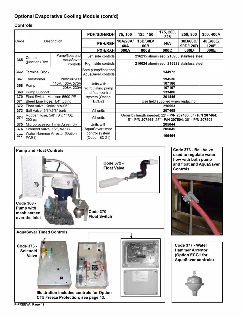
P-PREEVA, Page 4�
Optional Evaporative Cooling Module (cont’d)
Controls
Code Description
PDH/SDH/RDH 75, �00 ��5, �50 �75, �00, ��5 �50, 300 350, 400A
PEH/REH 10A/20A/40A
15B/30B/60B N/A 30D/60D/
90D/120D40E/80E/
��0EPXH/RXH 000A 000B 000C 000D 000E
365 Control (junction) Box
Pump/float and AquaSaver
controls
Left side controls ��6��5 aluminized; ��6908 stainless steel
Right side controls ��66�4 aluminized; ��69�8 stainless steel
366� Terminal Block Both pump/float and AquaSaver controls �4497�
367 Transformer 208/1or3/60tUnits with
recirculating pump and float control system (Option
ECD2)
�94536
368 Pump 115V, 460V, 575V �07�86208V, 230V �07�97
369 Pump Support �33486370 Float Switch, Madison 5600-PR �0�44637� Bleed Line Hose, 1/4” tubing Use field supplied when replacing.37� Float Valve, Kerick MA-052 ��6553373 Ball Valve, 5/8”x5/8” barb All units �07468
374 Rubber Hose, 5/8” ID x 1” OD, 200 psi All units Order by length needed: 22” - P/N 207463; 8” - P/N 207464;
15” - P/N 207465; 28” - P/N 207504; 36” - P/N 207505375 Microprocessor Timer Assembly Units with
AquaSaver timed control system (Option ECD1)
�05044376 Solenoid Valve, 1/2”, AA577 �05045
377 Water Hammer Arrestor (Option ECB1) �66464
Pump and Float Controls
AquaSaver Timed Controls
Code 368 - Pump with mesh screen over the inlet
Code 370 - Float Switch
Code 37� - Float Valve
Code 373 - Ball Valve used to regulate water flow with both pump and float and AquaSaver Controls
Code 376 - Solenoid
Valve
Illustration includes controls for Option CT5 Freeze Protection; see page 43.
Code 377 - Water Hammer Arrestor (Option ECG� for AquaSaver controls)

P-PREEVA, Page 43
Sequence of Operation with Optional Fill and Drain and/or Freeze Protection KitsApplies to: Float and Pump System with Optional Fill and Drain Kit (Option CT�, CT�, or CT3) �) Call for cooling.2) 2-way valve is energized and closes B to A.3) 3-way valve is energized opening B to C & closing A to C.4) During no call for cooling, valves return to normal state.Applies to: AquaSaver Timed Water System with Optional Freeze Protection (Option CT5)�) Call for cooling.2) 3-way valve is energized opening B to C & closing A to C.3) If outside air temperature drops below freeze protection
controller setting, 3-way valve is de-energized and Aqua-Saver �4V solenoid valve remains energized for eight minutes to allow complete system water drainage.
4) During no call for cooling, 3-way valve returns to normal state.
Applies to: Float and Pump System with Optional Fill and Drain Kit (Option CT�, CT�, or CT3) and Freeze Protection (Option CT6)�) Call for cooling.2) 2-way valve is energized and closes B to A.3) 3-way valve is energized opening B to C & closing A to C.4) If outside air temperature drops below freeze protection
controller setting, valves return to normal state.5) During no call for cooling, valves return to normal state.
CODE Component Description In Option P/N
3802-Way Solenoid Valve (field-installed)
115V CT1 5003�208V CT2 50�97230V CT3 50�99
38�3-Way Solenoid Valve (field-installed)
115V CT1 50033208V CT2 50�96230V CT3 50�9824V CT5 �78677
38� Temperature Controller* CT5 and CT6 ��6�70
383 Time Delay Relay* CT5 8966�384 Relay* CT5 ���4��385 Relay Socket* CT5 ���4�5
*Factory-installed in the junction box; see page 42.
�������������������������
������������������������������������������������
���������������������
��������������������������������������������������������
�����������������������������������������������������
��������������������������������������������������
����������������������������������������������
��������������������������������������������
��������
�����������������������������������������������������������������������������������������������������������������������������������������������������������������������������������������������������������������������������������������������������������������������������������������������������
����������������������������������������������������������������������
����
��������������������������������������
����������������������������������������������
�� �
�
�
������������������������������
Evaporative Cooling Module Optional Fill and Drain Kits and Freeze Protection Controls
Code 38� - 3-Way Valve
Code 38� - Temperature Controller
Code 383 - Relay
Codes 384 & 385 - Relay and Socket

P-PREEVA, Page 44
CODE DescriptionPDH/SDH/RDH 75, �00 ��5, �50 �75, �00, ��5 �50, 300 350, 400A
PEH/REH 10A/20A/40A 15B/30B/60B N/A 30D/60D/90D/120D 40E/80E/120EPXH/RXH 000A 000B 000C 000D 000E
386 Intake Screen ��7��9 ��7��0 ��7��� ��7��� ��7��3
387 Single Sprinkler Pipe Assembly - 6” media ��6850 ��685� ��6850 ��685� ��6853
388 Double Sprinkler Pipe Assembly - 12” media ��6846 ��6847 ��6846 ��6848 ��6849
389 Feed Line Assembly ��6854
�����������������
��������������������
�������������������
����������������������������������������������������
��������
�������
�������������������������
�����������������������������������������������������
��������������������
��������������������
�������
Single Sprinkler Pipe for 6” Media Double Sprinkler Pipe for 12” Media
Water Piping
www.RezSpec.com (800) 695-�90�©2010 Thomas & Betts, All rights reserved.Trademark Note: Reznor® and PREEVA® are registered in at least the United States. 1/10 Form P-PREEVA (Version E)
Optional Evaporative Cooling Module (cont’d)
Cabinet Parts for Option ECC Evaporative Cooling Module (factory-installed)
NOTE: If parts not listed are needed, contact your distributor or the factory service department.
Option ECC Evaporative Cooling Modules, factory-installed on PREEVA units
CO
DE
PDH/SDH/RDH
Con
trol
Si
de*
Type
of
Stee
l 75/100 125/150 175/200/225 250/300 350/400
PEH/REH 10A/20A/40A
15B/30B/60B N/A 30D/60D/
90D/120D40E/80E/
��0EPXH/RXH 000A 000B 000C 000D 000E
390Door (removable panel on control side)
Left Prepaint ��6��� ��6���SS ��6988 ��6989
Right Prepaint ��6877 ��6878SS ��70�9 ��7030
39�Non-Control Side Panel (not an access panel)
Left Prepaint ��6�00 ��6�0�SS ��6899 ��6900
Right Prepaint ��6365 ��6366SS ��69�� ��69��
39� TopLeft Prepaint ��6�7� ��6�73 ��6�7� ��6�74 ��6�75
SS ��6879 ��6880 ��6879 ��688� ��688�
Right Prepaint ��6��3 ��6354 ��6��3 ��6355 ��6356SS ��6909 ��69�0 ��6909 ��69�� ��69��
393
Post (control side where water connection is located)
Left Prepaint ��6��3 ��6��4SS ��6906 ��6907
Right Prepaint ��6357 ��3658SS ��69�3 ��69�4
394
Media Side Plate on Non-Access Side (vertical, inside of cabinet)
Left Alum ��6�98 ��6�99SS ��6897 ��6898
Right Alum ��6359 ��6360SS ��69�5 ��69�6
395Media Bottom Front Support (adjustable for 6” or 12” media)
Left and Right Controls - all SS ��6�68 ��6�69 ��6�68 ��6�70 ��6�7�
396 Media Bottom Rear Support (non adjustable) ��6�64 ��6�65 ��6�64 ��6�66 ��6�67
397 Cooler Drain Assembly (quantity 2) �57554 (Bushing 256911; Nut �569��; Gasket �57460)*Left or right control side is determined when facing the discharge end of the system.
���
���
���
���