
FORM NO. 838G READ CA:QEFULLY
30
READ CA:QEFULLY INSTRUCTION MATERIAL A D PARTS LIST 0 10-K LATHE D RADIAL DRILL D 10" LATHE D IBARMIA DRILL D 13" LATHE D CNC CYCLONE D 14" LATHE D 7" BENCH SHAPER D 16" LATHE D MILLING MACHINE D 16-24" LATHE D MECHANICAL PRESS D 17" LATHE D DEKA DRilL D 20" LATHE D DYNABLAST D D SELLER'S OBLIGATION FORM NO. 838G SEllER EXPRESSLY EXCLUDES ALL WARRANTIES, GUARANTEES AND REPRESENTATIONS, EXPRESS OR IMPLIED, INCLUDING BUT NOT LIMITED TO WAR- RANTIES OF MERCHANTABILITY, MATERIALS, WORKMANSHIP, DESIGN AND SUITABILITY FOR A SPECIFIED OR INTENDED PURPOSE. In lieu, thereeof, any goods which upon Seller's determination are defective due to faulty material or workmanship or are of Seller's design and are unsuitable for Buyer's specified or ordinarily intended use, as determined by Seller, will be repaired, or replaced, f.o.b. point of origin, or the unit purchase price refunded, at Seller's option; provided that the goods are returned (upon Seller's written consent first being given), or the some are rejected, in either event within six (6) months of their sale for mechanical presses, Deka-Drills, numerically contralled machine tools, automatic tracer lathes, milling machines, radial drills, geared hand drills or Dynablast equipment, and one (I) year as to other goods; except that as to goods purchased by Seller from others and ,. sold 10 Bu,yer or incorporated in Seller's goods, Buyer shall have whatever warranty is available from Seller's supplier which shall be Buyer's sale re- course. Seller shall not be liable for Buyer's loss of profit or any special or consequential damage or loss, nor for any cost incurred by Buyer for oltera- lion, repair or work done on Ihe goods wilhout Seller's express approval in writing prior to any such alteration, repair or work. Seller reserves Ihe right, 01 its own dlscretioh, without notice and without making similar changes in articles previously manufactured, to make changes in materials, design, finish, or specifications. Any production figures for machines are only estimates and ore not guaranteed. ® Bend the 400 WEST SAMPLE STREET SOUTH BEND, INDIANA 46625 ---- '.
Transcript of FORM NO. 838G READ CA:QEFULLY

READ CA:QEFULLY
INSTRUCTION MATERIAL A D
PARTS LIST
0 10-K LATHE D RADIAL DRILL
D 10" LATHE D IBARMIA DRILL
D 13" LATHE D CNC CYCLONE
D 14" LATHE D 7" BENCH SHAPER
D 16" LATHE D MILLING MACHINE
D 16-24" LATHE D MECHANICAL PRESS
D 17" LATHE D DEKA DRilL
D 20" LATHE D DYNABLAST
D D
SELLER'S OBLIGATION
FORM NO. 838G
SEllER EXPRESSLY EXCLUDES ALL WARRANTIES, GUARANTEES AND REPRESENTATIONS, EXPRESS OR IMPLIED, INCLUDING BUT NOT LIMITED TO WARRANTIES OF MERCHANTABILITY, MATERIALS, WORKMANSHIP, DESIGN AND SUITABILITY FOR A SPECIFIED OR INTENDED PURPOSE. In lieu, thereeof, any goods which upon Seller's determination are defective due to faulty material or workmanship or are of Seller's design and are unsuitable for Buyer's specified or ordinarily intended use, as determined by Seller, will be repaired, or replaced, f.o.b. point of origin, or the unit purchase price refunded, at Seller's option; provided that the goods are returned (upon Seller's written consent first being given), or the some are rejected, in either event within six (6) months of their sale for mechanical presses, Deka-Drills, numerically contralled machine tools, automatic tracer lathes, milling machines, radial drills, geared hand drills or Dynablast equipment, and one (I) year as to other goods; except that as to goods purchased by Seller from others and ,. sold 10 Bu,yer or incorporated in Seller's goods, Buyer shall have whatever warranty is available from Seller's supplier which shall be Buyer's sale recourse. Seller shall not be liable for Buyer's loss of profit or any special or consequential damage or loss, nor for any cost incurred by Buyer for olteralion, repair or work done on Ihe goods wilhout Seller's express approval in writing prior to any such alteration, repair or work. Seller reserves Ihe right, 01 its own dlscretioh, without notice and without making similar changes in articles previously manufactured, to make changes in materials, design, finish, or specifications. Any production figures for machines are only estimates and ore not guaranteed.
®
Bend the
400 WEST SAMPLE STREET SOUTH BEND, INDIANA 46625 ----'.

IMPORTANT
��:'.�' - l
/
South Bend Machine Tools are designed and manufac
tured to assure you the greatest measure of long life performance. There remains, however the important factor of getting prompt service when replacement parts are required as a result of natural wear or accidental damage. This parts list was prepared for your convience to determine quickly the part needed.
PARTS AND ASSEMBLIES. Frequently replacement parts are ordered that appear to be individual parts but in reality the particular part ordered is attached to other parts by press fit, hand scraping, tapered pins or by some other mechanical means which can only be prop
erly done in our factory, and are part of an assembly. The part numbers with prefixes "e" and "AS" identify assemblies and the parts included in these assemblies are indicated by the item numbers appearing in parenthesis after the part name. Such parts are not sent out individually, but as assemblies.
SERIAL NUMBER, LATHE, VERT. MILL, SHAPER, MECH.
PRESS, HYD. PRESS & MODEL NUMBER DRILL PRESS.
This number must always appear on your order for replacement parts or attachments to assure prompt shipment of the part or attachment ordered. This number is an index as to the size, type and model of your machine, also date the machine was built. Location of these numbers illustrated at right.
CODE NUMBER. This number should also appear on your order of replacement part. This number is an index to the specific design of part that went into the unit assembly. We are continually making improvements on all South Bend Machine Tools. We may change the dimension or the appearance of a certain part, yet it is still interchangeable with the old part. You will always receive the benefit of the improved design on orders for replacement parts whenever interchangeability makes this possible. Location of this number (illustrated below) is shown on the repair parts sheet.
Therefore, when ordering we must have the follow-ing information:
1. Serial or Model No. of Machine. 2. Unit code number. 3. Part number & name of part required. 4. Quantity.
INDEX
FORM 983 B
SECTION 1 9" & 10K Lathes. 9" & 10K Toolroom Attachments. 9", 10K, 10" & 13" H. L. Bed Turrets. 911, 10K & 10" Ho La Double Tool Slides.
SECTION 2 10", 13", 14 1/2", 10" 13" 14 1/2" " ,
Attachments.
1611 & 16-2411 Lathes. 1611 & 16-2411 Toolroom
13" & 2H Turnstile Turrets. 13", 1611 & 2H Double Tool Slides. Coolant Pump.
SECTION 3 Lathe, Vertical Mill, Shaper, Drill Press
& Pedestal Grinder Accessories.
SECTION 4 Precision Drill Press Economy Dri II Press
SECTION 5
Shaper
SECTION 6 Pedestal Grinder
SECTION 7
Vertical Mil/ing Machine 900 MIl/ i ng Head
SECTION 8
17" Geared Head Lathe

4-5-65 SPECIAL INFORMATION FO�l 1038
CARE OF MACHINE TOOLS THAT ARE NOT IN USE
When a machine is taken out of service, such as in a school where they would not be
used during the summer months or at some other vacation or off period, it should be
properly taken care of as follows:
1. Thoroughly clean the machine, being sure that all surfaces are cleaned.
It is as important to clean the painted surfaces as well as the
machined surfaces. The machine should be cleaned with some type
of solvent if the machine has accumulated hard to remove deposits.
If all deposi ts are not removed and a protective coating is applied,
it will make the machine doubly hard to clean when the machine is
put back into service. A neutralizing agent should be used where
finger printing is common or where the climate is very damp.
2. After the machine has been thoroughly cleaned all of the machined
surfaces should be covered with either a good grade of medium weight
MACHINE OIL (NOT AUTO ENGINE OIL) or if the machine is going to be
out of service for a long period of time a light weight grease
(commercial petroleum jelly that has been thinned with naptha or
mineral spirits is very good) should be used. When covering the
machine surfaces care should be taken so that the machined surfaces
are completely covered. Also you should try and keep the oil and
grease off the painted surfaces.
3. If the machine has belts of any type, they should be loosened, so
that they will not stretch while the machine is not in use.
4. All poyer to the machine should be disconnected. Some machines
could be very easily damaged if run after being out of service for
a long period of time.
5. The machine should be covered with a cover that will keep dust and
dirt from accumulating on it. Also the cover should be liquid re
pellent to keep any liquid from coming into contact with the working
parts of the machine. Such a cover is listed in our General Catalog.
These covers are available for all sizes and types of machines that
we manufacture.
SOUTH BEND L ATHE South Bend Indiana. U. S. A.

B ACK G E AR AND ECC ENTRIC 9", 10K, 10" and 14!" lathes only
-Quill iar/ B - Bull Gear Guar� Guard
.� ,I,
Fig. 1
J - Eccentric Shaft ----'" Bushing
I. TO DISASSEMBLE:
H - Eccentric Shaft Assembly
Fig. 2
1. Remove items "A" and "B" (Fig. 1).
-� 2. Loosen screw "c" (Fig. 2).
S H A.F T
3. Remove items "Dfl thru "I" (Fig. 2) in alphabetical order.
I I. TO REASSEMBLE:
2000
1. Replace items "H" and "I". (Be sure gears are free of dirt, chips, and nicks.)
2 • Replace item "G fI and pin wi th item "F".
3. Replace item ttEII, locating the point of the screw in slot of eccentric shaft bushing IIJ" and replace nut "D".
III. ADJUSTING BACK GEARS: 1. Engage back gears using eccentric shaft lever "K" and allow mating gears to
bottom. T hen back off back gears until you feel a slight rock between mating gears and tighten set screw liE". Tighten screw "c" so tension on bushing "G" is enough to hold gears in mesh on heavy cuts, but not so tight that the eccentric shaft lever "K" is hard to operate. Make final adjustment by allowing lathe to run for a few minutes. I f there is an abnormal amount of noise such as a gear rattling noise the gear clearance is too great, adjust by slightly unscrewing set screw "E". If it seems to be a howling noise, the gear clearance is insufficient. Adjust by screwing in slightly set screw "E". When proper gear clearance is obtained, lock set screw "E" with nut liD" •
.. � IV. OILING
1. Remove plug ilL" and fill teflon grease. Use our CE1625 or equal.
SOUTH BEND LATHE South Ben d Indiana. U. S. A. !'rift'''' 1ft U.S.A.

SERIAL NUM BER OF LATHE AND UNIT CODE NUM BER 'MUST' ACCOMP ANY ORDER
4 ............ , ! J 5 -2-5/16" wide 3--G> �� L / I > G -2-3 1+" wide
� ,II� 2-8 II"
�cw 1�& V-18
1-·21 9" HORIZONTAL DRIVE HEADSTOCK
Mod e 1 A, B, & C
31 "32 33 37
eiE (-" --- - ��-t (---= (I \ 42 47 33-1 43 - fo) � SPINDLE ASSEMBLY
I T ��V"_BELT CoNE
45 46 i<44
SOUTH B END LAT H E
ITEM NO.
I 2 3 4 5 6 7 8 9
10 II 12 13 14 15 16 17 18 19 20 21 22 23 24 25 26 27 28 29 30 31 32 3J 34 35 36 37 38 39 40 41 42 43 44 45 46 47
38 3'1 I I o
PART NO.
IOIX606 IOOX300 IOOX204 101X306 PTl943N2 PTl942NI PTl48NI PTl49NI
*AS362NI 114X220 AS373NI PTlON4 PT377NRI PTl058NRl PT2677NRI PT365Nl PT366NI PTlI50NKI PTl3NKl PTl672NKl 112X1112 PT363Nl PT364Nl PT376NRI PT374NRI PTl075NRl 138X18 10lX316
*AS25NKI *AS26NKI
PT207NK I *AS 14NKI
PT381 NHI *ASI5NKI
PT367NRI PT214NR2 PT200N2 PT370N2
CL2175NK CL205NK
CE2401 PT382NKI PT2090
*AS432NK 2 160X23 PT433NKI PT383NRI
40 41
PART NAME
SCREW WASHER WASHER SCREW BRACKET, 2-5/16" BRACKET, 2-3/4" QUILL GUARD BULL GEAR GUARD SAFETY GUARD (27-28) SCREW CAPILLARY OILER HE AD STOC�
STOP SCREW NUT OILER LAM. SHIM SOLID SHIM SCREW CLAMP WASHER SCREW LAM. SHIM SOLID SHIM
SCREW
SPRING
SHOE NUT
SCREW
TAKE UP NUT (*30-42) TAKE UP WAS HER (47) THRUS T BEARING CONE (33) OIL PLUG SCREW
BULL GEAR (35-36) SPRING
PLUNGER
SPINDLE
PROTECTING RING FACE PLA TE 5 1/8" O. D.
SPINDLE SLEEVE
CENTER
SCREW
KEY
CONE (33-45-46) PIN "V" CONE PINION PIN
\\ ( m f"'(����
" AV A I L ABL E O NL Y A S S U B· A S SEMBL Y . PAR TS I NCLU D E D ARE INDICATED BY TH E I T EM NUMBERS A P P E AR I N G I N PARE N TH E S I S AF TER P AR T N A ME .
South Bend Indiana, U . S. A. Printed in U.S.A.

FORM 900F
48
SECTION , PARTS LIST
5Z'--::ii' - 1"--65 ./ 6Q// ... � � : l / Hote-l fiG The 20 tooth and �O 61;' �p iI -\7 s tud gears for the gea
� __ §/ 1 athe wi 11 be found on 6 3 ---- ./'II gear box parts sheet,
62/ .- Hos. �7 and 55.
64/@1'''''-''--68 ·'9-REVERSE BRACKET ASSEMBLY INCLUDES ALL PARTS S HOWN ABOVE
REVERS E BRACI<ET ASSEMBLY
10 71 / ""'n !/)/ / J3 74
D if:Jj/ � ·75
� / . ;&77 BACK GEAR ASSEMBLY � V
9" H OR I ZONTA L DR I VE HEAD STOCK Mode 1 A, B, & C
·AVAILABLE ONLY AS SUB· ASSEMBLY. PARTS INCLUDED ARE INDICATED BY THE ITEM NUMBERS APPEARING IN PAR· ENTHESIS AFTER PART NAME.
SOUTH BEND LATHE
Unit Code Number Stamp ed Here
9" TA I LSTOCK Model A, S, & C
tooth r box
the item
11 �
'11-15-64 ITEM PART
PART NAME NO. NO.
48 137><29 NUT 49 P128NKI REVERSE GEAR 50 256Xl FELT WICK 51 PT27K32NKI TWIN GEAR 52 256X14 FELT WICK 53 REVERSE BRACKET
*A5635K2 (52-60-65-*67) 54 139X25 NUT 55 256X3 FELT WICK 56 *AS637NKI REVERSE SHAFT (48) 57 P12585K2 LOCK BUSHING 58 PT409T1 SNAP RING 59 TWIN GEAR STUD
*AS229Kl (50-54) 60 155X38 OILER 61 P12584Kl PIN 62 P12586Kl BUSHING 63 162X35 SPRING 64 PT88NK2 PLUNGER KNOB 65 PT1501 PLUG 66 164X85 KEY 67 REVERSE PLUNGER
*AS640KI (61-62-63-64-68) 68 16OX10 PIN 69 REV. BRACKET ASSEMBLY
(49-51-*53-55-*56-57 *AXS635K2 58-*59-66)
70 168X312 TAPER PIN 71 P124NK2 ORDER ITEM 75 72 *AS361NK2 BACK GEARS (73-74) 73 PTll51NI SCREW 74 PT378NKI WASHER 75 EcaNTRIC SHAFT
*AS202NKI (70-71-76-77) 76 168X310 TAPER PIN 77 PT438NKI ORDER ITEM 75
SERIAL NUMBER OF LATHE AND UNIT CODE NUMBER 'MUST' ACCOMPANY ORDER
ITEM PART NO. NO. PART NAME
I CE2401 CENTER
2 P1201 NRI SPINDLE
3 PT54NKI LEVER
4 PT50NI T. S. TOP
5 PT283NKI NUT 6 PT2861 NKI WASHER 7 CE2653N T. S. WRENCH
8 P1278NKI SCREW
9 *AS226N2 T. S. SCREW (9A) 10 PT52Nl T. S. NUT 11 *AS53NKI HANDWHEEL (12-17) 12 PTI480 HANDLE 13 PT286NRI SPINDLE KEY 14 PT51NI T. S. BASE 15 PT56NK2 ClAMP 16 143X214 CLAMP BOLT 17 168Xl06 PIN 18 PT3554NRI RUBBER WASHER
South Bend Indiana, U.S . A.
"'--.

'* 2
1
9" & IO-K Mod I
APRON e A & B
b 1 PT1481 2 'AS71 NK1 3 168 x 108 4 P170NK1 5 155 x 23
30
1
\ c:?
36 37
SERIAL CODE
NUMBER 0 F L NUMBER"M
ATHE AND U usr" A
NIT CCOMP AN Y 0 RDER
o
� 160xl8
8 *AS76NK1 122 x 208
16 *AS87NKI
11 PT204J N K I
12 PT85NK2 256 x 3 :� AS228NK2
15 'AS231 NK2
16 *AS225NKI
17 PT409NKI
18 PT83NKI
19 PT86NKI
20 PT80NKI
21162x19
22 P177NKI
23 PT352NKI
24 PT353NKI
25 *AS223NK2
26 PT349NKI 160 x 22
27 PT2677NRI �� 120 x 108
30 PT2854N K 1
31 PT355NFI
32 168 x 210
33 160 x 10
34 *AS88NK2
35 *AS84NKI 162 x 35
36 PT89NKI 37 PT82NKI 38 PT1511 39 160 x 76 40 137 x 25 41 122 x 604 42 162 x 5 � PT351NKI
45 PT97NK2 160 x 19 � PT690NKI
48 *AS203NKI
49 PT208NKI
50 PT172NKI
51 *AS350NKI
52 *AS72NKI PT357NKI �� PT412NKI
9" & IO-K Model C
APRON 55 *AS227NK1
56 101 x 104
• ' ' ' ' "'"
57 'AS76JNKI
ASSEMBLY P ONLY AS SU
58 PT204JNKI
SOUTH
'"' . '"" ,. AS228
'" """ "" c." 59
JNKI
�1:)T��;;:;::-:;�����:: ��: �S I� S�
A�P �P:E ;
A: R �� /� � pi TEM 60
122 x 606
BEN D AFTER p
AR-61
162 x 34
LA THE ART NAME.
62 AS74JNKI
, I NC. __
____
___
�=�=P17= �O�JNKI
PART NAME
Handle
THondwheel (I 3 '7) oper Pin "
Apron Oiler Pin Gear (6,10) Screw Pinion (6,11) Order Item 7 Order Item 9 Felt Wick Stud Shaft (52) Pinion (16) Spring Shifter Gear Sleeve Spring Gear Shoes (Pair)
SExpanders (Pair) crew (26 30)
Spring ,
Pin Oiler Screw Oil Tube Screw Taper Pin Pin Knob (32 35 3 L
" 6)
ev.er (17,31 :33) Spring Order Item 33 Knob Pipe Plu P•
g In
Nut Screw Spring Pin Plunger Pin Key Worm (45 46 Collar '
,48)
Pin Screw (40)
HoI.f Nut (49) SPring Gasket Traugh (53,55) Screw Gear (6,57) Order Item 56 Stud Screw Spring Cam Apron
Indiana U S , . . A Printe" in U.S
-.A.

FORM 902D S EC T I ON 1 1 l;t +;--, 1-1 , 9 Mod. A & B (No Taper Att.) 10 -Mod. A & B (With Taper Att.)
--7 �c::====1:J�llIIIIII:ammIDlllIIlm1DIfIIIll:D/ /
11 Hod. C (No Taper Att.) / 12 -Mod. C (Wi th Taper Att.) / /-- - ----- --- -_ "---./
/ /� / <:::::') (;) ����" / . ; !:;««,' P /1 13 14 15 U. • , • • •
I / I
/1 18 -4l 1-19 -I ... 18 1 20/A 21 -A * h, 1 � 24 25 'IJ 1fT' 26 I 23 _I -22_� � l� ____ �O������3�
Unit Code Number Stamped Here
* 40
/ • 0
27 22 -.#' 18 t �/O
,-\ \ " "\ 11::::.- 25
i. . . . . I �\ C36 26
33 e..... * ,.22 " ,fl 34 35 �-20 ... ��
�-18 ::�I 21 � �� � 30� ,
9 n & I O-K SADD LE & COMPOUND REST
St y I e A Style B
39-@ * �J�41-___ 42
:'::----rl · 45 roc ,"
� IlJ r" 10-<
~ ....... 1 �� U nit Code Number Stamped Here
/� 55 14 • 53 56 - 9 57 - 10 K
*Ava ilable only as sub-assembly. Parts included are indi-cated b y the item numbers appearing in parenthesis after part name.
SOUTH B END LATHE. INC.
11-15-64 ITEM PART NO. PART NAME NO
1 PT295R1 Nut 2 PT1480 Handle 3 160 x 17 Straight Pin 4 *AS276NK1 Ball Crank (2) 5 *AS64NK1 Collar (6,7) 6 122 x 103 Screw 7 PTlO76NR1 Binder Shoe 8 PT63NK1 Bushing 9 *AS224NK2 Cross Feed Scr. (1,
*4,*5,8,*35) 10 *ATA224NK2 T.A.C.F. Screw
(1,*4,*5,8,16,17) 11 *AS224JNK2 C. F. Screw
(1,*4,*5,8,*35) 12 *ATA224JNK2 T.A. C. F. Screw
(1,*4,*5,8,16,17) 13 *AS485NK1 T. A. Base
(14,15,25,26) 14 122 x 444 Screw 15 PT874NK1 Gib 16 PT66NK1 Screw 17 PT486NK1 Cr. Feed Nut 18 107x6 Screw 19 PT244NK1 Saddle Screw 20 PT58NK1 Retainer - R 21 PT57NK1 Retainer - L 22 PT59NK1 Felt Wiper 23 122 x 102 Screw 24 *AS92NK2 Base
(14,25,26,36) 25 PT211NK1 Shoe 26 121 x 212 Screw 27 AS60NK2 Saddle 28 PT210NK2 Lock Screw 29 AS62NK2 Lock 30 112 x 114 Screw 31 PT3400 Washer 32 PT61NK1 Gib 33 PT358NK1 Pin 34 PT359NK1 Lock Screw 35 *A665NK1 C.F. Nut (33,34) 36 PT221 NK1 Gib 37 CE2650NK Wrench 38 PT233NK1 T. P. Scr.ew 39 PT251 NK1 Ring 40 *CE2450NK Tool Post Ass'y. 41 PT209NK1 Block 42 PT209NK2 Block 43 *AS250NK3 Tool Post (41 or 40 44 PT252NK2 Wedge 45 *AS90N1 C. R. Top (*52,
14, 53, 56) 46 *AS90K1 C. R. Top (*52,
14, 53, 57) 47 PT295NR1 Nut 48 PTl480 Handle 49 *AS277NR1 Crank (48) 50 *AS110NK1 Collar (6,7) 51 PT94NK1 Bushing 52 *AS230NK2 Screw (37, *49
50,51,55) 53 PT257NK1 Gib 54 122 x 508 Screw 55 PT95NK1 C.R. Nut 56 PT91 N1 Swivel 57 PT91 K1 Swivel
Prices Net. F.O.B. South Bend, Ind. (Subject to change without notice)
Indiana. U. S.A. Printed in U.S.A.

9" & IO-K GEAR BOX Model A
/'57
� ® (JQrz:::::zl..--..J-f--J:; @:� @:e \ I I i *1 i / I *' I \ .' \ 1 2 3 4 5 6 7 8 9 10 11 \ \ \ \ \ \ \ \ \ \ \ \ \ \ \ \
/ 15
� S_"'TU C�&> L "'rl-l, [.-, S • ."rv dFNP I r"':'E::: ,:i-·:II .... .$�_
,L!·Wlll:·1-�" . �"I{�" � I t· , 'II '. t.. • � • ..
'" . 16--6
\ /' 17 \ 18 I . � \ \ .=-l� __
� /
22 0 0 0
Q 13 /'
@) I
12
----..,
Unit Code Number Stamped Here
«(
o •
/ 25
\ \ I I \ \ \ \ \ \ \ I \
GEAR BOX PARTS
!TEN PART PART NO NO. NAME
I 140 x 29 Nut 2 161 x 73 Washer 3 164 x 86 Key 4 *AS603NKI Shaft (1,2,3,5,12,13) 5 164 x 17 Key 6 PT627NKI Order Item 8 7 160 x 17 Straight Pin 8 *AS625NKI Camp. Pinion (6,7) 9 PT626NKI Order Item II
10 160 x 16 Straight Pin II *AS619NKI Camp. Pinion (9, 10) 12 PT604NKI Collar 13 168 x 108 Taper Pin 14 *AS 1541 NK3 Index PIt. (15) 15 132 x I Screw 16 155 x 38 Oiler 17 256 x 3 Felt Wick 18 PT606NK2 Bushing 19 160 x 31 Straight Pin 20 AS600NKI Gear Box 21 PT628NKI Lead Scr. Gear 22 PT601 NK2 Bushing 23 III x 6 Screw 24 160 x 19 Pin 25 PT607NKI Guide Bar 26 PTI807 Pin 27 160 x 27 Pin 28 *AS88R2 Knob (27, 38,39) 29 PT610NRI Bushing 30 *AS605NKI Gear (33) 31 160 x 42 Pin 32R *AS400NK2 R. H. Tumbler (27
28,29,30,31,33,38,39 32L *AS40INKI L. H. Tumbler (27
28,29,30,31,33,38,39 33 PT384NKI Bearing 34 160 x 252 Shaft 35 PT620NKI Shaft 36 256 x I Felt Wick 37 PT62 I NKI Gear 38 162 x 50 Spring 39 PT608NRI Plunger 40 PT624NKI Gear 41 PT626NKI Order Item 43 42 160 x 16 Pin 43 *AS623NKI Pinion Gear (40,42) 44 PT626NKI Order Item 45 45 *AS622NKI Pinion Gear (42,44) 46 PT615KI6NKI Cone Gear 16T 47 168 x 310 Taper Pin 48 PT615KI8NKI Cone Gear 18T 49 PT615K20NKI Cone Gear 20T 50 PT615K22NKI Cone Gear 22T 51 PT615K23NKI Cone Gear 23T 52 PT615K24NKI Cone Gear 24T 53 PT615K26NKI Cone Gear 26T 54 PT615K28NKI Cone Gear 28T 55 160 x 251 Pin 56 *AS614NKI Shaft (55,57,58) 57 256 x I Wick 58 164 x 22 Key
Continued on reverse side Pri ces Net F. O. B. South Bend, Ind. (Subject to change without notice)
------ - -----------40
\ 49
\ 50 51 52 53 54 55 -lit \ , \ \ \ \ 56
----l I � @ ����� -= \ &���&r� -� __ -1
-AVAILA BLE ONLY AS SUB.
ASSEMBLY. PARTS INCLUDED
ARE INDICA TE D BY THE ITEM
NUMBERS A PPE ARING IN P AR
E NTHESIS A FT E R PART NA ME.
SERIAL NUMBER OF LATHE AND UNIT
CODE NUMBER 'MUST' ACCOMPANY ORDER
SOUTH B END LATHE
57
South Bend Indiana

FORM 903E SECTION , PARTS LIST S erial Number of lathe and Unit ,'7-( 20T C ode Number MUST AccOIIIpan y 0 rde r •
"I 50""
55-( 4 0T. Stud Gear )
Stud Gear )
'AVAILABLE ONLY AS SUB
ASSEMBLY. PARTS INCLUDED
ARE INDICATED BY THE ITEM
NUMBERS APPEARING IN PAR
ENTHESIS AFTER PART NAME.
9" & IO-K GEAR BOX Model A
NOTE: This Guard, With Screws, Item No. 57A Also Used On
* Mode 1 s BAnd C.
� Model
�10 \ Mode I BPI at e
::�.:: -.. � ,. ...
I \
2.7 9" & IO-K STANDARD CHANGE GEAR Model B & C
SOUTH BEND LATHE
2G
12
I1£H NO.
47 48 49 50 51 52 53 54 55 56 57 58
ITEM N O.
I 2 3 � 5 6 7 8 9
10 " 12 13 14 15 16 17 18 19 20 21 22 23 2� 25 26 27
11-15-64 GEAR BOX PARTS
PART PART NO. NAME
PT3 2K20NKI GEAR, 20 T. 140X 29 NUT \ '--..
161X 21 WASHER PT33NKI I DlER GEAR PT38NKI BU SH I HG
*AS3 INKI BRACKET (53) II�x 228 SCR EW
* AS247HKI BOLT (48-49) PT3 2K40NKI GEAR, 40 T. PT3 2K56NKI GEAR, 56 T. PT389NK 3 . GUARD PT II 50NR I SCREW
STANDARD CHANGE GEAR PARTS
PART PART '--
NO. NAME
I �OX29 HUT 161X21 WASHER AS336NKI COMPo GEAR,18/5�T
PT38NKI BUSH I NG • AS31NKI BRACKET (8) 'AS2�7NKI BOLT (1-2)
AS36NKI COMPo GEAR,18/7.2T
IIlt-X228 SCREW PHNKI FRONT BRACK ET
ASI525 NK3 INDEX PLATE AS 1527J NR2 INDEX PLATE PT32KI6NKI CHANGE GEAR, 16T PT32K24/j KI CHANGE GEAR, 24T PT32K3 2N KI CHANGE GEAR,32T PT32K36NKI CHANGE GEAR,361 PT32 KltON KI CHANGE GEAR, �OT PT32Klt�NKI CHANGE GEAR, � 4T PT32Klt6N KI CHANGE GEAR,46T PT32K48HKI CHANGE GEAR,48T PT32K52NKI CHANGE GEAR,52T PT32K54NKI CHANGE GEAR,54T PT32K56NKI CHANGE GEAR,56T PT32K60ltKI CHANGE GEAR,60T PT32K80NKI CHANGE GEAR,80T PT33HKI IDLER GEAR, 80T • AS32NKI CHANGE GEARS
132XI SCREW
Sou th Bend Indiana, U. S.A.

10-1-66 ' FORM 904F SECTION 1
911 & 10-K HORIZONTAL DRIVE UNIT
2 "16 !
@1 ... @ 0'0
\7\ \ Un i t Code Number • • 20 21 2�" '" 'm
FOR PROPER "V" PULLEY AND , "V" BELT SEE FORM 921 � @
� "q�;,o � 24 25----------·
.. �
SERIAL NUMBER OF LATHE AND UNIT CODE NUMBER " MUST" ACCOMPANY ORDER
"<7<For lO-K Gap Bed Lathes Only
TEM PART NO. PART NAME NO.
1 PT1945N1 Lever 2 170 x 206 Cotter Pin 3 170 x 206 Cotter Pin 4 AS1960N3 Shaft & Pulley 5 PT3658Rl Oilite Bearing 6 155 x 38 Oiler 7 PT1676NKI Washer 8 AS735NRI Collar (9) 9 120 x 206 Screw
10 *AS 103NK1 Cone (14, 15) 11 *AS431 NK2 Cone (12, 13) 12 139 x 25 Hex Nut 13 120 x 112 Screw 14 139 x 27 Hex Nut 15 120 x 212 Screw
SOUTH B END L AT H E
ITEM NO.
16 17 18 19 20 21 22 23 24 25 26 27 28
*/��� 10 11 12 13 14 15 \ �1 v� '-' ' - ,
5
�27
PART NO.
139 x 27 PT1946N1 PT1948N1 PT395Nl 112 x 224 PT1949NK3 PT1946K l-G PT1373 PT243NR1 139 x 29 PT1944N1 CE2323N *AS1940N3
'AVAILABLE ONLY AS SUB· ASSEMBLY. PARTS INCLUDED ARE INDICATED BY THE ITEM NUMBERS APPEARING IN PAR· EN TH E SIS AFT E R PAR T N AM E •
PART NAME
Hex Nut R . H. Rod Turnbuckle L. H. Rod Hex . Cap Screw Pin R. H. Rod Chip Guard Pivot Screw Hex Nut Base Belt I-Ply Standard (6, 5)
South Ben d Indiana, U. S.A.

9041=" SECTION 1 PARTS LIST
I g' & IDK UNDERNEATH DRIVE UNIT I
5
� 45
·AVAILABLE ONLY AS SUB
ASSEMBLY. PARTS INCLUDED
ARE INDICATED BY THE ITEM
NUMBERS APPEARING IN PAR
ENTHESIS AFTER PART NAME.
FOR PROPER w V " PULLEY ANO
" V " BEL T SEE FORM 921
SOUTH B END LATHE
Serial Number of Lathe and Unit Code Number MUS T Accompany Order
ITEM PART PART NO. NO. NAME
I 120X 206 SCREW 2 PT2611 HKI COLLAR 3 PT260SNI LOCK PIN � PH06KUHI KNOB 5 PT2609HKI H AH DL E 6 I 39X29 HUT 7 112X336 BOLT 8 112X22� HOLT SA 5't2 X't06 BOLT 9 PT26'tOH KZ CRADLE SUPPORT
10 AS't17HKI PLAT E I I 120XI 06 SCREW 12 160XI16 PIH 13 * AS2605NKI SHAFT (11-12-20
21-22- 23) I� PT390NK 2 PIVO T SCREW 15 167XIt WASHER 1 6 180X302 LOCK WASHER 17 13SX27 NUT IS 121 XI12 SCREW 19 139X25 NUT 20 PT26.00NKI CRAN K 21 16SX�IO TAPER PIN 22 161 XI7 WASH ER 23 PT260ltNKI RELEASE PIN 21t * AS2607NK2 BRACKET (25) 25 PTI82�-3 PIN 26 161X 21 WASH ER 27 PT3658-1 Oilite Bearing 28 PT25'tOHK 3 CRADLE 2SA 29 PT263SHTI SPR I NG 30 161XI't WASHER 31 112X 116 SCREW 32 PT2600NKI R. H. SC REW 33 AS2606NKI TU RN BUC K L E(33-34) 33A 120X6 SCREW 33B PTI081NTI SHOE 3� PT260 I NKI L. H. SCREW 35 P Tl949tlK2 CLEVI S PIN 36 AS735NRI COLLAR 37 PTl676HKI WASHER 3S ASI96 0 N3 SHAFT & PULLEY 39 112X232 BOLT 'to I 55X4't OILER '+1 PT2615NK I PIN 't2 P12614NKI SPRING �3 * AS2613NK I COLLAR (44) �'+ 120X10!! SCREW �5 I �� XI SCREW �6 -AS 103 N KI C. S. CONE(lt7-�S) 47 139X27 NUT 4S 120X212 SC REW It9 50 51 PT260SKI COVER LOCK ROD 52 *AS�3INKI C.S. CONE(53-54) 53 139X25 NUT 54- 120Xll2 SCREW 55 170X 2 06 C. PIN
South Bend Indiana, U. S.A.

6-\-65
.-"""" ,
911 HANDWHEEL COLLET AlT.
� MODEL A B & C :l)-� � ""1 U
S-G
911 HANDLEVER COLLET ATT. OLD STYLE MODEL A, B & C
Code Number Stamped Here
911 HANDLEVER COLLET ATT. NEW STYLE MODEL A, B & C
SERIAL NUMBER OF LATHE ANO UNIT CODE NUMBER 'MUST' ACCOMPANY ORDER
30--_ "AVAILABLE O NLY AS SUB
ASSEMBLY. PARTS INCLUDED ARE INDICATED BY THE ITEM NUMBERS APPEARING IN PARE NTHESIS AFTER PART NAME.
SOUTH B EN D L AT H E
FORM NO. 907J SECTION
ITEM PART PART N O. NO. NAME
I AS793 Nij DRAW BAR ASH. 2 PT99 5NK I KNOCK-OUT NUT 3 CE273lJ SPANNER W RENCH ij * AS795NI SLEEVE (5 ) 5 PH9 3NH I KEY
I PT978NI ADJUSTI HG NU T 2 * AS98SNKI YOK E SECTOR ( 15) 3 ij PT986N3 Order Item II 5 PT983HK I SNAP RING 6 PT97 5N2 DRAW BAR 7 PT9811l2 COLLAR 8 PH88N2 BALL RETAINER 9 17 2x20 CAM BALL
10 PT979H3 SLEEVE I I * AS979H3 SLEEVE(ij-5-7-8-9
12 16- 17- 18- 19-21)
PT995NKI KNOCK- O UT NUT 1 3 CE273lJ SPANNER WRENCH 14 PH90NH I STOP NUT SC REW 1 5 256xll WICK 16 PT l823 PIN 17 PT9 S lJNH I SHOE 18 162x52 SPRI NG 19 PTlJ89NHI SCREW 20 ItiOX58 PIN 21 PT976N I SNAP RING 22 * AS795N I SLEEVE (23) 23 PH93NHI KEY 24 PT990 N K I YOKE LEVER 25 PH9 2N R& TI SCREW, WITH H OLE 26 PTlJ9lJ N R &II YOKE HUT 27 tS5x5 OILER 28 PT991 NKI YOKE BOLT 29 PT377NRI SCREW 30 PT I058NRI NUT 3 1 PT993NK2 YOKE BRACKET 32 PT997HK I BRACKET STUD
I PH809 RHI SHOE 2 1 20X903 SET SCREW
3 CE239 2 W RENCH lJ 1 26x503 SET SCREW 5 PT I 078R H I SHO E 6 PT1859-1 PIN 7 *AS9B8NKI Y OKE SEGt-1ENT(8) 9 256xll FEL T WI CKS 9 PT986NlJ CLUTCH YOKE CONE
10 PTI823 PIN II P1983NK I CON E SM AP RING 1 2 PT975M 3 DRAW BAR 13 PT98 I N2 C OlLAR lij PH 88N2 BALL RETAINER 15 I 72x2 0 STEEL BALL 16 PT979 NlJ CLUTCH SLEEVE 17 1 60x5 8 SPINDLE P IN 18 PT976N I BAR SN ir RING 19 * AS978N 2 CL. ST P N UT( 1- 2) 20 *AS99B N I LOCK C L LAR (lJ-5 ) 21 PT99 5NKI KNO CK OUT N ur 22 CE273lJ SPANNER WRENCH 23 PTij9 3M H I KEY 2ij * AS795N I SLEEVE (23) 25 1 55x5 OILER 26 P TlJ9 ijN R&T I YOKE LEVER NUT 27 PH9 2 NR& TI YOKE LEVER SCREW 28 P1990NK I YOKE LEV ER 29 PT377NR I SCREW 30 PTI058NRI JAM NUT 31 P T991MKI YOKE SOL T 32 PT99 3NK 2 YOK E BRACKET 33 PT997NK I BRACKET STUD
South Bend Indiana

FORM NO. 907J SECTION 1
3 lO-K HANDWHEE L COLLET A TT.
\ MODEL A, B & C
( @
lO-K HANDLEVER COLLET ATT. OLD STYLE MODEL A, B & C J .#
\ *2-.11 J t i '\ V '\ to, �\tI � lO � GICt • ®:W:CfJ 0 \� r .a� D� ;;;: \.� 12 -, 13 ��4 15 16 '17 18 tCJ 20 21-Q '2.1 23
---I i/ � QVJ_26 l4� :�t5 �-27
lO-K HANDLEVER COLLET A TT. NEW STYLE MODEL A, B & C
·AVAILABLE ONLY AS SUB
ASSEMBLY. PARTS INCLUDED
ARE INDICA TED BY THE ITEM
NUMBERS APPEARING IN PAR
ENTHESIS AFTER PART NAME.
IT EM NO.
I 2
3 �
I 2 3 � 5 6 7 8 9 9 A
10 II 12 13
I� 1 5
16 17 18
19 20 21 22 23 2� 25 26 27
I 2 3 4 5 6 7 g 9
10 I I
12 13 14 15 16 17
18 19 20 21 22 23 24 25 26 27 28 2� 30 31 32 33
SOUTH B END L AT H E South Bend
PART PART
NO. NAME
AS798 K I HANDWHEEL
PT794kl DRAW BAR SLEEVE PT793K I DRAW BAR
'"AS793 KI D RA W BAR U -2-3)
PT978KI ADJUSTIHG HUT *AS988HKI YOKE SECTOR ( 13 )
PT986KI Y OKE C()jE PT983HKI SNA P RIHG PT97SKI DRAW BAR PT981KI COLLAR PT488KI BALL RETAINER 172X20 CAM BALL PT979K I SLEEVE
160X58 PIN PT995NKI KNOCK-OUT HUT CE2734 SP AHNER Wi\EHCH PT�90NHI STOP NUT SCREW 256XI I WI CK PTI823 PIN PT98�NHI SHOE 162X2 SPRING PT489NHI SCREW PH09R I SNA P RING PT990HKI YOKE LEVER
PT492 HR&T1 SCREW-WITH HOLE PH9 4NR&T1 YOKE NUT 155X5 OILER PT991HKI YOKE B OLT PT377N RI SCREW PT 10 58N RI NUT PT993HKl YOKE BRACKET PT997HK I BRA CKET SlUD
PTIIS 09 RH I 120x903 CE2392 126x503 PT I 078R H I PT1859-1
* AS98BNK I 256)(11 PT986K2 P T I 823 P1983NK I PT97SK2 PT981 K I PT48 a li I 172)(20 P1979K2 160)(58 PH09R I AS 978K2
*AS998KI PT995NK I CE2734
SHOE SET SC REW WRENCH SET SCREW SHO E PI N Y OKE SEGMEHT ( 8) FEL T WI CKS CLUTCH YOJeE CONE PIN CON E 3M AP R I NG DRAW BAR COLLAR BALL RETAI NER S TEEL BALL CLUTCH SLEEVE SPINDLE P IN SPR I NG CL. STOP NUT( I -?l LOCK COLLAR ( 4 -5 ) KNO CK OUT N ur SPAHNER WRENCH
1 55)( 5 0 I LER PT49Q.H R&T I YOKE LEVER NUT PT4 92NR&TI YOKE LEVER SCREW PT990NK I YOKE LEVER P T377N R I S CR EW PTl058NRI JAM NUT P T991NK I YOKE BOLT P199 3NK2 YOKE BRACKET PT997NK I B RACkET ST UD
Indiana
"-..

BELTS AND LUBRICATION !AI TEXALON FLAT BELTS. A combination of textile and
extruded nylon form a strong flexible belt recommended for use with South Bend Lathes. Able to withstand continual flexing without significant stretch and loss of efficiency. Texalon belts are skived on both ends and cement for joining skived ends is included with each belt. Shipping weight each approx. 1/2 lb.
Type of Drive Cat. No. Type of Drive Cat. No. ---- ---
9" HMD CE3750N 13" UMD 3·Step CE3753T
10·K HMD CE3750K 14Y," UMD 4-Step CE3752F
9" UMD CE3752N 14 y," UMD 3-Step CE3753F
10·K UMD CE3752K 16" UMD 4·Step CE3752H
10" UMD Bench CE3753R 16" UMD 3�Step CE3753H 10" UMD Floor CE3752R 16·24" UMD 4-Step CE3752V 13" UMD 4·Step CE3752T 16·24" UMD 3·Siep CE3753V
16" Turret CE3753H
� TEXALON BELT CEMENT for bonding skived ends of Texalon Belts.
CE1887. Texolon Belt Cement '.4 oz. bottle
CE2323N. Oak'
tan singl� ply Ilat leather belt without cord reinlorcing lor 9" Horizontal Motor Drive only. Has square ends and lace lor joining. Price f.o.b. lactory
!9 BELT SPLICING CLAMPS. For gluing skived ends of cone pulley belts or other flat leather belts. Made of heavy
steel plate with guide for aligning edges of belt ends.
Maximum Size of Belt Ship. Catalog
Number Widlh Thickness I Skive Length WI.
CE1898 1 ',4" y," 6%" 4 Ibs. CE1899 3" y," 6'10" 5 Ib,.
[QJ LU BRICATING OIL. Nothing is more important to the sat-isfactory operation and life of fine machinery than correct
lubrication. The lubricating oils listed below have been thoroughly tested in our research laboratory and are highly recommended. It is essential that the correct type of oil be used for the lathe spindle, lathe apron and shaper oil reservoirs and general lubrication. A supply of each kind of oil should be kept on hand and used as needed. The Say bolt viscosity of the various oils is indicated in seconds at lOO°F.
Cat. No. Viscosity Quantity I Ship. Wt. I General Lubricating Oil (See Oil Chart for Individual Machine)
CE1603 CE1906 CE2019
240·500 240·500 240·500
1 quart 12 quarts Gal. can
3 Ibs. 31 Ib,. 11 Ib,.
Oil for Spindle Bearings of South Bend Lathes (For other components see Oil Chart for Individual Machine)
CE1600 CE1905 CE2017
100 100 100 I 1 quart I 3 Ib,. I 12 quarts 31 Ibs.
Gal. can 11 Ibs.
Oil for lathes and Shapers (See Oil Chart for Individual Machine)
CE1602 CE1904 CE2018
150·240 150-240 150·240
1 quart 12 quarts Gal. can
31b,. 31 Ib,. 11 Ib,.
SOUTH BEND LATHE
LEATHER V-BELTS FOR CONE PU LLEYS
Lathe cone pulley V-belts can be re- CD' (, placed without disassembling the lathe ' headstock or drive unit by using these cord reinforced leather V-belts. Belts are skived for gluing and belt splicing cement is included.
Cat. No.
CE5L61 L CE5L62L CE5L54L CE5L51L
Size Lathe Drive Ship. WI.
9" U.M.D. 1 lb. 10·K U.M.D. 1 lb.
9" H.M.D. 1 lb. 10·K H.M.D. 1 lb.
NOT P ERMI SSABLE TO SHIP BY MY 0 F TH E AI R SER\l1 CES
Rubber V-Belts Rubber V-Belts for use with South
Bend Lathes and other power driven machinery. Specify cataloq number, maximum width, and outside circum-ference when ordering. Ship. wt. each, approximately
Catalog Num.her
CE3L210 CE3L220 CE3L230
CE4L280 CE4L290 CE4L300 CE4L310 CE4L320 CE4L440 CE4L4S0 CE4L460 CE4L470
CESL380 CESL400 CESL410 CESL420 CESL430 CESL440 CESL450
28' 29' 30' 31' 32' 44' 45' 46' 47'
38' 40' 41' 42' 43' 44' 45'
Catalog I OuUide Number Length
V-Balta with �'Top Width
V-Balta with �'Top Width
CE4L480 48' CE4L490 49' CE4L530 53' CE4L540 54' CE4L580 58' CE4L800 60' CE4L640 64' CE4L700 70' CE4L800 SO'
V-Balta with %' Top Width
CESL460 46' CESL470 47' CESL490 49' CESL500 SO' CESL510 51' CESL520 52' CESL550 55'
Chuck Wrenches
Y2 lb.
Catalog Size Shipping NUlnbe:r Square Weight
CE2748 . 277' 2 lb • � � CE2142 .297' lib. CE2143 .375" 2 lb •. CE2749 .400" 2 lb •. CE2744 .420' 2 lb •. CE2746 .570" 2 lb •. C===::tO'l-l __ Sizes of Wrenches Required
for Various Sizes of Chucks Cat. No. Size of Type of Si.e Cat. No. of
of Chuck Chuck Chuck Square Required Wrench
CL4OO6NK 6' Independent .297' CE2742 CL4206NK 6" Independent .297' CE2742 CL4006R 6' Independent .297' CE2742 CL4206R 6' Independent .297' CE2742 CL4201R 7�" Independent .420' CE2744 CL4006L 6' Independent .297' CE2742 CL4206LQ 6' Independent .297' CE2742 CL4207LQ 7 �/2f1 Independent .420" CE2744 CL4209Q 9' Independent .420' CE2744 CL4201MH 7W Independent .420' CE2744 CL4209MH 9' Independent .420' CE2744 CL4210MH 10" Independent .420' CE2744 CL4212H 12" Independa,1l1 .420' CE2744 CL300SNK 5' Universal .277' CE2748 CL3S()SNK 5' Univereal .375' CE2743 CL3&J6NK 6' Universal .400' CE2749 CL300SR 5' Universal .277' CE2748 CL350SR 5' Universal .375' CE2743 CL3506R 6' Univenal .400" CE2749 CL300SL 5' Univereal .277' CE2748 CL350SLQ 5' Univeraal .375' CE2743 CL3506LQ 6" Universal .400' CE2749 CL3507Q 7y;' Universal .400' CE2749 CL350SMH 5' Univenal .375' CE2743 CL3506MH 6' Univenal .400' CE2749 CL3507MH 7�' Univeraal .400' CE2749 CL3509MH 9' Uniyersal .570' CE2746
South Bend Indiana, U_S. A.

FORM 921F SECTION 1 AND 2 4-5-65
MOTOR PULLEYS
�il �A�
STYLE 1
Part No. A
PT2 10 1NR 1 .635 PT2 106NR 1 .635 PT2 1 1 1NR 1 .635 PT2 1 16NR 1 .635
PT2 13 1NR 1 .635 PT2 18 1NR1 .635 PT2 183NR 1 .635 PT2 13 1K1 .635 PT2136 K 1 .635 PT2 185NK 1 .635 PT2 187NK 1 .635 PT2 136NR 1 .635 PT2 138NR 1 .635 PT2127R 1 .635 PT2129R 1 .635 PT2 156R 1 .635 PT2 158R 1 .635
!�� BB II L 1
-1A�
STYLE 2A
B BB
STY L E 1
2- 3/32 2- 15/32 3 3-45/64
STY L E 2A
3.408 2.093 3.570 2.093 3.570 2.093 3.956 2.237 4- 3/ 16 2-43/64 4- 3/16 2-23/32 4- 3/16 2-23/32 4- 3/16 2.822 4- 3/ 16 2.822 4- 19/32 3- 5/32 4- 19/32 3- 5/32 5- 5/ 16 2- 3/32 5- 5/ 16 2- 3/32
SOUTH BEND LATHE
��J -jAI-
STYLE 2
C
5/8 5/8 5/8 5/8
5/8 5/8 7/8 5/8 5/8 5/8 7/8 5/8 7/8 5/8 7/8 5/8 7/8
.11 _TI --lA f-- -lAI-
STYLE 3 STYLE 4
Part No. A B C
STY L E 2
PT2 10 1T1 .490 2- 17/32 7/8 PT2 103T 1 .490 2- 17/32 1- 1/8 PT2106T 1 .490 2-63/64 7/8 PT2108T 1 .490 2-63/64 1- 1/8 PT2 127T 1 .490 4-2 1/64 7/8 PT2 129T 1 .490 4-2 1/64 1-1/8
STY L E 3 PT2 10 1F1 .490 2- 17/32 7/8 PT2 106F1 .490 2-63/64 7/8
STY L E 4
PT2 10 1H1 .490 2- 1/8 7/8 PT2 102H 1 .490 2- 1/8 1 PT210 1FH2 .490 2- 17/32 7/8 PT2 103FH 1 .490 2- 17/32 1- 1/8 PT2 106FH2 .490 2-63/64 7/8 PT2 108FH 1 .490 2-63/64 1- 1/8 PT2 16 1H 1 .490 3- 9/64 7/8 PT2 163H 1 .490 3- 9/64 1- 1/8 PT2 189H 1 .490 3- 13/64 7/8 PT2 19IH 1 .490 3- 13/64 1- 1/8 PT2 127F 1 .490 3- 9/ 16 7/8 PT2 129F1 .490 3- 9/ 16 1- 1/8 PT2166FH 1 .490 3-49/64 7/8 PT2168FH1 .490 3-49/64 1- 1/8 PT2 127H 1 .490 4- 5/64 7/8 PT2 129H 1 .490 4- 5/64 1- 1/8
South Bend Indiana. U. S. A.
"-
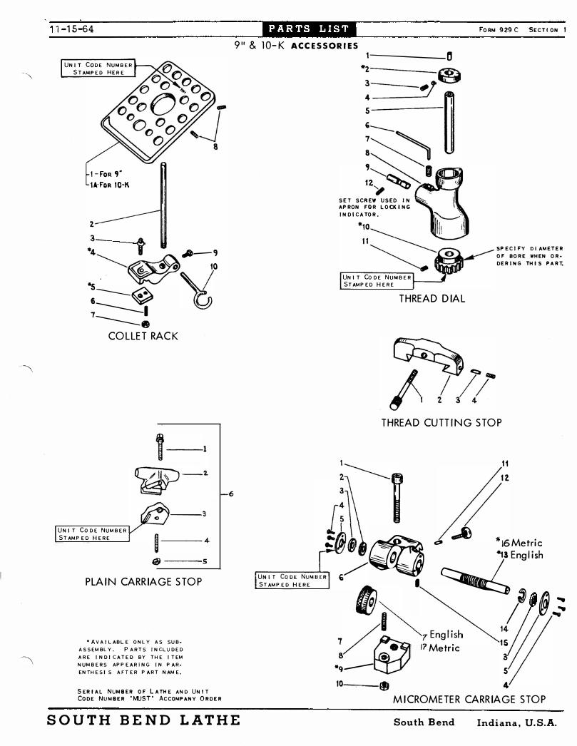
1-15-64 FORM 929 C SECT! ON 1
9" & lO-K ACCESSORIES
UNIT CODE NUMBER S TAMPED HER E
l-FoR ,. lA-FoR 10·K
2
.!- t �-9 �� I.
�--� � 7-----=. ----e
COLLET RACK
UNIT CODE NUMBER STAMPED HERE
f----3
1- 4. qj ----5
PLAIN CARRIAGE STOP
"AVAILABLE ONLY AS SUB. ASSEMBLY. PARTS INCLUDED ARE I NDI CATEO BY THE ITEM NUMBERS APPEARING IN PAR· ENTHESI S AFTER PART NAME.
SERIAL NUMBER OF LATHE AND UNIT CODE NUMBER 'MUST' ACCOMPANY ORDER
SOUTH BEND LATHE
-----0 *2---___ @j !_= __ �t#l I 5
�� f�� ,,�
SET SCREW USED IN AP RON FOR LOCK! NG
INDICATOR.
UNIT CoDE NUMBER STAMPED HERE t---....3'
THREAD DIAL
SP ECIFY DIAMETER
OF BORE WHEN OR·
DERING THI S PART.
THREAD CUTTING STOP
1 11
:�� f/" �!\ -AU ... � �_ � '110 16Metric /��:o-. - �.13EngliSh
r"U-N-I-T -C=-O-O-E-,N,,-U-M-B ..... E-.R 6
• STAMP ED HERE
�� ) @.:� /�'� �7English 14/;/ 7/ I.. 17Metric 15 8 . 3
*q-- 5 10-__ � 4
MICROMETER CARRIAGE STOP
South Bend Indiana. U. S.A.

·��'I�Ii� 11-15-64 911 & lo-K MICROMETER CARRIAGE STOP
911 & 1D-K COLLET RACK
ITEM PART NAME PART NO.
ITEM PART NAME PART NO.
NO. NO.
1 CAP ::'CREW 114 X 124 I COLLET RACK PT780N2 2 FEL T WASHER PTI 207NT l IA COLLET RACK PT780KR2 3 BUSHING PTI206NTI 2 RACK PIP E PT497� I 4 PHILL IP SCREW 104 X 206 3 CoLL AR SCR E W PT371NKI 5 COVER PLATE PT1209NTI 4 BRACKET (3··5·9) • A S7 82NK 1 6 MICROMETER STOP FRAME 5 CLAMP (6.7) ·AS863NR 1 "7 ORDER ITEM 13 PT1203NT2 6 SET SCREW 12 2 X 624
8 SET SCREW 1 22 X 520 7 JAM NUT 137 X 25 9 CL AMP ( 8· 10) *ASI201NKI
8 SET SCREW 12 2 X 005 10 J AM NUT 137 X 23 9 SQUARE HD. SET SCREW 118 X 108
11 SHOE PTlOA3NTI 10 DRAW BAR HOOK PT781NR Be TI
12 LOCK SCREW PTI204'lT2
13 SHAFT (7) Engl ish I· A S I 20 2M< 2
14 FEL T WASHER .· SLOTTED PTI208NTI
15 K EY PTI210NHI
16 Shaft ( 1 7) Metric PT227 1 NK 1 17 Order Item 1 6
9" & 1D-K THREAD DIAL I 9" & lO-K PLAIN CARRIAGE STOP J ITEM
PART NAME PART NO. NO. ITEM
PART NAME PART NO. NO.
I OILER 155 X 16
2 INDICATOR DIAL (3·4) ·AS888NK 2 1 Collar Screw PT2 1ONK2 3 SET SCREW 122 x903
4 SHOE PTI078N K I 2 Stop PT 1 489NK 1 5 INDICATOR SHAFT PT89INK2
6 WRENCH CE2392
7 SET SCREW 120 X 6
3 Clamp PT 1 20 1 NK 1 4 Set Screw 1 22 x 520
8 INDI CATOR FRAME 5 Hex Nut 137 x 23 9 MOUN T1NG STUD PT889NK I
1O WORM WHEEL (II) • AS887NR2 6 Complete Unit CL758NK l II SET SCREW 120 X 6
12 SET SCREW 120 X 6
9" & 1D-K THREAD CUTTING STOP I ITEM
PART NAME PART NO. NO.
I SCREW PT24�t<1
2 THO. CUTT I NG STOP PT67NK 1
3 BINDER PLUG PT418NK I
4 SET SCREW 122 X 606
SOUTH BEND LATHE South Bend Indiana, U. S.A.

F O R M 9 49 B S E C T I O N 1
I TEM N O .
67
� J
7 1
7 2
7 3
7 4
7 5
76
77
78
79
SO
S I
63
76
PART PART N AM E NO .
P T38 1 N H I O I L P L U G S C R EW
• AS 1 5NK 1 B U L L G E A R ( 6 9 - 70 )
P T3 6 7N R I SP R I N G
P T2 1 4N R 2 P L U N G E R
P T200N 2 SP I N DL E
P T370K 1 P R O T E C T I N G R I N G
Q 2 1 7 5NK F A C E P L A T E 5 1I s -
Q 20 5NK SP I N D L E S L EE V E
CE2 40 1 C E N T E R
P T38 2NK 1 S C R E W
PT2090 K E Y
• AS4 3 2 N K 1 CON E ( 67 - 7 9 - 80 )
1 6 0 X 2 3 P I N P T4 3 3NK 1 .. V ". CON E P I N I ON
P T 2 58 9 NK I BU S H I N G
' AV A I L A BL E O N L Y A S S U B A S S EM BL Y . P A R TS I N C L U D E D A R E I N D I CA T E D B Y TH E I T EM N UM B E R S AP P EA R I N G I N P A R E N TH E S I S A F T E R P A R T N A M E .
64
0 . 0
" SP I NDL E A SS EMBLY
7ft 80
SOUTH BEND L ATHE
P A R T S L I S T 1 1 -15-64
9" UNDERD R I V E H EADSTOC K W I TH S L E E V E B E A R I N G S
M O D EL A . B . O R C
S E R I AL NUM B E R O F L A TH E A N D UN I T C O D E N U M B E R 'MU S T ' A C CO M P A N Y O R D E R
*62 . R E V E R S E B R A C K E T AS S EM B L Y I N CL U D E S Al l P A R TS S H O W N A BO V E
REVERS E BRACK E T A S S EMBLY
r
South Bend Indiana, U. S. A.

S E R I A L N UM B E R O F L A TH E AN O UN I T CO D E N U M B E R ' MUS T ' ACCO M P A N Y O R D E R
9" UNOERDR I VE H EADSTOCK W I TH S L E EV E B E A R I N G S
MO D E L A , B , O R C
1 / 2 *3
�� �� a � / , *6 } a BACK GEAR AS SEMBLY � D /
12 i 13 81 �
~ .. 1 5
" '20 I � " 11 1_12 13
Cl
�� 9 _ .. • � ��� - - " }' it?? CODE
NUMBER STM1PED
HERE
/ � « l\\ \ ' < ��: 7.7 28 / I � .. 2� �--::::-10 '2.7./�31_��\ 35- , i 33 34
I 36 � /37 381®\ �� 36
" AV A I L A BL E ON L Y A S S U B · A S S EM B L Y . P A R TS I N CL U D ED A R E I N D I C A T E D BY TH E I T EM N U M B E R S A P P E A R I N G I N P A R · EN TH E S I S A F T E R P A R T N AM E ,
SOUTH B END L ATHE
I TEM P A RT NO. NO .
l G 8 X 3 1 2
2 PT2 4 NK 2
3 * AS36 1 NK 2
4 P T l 1 5 1N l
5 P T376NK I
6
• AS 20 2NK I
7 1 6 6 X3 1 0
8 P T4 3 6NK I
9 PT2 5 7 6NK2
10 * AS2 56 3NK 1
I I 1 32 X I
1 2 1 1 4 X 2 20
1 3 AS 373KH2
1 4 1 8 3 X l0 3
1 5 P T 1 1 6 5RH I
1 6 1 2 2 X I 0 6
1 7 PT 1 080NK I
1 8 PT387NK 1
1 9 P T52 3K 2
20 • AS 5 1 2l( I
2 1 P T2 56 6NK I
2 2 • AS 5 1 2l( I
23 P T 524K 2
24 P T 107 SNR 1
2 5 P T374NR I
26 1 1 2 X I I 1 2
27 P T2676NK I
28 P T2 575NK 4
29 P T 36 6 K I
30 P T 36 9< 1
3 1 1 39 X26
32 P T3 77N R I
3 3 P T3 6 4K I
3 4 P T36 3K 1
3 5 P T36 5/11K 1
3 6 P TI 6 7 2NK I
37 1 38 X27
38 1 1 2 X 246
39
40 1 37 X 29
4 1 P T28NK 1
4 2 2 56 X l
4 3 • • • • • • • • • • • •
44 P T2 7 K 3 2f'.1< I 4 5 2 56 X 1 4
46
* AXS6 3 5K 2
6 3 · A S2 SNK I
6 4 P T 26NK 1
6 5 P T 207NK I
6 6 " A S I 4NK 1
CON T I N U E D O N
South Bend
6
B A C K GE A R S ( 4 . 5 )
S C R E W WASH E R E C C E N TR I C S H A F T
( I · 2· 7 · 6 )
TAP E R P I N O R D E R I T EM 6
CO N E C O V E R CAU T I O N P L A T E ( 1 t l D R I V E S C R E W
CAP S C R E W
CA P I L L A RY 0 I L E R
WASH E R
SC R EW H I N G E S C R . L O C K S C R .
S H O E R U B B E R BUMP E R
E XP A N D E R ( SM A L L )
SMA L L B E A R I N G ( 1 3 · 1 4. 1 5· 1 9 . 2 9 · 30 )
GU A R D H I N G E S C R E W L A R G E B E AR I N G
( 1 3· 14. 1 5· 2 3 · 3 3 · 3 4 )
E XP A N D E R ( L A R G E ) S H O E SP R I N G S C R EW O I L E R U, 0, HE A DS TOCK SOL I D SH I M ( SMAL L ) L AM I N A T E D SH I M ( SMA L L )
N U T S TOP SC R E W
SOL I D SH I M ( L A R G E ) L AM I N A T E D S H I M ( L A P '
CLAMP I N G STUD WASH E R
N U T S C R EW
N U T R E V E R S E Go R F E L T WI CK
TW I N G E A R F EL T WI C K R E V E R S E B R A C K E T
( 4 5· 53· * 60 )
N U T F EL T WI C K R E V E R S E S H A F T ( 40 )
L O C K B U S H I N G SNAP R I N G TW I N G E A R S TUD
( 4 2 · 47 )
O I L E R
P I N B U S H I N G SP R I N G
P L U N G E R K N O B P L U G
K E Y
R E V E R S E P L UN G E R ( 5 4 · 55· ·56· 57 · 6 1 )
P I N
R E V . B R A CK E T AS S EM B L Y ( 4 1 · 44 · · 4 6 · 4B · · 49 · 50
5 1 . · 5 2· 58 . 59 )
TA K E UP N U T ( 6 4 · 7 6 )
TA K E U P WA S H E R TH R U S T B E A R I N G
CO N E ( 6 7 )
V E R S E S I D E
Indiana, U. S.A.
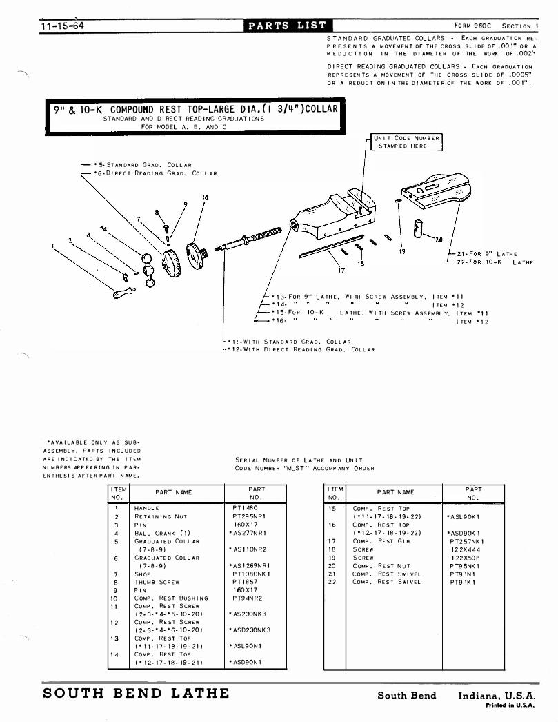
) ) 11 -15-64
S T A N D A R D G RADUATED COLLARS EACH GRADUA TION REP R E S E N T S A MOVEMENT OF THE CROS S S l i DE OF . 00 1 " OR A R E D U C T I O N IN THE D I AMETER O F THE WORK OF . 002"
D I R E CT READ I NG GRADUATED COL L A R S - EACH GRAD UATION REPRESENTS A MOVEMENT OF THE CROSS SL I DE OF . 0005"
OR A RED UCTION IN THE D I AMETER OF THE WORK OF . 00 1" .
9 " & l O- K COMPOUND REST TOP-LARGE DIA . (I 3/�" ) COLLAR STANDARD AND D I RECT R EAD I NG GRADUAT I ON S
FOR MODEL A . B . AND C
* 5- ST ANDARD GRAD . COL LAR * 6 - D I RE C T RE A D IN G G R AD. CO L L A R
" A VA IL A BL E ONL Y A S S UBASS EMBL Y . PARTS INCL UDED ARE I NO I CATED BY T H E I T EM
NUMBERS APPEA R I NG I N PARENT HESIS A FTER PART NAME.
I TEM PART N AME NO .
I HANDL E 2 RETA I N I NG N U T
3 P I N 4 BALL CRANK ( I l
5 GRA D UA TED COL L AR ( 7 - 8 - 9 )
6 GRAD UATED COL L AR ( 7 - 8 - 9 )
7 SHOE 8 T H UMB SCREW 9 P IN
1 0 COMPo REST BUS HING I I COMP o RES T SCREW
( 2 - 3- * 4- " 5 - 10 - 20 )
1 2 COMPo REST SCREW ( 2 - 3 - * 4 - * 6 - 1 0 - 20 )
1 3 COMP. REST Top
( " 1 1 - 1 7 - I S - 1 9 - ? 1 )
1 4 COMPo REST Top
( * 1 2- 1 7 - 1 8 - 19 - 2 1 )
UNI T CODE N UMBER STAMPED HERE
"
* 1 3- FOR 9"' L A THE. WI TH SCREW AS SEMBLY . I TEM ' I I
* 1 4- " I TEM " 1 2
9"' L A THE 1 0 - K L A THE
" 1 5 - Fo R 1 0 - K
" 1 6 - " ' L A THE . WITH SCREW ASS EMBLY. I TEM " I I
I TEM " 1 2
" " · WIT H STAND ARD GRA D . COLL AR * 1 2 - W I T H 0 1 RECT READING GRA D . CoLL AR
SERIAL N UMBER OF L A T HE AND UN I T CODE NUMBER "MUST " ACCOMPANY ORDER
PART I TEM N O . NO .
P T I 480 1 5 COMPo
P ART NAME
REST TOp P T29 5N R I ( * 1 1 - 1 7 - 18 - 1 9 - 2 2 )
1 60 X 1 7 1 6 COMPo RES T TOp * AS277N R I ( " 1 2.- 1 7 - 1 8 - 1 9 - 22 )
1 7 COMPo REST GIB " AS I I ON R 2 1 8 SCREW
1 9 SCREW 'AS 1 269N R I 20 COMPo REST NUT
P T I OSONK I 21 COMPo RES T Sw I VEL P T I 8 57 2 2 COMPo RES T SWIVEL 1 60 X I 7
P T9 4N R 2
* AS 2 30N K 3
, ASD230N K 3
* ASL90N I
* ASD90N 1
P ART
NO .
* A SL 9 0K 1
" ASD90K 1
P T2 57NK 1
1 2 2X 4 4 4
1 22 X 50 8
P T9 5NK 1
P T9 1 N l
PT9 1 K 1
SOUTH BEND LATHE South Bend Indiana. U. S. A. Prin .... in U.S.A.

FO RM 960C S E C T I ON
S TANDARD GRADUATED COLL ARS • EA C H G R A D U A T I O N REP R E S E N T S A MO V E M E N T O F T H E C R O S S SL I D E O F . OO I " O R A RE OU C T I ON I N THE O I A M E T E R O F TH E W O R K O F . 00 2" .
D I R ECT R E AD I NG GRADUATED COll ARS •
E A C H G R A DU A T I O N R EP R E S E N TS A M O V E · M E N T O F TH E C R O S S S L I D E O F . 000 5"
O R A R E D U C T I O N IN TH E 01 AME T E R O F TH E W O R K O F . 00 1 " .
' 1 4· Fo R MOO EL A � B W I TH S T A N D A R D G R A D . COL L A R . W I T H O U T TAP E R A T T .
" 1 5 · ..
" 1 6 · ..
* 1 7 · ..
° 6 · S T A N D A R D G R AD . CO L L A R
D I R . R D G .
. . · W I T H TAP E R AT T .
.. · W I TH O U T TAP E R A T T .
.. . W I TH TAP E R AT T .
1 1-1 5-64
Top V I E W O F S A DDL E SHOW I N G
l OC A T I ON OF CO D E N UM B E R
21 Z1
/ r
� lFO R l A T H E W I TH
TAP E R A T T .
* 2 4 · Fo R M O D E L C W I T H S TAN D A R D G R A D . CO L L A R · W I TH O U T TAP E R A T T •
S E R I A L N U M B E R O F l A TH E A N D UN I T CO D E N U M B E R " MJST " A C COMP A N Y O R D E R
" 25 · ..
* 2 6 · ..
" 27 · ..
9 " & lO-K CROSS FEED SCR EW-LARGE D I A . ( I 3/�" ) COLLAR
I TEM
NO . 1
2
3
4
5
6
7
8
9
10
I I 1 2
1 3
1 4
1 5
1 6
1 7
1 8
STANDARD AND D I RECT R EAD I NG GRADUAT I ONS
FOR MODEL A , B , AND C
PART NPME
S TU D
H A N DL E
R E TA I N I N G N U T
P I N B A L L C R A N K ( 1 · 2 )
G R A D U A T E D CO L L A R ( 8 · 9 · 1 0 )
G R A D U A T E D CO L L A R ( 8 · 9 · 1 0 )
SHO E THUM B S C R EW P I N
C . F . SL E E V E B E A R I N G CRO S S F E E D BUSH I N G CRO S S F E E O S C R E W ( 3 . 4 . ° 5 . " 6 . 1 1 . 1 2. 1 3 .
* 1 9 · 23 )
C R O S S F E E D S C R E W ( 3· 4 . " 5· * 6 · 1 1 · 1 2 · 1 3 ·
2 1 · 2 2 · 23 )
C R O S S F E E D SC R E W
( 3 · 4 · * 5 · " 7 · I I · 1 2· 1 3 ·
" 1 9 · 2 3 )
C R O S S F E E O S C R E W
( 3 · 4 · * 5 · " 7 · 1 1 . 1 2 · 1 3 .
2 1 · 22 · 2 3 )
P IN
P ART
NO .
P T I 2 4 1
PT I 4 9 1
PT29 5N R I
1 6 0X 1 7
° AS 1 2 6 4NK 1
• AS64NK 2
' AS 1 26 6 NK 2
P T 1 080NK l
P T 1 8 57
1 60X 1 6
P T6 9 R I AS84 I R I
PT63NK 3
" AS2 2 4N K 4
" ATA2 2 4NK 4
" ASD 2 2 4NK 4
" ADTA 2 2 4N K 4
PT3 58NK I
I TEM
NO .
1 9
20
2 1
22
2 3
24
2 5
26
2 7
SOUTH BEND LATHE
P AR T N N>1E
CRO S S F E E D N U T ( 1 8 · 20
S C R E W C RO S S F E E O N U T S C R E W
P I N
C R O S S F E E D S C R E W ( 3 · 4 · ' 5· ' 6 · 1 1 · 1 2 · 1 3 ·
• 1 9 · 23 )
CR O S S F E E D S C R E W ( 3· 4· ' 5· * 6 · " . 1 2 · 1 3 ·
2 1 · 2 2· 2 3 )
CRO S S F E E O S C R E W
( 3· 4 · " 5 · " 7 · 1 1 · I 2· I 3 ·
" 1 9 · 2 3 ) CRO S S F E E D S C R E W ( 3· 4 · ' 5 · " 7 · 1 1 · 1 2 · 1 3 ·
2.1 · 22 · 2 3 )
D I R . R D G .
PART
NO .
• AS6 5NK I
PT359NK I
PT486NK 1
PT66NK I
1 60X247
" AS 2 2 4J NK 4
" ATA224JNK 4
" ASD224JNK 4
" ADTA2 2 4JNK 4
• W I TH TAP E R A T T . . W I TH O U T TAP E R A T T . · W I TH TAP E R A T T .
" A VA I L A BL E O N L Y AS S U B · A S S EM B L Y . P A R T S I N C L U D E D A R E I N D I C A T E D B Y TH E I T EM N U M B E R S A P P E A R I N G IN P A R · EN TH E S I S A F T E R P A R T N A M E .
South Bend Indiana, U. S.A. Prin .... in U.S.A.

4-5-65
2 7 T H R E A D S P E R FORM 96 8 S ECT! ON
I N C H It i s possible to c ut 27 threads per inc h on any South Bend Lathe by procuring an
additiona l gear . Our pre sent 9" and Light Ten Model s B & C La the s and 10" -1" Colle t
Lathe s with wide range gear box are already equipped to cut 27 threads . For other
South Bend Lathe s see list below:
SIZE AND TYPE OF lATHE
DOUBLE TUMBLER GEAR BOXES
9" & Lt . 10 , Model A , Double Tumbler .
10" ( 11/16 or 1 " Col . Cap . ) Double Tumbler
13" Double Tumbler
14!-" , 16" 16-24" & 2H Double Tumbler
PfL"RT NO .
PT32K42NKl
PT32K42Rl
PT612K32Tl
For Gear Box Code No . Q . C .G . 103 • • • PT612K32FH2
For Gear Box Code No . D .T . G . 104 • • . PT612K32FH3
SINGLE WMBLER GEAR BOXES
10" ( 11/16 or 1 " Col . Cap . ) Single 'fumbler
13" Single Tumbler
l 4!-" , 16" , 16-24" & 2H Single Tumbler
SEE REVERSE SIDE FOR SET-UP CHART
PT612K32Rl
PT6l2K24Tl
PT6l2K24FHl
IMPORTANT . When ordering you must specify "Gear i s to be used to cut 27 threads
per inc h . " Also state serial number of your lathe which i s stamped on flat way
of bed at tailstock end a nd gear box code number stamped on face of tumbler guide
bar attached to bottom of gear box . Thi s information enables us to double check
and to determine if correct gear i s being ordered .
SOUTH B END LATHE South Bend Indiana. U. S.A.

FOR\1 96 8 3
SET-UP CHART FOR CUTTING 27 THREADS PER INCH
{9" & Lt . 10 require s 20 Tooth Gea r . Furni shed With Lathe Stud 10" ( 1� ' Col . ) require s 20 Tooth Gear . Furnished With Lathe Gear 1 3 " require s 32 Tooth Spec ial Gear , PT612K32Tl
14-?f , 16" , 16-24" & 2H require s 32 Tooth Spec ial Gear . Use PT612K32FH2 Gear on lathe s with Gear Bo� Code QCGI03 . For lathe s with Gear Box Code DTGI04 u se PT612K32FH3 Gear
Left Stud Gear Hand Threads Per Inch
Tumbler
A
A
See B Note
Above C 27
D E
Gear 13" require s 64 Tooth Gear . Furni shed On Lathe
{9" & Lt . 10 require s 42 Tooth Special Gear , PT32K42NKl Gear Box 10" ( 1" Col . ) require s 42 Tooth Spec ial Gear , PT32K42Rl
14tH , 16" , 16-24 and 2H require s 64 ?:,ooth Gear . Furni shed On Lathe
SINGLE TUlvtBLER GEAR BOX
st d{lOIt Lathe require s 32 Tooth Spec ial Gear , PT612K32Rl
Ge�r 13" Lathe require s 24 Tooth Special Gear , PT612K24Tl 14�" , 16" , 16-24 and 2H Lathe s require s 24 Tooth Spec ial Gear , PT612K24FHl
Sliding Top Gear Lever
Left
In Center
Right
Left
Out Center
Right
: 27
." ..
Threads Per Inc h
� � � � � � � � � � � � SOUTH BEND L ATHE South Bend Indiana, U� S.A.

-\
F S E C T I ON 1
TO MOUNT A,,!O ADJUST, 9" & lOK END GEAR GUARD
Hinge Eccentric
Spacers --...... ;;;;;;J.t
Spind l e hole i n guard
End Gr . Guard
Set screw "B "
Bracket
Hex . Nut (2 Req . )
Set screw "A "
1 . Insta l l bracket on bed and secure in p lace . On horizonta l lathes set bracket near end of bed . On underdr ive lathes set bracket approximate l y 1/4" back from end of bed . Tighten set screw "A " .
2 . Place eccentric in guard and mount i n bracket wi th spacers
3 .
4 .
5 .
6 .
7 .
8 .
between guard and bracket . ( See fig . above) Use any combination of spacers requi red for proper c l earance between spi nd le end and hole in guard .
NOTE: Spacers of varied thicknesses are supp l ied for the purpose of using any combination to obta in proper insta l lation .
Insta l l one hex nut on end of h inge eccentric j ust enough to a l l ow the second one to be i nsta l l ed .
Insta l l second hex nut an� lock with first . Adj ust the guard right or J�ft by turni ng the eccentric by the l ocked nuts w i th a wrench'.; Secure eccentri,,\ by tightening set screw " B " .
"'> Unlock nuts and turn one up aga inst bracket tight enough to keep guard c losed but l oose enough to swing open by hand .
L ock with second nut . NOTE: New mach ines have h inges tightened to keep guard c l osed during transit . It may be necessary to l oosen hex nuts s l ight l y and re lock to a l l ow guard to open easier .
4-5-65
SOUTH BEND LATHE South Bend , Indiana. U. S.A. Printed in U.S.A.

4-5-65
� 1 0 �
� For Al l 9 11 �@it 1 2 __ � � ----, <§:> For 1 0 K B C
Horizontal Drive
------------,-;.-� -. T I O N 1
D- 24 \. (6 � Fo�2;:: B t *7 - For 9 11 & 1 0 K C *8 - For 9 " & 1 0 K B C Metric
15 _____ L * 1 3 -f'For 9 11 & 1 0K ABC S E R I AL NUM B E R O F L A TH E �UST' A CCOMP A N Y O R D E R � �
1 6�®
LEor 9 " & 1 O,K A Metric * 1 4 - For 9 11 & 1 0 K B C Metric
'--* 1 7 For 9 " & 1 0K A Underneath Drive For 9 " & 1 0 K A Underneath Drive Metric
COMPLETE ASSEMBLY AS S HOWN * 1 8 For 9 " & 1 0 K B Underneath Drive TO I NCLUDE GUARD, H I N GE EC- I---------i CE NTRIC BRACKET, AND ALL
* 1 9 For 9 " & 10K C Underneath Drive *20 For 9 " A Horizonta l Drive
HARDWARE F ITT I N GS REQU I RE D .
' AV A I L A B L E ON L Y A S S U B - A S S E M BL Y . P A R T S I N C L U D E D A RE I ND I C A T E D B Y TH E I T EM NU M B E R S AP P E A R I N G I N P A R E N TH E S I S A F T E R
P A R T N A M E .
ITEM PART NO . PART NAME NO . N O . REQ .
1 PT l 45 N Kl Eccentric 1 2 PTI46N2 Guard 1 3 PT650N K2 Guard 1 4 PT906N K2 Guard 1 5 1 30 x 1 03 Drive Screws 4 . 6 *AS I525 N K2 Index Plate (5) 1 7 *AS I527J NRI Index Plate (5) 1 8 *AS I 529 N R2 Index Plate (5) 1 9 PT648K l Spacer 1
1 0 1 6 1 x 27 Finished Washer 1 1 1 1 61 x 65 Finished Washer 2 1 2 1 20 x 1 06 Set Screw 1 1 3 *AS 1 47 N K3 Brocket ( 1 2 , 1 5) 1 1 4 *AS907N K3 Brocket ( 1 2 , 1 5) 1 1 5 1 1 8 x 2 1 4 Set Screw 1
SOUTH BEND LATHE
For 9 " A Horizonta l Drive Metric
*2 1 For 9" B Horizonta l Drive *22 For 9 " C Horizonta l Drive
�*23 For 9 " & 1 0K B C Horizonta l Drive Metric
ITEM PART NO . PART NAME NO . NO REQ . 1 6 1 39 x 3 1 Hex Nuts 2 1 7 *AS650N K2A Guard Assembl y
( 1 , 3, 9, 1 0, 1 1 , 1 3, 1 6) 1 8 *AS650N K2B Guard Assembl y
( 1 , 3, 6, 9, 1 0, 1 1 , 1 3, 1 6) 1 9 *AS650N K2 C Guard Assembl y
( 1 , 3, 7, 9, 1 0, 1 1 , 1 3, 1 6) 20 *AS 1 46N2A Guard Assembl y
( 1 , 2, 9, 1 0, 1 1 , 1 3, 1 6) 2 1 *AS I 46N2B Guard Assembly
( 1 ,2, 6, 9, 1 0, 1 1 , 1 3, 1 6) 22 *AS l 46N2C Guard Assembl y
( 1 , 2, 7, 9, 1 0, 1 1 , 1 3, 1 6) 23 *AS906N K2 Guard Assembl y
( 1 , 4, 8, 9, 1 0, 1 1 , 14 � 1 6) 24 *AS441 -3 Lubrication Plate (5)
South Bend Indiana, U. S.A. Printed i n U.S.A.
'--

_--- Ins truction for j oining types VT , Vv � COLD JOINING on South Bend wthes . i
( 1)
( 2 ) ( 3) ( 4 )
( 5)
Materia18 required . '
RAPPLON be lt with prepared
RAPPLON llSNAX.. 1 bOttl •• .. , '"
f
. . . . ' . "
ku.fih for applying 11'S MAE " I pie<i:.. . . • . " . . . .. •• . . .. . , }- " ' ; ;; " ':' ; ':�:'/ ' : " ,: : --;; . , .',,:
-" - -;: -- >:' ..
Plat.s stee ,l , perfectly tla.t , app��. ;.�·� .i� approx. S· x 5· , l piec.. .
'
c - clamp. . .......... BE Q.REFUL NOT TO SPI � ANY ,118 NAlt S CONTACT, FWSH lHMEOIATELY WITH WATER . WEAR P'Dt'VY'1:'1""
Installation proCedure ot RAPPLCN be lts .
1 . ', .
2
. . . ,,� .. ... -:.; . . . .. . � .,.� .. " ... . �.:,� . . � ... ��\" ,,,, . " , , ' . . . , " .
•
I
Put belt around pulleya . """, ' Jlemove plastic wrappint tr9Di prepared
.ods , pt RAPPLCN be�t •. , Make sure you ' do not make ends w.;$ <* greasy . po' b'Qt touch preparetf ends with 91� •
� ,'� . 'tbi�o,�l.�r �t ,glue llSNAK ov�r J.�; . �re ... ( see picture 1) ;� _ ... . tt:�, .f()r 2 to 3 mi nute� .
- ' Put both ends of be lt between the two steel plate s . Make sure that both l ines on be lt match exactly . ( Ny lon to Ny l on and V-cove r to V- cove r)
P re s s ends together between ' stee l 'plate s u s ing C-Cl amps . Do not press on one s i de more , than on . other t , to avoid any d i splacing of belt between plateslo
LET 8ELT SET BETWEEN STEEL P LATES UNDER �RESSURE F� \'
8 HOURS Take be lt out, o f the cl amping devi ce , clean edg es wi th s anding paper and tension belt according to ins tructions enclosed .
Leder Inc. Carmichaels PA 1 5 3 2 0 L ED' ID 052 Browns F.rry Ro.d T.'. 14 1 21 966 f I"l 8 4 T.lex 2 9 19 4 0 l.t�J� 1ft USA

BELT CARE AND MAINTENANCE · SUGGESTIONS
1. Keep flat belt clean. Remember, belts wear out. They cost little. Use the recommended Flat Belt and replace as frequently as necessary.
2. Maintain proper belt tension.
3. Do not run Lathe with too much tension on belt. This may result in loss of power, excessive bearing wear, causes motor to run hot, and abnormal stretching of flat belt.
4. Release belt tension lever, taking strain off belt when Lathe is not operating.
5. Routine checking and adjustment of the belt tension, according to instructions, will keep Lathe efficiency high and repair expenses low.
6. When ultimate of belt tension adjustment has been reached, replace with new Flat Belt. Order the correct belt from your nearest South Bend Distributor or direct from our factory.
BELT ADJUSTMENTS
HORIZONTAL DRIVE LATHE
CONE PULLEY BELT-Belt tension releCIlle lever "C"
permits releCIlling cone pulley belt tension for aJ1lfting belt to change spindle speeds. Turnbuckle . "AU adjusts tension of the cone pulley flat belt. This adjustment must be made with lever "C" in running poaition.
MOTOR V-IELT-Screw "B" adjusts tension of the motor V-belts. Loosen all four bolts and move motor in slots until desired tension is obtained.
CROSS SECTION OF UNDERNEATH BELT MOTOR DRIVE
SHOWING CONE PULLEY BELT AND V-IELT
C leu
TENSION IEU'ASl
UVEa
A CON!
PULLEY liLT
ADJUST. MINT
B
A�:�N. MENT
Belts should be just tight enough to transmit the required power without slipping. Pressing the hand against a properly adjusted flat belt near the cone pulley should depreBS belt about !f.z". The V-belt, midway between pulley, should depress about !f.z". Belts may be cleaned with carbon tetrachloride or naphtha and the flat belt treated with neat's foot oil, if belt is dry and stiff.
FLA T BELT TENSION ADJUSTMENT (For Texolon B.I,. Only)
1. Adjust belt tension so belt is-just tight enough to remove any slack in the belt (without stretching).
2. Mark pencil lines on face of belt as shown at "A" and "B" exactly 25" apart.
3. Adjust belt tension forcing belt to stretch }{a" to VB" as shown at left. Check with rule (See belt tension adjustment instructions inside door). The above amount of belt stretch should provide sufficient belt tension for normal use.
'<'· " 1::" CHAIlT . (»$;14;"' ,
. . . . �. \
LU BRICATI ON CHARt FOR
.
NINE-INCH. 'AND 1 0-K LATHES M.ODELS A, B & C
HELPFUL SUGGESTIONS FOR THE PROPER MAINTENANCE OF YOUR LATHE WHICH WILL HELP TO PROLONG THE ORIGINAL
ACCURACY, ITS SERVICEABLE LlF,E !AND ITS EASE OF OPERATION.
SET .. UP PROCEDURE 1 . Look carefully i.n ql l packages for small parts, i nstruction
material, etc. 2. Study al l reference books and instruction sheets carefully. 3. Clean lathe thoroughly. 4. Do not move carriage until bed ways have been thor-
oughly cleaned and oiled. S. Mount on a substantial floor, preferably concrete. 6. Level lathe. (See i nstructions inside) 7. Lubricate lathe. (See lubrication chart inside)
OPERATIONAL MAINTENANCE 1 . Keep your lathe clean. 2. Keep your lathe lubricated as recommended. 3. Keep belts clean and properly adj usted at al l times. 4. When your lathe is setting idle keep it covered with one
of our service covers. Write for accessory catalog. S. Do not use an air hose to remove dirt or chips. Air pres
sure will force foreign matter into bearings, gears, etc., causing serious damage.
6. Recheck lathe leveling periodically.
$BL Inc I Precision Machine Tools Since 1906

L E V E L I N G T H E L A T H E The correct installation and leveling of the lathe is more important than is generally realized. Precision tolerances can be maintained only when the lathe is mounted on a solid foundation and properly leveled according to the following instructions.
FOR LATHES WITHOUT TAILSTOCK
LEVELING LEG SCREWS
1. Level bench and fasten to floor before mounting and leveling lathe.
2. Clean all dirt, chipe, etc.. from bed ways.
3. Place precision level squarely acroBB V-ways at "A". (Use South Bend 12" Precision Level, Cat. No. CE221S, or equal.)
4. Drive shims· under headstock leg at "B" until bubble on the level is approximately central. Carefully note the exact position of the bubble in relation to graduations on the level.
S. Move level and place squarely acrOBB V·ways at "C". Do not turn level end for end.
S. Drive shims· under leg at "0"' until bubble comes to rest at exactly the same position in relation to graduations as when level was at "A".
7. Repeal steps 2, 3. 4, and 5. until level readings at "A" and "'C" are identical.
S. Fasten legs at "B" and "D" only to bench.
9. Check again at "A" and "C" to see if level reading. have remained the same. U not, the leveling procedure must be repeated. THE LEVEL READINGS SHOULD BE EXACTLY AUKE AT "'A" AND "C" POSITIONS AFTER THE LATHE IS FASTENED TO THE BENCH. OTHERWISE THE LATHE WILL NOT TURN OR BORE ACCURATELY.
TO MAINTAIN ACCURACY CHECK LEVELING PERIODICALLY
South land 12" P_i.lon Level
• SHIMS-Should be made of metal or other material not affected by moisture or atmospheric conditions. Tapered steel shims are best. Wood shims are not desirable because of swelling, shrinking, etc., and eventually deteriorate.
LEVEL-Use a precision level of at least 12" in length and sufficiently sensitive to show a distinct movement of the bubble when a .003" llhim is placed under one end of the level. We recommend our 12" South Bend Precision Level Catalog No. CE22IS. Moderately priced, this level can be obtained immediately from your nearest South Bend Lathe Distributor or direct from out factory. Do not use a carpenter's or an ordinary machinist's level because they do not have sufficient sensitivity for leveling precision machine tools.
Expansion bolt In coner ....
La, scr.w in Machine bolt with wood floor. Javalin, scr_.
Methods of securing lathe to floor.
Machin. bolt .. t in m.lted sulphur.
FOR LATHES WITH TAILSTOCK LEVELING LEG SCREWS
1. Clean all dirt, chips. etc., from bed ways.
2. Drive shima' under each leg pad at "A" and "E" so lathe will set firmly on floor at all four points, removing any rocking motion under the legs.
3. Loosen the leveling leg screws at "B", both front and rear screws.
4. Place precision level squarely across V-way at "C" (Ulle South Bend 12" Precision Level Cat. No. CE221S or equal).
5. Adjust shima under leg pads at "A" until bubble on the level ill approximately central, carefully note the exact position of the bubble in relation to graduations on the level.
S. Without turning level end for end, move level and place squarely across V-wayl at "0".
7. Adjust shims under leg pads at "E" until bubble comes to reat at the same position as when level was at "C".
S. Repeat steps 4, 5, S, and 7, until level readings at "C" and "0" are approximately the lame.
9. Fasten to floor.
10. Adjust the Tailstock leg leveling screws at "B" until level readings at "C" and "0" are exactly the same. Then lock leveling screwi.
I I . CAUTION-THE LEVEL READINGS SHOULD BE EXACTLY AUKE AT BOTH POSITIONS AFTER THE LEGS ARE FASTENED TO THE FLOOR, OTHERWISE THE LATHE WILL NOT TURN OR BORE ACCURATELY.
A. B
TO REMOVE SPINDLE:
1. Remove gear guards "A" and "B".
2. Remove reverse bracket aBBembly "C".
3. Loosen binding screw in take-up nut "0". Remove nut "0" and washer "E" from spindle.
4. Drive out the spindle from headstock, using a lead or babbitt hammer, or a wooden block as shown at "F". Drive toward threaded end of spindle. When
INSTRUCTIONS FOR REMOVING HEADSTOCK SPINDLE, INSTALLING NEW V-BELT, AND REPLACING HEAD
STOCK SPINDLE ON 9" SOUTH BEND LATHE
thrust bearing, cone and bull gear will fall out, so be careful not to nick or damage these parts.
5. Install belt.
6. Place a piece of wire, "G", into bearing breather hole, to hold down the oil wickll, "H"', at both bearings.
TO REPLACE SPINDLE:
.j spindle is being removed from head, the
1. Reverse the procedure outlined above, taking care to preBB the bull gear onto the spindl�o not drive it on. Be very careful not to get dirt into bearings.
I
)

L U B R I C A T I lO-K L AT H E S , M
Oiling point for primary idler gear.
Drain and flush apron every 3 months.
Oiling points on Underneath motor drive lathes. Type "B"
Oil on countershaft. Oil Oiling points on Double Tool Cross Slide. TYPE "C" oil at
all points. Oil Dai
Oiling point on Handlever Type Collet Attachment. TYPE "C" oil. Keep Full.
Counter Shaft
Bearings TYPE OIL "B"
Keep Full
Reverse Bracket
TYPE OIL "C" Fill Daily
Idler Gear TYPE OIL "C"
Oil Daily
Gear Box TYPE OIL "B"
Fill Daily
Reverse Bracket
TYPE OIL "C"
Back Gears --f==3-"-T---Teflon Grease
Lubricant ROY DEAN #DE 1 1 2
Fill Daily ------
Oiling point on Thread Dial Indicator. TYPE "C" oil.
Oil Daily when used.
Oiling point on Micrometer Carriage Stop. TYPE "C" oil
Oil Daily when used.
Idler Gear TYPE OIL "C"
Oil Daily
Gear Box TYPE OIL "B"
Fill Daily
O i l ing D i rections as Ind icated are for
an 8 hr. shift. When used for longer
pe riods, each o p e r a t o r should oil
machine.
PUMP OIL CAN. Suitable for lubricatinq all types of machinery. Has large nonciOQqing pump tube. Cone tipped. spout seats in oil hole forces oil into "bearinQinqs and prevents spilling. Hook. on tip for opening spring cap oil cups. Holds :VB pint and has 6· spout.
CE351S. Pump Oil Can. Shipping weight llb.
ADDITIONAL COPIES OF THI S CHART
ON REQUEST - ASK FOR CHART 6 5 1 4
S6514-- LOXM--1 1 -65 Printed in U . S . A .
$BL Inc I south Bend Lathe 400 West Sample Street South Bend, Indiana 46625 Telephone: (21 9) 289-7771
C H A R T A , B & C
Apron Bearings
TYPE OIL "C" Oil Daily
Spindle Threads
TYPE OIL "C"
Apron Reservoir
TYPE OIL "A" Oil Monthly
, B & C Spindle Threads
TYPE OIL "C"
Apron Reservoir
TYPE OIL "A" Keep Full
Feed Screws TYPE OIL "C"
Oil Daily
Graduated Collars
TYPE OIL "C" Oil Daily
Graduated Collars
TYPE OIL "C" Oil Daily
Half Nuts TYPE OIL "C"
Oil Daily
Tailstock TYPE OIL "C"
Oil Daily
Half Nuts TYPE OIL "C"
Oil Daily
LUBRICATING OIL SPECIFICATIONS Machine Oil Sayboh Universal Viscasity Rating in Secands at 1000F.
Company Type A Type B Type C Name 100 Sec. 1 50-240 Sec. 250-500 Sec.
South Bend Qt. can-CE1600 Qt. can-CE1602 Qt. can-CE1603
Lathe Gal. can-CE2017 Gal. can-CE2018 Gal. can-CE2019
Contact your nearest South Bend Lathe Distributor or order oil
direct from factory at South Bend. Oils developed for auto
mobile crank case lubrication are not recommended for ma
chine tool l ubrication.
c 1965 South Bend Lathe . A l l rights reserved .


![US EPA, Pesticide Product Label, CDB CLEARON GRANULAR, 10 ...€¦ · f Pis fie read instructions on nvana baton comolatirx] form. Form Appfoved. OMB No. 2070-0060. Approval expires](https://static.fdocuments.in/doc/165x107/5eac91f3553f8b09b94f6716/us-epa-pesticide-product-label-cdb-clearon-granular-10-f-pis-fie-read-instructions.jpg)


![REPORT DOCUMENTATION PAGE R I READ INSTRUCTIONS … · REPORT DOCUMENTATION PAGE R I READ INSTRUCTIONS BEFORE COMPLETING FORM REPO147 NUMBL& 12 GOVf ACCESSION NO.1I ] RECIPIEN'rS](https://static.fdocuments.in/doc/165x107/5eb9d89eeaebac3c932c546b/report-documentation-page-r-i-read-instructions-report-documentation-page-r-i-read.jpg)