(Form No. 1798.) - Replica Plans Manuals/8inhowitzermanual.pdf · (Form No. 1798.) The Commanding...
61
Transcript of (Form No. 1798.) - Replica Plans Manuals/8inhowitzermanual.pdf · (Form No. 1798.) The Commanding...
(Form No. 1798.)
The Commanding Officer or the Post or Coast Defense Ordnance Officer to whom this copy is issued will be held personally responsible for its safe- keeping. When a~other officer relieves him a receipt for it will be taken, which should be mailed to the CHIEF OF ORDNANCE, U. S. Army, Washington, D. C.
NOTE.-This pamphlet may be destroyed when superseded by one of later date.
(2)
WAR DEPARTMENT, OFFICE OF THE CHIEF OF ORDNANCE,
Washington, January 15, 1918.
This manual is published for the information and government of the
Army of the United States. BY ORDER OF THE SECRETARY OF WAR:
C. B. WHEELER, Brigadier General, Ordnance, N. A., Acting Chief of Ordnance.
(S)
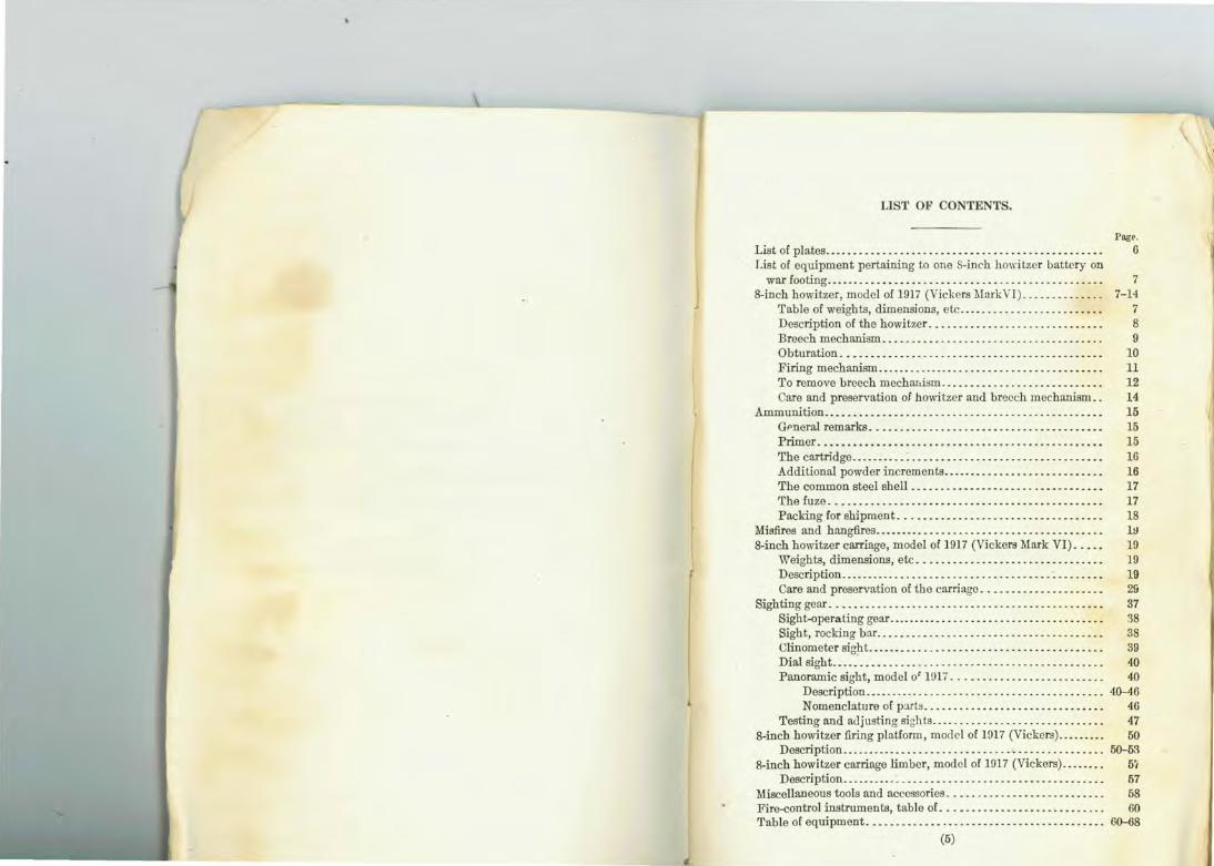
LIST OF CONTENTS.
List of plates ................ .... ........................... . List of equipment pertaining to one S-inch howitzer battery on
war footing ... _ ........ __ ................. .. .............. . 8-inch howitzer, model of 1917 (Vickers hi ark 1) . .... _ ... _ ... .
Table of weights, dimensions, etc ..... . .... ......... ..... . Description of the howitzer._ ......................... _._ Breech mechanism .............. .... ................... . Obturation ...... _ ........ .. ...... . ................ _ ... _ Firing mechanism ................. .. .................. _ .. To remove breech mechauism ......................... __ . Care and preservation of howitzer and breech mechanism ..
A=unition ......................... .... ... ... ............ . GPneral remarks ... _ .. _ ................................ _ Primer .......... _ .......... _ .. _ ..... _ .... _ ........ , ... . The cartridge ........................... _ ..... _ ...... _ .. . Additional powder increments._._ .... .. ................. . The common steel shell ................................ . The fuze .............................................. . Packing for shipment .................................. .
Misfires and hangfires .............. ... ...................... . 8-inch howitzer carriage, model of 1917 (Vickers Mark VI) .... .
Weights, dimensions, etc ............................... .
r
Description ................ . .... . ....................... . Care and preservation of the carriage ... ... .............. .
Sighting gear .............................................. . Sight-operating gear ............. ... ..................... . Sight, rocking bar ...................................... .
~:o:g~;~-~-~~~-------~:::::::: :::::::::::::::::::::::::::: Panoramic sight, model o' 1!J17 ... _ ..................... .
Description ......................................... . Nomenclature of p:uts .................... .. ........ .
Testing and adjusting sights ............................. . 8-incb howitzer firing platform, morlcl of 1917 (Vickers) ........ .
Description ............................................. . 8-inch howitzer carriage limber, model of 1917 (Vickers) ....... .
Description .............................. .. ............. . Miscellaneous tools and accessories .......................... . Fire-control instruments, table of ........................... . Table of equipment ........ . ....... . ....................... .
(5)
Page. 6
7 7-14
7 8 9
10 11 12 14 15 15 15 16 16 17 17 18 lll l!J 19 19 2& 37 38 38 39 40 40
40-46 46 47 50
50-53 5~
57 58 60
60-68
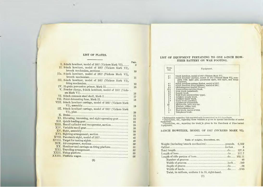
LIST OF PLATES.
I. 8-inch howitzer, model of 1917 (Vickers Mark VI) ..... II. 8-inch howitzer, model of 1917 (Vickers Mark VI),
breech mechanism, sections .................. _ .. . . IIA. 8-inch howitzer, model of 1917 (Vickers Mark VI),
breech mechanism ........ . .......... __ ... ____ .. . III. 8-inch howitzer, model of 1917 (Vickers Mark VI),
firing mechanism ... _ ....... _ .. __ . ___ . _ .. ____ .... . IV. 21-grain percussion primer, Mark II ........ ___ .. .... .. V. Powder charge, 8-inch howitzer, model of 1917 (Vick-
ers Mark VI) .................................... . VI. 8-inch common steel shell, Mark I. ................. ..
VII. Point detonating fuze, Mark II. ................ ... .. VIII. 8-inch howitzer carriage, model of 1917 (Vickers l\Iark
VI), assembly .................................... . IX. 8-inch howitzer carriage, model of 1917 (Vickers Mark
VI), plan ...................................... .. X. Brake .............................................. .
XI. Elevating, traversing, and sight-operating gear ........ . XII. Quick-loading gear ................................. ..
XIII. Recoil cylinder and recuperator, section ............. . XIV. Variable recoil gear ................................. . XV. Sight, assembly ......... ..... ........... . .... ...... .
XVI. Sighting arrangement, section .. ......... ..... ...... . XVII. Panoramic sight, model of 1017 ..................... .
XVIII. Target for testing sights .............................. . XIX. Air compressor, sections ............................ . XX. Howitzer and carriage on firing platform .............. .
XXI. Traveling arrangement .. .... . ...... ... .. ........... . XXII. Firing platform ... ........ .... ... .. ...... . ...... .. .. .
XXIII. Platform wagon ................... .... ........ ...... .
(6)
Page. 8
10
11
12 15
16 17 18
19
20 21 22 23 25 26 38 39 42 48 50 51 52 53 56
LIST OF EQUIPMENT PERTAINING TO ONE 8-INCH HOWITZER BATTERY ON WAR FOOTING.
Num- Equipment. bcr.
---4 I &-inch howitzer, model or 1917 (Vickers Mark VI). 4 I S.mch howitzer carria{!c, model or 1917 (Vickers Mark VI), com-
plete with sight gear, pnnqramic sight, dial sight, and range quadrant.
41 &-inch howitzer carriage limber, model of 1917. 41 &-inch howitzer firing platform, model or 1917. 4' 1.2{}-horswower tmctor (20-ton).
12' Atnmlllll iOD-{lllrrying truck. s• 3-ton truck ~erscnnel). 2• SupflY true . 2' Too truck (ammunition typo), 1• Artillery snpply truck. 1. Artillery repair truck. 1' Tank truck (gasoline). 3 5-fo=enger automobile.
12 1 otorcycle, with side car. I Kitchen, rollin!! trail. 1 Reconnaissance car. I l Reel trnck, motlcl of 1918. 1 'l'elephone truck.
1 Information regarding this materiel only' is contained in I h i> hand bonk. • Description, etc., regarding these vehicles_is gi\·cu ln specia l handbooks or motor
equipment. •Description, etc., regarding the truck:::is given in tile Handbook or Fire-Control
F.quipment.
8-INCH HOWITZER, MODEL OF 1917 (VICKERS MARK VI).
Table of weights, dimensions, etc.
Weight (including breech mechanism) ... ...... ...... pounds. Caliber_ .......................................... inches .. Totullength .... ... ..... - ............................ do ... . Length of bore ....................................... do . .. . Length of rifle portion of bore ......................... do . .. .
Number of grooves .................................... . Width of grooves ....... ......................... inch .. Depth of groove .................................. ao ... . Width oflands .................................. do ... . Twist, in calibers, uniform 1 in 15, right-hand.
(7)
G,552 8
127.G 117.7
102.11 48
.349 .06
.1745
s Powder chamber:
Diameter .. .......... •. .... . .. . ... •. ... .. ... . . inches .. Length ... . . ... . ... ...... . ....... . .... . .......... do ... . C'apacity .............. . .. .. .. .. .. . .. .. . cubic inches .. Total capacity of bore ........ ............. ... ... . do .. . .
Weight of projectile ..... .. . .......... ... .. . .. ..... . pounds .. Obturation ............................................... .
8.5 12.74
750 6,130
200 Pad.
Firing mechanism .... .. ...... . ...... .... ..... .. .. . .... Percueaion.
The principal difference between thelliark VI ho"~>itzer and the Mark VII howitzer is that the Mark VII howitzer is longer and heavier than the Mark VI howitzer. The Mark VII howitzer is wire wrapped, while the Mark VI howitzer is of built-up construction. The chamber capacity of the Mark VII howitzer is greater, thus giving a longer range. The principal ballistic differences are given in the following compamtiYe table.
I Mark VI.
Wcig!Jt of powder charge ... . ...... . ....... 10 pounds 12 ounces
Powdor charge, number or increments .... . (approximately).
4 Maximum muzzle vclocit y.fcetpcrs~conrl .. 1,300 Max1mum range .......... . ........ yards .. 10, 1;00
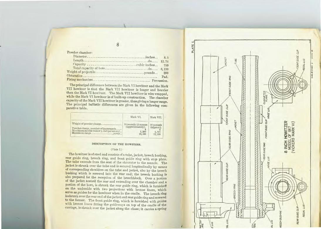
DESCRIPTION OF THE HOWITZER.
(Plate I. )
Mark vrr.
16pounds (approxJ.
1 52!; 12; 100
The howitzer is of steel and consists of a tube, jacket, breech bushing, rear guide ring, breech ring, and front guide ring with stop plate. The tube extends from the seat of the obturator to the muzzle . The jacket is shrunk over the tube and is secured longitudinally by means of corresponding shoulders on the tube and jacket, also by the breech bushing which is screwed into the rear end; the breech bushing is also prepared for the reception of the breechblock. Over a portion of the jacket toward the rear and extending over the chamber and a portion of the bore, is shrunk the rear guide ring, which is furnished on the underside with two projections with bronze liners, which serve as guides for the howitzer when i n the cradle. The breech ring is shrunk over the rear end of the jacket and rear guide ring and screwed to the former. The front guide ring, which is furnished with guides with bronze liners fitting the guideways on top of the cradle of the carriage, is shrunk over the jacket along the chase; it carries a spring
I'
~ ll u ~
f. ~ ~
IU 10
<.> ::;,
~ f.
~ § <> f.
~ Q:
<;),
d ...,
~ .... ~ 0:: ~ I.JJ > ~ Nr-x:
<> <> !::me:: .... s:-< ~ ~ ou..~ LJ J:~V) ~
J:WO:: <> uow ~ zox: "" -::E2
co >
~ ij ~ ~ ~ Q:
<;),
ct ~ LJ
~ ~ <> <!>
~ ~
..J Q:
~

9
plunger on the left side, which serves liB a reader for the recoil scale on the cradle. A steel stop plate is attached to the front face of the guides by four screwed rivets.
The breech ring is prepared for the reception of the breech mechanism and provided on the underside with a lug for •he attachment of the body of the hydraulic buffer and recuperator of the carriage. Securing screws are provided in the breech face to prevent the breech ring from turning when in position.
Right and left gun-metal dust covers with securing screws connect the front and rear guides.
The chamber is cylindrical, coned at the entrance and reduced in diameter at the front end. · A plane for a clinometer is prepared on the right upper side of the
breech ring. Axis lines are cut on the upper side and on the horizontal axis at
the breech and muzzle ends. Fine horizontal and vertical axis lines are also cut on the· breech and muzzle faces.
The actual weight of the howitzer (without breech mechanism) is engraved on top of the breech ring, and a line, denoting center of gravity (without mechanism), is cut transversely on the upper side of the jacket immediately in front of the rear guide ring.
The t ype, mark, register number, manufacturer's initials, and year of manufacture are engraved on the upper portion of the breech face.
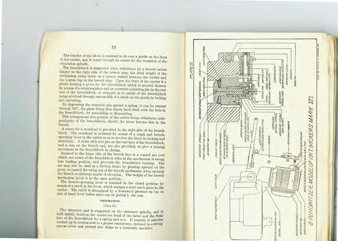
BREECH MECHANISM.
(Plato II and IIA.)
'The breechblock i s worked by means of an operating lever on the right side of the breech. On pulling the lever to the rear the breechblock is automatically unlocked and swung into the loading position. After loading, one thrust on the same lever inserts the breechblock and turns it into the locked position.
The breechblock is of the interrupted screw type. It is divided circumferentially into 12 equal parts, 4 of which are plain and the remaining 8 screw-threaded, thus giving a two-thirds bearing surface to the breechblock in the locked position. The threaded sectors are of different diameters, the breech recess of the howitzer having complementary threaded sectors to receive them. The interruptions in the howitzer are arranged to accommodate the sectors of the block of largest diameter ; thus, when the block is unlocked, these sectors pass into the interruptions and tho sectors smaller in diameter unlock into the spaces left vacant by those of the larger diameter.
10
The interior of the block is recessed to fit over a pintle on the front of the c:urier, and is bored through i ts center for the reception of the obturation spindle.
The breechblock is supported when withdrawn by a bronze carrier hinged to the right side of the breech ring, the dead weight of the mechanism being taken on a bronze washer between the carrier and the bottom lug on the breech ring. pon the front of the carrier is a pintle forming a pivot for the breechblock which is secured thereon by means of a retaining plate and an eccentric actuating pin in the rear end of the breechblock, so arranged as to admit of the breechblock being revolved through one-twelfth of a circle on the pintle in locking and unl0cking.
By depressing the eccentric pin against a spring, it can be rotated through 180°, the plate being thus drawn back flush with the hole ir the breechblock, for assembling or dismantling.
This arrangement also permits of the carrier being withdrawn independently of the breechblock, should the latter become fast in the breech.
A recess for a crosshead is provided in the right side of the breechblock. The crosshead is actuated by means of a crank and breechoperating lever in the carrier so as to revolve the block in locking and unlocking. A roller with axis pin on the rear face of the breechblock, and a cam on the breech end, are also provided, to give a turning movement to the breechblock in closing.
Secured to the hinge side of the breech face is a control arc over which one sector of the breechblock rides as the mechanism is swung into loading position, and prevents the breechblock rotating. The arc may. also be used as a friction brake by pressing upward on the rever, to control the swing out of the breech mechanism when opening the breech at different angles of elevation. The weight of the breech mechanism ho:Js it in the open position.
The breech-operating lever is retained in the closed position by means of a catch in the lever, which engages a steel catch plate in the carrier. The catch is disengaged by a downward pressure on lug on side of hand lever before same can be pulled k the rear.
OBTURATION.
(Plnte II.)
Tha obturator pad is supported on the obturator spindle, and is held tightly between the mushroom head of the latter and the front face of the breechblock by a spring and nut. It consists of asbestos worked up in mutton suet to a proper consistency, inclosed in a strong csnvas cover and pressed into shape in a hydraulic machine.
1::\ ~
" ~
r------------- - ---r-~i
' ' ' ' ' ' : ' '
' . ' ' ' : ------.L.. .. t
'--- -----------
~
~ ~ .,· ~ :\
~ .. ., "' "' ~
<(
~ ~ "C
ct ~
-:t~ ~
~ l iS~ !\: §"' ' \:;: ~~)<: ' '
~~ ' ~ \ "~<il
~ ~ !li
~ ~ ~~
" ~ s:~
~ ~~ ~
~ ~~ ~ ~ !?~ <;; [I;~
~.,
~"' "'" ~~ 1\: :lig
~ ~II; ~ IS'<!
" Z§s. '€
~ !?§
~~ ~"' ~ <'!
"' / '<! :6 1Q
~ ~"' ~ ~~ \;:! ~
f!i s.;
~ ~ "' '!':t...
~~ ~ ~~ ~ !)~
~ ~!( (St:l 'C~
~ ~.
· .__~ ~t:: ~~ ~..,
~ .. "" <.l~
' ' ' ' ' I
' I I I I
' I
I ' ' I
\ \ 1 I
</)
~
~ ~
~ :, ~ ~
~ ..--.:. ~- .;, ..,
..,
~ .., "< <l
~ ' (/)
~ ~ ~ ~ K:: ~ """'<
~ ·~·
~ ~ ~ 1\-J
~ ~ ~ cO
11
The pn.d is inclosed between a front copper protecting disk, arotmd the oG.ter edge of which is a split steel ring, and a. rear inner and outer steel ring, the outer one being split. Tho disk is stamped with the word "front '' and the pad has the word "front" stenciled on the side which corresponds with the front disk, and "rear" on that which corresponds with the inner and outer rear rings, in order that they may be correctly assembled on the spindle.
li correctly assembled, the whole should fit together compactly. Thin steel adjusting disks arc provided for insertion behind the rear
steel rings and pad when found necessary.
ACTION.
When the breechblock is swung into the breech recess, the obturator enters the chamber with ease; on turning the breechblock the pad is pressed home into the coned seat of the chamber by the travel of the block. The bore is thus closed by the pad which is in contact with the bore all around its circumference, while the mushroom head of the obturator receives the force of the gas on discharge. On firing the howitzer, the pressure acts on the mushroom head and compresses the pad against the breechblock, thus causing it to expand. This expansion is radial to the axis and equal in every direction, and is sufficient to prevent the escape of gas. On the pressure being removed elasticity comes into play and the obtUI'ator can be withdrawn from the coned seat as soon as the block is unlocked.
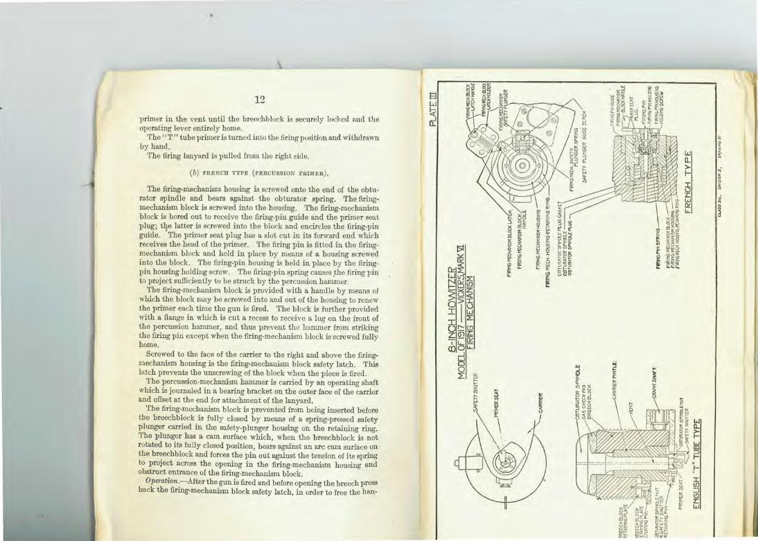
FilliNG MECHANISM.
(P late ill.)
(a) ENGLISH "T" TUBE TYPE (FRICTION PRIMER).
A. few howitzers have been designed for firing with " T " tube friction primers.
The obturator spindle on howitzers of this type extends through the outer face of the carrier. The spindle is secured by the obturator spindle nut. A spring which b ears against the nut and a shoulder inside the pintle of the carrier keeps the gas check pad tightly pressed between the mushroom head and the breechblock.
The outer end ofthe vent in the obturator spindle receives the "T" tube primer and is prepared with a bayonet joint for the reception of the head of the same. A spring is provided round the outer end of the obturator spindle for retaining the primer in position. A safety shutter iu the rear face of the breechblock prevents the insertion of a
13
primer in the vent until the breechblock is securely locked and the operating lever entirely home.
The "T" tube primer is turned into the firing position and withdrawn by hand.
The firing lanyard is pulled from the right Eide.
(b) FRENCH TYPE (PERCUSSION PRIMER) .
The firing-mechanism housing is screwed onto the end of the obturator spindle and bears against the obturator spring. The firingmechanism block is screwed into the housing. The firing-mechanism block is bored out to receive the firing-pin guide and the primer seat plug; tJte latter is screwed into the block and encircles the firing-pin guide. The primer seat plug has a slot cut in its forward end which receives the head of the primer. The firing pin is fitted in the firingmechanism block and held in place by means of a housing screwed into the block. The firing-pin housing is held in place by the firingpin housing holding screw. The firing-pin spring causes .the firing pin to project sufficiently to be struck by the percussion hammer .
The firing-mechanism block is provided with a handle by means of which the block may be screwed into and out of the housing to renew the primer each time the gun is fired. The block is further provided with a flange in which is cut a recess to receive a lug on the front of the percussion hammer, and thus prevent the hammer from striking the firing pin except when the firing-mechanism block is screwed fully home.
Screwed to the face of the carrier to the right and above the firingmechanism housing is the firing-mechanism block safety latch. This latch prevents the unscrewing of the block when the piece is fired .
The percussion-mechanism hammer is carried by an operating shaft which irl journaled in a bearing bracket on the outer face of the carrier and offset at the end for attachment of the lanyard.
The firing-mechanism block is prevented from being inserted before the breechblock is fully closed by means of a spring-pressed safety phmger carried in the safety-plunger housing on the retaining ring. The plunger has a cam surface which, when the breechblock is not rotated to its fully closed position, bears against an arc cam surface on the breech block and forces the pin out against the tension of its spring to project across the opening in the firing-mechanism housing and obstruct entrance of the firing-mechanism block.
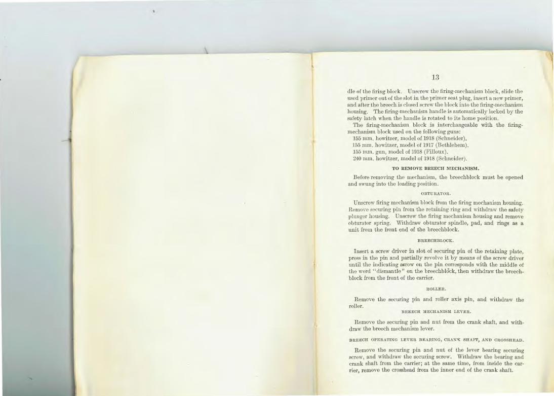
Operation.-After the gun is fired and before opening the breech press ba.ck the firing-mechanism block safety latch, in order to free the ban-
w D... > I-I 1..)
z: w [k !...
w lL
~ w ID ::::J t-= !-:r: VJ ::J \!) z: w
13
die of ilie fu·ing block. Unscrew the firing-medmn:ism block, slide the used primer out of the slot in the primer seat plug, insert n.new primer , and after the breech :is closed screw the block into the firing-mechanism housing. The fuing-mechn.nism handle :is automatically locked by the safety latch when the handle is rotated to i ts home position.
The firing-mechanism block is interchangeable with the firing-mechanism block used on the fo llowing gnns :
155 mm. howitzer, model of 1918 (Schneider). 155 mm. howitzer, model of 1917 (Bethlehem). 155 mm. gm1, model of 1918 (Filloux). 240 mm. howitzer, model of 1918 (Schneider).
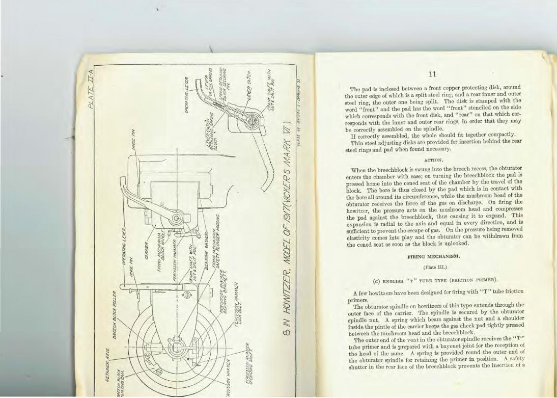
TO REMOVE BREECH MECHA.NISM.
Before removing the mechanism, the breechblock must be opened and swnng into the loading position.
OBTURATOR.
Unscrew firing mechanism block from the firing mechanism housing. RemO\·c securing pin from the ret!:t:ining ring and wiilidraw the safety plunger housing. Unscrew the firing mechanism housing and remove obturator spring. Wiilidraw obturator spindle, pad, and rings as a unit from the front end of the breechblock.
BREECHBLOCK.
Insert a screw driver in slot of securing pin of the retaining plate, press in the pin and partially reYolve it by means of the screw driver tmtil the indicating l!>l-Tow on the pin corresponds with the middle of the word ''dismantle" on the breechblock, then 11ithdraw the breechblock from the front of the carrier.
ROLLER .
Remove the seeming pin and roller axis pin, and withdraw the roller.
BREECH JIIECHAN!SM LEVER.
Remove the securing pin and nut from the crartk shaft, and withdraw the breech mechanism lever.
BREECH OPERATING LEVER BEARING, CRANl{ SHAFT, AND CROSSHEAD.
Remove the securing pin and nut of the lever beruing seeming screw, and withdraw the securing screw. Withdraw the bearing and crank shaft from the canier; at the same time, fmm inside the carrier, remove the crosshead from the inner end of the crank shaft.
14
CATCH, DREECII-OPERATING LEVER.
Drive out the securing pin of ihe spring retaining block, slide tb.e catch downward in the breech operating lever and withdraw the catch, then remove the spring and retaining block.
CARRIER.
Remove the securing pin from the carrier hinge pin, and withdraw the latter , then remo,·e the carrier and bearing "asher.
The undermentioned parts are not intended to be remoYed except on account of repali·, as securing screws or stop rivets would have to be drilled or cut to effect their removal :
Control arc. Breechblock rotating cam. Breech-operating lever catch plate. Breech block retaining p late. Safety plunger housing retainer ring.
TO ASSEMBLE THE BREECH MECHANISM.
The converse of the above 1K'l.kes place in reassembling the breech
mechanism.
CARE AND PRESERVATION OF H OWITZER AND BREECH MECHANISM.
The breech mechanism and also the projections on the exterior of the howitzer, which form guides for the latter when sliding in the cradle, should be kept clean, oiled or greased, and maintained in good working order; all working surfaces must be well lubricated, and the mechanism should be taken off frequently for this purpose.
The threads of the breech block should be free from buns; should the block not work ea.sily when the obtmator has been detached, the defect may often be remedied by careful filing, but no portion cf the thread should be cut away to remove a crack.
The breech should be kept covered up when possible, to prevent dust and grit getting into the interstices of the breech mechanism and impeding their easy working. A cover is provided for this pmpose.
List of lt~bricators in breech mechanism.
rarts to be lu bricated. Lubri- Position of lubricator. cator.
Bearing of operating lever •• _ ••. 1 0 n top side of carrier. Carrier hinge joint .• _. __ .. .. _ .. _: 1 On top side of hinge pin. Breech block and pintle of carrier _ 1 On top sido of breechbiock.
.. ~ .,
~ ~ ..
" "' ....... ~ .......
~ 0: ~
P5 ~ ~
...........
~ ~ If)
~ t5 ~ <:
~ a: C) 't: .........
a: ~ V) V)
~ ~ '->
~ ~ t..J Q_ '.I
~ Q;: < ..._
(2 \..!)
(\j
15
CARE OF THE HOWITZER.
After firing, the bore of the howitzer shou.ld be cleaned to remove the residue of smokeless powder and then oil ed. In clea.ning, wash the bore with a solution made by dissolving ' pound of sal soda in 1 gallon of boiling water. After washing with the soda solution, wipe perfectly dry, and then oil the bore with a thin coating of light slushing oil furnished for this purpose. A brush is used to apply the oil.
The breech mechanism, firing and percussion mechanisms should be dismounted from time to time and cleaned and oiled. Kerosene is issued for cleaning purposes only and may be applied with a rag or wad of cotton waste. Engine oil No. 1 is provided for oiling, and in general for lubricating all bearings not provided with compression grease cups.
The spare parts should be well coated with vaseline or heavy oil and each piece then wrapped in paper to prevent the oil from being rubbed off.
In the event of the obturator channel becoming choked with residue, the tapered portion should be cleaned with the cleaning reamer provided for this purpose, sufficiently to allow the insertion of a primer, which, when fired, wHl remove the rest of the obstruction.
AMMUNITION FOR 8-INCH HOWITZER, MODEL OF 1917 (VICKERS, MARK VI).
Separate loading ammunition is used in the 8-inch howitzer, consisting of high explosive co=on stool shell only. Each round isisfoued with the projectile filled, but unfuzed, with the fuze hole closed with a suitable plug. The weight of the projectile complete is 200 pounds. and the total weight of a complete round, including propelling charge, is approximately 211 pounds. The components of each round are the .::artridge, primer, projectile, bmsting charge, and fuze.
PRIMER.
(Plate IV.)
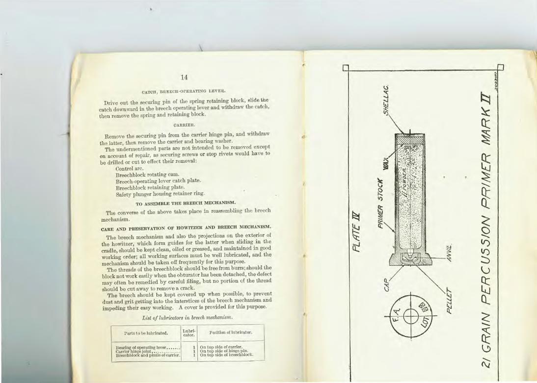
The 8-inch howitzer is made to take a percussion primer known as the 21-grain percussion primer, Mark II. This primer has no exterior thread, and is held in its seat by the firing mechanism.
To insure the ignition of the propelling charge of smokeless powder in the cartridge, it is necessary that either the primers contain in themselves, in addit~on to the percussion composition, an auxiliary charge of black powd!:r, or that an auxiliary charge of such powder be placed in the rear and core of the cartridge to communicate the flame from the percussion primer and thoroughly ignite the smokeless powder, or both.
16
The percussion primer known as the 21-graln percussion primer con· tains an igniting charge of 21 grains of black powder in addition to the essential elements of a percussion primer. The 21-grain percussion primer, Mark II, is shown assembled in Plate I V, and consists of a brass case resembling in shape a small-arms cartridge case. The head, or rear end, of the primer is countersunk, forming a cup-shaped recess, in which the percussion primer proper is fitted . The latter consists of a cap, anvil, and percussion composition, assembled as shown in Plate IV. The percussion composition contains the following ingredients:
Per cent .
Fulminate of mercmy . . . . . . . . . . . . . . . . . . . . . . . . . . . . . . 35 Chlorate of potaffi .. _. . . . . . . . . . . . . . . . . . . . . . . . . . . . . . . 35 Sulphide of antimony.... . ... .. .... . . . . . . . . . . . . . . . . 30
The percussion cap recess is connected with the interior of the primer case by a small vent. The body of the case con~1.ins 21 grains of black powder, constituting the rear igniting charge for the igniting charge in the cartridge. 'fhis black powder is inserted under sufficient pressme to retain i t in the primer, and a layer of composition wax is used to close the end. The outside smface of the wax is covered with a layer of shellac to insure water-tightness.
In action the blow of the firing pin of the breech mechanism explodes the percussion cap, which J.gnites the black powder. The flames of the latter shoot out and ignite the auxiliary charge of black powder in the cartridge, which in turn ignites the smo1--eless-powder charge.
THE CARTRIDGE.
(Plate V.)
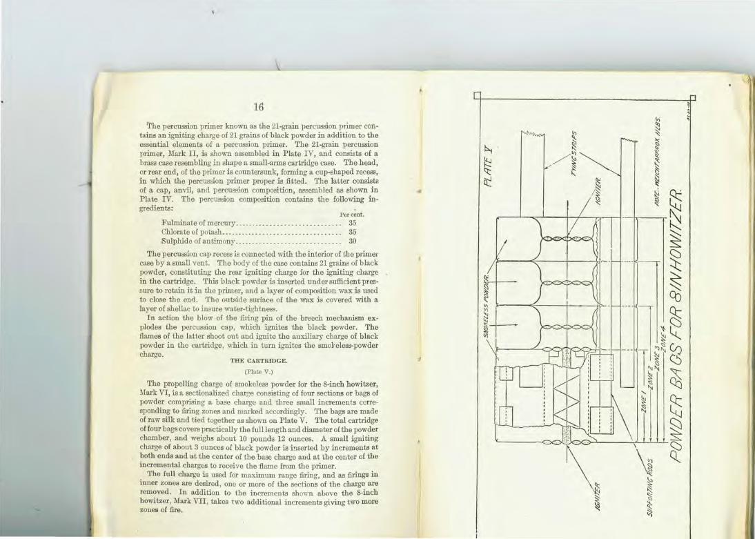
The propelling charge of smokeless powder for the 8-inch howitzer, Mark VI, is a sectionalized charge consisting of four sections or bags of powder comprising a base charge and three small increments corresponding to firing zones and marked accordingly. The bags are made of raw silk and tied together as shown on Plate V. The total cartridge of four bags covers practically the full length and diameter of the powder chamber, and weighs about 10 pounds 12 ounces. A small igniting charge of about 3 ounces of black powder is inserted by increments at both ends and at the center of the base charge and at the center of the incremental charges to receive the flame from the primer.
The full charge i s used for maximum range firing, and as firings in inner zones are desired, one or more of the sections of the charge are removed. In addition to the increments sho\\"11 above the 8-inch howitzer , Mark VII, takes two additional increments giving two more zones of fire.
.I
~ ~ 't:: a:: ~
~ ~ ~
~ ~ ~
~
(,.) ' ~ :::: ~ ~ ~ ~ !:'; ~ ~ f<j ~ ~ "' ~ S2 ~
~ ~ Qj
9:: ~[(
~ ~ ~ I Bs I ~
2t

~
~ ~ ~ ~
:li a: ~ ~ l11
~ " ~ ~ ~ ft
f5~ :s:! 8 ~ ~
·~
~ ct oq;::
~ '-! ~ ~ ~ ~ C::)
~
~ ~ co
17
THE PROPELLING CHARGE OF SMOKELESS POWDER.
The powder composing the propelling charge is a nitrocellulose powder consisting of multiperforated cylinchical grains. 'fhe weight of the charge varies slightly for different lots of powder, but is approximately 10 pounds 12 otmces. The weight is determined from the acceptance test of the lot, which also gives the standard muzzle velocity for that particular lot.
ADDITIONAL POWER INCREMENTS.
(Used in S.inch howitzer, Vickers Mark VII.)
To obtain the two additional zones of fiTe made possible by the greater chamber capacity of the 8-inch howitzer, Vickers Mark VII, sL'{ separate charges of smokeless powder are provided as against four for the 8-inch howitzer, model of 1917 , Vickers Mark VI. The base charge alone gives a muzzle velocity of 1,300 feet per second, reaching the inner zone. The maximum charge gives a muzzle velocity of 1,521 feet per second, giving the extreme range of the howitzer.
THE COMMON STEEL SHELL.
(Plate VI.)
The common steel shell for use with the 8-inch howitzer has a total length of 28.51 inches h1zed . and an ogival head struck with a radius of four calibers and is fitted with a copper rotating band forced into an undercut seat 1 inch from the base of the shell. The bottom of the band seat in the shell is roughened to prevent slipping of the band. The base of the shell is solid and is fitted with a base cover consisting of a lead disk and copper cover. which m:e calked into a circular undercut groove in the shell base. with lead calking wire. This cover is to prevent leakage of flame from the propelling charge through the shell base, which might cause a premature explosion of the shell in the bore of the howitzer . An aasembled view of the shell is shown on Plate VI.
The cavity of the shell is 24.26 inches long, 4.85 inches in diameter at its base, and 6.4 inches in diameter at about midway of the shell, and decreases in diameter toward the front in accordance with an arc radius of 3.2 calibers. Its capacity unfuzed is approximately 530 cubic inches, and fuzed , approximately 519.82 cubic inches.
When finished , the cavity is lacquered to diminish the danger of premature ignition of the bmsting charge from friction , and the exterior is painted the distinctive colors prescribed by the Ordnace Department. The loaded shell contains a bursting charge of about 29.6 pounds trinitrotoluol. The weight of the shell with bursting charge, fuze, and base cover is 200 poUllds.
18 THE FUZE.
(Plate VII.)
The 8-inch howitzer common steel shell is fitted at its front by means of a suitable adapter with a fuze known as the point detonating fuze , Mark II. The head of the fuze is shaped so as to continue the ogival shape of the shell head to a point, as shown in Plate VI.
This fuze is of the centrifugal arming type and may be fitted for either delay or nondelay action. The principal parts are as follows:
Body. Safety plunger spring. Head. Firing pin. Phmger. Firing-pin bushing. Booster tube. Firing-pin spring. Booster charge container. Detonator cap ring. Base plug. Primer (deby or nondelay). Detonator plug. Relay detonator. Safety plunger (centrifugal). Detonator spring. Safety plunger bushing.
The primer, relay detonator. and detonator proper are mounted en the plunger.
This fuze is also of the type which has what is k"''lown as the detonator safety feature . Before arming. the detonator is separated from the booster charge and is sUl'rounded by an air chamber in such a manner that if the detonator should become ignited prematurely, ei ther in storage or in the bore of the gun, the gases can expand into the safety chamber and not cause the booster charge to explode and ignite the bursting charge of the shell.
In action the detonator charge proper is located in the safety chamber, until on firing the propelling charge the centrifugal force due to tho rotation of the projectile caus(;S the safety plunger to move outward against its spring, releasing the plunger; the plunger then moves forward into the armed position and is locked there by the opening of the ring, which abuts against the shoulder on the interior of the fuze head. On impact, the firing pin is driven into the percussion prime>, which ignites the relay detonating charge; the resulting flame ignites the detonator proper, exploding the booster charge, which ignites t he bursting charge in the shell.
The centrifugal arming of this fuze is an added safety feature, it being relatively impossible to arm the fuze by ordinary handling. However, extreme care should be taken in disassembling this fuze when recovered in unexploded shell.
1=1 ~ 01. .<:(
2
~ LL.J N
~ 2 ~ <..9 a: z
~ z ~ u..J 0
I-z 0 0...
PL/lTc Ylll
8 INCH_ HOWITZER CARRIAGE MODE:L OF 1917 (VICKERS MARKlZI:)
1------ 60~/?ecoi/ -----.-.l ___ ]
19
PACKING FOR SHIPMENT.
The components of the rounds for the 8-inch howitzer are prepared separately for shipment. The common steel shell is shipped unfuzed , with the fuze hole stopped with a suitable plug. A ring bolt is fitted to the plug to facilitate handling, and a fiber or rope ring is placed around the base of the shell to protect th e copper rotating band. Punch marks on the outside of the shell indicate its size, weight, and loading.
The primers are placed in hermetically sealed tin boxes, 20 to a box, and 25 of these tin boxes are placed in a moisture-proof wooden box, which is so marked on the outside as to indicate its contents and the lot number of the same.
The point detonating fuzes are packed for shipment in a suitable wooden box, 50 in a box, which is so marked as to indicate its contents and the lot number of the same.
The charges of smokeless powder will be shipped in metal-lined air-tight containers, suitably marked on the outside to indicate the contents and lot number of the same. The number of charges for shipment will be determined by the proper authorities.
MISFIRES AND HANGFIRES.
Misfires and hangfires are of rare occurrence. In case of the failure of the gun to fire when the percussion hammer is pulled, the pull should be repeated without opening the breech. The breechblock should not be opened until after the expiration of at least one minute from the time that the percussion hammer is last pulled .
8-INCH HOWITZER CARRIAGE, MODEL OF 1917 (VICKERS MARK VI).
WEIGHTS, DII\'WNSIONS, ETC.
Weight of carriage, with howitzer ................. .. potmds .. Weight at end of trail. ............ .. ..... .. ...... . ... do ... . Weight of limber complete, with tools, approximately .. do ... . Height of axis of howitzer ... .. .... . ...... ........... inches .. Height of sight line, panoramic sight ......... . ..... .. .. do .. . . Height of eyepiece, panoramic sight ..... ..... . .... . ... do . .. . Width of carriage over axle . . . ...... . . .... ...... .. ..... do .. . . Track, carriage, and limber wheels ... ...... . ...... .. .. do ... . Turning angle . . .. . . .. ...•••.•......• ••.• •• ••.•. . .. degrees ..
19,100 588
2,600 60 69
60.5 95.8
88 40
te l.iark VIn.nd M.ark VII car.rative table oi weights, diroen-
~-}.lark VI. Mark Vll. -----lg 19,100..... .. . . 20,048-
ld 28,532 - . . . .. ... 29,532-
lS .. 60 to 21- ...... 52 to 24. lS -- oto 50--· .... . oto 45.
{4 to right.. . . . . 4 to right.
· · • · 4 to le!t....... 4 to le!t. j2tl to rig\lt... . . 2!\ to r ight.
· · · • \26 to le!t. .. ... 2!\ to le!t .
IF CARRIAGE.
: to XJV.) he howitzer may be fired at eleva-
ad1e along which it slides in recoil inder, and is returned to the firing l hydropneUJllatic recuperator. As t of recoil is decreased by means of )laced in the rear end of the recoil "bich brings the h owitzer t o rest
A> batterY· A quick-loading gear is .y be brought rapidly to the loading gen.r is so arranged that the sighting ring the operation . An emergency ilt this gear may be put out of action . cept tor rapid fire for th e reason that y locked to the elevating gear wh en giving a misdirected shot . nions to the top cn.rriage and between
IJ" , y means of a traversing gear attached the top cn.rriage. The top carriage is .nt of the t runnions to a transom on th e ~erse is 8° and is shown on an indicator l with divisions having a value of 0.1
he forwn.rd end by the axle, which i.s ·roB n.re fitted wheels Ol the tractor type.
. .,~----
(To !ace pogo 20 .)
8 .
lo/OT£:' Whee/.s ~- - .ar·e
INCH H MODOWITZE:R. - EL OF
CARR. lASE 191.7 (VICKERS MAf007I)
ratm.g haqd ,.,nee/.
Trayers'i'g hand wheeL
fitted . with ·p;· -~~'~a~q~o~n~aLI~s~/~~t~s~~~~~~~~-E·~ not shown on plate
?UJTc.IX
758S;:J
BINCH HO'vv'ITL NODE::L OF 1917
BRAKE:: GC::AR A55E:f'v
~ 1//
- 8.7>-
·~
~~ ----·---~--~
IARE/1'1/NCHt:tJ
7~2'l3"-18. (1'o f:lCO Jl"go ~ 1. )
21
The rear end of the trail is :fitted with the ordinary type of spade for firing on firm ground. This spade is bolted to the trail and may be remoYed and replaced by a float plate to which is attached a thrust bracket for use with the firing platform to be described later. For firing on stony ground or with scotches, this thrust bracket is covered by a recoil shoe which is bolted to the float plate.
The sighting gear is pivoted on a bracket attached to the cradle on the left side at the rear. The sight is kept in a vertical position by a parallel motion .
A traveling lock is provided to lock the cradle to the trail while traveling.
The principal parts of the carriage are:
Trail with spade. Traveling lock. Axle and wheel. Hydraulicrecoilcylinderwith Brake gear. variable recoil gear. Top carriage. Hydropneumatic recuperator. TraYersing gear and traversing Elevating gear.
indicator. Sighting gear. Cradle with quick-loading
gear.
TRAIL.
The trail consists of two steel flasks joined at their front ends by a tJ:ansom and at the rear by a top and bottom plate. The top plate has three oak slats fixed across it to facilitate loading. The transom is pierced vertically to receive the pivot pin of the top carriage. Each flask carries a clip in which a lug on the rear end of the top carriage slides. The top front end of each flask is fitted with a facing strip on which the saddle rests and clips are also attached at this point to engage with lugs on the top carriage to prevent the latter lifting on firing. A bracket is riYeted to either flask, underneath, in which bearings are formed for the axle. Each flask also carries brackets for the attachment of the traveling lock. Keru: the lower end of the top plate, clips are riveted for attaching the portable air compressor while charging the recuperator. The lower end of the trail is fitted with locking plates, spade, trail eye, lifting handle, and sockets for the hand spike. There are fittings on the trail for housing a combined rammer and sponge, hand spikes and loading tray, and leather cases to carry the sight clinometer and two reamers, also a block housing the oil can.
A draft link is riveted to the center of the front transom; the front end of the link is forked and is provided with a pin and key for connecting to the firing platform.
72283'-18-3
75853
SINCH HOwiTZER CARRIAGE MODEL OF 1917 (VICK[R5 MARK-siT)
BRAKE:: GC::AR A5 5C::MBLY
~ ~/
I;/
/I sccrtON A., tooKt/'IG tl'l OtRUTION or JMALL AN HOW
?U1TLX
V!CW IN OllfECTToN or LARG£ ARROW
DIMCNJ/0/VJ ARE IHINCH£Cl
L_-----------------------------------------------------------------------------------~ 722'!3"-18. ('l'o face page 21.)
22
A.."'\:LE AND WHEELS.
1e body of the axle is circular in shape and fits in bearings rside of the trail. On each end is shrunk a bracket through >olted to the trail . The brackets have cranked extensions, the axle arms. The outer end of each arm is prepared to md pin to hold the wheel in position. l'ractor wheels are supplied with this equipment. They
66 inches in diameter, with a tread 12 inches in width. Js are riveted across the tread to give a better grip on soft steel brake ring is secured to the inner ciJ·cumference of
,Is are held on the axle arms by a drag washer, cap, and a passing tl1rough the cap and axle a1·m, is held underneath
in. ls are not interchangeable from one side to the other.
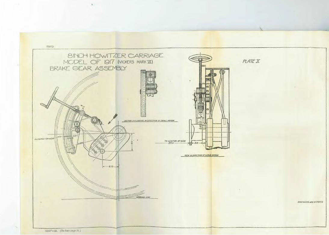
BRAKE GEAR.
(Plate X.)
Lkes for use in firing and traveling are fitted. one to each carriage, each acting independently. the axle bracket is a supporting bracket, ilie upper end of
es a rocking pin, while its lower end has p1voted to it a rming a brake hanger. The upper end of the hanger carries ;hrough which works a screw, which also pallSes through the 1e rocking pin, in which it is held by a shoulder in front rings wiili nut and pin in rear; a hand wheel is attached to .d of ilie screw. The lower end of the hanger has attached c shoe, in whicn is secured a wood block to act agaillst the m ilie wheel. Consequently when the screw is turned, the 1e upper end of the hanger, travels along the screw, revolvJr end of the hap.ger in an opposite direction and thus brillgs >bear against the wheel or revolves it clear :J.S the case may cing piJ1, revolviJ1g in its bearillg, allows the screw and nut ry movement to conform to the arc of a ciJ"Cle described by
TOP CARlUAGE.
:arri.age consists of two steel side pieces jollied at their fron ransom. mm bas a bushed opening iJ1 its center, formed ~ receive a vhich also passes tlll"ough the opening in tlle trail and is neath by ~ nu~ and pin..
722&3"-18 ('l'o lace page 22.)
8 JNCH HOWLTZERCARRIAGE:
MODE:L OF 1917 (VJCKERS MARK "21:)
ELEVATING, TRAVERSING A,IJO SIGHT OPERATING GEAR.
-........ -
PUITE.AI

SINCH HOWITZER CARRIAGE MODEL OP 1917 (vrcKER.S MARK1Zr)
QUlCI< LOADING GEAR.
- ---- :..........-. _____ _
[L(YA~'9ti LPo.)'iG W !IJGf tlbNP ?Ills Of ORtQL(
I I
PLI7TeXII
J
23
Brackets are riveted to each side piece in which are formed beMings for the cradle trunnions, hinged caps being provided to keep the latter in position. A bracket having an opening to receive the spring plunger of the quick-loading gear when the howitzer is in loading position is fitted to the front of the transom on the right side, and to the left side toward the rear is riveted a guide in which works the elevating arc. Holding-down lugs are bolted to eiLher side piece, front and rear, to engage clips on the trail which hold the top carriage down on fuing, and a bracket to support the elevating and traversing gear and sight is bolted to the rear of the left side piece. There is also a bracket on the 1ight side piece, in which is secured a stn.if to carry a dial sight.
A case is attached to the left side in which is carried the panoramic sight.
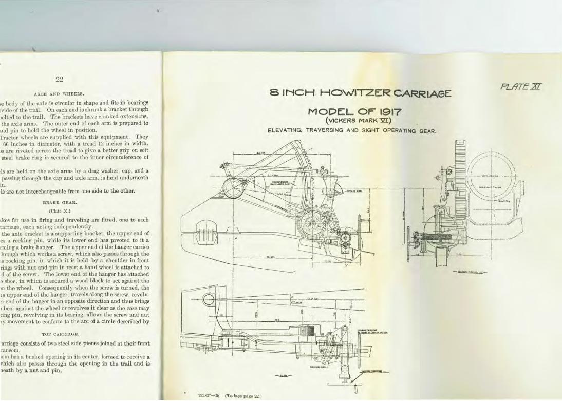
~'RAVERSING GEAR.
(Plato XL)
The traversing gear is placed between the trail and the rear end of the saddle on the left side. It consists of a pivot which is supported in a bracket on the trail. Held in the pivot is the traversing screw, the 1ight end of which works in the left end of a nut which is hinged at its right end to a bracket on the top carriage. The screw and nut are inclosed by a steel cover to keep out dirt and dust. Near the left end of the screw a shoulder is formed, and between this and the bearing in the pivot are placed ball bearings. The outer face of the pivot forms a gear casing, and keyed to the screw at thi8 point is a spm gear. Between the spm gear and the gear casing is another set of ball bearings. Gearing with the wheel is a pinion on a short spindle, supported in bearings on the trail , on which is a hand wheel for working the gears. The gear is inclosed by a cover which is bolted to the casing. The amount of traverse is indicated by a poi.J1~er on the pivot reading to grad uations in degrees on a scl!le plate attached to the top carriage.
CRADLE.
(Plate XIII.)
The cradle is U shaped and is provided with trunnions to fit the trunnion bearings in the top carriage, in which they are held by hinged caps secured by pins. The trunnions are provided with roller bearillgs to reduce the friction caused by elevati.Jlg and depressing the howitzer. Caps with flanges to fit outside the b0<1.rings on the top carriage are screwed into the trunnions and held by set screws. A top plate fitted to the cradle has top guides to take the guide 1ib on the howitzer and under guideways to take the guides on the bcdy of
24
the hydraulic recoil cylinder and recuperator. The front end is closed by a cap to which are attached the piston rods of the recoil cylinder and of the recuperator. The cap is fitted with a shutter which enables the pressure to be tested without disconnecting gears or removing the cap. Brackets are fitted to the cradle in which are formed bearings for the quick loading and the variable recoil gears. Leather pads inclosed by a brass casing are fitted to the front of the cradle to act as a stop to the howitzer in retuming to battery. The cradle projects some distance beyond the breech of the howitzer to form a suppo1t for the latter in the recoil position. This projection is prepared on the underside to receive the traveling lock and on top to receive the loading tray.
A spring pointer attached to the front guide ring of the howitzer on the left side indicates the correct amount of recoil according to the elevation at which the howitzer is fired.
QUICK- LOADING GEAR.
(Plate XII.)
This gear is provided to unlock the cradle from the elevating arc, and thus allow the howitzer to be brought rapidly to the loading angle (7° 30' elevation) after firing, and vice versa. •
The gear consists of a cross spindle supported in bearings of the underside of the cradle, to the right end of which is pinned the front end of the actuating lever, which is suppcrted in a bracket on the right side of the cradle. The actuating lever has a cranked extension at its front end, to which is pinned the rear end of a connecting rod. The latter has pinned to it at its front end a spring plunger, which, when the howitzer is in loading position, engages in a recess in a bracket on the top carriage and so holds the cradle and howitzer ready for loading. A spring buffer is fitted above this plunger to cushion the shock on the gear when coming into loading position. To the left end of the cross spindle is attached a short lever, to the upper end of which is pinned a spring plunger, which, when the howitzer is in firing position, engages in a recess in the elevating arc and so locks the cradle to the arc. There is also attached to the elevating arc an emergency clamp and stop, which, when in place, will not permit the use of quick-loading gear .
.Action.-1'he howitzer, having been fired, the actuating lever is raised. This revolves the cross _spindle and lever, withdrawing the plunger from the elevating arc, compressing the spring, and unlocking the cradle. The actuating lever then comes to the end of its slot, and continuing to lift on it depresses the howitzer to the loading position, at which point the forward plunger is forced into its recess in the bracket on the top carriage of the action of its spring.

' ' I
A Cradle. . 8 Rear closing plug. C AdjJJaf.ab/e valve Ci counter recoil buYf'er E Nut· securmg re·coilv<ilve. F Washer c/o.
8 INCH HOWITZER. CARRIAGE MODEL OF 1917(VICKERs , MARK1Zr)
RECOIL CYLINDER AND ' RE:CUPERATOR
RECOIL CY...bi~OC:R . G Recoil valve H Pt'aton . .J Piston roc/ k stu fring box . L L-Leath e r . M Gla n d .
R Ec·u PER /4. T 0 R,
. t1 lfemp Packing . o steel(.e . . P Ps c ktiHJ. spnn g. Q c ap s ecuring pack i ng. R Cradle cap . s Rec.oif cylt'nder.
• ---+---'-- ·
f'L/ITE :x:J(
S ECTIONI THRO. A.A..
72283·-ls. (To lace page 25.)
A. c,.-acJ le. B Rear closing plug. C Adjuat.able valve _ o cov11ter rPcoi/ but'rer E Nut" secur1ng f'e·coilvalve. F washer do .
A liqu1d cylmdar. B Pack ed Piston. cRam . o ThrottJe Valve.
E Th1 F Stt G l..H Gla
25
After loading, the actuating lever is pressed downward, which withdraws the forward plunger, elevates the cradle and howitzer until the rear plunger, which slides along the elevating arc, comes opposite its recess in the htter into which it engages under the action of its spring, t.hereby locking the arc and cradle together.
TRAYELIXG LOCK.
(Plate \'Ill.)
A steel channel-shaped bar has one end pivoted to the top of the right clamp of the traiL On top of the bar are two double lugs, through which it is pinned to the cradle for traveling purposes. The other end of the bar is shaped to fit into a bracket on the left flask, to which it is secured by a pin, which, when not in use, is suspended on the right side of the bar by a socket and hook.
The traversing gear must be placed at zero before connecting the bar to the cradle. When not in use the bar is housed in a bracket on the top of the right flask of the trail .
The bar is made removable in order to give clearance to the handle of the loading tray when loading.
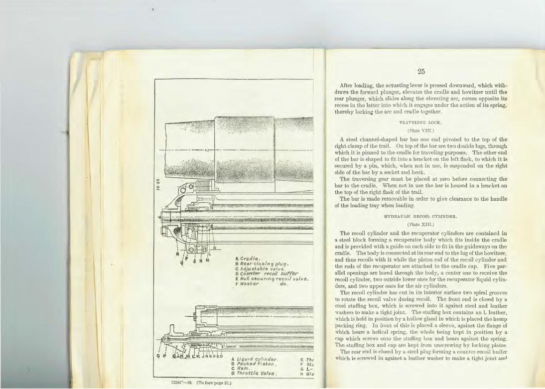
HYDRAULIC RECOIL CYLINDER.
(Plate Xill.)
The recoil cylinder and the recuperator cylinders are contained in a steel block forming a recuperator body which fits inside the cradle and is provided with a guide on each side to fit in the guideways on the cradle. The body is connected at i ts rear end to the lug of the howitzer, and thus recoils with it while the piston rod of the recoil cylinder and the rods of the recuperator are attached to the cradle cap. Five parallel openings are bored through the body, a center one to receive the recoil cylinder, two outside lower ones for the recuperator liquid cylinders, and two upper ones for the air cylinders.
The recoil cylinder has cut in its interior surface two spiral grooves to rotate the recoil valve dw-ing recoil. The front end is closed by a 8teel stuffing box, which is screwed into it against steel and leather \Yashers to make a tight joint. The stuffing box contains an L leather, which is held in position by a hollow gland in which is placed the hemp packing ring. In front of this is placed a sleeve, against the flange of which bears a helical spring, the whole being kept in position by a cap which screws onto the stu!Iing box and bears against the spring. The stu!Iing box and cap are kept from unscrewing by locking plates.
The rear end is closed by a steel plug forming a counter-recoil buffer which is screwed in against a leather washer to make a tight joint ana
:J6
The plug is threaded externally to receive a, nut, by mee.Ilil e recoil system is connected to the lug of the howitzer and t internally to form a counter-recoil buffer. A small pas!d through it, which places the buffer chamber into com-with the recoil cylinder. This passage is closed by the
cljustable valve on which is formed flats, by means of which • of counter-recoil is regulated . The piston rod and piston none forging with the count€r-recoil buffer. The rod passes the packing at the front end and is fastened with a nut to . of the trail. Behind the securing nut inside the cap the d to it a steel collar, on which is formed a bevel gear, 11·hich ; of the yariable recoil mechanism. The piston has two or the passage" of liquid from one side to the other on recoil -recoil, and a manganese-bronze ring around it to preYent e cylinder. The rod is hollow and front end is threaded :lapter, to which the pipe from the charging pump is cant filling. A small hole at the rear connects the inte,r:ior of the recoil cylinder. When the adapter is not in use the
he front is closed by a plug. The cotmter-recoil buffer the rear of the piston and has a flat cut on it for the greater
1gth. The remaining portion is cylindrical and is a close ' buffer chamber. The base of the buffer is prepared for t of the recoil Yalve and its fittings. valve is of metal and fits loosely over the base of the
1 buffer, around which it is free to 1·evolve. It bas two passage of liquid and has two studs or keys to work in the s of the recoil cylinder. The valve is held up against of the piston by a steel washer. The washer is keyed to ecoil buffer, and in turn is held by a threaded collar and
mel of the recoil cylinder is provided with filling holes, 3ed by plugs and leather washers.
VARIABLE RECOIL MECTIANISM.
(Plate XIV.)
~nism cons1sts of a steel actuating rod, held in bearings ide of the cradle; its rear end is forked and ·pinned to a :a around the right trunnion and is supported at its rear lllllion cap pin, while i ts front end is attached to a short which is formed on the outer end of a short spindle. The nside the cradle cap and carries on its inner end a bevel gages with a bevel gear keyed to the piston rod. ThUB,
72283'-18. ('l' o lace page 26.)
SINGH HO\NJTZERCARRlAGE MODE:L OF t917(VICKER5 MARK~)
VARIABL-E: RECOIL GEAR
PLilTE Xl!Z

27
when elevating the howitzer, the actuating rod pulls upon the short lever, rotating the cross spindle, bevel segments, piston rod, and piston, thereby decreasing the orifice between the ports in the piston and the recoil valve, which is held fast by i ts keys and grooves in the cylinder. This increases the resistance set up in the recoil cylinder dming recoil, thereby shortening the recoil of the howitzer. The recoil varies from 60 inches, howitzer horizontal, to 24 inches at 50° elevation, or 0.72 inch per degree of elevation.
UECtJPERATOR.
(Plate XIU.)
The recuperator is of the hyclropneumatic principle and consists of two liquid cylinders in which work rams, and two air cylinders which contain both liquid and compressed air . The air cylinders are connected at their rear ends by an equalizing passage, and are also connected to the front end of the liquid cylinders by an annular recess around the latter, along which the liquid passes on recoil and counterrecoil.
The liquid cylinders are closed at the rear end by perforated caps which are held by pins. The perforations allow any liquid which may get by the piston to get clear, otherwise the howitzer would not return fully to firing position after recoil. They also prevent a vacuum forming in the rear of the recuperator ram.
The front ends are closed by stuffing boxes, packing and caps in much the same manner as the recoil cylinder. Internally near its front end, each cylinder is reduced in diameter to form a seat for a throttle valve, which fits loosely around the piston rod and is kept to i ts seat by a helical spring, one end of which bears against the valve and the other end against the inner face of the stuffing box.
The valves are provided with a coned bead to fit tightly on their seat. Holes are bored through the head to allow liquid to pass back into the cylinders after r ecoil .
The recuperator piston rods are of steel ; their front ends are seemed by a screwed sleeve inside and a nut ou tside to the cradle cap, while their inner ends are provided with a packed piston. The packing consists of two U-shaped leathers properly h eld by supporting rings and secured by a nut, also a ring of h emp packing, which is kept tightly against the piston proper by a helical spring h eld by a nut.
The piston rods are hollow; and the front end of each is prepared to take an adapter to which the pipe fro m the charging cup is connected when filling. A small side hole a t the rear connects the interior of the rod with the liquid cylinders. When the adapter is not in use, the opening at the front is closed by a plug.

'I
28 The air cylinders ru·e plain tubes h . a th .
Pluas At the' d th ' aVJno ell' ends closed by steel o · u· rear en ey · through the body of the recu era:: connected by a passage bored the front of the liquid cylind~rs fr ' and ~e~ are also connected to valves by the rumul . om a pomt m front of the tlll'ottle
' ar passage which surrounds the li uid c li d . 1'he front closing p lugs are :fitted with air h I q y n ers. msure the correct cho,.,·ing of th 0 es at such a level as to
~o~ e recuperator · th li 'd of the left cylinder is :fitted 'th WI qm ; the front plug
t~ take an adapter, to which : co~;~~~;::~!:~n~ is a: prepared au compressor is connected when chargin"' . g .om e portable gauge is connected for tes~-g th . oo .m to which the pressure
I<UJ e all' pressm·e m the t Wh adapter is not in use the opening . 1 d b sys em . en the
A . IS c ose y a plug
is ~::~n !:c~~.cy~~= ~~:cup:ator.-For use the recoil cylinder measure) is drawn off Quan'titya out ?ned-tenth of a pint (English (54 u · · .reqllll'e about 45 En !ish ·
· S. pmts). The recuperator is :filled 'th . g pmts of 50 parts of glycerin 50 parts of t Wld a nuxture composed
U ' wa er, an 4 ounces of c ti d per . S .. gallon (5 ounces per English all ) aus c so a air hole in left air cylinder (quanti'ty g . on • up to the level of the u s · . reqllll'ed 58.5 English · ts
. . pmts), With howitzer laid horizontal and' h Is I I pm ' 70 charged with ail· to a pressure of 685 d w ee eve .' and then
B f fuin poun s per square mch e ore g, the operation of elevatin . ,., ·
correct length of recoil. g preparva the buffer for the 0~ :tiring, the howitzer recoils along the cradle . . .
recoil and recuperator cylinder th . t • tal=g With 1t the latter r·emair!in"' stationary As' the PlSilon rlino.d of the former and the
• • 0 • e reco cy der · dr b liqmd passes tlll'ough the ports m' th . il l lS awn ack, the
e reco va ve and pist h to rear .. At the co=encement of recoil th . on ·om front uncovered by the recoil valve but as ll e ports In the piston are caused to revolve on the pisto~ rod b r:o ~rocee?s the rec?il valve is causing the ports to be gradually cl~ed e ;r~~~e~ m. the cylinder, th us and absorbs the energy of recoil of th h' . mcieases the pressme
Th · e omtzer. d ~ piStons o~ the recuperator force the liquid from the li 'd .
ers m to the air cylinders the .,_., ttl al . . qm cylm-f . • w.llO e v ' ·es bema for d ff . seats or this pmpose and th li 'd . . o ce o theu
· . ' e qm entermg mto th ·. . raiSes the an· pressme in the sys• ~m R il h . e au cylinders I tl . ""' . eco avm"' ceased th I
c ose, le au· expands and forces the li uid b k o . ' e va ves the valves into the liquid cyli' d . thq ac . thiOugh the holes in fir . . . n ers us retm·nm"' th h . .
mg poSition. The hom'tze · . ' o e ow1tzer mto . . r 1s pi even ted h·om retlll' · · With Vlolence by the slowness with which th r . ~g mto battery the restricted holes in the valv d
1 b e lqmd lS forced tbr·ough
es, an a so y the counter-recoil buffer,
29
which, as the howitzer nears firing position, enters i ts chamber and displaces the liquid therein, :first over the tapering flat of the plungm·, and past tile adjustable valve tlll'ough the side channel a.Ild finally tlll'ough tile latter only.
ELEVATL';G GEAR.
(Plate XI.)
The elevating gear is supported in a bracket attached to the top carriage on the left side. Supported in bearings in this bracket is a longitudinal spindle which has at its rear end a hand wheel and at i ts front end a bevel pinion. The pinion gears into a beYel gear on the lower end of an oblique shaft, on the upper end of which is a worm which gears into a worm wheel formed on the outer end of a short cross spindle, on the inner end of which is a spur pinion which engages with the elevating arc. The latter fits loosely around the cradle trunnion on the left side and bas a recess to take the firing plunger of the quickloading geru·. When this plunger is engaged i n i ts recess, the cradle and the arc are locked together and elevation or depression ca!n be given only by working the elevating gear. The elevating arc carries on its upper side a link for attachment of one end of the connecting rod of the sight-operating gear.
The worm shaft is fitted mth friction washers at either end of the worm and an adju~ting brush mth a locking plate at its lower end. The wheels and pinions are inclosed by a metal cover seemed to the bracket with screws. A scale plate graduated up t.o 50° is attached to the bracket supporting the sight, the graduations being indicated by a pointer attached to n. bracket on the top carriage. One revolution of the bandwheel equals 45-foot eleYation or depression, as the case may be.
CARE AND PRESERVATION OF THE CARRIAGE.
RECOIL CYLINDER.
Before firing, it should be ascertained that the recoil cylinder is full, that there is no leakage at the stuffing box, that the recoil cylinder is firmly attached to the lug on the howitzer, and the piston rod to the cradle cap.
To fill the 1·ecoil cylinder .-Eievate the howitr.er to 5° (having first lashed it to the cradle to prevent it slipping back), remo,·e the nuts of the piston rods of the recoil cylinder and the recuporator, disconnect the vru·iable recoil gear, and remoYe the cradle cap.
Remove the filling plugs of the recoil cylinder and the plug at the front end of the piston rod. Screw the adapter into the piston rod,
30
attach the oil pump, aud pump iu oil until it over·tlcws at the filling holes of the cylinder, bring the howitzer to the horizontal position and see that the cylinder is full; then, by means of li. syringe, extract about one-tenth of a p~nt of otl, disconnect pump and adapter, replace plugs, cra~le cap? connect up variable recoil gear and piston rod. Quantity of mlreqmred, about 45 English pints (54 . ·s. pints).
To empty the 1·ecoil cylinder.-Lay howitzer horizontal disconnect piston rods, variable recoil gear, and cradle cap a.~ bef~re, unscrew stuffing box and run otT oil into suitable vessels.
. To tighten the packing cap.-Lay howitzer horizontal, disconnect piston rods, variable recoil gear, and cradle cap, tighten the packing cap b~ means o_f the spanner provided, replace cradle cap, connect up variable recoil gear, and replace the nuts of piston rods.
To replace packing.-Lay the howitzer horizont.'11, disconnect piston rods, etc., and remo-:e the cradle cap, unscrew cap from the stuffing box, and remoYe spnng, sleeve, and defective packing. Insert new packing and replace the parts.
To replace the L leather.-The howitzer should be firmly lashed to the cradle and elevated to a convenient height, so as to retain as much of :he oil as. possible in the cylinder. Disconnect the piston rods, vanable rec?ll gear, and cradle cap. Unscrew and remove the packing cap and spnng. Unscrew and remove the stuffing box, together with the ~efec~ive paci.::ing, care being taken to catch any oil that may run out I~ smtable vessels. Remove the old packing from the stuffing box, m_sert new, and replace the parts in their proper order. Refi ll t~e cylmder and connect up the variable recoil gear, cradle cap, and plSton rods.
RECUPERATOR,
Before_ firing, see that the recuperator is correctly charged, the nuts on the plSton rods properly tightened, and that there is no leakage at the stuffing boxes, etc.
To test th_e air presswe.-Lay the howitzer horizontal, remove the screw securing the shutter, and swing the latter clear. Remove the plug f~om the adapter hole in the left air cylinder, screw in the adapter, plugging one end with the adapter cap . Attach a pressure gauge to . the. top of the adapter, open the cut-off valve, and the gauge should reglSter 6~5 pounds per square inch. If it does not, more air must be pumped In as described under "Chru·ging." If correct, close the cut-off valve, remove the adapter, replace the closing plug and re-place shutter-securing screw. '
31
Waming.-The gree.test cru·e must be taken to see that t?e recuperator is correctly filled, as too much liquid may cause senous damage and put the howitzer out of ac~on. _Whe~ properly fille~, the recuper-ator should contain about 58.<J English pmts (70 U. S. pmts). .
On no account must liquid be added to the recuperator after filling; should sufficient liquid have been lost to reduce the pressur~ below 550 ponnds per squru·e inch, the recuperator must be empt1ed and
refilled. · d The cradle must be set absolutely horizontal, both lengthwise an
crosswise, to a. clinometer, t_o insme corr~ct filling. (See ~gs. 1 .and 2.) This is very important, for if the cradle lS elevated only! , 6 prnts too much liquid can be put in before it will overfl?w ~tholes Dan~ E, and 1° elevation will allow 12! pints too much liqmd to be put mto the recuperator before overflowing at the above holes; therefore, too mu~h cru·e can not be- taken to keep the recupera.tor perfectly level while filling. (See figs. 1 and 2. )
Take care to see that plugs are remoYed from both holes D and E. (See fig. 5.) .
If either plug is left in when filling and the cradle lB_not level crosswise, too much liquid may be put in and cause senous damage to recuperator. .
If it should be necessary at any time to remoYe from left reservou the front end plug which contains the hole and plug.~· care mus~ be taken to see tliat when the plug is replaced and the JOint made t1ght both holes ru·e practically on the vertical center line in the bottom position as shown in figure 5. . . . .
The plug in holeD in the right-hand au cylinder lS of larger diameter than plug in hole E in the left-hand air c:ylinder. However, the bottom of the hole D is level with the bottom ot the hole E.
Lash the howitzer to the cradle before removing the front cradle cap, 80 as to prevent the howitzer fTom slipping back, o~ put .a bar _t~·ough the holes in the reru· of the cradle and hold the howitzer m poSition by a. wooden block placed between the howitzer ~nd the bar. .
If the cradle cap is to be left oft for a long time, the elevating handwheel should be taken off.
In charging the recuperator with compressed air, it. is important to see that the collars are screwed onto both recuperator plSton rod_s before any pressure is put in the recuperator. The collars bear agamst the
iston rod glands and prevent the rods from being forced out to the ;ear of the cylinders when tmder pressure and disconne:ted fro~ the cradle cap. The recuperator should be filled under the lllStruction of a commissioned officer only.
I 32
Liq·uid for reczlperator.-The liquid for the recuperator ill a mh:ture composed of 50 parts of glycerin, 50 part_ of pure water, and 4 ounces of caustic soda (NaOII) per United States gallon (5 ounces per English gallon). The glycerin used in this mixture must he neutral. Blue litmus paper should not turn red on being immersed in the mixture. Hit shows red, titrate with caustic soda and stir until the acid is neutralized, w·hich will be when blue litmus paper shows no red on being immersed. The glycerin provided should test 25° Baume. If it is necessary to use a heaner glycerin, the amount of pure water should be increased.
I tis essential to keep the liquid clean and u·ee from grit when filling. Sand or grit in the liquid will cause damage to recuperator.
Figure 1 is a cross section of the recuperator, showing the correct level of the liquid, and figm·e 2 is a longitudinal section, also showing
~ ... Ph>ll,..d!na • .&l,. Rewno;., •1 ,.., tn•.
Ho!eD it~ ltH. R-1-lrPI.,r;'
the correct level of the liquid, if filled while the recuperator is perfectly level and both plugs D and E removed.
Figures 3 and 4 show how the recuperator can be overfilled and the air space consequently reduced if the recuperator is not level in either direction while it is being filled, and if plugs are not removed from both holes D and E.
Figure 5 is an end view showing the lettering of the holes and plugs for reference to these instructions, and it will be noted that on the actual recuperator all the plugs are stamped with the same letter as tl1e holes to which they belong and are in accordance 1vith this drawing.
To fill recuperator.-First let p1·esstrre out of the recuperator as follows: Elevate howitzer about 5°. RemoYe plug F and open valve G until there is no pressure in the recuperator. Close Yalve G and replace plug F.
Attach oil-pump connection and adapter at II. Set the cradle level both length1vise and cross11ise to a clinometer. It is very important that this leveling be done very carefully. The wheels of the caniage should be blocked up if necessarv.
33
. liquid until it overl'!oTt"s at D D d E and pump m o d Remove plugs an D d E elevate the howitzer about 5 , an
and E . Replace plugs an 1 ,H Brina horitzer !eYe!. remove adapter and replace J 1Jd r. uid ~til it oYerflows at D and E .
Remove plugs D and E ~t ~ andl~ simultaneously since the botto~ The liquid should overflo_w l 1 Replace plugs D and E. of the hole for each plug 18 on the same eve . ~
. -s - English pints (70 . .d uired 18 about a .a . The quantity of liqm . r~q li uid is equal parts of glycenn
U S pints). The compoSltion of thf e qt·c soda per English gallon . . "th 5 unces o caus 1 and pm-e ''ater W1 ° (4 ounces perU. S. gall~n). d . t the recuperator very rapidly,
NoTE.-If the liquid ls pumpe m -~has had time to fill up in the it may begin to overflow at D before 1 • win<> to the viscosity of the other air cylinder to the level of hole E,tsot allow the liquid to settle . . um ina for a few momen o .
17 liqmd. Stop p _P " h 'linders then resume pumpm.,. to its proper level m bot C) '
.a., l'lor
·~M·~-~ ~. ::::~2?;~:~:::~:-.::::~:R· "-Oort ... U • ••• d . -8ee that the threaded col-"tl ompresse a~r. To cha)·ge recuperator w~ 1 c . to ds Care should be taken
. perator p18 n ro · d t Iars are in posi tion on recu b . n.ly on the ooland nuts an no during pumping that these collars ear o "'
on gland sleeves of rods. 1. on the trail, and connect the
Attach the air compressor to the c Ips . . h d ]" 'Cry of the compressor.
copper plpmg to t e e 1\ h the adapter with the pressm-e gauge. Remove plug F and attac

34:
Remove the cap from the adapter, and connect the compressor pipe to the adapter and see that all joints in the pipe are properly tightened.
Open valve G and pump until pressure guage registers 695 pounds per square inch.
Close valve G and disconnect compressor pipe from adapter anrl replace cap on adapter.
R educe the pressme slowly to G85 pounds per square inch by slacking back the cap on the adapter a little and opening valve C slightly.
To make up the pressure after leakage.-Proceed exactly as for charging the recuperator with air, but, before opening valve G to admit air into the rec~perator, pump the pressure in the pipe up to G85 pounds per squaremch.
If on examination i Lis found that the pressure is between 550 and 685 pounds per square inch, it is not considered necess:l.ry that the liquid
should be interfered with, but simply pump in additional air to make the pre~ure up to 685 pounds per square inch, and only when the press~e 1s below 550 pounds per square inch should the recuperator be emptied of both air and liquid and recharged.
To empty recuperator.--set cradle about horizontal. Remove plug F and open valve G to blow off air pressure. Remove both recuperator stuffing boxes and run oil off. Remove plugs H to insme draining recuperator piston rod
35
Rock the cradle up and down on the trunnions from a few degrees elevation to a few degrees depression, to insme draining the air cylinders.
When sure there is no more oil left in the au· cylinder, depress the front end of the cradle as much as possible to run all the oil out of the recuperator passages. To do this, lift the trail eye as much as necessary.
GENERAL INSTRUCTIONS FOR CARE OF RECUPERATOR.
When putting the L leathers in the stuffing boxes of the recoil cylinder and recuperator, see that the flat surface is well-bedded down to the metal. Ii this is not done the joint may leak and cause damage to the stuffing box.
See that all leathers and all working parts and parts of the stuffing boxes are clean and free from grit before replacing them in the cylinder. The leathers should be well steeped .in oil if possible before putting in, or well oiled by hand.
Replacement of piston-rod packing.-If, dw·ing the return to battery of the howitzer, it is noticed that liquid is forced out through the holes in the closing cap at the rear end of the recuperator cylinders, it denotes faulty packing on the pistons of the recuperator and it should be remedied as follows:
The air must be exhausted, the recupertaor emptied of its liquid as previously described, and the seeming nut of the recoil cylinders and recuperator body unscrewed and removed. The operation of replacing the old pack-ing is as below:
Assembling the leather U rings, ucuperator piston.-When it is des:U·ed to replace the packing or the leather rings of the recuperator piston, the piston and piston rod should be removed from the cylinder, having first removed the stuffing box at the front end of the cylinder.
(a) To 1·eplace leather U rings.-Unscrew seeming nut and remove supporting rings and leathers. Replace with new leathers, which have previously been soaked in the recuperator liquid. Replace securing nut and pin.
(b) To replace packirg.-Remove nut on the rear end of .piston rod, take out spring and packing supporting ring. Put in new packing and replace the supporting ring, spring, and nut. Replace pin.
Care should be taken when entering the piston into the cylinder that the edges of the leather U ring are not injmed. No great force should be requ:U·ed to replace the piston in the cylinder. It should be just tight enough to require its being t.c'l.pped lightly with a mallet.
Assembling the ' packings for recuperator and recoil cylinder stt~{fing poxes.-The L rmcking hydraulic leather rings for the stuffing boxe&
36
z
~ 0:: a: ~ \0 "" 0 cr.=
~ ~ ~ :::J ::I m fd en ~ c: Ill a:
Cll U')
37 .
should be oiled all over immediately before assembling. The leather rings should pass over lheir respective piston rods with a moderate push. They should not be so loose that they will slip easily, nor should they be so tight as to require driving along the rod.
To tighten the packing caps or to replace the 1·ecuperator packing.-When it is desired to replace the recuperator packing, the ali· must first be allowed to escape before removing the threaded collar from the piston
rod. PLUG S, ETC., OF RECOIL CYLINDER AX'D RECUPERATOR.
The plugs are all provided with locking plates, and care should a 1mys be taken after any of them haYe been remoYed for any purpose to replace the locking plates.
CRADLE .
The guideways on the crad le, in which the howitzer and recoil mechanism slide, shottld be kept clean , free from burrs, and well I ubricated .
ELEYATING GEAH.
The eleYating gear should be kept clean, well lubrit:.,.u,d, and the teeth of the pinion and \Yheels greased. If there is any lost motion in the gear it should be taken up by changing the adjusting bush at the lower end of the worm shaft, haYing fil'St removed the cover.
TRAVEHSING GEAR.
'l'o be kept claan and \Yell lubricated.
BRAKE GEAH.
Must be kept clean and w-ell lubricated. Wom blocks must be replaced by new ones which are carried in the spare parts.
THAVELP-'0 LOCK.
The traveling lock must ahmys be used when traveling to prevent any strains coming upon the eleYating and traYersing gears. Before connecting it to tho cradle, it should be seen that the traversing in dicator is at zero, and that the plungers of the qtrick-loacling gear are withdraw-n from their recesses in the elevating arc and top carriage.
722S3. -18----4
38
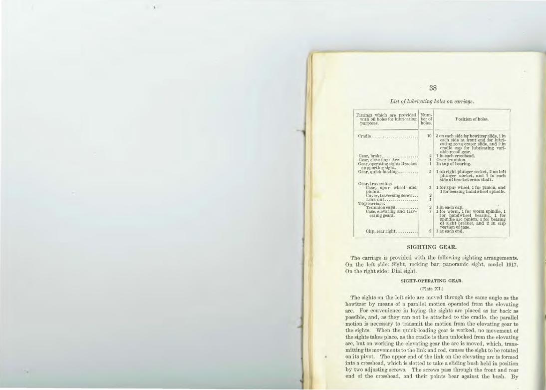
List of lub1'icating holes on carriage.
Fittings which are provided Num- I ""it.h oil holes for lubricatmg ber of Position of holes. purposes. holes.
Cradle ......•......... . ... . ... 10 3 on enrh side for howitzer slide, 1 in each side at front end for lubri-eating recuperat.or slide, and 2 in rradle cap for lubricating vari-
I able recoil gear. Gear, brake ................... 2 1 in ear h crosshead. Gear, ele,-ating: Arc .......... 1 Over trunnion. Gear, operating sight: Bracket 1 In top or bearing.
supporting sight. 1 on right plunger socket, 2 on left Gear, quick-loading ........... 5
plunger socket, and 1 in each side of bracket cross shaft .
Gear traversing: Case, spur wheel and 3 1 fo rs~u r wheel, 1 for pinion, and ginion. 1lor earing band wheel spindle.
O\Ter, traversing screw ... 2 Link nut ................. 1
Top carriaf!e: 2 1 in each cap. · Trunnion caps ......... .. .
Case, elevating and trav- 7 1lor worm, 1 for worm spindle/ 1 ersing gears. lor bandwheel hearing, 1 or
spindle arc pinion, 1 lor bearing of si~bt bracket, and 2 in clip portion of case.
Clip, rear right . ... . . ..... 2 I at each ond.
SIGHTING GEAR.
The carriage is provided with the following sighting arrangements. On the left 11ide: Sight, rocking bar; panoramic sight, model 1917. On the right side: Dial sight.
SIGHT-OPERATING GEA R.
(Plate XI.)
The sights on the left side are moved through the same angle as the howitzer by means of a parallel motion operated from the elevating arc. For convenience in laying the sights are placed as far back as possible, and, as they can not be attached to the cradle, the parallel motion is necessary to transmit the motion from the elevating gear to the sights. When the quick-loading gear is worked, no movement of the sights takes place, as the cradle is then lmlocked from the elevating arc, but on working the elevating gear the arc is moved, which, transmitting its movements to the link and rod, causes the sight to be rotated on i ts pivot. The upper end of the link on the eleYating arc is formed into a crosshead, which is slotted to take a sliding bush held in position by two adjusting screws. The screws pass through the front and rear end of the crosshead, and their points bear against the bush . By
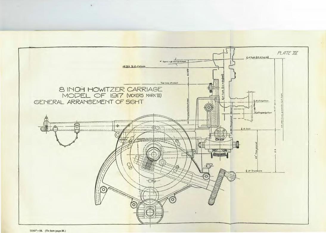
SINGH HOWITZER CARRIAG~ MODE.L OF 1917 (VICKER5 MARK"'QI)
GENL.RAL ARRANGEMENT OF SIGHT
72283"-18. (To face page 38.)
.., ..,
PL11TE .N
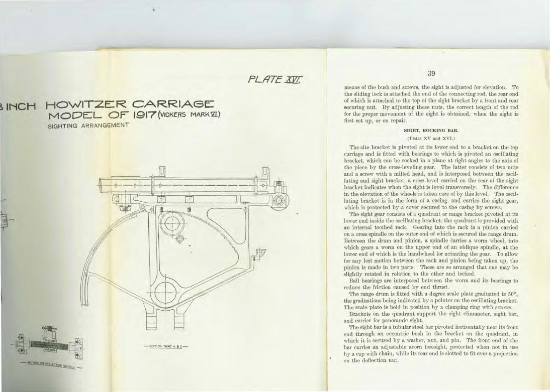
~INCH HOWITZER CARRIAGE: _rv10DEL OF J917(vrcKE.RS MARK~) SIGHTING ARRANGEMENT
-SECTION THRO' A 8 C
-~LECliOr1 .. S-p. ~-
PLI1TEXF£' 39
means of the bush and screws, the sight is adjusted for elevation. To the sliding lock is attached the end of the connecting rod, the rear end of which is attached to the top of the sight bracket by a front and rear seeming nut. By adjusting these nuts, the correct length of the rod for the proper movement of the sight is obtained, when the sight is first set up, or on repair.
SIGHT, ROCKING BAR.
(Plates XV and XVI.)
The site bracket is pivoted at its lower end to a bracket on the top carriage and is fitted with bearings to which is pivoted an oscillating bracket, which can be rocked in a plane at right angles to the axis of the piece by the cross-leveling gear. The latter consists of two nuts and a sere\\- with a milled head, and is interposed between the oscillating and sight bracket, a cross leYel carried on the rear of the sight bracket indicates when the sight is level transversely. 'fhe difference in the elevation of the wheels is taken care of by this lcYel. The oscillating bracket is in the form of a casing, and carries the sight gear, which is protected by a cover secured to the casing by screws.
The sight gear consists of a quadrant or range bracket pivoted at its lower end inside the oscillating bracket; the quadrant is provided with an internal toothed rack. Gearing into the rack is a pinion carried on a cross spindle on the outer end of which is seemed the range drum. Between the drum and pinion, a spindle carries a worm wheel, into w·hich gears a worm on the upper end of an oblique spindle, at the lower end of which is the hand wheel for actuating the gear. To allow for any lost motion between the rack and pinion being taken up, the pinion is made in two parts. These are so arranged that one may be slightly rotated in relation to the other and locked.
Ball bearings are interposed between the worm and its bearings to reduce the friction caused by end thrust.
The range drum is fitted with a degree scale plate graduated to 50°, the graduations being indicated by a pointer on the oscillating bracket. The scale plate is held in position by a clamping ring with screws.
Brackets on the quadrant support the sight clinometer, sight bar, and carrier for panoramic sight.
1.'lre sight bar is a tubular steel bar pivoted horizontally near i ts i ront end through an eccentric bush in the bracket on the quadrant, in which it is seemed by a washer, nut, and pin. Tho front end of the bar carries an adjustable acorn foresight, protected when not in use by a cap with chain, while its rear end is slotted to fit over a projection on the deflection nut.
40
In a bracket on the right side iB cut a V notch for use in conjlmction with the acorn foresight. The dellection gear iB can-ied in a crosshead formed at the rear of the quadrant, and consists of a screw with a milled head, nut in w-o parts of the sp1ing, scale plate, and graduated drum. The scale plate is attached by screws to the back of the crosshead, the graduations having a value of 10 mils, being indicated by an arrow on the nut. The drums fit over the end of the screw, and are also graduated in tenths of a mil , with indicating ruTows on the crosshead.
CLINOMETER SIGHT.
(Plate XV.)
The sight clinometer is used to give the "angle of site," and admits of 300 mils elevation or 300 mils depression . It is constructed so that i~ may be readily attached to the rocking-bar sight. 1 t consists prinCipally of a cradle with a worm spindle, and a toothed arc with a spilit level. The cradle iB fitted on the underside with spring clips for ~xing it to a bracket on the quadrant, and with radial groo,-es on top, m which the arc slides; the "1\"orm spindle passes through the center of the cradle, and is supported at each end by movable beru·ings, one of which is ph·oted to the cradle, and the other fTee to slide in grooves for a limited distance, so that the ''orm on the spindle may be readily diBengaged from the teeth in the arc when necessru·y for quick adjustment. The "1\"0rm is kept up to its work by a flat sp1ing with a bea~ing surface on its underside, and each end of the spindle is fitted with an adjustable micrometer collar marked to read in mils. The arc consiBts of a toothed segment with a spilit level above· it slides in the grooves on the cradle and the teeth engage in a wor:n on the spindle; an adjustable pointer iB fitted below the level for reading the degrees of elevation and depression engmved on the cradle.
DIAL SIGHT.
The dial sight consists of a circular carrying plate with a scale rin"" graduated in mils, a crosshead and pin, and a sight plate with pointer~ The carrying plate is hinged at the center to the crossbead, and the crosshead is hinged transversally to the crosshead pin. This arrano-ement permits an adjustment right and left to compensate for a~y difference that may occur in the level of the wheels and for elevation or depression being given to the plate and sight. 'The scale ring is fixed to the periphery of the carrying plate by screws; and is graduated in mils. ~hould it be found, by examination , that when the sight line and aXIs of the gun are parallel , zero is not indicated , the pointer is so formed as to admit of the required adjustment being made . The sight
l
41
plate is pivoted to the center of the carrying plate and joined near its center, the joint pin is provided with a thumb nut for clamping the plate in the extended or folded position; the plate is fitted with an acorn-pointed foresight at the front end , and notched to form a hind sight at the rear end. A clamping screw is provided to fix the sight plate at the required angle. The sight is fixed to the bracket by a crosshead pin. which fits into a corresponding socket on a pillar and is secured by a keep pin.
PANORAMIC SIGHT, MODEL OF 1917.
(Plate :X:Vll.)
The panoramic sight is a vertical telescope so fitted with an optical system of reflecting prisms and lenses that the gunner with his eye at the fixed rubber eyepiece (RE) can bring into the field of view an object situated at any point in a plane perpendicular to the axis of the telescope.
OPTICAL SYSTEM.
The rays coming from the object are reflected downward from the rotating head prism (RHP) into the rotating prism (RP). The rotating prism (RP) rectifies the rays; after theii· passage through the achromatic objective lens (OL) , the lower refl ecting prism (LRP) reflects them in such a way that there is presented to the eye_ lens (.EL) a reflectiJia image, which the eyepiece magrlifies. A characteristic of the rotatiii~ prism is that upon rotation about its longitudinal axis the image of the object seen through it turns with twice the angular velocity of the rotatiiig prism. The rotating head plism and rotating prism are so mounted as to rotate about this axis. the rotating prism following the rotating bead prism with one-half of the angular velocity of the latter, the image always remains as it would appear to one observing it directly with an ordina~-y telescope. The image formed by the achromatic objective lens (OL) would then be reversed and inverted. The rays a~·e cross reflected to the opposite sides of the axis by the inclined faces of the lower reflecting prism, thus correcting the reversal.
The combined action of the rotating head prism (RllP) , the rotating prism (RP) and lower reflecting prism (LRP) and the nature of action vru·ying with different positions of the prisms provide for the correction of the inversion of the image. The rotating head p1ism (RHP) and lower reflecting p1ism (LRP) as shown in position on Plate A.'VII act as parallel reflectors and they without the lens system would present an erect image. The rotating prism (RP ) , however , inverts the rays and corrects the inversion produced by the acluomatic objective lens (OL). It will be noted that the effect would be the same whether the
42
rotating prism (RP) occupies the same position shown on the plate or be revolved 180° from that position .
The rotating head prism (RHP) must be turned through 360° to get a position of 180° for the rotating prism (RP). If the rotating head prism (RHP) is rotated through 180°, the rotating prism (RP) and lower reflecting prism (LRP) would form reflectors set at right angles, and would give, without the lens system, an inverted image, and in conjunction with the lens system an erect image. The rotating prism (RP) in this case will occupy a position of 90° from that shown on the plate, in which position it causes no inversion but counteracts the inversion produced by the lower reflecting prism (LRP).
The instrument has a magnifying power of 4 and a field view of 10° .
THE PRINCIPAL PARTS.
The pr:j.ncipal parts of the panoramic sight are the rotating head mechanism, the elevating device, the azimuth mechanism, the rotating prism mechanism, the counting device, the shank, and the elbow.
ROTATING HEAD MECHANISM.
The rotating head mechanism consists principally of the rotating head (RH), rotating head prism (RHP), rotating head prism holder (Y), prism holder coYer (r2), elevation index support (G2), prism shield (Sl), and rotating head cover (01).
The rotating head (RH ) forms a housing for its movable parts, and provides seats for the elevation-worm ball socket and cap (2B and lB), and rotating head prism holder (Y). The front opening of the rotating head is closed by the prism shield (Sl ), which forms a dust guard. The bottom threaded seat of the rotating head screws upon the upper end of the azimuth circle (J), and is locked in place by four rotating head retaining screws (B.). Upon the rear face of the rotating head (RH) is engraved a scale (G3), which is used for measuring the elevation of the rotating head prism holder (Y), which retains the rotating head prism (RHP), and has an index mark upon the projection coinciding with the graduations of the elevation micrometer (Rl), thus measuring the angle of site.
The rotating head prism (RHP) is mounted within the rotating head prism holder (Y) between the prism support front (S), prism support bottom (T), and prism support back (X), and is secured in position by the rotating head prism spring (Xl), whicli bears upon· the prism support back (X). The rotating head prism (RHP) is protected on the right side by the prism holder cover (02) and on the left side by the elevation index support (G2). The movement of the rotating
'6
~
:1] .
p
?f.I1Te XW1
NOTE .SCREWS MARKED @MAY Bt ADJUSTE:D IN SERVICE. ALL OTHE:R ADJUSTME:NTS TO BE MADE BY THE: ORDNANCE DE:PARTMENT ONlY
MODEL Or 1917
CLASS ~6 DIVISION IS. DRAWING 23 72:

72283"-1 . ('l' o faco pago ~::?. )
?iJlTe XWI
NOTE .SCREWS MARKED @MAY Bt ADJUSTED IN SERVICE. ALL OTHE:R ADJUSTMENTS TO BE MADE BY THE ORDNANCE DEPARTMENT ONLY
PANORAMIC SIGHT, MODEL Or 1917
CLASS 36 DIVISION IS, DRAWING 23
ro· be
ge hE ar ar ar p! or tl:
rr t2 el
h c sJ
p 1
g t r 1:
43
head prism holder (Y), upon which the elevation segment (WS) is cut, is accomplished by the elevation worm (El ), and the length of travel is controlled by seven brass stop rings (R2). Each ring has a small tongue, the edge of which engages at each revolution of the elevation worm (E1) with the tongue on the adjacent ring. Each Ting is thus engaged in its turn until si .. 'C revolutions have been made, when the tongues are all in contact. and no further movement can be made in that direction.
The prism shield (S1) is held within the rotating head (RH) by the prism shield retaining piece (3A), which is in turn secured by two prism shield retaining piece screws (2A).
The prism holder cover (02) scTews into its threaded seat located in the right side of the rotating head prism holder (Y) and is locked in position by the prism holder cover screw (03).
The rotating head cover (Cl) screws into its threaded seat located in the right side of the rotating head (RH) and is held in place by the rotating head cover screw (S7). The exterior of the rotating head cover (Cl) has two small holes for teat >aench, and engravings "Field 10° " and "Power 4" are located on the exterior surface.
The elevation index support (G2) screws into its threaded seat located in the left side of the rotating head prism holder (Y), and is secured in place by the elevation index support screw (G7). The small holes in the exterior surface allow the use of a teat wrench, to enable the elevation index support (G2) to be screwed in place. The support retaining ring (G4) retains the elevation index support with rotating head prism holder within the rotating head and is locked in position by the supporting ring screw (G5).
The elevation index (G6) is held upon the elevation index support (G2) by the two elevation index retaining screws (GS). The arrow engraved upon the German-silver piece which is dovetailed in the elevation index (G6) coincides with the graduations of the scale (G3) engraved upon the real' face of the rotating head (RH).
ELEVATION DEVICE.
The elevation device consists principally of the elevation segment (WS), elevation worm (El), elevation worm ball cap and socket (1B and 2B), elevation worm plunger spring and plug (S3 and B2), elevation micrometer (R1), seven stop rings (R2), and elevation index (G6).
The elevation segment (WS) is hob bed into the rotating head prism holder (Y) and meshes with the elevation worm (E1).
The elevation worm (E1) is mounted in the back of the rotating head (RH) in a ball and socket bearing (2B ), which in conjunction with
44
the elevation worm plunger spring (S3) and plunger (E2) prevents back lash between the elevation worm (El ) and the eleYation segment (WS).
The elevation micrometer (R1) is held upon the upper slotted end of the elevation worm (E1) by the micrometer locking screw short (82). The scale engraved upon the periphery is graduated into 100 equal divisions, numbered eYery 10 cliY:isions. The upper exterior diameter of the elevation worm micrometer head is straight knmled to facilitate tuming. One complete revolution of the eleYation micrometer (R1) is equal to the distance between each graduation upon the scale (G3) on the rear face of the rotating head. Each graduation represents 100 mils, and the scale (G3) is so planned that the line of sight is horizontal when it reads 3.
OPEX SIGHT.
The open sight (OS) is constructed of bronze plate bent to , hape, having an arm projecting out at each end, each arm containing a hole. A bronze knee is soldered to the interior of-the front projecting arm over the center of the hole in such a manner a8 to form a sight which is used for quick sighting. The open sight (OS) is seemed to the rotating head cover by two open-sight retaining screws.
AZThl.UTU 1!ECIIANISXI.
The principal pru:ts of the azimuth mechaniom are the azimuth circle support (I), azimuth circle (J), azimuth worm (M), bearing socket (WB1), and bearing cap (\\B), throw-out plunger (P6), and spring (N), spring plate for azimuth circle (K), azimuth circle hood (AH), azimuth micrometer (P1), azimuth index (A4), arrcl micrometer index (P2).
The azimuth circle support (I) screws on the shank (G), to which it is pinned by two dowels (D). The rotating prism held by a screw in its holder is screwed into the supporting sleeve (P3) and then placed in the shank (G). The azimuth circle (J) rests on the tapering wall of the azimuth circle support (I) being held in place by the spring plate for azimuth circle (K) which along with the azimuth circle hood (AH) covers the rotating pa1-ts of the azimuth mechanism. The spring plate (K) fumishes the necessru·y friction between the azimuth circle (J) and the azimuth circle hood (AK). In the left side of the azimuth circle hood (AH) the azimuth worm (M) is held in a ball and socket bearing (WB) so that by means of a throw-out crun (0) the worm (:II) may 1e thr·own out of mesh with the azimuth circle (J) for quick approximate adjustment in sighting, but is 11ormally held in mesh by the thr·ow-out phmger (P6) and spring (N).
,
45
The German-silver strip on ·the bottom of the azimuth circle is divided into 64 equal cliYisions and each eYen number is numbered. As each complete turn of the azimuth worm (~I) rotates the azimuth circle (J) one di'ision, and the azimuth micrometer is graduated in 100 divisions, each di'ision on the azimuth micrometer (P1) represents 1/6400 of the circumference or 1 mil. Therefore an angular movement of one division on the azimuth micrometer causes a lateral displacement of so near 1/1000 of the range that the clifierence is disregarded. Thus the numbers read through the azimuth circle window (A W) represent hundreds of mils, and the reading on the azimuth micrometer (P1) represent mils. On the azimuth micrometer starting from 0 in each direction, every tenth di.,·ision i R numbered in reel or black, those in red gh·ing left deflection and those in black right d~flection. The micrometer index (P2) has two arrows, one marked "L" and the other " R, " engraved on it; the " R" fi lled in in black and the "L" in reel. The azimuth index arrow is filled in with black . As the micrometer index (P2) is fastened tightly to the azimuth worm (~I) it must turn with it, but the azimuth micrometer (P1) does not as the locking spring (LS) and deflection locking plate (LP ) preYent it from turning when the azimuth worm (~I) is turned. As the azimuth micrometer (Pl) may be turned independently of the worm (l\1) it can be so set as to be used for a cotmting cle,ice.
The shank (G) forms a body for the instrument and proYides a seat for the azimuth circle support (I ) to be doweled to and a thread at the lower end for the elbow (E5) to screw into. On the front of the shank (G) is aT lug (II) that fits into aT slot at the top of the rear sight in which it is held by a screw with knurled head.
ROTATING PRISM MECHAKISM.
The rotating prism mechanism consists principally of the rotating prism (RP), rotating prism holder (PC), supporting sleeve for rotating prism (P3), and the pinions for rotating priFm and rotating head (P4) . The azimuth circle (J) i s geared by means of two pinions (P4) turning on the pinion shaft (P5) Eet in the azimuth circle support (I ), to the rotating prism holder (P ) so that the angula.r moYement of the rotating head (RII) is twice that of the rotating prism holder (PO) . The rotating pri~m (RP) i s retained in the rotating prism holder (PO) by a set screw (RS) and a block (B3) cemented to the rotating prism (RP) after the prLm is ground out to fit it.

46
EI,BOW.
The principal parts mounted in the lower end of the elbow are the reticule (F), reticule cell (RC2), achromatic field lens (FL), achromatic eye lens (EL), eyelens cell (EC), and rubber eyepiece (RE).
The achromatic objective lens (OL) is mounted in the upper end of the objective lens cell (LC). This cell is secured in its threaded seat in the upper end of the elbow (E5) by two objective lens-cell retaining screws (CS).
The elbow is screwed in the lower end of the shank (G) and seemed by the four elbow retaining screws ( 4ES) in such a manner that its projecting arm is perpendicular to the axis of the instrument.
The lower reflecting prism (LRP) remains stationary as it is fu·mly pressed against seats machined in the elbow (E5) by a holder (X2) fitted to a seat at the bottom of the elbow. The tension of this holder is regulated by a wedge (W) to the required amount. Upon the right side of the elbow (E5) is an opening through which the light is thrown upon the reticule (F). 'l'his opening is covered by "the window (SW) to protect the interior of the eyepiece from dust and dirt. The shutter (84) is so designed to slide oYer the opening in the elbow (SW), being guided by the shutter stop screw and movement limited by the elongated slot.
The reticule (F) has two cross lines etched on its surface and is mounted in the forwarded end of the reticule cell (RC2), which is secured in the eyelens cell (EC) by t he reticule cell retaining screw. The horizontal cross line of the reticule is graduated in mils.
The achromatic eyelens (EL) is mounted in the eyelens cell (EC) and is separated from the achromatic field lens (FL) by the lens separator (LC3). The achromatic field lens (FL) is held within the eyelens cell (EC) by the field lens retaining ring (LS3), which in turn is locked by the field lens cell retaining ring screw. The eyelens cell is secured to the elbow by the eyelens-cell retaining screw (ESl) .
All interior metallic smfaces exposed to the refracted light arb finished with dull-black baking enamel. All exposed optical elemen~, covers, and nonrotating joints are sealed with the litharge cement or equal. All German-silver graduated surfaces are sandblasted and lacquered .
NoTE.-Screws marked (AS) may be adjusted in service. All other adjustments to be made by the Ordnance Department only.
47
Nomenclature of parts of panoramic sight, model of 1917.
Symbol.
1 All .... . ....... . 2 AW ...... . .... . 3 lA ...... .. .... . • 4 2A . . ..•.....•••• 5 3A .. ... ... ...••• 6 A4 ..... . .•••••.. 7 lB ...........•. . 8 2B ............. . 9 B3 .. . ... .. ..... .
!0 cs ....... . ..... . II Cl. ............ . 12 C2 .........•... . 13 C3 ...... . ... .. . . 14 D ...... .• . . .... !5 EC .... ... .. . .. . !6 EL . .•. .. •.. .. .. 17 ESL. . . .. ...... . 18 El. ..... . . . .... . !9 E2 . ... . .. ..... . . 20 4ES ..... ... ... . 21 E5 ... ... . .•. ... 22 F ...•..... ... ... 23 FL . . •.. . ....... 24 G ..• •• . •.. .. .... 25 02 . •...•. . . . •... 26 03 . ....•. .. ..... 27 04 ........ .. ... . 28 05 . .. ... .... ... . 29 06 ...... . ...... . 30 07 ............. . 31 08 ............. . 32 H ..•. . •... . •... 33 5ITS ......••. .. . 34 I. .... . · · ······· 35 J .. .. . . . ... . ... . 36 K •. . . ....... .. . 37 L .....•.• ...• ... 38 LC .. .... •. ... .. 39 LP . ... . ..• . ....
:~ t~.~::::::::::: 42 LC3 . . ..... .. .•. 43 LR3 . ...•... . ..•
:tl ~:::::::::::::: 46 0 ..•• . .•... .. •.. 47 OL .•.... . .. .• ..
:g ~~:: : : : :::::::: 50 PC ....• .. .•...• 51 PS ...• .. . ...•. . 52 Pt.. .•.......... 53 P2 .. .. . . .... .. . . 54 P3 .. ... . .... .. . .
gg ~L::::::::::: 57 P6 ..• . ........ . . 58 RC2 .. .• .....•.. 59 RE ... . ...•. .• . . ~~ ~~i;···· ······ 6?. RN •. :::::::::::
Name or part.
A<imuth circle hood. Azimuth circ le window. Rotating bead retaining screw. P rism shield retaining p iece screw. P rism sWeld retaining piece. Azimuth index. E levation worm ball cap. Elevation worm ball socket. Block in rotating prism. Objective lens cell retaining screw. Rotating head cover. Prism bolder cover. Prism bolder cover screw. Dowel pin. Eye lens cell. Achromatic eye lens.
~fe~~t~~;~~~~~ining screw. Worm p lunger spring plug. Elbow retaining screw. Elbow. Reticule. Achromatic field lens. Shank. Elevation index support. Scale. Support retaining ring. Support retaining ring screw. E lavation index. E levation index supl?ort screw. !f~~~eo~ index retamlng screws.
Azimut'f; circle hood screw. Azimuth circle support. Azimuth circle. Spring plate for azimuth circle. German silver strip. 0 bject lens cell. DeOection locking plate. Lower re!lecttug prism. Locking sprtug. Lens separator. Field lens cell retaining ring. Azimuth worm.
~rr~· out cam. Achromatic objective lens. Open sight. Throw out lever. Rotating prism bolder. Pinion shaft. -Azimuth micrometer. Micrometer index. Supporting s leeve Cor rotating prism. Piruons Cor rotating prism and rotating bead. Azimuth worm knob.
~~fc~I~~~B~unger. Rubber eyepiece. Rotating bead. Rotating head prism. Spring retaining nut.
model of 1917-Continued.
rre or part.
screw.
~w, short.
1w, long. rew.
tring. holder. rider.
; SIGHTS.
ust be made by a mechanic lp who is designated for this
ritzer horizontal by means et the sight gear on stops. f not, adjust as follows: :ing the retaining plate,
3:0ULD BE IN '!'HE CENTER
I LEVEL TRANSVERSELY.
the panoramic sight socket ) and bring the bubble of ng the cross leveling gear. Je in the center of its run . nechanic fTOm the 1\Iobile
SHOULD DE IN 1.'HE CENTER
)\VITZER LAID ITORIZONTAL
f the clinometer plane of r of its run by working th e
PLfiT£Xt?il
TARGET FOR TESTING ·SIGHT OF 81NCH HOWrTZER.,MODEL OF 1917 (vrcKERs MARK~ NOTE:- When testing set the Sight at Zero Elevation and 1° Le-ft Deflection I the l,.atter being indicated by
a Red Mark
SCAL.E=~.
No-te:On carriages built in the U.S., Model of 1917, the line of .sights is par~llel
I with bore of gun . There is r-10 · 1° leff ~eflect-'1on.
~-· ·-·-----·-·129_ :..§__ __________ ~ ·- . -------{
! i i - ----·--· ---+--2?·09 _________________ j
I~ , ·o I
T ~~ 25·67 1~-~~-~~-- -------------.-- -~------ -------------- - -------------- - ---- -
'12283"-18. (To face page 48.)
B. Bore of Howitzer
T. Telescope •
(Br-i+•sh)
S. Open Sight.
D., Pa.rtora..mic: S i thf" (Bri+•at-. and ~· S.)
B

49
elevating gear of the carriage. Set site clinometer and range drum at zero. The bubble of the Rite clinometer should now be in the center of i ts run ; if it is not, adjust as follows:
Adjustment.-Bring the bubble of the site clinometer to the center of its run by working the milled head. Slacken the screw seeming the indicator of the mil scale and the nut securing the micrometer scales shift indicator and micrometer scales to zero and reclamp.
4 . To VERIFY PARALLELISU OF Lh'I"ES OF SIGHT A..'\'D AXIS OF BORE.
The sights are correctly adjusted when, at zero elevation and deflection, the lines of sight are parallel to the axis of the bore.
When the carriage is placed with wheels on a level platform, the howitzer with axis of bore horizontal, and the sights at zero elevation and deflection, the points in which the lines of sight and the axis of the bore prolonged pierce a distant plane perpendicular to the latter should be located with refereuce to each other as indicated on Plate XVIII.
A target made according to the dimensions on Plate XVIII should be placed in a vertical position perpendicular to the line of sight at a distance of not less than 100 yards from the howitzer, and at such a height that the point B is at the same height as the axis of the bore of the howitzer. The verticality of the target should be assured by a plumb line attached at X and coinciding with the vertical line through B .
The carriage should be rested on carefully leveled solid supports ; the howitzer should then be directed so that the axis of the bore, prolonged, pierces the target at the proper point. The lines of sight of the open and panoramic sights, if adjustment is true, should pierce the target in the points marked Sand D, respectively.
In order to train the bore of the howitzer accw·ately on B, secure two threads or hairs at the muzzle, fastening them perpendicular to each other with the point of intersect-ion coincident with the axis of the bore and sight through the axial vent of the breech mechanism.
In the field, where from lack of time or proper facilities the method just given can not be followed, the adjustment of the sights may be verified by bringing the lines of sight at zero elevation and dellection to bear upon some sharply defined point of a distant object. At such a range (for instance, 2,000 yards or more) the parallax may be neglected, and if the sights are correctly adjusted the lines of sight and the prolongation of the axis of the bore will sensibly pass through the selected aiming point.

50
ustment of the sights is of such importance and should be J frequently that battery commanders will find it advan' make permanent arrangements for such verification. The mpports constituting the carriage emplacement should r be of stone. The site of the target (Plate XVIII) should :ed, and the exact locations of the target and horizontal points permanently marked. If these arrangements are
nade, subsequent verifications of sights will become a simple
ADDITIONAL TESTS.
te sights are adjusted they should be subjected to the followo insure their accuracy at extremes of elevation and azimuth: h carriage level and howitzer and sights at zero elevation and the lines of sight and axis of bore prolonged pierce the target
oper points. o howitzer is then moved to its maximum elevation; as the ·ation is altered the lines of sight should follow the vertical ugh the same points of the target. h conditions as in (a) the howitzer is moved upon the carriage reme positions in azimuth; as the sight deflections are now te lines of sight should follow the horizontal lines through points on the target. struction and assemblage the sights, if correctly adj usted, 11fill the above conditions with substantial accuracy. If oted, a report of the facts of the case with the cause, if known, ' made to the ordnance officer charged with the repair of the 'or his information and action.
81NCH HOWITZER CARRIAGE
1 Vicpedeof· 2 Vicyl 3 Vicliner 4 Viciaton 5 Vich~tft 6J Vic!'Dtric
72283"-18.
7 8 9
10 11 12
MODEL OF 1917 (VICKERS MAR~) AIR COMPRESSOR.
<"REAVELL VERTICAL TWO STAGE).
CODE WORDS. Vicheave 13 Vichipack Vicweel 14 Vichijunk
19 Vicdelcnp 25 View asher 31 Vicstaffer Vi cover IS Vicscap
20 Vicdelplug 26 Viclubr 32 Viclokein Vicgugpin 16 Vies plug
21 Vicdelseat 27 Viclupipe 33 Vicgib ey Vicpl•le 17 Vicsea.t
22 Vicdeval 28 Vicacrew 34 Viclubrak Vicloq,aek 18 Vicoalve
23- Vicdepring 29 Vi cooler 35 Vicwatlet 24 36
(To face pago 50.) Vicaupring 30 Vicfiller Vicbipau
PLflT£ XII
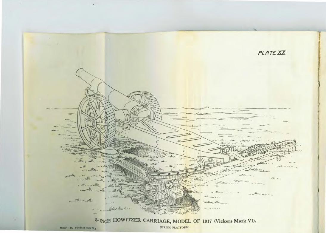
PLI1T£XZ
f -·-----===---""~"'-~ -----
----·- .:-:.----
...;._,t!l(......___. -~~ ~~-""-----'·-z...
,...,_,.,. \ L.\.tt\o•c...-.:..,,.-._
•.•• ~~~ ...... ,,d/t.,
._, ,~ ......... .
8-INci-1 HOWITZER CARRIAGE, MODEL OF 1917 (Vickers Mark VI). 73283"-:18. (To fa® pageiJ.) FIRING PLATFORM.
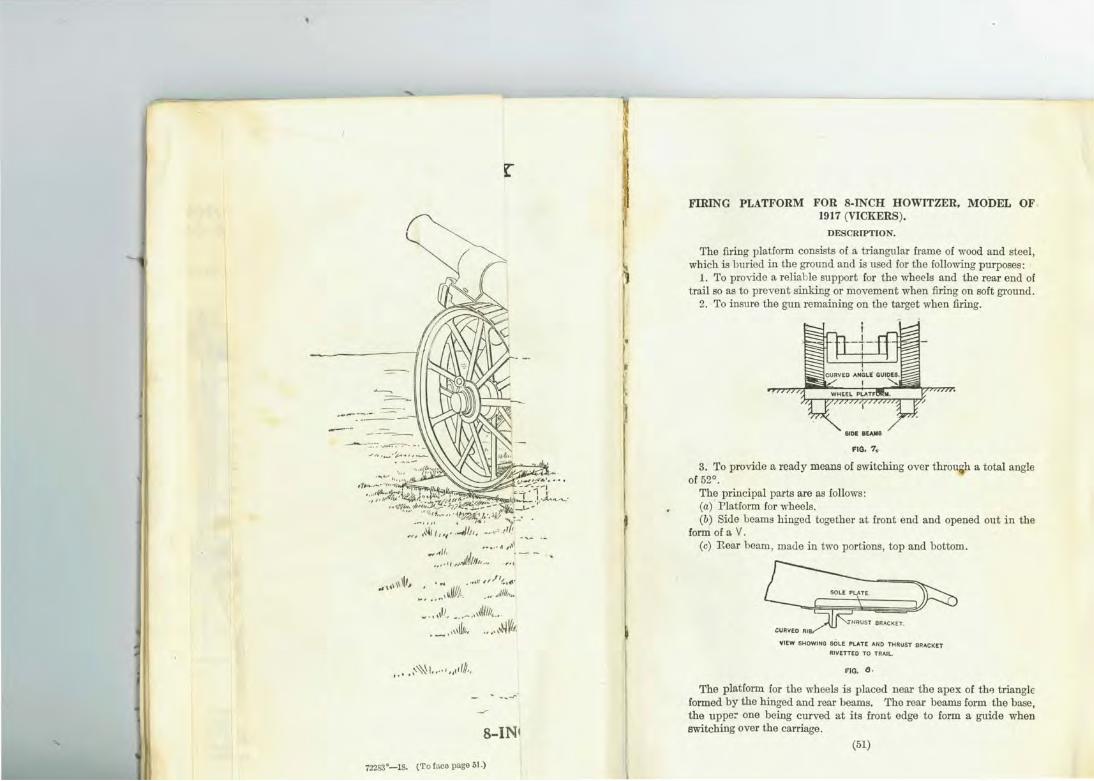
r
1/ , ..... .. ... ~·'' _ .. ' , }
.. ... , ... .JJ.~/1/t ....
,.,,./ ~, ~'''·"'· • . ·:~11/1;.. . ... ,J/16 ...
... , ••''
~ .. ,,It •.. - ..• ,~1/!J, .• . - . ,,,\~.. . ...... ~w,.
__ _,.
8-INt
72283"-18. (To !:leo page 51.)
FIRING PLATFORM FOR 8-INCH HOWITZER, MODEL OF 1917 (VICKERS).
DESCRIPTION.
The firing platform consists of a triangular frame of wood and steel, which is buried in the ground and is used for the following purposes:
1. To provide a reliable support for the wheels and the rear end of trail so as to prevent sinking or movement when firing on soft ground.
2. To insme the gun remaining on the target when firing.
3. To provide a ready means of switching over throu h a total angle of 53°.
The principal parts are as follows: (a) Platform for wheels. (b) Side beams hinged together at front end and opened out in the
form of a V. (c) Rear beam , made in two portions, top and bottom .
YIEW S~OWING S6LE PLATE AND THRUST BRACKET
RIVETTEO TO TRAIL.
I'IG. tJ .
The platform for the wheels is placed near the apex of th'3 triangle formed by the hinged and rear beams. The rear beams form the base, the uppe: one being curved at its front edge to form a guide when switching over the carriage.
(51)

52
The carriage wheels rest on steel plates on the wheel platform, and are guided by curved steel angles which prevent lateral moYement of the gtm off the target.
TRAIL Et40, WITH THRUST BftACKI!T
RIY£TTED ON. FIG. 8 ·
The wheel platform and rear beams are registered in position on the side beams by means of angle brackets. The rear beams are seemed together by ~amps at the ends and middle, and in addition a screw secures the upper rear beam to each side beam.
SECTION THROl.GH REAR BEAMS ON CENTRE LINE OF TRAIL.
fiG. 10
The trail is fitted wiili a sole plate and a thrusL bracket bolted to the underside of the trail, instead of a spade. (See figs. 8 and 9.)
The thrust bracket is proYided wiLh a curved rib projecting downward into a slot in the rear beam, which takes the thrust of the recoil and also guides the trail end when switching from one position to another. (See fig. 10.)
r'Lr?TEXXI
,
-I
,,_ ~"~ f(l// ~ I
IODEL OF 1917 (Vicke RANGEMENT. r

52
eels rest on steel plates on the wheel platform, and ved steel angles which prevent lateral movement of
set.
TRAIL END, WITH THRUST BRACt<tT
RIVeTT£.0 ON.
FIG. 9 ·
tform and rear beams are registered in position on the neans of angle bracket.s. The rear beams are secured :1ps at the ends and middle, and in addition a screw
:r rear beam to each side beam.
SECTION TI-IROI..oGH REAR BEAMS ON CENTRE LINE OF TRAIL.
FIG. '0
itted wiLh a sole plate and a thrust bracket bolted to the te trail , instead of a spade. (See figs . 8 and 9.) >racket is provided wiLh a cmved rib projecting downt in tbe rc:J.r beam, which takes tbe thrust of the recoil as the trail end when switching from one position to
I fig. 10.)
- ·---- ---- -~ -------~~------
t l. / · ,__,..
8-INCH HOWITZER CARRIAGE, M 72283•-ls. (To fnce pnge 52. )
TRAVELING AJt~

PLriTeXXl
----~ --
I
/ //;?< . ' ' ·--,. , ~
- -....- ·-.
·INCH HOWITZER CARRIAGE, MODEL O,F 1917 <Vickers Mark VI). TRAVELING .\J~Jt.'NGEMENT•
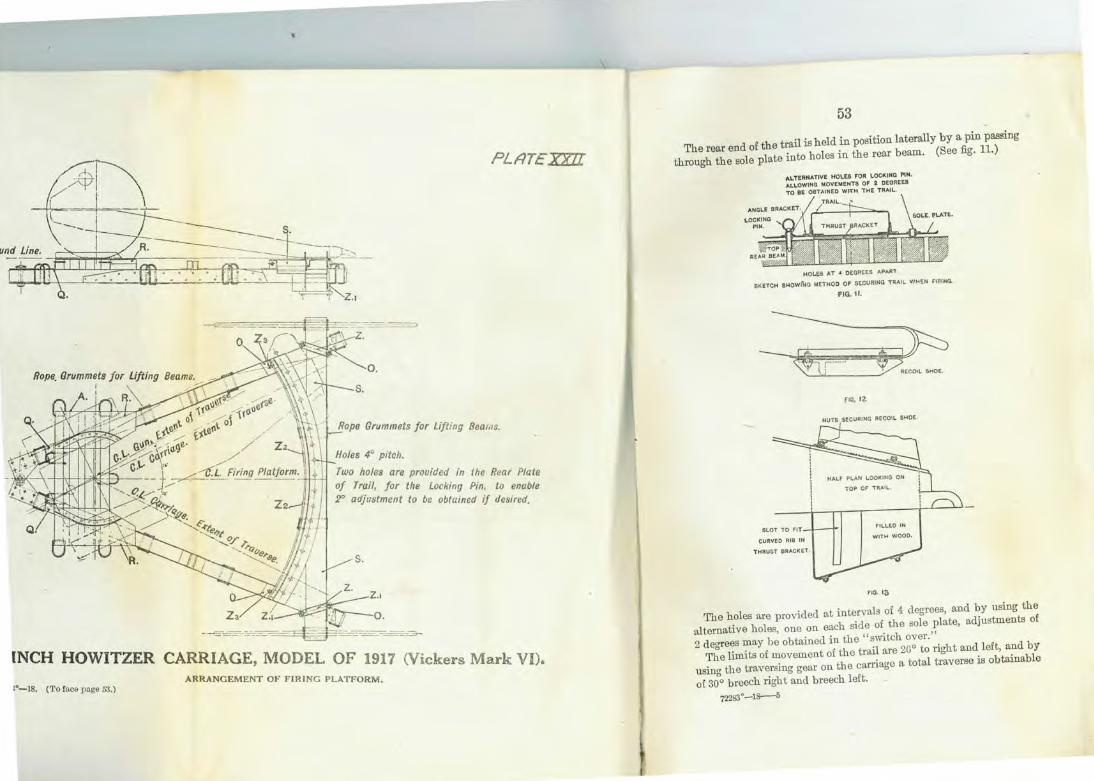
PLtc!TEXXJI
Two holes are prouided in the Rear Plate of Trail, for the Locking Pin. to enable 2" adjustment to be obtained if desired.
0.
INCH HOWITZER CARRIAGE, MODEL OF 1917 (Vickers Mark VI). A RRANGEMENT OF FIRlNG PLATFORM.
1•-18. (To face page 53.)
53
trail is h eld in position laterally by a pin passing The rear end of the . h 1 . th e rear beam. (See fig. 11.)
through the sole plate Into 0 es m
ALTERNATIVE HOL.E8 FO't I..OCKING PtN . ALLOWING MOVENEHT8 OF 2 DEGREES TO BE OBTAINED W~H THE TRAil.
HOI..£$ AT .. DEGREES APAA"T
GK ETCH 8HOWlllG METH OD OF SECURING T~A!I. WHEN FIRING.
FIG. II. --fiG. 12.
tiUTS SECURING RECOI L SHOE
no. 13
. · . ·al f 4 derrrees and by using the The holes are proVlded at mt~n 8
I 0tb l l~te adjustments of
alternative holes, one on e:J.ch side o. e so ~ '~ ' · d · th "sWitch ove1
2 degre~s ~ay he obtame 1: th etrail are 2Go t~ riaht and left, and b y The lillllts of movement o e . 1 tr" rse is obtainable
usina the traversing gear on the carnage a tota ave of so"o breech right and breech left.
msa·- 1s--s
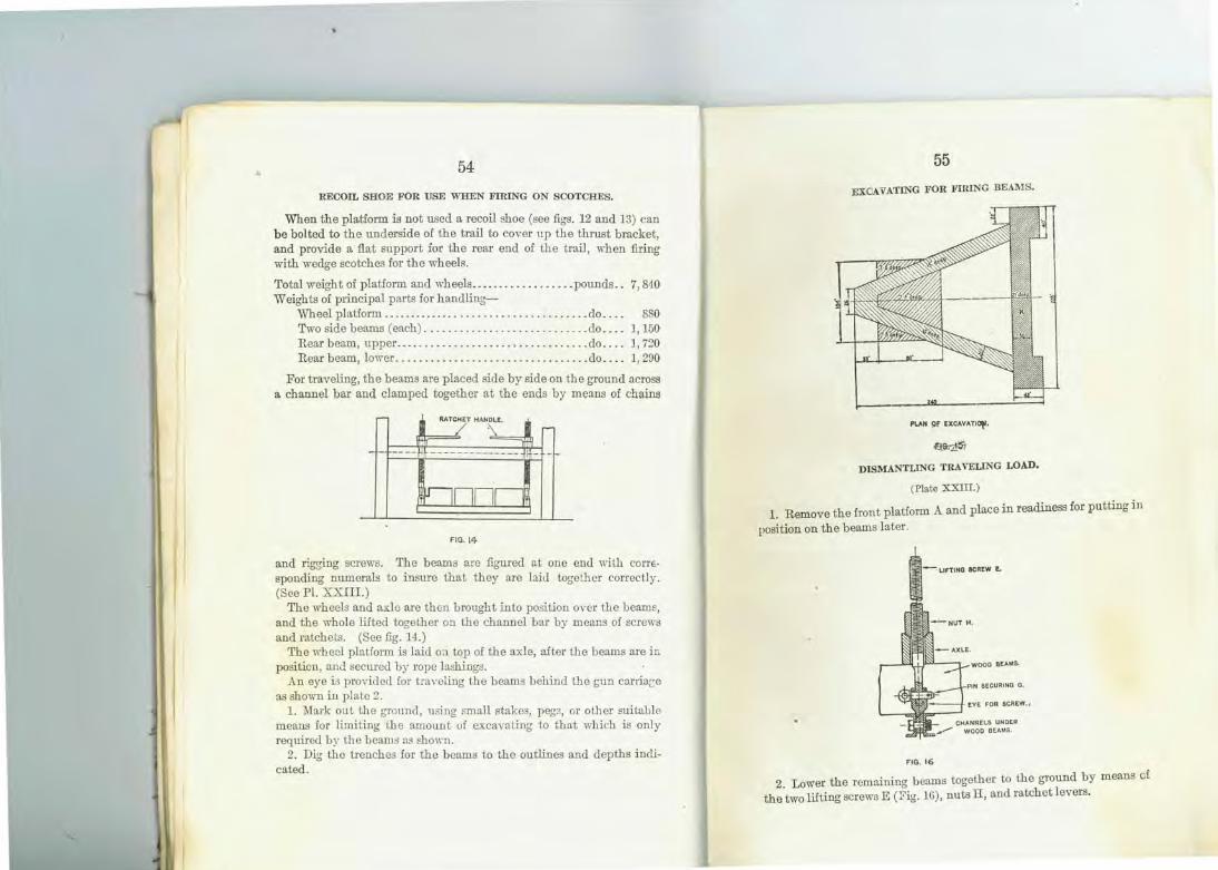
54
RECOil. SHOE FOR USE WHEN FIRING ON SCOTCHES.
When the platform is not used a recoil shoe (see figs. 12 and 13) can be bolted to the underside of the trail to cover up the thrust bracket, and provide a flat support for the rear end of the tr:til , when :firing with wedge scotches for the wheels.
Total weight of platform and wh eels ... ... ...... .. . .. . pounds .. 7, 840 Weights of principal pm-ts for hand ling-
Wheel platform ..... . ............ .. .......... ...... do.. . . 880 Two side b eams (each) ................... . ........ do .... 1, 150 Rear beam, upper .............. . ........... ... .... do .. .. 1, 7:!0 R ear beam, lower .......................... .. ..... do. . . . 1, 2!JO
For traveling, the beams are placed side by side on the ground across a channel bar and clmuped together at the ends by means of chains
- RATCHET HAN~, I / . ..... ffi
- -- --- ------- h- +
nn1 lr
FIG.l4
and rig.,cri.ng screws. The bemus ru·e figured at one end with cotT£· sponding numerals to insure that th ey are hid together correctly. (See Pl. XXIII. )
The wheels and axlo are then brought into position oyer the bemus, and the whol e lifted together on the channel bar by means of screws and ratch ets. (See fig . H.)
The wheel platform is laid 0:1 top of the axle, after the beams are in position, and secured by rope lashings.
An eye is provided for tra1·eling the beams behind the gun carria;::e as shown in plate 2.
1. Mark out the g1·ound, using small stakea, pegs, or other suitable means for limiting the muount of excavating to that "·hicb is only required by the beams as shmm.
2. Dig the trenchea for the beams to the outlines and depths indicated.
55
EXCAvATING FOR FilliNG BEAMS.
f>V.H 9F EXCAVATiot'•
DISMANTLING TRAVELING LOAD.
(Plate XXIII.)
1. Remove the front platform A and place in readiness for putting in
position on the bemus later.
FIG. 16
2. Lower the remaining bemus together to the ground by means of the two lifting screws E (Fig. 16), nuts ll, and ratchet levers.
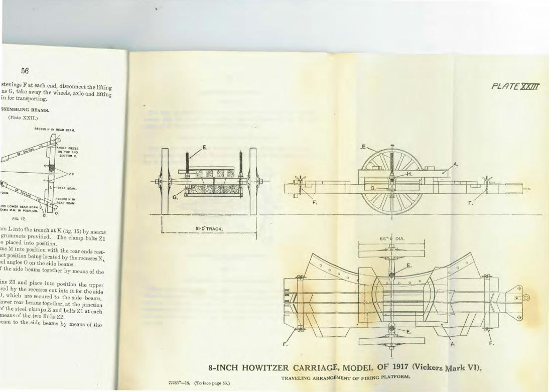
stenings Fat each end, disconn~t the Jiitinrr ?a G, take away the wheels, axle and liftin~ m for transporting.
3SEMBUNG BEAMS.
(Plate XXII.)
AECESS N IN REAR BEAM.
FIG. 17.
l.D1 L into the trench at K (fig. 15) by means grummeta provided. The clamp bolts Zl
•e placed into position. ms .U into position with the rear ends restbOt pcai tion being located by the recesses N Jel angles 0 on the siue beams. '· f the side beams together by me<~na of the
in~ Z3 and place into position the upper •red by the recesees cut into it for the side ), which are secured to the aide beams. lower rear beams together, at the junction of the steel clamps Z and bolts Zl at each means of the two links Z2. >eam to the aide beams by means of the
PL/ITEXX!ll
8-INCH HOWITZER CARRIAGE, MODEL OF 1917 (Vickers Mark VI). TRAVELING ARRANGE!\1£NT OF FIRING PLATFORM.
72283"-18. (To face page 56.)
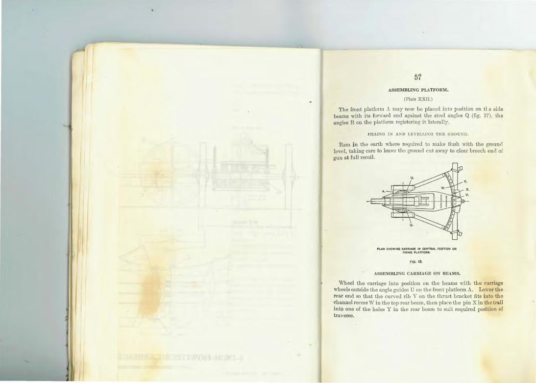
57 ASSEMBUNG PLATFORM.
(Plate XXII.)
The front platform :\. may now be placed into position on tl.e side beams with its fomard end against the steel angles Q (fig. 17), the angles Ron the platform registering it laterally.
FILLING IN -L'ID LEVELLlXG TJJE GROUND .
Ram in the earth where required to Dl!l.ke flush with the grounrl level, taking care to leave th e ground cut away to clear breech end oi gun at full recoil.
A.
f'LAN BHOWIHCi CARRIAGE IN CENTRAL X)StTION ON FlRING PL.ATFORIII .
FIG. 18.
ASSEMBUNG CABRIAGE ON BEAMS.
Wheel the carriage into position on the beams mth the carriage wheels outside the angle guides U on the front platform A. Lower the . rear end so that the curved rib V on the thrust bracket fits into the channel recess Win the top rear beam , then p lace the pin X in the trail into one of the holes Y in the rear beam to suit required position of traverse.

8-INCH HOWITZER CARRIAGE LIMBER MODEL (VICKERS). ' OF 1917
FRAME The limbe· · · £I r coruusts of a framework whl h .
anged steel connected by a trou h c co~priSes four futchels of aad by a plate in the center anf -shape~ splinter bar at the front futchels is riveted a steelli b h rea:. 'l o the back of the center . m er ook wrth a ke E h IS connec ted to the splinter barb d' · Y· ac center futchel
Y a ragonal stay. . AXLE A D WHEELS.
The axle lS of steel, circular in s . . passes through bearin!!'S f d . ectiOu, With special wheel arms It b b " orme m the futchel d . h .
y rackets, which are keyed to th l h s au Is eld in position o~tside futchels. The outer end of e a~ e ~ o.ulders and bolted to tile wrth sec uring pin. eac mm lB prepared to take a cap
The wheels are of steel 66 l'nch . eli · h ' es m amet · h · me es. A grease cup is attached t h eJ' avmg a tread of 6 . The wheels m·e h eld on the axle:~: bwheel.
pm which passes throu"'h the ca. d I y a drag washer, cap, and a by a split pin . " p au ax e arm and is h eld undern eath
, LIMDER CHEST.
Th~ li~ber chest is of steel and is bolte The lid Is hin"'ed at the front d d .to the top of the futchels Padlock " au secured m the rear by a h .
· asp an d The top of the chest is fitted with h
on the side to take an ax sh I andholds. There m·e also fittin!!'S · t • ove s, wr·enches tc Tb "' m ernally to carry tools, spm·e packin f . ' e : .e chest is fitted .perator, obturator, etc. gs or recoil cylinder and recu-
. DRAFT POLE. Tho hmber is equipped with a .
tnction specral cast-steel draft pole f • · or motor
(58)
:MISCELLANEOUS TOOLS AND ACCESSORIES.
PROJECTILE BEARER.
The projectile bearer consists of a steel porter bar with handles and a pair of tongs of the toggle joint type. It is used to carry the pro· jectiles from the supply to the loading tray .
PORTABLE AIR CO~IPRESSOR .
The air compressor is b olted to clips on the lower end of the trail when required for use, and is connected to the left air cylinder of the recuperator by me:1ns of a pipe. The piston is actuated by a crank shaft with winch handles transmitting motion to spur gearing.
The compressor is of the vertical two-staged type with high and low pressure cylinders. The low-pressme cylinder is provided with a suction valve fitted with an oil drip lubricator and is connected to the high-pressure cylinder by a short pipe fitted with an intermediate valve at either end . A delivery valve connects the high-pressme cylinder to the delivery pipe .
The cylinders are inclosed in a manganese bwnze tank, which forms a water jacket for cooling purposes. Tl1e tank is provided with filling and drain plugs, and must be fi lled oniy when the compressor is in use.
A dust cover and two lifting bars are provided with the compressor . Two compressors are furnished 1ritl1 each b:1ttery of fom guns.
OBTURATOR PRESS.
The press and gauge are for use in re-forming obtmators which baYe become distorted. 'rhe press consists of a steel body, shaped internally to suit the contour of the obturator and fitted with a steel coYer. The cover is seemed by means of a steel bolt with disk spring washer and cross handle. The bolt is provided with a square head , by means of which the press can be held in a vise while the cro s handle isrevolved when compressing or releasing the obtmator. A steel tommy bar is provided for use wi th the cross handle in compressing the obtumtor. Recesses m·e formed around tl1e periphery of the press so as to admit the application of the gauge for testing the thickness of the obturator while under compression.
The gauge is a fiat steel pl:lte and is used for testing the thickneRs of the obturator.
(59)

60 PORTABLE LIQUID PUMP,
This pump is used to fill the recoil cylinder and to charge the rectiperator with liquid. It consists of a cylindrical galvanized iron tank provided with a. lid. There are brackets inside the tank, in which the pump is secured by a bayonet joint. The pump proper consists of a vertical cylinder diYided into two chambers, in one of which works a packed plunger actuated by handle at the top. The lower end of the pump is perforated for the entrance of liquid, which enters into the plunger chamber through an inlet vah·e. The bottom of the second chamber is fitted with a deliYery valYe and its top end has a threaded delivery nozzle, to which is attached a length of flexible bose, which connects the pump to the recuperator piston rod.
LOADING TRAY.
The tray is of steel semicircul::u· in shape, fitted at the front end on the underside with a gun metal frame for engaging the lower interruptions in the breech opening. The rear end of the tray is tumed up so as to form a stop against which the base of the projectile rests when being carried in the tray. It is provided on the underside with two brackets for the bearers. The bearers are tubular in section and are riveted to the brackets at the inner end; the outer ends are furnished with supporting brackets to facilitate handling. The outer ends of the bearers are provided with leather handgrips and wood plugs. The bearers are connected and the right and left sides by glUt metal guide bar, which are shaped to rest on t].J.e side plates of the cradle to support the tray in the correct alignment for loading.
SYRP-\TGE FOR EXTRACTING LIQUID .
The syringe consists of a body and spout of tin. In the body works a packed plunger. Its capacity is one-tenth pint of liquid. It is used to extract a small quantity of liquid from the recoil cylinder after the latter bas been filled.
R,unrER AND SPONGE .
This combined tool performs the duty of a cleaner for the chamber in addition to that of ramm!.'r. The sponge portion consists of a bronze sleeve around which is fastened the sponge head, which is of maple. This bead is covered with a closely woven covering of carpet. The rammer is made of manganese bronze and when used is screwed onto the end staff. The sponge is fitted to the staff in the same manner. The staff is in three pieces, which may be screwed into each other.
MEASURE FOR FILLING R ECOIL CYLINDER.
. . d holds 1 gallon. There are ribs around This measure lS of tlnhia~h l t l pint one-half pint, and one-
h · 'd surface by w c quar ' ' d 'tl t. e IDSl e d Th lower end is provide WI 1 a t · t may be measure . e . quar er pm It . fitted inside with a wire gauze strruner. spout and cock. 18
FillE-CONTROL EQUIPMENT.
ARMY ARTILLERY.
Material. Number per bat
tery.
-------------ORD~A.J.~CE PROPERTY.
···-········ · ~~~~J~E;~~~: ::::::::::::::::::::::::::::::::: ~ ~ ~ ~ ~ ~ ~:::::::: ........ . Pe~IScope_azimutb inst trumdineornty. dra~V{.;g ·materiili:::: ........... · · ·•· · · · · · · · · Azunuthmstrumcn, or ·······- --··-------Set drawiny instruments .· ·· ······· ········· .... ··::::::: .............. .. .. · Seal~, _eq ua par~ m~nt&.;;,~i:;) ·grad~~ted ·i·~ i:D.illS ... · · · · · · · · · · · · · · · · · · · · · · · ~~~;~ r~e_t~r l~ng,dgraduated 1 to 20·'x_x_>:::::::: ::::::::::::::::::::: Range and aeflectton boar . · - -- · · · · · · · · · · · · · ........ ............ .......... . ~:~~;a~~!ill.d.e.rs; ·teiescoi>eS; ·illaciei iii1s·.· ....... ..•... · · · · · · · · · · · · · · · · · · ·
ENGINEER PROPERTY ·
··-····------ -· · · ·········-~t,!ill'!~~~~~~ :~~-e_s._.~:::::::: :: : ::::::::::::::::::::::: : :::::: ::: :: : :::::::: Ranging rods ...... ·--··· ·.th·d· ·UMt~r. opo~·sight, and telescope alidade .. · · Plane table, 0.24 by 31, wt ec . , .1 ..... ...... . .. ~~~~~~-~~~~~·- ~-~,~~~~ _r~~~~~~-~- ~ : :: : :::: :: :: ::::: :::: .......... ... .
SIGNAL CORPS PROPERTY.
Amplifiers, type 3, terrct complete "'ith ~ Yolt and~~~~-~:.~~~~~:~ -~~~~~:::
~~i: ~~~~~r:~~~~~:_:_~::::::: :::::::::::::: ~ ~ ~ ~::::::::::::::::::: ::: :::: Batteries, extra tunj!stcn, t)1>e '\.ii:i · · · .... · · · ....................... .. Batteries, extra EvcJTead~~ N~. • 1 I m.p.s ·......... . ....... · · · · · · · · · · · Batteries, mrtra Fda., T. m: Sli!Illl a · · · · --.: ·. ·:.:::::: .................. . Bells, vihratmg, 110 cbm. 1o volt .. ..... ··· ···· . . ... .... . .
~i~~:;~eTt ..... ffi., :: : H Barometer graduated, mJ!lime~e t s by 5 centimeters ............. .. . .... . Cross arms, 1 meter by 10 cent lDle er .......... . .. ..... . Flash lights, electric, complete.d. .. i j-'~~ boardS.:::::::::: .............. ····· Fuses, extra 1-amfere, for 4 an 1 1 · ......... . .......... . ... .
~~~~l~~~~~:~~~~~~~~·:··.·::::: : ::::::::::::: -::::::::: :·. ·. :·.::: ::::: ·.: ·.::
4 1 6 2 2 1 1 1 3 1
12 1
2 1 4 1 G 1
1 R 1 2 9 24 5 2 1
15 10 4 1 ~ 1 ~
140 9
40 4 1 2
62
FffiE-CONTROL EQUIPMENT-Continued .
ARMY ARTILLERY-Continued.
Material.
SIGNAL CORPS PROPERTY--<JOntinued.
eJri~rn~~ft~ ~: ~ ~ ~: ~ ~ ~: ~ ~~ ~ ~: ~ ~ ~: ~ ~ ~ ~: ~ ~ ~: ~ ~: ~: ~ ~:::::: ~ ~:: ~ ~ ~ ~::::: Insulators, wooden 1;nob, French type, 2.5 em. high, with nai ls ............. . I;lsulntors, wo.ode~ knob, French type, 4.5 em. high, with nails ............. .
~~~~~iE~~~~~~e !::· ~-:~~~~~: _:::: :::::::::::::::::::::::::::::.::::: ~~~~~h';;~:s~~~~~~ .8-~:~~:: :: :::::::::::::::::::::::::::::::::::::: :: :::::: it:;,':rs1?o~~~~~gru-~~e-ry," cli~;n.oi)ci "sliaj)e<i; ;;ciiarent. ruii:~s· "J35"o "rui(i "4"5' •.
each side 9 meters long, white ......................................... _ .. . Panels, for heavy artillery, diamond shaped, adjacent angles 135• and 4;;•,
each stde 9 meters long, black . ...... ......... ....... . ... ........... .. ..... .
P~~~·s{~~ ~~~fe:';f:;i~~?'{vg:~~~~ -~bap~_d,_ ad!a~~~t- a_n~~~~ _1_35~ _t\Dd. ~5-·~. p:~l~·sl~~ ~~!le~-r~~~~ybl~~~~~-~ -~~p-ed,_ ad!~~e~t .nn~~~~ 1~5~ .nn~. ~5-·~. Panels, heavy artillery, rectangular, 9m. fly3m.,10cm. diameter (sapinottes),
white ...... . . ............................................................ ·· Panels heavy artillery, rectangular, 9 m. by 3 m., 10 em. diameter (sapinot-
pJ;;2; ~~- :·:.·.·.·::: :::: :.· :.· :: .· ::::::::::::::::::::::::::::::::::::::::::::: Projectors, 14 em. (pack~d 3 in cases with batteries), case ................... . Pulley blocks, double"" E . No. 760,330 ....................... . ......... .. .. . Receiving sets~ype "A," complete ...... . ........... . .............. . ..... . . .
~~~~ ~~;;~ t~r.e~~~~te~r~-:-::::::::::::::::: ::::::::::::::::::::::::: :: Screws, lag, 1u mm. by 10 em. (for cross arms) ......................... . .... .
~~~~ ili~~1;,i.~:.by·~-~-~-~~~~::: :::::::::: ::: :::::::::::::::::::::: Staples, insulated, Blake .. ....... ... .......... ... .•.•. ...... ... .. ........... Switchboard telephon•, 4-line monotype ...... . .......•... ... . •..... ..... .... Swttchboard telephone, 12-line monotype . ......... . ......... . .............. .
~~Pc~~%~~~Jg~~&~~~: :: :::::::: :::::::::::::::::::::::::::::::::::::::: Watches, wrist, luminous, with wristlet ............. . . ........ . • ............
~;~:; g~;t'e~.rf.1T,s;,,TI~;,~~ jgf:.-_:: :: ::::: :::::::::::::::::::::::: ::: :::::: Thermometers, Grad. Centigrade, Fahrenheit ... .. ........ .. ........ ... ..•.. Poles, 2.3 to 2.5 m. long, 10 em. diameter (sapinotte) ........ .. . . •... ..... _ ...
Numbor per bat
tery.
1 16
100 23
220 GlO
8 5 5 8 1 2
3
3 !OD
I 2 I I
a;; 4
300 2 1
400 2 1 3 2
1?. 5 l 8 2
250
The fire-control equipment (as listed) is carried in compartments provided for the purpose on th e telephone truck and reel truck, model of 1918. The trucks form part of the equipment and, to6ether with the fire-control instruments for battery and h eadquarters company, arE> described and illustrated in Ordnance Office Pamphlet, Form No. 1796 ,
63
Fir Control Equipment for Field Artillery." The ''H~ndbook_ of d' :the headquarters company of a regiment of field eqmpment lSSUe
. . r t din Form No. 1796. artillery lS IS ~ tailed description of the method of disassembling and ~ c~m,;let: daerent instruments is given in Ordnance Offic~ Pam
adjustm" th "Instructions for the Care, Preservation, Repan, and phl_et No. 1795£ •T .... ents for the Fire-Control Systems for Coast and AdJustment o n.~L. urn F" ld Artillery." · will b -
Ie . semblin"' of instruments ex.cept as prescnbed . .e per ~o ddis~he disa;,embling of instruments allo"·ed her~m must _be
m1tte . · sioned officer. D1sassembhng
~U:e~!ftt~'~ t~e ~::~~~:t0i7~5co= be done only by officers an•l
employees of the Ordnance Department.

EQUIPMENT.
The foll owing table sets forth tools and accessories and spare parts for one 8-inch howitzer battery on war footing. The right-hand column shows in general where each article should be carried, but the battery commander may use his discretion as to the disposition of many articles for which no particular fitting or receptacle is provided.
(G4)
65
t l nd accessories of one 8-inch howitzer bat Statement of sp~~::~J.et~/19~7 (Vickers, Mk. VI).
Article.
TOOLS A-"\'1> ACCESSORIES FOR HOWITZER.
~1E~fb1~1tr;:: ::::::::::::::::::::::::::::::: Thickness gauge, obturator •... ·· · · · · · · · · · · · · · · · · · · · Bronze reamer primer seat . ... ..•...... .... •........
l~IP l : Wire-cutting pliers, S.inch · • · · · • · • · · · · · · · · · · · · · · · · - ~ Hand mallet . . . .. . .. ............. ··-·-· · · · · · · · · · · ·
~!l'r!~,;:tiaffiffiei-::::::::::: ::::::::::::::::::::::: File ~hree-corncred, 8 inches long, w1Lh handle ..... File; flat, 8 inches long, dc~d smooth, wuh handJo . . File round, second cut, 8 mches long . .. ·--········· File; round, smooth, S.mch ..•... .. .. -.- · · · · · · · · · · · · File handles ............ .. .. - -- -- · · ·-- · · · · · · · · · · · · · · File, half-round, smooLh, 8 inches long .. ---.·-- ·· ··· File, pillard No.6, 6mchcs long •.•. .... --- ••.. ·· ···
rn:'c~~~~o~~~~'k.~~---~::: ::::::::::::::::::::::: Obturator press, complete . .......... ·· ... · ··· ······ Muzzle covnr ••••• . .. ............•• ... . . ·• ·• • · · · · · · • Breech CO\•er . ...•. ... ...... ·-. · · · · · · · · · · · · · · · · · · · · · Toolldt, No. 1. . ... .. ............... . - · · · • · · · · · · · · · · Fileldt . ......... . . .. ................. ·· · ···· ···· · · · Bronze reamer case . . ..... - .... . ---.---- ···· -·-··-·· Cover for gun •.•....... • ..••.... ...... ...... .. · .. · · · Spare parts, pouch and rolls ... . . .. · · .. · · · · · · · · · · · ·
SPARE PARTS FOR llOWlTZI:R.
Breech block rotating cam ......... ·-······ · ········ Rotating cam and control arc screw ... · . · · · · · · · · · · · · Control arc .. .. ... . .......... . ... ---··· · ········· · ·· Rotating cam screw ............ ---··· ··········· ·· · Lever bearing_ .... ......... .... ..... ····· ·· -----·--Crank shaft with nut and split pin ... . -·········· · ·· nearing washer .. . .•...... .•. . . .... · · · · · · · · · · · · · · · · · Crosshead .. . ...... . ...... .. .. .. ... : -- ·. · · · · · · · · · · · · · Lever hearing seeming bolt and split pill.---······· Hinge pin and split pin ..... . . -. · .- · ··············· · Lever catch plate screw . ........ - -. • · · · · · · · · · · · · · · · · Spring retaining block securing pin . - . · · · · · · · · · · · · · · Lever catch . . . .. .. . ..........•. •... . .... -.-. · ·- ·- · · · Catch plate ............... -.-·.···· · ·········· ·· ···· Lever catch retaining spring block .• -.. - · -- -- · · · · · · · Lever catch spring ...•.........• .• .. -· ·---· ··· ··· ··· Leverarm . . . . .. ... •••• ...••.. ..••.................. Obturator pad. • .• ..... . -----·- · ········· · ·· · · ······
Number per
battery. Where carried.
4 In limber box. 4 Do. 4 Do. 2 In supply truck. 8 In l.inlber box. 4 Do. 4 Do. 2 In supply truck . 4 Inl.inlber box. 4 Do. 4 Do. 4 Do. 4 Do. 4 Do. I Do. 2 In supply-truck 8 In limber box. 4 Do. 4 Do. 4 Do. 4 Do. 4 Do.
28 Do. 4 Do. 4 Do. 4 Do. 4 Do. 4 Do. 4 On muzzle. 4 On breech. 4 In limber box. 4 Do. 4 Do.
! g,n J::b·er box.
1 In supply t ruck. 6 Do. 1 Do. 1 Do. 1 Do. 2 Do. 4 Do. 2 Do. 2 Do. 1 Do. 2 Do. 2 Do. 2 Do. 2 Do. 1 Do. 4 Do. 1 Do. 8 Do.

66
Statement of spare parts, tools, and accessories of one 8-ineh howitzer batten), model of 1917 (Vickers, ID". VI)-Continued.
Article.
SPARE PARTS FOR JJ DWITZER-continued .
t~~;~it·n · : 0 btura tor spindle spring . .. .. . .. . ... . . . . . . . .. ... . .. . 0 bt urator spindle vent bushing . ... . .. . . ...... . . . .. . Obturator spindle plug ... . . ... . . . . . . ... . . . .. ... . .. . Obturator spindle p lug gasket . . .. . ... . .... . . .. . .. . . Obtura tor box, complete . . ...... . . . . . .. . .... . . . . .. . . Breech block ..... ... ... . . . ... . . . . . . ....... .. .. .. .. . B reech block roller . .. .. ..... . ... .... .. ... .. . . ... . . . Breech b lock roller axis pin with split pin . . .. .. .. . . Breech block retaining plate .. . . . ... . ... . . . ... . . .. . . Breeqh b~ock retaining plate actuating pin with
Number per
battery.
(' )
6 4 4 4 4 4 4 6 4 4 2
2 sprmg n vet.
R etaining plate actuating pin retaining rivet.. . ... 4 Carrier. .. .. .... . .. . .... .. ... . ... . .... . . . . . .. . ..... .. (1) Handy oiler (Bennet) .. . . . . . . . . . . ..... . . . . . . . .. .. . .. . . ..... . . . Breech mechanism complete •.. . ....... . ... . . . . . . . . (3)
Retainer pin with split pin . . . . . . . . .. . ... . .. . .. .. . .. 4
ifu1r~i~~i~~ ~ ~ ~ ~ ~ ~ ~ ~ ~ ~ ~ ~ ~ ~ ~ ~ ~ ~ ~ ~: ~:~ ~ ~ : ~ ~~ ~~ 1~ Firing mechanism b lock. . . ... . . . .. ..... . . . . . . . . . . . . 8 F iring mechanism block handle. .. . . . . . . . . . . . . . . . . . • 8 F iring mechanism housing. ... . . .. . . . . . . . . . . . . . . . . . . 6 Firing mechanism safety plunger h ousing. .... . ... . . 2 Firing mechanism safety plunger cam. . . ... . .. . ... .. 2 Firing m echanism safety pl unger spring . .... .... .. . 6 Firing m echanism safet y plunger . . . . . . . . . . . . . . . . . . . 6 Safety plunger guide screw. .. . . ... ... . .. . ... . ..... . . 2 Percussion hammer... . .. . . .. . . . . . . . . .. . . . . . . . . ..... 4 Percussion hammer lock bolt ... . . . ........ .. . .. . . .. 1 Percussion hammer lock bolt spring. . . . ...... .. . .. . 1
~~;~u~~~n"E~~:; 1s;~~'~oii si~ri:::: : :::: ::::: :: :: ! Percussion hammer operat ing sha ft. . . . . . . . . . . . . . . . . 1 Percussion hammer operating sha ft collar. .. . . ... ... 1 Percussion hammer operating sha ft collar detent. . . . 1 Percussion hammer bearing bracket •. .. ...... . ..... (' ) Primer seat p lug ... . .. .. ............... ... . .. . .. . .. . Firing pin spring .. .. . . . .. .. ....... .. . .. ......... .. . F iring m echanism block latch . .. . ..... ... . . ... .. . . . . Firing mechanism b lock latch spring . .. . . . . ... . ... . . F iring m echanism block latch spring h older .. . ..... . Firing m echanism b lock latch h older ..... ... .... . .. . F iring m echanism block mtch holder screw .. . . .... . Firing mechanism block la tch bolder h andle . . . .. . . . Firing mechanism housing screw . .. . ... . . .. ______ .. . Firing mechanism block safety latch bracket ...... .. 1
I 1 for 2 batteries. • Includes fi ring and percussion mechanism complete.
8 12 2 6 2 2 8 2 6 2
Where carried.
In supply truck. Do. Do. Do. Do. Do. Do. Do. Do. Do. Do. Do. Do. Do. Do. Do.
Do. Do.
Do. Do. Do. Do. Do. Do. Do. Do. Do. Do. Do. Do. Do. Do. Do. Do. Do. Do. Do. Do. Do. Do. Do. Do. Do. Do. Do. Do. Do. Do. Do. Do. Do.
• 1 for 1 battery. • Screws included.
....
67
S ta tement of spare parts, too ls, and accessories of one 8-inch howitzer batten) , model of 1917 (Vickers, Mk. VI )-Continued.
Article.
TOOLS .oL';D ACCESSORI ES FOR CARRIAGE .
l~l!t ::: : l •rool for withdrawing split pins . . . . . . .. .. . .... . .. . . .
~lt:i : Tommy bar, 8-lnch . .... . . . .. . .. .. . ... .. . . ........ . .
~.!~~J.~, : : Spanner No. 24 ..•.• ••.•...• • •..• . .... . .. • ....• .• • •.
§g~~~~W~c_r~: : ::::: : : : :::: :::::: : :: ::::: :: : : : ::
~5[~ ~~i~~~~ ~ ~ :: ~ ~ : ~~ : ~: ~ ~ ~ ~~ ~ ~ ~ ~ ~ ~ ~ ~ ~ ~~~ ~ ~ ~ ~ c~ adap tor · · ··· · ·· · · ·· · · ·· · · · ·· · ·· ·· · ······ · ··· · · A a~tor prossure gauge . . . ... .. .... ..... . . . . • .. .. ...
~~~~~~f~r.:o:r~ ~ ~ ~ ~ ~ ~ ~ ~ ~ ~ ~ ~ : ~ ~: : ~ ~ ~ ~ ~ ~ ~ ~ : ~ ~ ~ ~ ~ Washer, ping adaptor. . . . .... . . . . . ... . ... .. ..... . . . .
~~~· :: : arn ajje spare-part pouch ... . ... .. .... . . ... .... .... .
Tnmruon roller-bearing pouch ... ... . . . .. . . . . . . .. . . .
i::b~i~~~~p~~'W8: a.· .·:::: :: :: : :: :::::::::: ::::::: Case for lubricating can . . .. ... ... . ... . .... .. . .. . . . . . Grease box, 3-pound . . .. . ... . . .... .. . .. .. . . . . .. . .. . . Clinometer, in case, assembled . . . . . .. . . .. . .. . . ... . . . Air compressor, portable ...... .. . . .. . . . . .. ..... .. . . . Air compressor connections ... .. .. . ... .... .. ... .. .. .
~~~=·gb~~li ::: : : : ::: :: ::: : :: : : : : ::: : : :: : : ::::: ::
Number per
battery. Whore carried.
2 In supply t ruck. 2 Do. 2 Do. 2 Do. 4 In limber box. 4 Do. 4 Do. 4 Do. 4 Do. 4 Do. 4 Do.
16 On t rail. 4 In limber box. 4 Do. 2 In supply truck. 2 Do. 2 Do. 2 Do. 2 Do. 4 Inlimber box. 4 Do. 4 Do. 4 Do. 4 Do. 4 Do. 4 Do. 2 In supply t mck. 4 In limber box. 2 In supply truck. 4 Do. 2 Do. 2 Do. 2 Do. 2 Do. 2 Do. 2 Do. 2 Do. 2 Do. 2 Do. 2 Do. 2 Do. 4 On sights. 4 On t rail. 8 Do. 4 In limber box. 4 Do. 4 Do. 1 Do. 4 Do. 4 On limber box. 4 Do. 4 Do. 4 On t rail . 2 In supply truck. 2 Do. 4 Do. 8 Do.

68
Statement of spare parts, tools, and accessoms of one 8-inchhowitzer battery, model of 1917 (Vickers, Mk . VI)- Continued.
Article.
TOOLS AND ACCESSORIES FOR CA.I:RlAGE-contd .
Number per
battery.
Cover for air compressor . : . . ...... . .. . . _ . _ .. . .. _ . _ . . 2 Lilt ing bar for air compressor . . _ . . .. . . . . . .• . .. . __ . . . 4 P roject ilc bearer ... . ... . . .. . . . . . . ..... . . . . . . . .. __ .. _ 8 Air reservoir, fllling recupera tor • . . . . _. . . . . . . .. . . . . 4 Air r eservoir adapter . . . . . . . . . • . . . . . • . . . . . . . . . . . . . . . 2 Canvas roll for trunnion rollers ... . _.. . ..... .. . . . . .. . I Pu'!'p, portable, liqu!d . .- . . . . .. _ _ . . ... _.. . .. . . .. . .. 2
~~~J?~~~f~e:-/~~~~ : ~ ~~: :: : ~ : ~ ~~ ~~ ~ ~~ ~ ~ ~~ :~: i Cose, steel, for panoramic sight . . . . . .. . _.... .. .. . . . . . 4 Rammer ... ---._ ..... ____ . . ..... __ . .. ....... ... .... . 4
fo':~§ i:i.irrow-.· ~~ ::::::: :::: :::::::: :::: :: ::::::: : · · · · ·· · ·4· Gunners quadrant, model of 189i, with cosc '· . ..... (') Oilcan................. .... . ... . ........... .. ..... . 12
~Jlr~~~~:~~~: :: : : ::::::::: :::::::::::::::: :::::::: ~ Carriage sparo parts roll . .. .. . . . .... . .. . . ... . . . . . . . . 1
TOOLS AND ACCESSORIES FOR Lnl BER.
Obturator box, complete . . • . . . ...... . . ... . ... _
[~~~l¥~~~~: ~ ~ : ~ ~ ~ ~~ ~ ~ ~ ~ ~~ ~ ~ ~ ~ ~ ~ - ~ ~~ ~ ~ ~ : ~ : : Lao tern straps ........... ........... . .... . .. . • . . .. . . Lim her spare part pouch . .. ... . . . .. . . . ..... . .. . . .. . P ole prop .... . .... . . ... ... . . . .. ..... - -- -.... .. . . ... . Limber spare Parts roll ... ... .. .... -- . -. .. . .. . .. . . . .
StraNt~nket (paulin) . .. . . . ..... --. ... . -.. - -- - . - -- . . 12 Ax. .. . ........... . . . .. . .... . . . . ..... . ..... . . . .. 4 Grease box...... .. .. . . . ... . . . . . .... . .. .. .. .. ... 4 Pickax.......... .. . ... .. . . . . .... .. . . .. .. ... . . . . 4 Shovel, short .... . . . .. . .... . .... . ... _ . . . . . . . . . . . 4 Pick mattock .. ..... _ . . ... . _ ... . _. .. . ........ . .. 4
Obturator box (this box is a spare acrcssory ) . . ... . . 1 Picket rope ....... . . .. . __ . . . . . • . . . . . . . . . . . . . . . . . . . . . 4
TOOLS AND ACCESSORIES FOR Flll!XG PLA'r FORM.
Spanner No. 22 •.. • • .. . ................. _ .... . ... ..• SJJanner No. 25 • ... ........ .. . . .. .. . . . . . . .... ... ... . Picka.'< ...... . .. .. ... .. . . .... . . . . . . . . . . .... .... .... . Short-handled shovel. .. . . . ...... . .. . . . . . . .. ... . ... . Hatchet .... .. .. ... . : . . .. . . . . ...... . . . ...... . .. . . . . . Ax .•......... . . .......... . . . . .... .... . ....... . . ....
~?~~~~-~~~-~~~~ ~::: : : :::: ::: : : : ::::::::::: :::: Spanner, 26-inch. . . ... ... .. . ... . . . . .. . . . . .. . ... . .. . . Tommy bar (spanner No. 26), 13-inch . . • . . . .. . . ... ..
1 'l' wo per battery.
4 4 4 4 4 4 4 4 4 4
Where carried .
On air comnrC'ssor. In SUPP.lY tr uck. On trrul. In supp ly t ruck.
Do. Do. Do. Do.
On t ratl. Do. Do.
On carriage. On trail.
In limber box. 0 n carriage. On vehicles. On carriage.
Do. On t rail. In supply t ruck.
In limber. In limber box. On limber.
Do. Do. Do.
In limber box . On limber. In supply truck.
On limber. Do. Do. Do. Do. Do.
In supply t ruck . Limber.
In limber box. Do.
On limber box. Do.
Outside of limber box.
On t rail. On limber. In limber box.
Do.
69
Statement of spare parts, tools, and accessories of one 8-i:tch houlitzer battery, model of 1 ~17 (Vickers, 1lfk. VI)-Contmued.
Article. Number
per bat tery.
Whore carried .
TOOLS AND ACCESSORIES FOR SUPPLY TRUCK.
on can, it-gallon (recoil cylinder ) ••. . . ..... . .. . ... . . Oil can, 7~gallon (glycerm) . . . ..... .. ...... .. . . . .. . . Obturator box, complete .. . ..... . .. .. ... . .. .... . .. .
SPARE ACCESSORIES FOR CARRI AGES AXD SPARE PARTS OF ACCESSORIES.
Clinometer assembled, in case ..... . . . . . - .. .. .• ------Chest for spare sight . •. . .. . . . .... ... . . --. . ... -•. - --· Air compressor connections . . . .. . . . . . .. . . .... . . •.. --Chain cap square, pin k ey . . .. .... -.- . . ... -.. . . . .. - . Chain; lock!ng plate, l~ft-hand recu perator -. . .. . ... . Chain, locking plate, r tght-hand recu pera tur .. . . . . . . Chain pin air-compressor t ratl. .. ......... . ..... .. . Chain; lock bolt t.ra veling lock . ... . . ..... .. ..... . .. .
SPARE PARTS FOR CARRU GES.
Rccupcrator. L ocking plate, air plug, right band .. . . . ---.- .. .. . . . . Washer air plug, mr reservotr, n ght-hand s tJe .• .. . . Locking plate, !ront nut air resen 'oir .. . . . . ... . . . -.. Looking plate rear extenswn plug .. .. ... ... . . ... . . . Packing glaod, front plug reouperator . . . . . .. . . ... -.. Packing gland buffer plug .. . . . .... .. . . . . .. ...... .. . Locking plate front plug recoil cylinder .. -- . ..... -. . Locking pla te front plug .. . . . ... - . . . ... . --.- .. . . .. . . Locking pla te recuperator liners, rear end ...... . . . . . Studs for locking plates . . . . ... .. . .... . ..... . ..... .. . Neck ring air val ves .. ...... . . . ..... ... .. -...... .. . . Nu t spindle air valves ... ... ... .......... . . . ... .... . Filling plug .. . . _ ........ . ... .. . .... .... ___ .... . .... . Adapter front plug . .. . ...... . .. ......... . .. . . .. -. . . Stud locking plate, rear .. .. . . . . . .. .. . ...... . ..... . . . Leather ring, front plug recuperator . ... . . ... .. . -- . -Breechnut .. . . . ................ . ... .. .... .. . ... ... . Recuperator rod nut !ron t .. . .... . . .... . . .. .•••.. -. . Collar recuperator rod front .... .. . . . ... ... .. ---- --.-Rear n ut, recoil cylinder piston rod . ... .... .... .... . Frnntnut, recoil cy Un der piston rod . ...... . .... . .. -Bearing strip for p iston . ... . . ... . .... .. -. ..•. . .. -. . -Alr and filling plugs lor recoil cylinder . . ... . .... . .. . Scr~w securing pin bearing strip .. . .. .. . ... . . . .. -.. . Sprmg . . . .. . . .... .. . .. ... . . .. .... . . . . . ...... . .. .. .. . P acking, garlock, rings .• .. . . . . . . .. . .. . ---- - - . --- -- -Recuperator rod leather, 0.187-.'.r by 3 . . . . .... • . .. ... Collar recuperator rod, 0.187,0. o y 2.5 . . . ..... .. - -- . . -R ear nut recoil cylinder piston rod, 0.212,0. by 3.5 . •. . Fron t n ut recoil cylinder p iston .... . . .. . .. . .. .... .. . R ing, packing for ai r valve (in t in box) . . . ...... . .. .
Cradle.
Nuts, binge bolt cradle . ... .. .. . ... . . . . .. .... . ... --. Screw, !or securing leather pad .. . •. . . .. . .. . .... -- ---Trunnion roller bearinglicomplete . . .. . .. .. . . .... - -. -Roller path trunnion ro er bearing, ou ter . ..... . ... . Roller path trunnion roller bearing, inner ......•... . R oller, trunnion bearing .. . ..... .. . . ....... . . .. . . . . .
72283 ° - 1R-6
In supply truck. Do. Do.
1 In snpply truck. 1 Do. 1 Do. 2 Do. 1 Do. 1 Do. 1 Do. 1 Do.
In supply truck, l 'J Do. 4 Do. 2 Do.
16 Do. 8 Do. ~ Do. 4 Do. 4 Do. 2 Do. 4 Do. 4 Do. 4 Do. 2 Do. 2 Do.
2 1 Do. 2 Do. 8 Do. 4 Do. 4 Do. 4 Do. 4 Do. 8 Do.
12 Do. 8 Do.
16 Do. 8 Do. 4 Do. 4 Do. 4 Do. 4 Do.
2 Do. 1 Do. 4 Do. 2 Do. 2 Do.
64 Do.

70
Statement of spare parts, tools, and accessories of one 8-inch howitzer battery, model of 1917 (Vickers, Mk. VI)- Continued.
Article
SPARE PARTS FOR CARRIAGES-{lOUtinued.
Variable recoil gear.
Pin axes, rear eonnerting rod and spli t p in ... . .. . . . . P in spindle cut-off and split pin ..... ... ....... ..• ..
Elevating and traversing gear.
Pivot nut gear hoc . .............................. . Rail thmst washer ...................... . .... .. . . .. . Nut spindle-worm elevating and split pin .......... . Nut pinion elevatine: and split pin .. . . .. . .... . ..... . Locking-plato bushing ... ....... . .... .... ..... .. .. . . Screw pointer, traversing ... ..... ... .......• . .•..... Collar securing sight-operating bracket ..... .... . . .. . Traversing pointer screws . ......... . . . . . .... .. .. . .. . Traversing pivot nut top carrier . . . .... .. ...... . ... .
Quick-loading gear.
Bushlnl( bracket plunger ...... . . . . . ....... . .... . . . . . Pin rod fork end "front and spli t pin ...... ... •. .. . . . . Fork end front rod ... . . . . . ... . .. . ... . ... .. •... .... .. Fork end rear rod ....... . . . .. .. . .. . . ........ . ...... . P in rod fork end rear and spli t pin . . •. .. . ..... . ..... Nu~ for plun~;er brac~et ............. . ... .. . ..... .. . Spnng for qmek-loading gear . . ..... .. .... .. •... . . . .
Top carriage.
Locking screw key pin ......... . ........ .. ..... .. .. .
Traveling lock .
Locking pin, trail t ra>eling lock • . .. ........ . .. . ••. .
Bmke. Brake blocks • .. .. .................... . .. .. . .. . . ... . Nut, spindle and brake gear. .. .. .. .... .. .......... . ·washer, spindle brake gear . . . .. . ... .... . ••. . . . ..... Coach screw, brake block .. . . .. ... . .. ..••. .. . . .. .... Nut, pin brake gear and spli t pin . . . . . .. . .. ... ... . . . Nut, pin hanger and split p in . .. . . ..... . . . ... . . . ... . Nut, spindle l1rake gear .... . .... . . . .... . . . ... . .. .. . . Bolt brake bracket .... . ..... . .... . .. . ..... . .. .. . . . . . Collar rocking pin .. . . ... .. . . . . ... . . .. . . . . .. .. . . . ... .
Trail. P in, T draft. ...............•................ . .. . •• . Nuts, axle bolt (sets) .... . . ......... . ..•.•.. . . . . .. ..
~~~e~~~o~f:.~~~~~: ::: ::::::::::::::::: :: ::: :::::: Wheels, cnrriage, complete . . .. . ... ... . .. . . ... . .... . Pin, sccurin~ nir compressor, with chain . . . ..... . . . . Bolts, securing angle stiffener to spade ... . . .. . ••.. . . Nuts1 for holts .. . .... ... .. . ....•... .. ........... . .. . , ChecK nuts .. . . . ... ... . .. . .. . .... . .. . ...... . . . . . ... . Locking pin, trail1 firing pll\tform ...... ... ...... . .. . Washer, t ransom nolts ......... . . . . .. .... . ... . . .. . . . Socket for locking pin, trail. . . . . . . . .. ............ . . .
Number per
batt ery. Where carried.
4 In supply truck. 4 Do.
4 Do. I Do. 2 Do. 4 Do. 2 Do. 4 Do. 4 Do. 4 Do. 4 Do.
I 4 •1 4 4 4
I2
2
12 2 6
12 4 4 2 4 6
4 I I
18 2 4 8 8 2 2 2 4
Do. Do. Do. Do. Do. Do. Do.
Do.
Do.
Do. Do. Do. Do. Do. Do. Do. Do. Do.
Do. Do. Do. Do. Do. Do. Do. Do. Do. Do. Do. Do.
71
S t if pare parts tools and accessories of one 8-inch howitzer bat-tatemen ~~. model 0j 1917 (Vickers, Mk. VJ)- Continued .
Art icles.
SPARE PARTS FOR CARRIAGES -continued. Load-ing barrow.
Loading barrow, complete .... . ....... . .. . ... ... . -. Sight.
~N::~ff~fi~~:::-~-~ -:-:-:-:-: -:-:-: -:-:-:-:-:_: _: _:-: -:~-: :-:~_::~:: Bolt for gear case 6.2 i on~ . ... ... .. .. .. -- ------- --- - -Nuts for gear-casing bolts ... . .. .. ...•• .. ---- -- -- ----Bolts for gear casing ... .. ... . . .... ------- . . •· · ·· ····
S plit p ins.
8:gg~& ~; t~ ~ : ~: ::: :: ::: ::::::::::: :: :: ::::: ::::: : 8:mi~~~~~:: : : ::: : :: ::::::::::::::::: :::::::::::: O.I87-.'J by 3.25 ...... •• .. .... . ....... . .... . .. . . ... .. .
Button he3d: Rivets.
8:~5bJ'ii~~~~t.ill (i _·::::::: ::: :: ::::::: ::: ::: :: 0.437-i. by 2.25, pound . . .. .... . ... ... ... . . .. . . . .
Co~t~~~ ~~';d~ · ... ...... ...... .. .... ... .. ..... .
~:1~~1!.~~~~~~~ ~ ~ ~ ~ ~ ~ ~ ~ ~ ~ ~ ~ ~ ~ ~ ~ ~ ~ ~ ~ ~ ~ ~ ~ ~ ~ 8:g2~),~?,0:a'u~d ::: ::::::::::::::::::::::: :: ::: 0.75 by 3.5, pound .. .......... . . . .. . .... . . . . .. . .
CARRIAGE SPARE PARTS CARRIED IN LEATDER POUCD. Fiber washer, air and filli ng plug ........ .. . .. ----.-Leather washer plug adapter front plug ... . . ...... --Spring recuperator gland ... •. .. .. .... - -... ---- ----· · Spring t hrott le Yalve . .. .... . .. ... . .. ---- -- ·- --- - -· · Adjusting plug retarding . . ••. ... . ... ... . ... --- ----- -Washer plug recupcrator ... .. .. .. . .... - -- ---- . . . . -- -Washer plug retarding .. .. .. ...... ·: . ... . . . - .. .. . . . -Pacldng, front plug recuper~tor CJ:lmdcr. ..... -- -- . . Packing front plug recoil c~ lmder . .... . ... . ...... --Spring1 recoil cylinder . . . . .. . .. . .. . ---- --- --- ··· · · ·· Joint rmg, steel.. ... .. . . . . ... .. . .. ... -- -· ·· ·· · · · -- --
~~~~~~,;lg~~~-~r.-.-.-: : : :::::: :: :::::::: :: ::::::::::. Screw secw-ing bracket, conn~cling rou .. . . -... . .. --Screw cm·er1 gear b9x tra 1·orsmg .. . . - --- ---- -• . · · - -Screw secw-mg lockmg p late basiL. ... ... .. . ••.. ... . Screw scale, elevatm~; . .... . ..... ... . .. ... .... . . .. --Screw pointer, elevatmg ..... . . . .. ... . .. . .... . . .. . - -Screw scale, traversing __ ...... . . - .... . -. - .. -- - -- --- -Spring plunger, left hand .. •. . . ........ . . .. ---- - -- --Spring plunger, right hand .... ... . . _ ............ ... . . Screw secw-ing bracket, quick loadmg gear . . . . . .. .. . Guide pin for bracket . ....... . . . ........... . . . - -- -- -Screws for lever bracket COI' er .. . .. . .... . .. . : . . .. - .. . Screw securing cover, elevating and traverslllg gear . I
Number per
ba ttery.
1 2 2 2 2 3
" 10 10 25 15 15 10
I 3 •I 5
I I 2 3 5 3
IG 8 8 8 4
I G 8 2 2 4 2 8
10 4 •l •I 4 4 4 4 4 4 4 4 8
Where carried.
In supply truck.
Do. Do. Do. Do. Do. Do. Do.
Do. Do. Do. Do. Do. Do.
Do. Do. Do. Do.
Do. Do. Do. Do. Do. Do. Do.
In limber box. Do. Do. Do. Do. Do. Do. Do. Do. Do. Do. Do. Do. Do. Do. Do. Do. Do. Do. Do. Do. Do. Do. Do. Do.

72
Statement of spare parts, tools, and accessories of one 8-incli howitzer battery, model of 1917 (Vickers, Mk. Vi)-Continued.
Article.
CARRIAGE SPARE PARTS CAllRJED IN LEA TITER POUCH-(!Ontinued.
Screw securing gulde gun carriage bracket .. ........ .
~~lJ~~~~~~_:_::::::: ::::: ::: :: :::::::::: ~d'le~1~~~~iscrew:: ::: :::: :::::: :: ::::::: ::::
SPARE PARTS FOB CARniAGE LniRERS.
Bolts, a:><le flange outer with nuts •....... . .. ...... . . Pins, axle cap with split pins .. .......... . ......... . Pin, CQJJpling engine dmrt ..... . ............ . ... . . . Wheels, limber complete .. ... . . . . ........... . ...... .
~~~~~~~~f~t:_::::::: ::: ::::::::::::::::::::: : Outrigger, part 1 (1 of1, 1 near) . .• ... .... .. ........ .. Eye, cbain ..... .. .......... .... ----- .- -- -- ... . -.. .. . Stay, outrigger •..•... ....... ........... . .••.• . . .... . Key, outrigger, complete ••••....• •.. ... . ........... . Pin, joint OUtrigger . .... .... -- -- ---- .. ---- .. -. . ---. -Burr,joint pin, outrigger •.... .. .•..............• ... Key,limber book ... .... .. .... -- ...... . ..... -- . .... . Loop, singletree, middle .. ............ .. ..... ... ... . Loop, singletree, end ..•... . .. ..... . ..... . .... . .. .... Pin, connecting pole and split pin ......... . . . .. ... . Lunette pin 3.8 Jong .. .... .......... . .............. .
~~f~tJ%~ig1~-~-~~~~: ::::::: ::::::: :::: ::::::::::::: Connecting pole . .. •....... ..... . ...... .. .... .. ..... Tie, outrigger stay ........ .. --.... .. ---.---.-.-----. Bolt, axle tree band with nuts ........ . . . . . ••. . .... . Bolt, stay with nuts . ...... . ... -.... ... ............ .
Split pins. 0.125 by 2.- . -- . ------ -- . - -. - . -- . - .. --- . . - ... . -- . •.. -0.187 -h by 3.25 ... -.--.- - .. --.---- ... ----- .. ---- . .. -Button hr-Od: Rivets.
0.25 by 1.75 (pound) . . . . . ... ··--- -·· ···----- - --. 0.375 by 1.5 (pound ) . .. . ...... .... ..... ....... . . 0.5 by 1.5 (pound) .... .. . ........... . .......... .
Countersunk head:
8:~5b6/25(~o0~d~~:: :: ::::::::::::::::::::::::: Tube rivets .. . .. . . ... ........ ... ... . ........... .
SPARE PARTS FOR FIRING PLATFORM. Axle .. ....... .. .... . ..... .. .......... . .. .. ..... . ... . Eyes for lifting screw . . . .. . ........................ . :Boltillftlng screw eye ..... . __ . ___ .. ___ .. _____ . __ ... .
~~t'. ~~w~~ ~~e;,:·.;";,:::::::::: :::::::::: ::::: :::::: Firing platform lifting screw eye ........ . ..•........ Washer scat .. . ........ ...... . ...... .. . -. -- -.---- - . -
~r::.v~~~~fn~:::,;v:: ::: ::::::: : ::: ::::::::::::: :::: Traveling instruction plato .... .. . .... ....... . . . . . .. Screws, securing instruction p late ......... ... .•..•. .
Number per
battery. Where carried.
4 I u limber box. 4 Do. 6 Do. 6 Do. 4 Do. 1 Do.
1G In supply truck. 8 Do. 4 Do. 2 Do. 4 Do. 4 Do. 4 Do. 4 Do. 4 Do. 1 Do. 4 Do. 8 Do.
12 Do. 4 Do. 4 Do. 8 Do. 4 Do. 4 Do. 4 Do. 2 Do. 2 Do. 1 Do. 4 Do. 4 Do.
20 Do. 20 Do.
1 Do. 3 Do. 3 Do.
1 Do. 2 Do. 8 Do.
1 Do. 4 Do. 2 Do. 2 Do. 6 Do. 2 Do. 2 Do. 6 Do. 6 Do. 1 Do. 2 Do.
,
INDEX.
Additional powder increments ..... . ................................. ........... . Air cylinders . . ........................ · ········ · ··-- ................. . ......... . . Air pressure, to test.. ........................................ . .... ........... .. . . Ammunition ................................. ·••· .. ······--······· ······ .. • .. ••••
Components ......................................... -- . . . .. ... . .. ........ ·••• Description .............. . ... . .............................. ......... -.······ Packing for shipment .......................................... ......... . . ·•• Weight of complete round ................................. .................. .
Axle ....... .. ............................................... . .. ............. . ... . Axle bracket ................... .. ...................... -. ••• •••• ·• ••• ·••••••••••• Brakegear ................................. . .................... ................ . Breech mechanism ..................................... . .......... .. . .......... ..
Care and preservation of.. ........................................ .... ....... . To remove ....................................................... ........ ... .
Breech ring .............................................. ............. ........... . Carriage ......................... . .......... . ......... .... ................... .... .
Care and preservation ............................ . .................. . -- ···· ·· Description ........ . ............................. .. ....... -.. ..... ... -.-.·.·· Principal parts .. .............................. ...... ............ . ...... --•••• Wslght, dfmonslons, etc ............................. . ....... .... .......... . .
Cartridge .......................................................... . ............. . Contents, list of.. ............................ ... ......... ...... ---- -- .......... -· Cradle ...................... . .. . ....... .. -·········· · ········· · ·-·-·· -········· ··· Draft link ............. ... .. ... ... .. . . ........ -- ..... -- -· ..... · .. ... -.... ....... --Elevating gear .•.••••.. .. .... . ..... . . ••.. .• .. .•••.•.. .... •..•. ····-··············
Care of.. . ......... ..... ... .......... ....... .. ....... . ··--·· -······ ....... -- ·· Elevating scale ......... _ ...... ...... ..... . . . ....... ....... ...... ... · ...... - -- -- .. Equipment, list of. ...... ...... ...... .... .. . .................... .. ...... ........ . Equipment pertainlng to one 8-inch howitzer battery on war footing •.•. •.. . -- .. Fir&-control instruments ... ...... .... .. . ............. -.... ·····-·- -········ .. · .. • Firing mechanism ...... .. ................... . ...... -............... --- ----- .... .. Firing platform ..••..•... _ ••.••. ....•. .•. . .... .•.. •. -- ..•.•...•. . ... ·········-··· Fuze .............. ..... .. ... ....... . . ..... -- .·· ····· ·-· ··· · · ·-······· · ·- - · · · · ····
Description . •• •••.••..•..•.... •. •.•... .• • -•• . •. ····-···· ·- --- · ·-· - · -········· Parts, list of.. .......... . ....................................... . ..... ..... .. .
Howitzer ......................... . .. __ .............. ....... ....... .. .... . .. ..... . Breech mechanism . ....•..•.•.•.........•..•.........•....•.... -·· · ··· · ··· · ·· Care ofthe .. ........... . .... ........ ... ....... . ......... .. . .. ... ...... ...... .. Description .. . . ..... ............ .. .... .... . .. .... ....... . ........ ........ .. . . Weights, dimensions, ballistics, etc . ........ .... ..... ... ....... ··•••·• · .. ·••• ·
Hydraulic recoil cylinder ... ............................. . .. ... . ... ....... ....... . L leather packing ...... ...... .... . ................. . . -.················· · ·· ·· ·· ..
Assembling .... . . ....... ..... ....... ...... ..... ... ....... -...... ··· .. -...... • To replace .. ..... .. . ... ..... ... . . .. . . ..... . .. ..... .. . -.. . .. . .. --··· ... .. --- .. ·
(73)
Page. 16 26 28 15 15 15 18 15 21 21 21 9
14 12 8
19 29 19 20 19 16 5
36 21 36 36 29 61 7
60 11 50 17 17 17 7 9
14 8
25 25 29 30

'
74
Page. Limber....... .. ....... .......... . ......... ........ . ...... .................... .. . 57 Liquid........ ...... . ..... ......... ............ . ...... .. ........ ........ ......... 3 1
Recoil cylinder............................................................... 29 Recuperator.... ...... ... ... .. .. .. ... .. .. . .. .. .. .. .. . .. .. .. . .. . . .. . . . .. .. . .. . 30
Loading tray........................ . ..... . ...................................... 59 Lubrlpatlng boles on carriage, Jist or.............................................. 37 Lubricators In breech mechanism, list or.. .... ................................... 14 Measure lor filling recoil cylinder....... .... ................... .. .. .. .. . . . . .. . . . . . GO Miscellaneous tools and accessories.... . ........... .. ... . . . . . . . . . . . . . . . . . . . . . . . . . . 58 Misfires and bangfires... .. .. .. . .. . .. . .. .. .. .. .. .. . . .. .. .. .. . . . .. . .. .. . . . . . .. . .. . . 19 Obturation. . ...... ..... ..... ..... .. ... ..................... . .................... 10 Obturator pad. ...... ........ . ......................................... . .... . .. . . 10 Obturator press....... . .. .. ... .. .. ........................................ ... ... 58 Obturator channel, to clean................. ...................... . ........ . ..... 14 Packing, to replace.. .. ... . . . . . . . . . . . . . . . . . . . . . . . . . . . . . . . . . . . . . . . . . . . . . . . . . . . . . . . 29 Packing cap, to tighten ... ... ... . . . . . . . . . . . .. .. . . . . . . . . . . . . . . . . . . . . . . . . . . . . . . . . . . 29 Panoramlcsigbt..... . . .. ...... . ........ ..... ..... .. ... . ............. . .... . ...... 10
Description ...... ............ . ............... . ... . ...... .... ......... . .... . .. 40-45 Nomenclature of parts . ... .. ..... . .. . . . ......... .. ....... .. .................. 4G
Percussion and firing mechanism .... ................ . ........................... 11 Piston rods...... . . . . .. . . . . . . . . . . . . . . . . . . . . .. . . . . . . .. . . .. . . . . . . . . . . . . . . . . . . . . . . . . 34 Piston-rod packing, replacement or. . . . . . . . . . . . . . . . . . . . . . . . . . . . . . . . . . . . . . . . . . . . . . 34 Pivot pin.. .. . . . . . . . . . . .. . . . . . . . .. . . . . . . .. .. .. . . . . . . . .. .. . . . . . . . .. . . . . .. . .. .. . . . . 21 Plates, Jist or. . . . . . . . . . . . . . . . . . . . . . .. . . . . . . . . . . . . . . . . . . . . . . .. . . . . . . . . .. . . .. . . . . . . 6 Portable air compressor... . . . . . . . . . . . . . . . . . . . . . . . . . . . . . . . . . . . . . . . . . . . . . . . . . . . . . . . 58 Portable liquid pump .. . ........ .. .. . .... ....... ... ....................... ...... 59 Powder...... . . ... . . .. . .. ..... . ... .. ..................................... . .. . .... 16 Powder chamber. ............... ...... . . . ..... . ... . ................. . ..... . ..... 9 Precautions.. .. ....... ......... ....... .. ........ . .. ................. . ........... 30 Primer. ... . . ........ ... . .......... . ....... . ..................... . ......... .. .... 15 Projectile... .. . . .... ... . .............. .. .... . ... .. .......... . ................. ... 17
Co=on steel shell. . ... . ... ..... ... . .... . ..... . . .. ...... ... ........ .. ..... .. 17 Projectile 8earer.. ....... . . .. .. . . . . . . . . . . .. .. . . . .. . .. . . . . . . . . . . .. . . . . . . .. . . . . . . . . 58 Quick-loading gear.. .. . .. .... ............ .. . .................. .. . ............... 23
Description..... . ... ....... . ........ ... ...... .. ... ... .......... ..... . . ....... 23 Action or.... .. .. . .. .. . . . .. . . .. . . . . .. .. .. .. . . . . . . . .. . . . . . . . . . . . . . . . .. . . . . .. . . 24
Ra=er and sponge... . .. . . . . . . .. . . .. .. . . .. . . . . . . . . . .. . . . .. . . . . . .. . . . . . . . . . . . . . . 59 Recoil cylinder. .. .. . ..... .... ...... ..... .... .. .. . . . ........ . ... .. ... ......... . .. 29
Careor.. .... . . ...... ....... ................... ......... .. ... ..... . .......... 29 To empty. . • .. .. . . . . .. . . . .. . . . .. .. .. .. . . . . .. . . . . . . . . .. . . .. . . . . . .. .. .. . . . . .. . 29 Tollll. . ........ ... .... ......... . ....... .. .. . .. . .... . ........................ 29
Recoil cylinder and recupcmtor, action or.... ... ....... .... ...... .. ......... .. ... 27 Recoil Indicator . . .. .. .. . . . . . .. .. . .. . . .. .. .. .. . .. .. .. .. .. . . . .. .. .. . . . . . . . .. . . . . .. 23 Recoil valve •........ ....... .. .. .. :...... . . ...................... . ...... .. ....... 26 Recuperator .. .... .. . ... .. .. . . . . . ... . . . . . . .. ........ . .. .. ... ... . . . .. .. .. . . . . . .. .. 30
Care or. . ........ .... .... ........ . .. .. ...... . ....... . ......... ...... .... .. ... 30 General Instructions for care oL............................................. 34 To charge with compressed air. .. ... .. ....................................... 3~
Toempty ............. ........ .................... '... ....... ...... .......... 34 'i'ollll....... . . . .. ....... . ... .... . .. .... .. ....... ............................ 32 To make up the pressure after leakage... ... .... ........................ .. ... 34
75
:~:E;~~.;:7:r r r Clinometer sight.·- .. ··· · · .. .. ··· ····· ... ······ .. ··· ...... · ·· ·· · ·· ... · · · · ··· · Dial sight.- ...... .... · · ·· ........................................ .... .. ... ..
r age. 35 36
36 36
37 49 39 40 38 38 47 ~!;~;=;~:;~·~:_:_: :: :: ::: : : ::::: : :::::::::::: :::: :::: :::: : : : : : ::::: :: ::
=~e~~~~ ~~~~~~~~~: ~i~:~ ~~ ::: : : :: :: :: ::: ::::::: :: :::::: : : : : :: :: : ::::::::::::::: 21 59 21 22 24 22 23 26 21
Top carriage .... . . - · ----·-···· ·- ··- ·-- · · · · ·- · · · ·- · ·- · · · · · · ·· · · · · · · · · · · · · ·- · ·- ··· Traveling lock ..... ... ... ... . ··-····- ··· .. ·-·· ·· ·· · ... ····· · ····· ········ · ·· ·· ... Traversing gear ... ... ..... . - .. -.... -- .... · ... -· .. · ··-·· .. ·· · -··· · .. · · · · · - · .. ·· .. . Traversing scale •.•. .... ... . . . .. . -·-- -... -· ·.-···· -··· -· -- ·· · · --·· ---···- -·-· · ·· · Variable recoil mechanism ......... -....... · -.-· .. · -· ... ··-····· .. -.. -· ....... .. · Wheels .............. ........... . ........ . ....... .. ........ .. .. ....... .......... .
w A.R DEPA.RTM<:NT, OFFICE OF TllE CHIEF OF ORDNANCE,
Washington, January 15, 1918.
Form No.1798. F.d. Jan. 15, 1918-2,0GO.
0