FORK CLAMPS, UPPER AND LOWER 2 - UK Buell … Uly Manual/sm02b.pdf · 2007 Buell Ulysses: Chassis...
56
2007 Buell Ulysses: Chassis 2-53 HOME FORK CLAMPS, UPPER AND LOWER 2.17 REMOVAL 1. Place a scissor jack under jacking point and raise front wheel off ground. For location of jacking point see 2.32 EXHAUST SYSTEM. 2. Remove handlebars. See 2.30 HANDLEBARS. 3. Remove front modules. See 2.29 FRONT MODULES. 4. Remove front fork assemblies. See 2.16 FRONT FORK. 5. See Figure 2-77. Remove steering stem pinch fastener (2). 6. See Figure 2-77. Hold or brace the lower fork clamp and remove steering stem capnut (1). 7. Remove the upper fork clamp (4). 8. Remove the lower fork clamp (6). 9. If steering head bearings need replacing, see 2.18 STEERING HEAD BEARINGS. Figure 2-77. Steering Stem Assembly b1136x2x 1. Stem capnut 2. Stem pinch fastener 3. Upper fork clamp pinch fastener (2) 4. Upper fork clamp 5. Head bearing (2) 6. Lower fork clamp with stem 7. Lower fork clamp pinch fastener (4) 1 2 3 4 5 7 6 7 3
-
Upload
truongdung -
Category
Documents
-
view
214 -
download
0
Transcript of FORK CLAMPS, UPPER AND LOWER 2 - UK Buell … Uly Manual/sm02b.pdf · 2007 Buell Ulysses: Chassis...

HOME
FORK CLAMPS, UPPER AND LOWER 2.17
REMOVAL
1. Place a scissor jack under jacking point and raise frontwheel off ground. For location of jacking point see 2.32EXHAUST SYSTEM.
2. Remove handlebars. See 2.30 HANDLEBARS.
3. Remove front modules. See 2.29 FRONT MODULES.
4. Remove front fork assemblies. See 2.16 FRONT FORK.
5. See Figure 2-77. Remove steering stem pinch fastener(2).
6. See Figure 2-77. Hold or brace the lower fork clamp andremove steering stem capnut (1).
7. Remove the upper fork clamp (4).
8. Remove the lower fork clamp (6).
9. If steering head bearings need replacing, see 2.18STEERING HEAD BEARINGS.
Figure 2-77. Steering Stem Assembly
b1136x2x1. Stem capnut2. Stem pinch fastener3. Upper fork clamp pinch fastener (2)4. Upper fork clamp5. Head bearing (2)6. Lower fork clamp with stem7. Lower fork clamp pinch fastener (4)
1
2
3
4
5
7
6
7
3
2007 Buell Ulysses: Chassis 2-53

HOME
INSTALLATION
1. See Figure 2-77. Install the lower fork clamp (6) into thesteering stem bore and install the upper fork clamp (4).
2. Install steering stem capnut (1). Tighten but do nottorque.
11WARNING1WARNING
Carefully install the fork into the upper fork clamp. Forc-ing the fork into the upper fork clamp could move thestopper ring out of the groove which will not allow thecorrect clamp load causing a possible loss of control ofthe motorcycle which could result in death or seriousinjury.
3. Install one front fork assembly into lower fork clamp (6).
4. See Figure 2-71. Slide the stopper ring (19) over top offork assembly and into groove.
5. Install fork assembly into upper fork clamp. Tighten butdo not torque lower fork clamp pinch fasteners.
6. Repeat previous two steps on second fork assembly.
7. Tighten steering stem capnut to 38-42 ft-lbs (52-57 Nm).
8. Install steering stem pinch bolt applying LOCTITE 271(red) and tightening to 20-22 ft-lbs (27-29.8 Nm).
11WARNING1WARNING
Both forks should display the same number of alignmentlines. Forks that are not properly aligned can lead to lossof control, which could result in death or serious injury.(00124a)
NOTEFor additional information, see 2.16 FRONT FORK.
9. See Figure 2-76. Position both forks with same numberalignment lines (4) visible and reflectors facing to thesides. Do not tighten.
10. Use LOCTITE 271 (red) on upper fork clamp fastenersand tighten to 23-25 ft-lbs (31-34 Nm).
11. Use LOCTITE 271 (red) on lower fork clamp fastenersand tighten to 20-22 ft-lbs (27.1-29.8 Nm).
12. Repeat torque sequence in steps 10 and 11 to verifyproper clamp load.
13. Install front modules. See 2.29 FRONT MODULES.
14. Install handlebars. See 2.30 HANDLEBARS.
2-54 2007 Buell Ulysses: Chassis

HOME
STEERING HEAD BEARINGS 2.18
REMOVAL
1. Place a scissor jack under jacking point and raise frontwheel off ground. For location of jacking point see 2.32EXHAUST SYSTEM.
2. Remove brake lever housing. See 2.10 FRONT BRAKEMASTER CYLINDER AND HAND LEVER.
3. Remove headlight assembly and support bracket. See2.28 HEADLIGHTS AND SUPPORT BRACKET.
4. Remove front modules. See 2.29 FRONT MODULES.
5. Remove front forks, lower fork clamp, brake and wheelas front-end assembly.
a. See Figure 2-77. Loosen steering stem pinch fas-tener (2) and upper and lower fork clamp pinch fas-teners (3, 7).
b. Brace wheel while removing steering stem capnutfastener (1).
c. Remove upper fork clamp (4) and front-end assem-bly which includes front wheel, steering stem/lowerfork clamp.
6. Remove upper and lower steering head bearings (5).
a. See Figure 2-78. Locate notches inside steeringhead stem bore (upper bearing removed for clarity).
b. Place a suitable tool in the notches of the steeringstem bore and remove upper and lower steeringhead bearings.
NOTEDiscard steering head bearings and replace with new. Steer-ing head bearings are not reusable.
INSTALLATION
NOTES● Steering head bearings should be installed one at a time
in order to ensure proper alignment of bearing in bore.
● Use the new backing plate for wheel bearing installation(B-43993-12) on the opposite side of the frame neck. Byplacing the large diameter of the backing plate againstthe frame neck it will prevent damage to the frame
● For easier installation of bearing, lubricate the outerbearing with engine oil prior to installing into steeringstem bore.
Figure 2-78. Lower Steering Head Bearing Notches (upper bearing removed for clarity)
8456
Figure 2-79. Steering Head Bearings Installation Tools
h39302
i04256
Steering Head Bearing Race Installer (Part No. HD-39302)
Steering Head Bearing Installer (Part No. B-45521)
Wheel Bearing Backing Plate(Part No. B-43993-12)
b1172x2x
2007 Buell Ulysses: Chassis 2-55
HOME
1. See Figure 2-79. Install new upper steering head bear-ing into the frame neck using STEERING HEAD BEAR-ING RACE INSTALLER (Part No. HD-39302), theSTEERING HEAD BEARING INSTALLER (Part No. B-45521) and backing plate (B-43993-12) from the wheelbearing installation kit.
a. See Figure 2-80. Place the upper bearing squarelyin the steering stem bore with the inner race lippointing away from the steering head.
b. See Figure 2-79. Insert the steering head bearinginstallation tool into the upper bearing, with theshoulder into the bearing bore.
c. Insert the forcing screw from the steering head bear-ing race installer through the steering head bearinginstallation tool.
NOTEFor ease of steering head bearing installation, lubricate theoutside of the steering head bearings.
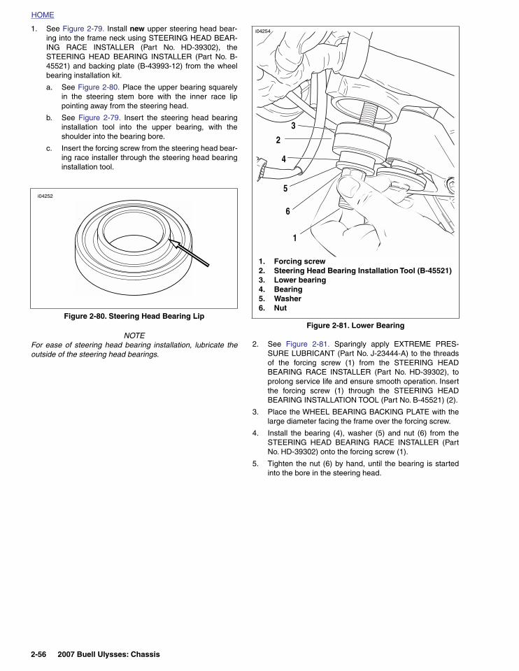
2. See Figure 2-81. Sparingly apply EXTREME PRES-SURE LUBRICANT (Part No. J-23444-A) to the threadsof the forcing screw (1) from the STEERING HEADBEARING RACE INSTALLER (Part No. HD-39302), toprolong service life and ensure smooth operation. Insertthe forcing screw (1) through the STEERING HEADBEARING INSTALLATION TOOL (Part No. B-45521) (2).
3. Place the WHEEL BEARING BACKING PLATE with thelarge diameter facing the frame over the forcing screw.
4. Install the bearing (4), washer (5) and nut (6) from theSTEERING HEAD BEARING RACE INSTALLER (PartNo. HD-39302) onto the forcing screw (1).
5. Tighten the nut (6) by hand, until the bearing is startedinto the bore in the steering head.
Figure 2-80. Steering Head Bearing Lip
i04252
Figure 2-81. Lower Bearing
i04254
1. Forcing screw2. Steering Head Bearing Installation Tool (B-45521)3. Lower bearing4. Bearing5. Washer6. Nut
6
5
4
3
2
1
2-56 2007 Buell Ulysses: Chassis

HOME
6. See Figure 2-82. Hold the forcing screw while tighteningthe nut to draw the bearing into the steering head. Con-tinue tightening until the bearing is fully seated.
7. Visually check to make sure the bearing is completelyseated against the shoulder in the steering head.
8. Repeat this process for the lower bearing.
9. Install forks, front wheel, and lower fork clamp/steeringstem as an assembly.
10. Install upper fork clamp.
11. Tighten steering stem capnut to 38-42 ft-lbs (52-57 Nm).
12. Use LOCTITE 271 (red) on steering stem pinch fastenerand tighten to 20-22 ft-lbs (27-29.8 Nm).
13. Apply LOCTITE 271 (red) to upper triple clamp fastenersand tighten to 23-25 ft-lbs (31-33.8 Nm).
14. Install headlight assembly and support bracket. See 2.28HEADLIGHTS AND SUPPORT BRACKET.
15. Install front brake lever housing. See 2.10 FRONTBRAKE MASTER CYLINDER AND HAND LEVER.
16. Install front modules. See 2.29 FRONT MODULES.
Figure 2-82. Install Bearings
i04255
Forcing screw
Nut
2007 Buell Ulysses: Chassis 2-57

HOME
SWINGARM AND BRACE 2.19
GENERAL
The swingarm also serves as the oil tank. For information onthe swingarm function as the oil tank, see 3.14 OILING SYS-TEM.
The swingarm features a removable brace on the right side toallow drive belt replacement.
REMOVAL
BraceNOTE
Before removing swingarm brace, always relieve belt tensionfirst. Removing swingarm brace without releasing tension willcause swingarm brace damage.
1. See Figure 2-83. Loosen rear axle pinch fastener (2).
2. Loosen rear axle (1) approximately 15 rotations to allowpartial tension to be removed from rear drive system.
3. Remove right side rider/passenger footpeg heel guardand mount with the rider and passenger footpegs. See2.34 HEEL GUARD AND FOOTPEG MOUNTS.
4. See Figure 2-85. Remove swingarm brace mounting fas-teners (10).
5. Remove swingarm brace (11).
Figure 2-83. Rear Wheel Mounting, Right Side
8420
2
1. Axle2. Pinch bolt fastener
1
Figure 2-84. Belt Guard Assembly
b1217x1x1. Fender/upper belt guard2. Fender/upper belt guard fasteners3. Lower stone guard4. Lower belt guard5. Lower belt guard fasteners6. Sprocket cover7. Lower stone guard fastener
4
1
4
3
5
2
67
7
2-58 2007 Buell Ulysses: Chassis
HOME
Swingarm1. Remove seat. See 2.45 SEAT.
11WARNING1WARNING
To prevent accidental vehicle start-up, which couldcause death or serious injury, disconnect battery cables(negative (-) cable first) before proceeding. (00307a)
2. Disconnect battery by unthreading fasteners removingnegative cable (black) from battery first. See 1.4 BAT-TERY MAINTENANCE.
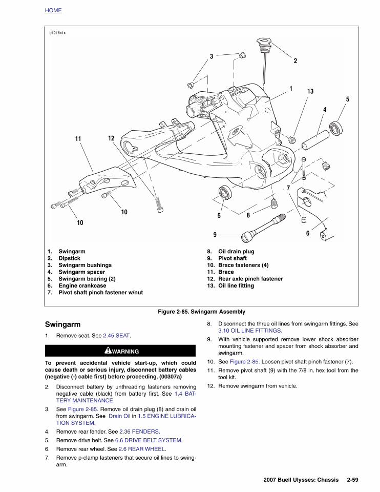
3. See Figure 2-85. Remove oil drain plug (8) and drain oilfrom swingarm. See Drain Oil in 1.5 ENGINE LUBRICA-TION SYSTEM.
4. Remove rear fender. See 2.36 FENDERS.
5. Remove drive belt. See 6.6 DRIVE BELT SYSTEM.
6. Remove rear wheel. See 2.6 REAR WHEEL.
7. Remove p-clamp fasteners that secure oil lines to swing-arm.
8. Disconnect the three oil lines from swingarm fittings. See3.10 OIL LINE FITTINGS.
9. With vehicle supported remove lower shock absorbermounting fastener and spacer from shock absorber andswingarm.
10. See Figure 2-85. Loosen pivot shaft pinch fastener (7).
11. Remove pivot shaft (9) with the 7/8 in. hex tool from thetool kit.
12. Remove swingarm from vehicle.
Figure 2-85. Swingarm Assembly
b1216x1x
1. Swingarm2. Dipstick3. Swingarm bushings4. Swingarm spacer5. Swingarm bearing (2)6. Engine crankcase7. Pivot shaft pinch fastener w/nut
8. Oil drain plug9. Pivot shaft10. Brace fasteners (4)11. Brace12. Rear axle pinch fastener13. Oil line fitting
2
4
5
1211
5
1
3
6
7
810
10
9
13
2007 Buell Ulysses: Chassis 2-59
HOME
DISASSEMBLY
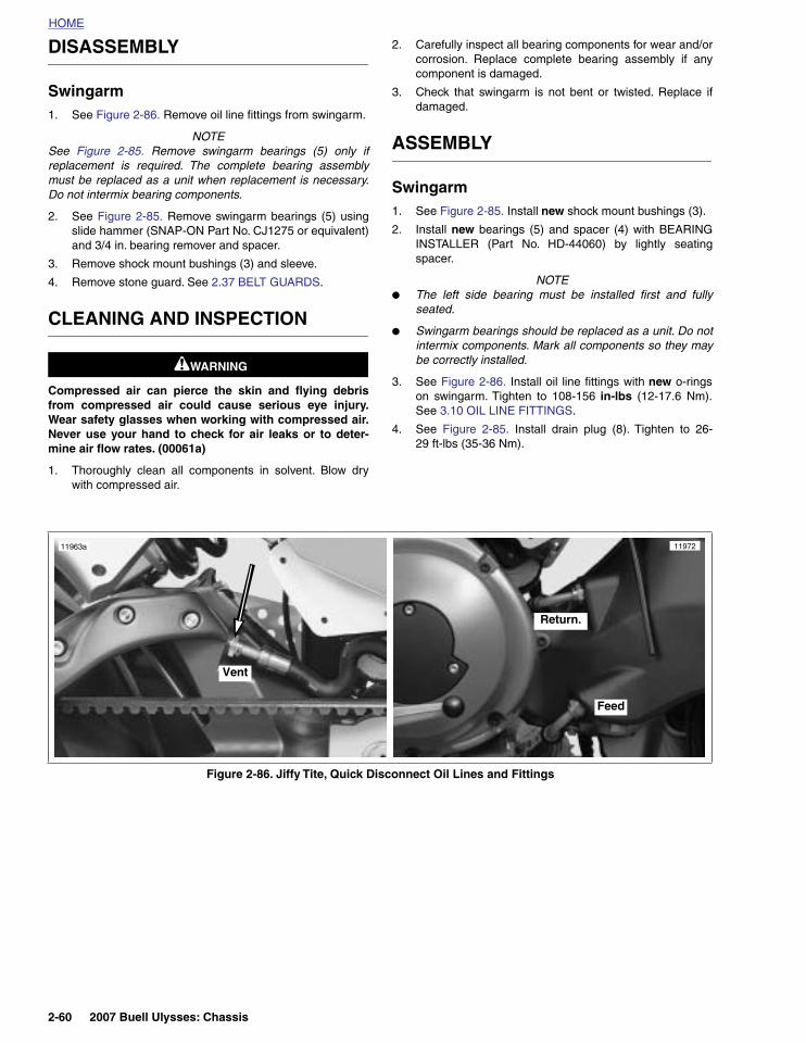
Swingarm1. See Figure 2-86. Remove oil line fittings from swingarm.
NOTESee Figure 2-85. Remove swingarm bearings (5) only ifreplacement is required. The complete bearing assemblymust be replaced as a unit when replacement is necessary.Do not intermix bearing components.
2. See Figure 2-85. Remove swingarm bearings (5) usingslide hammer (SNAP-ON Part No. CJ1275 or equivalent)and 3/4 in. bearing remover and spacer.
3. Remove shock mount bushings (3) and sleeve.
4. Remove stone guard. See 2.37 BELT GUARDS.
CLEANING AND INSPECTION
11WARNING1WARNING
Compressed air can pierce the skin and flying debrisfrom compressed air could cause serious eye injury.Wear safety glasses when working with compressed air.Never use your hand to check for air leaks or to deter-mine air flow rates. (00061a)
1. Thoroughly clean all components in solvent. Blow drywith compressed air.
2. Carefully inspect all bearing components for wear and/orcorrosion. Replace complete bearing assembly if anycomponent is damaged.
3. Check that swingarm is not bent or twisted. Replace ifdamaged.
ASSEMBLY
Swingarm1. See Figure 2-85. Install new shock mount bushings (3).
2. Install new bearings (5) and spacer (4) with BEARINGINSTALLER (Part No. HD-44060) by lightly seatingspacer.
NOTE ● The left side bearing must be installed first and fully
seated.
● Swingarm bearings should be replaced as a unit. Do notintermix components. Mark all components so they maybe correctly installed.
3. See Figure 2-86. Install oil line fittings with new o-ringson swingarm. Tighten to 108-156 in-lbs (12-17.6 Nm).See 3.10 OIL LINE FITTINGS.
4. See Figure 2-85. Install drain plug (8). Tighten to 26-29 ft-lbs (35-36 Nm).
Figure 2-86. Jiffy Tite, Quick Disconnect Oil Lines and Fittings
11963a
Vent
Feed
Return.
11972
2-60 2007 Buell Ulysses: Chassis

HOME
INSTALLATION
Swingarm1. See Figure 2-85. Align swingarm (1) in pivot of engine
crankcase (6).
2. Install pivot shaft (9) with the 7/8 in. hex tool from the toolkit. Apply ANTI-SEIZE and tighten to 24-26 ft-lbs (32-35 Nm).
3. Apply LOCTITE 271 (red), install and tighten pivot shaftpinch fastener (7) to 17-19 ft-lbs (23-26 Nm).
4. See Figure 2-93. Install shock bushings.
5. Install lower shock absorber mounting fastener andspacer from shock absorber and swingarm and tighten to15-17 ft-lbs (20.3-23 Nm).
6. Install right side footpeg mount. Tighten to 132-144 in-lbs (15-16.2 Nm). See 2.34 HEEL GUARD AND FOOT-PEG MOUNTS.
7. Connect the three oil lines to the swingarm fittings. See3.10 OIL LINE FITTINGS.
8. Install oil line p-clamps and tighten to 48-72 in-lbs (5.4-8Nm).
9. Install lower stone guard. See 2.37 BELT GUARDS.
10. Install rear wheel. See 2.6 REAR WHEEL.
NOTEInstalling the rear wheel will include installation of the beltdrive system. See 6.6 DRIVE BELT SYSTEM.
11. Install rear fender/belt guard. See 2.36 FENDERS.
12. Fill motorcycle with recommended oil. See 1.5 ENGINELUBRICATION SYSTEM.
Brace1. See Figure 2-85. Install swingarm brace (11) with swing-
arm brace mounting fasteners (10) loosely. Do nottighten.
2. Tighten swingarm brace fasteners (10) to 25-27 ft-lbs(34-37 Nm).
3. Tighten rear axle to 48-52 ft-lbs (65-70 Nm).
4. Tighten rear axle pinch fastener (12) to 40-45 ft-lbs (54-61 Nm).
5. Install right footpeg mount. Tighten to 132-144 in-lbs(15-16.2 Nm). See 2.34 HEEL GUARD AND FOOTPEGMOUNTS.
11WARNING1WARNING
Connect positive (+) battery cable first. If positive (+)cable should contact ground with negative (-) cable con-nected, the resulting sparks can cause a battery explo-sion, which could result in death or serious injury.(00068a)
6. Install battery by threading positive cable (red) intothreaded hole first tightening to 72-96 in-lbs (8-11 Nm).See 1.4 BATTERY MAINTENANCE.
11WARNING1WARNING
After installing seat, pull upward on front of seat to besure it is in locked position. While riding, a loose seat canshift causing loss of control, which could result in deathor serious injury. (00070a)
7. Install seat. See 2.45 SEAT.
Final Swingarm Inspection1. Check oil level after starting motorcycle and allowing it to
reach operating temperature.
2. Check rear brake operation.
11WARNING1WARNING
After servicing brakes and before moving motorcycle,pump brakes to build brake system pressure. Insufficientpressure can adversely affect brake performance, whichcould result in death or serious injury. (00279a)
2007 Buell Ulysses: Chassis 2-61

HOME
FRONT AND REAR ISOLATORS 2.20
FRONT ISOLATOR
RemovalNOTE
Avoid cross-threading front isolator bolt or insert. Keep weightof motorcycle off front isolator by alternately loosening frontisolator bolt and raising scissor jack to support engine.
1. Place a scissor jack under jacking point for supportingengine only. For location of jacking point see 2.32EXHAUST SYSTEM.
2. See Figure 2-87. Remove clutch cable wire form.
3. See Figure 2-88. Remove front isolator bolt (6).
4. Remove front isolator mount fasteners (5).
5. Remove front isolator bracket (4).
6. Remove upper snubber fastener (2) and remove uppersnubber (1).
Installation1. See Figure 2-88. If the threaded insert (3) is damaged
and needs to be replaced, install new insert with LOC-TITE 271 (red) and tighten to 59-61 ft-lbs (80-82.7 Nm).
2. Loosely install front isolator bracket (4) with front isolatorbolt (6).
3. See Figure 2-88. Install front isolator bracket fasteners(5), and tighten to 49-51 ft-lbs (66-69 Nm).
CAUTION
Avoid cross-threading front isolator bolt or insert. Keepweight of motorcycle off front isolator by alternatelytightening front isolator bolt and raising scissor jack tosupport engine.
4. Tighten front isolator bolt (6) to 49-51 ft-lbs (66-69 Nm).
NOTEHold wire form while tightening to prevent it from twisting.
5. See Figure 2-87. Install clutch cable wire form. Tightenfastener to 84-92 in-lbs (9.5-10.4 Nm).
NOTE
See Figure 2-88. If the threaded insert (3) is damaged andneeds to be replaced, install new insert with LOCTITE 271(red) and tighten to 59-61 ft-lbs (80-82.7 Nm).
REAR ISOLATOR
NOTEIt is necessary to remove engine to access rear isolator.
See 3.4 STRIPPING MOTORCYCLE FOR ENGINE SER-VICE to access the rear isolator.
Figure 2-87. Clutch Cable Wire Form
10500
Figure 2-88. Front Isolator
b1040x2x
1. Upper snubber2. Upper snubber fastener3. Insert4. Front isolator bracket5. Front isolator bracket fastener to engine (2)6. Front isolator bolt
1
2
3
4
6
5
2-62 2007 Buell Ulysses: Chassis

HOME
FRAME 2.21
REMOVAL
1. Remove fuel from frame. See DRAINING FUEL TANK in4.39 FUEL PUMP.
2. Rotate engine. See 3.3 ENGINE ROTATION FOR SER-VICE.
3. Remove exhaust header. See 2.32 EXHAUST SYSTEM.
4. Remove tail frame. See 2.41 LEFT TAIL SECTION ANDBATTERY PAN.
5. Remove rear shock. See 2.23 REAR SHOCKABSORBER.
6. Remove upper and lower fork clamps. See 2.17 FORKCLAMPS, UPPER AND LOWER.
7. Remove main wire harness. See 7.24 MAIN WIRE HAR-NESS.
8. Remove rear isolator fastener. See 3.4 STRIPPINGMOTORCYCLE FOR ENGINE SERVICE.
9. See Figure 2-89. Lift and remove frame from the motor-cycle.
INSTALLATION
1. Place frame over the motorcycle.
2. Install rear isolator fastener. See 3.5 ENGINE INSTAL-LATION.
3. Install main wire harness. See 7.24 MAIN WIRE HAR-NESS.
4. Install upper and lower fork clamps. See 2.17 FORKCLAMPS, UPPER AND LOWER.
5. Install rear shock. See 2.23 REAR SHOCK ABSORBER.
6. Install tail frame. See 2.41 LEFT TAIL SECTION ANDBATTERY PAN.
7. Install exhaust header. See 2.32 EXHAUST SYSTEM.
8. Rotate engine. See 3.3 ENGINE ROTATION FOR SER-VICE.
Figure 2-89. Lift Frame Off Motorcycle (Typical)
8483
2007 Buell Ulysses: Chassis 2-63
HOME
FRAME PUCKS 2.22
REMOVAL
11WARNING1WARNING
The aluminum frame of this motorcycle is the fuel tank.Drilling, welding, cutting, grinding, sanding, polishing orother modifications to this frame can weaken it or causea fire, which could result in death or serious injury.(00126b)
1. To break the adhesive bond, apply isopropyl alcoholalong the perimeter edge of the puck at the upper orlower rear corner. Wipe off excess alcohol.
2. Fit fingers under the corner edge and pry to loosen puck.
NOTEIf the puck fit prevents getting finger tips under puck, coverthe blade of a putty knife or similar tool with duct tape, to pre-vent scraping the frame, and pry up one corner of the puck.
3. Slip fingers under the loose corner and slowly pull thepuck away from the frame. Apply isopropyl alcohol asneeded to loosen remaining adhesive bond.
4. Clean adhesive from painted finish with isopropyl alco-hol. Wipe up excess alcohol with cloth.
INSTALLATION
1. Using isopropyl alcohol, clean the frame for the newpuck. Wait a minimum of 5 minutes for the alcohol toevaporate.
NOTEDo not sand or scuff the surface where the puck will beinstalled.
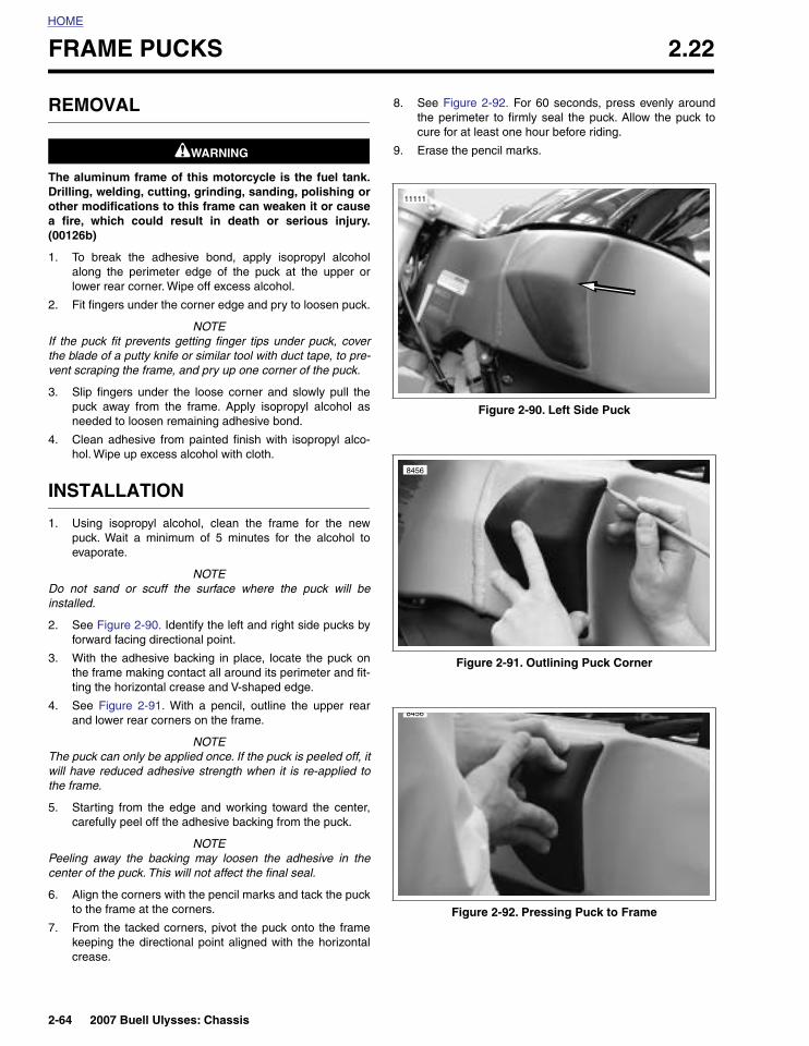
2. See Figure 2-90. Identify the left and right side pucks byforward facing directional point.
3. With the adhesive backing in place, locate the puck onthe frame making contact all around its perimeter and fit-ting the horizontal crease and V-shaped edge.
4. See Figure 2-91. With a pencil, outline the upper rearand lower rear corners on the frame.
NOTEThe puck can only be applied once. If the puck is peeled off, itwill have reduced adhesive strength when it is re-applied tothe frame.
5. Starting from the edge and working toward the center,carefully peel off the adhesive backing from the puck.
NOTEPeeling away the backing may loosen the adhesive in thecenter of the puck. This will not affect the final seal.
6. Align the corners with the pencil marks and tack the puckto the frame at the corners.
7. From the tacked corners, pivot the puck onto the framekeeping the directional point aligned with the horizontalcrease.
8. See Figure 2-92. For 60 seconds, press evenly aroundthe perimeter to firmly seal the puck. Allow the puck tocure for at least one hour before riding.
9. Erase the pencil marks.
Figure 2-90. Left Side Puck
Figure 2-91. Outlining Puck Corner
Figure 2-92. Pressing Puck to Frame
11111
8456
8456
2-64 2007 Buell Ulysses: Chassis
HOME
REAR SHOCK ABSORBER 2.23
GENERAL
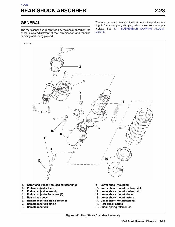
The rear suspension is controlled by the shock absorber. Theshock allows adjustment of rear compression and rebounddamping and spring preload.
The most important rear shock adjustment is the preload set-ting. Before making any damping adjustments, set the properpreload. See 1.11 SUSPENSION DAMPING ADJUST-MENTS.
Figure 2-93. Rear Shock Absorber Assembly
b1191x2x
7
8
5
1. Screw and washer, preload adjuster knob2. Preload adjuster knob3. Preload adjust assembly4. Preload adjuster fasteners (2)5. Rear shock body6. Remote reservoir clamp fastener7. Remote reservoir clamp8. Remote reservoir
9. Lower shock mount nut10. Lower shock mount washer, thick11. Lower shock mount washer, thin12. Lower shock mount sleeve13. Lower shock mount fastener14. Upper shock mount fastener15. Rear shock spring16. Shock spring retainer kit
1
2
3
6
12
14
16
15
9
13
11
4
10
2007 Buell Ulysses: Chassis 2-65

HOME
REMOVAL
1. Remove seat. See 2.45 SEAT.
11WARNING1WARNING
Disconnect negative (-) battery cable first. If positive (+)cable should contact ground with negative (-) cable con-nected, the resulting sparks can cause a battery explo-sion, which could result in death or serious injury.(00049a)
2. Disconnect and remove battery. See 1.4 BATTERYMAINTENANCE.
3. Place a scissor jack under jacking point at the rear muf-fler and raise chassis until load has been removed fromthe lower shock bolt (13). See 2.32 EXHAUST SYSTEMfor jacking point.
4. Cut and remove cable strap holding transmission ventline to shock assembly.
5. Cut and remove cable strap holding the remote preloadadjuster hose to main harness.
6. Remove ECM. See 4.30 ELECTRONIC CONTROLMODULE.
NOTEWhen removing the ECM, the fastener closest to the shockassembly has a nut that is captured in the plastic shield belowthe ECM. You need to place your finger under the nut whenremoving the fastener to prevent the nut from falling out. Slidethe ECM to one side and loosely install the fastener to retainthe nut in the correct location. The rear fastener attachesdirectly to the battery pan.
7. See Figure 2-93. Remove reservoir retainer fastener (6)and retainer (7).
8. Remove the two fasteners (4) holding the preloadadjuster in place.
9. Remove the nut (9) and thick washer (10) from the lowershock bolt and raise scissor jack until the lower bolt canbe removed by hand.
10. After removing both shock fasteners (13, 14), removerear shock assembly.
NOTES● Remove shock assembly through the top of the tail sec-
tion (opening beneath rider seat).
● If preload knob is removed for any reason, there is aspring and check ball that is held in place by the knob.Use caution when removing knob in order to not losespring and check ball.
● If it is necessary to remove the preload adjuster knobfastener, when reinstalling the fastener, tighten to 25-43in-lbs (2.8-4.9 Nm).
INSTALLATION
1. See Figure 2-93. Lower rear shock assembly, preloadadjuster assembly and remote reservoir into position.
NOTERear brake switch wiring is routed over the remote reservoir.
2. Install fastener (14) and tighten to 48-52 ft-lbs (65-70.5 Nm).
3. Install lower shock mount with fasteners (9, 10,11, and13) and lower shock mount sleeve (12) and tighten to 15-17 ft-lbs (20.3-23 Nm).
NOTE● See Figure 2-94. Verify preload adjuster knob is facing
out.
● Verify that fan spins freely after shock is installed.
4. Install the two fasteners holding the preload adjuster inplace and tighten to 36-60 in-lbs (4.0-6.7 Nm).
5. Install rear shock reservoir clamp (7) and fastener (6)and tighten clamp fastener to 80-88 in-lbs (9.0-9.9 Nm).
6. Install ECM. See 4.30 ELECTRONIC CONTROL MOD-ULE.
7. Install cable strap securing preload adjuster hose tomain harness.
8. Install cable strap securing transmission vent line toshock assembly.
9. Lower scissor jack and remove from under vehicle.
11WARNING1WARNING
Connect positive (+) battery cable first. If positive (+)cable should contact ground with negative (-) cable con-nected, the resulting sparks can cause a battery explo-sion, which could result in death or serious injury.(00068a)
10. Install positive battery cable (red) to positive terminal ofbattery. Tighten to 72-96 in-lbs (8-11 Nm).
11. Connect negative battery cable. Tighten to 72-96 in-lbs(8-11 Nm).
11WARNING1WARNING
After installing seat, pull upward on front of seat to besure it is in locked position. While riding, a loose seat canshift causing loss of control, which could result in deathor serious injury. (00070a)
12. Install seat. See 2.45 SEAT.
Figure 2-94. Rear Shock Absorber Preload Adjuster Knob
11958
2-66 2007 Buell Ulysses: Chassis
HOME
THROTTLE CONTROL 2.24
REMOVAL/DISASSEMBLY
1. Remove right handlebar deflector. See 2.25 DEFLEC-TORS/HANDLEBARS.
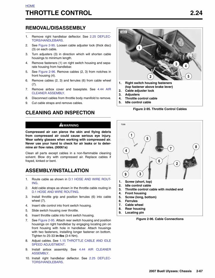
2. See Figure 2-95. Loosen cable adjuster lock (thick disc)(3) on each cable.
3. Turn adjusters (3) in direction which will shorten cablehousings to minimum length.
4. Remove fasteners (1) on right switch housing and sepa-rate housing from handlebar.
5. See Figure 2-96. Remove cables (2, 3) from notches infront housing (4).
6. Remove cables (2, 3) and ferrules (6) from cable wheel(7).
7. Remove airbox cover and baseplate. See 4.44 AIRCLEANER ASSEMBLY.
8. Disconnect cables from throttle body manifold to remove.
9. Cut cable straps and remove cables.
CLEANING AND INSPECTION
11WARNING1WARNING
Compressed air can pierce the skin and flying debrisfrom compressed air could cause serious eye injury.Wear safety glasses when working with compressed air.Never use your hand to check for air leaks or to deter-mine air flow rates. (00061a)
Clean all parts except cables in a non-flammable cleaningsolvent. Blow dry with compressed air. Replace cables iffrayed, kinked or bent.
ASSEMBLY/INSTALLATION
1. Route cable as shown in D.1 HOSE AND WIRE ROUT-ING.
2. Add cable straps as shown in the throttle cable routing inD.1 HOSE AND WIRE ROUTING.
3. Install throttle grip and position ferrules (6) into cablewheel (7).
4. Insert idle control into front switch housing.
5. Slide switch housing over throttle.
6. Insert throttle cable into front switch housing.
7. See Figure 2-95. Attach rear switch housing and positionhousings on right handlebar by engaging locating pin onfront housing with hole in handlebar. Attach housingswith two fasteners, installing longer fastener on bottom.Tighten to 25-33 in-lbs (3-4 Nm).
8. Adjust cables. See 1.15 THROTTLE CABLE AND IDLESPEED ADJUSTMENT.
9. Install airbox assembly. See 4.44 AIR CLEANERASSEMBLY.
10. Install right handlebar deflector. See 2.25 DEFLEC-TORS/HANDLEBARS.
Figure 2-95. Throttle Control Cables
Figure 2-96. Cable Connections
1. Right switch housing fasteners (top fastener above brake lever)
2. Cable adjuster lock3. Adjusters4. Throttle control cable5. Idle control cable
6853
2
1
3
5
4
1. Screw (short, top)2. Idle control cable3. Throttle control cable with molded end4. Front housing5. Screw (long, bottom)6. Ferrules7. Cable wheel8. Rear housing9. Locating pin
1
7098
487
5
3
26
9
2007 Buell Ulysses: Chassis 2-67

HOME
DEFLECTORS/HANDLEBARS 2.25
REMOVAL/DISASSEMBLY
1. Remove fasteners (2) from clutch and brake pivot shafts(3 & 6) and pivot shaft risers (4).
2. Unsnap deflectors (1) from handlebar endcaps (7).
3. Lift deflectors off of the pivot shafts (3 & 6) and pivotshaft risers (4).
4. Loosen pivot shaft riser (4) and jam nut (5) and removefrom both pivot shafts (3 & 6).
5. Remove pivot shafts (3 & 6) with levers.
ASSEMBLY/INSTALLATION
1. Install brake and clutch levers with pivot shafts (3 & 6).See 2.26 CLUTCH CONTROL/CABLE and 2.10 FRONTBRAKE MASTER CYLINDER AND HAND LEVER forprocedure details.
2. Install jam nuts (5) and tighten to 39-48 in-lbs (4.4-5.4Nm).
3. Install pivot shaft risers (4) and tighten to 43-49 in-lbs(4.8-5.5 Nm).
4. Spread deflectors (1) and place over the pivot shaft andriser ends.
5. Snap deflectors onto handlebar end caps (7).
6. Install new deflector fasteners (2) and tighten to 24-36in-lbs (2.7-4.1 Nm).
Figure 2-97. Deflectors
2
2
2
1. Deflectors2. Deflector fasteners (4)3. Clutch pivot shaft4. Pivot shaft riser5. Pivot shaft jam nut6. Brake pivot shaft7. Handlebar end cap
7
1
1
3
6 4
b1170x2x
4
5
5
2
2-68 2007 Buell Ulysses: Chassis

HOME
CLUTCH CONTROL/CABLE 2.26
GENERAL
For clutch adjustment, see 1.8 CLUTCH.
For clutch replacement, see 6.4 CLUTCH.
REMOVAL/DISASSEMBLY
Clutch Cable
11WARNING1WARNING
To prevent accidental vehicle start-up, which couldcause death or serious injury, disconnect negative (-)battery cable before proceeding. (00048a)
1. Remove seat. See 2.45 SEAT.
2. Disconnect negative battery cable. See 1.4 BATTERYMAINTENANCE.
3. Remove chin fairing. See 2.38 CHIN FAIRING.
4. Cut tie wrap from clutch cable/regulator wire harness.
NOTEAlways disconnect front tie bar from the "V" bracket first.
5. Remove front tie bar from “V” bracket.
6. Remove front tie bar, P-clamp (2) and clutch cable fromengine.
7. See Figure 2-98. Slide clutch cable adjuster boot (1) upto access clutch adjuster (2).
8. Loosen clutch adjuster (2) to release tension from handlever and clutch release mechanism.
9. See Figure 2-100. Remove clutch cable ferrule (7) fromhand lever (4).
NOTESee D.1 HOSE AND WIRE ROUTING in Appendix D.
10. Pull clutch cable down and out of upper triple clamp.
11. Remove three TORX screws with washers securingclutch inspection cover.
Figure 2-98. Clutch Cable Adjuster Mechanism
x0055x6x
1. Rubber boot2. Cable adjuster3. Jam nut4. Cable end
12
3
4
Figure 2-99. Clutch Cable Wire Form
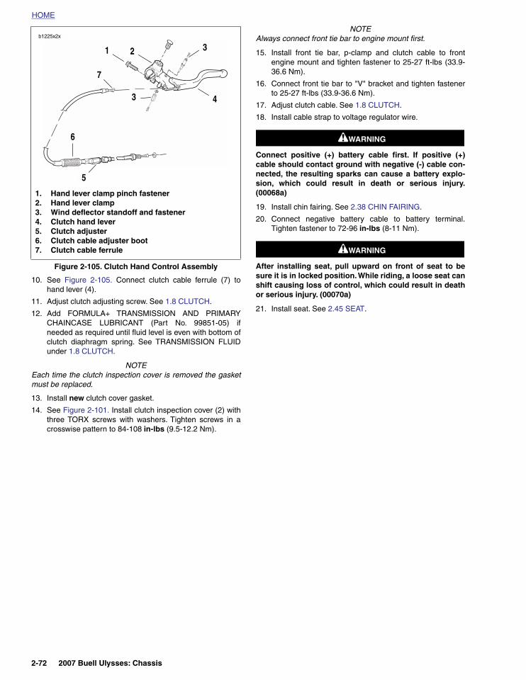
Figure 2-100. Clutch Hand Control Assembly
12126
2
1. Clutch cable wire form2. P-clamp
1
1. Hand lever clamp pinch fastener2. Hand lever clamp3. Wind deflector standoff4. Clutch hand lever5. Clutch adjuster6. Clutch cable adjuster boot7. Clutch cable ferrule
b1225x2x
31
7
43
5
2
6
2007 Buell Ulysses: Chassis 2-69

HOME
12. See Figure 2-101. Remove clutch inspection cover (2).
13. Remove complete shift assembly.
a. Remove flange bolt (6) from primary cover.
b. Remove engine shift lever assembly (3). Do notscratch primary cover.
14. See Figure 2-102. Remove the outer ramp and hook (1)from the cable end (3) and coupling (2). Remove cable
end from slot in coupling. See 6.3 CLUTCH RELEASEMECHANISM.
15. See Figure 2-103. Unscrew the cable fitting from the pri-mary cover. Remove clutch cable and fitting.
16. Remove and discard o-ring on the clutch cable fitting.
Figure 2-101. Shifter Linkage
1. Primary cover2. Clutch inspection cover3. Engine shift lever4. Shift pedal assembly5. Shift linkage assembly
6. Flange head bolt7. Shifter bracket8. Drain plug9. Sleeve, shift lever10. Bearings, shift lever
1
5
6
7
b1194x2x
24
3
8
9
10
10
Figure 2-102. Clutch Release Mechanism (Typical)
1. Outer ramp and hook2. Coupling3. Cable end
1
23
8413
Figure 2-103. Clutch Cable and Fitting
11168
2-70 2007 Buell Ulysses: Chassis

HOME
ASSEMBLY/INSTALLATION
Clutch Cable1. Install new O-ring on the clutch cable fitting before
installing.
2. Apply 565 thread sealer to fitting on clutch cable andscrew the clutch cable fitting into the primary cover andtighten to 36-108 in-lbs (4-12.2 Nm).
3. See Figure 2-102. Install cable end into slot in coupling.Install the outer ramp and hook (1) onto the cable end (3)and coupling (2) and place assembly back into the clutchinspection area in the primary cover. See 6.3 CLUTCHRELEASE MECHANISM.
4. See Figure 2-104. Install rubber washer and shift leverassembly (1).
5. See Figure 2-101. Install (10) bearings and (9) sleeveinto the shift lever.
6. After applying LOCTITE 271 (red), install flange bolt (5)and shift pedal to primary cover, and tighten to 22-24 ft-lbs (30-32.5Nm).
7. After applying LOCTITE 271 (red), tighten engine shiftlever pinch screw to 48-60 in-lbs (5.4-6.8 Nm).
8. See Figure 2-104. If the shift linkage assembly (8) wasremoved for any reason, apply Loctite 271 to fastenersand tighten to 36-60 in-lbs (4-6.8 Nm). Adjust to ridercomfort.
NOTE
See D.1 HOSE AND WIRE ROUTING in Appendix D.
9. Route clutch cable through clutch cable wire form andupper triple clamp.
Figure 2-104. Installing Shift Linkage
1. Lever, engine2. Primary cover3. Clutch inspection cover4. Drain plug5. Flange head bolt6. Chain adjuster screw7. Locknut8. Shift linkage assembly
3
2
4
7
1
12032
8
6
5
2007 Buell Ulysses: Chassis 2-71
HOME
10. See Figure 2-105. Connect clutch cable ferrule (7) tohand lever (4).
11. Adjust clutch adjusting screw. See 1.8 CLUTCH.
12. Add FORMULA+ TRANSMISSION AND PRIMARYCHAINCASE LUBRICANT (Part No. 99851-05) ifneeded as required until fluid level is even with bottom ofclutch diaphragm spring. See TRANSMISSION FLUIDunder 1.8 CLUTCH.
NOTEEach time the clutch inspection cover is removed the gasketmust be replaced.
13. Install new clutch cover gasket.
14. See Figure 2-101. Install clutch inspection cover (2) withthree TORX screws with washers. Tighten screws in acrosswise pattern to 84-108 in-lbs (9.5-12.2 Nm).
NOTEAlways connect front tie bar to engine mount first.
15. Install front tie bar, p-clamp and clutch cable to frontengine mount and tighten fastener to 25-27 ft-lbs (33.9-36.6 Nm).
16. Connect front tie bar to "V" bracket and tighten fastenerto 25-27 ft-lbs (33.9-36.6 Nm).
17. Adjust clutch cable. See 1.8 CLUTCH.
18. Install cable strap to voltage regulator wire.
11WARNING1WARNING
Connect positive (+) battery cable first. If positive (+)cable should contact ground with negative (-) cable con-nected, the resulting sparks can cause a battery explo-sion, which could result in death or serious injury.(00068a)
19. Install chin fairing. See 2.38 CHIN FAIRING.
20. Connect negative battery cable to battery terminal.Tighten fastener to 72-96 in-lbs (8-11 Nm).
11WARNING1WARNING
After installing seat, pull upward on front of seat to besure it is in locked position. While riding, a loose seat canshift causing loss of control, which could result in deathor serious injury. (00070a)
21. Install seat. See 2.45 SEAT.
Figure 2-105. Clutch Hand Control Assembly
1. Hand lever clamp pinch fastener2. Hand lever clamp3. Wind deflector standoff and fastener4. Clutch hand lever5. Clutch adjuster6. Clutch cable adjuster boot7. Clutch cable ferrule
b1225x2x
31
7
43
5
2
6
2-72 2007 Buell Ulysses: Chassis

HOME
HEADLIGHT GRILLE 2.27
REPLACEMENT
1. See Figure 2-106. Grab headlight grille on both sidesand spread to remove grill.
NOTEWhen spreading the headlight grille during removal/installa-tion be careful not to spread the grille too far. If this happenssimply bend the grille back until it fits snugly on the head-lights.
2. Spread headlight grille with hands and snap it back inplace over the headlights.
Figure 2-106. Headlight Grille
12051
2007 Buell Ulysses: Chassis 2-73

HOME
HEADLIGHTS AND SUPPORT BRACKET 2.28
REMOVAL
1. Remove seat. See 2.45 SEAT.
11WARNING1WARNING
To prevent accidental vehicle start-up, which couldcause death or serious injury, disconnect negative (-)battery cable before proceeding. (00048a)
2. Disconnect negative (–) cable (black) from battery. See1.4 BATTERY MAINTENANCE.
3. Remove windshield and windscreen. See 2.44 WIND-SHIELD AND WINDSCREEN.
4. See Figure 2-107. Disconnect horn connectors [122] (2).
NOTEHorn (1) can remain attached to support bracket. The horncan be removed and replaced as needed.
5. See Figure 2-107. Separate headlight connector [38] (5).
6. Remove female connector [38B] from support bracket (9)by sliding connector up and off of bracket clip.
7. Remove both upper headlight fasteners (6).
NOTEAccess the headlight fasteners with a socket extensionthrough the openings in the sides of the front modules.
8. Remove headlight alignment fastener from underside offront fender and remove headlights.
9. Remove two fasteners (8) from in the left and right mod-ules and remove support bracket.
Figure 2-107. Headlight and Support Bracket
1. Horn2. Horn connectors [122]3. Horn bracket4. Horn fastener5. Headlight connector [38]
6. Screws (2), upper headlight mounting7. Headlight assembly8. Screws (2), headlight support bracket9. Headlight support bracket10. Left and right front modules
11930a
7
1
3
5
8
9
10
2
4
8
766
10
2-74 2007 Buell Ulysses: Chassis

HOME
DISASSEMBLY
1. See Figure 2-108. Remove rubber boots (1) from rear ofheadlight housing.
2. Disconnect wiring harness (5) from headlight bulbs (3)and remove along with position bulb socket (6).
3. Remove bulb holders (2).
4. Remove headlight bulbs (3) from back of headlight hous-ing (4).
ASSEMBLY
1. See Figure 2-108. Align and install headlight bulbs (3)into back of headlight housing (4).
NOTEThe tab on the base of the headlight bulb should restbetween the two tabs located at the top of the hole on theback of the headlight assembly.
2. Install bulb holders (2).
3. Connect wiring harness (5) to headlight bulbs (3) andinstall rubber boots (1) and install position bulb socket (6)between the headlights. For alignment of rubber boots,see 7.12 HEADLIGHT.
Figure 2-108. Headlight Assembly
1. Boot (2)2. Bulb holder (2)3. Bulb (2)4. Headlight housing5. Wiring harness6. Position bulb socket
(used for HDI only)7. Headlight connector
b1226x2x
12
3
4
5
6
b1150x2x
7
2007 Buell Ulysses: Chassis 2-75

HOME
INSTALLATION
1. See Figure 2-109. Install headlight support bracket (9).
2. Apply LOCTITE 271 (red) and install fasteners (8) secur-ing headlight support bracket/turn signal flasher to leftand right front modules (10) and tighten to 48-72 in-lbs(5.4-8.1 Nm).
3. Install headlight assembly.
a. Install headlight assembly (7) into headlight supportbracket (9).
b. Install both upper headlight fasteners (6) but do nottighten.
c. Install lower fastener (under the front fender), do nottighten.
4. Attach headlight connector to headlight support bracket.
5. Connect headlight connector [38] (5).
6. Install horn (1) and tighten fastener (4) to 36-60 in-lbs(4-6.7 Nm).
7. Connect horn connectors [122] (2).
8. Adjust headlights. See 1.18 HEADLIGHTS.
9. Install windshield and windscreen. See 2.44 WIND-SHIELD AND WINDSCREEN.
11WARNING1WARNING
Connect positive (+) battery cable first. If positive (+)cable should contact ground with negative (-) cable con-nected, the resulting sparks can cause a battery explo-sion, which could result in death or serious injury.(00068a)
10. Install battery by threading positive cable (red) intothreaded hole first tightening to 72-96 in-lbs (8-11 Nm).See 1.4 BATTERY MAINTENANCE.
11WARNING1WARNING
After installing seat, pull upward on front of seat to besure it is in locked position. While riding, a loose seat canshift causing loss of control, which could result in deathor serious injury. (00070a)
11. Install seat. See 2.45 SEAT.
Figure 2-109. Headlight and Support Bracket
1. Horn2. Horn connectors [122]3. Horn bracket4. Horn fastener5. Headlight connector [38]
6. Screws (2), upper headlight mounting7. Headlight assembly8. Screws (2), headlight support bracket9. Headlight support bracket10. Left and right front modules
11930a
7
1
3
5
8
9
10
2
4
8
766
10
2-76 2007 Buell Ulysses: Chassis

HOME
FRONT MODULES 2.29
REMOVAL
1. Remove seat. See 2.45 SEAT.
11WARNING1WARNING
To protect against accidental start-up of vehicle and pos-sible personal injury, disconnect the negative batterycable before proceeding. Inadequate safety precautionscould cause a battery explosion, which could result indeath or serious injury.
2. Disconnect battery by unthreading fastener removingnegative cable (black) from battery first. See 1.4 BAT-TERY MAINTENANCE.
3. Remove windshield and windscreen. See 2.44 WIND-SHIELD AND WINDSCREEN.
4. Remove headlight assembly and support bracket. See2.28 HEADLIGHTS AND SUPPORT BRACKET.
5. Disconnect and remove instrument module and auxiliarypower outlet connectors.
6. See Figure 2-111. Remove upper module (5) fastenersand remove upper module.
7. Remove ignition switch. See 7.3 IGNITION/HEADLIGHTKEY SWITCH.
NOTESee Figure 2-110. Once the ignition switch has beenremoved there will be two remaining fasteners.
8. Disconnect front turn signals. See 7.15 TURN SIGNALS.
9. See Figure 2-110. Remove fastener attaching p-clamp torear side of right front module.
NOTESee Figure 2-111. Once the clamp load has been releasedon the final fastener securing the right front module to theupper triple clamp, the left front module can be removed.
10. See Figure 2-110. Loosen but do not remove final fas-tener securing the right front module to upper tripleclamp.
11. See Figure 2-111. Remove the left front module.
12. See Figure 2-110. Remove the final fastener and theright front module.
INSTALLATION
1. See Figure 2-110. Install right front module leaving sin-gle fastener loose.
2. After installing the left front module and aligning withholes in upper triple clamp, tighten previously installedsingle fastener to 12-14 ft-lbs (16.3-19 Nm).
3. Attach front brake line p-clamp to rear of right front mod-ule and tighten fastener to 36-60 in-lbs (4.1-6.8 Nm).
4. Install ignition switch. See 7.3 IGNITION/HEADLIGHTKEY SWITCH.
5. Install and connect instrument module. See 7.19INSTRUMENT MODULE.
6. Connect turn signals. See 7.15 TURN SIGNALS.
7. See Figure 2-111. Install upper module (5). Tighten fas-teners to 36-60 in-lbs (4.1-6.8 Nm).
8. Connect speedometer and auxiliary outlet.
9. Install headlight assembly and support bracket. 2.28HEADLIGHTS AND SUPPORT BRACKET.
10. Install windshield and windscreen. See 2.44 WIND-SHIELD AND WINDSCREEN.
11WARNING1WARNING
Always connect the positive battery cable first. If the pos-itive cable should contact ground with the negative cableinstalled, the resulting sparks may cause a battery explo-sion which could result in death or serious injury.
11. Install battery by threading positive cable (red) intothreaded hole first tightening to 72-96 in-lbs (8-11 Nm).See 1.4 BATTERY MAINTENANCE.
11WARNING1WARNING
After installing seat, pull upward on front of seat to besure it is in locked position. While riding, a loose seat canshift causing loss of control, which could result in deathor serious injury. (00070a)
12. Install seat. See 2.45 SEAT.
2007 Buell Ulysses: Chassis 2-77

HOME
Figure 2-110. Right Front Module Fastener and Brake Line P-Clamp Fastener (Typical)
8998
Figure 2-111. Front Module
b1193x2x
1. Left and right front module2. Right front module overlaps left front module3. Right front module4. Left front module5. Upper module
2
3
4
b1192x2x
51
2-78 2007 Buell Ulysses: Chassis

HOME
HANDLEBARS 2.30
REMOVAL
1. Remove seat. See 2.45 SEAT.
11WARNING1WARNING
To prevent accidental vehicle start-up, which couldcause death or serious injury, disconnect negative (-)battery cable before proceeding. (00048a)
2. Disconnect battery negative cable.
3. Remove deflectors. See 2.25 DEFLECTORS/HANDLE-BARS.
4. Remove left handlebar switch housing. See 7.17 HAN-DLEBAR SWITCHES. Cut left handlebar grip andremove.
5. Detach clutch hand control from handlebars. See 2.26CLUTCH CONTROL/CABLE.
6. Remove front brake master cylinder. See 2.10 FRONTBRAKE MASTER CYLINDER AND HAND LEVER.
7. Loosen screws on right handlebar switch housing, but donot detach throttle grip assembly from handlebar. See2.24 THROTTLE CONTROL.
8. Remove four harness retainers securing switch housingharnesses to handlebars.
9. See Figure 2-112. Remove the four screws holdingupper handlebar clamp.
NOTERight hand control assembly may now be removed fromdetached handlebar.
10. Remove handlebars without stretching throttle cables.
11. See Figure 2-112. Remove endcaps.
INSTALLATION
1. Slide handlebars into throttle grip assembly. Fasten righthandlebar switch housing to handlebar. See 2.24THROTTLE CONTROL.
2. See Figure 2-112. Attach handlebars.
a. Position handlebar on lower clamp.
b. Place the upper handlebar clamp in position andthread the four screws in place after applying LOC-TITE 271 (red).
c. Tighten both front screws to 10-12 ft-lbs (14-16 Nm).
d. Then tighten both rear screws (2) 10-12 ft-lbs (14-16Nm).
3. Install clutch hand control. Tighten but do not torque. See2.26 CLUTCH CONTROL/CABLE.
4. Install left switch housing. See 7.17 HANDLEBARSWITCHES.
5. Check control wire routing. See D.1 HOSE AND WIREROUTING.
a. Route right hand control wires between the lowerclamp and fork tube and on the outside of the clutchcable.
b. Route left hand control wires between the lowerclamp and fork tube.
c. Install harness retainers.
6. Install a new left hand grip.
7. Position clutch hand lever to rider preferences andtighten fastener (1) to 60-84 in-lbs (6.8-9.5 Nm). See2.26 CLUTCH CONTROL/CABLE.
8. Install front brake master cylinder. See 2.10 FRONTBRAKE MASTER CYLINDER AND HAND LEVER.
9. Install deflectors. See 2.25 DEFLECTORS/HANDLE-BARS.
10. Check steering motion range to both fork stops.
11WARNING1WARNING
Connect positive (+) battery cable first. If positive (+)cable should contact ground with negative (-) cable con-nected, the resulting sparks can cause a battery explo-sion, which could result in death or serious injury.(00068a)
11. Install battery by threading positive cable (red) intothreaded hole first tightening to 72-96 in-lbs (8-11 Nm).See 1.4 BATTERY MAINTENANCE.
11WARNING1WARNING
After installing seat, pull upward on front of seat to besure it is in locked position. While riding, a loose seat canshift causing loss of control, which could result in deathor serious injury. (00070a)
12. Install seat. See 2.45 SEAT.
2007 Buell Ulysses: Chassis 2-79

HOME
Figure 2-112. Handlebar Assembly
b1209x1x
1. Endcap (2)2. Handlebar3. Handlebar clamp4. Clamp fasteners (4)5. Left hand grip6. Harness retainer (4)
1
5
2
3
4
1
6
2-80 2007 Buell Ulysses: Chassis

HOME
MIRRORS 2.31
REMOVAL
1. See Figure 2-113. Loosen adjuster nut (2) and removemirror (1) from mount (3).
2. Loosen mount (3) and remove from bracket (4).
INSTALLATION
1. Install mount (3) onto bracket (4) and tighten to 20-22 ft-lbs (27.1-29.8 Nm).
NOTEBefore tightening adjuster nut, position mirrors for rider.
2. Install mirror (1) and tighten adjuster to 115-130 in-lbs(13-14.7 Nm).
Figure 2-113. Mirrors and Mounting Hardware
1. Mirror2. Adjuster nut3. Mount4. Bracket
1
1
2
3
2
3
4
12066
b1210x1x
2007 Buell Ulysses: Chassis 2-81
HOME
EXHAUST SYSTEM 2.32
REMOVAL/DISASSEMBLY
NOTEFor details on removal of interactive exhaust system compo-nents, see REMOVAL under 7.6 INTERACTIVE EXHAUSTSYSTEM.
Muffler1. Remove chin fairing. See 2.38 CHIN FAIRING.
2. Remove front sprocket cover. See 2.35 SPROCKETCOVER.
3. Remove idler pulley. See DRIVE BELT REMOVAL in 1.9DRIVE BELT.
4. See Figure 2-114. Loosen front muffler mount fastener(5) but do not remove.
5. Remove front and rear muffler straps.
Front: Remove front muffler strap fastener (4).
NOTEAlways replace the front muffler strap.
Rear: Alternately loosen rear strap fasteners (7) andremove straps (8).
6. See Figure 2-115. Loosen Torca clamp (1).
7. Disconnect interactive exhaust cable and remove muffler.
NOTEThe muffler may be removed for replacement without remov-ing the exhaust header.
Front Muffler Mount1. Remove muffler.
NOTEFor details on removal of interactive exhaust system compo-nents, see REMOVAL under 7.6 INTERACTIVE EXHAUSTSYSTEM.
2. See Figure 2-114. Remove front muffler mount fastener(5).
3. Remove strap (3) from front muffler mount (5).
4. Remove front muffler mount bushings by punching outwith suitable tool.
Rear Muffler Bracket1. Remove muffler.
2. Drain oil. See Drain Oil in 1.5 ENGINE LUBRICATIONSYSTEM.
3. Remove oil feed line and p-clamp from swingarm. See3.9 OIL HOSE ROUTING AND OIL RESERVOIR.
4. See Figure 2-114. Remove rear muffler bracket fasten-ers.
5. Slide oil lines from rear muffler bracket off the oil feedline and remove rear muffler bracket.
Exhaust Header1. Rotate engine down. See 3.3 ENGINE ROTATION FOR
SERVICE.
2. Remove oxygen sensor. See 4.33 OXYGEN SENSOR.
3. See Figure 2-115. Remove exhaust header (2) byremoving mounting fasteners (3).
4. Remove exhaust ring (4), retaining ring (5) and port gas-ket (6).
2-82 2007 Buell Ulysses: Chassis

HOME
ASSEMBLY/INSTALLATION
Exhaust Header1. See Figure 2-115. Install exhaust ring (4), retaining ring
(5) and new port gasket (6).
2. Install exhaust header (2). Tighten mounting fasteners(3) to 72-96 in-lbs (8-11 Nm).
NOTES● The front header fasteners must be torqued first.
● Tighten header nuts gradually, alternating between studsto insure that exhaust rings are flush with engine.
3. Install oxygen sensor. See 4.33 OXYGEN SENSOR.
4. Rotate engine up. See 3.3 ENGINE ROTATION FORSERVICE.
Rear Muffler Bracket1. See Figure 2-114. Slide rear muffler bracket over oil feed
line.
2. Apply LOCTITE 271 (red), install rear muffler bracket fas-teners and tighten to 32-36 ft-lbs (43-49 Nm).
3. Install oil feed line and p-clamp. Tighten p-clamp to 48-72in-lbs (5.4-8 Nm). See 3.9 OIL HOSE ROUTING ANDOIL RESERVOIR.
4. Fill swingarm/oil tank with 2.5 quarts (3.3 liters) oil. SeeDrain Oil in 1.5 ENGINE LUBRICATION SYSTEM.
5. Install muffler.
Front Muffler Mount1. See Figure 2-114. Install front muffler mount bushings.
2. Install new strap on front muffler mount (5).
3. Install front fastener loosely. Do not tighten.
4. Install muffler.
NOTEFor assembly details of the interactive exhaust system, seeINSTALLATION under 7.6 INTERACTIVE EXHAUST SYS-TEM.
Figure 2-114. Muffler and Mounting System
b0986x3c
1. Clamp, Torca2. Muffler3. Muffler strap, front4. Front muffler strap fastener5. Front muffler mount6. Rear muffler bracket7. Rear muffler strap fastener8. Muffler strap, rear (2)9. Jacking point symbol10. Symbol location
4
6
5
23
7
8
1
9
10
10
2007 Buell Ulysses: Chassis 2-83

HOME
Muffler and StrapsNOTE
Torca muffler clamps have eliminated the need for silicone orgraphite tape during assembly. To ensure sealing integrity ofmuffler clamps and prevent the possibility of leakage, Buellrecommends that muffler clamp assemblies be discarded andreplaced each time they are removed.
1. Install muffler and new Torca clamp onto header.
NOTEIf necessary, use a fiber hammer to fit muffler on header.
2. Install interactive exhaust cable to muffler.
3. See Figure 2-114. Loosely install new front and rearmuffler straps (2, 4).
NOTES● Never re-use front muffler strap. Always replace front
muffler strap with a new strap when removed from sys-tem.
● It is important that the front muffler mount is tightenedlast in order to ensure proper alignment of the exhaustsystem.
● When rear muffler straps have been installed, it is impor-tant that strap fasteners do not contact idler pulleybracket.
● On the front muffler mount fastener, torque is applied tothe head and not to the nut.
4. Tighten front strap fastener and alternately tighten rearmuffler strap fasteners evenly till fasteners are tightenedto:
a. Front: Tighten around the muffler until snug.
b. Rear: 48-60 in-lbs (5-7 Nm).
c. Front muffler mount: 16-18 ft-lbs (21.7-24.4 Nm).
d. Front: 108-120 in-lbs (12-14 Nm). Back off fastenertwo full turns and then retighten to 108-120 in-lbs(12-14 Nm).
5. See Figure 2-115. Tighten the Torca clamp (1) to 28-30 ft-lbs (38-40.6 Nm).
6. Tighten the front muffler mount to 16-18 ft-lbs (20.3-24.4Nm).
7. Install idler pulley. See DRIVE BELT REMOVAL in 1.9DRIVE BELT.
8. Install front sprocket cover. See 2.35 SPROCKETCOVER.
9. Install chin fairing. See 2.38 CHIN FAIRING.
10. Adjust interactive exhaust cable. See 1.16 INTERAC-TIVE EXHAUST CABLE.
Figure 2-115. Exhaust Header
b0973a2x
1
1. Torca clamp2. Header3. Header mount fastener4. Exhaust ring5. Exhaust retaining ring6. Exhaust port gasket
2
4
56
3
2-84 2007 Buell Ulysses: Chassis

HOME
RIDER AND PASSENGER FOOTPEGS 2.33
RIDER
Remove Footpeg1. See Figure 2-116. Remove clip (3).
2. Remove footpeg pin (8).
3. Remove footpeg (10) and spring (9).
Install Footpeg1. See Figure 2-116. Fit spring ends to footpeg mount and
footpeg.
2. Hold footpeg (10), controlling spring, to footpeg mount(1).
3. Install footpeg pin (8) through mount, spring and footpeg.
4. Install clip (3)
PASSENGER
Remove Footpeg1. Remove clip (3).
2. Remove footpeg pin (8).
3. Remove footpeg (4), detent plate (5), ball (6) andspring (7).
Install Footpeg1. Position footpeg (4), detent plate (5), ball (6), and spring
(7) on to footpeg mount (1).
2. Install footpeg pin (8).
3. Install clip (3).
4. Check that footpeg clicks in the up and down position.
Figure 2-116. Rider Footpeg, Mount and Heel Guard Assembly
1. Footpeg mount2. Footpeg mount fasteners (3)3. Clip, footpeg4. Passenger footpeg5. Detent plate6. Ball7. Spring8. Pin9. Spring10. Rider footpeg
b0934a2x
1
5
6
3
8
23
4 7
89
10
2007 Buell Ulysses: Chassis 2-85

HOME
HEEL GUARD AND FOOTPEG MOUNTS 2.34
REMOVE MOUNT
1. On the right side Remove the rear brake pedal fastener.See 2.9 BRAKE PEDAL.
2. See Figure 2-116. Remove footpeg mount fasteners (2).See Figure 2-119. On the right side, remove the 2 fasten-ers holding the rear brake master cylinder to the mount.
3. Remove two fasteners from rear brake line bracket.
4. Remove footpeg mount (1).
REPLACE HEEL GUARD
1. If necessary, cut the rubber heel guard tabs on the insideof the footpeg mount to remove the heel guard.
2. Pull rubber cones of replacement heel guard through theholes in footpeg mount.
3. Cut excess rubber from ends of cones capturing the heelguard to the footpeg mount.
INSTALL MOUNT
1. On the right side, install the rear brake master cylinder.See 2.13 REAR BRAKE MASTER CYLINDER.
2. Install rear brake line bracket. Tighten fasteners to 48-72in-lbs (5.4-8.1 Nm).
3. See Figure 2-116. Position footpeg mount (1).
4. Install footpeg mount fasteners (2), and tighten to 132-144 in-lbs (15-16 Nm).
5. Install brake pedal fastener. See 2.9 BRAKE PEDAL.
Figure 2-117. Right Side Heel Guard and Footpeg Mount
Figure 2-118. Heel Guard
Figure 2-119. Rear Brake Master Cylinder Location
12082a
b1227x1x
12076
2-86 2007 Buell Ulysses: Chassis

HOME
SPROCKET COVER 2.35
REMOVAL
1. See Figure 2-120. Remove rear right chin fairing fasten-ers.
2. See Figure 2-121. Remove sprocket cover fasteners andwashers (1).
INSTALLATION
1. See Figure 2-121. Position sprocket cover (2) over frontsprocket.
NOTEApply LOCTITE 222 to the long fastener (1) only.
2. Install sprocket cover (2) using sprocket cover fasteners(1, 3) and tighten all fasteners and washers (1, 3) to 12-36 in-lbs (1-4 Nm).
3. Install chin fairing. See 2.38 CHIN FAIRING.
Figure 2-120. Chin Fairing Assembly, Right Rear Fasteners
Figure 2-121. Sprocket Cover
b0942x2x
b1187x2x
1. Long fastener and washer2. Sprocket cover3. Short fastener and washer (2)
2
13
2007 Buell Ulysses: Chassis 2-87

HOME
FENDERS 2.36
FRONT FENDERS
Removal Upper Front Fender1. See Figure 2-122. Remove fasteners and washers (1)
securing the upper front fender (2) to lower triple clamp.
2. Remove fastener and washer (3) from headlight assem-bly. Carefully remove upper front fender (2).
Removal Lower Front Fender1. Remove fasteners (6, 7) from the right lower front fender
(9) and remove.
2. Remove fasteners (7) from left front lower fender (8) andremove lower front fender (8) and lower center fender (4)together.
Installation Upper Front FenderNOTE
When installing the upper front fender it is important that thefront brake line p-clamp be aligned with the slot in the backright side of the upper front fender before installing and tight-ening fastener.
1. See Figure 2-122. Align upper front fender (2) to fendermounts on lower triple clamp, apply LOCTITE 271 (red)and Install front fender fasteners and washers (1) andtighten to 36-48 in-lbs (4.0-5.4 Nm).
2. Install front fender fastener and washer (3) and tighten to36-48 in-lbs (4.0-5.4 Nm).
Installation Lower Front Fender1. Apply LOCTITE 271 (red) and install fasteners (6,7) in
left front lower fender (8). Leave fasteners loose.
2. Verify that the brake line grommet is captured betweenthe lower fender and the right lower front fender.
3. Install the right lower front fender (9) with fasteners (6, 7).Tighten upper fender fasteners to 36-48 in-lbs (4-5.4 Nm).
REAR FENDER
Removal1. See Figure 2-122. Remove fasteners and washers (11)
securing the rear fender (10) to swingarm.
2. Remove rear fender (10).
InstallationNOTE
When installing the rear fender it is necessary to align rearbrake line with trough in left side of rear fender.
1. See Figure 2-122. Align rear fender (10) to swingarmand brake line.
2. Install rear fender (10) with fasteners and washers (11).Tighten to 12-36 in-lbs (1-4 Nm). Figure 2-122. Front and Rear Fenders
1. Upper front fender fasteners and washers (2)2. Fender, front upper3. Front fender fastener and washer (1)4. Fender, front lower center5. Lower front fender nuts (4)6. Lower front fender fasteners and washers (4)7. Lower front fender fasteners and washers (4)8. Fender, front lower left9. Fender, front lower right10. Rear fender11. Rear fender fastener (5)
b1189x2x
b1190x2x
3
1
2
45
6
7
98
10
11
7
2-88 2007 Buell Ulysses: Chassis
HOME
BELT GUARDS 2.37
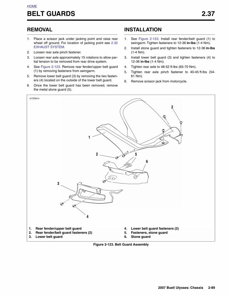
REMOVAL
1. Place a scissor jack under jacking point and raise rearwheel off ground. For location of jacking point see 2.32EXHAUST SYSTEM.
2. Loosen rear axle pinch fastener.
3. Loosen rear axle approximately 15 rotations to allow par-tial tension to be removed from rear drive system.
4. See Figure 2-123. Remove rear fender/upper belt guard(1) by removing fasteners from swingarm.
5. Remove lower belt guard (3) by removing the two fasten-ers (4) located on the outside of the lower belt guard.
6. Once the lower belt guard has been removed, removethe metal stone guard (5).
INSTALLATION
1. See Figure 2-123. Install rear fender/belt guard (1) toswingarm. Tighten fasteners to 12-36 in-lbs (1-4 Nm).
2. Install stone guard and tighten fasteners to 12-36 in-lbs(1-4 Nm).
3. Install lower belt guard (3) and tighten fasteners (4) to12-36 in-lbs (1-4 Nm).
4. Tighten rear axle to 48-52 ft-lbs (65-70 Nm).
5. Tighten rear axle pinch fastener to 40-45 ft-lbs (54-61 Nm).
6. Remove scissor jack from motorcycle.
Figure 2-123. Belt Guard Assembly
b1229a1x
1. Rear fender/upper belt guard2. Rear fender/belt guard fasteners (2)3. Lower belt guard
4. Lower belt guard fasteners (2)5. Fasteners, stone guard6. Stone guard
2
4
1
3
2
5
6
2007 Buell Ulysses: Chassis 2-89

HOME
CHIN FAIRING 2.38
REMOVAL
1. Turn wheel full right or left for easier access to center fas-teners.
2. See Figure 2-124. Remove center section fasteners andwashers (2).
3. Remove left section fasteners and washers (4).
4. Remove right section fasteners and washers (6).
5. Remove chin fairing.
NOTETo separate the left, right and center sections, drill out the riv-ets.
INSTALLATION
NOTETo join the left, right and center sections, use the rivet gunfrom a Marson Thread-SetterTM Tool Kit MODEL NO.MAR39200HD.
1. Apply LOCTITE 271 (red) on all fasteners.
2. See Figure 2-124. Position the assembled chin fairing (5)and loosely install right side fasteners and washers (6).
3. Align center section (1) and loosely install center sectionfasteners and washers (2).
NOTETurn wheel full right or left for easier access to center fasten-ers.
4. Align left section (3) and loosely install left side fastenersand washers (4).
5. Tighten all fasteners to 36-48 in-lbs (4-5 Nm).
Figure 2-124. Chin Fairing
b0942x2x
1. Center section 2. Center section fasteners and washers (2)3. Left section 4. Left section fastener and washer (2)5. Right section 6. Right section fastener and washer (2)
1
2
6
53
4
2-90 2007 Buell Ulysses: Chassis

HOME
INTAKE COVER ASSEMBLY 2.39
REMOVAL
1. Remove seat. See 2.45 SEAT.
2. See Figure 2-125. Remove fasteners and nylon washers(2).
3. Remove intake cover assembly (1).
INSTALLATION
1. Position intake cover assembly over top of air cleanercover.
NOTEFront screws go in at a slight angle.
2. See Figure 2-125. Start the front two fasteners (2) withnylon washers.
3. See Figure 2-125. Secure intake cover assembly (1) withfasteners and nylon washers (2). Tighten to 12-36 in-lbs(1.3-4 Nm).
11WARNING1WARNING
After installing seat, pull upward on front of seat to besure it is in locked position. While riding, a loose seat canshift causing loss of control, which could result in deathor serious injury. (00070a)
4. Install seat. See 2.45 SEAT.
Figure 2-125. Intake Cover Assembly
b0981x2x
1
2
1. Intake cover assembly2. Intake cover fasteners3. Intake air inlet
2
3
b1222x2x
2007 Buell Ulysses: Chassis 2-91

HOME
AIR SCOOPS 2.40
RAM AIR SCOOP
Removal1. See Figure 2-126. On left side of bike, locate ram air
scoop (4).
2. Remove three ram air scoop fasteners (3).
3. Remove ram air scoop (4).
Installation1. See Figure 2-126. Position ram air scoop (4).
2. Install ram air scoop (4) with three fasteners (3). Tightento 12-36 in-lbs (1-4 Nm).
ENGINE SHROUD AIR SCOOP
Removal1. See Figure 2-126. On right side of bike, locate engine
shroud air scoop (6).
2. Remove three engine shroud air scoop fasteners (5).
3. Remove engine shroud air scoop (6).
Installation1. See Figure 2-126. Position engine shroud air scoop (6).
2. Install engine shroud air scoop (6) with three fasteners(5). Tighten to 12-36 in-lbs (1-4 Nm).
OIL COOLER AIR SCOOP
Removal1. See Figure 2-126. On left side of bike, locate oil cooler
air scoop (2).
2. Remove two oil cooler air scoop fasteners (1).
3. Remove oil cooler air scoop (2).
Installation1. See Figure 2-126. Position oil cooler air scoop (2).
2. Apply LOCTITE 271 (red) to oil cooler air scoop fasten-ers (1) and tighten to 48-72 in-lbs (5.4-8.0 Nm).
Figure 2-126. RAM Air Scoop, Engine Shroud, Oil Cooler
b01012x2x
1. Oil cooler air scoop fastener and washer (2)2. Oil cooler air scoop3. Ram air scoop fastener and washer (3)4. Ram air scoop5. Engine scoop fastener and washer (3)6. Engine scoop
5
4
3
1
2
6
2-92 2007 Buell Ulysses: Chassis

HOME
LEFT TAIL SECTION AND BATTERY PAN 2.41
DISASSEMBLY
1. Remove seat. See 2.45 SEAT.
11WARNING1WARNING
Disconnect negative (-) battery cable first. If positive (+)cable should contact ground with negative (-) cable con-nected, the resulting sparks can cause a battery explo-sion, which could result in death or serious injury.(00049a)
2. See Figure 2-127. Unthread fastener and remove batterynegative cable (black) from battery negative (-) terminal.
3. Pull back terminal cover boot on battery positive cable(red).
4. Unthread fastener and remove battery positive cablefrom battery positive (+) terminal.
5. Remove battery.
6. Remove center tail loop. See 2.42 CENTER TAIL LOOP.
7. See Figure 2-127. Disconnect ECM connectors (4) [10],{11] and [164].
8. See Figure 2-127. Remove battery pan
a. Remove ECM (3).
NOTEWhen removing the ECM, the fastener closest to the shockassembly has a nut that is captured in the plastic shield belowthe ECM. You need to place your finger under the nut whenremoving the fastener to prevent the nut from falling out. Slidethe ECM to one side and loosely install the fastener to retainthe nut in the correct location. The rear fastener attachesdirectly to the battery pan.
b. Disconnect rear brake light switch connector [121].
c. Disconnect and remove Bank Angle Sensor (2)[134].
d. Remove fuse block and relay center (5).
e. Remove main harness and plastic grommet (7) frombattery pan.
f. Remove fasteners securing battery tray to left andright tail sections.
g. Lift battery pan straight up and out.
9. Remove fastener securing left front trunk pan to left sidetail section.
10. Remove fasteners securing left tail section to mainframe/fuel tank assembly.
11. Remove left tail section.
12. Remove the trunk pan.
a. See Figure 2-127. Remove the two fasteners secur-ing the preload adjuster to the trunk pan (13).
b. Remove the shock reservoir fastener and retainer.Push the reservoir aside to access the fastener.
c. Remove remaining fasteners securing right fronttrunk pan to right side tail sections.
d. Remove remaining components on trunk pan asneeded.
CLEANING
NOTEDo not use wheel care products or other compounds devel-oped specifically for cleaning and polishing powdercoat.These cleaners could potentially damage the tail section fin-ish.
The cast aluminum tail section has a powder coat. Becausethe surface is not bare polished aluminum, it must be cleanedusing only mild soap and warm water. After washing, alwaysdry the surface using a clean, soft cloth.
2007 Buell Ulysses: Chassis 2-93

HOME
Figure 2-127. Main Harness and Electrical Components Under Seat
8
9
1. Main harness2. BAS (bank angle sensor) connector [134}3. ECM4. ECM connectors [10] & [11]5. Fuse block and relay center6. Main harness ground wire [GRD 2]7. Main harness with plastic grommet
8. Battery ground cable9. Battery positive cable10. Left rear and right rear tail section fasteners (4)11. Seat lock cable12. Auxiliary power outlet13. Trunk pan14. Left tail section
5
11966a
1
4
6
2
10
10
12
11
13
3
14
7
2-94 2007 Buell Ulysses: Chassis
HOME
ASSEMBLY
1. See Figure 2-127. Install trunk pan assembly (13) fromleft side of vehicle.
2. Install fastener securing right front trunk pan to right sidetail section and tighten to 12-36 in-lbs (1.3-4 Nm).
3. Install shock reservoir, retainer and fastener. Tighten fas-tener to 80-88 in-lbs (9.0-9.9 Nm).
4. Install left tail section (14) onto vehicle.
a. Apply LOCTITE 271 (red) and install fastenersattaching left tail section to main frame/fuel tankassembly and tighten to 21-23 ft-lbs (28.5-31.2 Nm).
b. Install fastener attaching left front trunk pan to leftside tail section and tighten to 12-36 in-lbs (1.3-4Nm).
5. Install two fasteners securing the preload adjuster to thetrunk pan and tighten to 36-60 in-lbs (4-6.7 Nm).
6. Install battery pan:
a. Install fasteners securing battery tray to left and righttail sections and tighten to 72-96 in-lbs (8-11 Nm).
b. Install fuse block and relay center (5).
c. Install main harness and plastic grommet (7) intobattery pan.
d. Install bank angle sensor (2), connect and tightenfastener to 12-36 in-lbs (1.3-4 Nm).
e. Connect rear brake light switch connector [121].
f. Install ECM and tighten fasteners to 36-60 in-lbs (4-6.7 Nm).
7. See Figure 2-127. Connect ECM connectors (4) [10],[11] and [164].
8. Install center tail loop. See 2.42 CENTER TAIL LOOP.
11WARNING1WARNING
Connect positive (+) battery cable first. If positive (+)cable should contact ground with negative (-) cable con-nected, the resulting sparks can cause a battery explo-sion, which could result in death or serious injury.(00068a)
9. Install battery. See 7.11 BATTERY.
11WARNING1WARNING
After installing seat, pull upward on front of seat to besure it is in locked position. While riding, a loose seat canshift causing loss of control, which could result in deathor serious injury. (00070a)
10. Install seat. See 2.45 SEAT.
2007 Buell Ulysses: Chassis 2-95

HOME
Figure 2-128. Tail Frame and Trunk Pan Assembly
1. Fastener, washer and nut to main frame/fuel tank assembly (4)2. Right tail section3. Center tail loop4. Center tail loop fastener to rear tail section (4)5. Left tail section6. Ground terminal fastener (2)7. Front trunk pan fastener to side tail section (2)8. Seat latch assembly9. Trunk pan assembly10. Rear trunk pan fastener to center tail loop (2)11. Battery pan
b0956x2x
3
9
7
65
1
2
4
8
11
10
2-96 2007 Buell Ulysses: Chassis

HOME
CENTER TAIL LOOP 2.42
DISASSEMBLY
1. Remove seat. See 2.45 SEAT.
11WARNING1WARNING
Disconnect negative (-) battery cable first. If positive (+)cable should contact ground with negative (-) cable con-nected, the resulting sparks can cause a battery explo-sion, which could result in death or serious injury.(00049a)
2. Unthread fastener and remove battery negative cable(black) from battery negative (-) terminal.
3. See Figure 2-129. Remove two fasteners securing trunkpan to center tail loop (1).
4. Remove cable strap from wire harness and seat latchcable.
5. See Figure 2-129. Remove wire cover (3) on bottom sideof license plate bracket (2) in order to access wires.
6. Disconnect:
a. Right turn signal connector [18]
b. Left turn signal connector [19]
c. License plate lamp connector [45]
d. Tail light connectors [93]
e. Auxiliary power outlet [180]
7. Remove two fasteners (10) securing trunk pan to centertail loop.
8. Remove fasteners securing left and right tail sections tocenter tail loop.
9. Remove center tail loop from vehicle.
10. To further disassemble center tail loop see 7.13 TAILLAMP, 7.14 LICENSE PLATE LAMP ASSEMBLY, 7.15TURN SIGNALS and 2.48 TRIPLE TAIL.
ASSEMBLY
1. Install center tail loop around left and right tail sections.
2. Install fasteners securing left and right tail sections tocenter tail loop but do not tighten.
3. Install two fasteners securing trunk pan to center tail loopbut do not tighten.
4. Route wire harness and auxiliary power outlet under seatlatch bracket.
5. Tighten nuts of left and right tail sections to 20-22 ft-lbs(27-30 Nm). Repeat to verify torque.
6. Connect:
a. Right turn signal connector [18].
b. Left turn signal connector [19].
c. License plate lamp connector [45]
d. Tail light connectors [93].
e. Auxiliary power outlet [180]
7. Install cable strap.
8. Install wire cover (3) on bottom side of tail loop (1) andlicense plate bracket (2).
9. Tighten fasteners.
a. Wire cover screws to 36-48 in-lbs (4-5.4 Nm).
b. Install license plate light fasteners and to 12-36 in-lbs (1.4-4 Nm).
11WARNING1WARNING
Connect positive (+) battery cable first. If positive (+)cable should contact ground with negative (-) cable con-nected, the resulting sparks can cause a battery explo-sion, which could result in death or serious injury.(00068a)
10. Connect battery by threading negative cable (black) intothreaded hole tightening to 72-96 in-lbs (8-11 Nm). See1.4 BATTERY MAINTENANCE.
11WARNING1WARNING
After installing seat, pull upward on front of seat to besure it is in locked position. While riding, a loose seat canshift causing loss of control, which could result in deathor serious injury. (00070a)
11. Install seat. See 2.45 SEAT.
Figure 2-129. Wire Cover/Tail Loop/License Plate Bracket
1. Tail loop2. License plate bracket3. Wire cover
1
2
3
b1230x1x
2007 Buell Ulysses: Chassis 2-97

HOME
RIGHT TAIL SECTION 2.43
DISASSEMBLY
1. Remove seat. See 2.45 SEAT.
11WARNING1WARNING
Disconnect negative (-) battery cable first. If positive (+)cable should contact ground with negative (-) cable con-nected, the resulting sparks can cause a battery explo-sion, which could result in death or serious injury.(00049a)
NOTEThe center tail loop must be removed before removing the leftor right tail sections. See 2.42 CENTER TAIL LOOP.
2. See 7.11 BATTERY Unthread fastener and remove bat-tery negative cable (black) from battery negative (-) ter-minal.
3. Pull back terminal cover boot on battery positive cable(red).
4. Unthread fastener and remove battery positive cablefrom battery positive (+) terminal.
5. Remove battery.
NOTEWhen removing the ECM, the fastener closest to the shockassembly has a nut that is captured in the plastic shield belowthe ECM. You need to place your finger under the nut whenremoving the fastener to prevent the nut from falling out. Slidethe ECM to one side and loosely install the fastener to retainthe nut in the correct location. The rear fastener attachesdirectly to the battery pan.
6. Remove ECM.
7. Remove rear shock reservoir fastener and retainer.
8. Disconnect the rear brake light switch.
9. Move the rear shock reservoir out of the way in order toaccess right tail section fastener.
10. Remove the rear brake master cylinder reservoir.
11. See Figure 2-131. Remove the three fasteners on theinside of the right tail section.
12. See Figure 2-132. Remove the final two fasteners on theoutside of the right tail section and remove the right sidetail section.
Figure 2-130. ECM Fastener with Captured Nut
12068a
Figure 2-131. Internal Fasteners/Right Side Tail Section
Figure 2-132. Front Outside FastenersRight Side Tail Section
12077
12078
2-98 2007 Buell Ulysses: Chassis

HOME
ASSEMBLY
1. See Figure 2-128. Install right tail section (2) onto vehi-cle.
a. Install fastener (1) attaching right front trunk pan toright side tail section and tighten to 12-36 in-lbs(1.3-4 Nm).
b. Install fasteners (5) attaching right rear tail section tocenter tail loop and tighten to 20-22 ft-lbs (27.1-29.8Nm).
c. Apply LOCTITE 271 (red) and install fastenersattaching right tail section to main frame/fuel tankassembly and tighten to 21-23 ft-lbs (28.5-31.2 Nm).
d. Install battery tray and ground wire fasteners andtighten to 72-96 in-lbs (8-10.8 Nm).
2. Install master cylinder remote reservoir. See 2.13 REARBRAKE MASTER CYLINDER.
3. Install shock reservoir, retainer, and fastener. Tighten to80-88 in-lbs (9.0-9.9 Nm).
4. Connect rear brake light switch connector [121].
5. Install ECM and tighten fasteners to 36-60 in-lbs (4.0-6.8 Nm).
11WARNING1WARNING
Connect positive (+) battery cable first. If positive (+)cable should contact ground with negative (-) cable con-nected, the resulting sparks can cause a battery explo-sion, which could result in death or serious injury.(00068a)
6. Install battery by threading positive cable (red) intothreaded hole first tightening to 72-96 in-lbs (8-11 Nm).See 1.4 BATTERY MAINTENANCE.
11WARNING1WARNING
After installing seat, pull upward on front of seat to besure it is in locked position. While riding, a loose seat canshift causing loss of control, which could result in deathor serious injury. (00070a)
7. Install seat. See 2.45 SEAT.
2007 Buell Ulysses: Chassis 2-99

HOME
WINDSHIELD AND WINDSCREEN 2.44
REMOVAL
NOTES● The windshield releases from the windscreen by pulling
outward and away from vehicle.
● The windscreen fastens into the left and right front mod-ules (2, 8) and the center fairing support (6).
1. See Figure 2-133. Remove windshield (4) by pullingloose from windscreen (6).
2. Remove six windscreen fasteners (5).
3. Remove windscreen (6).
INSTALLATION
1. See Figure 2-133. Position windscreen (6) onto left andright front modules (2, 8) and the center fairing support(6).
2. Install six fasteners and tighten to 10-12 in-lbs (1.1-1.4Nm).
3. Install windscreen (4) by pushing into place. Pull onwindscreen when installed to verify attachment.
Figure 2-133. Windshield and Windscreen
1. Headlight mounting bracket2. Left front module3. Windscreen fastener (4)4. Windshield5. Windscreen fasteners (6)6. Windscreen7. Fairing support, center8. Right front module
1
2
34
6
7
8
b1198a7x
5
2-100 2007 Buell Ulysses: Chassis

HOME
SEAT 2.45
GENERAL
See Figure 2-134. The seat anchors in six places on the vehi-cle. The first is a front tab (1) which fits into a slot in the frame.Four seats hooks (2) slide onto the shouldered lugs located inthe left and right forward tail sections. The last is the seat locklatch which fits into the slot on the seat latch.
REMOVAL
1. Insert ignition key into seat lock located at rear of motor-cycle below taillight.
2. Turn key clockwise to disengage rear seat latch.
3. Grip the rear of the seat and pull towards the rear of themotorcycle.
INSTALLATION
11WARNING1WARNING
After installing seat, pull upward on front of seat to besure it is in locked position. While riding, a loose seat canshift causing loss of control, which could result in deathor serious injury. (00070a)
1. See Figure 2-134. Position seat and slide forward toengage the front tab (1) with the slot in the frame and thefour hooks (2) with the shouldered lugs on the tail sec-tions.
2. Align rear tab with latch slot at rear of motorcycle.
3. Press down firmly on rear of seat to engage seat locklatch (3).
4. Pull up on rear of seat to make sure latch is engaged.
5. Remove ignition key from seat lock.
Figure 2-134. Seat Attachments
1. Front tab2. Seat hook3. Seat lock latch
1
2
2
2
2
3
11788
2007 Buell Ulysses: Chassis 2-101

HOME
SEAT LOCK 2.46
REMOVAL
1. Remove seat. See 2.45 SEAT.
2. Cut cable strap securing wire harness to seat lock cable.
3. See Figure 2-135. Disconnect seat lock cable (5):
a. Remove latch (8) from latch bracket (9) by removingtwo fasteners (7).
b. Remove cable end (6) and cable (5) from latch (8).
4. Remove seat lock:
a. Remove wire cover from bottom side of license platebracket to access seat lock.
b. Remove seat lock retainer (3) from seat lock (1).
c. Remove seat lock (1) from plate (2) and licenseplate bracket.
NOTEWhen removing seat lock (1), cable end (4) should releasefrom seat lock.
5. Remove cable (5) from plate (2).
INSTALLATION
1. See Figure 2-135. Install cable (5) into plate (2).
2. Install the seat lock (1) into license plate bracket andplate (2).
NOTES● Once seat lock has been started through the hole in the
license plate bracket and plate (2), now is the time toconnect the cable end to the seat lock.
● Seat lock plate must be aligned to tab on seat lock forproper installation.
3. Install seat lock retainer (3) by aligning retainer toretainer grooves on back side of seat lock (1).
4. Connect seat lock cable to latch:
a. Install cable end (6) and cable (5) onto latch (8).
b. Install latch (8) to latch bracket (9) and tighten fas-teners (7) to 60-96 in-lbs (6.7-10.8 Nm).
5. Open and close the seat lock with ignition key to verifythat cable is working properly.
6. Install the wire cover fasteners and tighten to 36-48 in-lbs (4-5.4 Nm).
7. Install license plate light fasteners and tighten to 12-36in-lbs (1.3-4 Nm)
11WARNING1WARNING
After installing seat, pull upward on front of seat to besure it is in locked position. While riding, a loose seat canshift causing loss of control, which could result in deathor serious injury. (00070a)
8. Install cable strap around seat lock cable in original loca-tion.
9. Install seat. See 2.45 SEAT.
2-102 2007 Buell Ulysses: Chassis

HOME
Figure 2-135. Seat Lock Assembly
1. Seat lock2. Plate3. Retainer4. Cable end5. Cable6. Cable end7. Latch screw (metric) (2)8. Latch9. Latch bracket10. Trunk pan11. Center tail loop
4
7
11
6
b1214x2x
1
2
3
5
8
9
10
2007 Buell Ulysses: Chassis 2-103

HOME
SIDESTAND 2.47
GENERAL
1CAUTION
This motorcycle does NOT have a locking sidestand.Park the motorcycle on a level, firm surface. An unbal-anced motorcycle can fall, which could result in death orserious injury. (00122a)
The sidestand is located on the left side of the motorcycle.The sidestand swings outward to support the motorcycle forparking.
REMOVAL
1. Remove muffler. See Muffler and Straps in 2.32EXHAUST SYSTEM.
2. See Figure 2-137. Remove fasteners (4) securing side-stand bracket (3) to engine.
3. Remove sidestand.
DISASSEMBLY
NOTESidestand assembly does not have to be removed frommotorcycle in order to remove sidestand leg.
1. Remove two fasteners from the left side of chin fairing.See 2.38 CHIN FAIRING.
2. See Figure 2-137. Remove sidestand leg (1).a. Retract sidestand leg.
b. Remove sidestand spring (2) and spring extensionplate (4) using SNAP-ON SPRING TOOL (Part No.HE-52B).
c. Remove sidestand pivot pin circlip (7) and removesidestand pivot pin (3).
3. Extend sidestand leg and remove.
Figure 2-136. Sidestand, Retracted
10309
Figure 2-137. Sidestand Assembly (Extended)
b0946g2x
3
2
1
4
5
6
7
1. Leg2. Spring3. Pivot pin4. Extension plate5. Bracket6. Bracket fastener (2)7. Pivot pin circlip
2-104 2007 Buell Ulysses: Chassis
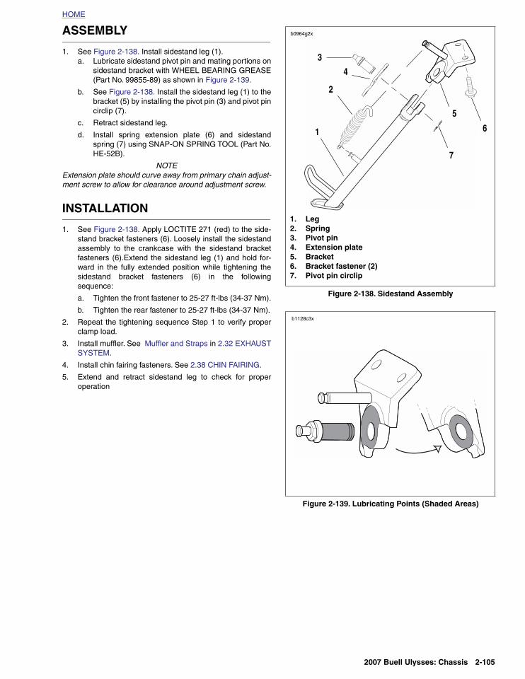
HOME
ASSEMBLY
1. See Figure 2-138. Install sidestand leg (1).a. Lubricate sidestand pivot pin and mating portions on
sidestand bracket with WHEEL BEARING GREASE(Part No. 99855-89) as shown in Figure 2-139.
b. See Figure 2-138. Install the sidestand leg (1) to thebracket (5) by installing the pivot pin (3) and pivot pincirclip (7).
c. Retract sidestand leg.
d. Install spring extension plate (6) and sidestandspring (7) using SNAP-ON SPRING TOOL (Part No.HE-52B).
NOTEExtension plate should curve away from primary chain adjust-ment screw to allow for clearance around adjustment screw.
INSTALLATION
1. See Figure 2-138. Apply LOCTITE 271 (red) to the side-stand bracket fasteners (6). Loosely install the sidestandassembly to the crankcase with the sidestand bracketfasteners (6).Extend the sidestand leg (1) and hold for-ward in the fully extended position while tightening thesidestand bracket fasteners (6) in the followingsequence:
a. Tighten the front fastener to 25-27 ft-lbs (34-37 Nm).
b. Tighten the rear fastener to 25-27 ft-lbs (34-37 Nm).
2. Repeat the tightening sequence Step 1 to verify properclamp load.
3. Install muffler. See Muffler and Straps in 2.32 EXHAUSTSYSTEM.
4. Install chin fairing fasteners. See 2.38 CHIN FAIRING.
5. Extend and retract sidestand leg to check for properoperation
Figure 2-138. Sidestand Assembly
Figure 2-139. Lubricating Points (Shaded Areas)
1. Leg2. Spring3. Pivot pin4. Extension plate5. Bracket6. Bracket fastener (2)7. Pivot pin circlip
b0946x2x
3
b0964g2x
2
1
4
5
6
7
b1128c3x
2007 Buell Ulysses: Chassis 2-105

HOME
TRIPLE TAIL 2.48
GENERAL
See Figure 2-140. The Triple TailTM when folded forward actsas a luggage rack (1) with integrated tie-down hooks. When inthe upright position, it is a passenger backrest (2) with subtleflex for passenger comfort. When in the rearward position,you can carry a passenger and have a luggage rack (3) forextra carrying capacity.
REMOVAL
NOTEThe portion of the grab handle closest to the front of the vehi-cle is slotted for easy access. The fastener does not need tobe fully removed.
1. Remove the seat. Refer to 2.45 SEAT.
2. See Figure 2-141. To access fasteners (3, 11), removethe plastic wire cover under the license plate light.Remove the two screws and the two nuts to remove theplastic cover.
3. Remove the right hand (RH) rear fastener (3).
4. Loosen but do not remove the front (RH) fastener (1).
5. Hold the triple tail rack (5) in place and remove the RHgrab handle (2).
6. Slowly, slide the tail towards the right.
NOTEThe spring (6) in the left hand (LH) grab handle is held undertension.
7. Loosen but do not remove the front (LH) fastener (12).
8. Remove rear fastener (11) and the LH grab handle (13).
DISASSEMBLY
1. See Figure 2-141. Remove the fastener (9) and the plas-tic collar (10) from the LH grab handle(13).
2. To remove the bearings (4) from the right hand grab han-dle, insert a 3/4 in. blind bearing collet and extract.
3. To remove the bearing (4) from the LH grab handle,insert a 3/4 in. blind bearing collet and extract.
4. Remove the pin (7) and detent (8).
5. Inspect and replace the spring, pin and detent as neces-sary.
NOTEReplace the bushing with a new bushing if removed from thegrab handle.
ASSEMBLY
1. Hold the RH grab handle and using a Snap-on seal andbushing driver, tap in the bearing.
2. Hold the LH grab handle to assemble the detent and pin.
3. Using a Snap-on seal and bushing driver, tap in the bear-ing.
Figure 2-140. Triple Tail Positions
12268
12269
12270
1. Forward luggage rack2. Passenger backrest3. Rearward luggage rack
2
3
1
2-106 2007 Buell Ulysses: Chassis

HOME
INSTALLATION
1. Install the LH grab handle unto the front fastener andinstall the rear fastener. Do not tighten.
2. Slide the spring into the LH grab handle.
3. Press the spring with the shaft of the triple tail rack andhold the rack in place capturing the spring.
4. Install the plastic collar (10) and tighten the fastener to36-48 in-lbs (4.0-5.4 Nm).
5. Holding the rack, fit the RH grab handle unto the frontfastener and install the rear fastener. Do not tighten.
6. See Figure 2-141. Apply LOCTITE 271 (red) to LH andRH grab handle fasteners.
a. Tighten rear fasteners (3, 11) to 23-25 ft-lbs (31-34Nm). Tighten
b. Tighten front fasteners (1, 12) to 96-120 in-lbs (11-13.5 Nm).
7. Verify that the rack operates properly.
8. Install the plastic wire cover under the license plate lamp.Tighten the screws to 36-48 in-lbs (4.0-5.4 Nm) andtighten the nuts to 12-36 in-lbs (1.4-4.0 Nm).
Figure 2-141. Triple Tail, Passenger Backrest and Luggage Rack
1. Front fastener, grab handle2. RH grab handle3. Rear fastener with washer, grab handle4. Bearing (2)5. Tail rack6. Spring7. Pin
8. Detent, tail rack9. Screw, collar10. Collar, tail rack11. Rear fastener with washer, grab handle12. Front fastener, grab handle13. LH grab handle14. Tail loop
b1188x2x
14
2
1
3
4
5
46
7
8
10
9
11
13
12
2007 Buell Ulysses: Chassis 2-107

HOME
NOTES
2-108 2007 Buell Ulysses: Chassis