FOREWORD - R6 Message net.com This Supplementary Service Manual has been prepared to introduce new...
26
Transcript of FOREWORD - R6 Message net.com This Supplementary Service Manual has been prepared to introduce new...


FOREWORDThis Supplementary Service Manual has been prepared to introduce new service and data for theYZF-R6 2001. For complete service information procedures it is necessary to use this SupplementaryService Manual together with the following manual.
YZF-R6 ’99 SERVICE MANUAL: 5EB1-AE1YZF-R6 (L) 2000 SUPPLEMENTARY SERVICE MANUAL: 5EB1-AE2
YZF-R6 2001SUPPLEMENTARYSERVICE MANUAL
2000 by Yamaha Motor Co., Ltd.First Edition, September 2000
All rights reserved.Any reproduction or unauthorized use
without the written permission ofYamaha Motor Co., Ltd. is expressly
prohibited.

NOTE:
WARNING
CAUTION:
EB001000
NOTICEThis manual was produced by the Yamaha Motor Company, Ltd. primarily for use by Yamaha dealersand their qualified mechanics. It is not possible to include all the knowledge of a mechanic in one manu-al, so it is assumed that anyone who uses this book to perform maintenance and repairs on Yamahamotorcycles has a basic understanding of the mechanical ideas and the procedures of motorcyclesrepair.Repairs attempted by anyone without this knowledge are likely to render the motorcycles unfit for use.
Yamaha Motor Company, Ltd. is continually striving to improve all its models. Modifications and signifi-cant changes in specifications or procedures will be forwarded to all authorized Yamaha dealers andwill appear in future editions of this manual where applicable.
Designs and specifications are subject to change without notice.
IMPORTANT INFORMATIONParticularly important information is distinguished in this manual by the following.
The Safety Alert Symbol means ATTENTION! BECOME ALERT! YOURSAFETY IS INVOLVED!
Failure to follow WARNING instructions could result in severe injury or death tothe motorcycle operator, a bystander or a person inspecting or repairing themotorcycle.
A CAUTION indicates special precautions that must be taken to avoid damageto the motorcycle.
NOTE: A NOTE provides key information to make procedures easier or clearer.

7
2 1 4 3
8
6
5
YP002000
HOW TO USE THIS MANUALThis manual is intended as a handy, easy-to-read reference book for the mechanic. Comprehensiveexplanations of all installation, removal, disassembly, assembly, repair and inspection procedures arelaid out with the individual steps in sequential order.
1 The manual is divided into chapters. An abbreviation and symbol in the upper right corner of eachpage indicate the current chapter. Refer to “SYMBOLS” on the following page.
2 Each chapter is divided into sections. The current section title is shown at the top of each page,except in Chapter 3 (“Periodic Inspections and Adjustments”), where the sub-section title (-s) appear.
(In Chapter 3, “Periodic Inspections and Adjustments”, the sub-section title appears at the top of eachpage, instead of the section title.)
3 Sub-section titles appear in smaller print than the section title.
4 To help identify parts and clarify procedure steps, there are exploded diagrams at the start of eachremoval and disassembly section.
5 Numbers are given in the order of the jobs in the exploded diagram. A circled number indicates adisassembly step.
6 Symbols indicate parts to be lubricated or replaced (see “SYMBOLS”).
7 A job instruction chart accompanies the exploded diagram, providing the order of jobs, names ofparts, notes in jobs, etc.
8 Jobs requiring more information (such as special tools and technical data) are described sequen-tial0ly.

22
1
3
5
7
9
2
4
8
6
24 25
2321
19 2018
15
1413
11 12
10
GENINFO SPEC
ENG
CARB
ELEC
CHKADJ
TRBLSHTG
16 17
COOL
CHAS
EB003000
SYMBOLSThe following symbols are not relevant to everyvehicle.Symbols 1 to 9 indicate the subject of eachchapter.1 General information2 Specifications3 Periodic checks and adjustment4 Engine5 Cooling system6 Carburetor(-s)7 Chassis8 Electrical system9 Troubleshooting
Symbols 10 to 17 indicate the following.10 Serviceable with engine mounted11 Filling fluid12 Lubricant13 Special tool14 Tightening torque15 Wear limit, clearance16 Engine speed17 Electrical data
Symbols 18 to 23 in the exploded diagrams indi-cate the types of lubricants and lubricationpoints.18 Apply engine oil19 Apply gear oil20 Apply molybdenum disulfide oil21 Apply wheel bearing grease22 Apply lightweight lithium-soap base grease23 Apply molybdenum disulfide grease
Symbols 24 to 25 in the exploded diagrams indi-cate the following:24 Apply locking agent (LOCTITE )25 Use new one
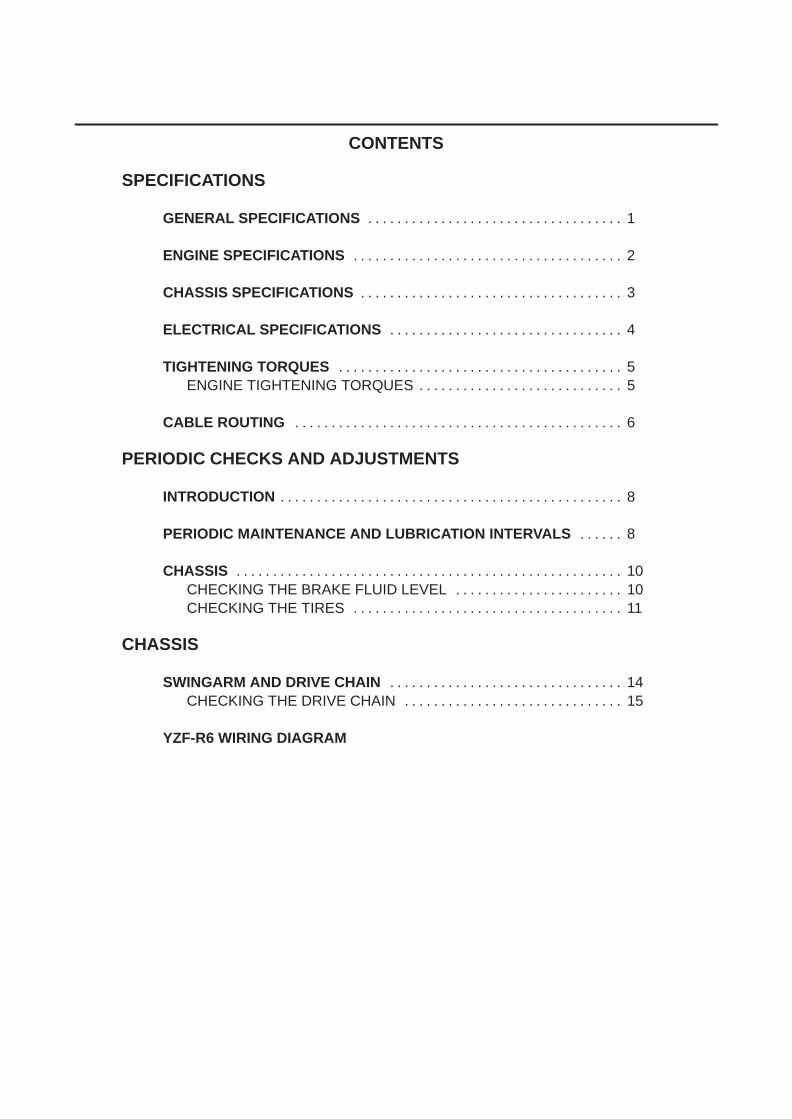
CONTENTS
SPECIFICATIONS
GENERAL SPECIFICATIONS 1. . . . . . . . . . . . . . . . . . . . . . . . . . . . . . . . . . .
ENGINE SPECIFICATIONS 2. . . . . . . . . . . . . . . . . . . . . . . . . . . . . . . . . . . . .
CHASSIS SPECIFICATIONS 3. . . . . . . . . . . . . . . . . . . . . . . . . . . . . . . . . . . .
ELECTRICAL SPECIFICATIONS 4. . . . . . . . . . . . . . . . . . . . . . . . . . . . . . . .
TIGHTENING TORQUES 5. . . . . . . . . . . . . . . . . . . . . . . . . . . . . . . . . . . . . . . ENGINE TIGHTENING TORQUES 5. . . . . . . . . . . . . . . . . . . . . . . . . . . .
CABLE ROUTING 6. . . . . . . . . . . . . . . . . . . . . . . . . . . . . . . . . . . . . . . . . . . . .
PERIODIC CHECKS AND ADJUSTMENTS
INTRODUCTION 8. . . . . . . . . . . . . . . . . . . . . . . . . . . . . . . . . . . . . . . . . . . . . . .
PERIODIC MAINTENANCE AND LUBRICATION INTERVALS 8. . . . . .
CHASSIS 10. . . . . . . . . . . . . . . . . . . . . . . . . . . . . . . . . . . . . . . . . . . . . . . . . . . . . CHECKING THE BRAKE FLUID LEVEL 10. . . . . . . . . . . . . . . . . . . . . . . CHECKING THE TIRES 11. . . . . . . . . . . . . . . . . . . . . . . . . . . . . . . . . . . . .
CHASSIS
SWINGARM AND DRIVE CHAIN 14. . . . . . . . . . . . . . . . . . . . . . . . . . . . . . . . CHECKING THE DRIVE CHAIN 15. . . . . . . . . . . . . . . . . . . . . . . . . . . . . .
YZF-R6 WIRING DIAGRAM


–1–
GENERAL SPECIFICATIONS SPEC
SPECIFICATIONSGENERAL SPECIFICATIONS
Item Standard Limit
Model code 5MT1 (N) (D) (B) (GB) (GR) (DK) (NL) (S) (I) (E)5MT2 (N) (D) (A) (SF)5MT3 (F)5MT4 (AUS) (NZ)
DimensionsOverall length
Overall widthOverall heightSeat heightWheelbaseMinimum ground clearanceMinimum turning radius
2025 mm (except for N, S, F, AUS, NZ)2080 mm (for N, S, F, AUS, NZ)690 mm1105 mm820 mm1380 mm135 mm3400 mm
WeightWet (with oil and a full fuel tank)
Dry (without oil and fuel)
Maximum load (total of cargo, rider,passenger, and accessories)
186 kg
167 kg
375 kg

–2–
ENGINE SPECIFICATIONS SPEC
ENGINE SPECIFICATIONS
Item Standard Limit
CamshaftsDrive systemCamshaft cap inside diameterCamshaft journal diameterCamshaft-journal-to-camshaftcapclearance
Chain drive (right)23.000 23.021 mm22.967 22.980 mm0.028 0.064 mm
0.08 mm
CarburetorsModel (manufacturer) quantityThrottle cable free play (at theflange of the throttle grip)ID markMain jet
Main air jetJet needle
Needle jetPilot air jetPilot outletPilot jetBypass 1Bypass 2Bypass 3Pilot screw turns outValve seat sizeStarter jet 1Starter jet 2Butterfly valve sizeFuel level (below the line on thefloat chamber)
CVRD37 (KEIHIN) 46 8 mm
5EB00, 5EB200 (G), 5EB300 (F)Carburetors 1 and 4: #152Carburetors 2 and 3: #148#110Carburetors 1 and 4: N7RACarburetors 2 and 3: N7SA2.6#1100.9#380.80.80.81-1/2 21.2#500.6#11017.5 18.5 mm
–3–
CHASSIS SPECIFICATIONS SPEC
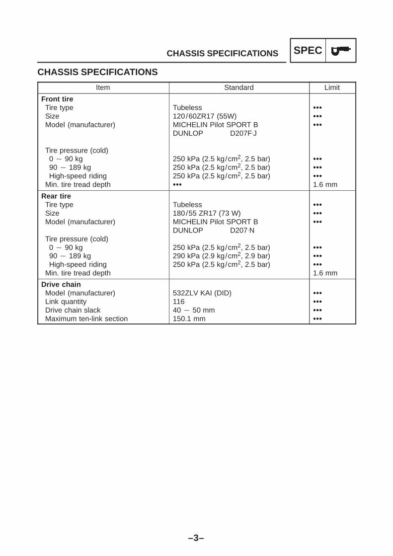
CHASSIS SPECIFICATIONS
Item Standard Limit
Front tireTire typeSizeModel (manufacturer)
Tire pressure (cold)0 90 kg90 189 kgHigh-speed riding
Min. tire tread depth
Tubeless120/60ZR17 (55W)MICHELIN Pilot SPORT BDUNLOP D207F.J
250 kPa (2.5 kg/cm2, 2.5 bar)250 kPa (2.5 kg/cm2, 2.5 bar)250 kPa (2.5 kg/cm2, 2.5 bar)
1.6 mm
Rear tireTire typeSizeModel (manufacturer)
Tire pressure (cold)0 90 kg90 189 kgHigh-speed riding
Min. tire tread depth
Tubeless180/55 ZR17 (73 W)MICHELIN Pilot SPORT BDUNLOP D207.N
250 kPa (2.5 kg/cm2, 2.5 bar)290 kPa (2.9 kg/cm2, 2.9 bar)250 kPa (2.5 kg/cm2, 2.5 bar)
1.6 mm
Drive chainModel (manufacturer)Link quantityDrive chain slackMaximum ten-link section
532ZLV KAI (DID)11640 50 mm150.1 mm

–4–
ELECTRICAL SPECIFICATIONS SPEC
ELECTRICAL SPECIFICATIONS
Item Standard Limit
Ignition systemIgnition system typeIgnition timingAdvanced timingAdvancer typePickup coil resistance/colorTransistorized coil ignition unit model
(manufacturer)
C.D.I.10 BTDC at 1300 r/min55 BTDC at 5250 r/minThrottle position sensor and electrical248 372 Ω/Gy-BF8T383 (MITSUBISHI)
BatteryBattery typeBattery voltage/capacity
GT9B-412 V/8 AH
Bulbs (voltage/wattage quantity)HeadlightAuxiliary lightTail /brake lightTurn signal lightLicense plate lightMeter light
12 V 60 W/55 W 212 V 5 W 213.5 V 6.1 W/1 W 20 (LED)12 V 21 W 412 V 5 W 112 V 1.4 W 2
Sidestand relayModelCoil resistance
G8R-30Y-M162 198 Ω
Fuel pump relay model (manufacturer)Resistance
G8R-30Y-M (OMRON)162 198 Ω
Fuses (amperage quantity)Main fuseHeadlight fuseSignaling system fuseIgnition fuseRadiator fan fuseBackup fuse (odometer)Reserve
30 A 120 A 120 A 115 A 17.5 A 17.5 A 130 A 120 A 115 A 17.5 A 1

–5–
TIGHTENING TORQUES SPEC
ENGINE TIGHTENING TORQUES
Item Fastener Threadsize
Q’tyTightening
torque Remarkssize
Q yNm mkg
Cap bolt (timing chain tensioner)Neutral switch
BoltScrew
M6M6
12
720
0.72.0

–6–
CABLE ROUTING SPEC
A Fasten the battery box and starter motor lead with a plastic clamp.B Fasten the wire positive lead and starter motor lead with clamp at the
end of the cover of the battery positive terminal.The end of the clamp is facing frontward.
C Route the under of the CDI unit coupler.D Clamp the lead at the rear of the two holes.E Route the leads into the hole.F Route the lead along the inside of the two ribs.G Route the license plate light lead and taillight lead along the outside of
the battery box so that the leads do not get caught between the rib ofthe battery box and the fender.
1 Reservoir tank2 Fuse box3 Tool kit4 Wire minus lead5 Wire harness6 Battery box7 Frame
EB206000
CABLE ROUTING

–7–
O Fasten the main harness, ground lead and batterybox with a plastic clamp.
P The end of the clamp is facing upward.Q The end of the clamp is facing upward.R Licence and flasher light sub harness on the
taillight unit.S Licence and flasher light sub harness on the
taillight unit.T Clamp the leads.U Store the ends of all leads at the inside of the rib.V Fasten the licence light lead. And bend the licence
light lead.W Fasten the flasher light lead. And bend the flasher
light lead.
CABLE ROUTING SPEC
H Route the seat lock cable into the hole of the frame.Mount the cable so that the side covered with acable protector up the end is positioned at rear.
I Fasten the seat lock cable with a steel clamp.J Do not fasten the seat lock cable.K Route the wire negative lead under the starter relay
lead.L Fasten the main harness, starter relay lead and
wire negative lead with a plastic clamp.M Route the wire negative lead under the main
harness.N Position the wire negative lead coupler under the
main harness.

–8–
INTRODUCTION/PERIODIC MAINTENANCE ANDLUBRICATION INTERVALS
CHKADJ
NOTE:
EB300000
PERIODIC CHECKS AND ADJUSTMENTSINTRODUCTIONThis chapter includes all information necessary to perform recommended checks and adjustments. Iffollowed, these preventive maintenance procedures will ensure more reliable vehicle operation, alonger service life and reduce the need for costly overhaul work. This information applies to vehiclesalready in service as well as to new vehicles that are being prepared for sale. All service techniciansshould be familiar with this entire chapter.EB301000
PERIODIC MAINTENANCE AND LUBRICATION INTERVALS
The annual checks must be performed every year, except if a kilometer-based maintenance isperformed instead.
From 50,000 km, repeat the maintenance intervals starting from 10,000 km. Items marked with an asterisk should be performed by a Yamaha dealer as they require specialtools, data and technical skills.
NO ITEM CHECK OR MAINTENANCE JOBODOMETER READING ( 1,000 km) ANNUALNO. ITEM CHECK OR MAINTENANCE JOB1 10 20 30 40
ANNUALCHECK
1 * Fuel line Check fuel hoses for cracks or damage. √ √ √ √ √
2 * Fuel filter Check condition. √ √
3 Spark plu gs
Check condition. Clean and regap.
√ √3 Spark plugs
Replace. √ √
4 * Valves Check valve clearance. Adjust.
Every 40,000 km
5 Air filter element Clean. √ √
5 Air filter element Replace. √ √
6 Clutch Check operation. Adjust.
√ √ √ √ √
7 * Front brake
Check operation, fluid level and vehicle for fluid leakage.(See NOTE)
√ √ √ √ √ √7 Front brake
Replace brake pads. Whenever worn to the limit
8 * Rear brake
Check operation, fluid level and vehicle for fluid leakage.(See NOTE)
√ √ √ √ √ √8 Rear brake
Replace brake pads. Whenever worn to the limit
9 * Brake hoses Check for cracks or damage. √ √ √ √ √
9 * Brake hoses Replace (See NOTE) Every 4 years
10 * Wheels Check runout and for damage. √ √ √ √
11 * Tires
Check tread depth and for damage. Replace if necessary. Check air pressure. Correct if necessary.
√ √ √ √
12 * Wheel bearings Check bearing for looseness or damage. √ √ √ √
13 * Swingarm Check operation and for excessive play. √ √ √ √
13 * Swingarm Lubricate with lithium-soap-based grease. Every 50,000 km
14 Drive chain Check chain slack. Make sure that the rear wheel is properly aligned. Clean and lubricate.
Every 1,000 km and after washingthe motorcycle or riding in the rain.
15 * Steering bearings Check bearing play and steering for roughness. √ √ √ √ √
Lubricate with lithium-soap-based grease. Every 20,000 km
16 * Chassis fasteners Make sure that all nuts, bolts and screws are properly
tightened.√ √ √ √ √

–9–
INTRODUCTION/PERIODIC MAINTENANCE ANDLUBRICATION INTERVALS
CHKADJ
NOTE:
NO ITEM CHECK OR MAINTENANCE JOBODOMETER READING ( 1,000 km) ANNUALNO. ITEM CHECK OR MAINTENANCE JOB1 10 20 30 40
ANNUALCHECK
17 Sidestand Check operation. Lubricate.
√ √ √ √ √
18 * Sidestand switch Check operation. √ √ √ √ √ √
19 * Front fork Check operation and for oil leakage. √ √ √ √
20 *Rear shock absorberassembly
Check operation and shock absorber for oil leakage. √ √ √ √
21 *
Rear suspensionrelay arm and
Check operation. √ √ √ √21 *
relay arm and connecting armpivoting points Lubricate with lithium-soap-based grease. √ √
22 * Carburetors Check starter (choke) operation. Adjust engine idling speed and synchronization.
√ √ √ √ √ √
23 Engine oil Change. √ √ √ √ √ √
24Engine oil filtercartridge
Replace. √ √ √
25 * Cooling system Check coolant level and vehicle for coolant leakage. √ √ √ √ √
25 * Cooling system Change. Every 3 years
26Moving parts andcables
Lubricate. √ √ √ √ √
27 *Lights, signals andswitches
Check operation. Adjust headlight beam.
√ √ √ √ √ √
EAU03541
The air filter needs more frequent service if you are riding in unusually wet or dusty areas. Hydraulic brake serviceRegularly check and, if necessary, correct the brake fluid level.Every two years replace the internal components of the brake master cylinder and caliper, andchange the brake fluid.
Replace the brake hoses every four years and if cracked or damaged.

–10–
CHECKING THE BRAKE FLUID LEVELCHKADJ
A
B
NOTE:
WARNING
CAUTION:
NOTE:
CHASSISEB304020
CHECKING THE BRAKE FLUID LEVEL1. Stand the motorcycle on a level surface.
Place the motorcycle on a suitable stand.Make sure that the motorcycle is upright.
2. Check:brake fluid levelBelow the minimum level mark a Add therecommended brake fluid to the proper lev-el.
Recommended brake fluidDOT 4
A Front brakeB Rear brake
Use only the designated brake fluid.Other brake fluids may cause the rubberseals to deteriorate, causing leakage andpoor brake performance.
Refill with the same type of brake fluid thatis already in the system. Mixing brakefluids may result in a harmful chemicalreaction, leading to poor brake perfor-mance.
When refilling, be careful that water doesnot enter the brake fluid reservoir. Waterwill significantly lower the boiling point ofthe brake fluid and could cause vapor lock.
Brake fluid may damage painted surfacesand plastic parts. Therefore, always cleanup any spilt brake fluid immediately.
In order to ensure a correct reading of the brakefluid level, make sure that the top of the brakefluid reservoir is horizontal.

–11–
CHECKING THE TIRESCHKADJ
WARNING
WARNING
EB304170
CHECKING THE TIRESThe following procedure applies to both of thetires.1. Measure: tire pressureOut of specification Regulate.
The tire pressure should only be checkedand regulated when the tire temperatureequals the ambient air temperature.
The tire pressure and the suspension mustbe adjusted according to the total weight(including cargo, rider, passenger and ac-cessories) and the anticipated ridingspeed.
Operation of an overloaded motorcyclecould cause tire damage, an accident or aninjury.
NEVER OVERLOAD THE MOTORCYCLE.
Basic weight(with oiland a fullfuel tank)
186 kg
Maximumload* 189 kg
Cold tirepressure Front Rear
Up to 90 kgload*
250 kPa(2.5 kg/cm 2,
2.5 bar)
250 kPa(2.5 kg/cm 2,
2.5 bar)
90 kgmaximumload*
250 kPa(2.5 kg/cm 2,
2.5 bar)
290 kPa(2.9 kg/cm 2,
2.9 bar)
High-speedriding
250 kPa(2.5 kg/cm 2,
2.5 bar)
250 kPa(2.5 kg/cm 2,
2.5 bar)
* total of cargo, rider, passenger and accesso-ries
It is dangerous to ride with a worn-out tire.When the tire tread reaches the wear limit,replace the tire immediately.

–12–
CHECKING THE TIRESCHKADJ
A B
WARNING
2. Check: tire surfaces
Damage/wear Replace the tire.
Minimum tire tread depth1.6 mm
1 Tire tread depth2 Side wall
Do not use a tubeless tire on a wheel de-signed only for tube tires to avoid tire failureand personal injury from sudden deflation.
When using a tube tire, be sure to install thecorrect tube.
Always replace a new tube tire and a new tubeas a set.
To avoid pinching the tube, make sure thatthe wheel rim band and tube are centered inthe wheel groove.
Patching a punctured tube is not recom-mended. If it is absolutely necessary to do so,use great care and replace the tube as soonas possible with a good quality replacement.
A Tire B Wheel
Tube wheel Tube tire only
Tubeless wheel Tube or tubelesstire
After extensive tests, the tires listed belowhave been approved by Yamaha Motor Co.,Ltd. for this model. The front and rear tiresshould always be by the same manufacturerand of the same design. No guarantee con-cerning handling characteristics can be giv-en if a tire combination other than one ap-proved by Yamaha is used on thismotorcycle.
Front tire
Manufacturer Size Model
MICHELIN 120/60 ZR17(55W)
PilotSPORT B
DUNLOP 120/60 ZR17(55W) D207FJ

–13–
CHECKING THE TIRES/CHECKING THE WHEELSCHKADJ
WARNING
NOTE:
Rear tire
Manufacturer Size Model
MICHELIN 180/55 ZR17(73W)
PilotSPORT B
DUNLOP 180/55 ZR17(73W) D207N
New tires have a relatively low grip on theroad surface until they have been slightlyworn. Therefore, approximately 100 kmsould be traveled at normal speed beforeany highspeed riding is done.
For tires with a direction of rotation mark 1 : Install the tire with the mark pointing in thedirection of wheel rotation.
Align the mark 2 with the valve installationpoint.
–14–
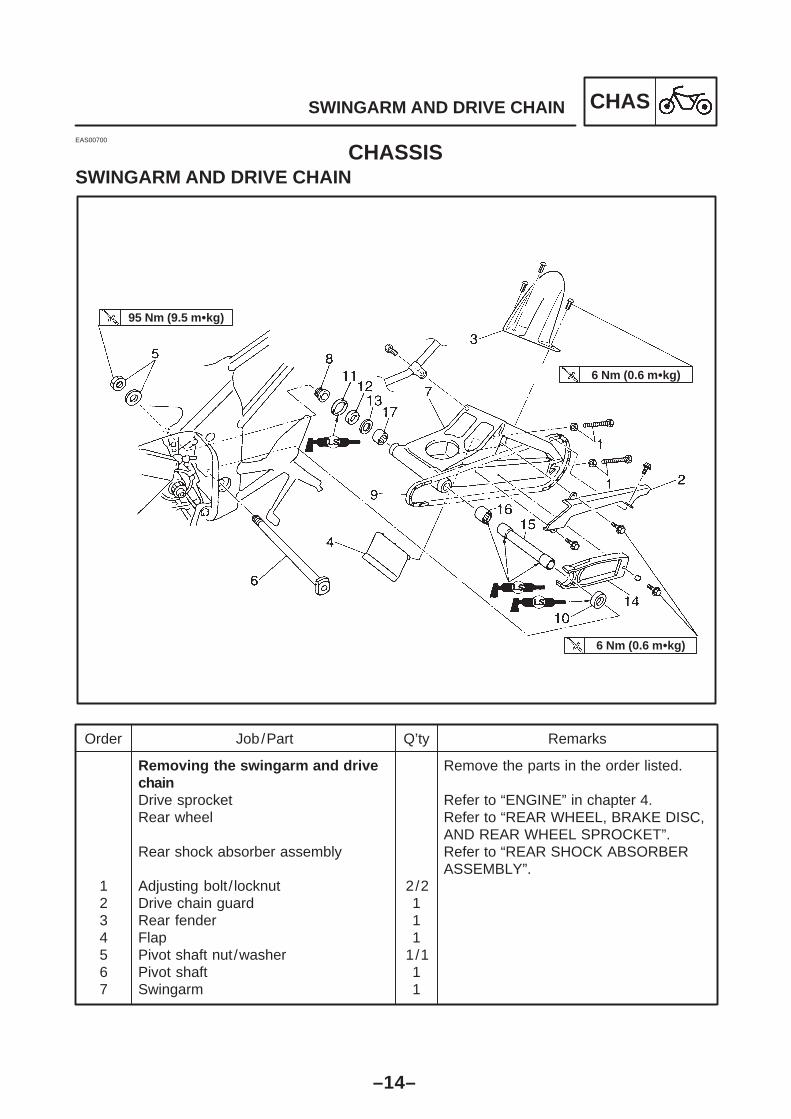
SWINGARM AND DRIVE CHAIN CHAS
Order Job/Part Q’ty Remarks
1234567
Removing the swingarm and drive chainDrive sprocketRear wheel
Rear shock absorber assembly
Adjusting bolt/ locknutDrive chain guardRear fenderFlapPivot shaft nut/washerPivot shaftSwingarm
2/2111
1/111
Remove the parts in the order listed.
Refer to “ENGINE” in chapter 4.Refer to “REAR WHEEL, BRAKE DISC,AND REAR WHEEL SPROCKET”.Refer to “REAR SHOCK ABSORBER ASSEMBLY”.
95 Nm (9.5 mkg)
6 Nm (0.6 mkg)
6 Nm (0.6 mkg)
EAS00700
CHASSISSWINGARM AND DRIVE CHAIN

–15–
SWINGARM AND DRIVE CHAIN CHAS
Order Job/Part Q’ty Remarks
8
91011121314151617
Pivot shaft adjust bolt
Drive chainDust coverOil sealBushShimDrive chain guideBushLeft bearingRight bearing
2
111111111
Refer to “REMOVING/INSTALLING THESWINGARM”.
For installation, reverse the removalprocedure.
95 Nm (9.5 mkg)
6 Nm (0.6 mkg)
6 Nm (0.6 mkg)

–16–
SWINGARM AND DRIVE CHAIN CHAS
NOTE:
EAS00709
CHECKING THE DRIVE CHAIN1. Measure: ten-link section a of the drive chainOut of specification Replace the drivechain.
Max. ten-link drive chain section150.1 mm
While measuring the ten-link section, pushdown on the drive chain to increase its tension.
Measure the length between drive chain roller1 and 11 as shown.
Perform this measurement at two or three dif-ferent places.
2. Check:drive chainStiffness Clean and lubricate or replace.
3. Clean:drive chain
a. Wipe the drive chain with a clean cloth.b. Put the drive chain in kerosine and remove
any remaining dirt.

COLOR CODEB Black. . . . . . Br Brown. . . . . Ch Chocolate. . . . Dg Dark green. . . . G Green. . . . . Gy Gray. . . . L Blue. . . . . . Lg Blue green. . . . . O Orange. . . . . P Pink. . . . . .
R Red. . . . . . Sb Sky blue. . . . . W White. . . . . Y Yellow. . . . . . B /L Black /Blue. . . . B /R Black /Red. . . . B /Y Black /Yellow. . . . Br /B Brown/Black. . . Br /L Brown/Blue. . . Br /R Brown/Red. . .
Br /W Brown/White. . . G/R Green/Red. . . G/W Green/White. . . G/Y Green/Yellow. . . . Gy /B Gray /Black. . . L /B Blue/Black. . . . L /R Blue/Red. . . . L /W Blue/White. . . L /Y Blue/Yellow. . . . O/B Orange/Black. . . .
R/B Red/Black. . . . R/G Red/Green. . . R/L Red/Blue. . . . R/W Red/White. . . R/Y Red/Yellow. . . . Sb/W Sky blue/White. . W/G White/Green. . . W/R White/Red. . . W/Y White/Yellow. . . Y /B Yellow/Black. . . .
1 Main switch2 Fuse (back up)3 Rectifier /Regulator4 AC magneto5 Battery6 Fuse (main)7 Starter relay8 Starter motor9 Starting circuit cut-off relay10 Sidestand switch11 Fuel pump12 Throttle position sensor13 Pickup coil14 CDI unit15 Ignition coil #116 Ignition coil #217 Ignition coil #318 Ignition coil #419 Spark plug20 Meter assembly21 Fuel level indicator light22 Oil level /coolant temperature
warning light23 Neutral indicator light24 Tachometer25 Combination meter26 Hi beam indicator light27 Turn signal indicator light28 Illumination light29 Speed sensor30 Neutral switch31 Thermo unit32 Fuel sender
33 Oil level switch34 Right handlebar switch35 Front brake light switch36 Light switch37 Engine stop switch38 Start switch39 Left handlebar switch40 Pass switch41 Dimmer switch42 Horn switch43 Clutch switch44 Turn signal switch45 Horn46 Flasher relay47 Headlight relay (Hi)48 Headlight relay (Lo)49 Headlight50 Auxiliary light51 Front turn signal light (left)52 Front turn signal light (right)53 Rear turn signal light (left)54 Rear turn signal light (right)55 Rear brake light switch56 Tail /brake light57 Licence light58 Fuse (ignition)59 Alarm60 Fuse (signaling system)61 Fuse (headlight)62 Fuse (radiator fan motor)63 Thermo switch64 Radiator fan motor
YZF-R6 2001 WIRING DIAGRAM (for EUR)

1 Main switch2 Fuse (back up)3 Rectifier /Regulator4 A.C. magneto5 Battery6 Fuse (main)7 Starter relay8 Starter motor9 Starting circuit cut-off relay
10 Sidestand switch11 Fuel pump12 Throttle position sensor13 Pickup coil14 CDI unit15 Ignition coil #116 Ignition coil #217 Ignition coil #318 Ignition coil #419 Spark plug20 Meter assembly21 Fuel level indicator light22 Oil level /coolant temperature warning light23 Neutral indicator light24 Tachometer25 Combination meter26 Hi beam indicator light27 Turn signal indicator light28 Meter lights29 Speed sensor30 Neutral switch31 Thermo unit32 Fuel sender33 Right handlebar switch34 Front brake light switch35 Engine stop switch36 Start switch37 Left handlebar switch38 Pass switch39 Dimmer switch40 Horn switch41 Clutch switch42 Turn signal switch43 Horn44 Flasher relay45 Frotn turn signal light (left)46 Front turn signal light (right)47 Rear turn signal light (left)48 Rear turn signal light (right)49 Oil level switch50 Headlight51 Rear brake light switch52 Tail /brake light53 Licence light54 Fuse (ignition)55 Fuse (signal)56 Fuse (headlight)57 Fuse (radiator fan motor)58 Thermo switch59 Radiator fan motor60 Headlight relay
YZF-R6 WIRING DIAGRAM (for AUS)
COLOR CODEB Black. . . . . . Br Brown. . . . . Ch Chocolate. . . . Dg Dark green. . . . G Green. . . . . Gy Gray. . . . L Blue. . . . . . Lg Blue green. . . . . O Orange. . . . . P Pink. . . . . .
R Red. . . . . . Sb Sky blue. . . . . W White. . . . . Y Yellow. . . . . . B /L Black /Blue. . . . B /R Black /Red. . . . B /W Black /White. . . B /Y Black /Yellow. . . . Br /B Brown/Black. . . Br /L Brown/Blue. . .
Br /W Brown/White. . . G/R Green/Red. . . G/W Green/White. . . G/Y Green/Yellow. . . . Gy /B Gray /Black. . . L /B Blue/Black. . . . L /R Blue/Red. . . . L /W Blue/White. . . L /Y Blue/Yellow. . . . O/B Orange/Black. . . .
R/B Red/Black. . . . R/L Red/Blue. . . . R/W Red/White. . . R/Y Red/Yellow. . . . Sb/W Sky blue/White. . W/G White/Green. . . W/R White/Red. . . W/Y White/Yellow. . . Y /B Yellow/Black. . . .