3L-P-ID - Alcon Lighting · Page Rev. 07/18/16 LED / 3L-P-ID 3L-P-ID 3L-P-ID ® ® *


FOREWORD
This supplement has been prepared to provide information covering general service repairs for the 2L-T and 3L engines mounted on the TOYOTA LAND CRUISER, HI LUX, and 4RUNNER.
Applicable models: LJ70, 72, 73, 77, 79 series LN 106, 1 1 1, 130, 135 series
For basic engine service repair, refer to the following repair manual.
2L, 3L Engine Repair Manual (Pub. No. RM123E)
Please note that the publications below have also been prepared as relevant service manuals to the components and systems in this engine.
All information contained in this manual is the most up-to-date a t the time of publication. However, specifications and proce- dures are subject to change without notice.
TOYOTA MOTOR CORPORATION

TOYOTA 2L-T, 3L ENGINE *
REPAIR MANUAL SUPPLEMENT
INTRODUCTION ENGINE MECHANICAL mi
TURBOCHARGER SYSTEM FUEL SYSTEM
COOLING SYSTEM LUBRICATION SYSTEM la
STARTING SYSTEM CHARGING SYSTEM
SERVICE SPECIFICATIONS
STANDARD BOLT TORQUE SPECIFICATIONS
SST AND SSM
0 1994 TOYOTA MOTOR CORPORATION All rights reserved. This book may not be reproduced or copied, in whole or in part, without the written permission of Toyota Motor Corporation.

INTRODUCTION Page
HOW TO USE THIS MANUAL .................................. IN-2
IDENTIFICATION INFORMATION .............................. IN-4
GENERAL REPAIR INSTRUCTIONS ........................... IN-4
ABBREVIATIONS USED IN THIS MANUAL ................. IN-7

IN-2 INTRODUCTION - How to Use This Manual
HOW TO USE THIS MANUAL To assist you in finding your way through this manual, the Sec- tion Title and major heading are given a t the top of every page.
An INDEX i s provided on the 1st page of each section to guide you to the item to be repaired.
A t the beginning of each section, PRECAUTIONS are given that pertain to all repair operations contained in that section. Read these precautions before starting any repair task,
TROUBLESHOOTING tables are included for each system to help you diagnose the problem and find the cause. The repair for each possible cause is referenced in the remedy column to quickly lead you to the solution.
REPAIR PROCEDURES
Most repair operations begin with an overview illustration. I t identifies the components and shows how the parts f i t together.
Example:
kg-cm (ft-lb, ~ . r n ) ] : Specified torque
Non-reusable part ~ ~ 2 1 1 1

INTRODUCTION - How to Use This Manual IN-3
The procedures are presented in a step-by-step format: &
a The illustration shows what to do and where to do it.
a The task heading tells what to do.
a The detailed text tells how to perform the task and gives other information such as specifications and warnings.
Example:
illustration: what to do and where
Task heading: what to do
REMOVE CRANKSHAFT PULLEY Using SST, remove the pulley.
SST 092 13-6001 7 (092 13-00060) /'.
Set part No. \
Component part No.
Detailed text: how to do task /
Install the four injection nozzles.
Torque: 650 kg-cm (47 ft-lb, 64 N-m) \ Specification
This format provides the experienced technician with a FAST TRACK to the information needed. The upper case task head- ing can be read a t a glance when necessary, and the text below it provides detailed information. Important specifications and warnings always stand out in bold type.
REFERENCES
References have been kept to a minimum. However; when they are required, you are given the page to refer to.
SPECIFICATIONS
Specifications are presented in bold type throughout the text where needed. You never have to leave the procedure to look up your specifications. They are also found in Appendix A for quick reference.
CAUTIONS, NOTICES, HINTS:
a CAUTIONS are presented in bold type, and indicate there i s a possibility of injury to you or other people.
NOTICES are also presented in bold type, and indicate the possibility of damage to the components being repaired.
HINTS are separated from the text but do not appear in bold. They provide additional information to help you efficiently perform the repair.

IN-4 INTRODUCTION - Identification Information. General Re~air Instructions
Seal Lock Adhesive IN0036
IDENTIFICATION INFORMATION ENGINE SERIAL NUMBER
The engine serial number is stamped on the left side of the cylinder block.
GENERAL REPAIR INSTRUCTIONS Use fender, seat and floor covers to keep the vehicle clean and prevent damage.
During disassembly, keep parts in order to facilitate reas- sembly.
Observe the following.
(a) Before performing electrical work, disconnect the negative (-) cable from the battery terminal.
(b) I f it is necessary to disconnect the battery for inspec- tion or repair, always disconnect the cable from the negative (-) terminal which is grounded to the vehi- cle body.
(c) To prevent damage to the battery terminal post, loos- en the terminal nut and raise the cable straight up without twisting or prying it.
(d) Clean the battery terminal posts and cable terminals with a shop rag. Do not scrape them with a file or other abrasive object.
(e) Install the cable terminal to the battery post with the nut loose, and tighten the nut after installation. Do not use a hammer to tap the terminal onto the post.
(f) Be sure the cover for the positive (+) terminal is pro- perly in place.
Check hose and wiring connectors to make sure that they are.secure and correct.
Non-reusable parts
(a) Always replace cotter pins, gaskets, O-rings, oil seals, etc. with new ones.
(b) Non-reusable parts are indicated in the component illustrations by the " 4 " symbol.
Precoated parts
Precoated parts are bolts and nuts, etc. These are coated with a seal lock adhesive a t the factory.
(a) I f a precoated part is retightened, loosened or caused to move in any way, it must be recoated with the specified adhesive.

INTRODUCTION - General Repair I nstructions IN-5
(b) Recoating of Precoated Parts c
(1) Clean off the old adhesive from the part's threads.
(2) Dry with compressed air.
(3) Apply the specified seal lock adhesive to the part's threads.
(c) Precoated parts are indicated in the component illus- trations by the " *" symbol.
7. When necessary, use a sealer on gaskets to prevent leaks.
8. Carefully observe al l specifications for bolt torques. Always use a torque wrench.
9. Use of special service tools (SST) and special service materials (SSM) may be required, depending on the nature of the repair. Be sure to use SST and SSM where specified and follow the proper work procedure. A l i s t of SST and SSM can be found at the back of this manual.
10. When replacing fuses, be sure the new fuse is the correct amperage. DO NOT exceed the rating or use one of a lower rating.
11. Care must be taken when jacking up and supporting the vehicle. Be sure to l ift and support the vehicle a t the proper locations.
(a ) I f the vehicle is to be jacked up only a t the front or rear end, be sure to block the wheels in order to en- sure safety.
(b) After the vehicle is jacked up, be sure to support it on stands. It is extremely dangerous to do any work on the vehicle raised on a jack alone, even for a small job that can be finished quickly.
12. Observe the following precautions to avoid damaging the parts:
(a) Be careful not to drop electrical components, such as sensors or relays. I f they are dropped on a hard floor, they should be replaced and not reused.
WRONG CORRECT
(b) When separating electrical connectors, pull on the connector itself, not the wires.
(c) When disconnecting vacuum hoses, pull on the end of the hose, not the middle.
IN-6 INTRODUCTION - General Re~air Instructions
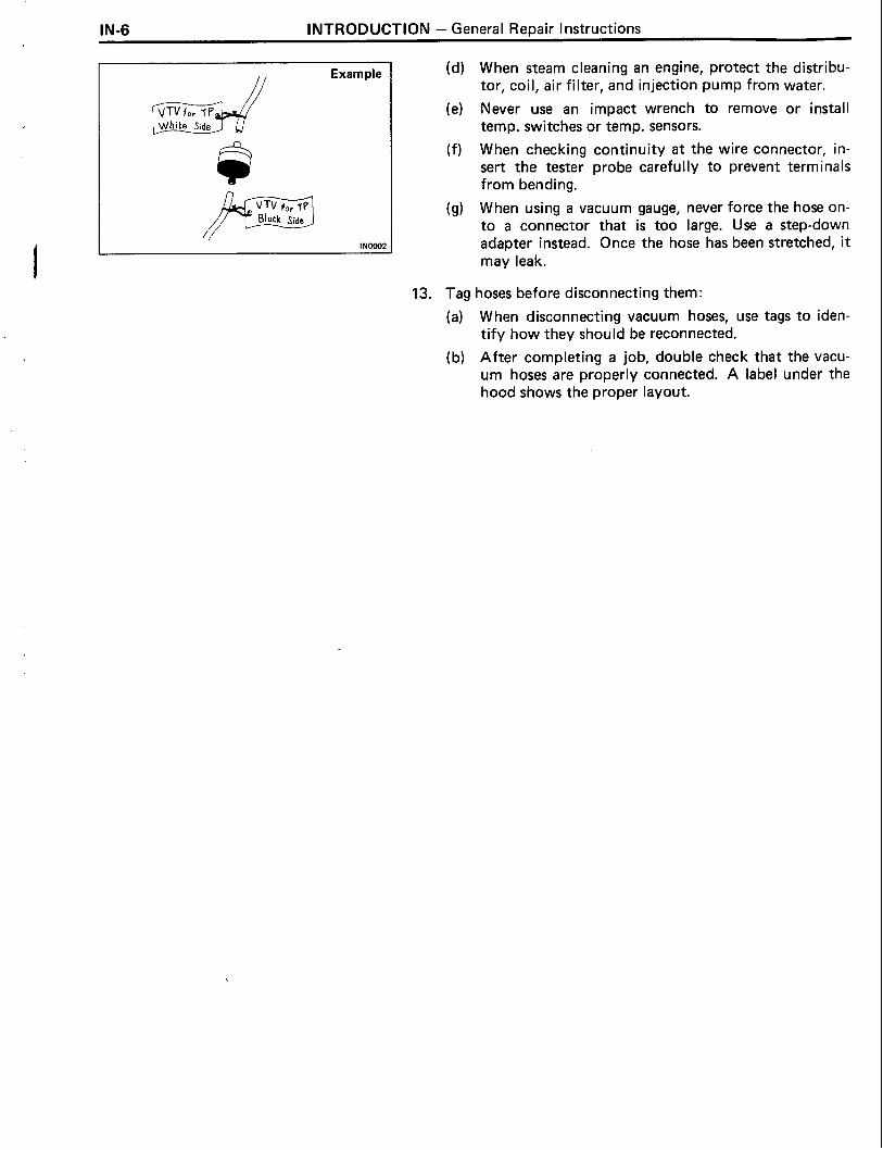
// Example (d) When steam cleaning an engine, protect the distribu-
tor, coil, air filter, and injection pump from water.
(e) Never use an impact wrench to remove or install temp. switches or temp. sensors.
(f) When checking continuity a t the wire connector, in- sert the tester probe carefully to prevent terminals from bending.
(g) When using a vacuum gauge, never force the hose on- to a connector that is too large. Use a step-down adapter instead. Once the hose has been stretched, it may leak.
13. Tag hoses before disconnecting them:
(a) When disconnecting vacuum hoses, use tags to iden- tify how they should be reconnected.
(b) After completing a job, double check that the vacu- um hoses are properly connected. A label under the hood shows the proper layout.

INTRODUCTION - Abbreviations Used in This Manual IN-7
ABBREVIATIONS USED IN THIS MANUAL, AIC Air Conditioner ACSD Automatic Cold Start Device
Approx. Approximately
EGR Exhaust Gas Recirculation
EVRV Electronic Vacuum Regulating Valve
EX Exhaust (manifold, valve)
Ex. Except
F l PG Formed in Place Gasket
F L Fusible Link
H AC High Altitude Compensation
IN Intake (manifold, valve)
LH Left-Hand
01s Oversized PI J Pilot Injection Device
RH Right-Hand
SSM Special Service Materials
SST Special Service Tools
ST D Standard
TDC Top Dead Center
U IS Undersize VSV Vacuum Switching Valve
w/ With wlo. Without

ENGINE MECHANICAL REFER TO 2L . 3L ENGINE REPAIR MANUAL (Pub . No . RM123E)
NOTE: The following pages contain only the points which differ from the above listed manual .
DESCRIPTION .................................................... TROUBLESHOOTING ...........................................
Diesel Engine Diagnosis .................................... Diesel Electrical System Diagnosis
[2L-T Austria] .............................................. Diesel Electrical System Diagnosis
[2L-T Others] ............................................... ENGINE.TUNE4.JP ...............................................
............. INTAKE VENTURI SYSTEM (LN 2L-T only)
COMPRESSION CHECK ....................................... ....................................... CYLINDER HEAD (2L-T)
CYLINDER BLOCK ...............................................
Page
EM-2
EM-4
EM-4
EM-1 3
EM-1 6
EM-18
EM-30
EM-33
EM-35
EM-46

EM-2 ENGINE MECHANICAL - Description
DESCRIPTION The 2L-T engine is an in-line 4-cylinder 2.4 liter OHC engine.
The 3L engine is an in-line 4-cylinder 2.8 liter OHC engine.
2 L-T
ENGINE MECHANICAL - Description EM-3
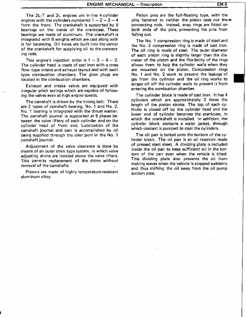
The 2L-T and 3L engines are in-line 4-cylinder engines with the cylinders numbered 1 - 2 - 3 - 4 from the front. The crankshaft is supported by 5 bearings on the inside of the crankcase. These bearings are made of aluminum. The crankshaft is integrated with 8 weights which are cast along with it for balancing. Oil holes are built into the center of the crankshaft for supplying oil to the connect- ing rods.
This engine's injection order is 1 - 3 - 4 - 2. The cylinder head is made of cast iron with a cross flow type intake and exhaust layout and with swirl type combustion chambers. The glow plugs are located in the combustion chambers.
Exhaust and intake valves are equipped with . irregular pitch springs which are capable of follow-
ing the valves even at high engine speeds.
The camshaft is driven by the timing belt. There are 2 types of camshaft bearing, No. 1 and No. 2. No. 1 bearing i s integrated with the thrust washer. The camshaft journal i s supported at 5 places be- tween the valve lifters of each cylinder and on the cylinder head of front end. Lubrication of the camshaft journal and cam is accomplished by oil being supplied through the oiler port in the No. 1 camshaft journal.
Adjustment of the valve clearance is done by means of an outer shim type system, in which valve adjusting shims are located above the valve lifters. This permits replacement of the shims without removal of the camshafts.
Pistons are made of highly temperature-resistant aluminum alloy.
Piston pins are the full-floating type, with the pins fastened to neither the piston boss nor the* connecting rods. Instead, snap rings are fitted on both ends of the pins, preventing the pins from falling out.
The No. 1 compression ring is made of steel and the No. 2 compression ring is made of cast iron. The oil ring is made of steel. The outer diameter of each piston ring i s slightly larger than the dia- meter of the piston and the flexibility of the rings allows them to hug the cylinder walls when they are mounted on the piston. Compression rings No. 1 and No. 2 work to prevent the leakage of gas from the cylinder and the oil ring works to scrape oil off the cylinder walls to prevent it from entering the combustion chamber.
The cylinder block is made of cast iron. It has 4 cylinders which are approximately 2 times the length of the piston stroke. The top of each cy- linder is closed off by the cylinder head and the lower end of cylinder becomes the crankcase, in which the crankshaft is installed. In addition, the cylinder block contains a water jacket, through which coolant is pumped to cool the cylinders.
The oil pan is bolted onto the bottom of the cy- linder block. The oil pan is an oil reservoir made of pressed steel sheet. A dividing plate is included inside the oil pan to keep sufficient oil in the bot- tom of the pan even when the vehicle is tilted. This dividing plate also prevents the oil from making waves when the vehicle is stopped suddenly and thus shifting the oil away from the oil pump suction pipe.

GENERAL
1. Diesel engine problems are usually caused by the engine or fuel system. The injection pump is very rarely the cause of fuel system problems.
2. Before beginning fuel system tests, first check that the engine compression, valve timing and other major systems are within specifications.
' I PRELIMINARY CHECKS
Before performing fuel system checks, ensure that the engine is in good running condition. I f neces- sary, first check the compression, timing and major components or systems.
Check the air filter, and clean or replace it if necessary.
Check that there is sufficient fuel in the tank.
Check i f the fuel is contaminated with gasoline or other foreign elements. Only good-quality diesel fuel should be used.
Bleed air from the system by pumping the priming.
Check for water in the fuel filter and fuel tank, and drain as necessary.
I f the engine will not crank or i f it cranks slowly, first troubleshoot the electrical system.
EM-4 ENGINE MECHANICAL - Troubleshooting (Diesel Engine Diagnosis)
TROUBLESHOOTING Diesel Engine Diagnosis

ENGINE MECHANICAL - Troubleshooting (Diesel Engine Diagnosis) EM-5
PRECAUTION: &
1. The basic troubleshooting procedures for the diesel engine (valve clearance, compression, bearings, valves, pistons, etc.) are the same checks you would make for gasoline engine.
2. Repair of the injection pump requires considerable skill and use of a special test bench.
ENGINE WILL NOT CRANK
(Possible Cause) (Check Procedure and Correction Method)
1. LOOSE OR CORRODED BATTERY CABLES
I
Check cables from battery to starter and make nec- essary repairs.
- 1 2. DISCHARGED BAT-
ENGINE CRANKS SLOWLY-WILL NOT START
Check alternator output and drive belt.
I f necessary, repair. (See page CH-3)
3. INOPERATIVE STARTER 1
HINT: Minimum cranking speed: Cold 100 rpm Hot 150rpm
Check for battery voltage a t starter terminals 30 and 50. I f okay, see STARTING SYSTEM for repair pro- cedure. ,
(Possible Cause) (Check Procedure and Correction Method)
Check alternator output and drive belt.
I f necessary, repair. (See page CH-3)
1. LOOSE OR CORRODED BATTERY CABLES
Check cables from battery to starter and make nec- essary repairs.
7 3. IMPROPER ENGINE OIL i Check engine oil.
I f improper viscosity, drain and refill with oil of vis- cosity recommended by manufacturer. (See page LU-4)

EM-6 ENGINE MECHANICAL - Troubleshooting (Diesel Engine Diagnosis)
-
ENGINE CRANKS NORMALLY BUT WILL NOT START
(Possible Cause) (Check Procedure and Correction Method)
Loosen any one injection pipe union nut from i ts nozzle holder.
2. NO FUEL CUT SOLENOID I OPERATION
Crank engine for about 5 seconds while confirming that fuel is being discharged from pipe.
I f fuel is coming out, begin diagnosis from item 4.
I f not, begin from item 2.
With starter switch turned ON, check for fuel cut solenoid operation noise (clicking sound) while re- peatedly connecting and disconnecting fuel cut solenoid.
I f no noise, check i f there is battery voltage to sole- noid when starter switch is ON.
I f battery voltage is confirmed, fuel cut solenoid is faulty and should be replaced. I f no voltage, refer to E LECTRICAL DIAGNOSIS and make necessary repairs.
Disconnect inlet hoses from fuel filter, and feed clean fuel from separate container directly into fuel pump. HINT: When feeding fuel tank directly into pump, keep container a t same level as vehicle fuel tank.
I f engine starts, either fuel filter or line between fuel tank and filter is clogged and should be repaired accordingly.
I f engine s t i l l does not start (no fuel intake), check fuel line between filter and pump,
I f normal, pump is faulty and should be replaced.
5. INOPERATIVE PRE-HEATING I OPERATION
4. FUEL LEAKAGE FROM INJECTION PIPES
With starter switch turned ON and glow plug indi- cator light illuminated, check that there is voltage applied to glow plug.
I f not, refer to ELECTRICAL DIAGNOSIS and re- pair as necessary.
Check for loose unions or cracks.
I f leaking, tighten to standard torque or, i f necessary, replace pipe(s).

ENGINE MECHANICAL - Troubleshooting (Diesel Engine Diagnosis) EM-7
6. FAULTY GLOW PLUG I OPERATION Check glow plug for continuity.
I f no continuity, a broken wire is indicated and glow I plug should be replaced. I
1 7. IMPROPER INJECTION TIMING b Check injection timing. (See page EM-24 or 25)
Plunger stroke: - 2L-T (Austria) Within the marks of belt case
and pump flange. (See page EM-24)
2L-T (Others) 0.54 - 0.66 mm (0.0213 - 0.0260 in.)
3L 0.84 - 0.96 mm (0.0331 - 0.0378 in.)
I f not as above, injection pump is improperly adjusted.
Check injection pressure with a nozzle tester.
Opening pressure: 145 - 155 kg/cm2 (2,062 - 2,205 psi) (14,220 - 15,200 kPa)
I f not as above, nozzle adjustment is improper and pressure should be readjusted. I f pressure cannot be adjusted to specification, replace injection nozzle.
8. (2L-T) IMPROPER COLD START ADVANCE AND FAST IDLE
Check timer piston stroke and fast idle lever opening angle with an injection pump tester when cold start advance is operated.

EM-8 ENGINE MECHANICAL - Troubleshooting (Diesel Engine ~iagnosis)
ROUGH IDLE WITH WARM ENGINE
(Possible Cause) (Check Procedure and Correction Method)
1. IMPROPER ADJUSTMENT OF ACCELERATOR CABLE
I
5. IMPROPER OPERATION OF INJECTION NOZZLES OR DELIVERY VALVES
With accelerator pedal released, check that adjusting lever is in contact with idle speed adjusting screw. Also check if accelerator cable or linkage is catching on something.
I f necessary, adjust so that lever is in contact with screw, or make other required repairs.
3. FUEL LEAKAGE
Refer to step 7 of ENGINE CRANKS NORMALLY BUT WILL NOT START, above. I
- I
2. IDLE SPEED Check idle speed. (See page EM-27)
Idle speed: 2L-T 700 - 800 rpm 3L 650 - 750 rpm
HINT: I f less than standard, idling would normally be rough.
I f not as above, adjust with idle speed adjusting screw.
Check for leaks a t injection pump connections, pump distributive head bolt, injection nozzles and delivery valve holders. Tighten any loose connections to specified torque or replace parts as necessary.
With engine idling, loosen injection pipe to each cylinder in order, and check i f idle speed changes.
I f no change, a faulty cylinder is indicated. Check according to following procedure.
Faulty injection nozzle
Check injection nozzle with a nozzle tester.
Opening pressure: 145 - 155 kg/cm2 (2,062 - 2,205 psi) (14,220 - 15,200 kPa)
I f not as above, nozzle adjustment is improper and pressure should be readjusted.
I f pressure cannot be adjusted to specification, re- place injection nozzle.
Faulty delivery valve
I f injection pressure is as specified, delivery valve is defective and should be replaced.

ENGINE MECHANICAL - Troubleshootina (Diesel Ennine Diagnosis) EM-9
)r
ENGINE SUDDENLY STOPS
(Possible Cause) (Check Procedure and Correction Method)
Check to see i f engine re-starts according to pre- scribed procedure.
I f not, refer to ENGINE CRANKS NORMALLY BUT W I LL NOT START, above, and repair as necessary.
Refer to ROUGH IDLE WITH WARM ENGINE and repair accordingly.
3. MALFUNCTION OF FUEL CUT SOLENOID WILL NOT START, above, and check accordingly.
HINT: No operation noise from fuel cut solenoid may be due to loose electrical connections, so check connectors before proceeding with further repairs.
LACK OF POWER
4. NO FUEL INTO INJECTION PUMP
HINT: First check that the air cleaner is not clogged & the engine overheating.
Not applicable i f the customer desires an output power higher than specified for that vehicle. For ac- curacy, adjust with a chassis dynamo.
Refer to step 3 of ENGINE CRANKS NORMALLY BUT WILL NOT START, above.
(Possible Cause) (Check Procedure and Correction Method)
I f necessary, adjust so that lever is in contact with screw, or make other required repairs.
1. IMPROPER ADJUSTMENT OF ACCELERATOR CABLE
2. INSUFFICIENT MAXIMUM SPEED
With accelerator fully depressed, check that adjusting lever is in contact with maximum speed adjusting screw. Also check i f accelerator cable or linkage is catching on something.
Check maximum,speed. (See page EM-27)
Maximum speed: 2 L-T 4,700 - 4,900 rpm 3L (Hong Kong, Singapore and Malaysia)
4,300 - 4,500 rpm 3L (Others) 4,500 - 4,700 rpm
If not as above, adjust with maximum speed adjust- ing screw.

EM-10 ENGINE MECHANICAL - Troubleshootinn (Diesel Engine Diaanosis)
1 5. CLOGGED FUEL FILTER
3. INTERCHANGED OVERFLOW SCREW (OUT) AND INLET (NO MARK) FITTING
Disconnect inlet hose to fuel filter, and feed clean fuel directly into pump.
HINT: When feeding fuel directly into pump, keep container at same level as vehicle fuel tank.
I f engine condition improves, fuel filter is clogged and should be replaced. I f no increase in engine condition after replacing fuel filter, check priming pump (hand pump) or perform other necessary repairs.
HINT: Overflow screw is marked "OUT" and has an inner jet. Although both fittings are same size, they must not be interchanged.
Refer to step 3 of ROUGH IDLE WITH WARM ENGINE.
16. IMPROPER INJECTION TIMING I
EXCESSIVE EXHAUST SMOKE
Refer to step 7 of ENGINE CRANKS NORMALLY BUT WILL NOT START.
7. FAULTY INJEC
HINT: Check that the air cleaner is not clogged.
Refer to step 9 of ENGINE CRANKS NORMALLY BUT WILL NOT START.
Check with the customer whether or not oil consumption has been excessive.
(Possible Cause) (Check Procedure and Correction Method)
I 1. IMPROPER IN-I
1 2. CLOGGED FUEL FILTER I
Refer to step 7 of ENGINE CRANKS NORMALLY BUT WILL NOT START.
HINT: Black smoke indicates advanced timing while white smoke indicates retarded timing. Adjustments should be made accordingly.
Refer to step 5 of LACK OF POWER.
HINT: A t high speed (2,000 - 3,000 rpm), a clogged filter tends to make exhaust smoke white.
HINT: Excessive exhaust smoke is often caused by

ENGINE MECHANICAL - Troubleshooting (Diesel Engine Diagnosis) EM-11
EXCESSIVE FUEL CONSUMPTION
HINT: Check whether clutch slipping, brakes grabbing, tires wrong size or air filter clogged.
(Possible Cause) (Check Procedure and Correction Method)
Refer to step 3 of ROUGH l DLE WITH WARM ENGINE.
1 3. MAXIMUM SPEED TOO HIGH 1-
After sufficiently warming up engine, check idle speed. (See page EM-27)
Idle speed: 2L-T 700 - 800 rpm 3L 650 - 750 rpm
If not as above, adjust with idle speed adjusting screw.
Check maximum speed. (See page EM-27)
Maximum speed: 2 L-T 4,700 - 4,900 rpm 3L (Hong Kong, Singapore and Malaysia)
4,300 - 4,500 rpm 3L (Others) 4,500 - 4,700 rpm
If not as above, adjust bivith maximum speed adjust- ing screw.
Refer to step 9 of ENGINE CRANKS NORMALLY BUT WILL NOT START.
4. IMPROPER INJECTION TIMING 1 Refer to step 7 of ENGINE CRANKS NORMALLY BUT WILL NOT START.
EM-12 ENGINE MECHANICAL - Troubleshooting (Diesel Engine Diagnosis)
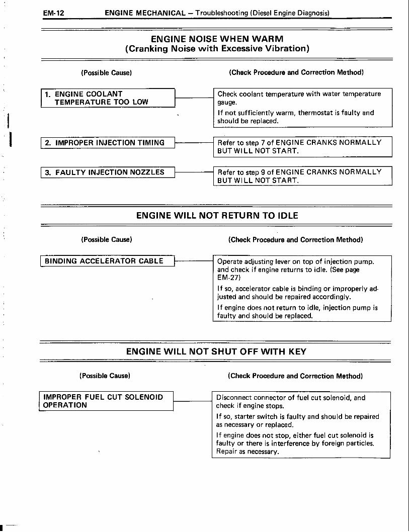
ENGINE NOISE WHEN WARM (Cranking Noise with Excessive Vibration)
(Possible Cause) (Check Procedure and Correction Method)
1. ENGINE COOLANT TEMPERATURE TOO LOW
Check coolant temperature with water temperature gauge.
I f not sufficiently warm, thermostat is faulty and should be replaced.
2. IMPROPER IN
ENGINE WlLL NOT RETURN TO IDLE
Refer to step 7 of ENGINE CRANKS NORMALLY BUT WI LL NOT START.
3. FAULTY INJ
(Possible Cause) (Check Procedure and Correction Method)
Refer to step 9 of ENGINE CRANKS NORMALLY BUT WILL NOT START.
Operate adjusting lever on top of injection pump. and check i f engine returns to idle. (See page E M-27)
I f so, accelerator cable is binding or improperly ad- justed and should be repaired accordingly.
I f engine does not return to idle, injection pump is faulty and should be replaced.
ENGINE WlLL NOT SHUT OFF WITH KEY
(Possible Cause) (Check Procedure and Correction Method)
IMPROPER FUEL CUT SOLENOID OPERATION
Disconnect connector of fuel cut solenoid, and check i f engine stops.
I f so, starter switch is faulty and should be repaired as necessary or replaced.
I f engine does not stop, either fuel cut solenoid is faulty or there is interference by foreign particles. Repair as necessary.

I roub1esnootlng ENGINE MECHANICAL -(Diesel Electrical System Diagnosis [2L-T Austria]) EM-13
Diesel Electrical System Diagnosis [2L-T Austria1 + ENGINE DOES NOT START COLD
HINT: Battery voltage a t least 12 V - starter switch OFF.
Engine cranks normally.
Fusible link okay. Check the voltage marked with an asterisk (* ) just as the starter switch is placed a t ON because the voltage will change.
1. Pre-Heating System (Super Glow Type)
I isc connect the water temperature I sensor.
No I (See page ST-2) I Fuse I and repair if necessary. I I
I I I I Blown 1 Fuse OK
Check i f indicator light lights up with starter switch ON. Light on: 5 - 6 seconds
Yes
Check f u v A Check for short circuit I
I Starter switch OFF. I CONTINUED ON PAGE EM-14
Check for battery voltage to terminal 825 ( W) or A4 (LN) of pre-heating timer connector (on wire harness side).
Check indicator light bulb.
Check for battery voltage to terminal A6 ( W ) or A3 (LN) of pre-heating timer connector (on wire harness side).
-1 Replace bulb. Bulb
1 Yes
No Good 1 Bulb OK
Are terminals 81 5, 822 and B24(LJ) or B11 and B14(LN) of the timer grounded?
Replace timer. Open circuit or ground faulty in wire harness between terminals of the timer and body ground. ---
Pre-Heating Timer (Emission Control ECU)

Troubleshooting EM-14 ENGINE MECHANICAL - (Diesel Electrical System Diagnosis [2L-T Austria])
CONTINUED FROM PAGE EM-13
1
Timer is faulty and should be replaced. No 1
"Place starter switch a t ON and check i f current flow to terminal B23( W ) or A5(LN) of timer is in accordance. Current flow: 120 seconds
I * ~ f t e r completion of pre-heating, I
Pre-heating duration differs from the specified duration.
Voltage
I 1 Starter switch OFF. 1
check for voltage a t terminal B23 ( LJ) or A5 ( LN) again when starter switch i s placed a t START. No
Voltage
"Place starter switch a t ON and check for voltage to glow plug a few seconds later. Thereafter, voltage should drop about 112.
- Voltage Remains
t I Glow plug okay.
No Voltage
"Check for battery voltage to positive (+I side of glow plug resistor. I f okay, replace the resistor. I f no voltage, No. 2 glow plug relay is faulty and should be replaced.
i
Connect water temperature sensor.
"Check for battery voltage a t negative (-1 side of glow plug resistor. I f no voltage, No. 1 glow plug relay is faulty and should be replaced.
a t Battery Voltage, or Falls to 0 v
Check glow plug for resistance. -4 Glow plug i s faulty and should be replaced. Infinity

m==--
Troubleshooting ENGINE MECHANICAL - (Diesel Electrical System Diagnosis [2L-T Austria]) EM-15
2. Fuel Cut Solenoid Valve a
With starter switch turned ON, check for fuel cut solenoid valve operation noise (clicking sound) while repeatedly connecting and disconnecting fuel cut solenoid valve.
No Noise
i
1 Fuel cut solenoid valve okay. Noise
I
Check fuse. Check for short circuit, and repair as necessary. I
Fuse OK Blown
I No Noise
I ---
I I Replace fuel cut solenoid valve.
Apply battery voltage directly to solenoid, and check for noise.
Check wire harness from fuse to fuel cut solenoid. Noise

Troubleshootins EM-16 ENGINE MECHANICAL - (Diesel ~lectrical System Diagnosis I2L-T Others])
Diesel Electrical System Diagnosis [2L-T Others] ENGINE DOES NOT START COLD
HINT: Battery voltage at least 12 V - starter switch OFF.
Engine cranks normally.
Fusible link okay.
Check the voltage marked with an asterisk ( * ) just as the starter switch is placed at ON because the voltage will change.
1. Pre-Heating System (Super Glow Type)
I Disconnect the water temperature / sensor.
1 Yes
t P
Check for short circuit and repair i f necessary.
Check i f indicator light lights up with starter switch ON. Light on: 6 - 7 seconds
Check indicator Replace bulb.
No Good
I I Bulb OK
- No
Blown
P
Check fuse. (See page ST-2)
i Starter switch OFF
timer connector (on wire harness side). I f okay, pre-heating timer is faulty and should be replaced.
I after engine is started.
I
Fuse
t
I f faulty, repair charging system as necessary. i I f okay, timer is faulty and should be replaced.
"Check that there is 1 V or less to terminal 9. I f okay, timer is faulty and should be replaced. I
"Check for battery voltage to terminal 1 of pre-heating timer
Starter switch OFF.
- No
Start engine and check i f there is voltage at terminal , 9 of pre-heating timer. i
"Check if voltage to terminal 1 of pre-heating timer is terminated
I CONTINUED ON PAGE EM-17
with starter switch ON.
- No
Pre-Heating Timer
6 5 4 3 1
Voltage

Troubleshooting ENGINE MECHANICAL - (Diesel Electrical System Diagnosis [2L-T Others] ) EM- 17
1 CONTINUED FROM PAGE EM-16
I "Place starter switch a t ON and 1- check i f current flow to terminal 5 of timer is in accordance. Current flow : 15-29 seconds
I I Pre-heating duration differs from the specified I duration.
I Timer is faulty and should be replaced.
Voltage
"After completion of pre-heating, check for voltage a t terminal 5 again when starter switch is
Voltage
I
( Starter switch OFF.
"Check for battery voltage a t negative (-) side of glow plug resistor. I f no voltage, No.1 glow plug relay is faulty and should be replaced.
/*place starter switch a t ON and 1
a t All
check for voltage to glow plug a few seconds later. Thereafter, voltage should drop about 112.
'Check for battery voltage to positive (+) side of glow plug resistor. I f okay, replace the resistor. I f no voltage, No.2 glow plug relay is faulty and should be replaced.
- No
I
Voltage Remains a t Battery Voltage, of Falls to 0 v
Voltage -
-
Glow plug is faulty and should be replaced.
I Glow plug okay. I
I Connect water temperature sensor. I

EM-18 ENGINE MECHANICAL - Engine Tune-up
ENGINE TUNE-UP INSPECTION OF ENGINE COOLANT (See steps 1 and 2 on page CO-4)
INSPECTION OF ENGINE OIL (See steps 1 and 2 on page LU-4)
INSPECTION OF BATTERY (See pages 1 and 2 on page CH-3)
Standard specific gravity: When fully charged at 20°C (68" F)
1.27 - 1.29 (80D26R) 1.25 - 1.27 (Others)
INSPECTION OF AIR FILTER (Paper Filter Type)
1. INSPECT AIR FILTER
Visually check that the filter element is not excessively dirty, damaged or oily.
2. CLEAN AIR FILTER
Clean the filter element with compressed air.
First blow from the inside thoroughly. Then blow off the outside of the filter element.
(Washable Type)
1. INSPECT AIR FILTER
Visually check that the filter element is not excessively dirty, damaged or oily.
/ 1 2. CLEAN AIR FILTER

ENGINE MECHANICAL - Engine Tune-up EM-19
(b) Submerge the filter element in the water and agitate 3
it up and down more than ten times.
(c) Repeat rinsing in clean water until rinse water is clear.
(d) Remove excess water by shaking the filter element or blowing with compressed air.
NOTICE: Do not beat or drop filter element.
(e) Wipe off dust on the air cleaner case interior.
INSPECTION OF ALTERNATOR DRIVE BELTS (See step 3 on page CH-3)
Drive belt deflection: New belt 7 - 10 mm (0.28 - 0.39 in.) Used belt 10 - 15 mm (0.39 - 0.59 in.)
Drive belt tension (Reference) : New belt 40 - 6 0 kg Used belt 20 - 35 kg
INSPECTION OF GLOW PLUGS (See page ST-6)

EM-20 ENGINE MECHANICAL - Engine Tune-up
ADJUSTMENT OF VALVE CLEARANCE
HINT: Adjust the valve clearance while the engine is cold.
No. 1 No. 3 EX EX
No. 2 No. 4 EX EX
(2 L-T) REMOVE AIR CLEANER
(w/ Intake Pipe) REMOVE INTAKE PIPE
REMOVE CYLINDER HEAD COVER (See step 16 on page EM-38)
SET NO. 1 CYLINDER TO TDCICOMPRESSION
(a) Turn the crankshaft pulley clockwise, and align its groove with the timing pointer.
(b) Check that the valve lifters on the No. 1 cylinder are loose and valve lifters on the No. 4 cylinder are tight.
I f not, turn the crankshaft one revolution (360") and align the mark as above.
ADJUST VALVE CLEARANCE
(a) Check only the valves indicated in the illustration.
Using a feeler gauge, measure the clearance be- tween the valve lifter and camshaft.
Record the valve clearance measurements which are out of specification. They will be used later to determine the required replacement adjusting shim.
Valve clearance (Cold) : Intake 0.20 - 0.30 mm (0.008 - 0.012 in.) Exhaust 0.40 - 0.50 mm (0.016 - 0.020 in.)
(b) Turn the crankshaft one revolution (360°), and align the mark as above (See procedure step 4).
(c) Check only the valves indicated in the illustration. Measure the valve clearance. (See procedure step (a))
(d) Remove the adjusting shim.
Turn the crankshaft to position the cam lobe of the camshaft on the adjusting valve upward. Using SST, press down the valve lifter.
SST 09248-6401 0
HINT: Before pressing down the valve lifter, position the notch on the exhaust manifold side.

ENGINE MECHANICAL - Engine Tune-up EM-2 1
Remove the adjusting shim with small screwdriver * and magnetic finger.
(e) Determine the replacement adjusting shim size by using following the formula or charts:
0 Using a micrometer, measure the thickness of the shim which was removed.
Calculate the thickness of the new shim so the valve clearance comes within specified value.
. . . . . . T Thickness of used shim
. . . . . . A Measured valve clearance N . . . . . . Thickness of new shim
Intake side: N = T + (A - 0.25 mm (0.010 in.)) Exhaust side: N = T + (A - 0.45 mm (0.018 in.))
Select a new shim with a thickness as close as pos- sible to the calculated values.
HINT: Shims are available in seventeen sizes in incre- ments of 0.050 mm (0.0020 in.), from 2.500 mm (0.0984 in.) to 3.300 mm (0.1 299 in.).
( f) Install a new adjusting shim.
Place a new adjusting shim on the valve lifter.
RemoveSST.
SST 09248-6401 0
(g) Recheck the valve clearance.
6. REINSTALL CYLINDER HEAD COVER (See step 4 on page EM-43)
7. (wl Intake Pipe) REINSTALL INTAKE PIPE
8. (2L-T) REINSTALL AIR CLEANER

EM-22 ENGINE MECHANICAL - Engine Tune-up
Adjusting Shim Selection Using Chart
INTAKE
New shim thickness rnrn (in.)
Shim Shim I No. / Thickness 1 1 Thickness I
Intake valve clearance (Cold) : 0.20 - 0.30 mm (0.008 - 0.012 in.)
EXAMPLE: The 2.80.0 rnrn (0.1 102 in.) shim i s installed and the measured clearance is 0.350 rnrn (0.0138 in.). Replace the 2.800 rnrn (0.1102 in.) shim with a No. 21 shim.

ENGINE MECHANICAL - Engine Tune-up EM-23
Adjusting Shim Selection Using Chart
EXHAUST
Exhaust valve clearance: 0.40 - 0.50 rnm (0.016 - 0.020 in.)
EXAMPLE: The 2.800 mm (0.1 102 in.) shim i s installed and the measured clearance is 0.350 mm (0.0138 in.). Replace the 2.800 mm (0.1 102 in.) shim with a No. 11 shim.

EM-24 ENGINE MECHANICAL - Encline Tune-up
Flange R1167
INSPECTION AND ADJUSTMENT OF INJECTION TIMING (2L-T Austria)
CHECK INJECTION TIMING
Using a mirror, check that the mark on the belt case and the center mark on the pump flange are correctly aligned with the amount of overlap as shown.
ADJUST INJECTION TIMING
(a) Loosen the following bolts and nuts:
(1) Two bolts holding injection pump to injection pump stay.
(2) Two nuts holding injection pump to timing belt case.
HINT: Do not loosen the union nuts of injection pump more than 114 of a turn.
(b) Slightly tilt the injection pump body and align the belt case mark with the center mark on the pump flange to the correct overlap dimension.
(c) Tighten the following bolts and nuts:
(1) Two nuts holding injection pump to timing belt case.
Torque: 210 kg-cm (15 ft-lb, 21 N-m)
(2) Two bolts holding injection pump to injection pump stay.
Torque: 185 kg-cm (13 ft-lb, 18 N-m)
START ENGINE AND CHECK FOR LEAKS
ENGINE MECHANICAL - Engine Tune-up EM-25
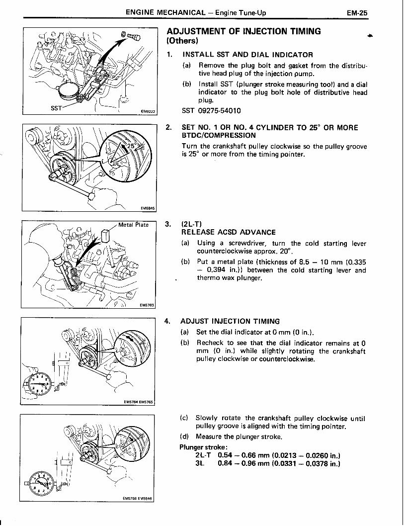
ADJUSTMENT OF INJECTION TIMING (Others)
1. INSTALL SST AND DIAL INDICATOR
(a) Remove the plug bolt and gasket from the distribu- tive head plug of the injection pump.
(b) Install SST (plunger stroke measuring tool) and a dial indicator to the plug bolt hole of distributive head plug.
SST 09275-5401 0
SET NO. 1 OR NO. 4 CYLINDER TO 25" OR MORE BTDCICOMPRESSION Turn the crankshaft pulley clockwise so the pulley groove is 25" or more from the timing pointer.
(2 L-T) RELEASE ACSD ADVANCE (a) Using a screwdriver, turn the cold starting lever
counterclockwise approx. 20".
(b) Put a metal plate (thickness of 8.5 - 10 mm (0.335 - 0.394 in.)) between the cold starting lever and thermo wax plunger.
ADJUST INJECTION TIMING
(a) Set the dial indicator a t 0 mm (0 in.).
(b) Recheck to see that the dial indicator remains a t 0 mm (0 in.) while slightly rotating the crankshaft pulley clockwise or counterclockwise.
(c) Slowly rotate the crankshaft pulley clockwise until pulley groove is aligned with the timing pointer.
(d) Measure the plunger stroke.
Plunger stroke: 2L-T 0.54 - 0.66 mm (0.0213 - 0.0260 in.) 3L 0.84 - 0.96 mm (0.0331 - 0.0378 in.)

EM-26 ENGINE MECHANICAL - Engine Tune-up
(e l Loosen the following bolts and nuts:
(1) Four union nuts of injection pipes a t injection pump side.
(2) Two bolts holding injection pump to injection pump stay.
(3) Two nuts holding injection pump to timing belt case.
HINT: Do not loosen the union nuts of injection pump more than 114 of a turn.
(f) Adjust plunger stroke by slightly tilting the injection pump body.
If the stroke is less than specified, tilt the pump toward the engine.
I f the stroke i s greater than specified, tilt the pump away from the engine.
(g) Tighten the following bolts and nuts:
(1) Two nuts holding injection pump to timing belt case.
Torque: 210 kg-cm (15 ft-lb, 21 N-m)
8 Recheck the plunger stroke.
(2) Two bolts holding injection pump to injection pump stay.
Torque: 185 kg-cm (13 ft-lb, 18 N-m)
(3) Four union nuts of injection pipes.
Torque: 250 kg-cm (18 ft-lb, 25 N-m)
(2 L-T) REMOVE METAL PLATE
REMOVE SST AND DIAL INDICATOR
(a) Remove SST and the dial indicator.
SST 09275-5401 0
(b) Install a new gasket and the plug bolt of the distribu- tive head plug.
Torque: 170 kg-cm (12 ft-lb, 17 N-m)
START ENGINE AND CHECK FOR LEAKS

ENGl NE MECHANICAL - Engine T u n e U ~ EM-27
ADJUSTMENT OF IDLE SPEED AND MAXIMUM * SPEED
1. INITIAL CONDITIONS
(a) Engine a t normal operating temperature
(b) Air cleaner installed
(c) All accessories switched OFF
(d) All vacuum lines properly connected
(e) Valve clearance set correctly
(f) Injection timing set correctly
(g) Transmission in neutral range
2. CONNECT TACHOMETER
3. ADJUST IDLE SPEED
(a) Check that the adjusting lever touches the idle speed adjusting screw when the accelerator pedal is released.
f not, adjust the accelerator linkage.
b) Start the engine.
(c) Check the idle speed.
Idle speed: 2L-T 700 - 800 rpm 3L 650 - 750 rpm
(d) Adjust the idle speed.
Disconnect the accelerator linkage.
Loosen the lock nut of the idle speed adjusting screw.
Adjust the idle speed by turning the IDLE SPEED ADJUSTING SCREW.
Idle speed : 2 L-T 750 rpm 3L 700 rpm
Securely tighten the lock nut, and recheck the idle speed.
Reconnect the accelerator linkage.
After adjustment, adjust the accelerator linkage.
4. ADJUST MAXIMUM SPEED
(a) Check that the adjusting lever touches the maximum speed adjusting screw when the accelerator pedal i s depressed all the way.
I f not, adjust the accelerator linkage.
(b) Start the engine.
(c) Depress the accelerator pedal all the way.

EM-28 ENGINE MECHANICAL - Engine Tune-up
(d) Check the maximum speed.
Maximum speed: 2 L-T 4,700 - 4,900 rpm 3L (Hong Kong, Singapore and Malaysia)
4,300 - 4,500 rprn 3L (Others) 4,500 - 4,700 rprn
(e) Adjust the maximum speed.
Disconnect the accelerator linkage. Cut out the seal wire of the maximum speed ad- justing screw.
(2L-T and w/ HAC) Using SST, loosen the lock nut of the maximum speed adjusting screw.
SST 09275-54020
(W/O HAC) Loosen the lock nut of the maximum speed adjust- ing screw.
Adjust the maximum speed by turning the MAXI- MUM SPEED ADJUSTING SCREW.
Maximum speed: 2 L-T 4,800 rpm 3L (Hong Kong, Singapore and Malaysia)
4,400 rprn 3L (Others) 4,600 rprn
HINT: Adjust a t idle speed. Then, raise engine speed and recheck the maximum speed.
(2L-T and w/ HAC) Using SST, securely tighten the lock nut.
SST 09275-54020
(W/O HAC) Securely tighten the lock nut.
Recheck the maximum speed.
Reconnect the accelerator linkage.
After adjustment, adjust the accelerator linkage.
Seal the maximum speed adjusting screw with a new seal wire.

ENGINE MECHANICAL - Engine Tune-up
-/ Vacuum EM8169
Type A Idle-Up Setting Speed Adjusting
F M R 7 M
ADJUSTMENT OF AIR CONDITIONER IDLE-UP SETTING SPEED
INITIAL CONDITIONS
(a) Engine a t normal operating temperature
(b) Air cleaner installed
(c) All vacuum lines properly connected
(d) Valve clearance set correctly
(e) Injection timing set correctly
(f) Transmission in neutral range
(g) Idle speed set correctly
CONNECT TACHOMETER
ADJUST AIR CONDITIONER IDLE-UP SETTING SPEED
(a) Start the engine.
(b) AICswitchesON.
(c) Disconnect the vacuum hose from the idle-up actua- tor.
(d) Apply vacuum to the idle-up actuator.
(e) Race the engine to 2,500 rpm for a few seconds, release the throttle and check the idle-up setting speed.
A/C idle-up setting speed : 950 rprn
(f) Adjust the idle-up setting speed by turning the IDLE- UP SETTING SPEED ADJUSTING SCREW.
(g) Race the engine to 2,500 rpm for a few seconds, re- lease the throttle and recheck the AIC idle-up setting speed.
(h) Reconnect the vacuum hose to the idle-up actuator.

EM-30 ENGINE MECHANICAL - Intake Venturi System (LN 2L-T only)
INTAKE VENTURI SYSTEM (LN 2L-T only) ON-VEHICLE INSPECTION
NOTICE: Always stop the engine when installing or re- moving the vacuum gauges, or removing the vacuum hoses.
(Austria)
PREPARATION
Using two 3-way connectors, connect two vacuum gauges to hoses between the actuator and VSV.
CHECK THROTTLE VALVE (LOW ALTITUDE AREA)
HINT: Perform this check a t an altitude below 800 m (2,600 ft) and a t an atmospheric pressure above 700 mm Hg (94.5 kg/cm2).
Start the engine and check that vacuum operates on diaphragm chamber B so that the rods are pulled up.
Check that when the accelerator pedal is depressed, atmospheric air operates on both diaphragm cham- bers so that the rods return.
Check that when the starter switch is turned OFF (engine stopped) from idling condition, vacuum operates on both diaphragm chambers so that the rods are pulled up.
Check that after the starter switch i s turned OFF, the rods gradually return.
CHECK THROTTLE VALVE (HIGH ALTITUDE AREA)
HINT: Perform this check a t an altitude above 800 m (2,600 ft) and a t an atmospheric pressure below 690 mm Hg (93.2 kg/cm2).
Check that during idling or with the starter switch OFF (engine stopped), vacuum i s not operating on either diaphragm chamber.

ENGINE MECHANICAL - Intake Venturi Svstem (LN 2L-T only) EM-31
(Others) d
PREPARATION Using a 3-way connector, connect a vacuum gauge to hose between the actuator and VSV.
CHECK THROTTLE VALVE
(a) Start the engine and check that the vacuum gauge indicates zero vacuum.
(b) Check. that when the starter switch is turned OFF (engine stopped) from idling condition, vacuum operates on the diaphragm chamber so that the rods return.
(c) Check that after the starter switch is turned OFF, the rods gradually return.
INSPECTION OF INTAKE VENTURI SYSTEM COMPONENTS
1. INSPECT VENTURI
(a) Fully close the throttle valve, and check that it re- turns smoothly.
(b) (Austria) Using the hand-help vacuum pump, check that when vacuum is gradually applied to diaphragm chamber B of the actuator, the throttle valve opens half-way.
(c) (Austria) Using the hand-help vacuum pump check that when vacuum is gradually applied to diaphragm chambers A and B of the actuator, the throttle valve fully opens.
EM-32 ENGINE MECHANICAL - Intake Venturi System (LN 2L-T only)
Ohmmeter
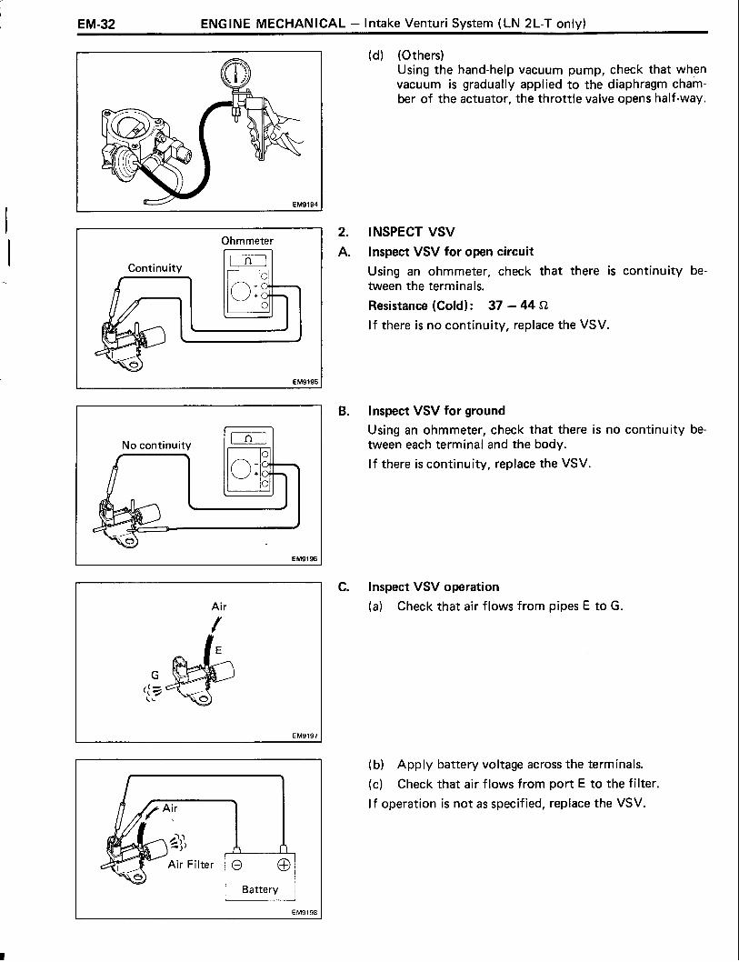
(d) (Others) Using the hand-help vacuum pump, check that when vacuum is gradually applied to the diaphragm cham- ber of the actuator, the throttle valve opens half-way.
Air
INSPECT VSV
lnspect VSV for open circuit
Using an ohmmeter, check that there is continuity be- tween the terminals.
Resistance (Cold) : 37 - 44 !2
I f there is no continuity, replace the VSV.
C.
Inspect VSV for ground
Using an ohmmeter, check that there is no continuity be tween each terminal and the body.
I f there is continuity, replace the VSV.
lnspect VSV operation
(a) Check that air flows from pipes E to G.
(b) Apply battery voltage across the terminals.
(c) Check that air flows from port E to the filter
I f operation is not as specified, replace the VSV.

ENGl NE MECHANICAL - Com~ression Check
COMPRESSION CHECK HINT: I f there is lack of power, excessive oil consump- tion or poor fuel economy, measure the compression pres- sure.
WARM UP AND STOP ENGINE
Allow the engine to reach normal operating temperature.
DISCONNECT INJECTION PUMP (FUEL CUT SOLENOID) CONNECTOR
REMOVE AIR CLEANER
(w/ Intake Pipe) REMOVE INTAKE PIPE
REMOVE GLOW PLUGS
CHECK CYLINDER COMPRESSION PRESSURE
(a) Install SST (attachment) to the glow plug hole.
SST 09992-00024 (09992-001 2 1 )
(b) Connect SST (compression gauge) to SST (attach- ment).
SST 09992-00024 (09992-00 1 2 1,09992-002 1 1 )
(c) Fully open the throttle valve.
(d) While cranking the engine, measure the compression pressure.
HINT: Always use a fully charged battery to obtain engine revolution of 250 rpm or more.
(e) Repeat steps (a) through (d) for each cylinder.
NOTICE: This measurement must be done in as short a time as possible.
Compression pressure: 2L-T 31.0 kg/cm2 (441 psi, 3,040 kPa) or more 3L 32.0 kg/cm2 (455 psi, 3,138 kPa) or more
Minimum pressure: 20.0 kg/cm2 (284 psi, 1,961 kPa)
Difference between each cylinder: 5.0 kg/cm2 (71 psi, 490 kPa) or less

(f) I f the cylinder compression in one or more cylinders is low, pour a small amount of engine oil into the cylinder through the glow plug hole and repeat steps (a) through (d) for the cylinder with lowcompression.
I f adding oil helps the compression, chances are that the piston rings and/or cylinder bore are worn or damaged.
I f pressure stays low, a valve may be sticking or seating improperly, or there may be leakage past the gasket.
REINSTALL GLOW PLUGS
(w/ Intake Pipe) REINSTALL INTAKE PIPE
REINSTALL AIR CLEANER
RECONNECT INJECTION PUMP (FUEL CUT SOLENOID) CONNECTOR

ENGINE MECHANICAL - Cylinder Head (2L-T) EM-35
CYLINDER HEAD (2L-T) COMPONENTS
do.
[
Engine Hanger 4
Cylinder Heat Cover
No. 2 Heat Insulator
e- Valve Lifter Camshaft Bearing Cap ,,,, Keeper
@- Spring Retainer Camshaft Bearing
@-valve Spring
8-+ Oil Seal -Spring Seat
EGR Valve and Pipe
Combustion Chamber
Belt Cover
EGR Valve Adaptor
11
I kg-cm (ft-lb, ~ m ) ] : Specified torque
-
Venturi Assembly
Air Pipe (Austria)
+ Non-reusable part EM92:
EM-36 ENGINE MECHANICAL - Cylinder Head (2L-T)
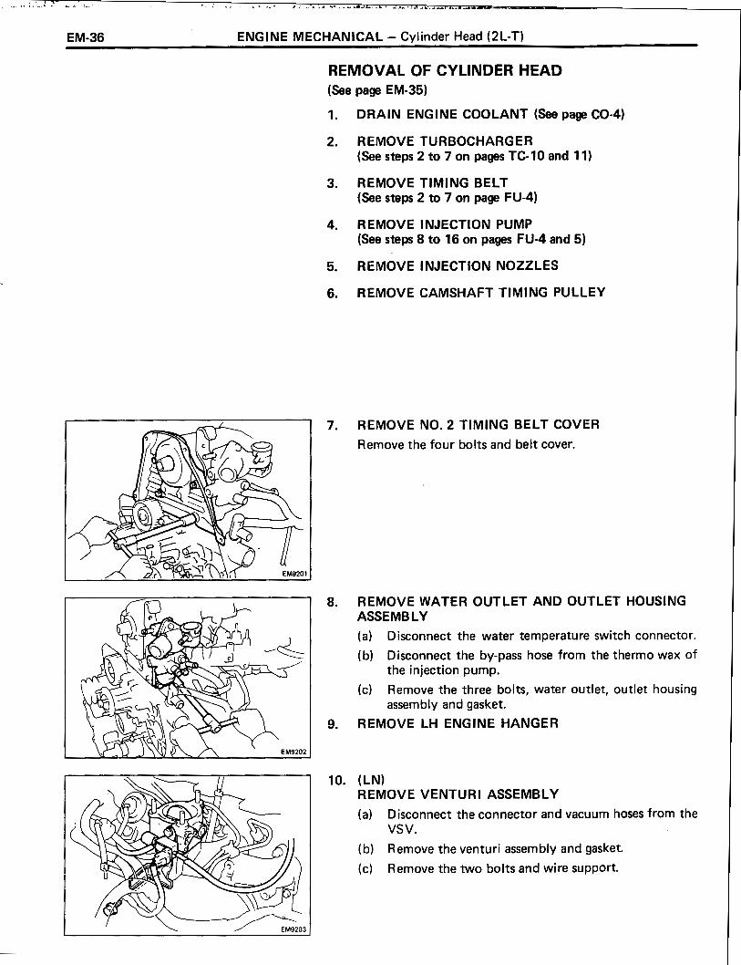
REMOVAL OF CYLINDER HEAD (See page EM-35)
DRAIN ENGINE COOLANT (See page CO-4)
REMOVETURBOCHARGER (See steps 2 to 7 on pages TC- 10 and 1 1 )
REMOVE TIMING BELT (See steps 2 to 7 on page FU-4)
REMOVE INJECTION PUMP (See steps 8 to 16 on pages FU-4 and 5)
REMOVE INJECTION NOZZLES
REMOVE CAMSHAFT TIMING PULLEY
REMOVE NO. 2 TIMING BELT COVER
Remove the four bolts and belt cover.
REMOVE WATER OUTLET AND OUTLET HOUSING ASSEMBLY
(a) Disconnect the water temperature switch connector.
(b) Disconnect the by-pass hose from the thermo wax of the injection pump.
(c) Remove the three bolts, water outlet, outlet housing assembly and gasket.
REMOVE LH ENGINE HANGER
(LN) REMOVE VENTURI ASSEMBLY
(a) Disconnect the connector and vacuum hoses from the VSV.
(b) Remove the venturi assembly and gasket.
(c) Remove the two bolts and wire support.
ENGINE MECHANICAL - Cylinder Head (2L-T) E M-37
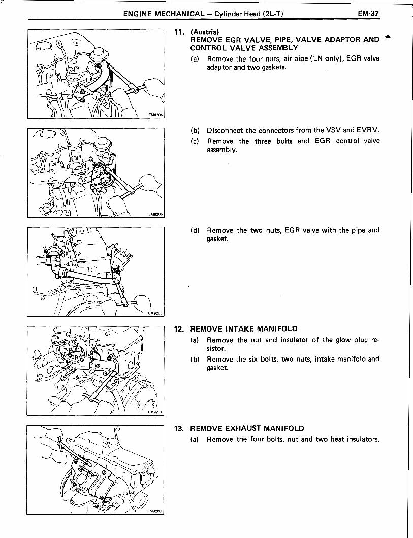
11. (Austria) REMOVE EGR VALVE, PIPE, VALVE ADAPTOR AND )r
CONTROL VALVE ASSEMBLY
(a) Remove the four nuts, air pipe (LN only), EGR valve adaptor and two gaskets.
(b) Disconnect the connectors from the VSV and EVRV.
(c) Remove the three bolts and EGR control valve assembly.
(d) Remove the two nuts, EGR valve with the pipe and gasket.
REMOVE INTAKE MAN1 FOLD
(a) Remove the nut and insulator of the glow plug re- sistor.
(b) Remove the six bolts, two nuts, intake manifold and gasket.
REMOVE EXHAUST MANIFOLD
(a) Remove the four bolts, nut and two heat insulators.

EM-38 ENGINE MECHANICAL - Cylinder Head (2L-T)
(b) Remove the four bolts, four nuts, exhaust manifold and gasket.
14. REMOVE RH ENGINE HANGER
15. REMOVE CYLINDER HEAD COVER
~emove the eight bolts, two nuts, cylinder head cover and gasket.
16. REMOVE CYLINDER HEAD
(a) Uniformly loosen and remove the eighteen cylinder head bolts in several passes in the sequence shown.
NOTICE: Head warpage or cracking could result from removing bolts in incorrect order.
(b) Lift the cylinder head from the dowels on the cy- linder block and place the head on wooden blocks on a bench.
HINT: I f the cylinder head is difficult to l ift off, pry with a screwdriver between the cylinder head and block.
NOTICE: Be careful not to damage the cylinder head and cylinder block surfaces of cylinder head gasket side.

ENGINE MECHANICAL - Cylinder Head (2L-T) EM-39
DISASSEMBLY OF CYLINDER HEAD a
(See page EM-35)
INSPECTION, CLEANING AND REPAIR OF CYLINDER HEAD COMPONENTS
INSPECT CAMSHAFTS AND BEARINGS
B. Inspect cam lobes
Using a micrometer, measure the cam lobe height.
Standard cam lobe height: lntake 2L-T 53.450 - 53.470 mm
(2.1043 - 2.1051 in.) 3L 54.290 - 54.310 mm
(2.1374 - 2.1382 in.) Exhaust 54.990 - 55.010 mm
(2.1650 - 2.1657 in.)
Minimum cam lobe height: lntake 2L-T 52.95 mm (2.0846 in.)
3L 53.79 mm (2.1177 in.) Exhaust 54.49 mm (2.1453 in.)
If the cam lobe height is smaller than the minimum, replace the camshaft.
ASSEMBLY OF CYLINDER HEAD (See page EM-35)
INSTALL HALF CIRCULAR PLUG
(a) Remove any old packing (FIPG) material.
(b) Apply seal packing to the half circular plug as shown.
Seal packing: Part No. 08826-00080 or equivalent
(c) Install the half circular plug to the cylinder head.

EM-40 ENGINE MECHANICAL - Cylinder Head (2L-T)
INSTALLATION OF CYLINDER HEAD (See page EM-35)
CHECK PISTON PROTRUSION AND SELECT CYLINDER HEAD GASKET
Check protrusions of No. 1 and No. 4 pistons
(a) Align the timing marks of the crankshaft timing pulley and timing belt case.
(b) Place a dial indicator on the cylinder block, and set the dial indicator needle on the piston measuring point.
(c) Find where the piston head protrudes most by slowly turning the crankshaft clockwise and counterclock- wise.
(d) Set the dial indicator a t 0 mm (0 in.).
(e) Measure the piston protrusion from the cylinder block by sliding the dial indicator.
Protrusion: 0.68 - 0.97 rnrn (0.0268 - 0.0382 in.)
HINT: For each piston, measure the piston protrusion a t two measuring points.
(When removing piston and connecting rod assembly) I f the protrusion is not as specified, remove the piston and connecting rod assembly and reinstall it.

ENGINE MECHANICAL - Cylinder Head (2L-T) EM-41
Cutout
Mark 0, D or F
Front
I Piston protrusion Gasket size
mm (in.) I 0.68 - 0.77 1 (0.0268 - 0.0303) I use 8 1
0.88 - 0.97 (0.03 16 - 0.0382) I use F I
B. Check protrusions of No. 2 and No. 3 pistons
(a) Turn the crankshaft 112 of a revolution (180"). (b) Measure the piston protrusions.
(See procedure steps A (b) to (e))
C. Select new cylinder head gasket
HINT: There are three sizes of new cylinder head gasket, marked either "B", "D" or "F", or indicated by a cutout mark.
New cylinder head gasket thickness: Mark 5 1.40 - 1 .SO mm
(0.0551 - 0.0591 in.) Mark D 1.50 - 1.60 mm
(0.0591 - 0.0630 in.) Mark F 1.60 - 1.70 mm
(0.0630 - 0.0669 in.)
When selecting a new cylinder head gasket, use the largest value from the eight measurements made of the piston protrusion.
HINT: There are 6 types of cylinder head gasket (marks A to F) installed a t the factory, but only 3 types for sup- ply parts (mark B, D and F), so when replacing the gasket, choose from one of the 3 types above.
SET NO. 1 CYLINDER TO TDCICOMPRESSION
HINT: Set the No. 1 cylinder to TDC/compression to avoid interference with the piston top and valve head.
(a) (Camshaft Position) Set the camshaft by turning the hexagonal wrench head portion, facing the key groove upward.
(b) (Crankshaft Position) Using the crankshaft pulley bolt, align the timing marks of the timing pulley and timing belt case by turning the crankshaft.

EM-42 ENGINE MECHANICAL - Cylinder Head (2L-T)
INSTALL CYLINDER HEAD
Place cylinder head on cylinder block
(a) Place a new cylinder head gasket in position on the cylinder block.
NOTICE: Be careful of the installation direction.
(b) Place the cylinder head in position on the cylinder head gasket.
Install cylinder head bolts
HINT: The cylinder head bolts are tightened in three progres- sive steps. I f any of bolts break or deform, replace them.
(a) Apply a light coat of engine oil on the threads and under the heads of the cylinder head bolts.
(b) First, install and uniformly tighten the eighteen cy- linder head bolts in several passes in the sequence shown.
Torque: 800 kg-cm (58 ft-lb, 78 N-m)
HINT: The bolt lengths for bolt types A and B shown in the illustration are:
A 107 mm (4.12 in.) B 127 mm (5.00 in.)
I f any one of the bolts does not meet the torque specifica- tion, replace the bolt.
(c) Mark the front of the cylinder head bolt with paint.
(d) Second, retighten the cylinder head bolts 90" in the numerical order shown.
(e) Third, retighten cylinder head bolts by an additional 90".
(f) Check that the painted mark is now facing rearward.

ENGINE MECHANICAL - Cylinder Head (2L-T) EM-43
- :Seal Packing ? -
INSTALL CYLINDER HEAD COVER + (a) Apply seal packing to the cylinder heads as shown in
the illustration.
Part No. 08826-00080 or equivalent Seal packing:
(b) l nstall the gasket to the cylinder head cover.
(c) Install the cylinder head cover with the eight bolts and two nuts.
Torque: 50 kg-cm (43 in.-lb, 4.9 N-m)
INSTALL RH ENGINE HANGER
Torque: 380 kg-cm (27 ft-lb, 37 N-m)
INSTALL EXHAUST MANIFOLD
(a) Install a new gasket in direction as shown in the illust- ration.
(b) Install the exhaust manifold with the four nuts and four bolts.
Torque: 530 kg-cm (38 ft-lb, 52 N-m)
(c) Install the two heat insulators with the four bolts and nut.
Torque: 120 kg-cm (9 ft-lb, 12 Nmm)

EM-44 ENGINE MECHANICAL - Cvlinder Head (2L-T)
INSTALL INTAKE MANIFOLD
(a) lnstall a new gasket and the intake manifold with the six bolts and two nuts.
Torque: 240 kg-cm (17 ft-lb, 24 N-m) HINT: Torque the three bolts on the bottom of the manifold together with the oil level gauge guide support and the clamp for the engine wires, as shown in the illustra- tion.
(b) lnstall the insulator and nut to the glow plug resistor.
HINT: lnstall the insulator and engine wire terminals as shown in the illustration.
(Austria) INSTALL EGR VALVE, PIPE, VALVE ADAPTOR AND CONTROL VALVE ASSEMBLY
(a) Place a new gasket in position on the intake manifold.
(b) lnstall the EGR valve and pipe with the two nuts.
Torque: 130 kg-cm (9 in.-lb, 13 N-m)
(c) l nstall the EG R control valve assembly with the three bolts.
(d) Connect the connectors to the VSV and EVRV.
(e) lnstall two new gaskets, the EGR valve adaptor and air pipe (LN only) with the four nuts.
Torque: 195 kg-cm (14 ft-lb, 19 N-m)

Y "
ENGINE MECHANICAL - Cylinder Head (2L-T) EM-45
9. (LN) a INSTALL VENTURI ASSEMBLY
(a) Install the wire support with the two bolts.
(b) l nstall a new gasket and the venturi assembly.
(c) Connect the connector and vacuum hoses to the VSV.
10. INSTALL LH ENGINE HANGER
Torque: 380 kg-cm (27 ft-lb, 37 Nnm)
INSTALL WATER OUTLET AND OUTLET HOUSING ASSEMBLY
(a) l nstall a new gasket, the water outlet and outlet hous- ing assembly with the three bolts.
Torque: 195kg-cm(14ft-lb,19N-m)
(b) Connect the by-pass hose to the thermo wax of the injection pump.
(c) Connect the water temperature switch connector.
12. INSTALL NO. 2 TIMING BELT COVER
Install the timing belt cover with the four bolts.
Torque: 185 kg-cm (13 ft-lb, 18 N-m)
13. INSTALL CAMSHAFT TIMING PULLEY
14. INSTALL INJECTION NOZZLES
15. INSTALL INJECTION PUMP (See steps 2 to 11 on pages FU-46 and 47)
16. INSTALL TIMING BELT (See steps 12 to 18 on page FU-48)
17. INSTALL TURBOCHARGER (See steps 3 to 8 on pages TC-13 and 14)
18. FILL WITH ENGINE COOLANT (See page CO-5)
19. START ENGINE AND CHECK FOR LEAKS
20. RECHECK ENGINE COOLANT LEVEL AND OIL LEVEL

EM-46 ENGINE MECHANICAL - Cylinder Block
Thrust @ Direction
Front c Axial
@ Direction
10 rnrn
10 rnrn (0.39 in.)
CYLINDER BLOCK INSPECTION OF CYLINDER BLOCK
INSPECT CYLINDER BORE DIAMETER HINT: There are three sizes of the standard cylinder bore diameter, marked "I", "2" and "3" accordingly. The mark is stamped on the lower left rear of the cylinder block.
Using a cylinder gauge, measure the cylinder bore diameter a t positions A, B and C in the thrust axial directions.
Standard diameter: 2L-T STD mark "1" 92.000 - 92.010 mm
(3.6220 - 3.6224 in.) STD mark "2" 92.010 - 92.020 mm
(3.6224 - 3.6228 in.) STD mark "3" 92.020 - 92.030 mm
(3.6228 - 3.6232 in.) 3L STD mark "1" 96.000 - 96.010 mm
(3.7795 - 3.7799 in.) STD mark "2" 96.010 - 96.020 mm
(3.7799 - 3.7803 in.) STD mark "3" ,96.020 - 96.030 mm
(3.7803 - 3.7807 in.)
Maximum diameter: 2L-T STD 92.23 mm (3.631 1 in.)
01s 0.50 92.73 mm (3.6508 in.) 3L STD 96.23 mm (3.7886 in.)
01s 0.50 96.73 mm (3.8083 in.)
I f the diameter is greater than maximum, rebore al l four cylinders. I f necessary, replace the cylinder block.
INSPECTION OF PISTON AND CONNECTING ROD ASSEMBLIES
1. INSPECT PISTON DIAMETER AND OIL CLEARANCE
HINT: There are three sizes of the standard piston dia- meter, marked "I", "2" and "3" accordingly. The mark is stamped on the top of the piston.
(a) Using a micrometer, measure the piston diameter a t right angles to the piston pin center line, the indi- cated distance from the piston head.
Distance: 2L-T 58.27 - 58.33 mm (2.2941 - 2.2965 in.) 3L 56.27 - 56.33 mm (2.2153 - 2.2177 in.)

ENGINE MECHANICAL - Cylinder Block EM-47
Piston diameter: 2L-T STD mark "1" 91.940 - 91.950 mm
(3.6197 - 3.6201 in.) STD mark "2" 91.950 - 91.960 mm
(3.6201 - 3.6205 in.) STD mark "3" 91.960 - 91.970 mm
(3.6205 - 3.6209 in.) 01s 0.50 92.440 - 92.470 mm
(3.6394 - 3.6405 in.)
Piston diameter: 3L STD mark "1" 95.940 - 95.950 mm
(3.7772 - 3.7776 in.) STD mark "2" 95.950 - 95.960 mm
(3.7776 - 3.7779 in.) STD mark "3" 95.960 - 95.970 mm
(3.7779 - 3.7783 in.) 01s 0.50 96.440 - 96.470 mm
(3.7968 - 3.7980 in.)
(b) Measure the cylinder bore diameter in the thrust directions. (See page EM-46)
(c) Subtract the piston diameter measurement from the cylinder bore diameter measurement.
Front Mark 1,201-3
EM5482 EM568C
Standard oil clearance: 0.050 - 0.070 mm (0.0020 - 0.0028 in.)
Maximum oil clearance: 0.14 mm (0.0055 in.)
I f the oil clearance is greater than maximum, replace a l l four pistons and rebore all four cylinders. I f necessary, replace the cylinder block.
HINT (Use cylinder block subassembly): When installing a standard piston, install one with the same number mark as the standard bore diameter mark on the cylinder block.
INSPECT CLEARANCE BETWEEN WALL OF RING GROOVE AND NEW PISTON RING
(No. 1 Ring)
Install a No. 1 piston ring to the piston. Using a feeler gauge, measure the clearance between the piston ring and wall of the piston ring groove.
Standard ring groove clearance: No. 1 0.028 - 0.077 mm (0.001 1 - 0.0030 in.)
Maximum ring groove clearance: 0.20 mm (0.008 in.)
I f the clearance is greater than maximum, replace the piston.

EM-48 ENGINE MECHANICAL - Cylinder Block
No. 2 and Oil Rings
essed
(No.2 and Oil Rings)
Using a feeler gauge, measure the clearance between new piston ring and the wall of the piston ring groove.
Standard ring groove clearance: No. 2 2L-T 0.070 - 0.1 15 mm
(0.0028 - 0.0045 in.) 3L 0.060 - 0.105 mm
(0.0024 - 0.0041 in.) Oil 0.030 - 0.070 mm
(0.0012 - 0.0028 in.)
Maximum ring groove clearance: 0.20 mm (0.008 in.)
I f the clearance is greater than maximum, replace the piston.
INSPECT CONNECTING ROD
Inspect connecting rod alignment
Using a rod aligner, check the connecting rod alignment.
0 Check for bending.
Maximum bending: 0.05 mm (0.0020 in.) per 100 mm (3.94 in.)
I f bent is greater than maximum, replace the connecting rod assembly.
Check for twist.
Maximum twist: 0.15 mm (0.0059 in.) per 100 mm (3.94 in.)
I f twist is greater than maximum, replace the connecting rod assembly.
l nspect connecting rod bolts
Using vernier calipers, measure the minimum diameter of the compressed bolt a t the measuring point.
Standard diameter: 8.400 - 8.600 mm (0.3307 - 0.3386 in.)
Minimum diameter: 8.20 mm (0.3228 in.)
I f the diameter is less than minimum, replace the connect- ing rod bolt.

1 ENGINE MECHANICAL - Cylinder Block EM-49
C. Inspect piston pin oil clearance a
(a) Using a caliper gauge, measure the inside diameter of the connecting rod bushing.
Bushing inside diameter: 29.008 - 29.020 mm (1.1420 - 1.1425 in.)
tance
(b) Using a micrometer, measure the piston pin diameter.
Piston pin diameter: 29.000 - 29.012 mm (1.1417 - 1.1422 in.)
(c) Subtract the piston pin diameter measurement from the bushing inside diameter measurement.
I Standard oil clearance: 0.004 - 0.012 mm
(0.0002 - 0.0005 in.)
Maximum oil clearance: 0.05 mm (0.0020 in.)
BORING OF CYLINDERS
HINT: Bore all four cylinders for the oversized piston outside diameter.
Replace the piston rings with ones to match the over- sized pistons.
KEEP OVERSIZED PISTONS
Oversized (01s 0.50) piston diameter: 2L-T 92.440 - 92.470 mm (3.6394 - 3.6405 in.) 3L 96.440 - 96.470 mm (3.7968 - 3.7980 in.)
CALCULATE AMOUNT TO BORE CYLINDER
(a) Using a micrometer, measure the piston diameter a t right angles to the piston pin center line, the indicat- ed distance from the piston head.
Distance: 2L-T 58.27 - 58.33 mm (2.2941 - 2.2965 in.) 3L 56.27 - 56.33 mm (2.2153 - 2.2177 in.)
(b) Calculate the amount each cylinder is to be rebored as follows:
Size to be rebored = P + C - H P = Piston diameter C = Piston oil clearance
0.05 - 0.07 mm (0.0020 - 0.0028 in.) H = Allowance for honing
0.02 mm (0.0008 in.) or less
BORE AND HONE CYLINDERS TO CALCULATED DIMENSIONS
Maximum honing: 0.02 mm (0.0008 in.)
NOTICE: Excess honing will destroy the finished round- ness.

EM-50 ENGINE MECHANICAL - Cylinder Block
INSPECTION AND REPAIR OF CRANKSHAFT
Crank Pin Diameter
Crank Journal Diameter
INSPECT CRANKSHAFT FOR RUNOUT
(a) Place the crankshaft on V-blocks.
(b) Using a dial indicator, measure the circle runout a t the center journal.
Maximum circle runout: 0.06 mm (0.0024 in.)
I f the circle runout is greater than maximum, replace the crankshaft.
2. INSPECT MAIN JOURNALS AND CRANK PINS
(a) Using a micrometer, measure the diameter of each main journal and crank pin.
Main journal diameter: STD 61.985 - 62.000 mm
(2.4403 - 2.4409 in.) U/S 0.25 61.745 - 61.755 mm
(2.4309 - 2.4313 in.) U/S 0.50 61.495 - 61.505 mm
(2.4211 - 2.4215 in.)
Crank pin diameter: STD 54.988 - 55.000 mm
(2.1649 - 2.1654 in.) U/S 0.25 54.745 - 54.755 mm
(2.1553 - 2.1557 in.) U/S 0.50 54.495 - 54.505 mm
(2.1455 - 2.1459 in.)
If the diameter is not as specified, check the oil clearance.
(b) Check each main journal and crank pin for taper and out-of-round as shown.
Maximum taper and out-of-round: 0.02 mm (0.0008 in.)
If the taper or out-of-round is greater than maximum, grind or replace the crankshaft.
IF NECESSARY, GRIND AND HONE MAIN JOURNALS AND/OR CRANK PINS
Grind and hone the main journals and/or crank pins to the finished undersized diameter (See procedure step 2).
Install new main journal and/or crank pin undersized bear- ings.
ASSEMBLY OF CYLINDER BLOCK The connecting rod cap nut tightening torque has been changed as follows:
Torque: Previous 1st 550 kg-cm (40 ft-lb, 54 N-m)
2nd 90" turns
New t
1st 350 kg-cm (25 ft-lb, 34 N-m) 2nd 120" turns


T G 2 TURBOCHARGER SYSTEM - Description
DESCRIPTION
Water Cooling Channel
\
Full-Floating Bearing Impeller Wheel /
Wheel
\ Waste Gate Valve
Full-Floating Be aring
Svstems which increase the amount of air sent air to the engine. This allows a proportional in- to the engine are either turbocharger type (using crease in thefuel that can be burned and hence exhaust gas to turn the turbine) or supercharger raises the potential power output. type (using the engine crankshaft, etc. to mechani- In other words, by installing a special turbo- cally turn the pump, etc.). For LAND CRUISER charger and providing a higher air than usual, and 4 RUNNER 2L-T engine, the turbocharger engine output can be increased by increasing the type has been adopted. average combustion pressure without increasing
The turbocharger is a device which increases the engine speed. engine output by introducing a greater amount of

TURBOCHARGER SYSTEM - Description TC-3
Turbocharger
Operation of Turbocharger Waste Gate Valve
Exhaust gas acts on the turbine wheel inside the turbine housing, causing it to revolve. When the turbine wheel revolves, the impeller wheel which is located on the same shaft also revolves, compres- sing the intake air which has passed through the air cleaner. When expelled from the compressor hous- ing the compressed air i s supplied to the cylinders: When the engine speed increases, the exhaust gas volume increases and the turbine wheel revolutions increase (approx. 20,000 - 1 15,000 rpm), thus the turbocharged air pressure grows greater and engine output increases.
If the turbocharged air pressure exceeds the prescribed air pressure, the flow of exhaust gas by-passes the turbine, controlling turbine wheel revolutions and turbocharged air pressure. This by-pass valve which controls the quantity of ex- haust gas flowing to the turbine is called the waste gate valve. When the charged air pressure exceeds the prescribed pressure, the actuator operates, the waste gate valve opens and part of the exhaust gas by-passes the turbine. This causes a drop in the turbine revolution rate and controls the charged air pressure within the prescribed limits.

TC-4 TURBOCHARGER SYSTEM - Precautions
PRECAUTIONS
No! / i
Do not stop the engine immediately after pulling a trailer or high speed or uphill driving. Idle the engine for 20 - 120 seconds, depending on the severity of the driving con- dition.
Avoid sudden racing or acceleration immediately after starting a cold engine.
I f the turbocharger is defective and must be replaced, first check for the cause of the defect in reference to the fol- lowing items and replace parts i f necessary:
Engine oil level and quality
Conditions under which the turbocharger was used
Oil lines leading to the turbocharger
Use caution when removing and reinstalling the turbo- charger assembly. Do not drop it or bang it against any- thing or grasp it by easily-deformed parts, such as the actuator or rod, when moving it.
Before removing the turbocharger, plug the intake and exhaust ports and oil inlet to prevent entry of dirt or other foreign material.
I f replacing the turbocharger, check for accumulation of sludge particles in the oil pipes and, i f necessary, replace the oil pipes.
Completely remove the gasket adhered to the lubrication oil pipe flange and turbocharger oil flange.
If replacing bolts or nuts, do so only with the specified new ones to guard against breakage or deformation.
If replacing the turbocharger, put 20 cc (1.2 cu in.) of oil into the turbocharger oil inlet and turn the impeller wheel by hand to spread oil to the bearing.
If overhauling or replacing the engine, cut the fuel supply after reassembly and crank the engine for 30 seconds to distribute oil throughout the engine. Allow the engine to idle for 60 seconds.

TURBOCHARGER SYSTEM - Precautions, Troubleshooting TC-5
11. I f the engine is running with the air cleaner, case cover and , hose removed, entry of foreign particles will damage the wheels which run at extremely high speed.
TROUBLESHOOTING HINT: Before troubleshooting the turbocharger, first check the engine itself. (Valve clearance, engine compres- sion, injection timing etc.)
INSUFFICIENT ACCELERATION, LACK OF POWER OR EXCESSIVE FUEL CONSUMPTION
(Possible Cause) (Check Procedure and Correction Method)
1. TURBOCHARGING PRESSURE TOO I LOW t Check turbocharging pressure. (See page TC-8)
Turbocharging pressure: 0.61 - 0.81 kg/cm2 (8.7 - 11.5 psi, 60 - 79 kPa)
I f the pressure i s below specification, begin diagnosis from item 2.
Check intake air system, and repair or replace parts as necessary. (See page TC-8)
3. LEAK IN IN Check intake air system, and repair or replace parts as necessary. (See page TC-8)
4. RESTRICTED EXHAUST SYSTEM Check exhaust system, and repair or replace parts as necessary. (See page TC-8)
5. LEAK IN EXHAUST SYSTEM Check exhaust system, and repair or replace parts as necessary. (See page TC-8)
Check plays of turbine shaft. (See page TC-12) I
6. ERRATIC TURBOCHARGER OPERATION
Axial play: 0.13 mm (0.0051 in.) or less Radial play: 0.18 mm (0.0071 in.) or less
I f not within specification, replace the turbocharger assembly.
assembly. 1 ' Check rotation of impeller wheel. I f it does not turn - or turns with a heavy drag, replace the turbocharger

TC-6 TURBOCHARGER SYSTEM - Troubleshooting
ABNORMAL NOISE
(Possible Cause) (Check Procedure and Correction Method)
1. TURBOCHARGER INSULATOR RESONANCE
3. ERRATIC TURBOCHARGER I OPERATION 1
\ -' Check for loose, improperly installed or deformed insulator mounting bolts and nuts, and repair or
2. EXHAUST PIPE LEAKING OR VIBRATING
Refer to item 6 of INSUFFICIENT ACCELERA- 3
TION, LACK OF POWER OR EXCESSIVE FUEL CONSUMPTION.
replace as necessary.
EXCESSIVE OIL CONSUMPTION OR WHITE EXHAUST
necessary.
' Check for exhaust pipe deformation, loose mounting '
(Possible Cause)
-
(Check Procedure and Correction Method)
bolts or a damaged gasket, and repair or replace as
I FAULTY TURBOCHARGER OIL SEAL Check for oil leakage in exhaust system. Remove the turbine elbow from the turbocharger and check for excessive carbon deposits on the turbine wheel. Excessive carbon deposits would indicate a faulty turbocharger.
Check for oil leakage in intake air system. Check plays of turbine shaft, and replace the turbocharger i f necessary. (See page TC- 12)
Axial play: 0.13 mm (0.0051 in.) or less Radial play: 0.18 mm (0.0071 in.) or less

TURBOCHARGER SYSTEM - Turbocharger Electrical System Diagnosis TC-7
TURBOCHARGER ELECTRICAL SYSTEM DIAGNOSIS a
I Check CHARGE and Blown Check for short circuit ENGINE fuses and repair as necessary I
TROUBLESHOOTING OF TURBOCHARGER INDICATOR LIGHT AND WARNING LIGHT OPERATION
I s charge warning N 0 Faulty charging light out? system
Do both green indicator light and amber warning light light when ignition switch is turned to ON?
I I L I
l YES
NO Check GAUGE fuse
Check for short circuit and repair as necessary
YES
Faulty combination meter
Are indicator and warning lights out during engine idle? I
I I Both lights stay on
Is charge warning light out?
I I Green light stays on
Faulty low pressure switch and tachometer. switch
Amber light comes on
Check for open circuit in Faulty high pressure and tachometer and check for ground connection of switch. switch
l YES t
Does green indicator light come on when 0.14 kg/cm2 of (2.0 psi, 13.7 kPa) pressure is applied to both pressure switches?
Check for short circuit in wire harness between low pressure Faulty low pressure switch and tachometer. switch
YES
Amber light comes on
I YES - Faulty combination meter
Does green indicator light come on when 0.85 kglcrn"l2.1 psi, 83 kPa) of NO
pressure i s applied to both switches? SST 09992-00241 -
Does amber indicator light come on when 0.85 kg/cm2 of (12.1 psi, 83 kPa) pressure is applied to both switches?
NO
Faulty high pressure switch
Check for short circuit in wire harness between high pressure Faulty high pressure switch and tachometer.
lyES ,
switch
indicator light and warning light operation okay. I

TC-8 TURBOCHARGER SYSTEM - Turbocharger
TURBOCHARGER ON-VEHICLE INSPECTION OF TURBOCHARGER
2,400 rpm or more
\ S S T
INSPECT INTAKE AIR SYSTEM
Check for leakage or clogging between the air cleaner and turbocharger inlet and between the turbocharger outlet and cylinder head.
Clogged air cleaner .... Clean or replace the element
Hoses collapsed or deformed .... Check each connection and repair
Cracks in components .... Check and replace
INSPECT EXHAUST SYSTEM
Check for leakage or clogging between the cylinder head and turbocharger inlet and between the turbocharger out- let and exhaust pipe.
Deformed components .... Repair or replace
Foreign material in passages .... Remove
Leakage from components .... Repair or replace
Cracks in components .... Check and replace
CHECK TURBOCHARGING PRESSURE
(a) Warm up the engine.
(b) Connect a 3-way union to the intake pipe pressure hose and install SST (turbocharger pressure gauge) to it.
SST 09992-0024 1
(b) Press in the clutch pedal, then press the accelerator pedal down as far as it will go. Measure the turbo- charging pressure a t 2,400 rpm or more.
Standard pressure: 0.61 - 0.81 kg/cm2 (8.7 - 11.5 psi, 60 - 79 kPa)
I f the pressure is less than specification, check the intake air and exhaust systems for leakage. I f there is no leakage, replace the turbocharger assembly. I f the pressure is above specification, check if the actuator hose is disconnected or cracked. I f not, replace the turbo- charger assembly.
INSPECT IMPELLER WHEEL ROTATION
(a) Disconnect the air cleaner hose.
(b) Grasp the edge of the impeller wheel and turn it. Check that it turns smoothly.
I f it does not turn or if it turns with a drag, replace the turbocharger assembly.

i TURBOCHARGER SYSTEM - Turbocharger TC-9
COMPONENTS
Intake Pipe
kg-cm (ft-lb, N m ) 1 : Specified torque
+ Non-reusable part

TGlO TURBOCHARGER SYSTEM - Turbocharger
I I REMOVAL OF TURBOCHARGER (See page TC-9)
1. DRAIN ENGINE COOLANT (See page CO-4)
2. REMOVE INTAKE PlPE
(a) Disconnect the vacuum hoses for the boost compen- sator.
(b) Disconnect the air hose clamp bolt.
(c) Remove the three nuts, intake pipe and gasket.
3. DISCONNECT WATER BY-PASS HOSES
4. REMOVE TURBO HEAT INSULATORS
Remove the four bolts and three heat insulators.
5. REMOVE EXHAUST MANIFOLD STAY
Remove the two bolts, two nuts and exhaust manifold stay.
6. REMOVE TURBO OIL PlPE
(a) Remove the union bolt and two gaskets holding the turbo oil pipe to the cylinder block.
(b) Disconnect the turbo oil hose.
(c) Remove the two nuts, turbo oil pipe and gasket.

TURBOCHARGER SYSTEM - Turbocharger TC-11
7. REMOVE TURBOCHARGER FROM EXHAUST 4
MAN l FOLD Remove the four nuts, turbocharger and gasket.
8. REMOVE TURBO WATER PIPE Remove the bolt and two nuts, turbo water pipe and gasket.
9. REMOVETURBINEOUTLETELBOW Remove the four nuts, turbine outlet elbow and gasket.
INSPECTION OF TURBOCHARGER
1. INSPECT IMPELLER WHEEL ROTATION Grasp the edge of the turbine wheel and turn it. Check that the impeller wheel turns smoothly.
I f the impeller wheel does not turn or i f it turns with a drag, replace the turbocharger assem bly.
2. INSPECT AXIAL PLAY OF IMPELLER WHEEL Insert a dial indicator into the intake side, hold the turbine wheel edge by hand and check the axial play.
Axial play: 0.13 mm (0.0051 in.) or less
I f the axial play is not as specified, replace the turbocharger assembly.

TC- 12 TURBOCHARGER SYSTEM - Turbocharger
INSPECT RADIAL PLAY OF TURBINE SHAFT
(a) From the oil outlet hole, insert the dial indicator through the hole in the spacer bearing and set it in the center of the turbine shaft.
(b) Moving the turbine shaft in a radial direction, meas- ure the radial play of the shaft.
Radial play: 0.18 mm (0.0071 in.) or less
I f the radial play is not as specified, replace the turbo- charger assembly.
4. INSPECT ACT1 JATOR OPERATION
(a) Disconnect the actuator hose.
(b) Using SST (turbocharger pressure gauge), apply ap- prox. 0.81 kg/cm2 (1 1.5 psi, 79 kPa) of pressure to the actuator and check that the rod moves.
SST 09992-00241
I f the rod does not move, replace the turbocharger assem- bly.
NOTICE: Never apply more than 0.95 kg/cm2 (13.5 psi, 94 kPa) of pressure to the actuator.
NOTICE: After replacing the turbocharger assembly, pour approx. 20 cc (1.2 cu in.) of new oil into the oil inlet and turn the impeller wheel by hand to splash oil on the bearing.
INSTALL TURBINE OUTLET ELBOW
l nstall a new gasket and the turbine outlet elbow with the four nuts.
Torque: 260 kg-cm (19 ft-lb, 25 N-m)

TURBOCHARGER SYSTEM - Turbocharaer TC- 13
2. INSTALL TURBO WATER PIPE + lnstall a new gasket and the water pipe with the two nuts and bolt.
Torque: 80 kgcm (69 in.-lb, 7.8 N-m)
3. INSTALL TURBOCHARGER TO EXHAUST MAN I FOLD
(a) lnstall a new gasket to the exhaust manifold.
(b) lnstall the turbocharger with the four nuts.
Torque: 530 kg-cm (38 ft-lb, 52 Nom)
4. INSTALL TURBO OIL PlPE
(a) lnstall a new gasket and the turbo oil pipe with the two nuts.
Torque: 195 kg-cm (14 ft-lb, 19 N-m)
(b) Connect the turbo oil hose.
(c) lnstall two new gaskets and the union bolt of the turbo oil pipe.
Torque: 260 kgcm (19 ft-lb, 25 N-m)
5. INSTALL EXHAUST MANIFOLD STAY lnstall the exhaust manifold stay with the two bolts and two nuts.
Torque: 195 kg-cm ( 14 ft-lb, 19 N-m)

TC-14 TURBOCHARGER SYSTEM - Turbocharger
6. INSTALL TURBOCHARGER HEAT INSULATOR Install the three heat insulators with the four bolts.
Torque: 120 kg-cm (9 ft-lb, 12 N-m)
7. CONNECT WATER BY-PASS HOSES
8. INSTALL INTAKE PIPE
(a) Connect the air hose and install a new gasket and the intake pipe with the three nuts.
Torque: 120 kg-cm (9 ft-lb, 12 Nsm)
(b) Connect boost compensator vacuum hoses.
9. Fl LL ENGINE WITH COOLANT (See page CO-5)
10. START ENGINE AND CHECK FOR LEAKS
11. CHECK ENGINE OIL LEVEL

FU- 1
FUEL SYSTEM REFER TO 2L. 3L ENGINE REPAIR MANUAL (Pub. No. RM123E)
NOTE: The following pages contain only the points which differ from the above listed manual.
Page
FUEL HEATER SYSTEM (LJ) ................................... FU-2
INJECTION PUMP ................................................. FU-3
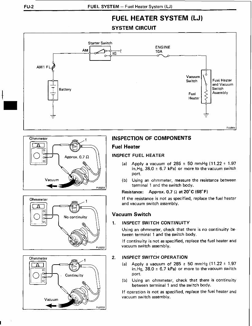
FU-2 FUEL SYSTEM - Fuel Heater System (LJ)
FUEL HEATER SYSTEM (LJ) SYSTEM CIRCUIT
Starter Switch ENGINE 10A
I Battery
Vacuum Switch
Fuel Heater
Fuel Heater and Vacuum Switch Assembly
Ohmmeter
Ohmmeter
\ Continuity I I
Vacuum K
INSPECTION OF COMPONENTS
Fuel Heater
INSPECT FUEL HEATER
(a) Apply a vacuum of 285 t 50 mmHg (1 1.22 It 1.97 in.Hg, 38.0 t 6.7 kPa) or more to the vacuum switch port.
(b) Using an ohmmeter, measure the resistance between terminal 1 and the switch body.
Resistance: Approx. 0.7 L! a t 20°C (68" F)
I f the resistance is not as specified, replace the fuel heater and vacuum switch assembly.
Vacuum Switch
INSPECT SWITCH CONTINUITY
Using an ohmmeter, check that there is no continuity be- tween terminal 1 and the switch body.
I f continuity is not as specified, replace the fuel heater and vacuum switch assembly.
INSPECT SWITCH OPERATION
(a) Apply a vacuum of 285 r 50 mmHg (1 1.22 ? 1.97 in.Hg, 38.0 r 6.7 kPa) or more to the vacuum switch port.
(b) Using an ohmmeter, check that there is continuity between terminal 1 and the switch body.
I f operation is not as specified, replace the fuel heater and vacuum switch assembly.

FUEL SYSTEM - Injection Pump F U-3
INJECTION PUMP REMOVAL OF INJECTION PUMP
Turbo Water Hose (2L-T) I
Thermo Wax Water By-Pass Hose (2L-T)
Fuel Hose I
Fan
1 1,700 (123, 167)
I &-clamp Crankshaft Pulley
No. 1 Timing Belt Cover Injection Pipe
Accelerator Linkage
Injection Pump Stay
Y/O HAC Fuel Outlet Pipe
. I
250 (18.25) ] + Gasket
Fuel lnlet Pipe
[ kg-cm (ft-lb, N m ) 1 : Specified torque
Non-reusable part

F U-4 FUEL SYSTEM - lniection P u m ~
1. (2L-T) DRAIN ENGl NE COOLANT (See page CO-4)
2. (2L-T) REMOVE TURBO WATER HOSE
3. REMOVE DRIVE BELTS, FAN AND WATER PUMP PULLEY
4. REMOVE CRANKSHAFT PULLEY
5. REMOVE NO. 1 TIMING BELT COVER
6. SET NO. 1 CYLINDER TO TDCICOMPRESSION
7. REMOVE TIMING BELT
8. REMOVE INJECTION PUMP DRIVE PULLEY
9. REMOVE ACCELERATOR LINKAGE
10. (2L-T) DISCONNECT BOOST COMPENSATOR HOSE
11. (wl AIC) DISCONNECT A/C IDLE-UP VACUUM HOSE
12. (2L-T) DISCONNECT WATER BY-PASS HOSES FROM THERMO WAX
13. DISCONNECT INJECTION PUMP CONNECTOR(S)
14. DISCONNECT FUEL HOSES FROM INJECTION PUMP
15. REMOVE INJECTION PIPES
(a) Loosen the union nuts of the injection pipes from the injection nozzles.
(b) Loosen the union nuts of the injection pipes from the injection pump.
(c) Remove the four clamps and injection pipes.
NOTICE: On vehicles with PIJ (2L-T Austria), do not interfere with the PIJ actuator with the spanner. Use a 14 mm spanner when loosening the union nut of the No. 2 injection pipe.
16. REMOVE INJECTION PUMP
(a) Remove the four bolts and pump stay.
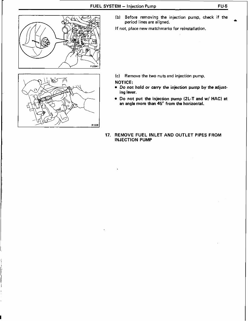
FUEL SYSTEM - lniection P u m ~ FU-5
(b) Before removing the injection pump, check period lines are aligned.
I f not, place new matchmarks for reinstallation.
the
(c) Remove the two nuts and injection pump.
NOT ICE : Do not hold or carry the injection pump by the adjust- ing lever.
Do not p i t the injection pump (2L-T and w/ HAC) at an angle more than 45" from the horizontal.
17. REMOVE FUEL INLET AND OUTLET PIPES FROM INJECTION PUMP

FU-6 FUEL SYSTEM - Injection Pump
COMPONENTS
2L-T
Diaphragm cover
@- Shim B (Austria)
8- Sub Spring (Austria)
Throttle Position Sensor (Austria)
Adjusting Lever
!-- Push Rod
Main Spring Maximum Speed Adjusting Screw
Lever Return Spring
Adjusting Lever Shaft
F
I Idle Speed Adjusting Screw
Control Lever
- Support Pin
7% )-Ring+
Fuel Inlet Hollow Screw
/---+ Gasket
Regulator Valve -
Non-reusable part FU29i

FUEL SYSTEM - Injection Pump FU-7
COMPONENTS (Cont'd)
W/ HAC
Pneumatic 6 Bellows Cover \- Gasket
Rubber
Cao
Shim
Push Rod Connecting Pin
Control Lever Control Lever Support Pin +Gasket '%
Adjusting Lever
,Lever Return Spring
-/ Maximum Speed Adjusting Screw
Governor Cover Idle Speed Adjusting Screw
Adjusting Lever Shaft
Speed Control Spring
Non-reusable part
Pump Body
FU2922
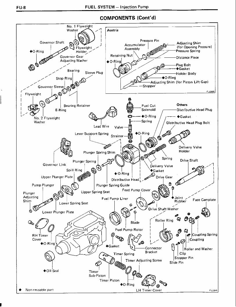
F U-8 FUEL SYSTEM - Injection Pump
COMPONENTS (Cont'd)
n I
I I
/ J
Plug
Austria
Pressure Pin Adjusting Shim (for Opening Pressul Pressure Spring
Distance Piece
Plug Bolt +Gasket Holder Body
ng Shim (for Piston Lift Gap)
I I Bearing I Retainer Fuel Cut Others I E-Ring Solenoid Distributive Head Plug I / ,.'
-Spring / / Distributive Head Plua Bolt No. 2' Flyweight Washer -
Governor Link
Ru,bbe; pace Lamplate /
6 ' 9 _ Drive Shaft Washer
Distributive Head
Feed Pump Cover
Timer S~r ina . - Istopper Pin
Timer Adjusting Screw I Slide Pin
Timer Sub-piston
~ i m e r ' Piston +O-Ring d
+ Non-reusable part LH ~ i m ' e r Cover FU294!

FUEL SYSTEM - Injection Pump FU-9
I 1 DISASSEMBLY OF INJECTION PUMP c
SST
(See pages FU-6 to 8)
1. MOUNT PUMP ASSEMBLY TO SST (STAND)
SST 09241-76022 and 09245-5401 0
REMOVE SET KEY OF DRIVE PULLEY FROM DRIVE SHAFT
( w l AIC) REMOVE IDLE-UP ACTUATOR
(wl Tachometer) REMOVE PICKUP SENSOR
(a) Disconnect the lead wires from the connector.
(b) Remove the pickup sensor and O-ring.
(2L-T Austria) REMOVE THROTTLE POSITION SENSOR
Using a 5 mm hexagonal wrench, remove the three bolts and throttle position sensor.
(2 L-T) REMOVE IDLE-UP LEVER
Using a 5 mm hexagonal wrench, remove the three bolts and idle-up lever.
(2 L-T) REMOVE THERMO WAX
(a) Using a screwdriver, turn the cold starting lever counterclockwise approx. 20".
(b) Put a metal plate (thickness of 8.5 - 10 mm (0.335 - 0.394 in.)) between the cold starting lever and thermo wax plunger.

FU-10 FUEL SYSTEM - Injection Pump
(c) Using a 5 mm hexagonal wrench, remove the two bolts, thermo wax and O-ring.
(2 L-T) REMOVE DASH POT
Remove the dash pot and gasket.
REMOVE FUEL CUT SOLENOID
(a) Using a 6 mm hexagonal wrench, remove the bolt and connector bracket.
(b) Disconnect the lead wire connector from the bracket.
(c) Disconnect the dust cover from the fuel cut solenoid.
(d) Remove the nut, lead wire and dust cover.
(e) Remove the fuel cut solenoid, O-ring, spring, valve, strainer and wave washer.
REMOVE ADJUSTING LEVER
Remove the bolt, nut, adjusting lever and return spring.

FUEL SYSTEM - Injection Pump FU-11
11. REMOVE GOVERNOR COVER + (a) (2L-T and w/ HAC)
Remove the idle speed adjusting screw.
(b) Using a 5 mm hexagonal wrench, remove the four bolts.
(c) (2L-T) Disconnect the adjusting shaft assembly from the governor link and remove the governor cover and gasket.
(dl (3L) Disconnect the speed control spring from the spring seat, and remove the spring seat, damper spring, speed control spring, governor cover, adjusting lever shaft assembly and gasket.
12. REMOVE GOVERNOR ADJUSTING LEVER SHAFT FROM GOVERNOR COVER Remove the following parts from the governor cover.
(1) Adjusting lever shaft, O-ring and washer assem- bly
(2) O-ring
(3) Washer
- 13. (2L-T)
DISASSEMBLE BOOST COMPENSATOR
A. Remove boost compensator diaphragm
(a) Using a 5 mm hexagonal wrench, remove the four bolts, and diaphragm cover.

FU-12 FUEL SYSTEM - Injection Pump
(b) Place the matchmarks on the diaphragm and governor cover.
(c) Remove the following parts:
( 1 ) Boost compensator shim B (Austria only)
(2) Sub spring (Austria only)
(3) Diaphragm and push rod
(4) Main spring
(5) Boost compensator shim A
1 1 I B. Remove guide bushing
C. Remove control lever (a) Using a 4 mm hexagonal wrench, remove the two
bolts and gaskets.
(b) Using a small screwdriver, push out the support pin and remove the control lever.
(c) Using a 4 mm hexagonal wrench, remove the plug and gasket.

FUEL SYSTEM - lniection P u m ~ FU-13
(d) Using needle nose pliers, remove the connecting pin. C
NOTICE: Be careful not to damage the connecting pin. Tape the tip of the pliers.
I D. Remove No. 2 overflow screw
Remove the cover and No. 2 overflow screw.
14. (2L-T Austria) REMOVE PILOT INJECTION (PIJ) ACTUATOR
Using the PIJ socket, remove the PIJ actuator.
Part No. 95096- 10380 (N I PPON DENSO)
15. (2L-T Austria) PIJ INJECTION PRESSURE TEST
(a) Using the PIJ retaining socket, remove the plug bolt and gasket.
Part No. 95096-1 0390 (NIPPONDENSO)
PI J Connector Y
(b) Using the PIJ socket, install the PIJ actuator on the PIJ connector, and torque.
Part No. 95096-1 0380 and 95096-1 0400 (N I PPON DE NSO)
Torque: 675 kgcm (49 ft-lb, 66 N-m)
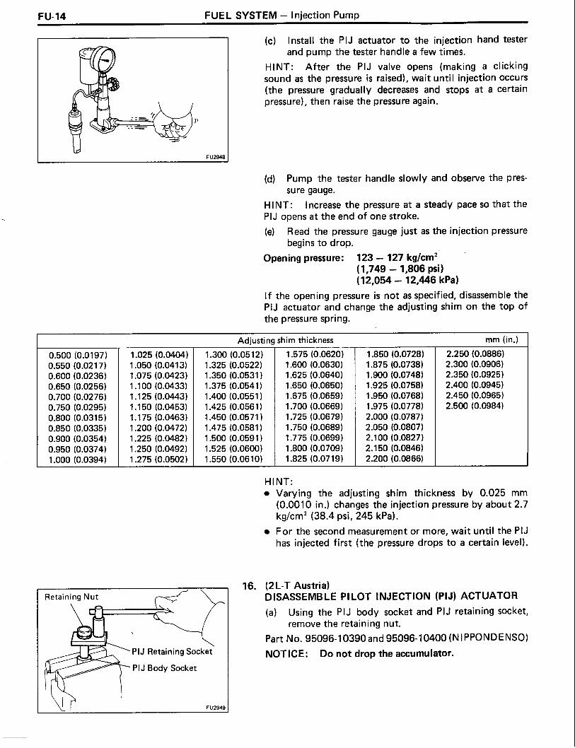
FU-14 FUEL SYSTEM - Injection Pump
(c) Install the PIJ actuator to the injection hand tester and pump the tester handle a few times.
HINT: After the PIJ valve opens (making a clicking sound as the pressure is raised), wait until injection occurs (the pressure gradually decreases and stops a t a certain pressure), then raise the pressure again.
(d) Pump the tester handle slowly and observe the pres- sure gauge.
HINT: Increase the pressure a t a steady pace so that the PIJ opens a t the end of one stroke.
(e) Read the pressure gauge just as the injection pressure begins to drop.
Opening pressure: 123 - 127 kg/cm2 ( 1,749 - 1,806 psi 1 (1 2,054 - 12,446 kPa)
I f the opening pressure is not as specified, disassemble the PIJ actuator and change the adjusting shim on the top of the pressure spring.
mm (in.) I Adjustin!
1 .025 (0.0404) 1.300 (0.051 2) 1.050 (0.0413) 1
PIJ Retaining Sock
PIJ Body Socket
FU2949
,him thickness
1.575 (0.0620) 1 .SO0 (0.0630) 1.625 (0.0640) 1.650 (0.0650) 1.675 (0.0659) 1.700 (0.0669) 1.725 (0.0679) 1.750 (0.0689) 1.775 (0.0699) 1.800 (0.0709) 1.825 (0.0719)
HINT: Varying the adjusting shim thickness by 0.025 mm (0.0010 in.) changes the injection pressure by about 2.7 kg/cm2 (38.4 psi, 245 kPa).
For the second measurement or more, wait until the PIJ has injected first (the pressure drops to a certain level).
16. (2L-T Austria) DISASSEMBLE PILOT INJECTION (PIJ) ACTUATOR
(a) Using the PIJ body socket and PIJ retaining socket, remove the retaining nut.
Part No. 95096-1 0390 and 95096-10400 (N 1 PPONDENSO)
NOTICE: Do not drop the accumulator.

FUEL SYSTEM - Injection Pump FU-15
(b) Remove the following parts from the holder body. a
(1) Accumulator assembly (2) Distance piece (3) Pressure pin (4) Pressure spring (5) Adjusting shim (for opening pressure) (6) Stopper (7) Adjusting shim (for piston l i f t gap)
HINT: The shims in (5) and (7) are the same shape so keep them separate to distinguish between them.
INSPECTION OF INJECTION PUMP COMPONENTS
INSPECT SPRING LENGTH
Using vernier calipers, measure the free length of each spring.
Spring free length: Delivery valve spring 24.4 mm (0.961 in.) Plunger spring 30.0 mm (1.181 in.) Coupling spring 16.0 mm (0.630 in.) Pneumatic bellows spring (w l HAC)
35.0 mm (1.378 in.) Boost compensator main spring
2L-T (Austria) 24.1 mm (0.949 in.) 2L-T (Others) 19.4 mm (0.764 in.)
Boost compensator sub spring (2L-T Austria) 22.3 mm (0.878 in.)
I f the free length is not as specified, replace the spring(s).
(2L-T Austria) INSPECT ACCUMULATOR ASSEMBLY
(a) Wash the accumulator in clean diesel oil.
NOTICE: Do not touch the accumulator mating surfaces with your fingers.
(b) Tilt the accumulator guide about 60 degrees and pull the piston out about one third of i t s length.
(c) When released, the piston should sink down into the guide vent smoothly by i t s own weight.
(d) Repeat this test, rotating the piston slightly each time.
I f the piston does not sink freely, replace the accumulator assembly.

FU-16 FUEL SYSTEM - Injection P u m ~
ASSEMBLY OF INJECTION PUMP (See pages FU-6 to 8)
1. ADJUST PLUNGER SPRING SHIM
(a) Install the following parts to the distributive head:
(1) Two plunger spring guides
(2) Two upper spring seats
(3) Two plunger springs
(4) Lower spring seat
(5) Upper plunger plate
(6) Lower plunger plate
(7) Pump plunger
HINT: Do not assemble the plunger spring shims a t this time.
(b) Using vernier capliers, measure clearance A indicated in the illustration.
(c) Determine the plunger spring shim size by using the following formula and chart.
2L-T (Austria) New plunger spring shim thickness = 6.1 - A
2L-T (Others) and 3L New plunger spring shim thickness = 5.9 - A
A ... Measured plunger position
Plunger spring shim selection chart for 2L-T (Austria) rnrn (in.)
Measured Shim Measured Shim clearance thickness clearance thickness
More than 3.6 - 3.8 4.6 (0.181) .5 (0.059) (0.142 - 0.150) 2.5 (0.098)
4.1 - 4.2 Less than (0.1 61 - 0.1 65) 2.0 (0.079) 3.2 (0.126) 3.0 (0.1 18)
Plunger spring shim selection chart for 2L-T (Others) and 3L
More than 4.3 - 4.5 1 5.3 (0.209) 7 0.5(0.020) 1 (0.169-0.1771 1 1.5 (0.059) 1
rnrn (in.)
HINT: For a measurement between listed sizes, use the next larger size. Ex. If thickness is 1.1 mm (0.043 in.) by calculation, use a 1.2 mm (0.047 in.) shim.
Shim thickness
4.8 - 4.9 Less than (0.189 - 1.193) 1 .O (0.039) 3.9 (0.154)
Select two shims which have the same thickness.
Measured clearance
Measured clearance
2.0 (0.079)
Shim thickness
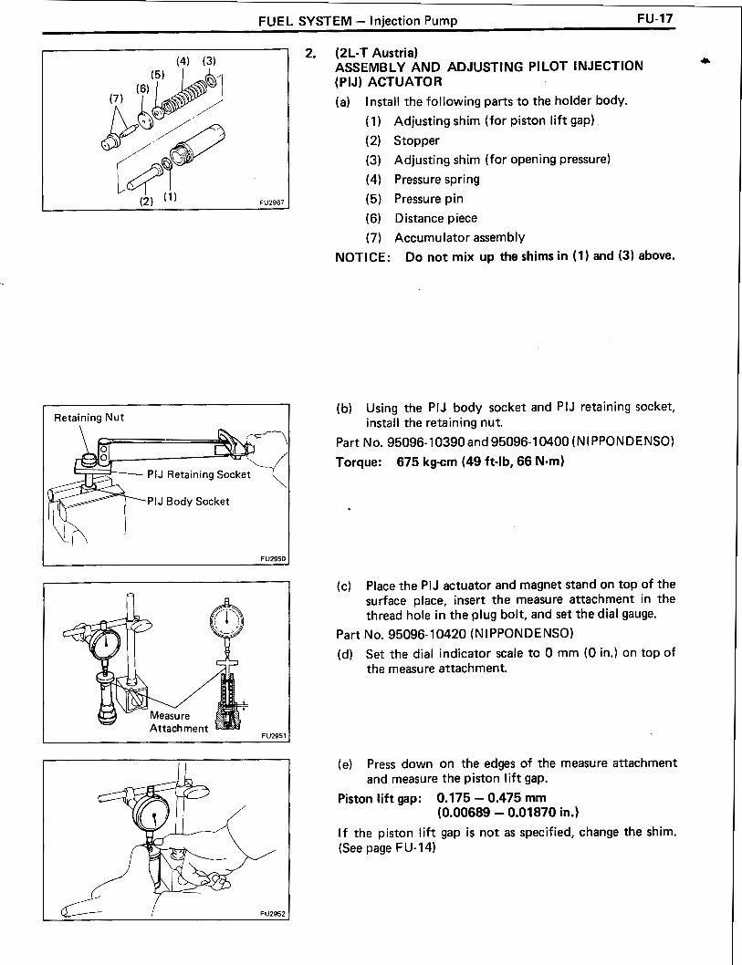
FUEL SYSTEM - Injection Pump FU-17
Retaining N u t
PIJ Retaining Socket
*PIJ Body Socket
2. (2L-T Austria) ASSEMBLY AND ADJUSTING PI LOT INJECTION (PIJ) ACTUATOR
(a) Install the following parts to the holder body.
(1) Adjusting shim (for piston lift gap) (2) Stopper
(3) Adjusting shim (for opening pressure)
(4) Pressure spring
(5) Pressure pin
(6) Distance piece
(7) Accumulator assembly
NOTICE: Do not mix up the shims in (1) and (3) above.
(b) Using the PIJ body socket and PIJ retaining socket, install the retaining nut.
Part No. 95096-10390 and 95096-10400 (NI PPONDENSO)
Torque: 675 kg-cm (49 ft-lb, 66 N-m)
(c) Place the PIJ actuator and magnet stand on top of the surface place, insert the measure attachment in the thread hole in the plug bolt, and set the dial gauge.
Part No. 95096-10420 (NI PPONDENSO)
(d) Set the dial indicator scale to 0 mm (0 in.) on top of the measure attachment.
(e) Press down on the edges of the measure attachment and measure the piston lift gap.
Piston l i f t gap: 0.175 - 0.475 mm (0.00689 - 0.01870 in.)
I f the piston lift gap i s not as specified, change the shim. (See page F U- 14)

FU-18 FUEL SYSTEM - Injection Pump
3. (2L-T Austria) CHECK PLUNGER STROKE
NOTICE: Perform this only when overhauling the injec- tion pump itself.
(a) Using SST, install the conventional distributive head plug.
SST 09260-5401 2 (09262-5401 0)
Torque: 700 kg-cm (51 ft-lb, 69 N-m)
(b) Remove the plug bolt from the distributive head plug and gasket of the injection pump.
(c) Install SST (plunger stroke measuring tool) and a dial indicator to the plug bolt hole of distributive head plug.
SST 09275-5401 0
(d) Install the marking guide to the drive shaft, align the plunger with lower dead center and set the dial indi- cator a t 0 mm (0 in.).
Part No. 95096- 10430 (N I PPON DENSO)
(e) Rotate the drive shaft in the pump rotation direction and use a punch to engrave the flange when the plunger l ift (plunger stroke) is a t maximum valve.
Part No. 95096-10440 (NI PPONDENSO)
Plunger stroke: 0.60 - 0.80 mm (0.0236 - 0.0315 in.)
NOTICE: I f the old mark and new mark are located in different positions, file off the old mark.
(f) Using SST, remove the distributive head plug.
SST 09260-5401 2 (09262-5401 0)
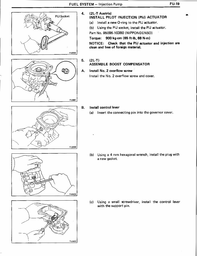
FUEL SYSTEM - Injection Pump FU-19
(2L-T Austria) a INSTALL PI LOT INJECTION (PIJ) ACTUATOR
(a) Install a new O-ring to the PIJ actuator.
(b) Using the PIJ socket, install the PIJ actuator.
Part No. 95096-10380 (NIPPONDENSO)
Torque: 900 kgcm (65 ft-lb, 88 Nm)
NOTICE: Check that the PIJ actuator and injection are clean and free of foreign material.
(2 L-T) ASSEMBLE BOOST COMPENSATOR
lnstall No. 2 overflow screw
Install the No..2 overflow screw and cover.
Install control lever
(a) Insert the connecting pin into the governor cover.
(b) Using a 4 mrn hexagonal wrench, install the plug with a new gasket.
(c) Using a small screwdriver, install the control lever with the support pin.

FU-20 FUEL SYSTEM - Injection Pump
I Attachment Measure
Control Lever
(d) Using a 4 mm hexagonal wrench, install two new gas- kets and the two bolts.
Install guide bus
Install boost compensator diaphragm
(a) Install the attachment measure to the governor cover.
Part No. 95096-10330 (Nl PPONDENSO)
(b) Measure the distance between the end surface of the control lever and the attachment measure.
(1) l nstall the shim and diaphragm.
HINT: Do not assemble the spring.
(2) With the push rod against the @ surface (flat part), measure dimension "L2" with vernier calipers as shown.
Dimension "L2": Austria Approx. 10.75 mm (0.4232 in.) Others Approx. 10.39 mm (0.4091 in.)
HINT: Dimension "L1" of attachment measure is 10 mm (0.39 in.).

FUEL SYSTEM - Injection Pump FU-21
(3) With the push rod pushed in to the maximum, measure dimension "L3" with vernier calipers as shown. Select shim A to adjust "A L1" obtained as the difference between "L3" and "L2" obtained in (2) above.
Difference "A L1": Austria 0.67 - 0.97 mm (0.0264 - 0.0382 in.) Others 1.23 - 1.33 mm (0.0484 - 0.0524 in.)
Adjusting shim thickness: 1.1 mm (0.043 in. 1.3 mm (0.051 in. 1.5 mm (0.059 in. 1.7 mm (0.067 in. 1.9 mm (0.075 in. 2.1 mm (0.083 in. 2.3 mm (0.090 in. 2.5 mm (0.098 in. 2.7 mm (0.106 in. 2.9 mm (0.1 14 in. 3.1 mm (0.122 in. 3.3 mm (0.130 in.
(4) Remove the diaphragm and push rod.
(c) Insert 1.5 - 2.5 cc (0.09 - 0.15 cu in.) of engine oil into the bushing hole.
(d) Install the following parts:
(1) Boost compensator shim A
(2) Main spring
(3) Diaphragm and push rod
(4) Sub spring (Austria only)
(5) Boost compensator shim B (Austria only)
(e) Using a 5 mm hexagonal wrench, install the four bolts and governor cover.

F U-22 FUEL SYSTEM - lniection P u m ~
Austria
Others
(f) Measure the distance between the control lever end surface and the attachment measure.
(Austria) ( 1 ) Measure dimension "L4" with vernier calipers
as shown. Adjust the difference "AL2" between "L2" measured in (b) and "L4" by rotating the guide bushing.
Difference "A L2": 1.30 - 1 .SO mm (0.0512 - 0.0591 in.)
(2) Apply 350 mmHg (13.8 in.Hg, 46.7 kPa) of ab- solute pressure to the boost compensator and measure dimension "L5" with vernier calipers as -shown. Select shim B to adjust "AL3" obtained as the difference between "L5" and "L2" measured in (b).
Difference "A L3": 1.70 - 1.94 mm (0.0669 - 0.0764 in.)
Adjusting shim thickness: 12.90 mm (0.508 in.) 13.15 mm (0.518 in.) 13.40 mm (0.528 in.)
( 0 thers) Apply 0.27 kg/cm2 (3.8 psi, 26 kPa) of pressure to the boost compensator and measure dimension "L4" with vernier calipers as shown. Adjust "L4" by rotating the guide bushing.
Dimension "LC: 9.85 - 9.95 mm (0.3878 - 0.3917 in.)
(g) Remove the attachment measure.
Part No. 95096 - 10030 (NI PPONDENSO)

FUEL SYSTEM - Injection Pump FU-23
6. INSTALL ADJUSTING LEVER SHAFT TO GOVERNOR a SHAFT Install the following parts to the governor cover:
(1) Plate washer
(2) New O-ring
(3) Adjusting lever shaft, O-ring and plate washer assembly
7. INSTALL GOVERNOR COVER
(a) Install a new gasket to the groove of the governor cover.
(b) (2L-T) Connect the adjusting lever shaft to the governor link and twist the shaft lightly.
(c) (3L) Install the speed control spring to the adjusting lever shaft.
(dl (3L) l nstall the damper spring and spring seat, and connect the speed control spring to the spring seat.
(e) Using a 5 mm hexagonal wrench, install the governor cover with the four bolts.
Torque: 85 kg-cm (74 in.-lb, 8.3 N-m)
HINT: Use the bolt which is 35 mm (1.38 in.) length.
(f) (2L-T and w/ HAC) lnstall the idle speed adjusting screw.
8. INSTALL ADJUSTING LEVER
(a) Place the return spring on the governor cover.

FU-24 FUEL SYSTEM - Injection Pump
(b) Hook the return spring to the adjusting lever, and turn and place the adjusting lever on the governor shaft.
(c) Align the lines of the adjusting lever shaft and adjust- ing lever.
(dl lnstall the adjusting lever with the nut.
9. INSTALL FUEL CUT SOLENOID
(a) lnstall a new O-ring on the fuel cut solenoid.
(b) lnstall the strainer, valve, spring, a new gasket and the fuel cut solenoid.
Torque: 225 kg-cm (16 ft-lb, 22 N.m)
(c) lnstall the lead wire to the fuel cut solenoid with the nut.
(d) l nstall the dust cover to the fuel cut solenoid.
(e) l nstall the lead wire connector to bracket.
(f) Using a 6 rnm hexagonal wrench, install the con- nector bracket with the bolt.
lo. (2L-T) INSTALL DASH POT
lnstall a new gasket and the dash pot.
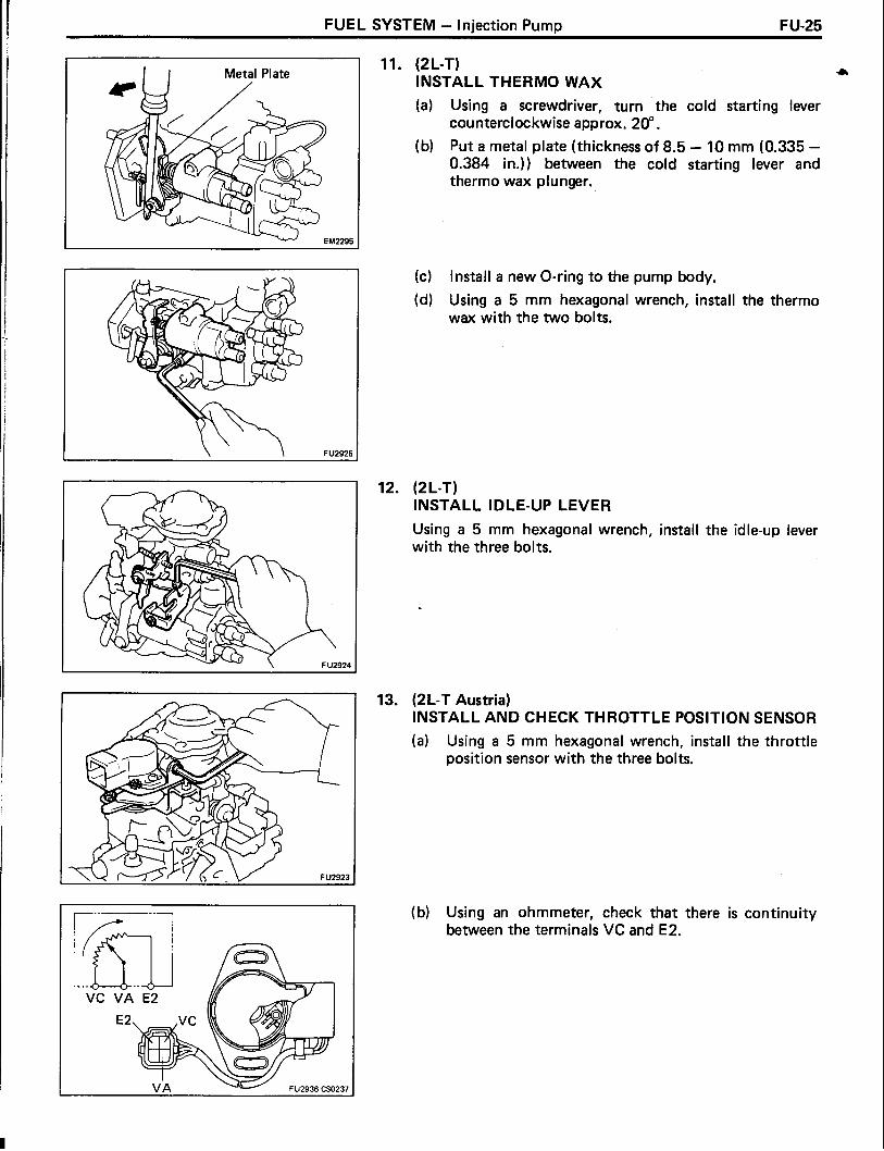
FUEL SYSTEM - Injection Pump FU-25
I I Metal Plate 11. (2L-T)
INSTALL THERMO WAX
(a) Using a screwdriver, turn the cold starting lever counterclockwise approx. 20".
(b) Put a metal plate (thickness of 8.5 - 10 mm (0.335 - 0.384 in.)) between the cold starting lever and thermo wax plunger.
(c) Install a new O-ring to the pump body.
(dl Using a 5 mm hexagonal wrench, install the thermo wax with the two bolts.
12. (2L-T) INSTALL IDLE-UP LEVER
Using a 5 mm hexagonal wrench, install the idle-up lever with the three bolts.
13. (2L-T Austria) INSTALL AND CHECK THROTTLE POSITION SENSOR
(a) Using a 5 mm hexagonal wrench, install the throttle position sensor with the three bolts.
(b) Using an ohmmeter, check that there is continuity between the terminals VC and E2.

FU-26 FUEL SYSTEM - lniection Pump
(c) Using an ohmmeter, measure the resistance between terminals VA and E2.
Resistance: As the opening angle of the adjusting lever increases, the resistance should continue to decrease.
n 1 14. (wl Tachometer) INSTALL PICKUP SENSOR
(a) Install a new O-ring and pickup sensor.
(b) Connect the two lead wires to the connector. Torque: 210 kg-cm (15 ft-lb, 21 N-m)
15. (w/ A/C) INSTALL IDLE-UP ACTUATOR
I 2L-T and w/ HAC
4 7 ~ 3 - 2 - D FU2129
17. PERFORM AIR TIGHT TEST
(a) Install a bolt to the overflow port.
16. REMOVE INJECTION PUMP FROM SST (STAND)
(b) Connect an air hose to the fuel inlet pipe and place the injection pump into diesel fuel.
NOTICE: On vehicles with the throttle position sensor (2L-T Austria), be careful not to immerse sensor in diesel fuel.
(c) Apply 0.5 kg/cm2 (7 psi, 49 kPa) of pressure and con- firm that there are not leaks.
(d) Next check that there are no leaks with 5.0 kg/cm2 (71 psi, 490 kPa) of pressure applied.
18. INSTALL SET KEY OF INJECTION PUMP DRIVE PULLEY ON DRIVE SHAFT
SST 09241 -76022 and 09245-5401 0

FUEL SYSTEM - Injection Pump FU-27
& Fuel In le t Pipe
ADJUSTMENT OF INJECTION PUMP
1. PRE-TEST CHECK AND PREPARATION
(a) The specifications for test nozzle and nozzle holders are as follows.
Test nozzle: DN12SD12 (NIPPONDENSO)
Test nozzle opening pressure: 145 - 155 kglcm? (2,062 - 2,205 psi, 14,220 - 15,200 kPa)
(b) Check the accuracy of the tachometer.
Allowable error: + 40 rpm
(c) l nstall the angle gauge stand.
(d) Mount the injection pump body on the pump tester. HINT: Place a mark on the key groove portion of the coupling.
(e) Install an injection pipe with the following specifica- tions.
Outer diameter: 6.0 mm (0.236 in.) Inner diameter: 2.0 mm (0.079 in.)
Length: 840 mm (33.07 in.)
Minimum bending radius: 25 mm (0.98 in.) or more
( f) Remove the fuel inlet hollow screw.
(g) Connect the fuel inlet pipe with an adapter.

FU-28 FUEL SYSTEM - lniection Pump
I Overflow 1 (h) Install the overflow hose with the overflow screw. HINT: Always use the overflow screw installed on the pump to be adjusted.
(i) Using a 5 mm hexagonal wrench, remove the two bolts and RH timer cover.
(j) Install the inner pressure gauge with the timer measuring device.
Part No. 950%- 10220 and 95095- 1023 1 (NIPPONDENSO)
HINT: Bleed air by the air bleed screw.
(k) (2L-T) Connect SST (turbocharger pressure gauge) to the boost compensator.
SST 09992-00241
Nozzle
SST (2L-T I only)
Overflow Port f \-----,, --1
I I I
Measuring Cylinder (
I
Fuel Feed

FUEL SYSTEM - Injection Pump FU-29
(I) Apply about 6 volts of DC power to the fuel cut sole- * noid.
NOTICE: When applying voltage to the solenoid, position the battery as far away from the solenoid as possible so that a spark does not occur.
When connecting the battery cable, connect the sole- noid side first.
(m) The Dressure for feeding fuel to the injection pump . .
shouid be 0.2 kg/cm2 (2.8 psi, 20 kPa). The fuel tem- perature for pump testing should be 40 - 45°C ( 104
(n) Install an angle gauge to the stand and set it to the adjusting lever.
(0) Secure the adjusting lever fully on the maximum speed side.
(p) Check the installation direction of the camplate as follows:
0 Disconnect the injection pipe from the position marked "C" on the distributive head.
0 Using SST, remove the delivery valve holder.
SST 09260-5401 2 (09269-54020)
Check that fuel is flowing out when the mark is in the position shown in the illustration. I f not, it is improperly assembled.
Disassemble and change the camplate position 180" in the opposite direction.
HINT: At this time, disconnect the fuel cut solenoid wire harness.

FU-30 FUEL SYSTEM - Injection Pump
30 Seconds
1
Using SST, install the delivery valve holder.
SST 09260-5401 2 (0926954020)
Connect the injection pipe.
eed the air from the injec :tion pipes.
(r) Race the injection pump for 5 minutes a t 2,000 rpm.
NOTICE: Check that there is no fuel leakage or abnormal noise.
HINT: 0 Measure the volume of each injection cylinder with a
measuring cylinder.
Before measuring the injection volume, first hold the cylinder tilted for a t least 30 seconds to discard all the fuel.

FUEL SYSTEM - Injection Pump FU-31
2. PRE-SET FULL LOAD INJECTION VOLUME )r
(a) Set the adjusting lever to maximum position.
(b) (2L-T Austria) Apply 0.68 kg/cm2 (9.6 psi, 66 kPa) of pressure to the boost compensator.
(c) (2L-T Others) Apply 0.63 kg/cm2 (9.0 psi, 62 kPa) of pressure to the boost compensator.
(d) Measure the injection volume.
(e) Remove the collar seal as follows:
0 Hold the full load set screw, and release the collar seal from the spot weld by turning the lock nut counterclockwise 90" or more.
Item I Pump rpm / No. of measuring strokes
Using a screwdriver, remove the collar seal.
Injection volume cc icu in.) 1
( f) Adjust by turning the full load set screw.
HINT: The injection volume will increase about 3 cc (0.18 cu in.) with each 1 I 2 turn of the screw.

FU-32 FUEL SYSTEM - lniection Pump
3. (2L-T and w/o HAC) PRE-SETTING OF LOAD SENSING TIMER
Using a 5 mm hexagonal wrench, adjust the protrusion of the governor shaft.
Protrusion: 0.5 - 2.0 mm (0.020 - 0.079 in.)
4. PRE-SET MAXIMUM SPEED
(a) set the adjusting lever to maximum position.
(b) (2L-T Austria) Apply 0.68 kg/cm2 (9.6 psi, 66 kPa) of pressure to the boost compensator.
(c) (2L-T Others) Apply 0.63 kg/cm2 (9.0 psi, 62 kPa) of pressure to the boost compensator.
(d) Measure the injection volume.
Injection volume cc (cu in.)
/ 2L-T
Maximum Speed Adjusting Screw
No. of measuring strokes Item
I 3L
(e) Cut off the seal wire.
(f) Adjust the injection volume with the maximum speed adjusting screw.
Pump rpm
Austria
Others
5. ADJUST PUMP INNER PRESSURE
Hong Kong, Singapore, Malaysia
Others
(a) Measure the pump inner pressure a t the below listed rpm.
2,450
2,400
Pump rpm Inner pressure kg/cm2 (psi, kPa) 1
2,200
2,300
200
200
4.3 - 6.3 (0.26 - 0.38)
4.3 - 6.3 (0.26 - 0.38)
200
200
4.6 - 6.2 (0.28 - 0.38)
4.6 - 6.2 (0.28 - 0.38)

FUEL SYSTEM - lniection Pump FU-38
(b) I f the pressure is low, adjust by lightly tapping the regulator valve piston while watching the pressure gauge.
HINT: I f the pressure i s too high or i f the regulator valve was tapped in too far, the regulator valve must be replaced.
6. CHECK OVERFLOW VOLUME Measure the overflow volume a t the below listed rpm.
HINT: Always use the overflow screw installed on the pump to be adjusted.
Pump rpm
2,200'
7. (2L-T) RELEASE COLD STARTING SYSTEM FOR NEXT INSPECTIONS
Overflow volume cclmin. (cu in.Imin.1
370 - 800 (22.6 - 48.8)
(a) Using a screwdriver, turn the cold starting lever counterclockwise approx. 20".
(b) Put a metal plate (thickness of 8.5 - 10 mm (0.33 - . 0.39 in.)) between the cold starting lever and thermo
wax plunger.
HINT: Keep the cold starting system released until al l measurements and adjustments are finished.
8. ADJUST TIMER
(a) Set the timer measuring device a t zero.
(b) Measure the piston stroke at the below listed rpm.
Piston stroke mrn ( in. )
1.2 - 2.0 (0.047 - 0.079)
2.5 - 3.3 (0.098 - 0.130)
5.4 - 6.0 (0.213 - 0.236)
5.4 - 6.0 (0.213 - 0.236)
1.4 - 2.2 (0.055 - 0.087)
3.0 - 3.8 (0.1 18 - 0.150)
5.5 - 6.3 (0.217 - 0.248)
6.7 - 7.5 (0.264 - 0.295)
0.6 - 1.4 (0.024 - 0.055)
1.8 - 2.6 (0.071 - 0.102)
4.4 - 5.2 (0.1 73 - 0.205)
4.7 - 5.5 (0.185 - 0.217)
Pump rpm
800
1,200
2,000
2,300
800
1,200
1,800
2,300
800
1,200
2,000
2,300
Item
2 L-T
Austria
Others
3L

FU-34 FUEL SYSTEM - lniection P u m ~
Minus 0" Plus Idle Speed A Maximum Speed Side Side
HINT: Check that the hysteresis is within 0.3 mm (0.012 in.).
(c) Using a 5 mm hexagonal wrench, adjust by the timer adjusting screw.
HINT: The stroke will decrease with turn to clockwise and increase with turn to counterclockwise.
(2 L-T) CHECK .AIR TIGHTNESS OF BOOST COMPENSATOR
(a) Apply 1.36 kg/cm2 ( 19.3 psi, 133 kPa) of pressure to the boost compensator.
(b) Measure the time it takes for the pressure to drop to 1.33 kg/cm2 ( 18.9 psi, 130 kPa).
Pressure drop: 10 seconds or more
ADJUST FULL LOAD INJECTION VOLUME
(a) The adjusting lever angle for the adjustment below should be as shown in the illustration.
I Adjusting lever angle I I A (Maximum speed side) I B (Idle speed side) I
--
I Plus 23.5 - 33.5" I Minus 12.5 - 22.5"
(b) (2L-T Austria) Apply 0.68 kg/cm2 (9.6 psi, 66 kPa) of pressure to the boost compensator.
(c) (2L-T Others) Apply 0.63 kg/cm2 (9.0 psi, 62 kPa) of pressure to the boost compensator.
(d) Measure the full load injection volume.
Adjusting lever angle position
I 2L-T
Pump rPm
3 L
Austria
Others
No. of measuring
strokes
Hong Kong, Singapore, Malaysia
Others
Injection volume cc (CU in.)
Plus 23.5 - 33.5"
Plus 23.5 - 33.5'
Plus 23.5 - 33.5"
Plus 23.5 - 33.5'
1,400
1.200
1,200
1,200
200
200
- -
14.04 - 14.36 (0.86 - 0.88)
13.94 - 14.26 (0.85 - 0.87)
200
200
10.96 - 11.28 (0.67 - 0.69)
11.56 - 11.88 (0.71 - 0.72)

FUEL SYSTEM - Injection Pump FU-35
2 L-T
Austria
Others
Hong Kong, Singapore, Malaysia
Others
(e) Adjust by turning the full load set screw.
HINT: The injection volume will increase about 3 cc (0.18 cu in.) with each 112 turn of the screw.
11. ADJUST MAXIMUM SPEED (a) (2L-T Austria)
Apply 0.68 kg/cm2 (9.6 psi, 66 kPa) of pressure to the boost compensator.
(b) (2L-T Others) Apply 0.63 kg/cm2 (9.0 psi, 62 kPa) of pressure to the boost compensator.
(c) Measure the injection volume at each pump rpm.
Adjusting No. of Pump measuring
lnjection volume lever angle Remarks
rpm cc (cu in.) position strokes
4.3 - 6.3 (0.26 - 0.38) Plus
8.3 - 10.5 (0.51 - 0.64) 23.5 - 33.5'
2,750 1.3 (0.8) or less
Plus 1
7.1 - 9.3 (0.43 - 0.57 - 23.5 - 33.5O - - -
2,750 1.3 (0.8) or less - 2,200 4.6 - 6.2 (0.28 - 0.38) Adjust
Plus 2,000 200 8.44 - 10.44 (0.52 - 0.64) -
23.5 - 33.5' 2,400 1.3 (0.8) or less - 2,300 4.6 - 6.2 (0.28 - 0.38) Adjust
Plus 2,100 200 9.08 - 11.08 (0.55 - 0.68) -
23.5 - 33.5" 2,550 1.3 (0.8) or less -
Maximum Speed Adjusting Screw (d) Adjust by turning the maximum speed adjusting screw.

FU-36 FUEL SYSTEM - Injection Pump
&sleeve Plug
@- E- Ring FU1814
Head Thickness
@-sleeve Plug
If the injection volume at 100 rpm is not as specified, re- place the governor sleeve plug as follows:
Using SST and a press, press out the sleeve plug assembly from the governor sleeve.
SST 09236-001 01 (09237-00070)
Remove the E-ring and following parts from the sleeve plug:
(1) Stop ring
(2) Bearing and two bearing retainers
Measure the head thickness of the sleeve plug, and select a new sleeve plug.
I Sleeve plug head thickness mrn (in.) I
HINT: Lengthening the plug 0.1 mm (0.004 in.) will in- crease injection volume by 0.6 cc (0.04 cu in.).
Install the following parts to the new sleeve plug with a new E-ring:
(1) Bearing and two retainers
(2) Stop ring
(2L-T) CHECK AND ADJUST FULL LOAD MINIMUM INJECTION VOLUME
(a) (Austria) Using the hand-help vacuum pump, apply 200 mmHg of (7.9 in.Hg, 26.7 kPa) absolute pressure to the boost compensator.

FUEL SYSTEM - Injection Pump F U -37
(b) Measure the injection volume * No. of
measuring strokes
1 500 1 200 1 10.6 - 11.4 1 Others (0.65 - 0.70)
l njection volume
cc (CU in.)
(c) (Austria) I f the injection volume is not as specified, adjust by using shim B. (See page F U-22)
(d) (Others) Using a 3 mm hexagonal wrench, adjust the timer slide stopper.
Austria
(2 L-T) ADJUST BOOST COMPENSATOR CHARACTERISTIC
(Others) (a) Apply pressure to the boost compensator.
(b) Measure the injection volume bushing.
200 1,400 8.8 - 10.0
10.54 - 0.6 1
(c) Using a screwdriver, adjust the guide bushing.
HINT: When the guide bushing is turned clockwise, as seen from above, the injection volume will increase.
Item
Austria
Others
Pump rPm
500
1,200
Boost pressure kg/cm2 (psi, !Pa)
0 (0, 0)
0.41 (5.9, 40)
No. of measuring strokes
200
200
lnjection volume cc (cu in.)
10.8 - 1 1.6 (0.65 - 0.71 1
12.9 - 13.5 (0.79 - 0.82)

F U-38 FUEL SYSTEM - Injection Pump
14. (2L-T) INSPECT AND ADJUST BOOST COMPENSATOR CHARACTERISTIC TENDENCY
(a) Apply pressure to the boost compensator. (b) Measure injection volume.
Austria Others
Pump rpm -
3 - 0 > C 0 ~~ .- 4- o Boost Pressure - Q .- C
(a) Adjust full-load injection (d) Adjust boost compensator volume characteristic
(b) Adjust full-load minimum (e) Adjust boost compensator injection volume characteristic tendency
(c) Adjust.cold starting injection volume F U Z ~ ~ ? 67012
FU2973 68899
1 Austria I 500 1 0.41 (5.9,40) 1 200 1 14.6 - 15.4 (0.89 - 0.93) 1 I I I I
Others 1,200 0.14 (1.9, 13) 200 1 1.2 - 12.0 (0.68 - 0.73) I
Item
la- Sub Spring
-
Boost pressure kg/cm2 (psi, kPa)
Pump rpm
(c) (Austria) I f the injection volume is not as specified, replace the sub spring of the boost compensator with one with different spring constant.
Spring constant: 1.2 kglcm (1 .O4 Iblin.) 1.4 kglcm (1.22 Iblin.)
No. of measuring strokes
Injection volume cc (cu in.)

I
FUEL SYSTEM - Injection Pump FU-39
15. (2L-T) CHECK HYSTERESIS (Austria) Compare the injection volume when the boost compensa- tor pressure is lowered from 0.74 kg/cm2 (10.5 psi, 73 kPa) to 0 kg/cm2 (0 psi, 0 kPa) and, conversely, when it is raised from zero.
(Others) Compare the injection volume when the boost compensa- tor pressure is lowered from 0.78 kg/crn2 (1 1.1 psi, 77 kPa) to 0.14 kg/cm2 (2.0 psi, 14 kPa) and, conversely, when it i s raised from zero.
HINT: Make measurements after moving the adjusting lever between idle and maximum three times for each lowering of the pressure.
Boost pressure kg/cm2 (psi, kPa)
No. of measuring
strokes
Injection volume cc (CU in.)
Hysteresis cc (cu in.)
the load sensing timer End point of the
Austria
Others
load sensing timer
Idle Speed , Maximum Side Speed Side
Adjusting Lever Position ~ ~ 2 3 1 7 FU0251
1,400
1,400
500
500
1,200
1,200
1,200
1,200
I f not within standard value, check each sliding part of the boost compensator and check whether or not there is any oil.
16. (2L-T and w/o HAC) ADJUST LOAD SENSING TIMER
0.74 (10.5, 73)
0.68 (9.6,66)
0.41 (5.9,40)
O (0, 0)
0.74 (10.5,73)
0.63 (9.0, 62)
0.41(5.9,40)
0.14(2.0,14)
(a) Using a 5 mm hexagonal wrench, adjust the starting and end points of the load sensing timer by turning the governor shaft.
(b) Measure the injection volume.
2 00
200
I Maximum speed side I 1,200 1 200 1
13.84 - 14.36 (0.84 - 0.88)
13.94 - 14.26 (0.85 - 0.87)
14.60 - 15.40 (0.89 - 0.94)
10.80 - 11.60 (0.66 - 0.71 )
13.84 - 14.36 (0.84 - 0.88)
13.94 - 14.26 (0.85 - 0.87)
12.90 - 13.50 (0.79 - 0.82)
1 1.20 - 12.00 (0.68 - 0.73)
- -
0.3 (0.02) or less
- - -
0.3 (0.02) or less
-
No. of measuring
strokes
Adjusting lever position
Pump rpm

FI LAO FUEL SYSTEM - lniection P u m ~
(e) Slowly move the adjusting lever from the maximum speed side to the idle speed side, and secure it a t the point where the pump inner pressure begins to drop.
( f ) Measure the injection volume a t the drop point (start- ing point).
No. of 1 e m 1 Pump rpm 1 mzz-;g 1 Injection volume mm (cu in.)
Measured value at step I 2 L - T 1,200 1 200 1 (b) minus 0.6 (0.04) 2
0.4 (0.02)
Measured value a t step / 3 L 1,200 1 200 1 (b) minus 1.0 (0.06) 2
0.4 (0.02)
(g) Using a 5 mm hexagonal wrench, adjust the load sensing timer by turning the governor shaft, and per- form the measurement again as specified.
HINT: The injection volume will increase approx. 3 cc (0.2 cu in.) with each 112 turn of the governor shaft.
(h) Check the end point injection volume by slowly mov- ing the adjusting lever from the maximum speed side to the idle speed side, and secure it a t the point where the pump inner pressure stops dropping.
No. of l njection Pump measuring volume I I strokes 1 cc (cu in.)
3 L
(i) Check the timer piston fluctuation when the adjust- ing lever is moved from the maximum speed side to the idle speed side.
Hong Kong, Singapore, Malaysia
Others
3 L
Timer piston fluctuation mm (in.) l tem
1,200 1 0.62 - 1.02 (0.024 - 0.040)
l f200
r200
Pump rpm
(j) Check the protrusion of the governor shaft.
Protrusion: 0.5 - 2.0 mm (0.020 - 0.079 in.)
200
200
8.12 - 8.52 (0.50 - 0.52)
8.72 - 9.12 (0.52 - 0.56)

FUEL SYSTEM - Injection Pump FU-41
17. CHECK INJECTION VOLUME a
(a) (2L-T Austria) Apply 0.68 kg/cm2 (9.6 psi, 66 kPa) of pressure to the boost compensator.
(b) (2L-T Others) Apply 0.63 kg/cm2 (9.0 psi, 62 kPa) of pressure to the boost compensator.
(c) Measure the injection volume for each pump rpm.
2 L-T
I tern
Austria
Others
Hong Kong, Singapore, Malaysia
Others
Adjusting No. of 1 1 measuring lever angle position strokes
Plus 23.5 - 33.5"
I 1.200 1 200
Plus 23.5 - 33.5"
200
Plus 23.5 - 33..
2oo
Variation Injection volume
limit Remarks cc (cu in.)
cc (CU in.)
13.94 - 14.26 0.4 Basic full-load (0.85 - 0.87 ) (0.02) injection volume
13.60 - 18.40 1.2 Volume during (0.83 - 1.12) (0.07) starting
13.70 - 15.10 0.5 - (0.84 - 0.92) (0.03)
12.30 - 13.70 0.5 - (0.75 - 0.84) (0.03)
1 1.60 - 12.80 0.5 - (0.7 1 - 0.78) (0.03)
13.94 - 14.26 0.4 Basic full-load (0.85 - 0.87) (0.02) injection volume
13.60 - 18.40 1.2 Volume during (0.83 - 1.12) (0.07) starting
12.10 - 13.10 0.5 - (0.74 - 0.80) (0.03)
10.96 - 11.28 0.4 Basic full-load (0.67 - 0.69) (0.02) injection volume
11.60- 16.40 1.2 Volume during (0.71 - 1 .OO) (0.07 starting
9.64 - 1 1.04 0.5 - (0.59 - 0.67) (0.03)
9.39 - 10.69 0.5 - (0.57 - 0.65 (0.03)
11.56- 11.88 0.4 Basic full-load (0.71 - 0.72) (0.02) injection volume
1 1.60 - 1 6.40 1.2 Volume during (0.71 - 1 .OO) (0.07) starting

FU-42 FUEL SYSTEM - Injection Pump
\ \!u--- Dash Pot
18. ADJUST IDLE SPEED
(a) (2L-T) Using pliers, remove the dash pot cover.
l tem
(b) (2L-T) Fully loosen the dash pot adjusting screw.
2 L-T
(c) Measure the injection volume for each pump rpm.
Austria
Others
3L
Adjusting lever angle
position
Minus 12.5 - 22.5' 1 200
Variation Injection volume
limit Remark cc (cu in.)
cc (cu in.)
Pump rpm
- - --
200
2 00
- Minus 13.5 - 21.5'
Minus 13.5-21.5'
q plus 0.5 (0.03) or more - -
q minus 1.1 -2.1 (0.07 -0.13) - -
No. of measuring
strokes
375
350
450
375
, 350
450
q plus 0.5 (0.03) or more 1 - 1 - q minus 0.7 - 1.7 (0.04 - 0.10) 1 - 1 - 1.8 - 2.8 (0.1 1 - 0.17) 1 0.34 (0.02) 1 Adjust
1.2 (0.07) or less
(d) Adjust by turning the idle speed adjusting screw.

.a --- - FUEL SYSTEM - Injection Pump FU-43
\ \-Dash Pot
Set the adjusting lever to the angle for the injection volume shown below.
Pump No. of lnjection volume I Item 1 rpm 1 mzzi:g 1 cc (cu in.'
I Others 1 600 1 200 1 q = 0.6 - 0.8 (0.04 - 0.05) 1
- -
f (2L-T) Adjust the injection volume with the dash pot adjust- ing screw.
Austria
HINT: The stroke will decrease with turn to clockwise and increase with turn to counterclockwise.
Pump No. of lnjection volume I Item 1 rpm 1 g 1 cc (cu in.)
600 200 I q = 0.5 - 0.7 (0.03 - 0.04)
(9) (2L-T) Readjust by turning the idle speed adjusting screw.
Austria
Others
600
600
(h) (2L-T) l nstall the dash pot cover.
Item
(2 L-T) ADJUST COLD STARTING SYSTEM
(a) Remove the overflow screw and check the fuel tem- perature in the fuel pump.
Fuel temperature: 15 - 35" C (59 - 95" F)
(b) Set the set key of the pump drive shaft in a vertical or horizontal position.
(c) Set the scale of the timer measuring device to zero.
(d) Check the adjusting lever opening angle and consider this angle as zero.
200
200
pump rpm
lever angle position
0.34 (0.02)
0.34 10.02)
'
q plus 0.2 - 0.4 (0.01 - 0.02)
q plus 0.2 - 0.4 (0.01 - 0.02)
lnjection volume cc (CU in.)
Austria
Others
Variation limit
cc in.,
Minus 13.5 - 2 1.5"
Minus 13.5 - 2 1.6"
375
375
3.0 - 4.0 (0.18 - 0.24)
1.8 - 2.8 (0.1 1 - 0.171

FU-44 FUEL SYSTEM - lniection Pumo
I I Metal Plate
I I Austria Others
L
E" -20 0 20 40 -20 0 20 40 (-4)(32) (68)(104) (-4)' (32) (68) (104)
F Fuel Temperature "C (OF) FV2975
I Timer Adjusting Screw
(e) Remove the metal plate between the cold starting lever and thermo wax plunger.
(f) Torque the cold starting lever clockwise to approx. 50. kg-cm (43 in.-lb, 4.9 N-m) and keep the lever tightened for about 10 seconds. Then release the torque.
(g) Measure the timer piston stroke.
1 Item I Timer piston stroke Fuel temperature
mm (in.)
(h) Adjust by turning the timer adjusting screw.
HINT: Screw in for stroke decrease.
Austria
Others
20. (2L-T) ADJUST FAST IDLE
(a) Measure the clearance between the adjusting lever and idle speed adjusting screw.
25°C ( 7 7 " ~ )
2 5 " ~ (77°F)
0.7 - 0.9 (0.028 - 0.035)
1.3 - 1.5 (0.051 - 0.059)
I 20°C ( 68°F) I 2.5 rnm (0.098 in.) 1 Fuel temperature Clearance 1
5 0 " ~ (122°F) 0 mm (0 in.)
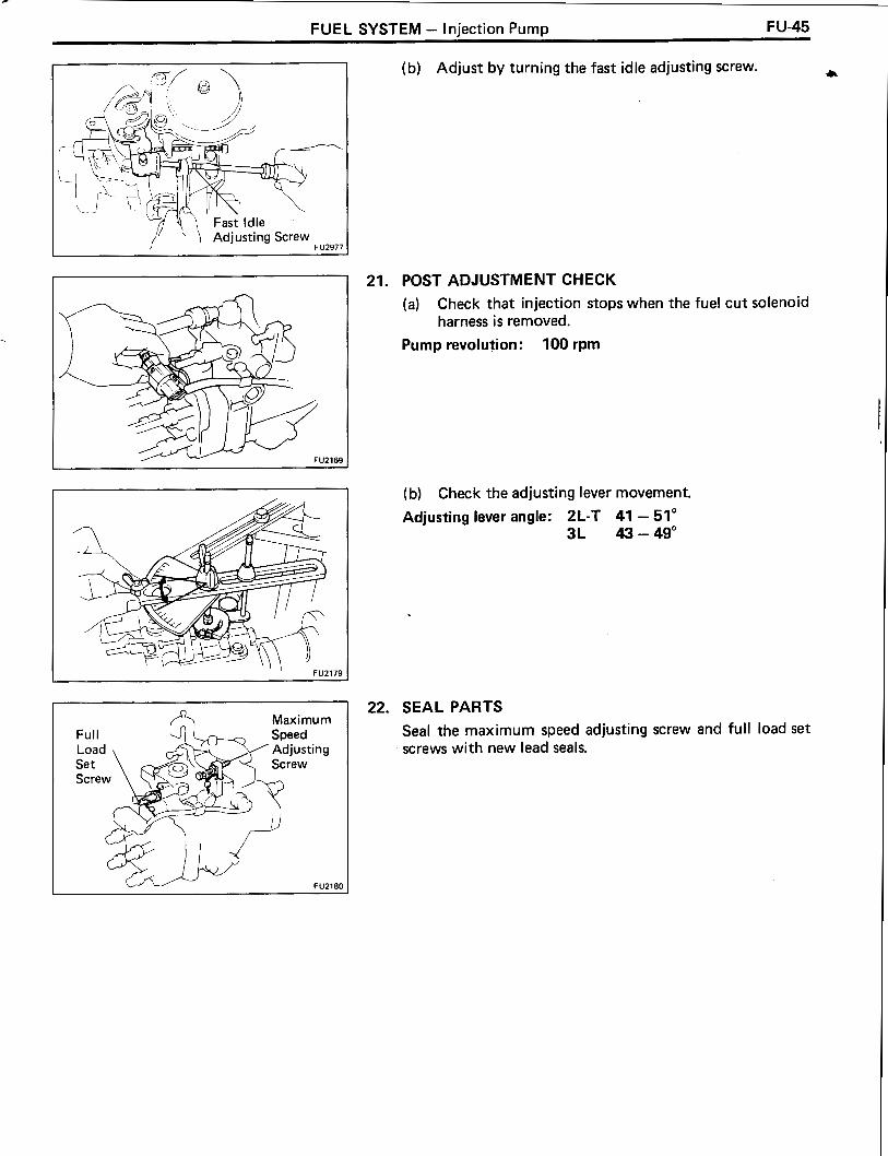
FUEL SYSTEM - Injection Pump FU-45
(b) Adjust by turning the fast idle adjusting screw. 4
, 21. POST ADJUSTMENT CHECK
(a) Check that injection stops when the fuel cut solenoid harness i s removed.
Pump revolution: 100 rpm
(b) Check the adjusting lever movement.
Adjusting lever angle: 2L-T 41 - 51" 3L 43 - 49"
22. SEAL PARTS
Seal the maximum speed adjusting screw and full load set screws with new lead seals.

FU-46 FUEL SYSTEM - Injection Pump
INSTALLATION OF INJECTION PUMP (See page FU-3)
NOTICE: Do not put the injection pump (2L-T and w l HAC) at an angle more than 45" from the horizontal.
1. INSTALL FUEL INLET AND OUTLET PIPES TO INJECTION PUMP
Torque: 250 kgcm (18 ft-lb, 25 N-m)
INSTALL INJECTION PUMP
(a) Align the period lines (or matchmarks) of the injec- tion pump and timing belt case.
Pipe
(b) Install the two nuts holding the injection pump to the timing belt case.
Torque: 210 kg-cm (15 ft-lb, 21 N-m)
(c) Install the pump stay with the four bolts.
Torque: 185 kg-cm (13 ft-lb, 18 N-m)
CHECK INJECTION TIMING (See page EM-24 or 25)
INSTALL INJECTION PIPES
(a) Place the two lower clamps on the intake manifold.
(b) I nstall the four injection pipes.
Torque: 250 kpcm (18 ft-lb, 25 N-m)
NOTICE: On vehicles with the PIJ (2L-T Austria), do not interfere with the PIJ actuator with the spanner. Use a 14 mm spanner when tightening the union nut of No. 2 injection pipe.
(c) Secure the injection pipes with the two upper clamps and bolts.

FUEL SYSTEM - lniection P u m ~ FU-47
CONNECT FUEL HOSES TO INJECTION PUMP
CONNECT INJECTION PUMP CONNECTOR(S)
(2 L-T) CONNECT WATER BY-PASS HOSES TO THERMO WAX
(w/ AIC) CONNECT AIC IDLE-UP VACUUM HOSE
(2 L-T) CONNECT BOOST COMPENSATOR HOSE
INSTALL ACCELERATOR LINKAGE
INSTALL INJECTION PUMP DRIVE PULLEY
Torque: 650 kg-cm (47 ft-lb, 64 N.m)
SET NO. 1 CYLINDER TO TDCICOMPRESSION
INSTALL TIMING BELT
CHECK VALVE TIMING
INSTALL NO. 1 TIMING BELT COVER
INSTALL CRANKSHAFT PULLEY
Torque: 1,700 kg-cm (123 ft-lb, 167 N-m)
INSTALL WATER PUMP PULLEY, FLUID COUPLING AND FAN
(2L-T) INSTALL TURBO WATER HOSE
(2 L-T) FILL WITH ENGINE COOLANT (See page CO-5)
START ENGINE AND CHECK FOR FUEL LEAKS
CHECK IDLE SPEED AND MAXIMUM SPEED (See page EM-27)
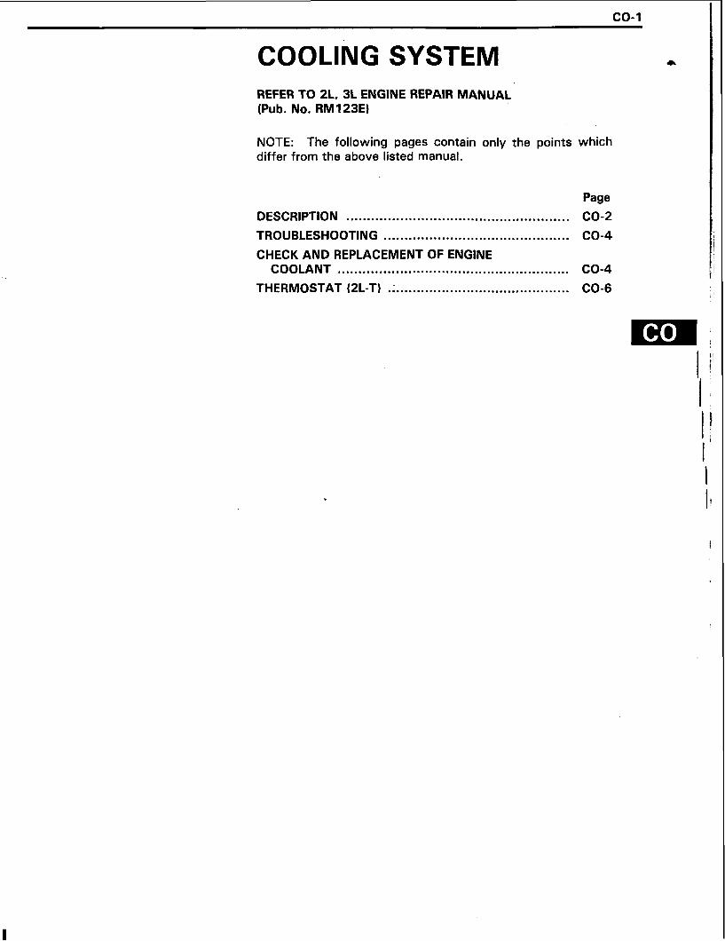
COOLING SYSTEM REFER TO 2L, 3L ENGINE REPAIR MANUAL (Pub. No. RM123E)
NOTE: The following pages contain only the points which differ from the above listed manual.
Page
DESCRIPTION ...................................................... CO-2
TROUBLESHOOTING ............................................. CO-4
CHECK AND REPLACEMENT OF ENGINE COOLANT ........................................................ CO-4
THERMOSTAT (2L-T) .; .......................................... CO-6

CO-2 COOLING SYSTEM - Description
DESCRIPTION This engine utilizes a pressurized water forced circulation cooling system which includes a thermostat equip- ped with a by-pass valve mounted on the inlet side.
2 L-T
- From Heater

COOLING SYSTEM - Description CO -3
The cooling system is composed of the water jacket (inside the cylinder block and cylinder head), radiator, water pump, thermostat, cooling fan, hoses and other components. Coolant which is heated in the water jacket is pumped to the radia- tor, where it is cooled by the cooling fan and the vehicle windstream. Coolant which has been cooled is then sent back to the engine by the water pump, where it cools the engine. The water jacket is a network of channels in the shell of the cylinder block and cylinder head through which coolant passes. It is designed to provide adequate cooling of the cylinders and combustion chambers which become the hottest during engine operation.
RADIATOR The radiator performs the function of cooling
the coolant which has passed through the water jacket and become hot, and it is mounted in the front of the vehicle. The radiator consists of an upper tank and lower tank, and a core which con- nects the two tanks. The upper tank contains an inlet for coolant from the water jacket and a filler inlet. It also has a hose through which excess coolant or steam can flow. The lower tank has an outlet and drain cock for the coolant. The core contains many tubes and cooling fins through which coolant flows from the upper tank to the lower tank so that coolant has been heated up as it passes through the water jacket is cooled here by the air sucked through the radiator by the cool- ing fan, as well as by the wind generated by the. vehicle's travel. Models with an automatic trans- mission include an automatic transmissions fluid cooler built into the lower tank of the radiator.
RADIATOR CAP The radiator cap is a pressure type cap which
seals the radiator, resulting in pressurization of the radiator as the coolant expands. The pressuriza- tion prevents the coolant from boiling even when the coolant temperature exceeds 100" C (21 2" F). A relief valve (pressurization valve) and a vacuum valve (negative pressure valve) are built into the radiator cap. When the pressure generated inside the cooling system exceeds the limit (coolant tem- perature: 1 10 - 1 20°C, 230 - 248" F, pressure; 0.3 - 1.0 kg/cm2, 4.3 - 14.2 psi, 29.4 - 98.1 kPa) the relief valve is opened by the pressure and lets steam escape through the overflow pipe. The vacuum valve opens to allow atmospheric air to enter to alleviate the vacuum which develops in the cooling system after the engine is stopped and the coolant temperature drops. The valve's opening allows the pressure in the cooling system to return to the reservoir tank.
RESERVOIR TANK * The reservoir tank is used to catch coolant
which overflows the cooling system as a result of volumetric expansion when the coolant i s heated. When the cod~ant temperature drops, the coolant in the reservoir tank returns to the radiator, thus keeping the radiator full at a l l times and avoiding needless coolant loss. To find out i f the coolant needs to be replenished, check the reservoir tank level.
WATER PUMP
The water pump is used for forced circulation of coolant through the cooling system. It is mounted on the front of the cylinder block and driven by a drive belt.
THERMOSTAT The thermostat has a wax type by-pass valve and
is mounted in the water outlet housing. The thermostat is a type of automatic valve operated by fluctuations in the coolant temperature. This valve closes when the coolant temperature drops, preventing the circulation of coolant through the radiator and thus permitting the engine to warm up rapidly. The valve opens when the coolant temper- ature has risen, allowing the circulation of coolant. Wax inside the thermostat expands when heated and contracts when cooled. Heating the wax thus generates pressure which overpowers the force of the spring which keeps the valve closed, thus opening the valve. When the wax cools, i ts con- traction causes the force of the spring to take effect once more, closing the valve. The thermo- stat in this engine operates a t a temperature of 88°C (191°F).

CO-4 COOLING SYSTEM -Troubleshooting, Check and Replacement of Engine Coolant
TROUBLESHOOTING Problem
Engine overheats
Possible cause
Fan belt loose or missing
Dirt, leaves or insects on radiator or condenser
Hoses, water pump, thermostat housing, radiator, heater, core plugs or head gasket leakage
Thermostat faulty
Injection timing retarded ,
Fluid coupling faulty
Radiator hose plugged or rotten
Water pump faulty
Radiator plugged or cap faulty
Cylinder head or block cracked or plugged
Remedy
Adjust or replace belts
Clean radiator or condenser
Repair as necessary
Check thermostat
Adjust timing
Replace fluid coupling
Replace hose
Replace water pump
Check radiator
Repair as necessary
Page
CH-3
CO-6
EM-24 or 25
HINT: Removal of the thermostat would have an adverse effect, causing a lowering of cooling efficiency. Do not remove the thermostat, even if the engine tends to overheat.
Radia Drain
CHEC ENGlF
K AND REPLACEMENT OF IE COOLANT
CHECK ENGINE COOLANT LEVEL AT RESERVOIR TANK
The coolant level should be between the "LOW" and "FU LL" lines.
I f low, check for leaks and add coolant up to the "FULL" line.
CHECK ENGINE COOLANT QUALITY
There should not be any excessive deposits of rust or scales around the radiator cap or radiator filler hole, and the coolant should be free from oil.
I f excessively dirty, replace the coolant.
REPLACE ENGINE COOLANT
(a) Remove the radiator cap.
CAUTION: To avoid the danger of being burned, do not remove it while the engine and radiator are s t i l l hot, as fluid and steam can be blown out under pressure.
(b) Drain the coolant from the radiator and engine drain cocks.
(c) Closethedraincocks.
Torque (Engine drain cock): 300 kg-cm (22 ft-lb, 29 N-m)

COOLING SYSTEM - Check and Replacement of Engine Coolant CO-5
(d) Fill the system with coolant. Use a good brand of ethylene-glycol or TOYOTA radiator conditioner or equivalent anticorrosive, mixed according to the manufacturer's directions.
Ethylene-glycol type: This type has an antifreeze and anticorrosive effect. TOYOTA radiator conditioner: This has only an anticor- rosive effect.
NOTICE: Do not use alcohol type coolant.
The coolant should be mixed with demineralized water or distilled water.
Capacity (w/o Heater): LJ 10.0 liters (10.6 US qts, 8.8 Imp. qts) LN 2L-T 8.2 liters (8.7 US qts, 7.2 Imp. qts)
3L 8.1 liters (8.6 US qts, 7.1 Imp. qts)
Capacity (w/ Heater): LJ 10.9 liters (1 1.5 US qts, 9.6 Imp. qts) LN 2L-T 9.1 liters (9.6 US qts, 8.8 Imp. qts)
3L 9.0 liters (9.5 US qts, 7.9 Imp. qts)
Capacity (w/ Front and rear heaters): LJ 2L-T 11.5 liters (12.2 US qts, 10.1 Imp. qts) LN 2L-T 9.4 liters (9.9 US qts, 8.3 Imp. qts)
3L 9.3 liters (9.8 US qts, 8.2 Imp. qts)
(e) Reinstall the radiator cap.
(f) Warm up the engine and check for leaks.
(g) Recheck the coolant level and refill as necessary.

CO-6 COOLING SYSTEM - Thermostat (2L-T)
THERMOSTAT (2L-T) REMOVAL OF THERMOSTAT
1. DRAIN ENGINE COOLANT (See page CO-4)
Valve Lift
C01171
2. REMOVE WATER OUTLET
Remove' the three bolts and water outlet from the water outlet housing.
3. REMOVE THERMOSTAT
INSPECTION OF THERMOSTAT
INSPECT THERMOSTAT
HINT: The thermostat i s numbered with the valve open- ing temperature.
(a) Immerse the thermostat in water and gradually heat the water.
(b) Check the valve opening temperature.
Valve opening temperature: 86 - 90" C (1 87 - 194" F)
I f the valve opening temperature is not as specified, replace the thermostat.
(c) Check the valve lift.
Valve lift: 8 mm (0.31 in.) or more at 100°C (212" F)
If the valve lift is not as specified, replace the thermostat.
(d) Check that the valve spring is tight when the thermo- s ta t is fully closed.
I f necessary, replace the thermostat.

COOLING SYSTEM - Thermostat (2L-T) CO-7
INSTALLATION OF THERMOSTAT .r*
1. PLACE THERMOSTAT IN WATER OUTLET HOUSING
(a) Install a new gasket to the thermostat.
(b) Install the thermostat with the jiggle valve upward.
2. INSTALL WATER OUTLET TO WATER OUTLET HOUSING Install the water outlet with the three bolts.
Torque: 195kg-cm(14ft-lb,19N.m)
3. FILL WITH ENGINE COOLANT (See page CO-5)
4. START ENGINE AND CHECK FOR LEAKS

LUBRICATION SYSTEM
LU- 1
REFER TO 2L, 3L ENGINE REPAIR MANUAL (Pub. No. RM123E)
NOTE: The following pages contain only the points which differ from the above listed manual.
Page
DESCRIPTION ....................................................... LU-2
OIL PRESSURE CHECK ........................................ LU-4
REPLACEMENT OF ENGINE OIL AND OIL FILTER ......................................................... LU-5
OIL COOLER AND RELIEF VALVES (2L-T) ................. LU-7

LU-2 LUBRICATION SYSTEM - Description
DESCRIPTION A fully pressurized, fully filtered lubrication system has been adopted for this engine.
2 L-T
- - - - - - - - - - - - - - - - - - - - - - - - - - - - - I
-1 I
VALVE LIFTERS & I I I C - - - - - - - - - - - - - -- - - - - - -- - I
I
I - - - - - - - - - - - - - - - - - - - - - - CRANK JOURNALS CAMSHAFT OIL HOLE - -4
I I
I I
OIL NOZZLE CAMSHAFT JOURNAL I
I t - 1
I (No. 3) I I
CHECK VALVE
t I
I CYLINDER HEAD -1
I I I
I I I I
MAIN OIL HOLE 1 I I r---------- I
I
TURBOCHARGER I (2L-T only) I
O IL FILTER VACUUM PUMP
I------ ---- I I
I I L - - - - - - -- - I I
I I I I I I OIL STRAINER + I
3 ! t t I I
OIL PAN

LUBRICATION SYSTEM - Description LU-3
A pressure feeding lubrication system has been adopted to supply oil to the moving parts of this engine. The lubrication system consists of an oil pan, oil pump, oil filter and other external parts which supply oil to the moving parts in the engine block. The oil circuit is shown in the illustration a t the top of the previous page. Oil from the oil pan is pumped up by the oil pump. After it passes through the oil filter, it is fed through the various oil holes in the crankshaft and cylinder block. After passing through the cylinder block and per- forming i t s lubricating function, the oil is returned by gravity to the oil pan. A dipstick on the center left side of the cylinder block is provided to check the oil level.
-. OIL PUMP
The oil pump pumps up oil from the oil pan and sends it under pressure to the various parts of the engine. An oil strainer is mounted in front of the inlet to the oil pump to remove impurities. The oil pump itself is a trochoid type pump, which uses a drive rotor and driven rotor inside the pump body. When the drive rotor rotates, the driven rotor rotates in the same direction. The axis of the drive rotor shaft is different from the center of
I the driven rotor, so when both rotors rotate, the space between the two rotors changes. Oil is , drawn in when the space widens and is discharged
I when the space becomes narrow.
I I OIL PRESSURE REGULATOR (RELIEF VALVE)
A t high engine speeds, the oil pump supplies more oil to each part that is necessary. For this reason, an oil pressure regulator which works to prevent oversupply of oil is installed on the oil pump. During normal oil supply, a coil spring and valve keep the by-pass closed, but when too much oil is being supplied, the pressure becomes ex- tremely high, overpowering the force of the spring and opening the valves. This allows the excess oil to flow through the valve and return to the inlet of the oil pump.
OIL FILTER * There are two types of oil filter, a full flow type
and a by-pass element type. A full flow type has a relief valve built into the paper filter element. Particles of metal from wear, airborn dirt, carbon and other impurities can get in the oil during use and could cause accelerated wear or seizing if allowed to circulate through the engine. The oil filter, integrated into the oil line, removes these impurities as the oil passes through it. The filter is mounted outside the engine to simplify replace- ment of the filter element. A relief valve is also included ahead of the filter element to relieve the high oil pressure in case the filter element becomes clogged with impurities. The relief valve opens when the oil pressure overpowers the force of the spring. Oil passing through the relief valve by- passes the oil filter and flows directly into the main oil hole in the engine.

LU-4 LUBRICATION SYSTEM - Oil Pressure Check
I OIL PRESSURE CHECK Recommended Viscosity (SAE) : 1 .
TEMPERATURE RANGE ANTICIPATED BEFORE NEXT OIL CHANGE ': On turbocharged englnsr. never use above O'C I3Z0FI
LU0339 I
I w / Sender Gauge I
Adhesive
CHECK ENGINE OIL QUALITY
Check the oil for deterioration, entry of water, discoloring or thinning.
I f the quality is poor, replace the oil.
(2L-T) Use API grade CD or better and recommended viscosity oil.
(3 L) Use API grade CC, CD or better and recommended viscosity oil.
CHECK ENGINE OIL LEVEL
The oil level should be between the "L" and "F" marks on the dipstick.
I f low, check for leakage and add oil up to "F" mark.
NOTICE: Do not fi l l with engine oil above the "F" mark.
- REMOVE OIL PRESSURE SWITCH OR SENDER GAUGE
HI NT (w l Sender gauge) : Use SST.
SST 09027- 1 2 140
INSTALL OIL PRESSURE GAUGE
WARM UP ENGINE
Allow the engine to reach normal operating temperature.
CHECK OIL PRESSURE
Oil pressure: At idling 0.3 kg/cm2 (4.3 psi, 29 kPa)
or more A t 3,000 rpm 3.0 - 5.5 kg/cm2
(43 - 78 psi, 294 - 539 kPa)
REMOVE OIL PRESSURE GAUGE
REINSTALL OIL PRESSURE SWITCH OR SENDER GAUGE
Apply adhesive to two or three threads.
Adhesive: Part No. 08833-00080, THRE E BOND 1344. LOCTITE 242 or equivalent
START ENGINE AND CHECK FOR LEAKS

LUBRICATION SYSTEM - Replacement of Engine Oil and Oil Filter LU-5
REPLACEMENT OF ENGINE OIL AND +
OIL FILTER CAUTION:
Prolonged and repeated contact with mineral oil will result in the removal of natural fats from the skin, lead- ing to dryness, irritation and dermatitis. In addition, used engine oil contains potentially harmful contami- nants which may cause skin cancer. Adequate means of skin protection and washing facilities should be provid- ed.
Care should be taken, therefore, when changing engine oil, to minimize the frequency and length of time your skin is exposed to used engine oil. Protective clothing and gloves, that cannot be penetrated by oil, should be worn. The skin should be thoroughly washed with soap and water, or use waterless hand cleaner, to remove any used engine oil. Do not use gasoline, thinners, or solvents. In order to preserve the environment, used oil and used oil filters must be disposed of only at designated dis- posal sites.
DRAIN ENGINE OIL
(a) Remove the oil filler cap.
(b) Remove the oil drain plug, and drain the oil into a container.
REPLACE OIL FILTER
(a) Using SST, remove the oil filter.
SST 09228- 10001 (w/ By-pass element type) 09228-4001 1 (Full flow type)
(b) Clean and check the oil filter installation surface.

LU-6 LUBRICATION SYSTEM - Replacement of Ennine Oil and Oil Filter
\ SST 1
(c) Apply clean engine oil to the gasket of a new oil filter.
(dl Lightly screw the oil filter into place, and tighten it until the gasket contacts the seat.
(e l Using SST, tighten it additional 314 turn.
SST 09228- 10001 (w l By-pass element type) 09228-4401 1 (Full flow type)
LU0944
3. FILL WITH ENGINE OIL
(a) Clean and install the oil drain plug with a new gasket.
Torque: 400 kg-cm (29 ft-lb, 39 N-m)
(b) Fill with new engine oil (API grade CC (3L only), CD or better and recommended viscosity oil).
Capacity:
liters (US qts, Imp. qts)
(c) Reinstall the oil filler cap.
4. START ENGINE AND CHECK FOR LEAKS
5. RECHECK ENGINE OIL LEVEL (See page LU-4)
l tem W/ Oil filter change
w/o Oil filter change
Dri fill

LUBRICATION SYSTEM - Oil Cooler and Relief Valves (2L-T) LU-7
OIL COOLER AND RELIEF VALVES *
COMPONENTS
Union Bolt Q-* !3imzy
il Filter Bracket
I Filter Bracket
@ * This valve is used as a dummy plug to
I kg-cm (ft-lb, N.m) 1 : Specified torque prevent oil from flowing to main oil hole.
Non-reusable part * Precoated part L U ~ W
REMOVAL OF OIL COOLER AND RELIEF VALVES
DRAIN ENGINE COOLANT (See page CO-4)
REMOVE TURBOCHARGER (See steps 2 to 7 on pages TC- 10 and 1 1)
CONTROL VALVE ASSEMBLY (See step 11 on page EM-37)
REMOVE EXHAUST MANIFOLD (See step 13 on page EM-38)
REMOVE ALTERNATOR
(LJ) REMOVE UNION BOLT
REMOVE O I L FILTER (See page
(Austria) REMOVE EGR VALVE, PIPE, VALVE ADAPTOR AND
J-5)
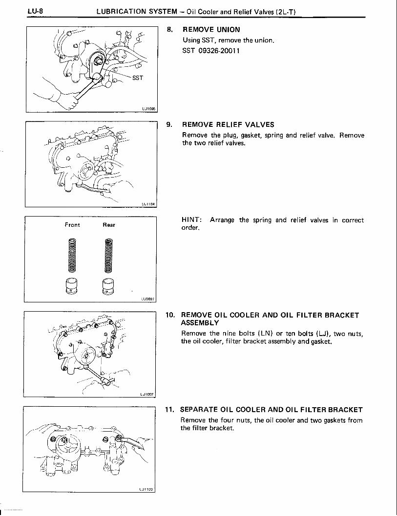
LU-8 LUBRICATION SYSTEM - Oil Cooler and Relief Valves (2L-TI
8. REMOVE UNION
Using SST, remove the union.
SST 09326-2001 1
9. REMOVERELIEFVALVES
Remove the plug, gasket, spring and relief valve. Remove the two relief valves.
Front Rear HINT: Arrange the spring and relief valves in correct order.
10. REMOVE OIL COOLER AND OIL FILTER BRACKET ASSEMBLY
Remove the nine bolts (LN) or ten bolts (LJ), two nuts, the oil cooler, filter bracket assembly and gasket.
11. SEPARATE OIL COOLER AND OIL FILTER BRACKET
Remove the four nuts, the oil cooler and two gaskets from the filter bracket.
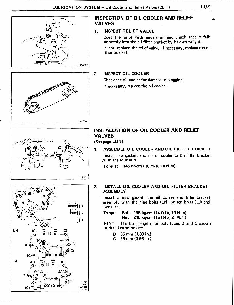
LUBRICATION SYSTEM - Oil Cooler and Relief Valves (2L-T) LU-9
INSPECTION OF OIL COOLER AND RELIEF VALVES
1. INSPECT RELIEF VALVE
Coat the valve with engine oil and check that it falls smoothly into the oil filter bracket by i t s own weight.
I f not, replace the relief valve. I f necessary, replace the oil filter bracket.
2. INSPECT OIL COOLER
Check the oil cooler for damage or clogging.
If necessary, replace the oil cooler.
INSTALLATION OF OIL COOLER AND RELIEF VALVES (See page LU-7)
ASSEMBLE OIL COOLER AND OIL FILTER BRACKET
Install new gaskets and the oil cooler to the filter bracket .with the four nuts.
Torque: 145 kg-cm (10 ft-lb, 14 N-m)
INSTALL OIL COOLER AND OIL FILTER BRACKET ASSEMBLY
Install a new gasket, the oil cooler and filter bracket assembly with the nine bolts (LN) or ten bolts (LJ) and two nuts.
Torque: Bolt 195 kg-cm (14 ft-lb, 19 N.m) Nut 210 kpcm (15 ft-lb, 21 N.m)
HINT: The bolt lengths for bolt types B and C shown in the illustration are:
B 35 mm (1.38 in.) C 25 mm (0.98 in.)

LU- 10 LUBRICATION SYSTEM - Oil Cooler and Relief Valves (2L-T)
INSTALL RELIEF VALVES
Install the relief valve, spring and a new gasket with the plug. Install the two relief valves. Torque: 370 kg-cm (27 ft-lb, 36 N-rn)
INSTALL UNION
(a) Apply adhesive to two or three threads (oil cooler side of the union).
Adhesive: Part No. 08833-00070, THREE BOND 1324 or equivalent
(b) Using SST, install and torque the union.
SST 09326-2001 1
Torque: 430 kg-crn (31 ft-lb, 42 Nm) HINT: Use a torque wrench with a fulcrum length of 300 mm (1 1.81 in.).
INSTALL OIL FILTER (See page LU-5)
(LJ) INSTALL UNION BOLT
(a) Apply adhesive to two or three threads of the union bolt.
Adhesive: Part No. 08833-00070, THREE BOND 1324 or equivalent
(b) Install and torque the union bolt.
Torque: 200 kg-crn (14 ft-lb, 20 Nm)

LUBRICATION SYSTEM - Oil Cooler and Relief Valves (2L-T) LU-11
7. INSTALL ALTERNATOR 3,
Torque : 12 mm head bolt 130 kg-cm (9 ft-lb, 12 N-m) 14 mm head bolt 510 kg-cm (37 ft-lb, 50 N-m)
8. INSPECT DRIVE BELTS (See step 3 on page CH-3)
9. INSTALL EXHAUST MANIFOLD (See step 6 on page EM-43)
10. (Austria) INSTALL EGR VALVE, PIPE, VALVE ADAPTOR AND CONTROLVALVE ASSEMBLY (See step 8 on page EM-44)
11. INSTALL TURBOCHARGER (See steps 3 to 8 on pages TC-13 and 14)
12. FILL WITH ENGINE COOLANT (See page CO-5)
13. START ENGINE AND CHECK FOR LEAKS
14. CHECK ENGINE OIL LEVEL (See page LU-4)

ST- 1
STARTING SYSTEM REFER TO 2L. 3L ENGINE REPAIR MANUAL (Pub. NO. RMl23E)
NOTE: The following pages contain only the points which differ from the above listed manual
Page
.......................................... PRE-HEATING SYSTEM ST-2
...................................... Super Glow Type [2L-TI ST-2 ......................................... Fixed Delay Type [3Ll ST-8
............................................ STARTER RELAY (LJ) ST-9

ST-2 STARTING SYSTEM - Pre-Heating System (Super Glow Type [2L-TI )
PRE-HEATING SYSTEM Super Glow Type [2L-TI SYSTEM CIRCUIT
LJ (Austria)
W (Others)
Starter Switch .
Resistor I: -
Pre-Heating Timer (Emission Control ECU) m Water
Temperature Sensor
AM1 GLOW F L 1.1- 1
ip Battery
# Plug No. Relay CilOw @ Plug No. 1 Relay Glow
E
Resistor F L
Pre-Heating Timer
9 Glow Plug
d 9 , To Alternator 7 Terminal L
Water Temperature Sensor

STARTING SYSTEM - Pre-Heating System (Super Glow Type [2L-TI ) ST-3
SYSTEM CIRCUIT (Cont'd)
LN (Austria)
A M 1 60A (
M A I N FL
r:
Starter Switch .
1 Battery
No. 1 Glow Plug Relay
Pre-Heating Timer (Emission Control
Water Temperature Sensor
B9
INSPECTION OF PRE-HEATING SYSTEM
HINT: Refer to Diesel Electrical System Diagnosis for inspection procedures. (See page EM- 13)
INSPECT LIGHTING TIME OF GLOW INDICATOR LIGHT
Turn the starter switch ON, measure the light lighting time. Light lighting time: Refer to chart
Watei Temperature OC ( O F )
ST0910

ST-4 STARTING SYSTEM - Pre-Heatino Svstem (Su~er Glow T v ~ e T2L-Tl)
INSPECTION OF COMPONENTS
Pre-Heating Timer
LOCATION: I n the cowl on the passenger side.
INSPECT PRE-HEATING TIMER CIRCUIT
Disconnect the connector from the pre-heating timer, and check the connector on the wire harness side as shown in the following chart.
Wire Harness Side
LJ (Austria) LN (Austria)
Connector " A Connector "B" Connector " A Connector "B" Vd-161 Vd-251 R-12-1 R.18-1-P
Tester connection Check for Condition Specified value
LJ LN
Continuity B12 A1 - Ground - Continuity
Voltage A2 A7 - Ground - Battery voltage
Voltage 814 812 - Ground I l l Turn starter switch OFF No voltage
Turn starter switch ON Battery voltage
Voltage Turn starter switch OFF No voltage 1 A 1 A 1 - ;round Turn starter switch ON Battery voltage
Continuity I B23 ( A5 I - Ground I - I Continuity I Continuity 1 815 ( B11 I - Ground I - I Continuity I Continuity 822 814 - Ground - Continuity
Continuity 824 - - Ground - Continuity
Continuity 83 83 -Bl6(LJ), -BS(LN) - Continuity
Continuity B16 B9 -Ground - Continuity
Voltage - Ground Turn starter switch OFF No battery 1 A4 1 A6 - Ground Turn starter switch START Battery voltage

STARTING SYSTEM - Pre-Heatina Svstem (Super Glow Type [2L-TI ) ST-5
No.1 Glow Plug Relay (LJ) s
LOCATION : In the engine compartment on the left side.
INSPECT RELAY CONTINUITY
(a) Using an ohmmeter, check that there is continuity between terminals E and g.
(b) Check that there is no continuity between terminals B and G.
I f continuity is not as specified, replace the relay.
INSPECT RELAY OPERATION
(a) Apply battery voltage across terminals E and g.
(b) Using an ohmmeter, check that there is continuity between terminals B and G.
If operation is not as specified, replace the relay.
No.2 Glow Plug Relay (LJ)
LOCATION : In the engine compartment on the left side.
INSPECT RELAY CONTINUITY
(a) Using an ohmmeter, check that there is continuity between terminals e and g.
(b) Check that there is no continuity between terminals B and G.
I f continuity is not as specified, replace the relay.

ST-6 STARTING SYSTEM - Pre-Heating System (Super Glow Type [2L-TI )
2. INSPECT RELAY OPERATION
(a) Apply battery voltage across terminals e and g.
(b) Using an ohmmeter, check that there i s continuity between terminals B and G.
I f operation is not as specified, replace the relay.
Glow Plug
INSPECT GLOW PLUG
Using an ohmmeter, check that there is continuity be- tween the glow plug terminal and ground.
I f there is no continuity, replace the glow plug.
HINT: Be careful not to damage the glow plug pipes as it could cause an open circuit or shorten life of the plugs.
Avoid getting oil and gasoline on the glow plug when cleaning.
During inspection, be sure to wipe any oil off the glow plug terminal and bakelite washer with a dry cloth.
Be careful to apply more than 11 volts to the glow plug as it could cause an open circuit.
Glow Plug Resistor
INSPECT GLOW PLUG RESISTOR
Using an ohmmeter, check that there is continuity be- tween the resistor terminals.
I f there i s no continuity, replace the resistor.

STARTING SYSTEM - Pre-Heating System (Super Glow Type [2L-TI ) ST-7
Water Temperature Sensor d
INSPECT TEMPERATURE SENSOR
Using an ohmmeter, measure the resistance between the sensor terminals.
Resistance: Refer to chart
I f the resistance is not as specified, replace the sensor.
WATER TEMP. SENSOR
TEMPERATURE O C ( O F )

ST-8 STARTING SYSTEM - Pre-Heating Svstem (Fixed Delav T v ~ e C3L1 I
Fixed Delay Type [3L] SYSTEM CIRCUIT
Starter Switch
1
T
Glow Plug Relay AM 1 GLOW
FL
G LOW 7.5A
Pre-Heating Timer
INSPECTION OF PRE-HEATING SYSTEM
INSPECT LIGHTING TIME OF GLOW INDICATOR LIGHT
Turn the starter switch GLOW, measure the light lighting time.
Light lighting time: Approx. 6 seconds
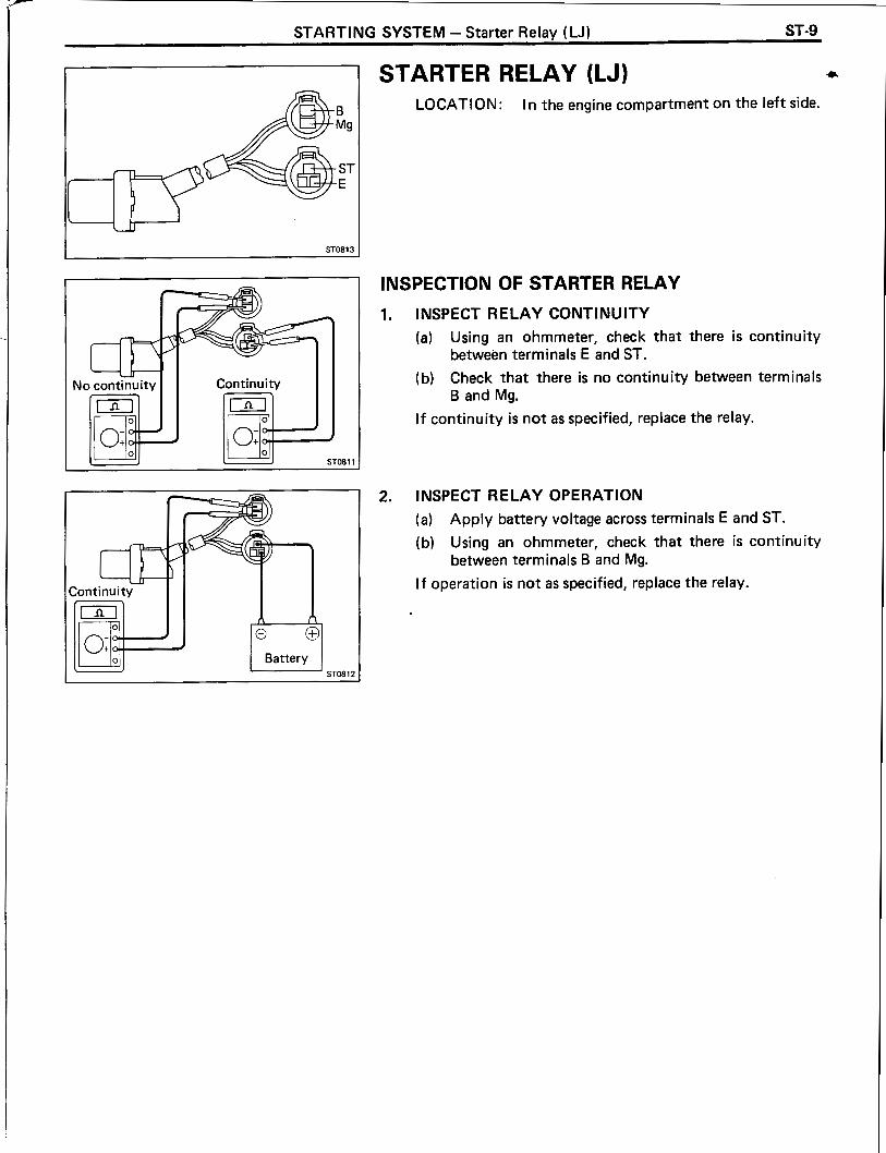
STARTING SYSTEM - Starter Relay ( W ) ST-9
INSPECTION OF STARTER RELAY
1. INSPECT RELAY CONTINUITY
(a) Using an ohmmeter, check that there is continuity between terminals E and ST.
(b) Check that there is no continuity between terminals B and Mg.
I f continuity is not as specified, replace the relay.
ST081 3
2. INSPECT RELAY OPERATION
(a) Apply battery voltage across terminals E and ST.
(b) Using an ohmmeter, check that there i s continuity between terminals B and Mg.
I f operation is not as specified, replace the relay.
STARTER RELAY (LJ) a
LOCATION: In the engine compartment on the left side.

CHARGING SYSTEM REFER TO 2L. 3L ENGINE REPAIR MANUAL (Pub. No. RM123E)
NOTE: The following pages contain only the points which differ from the above listed manual.
Page
CHARGING SYSTEM CIRCUIT ................................ CH-2
ON-VEHICLE INSPECTION ...................................... CH-3

CH-2 CHARGING SYSTEM - Charging System Circuit
CHARGING SYSTEM CIRCUIT -- -- -
LJ (w/ Hi-Speed Compact Type Alternator (w/ IC Regulator))
(w/ Tachometer) (W/O Tachometer)
Alternator
LN (w/ Conventional Type Alternator. (w/o IC Regulator))
I Starter Switch 1 I
" 1 Europe "2 Others
55A Type /
I I I I
Alternator Regulator Alternator 1, - -

INSPECT BATTERY SPEC1 FlC GRAVITY AND ELECTROLYTE LEVEL
CORRECT WRONG
(a) Check the specific gravity of each cell.
3.
Standard specific gravity: When fully charged at 20" C (68" F)
1.27 - 1 -29 (80D26R) 1.25 - 1.27 (Others)
I f not as specified, charge the battery.
(b) Check the electrolyte quantity of each cell.
I f insufficient, refill with distilled (or purified) water.
CHECK BATTERY TERMINALS, FUSIBLE LINKS AND FUSES
(a) Check that the battery terminals are not loose or cor- roded.
(b) Check the fusible links and fuses for continuity.
INSPECT DRIVE BELTS
(a) Visually check each belt for cracks, oiliness or wear. Check that the belt does not touch the bottom of the pulley groove. :
If one belt has any of the above defects, replace both belts.
(b) Check the drive belt deflection by pressing on the belt at the points indicated in the illustration with 10 kg (22.0 Ib, 98 N) of pressure.
Drive belt deflection: New belt 7 - 10 mm (0.28 - 0.39 in.) Used belt 10 - 15 mm (0.39 - 0.59 in.)
I f the deflection is not as specified, adjust it.
HINT: 0 "New belt" refers to a belt which has been used for 5
minutes or less on a running engine.
"Used belt" refers to a belt which has been used for 5 minutes or more on a running engine.
After installing a new belt, run the engine for about 5 minutes and recheck the deflection.

CH-4 CHARGING SYSTEM - On-Vehicle Inspection
(c) (Reference) Using SST, measure the drive belt tension.
SST 092 1 6-00020 and 092 16-00030
Drive belt tension: New belt 40 - 60 kg Used belt 20 - 35 kg
I f the belt tension is not as specified, adjust it.
VISUALLY CHECK ALTERNATOR WIRING AND LISTEN FOR ABNORMAL NOISES
(a) Check that the wiring is in good condition.
(b) Check that there is no abnormal noise from the alternator while the engine is running.
5. INSPECT DISCHARGE WARNING LIGHT CIRCUIT
(a) Warm up the engine and then turn it off.
(b) Turn off all accessories.
(c) Turn the starter switch to "ON". Check that the discharge warning light is lit.
(d) Start the engine. Check that the light goes out.
I f the light does not operate as specified, troubleshoot the discharge light circuit.
6. INSPECT CHARGING CIRCUIT WITHOUT LOAD
HINT: I f a batterylalternator tester is available, connect the tester to the charging circuit as per manufacturer's instructions.
(a) I f a tester is not available, connect a voltmeter and ammeter to the charging circuit as follows:
Disconnect the wire from terminal B of the alterna- tor and connect it to the negative (-) lead of the
I I Voltmeter I I ammeter.
Connect the positive (+) lead of the voltmeter to terminal B of the alternator.
Ground the negative (-) lead of the voltmeter.
+ * CH0837 Connect the positive (+) lead of the ammeter to
terminal B of the alternator.

CHARGING SYSTEM - On-Vehicle Inspection CH-5
W/ IC Regulator
CH0205 CHOOlO
W/O IC Regulator i i
W/ IC Regulator
inal F
(b) Check the charging circuit as follows: c With the engine running from idling to 2,000 rpm, check the reading on the ammeter and voltmeter.
(wlo IC Regulator)
Standard amperage: 10 A or less
Standard voltage: 13.8 - 14.4 V at 25" C (77" F)
I f the reading is not as standard voltage, adjust the regula- tor. I f necessary, replace regulator.
(wl IC Regulator)
Standard amperage: 10 A or less
Standard voltage: 13.9 - 15.1 V at 25°C (77" F) 13.5 - 14.3 V at 115°C (239" F)
I f the voltmeter reading is greater than standard voltage, replace the I C regulator.
I f the voltmeter reading is less than standard voltage, check the I C regulator and alternator as follows:
With terminal F grounded, start the engine and check the voltmeter reading of terminal B. I f the voltmeter reading is greater than standard voltage, replace the I C regulator.
I f the voltmeter reading is less than standard voltage, check the alternator.

CH-6 CHARGING SYSTEM - On-Vehicle Inspection
INSPECT CHARGl NG Cl RCUlT WITH LOAD
(a) With the engine running a t 2,000 rpm, turn on the high beam headlights and place the heater blower switch a t "HI ".
(b) Check the reading on the ammeter.
Standard amperage: 30 A or more
I f the ammeter reading is less than standard amperage, repair the alternator.
HINT: With the battery fully charged, the indication will sometimes be less than standard amperage.

SERVICE SPECIFICATIONS REFER TO 2L. 3L ENGINE REPAIR MANUAL (Pub. No. RM123E)
NOTE: The following pages contain only the points which differ form the above listed manual.
Page
ENGINE MECHANICAL ........................................... A-2
TURBOCHARGER SYSTEM ..................................... A-5
FUEL SYSTEM ...................................................... A-6
COOLING SYSTEM ................................................. A-1 3
LUBRICATION SYSTEM . . ... .. .. .. . ... .. ......... ... . .. . . ... .. . A-1 4
STARTING SYSTEM . . . . .. . . .... .. ... .. . .. . . . .. .. .. . . . . ... . . . . A-1 4
CHARGING SYSTEM . .. .. . . .. .. . . ... ... .. ....... ... .. . ... . . . . . A-1 4

A-2 SERVICE SPECIFICATIONS - Enaine Mechanical
ENGINE MECHANICAL
Specifications
Engine tune-up Coolant capacity (w/o Heater) LJ LN 2L-T
3L Coolant capacity (w/ Heater)
LJ LN 2L-T
3 L Coolant capacity (w l Front and rear heaters)
LJ LN 2L-T
3L Engine oil capacity (LJ 2L-T)
Drain and refill w l Oil filter change W/O Oil filter change
Dry fill Engine oil capacity (LJ 3L)
Drain and refill w l Oil filter change W/O Oil filter change
Dry fi l l Engine oil capacity (LN 2L-T)
Drain and refill w/ Oil filter change W/O Oil filter change
Dry fill Engine oil capacity (LN 3L)
Drain and refill w l Oil filter change W/O Oil filter change
Dry fill Engine oil API grade
2 L-T 3L -
Alternator drive belt Deflection New belt
Used belt Tension (Reference) New belt
Used be1 t Battery specific gravity
When fully charged at 2 0 ' ~ ( 6 8 ' ~ ) 80D26R Others
Injection nozzle opening pressure New nozzle
Reused nozzle
Valve clearance Intake Exhaust
10.0 liters 8.2 liters 8.1 liters
10.9 liters 9.1 liters 9.0 liters
11.5 liters 9.4 liters 9.3 liters
6.7 liters 5.7 liters 7.4 liters
6.7 liters 5.7 liters 7.4 liters
6.8 liters 5.8 liters 7.5 liters
5.8 liters 4.8 liters 6.5 liters
CD or better
10.6 US qts 8.7 US qts 8.6 US qts
11.5 US qts 9.6 US qts 9.5 US qts
12.2 US qts 9.9 US qts 9.8 US qts
7.1 US qts 6.0 US qts 7.8 US qts
7.1 US qts 6.0 US qts 7.8 US qts
7.2 US qts 6.1 US qts 7.9 US qts
6.1 US qts 5.1 US qts 6.9 US qts
8.8 Imp. qts 7.2 Imp. qts 7.1 Imp. qts
9.6 Imp. qts 8.8 Imp. qts 7.9 Imp. qts
10.1 Imp. qts 8.3 Imp. qts 8.2 Imp. qts
5.9 Imp. qts 5.0 Imp. qts 6.5 Imp. qts
5.9 Imp. qts 5.0 Imp. qts 6.5 Imp. qts
6.0 Imp. qts 5.1 Imp. qts 6.6 Imp. qts
5.1 Imp. qts 4.2 Imp. qts 5.7 Imp. qts
CC, CD or better
7 - 10mm 0.28 - 0.39 in. 10 - 15 mm 0.39 - 0.59 in. 40 - 60 kg 20 - 35 kg
151 - 159 kg/cm2 (2,148 - 2,261 psi, 14,808 - 15,593 kPa) 145 - 155 kg/cm2 (2,062 - 2,205 psi, 14,220 - 15,200 kPa) 0.20 - 0.30 mm 0.008 - 0.012 in. 0.40 - 0.50 mm 0.01 6 - 0.020 in.

SERVICE SPEC1 FlCATlONS - Engine Mechanical A-3
Specifications (Cont'd)
Engine tune-up (Cont'd)
Compression pressure
Cylinder head
Camshaft
New valve adjusting shim thickness
New valve adjusting shim thickness (cont'd)
Injection timing Plunger stroke
2L-T Austria
Others 3L
Idle speed 2 L-T 3 L
Maximum speed 2 L-T 3L Hong Kong, Singapore, Malaysi
Others A/C idle-up setting speed lnjection order
Engine revolution a t 250 rpm 2 L-T STD 3 L STD 2L-T, 3L Limit
Difference of pressure between each cylinder
New cylinder head gasket thickness Mark "B" Mark "DM Mark "F"
Cam lobe height 2 L-T STD Intake
Exhaust Limit Intake
Exhaust 3 L STD Intake
Exhaust Limit Intake
Exhaust
2.50 mm 2.55 mm 2.60 mm 2.65 mm 2.70 mm 2.75 mm 2.80 mm 2.85 mm 2.90 mrn 2.95 mm 3.00 mm 3.05 mm 3.10 mrn 3.15 mm 3.20 mm 3.25 mm 3.30 mm
0.0984 in. 0.1004 in. 0.1024 in. 0.1043 in. 0.1063 in. 0.1083 in. 0.1 102 in. 0.1 122 in. 0.1 142 in. 0.1 161 in. 0.1181 in. 0.1201 in. 0.1220 in. 0.1240 in. 0.1260 in. 0.1280 in. 0.1299 in.
Within the marks of belt case and pump flange. (See page EM-24) 0.54 - 0.66 mm 0.0213 - 0.0260 in. 0.84 - 0.96 rnm 0.0331 - 0.0378 in.
750 rpm 700 rpm
4,800 rpm 4,400 rpm 4,600 rprn 950 rpm 1 - 3 - 4 - 2 ( A - 8 - C - D )
31.0 kg/cm2 (441 psi, 3,040 kPa) or more 32.0 kg/cm2 (455 psi, 3,138 kPa) or more 20.0 kg/cm2 (284 psi, 1,961 kPa) 5.0 kg/cm2 (7 1 psi, 490 kPa) or less
1.40 - 1.50 mm 0.0551 - 0.0591 in. 1.50 - 1.60 mm 0.0591 - 0.0630 in. 1.60 - 1.70 rnm 0.0630 - 0.0669 in.
53.450 - 53.470 mrn 54.990 - 55.010 mm 52.95 mm 54.49 mm 54.290 - 54.310 mm 54.990 - 55.010 mm 53.79 mrn 54.49 mm
2.1043 - 2.1051 in. 2.1650 - 2.1657 in. 2.0846 in. 2.1453 in. 2.1374 - 2.1382 in. 2.1650 - 2.1657 in. 2.1177 in. 2.1453 in.

A-4 SERVICE SPECIFICATIONS - Engine Mechanical
Specifications (Cont'd)
Cylinder block
Piston and piston ring
Connecting rod
Crankshaft
Cylinder bore diameter 2 L-T STD Mark "1"
Mark "2" Mark "3"
Limit STD 01s 0.50
3 L STD Mark "1" Mark "2" Mark "3"
2 L-T Limit STD 01s 0.50
3L Limit STD 01s 0.50
Piston protrusion Piston diameter
2 L-T ST D
3 L STD
Piston oil clearance
Piston ring groove clearance 2 L-T STD
Limit
3L . STD
Limit
Mark "1" Mark "2" Mark "3" 01s 0.50 Mark "1" Mark "2" Mark "3" 01s 0.50 STD Limit
No. 1 No. 2 Oil
No. 1 No. 2 Oil
Rod bending Limit per 100 mm (3.94 in.) Twist Limit per 100 mm (3.94 in.) Connecting rod bolt outer diameter STD
Limit Bushing inside diameter STD Piston pin oil clearance ST D
Limit
Main journal diameter STD UIS 0.25 UIS 0.50
Crank pin diameter ST D UIS 0.25 UIS 0.50
Circle runout Limit Main journal taper and out-of-round Limit Crank pin taper and out-of-round Limit
92.000 - 92.010 mm 92.010 - 92.020 mm 92.020 - 92.030 mrn 92.23 rnm 92.73 mm 96.000 - 96.01 0 mm 96.01 0 - 96.020 mm 96.020 - 96.030 rnm 92.23 mm 92.73 mm 96.23 mm 96.73 mm
3.6220 - 3.6224 in. 3.6224 - 3.6228 in. 3.6228 - 3.6232 in. 3.631 1 in. 3.6508 in. 3.7795 - 3.7799 in. 3.7799 - 3.7803 in. 3.7803 - 3.7807 in. 3.631 1 in. 3.6508 in. 3.7886 in. 3.8083 in.
0.0268 - 0.0382 in.
0.028 - 0.077 mm 0.070 - 0.1 15 mrn 0.030 - 0.070 mm 0.20 mm 0.028 - 0.077 mm 0.060 - 0.105 mm 0.030 - 0.070 mm 0.20 mm
0.05 mm 0.15 mm 8.400 - 8.600 mm 8.20 mm 29.008 - 29.020 mm 0.004 - 0.012 mm 0.05 mm
61.985 - 62.000 rnm 61.745 - 61.755 mrn 61.495 - 61.505 mm 54.988 - 54.000 mm 54.745 - 54.755 mm 54.495 - 54.505 mm 0.06 mm 0.02 mm 0.02 mm
3.6197 - 3.6201 in. 3.6201 - 3.6205 in. 3.6205 - 3.6209 in. 3.6394 - 3.6405 in. 3.7772 - 3.7776 in. 3.7776 - 3.7779 in. 3.7779 - 3.7783 in. 3.7968 - 3.7980 in. 0.0020 - 0.0028 in. 0.0055 in.
0.001 1 - 0.0030 in. 0.0028 - 0.0045 in. 0.0012 - 0.0028 in. 0.008 in. 0.001 1 - 0.0030 in. 0.0024 - 0.0041 in. 0.0012 - 0.0028 in.
0.0020 in. 0.0059 in. 0.3307 - 0.3386 in. 0.3228 in. 1.1420 - 1.1425 in. 0.0002 - 0.0005 in. 0.0020 in.
2.4403 - 2.4409 in. 2.4309 - 2.4413 in. 2.421 1 - 2.4215 in. 2.1649 - 2.1654 in. 2.1553 - 2.1557 in. 2.1455 - 2.1459 in. 0.0024 in. 0.0008 in. 0.0008 in.

.-
SERVICE SPECIFICATIONS - Engine Mechanical. Turbocharger Svstem A-5
Torque Specifications
Part tightened
Camshaft bearing cap x Cylinder head
Camshaft oil seal retainer x Cylinder head
Cylinder head x Cylinder block 1st
2nd
3rd
Cylinder head cover x Cylinder head
RH engine hanger x Cylinder head
Exhaust manifold x Cylinder head
Heat insulator x Exhaust manifold
lntake manifold x Cylinder head
EGR pipe x lntake manifold (Austria)
EGR valve adaptor x EGR valve (Austria)
LH engine hanger x Cylinder head
Water outlet housing x Cylinder head
No. 2 timing belt cover x Cylinder head
Connecting rod cap x Connecting rod 1st
2nd
TURBOCHARGER SYSTEM
Specifications
kg-cm ft-lb N-m
255
185
800
90' turns
90' turns
50
380
530
120
240
130
195
380
195
185
350
120' turns
Turbocharger
Turbine outlet elbow x Turbocharger
Turbo water pipe x Turbocharger
Turbocharger x Exhaust manifold
Turbo oil pipe x Turbocharger
Turbo oil pipe x Cylinder block
Exhaust manifold stay x Cylinder block
Exhaust manifold stay x Turbocharger
Turbocharger heat insulator x Turbocharger
lntake pipe x lntake manifold
Torque Specifications
Turbocharging pressure
Impeller wheel axial play
Impeller wheel radial play
Part tightened
0.61 - 0.81 kg/cm2
(8.7 - 11.5 psi, 60 - 79 kPa)
0.13 mm (0.0051 in.) or less
0.1 8 mm (0.0071 in.) or less
kg-cm ft-lb N .m

A-6 SERVICE SPECIFICATIONS - Fuel Svstem
FUEL SYSTEM
Specifications
Fuel heater
Injection pump
Resistance a t 2 0 " ~ ( 6 8 " ~ )
Part No. 2L-T Austria
Others 3L Hong Kong, Singapore, Malaysia
Others w/o HAC wlo Tacho. W/O HAC w l Tacho. w l HAC w/o Tacho. w l H AC w/ Tacho.
Direction of rotation lnjection order PIJ opening pressure (2L-T Austria only)
PIJ adjusting shim thickness (2L-T Austria only)
Approx. 0.7 Ct
22 100 - 58280 22 100 - 5B270 22 100 - 5B030 22 100 - 54850 22 100 - 54860 22 100 - 54870 22 100 - 54880 Clockwise as seen from drive side 1 - 3 - 4 - 2 ( A - B - C - D ) 123 - 127 kg/cm2 (1,749 - 1,806 psi, 12,054 - 12,446 kPa) 0.500 mm 0.0197 in. 0.550 mm 0.0217 in. 0.600 mm 0.0236 in. 0.650 mm 0.0256 in. 0.700 mm 0.0276 in. 0.750 mm 0.0295 in. 0.800 mm 0.0315 in. 0.850 mm 0.0335 in. 0.900 mm 0.0354 in. 0.950 mm 0.0374 in. 1.000 mm 0.0394 in. 1.025 mm 0.0404 in. 1 .050 mm 0.0413 in. 1 .075 mm 0.0423 in. 1 .I00 mm 0.0433 in. 1.125 mm 0.0443 in. 1.150 mm 0.0453 in. 1.175 mm 0.0463 in. 1.200 mm 0.0472 in. 1.225 mm 0.0482 in. 1.250 mm 0.0492 in. 1.275 mm 0.0502 in. 1.300 mm 0.0512 in. 1.325 mm 0.0522 in. 1.350 mm 0.0531 in. 1.375 mm 0.0541 in. 1.400 mm 0.0551 in. 1.425 mm 0.0561 in.
0.0571 in. 0.0581 in. 0.0591 in. 0.0600 in. 0.061 0 in. 0.0620 in. 0.0630 in. 0.0640 in. 0.0650 in. 0.0659 in. 0.0669 in.
1.725 mm 0.0679 in. 1.750 mm 0.0689 in.

r
SERVICE SPECIFICATIONS - Fuel Svstem
Specifications (Cont'd)
Injection pump (cont'd)
PIJ adjusting shim thickness (2L-T Austria only) (con t'd)
Spring free length Delivery valve spring Plunger spring Coupling spring Pneumatic bellows spring (w/ HAC only) Boost compensator spring (2L-T only)
Austria Sub Main
Others PIJ piston lift gap (2L-T Austria drily) Plunger stroke (2L-T Austria only) Boost compensator adjusting shim A thickness (2L-T only)
Boost compensator adjusting shim B thickness (2L-T Austria only)
Boost compensator sub spring constant (2L-T Austria only)
1.775 mrn 0.0699 in. .800 rnrn .825 mrn .850 rnrn .875 rnrn .900 mrn .925 rnrn .950 rnrn
1.975 rnrn 2.000 rnrn 2.050 rnrn 2.100 rnrn 2.150 rnrn 2.200 rnrn 2.250 rnrn 2.300 mrn 2.350 rnrn 2.400 rnrn 2.450 mrn 2.500 mm
24.4 rnrn 30.0 mrn 16.0 mrn 35.0 rnrn
22.3 rnrn 24.1 rnm 19.4 rnrn 0.175 - 0.475 rnrn 0.60 - 0.80 rnrn 1.1 rnrn 1.3 rnrn 1.5 rnrn 1.7 mrn 1.9 rnrn 2.1 rnrn 2.3 mrn 2.5 rnrn 2.7 rnrn 2.9 rnrn 3.1 mrn 3.3 rnrn 12.90 rnrn 13.15 mrn 13-40 rnrn 1.2 kg/crn2 1.4 kg/crn2
0.0709 in. 0.0719 in. 0.0728 in. 0.0738 in. 0.0748 in. 0.0758 in. 0.0768 in. 0.0778 in. 0.0787 in. 0.0807 in. 0.0827 in. 0.0846 in. 0.0866 in. 0.0886 in. 0.0906 in. 0.0925 in. 0.0945 in. 0.0965 in. 0.0984 in.
0.961 in. 1.181 in. 0.630 in. 1.378 in.
0.878 in. 0.949 in. 0.764 in.
0.00689 - 0.01870 in. 0.0236 - 0.0315 in.
0.039 in. 0.051 in. 0.059 in. 0.067 in. 0.075 in. 0.083 in. 0.090 in. 0.098 in. 0.106 in. 0.1 14 in. 0.122 in. 0.130 in. 0.508 in. 0.518 in. 0.528 in. 1.04 Iblin. 1.22 Iblin.

A-8 SERVICE SPECIFICATIONS - Fuel Svstem
Injection Pump Adjustment
Preparation of pump tester
Full load injection volume pre-setting
Maximum speed pre-setting
Pump inner pressure
Overflow volume
Test nozzle type Test nozzle opening pressure
Injection pipe Outer diameter lnner diameter Length Minimum bending radius
Fuel temperature Fuel feeding pressure Fuel cut solenoid voltage
ltem Adjusting
lever position
Maximum Austria speed side
2L-T Maximum
Others speed side
Hong Kong, Singapore, Maximum speed side
Others speed side
ltem Adjusting
lever position
Maximum speed side
2L-T Maximum speed side
Others
3 L Maximum speed side
DN12SD12 145 - 155 kg/cm2 (2,062 - 2,205 psi, 14,220 - 15,200 kPa)
Hong Kong, Singapore, Malaysia
6.0 mm 0.236 in. 2.0 mm 0.079 in. 840 mm 33.07 in. 25 mm (0.98 in.) or more 40 - 4 5 ' ~ 0.2 kg/cm2 (2.8 psi, 20 kPa) 6 V
Maximum speed side
strokes
/ NO. of I Injection
-
cc (cu in.)
Pump rpm I measuring I volume
Pump rpm
Pump rpm I Inner pressure kg/cm2 (psi, kPa)
-
-
-
-
-
-
-
-
-
-
-
-
-
-
No. of measuring
strokes
l njection volume
cc (cu in.)
2,100
Pump rpm
6.6 - 7.2 (94 - 102,647 - 706)
Overflow volume cc/min. (cu in./min.)
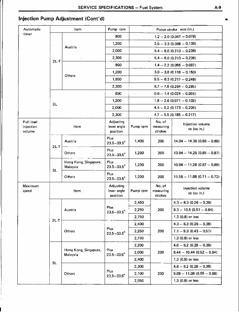
SERVICE SPECIFICATIONS - Fuel System A-9
lnjection Pump Adjustment (Cont'd)
Automatic timer
Item Pump rpm Piston stroke mm (in.)
800 1.2 - 2.0 (0.047 - 0.079)
Austria
2 L-T
Others
Full load injection volume
Adjusting No. of lnjection volume
lever angle Pump rpm measuring cc (cu in.)
position strokes ltem
Austria
2 L-T
Others
Hong Kong, Singapore, Plus Malaysia 23.5-33.5" 1 1,200 1 200 1 10.96 - 1 1.28 (0.67 - 0.69) Others
Maximum speed ltem
Adjusting lever angle position
Austria
Pump rpm
Plus 23.5-33.5'
Plus 23.5-33.5'
2 L-T
Others
No. of measuring
strokes
2,450
2,250 -
2,750
2,400
2,250 .
2,750
Hong Kong, Singapore, Plus 8.44 - 10.44 (0.52 - 0.64)
Malaysia 23.5-33.5"
lnjection volume cc (CU in.)
I 1 1.3 (0.8) or less
200
200
Others
~
4.3 - 6.3 (0.26 - 0.38)
8.3 - 10.5 (0.51 - 0.64)
1.3 (0.8) or less
4.3 - 6.3 (0.26 - 0.38) 7.1 - 9.3 (0.43 - 0.57) 1.3 (0.8) or less
2,550 1.3 (0.8) or less

A-10 SERVICE SPECIFICATIONS - Fuel System
Injection Pump Adjustment (Cont'd) -
'ump rpm
1,400
No. of measuring
strokes
Injection vol ume
cc (cu in.)
Variation limit
cc (cu in.)
Injection volume
Adjusting lever angle position
Austria
2 L-T
-
3 L
-
Plus 23.5-33.5O Others
Hong Kong, Singapore, Malaysia
Plus 23.5-33.5'
Others Plus 23.5-33.5O
10.19 - 11.09
0.1 18 in. 0.122 in. 0.126 in. 0.130 in.
Governor sleeve plug head thickness
0.1 34 in. 0.138 in. 0.142 in. 0.146 in. 0.150 in. 0.154 in. 0.158 in. 0.161 in. 0.165 in.

SERVICE SPECIFICATIONS - Fuel System A-1 1
lnjection Pump Adjustment (Cont'd)
Full-load minimum injection volume
Boost compensator characteristic
Boost compensator characteristic tendency
Load sensing timer (W/O HAC)
I No. of measuring Injection volume Pump rpm
strokes cc (cu in.)
2 L-T
l tem
Austria
Others
2 L-T
2 L-T
Pump rpm
l tern
Austria
Others
1,400
500
Austria
Others
Boost pressure kg/cm2 (psi, kPa)
Pump
rpm
200
200
500
1,200
1.400
1,400
500
500
1,200
1,200
1,200
1,200
Remark
8.8 - 10.0 (0.54 - 0.61 )
10.6 - 11.4 (0.65 - 0.70)
No. of measuring
stroke
Boost pressure kg/cm2 (psi, kPa)
Pump No. of measuring Item I rpm / stroke.
Injection volume cc (cu in.)
0 (0, 0)
0.41 (5.9,40)
0.74 (10.5, 73)
0.68 (9.6, 66)
0.41 (5.9, 40)
0 (0, 0)
0.74 (10.5,73)
0.63 (9.0, 62)
0.41 (5.9,40)
0.14 (2.0, 14)
Injection volume cc (cu in.)
No. of measuring
strokes
2 L-T
3L
Remark
200
200
200
200
Pump No. of measuring I rpm I strokes
2 L-T / 1,200 1 200 1 8.10-8.50 (0.49-0.52) 1
10.8 - 1 1.6 (0.65 - 0.71 )
12.9 - 13.5 (0.79 - 0.82)
Injection volume cc (cu in.)
1,200
1,200
Injection volume cc (cu. in.)
Hysterises cc (CU in.)
13.84 - 14.36 (0.84 - 0.88)
13.94 - 14.26 (0.85 - 0.87)
14.60 - 15.40 (0.89 - 0.94)
10.80 - 1 1.60 (0.66 - 0.7 1 )
13.84 - 14.36 (0.84 - 0.88)
13.94 - 14.26 (0.85 - 0.87)
12.90 - 13.50 (0.79 - 0.82)
11.20 - 12.00 (0.68 - 0.73)
- -
0.3 (0.02) or less
- - -
0.3 (0.02) or less
-
200
200
3~
Others
Measured value at step a t (b) minus 0.6 (0.04) + 0.4 (0.02)
Measured value a t step at (b) minus 1 .O (0.06) * 0.4 (0.02)
Hong Kong, Singa- pore, Malaysia
I 1,200 1 200 1 8.12-8.52 (0.50-0.52)
2 L-T
3 L
Set to starting point
Check ending point
1,200
1,200
1,200
Timer piston fluctuation mm (in.)
200
l tern
1.44 - 1.84 (0.057 - 0.072)
0.62 - 1.02 (0.024 - 0.040)
8.72-9.12 (0.52-0.56)
Pump rpm

A-12 SERV CE SPECIFICATIONS - Fuel Svstem
Injection Pump Adjustment (Cont'd)
Idle speed Adjusting lever angle position
Pump rpm
Remarks No. of
measuring strokes
lnjection volume cc (cu in.)
l tem Variation
limit cc (cu in.)
-
2 L-T
q = 2.4 - 2.6 (0.15 - 0.16)
q plus 0.5 (0.03) or more + Minus
13.5 - 21.5' Austria ~ -
q minus 1.1-2.1 (0.07 - 0.13) I -
Adjust
q plus 0.5 (0.03) or more I - Minus
13.5 - 2 1.5' Others
Adjust
q minus 0.7-1.7 (0.04 - 0.10)
1.8 - 2.8 (0.11 -0.17)
1.8 - 2.8 (0.11 -0.17)
Adjust
-
0.34 (0.02)
0.34 (0.02) Minus
12.5 - 22.5' -
Remarks Dash pot
l tem Pump rpm
Austria
No. of measuring strokes -
2 L-T
lnjection volume cc (CU in.)
Lever set
q plus 0.2 - 0.4 (0.01 - 0.02) Adjust
Lever set
Others q plus 0.2 - 0.4
(0.01 - 0.02) Adjust
Cold start system
l tem Fuel temp. O C ( O F )
25 (77) Austria 2 L-T
Others
Timer piston stroke mm (in.)
0.7 - 0.9 (0.028 - 0.035)
Fast idle Fuel temp. O C ( O F ) I Clearance mm (in.) l tem
2 L-T
Adjusting lever
Item
2 L-T
Lever moving angle
41 - 51'

SERVICE SPEC1 FlCATlONS - Fuel System, Cooling System A-1 3
Torque Specifications
Part tightened
Retaining nut x Holder body (2L-T Austria)
Distributive head plug x Distributive head
Pilot injection actuator x Distributive head (2L-T Austria)
Governor cover x lnjection pump body
Fuel cut solenoid x Distributive head
Pickup sensor x lnjection pump body
Fuel inlet pipe x lnjection pump
Fuel outlet pipe x lnjection pump
lnjection pump x Timing belt case
Pump stay x lnjection pump
Pump stay x Cylinder block
lnjection pipe x lnjection nozzle
lnjection pipe x lnjection pump
lnjection pump drive pulley x lnjection pump
Crankshaft timing pulley x Crankshaft
COOLING SYSTEM
Specifications
kg-cm ft-lb N m
Torque Specifications
See page A-2
0.75 - 1.05 kg/cm2 (10.7 - 14.9 psi, 74 - 103 kPa)
0.6 kg/cm2 (8.5 psi, 59 kPa)
86 - 90°c 187 - 1 9 4 " ~
8 mm (0.31 in.) or more
Engine coolant capacity
Radiator cap
Thermostat
Part tightened
Cylinder block x Drain plug
Water outlet x Water outlet housing
Relief valve opening pressure STD
. Limit
Valve opening temperature
Valve l i f t at 1 0 0 " ~ (212"~ )
kg-cm ft-lb N.m
300 22 29
195 14 19

A-14 SERVICE SPECIFICATIONS - Lubrication Svstem, Starting System, Charging System
LUBRICATION SYSTEM
Specifications
Torque specifications
Part tightened
See page A-2
0.3 kg/cm2 (4.3 psi, 29 kPa) or more 3.0 - 5.5 kg/cm2 (43 - 78 psi, 294 - 539 kPa)
Engine oil capacity
Engine oil drain plug Oil cooler x Oil filter bracket Oil cooler bracket x Cylinder block Bolt Oil cooler bracket x Cylinder block Nut Relief valve plug x Oil filter bracket Union x Oil filter bracket (2L-T) Union bolt x Oil filter bracket (LJ 2L-T) Alternator x Engine RH mounting bracket 14 mm head bolt Alternator x Fan belt adjusting bar 12 mm head bolt
Oil pressure
STARTING SYSTEM
at idling at 3000 rpm
Pre-heating system
-
kgcm ft-lb N m
400 29 39 145 10 14 195 14 19 210 15 2 1 370 27 36 500 36 49 200 14 20 510 37 50 130 9 12
Light lighting time Supper glow type Fixed delay type
Water temp. sensor resistance at - 2 0 " ~ (-4°F) at 0°C (32°F) at 20°C (68°F) at 40°C (104°F) at 60°C (140°F) at 80°C (176°F)
See page ST-3 Approx. 6 seconds
CHARGING SYSTEM
See page A-2
1.27 - 1.29 1.25 - 1.27
13.8 - 14.4 V 13.9 - 15.1 V 13.5 - 14.3 V
Drive belt deflection and tension
Battery specific gravity when fully charged at 20°C (68°F) 80D26R Others
Alternator regulator
Regulating voltage WIO IC regulator at 2 5 " ~ (77°F) w l IC regulator at 25°C (77°F)
at 115°C (239°F)
STANDARD BOLT TORQUE SPECIFICATIONS
Page
STANDARD BOLT TORQUE SPECIFICATIONS ........... 6-2

6-2 STANDARD BOLT TORQUE SPECIFICATIONS
STANDARD BOLT TORQUE SPECIFICATIONS HOW TO DETERMINE BOLT STRENGTH
Hexagon head bolt
Hexagon flange bolt
W/ washer hexagon bolt
Hexagon head bolt
Hexagon flange bolt
W/ washer hexagon bolt
Hexagon head bolt
Hexagon head bolt
Mark I class
Bolt 6-
Stud bolt
0 iz:ruding lines Welded bolt 6T
Mark Class

STANDARD BOLT TORQUE SPECIFICATIONS B-3
SPECIFIED TORQUE FOR STANDARD BOLTS
Diameter mm
Pitch mm Hexagon head bolt
kg-an ft-ib N .m
55 48 in.-lb 5 130 9 12.5
260 19 2 6
480 35 47
760 5 5 74
1,150 8 3 11 5
Hexaaon flange bolt
kg-an ft-lb N*m

SST AND SSM REFER TO 2L, 3L ENGINE REPAIR MANUAL (Pub. No. RM123E)
NOTE: The following pages contain only the points which differ from the above listed manual.
Page
............................... SST (SPECIAL SERVICE TOOLS) C-2
....................... SSM (SPECIAL SERVICE MATERIALS) C-2

C-2 SST AND SSM - SST (S~ecial Service Tools)
SST (SPECIAL SERVICE TOOLS) Section
\
Note I Part No.
NI Sender gauge Angled Open End Wrench 12 x 14 mm
Belt Tension Gauge
Belt Tension Gauge Cable
N / By-pass element type
Oil Filter Wrench
FUII flow type
Oil Filter Wrench
Water Pump Overhaul Tool Set
- - - - - - - - - - - - - -
(Shaft "C")
- - - - - - - - - - - - - Sovernor sleeve plug
lnjection Pump Stand Set
Injection Pump Stand Arm
Valve Clearance Adjusting Tool
Injection Pump Tool Set
' Distributor Head Plug (Wrench
(Socket 14 mm)
Plunger Stroke Measuring Tool

SST AND SSM - SST (Special Service Tools), SSM (Special Service Materials) C-3
SST (SPECIAL SERVICE TOOLS) (Cont'd) Section
Part Name Note
Part No.
Illustration Jnion
Output Shaft Bearing Lock Nut Wrench
Cylinder Compression Check Gauge Set
(No. 4 Attachment)
(Gauge Assy)
Turbocharger Pressure Gauge
SSM (SPECIAL SERVICE MATERIALS) Use etc.
Seal packing or equivalent
Sac. Part Name
Cylinder head cover
Half circulator plug
Part No.
Adhesive 1324,
Three bond 1324 or equivalent
Union
Union bolt
Adhesive 1344,
Three bond 1344,
Loctite 242 or equivalent
Oil pressure switch or sender gauge