Forensic Engineering Report -...
28
Forensic Engineering Report Failure Analysis of the 2014 Launch Campaign Authors: Jeroen Wink Ralph Huijsman Tobias Knop Martin Olde Geert Henk Visser Johannes Ehlen Version: V 1.0 Thursday 8 th January, 2015
Transcript of Forensic Engineering Report -...

Forensic Engineering ReportFailure Analysis of the 2014 Launch Campaign
Authors:Jeroen WinkRalph HuijsmanTobias KnopMartin OldeGeert Henk VisserJohannes Ehlen
Version:V 1.0 Thursday 8th January, 2015

1. Introduction
This documents reports on the forensic engineering performed after the failed launch attemptof the Stratos II sounding rocket. Stratos II is a rocket developed by Delft Aerospace RocketEngineering (DARE). The rocket is powered by a single stage hybrid motor and has a designapogee of 50 [km]. An overview of the rocket’s design is given in section 2
The rocket was supposed to launch in the first week of October 2014 from the CEDEA launchbase in Spain. In total two launch attempts were performed. Both attempts were unsuccess-ful. Two main problems occurred: a failure in the reliability of the Flight Termination System(FTS) and a leak in the oxidiser feed system. Due to these reasons, the first attempt wasaborted and the second attempt failed.
After the launch campaign, the rocket was shipped back to Delft, where the forensic analy-sis was performed. The analysis and conclusions are documented in this report. Section 3gives an detailed overview of the factual information of launch attempt 1. Section 4 presentsthe same information for attempt 2. Encountered problems that were not specifically linked toone of the attempts are presented in Section 5. Concluding remarks are given in section 6 andfinally recommendations concerning changes in design and operations are listed in section 7.
1

2. Rocket Information
This section provides a concise overview of the Stratos II sounding rocket in the state as it wasduring the launch attempt in October 2014. Additionally, a brief description of the launch siteand corresponding airspace is given. At the end of the section a list of tests performed on therocket subsystems that where performed prior to the launch attempts is presented.
General Rocket Description
Stratos II is a sounding rocket designed to fly up to 50 km altitude carrying a scientific payloadand is to be recovered after launch. The rocket consists of a single stage hybrid propulsionsystem, a capsule housing the electronics and payloads and parachute bay carrying a two stageparachute. The rocket is approximately 7 m long, has an diameter of 200 mm for the motorsection and a diameter of 160 mm for the capsule section. The rocket was launched from theCEDEA Launch site at El Arenosillo, Spain.
Figure 1: The complete Rocket on the Launchtower in a Horizontal Position
Motor Description
The motor, named DHX 200 Aurora, has an initial thrust of 10 kN and a design impulseof 200,000 Ns. The actual impulse is expected to be lower and in the order of 180,000 Ns.The motor uses nitrous oxide as oxidizer and is fed by the self pressurising effect of the nitrousoxide. The fuel of the motor is a in house developed mixture of sorbitol, paraffin and aluminium.
On the launch pad, the oxidiser tank is filled from commercial gas cylinders containing thenitrous oxide provided by Praxair. The filling of the oxidizer tank is conducted remotely. After
2

filling the tank is pressurised using the ambient heat. Upon motor start, the motor is ignitedusing a small nitrous oxide bypass line , operated by the ignition valve, and a small pyrotechnicigniter. After the motor is primed, the main valve is opened and the motor fully ignites. Anoverview of the rocket feed system is given in figure 2
NitrousOxide
Cylinder1
NitrousOxide
Cylinder2
NitrousOxide
Cylinder3
CV-1 - CV-5
CV-7
CGR-2
MV-1
IV-1
PRV BV
APSDPS-1
DPS-2
SmallNitrogenCylinder
Motor
Run tank
FV-1
CGRV-2
N ON
2
2
DV-1
NitrousOxide
Cylinder4
NitrousOxide
Cylinder5
DV-2
Figure 2: Feedsystem Diagram of the Rocket and Filling system
Capsule Description
The nose cone of the rocket as a von Karman Ogive shape and is constructed from glass fi-bre composite as radio transparency is one of the requirements from the the electronics insideStratos II. Since at the concerned speeds the temperatures can rise to approximately 1000 K,the tip was made out of steel and aluminium.
The flight computer and power and payload systems are placed on two CNC machined bulkheadswith a cubesat like structure between them. This layout allows for assembly of all electronicswith relative ease as placing the nosecone is one of the last steps during assembly.
The recovery system consists of a two stage, spring-loaded parachute system designed to recoverthe entire rocket. A disk-gap band drogue chute will be deployed at transsonic speeds shortlyafter reaching apogee. This reduces its speed to below Mach one on its way back to earth. Thebigger cross shaped main parachute will be deployed shortly before touchdown for a soft waterlanding.
For the deployment of the parachutes a mechanical separation device was designed to sepa-rate the capsule from the motor. This clamp band system is a compact way to cleanly separatetwo or three rocket sections. It is typically used for the connections between launcher vehicles
3
and satellites. The design was repeatedly tested via load tests and has been flight-proven onDAREs regular launch campaigns to 1-2 km.
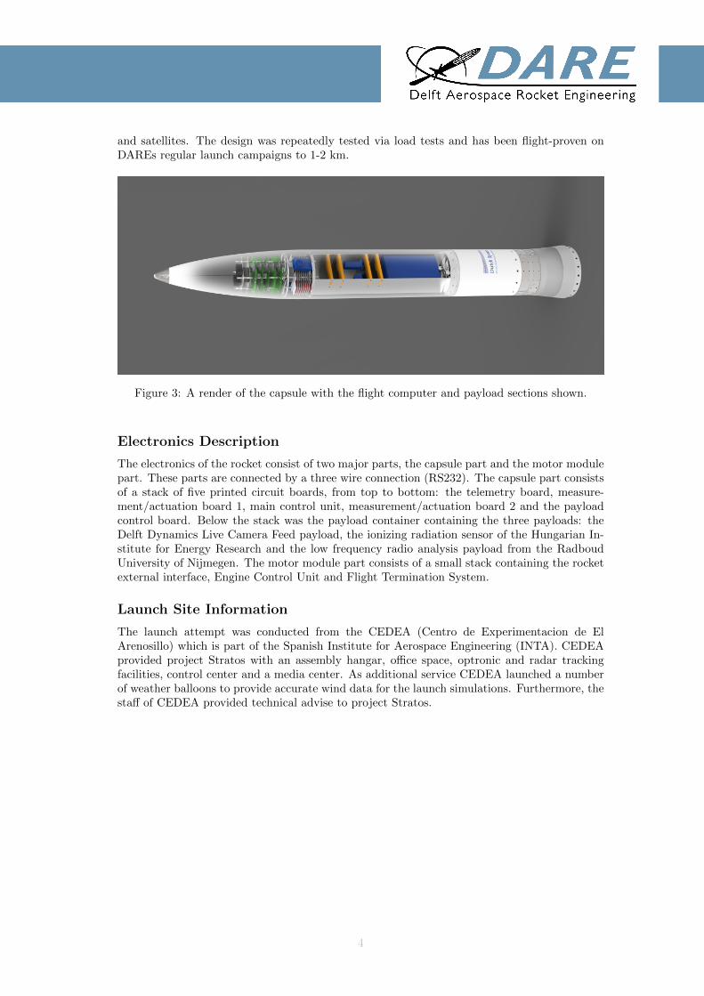
Figure 3: A render of the capsule with the flight computer and payload sections shown.
Electronics Description
The electronics of the rocket consist of two major parts, the capsule part and the motor modulepart. These parts are connected by a three wire connection (RS232). The capsule part consistsof a stack of five printed circuit boards, from top to bottom: the telemetry board, measure-ment/actuation board 1, main control unit, measurement/actuation board 2 and the payloadcontrol board. Below the stack was the payload container containing the three payloads: theDelft Dynamics Live Camera Feed payload, the ionizing radiation sensor of the Hungarian In-stitute for Energy Research and the low frequency radio analysis payload from the RadboudUniversity of Nijmegen. The motor module part consists of a small stack containing the rocketexternal interface, Engine Control Unit and Flight Termination System.
Launch Site Information
The launch attempt was conducted from the CEDEA (Centro de Experimentacion de ElArenosillo) which is part of the Spanish Institute for Aerospace Engineering (INTA). CEDEAprovided project Stratos with an assembly hangar, office space, optronic and radar trackingfacilities, control center and a media center. As additional service CEDEA launched a numberof weather balloons to provide accurate wind data for the launch simulations. Furthermore, thestaff of CEDEA provided technical advise to project Stratos.
4

Figure 4: Base map with locations of the relevant buildings and stations.
To ensure the safety during launch, CEDEA closed off parts of the air and sea space aroundthe base. Figure 5 shows the closed off zone. The white lines indicate the airspace under controlof CEDEA. The yellow/black cone shows the sector of air and sea space that was closed offduring the launch attempts.
5
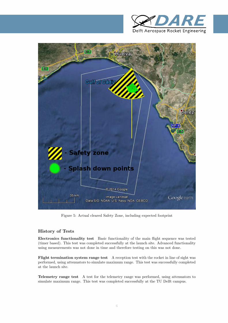
Figure 5: Actual cleared Safety Zone, including expected footprint
History of Tests
Electronics functionality test Basic functionality of the main flight sequence was tested(timer based). This test was completed successfully at the launch site. Advanced functionalityusing measurements was not done in time and therefore testing on this was not done.
Flight termination system range test A reception test with the rocket in line of sight wasperformed, using attenuators to simulate maximum range. This test was successfully completedat the launch site.
Telemetry range test A test for the telemetry range was performed, using attenuators tosimulate maximum range. This test was completed successfully at the TU Delft campus.
6

Live video feed test A test for the live video feed range and quality was performed, usingattenuators to simulate maximum range and a monitor to judge the image quality. This testwas completed successfully once at the launch site and once at the TU Delft campus.
RF compatibility test An RF (Radio Frequency) compatibility test was done with thesystems on the base. This test was completed successfully. One important test case wasomitted due to lack of time and underestimation of the risk. This was the test with the flighttermination system and the rocket telemetry system. Later on these systems turned out tointerfere. Concluding, it can be said that this test was not done properly.
Thermal cutter test An actuation test with the thermal cutters was performed to verifythe separation mechanism for the recovery system. The result of this test was dissatisfactorybecause of the long and unpredictable actuation time. The problem was mitigated by changingthe resistance values of the thermal cutters from 15Ω to 5Ω. Several test where performed toevaluate the performance of the new configuration and it was confirmed that the cutting timewas brought down from 8 seconds ± 2 down to 3 seconds ± 2 which was deemed acceptable.
Ground support equipment test A test was performed evaluating the performance of theground support equipment. The full sequence of events up to launch was tested successfully atthe launch site as well as in Delft (multiple times). This test includes all of the valve actuations,filling line cutting, load cell response and pressure sensor response.
Pressurized components Both bulkheads, including all their actual flight components, havebeen wet-tested in Delft on a shortened tank with nitrous oxide. A complete cycle of filling,holding, bleeding and ignition sequence have been successfully performed. No anomalies werefound with any component. Specifically the check valve and the teflon crush rings that exhibitedfailures later in the mission worked nominally.
Ingiter test A test was performed with the actuation of the pyrotechnic igniter. This testwas completed successfully once at the TU Delft campus and once at the launch site.
Vibration test A vibration test was done on the flight termination system, at the launchsite. The system failed under application of wide band vibrational pulses. This was fixed bychanging the demodulation circuit.
Individual electronic/software component tests A large amount of tests of individualboard and software components where done. The full description of all these tests is out of thescope of this report, and therefore not included. In the case that these tests where unsuccessful,the problem was immediately fixed, so that before the launch all the tested components worked.
7

3. Failure Analysis Launch Attempt 1
Factual Information
Key Personnel Attempt 1
The crew of the test and their function are listed below.
Name Role location Organi--zation
Time atorgan-isation(years)
Jose Ramon Garcia Santos Aerial Safety Offi-cer
Mission Control INTA n.a.
Robert Werner RSO Liaison Mission Control DARE 4Rob Hermsen Flight Director Mission Control DARE 5G.H. Visser Communication Mission Control DARE 6Ralph Huijsman Communication Mission Control DARE 4Antonio Luna de Gracia Ground Safety Of-
ficerHangar INTA n.a.
Jose Maria Castro Ceron Ground SystemsTechnician
Hangar INTA n.a.
Tobias Knop Ground Safety Of-ficer
Hangar DARE 4
Stefan Powell Test Engineer Hangar DARE 4Jeroen van Straten Rocket Interface Hangar DARE 5Douwe van Willigen Rocket interface Hangar DARE 3Maurits van Heijningen Telemetry Offsite Post DARE 5Nils von Storch Telemetry Offsite Post DARE 4Radu Florea Telemetry Weather Station DARE 1Johannes Ehlen FTS Operator Optronics Control DARE 3
8

Timeline of events
Table 1
ID Start ofevent
Event du-ration
Event description
LA1-01
0:00:00 N.A. livestream online.
LA1-02
0:02:50 Launchbox test a hangar.
LA1-03
0:15:00 N.A. Rocket transported to launchpad.
LA1-04
0:18:00 N.A. Rocket transferred from cart to tower.
LA1-05
1:23:00 15:00 Launch tower raised.
LA1-06
4:00:00 N.A. Telemetry test.
LA1-07
4:12:00 N.A. Decision made to reset Go-Pro.
LA1-08
4:34:00 15:00 Go-Pro reset.
LA1-09
5:45:00 N.A. Balloon launched.
LA1-10
4:12:00 N.A. Decision made to reset Go-Pro.
LA1-11
4:34:00 53:00 Go-Pro reset.
LA1-12
5:45:00 N.A. 1st Balloon launched.
LA1-13
7:21:00 34:00 Start of pad Operations.
LA1-14
7:55:00 N.A. End pad opperations.
LA1-15
8:10:00 N.A. 2nd Balloon launched.
LA1-16
8:30:00 N.A. Filling started.
LA1-17
9:00:00 N.A. Filling completed.
LA1-18
9:32:00 N.A. Umbilical cut.
LA1-19
9:44:00 N.A. Failure of FTS. (T-1:20)
LA1-20
9:50:00 N.A. Reset FTS.
LA1-21
9:53:00 N.A. Due to N2O levels Launch is scrubbed.
Meteorological information
The ambient temperature was approximately 35 degrees Celsius. It was slightly cloudy withlight winds coming from the south.
9
Time 8:00 11:00 14:00 17:00 20:00 23:002 October 80@004 59@003 69@001 241@001 244@003 230@003
Table 2: Wind conditions on 2 October 2014. Heading [deg] @ Speed [m/s]
Injuries to persons
None
Damage to equipment
Small radial cracks where visible on the solid grain. The lens of the Delft Dynamics GoProcamera was scratched.
Problems During Attempt 1
GoPro Camera Incident
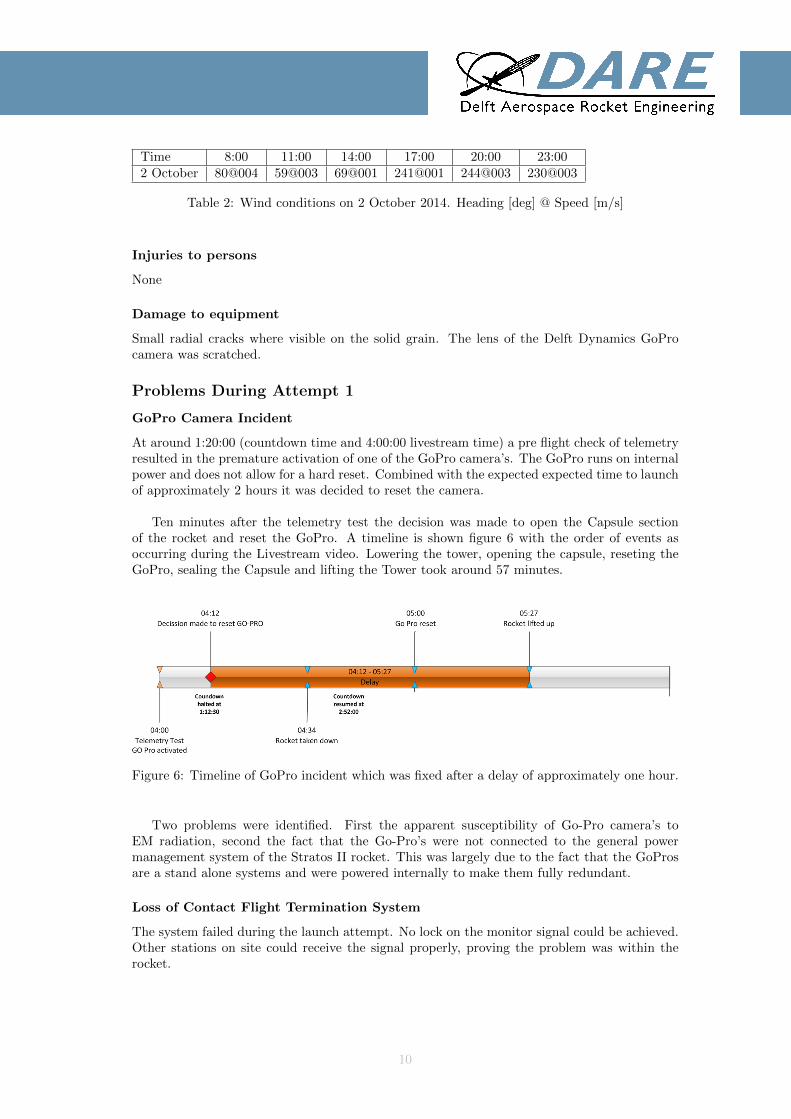
At around 1:20:00 (countdown time and 4:00:00 livestream time) a pre flight check of telemetryresulted in the premature activation of one of the GoPro camera’s. The GoPro runs on internalpower and does not allow for a hard reset. Combined with the expected expected time to launchof approximately 2 hours it was decided to reset the camera.
Ten minutes after the telemetry test the decision was made to open the Capsule sectionof the rocket and reset the GoPro. A timeline is shown figure 6 with the order of events asoccurring during the Livestream video. Lowering the tower, opening the capsule, reseting theGoPro, sealing the Capsule and lifting the Tower took around 57 minutes.
Figure 6: Timeline of GoPro incident which was fixed after a delay of approximately one hour.
Two problems were identified. First the apparent susceptibility of Go-Pro camera’s toEM radiation, second the fact that the Go-Pro’s were not connected to the general powermanagement system of the Stratos II rocket. This was largely due to the fact that the GoProsare a stand alone systems and were powered internally to make them fully redundant.
Loss of Contact Flight Termination System
The system failed during the launch attempt. No lock on the monitor signal could be achieved.Other stations on site could receive the signal properly, proving the problem was within therocket.
10

Check Valve Oxidiser Leak
After disconnecting the oxidiser fill umbilical, the check valve failed in blocking reverse flowout of the tank, leading to a constant flow of nitrous oxide out of the tank. After a short time(order of magnitude: 15 minutes) the oxidiser level was too low to have assured nominal motorperformance, compromising the mission.
Inaccurate Load cell reading
The load cell reading the rocket weight showed significant inaccuracies and hysteresis effects inthe order of 20kg (equivalent to 25% of the oxidizer weight).
No Direct Visual Feedback of the Rocket State
Launch control did not have a direct feed back of scheduled and unscheduled events such as:umbilical disconnect, white vapour exiting BV, white vapour exiting fill line, white vapourexiting dump valve, ignition, other unexpected behaviour. This added delay and uncertaintyto the decision making process on the spot.
Operational Communications
Cell phones where used to communicate with the off-site telemetry station from the controlroom. For communication from the mission control to the rocket operation center a porto sys-tem was used.For a full overview of the communication see figure. 7 Several glitches and largeamounts of noise were observed during operations with the porto system. Determined factorswere the lack of line of sight which required Robert to walk to the roof of Mission Controland interference between porto system and Radar systems on the base during final minutes ofpre-launch operations.
The porto system was for the second launch attempt interchanged with an ethernet connectionusing Skype.
Figure 7: DARE Communications diagram. INTA posts and communication links are notshown.
11

Bad Radio Connection Between Launch Control and Mission Control Radio com-munication between Tobias Knop and Robert Werner was only possible if both people left theirposts. This compromises their overview of the situation and posed a safety risk.
Synchronized countdown with Launch Control At Launch Control there was no count-down clock, although sequenced events were dependent on it. A lot of called out times divertedfocus from other important tasks.
Investigation
Flight Termination System
The first possible reason for the failure of this system was interference from the rockets owntelemetry system. As soon as the telemetry system was turned on, the flight termination systemfailed.The second possible reason for the failure of this system was found to be an error in the preamplifier circuit. This error severely worsened the common mode rejection and linearity of theamplification, resulting in a sine wave being transformed to a square wave. At low signal powersthis made the circuit fail at detecting the termination tones.
12

4. Failure Analysis Launch Attempt 2
Factual Information
Key Personnel Attempt 2
The crew of the test and their function are listed below.
Name Role location Organi--zation
Time atorgan-isation(years)
Jose Ramon Gar-cia Santos
Aerial Safety Offi-cer
Mission Control INTA n.a.
Robert Werner RSO Liaison Mission Control DARE 4Rob Hermsen Flight Director Mission Control DARE 5G.H. Visser Communication Mission Control DARE 6Ralph Huijsman Communication Mission Control DARE 4Antonio Luna deGracia
Ground Safety Of-ficer
Hangar INTA n.a.
Jose Maria CastroCeron
Ground SystemsTechnician
Hangar INTA n.a.
Tobias Knop Ground Safety Of-ficer
Hangar DARE 4
Stefan Powell Test Engineer Hangar DARE 4Jeroen vanStraten
Rocket Interface Hangar DARE 5
Douwe van Willi-gen
Rocket interface Hangar DARE 3
Maurits van Hei-jningen
Telemetry Offsite Post DARE 5
Nils von Storch Telemetry Offsite Post DARE 4Radu Florea Telemetry Weather Station DARE 1Johannes Ehlen FTS Operator Optronics Control DARE 3
13

Timeline of events
Table 3
ID Start ofevent
Event dura-tion
Event Description
LA2-01 N.A. 2m Rocket was transported to launchpad.LA2-02 N.A. N.A. Function testing commenced on the launchpad.LA2-03 N.A. N.A. During function testing, anomalies where observed
in FTS signal.LA2-04 N.A. N.A Lower part of the rocket was disassembled.LA2-05 N.A. N.A. FTS was taken from the coupler compartment, forc-
ing the crew to turn the main valve assembly to makeroom.
LA2-06 N.A. N.A. FTS electronics board was swapped.LA2-08 N.A. N.A. The FTS assembly was placed back into the coupler
compartment.LA2-09 N.A. N.A. Pressure test was performed and a leak between
bulkhead and MV was observed.LA2-10 N.A. N.A. RSO declared wind was getting worse, making sec-
ond launch window unusable.LA2-11 N.A. N.A. Based on unavailability of second launch window, it
was decided to go ahead with attempt despite theleak.
LA2-12 N.A. N.A. LOXEAL was put on leak in an attempt to slow theleaking
LA2-02 N.A. 45s Rocket is slid in the tower railLA2-13 N.A. 1m30s Tower is erectedLA2-14 N.A. N.A. Motorbay temperature sensors clipped at a reading
of 0 degrees (indicating leaking of oxizer)LA2-15 N.A. N.A. Due to this cooling, procedures were altered to
launch ASAP, omitting tank heatingLA2-16 N.A. N.A. Upon umbilical cutting, FV1 was still open, causing
the N2O cylinders to empty and the filling line toswing around
LA2-17 N.A. N.A. at T-0, rocket did not take offLA2-18 N.A. N.A. MV servo was cycled continuously in an attempt to
open the valveLA2-19 N.A. N.A. IV was kept open to keep the motor hotLA2-20 N.A. N.A. at T+15, capsule was disarmed to prevent deploy-
ment due to timers, effectively aborting launchLA2-21 N.A. N.A. N2O was vented trough BV, IV and leaks
Meteorological information
The ambient temperature was approximately 35 degrees Celsius. It was slightly cloudy.
Time 8:00 11:00 14:00 17:00 20:00 23:003 October 34@001 66@002 147@001 228@003 248@05 258@004
Table 4: Wind conditions on 3 October 2014. Heading [deg] @ Speed [m/s]
14

Injuries to persons
None
Damage to equipment
Two of the fins of the rocket got damaged by the filing hoses. The filling hose is damaged aswell. Next to this, the umbilical cable was burned through by the engine flame and the enginecontrol systems suffered from frost damage. However the issues found of the communicationsystems during the attempt on Thursday were resolved.
Problems During Attempt 2
Feed system The main valve did not open according to the launch sequence.
System communication During the later parts of the launch sequence the communicationwith the engine control systems became sporadic. After the launch attempt the umbilical cablewas exposed to the flame from the engine, causing issues with the engine control systems.
Fins were damaged by slingshotting fill umbilical The nitrous oxide fill umbilical wascut without closing FV-1 and without depressurizing the line first. This caused all five nitrousoxide cylinders to be emptied through the cut fill umbilical. It was slingshotting around,damaging two fins, before it got stuck between the ground and a leg of the launch tower, whereit remained until all nitrous oxide from the filling cylinders was vented.
Nitrous oxide leak into feed system compartment Due to an anomaly in the feed systemliquid nitrous oxide was venting into the feed system compartment, slowly depleting the loadedamount and cooling down the feed system compartment.
Constant loss of oxidizer through check valve after umbilical disconnect After dis-connecting the oxidizer fill umbilical, the check valve failed in blocking reverse flow out of thetank, leading to a constant flow of nitrous oxide out of the tank. After a short time (or-der of magnitude: 15 minutes) the oxidizer level was too low to have assured nominal motorperformance, compromising the mission.
Main valve did not open At T=0s the main valve did not open. Even after cycling theactuator multiple times in the hopes of getting a mechanical jamming ”unstuck” the valve didnot open.
Bad radio connection between Launch Control and Mission Control Radio commu-nication between Tobias Knop and Robert Werner was only possible if both people left theirposts. This compromises their overview of the situation. A constant video Skype connectionwas established, which was problematic as Tobias Knop was connected to Geert Henk Visserand not to Robert Werner. The non-selective transmission lead to a lot of distraction and didhardly aid the communication process.
Synchronized countdown with Launch control At Launch control there was no count-down clock, although sequenced events were dependent on it. A lot of called out times divertedfocus from other important tasks.
General tiredness of personnel Due to the late night debugging, related to launch attempt1 and previous weeks of sleep deprivation, nearly everybody’s focus was significantly compro-mised, which showed by slower than possible working pace, avoidable and stupid mistakes,tense, at time almost aggressive, communication between team mates, etc.
15

Operational Communications
Cell phones were used to communicate with the off-site telemetry station from the mission con-trol. For communication from the control room to the hangar a Skype video conference systemwas set up .
Investigation
After arrival in Delft, the motor section was disassembled to investigate which interfaces whereleaking.
Upon disassembly of the bottom engine bulkhead the following items were discovered:
• MV assembly was loosely in the bulkhead it could be turned by pushing against the servo.• Inner bulkhead has some sand like deposit in it (grey and brown). Also inside the valve
(grey and brown) and in the tank (only grey) some of the residue was found. The residuelooks similar to residue previously observed with nickel plated steel pieces in the feedsystem
• Small amounts of ball bearing grease was found on the casing and inlet fitting of IV, itwas also found on the bolt side of the inner O-ring groves of the bulkhead
• The Teflon crush ring between the check valve fitting and bulkhead is abnormally ex-truded.
• Sealant ring on the tank pressure sensor was missing.• Batteries were missing (note: batteries and several other electronic components were
removed before transport out of safety concerns).• Manually operating the MV was successfully performed without anomalies. Some N2O
was still entrapped in the valve and escaped upon opening indicating there was no leakagein the valve.
After the bottom bulkhead was disassembled from the main tank, it was put into the testtank (previously used for filling N2O test) and an 8 bar compressor was connected to it to leaktest the bulkhead and feed-system. The following results were found:
• Filling line to check valve was leaking heavily.• Check valve to bulkhead was leaking heavily under the seal.• Main Valve to bulkhead was slightly leaking under the Teflon seal.• Main Valve to duty seal was leaking.• Check valve it self was leaking heavily.• The pressure sensor was not leaking.
16

(a) Nozzle after attemp 2 (b) Nozzle and mixer after attempt 2
(c) Motor bay section after dissasembly(d) Bottom bulkhead assembly after taking it out of thetank
(e) Inside view of tank, notice the residue onthe bottom
17

(a) Inside view of bottom bulkhead, notice thebrown residue
(b) Bottom bulkhead without electronics
(c) Damaged seal under check valve(d) Leakage trough damaged seal under checkvalve
Figure 9: Dissassembly of the motor section
18

5. Additional Problems Encountered
An overview of additional and more general problems/issues encountered during the launchcampaign is presented in this section.
Miscomunication on No-Fly and Naval Exclusion Zone
At the start of the campaign it was assumed that the no-fly zone was extended to naval opera-tions. During the first meetings with INTA it was explained that a naval exclusion zone neededto be determined at least one week before start of operations and that different restrictionsapplied than for the no-fly zone.
• The neighbouring harbour at Huelva/ Mazagon is excluded from the Naval Safety Zone.• The deadline for announcing the Naval Exclusion zone to the authorities is seven days
before flight operations.
Problems with Local Authorities of Off-site Ground Station
The launch crew of the off-site ground station encountered a local police officer who questionedthem on what they were doing. Although the crew did nothing illegal, the fact that foreignerscarrying around large radio equipment caused some suspicion from the local police officer. Thecrew carried no documents from the Spanish government explaining their what they wheredoing. This caused some confusion and hindered the crew in their operations.
Confidence Level of Technical Subsystems
Due to budget and time constraints, a lot of subsystems on the rocket where did not demonstratetheir full functionality before the launch campaign, resulting in a low confidence level of thecrew in the subsystems. An overview of systems that where not fully demonstrated is givenbelow:
Electro-Magnentic Compatability The electronic subsystems, including the FTS, wereonly tested on EM compatibility on a low power setting. This was done because there wereworries that if these test where performed with full power setting in the Netherlands, we wouldbe in violation of the regulations of the Agentschap Telecom. This turned out he be a problemsince the compatibility problems did not show up during the low power setting tests but didshow up during the launch attempt when all subsystems operated on full power.
Capsule Leak Tightness After launch it is expected that the rocket will float on the oceanfor at least an hour before it is recovered. The capsule was not tested for long duration leaktightness.
Fin Sizing The fin design was validated using missile DATCOM. There is however someuncertainty how well missile DATCOM takes into account the boundary layer effects over thefins. No proper analysis was done on the boundary layer effects around the rocket. MissileDATCOM, the tool used to generate aerodynamic tables, does take into account boundarylayer effects but this tool is only meant to be only used for preliminary design and its estimateson boundary layer effects may not be accurate. This could potentially lead to an under stablerocket.
Vibration Resistance of Critical Subsystems Prior to launch, a number of critical sub-systems where not tested under realistic vibrational loads. These systems are the clampbandseparation system, the Flight Termination System, the Motor Control Unit and the CapsuleElectronics Stack.
19

Visibility and Attachment of FTS Antennae There is some worry on the visibility ofthe FTS antennae during flight. They might get obscured by the fins, which would cause aunwanted launch abort. Also, the attachment of the antennae might not be strong enoughduring the supersonic phase of the flight.
Load Bearing Capability of Bolts in Parachute System The bolts that mount theparachute system to the rocket have not been tested under a realistic shock load condition.
Residual strength of dyneema wire in clamp-band system The dyneema tensioningwire that holds the clamp band together during the first stages of flight is pre-tensioned to anunknown amount. As a consequence, the residual stress is unknown and may differ from thestructurally tested assemblies.
Kalman Filter and GPS sensors The Kalman Filter and GPS sensors have not beensuccessfully demonstrated up to yet. If these systems do not function as they should they willendanger successful recovery of the rocket after launch.
Simulation Imput Parameters Input data for the trajectory simulation was partially un-verified. Most mass properties, thrust profiles, misalignment estimations, were based on onlyrough measurements and calculations. Additionally, no variance on these values was given. Theeffects of vacuum on the engine thrust was also not taken into account properly.
• No verified (certified) data was available as input to the simulations during the campaign.• Sensitivity parameters were only estimates.• Motor performance was not corrected for altitude.
Miscomunication on External Insurance Requirement
In the period before the launch campaign there was a misunderstanding between the Stratosteam and INTA about the required insurance. The Stratos team was under the assumptionthat INTA would arrange all the required insurance including damage done to external partiesoutside of the INTA base and safety zone. However, it turned out that this had to be arrangedby the Stratos team. When this was finally established, both INTA and the Stratos team hadno clear idea how to tackle this problem. This caused a lot of stress and uncertainty. In theend this problem was solved by the TU Delft board of directors.
Presence of Unauthorized and Unneccecary Personel in Control Room
Mainly during launch attempt 2 a lot of unauthorised and unnecessary personnel was presentin the launch control room. This overcrowdedness made the countdown more chaotic and puteven more stress on the essential crew. This should be prevented in the future.
Misfire Procedures and Oxidizer Dumping
The procedures regarding a misfire proved not to be adequate. Typically, for solid rocket mo-tors, the worry exist when a misfire occurs since the solid propellant may ignite later withoutwarning. This problem does not exist for a hybrid and hence the misfire procedures only incor-porated dumping of the oxidizer. However, during attempt 2, the decision was made cycle theservo in the hope that the rocket would still take off. This however induces the risk that thevalve will only partially opens and causes the rocket to lift-off with insufficient velocity causinga loss of hardware. This decision could be made since the misfire procedures did not take intoaccount this situation.
Related to this problem is the issue of oxidizer dumping in case of a launch abort or mis-fire. Currently the oxidizer can only be dumped trough the bleed valve, which would take in
20

excess of 4 hours in case of a full tank. To quicken up the dumping, the oxidizer needs to bedumped trough the combustion chamber. This is undesirable because the paraffin in the fuelcould absorb some of the oxidizer which in theory leads to a combustible mix.
FTS Communication Problems
As the FTS frequencies designed for the rocket were not directly compatible with the FTStransmitter used by INTA (the transmitter could not operated at the exact frequency requiredas its step-size was to large). A transmitter system had to be improvised on site. For that amodified radio was used. The transmitter was integrated into an amplifier/antenna system oneof the INTA optronics platforms. The IRIG audio signals (Monitor, Arm and Terminate) weregenerated by a software running on separate laptop (see figure 10). That was stationed in theoptronics control container and connected to the transmitter in the platform via 3.5mm audioand COAX cable. The software was operated by DARE personal and the transmitter (carrierwave) could be activated and deactivated from the optronics control board (operated by INTApersonal).
Figure 10: Layout of the FTS Audio Tone Generation Software
This system had multiple general problems:
• The system had too many single failure points that could have lead to a termination ofthe flight, such as: accidental unplugging of laptop audio cable, accidental shut down orhibernation of the laptop, crash of laptop and/or software, accidental pressing of buttonson the laptop, accidental deactivation of carrier signal (the button for this was an un-protected and unmarked button on the optronics control board, that would usually havea different function), depletion of the transmitter battery and failure of transmitter andtransmitter connections due to high g-loads in the rotating platform.
• The transmitter could only transmit for a limited time of 10 minutes after that it had tobe reset by resetting the carrier.
• During attempt one there was nothing to verify a proper transmission of the signal. Thiswas fixed during attempt two by listening to the signal via an extra radio setup in theoptronics control.
• It seemed to be difficult to find the correct amplitude (volume) settings for the transmitter.If the volume was too high the receiver would clip and if was to low the reception was
21

unstable. Multiple attempts (tests) were made to determine a good setting. Resultswere however always different. Before the second launch attempt a setting of 5% wasdetermined, when activating the FTS before launch initially no signal was received bythe rocket. The volume had to be double in order for the rocket to have good reception.The signal also seemed to be very noisy (compared to earlier) when listening to it on theexternal radio.
• During the countdown a weather balloon was launched, the weather balloon was trackedby the optronics. During that period no FTS operation (nothing that would requirethe rocket to receive the Safe of Arm signal) could be performed. This proved to besuboptimal during countdown and testing.
• Communication between DARE FTS operator and mission control proved to be difficult:If the DARE personnel in mission control wanted to request a change in the FTS transmis-sion, that had to be relayed to the INTA personnel (RSO) who would than communicatethat to the optronics control via the INTA voice loop (in Spanish). The INTA optronicsoperator than had to translate the message back to English for the DARE person operat-ing the laptop. This took quite some time, information got lost as it had to be translatedtwice and it was not possible to verify where the information came from and if it was au-thorized. This was especially problematic during testing an debugging in the countdown.After attempt one this problem was supposed to be mitigated by including the DAREperson in the optronics control in the DARE voice loop, as however the optronics controlwas EMC shielded the DARE porto phones proved to be useless.
22

6. Conclusions
This report described the failed launch attempt of the Stratos II sounding rocket of October2014. The Stratos II rocket was completely developed by students and had an indented apogeeof 50[km]. The launch of the rocket was conducted in cooperation with the CEDEA launchbase of the Spanish Institute of Aerospace Engineering. In total two attempts were made tolaunch the rocket, both unsuccessful.
During the first attempt it became apparent that the check valve between the oxidiser tank andthe filing cylinders was leaking, causing oxidiser to leak from the tank after filling. Further-more the Flight Termination System (FTS) encountered resonance from the transmitters onthe launch base, preventing the FTS to get a lock on the monitor signal. Both problems causedthe abort of the launch attempt. Additionally there were a number of issues in the operationsand communications.
The problem with the FTS were eventually solved. In doing this the tank bottom bulkheadwas accessed a number of times. Since the weather was deteriorating, there was not enoughtime to get this bulkhead out of the tank. Therefore it needed to be accessed from within themotor bay. This caused the main valve to lose it leak-tightness. This caused oxidiser to leakinto the motor bay during attempt two. This leak caused the main valve to freeze which causeda mis-fire.
These problems showcased that all of the rocket subsystems should have been tested beforethe launch attempt. Additionally it showed that the FTS and motor control electronics wherehard to acces inside of the rocket. To prevent the problems encountered during this launchcampaign for future projects a number of recommendations are make in the next section.
23

7. Recommendations
In this section the most important recommendations based on the encountered problems aremade. Goal is to solve all of the problems that were encountered. A division is made betweentechnical changes, operational changes and changes in communications. Furthermore a list ofrecommended tests is pretend to increase the confidence level in the system and to find potentialproblems before the next launch attempt.
Technical Changes
From a technical point of view, there where three major problems. First of all the FTS systemsuffered from interference. Secondly the check-valve in the filling line of the rocket leaked.Finally the electronics in the motor bay are hard to access without taking the bulkhead out.This resulted in the leak between the main valve and the tank bulkhead.
Accessibility of Electronics in Motor-bay
The accessibility of electronics and feed-system in the motor-bay section is currently problem-atic. In the current design, the FTS electronics can only be properly accessed by taking outthe tank lower bulkhead, which is a very time consuming activity. If the FTS is to be accessedwithout taking out the bulkhead, the MV needs to be turned and there is no way to re tightenMV without taking the bulkhead out.
As such it is very important that the accessibility of this section. This can be done bymaking a hatch in the skin or switching the ”skirt” from the tank section to the motor section.A proper analysis needs to be made on what concept will yield the highest level of accessibility.
Filling Line
To prevent leakage trough the filling line it is advised to replace the self build check valve bya commercial one. It is also advised use a servo actuated ball valve instead of a check-valve.This way dumping of oxidizer in case of a launch abort can be achieved in a quick way troughthe filing line.
GoPro Camera
To fix this system several suggestions are made.
• Add RF shielding.• Use a proper camera with circular buffers and proper external interfaces (like a dashboard
camera).
Flight Termination System
The Flight Termination System will have a better demodulator, to demodulate from FM tothe intermediate audio frequency. This will comply to the regular IRIG standards. The tonedetection part has already been repaired and no further changes to that are needed.
The transmitting architecture and operations shall be completely supplied by CEDEA.
In order to gain a better illumination of the FTS receiving antennas on the rocket a relo-cation to the fins can be considered.
To fix this system, the above recommendations need to be implemented. After that the followingtests need to be done:
• Wide band vibrational test.• RF compatibility test between telemetry, video feed and flight termination system.
24

• Range test.• Antenna gain test.
Telemetry
This system worked. However, it would be better to change the operating band of this systemfrom the 434 MHz band to the 868 MHz band, because this is expected to result in lessinterference with the flight termination system and smaller physical antenna size. This smallerphysical antenna size should result in better GPS performance, since components can then beshifted, shielding the antennas from other RF sources better.
Operational Changes
Misfire and Hangfire procedures
In order to avoid confusion in case of a misfire, clear misfire procedures need to be made. Anassessment on the different post misfire scenarios need to be performed to decide what course ofaction should be taken in case of a misfire. Spontaneous decisions shall be avoided by planningout courses of action.
For the possibility of a hangfire (low thrust combustion, no ascent). Procedures and dis-arming protocols shall be made.
Access to control room
The access to the control room shall be limited to essential personnel. This needs to be imple-mented in synthesis with the remaining improvements to not even generate the need of peopleto enter the control room (e.g. due to lack of information reaching critical stations).
Logbooks at Stations
It is advised to have at every station a dedicated person responsible for keeping a logbook ofall the events. This will improve the documentation of data and as such will improve the postlaunch analysis which in turn will be beneficial for future projects.
Sharing digital information across stations
For smoother and synchronized operations general information such as the following shall beshared with all critical stations in real time, with all non critical stations in near-real time:
• Telemetry data• Current checklist point• Countdown clock• Rocket visual feedback
Communications Protocol
To mitigate a lot of the operational problem encountered during the launch attempt severalimprovements are suggested. Problems to be solved are:
• Communication problems between hangar and mission control.• Lack of information for non flight-critical stations of progress of launch.• Create a clear task devision within mission control.• Create a reference timeline of events enclosing all available stations for future analysis.
A brainstorm came forward with two communication loops and a list of required stations. Anoverview is shown in figure 11. The system shall be either internet based or be covered bybetter quality porto systems.
25
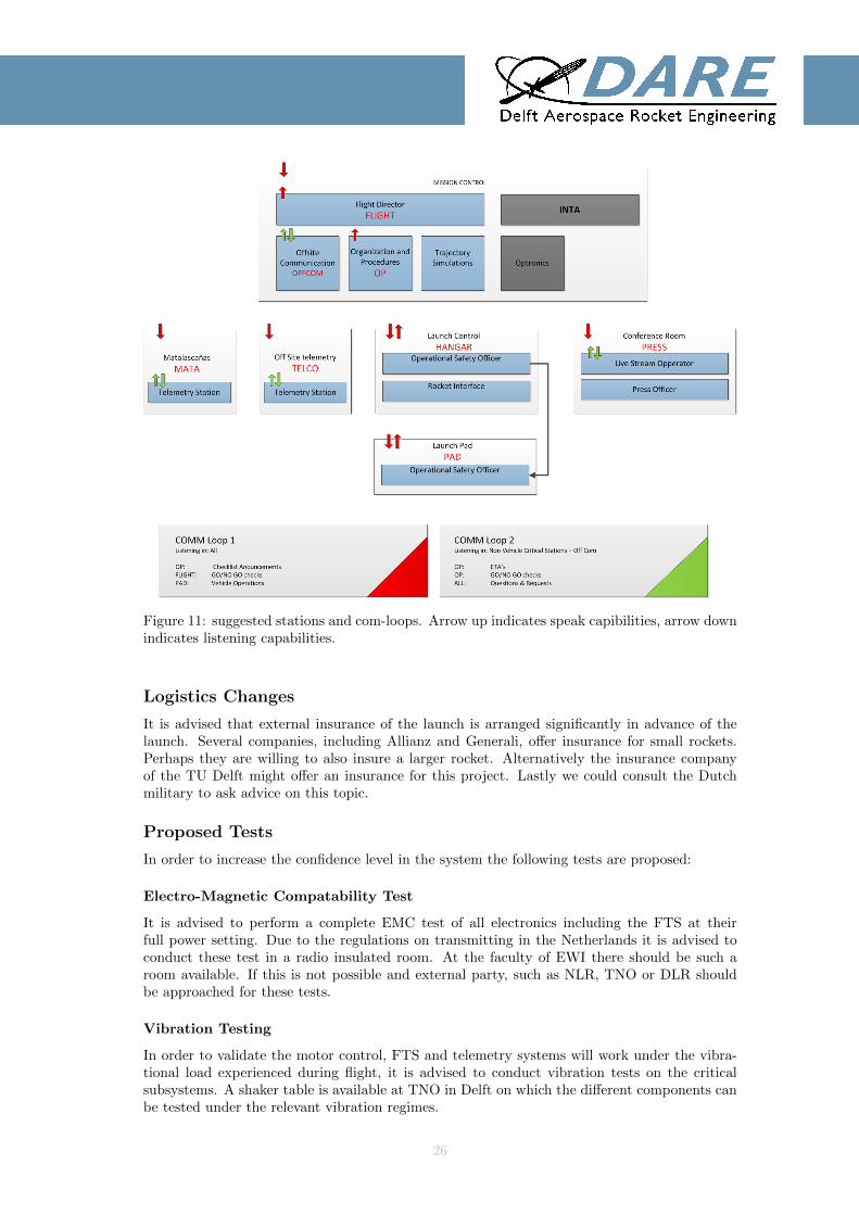
Figure 11: suggested stations and com-loops. Arrow up indicates speak capibilities, arrow downindicates listening capabilities.
Logistics Changes
It is advised that external insurance of the launch is arranged significantly in advance of thelaunch. Several companies, including Allianz and Generali, offer insurance for small rockets.Perhaps they are willing to also insure a larger rocket. Alternatively the insurance companyof the TU Delft might offer an insurance for this project. Lastly we could consult the Dutchmilitary to ask advice on this topic.
Proposed Tests
In order to increase the confidence level in the system the following tests are proposed:
Electro-Magnetic Compatability Test
It is advised to perform a complete EMC test of all electronics including the FTS at theirfull power setting. Due to the regulations on transmitting in the Netherlands it is advised toconduct these test in a radio insulated room. At the faculty of EWI there should be such aroom available. If this is not possible and external party, such as NLR, TNO or DLR shouldbe approached for these tests.
Vibration Testing
In order to validate the motor control, FTS and telemetry systems will work under the vibra-tional load experienced during flight, it is advised to conduct vibration tests on the criticalsubsystems. A shaker table is available at TNO in Delft on which the different components canbe tested under the relevant vibration regimes.
26

Shock Testing in Parachute Connections
It is advised to subject the critical connections of the recovery system to realistic shock loadvalues to validate their load carrying capability. Investigations should be made on where suchfacilities exist. It is expected that the required equipment is present at either the aerospace orCivil Engineering faculty.
Long Duration Leak Tightness of Capsule
In order to validate that the capsule will actually protect the electronics from the sea waterbetween landing and recovery, a mock-up of the capsule with the same sealant, should besubjected to long duration exposure to water. It needs to be taken into account that thebuoyancy characteristics of the mock-up capsule should match the one of the actual capsule.
Simulation Improvement
Subsystem teams have to put more effort in estimating input data for the simulation. Calcula-tions for masses, inertia, thrust (misalignment), ect. have to be properly done and estimates ofthe variance of these parameters must be given. Proper research has to be done on how muchchange is expected for the thrust profile at higher altitudes. Also the boundary layer effectshave to be investigated, by means of CFD analysis.
Motor Test
To this date, the motor has not demonstrated its performance over the intended burn duration.Therefore, if the financial situation allows for it, it is advised to perform another motor testcampaign to demonstrate the performance of the propulsion system.
27