Fore-w-ord - Mechanical Music Digest - Home · Amphion Piano-Player Company SyrCUUJI!!, NI!!W York...
33
Transcript of Fore-w-ord - Mechanical Music Digest - Home · Amphion Piano-Player Company SyrCUUJI!!, NI!!W York...


Amphion Piano-Player CompanySyrCUUJI!!, NI!!W York
Fore-w-or dI .
t:'OR more than twenty years the Amphion Companyr has specialized in the production of strictly highgrade piano player actions.
During this time the foremost engineers of theindustry ha ve con tribu ted their undivided efforts toper fectin g the company 's product . The most modemequipment and methods have been employed. Materia ls of the highest possible quality have always beenused. The company's product has always been soldonly to manufacturers of fine pianos. and AmphionActions are not to be found in pianos of inferior orquestionable quality.
A distinctive feature of the Arnph ion action over allothers is the accessibil ity of every work ing part and theease with which any pa rt of the player or piano actionmay be reached for adjusting, cleaning, or re-conditioning, as well as for tuning the piano.
T he Amphion action is noted also for its ease ofoperation and for the perfect control of expression atthe command of the opera tor.
This little booklet is intended to convey in clear andsimple language the work ings of an Amphion Action sothat anyone may understa nd it. I t shows how to carefor the act ion so as to obtain the best results from thepiano . A lit tle care will add years of life to the instrument.
To prospect ive pu rchasers of a player piano or to theowner of a piano equipped with the Amphion AccessibleAction , this book is sure to be of value. It should be .,g-~:;....read carefully and kep t for future reference . ~_'.:;"
~~1iiit~~,

Contents
1Making Music from a Paper Roll
Unskilled Hands Produce Music-The PlayerPiano Roll-The Player Action-The AmphionAccessible Action-Its Distinctive Advantages
Pages............................... 5 to 8
2Interesting Features of the Amphion Accessible
Player ActionGeneral Construction-Top Action AssemblyDecks and Valves-Valve Constructton-c-SpcolBox-Transmission-Air Motor-Air MotorGovernor-Gate Box-Vent Block-The Bellows-c-Sustairung Pedal Pneumatic-Rail LiftingPneumatics
Pages . 9 to 24
3
How to keep an Amphion Player Action inPerfect Working Order
Useof Tracker Pump-Lubrication-Valve Functioning-Automatic Tracking-Brake Drum andMusic Roll Brake-Care of Air Motor-Air MotorGovernor-Tempo Regulation and Governor Adjustment-Bellows Care and Adjustments
Pages 25 to 32

1
Mdkin~ Music from
a Paper Roll
o

\
AWOMAN who has never been musically trained sits atthe piano and brings forth from the instrument masterlyinterpretations of great music. A man who does not know
one note from another makes his piano produce old time melodiesor lively popular music as capably as the accomplished musician.
What is the mystery behind this concord of harmony fromhands unskilled in musical performance? Just a perforated paperroll, together with the mechanism of the player action installedwithin the piano.
So swiftly have science and invention progressed in the pastquarter century, that we hardly stop to marvel over the wondersof the mechanism that produces music from the piano with theaid of the perforated roll. In the roll is music ready to bereleased. Within the piano is the mechanism, the player action,which enables the operator to release the music, and with butlittle practice or experience, to endow it with his own moods, feeling and expression, imparting to it in fact his own interpretation.
The character of the interpretation that it is possible toobtain depends upon the design and construction of the playeraction, and upon the tone and other intrinsic qualities of thepiano. The finest piano equipped with an inferior and nonresponsive player action cannot possibly yield good music anymore than such a piano could yield good music at the hands ofan inexperienced pianist. Neither can good music be producedwith the aid of the finest player action from a piano of poor toneand inferior quality.
To produce good music and to provide lasting satisfactionthe player piano must consist of a combination of a high gradepiano with a nicely balanced, well constructed, and responsiveplayer action. In this regard the Amphion Accessible Actionleaves nothing to be desired. It stands apart from all othermechanisms of its kind in the perfect balance of its design, thematerial and workmanship employed in its fabrication, and itsresponsiveness and ease of operation. Moreover, this action isnot to be found in pianos of questionable quality; therefore apiano equipped with it is sure to be a good piano.
Let us mention a few distinctive features of the AmphionAccessible Action.
6

EASE OF OPERAT ION
In a foot pump player piano the pumping characterist ics areof utmost importance. T he pumping may be too heavy or toolight , too rapid or too slow, according to the design of the bellowsor pumping elemen t .
The bellows of t he Amphion Act ion has been perfectedthrough years of painstaking development to the point where itoperates with perfect smoothness and precision, providing for theinstantaneous accenting of any select ed note or group of noteswithout carrying over the accenting intensity to succeedingnotes. Thus the most delicate shading and phrasing can beimparted to the music and the greatest degrees of cont rast ofwhich the piano is capable can be developed without consciouseffort on the part of the operator.
T he speed of pumping and pressure of t he pedals underfoot can be varied within wide limits by simple adjustments tosuit the pleasure of the individual.
ACCESS IBILI TY
All mechanisms require occas ional attention and reasonablemechanical care if they are to yield the best service.
The player action of a player piano is no exception to thisrule ; therefore accessibility or lack of it to the player act ionelements is an important feature in determi ning the ultimatesat isfaction that the player will give to its possessor.
The Amphion Accessible Action is unique among mechanisms of its kind in providing the maximum degree of access ibi lityto every working part. Every part of this action is instantlyaccessible for examination, cleaning, and reconditioning. E verypa rt is replaceable with a minimum of effort and expense, shouldreplacement become necessary.
Adjustments to the player action may be made at all pointswithout disconn ecting tub ing or otherwise disturbing theinstallat ion. The piano may be tuned and regulated without anyint erference from the player.
In genera l the Amphion Accessible Act ion provides everyfeatu re of interchangeability of parts and every convenience formaintenance to be desi red , and in t his respect differs radi callyfrom most other apparatus of its kind.
7
MUSICAL QUALITIES
The quality of music obtainable from most player pianosmust not be confused or associated with that which can beobtained from the piano equipped with an Amphion PlayerAction.
Music is a thing of mood and impulse, and in the design andconstruction of the Amphion Action this point is always heldclearly in view. Elaborate and distracting control apparatus isavoided. Instead, there are employed principles of design thatyield through the perfection of their well balanced charactercomplete freedom of operation with spontaneous and naturalreflection of each passing mood and fancy of the operator.
Thus with the Amphion Action the player pianist mayexpress musically every impulse and feeling as readily as hecould through highly trained fingers, were he an accomplishedmusician.
QUALITY AND DISTINCTION
It is perhaps needless to state that a player action in whichall of these most desirable features are combined is not the leastexpensive apparatus of its kind to manufacture.
Yet a good piano equipped with the Amphion AccessibleAction costs the purchaser little, if any, more than the same pianoequipped with a commercial type of action; and in the end whatever slight extra cost may be involved is returned many timesover in superior service and lasting satisfaction given to theowner.
From the fact that this action is not used in pianos of cheapmanufacture or questionable reputation, it follows that theAmphion equipped player piano always represents a combinationof quality, distinction, serviceability, and value that cannotbe excelled.
The distinctive mechanical features of the Amphion Accessible Action are set forth on the following pages.
8

lnterestlnq Featuresof the
Amphion AccessiblePlayer Action
"\
~."""'~'i.~I~' =u

-_.
_ ,_ ... .,.,_ '010
......_L' __ . " T'e
(: _ . ~o~ .... , I O ..~. _ Sun~ , .. ,_ .. .. ., A ~"
....~ .. ..~"C . - - ---- -1-
F I GUR E I
FRON T V Ili:W 0 .. AMPH.ON ACC l1;SS'BLE A CTION S "" O W I N G LocA T I O N 0 ..PRINCIPAl. P A R T S . T ... &: ACTION I S S H O W N M O UNTED IN A S KEL.£TON
P I A N O FRAMe:
. T _F .
T,.... ,.oT."""",, .."
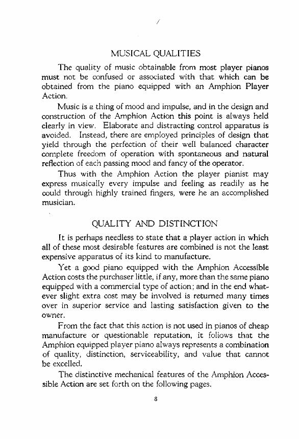
F IGURE 2
R E"'R VIEW OF AMPHIO ... A C T IO N IN SKEL.£TO... FR... ....E .SHOWI...G POSITIONOF STRIKING PNEU ....... TICS "'''10 STR I K I N G FI NGERS
..w.....,.., ~1l0.....
~llw T'C

. r'.."......., .._ N n ' _ k " a ...
••"''''HO..,....~".
F IG URE 3
T Op A CTION ASSIEM e r..Y S HOW ING S POOr.. BO X TIPPlEe "'ORWARO
THE TOP ACT iO'.; ASSE.' IBLY
FOR tuning the p iano and regulating the piano action the spool boxmay be tipped forward as shown To accom plish this, remove onescrew a t each end of the spool box boa rd an d disconnect the air mo tor
supply tube ; then rotate the spool box on the hinges at the end of thespoo l OOX board. supporting it from the piano keybed with a musicroll OOX
The LOp action is supported on the chee ks of the piano by levelingscrews at the ends o f th e dec ks. providing qu ick and accurate means ofadjust ing its gene ral posi tion with reference to the piano act ion.
Deck support bolts at the sca le breaks insure rigidity and st iffnessof the deck structure. When changes are made in the top acti on posit ion by means of the level ing screws at the ends o f the deck s. the decksuppor t bolts shou ld also be adjust ed to ma intain pro per alignmentof decks.
Individual adjustments of striking fingers LO secure contact betweenthese members and the p iano action wippens are made bv turn ing theadj ust ing button screw proj ect ing through the top of each tmger. T hesescrews may be reached and the adjustments made without d ifficultyeither with the spool box in its normal posuton or rotated forwa rdas shown

SPOOL eOxeO~"o
IR OUT 'N <;
H 'N<U'
" ......v" 5TVO~ND NUT
UNITV~LV" SP"' N<; _
0"001<5T""<l N<1
"'NO'''''
5T"' ''' ' N <;~N£U"'~ T'oo
F IGURE 4
SECTI ONAL VIEW O F D EC K S A N O VALVES
THE DECKS
ln this illustra t ion the tubing at the rear of the action to the t rackerbar has been removed.
Each deck carr ying: its striking pneumat ics and valves to ope ratethem is a separate member of the tOP action assemb ly.
Each valve is a separa te, interc hangeable unit, instantly removablefrom the deck by releasing the nut which ho lds its spring.
The jo ints between uni t valves and decks are ma intained tigh t bythe hea vy spring pressure applied to the va lYeS .
These joints are not subjected to mechanical stresses resulting fromthe operat ion of the striking pneumatics.
"

"D"'H"' ~" TS C"EWS
n "'M'"'' P" E" ...~ T'C, ,,
C<>"PE"S~T'''GW .....E ..
DEeM I3<>LT
FIG URE S
RE A R A N D E ND V I E W OF DECKS, PNEU M ATICS ANDSTRIKING F INGERS
THE DECKS
The three decks are assembled together at each end by means of asingle bolt ; thus they read ily can be taken apart when necessary.
A heavy rubber washer is employed under the head of the deckassembly bolt to compensate for dimensional changes in the wood of thedecks and to ma intain tightness of the deck joints . 1'\0 oth er jo ints areinvolved in the st ructu re of the top act ion, therefore difficulties due toleakage are minimized.
If leakage does develop a t these joints it ma y be eliminated simplyby tightening the end bolts, t he slot ted heads of which are exposed whenthe spool box is tipped fo rward.
The lengths of the wire fingers between pneuma tic tips and strikingfingers are fixed. T here are no adjustments to make and no nuts tostr ip from threaded wires.
14

s.c~to.. ".Ut< , ~ " ~ L'• ..... . "" .LV
P"",,"~T' C
~".
OIJTS' ''."~LV. S.~T"
F IGURE 6
D e: T AIL.5 O F U N IT VA LVE CO... ST"l UCTION
THE UN IT VALVE
U..,T v ~"'v•.... ... . LOU
Eve ry valve assembly of the action is an interchangeable, demountable unit . Each unit represents a complete self contained valve assembly.
T he valves or moving pa rts of the assembly are simple in structu rehaving no meta l stems to corrode and stick in their guides.
The inside valve seat, against which the valve rests at all times whennot in actual operation, is a moulded part of special composition ,unaffected by climat ic conditions , and proof against corrosion.
The outs ide seat or valve cap is of nickeled brass assembled as apress fit into the valve chamber of the unit and cemented in posit ion.
The assembly of valve cap into valve body is mechanically accomplished in the factory by automatic machines, which simultaneouslymake the assembly and adjust the throw or motion of the valve. Thusthe human element is eliminated from the operation of set t ing thevalves, and all valves are adju sted with utmost precision and regular ity.
The vent cup is in the contact face of the valve assembly, and isreadily made accessible for cleaning by removing the valve from the deck.
"

Ro~ ~,", ,,,us,,,,,, Ro o
SCI,U,,,,',,," PE"A~
LEv'"
S UsTA' ''' NGPEDAL SW ' TC H
IOo~.."'''JUn''''GP"'~U"H'C
p .."""r ~ B~U ' ''GA" " Sp l..O~~
Rou ...D JUsTE_V.~V~
S O"OO~ il EA.. . .."AN D SP"''' L ~
T .." ,<,
' '''O'C HO'' 10,,0
A"' '' p"" NTO"
FIG URE; 7
SPOOl. B OX A,NO RE " A,T E O PA,RTS
THE SPOOL BOX
The tracker bar is of solid bra ss. not a shell, therefore free from anytendency to warr or get out of a lignment. The ports or openings in thebar are accurately formed and perfectly spaced.
Automatic t racking of the music sheet is accomplished by movingthe music roll bearings in their spind les by means of the roll adj ustingpneumat ic, which is t he simplest apparatus of its k ind in existence, conta ining no complicated mechan ical parts to get out of adjustment , novalves to get out of order, and no screens or vents that require cleaning.
The transposing apparatus is extrem ely simp le and pos it ive in itsaction, t ransposit ion of the music being accomplished simply by movingthe small knob from one position in its index plate to another , whichact ion moves the transposer lever and shi fts the tracker bar.
All spindle bearings a.e amp le in si: e and readily lubricated. T heyare accurately positioned. so require no provision for adj us tment.
I.

,•
\,
T ' .. 'O ..GI ..
T .. . ... .. '..,O..l.C'o C"
T U ..S "''''O.."h e" ,-••".
F 1G U P!ll: I
T fII A N SM I S S IO N A ND REL....TEO P .....T S
17
.~
A OI UU'NG Roo
II ......~AO, uSn '"
.......K C"u......0 '!!i_OCKEr
T ' U IO.., ~
T'U N$ "'U''''':l"'H $PflOCK n

.-TRANSMISSION AND RELATED PARTS
The transmission assembly is an interchangeable unit readilyremoved from the spool box by loosening two screws. rcs die castframe provides liberal bearing surfaces for its two shafts with convenient oil holes for the lubrication of bearings. It is extremelyrugged in construction and not subject to disorder. At the sametime it is constructed with watch-like precision and operates with aminimum of noise.
A most notable feature of this transmission is that its construction does not require the alternate engaging and disengaging of itsgears. The large gearand pinion are always engaged and thereforethere is no wear or burring of gear teeth incidental to any gearshifting operation.
Pin clutches of simple construction, with hardened steel pinsaccurately" formed to facilitate shifting and to minimize wearrelieve the gears of any stresses Incidental to reversing the directionof travel of the music sheet.
The arrangement of transmission clutches is better shown by thenext illustration, Figure 9. In it the transmission lever is shown in
. the "play" position with the lower or take up spool clutch engaged."Shifting the lower end of this lever to the left disengages the spoolclutch and engages the reroll clutch. At the same time the upperend of the lever lifts the music spool brake stick from the drum andpermits the music roll to turn freely.
"
18

T~ .. " ~ ... ' U 'O..P , .. 'O ..
T.. ~ r_.u p
~ ~OO. C LU 'CH
F IGURE 9
AIR MOTOR
THE AIR ~IOTOR
The Amphion Air :\ Ioror is constructed with six power pneumaticsthus insuring perfect smoot hness of operation"
For the operation of the six pneumatics only three slide va lves areemployed instead of six"
The valve plates are met al of a specia l composi tion ground to a tru eflat surface , This ma terial is not subject to corrosion, will not warp.and is not scored by the slide valves.
The slide valves of the motor ar e made of mahogany speciallytreated to prevent war page.
All other details of the motor represent the best practice known inthe construction of this par-tof the player.
"
SUPP•. •TUB.

- - _ G".....""..S""'N"
e o" " Er.ToO"TO A , .. MOT" ..
CO""f>CT'""TO "LL L OW~
G"n.. .. " ..V.LVE S • • ,.
T . .. POS LOT
C""~ ' " S ' T ' ''''P"EUMH1 C
CO ... ~E"SH . .."
S""'''G PO , ,.
C" ...~ . ..S.T' ''GSP"'''G
F , G U R E 1 0
AIR M OTOR GOVERN O R
Sectional view from rear as installed
AIR ~ IOTOR GOVER>;OR
The air moto r governor is constructed as a single unit separatelyinsta lled in the piano to insure maximum accessibility" It is instantlyresponsive to the slightest change in position of the tempo lever. andprovides per fect tempo regulation for the note sheet at all speeds andunder every condition of bellows tens ion.
The governing valve seat is made of cast iron, Parkerized to preventcorrosion , and the structure of the va lve moving parts is such as to insurepositively aga inst their st icking .
A unique feature of th is governor is the means employed for compensating the effects o f variat ions in bellows pressure. A common failingof air motor governors is that they allow the music sheet to speed upunder hard pumpi ng cond it ions and slow down under soft pumping. orotherwise to react erra t ically to changes in bellows pressure. eithersudden or gradua l.
In this governor a .spe. I pneumatic and sp ring is provided to compensate exactly the widest L aes of bellows pressure encountered. andthus to maintain a uniform r; ~ of t ravel of the sheet over the trackerbar under all pressu re condit io.. from lowest to highest,
T he governor spr ings are I. leaves of tempered steel, not wirecoils. They do not lose t heir sere. «h or break,
Governor adju stments for regula ting the tempo are extremelysimple to make, and the points of adjustment are easy to reach.
'0
CON".C ...'O ".... G.n 11<> _
CO.... E~ ~'ON
TO ,,~~ 'O"
O'"~H~''OH ''' P<I<:"nCoN"EC~'O" ~O VE..... ,, ~OC'"
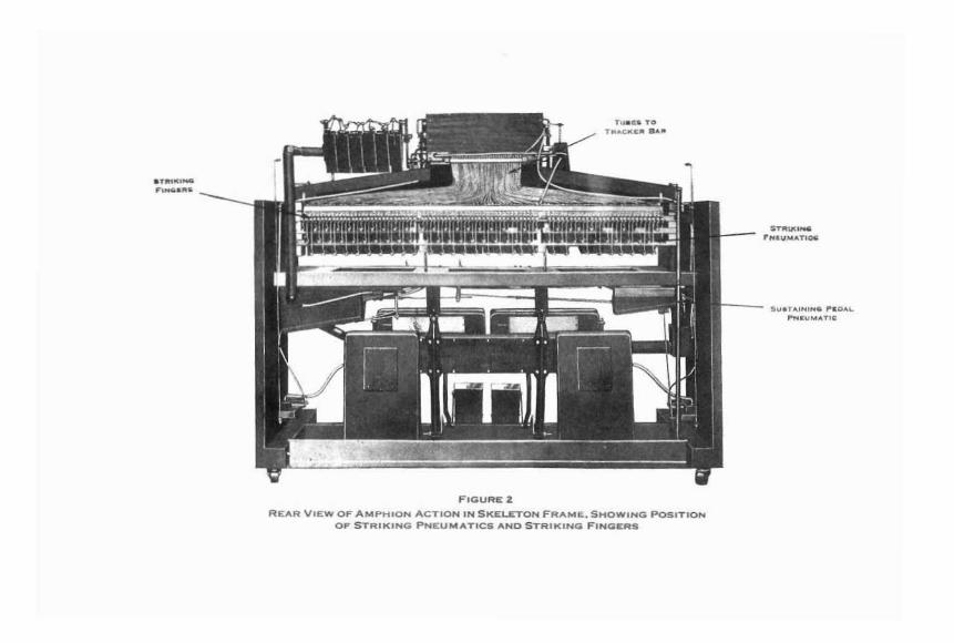
F IG URE: II
G ATE SOX
The gate box, which serves to interru pt the top action supply andprevent the playing of notes during reroll. is another independent un it .
It is simple in structure . cons ist ing onl y of the tube box and diaphracrn toad. which may be ta ken apart bv removing four screws
CO C ~'ON ~o O '".. .. uO....GO~E ~ V.~~E " LOCI< ""L""SLOG"
eo c"O ,O .. ~ O ., .........~ ' ~ "'.,..
''' L~ .
F IG URE 1 2
V E N T BLOCI<
ThIS part or the action is whac is known as a primary or relayvalve . serving to operate the cu t-o ft" diaphragm of the gate box and thereroll va lve of the covemor .
The diaphragr; peeker of the H:1t block assembly is connected inthe installa tion to a port in the transmission frame, which is closed whenthe transmiss ion is set in the "plev" posi ticv- ar-d open when the transmission is in the reroll position . During .oil the vent block valve islifted by its dtaphrecn an d in turn this" .ve admits atmosphere to thegate box and gOHr:10r -c-oll va lve d iar -agms. Thus the to p action iscut o lT from it s supp ly l:y the gete : JX. and the reroll valve of thego vernor prov ides a c.rece passage icr air from the air motor to bellows.around the governing valve thus inc' '~ s ing tho: speed of reroll.
The vent block is of simple an .... sturdy construction. Its val ..-e isfully protected . T he valve seats are of th , sam e moul ded compositionas is used in the unit valves . It ma y be taken apa rt without d ifficultyif necessary
21

\
R<s<~vO' ~
0" "oo. u u "
HA ... .. . .. R AOl.....' ,..AT'C S,, ~ ~••
FI G URE 13
BELLOWS
THE BELLOWS
Next to th e top action. the BeIlO\\"S or power p lant of the player isthe most important element of the mechanism
ln this bellows we have a most perfectly balanced uni t , exactlysuited in capacity to the needs of the action, and eas ily adjustable as topedal pressure and speed of pump ing to the desires of the operato r. Thebellows cast ings or supports are of cast iron sufficient ly heavy to withstand all stresses of operation. The same is t rue of the feeder castings.The design is such as to Involve th e least possib le number of mechan icaljo ints and moving parts between pedals and feeder pneumat ics.
Ample reservoir or equalizer capacity is prov ided and d ist ributedwith respect to r re..-<-sure to smooth out in a perfect manner the intermitten t act ion a the feeders.
The accent valve equ ipment of the bellows reacts with utmostprec ision and speed to the slightest accenting foot st roke, mak ing itunnecessary to anticipate the arrival at the t racker bar of notes to beaccented , and after accents have been produced there is no carry-everor sustained high intensity effect .

Su--o" T,,,,,..
F IG URE 1 4
S U ST... . NI N G P EO... L. PNEU M ...T . C
THE SLSTAI:" I:"G PEDAL P:"EL\ g T IC
In the sustaining pedal pneumat ic assembly the unit valvesyste m is employed as well as elsewhere in the action.
T wo valves ar e provided for the operation of this pneumaticon account of its see and the necessity of rapid operationOne of these valves is constructed with "e vent and the otheris not As the diaphragms of both va lves are connectedtogether, the single vent serves both of them.
ln the installa tion the valves are connected to the pedalswitch and to a finger bu t ton in the kevbed. so that thepneumatic is ope rated either from the note sheet or from thekeybed . or both , at the will of the operator
!J

FIGURE 15
R A I l.. L IFTI N G PNEUMATI C S
RAIL L1FTI:-':G P:-':El;,lHICS
Here again rhe u::it valve construction is seen.
In the case of rail lifting pneumatics. as contrasted with thesustain ing pedal pneumatic. only one unit valve is used onaccount of the smaller si:e of the pneumatic.
This valve is held in place aga inst the valve block by twostuds and nuts , and a specia l spring

How to keep anAMPHION PLAYERACTION in perfectWorkinQ Order

EVE RY mechanism, regardless of its kind or function, requires reasonablemechanical care and attention if it is to yield good mechanical service.The piano player action constitutes no exception to this rule. However,
in the Amphion Accessible Action the difficulties of upkeep are minimized atall points by the features of accessibility and simplicity outlined in the preceding section.
There are only two details in the way of routine upkeep that are of suchimportance as to require periodical attention on the part of the owner, butthese are really important and should be attended to regularly. These will beoutlined first, followed by more technical information intended primarily forthe tuner and repair man, but useful as well to the owner.
The (\"-0 items referred to are pumping out the tracker bar and lubrication.
THE TRACKER PUMPEvery owner of a player piano should have a good tracker bar pump
and should use it regularly.As the music roll is drawn across the tracker bar it is subjected to a
considerable abrasive or scraping action, which loosens small particles of fibrefrom the paper _ These particles are forced into the tracker ports by the airthat enters the openings during the playing of the roll.'
The small particles of paper, as well as atmospheric dust, collect in thetubes leading from the bar and obstruct the flow of air from tracker ports tovalve diaphragms. Eventually, they may reach the diaphragm pockets andthen may obstruct the small openings or vents that serve to discharge the airunder the diaphragms at the conclusion of the valve's cycle of operation.
Sluggish valve operation and clogged vents may be prevented and moreextensive cleaning operations may be avoided by the regular use of the trackerpump, which is a simple, hand operated suction pump or vacuum cleaner witha rubber tip shaped to fit the tracker bar, and a screen that serves to catch thematerial withdrawn from tracker bar openings.
Use the tracker pump regularly, and the most common difficulty withplayer pianos, that of impaired valve function, will be avoided.
No set rule can be laid down as to how frequently the tracker should bepumped out. This will depend upon how much the player is used, how muchatmospheric dust is present, and the kind and age of the music rolls. Somemusic roll papers are more easily abraded than others. New rolls wlll alwaysdischarge more lint into the tracker than old ones.
The best guide in the use of the tracker pump is the amount of themareral withdrawn from the bar. If a large amount of material is withdrawn, use the tracker pump quite frequently; otherwise, less frequently.
LUBRICATIONFailure to lubricate moving parts causes premature and unnecessary
wear, with its resultant development of looseness and noise.Points that should receive periodical lubrication are the:TRANSMISSION: Use light non-gumming oil on four shaft bearings, sliding
clutches, and gears. Also oil sparingly the surface of the rerol! valve at thebottom of the frame. Use vaseline on the chains and sprockets.
TAKE-UP SPOOL BEARI:---:G: Apply a few drops of light oil to the spindleat the left hand end of the take up spool, then rotate and move this spindlelengthwise in its bearing to distribute the oil.
26

MUSIC ROLL: Use light oil on the right and left hand music roll spindles.applying and distributing the oil as described above. '
PLUNGER BEARING TIP: Apply a few drops of oil to the rotating tip ofthe music spool plunger bearing at the left hand end of the music roll, turningthe tip to work the oil iota the joint.
BELLOWS PEDALS: Oil the bearing at the lower end of the pedal aboutwhich the pedal moves. At the upper end of the pedal oil the pedal linkconnection. Also oil the pin joint at the lower end of the pedal link where itis attached to the bellows feeder iron.
No other routine lubrication is required about the entire player. Thatoutlined above is important and should be looked after with the same regularity as is the periodical lubrication of an automobile. Thus squeaks,rattles, and premature wear may be avoided.
Excess oil applied at the various points should be wiped off to avoid itsspreading over adjacent surfaces.
VALVE FUNCTIONINGPerfect valve functioning is the first essential of good operating condi
tions in the player action.Practically every common valve trouble may be forestalled by frequent
and proper applications of the tracker pump.If tubes between tracker bar and unit valves should become obstructed
they may be disconnected at the unit valves and cleared by blowing into them.If vents become clogged, the valves are instantly removable, and the
vents may be cleaned with a pin.A clogged vent is indicated when a note speaks in response to opening its
tracker port but the valve does not close and allow the hammer to drop backfrom the string promptly after the tracker port is closed.
When valves are removed from decks for any purpose it is well to blowthem out to remove any accumulated dust. They should be assembled againto the same points from which they came. The packing between valves anddecks is somewhat compressible and develops imprints of the deck ports,therefore greater tightness of joints between unit valves and decks is maintained by returning the valves to their original positions.
Each action as manufactured is equipped with a number of spare unitvalves, attached to the decks in places where there are no striking pneumatics.Thus, trouble with any valve that is not readily corrected may be overcome bythe substitution of one of the extra units.
AUTOMATIC TRACKINGThe correct registration of tracker ports with their corresponding per
forations of the music roll is another detail essential to the perfect operation ofthe player.
The Amphion automatic tracking apparatus shifts the music roll and thusmoves the sheet longitudinally across the tracker bar instead of shifting thebar itself as is frequently done.
Referring to Figure 7 the roll adjusting pneumatic is seen at the left of thespool box. This is a double pneumatic with a movable center board attachedto the roll adjuster rod. Each side or section of this pneumatic is connectedthrough small internal orifices to a single supply tube, which is connected toone of the decks of the action.
Also each side of the pneumatic is connected to one of the roll adjustervalves, which are mounted above the tracker bar near its ends with their
27

wires overhanging the bar on the right and left edges of the music sheet. Thesevalves are normally closed when the sheet is in proper position. Under suchconditions both sides of the double pneumatic are subjected to the same tension, which holds its center board in a fixed position and centralizes the sheetover the bar.
With the sheet in motion, a movement of it lengthwise of the bar causesthe edge of the sheet to make contact with the valve wire toward which themotion occurs. This opens the valve and allows air to enter that side of thedouble pneumatic to which the valve is connected, rendering that side of thepneumatic inoperative. The opposite side of the pneumatic is thus allowed tocollapse. This moves the music roll back into proper position over the bar. Ifthe automatic tracking apparatus fails to function properly, the cause willusually be found to be a leak in the rubber cloth cover of the pneumatic or inits valve or supply connections.
Occasionally it may be necessary to adjust the roll adjuster valves, andthis is readily done by simply bending the valve wires with the fingers. Whenthe sheet is in proper registry with the bar the weights at the rear of thesevalve wires should seal the tubes with which they make contact and the wiresshould just clear the edges of the sheet.
BRAKE DRUM AND MUSIC ROLL BRAKEThese parts (illustrated in Fig. 8) and their adjustment, require special
mention only because they constitute an important factor in connection withmaintaining proper tempo, or speed of travel, of the music sheet.
The brake drum is integral with the sprocket that drives the upper righthand spindle of the music roll during the reroll of the sheet. During the rerolloperation the brake stick is lifted away from the drum by the transmissionlever and the brake has no function to perform. However, with the sheettraveling forward over the tracker bar, the brake stick is in contact with thedrum, serving to check the rotation of the music roll and subjecting the paperto tension which maintains proper contact between paper and tracker bar.
The contact pressure between the brake stick and the brake drum isadjustable by means of a flat brake stick spring, the free end of which restson the. brake adjuster. This is an eccentric knob mounted on the spool boxand supporting the free end of the spring. Rotation of this knob to create agreater spring pressure increases the tension on the music sheet. Rotation ofit in the opposite direction decreases the tension of the sheet.
The music sheet tension should be just great enough to keep the paperfrom vibrating between the music spool and tracker bar, thus preventing thepaper from rolling up on the take-up spool too loosely. Too great a tension onthe sheet may cause tempo irregularities. Too little tension on the sheetallows slack to form in the paper as it is wound about the take-up spool. Thisslack may be taken up at intervals during the playing of a roll by the continued rotation of the take-up spool while the travel of the sheet over the bardecreases in speed or stops altogether. It is therefore important to check themusic sheet tension and to adjust the music roll brake, if necessary, beforeproceeding with any other tempo adjustments as described hereafter.
CARE OF THE AIR MOTORThe main point to be observed in connection with the care of the air
motor is that of following the instruction card attached to it. Neither oil norgrease should ever be applied to the air motor slide valves. I f these parts
28

require lubrication finely powdered dry graphite is the only proper lubricantto use.
The position of all three of the slide valves is carefully adjusted at thefactory; but if adjustments in valve setting are necessary to smooth out therotation of the motor crank shaft, such adjustments are readily made byslightly bending the valve connecting wires.
In case the slide valves and their plates become covered with sufficientatmospheric dust to interfere with their free operation, and require thoroughcleaning and relubrication, the proper procedure is as follows:
First, remove the valves from the motor and clean the motor valve seatsby wiping them off with gasoline. Next, surface the contact faces of the valvesby rubbing them lengthwise on very fine sand paper held on a perfectly flatsurface. Then rub the sanded surfaces of the valves thoroughly with finelypowdered dry graphite working the material into the pores of the wood.Finally, replace the valves on the motor in their original positions so as tomaintain the original adjustments and to avoid readjusting the valve setting.
There is no objection to the use of a little oil mixed with graphite on thebushings of the air motor wires where they are attached to the crankshaft,if lubrication at these points is necessary to avoid any squeaks that maydevelop. The end bearings of the crankshaft may be similarly lubricated, ifnecessary. However, these bushed bearings should preferably be lubricated,when they require it, with dry graphite only.
AIR MOTOR GOVERNORIn detail the construction and functioning of this part illustrated by
Figure 10 is as follows'The governor is connected in the tubing line leading from the bellows to
the air motor for the two-fold purpose of controlling the tempo or rate oftravel of the music sheet over the tracker bar and of maintaining a constantrate of travel for a given tempo setting, irrespective of the bellows tension.
Air from the motor enters the upper chamber of the governor and flowsthrough the open section of the tempo slot into the governing pneumatic. Theextent to which the tempo slot is open in connection with the governor springtension determines the rate of air influx, and thus the rate of rotation of themotor and the speed of the paper over the tracker bar. The tempo slot opening is determined by the position of the tempo slide valve, the wire of which isconnected in the installation to the tempo lever in the key bed and the tempoindicator pointer in the spool box.
From the governing pneumatic the air f10\VS through the governing valveand thence from the governor to the bellows through the connecting tube.
The governing valve operated through its lever by the movable board ofthe governing pneumatic serves to maintain constant tension within thepneumatic in the following manner:
Under operating conditions air pressure within the governor is less thanthe external atmospheric pressure and the excess external pressure tends tocollapse the governor pneumatic, thus closing the governor valve. Against thisaction is the resistance of the governing pneumatic spring, the tension of whichis adjustable by the nut at its end. Consequently, with a given adjustment ofthis spring, a balanced condition prevails between the pressure tending tocollapse the pneumatic and close the valve and the'sprtng tension opposing thisaction. This creates a constant tension in the governor applied to the temposlot opening for any given bellows tension.
29

However, a constant bellows tension does not prevail in the Foot Pumpaction, and while other governors compensate imperfectly, or not at all, forvariations in bellows tension, the Amphion governor provides perfect compensation for such changes, maintaining constant tempo under all conditionsof pumping.
This compensation is accomplished by means of the small auxiliary pneumatic attached to the governor, connected by a supply tube to the bellowsside of the governing valve. The interior of this pneumatic is therefore alwayssubjected to bellows tension. Consequently a greater or less force, accordingto fluctuations in bellows tension, tends to collapse this compensating pneumatte. This force is transmitted to the movable board of the governingpneumatic by means of the post and compensating spring attached to the tipof the compensating pneumatic. Thus a compensating force is appliedthrough the movable board to the governing valve according to the bellowstension that may prevail. This serves to regulate exactly the opening of thisvalve according to any bellows tension that may prevail, the valve being morenearly closed under high bellows tension conditions and opened further underlow bellows tension condition.
To expedite reroll at any position of the tempo setting, a by-pass valve ispresent in the governor which is lifted during reroll by its diaphragm to provide a direct path of communication for the air from the motor to the bellowsaround the tempo slot and governor valve. The by-pass or reroll valvediaphragm of the governor is inflated by atmosphere admitted to it throughthe vent block valve when this valve is operated by the opening of the transmission port, when the transmission lever is in the reroll position.
The compensating pneumatic of the governor is carefully adjusted to perform its function properly at the factory and rarely if ever needs attention,but should occasion require, this element may be adjusted as follows:
If the rate of note sheet travel tends to increase under heavy pumpingand to decrease under light pumping the effective length of the post betweencompensating pneumatic tip and compensating spring should be increased byadding one or more washers of felt or cardboard at the end of the post. If thereverse occurs decrease the effective length of the spring post by removingpunchings.
TEMPO REGULATOR AND GOVERNOR ADJUSTMENTSeveral conditions are involved in maintaining correct tempo regulation
and since this is such an important factor in the quality of musical renditionthese will be outlined at some length.
First of all, it is important to have all moving parts of the transmission,air motor, etc., in good mechanical condition. Therefore, before any governoradjustments or other tempo adjustments are made, these details should haveattention.
See that the music roll bearings, the take up spool bearings, and the transmission are clean, properly lubricated, and in general, in good running order.For instructions concerning the lubrication of these parts see the previoussection on Lubrication.
Next, see that the music spool brake is properly adjusted to apply theproper amount of tension to the music sheet. Make necessary adjustmentsaccording to instructions contained in the section on this subject.
Following this, see that the air motor is operating properly. If it is not,follow the instructions given on the care of the air motor.
JO
Also see that the transmission and air motor chains are lubricated and areproperly tensioned, adjusting the chain idlers, if necessary, to bring aboutproper conditions.
It will be found that many tempo irregularities, when encountered, maybe traced to improper conditions among any or all of the above mentionedparts. Setting all of them in good order frequently obviates the necessity oCmaking governor adjustments.
Proceeding now to the governor, the mechanical connections from thetempo slide valve wire to the tempo lever in the key bed and to the tempoindicator pointer should be checked and adjusted if necessary. With thetempo lever at its extreme left position the tempo indicator pointer shouldstand at "0" or a little below this point on the scale. With this condition prevailing the air motor should not run but should just start when the tempopointer is shifted to the neighborhood of 10 on the scale.
The levers at the rear of the tempo lever rod should swing an equal distance to the right and left of a vertical position when tempo pointer is movedfrom 0 to 120on the tempo scale.
Adjustment to bring about these conditions may be made, if necessary,by regulating the lengths of wires that connect the tempo indicator to its leveron the tempo rod under the key bed, and by adjusting the nuts on the temposlide valve wire of the governor.
After all mechanical conditions are as they should be according to theabove, set the tempo indicator at 70 and time the rate of music sheet travelover the tracker bar by using a roll with two marks on it 351ft. apart. Attempo 70 the roll should move from one mark to the next in half a minute, orat the rate of 7 ft. per minute. If the movement is too slow, increase the tension on the governing pneumatic spring by adjusting the nuts on the springwire toward the top board of the governor. If the movement is too rapidadjust the spring tension in the reverse direction.
In case tempo irregularities prevail in connection with variable bellowstensions, adjust the length of the compensating pneumatic spring post of thegovernor according to instructions previously given.
BELLOWS CARE AND ADJUSTMENTSLubrication of pedal bearings and pedal connecting links constitute the
only routine care required by the bellows. For instructions concerning thissee the previous section on' 'Lubrication.'
The pumping characteristics of the bellows may be changed within widelimits to suit the pleasure of the individual operator as follows:
Two holes are provided in each pedal for the connection of the upperend of the pedal link. The pedal link Is assembled to the pedal at one of thesetwo points by means of a screw held in place by a set screw through the backsurface of the pedal. which must be loosened or backed off, before the point ofattachment of the pedal link to the pedal can be changed. Two holes areprovided in the lower end of the pedal link for its attachment to the bellowsfeeder iron. Also two holes are provided in the bellows feeder iron for theattachment of thelink.
The condition which yields the easiest pumping, as measured by the lightest pressure or resistance under foot, is that which provides the greatest leverage between the pedal and the movable board of the bellows feeder. Thiscondition prevails when the pedal link is attached to the lower hole of the pedal
n

and attached to the lower hole of the bellows feeder casting, making use of thesecond hole in the end of the pedal link for the latter connection.
Although the above described connection between the pedal and thebellows feeder iron provides the least pedal resistance under foot, it alsonecessarily involves a greater rapidity of pedal strokes. Therefore, while oneindividual might consider this to be the easiest or lightest pumping condition,another might prefer heavier pedal pressure under foot with less speed ofpedaling.
It is because of the different tastes of individuals in this respect that theAmphion Action bellows is made with the wide range of adjustments itpossesses to vary the pumping characteristics. The mechanical condition forheaviest pressure under foot and lowest speed of pumping is the reverse ofthat outlined above, namely; the adjustment of the pedal link to the upper holeof the pedal and to the upper hole of the feeder casting, employing for thelatter connection the end hole of the lime
Various combinations between these two extremes of mechanical connections are obviously possible, and the combination best suited to the needs ofthe individual owner may be selected.
Adjustment of the accent valve of the bellows is rarely, if ever, necessary;but this member of the apparatus is readily accessible if adjustments arerequired. The accent valve is situated in the bass or right hand reservoirpneumatic of the beilows. The removal of the small panel from the back ofthis pneumatic exposes the valve, which is a simple open-end pneumatic,normally held open by means of a spring in its hinge end to allow the free passage of air between the wind chest of the bellows and the reservoir pneumatic.
A sudden foot stroke, either heavy or light, applied to either pedalinstantly closes the accent valve or pneumatic, thus interrupting the means ofcorrununication between the bellows wind chest and the bass reservoir pneumatic. Following such a foot stroke the accent valve springs open and opensthe connection between the two parts. If accents are too sharp the tension ofthe spring at the hinge end of the valve or pneumatic should be increased. Ifaccents are not sufficiently sharp this spring tension should be decreased.
The treble reservoir pneumatic of the bellows is not provided with anaccent valve. Thus it is always in communication with the wind chest of thebellows. The capacity of this pneumatic and the arrangement of its internalsprings is such as to cause it to function as an equalizer for the intermittentstrokes of the pedal and to provide an ever present cushion for pedal strokesthroughout all ranges of bellows tension.
GENERALSince no manual of Instructions on the care and upkeep of the player
action can be so complete as to cover every situation in the way of improperfunctioning that may arise, it is the policy of the manufacturer of this actionto invite correspondence on unusual difficulties and their treatment.
Anyone who encounters difficulty with an Amphion Accessible Actionend cannot correct it with the aid of the foregoing information should communicate at once with the manufacturer, sending a complete descriptionof the difficulty with information as to what, if any, steps may have been takento overcome it.
n

THE RECORDO ROLL EXPRESSION ACTION
I N addition to being made as a straight foot pump playerthe Amphion Accessible Action is also constructed as anautomatic expression player for the Recorda Music Roll.
In this form the action possesses every feature of distinction and accessibility of the regular Arnphion Action,because in its principal parts it is identical with the actiondescribed on the preceding pages. In fact, the Recordo RollExpression Action by the shifting of a small lever in thespool box may be made to operate exactly as the regular footpump action, with any type of music roll.
The expression apparatus of the Recorda Action issimple in structure and possesses every feature of completeaccessibility and ease of maintenance characteristic of theArnphion Action in general.
At the same time the expression apparatus is constructed in principle along lines that yield complete controlof expression from the Recorda Music Roll, and insure theinterpretation of the music exactly according to the cuttingof the roil.
The details of construction of the Recordo Actionexpression apparatus are explained in a supplementarybooklet.