Ford LSG to LRG Engine Conversion Supplement (PN 35023) - Genie
48
Technical Publications First Edition, Third Printing Part No. 35023 Service Manual Supplement ® S-40 Z-45/22 S-80 & 85 For the following products: Z-60/34
Transcript of Ford LSG to LRG Engine Conversion Supplement (PN 35023) - Genie

TechnicalPublications
First Edition, Third PrintingPart No. 35023
ServiceManual
Supplement®
S-40
Z-45/22
S-80 & 85
For the following products:
Z-60/34

Genie Supplement Part No. 35023
First Edition
ii
®
Copyright © 1995 by Genie Industries
First Edition: First Printing, February 1995Second Printing, March 1995Third Printing, June 1995
Genie® is a registered trademarkof Genie Industries. Registered 2009987
Patents pending
Printed on recycled paper
Printed in U.S.A.
Genie Industries has endeavored to deliver thehighest degree of accuracy possible. However,continuous improvement of our products is aGenie policy. Therefore product specifications aresubject to change without notice.
Readers are encouraged to notify Genie of errorsand send in suggestions for improvement. Allcommunications will be carefully considered forfuture printings of this and other manuals. Pleasewrite or fax to the Technical Publications team:
Genie IndustriesPO Box 69Redmond, WA 98073-6900, USAFax Number: (206) 556-8528.
If you have any questions, call Genie Industries.
Genie North AmericaTelephone (206) 881-1800Toll Free in U.S.A. 800 536-1800Toll Free in Canada 800 426-8089Fax (206) 883-3475
Genie EuropeTelephone (44) 01636-605030Fax (44) 01636-611090
Part No. 35023 Genie Supplement
First Edition
How To Use This Supplement
This supplement is an addition to the servicemanuals listed below. The serial numbers listedbelow mark the first affected machine . Only thefollowing changes are documented in thissupplement:
Replacement of the Ford LSG-423 enginewith the Ford LRG-423 engine
If you have any questions about what thissupplements covers or how it fits in to yourexisting documentation, please call the GenieIndustries Service Department.
Service Manual
There are four sections to the service manualsupplement.
The Specifications section contains only thespecifications for Ford LRG-423 Engine.
The maintenance section contains only thosemaintenance procedures that are different for theFord LRG engine. Please note the procedurenumber for your machine, indentified at thebeginning of each procedure in this supplement.
The schematic section contains complete, updatedelectrical schematics for the Gasoline/LPGmachines. The schematics are arranged byproduct.
The repair section contains the complete FordLRG engine section. Please note the sectionnumber for your machine.
Service Manuals:Product Part NumberS-40 32222S-80 & S-85 34032Z-45/22 32960Z-60/34 30105
iii
Serial Number Breaks:Product Machines afterS-40 271S-80 & S-85 132Z-45/22 2134Z-60/34 481

Genie Supplement Part No. 35023
First Edition
Table of Contents
Section One Specifications
Ford LRG-423 Engine ................................................................................................................................ 1
Section Two Scheduled Maintenance Procedures
B-1 Check the Engine Belt(s) ............................................................................................... 2
B-2 Check and Adjust the Engine Idle Mixture - Gasoline/LPG Models ............................... 2
B-3 Check and Adjust the Engine RPM ............................................................................... 2
C-1 Replace the Gasoline Fuel Filter - Gasoline/LPG Models ............................................. 4
C-2 Replace the PCV Valve - Gasoline/LPG Models ........................................................... 5
C-3 Replace the Spark Plugs - Gasoline/LPG Models ......................................................... 6
C-4 Check and Adjust the Air/LPG Mixture - Gasoline/LPG Models .................................... 6
C-5 Check and Adjust the Ignition Timing - Gasoline/LPG Models ...................................... 8
D-1 Change or Recondition the Engine Coolant - Gasoline/LPG Models............................. 8
D-2 Change the Fuel Lines .................................................................................................. 9
D-3 Check the Engine Valve Clearance - Gasoline/LPG Models ....................................... 10
D-4 Check the Engine Cylinder Compression - Gasoline/LPG Models .............................. 10
D-5 Clean the PCV Hoses and Fittings - Gasoline/LPG Models ........................................ 11
D-6 Replace the Timing Belt - Gasoline/LPG Models ........................................................ 12
Section Three S-40 Electrical Schematics
Electrical Schematic - Gasoline/LPG Models .............................................................. 13
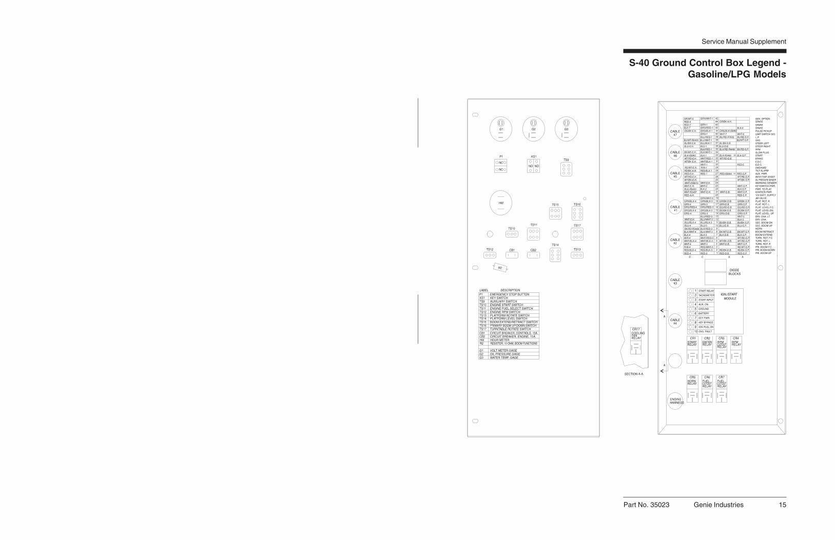
Ground Control Box Legend - Gasoline/LPG Models .................................................. 15
Relay Panel Legend - Gasoline/LPG Models .............................................................. 16
Platform Control Box Legend - Gasoline/LPG Models ................................................ 17
S-80/85 Electrical Schematics
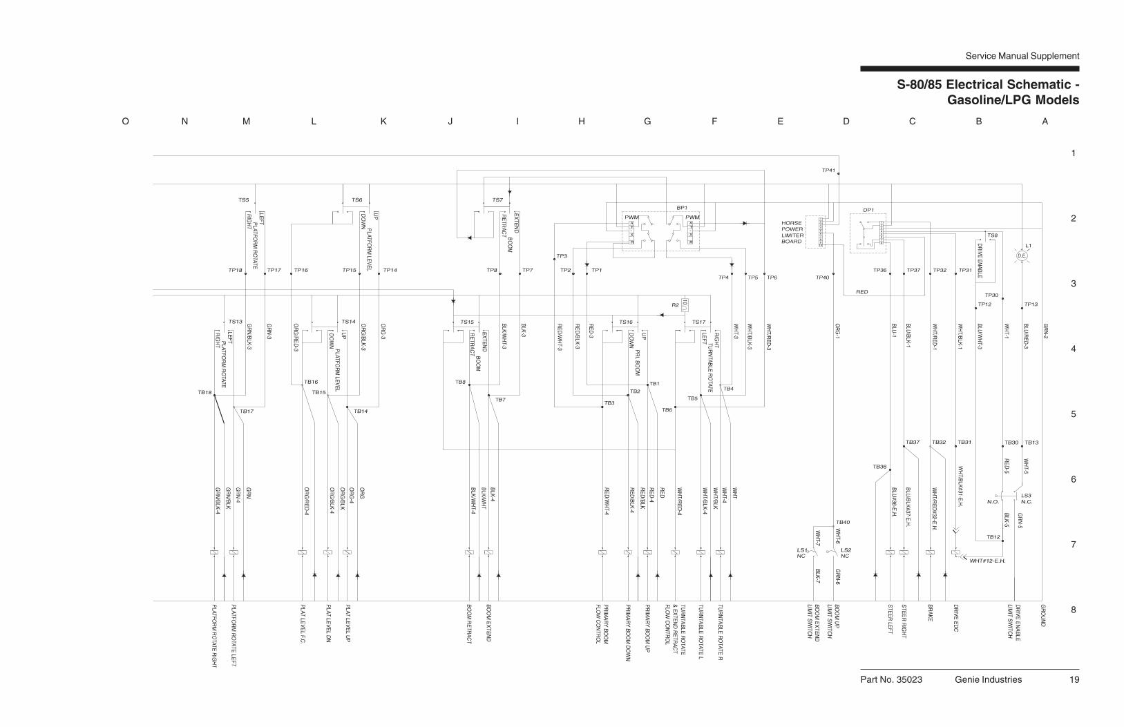
Electrical Schematic - Gasoline/LPG Models .............................................................. 18
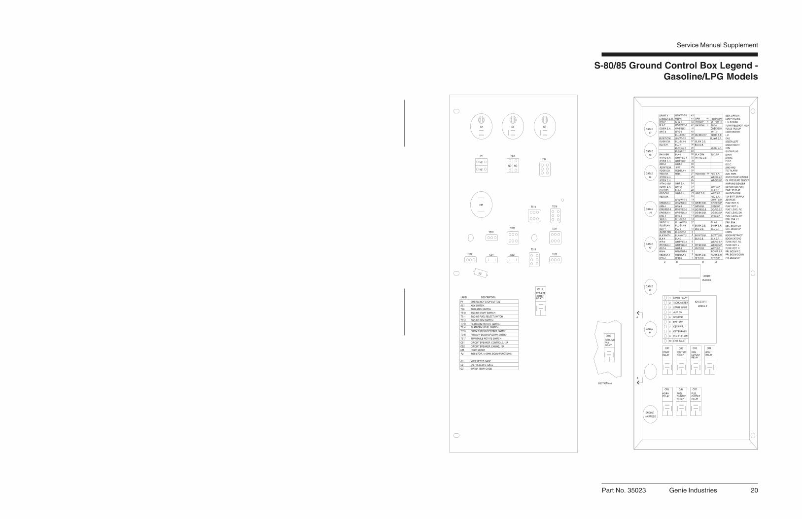
Ground Control Box Legend - Gasoline/LPG Models .................................................. 20
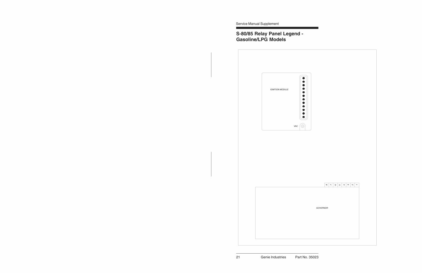
Relay Panel Legend - Gasoline/LPG Models .............................................................. 21
Platform Control Box Legend - Gasoline/LPG Models ................................................ 22
Z-45/22 Electrical Schematics
Electrical Schematic - Gasoline/LPG Models .............................................................. 23
Ground Control Box Legend - Gasoline/LPG Models .................................................. 25
Relay Panel Legend - Gasoline/LPG Models .............................................................. 26
Platform Control Box Legend - Gasoline/LPG Models ................................................ 27
iv

Part No. 35023 Genie Supplement
First Edition
Section Three, continued
Z-60/34 Electrical Schematics
Electrical Schematic - Gasoline/LPG Models .............................................................. 28
Ground Control Box Legend - Gasoline/LPG Models .................................................. 30
Relay Panel Legend - Gasoline/LPG Models .............................................................. 31
Platform Control Box Legend - Gasoline/LPG Models ................................................ 32
Section Four Repair Procedures7-1 Governor Actuator ............................................................................................. 33
7-2 Choke Adjustments ............................................................................................ 34
7-3 Timing Adjustment ............................................................................................. 35
7-4 Carburetor Adjustment ....................................................................................... 35
7-5 RPM Adjustment ................................................................................................ 35
7-6 Flex Plate ........................................................................................................... 35
7-7 Water Temperature and Oil Pressure Gauges................................................... 36
7-8 Vacuum Switch .................................................................................................. 36
v

Genie Supplement Part No. 35023
First Edition
Part No. 35023 Genie Industries 1
First Edition Service Manual Supplement
Specifications
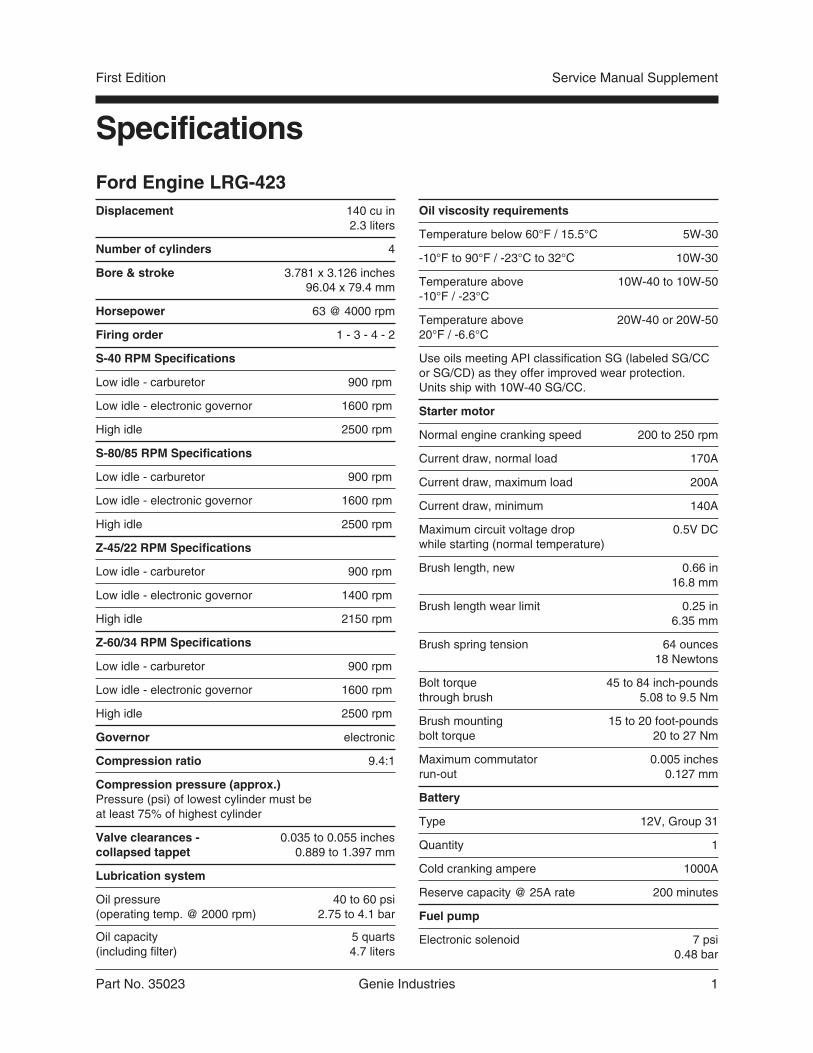
Ford Engine LRG-423Displacement 140 cu in
2.3 liters
Number of cylinders 4
Bore & stroke 3.781 x 3.126 inches96.04 x 79.4 mm
Horsepower 63 @ 4000 rpm
Firing order 1 - 3 - 4 - 2
S-40 RPM Specifications
Low idle - carburetor 900 rpm
Low idle - electronic governor 1600 rpm
High idle 2500 rpm
S-80/85 RPM Specifications
Low idle - carburetor 900 rpm
Low idle - electronic governor 1600 rpm
High idle 2500 rpm
Z-45/22 RPM Specifications
Low idle - carburetor 900 rpm
Low idle - electronic governor 1400 rpm
High idle 2150 rpm
Z-60/34 RPM Specifications
Low idle - carburetor 900 rpm
Low idle - electronic governor 1600 rpm
High idle 2500 rpm
Governor electronic
Compression ratio 9.4:1
Compression pressure (approx.)Pressure (psi) of lowest cylinder must beat least 75% of highest cylinder
Valve clearances - 0.035 to 0.055 inchescollapsed tappet 0.889 to 1.397 mm
Lubrication system
Oil pressure 40 to 60 psi(operating temp. @ 2000 rpm) 2.75 to 4.1 bar
Oil capacity 5 quarts(including filter) 4.7 liters
Oil viscosity requirements
Temperature below 60°F / 15.5°C 5W-30
-10°F to 90°F / -23°C to 32°C 10W-30
Temperature above 10W-40 to 10W-50-10°F / -23°C
Temperature above 20W-40 or 20W-5020°F / -6.6°C
Use oils meeting API classification SG (labeled SG/CCor SG/CD) as they offer improved wear protection.Units ship with 10W-40 SG/CC.
Starter motor
Normal engine cranking speed 200 to 250 rpm
Current draw, normal load 170A
Current draw, maximum load 200A
Current draw, minimum 140A
Maximum circuit voltage drop 0.5V DCwhile starting (normal temperature)
Brush length, new 0.66 in16.8 mm
Brush length wear limit 0.25 in6.35 mm
Brush spring tension 64 ounces18 Newtons
Bolt torque 45 to 84 inch-poundsthrough brush 5.08 to 9.5 Nm
Brush mounting 15 to 20 foot-poundsbolt torque 20 to 27 Nm
Maximum commutator 0.005 inchesrun-out 0.127 mm
Battery
Type 12V, Group 31
Quantity 1
Cold cranking ampere 1000A
Reserve capacity @ 25A rate 200 minutes
Fuel pump
Electronic solenoid 7 psi0.48 bar

2 Genie Industries Part No. 35023
Service Manual Supplement First Edition
B-1Check the Engine Belt(s)
Genie S-40 models: Thisprocedure replaces B-1.
Genie S-80/85 models: Thisprocedure replaces B-1.
Genie Z-45/22 models: Thisprocedure replaces B-1.
Genie Z-60/34 models: Thisprocedure replaces B-1.
Maintaining the engine belt(s) is essential to goodengine performance and service life. The machinewill not operate properly with a loose or defectivebelt and continued use may cause componentdamage.
Do not inspect while the engineis running. Remove the key tosecure from operation.
Beware of hot enginecomponents. Contact with hotengine components may causesevere burns.
1 Inspect the engine belt for:
· cracking
· glazing
· separation
· breaks
Ford LRG-423 engines areequipped with a serpentine beltand incorporate a self adjustingpulley tensioner. No adjustment isrequired.
Scheduled Maintenance Procedures
B-2Check and Adjust the Engine IdleMixture - Gasoline/LPG Models
Genie S-40 models: Thisprocedure replaces B-11.
Genie S-80/85 models: Thisprocedure replaces B-11.
Genie Z-45/22 models: Thisprocedure replaces B-11.
Genie Z-60/34 models: Thisprocedure replaces B-11.
Complete information to perform this procedure isavailable in the Ford LRG-423 2.3 Liter IndustrialEngine Service Manual (Ford number: PPD-194-287). Genie part number 33907.
B-3Check and Adjust theEngine RPM
Genie S-40 models: Thisprocedure replaces B-12.
Genie S-80/85 models: Thisprocedure replaces B-12.
Genie Z-45/22 models: Thisprocedure replaces B-12.
Genie Z-60/34 models: Thisprocedure replaces B-12.
Maintaining the engine rpm at the proper settingfor both low and high idle is essential to goodengine performance and service life. The machinewill not operate properly if the rpm is incorrect andcontinued use may cause component damage.
Perform this procedure in gasolinemode with the engine at normaloperating temperature.
1 Disconnect the blue/black wire from thegovernor actuator.

Part No. 35023 Genie Industries 3
First Edition Service Manual Supplement
SCHEDULED MAINTENANCE PROCEDURES
2 Connect an rpm gauge to the engine, then startthe engine from the ground controls.
Result: Refer to the RPM Specification chart forthe correct rpm setting.
Skip to step 4 if the low idle rpm is correct.
3 Turn the idle adjustment screw on thecarburetor clockwise to increase rpm orcounterclockwise to decrease rpm.
Gasoline/LPG low idle adjustmenta carburetorb adjustment screw
4 Turn the engine off and reconnect theblue/black wire to the governor actuator.
5 Start the engine from the ground controls.
Result: Refer to the RPM Specification chart forthe correct rpm setting.
6 Move the engine idle control switch to high idle(rabbit symbol) from the ground controls.
Result: Refer to the RPM Specification chart forthe correct rpm setting.
7 Turn the engine off.
If low and high idle rpm’s are correct,disregard adjustment steps 8 and 9.
8 Remove the mounting fasteners from theelectronic governor located on the engineside bulkhead, then remove the back panelfrom the governor.
b
a
9 Restart the engine, turn the low or high speedset screw clockwise to increase the rpm orcounterclockwise to decrease the rpm.
Do not adjust any trimpot otherthan specified in this procedure.
Gasoline/LPG idle adjustmenta low idle adjustmentb high idle adjustment
10 Apply a drop of silicone to the top of the trimpotscrew. Apply a bead of silicone to the surfaceof the back panel prior to re-assembly.
11 Re-assemble the governor and recheck lowand high idle.
S-40 RPM Specifications
Low idle - carburetor 900 rpm
Low idle - electronic governor 1600 rpm
High idle 2500 rpm
S-80/85 RPM Specifications
Low idle - carburetor 900 rpm
Low idle - electronic governor 1600 rpm
High idle 2500 rpm
Z-45/22 RPM Specifications
Low idle - carburetor 900 rpm
Low idle - electronic governor 1400 rpm
High idle 2150 rpm
Z-60/34 RPM Specifications
Low idle - carburetor 900 rpm
Low idle - electronic governor 1600 rpm
High idle 2500 rpm
b
a
4 Genie Industries Part No. 35023
Service Manual Supplement First Edition
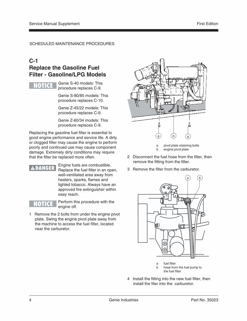
C-1Replace the Gasoline FuelFilter - Gasoline/LPG Models
Genie S-40 models: Thisprocedure replaces C-9.
Genie S-80/85 models: Thisprocedure replaces C-10.
Genie Z-45/22 models: Thisprocedure replaces C-9.
Genie Z-60/34 models: Thisprocedure replaces C-9.
Replacing the gasoline fuel filter is essential togood engine performance and service life. A dirtyor clogged filter may cause the engine to performpoorly and continued use may cause componentdamage. Extremely dirty conditions may requirethat the filter be replaced more often.
Engine fuels are combustible.Replace the fuel filter in an open,well-ventilated area away fromheaters, sparks, flames andlighted tobacco. Always have anapproved fire extinguisher withineasy reach.
Perform this procedure with theengine off.
1 Remove the 2 bolts from under the engine pivotplate. Swing the engine pivot plate away fromthe machine to access the fuel filter, locatednear the carburetor.
b aa
a pivot plate retaining boltsb engine pivot plate
2 Disconnect the fuel hose from the filter, thenremove the fitting from the filter.
3 Remove the filter from the carburetor.
a fuel filterb hose from the fuel pump to
the fuel filter
4 Install the fitting into the new fuel filter, theninstall the fiter into the carburetor.
a b
SCHEDULED MAINTENANCE PROCEDURES
Part No. 35023 Genie Industries 5
First Edition Service Manual Supplement
5 Connect the fuel hose to the filter.
6 Clean up any fuel that may have spilled duringthe installation procedure.
7 Start the machine from the ground controls,then inspect the fuel filter and hose for leaks.
If a fuel leak is discovered, keepany additional personnel fromentering the area and do notoperate the machine. Repairthe leak immediately.
8 Swing the engine pivot plate back to its originalposition and replace the two retaining bolts.
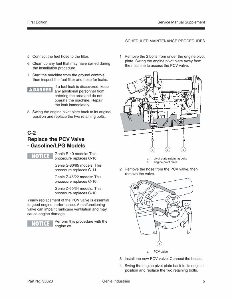
C-2Replace the PCV Valve- Gasoline/LPG Models
Genie S-40 models: Thisprocedure replaces C-10.
Genie S-80/85 models: Thisprocedure replaces C-11.
Genie Z-45/22 models: Thisprocedure replaces C-10.
Genie Z-60/34 models: Thisprocedure replaces C-10.
Yearly replacement of the PCV valve is essentialto good engine performance. A malfunctioningvalve can impair crankcase ventilation and maycause engine damage.
Perform this procedure with theengine off.
1 Remove the 2 bolts from under the engine pivotplate. Swing the engine pivot plate away fromthe machine to access the PCV valve.
a pivot plate retaining boltsb engine pivot plate
2 Remove the hose from the PCV valve, thenremove the valve.
a PCV valve
3 Install the new PCV valve. Connect the hoses.
4 Swing the engine pivot plate back to its originalposition and replace the two retaining bolts.
ba a
a
SCHEDULED MAINTENANCE PROCEDURES
6 Genie Industries Part No. 35023
Service Manual Supplement First Edition
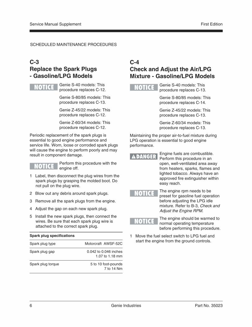
C-3Replace the Spark Plugs- Gasoline/LPG Models
Genie S-40 models: Thisprocedure replaces C-12.
Genie S-80/85 models: Thisprocedure replaces C-13.
Genie Z-45/22 models: Thisprocedure replaces C-12.
Genie Z-60/34 models: Thisprocedure replaces C-12.
Periodic replacement of the spark plugs isessential to good engine performance andservice life. Worn, loose or corroded spark plugswill cause the engine to perform poorly and mayresult in component damage.
Perform this procedure with theengine off.
1 Label, then disconnect the plug wires from thespark plugs by grasping the molded boot. Donot pull on the plug wire.
2 Blow out any debris around spark plugs.
3 Remove all the spark plugs from the engine.
4 Adjust the gap on each new spark plug.
5 Install the new spark plugs, then connect thewires. Be sure that each spark plug wire isattached to the correct spark plug.
Spark plug specifications
Spark plug type Motorcraft AWSF-52C
Spark plug gap 0.042 to 0.046 inches1.07 to 1.18 mm
Spark plug torque 5 to 10 foot-pounds7 to 14 Nm
SCHEDULED MAINTENANCE PROCEDURES
C-4Check and Adjust the Air/LPGMixture - Gasoline/LPG Models
Genie S-40 models: Thisprocedure replaces C-13.
Genie S-80/85 models: Thisprocedure replaces C-14.
Genie Z-45/22 models: Thisprocedure replaces C-13.
Genie Z-60/34 models: Thisprocedure replaces C-13.
Maintaining the proper air-to-fuel mixture duringLPG operation is essential to good engineperformance.
Engine fuels are combustible.Perform this procedure in anopen, well-ventilated area awayfrom heaters, sparks, flames andlighted tobacco. Always have anapproved fire extinguisher withineasy reach.
The engine rpm needs to bepreset for gasoline fuel operationbefore adjusting the LPG idlemixture. Refer to B-3, Check andAdjust the Engine RPM.
The engine should be warmed tonormal operating temperaturebefore performing this procedure.
1 Move the fuel select switch to LPG fuel andstart the engine from the ground controls.

Part No. 35023 Genie Industries 7
First Edition Service Manual Supplement
SCHEDULED MAINTENANCE PROCEDURES
2 Loosen the high idle mixture adjustmentlock nut.
a high idle mixtureadjustment screw
3 Load the system by pressing the boom retractswitch, then move the engine idle controlswitch to high idle (rabbit symbol).
4 Adjust the high idle adjustment screw to obtainan air-to-fuel mixture ratio of 13.0:1 to 13.2:1,using an exhaust gas analyzer.
Preliminary setting is 1/4 inch ofthreads showing. Measure fromtop of lock nut to top of adjustmentscrew.
If an exhaust gas analyzer is notavailable, adjust to obtain peak oroptimum rpm.
5 Hold the adjustment screw and tighten thelock nut.
a
6 Move the engine idle control switch to low idle(turtle symbol) and adjust the low idle screw toobtain an air-to-fuel mixture ratioof 13.0:1 to 13.2:1.
a low idle mixture adjustment screw
Preliminary setting: turn low idleadjustment screw clockwise all theway in. Turn low idle adjustmentscrew counterclockwise 2 3/4turns.
a

8 Genie Industries Part No. 35023
Service Manual Supplement First Edition
SCHEDULED MAINTENANCE PROCEDURES
C-5Check and Adjust the IgnitionTiming - Gasoline/LPG Models
Genie S-40 models: Thisprocedure replaces C-14.
Genie S-80/85 models: Thisprocedure replaces C-15.
Genie Z-45/22 models: Thisprocedure replaces C-14.
Genie Z-60/34 models: Thisprocedure replaces C-14.
Complete information to perform this procedure isavailable in the Ford LRG-423 2.3 Liter IndustrialEngine Service Manual (Ford number: PPD-194-287). Genie part number 33907.
D-1Change or Recondition theEngine Coolant- Gasoline/LPG Models
Genie S-40 models: Thisprocedure replaces D-2.
Genie S-80/85 models: Thisprocedure replaces D-2.
Genie Z-45/22 models: Thisprocedure replaces D-2.
Genie Z-60/34 models: Thisprocedure replaces D-2.
Replacing or reconditioning the engine coolant isessential to good engine performance and servicelife. Old or dirty coolant may cause the engine toperform poorly and continued use may causeengine damage. Extremely dirty conditions mayrequire coolant to be changed more frequently.
Beware of hot engine parts andcoolant. Contact with hot engineparts and/or coolant will causesevere burns.
Perform this procedure with theengine off and cooled.
1 Put on protective clothing and eye wear.
2 Disconnect the coolant return hose at theradiator and drain the coolant return tank.
3 Remove the radiator cap from the radiator.
4 Remove the 2 bolts from under the engine pivotplate. Swing the engine pivot plate away fromthe machine to access the radiator drain valve.
a pivot plate retaining boltsb engine pivot plate
5 Open the drain valve on the radiator and allowall the coolant to drain into a suitable container.
6 After all the coolant has drained, close the drainvalve. Connect the coolant return hose tothe radiator.
7 Open the drain valve on the engine block andallow the coolant to drain into a container.After the fluid is drained, close the drain valve.
8 Replace all coolant hoses and clamps.
9 Pour the proper coolant mixture (anti-freezeand water) for your climate into the radiatoruntil it is full.
ba a
Part No. 35023 Genie Industries 9
First Edition Service Manual Supplement
SCHEDULED MAINTENANCE PROCEDURES
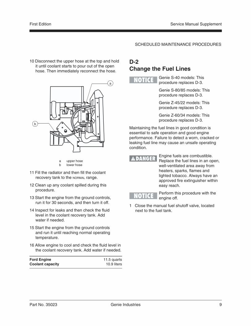
10 Disconnect the upper hose at the top and holdit until coolant starts to pour out of the openhose. Then immediately reconnect the hose.
a upper hoseb lower hose
11 Fill the radiator and then fill the coolantrecovery tank to the NORMAL range.
12 Clean up any coolant spilled during thisprocedure.
13 Start the engine from the ground controls,run it for 30 seconds, and then turn it off.
14 Inspect for leaks and then check the fluidlevel in the coolant recovery tank. Addwater if needed.
15 Start the engine from the ground controlsand run it until reaching normal operatingtemperature.
16 Allow engine to cool and check the fluid level inthe coolant recovery tank. Add water if needed.
Ford Engine 11.5 quartsCoolant capacity 10.9 liters
a
b
D-2Change the Fuel Lines
Genie S-40 models: Thisprocedure replaces D-3.
Genie S-80/85 models: Thisprocedure replaces D-3.
Genie Z-45/22 models: Thisprocedure replaces D-3.
Genie Z-60/34 models: Thisprocedure replaces D-3.
Maintaining the fuel lines in good condition isessential to safe operation and good engineperformance. Failure to detect a worn, cracked orleaking fuel line may cause an unsafe operatingcondition.
Engine fuels are combustible.Replace the fuel lines in an open,well-ventilated area away fromheaters, sparks, flames andlighted tobacco. Always have anapproved fire extinguisher withineasy reach.
Perform this procedure with theengine off.
1 Close the manual fuel shutoff valve, locatednext to the fuel tank.

10 Genie Industries Part No. 35023
Service Manual Supplement First Edition
SCHEDULED MAINTENANCE PROCEDURES
2 Remove and replace the fuel line hoses andclamps according to the following illustrations:
Fuel may be expelled underpressure. Wrap a cloth aroundfuel hoses to absorb leaking fuelbefore disconnecting them.
a carburetorb fuel filterc hose from the fuel filter to
the fuel pumpd hose from the fuel pump
to the fuel tank (not shown)
3 Clean up any fuel that may have spilled duringthis procedure.
4 Start the engine from the ground controls, theninspect the fuel filter and hoses for leaks.
If a fuel leak is discovered, keepany additional personnel fromentering the area and do notoperate the machine. Repairthe leak immediately.
a b c
d
D-3Check the Engine ValveClearance - Gasoline/LPG Models
Genie S-40 models: Thisprocedure replaces D-4.
Genie S-80/85 models: Thisprocedure replaces D-4.
Genie Z-45/22 models: Thisprocedure replaces D-4.
Genie Z-60/34 models: Thisprocedure replaces D-4.
Complete information to perform this procedure isavailable in the Ford LRG-423 2.3 Liter IndustrialEngine Service Manual (Ford number: PPD-194-287). Genie part number 33907.
D-4Check the Engine CylinderCompression- Gasoline/LPG Models
Genie S-40 models: Thisprocedure replaces D-5.
Genie S-80/85 models: Thisprocedure replaces D-5.
Genie Z-45/22 models: Thisprocedure replaces D-5.
Genie Z-60/34 models: Thisprocedure replaces D-5.
Complete information to perform this procedure isavailable in the Ford LRG-423 2.3 Liter IndustrialEngine Service Manual (Ford number: PPD-194-287). Genie part number 33907.
Part No. 35023 Genie Industries 11
First Edition Service Manual Supplement
SCHEDULED MAINTENANCE PROCEDURES
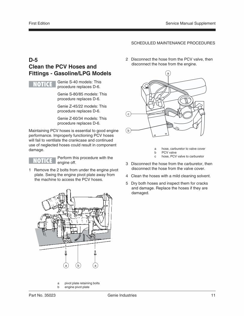
D-5Clean the PCV Hoses andFittings - Gasoline/LPG Models
Genie S-40 models: Thisprocedure replaces D-6.
Genie S-80/85 models: Thisprocedure replaces D-6.
Genie Z-45/22 models: Thisprocedure replaces D-6.
Genie Z-60/34 models: Thisprocedure replaces D-6.
Maintaining PCV hoses is essential to good engineperformance. Improperly functioning PCV hoseswill fail to ventilate the crankcase and continueduse of neglected hoses could result in componentdamage.
Perform this procedure with theengine off.
1 Remove the 2 bolts from under the engine pivotplate. Swing the engine pivot plate away fromthe machine to access the PCV hoses.
a pivot plate retaining boltsb engine pivot plate
ba a
2 Disconnect the hose from the PCV valve, thendisconnect the hose from the engine.
a hose, carburetor to valve coverb PCV valvec hose, PCV valve to carburetor
3 Disconnect the hose from the carburetor, thendisconnect the hose from the valve cover.
4 Clean the hoses with a mild cleaning solvent.
5 Dry both hoses and inspect them for cracksand damage. Replace the hoses if they aredamaged.
c
b
a

12 Genie Industries Part No. 35023
Service Manual Supplement First Edition
SCHEDULED MAINTENANCE PROCEDURES
D-6Replace the Timing Belt- Gasoline/LPG Models
Genie S-40 models: Thisprocedure replaces D-9.
Genie S-80/85 models: Thisprocedure replaces D-9.
Genie Z-45/22 models: Thisprocedure replaces D-9.
Genie Z-60/34 models: Thisprocedure replaces D-9.
Complete information to perform this procedure isavailable in the Ford LRG-423 2.3 Liter IndustrialEngine Service Manual (Ford number: PPD-194-287). Genie part number 33907.


S-40 Electrical Schematic -Gasoline/LPG Models
Service Manual Supplement
1
2
3
4
5
6
7
8
A B C D E F G H I J K L M N O
13 Genie Industries Part No. 35023

S-40 Electrical Schematic -Gasoline/LPG Models
Service Manual Supplement
1
2
3
4
5
6
7
8
O N M L K J I H G F E D C B A
Part No. 35023 Genie Industries 14
S-40 Electrical Schematic -Gasoline/LPG Models
Service Manual Supplement
Part No. 35023 Genie Industries 15
S-40 Ground Control Box Legend -Gasoline/LPG Models
Service Manual Supplement

16 Genie Industries Part No. 35023
S-40 Relay Panel Legend -Gasoline/LPG Models
Service Manual Supplement

Part No. 35023 Genie Industries 17
Service Manual Supplement
S-40 Platform Control Box Legend -Gasoline/LPG Models

S-80/85 Electrical Schematic -Gasoline/LPG Models
Service Manual Supplement
1
2
3
4
5
6
7
8
A B C D E F G H I J K L M N O
18 Genie Industries Part No. 35023
Part No. 35023 Genie Industries 19
S-80/85 Electrical Schematic -Gasoline/LPG Models
Service Manual Supplement
1
2
3
4
5
6
7
8
O N M L K J I H G F E D C B A
S-80/85 Electrical Schematic -Gasoline/LPG Models
Service Manual Supplement
Part No. 35023 Genie Industries 20
S-80/85 Ground Control Box Legend -Gasoline/LPG Models
Service Manual Supplement
21 Genie Industries Part No. 35023
S-80/85 Relay Panel Legend -Gasoline/LPG Models
Service Manual Supplement

Part No. 35023 Genie Industries 22
Service Manual Supplement
S-80/85 Platform Control Box Legend -Gasoline/LPG Models

Z-45/22 Electrical Schematic -Gasoline/LPG Models
Service Manual Supplement

Z-45/22 Electrical Schematic -Gasoline/LPG Models
Service Manual Supplement
1
2
3
4
5
6
7
8
A B C D E F G H I J K L M N O
23 Genie Industries Part No. 35023
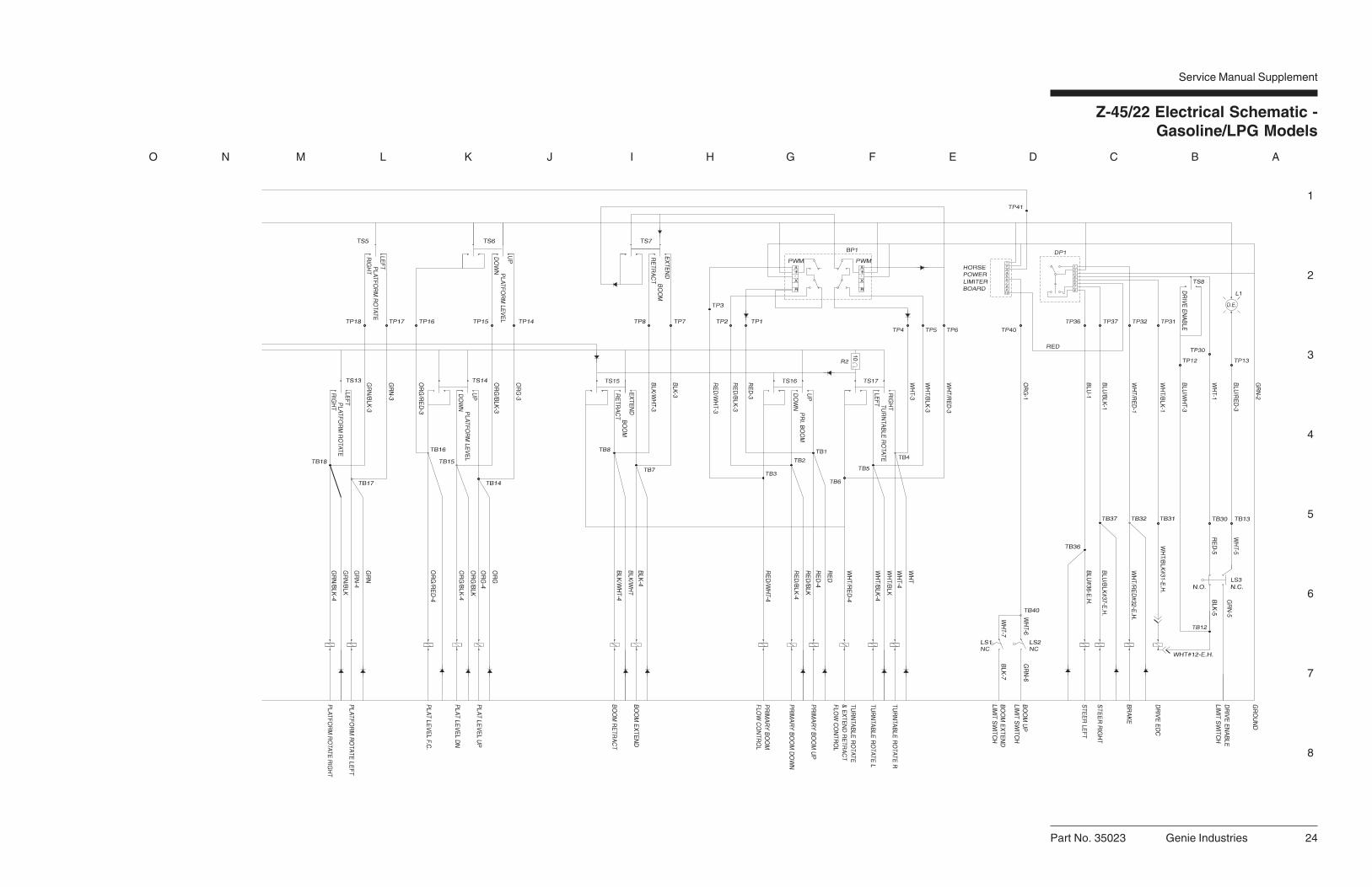
Z-45/22 Electrical Schematic -Gasoline/LPG Models
Service Manual Supplement
1
2
3
4
5
6
7
8
O N M L K J I H G F E D C B A
Part No. 35023 Genie Industries 24

Part No. 35023 Genie Industries 25
Z-45/22 Ground Control Box Legend -Gasoline/LPG Models
Service Manual Supplement
26 Genie Industries Part No. 35023
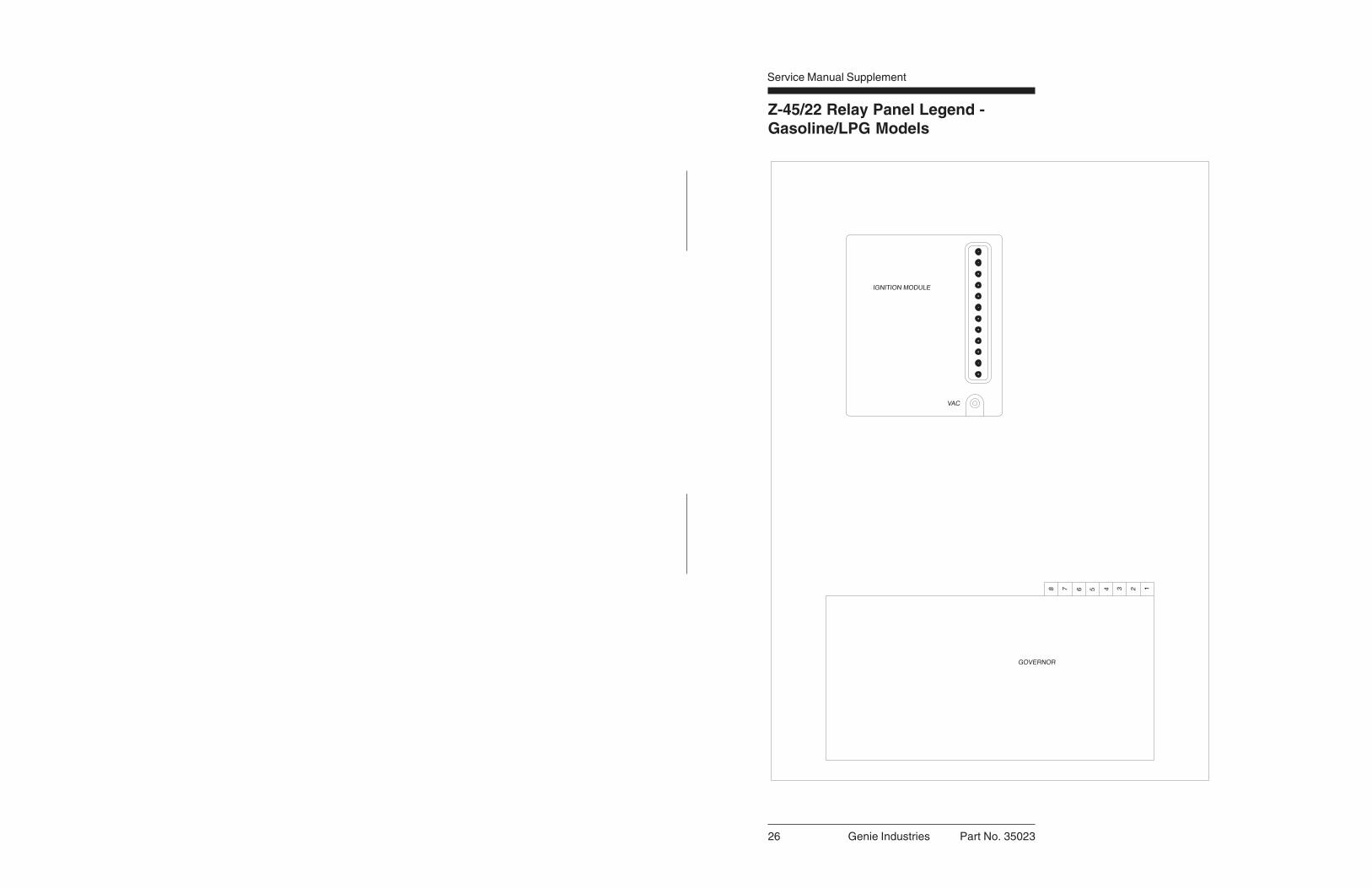
Z-45/22 Relay Panel Legend -Gasoline/LPG Models
Service Manual Supplement

Part No. 35023 Genie Industries 27
Service Manual Supplement
Z-45/22 Platform Control Box Legend -Gasoline/LPG Models
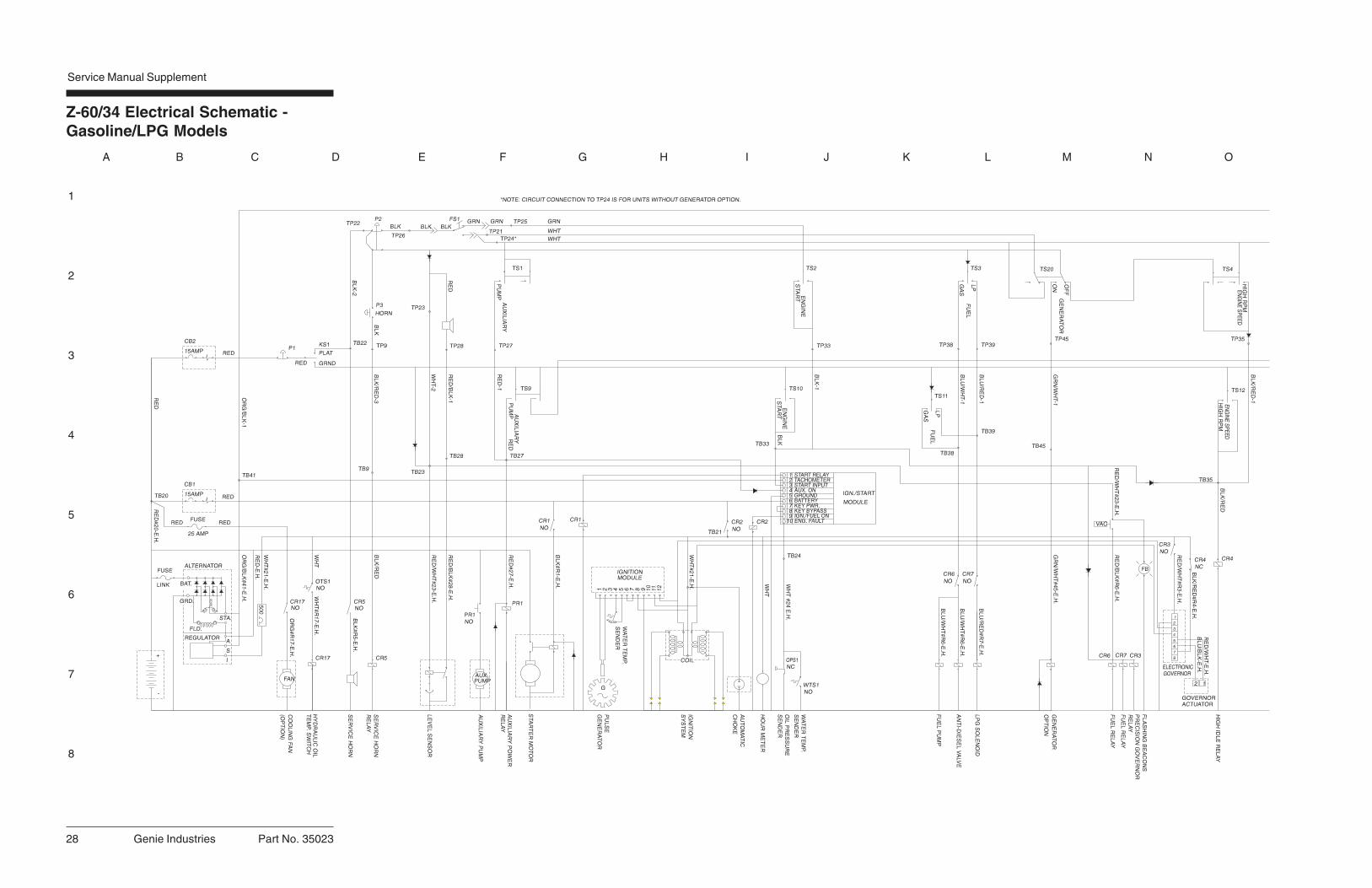
Z-60/34 Electrical Schematic -Gasoline/LPG Models
Service Manual Supplement
1
2
3
4
5
6
7
8
A B C D E F G H I J K L M N O
28 Genie Industries Part No. 35023

Z-60/34 Electrical Schematic -Gasoline/LPG Models
Service Manual Supplement
1
2
3
4
5
6
7
8
O N M L K J I H G F E D C B A
Part No. 35023 Genie Industries 29

Z-60/34 Electrical Schematic -Gasoline/LPG Models
Service Manual Supplement
Part No. 35023 Genie Industries 30
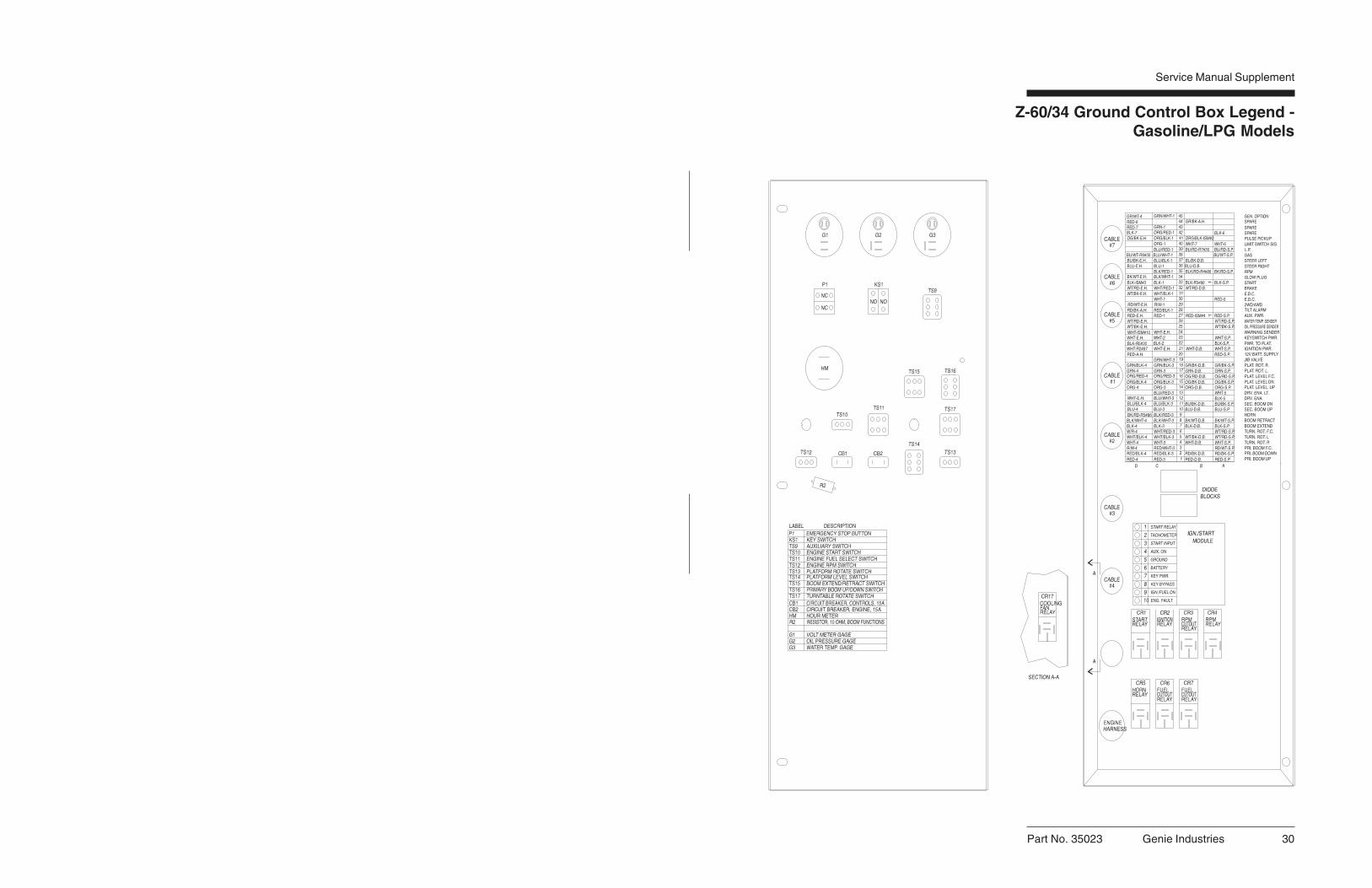
Z-60/34 Ground Control Box Legend -Gasoline/LPG Models
Service Manual Supplement

31 Genie Industries Part No. 35023
Z-60/34 Relay Panel Legend -Gasoline/LPG Models
Service Manual Supplement

Part No. 35023 Genie Industries 32
Z-60/34 Ground Control Box Legend -Gasoline/LPG Models
Service Manual Supplement

Part No. 35023 Genie Industries 33
First Edition Service Manual Supplement
Ford LRG-423 Engine
e
b c
f
g
d
110°
a
Governor actuator and linkagea clevis yokeb linkage rodc carburetord throttle plate shafte governor actuatorf actuator shaftg actuator arm
2 Fasten the lock nut and clevis yoke to thelinkage rod. Do not tighten the lock nutagainst the clevis yoke.
3 Loosen the fastener on the actuator arm.Rotate the actuator arm until it is at a110 degree angle to the linkage rod. Thentighten the actuator arm fastener.
7-1Governor Actuator
How to Set Up the GovernorActuator and Linkage
Adjustment of the governoractuator is only necessary whenthe governor actuator or thelinkage has been replaced.
1 Connect the linkage rod to the throttle plateshaft, then tighten the lock nut.
Genie S-40 models: This sectionreplaces Section 6.
Genie S-80/85 models: Thissection replaces Section 7.
Genie Z-45/22 models: Thissection replaces Section 7.
Genie Z-60/34 models: Thissection replaces Section 8.

34 Genie Industries Part No. 35023
First EditionService Manual Supplement
4 Position the linkage rod so that the throttle is inthe idle position. Then adjust the clevis yoke onthe linkage rod to obtain the proper length.Install the yoke onto the actuator arm.
5 With the throttle in the idle position and theactuator arm at a 110 degree angle to thelinkage, rotate the clevis yoke on the linkagerod two turns counterclockwise to pre-load thespring. Tighten the lock nut on the linkage rod.
6 Manually pull the actuator arm through a fullcycle to be sure that the linkage moves freely.Be sure that the linkage activates the throttleshaft to approximately half throttle.
The linkage must be free offriction and obstruction. Do notlet it rub against the engine,brackets or hoses.
Component damage hazard.If the throttle linkage is improperlyadjusted and allowed to reach fullthrottle, the engine will over-revand cause component damage.
FORD LRG-423 ENGINE
7-2Choke Adjustments
This engine is equipped with an electrically heatedautomatic choke. The choke has a poppet valve toenhance cold starting ability on LPG fuel.
Choke adjustments are affectedby climate. Richer adjustmentwill be necessary in colderclimates, leaner adjustmentin warmer climates.
Automatic Choke withPoppet ValveThe choke functions in both gasoline and LPGmode. The choke butterfly may be adjusted to afully closed (rich) position for colder climates andthe poppet valve will provide a flow path duringLPG fueled operation.
rich lean
Part No. 35023 Genie Industries 35
First Edition Service Manual Supplement
Flex Plate Removal1 Disconnect and remove the hose between
the carburetor venturi and the air cleaner.
2 Disconnect the linkage from the governor,then remove the governor linkage fromthe carburetor. Do not alter the length ofthe linkage.
3 Disconnect the wiring plug at the electronicdisplacement controller (EDC), located onthe drive pump.
4 Remove the mounting fasteners from theregulator mounting bracket, then pull thebracket up past the bell housing. Securethe bracket before continuing.
5 Support the drive pump with an appropriatelifting device. Then remove all of the pumpmounting plate to engine bell housing bolts.
6 Carefully pull the pump away from theengine and secure it from moving.
7 Remove the flex plate mounting fasteners,then remove the flex plate from the fly wheel.
How to Install the Flex Plate1 Install the flex plate onto the flywheel with the
raised spline towards the pump. Torque theflex plate mounting bolts to 34 ft-lbs (46 Nm).
2 Install the coupler onto the pump shaft with theset screw towards the pump. Leave a 1/4 inch(6.35 mm) gap between the coupler and pumpend plate.
3 Apply Loctite® removable thread sealant to thecoupler set screw. Torque the set screw to45 ft-lbs (61 Nm).
Component damage hazard. Donot force the drive pump duringinstallation or the flex plate teethmay become damaged.
4 Install the pump and torque the pump mountingplate fasteners to 34 ft-lbs (46 Nm).
FORD LRG-423 ENGINE
7-3Timing Adjustment
Complete information to perform this procedure isavailable in the Ford LRG-423 2.3 Liter IndustrialEngine Service Manual (Ford number: PPD-194-287). Genie part number 33907.
7-4Carburetor Adjustment
Complete information to perform this procedure isavailable in the Ford LRG-423 2.3 Liter IndustrialEngine Service Manual (Ford number: PPD-194-287). Genie part number 33907.
7-5RPM Adjustment
Refer to Maintenance Procedures, B-3, Check andAdjust the Engine RPM.
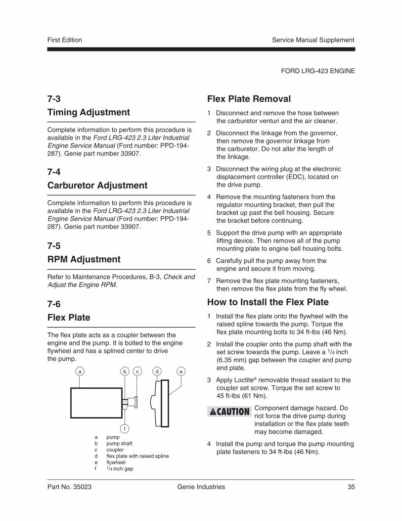
7-6Flex Plate
The flex plate acts as a coupler between theengine and the pump. It is bolted to the engineflywheel and has a splined center to drivethe pump.
a pumpb pump shaftc couplerd flex plate with raised splinee flywheelf 1/4 inch gap
a b c d e
f
36 Genie Industries Part No. 35023
First EditionService Manual Supplement
7-8Vacuum Switch
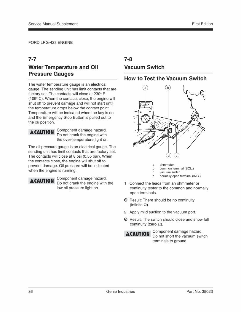
How to Test the Vacuum Switch
a ohmmeterb common terminal (SOL.)c vacuum switchd normally open terminal (ING.)
1 Connect the leads from an ohmmeter orcontinuity tester to the common and normallyopen terminals.
Result: There should be no continuity(infinite Ω).
2 Apply mild suction to the vacuum port.
Result: The switch should close and show fullcontinuity (zero Ω).
Component damage hazard.Do not short the vacuum switchterminals to ground.
FORD LRG-423 ENGINE
7-7Water Temperature and OilPressure Gauges
The water temperature gauge is an electricalgauge. The sending unit has limit contacts that arefactory set. The contacts will close at 230o F(109o C). When the contacts close, the engine willshut off to prevent damage and will not start untilthe temperature drops below the contact point.Temperature will be indicated when the key is onand the Emergency Stop Button is pulled out tothe ON position.
Component damage hazard.Do not crank the engine withthe over-temperature light on.
The oil pressure gauge is an electrical gauge. Thesending unit has limit contacts that are factory set.The contacts will close at 8 psi (0.55 bar). Whenthe contacts close, the engine will shut off toprevent damage. Oil pressure will be indicatedwhen the engine is running.
Component damage hazard.Do not crank the engine with thelow oil pressure light on.
a b
cd

U.S.A.18340 NE 76th Street
P.O. Box 69
Redmond, Washington
98073-0069
EuropeBrunel Drive
Newark
Nottinghamshire
NG24 2EG England