
FORCINA HALL - HVAC AND ROOF REPLACEMENT THE COLLEGE …
434
FORCINA HALL - HVAC AND ROOF REPLACEMENT THE COLLEGE OF NEW JERSEY 2000 PENNINGTON ROAD EWING, NJ 08628 PROJECT SPECIFICATIONS VOLUME 2 OF 3 DIVISION 23 ISSUED FOR CONSTRUCTION January 15, 2018 Prepared by: DLB Associates Consulting Engineers, P.C. 265 Industrial Way West Eatontown, NJ 07724 (DLB # 47210)
Transcript of FORCINA HALL - HVAC AND ROOF REPLACEMENT THE COLLEGE …

FORCINA HALL - HVAC AND ROOF REPLACEMENT
THE COLLEGE OF NEW JERSEY
2000 PENNINGTON ROAD
EWING, NJ 08628
PROJECT SPECIFICATIONS
VOLUME 2 OF 3
DIVISION 23
ISSUED FOR CONSTRUCTION
January 15, 2018
Prepared by:
DLB Associates Consulting Engineers, P.C.
265 Industrial Way West
Eatontown, NJ 07724
(DLB # 47210)

TCNJ FORCINA HALL - HVAC AND ROOF REPLACEMENT dlb # 47210
ISSUED FOR CONSTRUCTION January 15, 2018

TCNJ FORCINA HALL - HVAC AND ROOF REPLACEMENT dlb # 47210
ISSUED FOR CONSTRUCTION January 15, 2018
TABLE OF CONTENTS
SECTION DESCRIPTION
TABLE OF CONTENTS TOC - 1
DIVISION 23 – HEATING VENTILATING AND AIR CONDITIONING
230100 BASIC MECHANICAL REQUIREMENTS
230130 HVAC AIR DISTRIBUTION SYSTEM CLEANING
230513 COMMON MOTOR REQUIREMENTS FOR HVAC EQUIPMENT
230517 SLEEVES AND SLEEVE SEALS FOR PIPING
230518 ESCEUTCHEONS FOR HVAC PIPING
230519 METERS AND GAGES FOR HVAC PIPING
230523 GENERAL DUTY VALVES FOR HVAC
230529 HANGERS AND SUPPORTS FOR HVAC PIPING AND EQUIPMENT
230533 HEAT TRACING FOR HVAC PIPING
230548 VIBRATION CONTROLS FOR HVAC
230553 IDENTIFICATION FOR HVAC PIPING AND EQUIPMENT
230593 TESTING, ADJUSTING, AND BALANCING FOR HVAC
230713 DUCT INSULATION
230716 HVAC EQUIPMENT INSULATION
230719 HVAC PIPING INSULATION
230900 INSTRUMENTATION AND CONTROLS FOR HVAC
232113 HYDRONIC PIPING
232116 HYDRONIC PIPING SPECIALTIES
232123 HYDRONIC PUMPS
232213 STEAM AND CONDENSATE HEATING PIPING AND VALVES
232216 STEAM AND CONDENSATE PIPING SPECIALTIES
232223 STEAM CONDENSATE PUMPS
232513 WATER TREATMENT FOR CLOSED-LOOP HYDRONIC SYSTEM
233113 METAL DUCTS
233119 HVAC CASINGS
233300 AIR DUCT ACCESSORIES
233423 HVAC POWER VENTILATORS
233600 AIR TERMINAL UNITS
235700 HEAT EXCHANGERS FOR HVAC
237313 CUSTOM OUTDOOR AIR-HANDLING UNITS
238219 FAN COIL UNITS
238239 CABINET UNIT HEATERS

TCNJ FORCINA HALL - HVAC AND ROOF REPLACEMENT dlb # 47210
ISSUED FOR CONSTRUCTION January 15, 2018

TCNJ FORCINA HALL - HVAC AND ROOF REPLACEMENT dlb # 47210
ISSUED FOR CONSTRUCTION January 15, 2018
BASIC MECHANICAL REQUIREMENTS 230100 - 1
SECTION 230100 - BASIC MECHANICAL REQUIREMENTS
PART 1 - GENERAL
1.1 RELATED DOCUMENTS
A. Drawings and general provisions of the Contract, including
General and Supplementary Conditions and Division 01
Specification Sections, apply to this Section.
1.2 INTENT
A. These specifications shall be used by all Contractors and
Subcontractors for the construction of this project. This
section applies to all sections of Division 23 of this project,
except as specified otherwise in each individual section.
B. Bidding Requirements, Conditions of the Contract and Project-
General Requirements are made part of Division 23, Mechanical
Work.
C. Continuous Occupancy: All buildings shall be considered
occupied during the life of this Contract, unless otherwise
indicated in construction documentation. When interference is
unavoidable, the Contractor shall:
1. Schedule work in advance with the Owner‘s representative.
2. Make temporary connections when required to maintain
uninterrupted electrical, plumbing, HVAC service, and
process utilities service.
3. Perform work as quietly as possible to avoid unnecessary
disturbance.
4. Proposed work methods, producing high noise levels, dust or
potential hazards to occupants, must be reviewed with
Owner‘s representative prior to commencement.
1.3 SCOPE OF WORK
A. The work to be provided under this specification includes, but
is not limited to: the furnishing, delivery, unloading,
handling, storing, protection, erecting, installing, adjusting,
testing, and cleaning of all equipment, materials, and
apparatus which are required, complete in all respects and

TCNJ FORCINA HALL - HVAC AND ROOF REPLACEMENT dlb # 47210
ISSUED FOR CONSTRUCTION January 15, 2018
BASIC MECHANICAL REQUIREMENTS 230100 - 2
fully adjusted and capable of operating as shown on the
drawings and/or in the specifications.
B. Furnishing of Equipment and Materials
1. Owner Furnished and Contractor Installed (OFCI) Equipment
designated in each individual section, and/or identified on
the drawings, will be furnished by the Owner for
installation under Division 23 of the contract. Contractor
to inspect upon delivery, note any damages; any later
damages are responsibility of this Contractor. Mechanical
Contractor shall at proper time move, uncrate, set in
place, align, and/or make all necessary connections,
including the installation of subassemblies and/or
accessories provided with the equipment. Provide shut-off
valves, unions, traps, vibration isolators, etc., as
applicable, and/or as required, for this equipment (refer
to drawings for details). The manufacturer of equipment
purchased may vary slightly from that specified and/or
indicated, and therefore equipment may require some
rearranging from that indicated. Connections to such
rearranged equipment shall be made without additional cost
to the Owner.
2. Furnished and Installed by this Contractor: Miscellaneous
equipment is defined as all equipment furnished under this
section and/or other sections of this specification. See
each specific section, and/or drawings, for information
pertaining to connections to miscellaneous equipment.
1.4 RELATED WORK
A. All work required in the specifications listed below:
1. Project drawings.
2. All project specifications.
1.5 REFERENCE CODES AND STANDARDS
A. All work and equipment provided under this contract shall be
installed in strict accordance with all Federal, State, Local
Codes, Laws, Ordinances, Rules and Regulations of public
administrative authorities, including all health and safety
codes, environmental, and OSHA requirements. The Contractor
shall obtain approval of all systems before starting work.
B. In accordance with the General Conditions of the Contract, the
bidder shall inform the owner of all discrepancies that he

TCNJ FORCINA HALL - HVAC AND ROOF REPLACEMENT dlb # 47210
ISSUED FOR CONSTRUCTION January 15, 2018
BASIC MECHANICAL REQUIREMENTS 230100 - 3
observes between the applicable codes and the specifications
and drawings. The bidder shall submit such data to the owner
in writing before the end of bidding period. The bidder shall
include in his bid price an allowance for the difference in
cost required to satisfy all code requirements.
C. All violations of Code Requirements not identified during the
bidding period shall be corrected by the Contractor at no cost
to the owner.
D. References made herein, or in any of the Mechanical
Specifications listed above, to standards, codes,
specifications, or recommendations of various technical
societies, trade organizations, or governmental agencies are to
the edition in effect at the time of the proposal, including
all addenda.
E. Code changes: If code changes occurring between time of
proposal and date of permit issue, and the Contractor has
delayed in the acquisition of his permits, the Contractor shall
hold the owner free from additional expense resulting from such
code change.
F. Detailed listing of reference codes and standards:

TCNJ FORCINA HALL - HVAC AND ROOF REPLACEMENT dlb # 47210
ISSUED FOR CONSTRUCTION January 15, 2018
BASIC MECHANICAL REQUIREMENTS 230100 - 4
REFERENCED CODES AND STANDARDS
American Bearing Manufacturers Association (ABMA)
ABMA STD 9 Load Ratings and Fatigue Life for Ball
Bearings
ABMA STD 11 Load Ratings and Fatigue Life for Roller
Bearings
Anti-Friction Bearing Manufacturers Association (AFBMA)
AFBMA 9 Load Ratings and Fatigue Life for Ball Bearings
AFBMA 11 Load Ratings and Fatigue Life for Roller Bearings
American Gas Association (AGA)
AGA Z21.22 Relief Valves and Automatic Gas Shutoff
Devices for Hot Water Supply Systems
American National Standards Institute (ANSI)
ANSI B1.1 Unified Inch Screw Threads
ANSI B16.5 Pipe Flanges and Flanged Fittings
ANSI S1.1 Acoustical Terminology (Including Mechanical
Shock and Vibration)
ANSI S1.13 Methods for Measurement of Sound Pressure
Levels
ANSI S1.8 Preferred Reference Quantities for Acoustical
Levels
ANSI Z358.1 Emergency Eye Wash and Shower Equipment
Air Conditioning and Refrigeration Institute (ARI)
ARI 1010 Drinking Fountains and Self-Contained
Mechanically Refrigerated Drinking Water Coolers
ARI 270 Sound Rating of Outdoor Unitary Equipment
ARI 410 Forced-Circulation Air-Cooling and Air-Heating
Coils
ARI 430 Standard for Central-Station Air-Handling Coils
ARI 575 Measuring Machinery Sound Within Equipment Rooms
ARI 610 Central system Humidifiers
ARI 620 Standard for Self-Contained Humidifiers

TCNJ FORCINA HALL - HVAC AND ROOF REPLACEMENT dlb # 47210
ISSUED FOR CONSTRUCTION January 15, 2018
BASIC MECHANICAL REQUIREMENTS 230100 - 5
ARI 640 Standard for Commercial and Industrial Humidifiers
ARI Guideline D Application and Installation of Central
Station Air-Handling Units
ARI 850 Commercial and Industrial Air Filter Equipment
Acoustical Society of America
ASA 16 (ANSI S1.36) Survey Methods for Determination of Sound
Power Levels of Noise Sources
ASA 47 (ANSI S1.4) Specification for Sound Level Meters
ASA 49 (ANSI S12.1) Preparation of Standard Procedures to
Determine the Noise Emission from Sources
American Society of Heating, Refrigerating and Air Conditioning
Engineers, Inc. (ASHRAE)
ASHRAE 33 Methods for Testing Forced Circulation Air Cooled and
Air Heating Coils
ASHRAE 52.1 Method of Testing Air Cleaning Devices used in
General Ventilation for Removing Particulate Matter
ASHRAE 68 Method of Testing In-Duct Sound Power Measurement
Procedure for Fans
ASHRAE 70 Method of Testing for Rating the Air Flow Performance
of Outlets and Inlets
ASHRAE Handbook Systems Volume, Chapter "Sound and Vibration
Control"
ASHRAE 90.1 Energy Standard for Buildings Except Low-Rise
Residential Buildings
American Society of Mechanical Engineers (ASME)
ASME Boilers and Pressure Vessel Codes, SEC 8-D-Rules for
Construction of Pressure Vessels
ASME Boiler and Pressure Vessel Codes, SEC 9 - Qualification
Standard for Welding and Brazing Procedures, Welders, Brazers,
and Welding and Brazing Operators
ASME Boiler and Pressure Vessel Code, Section IV
ASME Boiler and Pressure Vessel Code, Section VII, Division 1
ASME A112.6.1 Supports for Off-the-Floor Plumbing Fixtures for
Public Use

TCNJ FORCINA HALL - HVAC AND ROOF REPLACEMENT dlb # 47210
ISSUED FOR CONSTRUCTION January 15, 2018
BASIC MECHANICAL REQUIREMENTS 230100 - 6
ASME A112.18.1 Finished and Rough Brass Plumbing Fixtures
Fittings
ASME A112.19.1 Enameled Cast Iron Plumbing Fixtures
ASME A112.19.2 Vitreous China Plumbing Fixtures
ASME A112.19.3 Stainless Steel Plumbing Fixtures (Designed for
Residential Use)
ASME A112.19.5 Trim for Water-Closet Bowls, Tanks, and Urinals
ASME A112.21.1 Floor Drains
ASME A112.21.2 Roof Drains
ASME A112.26.1 Water Hammer Arrestors
ASME B16.18 Cast Copper Alloy Solder Joint Pressure Fittings
ASME B16.22 Wrought Copper and Copper Alloy Solder Joint
Pressure Fittings
ASME B16.22 Wrought Copper and Bronze Solder Joint Pressure
Fittings
ASME B16.23 Cast Copper Alloy Solder Joint Drainage Fittings
- DWV
ASME B16.26 Cast Bronze Fittings for Flared Copper Tubes
ASME B16.29 Wrought Copper and Wrought Copper Alloy Solder
Joint Drainage Fittings - DWV
ASME B16.3 Malleable Iron Threaded Fittings Class 150 and
300
ASME B31.1 Code for Power Piping
ASME B31.5 Refrigeration Piping
ASME B31.9 Building Services Piping
ASME SEC IX Welding and Blazing Qualifications.
American Society of Sanitary Engineers (ASSE)
ASSE 1011 Hose Connection Vacuum Breakers
ASSE 1012 Backflow Preventers with Immediate Atmospheric Vent
ASSE 1013 Backflow Preventers, Reduced Pressure Principle
ASSE 1019 Wall Hydrants, Frost Proof Automatic Draining Anti-
Backflow Types
American Society for Testing and Materials (ASTM)
ASTM A 36 Structural Steel

TCNJ FORCINA HALL - HVAC AND ROOF REPLACEMENT dlb # 47210
ISSUED FOR CONSTRUCTION January 15, 2018
BASIC MECHANICAL REQUIREMENTS 230100 - 7
ASTM A 53 Pipe, Steel, Black and Hot-Dipped Zinc Coated,
Welded and Seamless
ASTM A 74 Cast Iron Soil Pipe and Fittings
ASTM A 90 Weight of Coating on Zinc-Coated (Galvanized)
Iron or Steel Articles
ASTM A 105 Forging, Carbon Steel, for Piping Components
ASTM A 167 Stainless and Heat-Resisting Chromium-Nickel
Steel Plate, Sheet, and Strip
ASTM A 234 Pipe Fittings of Wrought Carbon Steel and Alloy
Steel for Moderate and Elevated Temperatures
ASTM A 366 Steel, Sheet, Carbon, Cold Rolled, Commercial
Quality
ASTM A 480 General Requirements for Flat-Rolled Stainless
and Heat-Resisting Steel Plate, Sheet, and Strip
ASTM A 525 General Requirements for Steel Sheet, Zinc-Coated
(Galvanized) by the Hot-Dip Process
ASTM A 527 Steel Sheet, Zinc-Coated (Galvanized) by Hot-Dip
Process, Lock Forming Quality
ASTM A 568 Steel, Sheet, Carbon, and High-Strength, Low-
Alloy, Hot-Rolled and Cold-Rolled
ASTM A 569 Steel, Carbon (0.15 Maximum, Percent), Hot-Rolled
Sheet and Strip, Commercial Quality
ASTM B 32 Solder Metal
ASTM B 42 Seamless Copper Pipe
ASTM B 88 Seamless Copper Water Tube
ASTM B 209 Aluminum and Aluminum-Alloy Sheet and Plate
ASTM B 306 Copper Drainage Tube (DWV)
ASTM C 14 Concrete Sewer, Storm Drain, and Culvert Pipe
ASTM C 177 Steady-State Heat Flux Measurements and Thermal
Transmission Properties by Means of the Guarded Hot Plate
Apparatus
ASTM C 240 Testing Cellular Glass Insulation Block
ASTM C 443 Joints for Circular Concrete Sewer and Culvert
Pipe, Using Rubber Gaskets
ASTM C 478 Precast Reinforced Concrete Manhole Sections
ASTM C 518 Steady-State Heat Flux Measurements and Thermal
Transmission Properties by Means of the Heat Flow Method

TCNJ FORCINA HALL - HVAC AND ROOF REPLACEMENT dlb # 47210
ISSUED FOR CONSTRUCTION January 15, 2018
BASIC MECHANICAL REQUIREMENTS 230100 - 8
ASTM C 533 Calcium Silicate Block and Pipe Thermal
Insulation
ASTM C 534 Pre-formed Flexible Ellastomeric Cellular Thermal
Insulation in the Sheet and Tublar Form
ASTM C 547 Mineral Fiber Pre-formed Pipe Insulation
ASTM C 552 Cellular Glass Thermal Insulation
ASTM C 564 Rubber Gaskets for Cast Iron Soil Pipe and
Fittings
ASTM C 578 Pre-formed, Cellular Polystyrene Thermal
Insulation
ASTM C 591 Unfaced Pre-formed, Rigid Cellular Polyurethane
Thermal Insulation
ASTM C 592 Mineral Fiber Blanket Thermal Insulation for
Commercial and Industrial Applications
ASTM C 610 Expanded Perlite Block and Pipe Thermal
Insulation
ASTM C 612 Mineral Fiber Block and Board Thermal Insulation
ASTM C 795 Thermal Insulation for Use in Contact with
Austenitic Stainless Steel
ASTM C 921 Properties of Jacketing Materials for Thermal
Insulation
ASTM D 1056 Flexible Cellular Materials - Sponge or Expanded
Rubber
ASTM D 1667 Flexible Cellular Materials - Vinyl Chloride
Polymers and Copopolymers (Closed-Cell Foam)
ASTM D 1785 Poly (Vinyl Chloride) (PVC) Plastic Pipe,
Schedules 40, 80, and 120
ASTM D 2235 Solvent Cement for Acrylonitrile-Butadiene-
Styrene (ABS) Plastic Pipe and Fittings
ASTM D 2241 Poly (Vinyl Chloride) (PVC) Pressure-Rated Pipe
(SDR-Series)
ASTM D 2310 Machine-Made Reinforced Thermosetting Resin Pipe
ASTM D 2466 Poly (Vinyl Chloride) (PVC) Plastic Pipe
fittings, Schedule 40
ASTM D 2467 Socket-Type Poly (Vinyl Chloride) (PVC) Plastic
Pipe Fittings, Schedule 80
ASTM D 2680 Acrylonitrile-Butadiene-Styrene (ABS) and Poly
(Vinyl Chloride) (PVC) Composite-Sewer Piping

TCNJ FORCINA HALL - HVAC AND ROOF REPLACEMENT dlb # 47210
ISSUED FOR CONSTRUCTION January 15, 2018
BASIC MECHANICAL REQUIREMENTS 230100 - 9
ASTM D 2683 Socket-Type Polyethylene Fittings for Outside
Diameter-Controlled Polyethylene Pipe and Tubing
ASTM D 2751 Acrylonitrile-Butadiene-Styrene (ABS) Sewer Pipe
and Fittings
ASTM D 2842 Water Absorption of Rigid Cellular Plastics
ASTM D 2855 Making Solvent-Cemented Joints with Poly (Vinyl
Chloride) (PVC) Pipe and Fittings
ASTM D 3309 Polybutylene (PB) Plastic Hot-and Cold-Water
Distribution Systems
ASTM E 477 Method of Testing Duct Liner Materials and
Prefabricated Silencers for Acoustical and Airflow Performance
ASTM E 596 Method of Laboratory Measurement of the Noise
Reduction of Sound Isolating Enclosures
ASTM E 84 Surface Burning Characteristics of Building
Materials
ASTM E 90 Method for Laboratory Measurement of Airborne
Sound Transmission of Building Partitions
ASTM E 96 Water Vapor Transmission of Materials
ASTM F 477 Elastomeric Seals (Gaskets) for Joining Plastic
Pipe
ASTM F 708 Design and Installation of Rigid Pipe Hangers
ASTM F 845 Plastic Insert Fittings for Polybutylene (PB)
Tubing
ASTM F 876 Crosslinked Polyethylene (PEX) Tubing
ASTM F 877 Crosslinked Polyethylene (PEX) Plastic Hot- and
Cold-Water Distribution Systems
American Welding Society, Inc. (AWS)
AWS A5.8 Brazing Filler Metal
AWS D1.1 Structural Welding Code
AWS D9.1 Welding of Sheet Metal
AWS D10.9 Specifications for Qualification of Welding Procedures
and Welders for Piping and Tubing
American Waterworks Association, Inc. (AWWA)
AWWA C105 Polyethylene Encasement for Ductile Iron Piping for
Water and Other Liquids

TCNJ FORCINA HALL - HVAC AND ROOF REPLACEMENT dlb # 47210
ISSUED FOR CONSTRUCTION January 15, 2018
BASIC MECHANICAL REQUIREMENTS 230100 - 10
AWWA C110 Ductile-Iron and Grey-Iron Fittings 3 in. through 48
in., for Water and Other Liquids
AWWA C111 Rubber-Gasket Joints for Ductile Iron and Grey-Iron
Pressure Pipe and Fittings
AWWA C151 Ductile-Iron Pipe, Centrifugally Cast in Metal Molds
or Sand-Lined Molds, for Water or Other Liquids
AWWA C506 Backflow Prevention Devices - Reduced Pressure
Principle and Double Check Valve Types
AWWA C651 Disinfecting Water Mains
Cast Iron Sanitary Pipe Institute (CISPI)
CISPI 301 Cast Iron Soil Pipe and Fittings for Hubless Cast Iron
Sanitary Systems
CISPI 310 Joints for Hubless Cast Iron Sanitary Systems
Factory Mutual Engineering and Research Corporation (FM)
FM 2-8N Installation of Sprinkler System
Institute of Environmental Sciences (IES)
IES-RP-CC-001 Recommended Practices
IES-RP-CC-001.3 Recommended Practices
Manufacturers Standardization Society of the Valve and Fittings
Industry (MSS)
MSS SP-110 Ball Valves Threaded, Socket-Welding, Solder
Joint, Grooved and Flared Ends
MSS SP-58 Pipe Hangers and Supports - Materials, Design and
Manufacture
MSS SP-67 Butterfly Valves
MSS SP-69 Pipe Hangers and Supports - Selection and Application
MSS SP-70 Cast Iron Gate Valves, Flanged and Threaded Ends
MSS SP-71 Cast Iron Swing Check Valves, Flanged and Threaded
Ends
MSS SP-80 Bronze Gate, Globe, Angle and Check Valves
MSS SP-85 Cast Iron Globe & Angle Valves, Flanged and Threaded
Ends

TCNJ FORCINA HALL - HVAC AND ROOF REPLACEMENT dlb # 47210
ISSUED FOR CONSTRUCTION January 15, 2018
BASIC MECHANICAL REQUIREMENTS 230100 - 11
MSS SP-89 Pipe Hangers and Supports - Fabrication and
Installation Practices
National Environmental Balancing Bureau (NEBB)
NEBB Procedural Standards for Measuring Sound and Vibration
National Electrical Manufacturers Association (NEMA)
NEMA MG1 Motors and Generators
National Fire Protection Association (NFPA)
NFPA 10 Portable Fire Extinguishers
NFPA 13 Installation of Sprinkler Systems
NFPA 14 Installation of Standpipe and Hose Systems
NFPA 15 Water Spray Fixed Systems
NFPA 22 Water Tanks for Private Fire Protection
NFPA 24 Installation of Private Fire Service Mains and Their
Appurtenances
NFPA 54 National Fuel Gas Code
NFPA 70 National Electrical Code
NFPA 90A Installation of Air Conditioning and Ventilating
Systems
NFPA 90B Installation of Warm Air Heating and Air Conditioning
Systems
NFPA 91 Installation of Blower and Exhaust Systems for Dust
and Vapor Removal or Conveying
NFPA 92A Smoke Control Systems
NFPA 96 Installation of Equipment for the Removal of Smoke and
Grease-Laden Vapors from Commercial Cooking Equipment
NFPA 214 Water Cooling Towers
NFPA 231 General Storage
NFPA 231C Rack Storage Materials
NFPA 255 Surface Burning Characteristics of Building Materials
NFPA 318 Protection of Clean Rooms
National Insulation Standards (NAIMA)

TCNJ FORCINA HALL - HVAC AND ROOF REPLACEMENT dlb # 47210
ISSUED FOR CONSTRUCTION January 15, 2018
BASIC MECHANICAL REQUIREMENTS 230100 - 12
National Institute of Standards and Technology (NIST)
PS 15 Voluntary Product Standard for Custom Contact-Molded
Reinforced-Polyester Chemical Resistant Process Equipment
Plumbing and Drainage Institute (PDI)
PDI G-101 Testing and Rating Procedure for Grease Interceptors
with Appendix of Sizing and Installation Data.
PDI WH-201 Water Hammer Arrestors
Sheet Metal and Air Conditioning Contractors National Association,
Inc. (SMACNA)
SMACNA Fibrous Glass Duct Construction Standards
SMACNA HVAC Air Duct Leakage Test Manual
SMACNA HVAC Duct Construction Standards - Metal and Flexible
SMACNA Metal Duct Construction Standards
Underwriters Laboratories Inc. (UL)
UL Fire Resistance Directory
UL 181 Factory-Made Air Ducts and Connectors
UL 33 Heat Responsive Links for Fire-Protection Service
UL 486 Wire Connectors and Soldering Lugs for use with Copper
Conductors
UL 555 Fire Dampers and Ceiling Dampers
UL 586 Test Performance of High Efficiency Particulate Air
Filter Units
UL 555S Leakage Rated Dampers for Use in Smoke Control Systems
UL 723 Surface Burning Characteristics of Building Materials
UL 867 Electronic Air Cleaners
UL 900 Test Performance of Air Filter Units
1.6 QUALITY ASSURANCE
A. Architect/Engineers Drawings: The Contractor shall be guided
in his work by all architectural, structural, mechanical, HVAC,
electrical, plumbing, and fire protection drawings and
specifications issued by the owner for this project.

TCNJ FORCINA HALL - HVAC AND ROOF REPLACEMENT dlb # 47210
ISSUED FOR CONSTRUCTION January 15, 2018
BASIC MECHANICAL REQUIREMENTS 230100 - 13
1. All drawings are part of the Contract, and drawings and
specifications shall be considered as complementary so that
anything shown upon one, or described by the other, or
fairly implied by either or both, shall be done and
performed the same as if shown upon and described by both.
2. Contract drawings for mechanical work are in part
diagrammatic, intended to convey the scope of work and
indicate general arrangement of equipment, ducts, conduits,
piping, and approximate sizes and locations of equipment
and outlets. Mechanical trades shall follow these drawings
in laying out their work, consult general construction
drawings to familiarize themselves with all conditions
affecting their work, and shall verify spaces in which
their work will be installed. Coordinate work with other
trades as job conditions reasonably require.
3. Where job conditions require reasonable changes in
indicated locations and arrangement, make such changes
without extra cost to Owner, but DO NOT proceed without
informing and getting concurrence from the owner.
4. The drawings are not intended to be scaled for roughing in
measurements nor as shop drawings.
5. The installation details, instructions, and recommendations
of the manufacturer of the product used, modified to obtain
the best end result, shall form the basis of attending
installation of the products for usage on this project
except where definite and specific instructions are set
forth therein or details are shown on plans.
B. Ordinances, Permits, and Codes:
1. All work shall be executed in accordance with the local,
State, and/or other attending rules and regulations
applicable to the trade affected and be subject to the
inspection of these departments.
2. Obtain all permits and licenses required for work performed
under Division 23 and pay all fees in connection with same.
Turn over all documents to the Owner‘s representative.
3. After entering into contract, this Contractor shall be
responsible to complete all work necessary to comply with
such governing codes, regulations, and ordinances without
extra charge to the owner.
C. Certification and Qualification
1. Contractor, Subcontractor, Vendor, and Manufacturer shall
provide proof of certification to applicable standards as
called for in this and each section of the specifications
upon request by the owner. All costs associated with the

TCNJ FORCINA HALL - HVAC AND ROOF REPLACEMENT dlb # 47210
ISSUED FOR CONSTRUCTION January 15, 2018
BASIC MECHANICAL REQUIREMENTS 230100 - 14
failure to provide requested certification shall be
included at no additional cost to the owner.
2. The Contractor shall certify compliance with the submittal
requirements of section 1.6 of this specification.
3. The Contractor shall certify their capabilities and
experience shall be in an area of trade of the required for
this project and this Contract.
4. All Contractors and Suppliers shall be qualified to comply
with all requirements of this work that are applicable,
unless otherwise acceptable to the owner.
5. All work performed by qualified Contractors and Equipment
Suppliers shall be in accordance with the approved
instructions and procedures of manufacturers of equipment
and materials provided.
6. The owner or its representative shall maintain the right of
access to the Equipment Supplier's records and/or
facilities for the reason of auditing for compliance to
quality system requirements.
7. The Contractor and Supplier shall submit an uncontrolled
copy of his Quality Assurance/Control Manual or program
description. The Quality Assurance Manual or other written
program description shall provide for implementation of the
requirements listed in these specifications. When an
evaluation by the owner determines that his Quality
Assurance/Control program does not need to address all of
the Quality Program Requirements listed, exception may be
taken by submitting a brief statement of justification for
each requirement considered not applicable. The owner has
the sole right to accept or reject any exceptions
recommended by the Contractor or Supplier.
8. Suppliers of equipment shall impose quality requirements of
this specification on lower tier suppliers consistent with
the importance and complexity of the product being supplied
by the lower tier supplier's quality related operations
consistent with the nature and scope of the work or service
provided by the lower tier supplier. The Contractor,
Suppliers, and their subtier suppliers are subject to
inspection of material and records by the owner prior to
shipment, to verify adequate implementation and compliance.
9. Contractors shall give five (5) working days’ notice of the
shipment to the owner prior to shipment. Acceptance of
material and workmanship by the ownerM shall be dependent
upon acceptable site inspection.
10. Quality related documentation and records shall be in
accordance with the requirements of submittal section. All
certified reports and required documentation shall be
legible and reproducible.

TCNJ FORCINA HALL - HVAC AND ROOF REPLACEMENT dlb # 47210
ISSUED FOR CONSTRUCTION January 15, 2018
BASIC MECHANICAL REQUIREMENTS 230100 - 15
1.7 SUBMITTAL REQUIREMENTS
A. Submit for review and approval manufacturer's material and
equipment data and shop drawings giving full information as to
dimensions, weight, materials, wiring diagrams, performance
data, etc., covering the complete range of operating conditions
and all information pertinent to the adequacy of the equipment.
B. Contractor's Drawings: The Contractor shall prepare any
supplementary (shop) drawings required for clarifying details
regarding shop fabrications or field installation.
1. Shop drawings for installation shall be required even where
Contract Documents suffice.
2. Approval of the Contractor's shop, field or equipment
drawings shall not relieve the Contractor from
responsibilities due to errors, omissions or deviations
from plans and specifications unless the Contractor
notified the owner of such deviations, in writing, at the
time of submittal.
3. The owner may request additional installation details or
shop drawings of systems which are complex or which require
close coordination with other related work specifications.
4. Shop Drawings: Drawings shall include floor plans,
sectional views, wiring diagrams, and installation details
of equipment; and equipment spaces identifying and
indicating proposed location, layout and arrangement of
items of equipment, control panels, accessories, piping,
duct work, and other items that must be shown to assure a
coordinated installation. Wiring diagrams shall identify
circuit terminals and indicate the internal wiring for each
item of equipment and the interconnection between each item
of equipment. Drawings shall indicate adequate clearance
for operation, maintenance, and replacement of operating
equipment devices. The Contractor shall verify actual
conditions in the field and shall take all necessary
measurements for the proper installation of the work as
shown on shop drawings or otherwise required.
5. Shop drawings, product data and/or samples shall be
submitted for all equipment specified or scheduled. Shop
drawings and product data and samples submittals shall
comply with individual applicable specification section
requirements.
6. Approval by the owner indicates general conformance to
contract documents (not performance, code compliance,
dimensional requirements or quantities) and does not
constitute approval to vary from contract documents.
Resubmit disapproved shop drawings, product data and

TCNJ FORCINA HALL - HVAC AND ROOF REPLACEMENT dlb # 47210
ISSUED FOR CONSTRUCTION January 15, 2018
BASIC MECHANICAL REQUIREMENTS 230100 - 16
samples or other required submittals for review and
approval in the same manner as for first submittal.
7. No portion of the work requiring shop drawings, product
data or sample approval shall be started until owner
approval is obtained in writing. Work done prior to
receipt of approval shall be replaced as required at no
additional cost to the owner.
C. Materials lists, certifications, test records/data, etc. shall
be submitted as required by individual applicable sections of
Division 23 where indicated under "Submittals." Contractor
shall be responsible for measures for identification and
control of materials, parts, and components which include
Traceability of items as required by codes, standards, or
specification, to the associated documentation, such as
drawings to specifications, to Purchase Orders, manufacturing
and inspection documents, to deviation reports, to non-
conformance reports.
D. Equipment and Materials
1. Specification of equipment and materials by brand name is
intended to establish a standard of quality.
2. Substitutions for items described in the contract documents
where an "approved equal" is included for an item shall be
allowed only if written approval by the owner is obtained
seven days after award. Proposed substitutions shall be:
a. Provided with certified data where required in the
contract documents.
b. Available in quantity sufficient to prevent delay of
the work.
c. Meets or exceeds the requirements of the contract
document listed item features, performance
requirements, dimensional limitations, functions,
types, materials, and capacity as the specified
product.
d. Equal to contract document specified item in strength,
durability, efficiency, serviceability,
maintainability, energy efficiency, and life
expectancy.
e. Compatible with the design without additional cost to
the project.
3. Contractor shall specify the manufacturer for each item
with the bid documents.

TCNJ FORCINA HALL - HVAC AND ROOF REPLACEMENT dlb # 47210
ISSUED FOR CONSTRUCTION January 15, 2018
BASIC MECHANICAL REQUIREMENTS 230100 - 17
E. Submit records of field or factory testing and balancing of
equipment or installations on reproducible sheets for approval
and include copy in the Instruction and Maintenance Manuals or
shipping papers for factory tested equipment. The format of
the record sheet shall be approved by the onwer prior to actual
testing of equipment and balancing the system.
F. Coordination
1. Site Visit: The Contractor shall visit the site, verify
all existing conditions, dimensions and locations whether
shown on the drawings or not, and examine all adjoining
areas for existing conditions, which may affect his
performance on the contract. See Section 1.1.
2. Availability of Documents: Complete drawings and
specifications of all trades are available for this
Contractor's use for this project, and may be obtained from
the owner. The Contractor shall carefully review these
drawings and specifications before installing any of this
work and shall cooperate with other contractors and Owner‘s
representatives so that the best arrangements and
installation of all work can be obtained. The Contractor
shall notify the Owner‘s representative of any points of
conflict between his work and that of the other trades, so
that the conflict may be resolved prior to the start of
work. Work installed by this Contractor, which interferes
with the work of other trades, as shown on drawings and/or
specifications, shall be removed and reinstalled at this
Contractor's expense, when so directed by Owner‘s
representative.
3. Drawings and Specifications: The drawings and
specifications are complementary and the requirement of one
shall be as binding as if required by both. In case of
conflict between drawings and specifications, the more
stringent requirement will be applied or the Owner‘s
representative shall decide as to which shall govern.
4. Project Record Documents: One full set of design drawings
and specifications, change orders and other modifications,
shall be maintained at construction site in good order.
This set shall be marked in red ink, on a continuous basis,
to record all changes made during construction. The
location and invert elevation of piping or other work that
is buried shall be located by exact dimension, from
building walls, before trenches are backfilled.
5. As-built Drawings: At the completion of job, and at the
time of final acceptance, the contractor shall turn over
complete set of PROJECT RECORD DOCUMENTS to this Owner‘s
representative.

TCNJ FORCINA HALL - HVAC AND ROOF REPLACEMENT dlb # 47210
ISSUED FOR CONSTRUCTION January 15, 2018
BASIC MECHANICAL REQUIREMENTS 230100 - 18
1.8 PRODUCT DELIVERY, STORAGE, AND HANDLING
A. Protective Covering for Equipment
1. Provide covering and shielding for all equipment provided
under Division 23 and/or equipment furnished by Owner for
installation under Division 23 to protect from mortar,
paint, debris, etc., during construction. A fire-retardant
polyethylene covering tied securely around the equipment
will be acceptable for this purpose.
B. Cleaning and Painting
1. Clean away all debris, surplus materials, etc., resulting
from Mechanical Contractor's work and/or operations,
leaving the job and equipment in a clean condition. All
existing areas in which work is performed shall be cleaned
and restored to their original condition upon completion of
the project.
2. Air surfaces of all coils, fans, air units, air filters,
etc., shall be wiped clean and/or washed if required. All
plumbing fixtures shall be thoroughly cleaned of all
foreign matter, including stickers. Clean all items
furnished such as floor drains, pumps, motors, condensers,
traps, etc., leaving the entire installation in a first-
class condition.
3. Equipment and/or materials provided under Division 23 will
be painted by the General Contractor except where specified
otherwise. However, any mechanical equipment which has
sustained damage to the manufacturer's prime and finish
coats of paint shall be restored to the original condition
and appearance by this Contractor prior to application of
finish paint.
C. General
1. Deliver joint-sealer materials in original unopened
containers or bundles with labels informing about
manufacturer, product name and designation, color,
inspection period for use, life, coring time, and mixing
instructions for multicomponent materials.
2. Store and handle joint sealer materials in compliance with
the manufacturer's recommendations to prevent their
deterioration and damage.
3. Provide factory-applied plastic end caps on each length of
pipe and tube, except for concrete, corrugated metal, hub-
and-spigot, and clay pipe. Maintain end caps through

TCNJ FORCINA HALL - HVAC AND ROOF REPLACEMENT dlb # 47210
ISSUED FOR CONSTRUCTION January 15, 2018
BASIC MECHANICAL REQUIREMENTS 230100 - 19
shipping, storage, and handling to prevent pipe end damage
and entrance of direct debris and moisture.
4. Protect stored pipes and tubes. Elevate above grade and
enclose with durable, waterproof wrapping. When stored
inside, do not exceed structural capacity of the floor.
Store all piping and tubing to prevent sagging and bending.
5. Protect flanges, fittings, and specialties from moisture
and dirt by inside storage and enclosure or by packaging
with durable waterproof wrapping.
6. Protect valves against damage to threads, flange faces, and
weld end preps. Ensure valves are dry, remain dry, and are
protected against rust and corrosion. Protect valves from
weather. Do not use handwheels and stems as lifting or
rigging joints.
7. Deliver all material to site in original shipping
containers with manufacture's stamp or label showing fire
hazard indexes of products where applicable. Store
products at places recommended by manufacturer to prevent
damage. Do not stack or store containers to cause damage
to products.
8. Do not install damaged equipment. Replace and return
damaged equipment to the manufacturer.
9. Handle all equipment carefully to prevent damage:
breaking, denting, scoring. Do not install damaged
equipment or components; replace with new. Store equipment
in a clean/dry place. Protect from weather, dirt, fumes,
water, construction debris, and physical damage. Comply
with manufacturer's instructions for rigging,
loading/unloading, moving, and installing them to final
location.
1.9 PROJECT CONDITIONS
A. Equipment
1. Where equipment manufacturers are not named and performance
requirements are outlined, it shall be the equipment
manufacturer's responsibility to demonstrate by test that
performance criteria has been met. The Owner or
Architect/Engineer shall be the sole judge as to what tests
will be performed and he shall judge acceptability of
equipment. All tests requested shall be furnished without
additional cost to the Owner or Architect/Engineer.
Factory tests may be required.
2. No changes in design or architecture of mechanical systems
shall be permitted to accommodate equipment unless required

TCNJ FORCINA HALL - HVAC AND ROOF REPLACEMENT dlb # 47210
ISSUED FOR CONSTRUCTION January 15, 2018
BASIC MECHANICAL REQUIREMENTS 230100 - 20
design layout has been submitted and approved prior to bid
openings.
B. Job Conditions
1. Examine conditions of foundations and surfaces to support
pipe and equipment.
2. Examine details of building construction in order to
install the system to clear all structural work and finish.
3. Check surrounding territory and means of approach to site.
4. Check conditions at the actual job site and determine
facilities for delivery, storing, placing, handling, and
removal of materials and equipment and any and all
difficulties that may be encountered in the complete
execution of all work in accord with the contract
documents.
5. Verify all measurements and details on construction on job.
6. This Contractor is required to work out all coordination
problems. Coordination drawings shall be prepared by this
Contractor as required or requested by Owner or
Architect/Engineer for approval.
7. Check entire system in those areas which are part of this
project or related to work in this project to become
familiar with exact work that must be done on such system
and problems that will be encountered in executing such
work.
C. Accuracy of Data
1. The data noted on the drawings and contained in the
specifications relative to actual job measurements,
location of utilities, etc., are as accurate as can be
established; however, extreme accuracy is not guaranteed.
2. Final establishment of all data shall be determined on the
site, as job conditions demand, and subject to the approval
of the Architect/Engineer or Owner.
D. Measurements
1. Contractor shall check all measurements at building and
adjust work to fit into spaces allotted for same.
2. Close cooperation between all trades will be required
throughout the work to prevent interference in their
respective installations.
3. Any work installed without regard for work of other trades
which must, in the opinion of the Owner or
Architect/Engineer, necessarily be moved in order to permit

TCNJ FORCINA HALL - HVAC AND ROOF REPLACEMENT dlb # 47210
ISSUED FOR CONSTRUCTION January 15, 2018
BASIC MECHANICAL REQUIREMENTS 230100 - 21
proper installation, shall be moved as a part of work
without extra charge.
4. Drawings show approximate locations of equipment, etc.
Exact dimensions and locations must be verified at the
site. Scaling or measurements from drawings shall be used
only for approximate locations.
5. In case of discrepancies, notify the Architect/Engineer or
Owner immediately, in writing, and await his decision
before proceeding.
6. Contractor is solely responsible for the accuracy of such
measurements taken and the laying out of the work.
7. Examine architectural and mechanical drawings and note
carefully the location of all equipment, piping, sleeves,
anchorages, etc., installed by others.
8. Contractor shall make good any errors or defects in his
work due to measurements taken or failure to report
discrepancies.
9. It shall be the duty of this Contractor to report any
interferences between his work and that of any other
Contractor to the Architect/Engineer or Owner as soon as
they are discovered. The Architect/Engineer or Owner will
determine which equipment shall be relocated, regardless of
which was first installed, and his decision shall be final.
Where job conditions require reasonable changes in
indicated locations and arrangements, such changes shall be
made without extra cost to the Owner.
E. Equipment and Material Removal, Relocation, and Patching:
Removal or relocation of existing equipment, ducts, and grilles
of any nature whatsoever as required to complete this
installation shall be provided including patching necessitated
due to the removal or relocation of existing equipment, ducts,
and grilles.
F. Remodeling
1. Relocation of existing equipment and/or piping systems,
which of necessity must provide continuous uninterrupted
service, shall be accomplished in the least possible time.
Work shall be scheduled so as to minimize downtime for the
respective systems involved. This will require, for
existing services being revamped and/or relocated, that all
interconnecting portions of these systems shall be
installed as complete as practicable prior to actual
shutdown for final connections.
2. Locate existing piping and make connection where required
and/or where shown on the drawings. Do not cut into
existing services without first ascertaining to the

TCNJ FORCINA HALL - HVAC AND ROOF REPLACEMENT dlb # 47210
ISSUED FOR CONSTRUCTION January 15, 2018
BASIC MECHANICAL REQUIREMENTS 230100 - 22
satisfaction of the Owner and Engineer that the pipe
involved is the desired service. In any area where work
performed under Division 23 is the only work involved, cut,
patch, and restore the area to its original condition upon
completion of work.
3. All existing services and equipment shall be maintained
unless otherwise indicated on the drawings.
4. Work that interrupts any service (this includes cutting
into existing lines for new connection) shall be performed
so as to cause the least interference to the normal
operation of the building. Anticipate scheduling work at
periods which will not result in additional construction
cost.
5. The Owner shall be informed 2 weeks in advance of any
shutoff which will occur and which will be affected for a
specific period of time. Only after the Owner is fully
informed and has agreed to the schedule of shutoffs, can
the work proceed accordingly.
6. All diffusers, coils, valves, thermostats, fixtures,
piping, and other valuable equipment shall remain property
of the Owner, except where noted otherwise, and shall be
stored on the site where directed.
1.10 GUARANTEE
A. This Contractor guarantees, by his acceptance of the contract,
that all work installed will be free from any and all defects
in workmanship and/or materials; that all apparatus will
develop capacities and characteristics specified; and that if,
during the period of 2 years or as otherwise specified from the
date of the Certificate of Completion and acceptance of work
and payment, any such defects in workmanship, material, and/or
performance appear, the Contractor will, without cost to the
Owner, remedy such defects within a reasonable time, to be
specified in notice by the Owner; in default thereof, the Owner
may have such work done and charge cost to this Contractor.
1.11 WORK OF OTHER TRADES
A. This Contractor is required to provide a 100% complete and
satisfactory installation of a heating, ventilating, and air
conditioning system and mechanical systems, equipment, and
materials shown on drawings. It is his responsibility to see
that the work essential to the operation of this system, but
performed by other trades, is provided on schedule and in

TCNJ FORCINA HALL - HVAC AND ROOF REPLACEMENT dlb # 47210
ISSUED FOR CONSTRUCTION January 15, 2018
BASIC MECHANICAL REQUIREMENTS 230100 - 23
accordance with the requirements as set forth in this
specification.
B. The General Contractor, or this Contractor in the absence of
the General Contractor, shall provide the following work under
the direction of this Contractor, who is responsible for
setting sleeves for pipe and duct openings and also for size
and location of all openings. This Contractor shall provide
his own cutting, and in the absence of the General Contractor
shall:
1. Patch all openings for ductwork and piping.
2. Patch all openings for louvers.
3. Set lintels for louvers and duct openings.
4. Furnish and install door grilles, if used.
5. Set louvers in outside walls.
6. Install building-access panels.
7. Paint duct, grilles, pipes, etc.
1.12 OPERATION AND MAINTENANCE MANUAL
A. Furnish an operation and maintenance manual for each item of
equipment. Furnish three copies of the manual bound in
hardback binders, or an approved equivalent. Furnish one
complete manual prior to the time that equipment tests are
performed, and furnish the remaining manuals before the
contract is completed.
B. The manual shall include the names, addresses, and telephone
numbers of each subcontractor installing equipment, and of the
local representatives for each item of equipment.
C. The manual shall include: wiring and control diagrams, with
data to explain detailed operation and control of each item of
equipment; a control sequence describing start-up, operation
and shutdown; description of the function of each principal
item of equipment; the procedure for starting; the procedure
for operating; shut-down instructions; installation
instructions; maintenance instructions; lubrication schedule
including type, grade, temperature range, and frequency;
performance data, and parts list. The parts lists for
equipment shall indicate the sources of supply, recommended
spare parts, and the local service organization.

TCNJ FORCINA HALL - HVAC AND ROOF REPLACEMENT dlb # 47210
ISSUED FOR CONSTRUCTION January 15, 2018
BASIC MECHANICAL REQUIREMENTS 230100 - 24
1.13 POSTED OPERATING INSTRUCTIONS
A. Submit operating instructions for approval by the owner for
each principal item of equipment, for the use of the operation
and maintenance personnel, when so specified in appropriate
section.
B. The operating instructions shall include wiring diagrams,
control diagrams, and control sequence for each principal item
of equipment.
C. Operating instructions shall be printed or engraved, and shall
be framed under glass or in approved laminated plastic, and
posted where directed by Owner‘s Representative. Operating
instructions exposed to the weather shall be made of weather-
resisting materials, or shall be suitably enclosed to be
weather protected. Operating instructions shall not fade when
exposed to sunlight and shall be secured to prevent easy
removal or peeling.
D. Operating instructions shall be attached to or posted adjacent
to each principal item of equipment, including start-up, proper
adjustment, operating, lubrication, shut-down, safety
precautions, procedure in the event of equipment failure, and
other item of instruction as recommended by the manufacturer of
each items of equipment.
1.14 1.13 INSTRUCTION TO OWNER’S PERSONNEL
A. When specified in other sections, the Contractor shall furnish
the services of competent instructors who will give full
instructions to the designated personnel in the adjustment,
operation, and maintenance, including pertinent safety
requirements of the equipment or system specified. Instruction
shall be given during the first regular work week, after the
equipment or system has been accepted and turned over to the
owner for regular operation.
PART 2 - PRODUCTS
2.1 MATERIALS AND EQUIPMENT
A. All material and equipment shall be new and shall show evidence
of approval by applicable testing agency, such as, UL, ASTM,
etc. Material and equipment of similar usage shall be of same
manufacturer.

TCNJ FORCINA HALL - HVAC AND ROOF REPLACEMENT dlb # 47210
ISSUED FOR CONSTRUCTION January 15, 2018
BASIC MECHANICAL REQUIREMENTS 230100 - 25
2.2 EQUIPMENT SUPPORTS
A. Equipment shall not be installed directly on floors, walls or
roofs, but shall be installed on suitable pads and/or
platforms. Where such platforms are not shown on drawings, the
Contractor shall design and construct supporting structures and
attachments to safely withstand loads and stresses to which
they may be subjected.
B. Submit for review, layout drawings and calculations of supports
and attachments for mechanical systems including fans, ducts,
pipes, field erected fan units and plenums.
C. Roof Top Platforms: Construct of structural steel members
conforming to owner’s roof standards.
D. Concrete Pads: Provide not less than 4" high and projecting
minimum 3" on all sides, beyond equipment for floor mounted
equipment, unless otherwise specified. Anchor bolts shall be
placed in steel pipe sleeves, with a plate at bottom end of
sleeves to hold bolt.
E. Floor Mounted Stands: Construct with structural steel members
of steel pipe and fasten with flanges bolted to floor.
F. Curbs: Construct concrete curbs 4" high and 6" wide unless
otherwise indicated. Acoustical plenum curbs shall be sealed
air and water tight for conditions of operating pressure.
G. Ceiling Suspended Platforms: Construct with steel hangers
brace and fasten to building structure.
H. Wall Mounted Platforms: Construct with steel brackets.
I. Saddles for Tank Supports: Cast iron or welded steel of
curvature to fit tank. Locate supports to avoid undue strain
on shell, and interference with pipe connections to tank
outlets.
2.3 OWNER FURNISHED EQUIPMENT
A. Used Equipment and Materials: All used equipment and materials
furnished by the owner shall be cleaned and tested by this
contractor prior to installation. All defects shall be
promptly reported to Owner‘s representatives.
B. New Equipment and Materials: All new equipment and materials
furnished by the owner will be consigned to the Contractor.
TCNJ FORCINA HALL - HVAC AND ROOF REPLACEMENT dlb # 47210
ISSUED FOR CONSTRUCTION January 15, 2018
BASIC MECHANICAL REQUIREMENTS 230100 - 26
The Contractor shall be responsible for receiving, inspecting,
storage, and handling of these items, in addition to
installation.
2.4 ACCESS DOORS
A. Provide access doors that are indicated or required, for access
to concealed mechanical, electrical devices, and fire dampers,
which may require future inspection, repair or adjustment; and
where required by applicable codes.
B. In suspended metal pan, lay-in panel, and accessible tile
ceilings, use ceiling element as access panel.
C. Attach a one-inch diameter aluminum tag, with plain stamped
numerals, to ceiling elements used as access doors and recessed
pan doors.
D. Doors in walls, or ceilings of two hour fire resistive
construction, as in stairwells, pipe or duct shafts, shall bear
Underwriters Laboratory "B" label.
E. Access doors shall be MILCOR, ZURN, WALSH or APPROVED EQUAL.
2.5 ELECTRICAL REQUIREMENTS
A. Electrical components of mechanical equipment and systems such
as motors, starters, and controls, shall be provided under this
Division and shall be as specified herein, and as necessary,
for complete and operable systems. Interconnecting wiring for
components of packaged equipment shall be provided as an
integral part of the equipment. All interconnecting power
wiring and conduit for field erected equipment, and all control
wiring rated over 100 volts, and conduit, shall be as specified
in Division 26. Control wiring rated under 100 volts, and
conduit, shall be as specified in appropriate sections of
Division 23.
2.6 IDENTIFICATION LABELS
A. Equipment Identification: All mechanical equipment such as
fans, pumps, heat-exchangers, control panels, etc., shall be
identified with hard plastic baklite nameplate, with white
etched letters on background, to identify number and function
of equipment. All nameplates will be secured with screws.
Adhesives and tapes will not be acceptable.

TCNJ FORCINA HALL - HVAC AND ROOF REPLACEMENT dlb # 47210
ISSUED FOR CONSTRUCTION January 15, 2018
BASIC MECHANICAL REQUIREMENTS 230100 - 27
B. Accessory Identification: Miscellaneous accessories such as
switches, gauges, dampers, thermostats, etc., shall be
identified with plastic embossed tape.
C. Valve Identification: The valve identification shall be
stamped on one-inch round brass plate and installed to valve
stem with brass chain, to match P & ID drawing numbers.
D. Pipe Identification: Pipe coding shall consist of color coded
identification bands. On long straight runs apply the bands at
maximum 20-foot intervals. On short runs and complicated
piping, apply as often as necessary for proper identification,
but not exceeding 10 feet apart. Coding shall be applied to
all piping in mechanical rooms, accessible chases and other
accessible area. Place additional bands on concealed piping
near access door. Identification bands shall be placed on the
bottom half of the pipe, facing about 30 degrees downward
toward either side. Where the view from this angle on the
floor is obscured by other pipe or objects, place the bands in
the most visible position.
PART 3 - EXECUTION
3.1 DEMOLITION AND SALVAGE
A. All non-hazardous material and equipment specified to be
removed, and not installed, shall be recycled when possible or
properly disposed of unless directed otherwise by Owner‘s
representative. Agreement of the proper disposal method shall
be agreed to prior to submitting the bid.
B. Any work which generates dust (such as sanding, jackhammering,
excavating, etc.) shall be done in such a manner that all
personnel and equipment in the vicinity are protected. Such
work may require ventilated visqueen enclosures. Of particular
concern is high voltage equipment; however, no dust generation
without suitable abatement is acceptable.
C. Unless otherwise indicated, removal of pipes, ducts, and
equipment, includes removal of accessories such as hangers, air
outlets, piping connections, junction boxes, starters.
Connections to mechanical equipment required to be removed or
disconnected shall be removed to source, or if concealed, to
point of concealment. Terminate connections behind finished
surfaces and, if subject to movement, clear of building
construction. Cap connections extending from ducts or piping
remaining in service.

TCNJ FORCINA HALL - HVAC AND ROOF REPLACEMENT dlb # 47210
ISSUED FOR CONSTRUCTION January 15, 2018
BASIC MECHANICAL REQUIREMENTS 230100 - 28
D. If disposal directions are not received by the Contractor, it
shall be understood that he will be responsible for
transferring the removed material from the building, and
disposing of it in an acceptable manner. All materials and
equipment designated to be removed and reused, will be
inspected by the Owner‘s representative, and shall be cleaned
and tested by the Contractor before being reinstalled.
E. The Contractor shall prepare equipment to be stored by the
owner as follows (equipment to be weather-protected):
1. Fan inlets and outlets shall be covered to keep out water
and dirt; pipe openings shall be capped; exposed metal
parts shall be coated to prevent rusting, and finned coils
shall be covered with plywood to keep their fins from being
bent. Equipment nameplate data shall be recorded and this
data shall be given to Owner‘s representative.
3.2 EQUIPMENT INSTALLATION
A. All equipment shall be installed in accordance with
manufacturers' published recommendations.
3.3 EQUIPMENT ACCESS
A. All mechanical and electrical equipment, valves, controls and
accessories, etc. shall be located within arm's reach (from the
floor or platform) to provide for easy access for operating,
repair and maintenance. Instruments such as gauges and
thermometers shall be at eye level when feasible. If it is not
feasible to provide easy access and visibility, the contractor
shall provide an alternate means to maintain, view or adjust
the device. If the device is concealed, furnish and install
access doors.
3.4 BUILDING STRUCTURAL INTEGRITY
A. Work involving building structural members, shall be performed
only after obtaining prior written approval of the building
architect.
B. Drilling, torch cutting, or welding of steel columns, trusses,
or any structural member is not allowed. Various straps, band,
clamps, or adhesives shall be used to attach components.

TCNJ FORCINA HALL - HVAC AND ROOF REPLACEMENT dlb # 47210
ISSUED FOR CONSTRUCTION January 15, 2018
BASIC MECHANICAL REQUIREMENTS 230100 - 29
C. Corrugated steel decking shall not be penetrated from the lower
side to attach hanger rods for ducts, pipes, conduit, or
equipment. Unistrut will fit between the deck and trusses, or
structural members, and shall be installed to span existing
structures.
D. Buildings with structural concrete may be core drilled with
proper approval from the building architect, who will mark the
exact location where the hole is to be drilled. Use existing
holes, if at all possible, even if it means a longer pipe or
conduit run.
E. Excavation of earth adjacent to, or within 45 degree angle of
repose of the bearing soil, shall not be made.
3.5 BUILDING ROOF INTEGRITY
A. All work involving building roof, including roof penetrations,
equipment-platforms, pitch pockets, etc., shall be in strict
accordance to the owner’s roof standards, the owner’s
Architectural Standards, and the owner’s Safety requirements
(certain signs and guardrails are required). All deviations,
exceptions and modifications shall have prior written approval
of building architect.
3.6 UTILITY CONNECTIONS
A. Utility interruptions for new branches shall be planned with
Owner‘s representative, at least two weeks ahead of time. The
Contractor shall make an allowance in his bid to perform a
majority of utility connection work on premium time during off
hours. Existing utilities can be turned off only by the
owner’s Maintenance Department. Contractor personnel are
prohibited from repositionng any existing valves, or switching
of existing equipment.
3.7 CLEANROOM / COMPUTER ROOM WORK
A. All contractor personnel working inside existing computer rooms
shall observe all owner’s procedures, and isolating area of
work by hanging visqueen.

TCNJ FORCINA HALL - HVAC AND ROOF REPLACEMENT dlb # 47210
ISSUED FOR CONSTRUCTION January 15, 2018
BASIC MECHANICAL REQUIREMENTS 230100 - 30
3.8 PENETRATIONS, SLEEVES AND ESCUTCHEONS
A. This Contractor shall be responsible for installation of metal
sleeves, pipes, cans and equipment, required for the mechanical
installation as shown on the drawings. These shall be located
as per instruction from the building architect. Penetration
through existing floors, etc., shall be core drilled to suit.
Provide escutcheons for pipes at walls, floors and ceilings, as
directed by Owner‘s representative.
3.9 INSULATING COUPLINGS (DIELECTRIC UNIONS or DIELECTRIC
WATERWAYS)
A. Furnish at all interconnections, between piping systems of
dissimilar materials, and at all connections of piping systems
to equipment, where piping and equipment area of dissimilar
materials the appropriate sizes of insulating couplings.
Couplings shall be EPCO manufactured, by EPCO Sales Company,
Cleveland, Ohio, or approved equal; specifically designed for
the purpose of electrically isolating pipe lines from other
piping systems of equipment.
3.10 DELIVERY AND STORAGE
A. Equipment and materials shall be carefully handled, properly
stored, and adequately protected to prevent damage before and
during installation, in accordance with the manufacturer's
recommendations; and as approved by the Owner‘s representative.
Damaged or defective items shall be replaced at no cost to the
owner.
3.11 SAFETY REQUIREMENTS
A. Belts, pulleys, chains, gears, couplings, projecting setscrews,
keys, and other rotating parts, located so that any person can
come in close proximity thereto, shall be fully enclosed or
properly guarded. High-temperature equipment and piping so
located as to endanger personnel, or create a fire hazard,
shall be properly guarded or covered with insulation of a type
as specified herein. Items such as catwalks, ladders, and
guardrails shall be provided where required for safe operation
and maintenance of equipment. Avoid locating water piping,
valves, strainers, etc., near high voltage (600 volts or
higher) electrical equipment. Notify the owner immediately if
drawings show water piping within 20' of any such electrical
equipment.

TCNJ FORCINA HALL - HVAC AND ROOF REPLACEMENT dlb # 47210
ISSUED FOR CONSTRUCTION January 15, 2018
BASIC MECHANICAL REQUIREMENTS 230100 - 31
B. All safety requirements (guarding, fall protection, ladders,
etc.) shall be utilized and maintained in a manner compliant
with local, state, and federal regulations and codes.
3.12 CUTTING AND PATCHING
A. The Contractor shall do all cutting of nonstructural parts of
buildings and structures, for the installation of his work, and
shall replace, fill in and patch to match, existing around such
openings; employing craftsmen skilled and regularly employed in
the respective crafts involved. Lintels, frames or
reinforcement for all openings shall be provided by the
Contractor.
3.13 EXCAVATION AND BACKFILL
A. This Contractor shall do all excavation necessary for the
installation of his work. Contractor shall obtain the best
information available from the Owner‘s representative, in
regards to existing underground utilities, prior to excavating.
Completed survey for underground utilities is the
responsibility of the contractor before excavation can begin.
Testing of soil for asbestos contents is required. Do not
start excavation until approval has been obtained by the owner.
Excavations will be done in strict accordance with applicable
safety laws and regulations. Prior to excavating, an
underground locator shall survey and mark the utilities.
B. Underground valves, meters, gages, etc. shall be installed in
watertight cristy boxes with removable cover level with ground.
All valves, cleanouts, etc. located under high traffic flow
areas shall be installed inside a protective valve box,
ironsides or approved equal.
C. The installation shall be inspected and approved before
backfilling.
D. Backfill shall be sand, wet tamped in 6" layers. The finished
surface shall match existing construction. Repair of asphalt
concrete surface shall be hot patched. Cold patch shall be
used for temporary purposes only. The final compaction shall
be 95% unless directed otherwise.
E. The Contractor, when trenching through a concrete slab such as
a sidewalk or trench, shall completely remove the entire slab,
expansion joint to expression. Such slabs will be replaced

TCNJ FORCINA HALL - HVAC AND ROOF REPLACEMENT dlb # 47210
ISSUED FOR CONSTRUCTION January 15, 2018
BASIC MECHANICAL REQUIREMENTS 230100 - 32
with a steel reinforced slab, as per the owner’s Architectural
Specifications.
F. Alternate protected walkways shall be provided during sidewalk
work. Approval will be needed from the New Jersey State
Department of Community Affairs if egress is affected.
3.14 SHORING AND SUPPORT
A. The Contractor shall provide all permanent and temporary
shoring, anchoring, and bracing required to make all parts
absolutely stable and rigid; even when such shoring anchoring
and bracing are not explicitly called for.
B. The Contractor shall adequately support all free standing
enclosures, and equipment. This shall include, bolting to the
floor solid structural steel and permanent handrails, to
prevent tipping. Under no conditions shall equipment be
fastened to non-rigid building steel (i.e., removable platform
steel gratings, handrails, etc.).
3.15 ASBESTOS CONTROL
A. Asbestos or any product containing asbestos shall not be used
in any phase of construction. If, during construction, any
existing asbestos is encountered, the Owner‘s representative
shall be notified and the work shall not restart without the
owner’s approval.
3.16 CLEANUP
A. All exposed materials shall be thoroughly cleaned. No dirt,
debris, or liquid shall be permitted in the mechanical
equipment during progress of the work; and the Contractor shall
clean all pipes, ducts and equipment, prior to, as well as
after installation.
B. All debris shall be placed in containers, outside the building,
at the end of each working day. The containers, in turn, shall
be removed from the project site as soon as they are filled up.
3.17 PAINTING
A. All prefinished equipment and accessories, marred during
shipment or installation, shall be touched up. All mechanical
TCNJ FORCINA HALL - HVAC AND ROOF REPLACEMENT dlb # 47210
ISSUED FOR CONSTRUCTION January 15, 2018
BASIC MECHANICAL REQUIREMENTS 230100 - 33
items exposed in occupied rooms, corridors, etc., shall be
painted per Architectural Specifications.
B. The Contractor shall provide the painting of the items listed
below:
1. All non-galvanized steel brackets, supports, bases, frames,
etc., used in the mechanical installation, including pipe
hangers and exposed piping.
2. If above listed items cannot be fully covered with paint
after installation, they shall be painted before they are
installed and touched up with paint after installation if
finish was damaged during installation.
3. All items to be painted shall be prepared to receive paint
per the mechanical equipment or material manufacturer's
application instructions.
C. Refer to specific job requirements in accordance with
Manufacturer's instruction for all the finishing work. Repair
all marred or damaged factory painted finishes with materials
and procedures to match original factory finish.
D. Identification: Provide schedules for stenciling and
identification markings. Submit stenciling and identification
marking for approval.
3.18 PROVISIONS FOR INSTALLATION
A. Where any work cannot be installed as the construction is
progressing, provide for boxes, sleeves, inserts, fixtures or
devices as necessary to permit installation of the omitted work
during later phases of construction. Arrange for chases, holes
and other openings in masonry, concrete or other work and
provide for subsequent closure of any openings required for
placing equipment. In general, use provisions for installation
that have been blocked out and structurally framed through
walls, floor, and roof.
3.19 PROTECTION AND MAINTENANCE OF EQUIPMENT
A. Take necessary measures to insure adequate protection of all
equipment and materials during delivery, storage, installation
and shutdown conditions. This responsibility shall include
provisions required to meet the conditions incidental to the
delays pending final test of systems and equipment under
seasonal conditions.

TCNJ FORCINA HALL - HVAC AND ROOF REPLACEMENT dlb # 47210
ISSUED FOR CONSTRUCTION January 15, 2018
BASIC MECHANICAL REQUIREMENTS 230100 - 34
B. Operate the completed systems for a period of time prescribed
by the owner to determine the capability of the equipment and
controls to conform to the requirements of the drawings and
specifications.
C. Maintain all equipment and systems installed until final
acceptance by the owner.
3.20 OUTSIDE SERVICES
A. Connection Points: Underground and overhead utility services
shall be provided to utility and service line connection
points.
B. Contract Limits: Where "limits of contracts" designations are
indicated on site plans, they shall not apply to utility
service underground or overhead work necessary to serve the
project, and occurring outside of the "limits of contracts"
designations.
3.21 CLEANING
A. Contractor shall thoroughly clean all apparatus before placing
it in operation, restore finished surfaces, if damaged, and
deliver the entire installation in an approved condition.
3.22 START-UP/COMMISSIONING
A. The Contractor shall be responsible for start-up and operation
of all systems during testing and balancing until such time as
systems have been accepted by the owner. Refer to specific
project requirements for the start-up procedures.
B. Where commissioning is specified, such commissioning shall be
performed by a third party contractor who will validate full
functionality of all individual components and system
functionality.
3.23 FIRESTOPPING
A. Unused slots, sleeves, and other penetrations in floors, walls
or other general construction shall be closed and sealed with
an approved firestopping material.

TCNJ FORCINA HALL - HVAC AND ROOF REPLACEMENT dlb # 47210
ISSUED FOR CONSTRUCTION January 15, 2018
BASIC MECHANICAL REQUIREMENTS 230100 - 35
B. Firestopping material shall be UL listed and tested silicone
elastomer specifically formulated for use in horizontal and
vertical applications. The material shall possess intumescent
characteristics. Upon exposure to heat above 200 degrees F, it
shall expand to no less than 5 times its original volume to
form a fireproof envelope, UL rated for 2 and 3 hour
protection, when applied in accordance with manufacturer's
recommendation.
C. Floor slots and openings shall be closed with 16 gage
galvanized steel sheet supported on 1 inch by 1 inch by 1/8
inch structural angle, drilled or supported with power driven
studs into the building structure. Firestop with a layer of
silicone elastomer no less than 1 inch thick which completely
fills the opening. The top surface of the silicone elastomer
shall be approximately 1 inch below the finished floor slab.
D. Openings in walls shall be closed with 16 gage galvanized steel
sheet securely attached at the midpoint of the wall thickness
and firestopped on both sides of the steel sheet with no less
than 1/8 inch thick layer of non-sagging silicone elastomer to
fully cover the opening.
E. Single or multiple pipes passing through walls and floors shall
have the annular space between pipes or between pipes and
structure filled with silicone elastomer to provide a 3 hour
rated firestop for floors and walls.
F. The annulus between exposed pipe and ductwork and walls or
floors in finished spaces shall be filled, sealed, and painted
to match adjacent surfaces.
G. Identify unused sleeves and slots for future use by permanently
anchored brass nameplates identifying size and purpose of the
covered slot.
3.24 OPERATION AND MAINTENANCE INSTRUCTIONS
A. The Contractor shall provide the services of the
representatives of all required suppliers and subcontractors
required in the specifications to instruct the owner’s
maintenance and operating personnel. This period shall follow
the final inspection date or when directed by the owner.
Provide the services of a competent supervisor or technician to
instruct owner’s operating personnel in the operation of each
type of system. Include not less than eight full normal
working days in operation of the entire building system. Where

TCNJ FORCINA HALL - HVAC AND ROOF REPLACEMENT dlb # 47210
ISSUED FOR CONSTRUCTION January 15, 2018
BASIC MECHANICAL REQUIREMENTS 230100 - 36
required by the individual mechanical section of these
specifications, provide the services of factory trained
specialist to instruct owner’s personnel in operation of
Special Systems. Include a minimum time for instructions as
required under that specification.
B. The above instruction period does not include the special
instruction periods specified hereinafter.
C. Compile and submit to the owner three (3) bound Instruction
Manuals. Provide the Instruction Manuals with an index sheet
listing the contents in alphabetical order together with
reference pages, containing the material listed below:
1. Operation instructions for each system including step-by-
step preparation for starting, summer operation, winter
operation, shutdown and draining.
2. Manufacturer's literature describing each piece of
equipment furnished or installed, giving the Unit No.,
System No., Manufacturer's Model No., Drawing No., and
equipment performance charts and/or curves, as applicable.
3. Control diagrams, as installed by the manufacturer.
4. Sequence of operation by the control manufacturer.
5. Wiring diagrams, as-installed and color coded, of
electrical motor controller connections and interlock
connections of all equipment listed in the Equipment
Schedules.
6. Diagrammatic location, function and tag numbers of each
valve.
7. Maintenance instructions for each type of equipment.
8. Possible breakdowns and repairs for each type of equipment.
9. Manufacturer's mechanical equipment parts lists of all
functional components of the system furnished or installed,
control diagrams and wiring diagrams, giving Unit No.,
System No., Manufacturer's Model No., and Manufacturer's
Part No.
10. Recommended spare parts list. 11. List of nearest local suppliers of all equipment. 12. Balancing test reports and as-built drawings for all
systems.
D. This service manual shall be submitted for approval at final
acceptance. Failure to submit the diagram and service manual
will delay final inspection and acceptance of the work by the
owner.

TCNJ FORCINA HALL - HVAC AND ROOF REPLACEMENT dlb # 47210
ISSUED FOR CONSTRUCTION January 15, 2018
BASIC MECHANICAL REQUIREMENTS 230100 - 37
E. Approved copies of the service manual shall be delivered to the
owner on or before the date of the final inspection, and each
copy of the service manual shall be identical.
F. After approval by the owner, the control diagram shall be
mounted in a neat frame with suitable backing, under clear
glass and installed where directed.
END OF SECTION 230100

TCNJ FORCINA HALL - HVAC AND ROOF REPLACEMENT dlb # 47210
ISSUED FOR CONSTRUCTION January 15, 2018

TCNJ FORCINA HALL - HVAC AND ROOF REPLACEMENT dlb # 47210
ISSUED FOR CONSTRUCTION January 15, 2018
HVAC AIR-DISTRIBUTION SYSTEM CLEANING 230130 - 1
SECTION 230130 - HVAC AIR-DISTRIBUTION SYSTEM CLEANING
PART 1 - GENERAL
1.1 RELATED DOCUMENTS
A. Drawings and general provisions of the Contract, including
General and Supplementary Conditions and Division 01
Specification Sections, apply to this Section.
1.2 SUMMARY
A. Section includes cleaning HVAC air-distribution equipment,
ducts, plenums, and system components.
1.3 DEFINITIONS
A. ASCS: Air systems cleaning specialist.
B. NADCA: National Air Duct Cleaners Association.
1.4 INFORMATIONAL SUBMITTALS
A. Qualification Data: For an ASCS.
B. Strategies and procedures plan.
C. Cleanliness verification report.
1.5 QUALITY ASSURANCE
A. ASCS Qualifications: A certified member of NADCA.
1. Certification: Employ an ASCS certified by NADCA on a
full-time basis.
2. Supervisor Qualifications: Certified as an ASCS by
NADCA.
B. UL Compliance: Comply with UL 181 and UL 181A for fibrous-
glass ducts.

TCNJ FORCINA HALL - HVAC AND ROOF REPLACEMENT dlb # 47210
ISSUED FOR CONSTRUCTION January 15, 2018
HVAC AIR-DISTRIBUTION SYSTEM CLEANING 230130 - 2
PART 2 - PRODUCTS (Not Used)
PART 3 - EXECUTION
3.1 EXAMINATION
A. Examine HVAC air-distribution equipment, ducts, plenums, and
system components to determine appropriate methods, tools, and
equipment required for performance of the Work.
B. Perform "Project Evaluation and Recommendation" according to
NADCA ACR 2006.
C. Prepare written report listing conditions detrimental to
performance of the Work.
D. Proceed with work only after unsatisfactory conditions have
been corrected.
3.2 PREPARATION
A. Prepare a written plan that includes strategies and step-by-
step procedures. At a minimum, include the following:
1. Supervisor contact information.
2. Work schedule including location, times, and impact on
occupied areas.
3. Methods and materials planned for each HVAC component
type.
4. Required support from other trades.
5. Equipment and material storage requirements.
6. Exhaust equipment setup locations.
B. Use the existing service openings, as required for proper
cleaning, at various points of the HVAC system for physical
and mechanical entry and for inspection.
C. Comply with NADCA ACR 2006, "Guidelines for Constructing
Service Openings in HVAC Systems" Section.
3.3 CLEANING
A. Comply with NADCA ACR 2006.

TCNJ FORCINA HALL - HVAC AND ROOF REPLACEMENT dlb # 47210
ISSUED FOR CONSTRUCTION January 15, 2018
HVAC AIR-DISTRIBUTION SYSTEM CLEANING 230130 - 3
B. Remove visible surface contaminants and deposits from within
the HVAC system.
C. Systems and Components to Be Cleaned:
1. Air devices for supply and return air.
2. Air-terminal units.
3. Ductwork:
a. Supply-air ducts, including turning vanes, to the
air-handling unit.
b. Return-air ducts to the air-handling unit.
c. Exhaust-air ducts.
D. Collect debris removed during cleaning. Ensure that debris is
not dispersed outside the HVAC system during the cleaning
process.
E. Particulate Collection:
1. For particulate collection equipment, include adequate
filtration to contain debris removed. Locate equipment
downwind and away from all air intakes and other points
of entry into the building.
2. HEPA filtration with 99.97 percent collection efficiency
for particles sized 0.3 micrometer or larger shall be
used where the particulate collection equipment is
exhausting inside the building,
F. Control odors and mist vapors during the cleaning and
restoration process.
G. Mark the position of manual volume dampers and air-directional
mechanical devices inside the system prior to cleaning.
Restore them to their marked position on completion of
cleaning.
H. System components shall be cleaned so that all HVAC system
components are visibly clean. On completion, all components
must be returned to those settings recorded just prior to
cleaning operations.
I. Clean all air-distribution devices, registers, grilles, and
diffusers.
J. Clean visible surface contamination deposits according to
NADCA ACR 2006 and the following:

TCNJ FORCINA HALL - HVAC AND ROOF REPLACEMENT dlb # 47210
ISSUED FOR CONSTRUCTION January 15, 2018
HVAC AIR-DISTRIBUTION SYSTEM CLEANING 230130 - 4
1. Clean air-handling units, airstream surfaces, components,
condensate collectors, and drains.
2. Ensure that a suitable operative drainage system is in
place prior to beginning wash-down procedures.
3. Clean evaporator coils, reheat coils, and other airstream
components.
K. Duct Systems:
1. Create service openings in the HVAC system as necessary
to accommodate cleaning. Note that the main supply air
system is a medium pressure, high velocity type system
and will require special care in ensuring no post
cleaning leakage.
2. Note that pre-design testing has been performed. Results
of this testing indicate there was minimal duct leakage
pre-construction.
3. Mechanically clean duct systems specified to remove all
visible contaminants so that the systems are capable of
passing the HVAC System Cleanliness Tests (see
NADCA ACR 2006).
L. Debris removed from the HVAC system shall be disposed of
according to applicable Federal, state, and local
requirements.
M. Mechanical Cleaning Methodology:
1. Source-Removal Cleaning Methods: The HVAC system shall
be cleaned using source-removal mechanical cleaning
methods designed to extract contaminants from within the
HVAC system and to safely remove these contaminants from
the facility. No cleaning method, or combination of
methods, shall be used that could potentially damage
components of the HVAC system or negatively alter the
integrity of the system.
a. Use continuously operating vacuum-collection devices
to keep each section being cleaned under negative
pressure.
b. Cleaning methods that require mechanical agitation
devices to dislodge debris that is adhered to
interior surfaces of HVAC system components shall be
equipped to safely remove these devices. Cleaning
methods shall not damage the integrity of HVAC

TCNJ FORCINA HALL - HVAC AND ROOF REPLACEMENT dlb # 47210
ISSUED FOR CONSTRUCTION January 15, 2018
HVAC AIR-DISTRIBUTION SYSTEM CLEANING 230130 - 5
system components or damage porous surface materials
such as duct and plenum liners.
2. Cleaning Mineral-Fiber Insulation Components:
a. Fibrous-glass thermal or acoustical insulation
elements present in equipment or ductwork shall be
thoroughly cleaned with HEPA vacuuming equipment
while the HVAC system is under constant negative
pressure and shall not be permitted to get wet
according to NADCA ACR 2006.
b. Cleaning methods used shall not cause damage to
fibrous-glass components and will render the system
capable of passing the HVAC System Cleanliness Tests
(see NADCA ACR 2006).
c. Fibrous materials that become wet shall be discarded
and replaced.
N. Antimicrobial Agents and Coatings:
1. Apply antimicrobial agents and coatings if active fungal
growth is reasonably suspected or where unacceptable
levels of fungal contamination have been verified. Apply
antimicrobial agents and coatings according to
manufacturer's written recommendations and EPA
registration listing after the removal of surface
deposits and debris.
2. When used, antimicrobial treatments and coatings shall be
applied after the system is rendered clean.
3. Apply antimicrobial agents and coatings directly onto
surfaces of interior ductwork.
4. Sanitizing agent products shall be registered by the EPA
as specifically intended for use in HVAC systems and
ductwork.
3.4 CLEANLINESS VERIFICATION
A. Verify cleanliness according to NADCA ACR 2006, "Verification
of HVAC System Cleanliness" Section.
B. Verify HVAC system cleanliness after mechanical cleaning and
before applying any treatment or introducing any treatment-
related substance to the HVAC system, including biocidal
agents and coatings.

TCNJ FORCINA HALL - HVAC AND ROOF REPLACEMENT dlb # 47210
ISSUED FOR CONSTRUCTION January 15, 2018
HVAC AIR-DISTRIBUTION SYSTEM CLEANING 230130 - 6
C. Perform visual inspection for cleanliness. If no contaminants
are evident through visual inspection, the HVAC system shall
be considered clean. If visible contaminants are evident
through visual inspection, those portions of the system where
contaminants are visible shall be re-cleaned and subjected to
re-inspection for cleanliness.
D. Prepare a written cleanliness verification report. At a
minimum, include the following:
1. Written documentation of the success of the cleaning.
2. Site inspection reports, initialed by supervisor,
including notation on areas of inspection, as verified
through visual inspection.
3. Surface comparison test results if required.
4. Gravimetric analysis (nonporous surfaces only).
5. System areas found to be damaged.
3.5 RESTORATION
A. Restore and repair HVAC air-distribution equipment, ducts,
plenums, and components according to NADCA ACR 2006,
"Restoration and Repair of Mechanical Systems" Section.
B. Restore service openings capable of future reopening. Comply
with requirements in Section 233113 "Metal Ducts." Include
location of service openings in Project closeout report.
C. Replace fibrous-glass materials that cannot be restored by
cleaning or resurfacing. Comply with requirements in
Section 233113 "Metal Ducts".
D. Replace damaged insulation according to Section 230713 "Duct
Insulation."
E. Ensure that closures do not hinder or alter airflow.
F. New closure materials, including insulation, shall match
opened materials and shall have removable closure panels
fitted with gaskets and fasteners.
END OF SECTION 230130.51

TCNJ FORCINA HALL - HVAC AND ROOF REPLACEMENT dlb # 47210
ISSUED FOR CONSTRUCTION January 15, 2018
COMMON MOTOR REQUIREMENTS FOR HVAC EQUIPMENT 230513 - 1
SECTION 230513 - COMMON MOTOR REQUIREMENTS FOR HVAC EQUIPMENT
PART 1 - GENERAL
1.1 RELATED DOCUMENTS
A. Drawings and general provisions of the Contract, including
General and Supplementary Conditions and Division 01
Specification Sections, apply to this Section.
1.2 SUMMARY
A. Section includes general requirements for single-phase and
polyphase, general-purpose, horizontal, small and medium,
squirrel-cage induction motors for use on ac power systems up
to 600 V and installed at equipment manufacturer's factory or
shipped separately by equipment manufacturer for field
installation.
1.3 COORDINATION
A. Coordinate features of motors, installed units, and accessory
devices to be compatible with the following:
1. Motor controllers.
2. Torque, speed, and horsepower requirements of the load.
3. Ratings and characteristics of supply circuit and
required control sequence.
4. Ambient and environmental conditions of installation
location.
PART 2 - PRODUCTS
2.1 GENERAL MOTOR REQUIREMENTS
A. Comply with NEMA MG 1 unless otherwise indicated.
2.2 MOTOR CHARACTERISTICS
A. Duty: Continuous duty at ambient temperature of 40 deg C and
at altitude of 0 feet (0 m) above sea level.

TCNJ FORCINA HALL - HVAC AND ROOF REPLACEMENT dlb # 47210
ISSUED FOR CONSTRUCTION January 15, 2018
COMMON MOTOR REQUIREMENTS FOR HVAC EQUIPMENT 230513 - 2
B. Capacity and Torque Characteristics: Sufficient to start,
accelerate, and operate connected loads at designated speeds,
at installed altitude and environment, with indicated
operating sequence, and without exceeding nameplate ratings or
considering service factor.
2.3 POLYPHASE MOTORS
A. Description: NEMA MG 1, Design B, medium induction motor.
B. Efficiency: Premium Efficient as defined in NEMA MG 1.
C. Service Factor: 1.15.
D. Rotor: Random-wound, squirrel cage.
E. Bearings: Regreasable, shielded, antifriction ball bearings
suitable for radial and thrust loading.
F. Temperature Rise: Match insulation rating.
G. Insulation: Class F.
H. Code Letter Designation:
1. Motors 15 HP and Larger: NEMA starting Code F or Code G.
2. Motors Smaller than 15 HP: Manufacturer's standard
starting characteristic.
I. Enclosure Material: Cast iron for motor frame sizes 324T and
larger; rolled steel for motor frame sizes smaller than 324T.
2.4 POLYPHASE MOTORS WITH ADDITIONAL REQUIREMENTS
2.5 SINGLE-PHASE MOTORS
A. Motors larger than 1/20 hp shall be one of the following, to
suit starting torque and requirements of specific motor
application:
1. Permanent-split capacitor.
2. Split phase.
3. Capacitor start, inductor run.
4. Capacitor start, capacitor run.

TCNJ FORCINA HALL - HVAC AND ROOF REPLACEMENT dlb # 47210
ISSUED FOR CONSTRUCTION January 15, 2018
COMMON MOTOR REQUIREMENTS FOR HVAC EQUIPMENT 230513 - 3
B. Multispeed Motors: Variable-torque, permanent-split-capacitor
type.
C. Bearings: Pre-lubricated, antifriction ball bearings or
sleeve bearings suitable for radial and thrust loading.
D. Motors 1/20 HP and Smaller: Shaded-pole type.
E. Thermal Protection: Internal protection to automatically open
power supply circuit to motor when winding temperature exceeds
a safe value calibrated to temperature rating of motor
insulation. Thermal-protection device shall automatically
reset when motor temperature returns to normal range.
PART 3 - EXECUTION (Not Applicable)
END OF SECTION 230513

TCNJ FORCINA HALL - HVAC AND ROOF REPLACEMENT dlb # 47210
ISSUED FOR CONSTRUCTION January 15, 2018

TCNJ FORCINA HALL - HVAC AND ROOF REPLACEMENT dlb # 47210
ISSUED FOR CONSTRUCTION January 15, 2018
SLEEVES AND SLEEVE SEALS FOR PIPING 230517 - 1
SECTION 230517 - SLEEVES AND SLEEVE SEALS FOR PIPING
PART 1 - GENERAL
1.1 RELATED DOCUMENTS
A. Drawings and general provisions of the Contract, including
General and Supplementary Conditions and Division 01
Specification Sections, apply to this Section.
1.2 SUMMARY
A. Section Includes:
1. Sleeves.
2. Sleeve-seal systems.
3. Sleeve-seal fittings.
4. Grout.
1.3 ACTION SUBMITTALS
A. Product Data: For each type of product indicated.
PART 2 - PRODUCTS
2.1 SLEEVES
A. Galvanized-Steel Wall Pipes: ASTM A 53/A 53M, Schedule 40,
with plain ends and welded steel collar; zinc coated.
B. Galvanized-Steel-Pipe Sleeves: ASTM A 53/A 53M, Type E,
Grade B, Schedule 40, zinc coated, with plain ends.
2.2 SLEEVE-SEAL SYSTEMS
A. Basis-of-Design Product: Subject to compliance with
requirements, provide Link Seal or comparable product by one
of the following:
1. Metraflex Company (The).

TCNJ FORCINA HALL - HVAC AND ROOF REPLACEMENT dlb # 47210
ISSUED FOR CONSTRUCTION January 15, 2018
SLEEVES AND SLEEVE SEALS FOR PIPING 230517 - 2
2. Pipeline Seal and Insulator, Inc.
3. Proco Products, Inc.
B. Description: Modular sealing-element unit, designed for field
assembly, for filling annular space between piping and sleeve.
1. Sealing Elements: EPDM-rubber interlocking links shaped
to fit surface of pipe. Include type and number required
for pipe material and size of pipe.
2. Pressure Plates: Glass reinforced nylon.
3. Connecting Bolts and Nuts: Carbon steel, with corrosion-
resistant coating, of length required to secure pressure
plates to sealing elements.
2.3 SLEEVE-SEAL FITTINGS
A. Basis-of-Design Product: Subject to compliance with
requirements, provide Link Seal or comparable product by one
of the following:
1. Presealed Systems.
B. Description: Manufactured plastic, sleeve-type, waterstop
assembly made for imbedding in concrete slab or wall. Unit
has plastic or rubber waterstop collar with center opening to
match piping OD.
2.4 GROUT
A. Standard: ASTM C 1107/C 1107M, Grade B, post-hardening and
volume-adjusting, dry, hydraulic-cement grout.
B. Characteristics: Nonshrink; recommended for interior and
exterior applications.
C. Design Mix: 5000-psi (34.5-MPa), 28-day compressive strength.
D. Packaging: Premixed and factory packaged.

TCNJ FORCINA HALL - HVAC AND ROOF REPLACEMENT dlb # 47210
ISSUED FOR CONSTRUCTION January 15, 2018
SLEEVES AND SLEEVE SEALS FOR PIPING 230517 - 3
PART 3 - EXECUTION
3.1 SLEEVE INSTALLATION
A. Install sleeves for piping passing through penetrations in
roofs and walls.
B. For sleeves that will have sleeve-seal system installed,
select sleeves of size large enough to provide 1-inch (25-mm)
annular clear space between piping and concrete slabs and
walls.
C. Install sleeves in concrete floors, concrete roof slabs, and
concrete walls as new slabs and walls are constructed.
1. Permanent sleeves are not required for holes in slabs
formed by molded-PE or -PP sleeves.
2. Cut sleeves to length for mounting flush with both
surfaces.
3. Using grout, seal the space outside of sleeves in slabs
and walls without sleeve-seal system.
D. Fire-Barrier Penetrations: Maintain indicated fire rating of
walls, partitions, ceilings, and floors at pipe penetrations.
Seal pipe penetrations with firestop materials.
3.2 SLEEVE-SEAL-SYSTEM INSTALLATION
A. Install sleeve-seal systems in sleeves in exterior concrete
walls and slabs-on-grade at service piping entries into
building and manholes.
B. Select type, size, and number of sealing elements required for
piping material and size and for sleeve ID or hole size.
Position piping in center of sleeve. Center piping in
penetration, assemble sleeve-seal system components, and
install in annular space between piping and sleeve. Tighten
bolts against pressure plates that cause sealing elements to
expand and make a watertight seal.
3.3 SLEEVE-SEAL-FITTING INSTALLATION
A. Install sleeve-seal fittings in new walls and slabs as they
are constructed.
TCNJ FORCINA HALL - HVAC AND ROOF REPLACEMENT dlb # 47210
ISSUED FOR CONSTRUCTION January 15, 2018
SLEEVES AND SLEEVE SEALS FOR PIPING 230517 - 4
B. Pipe must be supported on both sides of opening. Sleeve-seal
system shall not support weight of pipe.
C. Assemble fitting components of length to be flush with both
surfaces of concrete slabs and walls. Position waterstop
flange to be centered in concrete slab or wall.
D. Secure nailing flanges to concrete forms.
E. Using grout, seal the space around outside of sleeve-seal
fittings.
3.4 SLEEVE AND SLEEVE-SEAL SCHEDULE
A. Use sleeves and sleeve seals for the following piping-
penetration applications:
1. Exterior Concrete Walls below Grade:
a. Piping Smaller Than NPS 6 (DN 150): Galvanized-
steel wall sleeves with sleeve-seal system.
1) Select sleeve size to allow for 1-inch (25-mm)
annular clear space between piping and sleeve
for installing sleeve-seal system.
b. Piping NPS 6 (DN 150) and Larger: Galvanized-steel
wall sleeves with sleeve-seal system.
1) Select sleeve size to allow for 1-inch (25-mm)
annular clear space between piping and sleeve
for installing sleeve-seal system.
END OF SECTION 230517

TCNJ FORCINA HALL - HVAC AND ROOF REPLACEMENT dlb # 47210
ISSUED FOR CONSTRUCTION January 15, 2018
ESCUTCHEONS FOR HVAC PIPING 230518 - 1
SECTION 230518 - ESCUTCHEONS FOR HVAC PIPING
PART 1 - GENERAL
1.1 RELATED DOCUMENTS
A. Drawings and general provisions of the Contract, including
General and Supplementary Conditions and Division 01
Specification Sections, apply to this Section.
1.2 SUMMARY
A. Section Includes:
1. Escutcheons.
2. Floor plates.
1.3 ACTION SUBMITTALS
A. Product Data: For each type of product indicated.
PART 2 - PRODUCTS
2.1 ESCUTCHEONS
A. One-Piece, Cast-Brass Type: With polished, chrome-plated and
rough-brass finish and setscrew fastener.
B. One-Piece, Deep-Pattern Type: Deep-drawn, box-shaped brass
with chrome-plated finish and spring-clip fasteners.
C. One-Piece, Stamped-Steel Type: With chrome-plated finish and
spring-clip fasteners.
D. Split-Casting Brass Type: With polished, chrome-plated and
rough-brass finish and with concealed hinge and setscrew.
E. Split-Plate, Stamped-Steel Type: With chrome-plated finish,
concealed hinge, and spring-clip fasteners.

TCNJ FORCINA HALL - HVAC AND ROOF REPLACEMENT dlb # 47210
ISSUED FOR CONSTRUCTION January 15, 2018
ESCUTCHEONS FOR HVAC PIPING 230518 - 2
2.2 FLOOR PLATES
A. One-Piece Floor Plates: Cast-iron flange with holes for
fasteners.
B. Split-Casting Floor Plates: Cast brass with concealed hinge.
PART 3 - EXECUTION
3.1 INSTALLATION
A. Install escutcheons for piping penetrations of walls,
ceilings, and finished floors.
B. Install escutcheons with ID to closely fit around pipe, tube,
and insulation of piping and with OD that completely covers
opening.
1. Escutcheons for New Piping:
a. Piping with Fitting or Sleeve Protruding from Wall:
One-piece, deep-pattern type.
b. Insulated Piping: One-piece, stamped-steel type or
split-plate, stamped-steel type with concealed
hinge.
c. Bare Piping at Wall and Floor Penetrations in
Finished Spaces: One-piece, cast-brass or split-
casting brass type with polished, chrome-plated
finish.
d. Bare Piping at Wall and Floor Penetrations in
Finished Spaces: One-piece, stamped-steel type or
split-plate, stamped-steel type with concealed
hinge.
e. Bare Piping at Ceiling Penetrations in Finished
Spaces: One-piece, cast-brass or split-casting
brass type with polished, chrome-plated finish.
f. Bare Piping in Unfinished Service Spaces: One-
piece, cast-brass or split-casting brass type with
rough-brass finish.
g. Bare Piping in Equipment Rooms: One-piece, cast-
brass or split-casting brass type with rough-brass
finish.

TCNJ FORCINA HALL - HVAC AND ROOF REPLACEMENT dlb # 47210
ISSUED FOR CONSTRUCTION January 15, 2018
ESCUTCHEONS FOR HVAC PIPING 230518 - 3
2. Escutcheons for Existing Piping:
a. Chrome-Plated Piping: Split-casting brass type with
polished, chrome-plated finish.
b. Insulated Piping: Split-plate, stamped-steel type
with concealed hinge.
c. Bare Piping at Wall and Floor Penetrations in
Finished Spaces: Split-casting brass type with
polished, chrome-plated finish.
d. Bare Piping at Ceiling Penetrations in Finished
Spaces: Split-casting brass type with polished,
chrome-plated finish.
e. Bare Piping in Unfinished Service Spaces: Split-
casting brass type with rough-brass finish.
f. Bare Piping in Equipment Rooms: Split-casting brass
type with rough-brass finish.
C. Install floor plates for piping penetrations of equipment-room
floors.
D. Install floor plates with ID to closely fit around pipe, tube,
and insulation of piping and with OD that completely covers
opening.
1. New Piping: One-piece, floor-plate type.
2. Existing Piping: Split-casting, floor-plate type.
3.2 FIELD QUALITY CONTROL
A. Replace broken and damaged escutcheons and floor plates using
new materials.
END OF SECTION 230518

TCNJ FORCINA HALL - HVAC AND ROOF REPLACEMENT dlb # 47210
ISSUED FOR CONSTRUCTION January 15, 2018

TCNJ FORCINA HALL - HVAC AND ROOF REPLACEMENT dlb # 47210
ISSUED FOR CONSTRUCTION January 15, 2018
METERS AND GAGES FOR HVAC PIPING 230519 - 1
SECTION 230519 - METERS AND GAGES FOR HVAC PIPING
PART 1 - GENERAL
1.1 RELATED DOCUMENTS
A. Drawings and general provisions of the Contract, including
General and Supplementary Conditions and Division 01
Specification Sections, apply to this Section.
1.2 SUMMARY
A. Section Includes:
1. Bimetallic-actuated thermometers.
2. Liquid-in-glass thermometers.
3. Thermowells.
4. Dial-type pressure gages.
5. Gage attachments.
6. Test plugs.
7. Test-plug kits.
8. Vortex-shedding flowmeters.
9. Time-transient clamp on flow meters.
B. Related Sections:
1. Section 232113 "Hydronic Piping" for chilled water flow
meters.
2. Section 232216 "Steam and Condensate Piping Specialties"
for steam and condensate meters.
3. Section 230900 “Instrumentation and Control for HVAC” for
installation of meter transmitters.
1.3 ACTION SUBMITTALS
A. Product Data: For each type of product indicated.
B. Wiring Diagrams: For power, signal, and control wiring.

TCNJ FORCINA HALL - HVAC AND ROOF REPLACEMENT dlb # 47210
ISSUED FOR CONSTRUCTION January 15, 2018
METERS AND GAGES FOR HVAC PIPING 230519 - 2
1.4 INFORMATIONAL SUBMITTALS
A. Product Certificates: For each type of meter and gage, from
manufacturer.
1.5 CLOSEOUT SUBMITTALS
A. Operation and Maintenance Data: For meters and gages to
include in operation and maintenance manuals.
PART 2 - PRODUCTS
2.1 BIMETALLIC-ACTUATED THERMOMETERS
A. Manufacturers: Subject to compliance with requirements,
provide products by one of the following:
1. Ashcroft.
2. Dwyer.
3. Trerice.
4. Approved equal.
B. Standard: ASME B40.200.
C. Case: Liquid-filled and hermetically sealed type(s); stainless
steel with 3-inch nominal diameter.
D. Dial: Nonreflective aluminum with permanently etched scale
markings and scales in deg F.
E. Connector Type(s): Union joint, with adjustable angle, rigid,
back, or rigid, bottom as appropriate for service, with
unified-inch screw threads.
F. Connector Size: 1/2 inch, with ASME B1.1 screw threads.
G. Stem: 0.25 inch in diameter; stainless steel.
H. Window: Safety glass.
I. Ring: Stainless steel.
J. Element: Bimetal coil.
K. Pointer: Dark-colored metal.

TCNJ FORCINA HALL - HVAC AND ROOF REPLACEMENT dlb # 47210
ISSUED FOR CONSTRUCTION January 15, 2018
METERS AND GAGES FOR HVAC PIPING 230519 - 3
L. Accuracy: Plus or minus 1 percent of scale range.
2.2 LIQUID-IN-GLASS THERMOMETERS
A. Manufacturers: Subject to compliance with requirements,
provide products by one of the following:
1. Ashcroft.
2. Dwyer.
3. Trerice.
4. Approved equal.
B. Metal-Case, Industrial-Style, Liquid-in-Glass Thermometers:
1. Standard: ASME B40.200.
2. Case: Cast aluminum 7-inch nominal size unless otherwise
indicated.
3. Case Form: Adjustable angle unless otherwise indicated.
4. Tube: Glass with magnifying lens and blue or red organic
liquid.
5. Tube Background: Nonreflective aluminum with permanently
etched scale markings graduated in deg F.
6. Window: Glass.
7. Stem: Aluminum and of length to suit installation.
a. Design for Air-Duct Installation: With ventilated
shroud.
b. Design for Thermowell Installation: Bare stem.
8. Connector: 1-1/4 inches, with ASME B1.1 screw threads.
9. Accuracy: Plus or minus 1 scale division.
2.3 DUCT-THERMOMETER MOUNTING BRACKETS
A. Description: Flanged bracket with screw holes, for attachment
to air duct and made to hold thermometer stem.
2.4 THERMOWELLS
A. Thermowells:
1. Standard: ASME B40.200.

TCNJ FORCINA HALL - HVAC AND ROOF REPLACEMENT dlb # 47210
ISSUED FOR CONSTRUCTION January 15, 2018
METERS AND GAGES FOR HVAC PIPING 230519 - 4
2. Description: Pressure-tight, socket-type fitting made for
insertion into piping tee fitting.
3. Material for Use with Copper Tubing: Brass.
4. Material for Use with Steel Piping: 304 Stainless steel.
5. Type: Stepped shank unless straight or tapered shank is
indicated.
6. External Threads: NPS 3/4 ASME B1.20.1 pipe threads.
7. Internal Threads: 1-1/4 inch, with ASME B1.1 screw
threads.
8. Bore: Diameter required to match thermometer bulb or
stem.
9. Insertion Length: Length required to match thermometer
bulb or stem.
10. Lagging Extension: Include on thermowells for insulated
piping and tubing.
11. Bushings: For converting size of thermowell internal
screw thread to size of thermometer connection.
B. Heat-Transfer Medium: Mixture of graphite and glycerin.
2.5 PRESSURE GAGES
A. Manufacturers: Subject to compliance with requirements,
provide products by one of the following or equivalent:
1. Ashcroft.
2. Dwyer.
3. Trerice.
B. Direct-Mounted, Metal-Case, Dial-Type Pressure Gages:
1. Standard: ASME B40.100.
2. Gauges to be rated at least two times the expected
operating pressure.
3. Case: Liquid-filled type; 304 stainless steel; 4-1/2-inch
nominal diameter.
4. Pressure-Element Assembly: Bourdon tube unless otherwise
indicated.
5. Pressure Connection: Brass, with NPS 1/2, ASME B1.20.1
pipe threads and bottom-outlet type unless back-outlet
type is indicated.

TCNJ FORCINA HALL - HVAC AND ROOF REPLACEMENT dlb # 47210
ISSUED FOR CONSTRUCTION January 15, 2018
METERS AND GAGES FOR HVAC PIPING 230519 - 5
6. Movement: Mechanical, with link to pressure element and
connection to pointer.
7. Dial: Nonreflective aluminum with permanently etched
scale markings graduated in psi.
8. Pointer: Dark-colored metal.
9. Window: Laminated safety glass.
10. Ring: 304 Stainless steel.
11. Accuracy: Plus or minus 1 percent of scale range.
2.6 GAGE ATTACHMENTS
A. Snubbers: ASME B40.100, brass; with NPS 1/2, ASME B1.20.1 pipe
threads and porous-metal-type surge-dampening device. Include
extension for use on insulated piping.
B. Siphons: Loop-shaped section of brass pipe with NPS 1/4 pipe
threads.
C. Valves: Brass or stainless-steel needle, with NPS 1/4 or
NPS 1/2, ASME B1.20.1 pipe threads.
2.7 TEST PLUGS
A. Description: Test-station fitting made for insertion into
piping tee fitting.
B. Body: Brass or stainless steel with core inserts and gasketed
and threaded cap. Include extended stem on units to be
installed in insulated piping.
C. Thread Size: NPS 1/4, ASME B1.20.1 pipe thread.
D. Minimum Pressure and Temperature Rating: 500 psig at 200
deg F.
E. Core Inserts: EPDM self-sealing rubber.
2.8 TEST-PLUG KITS
A. Furnish one test-plug kit(s) containing two thermometer(s),
one pressure gage and adapter, and carrying case. Thermometer
sensing elements, pressure gage, and adapter probes shall be

TCNJ FORCINA HALL - HVAC AND ROOF REPLACEMENT dlb # 47210
ISSUED FOR CONSTRUCTION January 15, 2018
METERS AND GAGES FOR HVAC PIPING 230519 - 6
of diameter to fit test plugs and of length to project into
piping.
B. Low-Range Thermometer: Small, bimetallic insertion type with
1- to 2-inch- diameter dial and tapered-end sensing element.
Dial range shall be at least 25 to 125 deg F.
C. High-Range Thermometer: Small, bimetallic insertion type with
1- to 2-inch- diameter dial and tapered-end sensing element.
Dial range shall be at least 20 to 240 deg F.
D. Pressure Gage: Small, Bourdon-tube insertion type with 2- to
3-inch- diameter dial and probe. Dial range shall be at least
0 to 200 psig.
E. Carrying Case: Metal or plastic, with formed instrument
padding.
2.9 STEAM FLOWMETERS
A. Products:
1. Azbil-Vortek PN AX2322-SLED1ASC-PG-50-XX or approved
equal.
2. Isolation Valve shall be Azbil-Vortek PN VASF-150 or
approved equal.
3. Approval for an equivalent flowmeter will be given if the
proposed flowmeter meets the specifications as
established by the above and upon an actual successful
demonstration of the equipment on the intended or similar
application.
B. Vortex-Shedding Flowmeters:
1. The steam flowmeter shall operate on the vortex shedding
principal.
a. The vortices shall be generated by an all welded
shedder bar placed in the flow stream.
b. The shedder bar causes vortices to be generated,
which represent the specific volume flow of fluid
(liquid, gas, steam), at a rate that is linearly
proportional to the process flow rate.
c. The meter will have an all welded velocity sensing
tab located behind the shedder bar.

TCNJ FORCINA HALL - HVAC AND ROOF REPLACEMENT dlb # 47210
ISSUED FOR CONSTRUCTION January 15, 2018
METERS AND GAGES FOR HVAC PIPING 230519 - 7
d. There shall be no cavities that can clog to cause
the meter to lose functionality and there shall be
no moving parts.
e. The meter shall use piezoelectric crystals to sense
the vortices as they are being shed. The crystals
shall be located out of the flow stream via an all
welded design that uses no process seal or
elastomer.
2. The meter shall be built with and measure velocity,
temperature and pressure in a single, self-contained
package inclusive of the sensors & electronics.
3. The process temperature range shall be from -330 Deg F to
500 Deg F (optionally to 750 Deg F).
4. The sensor wetted parts shall be solid 316L SS with
Teflon used for the packing gland and pressure sensor, no
other materials allowed.
5. Power input shall be 100-240 VAC, 12-36 VDC 9 watts max
four-wire design, or 12-36 VDC 1 watt max two-wire loop
powered design.
6. The electronics shall be intelligent and able to read the
process volumetric flow, the temperature and pressure and
output a calculated mass flow without the need for an
external flow computer or sensors.
a. They shall have the ability to be field programmed
to output compensated mass flow of gas, steam and or
liquid via a communicator or from a front panel
display without the need for an external flow
computer.
b. The meter shall be able to calculate 5 different
variables, (volumetric flow, mass flow, temperature,
pressure & density) and simultaneously output 3 of
the 5 variables via analog outputs at a minimum.
c. The analog outputs shall be field programmable and
any combination of 3 of the 5 process variables can
be chosen.
d. The meter shall have the option to accept a
secondary temperature input into the electronics to
calculate Energy consumption. This can be used in
the sent or return line and can calculate the
enthalpy of chilled water, hot water, steam and
condensate return.

TCNJ FORCINA HALL - HVAC AND ROOF REPLACEMENT dlb # 47210
ISSUED FOR CONSTRUCTION January 15, 2018
METERS AND GAGES FOR HVAC PIPING 230519 - 8
7. Flowmeter accuracy shall be 1.5% of mass flow rate for
gas and steam, 2% of temperature, .3% of full scale for
pressure, 0.5% of density for gas and steam.
8. The meter shall be capable of outputting three 4-20ma
analog outputs, binary output pulse or alarm for relay
total and meter status and RS-232.
a. Additional output capability to include RS232, RS-
484, Modbus RTU, BACnet TCPIP, Modbus IP, BACnet IP.
b. The meter shall be capable of field enhancements to
change or add to the originally supplied outputs;
returning the meter to the factory for these changes
is not acceptable.
c. The meter shall have the ability to status alarm for
conditions of fault.
d. The meter shall have internal memory to allow for
data analysis history when troubleshooting.
9. Additional Requirements: In addition to the above
requirements, the following applies.
a. Application will be for steam flow at 10-20 psig
typical in a 5” CS sch 40 pipe.
b. Sensor process connection is to have 150 # flanged
end & integral display-transmitter.
c. Field programmable output is to be one 4-20 loop
powered signal for mass flow rate.
d. Power input is to be two-wire loop powered 24 VDC.
e. Flowmeter will be insertion style.
f. A 2” 150# flanged full port isolation valve is to be
included with inner clearance sufficient to allow
the sensor to pass thru.
g. Sensor location is to be as recommended for
sufficient straight run.
2.10 CHILLED WATER FLOWMETERS
A. Products:
1. Flexim Model 7407 or approved equal.
B. General Hardware Requirements:

TCNJ FORCINA HALL - HVAC AND ROOF REPLACEMENT dlb # 47210
ISSUED FOR CONSTRUCTION January 15, 2018
METERS AND GAGES FOR HVAC PIPING 230519 - 9
1. The meter must be a clamp-on design that mounts
externally on the pipe with no liquid contact.
2. The meter must utilize the transit-time flow measurement
technique and employ the use of TWO microprocessors and
have the ability to monitor TWO independent flow and
channels simultaneously (second channel optional with the
ability to be field retrofitted). Two microprocessors
allow for faster speed of response, better accuracy in
difficult applications, multiple channel capability &
flexibility for multiple output formats.
3. The meter must be supplied with the ability to employ an
alternate Doppler measurement technique for liquids with
high air or solid content with no additional hardware.
This must be an integral standard function without the
need for additional sensors or hardware.
4. The meter must have a flow transducer encased in
stainless steel with an integral 13 ft (minimum length)
armored stainless steel jacketed TRIAX cable. The use of
COAX cable and BNC cable connections will not be
acceptable. Non-stainless cable & sensor electrical
connectors have been known failure points and are not
acceptable.
5. All transducer markings and identification must be laser
scribed and solvent resistant. The use of adhesive
labels for transducer identification will not be
acceptable. This allows for reliable hardware tracking
after installation.
6. All calibration and transducer data must reside in a non-
volatile memory chip located in the transducer junction
box or flow meter. This allows for any future changes or
factory support work (sensor calibration or replacement)
without the need to send out the display-transmitter.
7. The meter must have the ability to automatically
recognize the transducers when connected. Programming of
the transducer type into the meter will not be
acceptable. This allows for a more reliable performance
with less operator input.
8. The meter shall be capable of outputting multiple 4-20ma,
Voltage 0-1v or 0-10v, high precision frequency 0-1kHz or
0-10kHz galvanically isolated, RS-232, RS-484, Modbus
RTU, BACnet TCPIP, Modbus IP, BACnet IP, binary output
pulse or alarm for relay total and meter status. The
meter shall be capable of field enhancements to change or

TCNJ FORCINA HALL - HVAC AND ROOF REPLACEMENT dlb # 47210
ISSUED FOR CONSTRUCTION January 15, 2018
METERS AND GAGES FOR HVAC PIPING 230519 - 10
add to the originally supplied outputs; returning the
meter to the factory for these changes is not acceptable.
9. The meter shall have the ability to status alarm for
conditions of fault, empty pipe fault, flow direction,
sound velocity limit, flow velocity limit.
10. The meter shall have the ability to set the 4-20ma to a
settable status condition (i.e. 2ma for an alarm
condition). The specific setting of the 4-20 signal
during an alarm condition will be defined by the college
before the equipment commissioning.
11. The meter shall have RS-232 output and internal memory
with a minimum storage of 100K data points. This allows
for data analysis history when troubleshooting.
12. The flowmeter electronics shall be housed in a NEMA 4X
enclosure and must have the ability to indicate flow
rate, flow velocity, mass flow, total flow, signal
strength, signal quality, liquid sonic velocity, Reynolds
regime (laminar/turbulent/transition).
13. Clamp on Sensors to be mounted & held in place by 304 SS
band straps. Other mounting methods are not allowed. A
short profile is needed to allow the insulation & vapor
barrier to be completely repaired by the supplier after
commissioning.
C. Performance and accuracy requirements:
1. Standard flow sensors must hold accuracy specification
(stated below) for process temperatures from 0 to 298 F.
The metering electronics must have the ability to operate
HIGH TEMPERATURE flow sensors capable of measuring liquid
flows at temperatures up to 750oF.
2. The transducers are to have the ability to be coupled
using permanent coupling pads (grease is NOT acceptable).
Permanent couplant pads eliminate the need for sensor
maintenance (ie, recoupling the sensors by reapplying
couplant). Pipe insulation is to be permanently repaired
& vapor sealed after initial installation &
commissioning.
3. The flow transducers must have a multi-point wet flow
calibration certificate accredited from an international
standards agency with an accuracy of better than 0.6%.
Only one flow sensor PN must be able to measure chilled
water in CS or Cu pipes from 2.5 to 18” OD. This allows
for a minimum of spare parts.

TCNJ FORCINA HALL - HVAC AND ROOF REPLACEMENT dlb # 47210
ISSUED FOR CONSTRUCTION January 15, 2018
METERS AND GAGES FOR HVAC PIPING 230519 - 11
4. The meter must be of a type that requires NO zero
calibration. The zero calibration must be factory pre-set
automatic without the need for zero check/calibration
after installation. There must not be any zero drift
mechanisms (i.e. temperature change related drift) as the
meters can NOT be installed with any low-flow cutoff or
“deadband”. Automatic integral flow sensor temperature
compensation is required to eliminate the flow
measurement drift due to temperature variations; this
allows for improved measurement accuracy & low-end
sensitivity below 0.25 fps. The method for temperature
compensation corresponds to ANSI/ASME MFC-5.1-2011.
5. The meter must also provide automatic Reynolds number,
liquid sonic velocity compensation, and have built in
liquid tables for automatic sound velocity, viscosity,
and density settings.
6. The meter must have the ability to have dynamic
(automatic) compensation for changes in viscosity and
density.
D. Energy Management:
1. Because the college will likely need the measurement of
Energy (BTU/Tons with temperature for supply & return
pipes) in the future, the following will apply to the
meters being supplied.
2. The meter must be able to be field retrofitted to be able
to measure energy along with flow.
3. The meter must be able to be field retrofitted to have
inputs for 4 wire RTD’s and have a capability of
accepting either 100 or 1000 ohm platinum RTD pairs. Two
or three wire designs will not be acceptable. The
temperature sensors & circuit must have a measurement
accuracy of .03oF over a temperature range of 32 oF to
400 oF. RTD’s must be Rated IEC 751 Class A and provided
as matched pairs to an accuracy of 0.03oF. Four wire
sensors allow for longer sensor cables without a loss in
performance. The temperature accuracy is critical in
properly measuring energy rate.
4. The meter must have the ability to indicate BTU rate, Ton
rate, flow rate, mass flow, total BTU’s, total tons in
addition to the units above.

TCNJ FORCINA HALL - HVAC AND ROOF REPLACEMENT dlb # 47210
ISSUED FOR CONSTRUCTION January 15, 2018
METERS AND GAGES FOR HVAC PIPING 230519 - 12
5. The energy (BTU/Tons) calculation must meet standard
EN1434 for proper accuracy. Other methods are
unacceptable.
E. Support Requirements:
1. Standard hardware lead times must be 3 weeks ARO.
Expedited delivery in less than 3 business days for all
hardware items is required for any emergencies. Factory
phone support must be available 24 hours a day for both
weekdays & weekends. A local factory trained & approved
service technician needs to be located within 20 miles of
the installation site to provide field support. This
allows for expedient, economical support.
2. All hardware to carry a warranty for 12 months after
installation or 18 months after shipment from the
factory, whichever occurs first. Warranty covers both
hardware repair/replacement & factory labor.
F. Additional Requirements:
1. Specific Flow Metering Requirements for the Forcina
Building.
a. This is in addition to the above requirements.
b. Dual channel meter, wall mount electronics powered
by 115 VAC. Transmission of data by self-powered 4-
20 mADC signals (two). One (1) new meter is
required. All sensor mounting hardware of sensors
to be included.
c. Measurement of the flow rate of Chilled Water
(Channel A). The pipe is 6” CS sch 40. Flow sensors
are required to be rated to 266 F media & surface
temperature for both flow accuracy temperature
compensation & environmental protection.
1) This will require sensor extension cables past
13 ft. It is estimated for the Chilled Water
measurement that the total length of sensor
extension cable will not exceed 100 feet. A
sensor cable junction box and 100 feet of
sensor extension cable is to be supplied.
d. Measurement of the flow rate of Steam Condensate
(Channel B). The pipe is 2” CS sch 40 or 80. Flow
sensors are required to be rated to 392 F media &
surface temperature for both flow accuracy
temperature compensation & environmental protection.

TCNJ FORCINA HALL - HVAC AND ROOF REPLACEMENT dlb # 47210
ISSUED FOR CONSTRUCTION January 15, 2018
METERS AND GAGES FOR HVAC PIPING 230519 - 13
1) This will require sensor extension cables past
13 ft. It is estimated for the steam
condensate flow rate measurement that the total
length of sensor extension cable will not
exceed 100 feet. A sensor cable junction box
and 100 feet of sensor extension cable is to be
supplied.
2. Commissioning
a. This is to be quoted as a separate line item
b. Equipment to be commissioned by factory authorized
service person, who will provide a full report
inclusive of programming, diagnostics & traceable
accuracy certificates for each sensor. Supplier
responsibilities include mounting the flow sensors,
repairing the insulation, terminating the sensor
cable, programming the meter & testing the output
signal to the data acquisition system. Repair of
the insulation will be by the use of white
insulation tape; if new insulation is needed, the
supplier will not be responsible to supply new
insulation.
PART 3 - EXECUTION
3.1 INSTALLATION
A. Install thermowells with socket extending one-third of pipe
diameter and in vertical position in piping tees.
B. Install thermowells of sizes required to match thermometer
connectors. Include bushings if required to match sizes.
C. Install thermowells with extension on insulated piping.
D. Fill thermowells with heat-transfer medium.
E. Install direct-mounted thermometers in thermowells and adjust
vertical and tilted positions.
F. Install duct-thermometer mounting brackets in walls of ducts.
Attach to duct with screws.
G. Install direct-mounted pressure gages in piping tees with
pressure gage located on pipe at the most readable position.

TCNJ FORCINA HALL - HVAC AND ROOF REPLACEMENT dlb # 47210
ISSUED FOR CONSTRUCTION January 15, 2018
METERS AND GAGES FOR HVAC PIPING 230519 - 14
H. Install valve and snubber in piping for each pressure gage for
fluids (except steam).
I. Install valve and syphon fitting in piping for each pressure
gage for steam.
J. Install test plugs in piping tees.
K. Install flow indicators in piping systems in accessible
positions for easy viewing.
L. Assemble and install connections, tubing, and accessories
between flow-measuring elements and flowmeters according to
manufacturer's written instructions.
M. Install flowmeter elements in accessible positions in piping
systems.
N. Coordinate with BAS contractor for installation of
transmitters.
O. Install permanent indicators on walls or brackets in
accessible and readable positions.
P. Install connection fittings in accessible locations for
attachment to portable indicators.
Q. Install thermometers in the following locations:
1. Inlet and outlet of each hydronic zone.
2. Inlet and outlet of each hydronic coil in air-handling
units.
3. Outside-, return-, supply-, and mixed-air ducts.
R. Install pressure gages in the following locations:
1. Discharge of each pressure-reducing valve.
2. Suction and discharge of each pump.
3. Hot water supply and return piping feeding AHU-1.
4. Chilled water supply and return piping feeding AHU-1.
3.2 CONNECTIONS
A. Install meters and gages adjacent to machines and equipment to
allow service and maintenance of meters, gages, machines, and
equipment.

TCNJ FORCINA HALL - HVAC AND ROOF REPLACEMENT dlb # 47210
ISSUED FOR CONSTRUCTION January 15, 2018
METERS AND GAGES FOR HVAC PIPING 230519 - 15
B. Connect flowmeter-system elements to meters.
C. Connect flowmeter transmitters to meters.
3.3 ADJUSTING
A. After installation, calibrate meters according to
manufacturer's written instructions.
B. Adjust faces of meters and gages to proper angle for best
visibility.
3.4 THERMOMETER SCHEDULE
A. Thermometers at inlet and outlet of each hydronic zone shall
be the following:
1. Industrial-style, liquid-in-glass type.
2. Test plug with EPDM self-sealing rubber inserts.
B. Thermometers at inlet and outlet of each hydronic boiler shall
be the following:
1. Sealed, bimetallic-actuated type.
2. Test plug with EPDM self-sealing rubber inserts.
C. Thermometers at inlets and outlets of each chiller shall be
the following:
1. Industrial-style, liquid-in-glass type.
2. Test plug with EPDM self-sealing rubber inserts.
D. Thermometers at inlet and outlet of each hydronic coil in air-
handling units and built-up central systems shall be one of
the following:
1. Industrial-style, liquid-in-glass type.
2. Test plug with EPDM self-sealing rubber inserts.
E. Thermometers at inlets and outlets of each hydronic heat
exchanger shall be the following:
1. Industrial-style, liquid-in-glass type.
2. Test plug with EPDM self-sealing rubber inserts.
F. Thermometers at inlet and outlet of each hydronic heat-
recovery unit shall be the following:

TCNJ FORCINA HALL - HVAC AND ROOF REPLACEMENT dlb # 47210
ISSUED FOR CONSTRUCTION January 15, 2018
METERS AND GAGES FOR HVAC PIPING 230519 - 16
1. Industrial-style, liquid-in-glass type.
2. Test plug with EPDM self-sealing rubber inserts.
G. Thermometers at inlet and outlet of each thermal-storage tank
shall be the following:
1. Industrial-style, liquid-in-glass type.
2. Test plug with EPDM self-sealing rubber inserts.
H. Thermometers at outside-, return-, supply-, and mixed-air
ducts shall be the following:
1. Sealed, bimetallic-actuated type.
I. Thermometer stems shall be of length to match thermowell
insertion length.
3.5 THERMOMETER SCALE-RANGE SCHEDULE
A. Scale Range for Chilled-Water Piping: 0 to 100 deg F
B. Scale Range for Heating, Hot-Water Piping: 30 to 240 deg F.
C. Scale Range for Steam and Steam-Condensate Piping: 30 to 300
deg F.
D. Scale Range for Air Ducts: 25 to 125 deg F.
3.6 PRESSURE-GAGE SCHEDULE
A. Pressure gages at discharge of each pressure-reducing valve
shall be the following:
1. Liquid-filled direct-mounted, metal case.
2. Test plug with EPDM self-sealing rubber inserts.
B. Pressure gages at inlet and outlet of each chiller chilled-
water and condenser-water connection shall be the following:
1. Liquid-filled direct-mounted, metal case.
2. Test plug with EPDM self-sealing rubber inserts.
C. Pressure gages at suction and discharge of each pump shall be
the following:
1. Liquid-filled direct-mounted, metal case.
2. Test plug with EPDM self-sealing rubber inserts.

TCNJ FORCINA HALL - HVAC AND ROOF REPLACEMENT dlb # 47210
ISSUED FOR CONSTRUCTION January 15, 2018
METERS AND GAGES FOR HVAC PIPING 230519 - 17
3.7 PRESSURE-GAGE SCALE-RANGE SCHEDULE
A. Scale Range for Chilled-Water Piping: 0 to 100 psi.
B. Scale Range for Heating, Hot-Water Piping: 0 to 100 psi.
C. Scale Range for Steam Piping: 0 to 60 psi for LPS.
D. Scale Range for Steam Piping: 0 to 200 psi for HPS.
3.8 FLOWMETER SCHEDULE
A. Flowmeters for Chilled-Water Piping: Rime transient ultrasonic
type.
B. Flowmeters for Steam and Steam-Condensate Piping: Vortex-
shedding type.
END OF SECTION 230519

TCNJ FORCINA HALL - HVAC AND ROOF REPLACEMENT dlb # 47210
ISSUED FOR CONSTRUCTION January 15, 2018

TCNJ FORCINA HALL - HVAC AND ROOF REPLACEMENT dlb # 47210
ISSUED FOR CONSTRUCTION January 15, 2018
GENERAL-DUTY VALVES FOR HVAC PIPING 230523 - 1
SECTION 230523 - GENERAL-DUTY VALVES FOR HVAC PIPING
PART 1 - GENERAL
1.1 RELATED DOCUMENTS
A. Drawings and general provisions of the Contract, including
General and Supplementary Conditions and Division 01
Specification Sections, apply to this Section.
B. Section 232213 “Steam and Steam Condensate Piping and Valves”
for requirements of steam and steam condensate system valves.
1.2 SUMMARY
A. Section Includes:
1. Bronze ball valves.
2. Iron, lug-type (single-flange) butterfly valves.
3. Bronze swing check valves.
4. Iron swing check valves.
5. Iron, center-guided check valves.
6. Bronze gate valves.
7. Iron gate valves.
8. Bronze globe valves.
9. Iron globe valves.
10. Chainwheels.
B. Related Sections:
1. Section 230553 "Identification for HVAC Piping and
Equipment" for valve tags and schedules.
1.3 DEFINITIONS
A. CWP: Cold working pressure.
B. EPDM: Ethylene propylene copolymer rubber.
C. NBR: Acrylonitrile-butadiene, Buna-N, or nitrile rubber.

TCNJ FORCINA HALL - HVAC AND ROOF REPLACEMENT dlb # 47210
ISSUED FOR CONSTRUCTION January 15, 2018
GENERAL-DUTY VALVES FOR HVAC PIPING 230523 - 2
D. NRS: Nonrising stem.
E. OS&Y: Outside screw and yoke.
F. RS: Rising stem.
G. SWP: Steam working pressure.
H. WOG: Water, oil, gas working pressure for temperatures up to
100° F.
1.4 ACTION SUBMITTALS
A. Product Data: For each type of valve indicated.
1.5 QUALITY ASSURANCE
A. Source Limitations for Valves: Obtain each type of valve from
single source from single manufacturer.
B. ASME Compliance:
1. ASME B16.10 and ASME B16.34 for ferrous valve dimensions
and design criteria.
2. ASME B31.1 for power piping valves.
3. ASME B31.9 for building services piping valves.
1.6 DELIVERY, STORAGE, AND HANDLING
A. Prepare valves for shipping as follows:
1. Protect internal parts against rust and corrosion.
2. Protect threads, flange faces, grooves, and weld ends.
3. Set angle, gate, and globe valves closed to prevent
rattling.
4. Set ball and plug valves open to minimize exposure of
functional surfaces.
5. Set butterfly valves closed or slightly open.
6. Block check valves in either closed or open position.
B. Use the following precautions during storage:
1. Maintain valve end protection.

TCNJ FORCINA HALL - HVAC AND ROOF REPLACEMENT dlb # 47210
ISSUED FOR CONSTRUCTION January 15, 2018
GENERAL-DUTY VALVES FOR HVAC PIPING 230523 - 3
2. Store valves indoors and maintain at higher than ambient
dew point temperature. If outdoor storage is necessary,
store valves off the ground in watertight enclosures.
C. Use sling to handle large valves; rig sling to avoid damage to
exposed parts. Do not use handwheels or stems as lifting or
rigging points.
PART 2 - PRODUCTS
2.1 GENERAL REQUIREMENTS FOR VALVES
A. Refer to HVAC valve schedule articles for applications of
valves.
B. Valve Pressure and Temperature Ratings: Not less than
indicated and as required for system pressures and
temperatures.
C. Valve Sizes: Same as upstream piping unless otherwise
indicated.
D. Valve Actuator Types:
1. Gear Actuator: For quarter-turn valves NPS 8 (DN 200)
and larger.
2. Handwheel: For valves other than quarter-turn types.
3. Handlever: For quarter-turn valves NPS 6 (DN 150) and
smaller.
4. Chainwheel: Device for attachment to valve handwheel,
stem, or other actuator; of size and with chain for
mounting height, as indicated in the "Valve Installation"
Article.
E. Valves in Insulated Piping: With 2-inch (50-mm) stem
extensions and the following features:
1. Ball Valves: With extended operating handle of non-
thermal-conductive material, and protective sleeve that
allows operation of valve without breaking the vapor seal
or disturbing insulation.
2. Butterfly Valves: With extended neck.
F. Valve-End Connections:

TCNJ FORCINA HALL - HVAC AND ROOF REPLACEMENT dlb # 47210
ISSUED FOR CONSTRUCTION January 15, 2018
GENERAL-DUTY VALVES FOR HVAC PIPING 230523 - 4
1. Flanged: With flanges according to ASME B16.1 for iron
valves.
2. Threaded: With threads according to ASME B1.20.1.
G. Valve Bypass and Drain Connections: MSS SP-45.
2.2 BRONZE BALL VALVES
A. Two-Piece, Full-Port, Bronze Ball Valves with Bronze Trim:
1. Manufacturers: Subject to compliance with requirements,
provide products by one of the following or equivalent:
a. Conbraco Industries, Inc.; Apollo Valves.
b. Crane Co.; Crane Valve Group; Crane Valves.
c. Hammond Valve.
d. Milwaukee Valve Company.
e. NIBCO INC.
f. Watts Regulator Co.; a division of Watts Water
Technologies, Inc.
2. Description:
a. Standard: MSS SP-110.
b. SWP Rating: 150 psig (1035 kPa).
c. CWP Rating: 600 psig (4140 kPa).
d. Body Design: Two piece.
e. Body Material: Bronze.
f. Ends: Threaded.
g. Seats: PTFE or TFE.
h. Stem: Bronze.
i. Ball: Chrome-plated brass.
j. Port: Full.
2.3 IRON, SINGLE-FLANGE BUTTERFLY VALVES
A. 150 CWP, Iron, Single-Flange Butterfly Valves with EPDM Seat
and Aluminum-Bronze Disc:
1. Manufacturers: Subject to compliance with requirements,
provide products by one of the following:

TCNJ FORCINA HALL - HVAC AND ROOF REPLACEMENT dlb # 47210
ISSUED FOR CONSTRUCTION January 15, 2018
GENERAL-DUTY VALVES FOR HVAC PIPING 230523 - 5
a. Conbraco Industries, Inc.; Apollo Valves.
b. Crane Co.; Crane Valve Group; Jenkins Valves.
c. Crane Co.; Crane Valve Group; Stockham Division.
d. DeZurik Water Controls.
e. Hammond Valve.
f. Milwaukee Valve Company.
g. NIBCO INC.
h. Watts Regulator Co.; a division of Watts Water
Technologies, Inc.
2. Description:
a. Standard: MSS SP-67, Type I.
b. CWP Rating: 150 psig (1035 kPa).
c. Body Design: Lug type; suitable for bidirectional
dead-end service at rated pressure without use of
downstream flange.
d. Body Material: ASTM A 126, cast iron or ASTM A 536,
ductile iron.
e. Seat: EPDM.
f. Stem: One- or two-piece stainless steel.
g. Disc: Aluminum bronze.
B. 200 CWP, Iron, Single-Flange Butterfly Valves with EPDM Seat
and Aluminum-Bronze Disc:
1. Manufacturers: Subject to compliance with requirements,
provide products by one of the following:
a. Conbraco Industries, Inc.; Apollo Valves.
b. Crane Co.; Crane Valve Group; Jenkins Valves.
c. Crane Co.; Crane Valve Group; Stockham Division.
d. DeZurik Water Controls.
e. Hammond Valve.
f. Milwaukee Valve Company.
g. NIBCO INC.
h. Watts Regulator Co.; a division of Watts Water
Technologies, Inc.
2. Description:

TCNJ FORCINA HALL - HVAC AND ROOF REPLACEMENT dlb # 47210
ISSUED FOR CONSTRUCTION January 15, 2018
GENERAL-DUTY VALVES FOR HVAC PIPING 230523 - 6
a. Standard: MSS SP-67, Type I.
b. CWP Rating: 200 psig (1380 kPa).
c. Body Design: Lug type; suitable for bidirectional
dead-end service at rated pressure without use of
downstream flange.
d. Body Material: ASTM A 126, cast iron or ASTM A 536,
ductile iron.
e. Seat: EPDM.
f. Stem: One- or two-piece stainless steel.
g. Disc: Aluminum bronze.
2.4 BRONZE SWING CHECK VALVES
A. Class 125, Bronze Swing Check Valves with Bronze Disc:
1. Manufacturers: Subject to compliance with requirements,
provide products by one of the following:
a. Crane Co.; Crane Valve Group; Crane Valves.
b. Crane Co.; Crane Valve Group; Jenkins Valves.
c. Crane Co.; Crane Valve Group; Stockham Division.
d. Hammond Valve.
e. Milwaukee Valve Company.
f. NIBCO INC.
g. Watts Regulator Co.; a division of Watts Water
Technologies, Inc.
h. Zy-Tech Global Industries, Inc.
2. Description:
a. Standard: MSS SP-80, Type 3.
b. CWP Rating: 200 psig (1380 kPa).
c. Body Design: Horizontal flow.
d. Body Material: ASTM B 62, bronze.
e. Ends: Threaded.
f. Disc: Bronze.
B. Class 150, Bronze Swing Check Valves with Bronze Disc:
1. Manufacturers: Subject to compliance with requirements,
provide products by one of the following:

TCNJ FORCINA HALL - HVAC AND ROOF REPLACEMENT dlb # 47210
ISSUED FOR CONSTRUCTION January 15, 2018
GENERAL-DUTY VALVES FOR HVAC PIPING 230523 - 7
a. Crane Co.; Crane Valve Group; Crane Valves.
b. Crane Co.; Crane Valve Group; Jenkins Valves.
c. Crane Co.; Crane Valve Group; Stockham Division.
d. Milwaukee Valve Company.
e. NIBCO INC.
2. Description:
a. Standard: MSS SP-80, Type 3.
b. CWP Rating: 300 psig (2070 kPa).
c. Body Design: Horizontal flow.
d. Body Material: ASTM B 62, bronze.
e. Ends: Threaded.
f. Disc: Bronze.
2.5 IRON SWING CHECK VALVES
A. Class 125, Iron Swing Check Valves with Nonmetallic-to-Metal
Seats:
1. Manufacturers: Subject to compliance with requirements,
provide products by one of the following:
a. Crane Co.; Crane Valve Group; Crane Valves.
b. Crane Co.; Crane Valve Group; Stockham Division.
2. Description:
a. Standard: MSS SP-71, Type I.
b. NPS 2-1/2 to NPS 12 (DN 65 to DN 300), CWP Rating:
200 psig (1380 kPa).
c. NPS 14 to NPS 24 (DN 350 to DN 600), CWP Rating:
150 psig (1035 kPa).
d. Body Design: Clear or full waterway.
e. Body Material: ASTM A 126, gray iron with bolted
bonnet.
f. Ends: Flanged.
g. Trim: Composition.
h. Seat Ring: Bronze.
i. Disc Holder: Bronze.
j. Disc: PTFE or TFE.

TCNJ FORCINA HALL - HVAC AND ROOF REPLACEMENT dlb # 47210
ISSUED FOR CONSTRUCTION January 15, 2018
GENERAL-DUTY VALVES FOR HVAC PIPING 230523 - 8
k. Gasket: Asbestos free.
2.6 IRON, CENTER-GUIDED CHECK VALVES
A. Class 125, Iron, Globe, Center-Guided Check Valves with
Resilient Seat:
1. Manufacturers: Subject to compliance with requirements,
provide products by one of the following:
a. Anvil International, Inc.
b. Hammond Valve.
c. Milwaukee Valve Company.
d. NIBCO INC.
2. Description:
a. Standard: MSS SP-125.
b. NPS 2-1/2 to NPS 12 (DN 65 to DN 300), CWP Rating:
200 psig (1380 kPa).
c. NPS 14 to NPS 24 (DN 350 to DN 600), CWP Rating:
150 psig (1035 kPa).
d. Body Material: ASTM A 126, gray iron.
e. Style: Globe, spring loaded.
f. Ends: Flanged.
g. Seat: EPDM.
2.7 BRONZE GATE VALVES
A. Class 125, RS Bronze Gate Valves:
1. Manufacturers: Subject to compliance with requirements,
provide products by one of the following:
a. Crane Co.; Crane Valve Group; Crane Valves.
b. Crane Co.; Crane Valve Group; Stockham Division.
c. Hammond Valve.
d. Milwaukee Valve Company.
e. NIBCO INC.
f. Watts Regulator Co.; a division of Watts Water
Technologies, Inc.
g. Zy-Tech Global Industries, Inc.

TCNJ FORCINA HALL - HVAC AND ROOF REPLACEMENT dlb # 47210
ISSUED FOR CONSTRUCTION January 15, 2018
GENERAL-DUTY VALVES FOR HVAC PIPING 230523 - 9
2. Description:
a. Standard: MSS SP-80, Type 2.
b. CWP Rating: 200 psig (1380 kPa).
c. Body Material: ASTM B 62, bronze with integral seat
and screw-in bonnet.
d. Ends: Threaded or solder joint.
e. Stem: Bronze.
f. Disc: Solid wedge; bronze.
g. Packing: Asbestos free.
h. Handwheel: Malleable iron.
B. Class 150, RS Bronze Gate Valves:
1. Manufacturers: Subject to compliance with requirements,
provide products by one of the following:
a. Crane Co.; Crane Valve Group; Crane Valves.
b. Crane Co.; Crane Valve Group; Stockham Division.
c. Hammond Valve.
d. Milwaukee Valve Company.
e. NIBCO INC.
f. Watts Regulator Co.; a division of Watts Water
Technologies, Inc.
2. Description:
a. Standard: MSS SP-80, Type 2.
b. CWP Rating: 300 psig (2070 kPa).
c. Body Material: ASTM B 62, bronze with integral seat
and union-ring bonnet.
d. Ends: Threaded.
e. Stem: Bronze.
f. Disc: Solid wedge; bronze.
g. Packing: Asbestos free.
h. Handwheel: Malleable iron[, bronze, or aluminum].
2.8 IRON GATE VALVES
A. Class 125, OS&Y, Iron Gate Valves:

TCNJ FORCINA HALL - HVAC AND ROOF REPLACEMENT dlb # 47210
ISSUED FOR CONSTRUCTION January 15, 2018
GENERAL-DUTY VALVES FOR HVAC PIPING 230523 - 10
1. Manufacturers: Subject to compliance with requirements,
provide products by one of the following:
a. Crane Co.; Crane Valve Group; Crane Valves.
b. Crane Co.; Crane Valve Group; Stockham Division.
c. Hammond Valve.
d. Milwaukee Valve Company.
e. NIBCO INC.
f. Watts Regulator Co.; a division of Watts Water
Technologies, Inc.
2. Description:
a. Standard: MSS SP-70, Type I.
b. NPS 2-1/2 to NPS 12 (DN 65 to DN 300), CWP Rating:
200 psig (1380 kPa).
c. NPS 14 to NPS 24 (DN 350 to DN 600), CWP Rating:
150 psig (1035 kPa).
d. Body Material: ASTM A 126, gray iron with bolted
bonnet.
e. Ends: Flanged.
f. Trim: Bronze.
g. Disc: Solid wedge.
h. Packing and Gasket: Asbestos free.
B. Class 250, OS&Y, Iron Gate Valves:
1. Manufacturers: Subject to compliance with requirements,
provide products by one of the following:
a. Crane Co.; Crane Valve Group; Crane Valves.
b. Crane Co.; Crane Valve Group; Stockham Division.
c. Hammond Valve.
d. Milwaukee Valve Company.
e. NIBCO INC.
f. Watts Regulator Co.; a division of Watts Water
Technologies, Inc.
2. Description:
a. Standard: MSS SP-70, Type I.
b. NPS 2-1/2 to NPS 12 (DN 65 to DN 300), CWP Rating:
500 psig (3450 kPa).

TCNJ FORCINA HALL - HVAC AND ROOF REPLACEMENT dlb # 47210
ISSUED FOR CONSTRUCTION January 15, 2018
GENERAL-DUTY VALVES FOR HVAC PIPING 230523 - 11
c. NPS 14 to NPS 24 (DN 350 to DN 600), CWP Rating:
300 psig (2070 kPa).
d. Body Material: ASTM A 126, gray iron with bolted
bonnet.
e. Ends: Flanged.
f. Trim: Bronze.
g. Disc: Solid wedge.
h. Packing and Gasket: Asbestos free.
2.9 BRONZE GLOBE VALVES
A. Class 125, Bronze Globe Valves with Bronze Disc:
1. Manufacturers: Subject to compliance with requirements,
provide products by one of the following:
a. Crane Co.; Crane Valve Group; Crane Valves.
b. Crane Co.; Crane Valve Group; Stockham Division.
c. Hammond Valve.
d. Milwaukee Valve Company.
e. NIBCO INC.
f. Watts Regulator Co.; a division of Watts Water
Technologies, Inc.
2. Description:
a. Standard: MSS SP-80, Type 1.
b. CWP Rating: 200 psig (1380 kPa).
c. Body Material: ASTM B 62, bronze with integral seat
and screw-in bonnet.
d. Ends: Threaded or solder joint.
e. Stem and Disc: Bronze.
f. Packing: Asbestos free.
g. Handwheel: Malleable iron.
B. Class 150, Bronze Globe Valves with Bronze Disc:
1. Manufacturers: Subject to compliance with requirements,
provide products by one of the following:
a. Crane Co.; Crane Valve Group; Crane Valves.
b. Hammond Valve.

TCNJ FORCINA HALL - HVAC AND ROOF REPLACEMENT dlb # 47210
ISSUED FOR CONSTRUCTION January 15, 2018
GENERAL-DUTY VALVES FOR HVAC PIPING 230523 - 12
c. Milwaukee Valve Company.
d. NIBCO INC.
e. Watts Regulator Co.; a division of Watts Water
Technologies, Inc.
2. Description:
a. Standard: MSS SP-80, Type 2.
b. CWP Rating: 300 psig (2070 kPa).
c. Body Material: ASTM B 62, bronze with integral seat
and union-ring bonnet.
d. Ends: Threaded.
e. Stem: Bronze.
f. Disc: PTFE or TFE.
g. Packing: Asbestos free.
h. Handwheel: Malleable iron.
2.10 IRON GLOBE VALVES
A. Class 125, Iron Globe Valves:
1. Manufacturers: Subject to compliance with requirements,
provide products by one of the following:
a. Crane Co.; Crane Valve Group; Crane Valves.
b. Crane Co.; Crane Valve Group; Stockham Division.
c. Hammond Valve.
d. Milwaukee Valve Company.
e. NIBCO INC.
f. Watts Regulator Co.; a division of Watts Water
Technologies, Inc.
2. Description:
a. Standard: MSS SP-85, Type I.
b. CWP Rating: 200 psig (1380 kPa).
c. Body Material: ASTM A 126, gray iron with bolted
bonnet.
d. Ends: Flanged.
e. Trim: Bronze.
f. Packing and Gasket: Asbestos free.

TCNJ FORCINA HALL - HVAC AND ROOF REPLACEMENT dlb # 47210
ISSUED FOR CONSTRUCTION January 15, 2018
GENERAL-DUTY VALVES FOR HVAC PIPING 230523 - 13
B. Class 250, Iron Globe Valves:
1. Manufacturers: Subject to compliance with requirements,
provide products by one of the following:
a. Crane Co.; Crane Valve Group; Crane Valves.
b. Crane Co.; Crane Valve Group; Jenkins Valves.
c. Crane Co.; Crane Valve Group; Stockham Division.
d. Hammond Valve.
e. Milwaukee Valve Company.
f. NIBCO INC.
g. Watts Regulator Co.; a division of Watts Water
Technologies, Inc.
2. Description:
a. Standard: MSS SP-85, Type I.
b. CWP Rating: 500 psig (3450 kPa).
c. Body Material: ASTM A 126, gray iron with bolted
bonnet.
d. Ends: Flanged.
e. Trim: Bronze.
f. Packing and Gasket: Asbestos free.
2.11 CHAINWHEELS
A. Manufacturers: Subject to compliance with requirements,
provide products by one of the following:
1. Babbitt Steam Specialty Co.
2. Roto Hammer Industries.
3. Trumbull Industries.
B. Description: Valve actuation assembly with sprocket rim,
brackets, and chain.
1. Brackets: Type, number, size, and fasteners required to
mount actuator on valve.
2. Attachment: For connection to butterfly valve stems.
3. Sprocket Rim with Chain Guides: Ductile iron of type and
size required for valve. Include zinc coating.

TCNJ FORCINA HALL - HVAC AND ROOF REPLACEMENT dlb # 47210
ISSUED FOR CONSTRUCTION January 15, 2018
GENERAL-DUTY VALVES FOR HVAC PIPING 230523 - 14
4. Chain: Hot-dip, galvanized steel of size required to fit
sprocket rim.
PART 3 - EXECUTION
3.1 EXAMINATION
A. Examine valve interior for cleanliness, freedom from foreign
matter, and corrosion. Remove special packing materials, such
as blocks, used to prevent disc movement during shipping and
handling.
B. Operate valves in positions from fully open to fully closed.
Examine guides and seats made accessible by such operations.
C. Examine threads on valve and mating pipe for form and
cleanliness.
D. Examine mating flange faces for conditions that might cause
leakage. Check bolting for proper size, length, and material.
Verify that gasket is of proper size, that its material
composition is suitable for service, and that it is free from
defects and damage.
E. Do not attempt to repair defective valves; replace with new
valves.
3.2 VALVE INSTALLATION
A. Install shut-off duty valves along with unions or flanges in
the supply and return connections for each piece of equipment.
These valves shall be arranged to allow service, maintenance,
and equipment removal without system shutdown.
B. Install shut-off duty valves at each supply and return branch
connection to the mains.
C. Locate valves for easy access and provide separate support
where necessary.
D. Install valves in horizontal piping with stem at or above
center of pipe.
E. Install valves in position to allow for full stem movement.

TCNJ FORCINA HALL - HVAC AND ROOF REPLACEMENT dlb # 47210
ISSUED FOR CONSTRUCTION January 15, 2018
GENERAL-DUTY VALVES FOR HVAC PIPING 230523 - 15
F. Install chainwheels on operators for butterfly and gate valves
NPS 4 (DN 100) and larger when the centerline of the valve
shaft is 96 inches (2400 mm) or greater above floor. Extend
chains to 60 inches (1520 mm) above finished floor.
G. Install check valves for proper direction of flow and as
follows:
1. Swing Check Valves: In horizontal position with hinge
pin level.
2. Center-Guided Check Valves: In vertical position,
between flanges.
3.3 ADJUSTING
A. Adjust or replace valve packing after piping systems have been
tested and put into service but before final adjusting and
balancing. Replace valves if persistent leaking occurs.
3.4 GENERAL REQUIREMENTS FOR VALVE APPLICATIONS
A. If valve applications are not indicated, use the following:
1. Bubble-tight Shutoff Service: Ball, butterfly, or gate
valves.
2. Butterfly Valve Dead-End Service: Lug-type single-flange
valves.
3. Throttling Service except Steam: Calibrated balancing
valves.
4. Throttling Service, Steam: Globe valves.
5. Pump-Discharge Check Valves:
a. NPS 2 (DN 50) and Smaller: Bronze swing check
valves with bronze disc.
b. NPS 2-1/2 (DN 65) and Larger: Iron, center-guided,
resilient-seat check valves.
B. If valves with specified SWP classes or CWP ratings are not
available, the same types of valves with higher SWP classes or
CWP ratings may be substituted.
C. Select valves, except wafer types, with the following end
connections:

TCNJ FORCINA HALL - HVAC AND ROOF REPLACEMENT dlb # 47210
ISSUED FOR CONSTRUCTION January 15, 2018
GENERAL-DUTY VALVES FOR HVAC PIPING 230523 - 16
1. For Copper Tubing, NPS 2 (DN 50) and Smaller: Threaded
or soldered ends.
2. For Steel Piping, NPS 2 (DN 50) and Smaller: Threaded
ends.
3. For Steel Piping, NPS 2-1/2 to NPS 4 (DN 65 to DN 100):
Flanged or threaded ends.
4. For Steel Piping, NPS 6 (DN 150) and Larger: Flanged
ends.
3.5 CHILLED-WATER VALVE SCHEDULE
A. Pipe NPS 2 (DN 50) and Smaller:
1. Bronze Valves: May be provided with solder-joint ends
instead of threaded ends.
2. Ball Valves: Two piece, full port, bronze with bronze
trim.
3. Bronze Swing Check Valves: Class 125 disc.
B. Pipe NPS 2-1/2 (DN 65) and Larger:
1. Iron Valves, NPS 2-1/2 to NPS 4 (DN 65 to DN 100): May
be provided with threaded ends instead of flanged ends.
2. Iron, Lug-type (Single-Flange) Butterfly Valves, NPS 2-
1/2 to NPS 12 (DN 65 to DN 300): 200 CWP, EPDM seat,
aluminum-bronze or nickel plated or powder-coated
ductile-iron or stainless-steel disc suitable for bubble-
tight dead-end service.
3. Iron, Lug-type (Single-Flange) Butterfly Valves, NPS 14
to NPS 24 (DN 350 to DN 600): 150 CWP, EPDM seat,
aluminum-bronze or nickel plated or powder-coated
ductile-iron or stainless-steel disc suitable for bubble-
tight dead-end service.
4. Iron Swing Check Valves: Class 125 nonmetallic-to-metal
seats.
5. Iron, Center-Guided Check Valves: Class 125, globe,
resilient seat.
3.6 HEATING-WATER VALVE SCHEDULE
A. Pipe NPS 2 (DN 50) and Smaller:

TCNJ FORCINA HALL - HVAC AND ROOF REPLACEMENT dlb # 47210
ISSUED FOR CONSTRUCTION January 15, 2018
GENERAL-DUTY VALVES FOR HVAC PIPING 230523 - 17
1. Bronze Valves: May be provided with solder-joint ends
instead of threaded ends.
2. Ball Valves: Two piece, full port, bronze with bronze
trim.
3. Bronze Swing Check Valves: Class 125, bronze disc.
B. Pipe NPS 2-1/2 (DN 65) and Larger:
1. Iron Valves, NPS 2-1/2 to NPS 4 (DN 65 to DN 100): May
be provided with threaded ends instead of flanged ends.
2. Iron, Lug-type (Single-Flange) Butterfly Valves, NPS 2-
1/2 to NPS 12 (DN 65 to DN 300): 200 CWP, EPDM seat,
aluminum-bronze or nickel-plated or powder-coated
ductile-iron or stainless-steel disc suitable for bubble-
tight and dead-end service.
3. Iron, Lug-type (Single-Flange) Butterfly Valves, NPS 14
to NPS 24 (DN 350 to DN 600): 150 CWP, EPDM seat,
aluminum-bronze or nickel-plated or powder-coated
ductile-iron or stainless-steel disc suitable for bubble-
tight and dead-end service.
4. Iron Swing Check Valves: Class 125, nonmetallic-to-metal
seats.
5. Iron, Center-Guided Check Valves: Class 125, globe,
resilient seat.
END OF SECTION 230523

TCNJ FORCINA HALL - HVAC AND ROOF REPLACEMENT dlb # 47210
ISSUED FOR CONSTRUCTION January 15, 2018

TCNJ FORCINA HALL - HVAC AND ROOF REPLACEMENT dlb # 47210
ISSUED FOR CONSTRUCTION January 15, 2018
HANGERS AND SUPPORTS FOR PIPING 230529 - 1
SECTION 230529 - HANGERS AND SUPPORTS FOR PIPING
PART 1 - GENERAL
1.1 SUMMARY
A. Section Includes:
1. Metal pipe hangers and supports.
2. Thermal-hanger shield inserts.
3. Fastener systems.
B. Related Sections:
1. Section 230516 "Expansion Fittings and Loops for HVAC
Piping" for pipe guides and anchors.
1.2 DEFINITIONS
A. MSS: Manufacturers Standardization Society of The Valve and
Fittings Industry Inc.
1.3 PERFORMANCE REQUIREMENTS
A. Structural Performance: Hangers and supports for piping and
equipment shall withstand the effects of gravity loads and
stresses within limits and under conditions indicated
according to ASCE/SEI 7.
1. Design supports for multiple pipes, including pipe
stands, capable of supporting combined weight of
supported systems, system contents, and test water.
2. Design equipment supports capable of supporting combined
operating weight of supported equipment and connected
systems and components.
3. Design hangers and supports for piping and equipment and
obtain approval from authorities having jurisdiction.
1.4 ACTION SUBMITTALS
A. Product Data: For each type of product indicated.
B. Welding certificates.

TCNJ FORCINA HALL - HVAC AND ROOF REPLACEMENT dlb # 47210
ISSUED FOR CONSTRUCTION January 15, 2018
HANGERS AND SUPPORTS FOR PIPING 230529 - 2
1.5 QUALITY ASSURANCE
A. Structural Steel Welding Qualifications: Qualify procedures
and personnel according to AWS D1.1/D1.1M, "Structural Welding
Code - Steel”.
B. Pipe Welding Qualifications: Qualify procedures and operators
according to ASME Boiler and Pressure Vessel Code.
PART 2 - PRODUCTS
2.1 METAL PIPE HANGERS AND SUPPORTS
A. Carbon-Steel Pipe Hangers and Supports:
1. Description: MSS SP-58, Types 1 through 58, factory-
fabricated components.
2. Galvanized Metallic Coatings: Pregalvanized or hot
dipped.
3. Hanger Rods: Continuous-thread rod, nuts, and washer
made of carbon steel.
4. Manufacturers:
a. B-Line systems, Inc.; a division of Cooper
Industries
b. Empire Industries, Inc.
c. ERICO/Michigan Hanger Co.
d. Globe Pipe Hangers Products, Inc.
e. Grinnell Corp.
f. National Pipe Hanger Corporation
2.2 THERMAL-HANGER SHIELD INSERTS
A. Manufacturers: Subject to compliance with requirements,
provide products by one of the following:
1. Carpenter & Paterson, Inc.
2. Clement Support Services.
3. ERICO International Corporation.
4. National Pipe Hanger Corporation.
5. PHS Industries, Inc.

TCNJ FORCINA HALL - HVAC AND ROOF REPLACEMENT dlb # 47210
ISSUED FOR CONSTRUCTION January 15, 2018
HANGERS AND SUPPORTS FOR PIPING 230529 - 3
6. Pipe Shields, Inc.; a subsidiary of Piping Technology &
Products, Inc.
7. Piping Technology & Products, Inc.
8. Rilco Manufacturing Co., Inc.
9. Value Engineered Products, Inc.
B. Insulation-Insert Material for Cold Piping: ASTM C 552,
Type II cellular glass with 100-psig minimum compressive
strength and vapor barrier.
C. Insulation-Insert Material for Hot Piping: Water-repellent
treated, ASTM C 591, Type VI, Grade 1 polyisocyanurate with
125-psig minimum compressive strength.
D. For Clevis or Band Hangers: Insert and shield shall cover
lower 180 degrees of pipe.
E. Insert Length: Extend 2 inches beyond sheet metal shield for
piping operating below ambient air temperature.
2.3 FASTENER SYSTEMS
A. Powder-Actuated Fasteners: Threaded-steel stud, for use in
hardened portland cement concrete with pull-out, tension, and
shear capacities appropriate for supported loads and building
materials where used.
B. Mechanical-Expansion Anchors: Insert-wedge-type, zinc-coated
or stainless- steel anchors, for use in hardened portland
cement concrete; with pull-out, tension, and shear capacities
appropriate for supported loads and building materials where
used.
2.4 MISCELLANEOUS MATERIALS
A. Structural Steel: ASTM A 36/A 36M, carbon-steel plates,
shapes, and bars; black and galvanized.
B. Grout: ASTM C 1107, factory-mixed and -packaged, dry,
hydraulic-cement, nonshrink and nonmetallic grout; suitable
for interior and exterior applications.
1. Properties: Nonstaining, noncorrosive, and nongaseous.
2. Design Mix: 5000-psi, 28-day compressive strength.

TCNJ FORCINA HALL - HVAC AND ROOF REPLACEMENT dlb # 47210
ISSUED FOR CONSTRUCTION January 15, 2018
HANGERS AND SUPPORTS FOR PIPING 230529 - 4
PART 3 - EXECUTION
3.1 HANGER AND SUPPORT INSTALLATION
A. Metal Pipe-Hanger Installation: Comply with MSS SP-69 and
MSS SP-89. Install hangers, supports, clamps, and attachments
as required to properly support piping from the building
structure.
B. Thermal-Hanger Shield Installation: Install in pipe hanger or
shield for insulated piping.
C. Fastener System Installation:
1. Install powder-actuated fasteners for use in lightweight
concrete or concrete slabs less than 4 inches thick in
concrete after concrete is placed and completely cured.
Use operators that are licensed by powder-actuated tool
manufacturer. Install fasteners according to powder-
actuated tool manufacturer's operating manual.
2. Install mechanical-expansion anchors in concrete after
concrete is placed and completely cured. Install
fasteners according to manufacturer's written
instructions.
D. Install hangers and supports complete with necessary
attachments, inserts, bolts, rods, nuts, washers, and other
accessories.
E. Install hangers and supports to allow controlled thermal and
seismic movement of piping systems, to permit freedom of
movement between pipe anchors, and to facilitate action of
expansion joints, expansion loops, expansion bends, and
similar units.
F. Install lateral bracing with pipe hangers and supports to
prevent swaying.
G. Install building attachments within concrete slabs or attach
to structural steel. Install additional attachments at
concentrated loads, including valves, flanges, and strainers,
NPS 2-1/2 and larger and at changes in direction of piping.
Install concrete inserts before concrete is placed; fasten
inserts to forms and install reinforcing bars through openings
at top of inserts.
TCNJ FORCINA HALL - HVAC AND ROOF REPLACEMENT dlb # 47210
ISSUED FOR CONSTRUCTION January 15, 2018
HANGERS AND SUPPORTS FOR PIPING 230529 - 5
H. Load Distribution: Install hangers and supports so that
piping live and dead loads and stresses from movement will not
be transmitted to connected equipment.
I. Pipe Slopes: Install hangers and supports to provide
indicated pipe slopes and to not exceed maximum pipe
deflections allowed by ASME B31.9 for building services
piping.
J. Insulated Piping:
1. Attach clamps and spacers to piping.
a. Piping Operating above Ambient Air Temperature:
Clamp may project through insulation.
b. Piping Operating below Ambient Air Temperature: Use
thermal-hanger shield insert with clamp sized to
match OD of insert.
c. Do not exceed pipe stress limits allowed by
ASME B31.9 for building services piping.
2. Install MSS SP-58, Type 39, protection saddles if
insulation without vapor barrier is indicated. Fill
interior voids with insulation that matches adjoining
insulation.
a. Option: Thermal-hanger shield inserts may be used.
Include steel weight-distribution plate for pipe
NPS 4 and larger if pipe is installed on rollers.
3. Install MSS SP-58, Type 40, protective shields on cold
piping with vapor barrier. Shields shall span an arc of
180 degrees.
a. Option: Thermal-hanger shield inserts may be used.
Include steel weight-distribution plate for pipe
NPS 4 and larger if pipe is installed on rollers.
4. Shield Dimensions for Pipe: Not less than the following:
a. NPS 1/4 to NPS 3-1/2: 12 inches long and 0.048 inch
thick.
b. NPS 4: 12 inches long and 0.06 inch thick.
c. NPS 5 and NPS 6: 18 inches long and 0.06 inch
thick.
d. NPS 8 to NPS 14: 24 inches long and 0.075 inch
thick.
e. NPS 16 to NPS 2424 inches long and 0.105 inch thick.

TCNJ FORCINA HALL - HVAC AND ROOF REPLACEMENT dlb # 47210
ISSUED FOR CONSTRUCTION January 15, 2018
HANGERS AND SUPPORTS FOR PIPING 230529 - 6
5. Pipes NPS 8 and Larger: Include wood or reinforced
calcium-silicate-insulation inserts of length at least as
long as protective shield.
6. Thermal-Hanger Shields: Install with insulation same
thickness as piping insulation.
3.2 METAL FABRICATIONS
A. Cut, drill, and fit miscellaneous metal fabrications for pipe
hangers and equipment supports.
B. Fit exposed connections together to form hairline joints.
Field weld connections that cannot be shop welded because of
shipping size limitations.
C. Field Welding: Comply with AWS D1.1/D1.1M procedures for
shielded, metal arc welding; appearance and quality of welds;
and methods used in correcting welding work; and with the
following:
1. Use materials and methods that minimize distortion and
develop strength and corrosion resistance of base metals.
2. Obtain fusion without undercut or overlap.
3. Remove welding flux immediately.
4. Finish welds at exposed connections so no roughness shows
after finishing and so contours of welded surfaces match
adjacent contours.
3.3 ADJUSTING
A. Hanger Adjustments: Adjust hangers to distribute loads
equally on attachments and to achieve indicated slope of pipe.
B. Trim excess length of continuous-thread hanger and support
rods to 1-1/2 inches.
3.4 PAINTING
A. Touchup: Clean field welds and abraded areas of shop paint.
Paint exposed areas immediately after erecting hangers and
supports. Use same materials as used for shop painting.
Comply with SSPC-PA 1 requirements for touching up field-
painted surfaces.
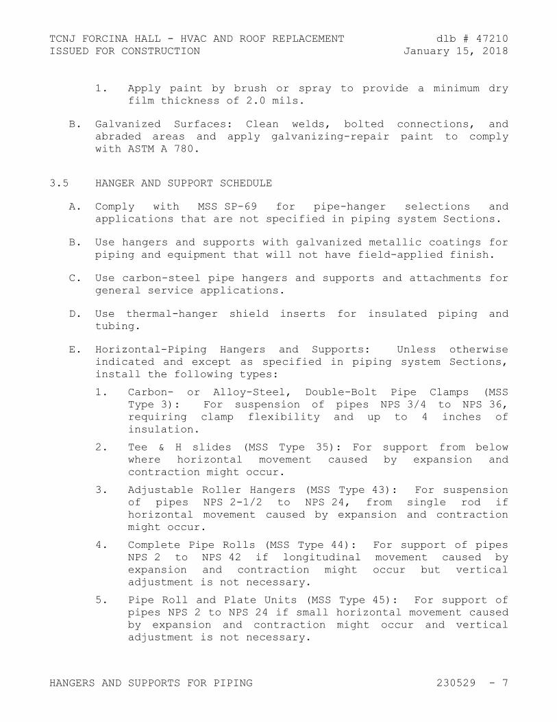
TCNJ FORCINA HALL - HVAC AND ROOF REPLACEMENT dlb # 47210
ISSUED FOR CONSTRUCTION January 15, 2018
HANGERS AND SUPPORTS FOR PIPING 230529 - 7
1. Apply paint by brush or spray to provide a minimum dry
film thickness of 2.0 mils.
B. Galvanized Surfaces: Clean welds, bolted connections, and
abraded areas and apply galvanizing-repair paint to comply
with ASTM A 780.
3.5 HANGER AND SUPPORT SCHEDULE
A. Comply with MSS SP-69 for pipe-hanger selections and
applications that are not specified in piping system Sections.
B. Use hangers and supports with galvanized metallic coatings for
piping and equipment that will not have field-applied finish.
C. Use carbon-steel pipe hangers and supports and attachments for
general service applications.
D. Use thermal-hanger shield inserts for insulated piping and
tubing.
E. Horizontal-Piping Hangers and Supports: Unless otherwise
indicated and except as specified in piping system Sections,
install the following types:
1. Carbon- or Alloy-Steel, Double-Bolt Pipe Clamps (MSS
Type 3): For suspension of pipes NPS 3/4 to NPS 36,
requiring clamp flexibility and up to 4 inches of
insulation.
2. Tee & H slides (MSS Type 35): For support from below
where horizontal movement caused by expansion and
contraction might occur.
3. Adjustable Roller Hangers (MSS Type 43): For suspension
of pipes NPS 2-1/2 to NPS 24, from single rod if
horizontal movement caused by expansion and contraction
might occur.
4. Complete Pipe Rolls (MSS Type 44): For support of pipes
NPS 2 to NPS 42 if longitudinal movement caused by
expansion and contraction might occur but vertical
adjustment is not necessary.
5. Pipe Roll and Plate Units (MSS Type 45): For support of
pipes NPS 2 to NPS 24 if small horizontal movement caused
by expansion and contraction might occur and vertical
adjustment is not necessary.

TCNJ FORCINA HALL - HVAC AND ROOF REPLACEMENT dlb # 47210
ISSUED FOR CONSTRUCTION January 15, 2018
HANGERS AND SUPPORTS FOR PIPING 230529 - 8
6. Adjustable Pipe Roll and Base Units (MSS Type 46): For
support of pipes NPS 2 to NPS 30 if vertical and lateral
adjustment during installation might be required in
addition to expansion and contraction.
F. Vertical-Piping Clamps: Unless otherwise indicated and except
as specified in piping system Sections, install the following
types:
1. Extension Pipe or Riser Clamps (MSS Type 8): For support
of pipe risers NPS 3/4 to NPS 24.
2. Carbon- or Alloy-Steel Riser Clamps (MSS Type 42): For
support of pipe risers NPS 3/4 to NPS 24 if longer ends
are required for riser clamps.
G. Hanger-Rod Attachments: Unless otherwise indicated and except
as specified in piping system Sections, install the following
types:
1. Steel Turnbuckles (MSS Type 13): For adjustment up to 6
inches for heavy loads.
2. Steel Clevises (MSS Type 14): For 120 to 450 deg F
piping installations.
3. Steel Weldless Eye Nuts (MSS Type 17): For 120 to 450
deg F piping installations.
H. Building Attachments: Unless otherwise indicated and except
as specified in piping system Sections, install the following
types:
1. Center-Beam Clamps (MSS Type 21): For attaching to
center of bottom flange of beams.
2. Welded Beam Attachments (MSS Type 22): For attaching to
bottom of beams if loads are considerable and rod sizes
are large.
3. Welded-Steel Brackets: For support of pipes from below
or for suspending from above by using clip and rod. Use
one of the following for indicated loads:
a. Light (MSS Type 31): 750 lb.
b. Medium (MSS Type 32): 1500 lb.
c. Heavy (MSS Type 33): 3000 lb.
4. Plate Lugs (MSS Type 57): For attaching to steel beams
if flexibility at beam is required.
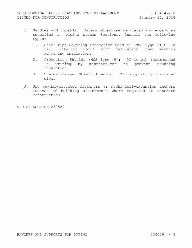
TCNJ FORCINA HALL - HVAC AND ROOF REPLACEMENT dlb # 47210
ISSUED FOR CONSTRUCTION January 15, 2018
HANGERS AND SUPPORTS FOR PIPING 230529 - 9
I. Saddles and Shields: Unless otherwise indicated and except as
specified in piping system Sections, install the following
types:
1. Steel-Pipe-Covering Protection Saddles (MSS Type 39): To
fill interior voids with insulation that matches
adjoining insulation.
2. Protection Shields (MSS Type 40): Of length recommended
in writing by manufacturer to prevent crushing
insulation.
3. Thermal-Hanger Shield Inserts: For supporting insulated
pipe.
J. Use powder-actuated fasteners or mechanical-expansion anchors
instead of building attachments where required in concrete
construction.
END OF SECTION 230529

TCNJ FORCINA HALL - HVAC AND ROOF REPLACEMENT dlb # 47210
ISSUED FOR CONSTRUCTION January 15, 2018

TCNJ FORCINA HALL - HVAC AND ROOF REPLACEMENT dlb # 47210
ISSUED FOR CONSTRUCTION January 15, 2018
HEAT TRACING FOR HVAC PIPING 230533 - 1
SECTION 230533 - HEAT TRACING FOR HVAC PIPING
PART 1 - GENERAL
1.1 RELATED DOCUMENTS
A. Drawings and general provisions of the Contract, including
General and Supplementary Conditions and Division 01
Specification Sections, apply to this Section.
1.2 SUMMARY
A. Section includes heat tracing for HVAC piping with the
following electric heating cables:
1. Self-regulating, parallel resistance.
1.3 ACTION SUBMITTALS
A. Product Data: For each type of product.
1. Include rated capacities, operating characteristics, and
furnished specialties and accessories.
2. Schedule heating capacity, length of cable, spacing, and
electrical power requirement for each electric heating
cable required.
B. Shop Drawings: For electric heating cable.
1. Include plans, elevations, sections, and attachment
details.
2. Include diagrams for power, signal, and control wiring.
1.4 INFORMATIONAL SUBMITTALS
A. Field quality-control reports.
B. Sample Warranty: For special warranty.
1.5 CLOSEOUT SUBMITTALS
A. Operation and Maintenance Data: For electric heating cables
to include in operation and maintenance manuals.

TCNJ FORCINA HALL - HVAC AND ROOF REPLACEMENT dlb # 47210
ISSUED FOR CONSTRUCTION January 15, 2018
HEAT TRACING FOR HVAC PIPING 230533 - 2
PART 2 - PRODUCTS
2.1 SELF-REGULATING, PARALLEL-RESISTANCE HEATING CABLES
A. Basis-of-Design Product: Subject to compliance with
requirements, provide product indicated on Drawings or
comparable product by one of the following or equivalent:
1. BriskHeat.
2. Chromalox.
3. Delta-Therm Corporation.
4. Easy Heat; a division of EGS Electrical Group LLC.
5. Pyrotenax; a brand of Tyco Thermal Controls LLC.
6. Raychem; a brand of Tyco Thermal Controls LLC.
7. Thermon Americas Inc.
8. Trasor Corp.
B. Comply with IEEE 515.1.
C. Heating Element: Pair of parallel No. 16 AWG, nickel-coated,
stranded copper bus wires embedded in crosslinked conductive
polymer core, which varies heat output in response to
temperature along its length. Terminate with waterproof,
factory-assembled, nonheating leads with connectors at one
end, and seal the opposite end watertight. Cable shall be
capable of crossing over itself once without overheating.
D. Electrical Insulating Jacket: Flame-retardant polyolefin.
E. Cable Cover: Tinned-copper braid and polyolefin outer jacket.
F. Maximum Operating Temperature (Power On): 150 deg. F.
G. Maximum Exposure Temperature (Power Off): 150 deg. F.
H. Electrical Components, Devices, and Accessories: Listed and
labeled as defined in NFPA 70, by a qualified testing agency,
and marked for intended location and application.
2.2 CONTROLS
A. Corrosion-resistant, waterproof control enclosure.

TCNJ FORCINA HALL - HVAC AND ROOF REPLACEMENT dlb # 47210
ISSUED FOR CONSTRUCTION January 15, 2018
HEAT TRACING FOR HVAC PIPING 230533 - 3
2.3 ACCESSORIES
A. Cable Installation Accessories: Fiberglass tape, heat-
conductive putty, cable ties, silicone end seals and splice
kits, and installation clips all furnished by manufacturer, or
as recommended in writing by manufacturer.
B. Warning Labels: Refer to Section 230553 "Identification for
HVAC Piping and Equipment."
C. Warning Tape: Continuously printed "Electrical Tracing";
vinyl, at least 3 mils (0.08 mm) thick, and with pressure-
sensitive, permanent, waterproof, self-adhesive back.
1. Width for Markers on Pipes with OD, Including Insulation,
Less Than 6 Inches: 3/4 inch minimum.
2. Width for Markers on Pipes with OD, Including Insulation,
6 Inches or Larger: 1-1/2 inches minimum.
PART 3 - EXECUTION
3.1 EXAMINATION
A. Examine surfaces and substrates to receive electric heating
cables for compliance with requirements for installation
tolerances and other conditions affecting performance.
1. Ensure surfaces and pipes in contact with electric
heating cables are free of burrs and sharp protrusions.
B. Proceed with installation only after unsatisfactory conditions
have been corrected.
3.2 INSTALLATION
A. Install electric heating cable across expansion joints
according to manufacturer's written instructions; use slack
cable to allow movement without damage to cable.
B. Install electric heating cables after piping has been tested
and before insulation is installed.
C. Install electric heating cables according to IEEE 515.1.
D. Install insulation over piping with electric cables according
to Section 230719 "HVAC Piping Insulation."

TCNJ FORCINA HALL - HVAC AND ROOF REPLACEMENT dlb # 47210
ISSUED FOR CONSTRUCTION January 15, 2018
HEAT TRACING FOR HVAC PIPING 230533 - 4
E. Install warning tape on piping insulation where piping is
equipped with electric heating cables.
F. Set field-adjustable switches and circuit-breaker trip ranges.
3.3 CONNECTIONS
A. Ground equipment according to Section 260526 "Grounding and
Bonding for Electrical Systems."
B. Connect wiring according to Section 260519 "Low-Voltage
Electrical Power Conductors and Cables."
3.4 FIELD QUALITY CONTROL
A. Manufacturer's Field Service: Engage a factory-authorized
service representative to test and inspect components,
assemblies, and equipment installations, including
connections.
B. Perform the following tests and inspections with the
assistance of a factory-authorized service representative:
1. Perform tests after cable installation but before
application of coverings such as insulation, wall or
ceiling construction, or concrete.
2. Test cables for electrical continuity and insulation
integrity before energizing.
3. Test cables to verify rating and power input. Energize
and measure voltage and current simultaneously.
C. Repeat tests for continuity, insulation resistance, and input
power after applying thermal insulation on pipe-mounted
cables.
D. Cables will be considered defective if they do not pass tests
and inspections.
E. Prepare test and inspection reports.
3.5 PROTECTION
A. Protect installed heating cables, including nonheating leads,
from damage during construction.

TCNJ FORCINA HALL - HVAC AND ROOF REPLACEMENT dlb # 47210
ISSUED FOR CONSTRUCTION January 15, 2018
HEAT TRACING FOR HVAC PIPING 230533 - 5
B. Remove and replace damaged heat-tracing cables.
END OF SECTION 230533

TCNJ FORCINA HALL - HVAC AND ROOF REPLACEMENT dlb # 47210
ISSUED FOR CONSTRUCTION January 15, 2018

TCNJ FORCINA HALL - HVAC AND ROOF REPLACEMENT dlb # 47210
ISSUED FOR CONSTRUCTION January 15, 2018
VIBRATION CONTROLS FOR HVAC 230548 - 1
SECTION 230548 - VIBRATION CONTROLS FOR HVAC
PART 1 - GENERAL
1.1 RELATED DOCUMENTS
A. Drawings and general provisions of the Contract, including
General and Supplementary Conditions and Division 01
Specification Sections, apply to this Section.
1.2 SUMMARY
A. Section Includes:
1. Elastomeric hangers.
1.3 ACTION SUBMITTALS
A. Product Data: For each type of product.
1. Include rated load, rated deflection, and overload
capacity for each vibration isolation device.
2. Illustrate and indicate style, material, strength,
fastening provision, and finish for each type and size of
vibration isolation device type required.
PART 2 - PRODUCTS
2.1 ELASTOMERIC HANGERS
A. Elastomeric Mount in a Steel Frame with Upper and Lower Steel
Hanger Rods:
1. Manufacturers: Subject to compliance with requirements,
available manufacturers offering products that may be
incorporated into the Work include, but are not limited
to, the following:
a. Ace Mountings Co., Inc.
b. California Dynamics Corporation.
c. Isolation Technology, Inc.
d. Kinetics Noise Control, Inc.

TCNJ FORCINA HALL - HVAC AND ROOF REPLACEMENT dlb # 47210
ISSUED FOR CONSTRUCTION January 15, 2018
VIBRATION CONTROLS FOR HVAC 230548 - 2
e. Mason Industries, Inc.
f. Vibration Eliminator Co., Inc.
g. Vibration Mountings & Controls, Inc.
2. Frame: Steel, fabricated with a connection for an upper
threaded hanger rod and an opening on the underside to
allow for a maximum of 30 degrees of angular lower
hanger-rod misalignment without binding or reducing
isolation efficiency.
3. Dampening Element: Molded, oil-resistant rubber,
neoprene, or other elastomeric material with a projecting
bushing for the underside opening preventing steel to
steel contact.
PART 3 - EXECUTION
3.1 EXAMINATION
A. Examine areas and equipment to receive vibration isolation
control devices for compliance with requirements for
installation tolerances and other conditions affecting
performance of the Work.
B. Examine roughing-in of reinforcement and cast-in-place anchors
to verify actual locations before installation.
C. Proceed with installation only after unsatisfactory conditions
have been corrected.
3.2 VIBRATION CONTROL DEVICE INSTALLATION
A. Installation of vibration isolators must not cause any change
of position of equipment, piping, or ductwork resulting in
stresses or misalignment.
END OF SECTION 230548.13

TCNJ FORCINA HALL - HVAC AND ROOF REPLACEMENT dlb # 47210
ISSUED FOR CONSTRUCTION January 15, 2018
IDENTIFICATION FOR HVAC PIPING AND EQUIPMENT 230553 - 1
SECTION 230553 - IDENTIFICATION FOR HVAC PIPING AND EQUIPMENT
PART 1 - GENERAL
1.1 RELATED DOCUMENTS
A. Drawings and general provisions of the Contract, including
General and Supplementary Conditions and Division 01
Specification Sections, apply to this Section.
1.2 SUMMARY
A. Section Includes:
1. Equipment labels.
2. Warning signs and labels.
3. Pipe labels.
4. Duct labels.
5. Stencils.
6. Valve tags.
7. Warning tags.
1.3 ACTION SUBMITTALS
A. Product Data: For each type of product.
B. Samples: For color, letter style, and graphic representation
required for each identification material and device.
C. Equipment Label Schedule: Include a listing of all equipment
to be labeled with the proposed content for each label.
D. Valve numbering scheme.
E. Valve Schedules: For each piping system to include in
maintenance manuals.

TCNJ FORCINA HALL - HVAC AND ROOF REPLACEMENT dlb # 47210
ISSUED FOR CONSTRUCTION January 15, 2018
IDENTIFICATION FOR HVAC PIPING AND EQUIPMENT 230553 - 2
PART 2 - PRODUCTS
2.1 EQUIPMENT LABELS
A. Metal Labels for Equipment:
1. Material and Thickness: anodized aluminum, 0.032-inch
minimum thickness, and having predrilled or stamped holes
for attachment hardware.
2. Letter Color: White.
3. Background Color: Black.
4. Minimum Label Size: Length and width vary for required
label content, but not less than 2-1/2 by 3/4 inch.
5. Minimum Letter Size: 1/4 inch for name of units if
viewing distance is less than 24 inches, 1/2 inch for
viewing distances up to 72 inches, and proportionately
larger lettering for greater viewing distances. Include
secondary lettering two-thirds to three-quarters the size
of principal lettering.
6. Fasteners: Stainless-steel rivets or self-tapping screws.
7. Adhesive: Contact-type permanent adhesive, compatible
with label and with substrate.
B. Label Content: Include equipment's Drawing designation or
unique equipment number, Drawing numbers where equipment is
indicated (plans, details, and schedules), and the
Specification Section number and title where equipment is
specified.
C. Equipment Label Schedule: For each item of equipment to be
labeled, on 8-1/2-by-11-inch bond paper. Tabulate equipment
identification number, and identify Drawing numbers where
equipment is indicated (plans, details, and schedules) and the
Specification Section number and title where equipment is
specified. Equipment schedule shall be included in operation
and maintenance data.
2.2 WARNING SIGNS AND LABELS
A. Material and Thickness: Multilayer, multicolor, plastic labels
for mechanical engraving, 1/8 inch thick, and having
predrilled holes for attachment hardware.

TCNJ FORCINA HALL - HVAC AND ROOF REPLACEMENT dlb # 47210
ISSUED FOR CONSTRUCTION January 15, 2018
IDENTIFICATION FOR HVAC PIPING AND EQUIPMENT 230553 - 3
B. Letter Color: White.
C. Background Color: Red.
D. Maximum Temperature: Able to withstand temperatures up to 160
deg F.
E. Minimum Label Size: Length and width vary for required label
content, but not less than 2-1/2 by 3/4 inch.
F. Minimum Letter Size: 1/4 inch for name of units if viewing
distance is less than 24 inches, 1/2 inch for viewing
distances up to 72 inches, and proportionately larger
lettering for greater viewing distances. Include secondary
lettering two-thirds to three-quarters the size of principal
lettering.
G. Fasteners: Stainless-steel rivets or self-tapping screws.
H. Adhesive: Contact-type permanent adhesive, compatible with
label and with substrate.
I. Label Content: Include caution and warning information plus
emergency notification instructions.
2.3 PIPE LABELS
A. General Requirements for Manufactured Pipe Labels: Preprinted,
color-coded, with lettering indicating service, and showing
flow direction according to ASME A13.1.
B. Pre-tensioned Pipe Labels: Pre-coiled, semi-rigid plastic
formed to cover full circumference of pipe and to attach to
pipe without fasteners or adhesive.
C. Pipe Label Contents: Include identification of piping service
using same designations or abbreviations as used on Drawings;
also include pipe size and an arrow indicating flow direction.
1. Flow-Direction Arrows: Integral with piping system
service lettering to accommodate both directions or as
separate unit on each pipe label to indicate flow
direction.
2. Lettering Size: At least 1/2 inch for viewing distances
up to 72 inches and proportionately larger lettering for
greater viewing distances.

TCNJ FORCINA HALL - HVAC AND ROOF REPLACEMENT dlb # 47210
ISSUED FOR CONSTRUCTION January 15, 2018
IDENTIFICATION FOR HVAC PIPING AND EQUIPMENT 230553 - 4
2.4 DUCT LABELS
A. Material and Thickness: Self-adhesive, vinyl labels printed
with UV resistant eco-solvent ink, reinforced with UV,
chemical, abrasion, and moisture resistant laminate layer.
Suitable for indoor and outdoor industrial environments.
B. Letter Color: White.
C. Background Color: Blue.
D. Service Temperature range: -40 F to +176 F.
E. Minimum Label Size: Length and width vary for required label
content, but not less than 2-1/2 by 3/4 inch.
F. Minimum Letter Size: 1/4 inch for name of units if viewing
distance is less than 24 inches, 1/2 inch for viewing
distances up to 72 inches, and proportionately larger
lettering for greater viewing distances. Include secondary
lettering two-thirds to three-quarters the size of principal
lettering.
G. Duct Label Contents: Include identification of duct service
using same designations or abbreviations as used on Drawings;
also include an arrow indicating flow direction.
1. Flow-Direction Arrows: Integral with duct system service
lettering to accommodate both directions or as separate
unit on each duct label to indicate flow direction.
2.5 VALVE TAGS
A. Description: Stamped or engraved with 1/4-inch letters for
piping system abbreviation and 1/2-inch numbers.
1. Tag Material: Brass, 0.032-inch minimum thickness, and
having predrilled or stamped holes for attachment
hardware.
2. Fasteners: Brass beaded chain.
B. Valve Schedules: For each piping system, on 8-1/2-by-11-inch
bond paper. Tabulate valve number, piping system, system
abbreviation (as shown on valve tag), location of valve (room
or space), normal-operating position (open, closed, or
modulating), and variations for identification. Mark valves
for emergency shutoff and similar special uses.

TCNJ FORCINA HALL - HVAC AND ROOF REPLACEMENT dlb # 47210
ISSUED FOR CONSTRUCTION January 15, 2018
IDENTIFICATION FOR HVAC PIPING AND EQUIPMENT 230553 - 5
1. Valve-tag schedule shall be included in operation and
maintenance data.
PART 3 - EXECUTION
3.1 PREPARATION
A. Clean piping and equipment surfaces of substances that could
impair bond of identification devices, including dirt, oil,
grease, release agents, and incompatible primers, paints, and
encapsulants.
3.2 GENERAL INSTALLATION REQUIREMENTS
A. Coordinate installation of identifying devices with completion
of covering and painting of surfaces where devices are to be
applied.
B. Coordinate installation of identifying devices with locations
of access panels and doors.
C. Install identifying devices before installing acoustical
ceilings and similar concealment.
3.3 EQUIPMENT LABEL INSTALLATION
A. Install or permanently fasten labels on each major item of
mechanical equipment.
B. Locate equipment labels where accessible and visible.
3.4 PIPE LABEL INSTALLATION
A. Pipe Label Locations: Locate pipe labels where piping is
exposed or above accessible ceilings in finished spaces;
machine rooms; accessible maintenance spaces such as shafts,
tunnels, and plenums; and exterior exposed locations as
follows:
1. Near each valve and control device.
2. Near each branch connection, excluding short takeoffs for
fixtures and terminal units. Where flow pattern is not
obvious, mark each pipe at branch.
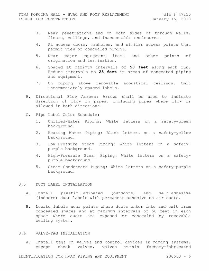
TCNJ FORCINA HALL - HVAC AND ROOF REPLACEMENT dlb # 47210
ISSUED FOR CONSTRUCTION January 15, 2018
IDENTIFICATION FOR HVAC PIPING AND EQUIPMENT 230553 - 6
3. Near penetrations and on both sides of through walls,
floors, ceilings, and inaccessible enclosures.
4. At access doors, manholes, and similar access points that
permit view of concealed piping.
5. Near major equipment items and other points of
origination and termination.
6. Spaced at maximum intervals of 50 feet along each run.
Reduce intervals to 25 feet in areas of congested piping
and equipment.
7. On piping above removable acoustical ceilings. Omit
intermediately spaced labels.
B. Directional Flow Arrows: Arrows shall be used to indicate
direction of flow in pipes, including pipes where flow is
allowed in both directions.
C. Pipe Label Color Schedule:
1. Chilled-Water Piping: White letters on a safety-green
background.
2. Heating Water Piping: Black letters on a safety-yellow
background.
3. Low-Pressure Steam Piping: White letters on a safety-
purple background.
4. High-Pressure Steam Piping: White letters on a safety-
purple background.
5. Steam Condensate Piping: White letters on a safety-purple
background.
3.5 DUCT LABEL INSTALLATION
A. Install plastic-laminated (outdoors) and self-adhesive
(indoors) duct labels with permanent adhesive on air ducts.
B. Locate labels near points where ducts enter into and exit from
concealed spaces and at maximum intervals of 50 feet in each
space where ducts are exposed or concealed by removable
ceiling system.
3.6 VALVE-TAG INSTALLATION
A. Install tags on valves and control devices in piping systems,
except check valves, valves within factory-fabricated

TCNJ FORCINA HALL - HVAC AND ROOF REPLACEMENT dlb # 47210
ISSUED FOR CONSTRUCTION January 15, 2018
IDENTIFICATION FOR HVAC PIPING AND EQUIPMENT 230553 - 7
equipment units, shutoff valves, faucets, convenience and
lawn-watering hose connections, and HVAC terminal devices and
similar roughing-in connections of end-use fixtures and units.
List tagged valves in a valve schedule.
B. Valve-Tag Application Schedule: Tag valves according to size,
shape, and color scheme and with captions similar to those
indicated in the following subparagraphs:
1. Valve-Tag Size and Shape:
a. Chilled Water: 1-1/2 inches round.
b. Hot Water: 1-1/2 inches round.
c. Low-Pressure Steam: 1-1/2 inches round.
d. High-Pressure Steam: 1-1/2 inches round.
e. Steam Condensate: 1-1/2 inches round.
3.7 WARNING-TAG INSTALLATION
A. Write required message on, and attach warning tags to,
equipment and other items where required.
1. Systems requiring warning tags:
a. Heat traced piping.
END OF SECTION 230553

TCNJ FORCINA HALL - HVAC AND ROOF REPLACEMENT dlb # 47210
ISSUED FOR CONSTRUCTION January 15, 2018

TCNJ FORCINA HALL - HVAC AND ROOF REPLACEMENT dlb # 47210
ISSUED FOR CONSTRUCTION January 15, 2018
TESTING, ADJUSTING, AND BALANCING FOR HVAC 230593 - 1
SECTION 230593 - TESTING, ADJUSTING, AND BALANCING FOR HVAC
PART 1 - GENERAL
1.1 RELATED DOCUMENTS
A. Drawings and general provisions of the Contract, including
General and Supplementary Conditions and Division 01
Specification Sections, apply to this Section.
1.2 SUMMARY
A. Section Includes:
1. Pre-construction flow measurement.
2. Balancing Air Systems:
a. Constant-volume air systems.
b. Variable-air-volume systems.
3. Balancing Hydronic Piping Systems:
a. Variable-flow hydronic systems.
1.3 DEFINITIONS
A. AABC: Associated Air Balance Council.
B. NEBB: National Environmental Balancing Bureau.
C. TAB: Testing, adjusting, and balancing.
D. TABB: Testing, Adjusting, and Balancing Bureau.
E. TAB Specialist: An entity engaged to perform TAB Work.
1.4 INFORMATIONAL SUBMITTALS
A. Qualification Data: Within 15 days of Contractor's Notice to
Proceed, submit documentation that the TAB contractor and this
Project's TAB team members meet the qualifications specified
in "Quality Assurance" Article.

TCNJ FORCINA HALL - HVAC AND ROOF REPLACEMENT dlb # 47210
ISSUED FOR CONSTRUCTION January 15, 2018
TESTING, ADJUSTING, AND BALANCING FOR HVAC 230593 - 2
B. Contract Documents Examination Report: Within 15 days of
Contractor's Notice to Proceed, submit the Contract Documents
review report as specified in Part 3.
C. Strategies and Procedures Plan: Within 30 days of
Contractor's Notice to Proceed, submit TAB strategies and
step-by-step procedures as specified in "Preparation" Article.
D. Certified TAB reports.
E. Sample report forms.
F. Instrument calibration reports, to include the following:
1. Instrument type and make.
2. Serial number.
3. Application.
4. Dates of use.
5. Dates of calibration.
1.5 QUALITY ASSURANCE
A. TAB Contractor Qualifications: Engage a TAB entity certified
by AABC NEBB or TABB.
1. TAB Field Supervisor: Employee of the TAB contractor and
certified by AABC NEBB or TABB
B. Certify TAB field data reports and perform the following:
1. Review field data reports to validate accuracy of data
and to prepare certified TAB reports.
2. Certify that the TAB team complied with the approved TAB
plan and the procedures specified and referenced in this
Specification.
C. TAB Report Forms: Use standard TAB contractor's forms
approved by Architect.
D. Instrumentation Type, Quantity, Accuracy, and Calibration: As
described in ASHRAE 111, Section 5, "Instrumentation."

TCNJ FORCINA HALL - HVAC AND ROOF REPLACEMENT dlb # 47210
ISSUED FOR CONSTRUCTION January 15, 2018
TESTING, ADJUSTING, AND BALANCING FOR HVAC 230593 - 3
1.6 PROJECT CONDITIONS
A. Full Owner Occupancy: Owner will occupy the site and existing
building during entire TAB period. Cooperate with Owner
during TAB operations to minimize conflicts with Owner's
operations.
1.7 COORDINATION
A. Notice: Provide seven days' advance notice for each test.
Include scheduled test dates and times.
B. Perform TAB after leakage and pressure tests on air and water
distribution systems have been satisfactorily completed.
PART 2 - PRODUCTS (Not Applicable)
PART 3 - EXECUTION
3.1 EXAMINATION
1. Existing Air Handling Unit and Return Fan:
a. Measure and record all data as outlined in
paragraphs 3.16E, 3.16F, 3.16G.
2. Existing Exhaust Fan Systems:
a. Measure and record fan data as outlined in paragraph
3.16G.
3. Existing induction unit terminal units:
a. Measure and record fan data as outlined in paragraph
3.16I.
4. Air Outlets and Inlets:
a. Measure and record airflow at each supply, return
and exhaust diffuser, register, grille, etc.
5. Existing Hot Water and Chilled Water Pumps:
a. Measure and record pump data as outlined in
paragraph 3.16K.
b.

TCNJ FORCINA HALL - HVAC AND ROOF REPLACEMENT dlb # 47210
ISSUED FOR CONSTRUCTION January 15, 2018
TESTING, ADJUSTING, AND BALANCING FOR HVAC 230593 - 4
B. Examine the Contract Documents to become familiar with Project
requirements and to discover conditions in systems' designs
that may preclude proper TAB of systems and equipment.
C. Examine systems for installed balancing devices, such as test
ports, gage cocks, thermometer wells, flow-control devices,
balancing valves and fittings, and manual volume dampers.
Verify that locations of these balancing devices are
accessible.
D. Examine the approved submittals for HVAC systems and
equipment.
E. Examine design data including HVAC system descriptions,
statements of design assumptions for environmental conditions
and systems' output, and statements of philosophies and
assumptions about HVAC system and equipment controls.
F. Examine ceiling plenums and underfloor air plenums used for
supply, return, or relief air to verify that they meet the
leakage class of connected ducts as specified in
Section 233113 "Metal Ducts" and are properly separated from
adjacent areas. Verify that penetrations in plenum walls are
sealed and fire-stopped if required.
G. Examine equipment performance data including fan and pump
curves.
1. Relate performance data to Project conditions and
requirements, including system effects that can create
undesired or unpredicted conditions that cause reduced
capacities in all or part of a system.
2. Calculate system-effect factors to reduce performance
ratings of HVAC equipment when installed under conditions
different from the conditions used to rate equipment
performance. To calculate system effects for air
systems, use tables and charts found in AMCA 201, "Fans
and Systems," or in SMACNA's "HVAC Systems - Duct
Design." Compare results with the design data and
installed conditions.
H. Examine system and equipment installations and verify that
field quality-control testing, cleaning, and adjusting
specified in individual Sections have been performed.
I. Examine test reports specified in individual system and
equipment Sections.

TCNJ FORCINA HALL - HVAC AND ROOF REPLACEMENT dlb # 47210
ISSUED FOR CONSTRUCTION January 15, 2018
TESTING, ADJUSTING, AND BALANCING FOR HVAC 230593 - 5
J. Examine HVAC equipment and filters and verify that bearings
are greased, belts are aligned and tight, and equipment with
functioning controls is ready for operation.
K. Examine terminal units, such as variable-air-volume boxes, and
verify that they are accessible and their controls are
connected and functioning.
L. Examine strainers. Verify that startup screens are replaced
by permanent screens with indicated perforations.
M. Examine three-way valves for proper installation for their
intended function of diverting or mixing fluid flows.
N. Examine heat-transfer coils for correct piping connections and
for clean and straight fins.
O. Examine system pumps to ensure absence of entrained air in the
suction piping.
P. Examine operating safety interlocks and controls on HVAC
equipment.
Q. Report deficiencies discovered before and during performance
of TAB procedures. Observe and record system reactions to
changes in conditions. Record default set points if different
from indicated values.
3.2 PREPARATION
A. Prepare a TAB plan that includes strategies and step-by-step
procedures.
B. Complete system-readiness checks and prepare reports. Verify
the following:
1. Permanent electrical-power wiring is complete.
2. Hydronic systems are filled, clean, and free of air.
3. Automatic temperature-control systems are operational.
4. Equipment and duct access doors are securely closed.
5. Balance, smoke, and fire dampers are open.
6. Isolating and balancing valves are open and control
valves are operational.

TCNJ FORCINA HALL - HVAC AND ROOF REPLACEMENT dlb # 47210
ISSUED FOR CONSTRUCTION January 15, 2018
TESTING, ADJUSTING, AND BALANCING FOR HVAC 230593 - 6
7. Ceilings are installed in critical areas where air-
pattern adjustments are required and access to balancing
devices is provided.
8. Windows and doors can be closed so indicated conditions
for system operations can be met.
3.3 GENERAL PROCEDURES FOR TESTING AND BALANCING
A. Perform testing and balancing procedures on each system
according to the procedures contained in ASHRAE 111, SMACNA's
"HVAC Systems - Testing, Adjusting, and Balancing"] and in
this Section.
B. Cut insulation, ducts, pipes, and equipment cabinets for
installation of test probes to the minimum extent necessary
for TAB procedures.
1. After testing and balancing, patch probe holes in ducts
with same material and thickness as used to construct
ducts.
2. After testing and balancing, install test ports and duct
access doors that comply with requirements in
Section 233300 "Air Duct Accessories."
3. Install and join new insulation that matches removed
materials. Restore insulation, coverings, vapor barrier,
and finish according to Section 230713 "Duct Insulation,"
Section 230716 "HVAC Equipment Insulation," and
Section 230719 "HVAC Piping Insulation."
C. Mark equipment and balancing devices, including damper-control
positions, valve position indicators, fan-speed-control
levers, and similar controls and devices, with paint or other
suitable, permanent identification material to show final
settings.
D. Take and report testing and balancing measurements in inch-
pound (IP) units.
3.4 GENERAL PROCEDURES FOR BALANCING AIR SYSTEMS
A. Prepare test reports for both fans and outlets. Obtain
manufacturer's outlet factors and recommended testing
procedures. Crosscheck the summation of required outlet
volumes with required fan volumes.

TCNJ FORCINA HALL - HVAC AND ROOF REPLACEMENT dlb # 47210
ISSUED FOR CONSTRUCTION January 15, 2018
TESTING, ADJUSTING, AND BALANCING FOR HVAC 230593 - 7
B. Prepare schematic diagrams of systems' "as-built" duct
layouts.
C. For variable-air-volume systems, develop a plan to simulate
diversity.
D. Determine the best locations in main and branch ducts for
accurate duct-airflow measurements.
E. Check airflow patterns from the outdoor-air louvers and
dampers and the return- and exhaust-air dampers through the
supply-fan discharge and mixing dampers.
F. Locate start-stop and disconnect switches, electrical
interlocks, and motor starters.
G. Verify that motor starters are equipped with properly sized
thermal protection.
H. Check dampers for proper position to achieve desired airflow
path.
I. Check for airflow blockages.
J. Check condensate drains for proper connections and
functioning.
K. Check for proper sealing of air-handling-unit components.
L. Verify that air duct system is sealed as specified in
Section 233113 "Metal Ducts."
3.5 PROCEDURES FOR CONSTANT-VOLUME AIR SYSTEMS
A. Adjust fans to deliver total indicated airflows within the
maximum allowable fan speed listed by fan manufacturer.
1. Measure total airflow.
a. Where sufficient space in ducts is unavailable for
Pitot-tube traverse measurements, measure airflow at
terminal outlets and inlets and calculate the total
airflow.
2. Measure fan static pressures as follows to determine
actual static pressure:
a. Measure outlet static pressure as far downstream
from the fan as practical and upstream from

TCNJ FORCINA HALL - HVAC AND ROOF REPLACEMENT dlb # 47210
ISSUED FOR CONSTRUCTION January 15, 2018
TESTING, ADJUSTING, AND BALANCING FOR HVAC 230593 - 8
restrictions in ducts such as elbows and
transitions.
b. Measure static pressure directly at the fan outlet
or through the flexible connection.
c. Measure inlet static pressure of single-inlet fans
in the inlet duct as near the fan as possible,
upstream from the flexible connection, and
downstream from duct restrictions.
d. Measure inlet static pressure of double-inlet fans
through the wall of the plenum that houses the fan.
3. Measure static pressure across each component that makes
up an air-handling unit, rooftop unit, and other air-
handling and -treating equipment.
a. Report the cleanliness status of filters and the
time static pressures are measured.
4. Measure static pressures entering and leaving other
devices, such as sound traps, heat-recovery equipment,
and air washers, under final balanced conditions.
5. Review Record Documents to determine variations in design
static pressures versus actual static pressures.
Calculate actual system-effect factors. Recommend
adjustments to accommodate actual conditions.
6. Obtain approval from Architect for adjustment of fan
speed higher or lower than indicated speed. Comply with
requirements in HVAC Sections for air-handling units for
adjustment of fans, belts, and pulley sizes to achieve
indicated air-handling-unit performance.
7. Do not make fan-speed adjustments that result in motor
overload. Consult equipment manufacturers about fan-
speed safety factors. Modulate dampers and measure fan-
motor amperage to ensure that no overload will occur.
Measure amperage in full-cooling, full-heating,
economizer, and any other operating mode to determine the
maximum required brake horsepower.
B. Adjust volume dampers for main duct, submain ducts, and major
branch ducts to indicated airflows within specified
tolerances.
1. Measure airflow of submain and branch ducts.
a. Where sufficient space in submain and branch ducts
is unavailable for Pitot-tube traverse measurements,

TCNJ FORCINA HALL - HVAC AND ROOF REPLACEMENT dlb # 47210
ISSUED FOR CONSTRUCTION January 15, 2018
TESTING, ADJUSTING, AND BALANCING FOR HVAC 230593 - 9
measure airflow at terminal outlets and inlets and
calculate the total airflow for that zone.
2. Measure static pressure at a point downstream from the
balancing damper, and adjust volume dampers until the
proper static pressure is achieved.
3. Remeasure each submain and branch duct after all have
been adjusted. Continue to adjust submain and branch
ducts to indicated airflows within specified tolerances.
C. Measure air outlets and inlets without making adjustments.
1. Measure terminal outlets using a direct-reading hood or
outlet manufacturer's written instructions and
calculating factors.
D. Adjust air outlets and inlets for each space to indicated
airflows within specified tolerances of indicated values.
Make adjustments using branch volume dampers rather than
extractors and the dampers at air terminals.
1. Adjust each outlet in same room or space to within
specified tolerances of indicated quantities without
generating noise levels above the limitations prescribed
by the Contract Documents.
2. Adjust patterns of adjustable outlets for proper
distribution without drafts.
3.6 PROCEDURES FOR VARIABLE-AIR-VOLUME SYSTEMS
A. Compensating for Diversity: When the total airflow of all
terminal units is more than the indicated airflow of the fan,
place a selected number of terminal units at a minimum set-
point airflow with the remainder at maximum-airflow condition
until the total airflow of the terminal units equals the
indicated airflow of the fan. Select the reduced-airflow
terminal units so they are distributed evenly among the branch
ducts.
B. Pressure-Independent, Variable-Air-Volume Systems: After the
fan systems have been adjusted, adjust the variable-air-volume
systems as follows:
1. Set outdoor-air dampers at minimum, and set return- and
exhaust-air dampers at a position that simulates full-
cooling load.

TCNJ FORCINA HALL - HVAC AND ROOF REPLACEMENT dlb # 47210
ISSUED FOR CONSTRUCTION January 15, 2018
TESTING, ADJUSTING, AND BALANCING FOR HVAC 230593 - 10
2. Select the terminal unit that is most critical to the
supply-fan airflow and static pressure. Measure static
pressure. Adjust system static pressure so the entering
static pressure for the critical terminal unit is not
less than the sum of the terminal-unit manufacturer's
recommended minimum inlet static pressure plus the static
pressure needed to overcome terminal-unit discharge
system losses.
3. Measure total system airflow. Adjust to within indicated
airflow.
4. Set terminal units at maximum airflow and adjust
controller or regulator to deliver the designed maximum
airflow. Use terminal-unit manufacturer's written
instructions to make this adjustment. When total airflow
is correct, balance the air outlets downstream from
terminal units the same as described for constant-volume
air systems.
5. Set terminal units at minimum airflow and adjust
controller or regulator to deliver the designed minimum
airflow. Check air outlets for a proportional reduction
in airflow the same as described for constant-volume air
systems.
a. If air outlets are out of balance at minimum
airflow, report the condition but leave outlets
balanced for maximum airflow.
6. Remeasure the return airflow to the fan while operating
at maximum return airflow and minimum outdoor airflow.
a. Adjust the fan and balance the return-air ducts and
inlets the same as described for constant-volume air
systems.
7. Measure static pressure at the most critical terminal
unit and adjust the static-pressure controller at the
main supply-air sensing station to ensure that adequate
static pressure is maintained at the most critical unit.
8. Record final fan-performance data.
C. For induction type VAV terminal units:
1. Adjust return air damper linkages such that return air
damper is closed when primary air damper is at full
cooling position.

TCNJ FORCINA HALL - HVAC AND ROOF REPLACEMENT dlb # 47210
ISSUED FOR CONSTRUCTION January 15, 2018
TESTING, ADJUSTING, AND BALANCING FOR HVAC 230593 - 11
2. Adjust return air linkage such that the total unit
airflow remains constant when primary damper modulates
down to minimum open position.
3.7 GENERAL PROCEDURES FOR HYDRONIC SYSTEMS
A. Prepare test reports with pertinent design data, and number in
sequence starting at pump to end of system. Check the sum of
branch-circuit flows against the approved pump flow rate.
Correct variations that exceed plus or minus 5 percent.
B. Prepare schematic diagrams of systems' "as-built" piping
layouts.
C. Prepare hydronic systems for testing and balancing according
to the following, in addition to the general preparation
procedures specified above:
1. Open all manual valves for maximum flow.
2. Check liquid level in expansion tank.
3. Check makeup water-station pressure gage for adequate
pressure for highest vent.
4. Check flow-control valves for specified sequence of
operation, and set at indicated flow.
5. Set differential-pressure control valves at the specified
differential pressure. Do not set at fully closed
position when pump is positive-displacement type unless
several terminal valves are kept open.
6. Set system controls so automatic valves are wide open to
heat exchangers.
7. Check pump-motor load. If motor is overloaded, throttle
main flow-balancing device so motor nameplate rating is
not exceeded.
8. Check air vents for a forceful liquid flow exiting from
vents when manually operated.
3.8 PROCEDURES FOR VARIABLE-FLOW HYDRONIC SYSTEMS
A. Balance systems with automatic two- and three-way control
valves by setting systems at maximum flow through heat-
exchange terminals and proceed as specified above for hydronic
systems.

TCNJ FORCINA HALL - HVAC AND ROOF REPLACEMENT dlb # 47210
ISSUED FOR CONSTRUCTION January 15, 2018
TESTING, ADJUSTING, AND BALANCING FOR HVAC 230593 - 12
3.9 PROCEDURES FOR STEAM SYSTEMS
A. Measure and record upstream and downstream pressure of each
piece of equipment.
B. Measure and record upstream and downstream steam pressure of
pressure-reducing valves.
C. Check settings and operation of automatic temperature-control
valves, self-contained control valves, and pressure-reducing
valves. Record final settings.
D. Check settings and operation of each safety valve. Record
settings.
E. Verify the operation of each steam trap.
3.10 PROCEDURES FOR HEAT EXCHANGERS
A. Measure water flow through all circuits.
B. Adjust water flow to within specified tolerances.
C. Measure inlet and outlet water temperatures.
D. Measure inlet steam pressure.
E. Check settings and operation of safety and relief valves.
Record settings.
3.11 PROCEDURES FOR MOTORS
A. Motors, 1/2 HP and Larger: Test at final balanced conditions
and record the following data:
1. Manufacturer's name, model number, and serial number.
2. Motor horsepower rating.
3. Motor rpm.
4. Efficiency rating.
5. Nameplate and measured voltage, each phase.
6. Nameplate and measured amperage, each phase.
7. Starter thermal-protection-element rating.

TCNJ FORCINA HALL - HVAC AND ROOF REPLACEMENT dlb # 47210
ISSUED FOR CONSTRUCTION January 15, 2018
TESTING, ADJUSTING, AND BALANCING FOR HVAC 230593 - 13
B. Motors Driven by Variable-Frequency Controllers: Test for
proper operation at speeds varying from minimum to maximum.
Test the manual bypass of the controller to prove proper
operation. Record observations including name of controller
manufacturer, model number, serial number, and nameplate data.
3.12 PROCEDURES FOR HEAT-TRANSFER COILS
A. Measure, adjust, and record the following data for each water
coil:
1. Entering- and leaving-water temperature.
2. Water flow rate.
3. Water pressure drop.
4. Dry-bulb temperature of entering and leaving air.
5. Wet-bulb temperature of entering and leaving air for
cooling coils.
6. Airflow.
7. Air pressure drop.
3.13 PROCEDURES FOR TESTING, ADJUSTING, AND BALANCING EXISTING
SYSTEMS
A. Perform a preconstruction inspection of existing equipment
that is to remain and be reused.
1. Measure and record the operating speed, airflow, and
static pressure of each fan.
2. Measure motor voltage and amperage. Compare the values
to motor nameplate information.
3. Check the condition of filters.
4. Check the condition of coils.
5. Check the operation of the drain pan and condensate-drain
trap.
6. Check bearings and other lubricated parts for proper
lubrication.
7. Report on the operating condition of the equipment and
the results of the measurements taken. Report
deficiencies.

TCNJ FORCINA HALL - HVAC AND ROOF REPLACEMENT dlb # 47210
ISSUED FOR CONSTRUCTION January 15, 2018
TESTING, ADJUSTING, AND BALANCING FOR HVAC 230593 - 14
B. Before performing testing and balancing of existing systems,
inspect existing equipment that is to remain and be reused to
verify that existing equipment has been cleaned and
refurbished. Verify the following:
1. New filters are installed.
2. Coils are clean and fins combed.
3. Drain pans are clean.
4. Fans are clean.
5. Bearings and other parts are properly lubricated.
6. Deficiencies noted in the preconstruction report are
corrected.
C. Perform testing and balancing of existing systems to the
extent that existing systems are affected by the renovation
work.
1. Compare the indicated airflow of the renovated work to
the measured fan airflows, and determine the new fan
speed and the face velocity of filters and coils.
2. Verify that the indicated airflows of the renovated work
result in filter and coil face velocities and fan speeds
that are within the acceptable limits defined by
equipment manufacturer.
3. If calculations increase or decrease the air flow rates
and water flow rates by more than 5 percent, make
equipment adjustments to achieve the calculated rates.
If increase or decrease is 5 percent or less, equipment
adjustments are not required.
4. Balance each air outlet.
3.14 TOLERANCES
A. Set HVAC system's air flow rates and water flow rates within
the following tolerances:
1. Supply, Return, and Exhaust Fans and Equipment with Fans:
Plus or minus 10 percent.
2. Air Outlets and Inlets: Plus or minus 10 percent.
3. Heating-Water Flow Rate: Plus or minus 10 percent.
4. Cooling-Water Flow Rate: Plus or minus 10 percent.

TCNJ FORCINA HALL - HVAC AND ROOF REPLACEMENT dlb # 47210
ISSUED FOR CONSTRUCTION January 15, 2018
TESTING, ADJUSTING, AND BALANCING FOR HVAC 230593 - 15
3.15 REPORTING
A. Initial Construction-Phase Report: Based on examination of
the Contract Documents as specified in "Examination" Article,
prepare a report on the adequacy of design for systems'
balancing devices. Recommend changes and additions to
systems' balancing devices to facilitate proper performance
measuring and balancing. Recommend changes and additions to
HVAC systems and general construction to allow access for
performance measuring and balancing devices.
B. Status Reports: Prepare biweekly progress reports to describe
completed procedures, procedures in progress, and scheduled
procedures. Include a list of deficiencies and problems found
in systems being tested and balanced. Prepare a separate
report for each system and each building floor for systems
serving multiple floors.
3.16 FINAL REPORT
A. General: Prepare a certified written report; tabulate and
divide the report into separate sections for tested systems
and balanced systems.
1. Include a certification sheet at the front of the
report's binder, signed and sealed by the certified
testing and balancing engineer.
2. Include a list of instruments used for procedures, along
with proof of calibration.
B. Final Report Contents: In addition to certified field-report
data, include the following:
1. Pump curves.
2. Fan curves.
3. Manufacturers' test data.
4. Field test reports prepared by system and equipment
installers.
5. Other information relative to equipment performance; do
not include Shop Drawings and product data.
C. General Report Data: In addition to form titles and entries,
include the following data:
1. Title page.

TCNJ FORCINA HALL - HVAC AND ROOF REPLACEMENT dlb # 47210
ISSUED FOR CONSTRUCTION January 15, 2018
TESTING, ADJUSTING, AND BALANCING FOR HVAC 230593 - 16
2. Name and address of the TAB contractor.
3. Project name.
4. Project location.
5. Architect's name and address.
6. Engineer's name and address.
7. Contractor's name and address.
8. Report date.
9. Signature of TAB supervisor who certifies the report.
10. Table of Contents with the total number of pages defined
for each section of the report. Number each page in the
report.
11. Summary of contents including the following:
a. Indicated versus final performance.
b. Notable characteristics of systems.
c. Description of system operation sequence if it
varies from the Contract Documents.
12. Nomenclature sheets for each item of equipment.
13. Data for terminal units, including manufacturer's name,
type, size, and fittings.
14. Notes to explain why certain final data in the body of
reports vary from indicated values.
15. Test conditions for fans and pump performance forms
including the following:
a. Settings for outdoor-, return-, and exhaust-air
dampers.
b. Conditions of filters.
c. Cooling coil, wet- and dry-bulb conditions.
d. Fan drive settings including settings and percentage
of maximum pitch diameter.
e. Settings for supply-air, static-pressure controller.
f. Other system operating conditions that affect
performance.
D. System Diagrams: Include schematic layouts of air and
hydronic distribution systems. Present each system with
single-line diagram and include the following:

TCNJ FORCINA HALL - HVAC AND ROOF REPLACEMENT dlb # 47210
ISSUED FOR CONSTRUCTION January 15, 2018
TESTING, ADJUSTING, AND BALANCING FOR HVAC 230593 - 17
1. Quantities of outdoor, supply, return, and exhaust
airflows.
2. Water and steam flow rates.
3. Duct, outlet, and inlet sizes.
4. Pipe and valve sizes and locations.
5. Terminal units.
6. Balancing stations.
7. Position of balancing devices.
E. Air-Handling-Unit Test Reports: For air-handling units with
coils, include the following:
1. Unit Data:
a. Unit identification.
b. Location.
c. Make and type.
d. Model number and unit size.
e. Manufacturer's serial number.
f. Unit arrangement and class.
g. Discharge arrangement.
h. Sheave make, size in inches, and bore.
i. Center-to-center dimensions of sheave, and amount of
adjustments in inches.
j. Number, make, and size of belts.
k. Number, type, and size of filters.
2. Motor Data:
a. Motor make, and frame type and size.
b. Horsepower and rpm.
c. Volts, phase, and hertz.
d. Full-load amperage and service factor.
e. Sheave make, size in inches, and bore.
f. Center-to-center dimensions of sheave, and amount of
adjustments in inches.
3. Test Data (Indicated and Actual Values):
a. Total air flow rate in cfm.

TCNJ FORCINA HALL - HVAC AND ROOF REPLACEMENT dlb # 47210
ISSUED FOR CONSTRUCTION January 15, 2018
TESTING, ADJUSTING, AND BALANCING FOR HVAC 230593 - 18
b. Total system static pressure in inches wg.
c. Fan rpm.
d. Discharge static pressure in inches wg.
e. Filter static-pressure differential in inches wg.
f. Preheat-coil static-pressure differential in inches
wg.
g. Cooling-coil static-pressure differential in inches
wg.
h. Outdoor airflow in cfm.
i. Return airflow in cfm.
j. Outdoor-air damper position.
k. Return-air damper position.
l. Vortex damper position.
F. Apparatus-Coil Test Reports:
1. Coil Data:
a. System identification.
b. Location.
c. Coil type.
d. Number of rows.
e. Fin spacing in fins per inch o.c.
f. Make and model number.
g. Face area in sq. ft..
h. Tube size in NPS.
i. Tube and fin materials.
j. Circuiting arrangement.
2. Test Data (Indicated and Actual Values):
a. Air flow rate in cfm.
b. Average face velocity in fpm.
c. Air pressure drop in inches wg).
d. Outdoor-air, wet- and dry-bulb temperatures in
deg F.
e. Return-air, wet- and dry-bulb temperatures in deg F.

TCNJ FORCINA HALL - HVAC AND ROOF REPLACEMENT dlb # 47210
ISSUED FOR CONSTRUCTION January 15, 2018
TESTING, ADJUSTING, AND BALANCING FOR HVAC 230593 - 19
f. Entering-air, wet- and dry-bulb temperatures in
deg F.
g. Leaving-air, wet- and dry-bulb temperatures in
deg F.
h. Water flow rate in gpm.
i. Water pressure differential in feet of head or psig.
j. Entering-water temperature in deg F.
k. Leaving-water temperature in deg F.
G. Fan Test Reports: For supply, return, and exhaust fans,
include the following:
1. Fan Data:
a. System identification.
b. Location.
c. Make and type.
d. Model number and size.
e. Manufacturer's serial number.
f. Arrangement and class.
g. Sheave make, size in inches, and bore.
h. Center-to-center dimensions of sheave, and amount of
adjustments in inches.
2. Motor Data:
a. Motor make, and frame type and size.
b. Horsepower and rpm.
c. Volts, phase, and hertz.
d. Full-load amperage and service factor.
e. Sheave make, size in inches, and bore.
f. Center-to-center dimensions of sheave, and amount of
adjustments in inches.
g. Number, make, and size of belts.
3. Test Data (Indicated and Actual Values):
a. Total airflow rate in cfm.
b. Total system static pressure in inches wg.
c. Fan rpm.
d. Discharge static pressure in inches wg.
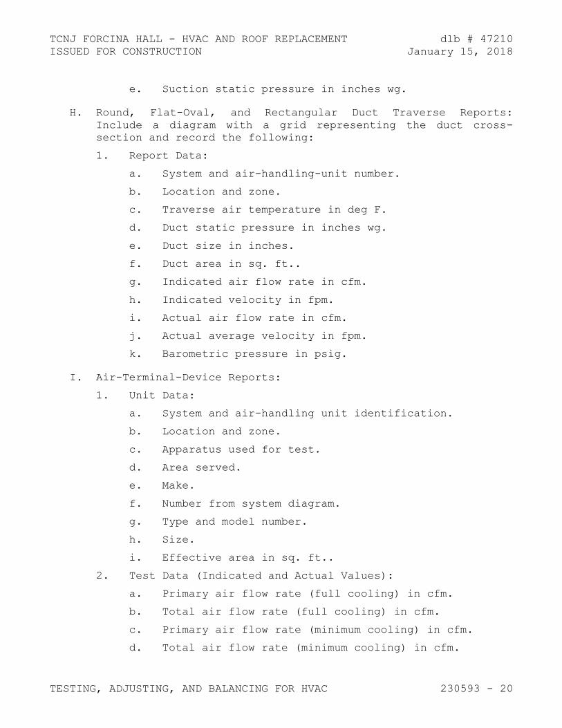
TCNJ FORCINA HALL - HVAC AND ROOF REPLACEMENT dlb # 47210
ISSUED FOR CONSTRUCTION January 15, 2018
TESTING, ADJUSTING, AND BALANCING FOR HVAC 230593 - 20
e. Suction static pressure in inches wg.
H. Round, Flat-Oval, and Rectangular Duct Traverse Reports:
Include a diagram with a grid representing the duct cross-
section and record the following:
1. Report Data:
a. System and air-handling-unit number.
b. Location and zone.
c. Traverse air temperature in deg F.
d. Duct static pressure in inches wg.
e. Duct size in inches.
f. Duct area in sq. ft..
g. Indicated air flow rate in cfm.
h. Indicated velocity in fpm.
i. Actual air flow rate in cfm.
j. Actual average velocity in fpm.
k. Barometric pressure in psig.
I. Air-Terminal-Device Reports:
1. Unit Data:
a. System and air-handling unit identification.
b. Location and zone.
c. Apparatus used for test.
d. Area served.
e. Make.
f. Number from system diagram.
g. Type and model number.
h. Size.
i. Effective area in sq. ft..
2. Test Data (Indicated and Actual Values):
a. Primary air flow rate (full cooling) in cfm.
b. Total air flow rate (full cooling) in cfm.
c. Primary air flow rate (minimum cooling) in cfm.
d. Total air flow rate (minimum cooling) in cfm.

TCNJ FORCINA HALL - HVAC AND ROOF REPLACEMENT dlb # 47210
ISSUED FOR CONSTRUCTION January 15, 2018
TESTING, ADJUSTING, AND BALANCING FOR HVAC 230593 - 21
e. Air velocity in fpm.
f. Preliminary air flow rate as needed in cfm.
g. Preliminary velocity as needed in fpm.
h. Final air flow rate in cfm.
i. Final velocity in fpm.
j. Space temperature in deg F.
J. Air Outlet and Inlet Reports: For each supply, return, and
exhaust diffuser, register and grille, include the following:
1. Airflow.
K. System-Coil Reports: For reheat coils and water coils of
terminal units, include the following:
1. Unit Data:
a. System and air-handling-unit identification.
b. Location and zone.
c. Room or riser served.
d. Coil make and size.
e. Flowmeter type.
2. Test Data (Indicated and Actual Values):
a. Air flow rate in cfm.
b. Entering-water temperature in deg F.
c. Leaving-water temperature in deg F.
d. Water pressure drop in feet of head or psig.
e. Entering-air temperature in deg F.
f. Leaving-air temperature in deg F.
L. Pump Test Reports: Calculate impeller size by plotting the
shutoff head on pump curves and include the following:
1. Unit Data:
a. Unit identification.
b. Location.
c. Service.
d. Make and size.
e. Model number and serial number.

TCNJ FORCINA HALL - HVAC AND ROOF REPLACEMENT dlb # 47210
ISSUED FOR CONSTRUCTION January 15, 2018
TESTING, ADJUSTING, AND BALANCING FOR HVAC 230593 - 22
f. Water flow rate in gpm.
g. Water pressure differential in feet of head or psig.
h. Required net positive suction head in feet of head
or psig.
i. Pump rpm.
j. Impeller diameter in inches.
k. Motor make and frame size.
l. Motor horsepower and rpm.
m. Voltage at each connection.
n. Amperage for each phase.
o. Full-load amperage and service factor.
p. Seal type.
2. Test Data (Indicated and Actual Values):
a. Static head in feet of head or psig.
b. Pump shutoff pressure in feet of head or psig.
c. Actual impeller size in inches.
d. Full-open flow rate in gpm.
e. Full-open pressure in feet of head or psig.
f. Final discharge pressure in feet of head or psig.
g. Final suction pressure in feet of head or psig.
h. Final total pressure in feet of head or psig.
i. Final water flow rate in gpm.
j. Voltage at each connection.
k. Amperage for each phase.
M. Instrument Calibration Reports:
1. Report Data:
a. Instrument type and make.
b. Serial number.
c. Application.
d. Dates of use.
e. Dates of calibration.

TCNJ FORCINA HALL - HVAC AND ROOF REPLACEMENT dlb # 47210
ISSUED FOR CONSTRUCTION January 15, 2018
TESTING, ADJUSTING, AND BALANCING FOR HVAC 230593 - 23
3.17 INSPECTIONS
A. Initial Inspection:
1. After testing and balancing are complete, operate each
system and randomly check measurements to verify that the
system is operating according to the final test and
balance readings documented in the final report.
2. Check the following for each system:
a. Measure airflow of at least 10 percent of air
outlets.
b. Measure water flow of at least 5 percent of
terminals.
c. Measure room temperature at each
thermostat/temperature sensor. Compare the reading
to the set point.
d. Verify that balancing devices are marked with final
balance position.
e. Note deviations from the Contract Documents in the
final report.
B. Final Inspection:
1. After initial inspection is complete and documentation by
random checks verifies that testing and balancing are
complete and accurately documented in the final report,
request that a final inspection be made by Architect.
2. The TAB contractor's test and balance engineer shall
conduct the inspection in the presence of Architect.
3. Architect shall randomly select measurements, documented
in the final report, to be rechecked. Rechecking shall
be limited to either 10 percent of the total measurements
recorded or the extent of measurements that can be
accomplished in a normal 8-hour business day.
4. If rechecks yield measurements that differ from the
measurements documented in the final report by more than
the tolerances allowed, the measurements shall be noted
as "FAILED."
5. If the number of "FAILED" measurements is greater than 10
percent of the total measurements checked during the
final inspection, the testing and balancing shall be
considered incomplete and shall be rejected.

TCNJ FORCINA HALL - HVAC AND ROOF REPLACEMENT dlb # 47210
ISSUED FOR CONSTRUCTION January 15, 2018
TESTING, ADJUSTING, AND BALANCING FOR HVAC 230593 - 24
C. TAB Work will be considered defective if it does not pass
final inspections. If TAB Work fails, proceed as follows:
1. Recheck all measurements and make adjustments. Revise
the final report and balancing device settings to include
all changes; resubmit the final report and request a
second final inspection.
2. If the second final inspection also fails, Owner may
contract the services of another TAB contractor to
complete TAB Work according to the Contract Documents and
deduct the cost of the services from the original TAB
contractor's final payment.
D. Prepare test and inspection reports.
3.18 ADDITIONAL TESTS
A. Within 90 days of completing TAB, perform additional TAB to
verify that balanced conditions are being maintained
throughout and to correct unusual conditions.
B. Seasonal Periods: If initial TAB procedures were not
performed during near-peak summer and winter conditions,
perform additional TAB during near-peak summer and winter
conditions.
END OF SECTION 230593

TCNJ FORCINA HALL - HVAC AND ROOF REPLACEMENT dlb # 47210
ISSUED FOR CONSTRUCTION January 15, 2018
DUCT INSULATION 230713 - 1
SECTION 230713 - DUCT INSULATION
PART 1 - GENERAL
1.1 RELATED DOCUMENTS
A. Drawings and general provisions of the Contract, including
General and Supplementary Conditions and Division 01
Specification Sections, apply to this Section.
1.2 SUMMARY
A. Section includes insulating the following duct services:
1. Indoor, concealed supply air.
2. Indoor, exposed return located in unconditioned space.
B. Related Sections:
1. Section 230716 "HVAC Equipment Insulation."
2. Section 230719 "HVAC Piping Insulation."
3. Section 233113 "Metal Ducts" for double wall insulated
ducts and duct liners.
1.3 ACTION SUBMITTALS
A. Product Data: For each type of product indicated. Include
thermal conductivity, water-vapor permeance thickness, and
jackets (both factory- and field-applied if any).
B. Shop Drawings: Include plans, elevations, sections, details,
and attachments to other work.
1. Detail application of protective shields, saddles, and
inserts at hangers for each type of insulation and
hanger.
2. Detail insulation application at elbows, fittings,
dampers, specialties and flanges for each type of
insulation.
3. Detail application of field-applied jackets.
4. Detail application at linkages of control devices.

TCNJ FORCINA HALL - HVAC AND ROOF REPLACEMENT dlb # 47210
ISSUED FOR CONSTRUCTION January 15, 2018
DUCT INSULATION 230713 - 2
1.4 INFORMATIONAL SUBMITTALS
A. Qualification Data: For qualified Installer.
B. Field quality-control reports.
1.5 QUALITY ASSURANCE
A. Installer Qualifications: Skilled mechanics who have
successfully completed an apprenticeship program or another
craft training program certified by the Department of Labor,
Bureau of Apprenticeship and Training.
1.6 DELIVERY, STORAGE, AND HANDLING
A. Packaging: Insulation material containers shall be marked by
manufacturer with appropriate ASTM standard designation, type
and grade, and maximum use temperature.
1.7 COORDINATION
A. Coordinate sizes and locations of supports, hangers, and
insulation shields specified in Section 230529 "Hangers and
Supports for HVAC Piping and Equipment."
B. Coordinate clearance requirements with duct Installer for duct
insulation application. Before preparing ductwork Shop
Drawings, establish and maintain clearance requirements for
installation of insulation and field-applied jackets and
finishes and for space required for maintenance.
1.8 SCHEDULING
A. Schedule insulation application after pressure testing systems
and, where required, after installing and testing heat
tracing. Insulation application may begin on segments that
have satisfactory test results.
B. Complete installation and concealment of plastic materials as
rapidly as possible in each area of construction.

TCNJ FORCINA HALL - HVAC AND ROOF REPLACEMENT dlb # 47210
ISSUED FOR CONSTRUCTION January 15, 2018
DUCT INSULATION 230713 - 3
PART 2 - PRODUCTS
2.1 INSULATION MATERIALS
A. Comply with requirements in "Duct Insulation Schedule,
General," "Indoor Duct and Plenum Insulation Schedule," and
"Aboveground, Outdoor Duct and Plenum Insulation Schedule"
articles for where insulating materials shall be applied.
B. Products shall not contain asbestos, lead, mercury, or mercury
compounds.
C. Mineral-Fiber Blanket Insulation: Mineral or glass fibers
bonded with a thermosetting resin. Comply with ASTM C 553,
Type II and ASTM C 1290, Type III with factory-applied FRK /
FSK jacket. Factory-applied jacket requirements are specified
in "Factory-Applied Jackets" Article.
1. Products: Subject to compliance with requirements,
available products that may be incorporated into the Work
include, but are not limited to, the following:
a. CertainTeed Corp.; SoftTouch Duct Wrap.
b. Johns Manville; Microlite.
c. Knauf Insulation; Friendly Feel Duct Wrap.
d. Manson Insulation Inc.; Alley Wrap.
e. Owens Corning; SOFTR All-Service Duct Wrap.
2.2 ADHESIVES
A. Materials shall be compatible with insulation materials,
jackets, and substrates and for bonding insulation to itself
and to surfaces to be insulated unless otherwise indicated.
B. Mineral-Fiber Adhesive: Comply with MIL-A-3316C, Class 2,
Grade A.
1. Products: Subject to compliance with requirements,
available products that may be incorporated into the Work
include, but are not limited to, the following:
a. Childers Brand, Specialty Construction Brands, Inc.,
a business of H. B. Fuller Company; CP-127.Eagle
Bridges - Marathon Industries; 225.

TCNJ FORCINA HALL - HVAC AND ROOF REPLACEMENT dlb # 47210
ISSUED FOR CONSTRUCTION January 15, 2018
DUCT INSULATION 230713 - 4
b. Foster Brand, Specialty Construction Brands, Inc., a
business of H. B. Fuller Company; 85-60/85-70.Mon-
Eco Industries, Inc.; 22-25.
2. For indoor applications, adhesive shall have a VOC
content of 80 g/L or less when calculated according to
40 CFR 59, Subpart D (EPA Method 24).
C. ASJ Adhesive, and FSK Jacket Adhesive: Comply with MIL-A-
3316C, Class 2, Grade A for bonding insulation jacket lap
seams and joints.
1. Products: Subject to compliance with requirements,
available products that may be incorporated into the Work
include, but are not limited to, the following:
a. Childers Brand, Specialty Construction Brands, Inc.,
a business of H. B. Fuller Company; CP-82.
b. Eagle Bridges - Marathon Industries; 225.
c. Foster Brand, Specialty Construction Brands, Inc., a
business of H. B. Fuller Company; 85-50.Mon-Eco
Industries, Inc.; 22-25.
2. For indoor applications, adhesive shall have a VOC
content of 50 g/L or less when calculated according to
40 CFR 59, Subpart D (EPA Method 24).
2.3 MASTICS
A. Materials shall be compatible with insulation materials,
jackets, and substrates; comply with MIL-PRF-19565C, Type II.
1. For indoor applications, use mastics that have a VOC
content of 50 g/L or less when calculated according to
40 CFR 59, Subpart D (EPA Method 24).
B. Vapor-Barrier Mastic: Water based; suitable for indoor use on
below ambient services.
1. Products: Subject to compliance with requirements,
available products that may be incorporated into the Work
include, but are not limited to, the following:
a. Foster Brand, Specialty Construction Brands, Inc., a
business of H. B. Fuller Company; 30-80/30-90.
b. Vimasco Corporation; 749.
2. Water-Vapor Permeance: ASTM E 96/E 96M, Procedure B,
0.013 perm at 43-mil dry film thickness.

TCNJ FORCINA HALL - HVAC AND ROOF REPLACEMENT dlb # 47210
ISSUED FOR CONSTRUCTION January 15, 2018
DUCT INSULATION 230713 - 5
3. Service Temperature Range: Minus 20 to plus 180 deg F.
4. Solids Content: ASTM D 1644, 58 percent by volume and 70
percent by weight.
5. Color: White.
2.4 SEALANTS
A. FSK and Metal Jacket Flashing Sealants:
1. Products: Subject to compliance with requirements,
available products that may be incorporated into the Work
include, but are not limited to, the following:
a. Childers Brand, Specialty Construction Brands, Inc.,
a business of H. B. Fuller Company; CP-76.Eagle
Bridges - Marathon Industries; 405.
b. Foster Brand, Specialty Construction Brands, Inc., a
business of H. B. Fuller Company; 95-44.
c. Mon-Eco Industries, Inc.; 44-05.
2. Materials shall be compatible with insulation materials,
jackets, and substrates.
3. Fire- and water-resistant, flexible, elastomeric sealant.
4. Service Temperature Range: Minus 40 to plus 250 deg F.
5. Color: Aluminum.
6. For indoor applications, sealants shall have a VOC
content of 420 g/L or less when calculated according to
40 CFR 59, Subpart D (EPA Method 24).
2.5 FACTORY-APPLIED JACKETS
A. Insulation system schedules indicate factory-applied jackets
on various applications. When factory-applied jackets are
indicated, comply with the following:
1. FSK/FRP Jacket: Aluminum-foil, fiberglass-reinforced
scrim with kraft-paper backing; complying with
ASTM C 1136, Type II.

TCNJ FORCINA HALL - HVAC AND ROOF REPLACEMENT dlb # 47210
ISSUED FOR CONSTRUCTION January 15, 2018
DUCT INSULATION 230713 - 6
2.6 TAPES
A. FSK/FRK Tape: Foil-face, vapor-retarder tape matching
factory-applied jacket with acrylic adhesive; complying with
ASTM C 1136.
1. Products: Subject to compliance with requirements,
available products that may be incorporated into the Work
include, but are not limited to, the following:
a. ABI, Ideal Tape Division; 491 AWF FSK.
b. Avery Dennison Corporation, Specialty Tapes
Division; Fasson 0827.
c. Compac Corporation; 110 and 111.
d. Venture Tape; 1525 CW NT, 1528 CW, and 1528 CW/SQ.
2. Width: 3 inches.
3. Thickness: 6.5 mils.
4. Adhesion: 90 ounces force/inch in width.
5. Elongation: 2 percent.
6. Tensile Strength: 40 lbf/inch in width.
7. FSK Tape Disks and Squares: Precut disks or squares of
FSK tape.
2.7 SECUREMENTS
1. Metal, Adhesively Attached, Perforated-Base Insulation
Hangers: Baseplate welded to projecting spindle that is
capable of holding insulation, of thickness indicated,
securely in position indicated when self-locking washer
is in place. Comply with the following requirements:
a. Products: Subject to compliance with requirements,
available products that may be incorporated into the
Work include, but are not limited to, the following:
1) AGM Industries, Inc.; Tactoo Perforated Base
Insul-Hangers.
2) GEMCO; Perforated Base.
3) Midwest Fasteners, Inc.; Spindle.
b. Baseplate: Perforated, galvanized carbon-steel
sheet, 0.030 inch thick by 2 inches square.

TCNJ FORCINA HALL - HVAC AND ROOF REPLACEMENT dlb # 47210
ISSUED FOR CONSTRUCTION January 15, 2018
DUCT INSULATION 230713 - 7
c. Spindle: Copper- or zinc-coated, low-carbon steel,
fully annealed, 0.106-inch- diameter shank, length
to suit depth of insulation indicated.
d. Adhesive: Recommended by hanger manufacturer.
Product with demonstrated capability to bond
insulation hanger securely to substrates indicated
without damaging insulation, hangers, and
substrates.
2. Insulation-Retaining Washers: Self-locking washers
formed from 0.016-inch- thick, galvanized-steel sheet,
with beveled edge sized as required to hold insulation
securely in place but not less than 1-1/2 inches in
diameter.
a. Products: Subject to compliance with requirements,
available products that may be incorporated into the
Work include, but are not limited to, the following:
1) AGM Industries, Inc.; RC-150.
2) GEMCO; R-150.
3) Midwest Fasteners, Inc.; WA-150.
4) Nelson Stud Welding; Speed Clips.
b. Protect ends with capped self-locking washers
incorporating a spring steel insert to ensure
permanent retention of cap in exposed locations.
B. Staples: Outward-clinching insulation staples, nominal 3/4-
inch-wide, stainless steel or Monel.
C. Wire: 0.062-inch soft-annealed, stainless steel.
1. Manufacturers: Subject to compliance with requirements,
available manufacturers offering products that may be
incorporated into the Work include, but are not limited
to, the following:
a. C & F Wire.
2.8 CORNER ANGLES
A. Aluminum Corner Angles: 0.040 inch thick, minimum 1 by 1
inch, aluminum according to ASTM B 209, Alloy 3003, 3005,
3105, or 5005; Temper H-14.

TCNJ FORCINA HALL - HVAC AND ROOF REPLACEMENT dlb # 47210
ISSUED FOR CONSTRUCTION January 15, 2018
DUCT INSULATION 230713 - 8
PART 3 - EXECUTION
3.1 EXAMINATION
A. Examine substrates and conditions for compliance with
requirements for installation tolerances and other conditions
affecting performance of insulation application.
1. Verify that systems to be insulated have been tested and
are free of defects.
2. Verify that surfaces to be insulated are clean and dry.
B. Proceed with installation only after unsatisfactory conditions
have been corrected.
3.2 PREPARATION
A. Surface Preparation: Clean and dry surfaces to receive
insulation. Remove materials that will adversely affect
insulation application.
3.3 GENERAL INSTALLATION REQUIREMENTS
A. Install insulation materials, accessories, and finishes with
smooth, straight, and even surfaces; free of voids throughout
the length of ducts and fittings.
B. Install insulation materials, vapor barriers or retarders,
jackets, and thicknesses required for each item of duct system
as specified in insulation system schedules.
C. Install accessories compatible with insulation materials and
suitable for the service. Install accessories that do not
corrode, soften, or otherwise attack insulation or jacket in
either wet or dry state.
D. Install insulation with longitudinal seams at top and bottom
of horizontal runs.
E. Install multiple layers of insulation with longitudinal and
end seams staggered.
F. Keep insulation materials dry during application and
finishing.

TCNJ FORCINA HALL - HVAC AND ROOF REPLACEMENT dlb # 47210
ISSUED FOR CONSTRUCTION January 15, 2018
DUCT INSULATION 230713 - 9
G. Install insulation with tight longitudinal seams and end
joints. Bond seams and joints with adhesive recommended by
insulation material manufacturer.
H. Install insulation with least number of joints practical.
I. Where vapor barrier is indicated, seal joints, seams, and
penetrations in insulation at hangers, supports, anchors, and
other projections with vapor-barrier mastic.
1. Install insulation continuously through hangers and
around anchor attachments.
2. For insulation application where vapor barriers are
indicated, extend insulation on anchor legs from point of
attachment to supported item to point of attachment to
structure. Taper and seal ends at attachment to
structure with vapor-barrier mastic.
3. Install insert materials and install insulation to
tightly join the insert. Seal insulation to insulation
inserts with adhesive or sealing compound recommended by
insulation material manufacturer.
J. Apply adhesives, mastics, and sealants at manufacturer's
recommended coverage rate and wet and dry film thicknesses.
K. Install insulation with factory-applied jackets as follows:
1. Draw jacket tight and smooth.
2. Cover circumferential joints with 3-inch- wide strips, of
same material as insulation jacket. Secure strips with
adhesive and outward clinching staples along both edges
of strip, spaced 4 inches o.c.
3. Overlap jacket longitudinal seams at least 1-1/2 inches.
Clean and dry surface to receive self-sealing lap.
Staple laps with outward clinching staples along edge at
2 inches o.c.
a. For below ambient services, apply vapor-barrier
mastic over staples.
4. Cover joints and seams with tape, according to insulation
material manufacturer's written instructions, to maintain
vapor seal.
5. Where vapor barriers are indicated, apply vapor-barrier
mastic on seams and joints and at ends adjacent to duct
flanges and fittings.

TCNJ FORCINA HALL - HVAC AND ROOF REPLACEMENT dlb # 47210
ISSUED FOR CONSTRUCTION January 15, 2018
DUCT INSULATION 230713 - 10
L. Cut insulation in a manner to avoid compressing insulation
more than 75 percent of its nominal thickness.
M. Finish installation with systems at operating conditions.
Repair joint separations and cracking due to thermal movement.
N. Repair damaged insulation facings by applying same facing
material over damaged areas. Extend patches at least 4 inches
beyond damaged areas. Adhere, staple, and seal patches
similar to butt joints.
3.4 PENETRATIONS
A. Insulation Installation at Aboveground Exterior Wall
Penetrations: Install insulation continuously through wall
penetrations.
1. Seal penetrations with flashing sealant.
2. For applications requiring only indoor insulation,
terminate insulation inside wall surface and seal with
joint sealant. For applications requiring indoor and
outdoor insulation, install insulation for outdoor
applications tightly joined to indoor insulation ends.
Seal joint with joint sealant.
3. Extend jacket of outdoor insulation outside wall flashing
and overlap wall flashing at least 2 inches.
4. Seal jacket to wall flashing with flashing sealant.
B. Insulation Installation at Interior Wall and Partition
Penetrations (That Are Not Fire Rated): Install insulation
continuously through walls and partitions.
C. Insulation Installation at Floor Penetrations:
1. Duct: For penetrations through fire-rated assemblies,
terminate insulation at fire damper sleeves and
externally insulate damper sleeve beyond floor to match
adjacent duct insulation. Overlap damper sleeve and duct
insulation at least 2 inches.
3.5 INSTALLATION OF MINERAL-FIBER INSULATION
A. Blanket Insulation Installation on Ducts and Plenums: Secure
with adhesive and insulation pins.

TCNJ FORCINA HALL - HVAC AND ROOF REPLACEMENT dlb # 47210
ISSUED FOR CONSTRUCTION January 15, 2018
DUCT INSULATION 230713 - 11
1. Apply adhesives according to manufacturer's recommended
coverage rates per unit area, for 100 percent coverage of
duct and plenum surfaces.
2. Apply adhesive to entire circumference of ducts and to
all surfaces of fittings and transitions.
3. Install either capacitor-discharge-weld pins and speed
washers or cupped-head, capacitor-discharge-weld pins on
sides and bottom of horizontal ducts and sides of
vertical ducts as follows:
a. On duct sides with dimensions 18 inches and smaller,
place pins along longitudinal centerline of duct.
Space 3 inches maximum from insulation end joints,
and 16 inches o.c.
b. On duct sides with dimensions larger than 18 inches
, place pins 16 inches o.c. each way, and 3 inches
maximum from insulation joints. Install additional
pins to hold insulation tightly against surface at
cross bracing.
c. Pins may be omitted from top surface of horizontal,
rectangular ducts and plenums.
d. Do not overcompress insulation during installation.
e. Impale insulation over pins and attach speed
washers.
f. Cut excess portion of pins extending beyond speed
washers or bend parallel with insulation surface.
Cover exposed pins and washers with tape matching
insulation facing.
4. For ducts and plenums with surface temperatures below
ambient, install a continuous unbroken vapor barrier.
Create a facing lap for longitudinal seams and end joints
with insulation by removing 2 inches from one edge and
one end of insulation segment. Secure laps to adjacent
insulation section with 1/2-inch outward-clinching
staples, 1 inch o.c. Install vapor barrier consisting of
factory- or field-applied jacket, adhesive, vapor-barrier
mastic, and sealant at joints, seams, and protrusions.
a. Repair punctures, tears, and penetrations with tape
or mastic to maintain vapor-barrier seal.
b. Install vapor stops for ductwork and plenums
operating below 50 deg F at 18-foot intervals.
Vapor stops shall consist of vapor-barrier mastic
applied in a Z-shaped pattern over insulation face,

TCNJ FORCINA HALL - HVAC AND ROOF REPLACEMENT dlb # 47210
ISSUED FOR CONSTRUCTION January 15, 2018
DUCT INSULATION 230713 - 12
along butt end of insulation, and over the surface.
Cover insulation face and surface to be insulated a
width equal to two times the insulation thickness,
but not less than 3 inches.
5. Install insulation on rectangular duct elbows and
transitions with a full insulation section for each
surface. Install insulation on round and flat-oval duct
elbows with individually mitered gores cut to fit the
elbow.
6. Insulate duct stiffeners, hangers, and flanges that
protrude beyond insulation surface with 6-inch- wide
strips of same material used to insulate duct. Secure on
alternating sides of stiffener, hanger, and flange with
pins spaced 6 inches) o.c.
3.6 DUCT INSULATION SCHEDULE, GENERAL
A. Plenums and Ducts Requiring Insulation:
1. Indoor, concealed supply air.
2. Indoor, exposed supply air.
3. Indoor, exposed return located in unconditioned space.
4. Outdoor, exposed supply and return.
B. Items Not Insulated:
1. Fibrous-glass ducts.
2. Metal ducts with duct liner of sufficient thickness to
comply with energy code and ASHRAE/IESNA 90.1.
3. Factory-insulated flexible ducts.
4. Factory-insulated plenums and casings.
5. Flexible connectors.
6. Vibration-control devices.
7. Factory-insulated access panels and doors.
3.7 INDOOR DUCT AND PLENUM INSULATION SCHEDULE
A. Concealed, round and flat-oval, supply-air duct insulation
shall be the following:
1. Mineral-Fiber Blanket: 2 inches thick and 1-lb/cu. ft.
nominal density. Minimum R-value: R-6

TCNJ FORCINA HALL - HVAC AND ROOF REPLACEMENT dlb # 47210
ISSUED FOR CONSTRUCTION January 15, 2018
DUCT INSULATION 230713 - 13
B. Concealed, rectangular, supply-air duct insulation shall be
the following:
1. Mineral-Fiber Blanket: 2 inches thick and 1-lb/cu. ft.
nominal density. Minimum R-value: R-6
C. Exposed, rectangular, return-air duct insulation shall be one
of the following:
1. Mineral-Fiber Board: 2 inches thick and 3-lb/cu. ft.
nominal density.
3.8 ABOVEGROUND, OUTDOOR DUCT AND PLENUM INSULATION SCHEDULE
A. Insulation materials and thicknesses are identified below. If
more than one material is listed for a duct system, selection
from materials listed is Contractor's option.
B. Exposed, round, supply-air duct insulation shall be as
specified in Section 233113 Metal Ducts.
END OF SECTION 230713

TCNJ FORCINA HALL - HVAC AND ROOF REPLACEMENT dlb # 47210
ISSUED FOR CONSTRUCTION January 15, 2018

TCNJ FORCINA HALL - HVAC AND ROOF REPLACEMENT dlb # 47210
ISSUED FOR CONSTRUCTION January 15, 2018
HVAC EQUIPMENT INSULATION 230716 - 1
SECTION 230716 - HVAC EQUIPMENT INSULATION
PART 1 - GENERAL
1.1 RELATED DOCUMENTS
A. Drawings and general provisions of the Contract, including
General and Supplementary Conditions and Division 01
Specification Sections, apply to this Section.
1.2 SUMMARY
A. Section includes insulating the following HVAC equipment that
is not factory insulated:
1. Steam to hot water converters.
2. Expansion/compression tanks.
3. Air separators.
4. Steam flash tanks, flash separators, moisture separators,
and blow-off tanks.
B. Related Sections:
1. Section 230713 "Duct Insulation."
2. Section 230719 "HVAC Piping Insulation."
1.3 ACTION SUBMITTALS
A. Product Data: For each type of product indicated. Include
thermal conductivity, water-vapor permeance thickness, and
jackets (both factory- and field-applied if any).
B. Shop Drawings: Include plans, elevations, sections, details,
and attachments to other work.
1. Detail application of protective shields, saddles, and
inserts at hangers for each type of insulation and
hanger.
2. Detail removable insulation at equipment connections.
3. Detail application of field-applied jackets.
4. Detail field application for each equipment type.

TCNJ FORCINA HALL - HVAC AND ROOF REPLACEMENT dlb # 47210
ISSUED FOR CONSTRUCTION January 15, 2018
HVAC EQUIPMENT INSULATION 230716 - 2
1.4 INFORMATIONAL SUBMITTALS
A. Qualification Data: For qualified Installer.
B. Field quality-control reports.
1.5 QUALITY ASSURANCE
A. Installer Qualifications: Skilled mechanics who have
successfully completed an apprenticeship program or another
craft training program certified by the Department of Labor,
Bureau of Apprenticeship and Training.
1.6 DELIVERY, STORAGE, AND HANDLING
A. Packaging: Insulation material containers shall be marked by
manufacturer with appropriate ASTM standard designation, type
and grade, and maximum use temperature.
1.7 COORDINATION
A. Coordinate sizes and locations of supports, hangers, and
insulation shields specified in Section 230529 "Hangers and
Supports for HVAC Piping and Equipment."
B. Coordinate clearance requirements with equipment Installer for
equipment insulation application.
1.8 SCHEDULING
A. Schedule insulation application after pressure testing systems
and, where required, after installing and testing heat
tracing. Insulation application may begin on segments that
have satisfactory test results.
B. Complete installation and concealment of plastic materials as
rapidly as possible in each area of construction.

TCNJ FORCINA HALL - HVAC AND ROOF REPLACEMENT dlb # 47210
ISSUED FOR CONSTRUCTION January 15, 2018
HVAC EQUIPMENT INSULATION 230716 - 3
PART 2 - PRODUCTS
2.1 INSULATION MATERIALS
A. Comply with requirements in "Breeching Insulation Schedule"
and "Equipment Insulation Schedule" articles for where
insulating materials shall be applied.
B. Products shall not contain asbestos, lead, mercury, or mercury
compounds.
C. Mineral-Fiber, Pipe and Tank Insulation: Mineral or glass
fibers bonded with a thermosetting resin. Semirigid board
material with factory-applied ASJ complying with ASTM C 1393,
Type II or Type IIIA Category 2, or with properties similar to
ASTM C 612, Type IB. Nominal density is 2.5 lb/cu. ft. or
more. Thermal conductivity (k-value) at 100 deg F is 0.29 Btu
x in./h x sq. ft. x deg F or less. Factory-applied jacket
requirements are specified in "Factory-Applied Jackets"
Article.
1. Products: Subject to compliance with requirements,
available products that may be incorporated into the Work
include, but are not limited to, the following:
a. CertainTeed Corp.; CrimpWrap.
b. Johns Manville; MicroFlex.
c. Knauf Insulation; Pipe and Tank Insulation.
d. Manson Insulation Inc.; AK Flex.
e. Owens Corning; Fiberglas Pipe and Tank Insulation.
2.2 INSULATING CEMENTS
A. Mineral-Fiber Insulating Cement: Comply with ASTM C 195.
1. Products: Subject to compliance with requirements,
available products that may be incorporated into the Work
include, but are not limited to, the following:
a. Ramco Insulation, Inc.; Super-Stik.
B. Mineral-Fiber, Hydraulic-Setting Insulating and Finishing
Cement: Comply with ASTM C 449.
1. Products: Subject to compliance with requirements,
available products that may be incorporated into the Work
include, but are not limited to, the following:

TCNJ FORCINA HALL - HVAC AND ROOF REPLACEMENT dlb # 47210
ISSUED FOR CONSTRUCTION January 15, 2018
HVAC EQUIPMENT INSULATION 230716 - 4
a. Ramco Insulation, Inc.; Ramcote 1200 and Quik-Cote.
2.3 ADHESIVES
A. Materials shall be compatible with insulation materials,
jackets, and substrates and for bonding insulation to itself
and to surfaces to be insulated unless otherwise indicated.
B. Mineral-Fiber Adhesive: Comply with MIL-A-3316C, Class 2,
Grade A.
1. Products: Subject to compliance with requirements,
available products that may be incorporated into the Work
include, but are not limited to, the following:
a. Childers Brand, Specialty Construction Brands, Inc.,
a business of H. B. Fuller Company; CP-127.
b. Eagle Bridges - Marathon Industries; 225.
c. Foster Brand, Specialty Construction Brands, Inc., a
business of H. B. Fuller Company; 85-60/85-70.
d. Mon-Eco Industries, Inc.; 22-25.
2. For indoor applications, adhesive shall have a VOC
content of 80 g/L or less when calculated according to
40 CFR 59, Subpart D (EPA Method 24).
C. ASJ Adhesive, and FSK and PVDC Jacket Adhesive: Comply with
MIL-A-3316C, Class 2, Grade A for bonding insulation jacket
lap seams and joints.
1. Products: Subject to compliance with requirements,
available products that may be incorporated into the Work
include, but are not limited to, the following:
a. Childers Brand, Specialty Construction Brands, Inc.,
a business of H. B. Fuller Company; CP-82.
b. Eagle Bridges - Marathon Industries; 225.
c. Foster Brand, Specialty Construction Brands, Inc., a
business of H. B. Fuller Company; 85-50.
d. Mon-Eco Industries, Inc.; 22-25.
2. For indoor applications, adhesive shall have a VOC
content of 50 g/L or less when calculated according to
40 CFR 59, Subpart D (EPA Method 24).

TCNJ FORCINA HALL - HVAC AND ROOF REPLACEMENT dlb # 47210
ISSUED FOR CONSTRUCTION January 15, 2018
HVAC EQUIPMENT INSULATION 230716 - 5
2.4 FACTORY-APPLIED JACKETS
A. Insulation system schedules indicate factory-applied jackets
on various applications. When factory-applied jackets are
indicated, comply with the following:
1. ASJ: White, kraft-paper, fiberglass-reinforced scrim
with aluminum-foil backing; complying with ASTM C 1136,
Type I.
2.5 FIELD-APPLIED JACKETS
A. Field-applied jackets shall comply with ASTM C 921, Type I,
unless otherwise indicated.
B. Metal Jacket:
1. Products: Subject to compliance with requirements,
available products that may be incorporated into the Work
include, but are not limited to, the following:
a. Childers Brand, Specialty Construction Brands, Inc.,
a business of H. B. Fuller Company; Metal Jacketing
Systems.
b. ITW Insulation Systems; Aluminum and Stainless Steel
Jacketing.
c. RPR Products, Inc.; Insul-Mate.
2. Aluminum Jacket: Comply with ASTM B 209, Alloy 3003,
3005, 3105, or 5005, Temper H-14.
a. Sheet and roll stock ready for shop or field sizing.
b. Finish and thickness are indicated in field-applied
jacket schedules.
2.6 TAPES
A. ASJ Tape: White vapor-retarder tape matching factory-applied
jacket with acrylic adhesive, complying with ASTM C 1136.
1. Products: Subject to compliance with requirements,
available products that may be incorporated into the Work
include, but are not limited to, the following:
a. ABI, Ideal Tape Division; 428 AWF ASJ.
b. Avery Dennison Corporation, Specialty Tapes
Division; Fasson 0836.

TCNJ FORCINA HALL - HVAC AND ROOF REPLACEMENT dlb # 47210
ISSUED FOR CONSTRUCTION January 15, 2018
HVAC EQUIPMENT INSULATION 230716 - 6
c. Compac Corporation; 104 and 105.
d. Venture Tape; 1540 CW Plus, 1542 CW Plus, and
1542 CW Plus/SQ.
2. Width: 3 inches.
3. Thickness: 11.5 mils.
4. Adhesion: 90 ounces force/inch in width.
5. Elongation: 2 percent.
6. Tensile Strength: 40 lbf/inch in width.
7. ASJ Tape Disks and Squares: Precut disks or squares of
ASJ tape.
2.7 SECUREMENTS
A. Bands:
1. Products: Subject to compliance with requirements,
available products that may be incorporated into the Work
include, but are not limited to, the following:
a. ITW Insulation Systems; Gerrard Strapping and Seals.
b. RPR Products, Inc.; Insul-Mate Strapping, Seals, and
Springs.
2. Aluminum: ASTM B 209, Alloy 3003, 3005, 3105, or 5005;
Temper H-14, 0.020 inch thick, 3/4 inch wide with wing
seal.
B. Insulation Pins and Hangers:
1. Metal, Adhesively Attached, Perforated-Base Insulation
Hangers: Baseplate welded to projecting spindle that is
capable of holding insulation, of thickness indicated,
securely in position indicated when self-locking washer
is in place.
a. Products: Subject to compliance with requirements,
available products that may be incorporated into the
Work include, but are not limited to, the following:
1) AGM Industries, Inc.; Tactoo Perforated Base
Insul-Hangers.
2) GEMCO; Perforated Base.
3) Midwest Fasteners, Inc.; Spindle.

TCNJ FORCINA HALL - HVAC AND ROOF REPLACEMENT dlb # 47210
ISSUED FOR CONSTRUCTION January 15, 2018
HVAC EQUIPMENT INSULATION 230716 - 7
b. Baseplate: Perforated, galvanized carbon-steel
sheet, 0.030 inch thick by 2 inches square.
c. Spindle: copper- or zinc-coated, low-carbon steel,
fully annealed, 0.106-inch- diameter shank, length
to suit depth of insulation indicated.
d. Adhesive: Recommended by hanger manufacturer.
Product with demonstrated capability to bond
insulation hanger securely to substrates indicated
without damaging insulation, hangers, and
substrates.
2. Insulation-Retaining Washers: Self-locking washers
formed from 0.016-inch- thick, galvanized-steel sheet,
with beveled edge sized as required to hold insulation
securely in place but not less than 1-1/2 inches in
diameter.
a. Products: Subject to compliance with requirements,
available products that may be incorporated into the
Work include, but are not limited to, the following:
1) AGM Industries, Inc.; RC-150.
2) GEMCO; R-150.
3) Midwest Fasteners, Inc.; WA-150.
4) Nelson Stud Welding; Speed Clips.
b. Protect ends with capped self-locking washers
incorporating a spring steel insert to ensure
permanent retention of cap in exposed locations.
C. Staples: Outward-clinching insulation staples, nominal 3/4-
inch- wide, stainless steel or Monel.
D. Wire: 0.062-inch soft-annealed, stainless steel.
1. Manufacturers: Subject to compliance with requirements,
available manufacturers offering products that may be
incorporated into the Work include, but are not limited
to, the following:
a. C & F Wire.
2.8 CORNER ANGLES
A. Aluminum Corner Angles: 0.040 inch thick, minimum 1 by 1
inch, aluminum according to ASTM B 209, Alloy 3003, 3005,
3105, or 5005; Temper H-14.
TCNJ FORCINA HALL - HVAC AND ROOF REPLACEMENT dlb # 47210
ISSUED FOR CONSTRUCTION January 15, 2018
HVAC EQUIPMENT INSULATION 230716 - 8
PART 3 - EXECUTION
3.1 EXAMINATION
A. Examine substrates and conditions for compliance with
requirements for installation tolerances and other conditions
affecting performance of insulation application.
1. Verify that systems and equipment to be insulated have
been tested and are free of defects.
2. Verify that surfaces to be insulated are clean and dry.
B. Proceed with installation only after unsatisfactory conditions
have been corrected.
3.2 PREPARATION
A. Surface Preparation: Clean and dry surfaces to receive
insulation. Remove materials that will adversely affect
insulation application.
B. Coordinate insulation installation with the trade installing
heat tracing. Comply with requirements for heat tracing that
apply to insulation.
C. Mix insulating cements with clean potable water; if insulating
cements are to be in contact with stainless-steel surfaces,
use demineralized water.
3.3 GENERAL INSTALLATION REQUIREMENTS
A. Install insulation materials, accessories, and finishes with
smooth, straight, and even surfaces; free of voids throughout
the length of equipment.
B. Install insulation materials, forms, vapor barriers or
retarders, jackets, and thicknesses required for each item of
equipment as specified in insulation system schedules.
C. Install accessories compatible with insulation materials and
suitable for the service. Install accessories that do not
corrode, soften, or otherwise attack insulation or jacket in
either wet or dry state.

TCNJ FORCINA HALL - HVAC AND ROOF REPLACEMENT dlb # 47210
ISSUED FOR CONSTRUCTION January 15, 2018
HVAC EQUIPMENT INSULATION 230716 - 9
D. Install insulation with longitudinal seams at top and bottom
of horizontal runs.
E. Install multiple layers of insulation with longitudinal and
end seams staggered.
F. Keep insulation materials dry during application and
finishing.
G. Install insulation with tight longitudinal seams and end
joints. Bond seams and joints with adhesive recommended by
insulation material manufacturer.
H. Install insulation with least number of joints practical.
I. Where vapor barrier is indicated, seal joints, seams, and
penetrations in insulation at hangers, supports, anchors, and
other projections with vapor-barrier mastic.
1. Install insulation continuously through hangers and
around anchor attachments.
2. For insulation application where vapor barriers are
indicated, extend insulation on anchor legs from point of
attachment to supported item to point of attachment to
structure. Taper and seal ends at attachment to
structure with vapor-barrier mastic.
3. Install insert materials and install insulation to
tightly join the insert. Seal insulation to insulation
inserts with adhesive or sealing compound recommended by
insulation material manufacturer.
4. Cover inserts with jacket material matching adjacent
insulation. Install shields over jacket, arranged to
protect jacket from tear or puncture by hanger, support,
and shield.
J. Apply adhesives, mastics, and sealants at manufacturer's
recommended coverage rate and wet and dry film thicknesses.
K. Install insulation with factory-applied jackets as follows:
1. Draw jacket tight and smooth.
2. Cover circumferential joints with 3-inch- wide strips, of
same material as insulation jacket. Secure strips with
adhesive and outward clinching staples along both edges
of strip, spaced 4 inches o.c.

TCNJ FORCINA HALL - HVAC AND ROOF REPLACEMENT dlb # 47210
ISSUED FOR CONSTRUCTION January 15, 2018
HVAC EQUIPMENT INSULATION 230716 - 10
3. Overlap jacket longitudinal seams at least 1-1/2 inches.
Clean and dry surface to receive self-sealing lap.
Staple laps with outward clinching staples along edge at
2 inches o.c.
a. For below ambient services, apply vapor-barrier
mastic over staples.
4. Cover joints and seams with tape, according to insulation
material manufacturer's written instructions, to maintain
vapor seal.
5. Where vapor barriers are indicated, apply vapor-barrier
mastic on seams and joints.
L. Cut insulation in a manner to avoid compressing insulation
more than 75 percent of its nominal thickness.
M. Finish installation with systems at operating conditions.
Repair joint separations and cracking due to thermal movement.
N. Repair damaged insulation facings by applying same facing
material over damaged areas. Extend patches at least 4 inches
beyond damaged areas. Adhere, staple, and seal patches
similar to butt joints.
O. For above ambient services, do not install insulation to the
following:
1. Vibration-control devices.
2. Testing agency labels and stamps.
3. Nameplates and data plates.
4. Manholes.
5. Handholes.
6. Cleanouts.
3.4 INSTALLATION OF EQUIPMENT, TANK, AND VESSEL INSULATION
A. Mineral-Fiber, Pipe and Tank Insulation Installation for Tanks
and Vessels: Secure insulation with adhesive and anchor pins
and speed washers.
1. Apply adhesives according to manufacturer's recommended
coverage rates per unit area, for 100 percent coverage of
tank and vessel surfaces.

TCNJ FORCINA HALL - HVAC AND ROOF REPLACEMENT dlb # 47210
ISSUED FOR CONSTRUCTION January 15, 2018
HVAC EQUIPMENT INSULATION 230716 - 11
2. Groove and score insulation materials to fit as closely
as possible to equipment, including contours. Bevel
insulation edges for cylindrical surfaces for tight
joints. Stagger end joints.
3. Protect exposed corners with secured corner angles.
4. Install adhesively attached or self-sticking insulation
hangers and speed washers on sides of tanks and vessels
as follows:
a. Do not weld anchor pins to ASME-labeled pressure
vessels.
b. Select insulation hangers and adhesive that are
compatible with service temperature and with
substrate.
c. On tanks and vessels, maximum anchor-pin spacing is
3 inches from insulation end joints, and 16 inches
o.c. in both directions.
d. Do not overcompress insulation during installation.
e. Cut and miter insulation segments to fit curved
sides and domed heads of tanks and vessels.
f. Impale insulation over anchor pins and attach speed
washers.
g. Cut excess portion of pins extending beyond speed
washers or bend parallel with insulation surface.
Cover exposed pins and washers with tape matching
insulation facing.
5. Secure each layer of insulation with stainless-steel or
aluminum bands. Select band material compatible with
insulation materials.
6. Where insulation hangers on equipment and vessels are not
permitted or practical and where insulation support rings
are not provided, install a girdle network for securing
insulation. Stretch prestressed aircraft cable around
the diameter of vessel and make taut with clamps,
turnbuckles, or breather springs. Place one
circumferential girdle around equipment approximately 6
inches from each end. Install wire or cable between two
circumferential girdles 12 inches o.c. Install a wire
ring around each end and around outer periphery of center
openings, and stretch prestressed aircraft cable radially
from the wire ring to nearest circumferential girdle.
Install additional circumferential girdles along the body
of equipment or tank at a minimum spacing of 48 inches

TCNJ FORCINA HALL - HVAC AND ROOF REPLACEMENT dlb # 47210
ISSUED FOR CONSTRUCTION January 15, 2018
HVAC EQUIPMENT INSULATION 230716 - 12
o.c. Use this network for securing insulation with tie
wire or bands.
7. Stagger joints between insulation layers at least 3
inches.
8. Install insulation in removable segments on equipment
access doors, manholes, handholes, and other elements
that require frequent removal for service and inspection.
9. Bevel and seal insulation ends around manholes,
handholes, ASME stamps, and nameplates.
10. For equipment with surface temperatures below ambient,
apply mastic to open ends, joints, seams, breaks, and
punctures in insulation.
3.5 FIELD-APPLIED JACKET INSTALLATION
A. Where metal jackets are indicated, install with 2-inch overlap
at longitudinal seams and end joints. Overlap longitudinal
seams arranged to shed water. Seal end joints with
weatherproof sealant recommended by insulation manufacturer.
Secure jacket with stainless-steel bands 12 inches o.c. and at
end joints.
3.6 FIELD QUALITY CONTROL
A. Testing Agency: Owner may engage a qualified testing agency
to perform tests and inspections.
B. Tests and Inspections: Inspect field-insulated equipment,
randomly selected by Architect, by removing field-applied
jacket and insulation in layers in reverse order of their
installation. Extent of inspection shall be limited to one
location(s) for each type of equipment defined in the
"Equipment Insulation Schedule" Article. For large equipment,
remove only a portion adequate to determine compliance.
C. All insulation applications will be considered defective Work
if sample inspection reveals noncompliance with requirements.
3.7 EQUIPMENT INSULATION SCHEDULE
A. Insulation materials and thicknesses are identified below. If
more than one material is listed for a type of equipment,
selection from materials listed is Contractor's option.

TCNJ FORCINA HALL - HVAC AND ROOF REPLACEMENT dlb # 47210
ISSUED FOR CONSTRUCTION January 15, 2018
HVAC EQUIPMENT INSULATION 230716 - 13
B. Insulate indoor and outdoor equipment that is not factory
insulated.
C. Steam-to-hot-water converter insulation shall be the
following:
1. Mineral-Fiber Pipe and Tank: 2 inches thick.
D. Heating-hot-water expansion/compression tank insulation shall
be one of the following:
1. Mineral-Fiber Pipe and Tank: 1 inch thick.
E. Heating-hot-water air-separator insulation shall be the
following:
1. Mineral-Fiber Pipe and Tank: 2 inches thick.
F. Steam condensate tank and receiver insulation shall be the
following:
1. Mineral-Fiber Pipe and Tank: 2 inches thick.
G. Steam flash-tank, flash-separator, moisture-separator, and
blow-off-tank insulation shall be the following:
1. Mineral-Fiber Pipe and Tank: 2 inches thick.
3.8 INDOOR, FIELD-APPLIED JACKET SCHEDULE
A. Install jacket over insulation material. For insulation with
factory-applied jacket, install the field-applied jacket over
the factory-applied jacket.
B. If more than one material is listed, selection from materials
listed is Contractor's option.
C. Equipment, Exposed, up to 48 Inches in Diameter or with Flat
Surfaces up to 72 Inches:
1. Aluminum, Stucco Embossed: 0.032 inch thick.
D. Equipment, Exposed, Larger Than 48 Inches in Diameter or with
Flat Surfaces Larger Than 72 Inches:
1. Aluminum, Stucco Embossed with 4-by-1-Inch Box Ribs:
0.032 inch thick.
END OF SECTION 230716

TCNJ FORCINA HALL - HVAC AND ROOF REPLACEMENT dlb # 47210
ISSUED FOR CONSTRUCTION January 15, 2018

TCNJ FORCINA HALL - HVAC AND ROOF REPLACEMENT dlb # 47210
ISSUED FOR CONSTRUCTION January 15, 2018
HVAC PIPING INSULATION 230719 - 1
SECTION 230719 - HVAC PIPING INSULATION
PART 1 - GENERAL
1.1 RELATED DOCUMENTS
A. Drawings and general provisions of the Contract, including
General and Supplementary Conditions and Division 01
Specification Sections, apply to this Section.
1.2 SUMMARY
A. Section includes insulating the following HVAC piping systems:
1. Condensate drain piping, outdoors.
2. Chilled-water piping, indoors and outdoors.
3. Heating hot-water piping, indoors and outdoors.
4. Steam and steam condensate piping, indoors.
B. Related Sections:
1. Section 230529 “Hangers and Support for HVAC Piping and
Equipment for Thermal-Hanger Shield Inserts.”
2. Section 230713 "Duct Insulation."
3. Section 230716 "HVAC Equipment Insulation."
1.3 ACTION SUBMITTALS
A. Product Data: For each type of product indicated. Include
thermal conductivity, water-vapor permeance thickness, and
jackets (both factory and field applied if any).
B. Shop Drawings: Include plans, elevations, sections, details,
and attachments to other work.
1. Detail application of protective shields, saddles, and
inserts at hangers for each type of insulation and hanger.
2. Detail attachment and covering of heat tracing inside
insulation.
3. Detail insulation application at elbows, fittings,
flanges, valves, and specialties for each type of
insulation.

TCNJ FORCINA HALL - HVAC AND ROOF REPLACEMENT dlb # 47210
ISSUED FOR CONSTRUCTION January 15, 2018
HVAC PIPING INSULATION 230719 - 2
4. Detail application of field-applied jackets.
1.4 INFORMATIONAL SUBMITTALS
A. Qualification Data: For qualified Installer.
B. Field quality-control reports.
1.5 QUALITY ASSURANCE
A. Installer Qualifications: Skilled mechanics who have
successfully completed an apprenticeship program or another
craft training program certified by the Department of Labor,
Bureau of Apprenticeship and Training.
1.6 DELIVERY, STORAGE, AND HANDLING
A. Packaging: Insulation material containers shall be marked by
manufacturer with appropriate ASTM standard designation, type
and grade, and maximum use temperature.
1.7 COORDINATION
A. Coordinate sizes and locations of supports, hangers, and
insulation shields specified in Section 230529 "Hangers and
Supports for HVAC Piping and Equipment."
B. Coordinate clearance requirements with piping Installer for
piping insulation application. Before preparing piping Shop
Drawings, establish and maintain clearance requirements for
installation of insulation and field-applied jackets and
finishes and for space required for maintenance.
C. Coordinate installation and testing of heat tracing.
1.8 SCHEDULING
A. Schedule insulation application after pressure testing systems
and, where required, after installing and testing heat
tracing. Insulation application may begin on segments that
have satisfactory test results.
B. Complete installation and concealment of plastic materials as
rapidly as possible in each area of construction.

TCNJ FORCINA HALL - HVAC AND ROOF REPLACEMENT dlb # 47210
ISSUED FOR CONSTRUCTION January 15, 2018
HVAC PIPING INSULATION 230719 - 3
PART 2 - PRODUCTS
2.1 INSULATION MATERIALS
A. Comply with requirements in "Piping Insulation Schedule,
General," "Indoor Piping Insulation Schedule," and "Outdoor,
Aboveground Piping Insulation Schedule" articles for where
insulating materials shall be applied.
B. Products shall not contain asbestos, lead, mercury, or mercury
compounds.
C. Foam insulation materials shall not use CFC or HCFC blowing
agents in the manufacturing process.
D. Pipe Insulation Type CG; Cellular Glass: Inorganic,
incombustible, foamed or cellulated glass with annealed,
rigid, hermetically sealed cells.
1. Products: Subject to compliance with requirements,
provide one of the following (or equal):
a. Pittsburgh Corning Corporation; Foamglas.
2. Block Insulation: Comply with ASTM C 552, Type I.
3. Special-Shaped Insulation: Comply with ASTM C 552,
Type III.
4. Board Insulation: Comply with ASTM C 552, Type IV.
5. Preformed Pipe Insulation with factory-applied jacket:
Comply with ASTM C 552, Type II, Class 2.
6. Factory fabricate shapes according to ASTM C 450 and
ASTM C 585.
E. Pipe Insulation Type EL; Flexible Elastomeric Insulation:
Closed-cell, sponge- or expanded-rubber materials.
1. Products: Subject to compliance with requirements,
provide one of the following (or equal):
a. Aeroflex USA, Inc.; Aerocel.
b. Armacell LLC; AP Armaflex.
c. K-Flex USA; Insul-Lock, Insul-Tube, and K-FLEX LS.
2. Tubular Materials: Comply with ASTM Type C 534, Type
(Grade) I.
3. Sheet Materials: Comply with ASTM Type C 534, Type
(Grade) I.

TCNJ FORCINA HALL - HVAC AND ROOF REPLACEMENT dlb # 47210
ISSUED FOR CONSTRUCTION January 15, 2018
HVAC PIPING INSULATION 230719 - 4
4. Apply 2 coats of finish (paint) to all surfaces that are
exposed to view or weather. This finish (paint) shall be
provided by the insulation manufacturer and shall be
applied in accordance with the insulation manufacturer’s
published instructions.
F. Pipe Insulation Type MF; Mineral-Fiber: Glass fibers bonded
with a thermosetting resin.
1. Products: Subject to compliance with requirements,
provide one of the following (or equal):
a. Johns Manville
b. Knauf Insulation
c. Manson Insulation Inc.
d. Owens Corning
2. Mineral-Fiber Preformed Pipe Insulation: Comply with
ASTM C 547, Type I, Grade A.
2.2 INSULATING CEMENTS
A. Mineral-Fiber Insulating Cement: Comply with ASTM C 195.
1. Products: Subject to compliance with requirements,
provide one of the following (or equal):
a. Ramco Insulation, Inc.; Super-Stik.
B. Mineral-Fiber, Hydraulic-Setting Insulating and Finishing
Cement: Comply with ASTM C 449.
1. Products: Subject to compliance with requirements,
provide the following:
a. Ramco Insulation, Inc.; Ramcote 1200 and Quik-Cote.
2.3 ADHESIVES
A. Materials shall be compatible with insulation materials,
jackets, and substrates and for bonding insulation to itself
and to surfaces to be insulated unless otherwise indicated.
B. Cellular-Glass Adhesive: Two-component, thermosetting
urethane adhesive containing no flammable solvents, with a
service temperature range of minus 100 to plus 200 deg F.
1. Products: Subject to compliance with requirements,
provide one of the following (or equal):

TCNJ FORCINA HALL - HVAC AND ROOF REPLACEMENT dlb # 47210
ISSUED FOR CONSTRUCTION January 15, 2018
HVAC PIPING INSULATION 230719 - 5
a. Foster Brand, Specialty Construction Brands, Inc., a
business of H. B. Fuller Company; 81-84.
2. For indoor applications, adhesive shall have a VOC content
of 50 g/L or less when calculated according to 40 CFR 59,
Subpart D (EPA Method 24).
3. For indoor applications, adhesive shall comply with the
testing and product requirements of the California
Department of Health Services' "Standard Practice for the
Testing of Volatile Organic Emissions from Various Sources
Using Small-Scale Environmental Chambers."
C. Flexible Elastomeric Adhesive: Comply with MIL-A-24179A,
Type II, Class I.
1. Products: Subject to compliance with requirements,
provide one of the following (or equal):
a. Aeroflex USA, Inc.; Aeroseal.
b. Armacell LLC; Armaflex 520 Adhesive.
c. Foster Brand, Specialty Construction Brands, Inc., a
business of H. B. Fuller Company; 85-75.
d. K-Flex USA; R-373 Contact Adhesive.
2. For indoor applications, adhesive shall have a VOC content
of 50 g/L or less when calculated according to 40 CFR 59,
Subpart D (EPA Method 24).
3. For indoor applications, adhesive shall comply with the
testing and product requirements of the California
Department of Health Services' "Standard Practice for the
Testing of Volatile Organic Emissions from Various Sources
Using Small-Scale Environmental Chambers."
D. Mineral-Fiber Adhesive: Comply with MIL-A-3316C, Class 2,
Grade A.
1. Products: Subject to compliance with requirements,
provide one of the following (or equal):
a. Childers Brand, Specialty Construction Brands, Inc.,
a business of H. B. Fuller Company; CP-127.
b. Eagle Bridges - Marathon Industries; 225.
c. Foster Brand, Specialty Construction Brands, Inc., a
business of H. B. Fuller Company; 85-60/85-70.
d. Mon-Eco Industries, Inc.; 22-25.
TCNJ FORCINA HALL - HVAC AND ROOF REPLACEMENT dlb # 47210
ISSUED FOR CONSTRUCTION January 15, 2018
HVAC PIPING INSULATION 230719 - 6
2. For indoor applications, adhesive shall have a VOC content
of 80 g/L or less when calculated according to 40 CFR 59,
Subpart D (EPA Method 24).
3. For indoor applications, adhesive shall comply with the
testing and product requirements of the California
Department of Health Services' "Standard Practice for the
Testing of Volatile Organic Emissions from Various Sources
Using Small-Scale Environmental Chambers."
E. ASJ, and FSK Jacket Adhesive: Comply with MIL-A-3316C,
Class 2, Grade A for bonding insulation jacket lap seams and
joints.
1. Products: Subject to compliance with requirements,
provide one of the following (or equal):
a. Childers Brand, Specialty Construction Brands, Inc.,
a business of H. B. Fuller Company; CP-82.
b. Eagle Bridges - Marathon Industries; 225.
c. Foster Brand, Specialty Construction Brands, Inc., a
business of H. B. Fuller Company; 85-50.
d. Mon-Eco Industries, Inc.; 22-25.
2. For indoor applications, adhesive shall have a VOC content
of 50 g/L or less when calculated according to 40 CFR 59,
Subpart D (EPA Method 24).
3. For indoor applications, adhesive shall comply with the
testing and product requirements of the California
Department of Health Services' "Standard Practice for the
Testing of Volatile Organic Emissions from Various Sources
Using Small-Scale Environmental Chambers."
F. PVC Jacket Adhesive: Compatible with PVC jacket.
1. Products: Subject to compliance with requirements,
provide one of the following (or equal):
a. Dow Corning Corporation; 739, Dow Silicone.
b. Johns Manville; Zeston Perma-Weld, CEEL-TITE Solvent
Welding Adhesive.
c. P.I.C. Plastics, Inc.; Welding Adhesive.
d. Speedline Corporation; Polyco VP Adhesive.
2. For indoor applications, adhesive shall have a VOC content
of 50 g/L or less when calculated according to 40 CFR 59,
Subpart D (EPA Method 24).

TCNJ FORCINA HALL - HVAC AND ROOF REPLACEMENT dlb # 47210
ISSUED FOR CONSTRUCTION January 15, 2018
HVAC PIPING INSULATION 230719 - 7
3. For indoor applications, adhesive shall comply with the
testing and product requirements of the California
Department of Health Services' "Standard Practice for the
Testing of Volatile Organic Emissions from Various Sources
Using Small-Scale Environmental Chambers."
2.4 MASTICS
A. Materials shall be compatible with insulation materials,
jackets, and substrates; comply with MIL-PRF-19565C, Type II.
1. For indoor applications, use mastics that have a VOC
content of 50 g/L or less when calculated according to
40 CFR 59, Subpart D (EPA Method 24).
B. Vapor-Barrier Mastic: Water based; use only indoors on above-
and below-ambient services.
1. Products: Subject to compliance with requirements,
provide one of the following (or equal):
a. Foster Brand, Specialty Construction Brands, Inc., a
business of H. B. Fuller Company; 30-80/30-90.
b. Vimasco Corporation; 749.
2. Contractor shall provide proof of performance and
certified test reports from vapor-barrier mastic
manufacturer, to support all product literature claims.
3. Water-Vapor Permeance: ASTM E 96/E 96M, Procedure B,
0.013 perm at 43-mil dry film thickness.
4. Service Temperature Range: Minus 20 to plus 180 deg F.
5. Solids Content: ASTM D 1644, 58 percent by volume and 70
percent by weight.
6. Color: White.
C. Vapor-Barrier Mastic: Solvent based; use only outdoors on
above- and below-ambient services.
1. Products: Subject to compliance with requirements,
provide one of the following or equal):
a. Childers Brand, Specialty Construction Brands, Inc.,
a business of H. B. Fuller Company; Encacel.
b. Eagle Bridges - Marathon Industries; 570.
c. Foster Brand, Specialty Construction Brands, Inc., a
business of H. B. Fuller Company; 60-95/60-96.
TCNJ FORCINA HALL - HVAC AND ROOF REPLACEMENT dlb # 47210
ISSUED FOR CONSTRUCTION January 15, 2018
HVAC PIPING INSULATION 230719 - 8
2. Contractor shall provide proof of performance and
certified test reports from vapor-barrier mastic
manufacturer to support all product literature claims.
3. Water-Vapor Permeance: ASTM F 1249, 0.05 perm at 30-mil
dry film thickness.
4. Service Temperature Range: Minus 50 to plus 220 deg F.
5. Solids Content: ASTM D 1644, 33 percent by volume and 46
percent by weight.
6. Color: White.
2.5 LAGGING ADHESIVES
A. Description: Comply with MIL-A-3316C, Class I, Grade A and
shall be compatible with insulation materials, jackets, and
substrates.
1. For indoor applications, use lagging adhesives that have a
VOC content of 50 g/L or less when calculated according to
40 CFR 59, Subpart D (EPA Method 24).
2. Products: Subject to compliance with requirements,
provide one of the following or equal):
a. Childers Brand, Specialty Construction Brands, Inc.,
a business of H. B. Fuller Company; CP-50 AHV2.
b. Foster Brand, Specialty Construction Brands, Inc., a
business of H. B. Fuller Company; 30-36.
c. Vimasco Corporation; 713 and 714.
3. Fire-resistant, water-based lagging adhesive and coating
for use indoors to adhere fire-resistant lagging cloths
over pipe insulation.
4. Service Temperature Range: 0 to plus 180 deg F (Minus 18
to plus 82 deg C).
5. Color: White.
2.6 SEALANTS
A. Joint Sealants:
1. Joint Sealants for Cellular-Glass Products: Subject to
compliance with requirements, provide one of the following
(or equal):
TCNJ FORCINA HALL - HVAC AND ROOF REPLACEMENT dlb # 47210
ISSUED FOR CONSTRUCTION January 15, 2018
HVAC PIPING INSULATION 230719 - 9
a. Childers Brand, Specialty Construction Brands, Inc.,
a business of H. B. Fuller Company; CP-76.
b. Eagle Bridges - Marathon Industries; 405.
c. Foster Brand, Specialty Construction Brands, Inc., a
business of H. B. Fuller Company; 30-45.
d. Mon-Eco Industries, Inc.; 44-05.
e. Pittsburgh Corning Corporation; Pittseal 444.
B. FSK and Metal Jacket Flashing Sealants:
1. Products: Subject to compliance with requirements,
provide one of the following (or equal):
a. Childers Brand, Specialty Construction Brands, Inc.,
a business of H. B. Fuller Company; CP-76.
b. Eagle Bridges - Marathon Industries; 405.
c. Foster Brand, Specialty Construction Brands, Inc., a
business of H. B. Fuller Company; 95-44.
d. Mon-Eco Industries, Inc.; 44-05.
2. Materials shall be compatible with insulation materials,
jackets, and substrates.
3. Fire- and water-resistant, flexible, elastomeric sealant.
4. Service Temperature Range: Minus 40 to plus 250 deg F.
5. Color: Aluminum.
6. For indoor applications, sealants shall have a VOC content
of 420 g/L or less when calculated according to 40 CFR 59,
Subpart D (EPA Method 24).
7. For indoor applications, sealants shall comply with the
testing and product requirements of the California
Department of Health Services' "Standard Practice for the
Testing of Volatile Organic Emissions from Various Sources
Using Small-Scale Environmental Chambers."
C. ASJ Flashing Sealants, Vinyl, and PVC Jacket Flashing
Sealants:
1. Products: Subject to compliance with requirements,
provide one of the following (or equal):
a. Childers Brand, Specialty Construction Brands, Inc.,
a business of H. B. Fuller Company; CP-76.
2. Materials shall be compatible with insulation materials,
jackets, and substrates.

TCNJ FORCINA HALL - HVAC AND ROOF REPLACEMENT dlb # 47210
ISSUED FOR CONSTRUCTION January 15, 2018
HVAC PIPING INSULATION 230719 - 10
3. Fire- and water-resistant, flexible, elastomeric sealant.
4. Service Temperature Range: Minus 40 to plus 250 deg F.
5. Color: White.
6. For indoor applications, sealants shall have a VOC content
of 420 g/L or less when calculated according to 40 CFR 59,
Subpart D (EPA Method 24).
7. For indoor applications, sealants shall comply with the
testing and product requirements of the California
Department of Health Services' "Standard Practice for the
Testing of Volatile Organic Emissions from Various Sources
Using Small-Scale Environmental Chambers."
2.7 FACTORY-APPLIED JACKETS
A. Insulation system schedules indicate factory-applied jackets
on various applications. When factory-applied jackets are
indicated, comply with the following:
1. ASJ: White, kraft-paper, fiberglass-reinforced scrim with
aluminum-foil backing; complying with ASTM C 1136, Type I.
2. ASJ-SSL: ASJ with self-sealing, pressure-sensitive,
acrylic-based adhesive covered by a removable protective
strip; complying with ASTM C 1136, Type I.
2.8 FIELD-APPLIED JACKETS
A. Field-applied jackets shall comply with ASTM C 921, Type I,
unless otherwise indicated.
B. FSK Jacket: Aluminum-foil-face, fiberglass-reinforced scrim
with kraft-paper backing.
C. PVC Jacket: High-impact-resistant, UV-resistant PVC complying
with ASTM D 1784, Class 16354-C; thickness as scheduled; roll
stock ready for shop or field cutting and forming. Thickness
is indicated in field-applied jacket schedules.
1. Products: Subject to compliance with requirements,
provide one of the following (or equal):
a. Johns Manville; Zeston.
b. P.I.C. Plastics, Inc.; FG Series.
c. Proto Corporation; LoSmoke.
d. Speedline Corporation; SmokeSafe.

TCNJ FORCINA HALL - HVAC AND ROOF REPLACEMENT dlb # 47210
ISSUED FOR CONSTRUCTION January 15, 2018
HVAC PIPING INSULATION 230719 - 11
2. Adhesive: As recommended by jacket material manufacturer.
3. Color: White.
4. Factory-fabricated fitting covers to match jacket if
available; otherwise, field fabricate.
a. Shapes: 45- and 90-degree, short- and long-radius
elbows, tees, valves, flanges, unions, reducers, end
caps, soil-pipe hubs, traps, mechanical joints, and
P-trap and supply covers for lavatories.
D. Metal Jacket:
1. Products: Subject to compliance with requirements,
provide the following (or equal):
a. Childers Brand, Specialty Construction Brands, Inc.,
a business of H. B. Fuller Company; Metal Jacketing
Systems.
b. ITW Insulation Systems; Aluminum and Stainless Steel
Jacketing.
c. RPR Products, Inc.; Insul-Mate.
2. Aluminum Jacket: Comply with ASTM B 209 (ASTM B 209M),
Alloy 3003, 3005, 3105, or 5005, Temper H-14.
a. Sheet and roll stock ready for shop / field sizing
or factory cut and rolled to size.
b. Finish and thickness are indicated in field-applied
jacket schedules.
c. Moisture Barrier for Indoor Applications: 2.5-mil-
thick polysurlyn.
d. Moisture Barrier for Outdoor Applications: 2.5-mil-
thick polysurlyn.
e. Factory-Fabricated Fitting Covers:
1) Same material, finish, and thickness as jacket.
2) Preformed 2-piece or gore, 45- and 90-degree,
short- and long-radius elbows.
3) Tee covers.
4) Flange and union covers.
5) End caps.
6) Beveled collars.
7) Valve covers.

TCNJ FORCINA HALL - HVAC AND ROOF REPLACEMENT dlb # 47210
ISSUED FOR CONSTRUCTION January 15, 2018
HVAC PIPING INSULATION 230719 - 12
8) Field fabricate fitting covers only if factory-
fabricated fitting covers are not available.
2.9 TAPES
A. ASJ Tape: White vapor-retarder tape matching factory-applied
jacket with acrylic adhesive, complying with ASTM C 1136.
1. Products: Subject to compliance with requirements,
provide one of the following (or equal):
a. ABI, Ideal Tape Division; 428 AWF ASJ.
b. Avery Dennison Corporation, Specialty Tapes
Division; Fasson 0836.
c. Compac Corporation; 104 and 105.
d. Venture Tape; 1540 CW Plus, 1542 CW Plus, and
1542 CW Plus/SQ.
2. Width: 3 inches.
3. Thickness: 11.5 mils.
4. Adhesion: 90 ounces force/inch in width.
5. Elongation: 2 percent.
6. Tensile Strength: in width.
7. ASJ Tape Disks and Squares: Precut disks or squares of
ASJ tape.
B. FSK Tape: Foil-face, vapor-retarder tape matching factory-
applied jacket with acrylic adhesive; complying with
ASTM C 1136.
1. Products: Subject to compliance with requirements,
provide the following (or equal):
a. ABI, Ideal Tape Division; 491 AWF FSK.
b. Avery Dennison Corporation, Specialty Tapes
Division; Fasson 0827.
c. Compac Corporation; 110 and 111.
d. Venture Tape; 1525 CW NT, 1528 CW, and 1528 CW/SQ.
2. Width: 3 inches (75 mm).
3. Thickness: 6.5 mils (0.16 mm).
4. Adhesion: 90 ounces force/inch (1.0 N/mm) in width.
5. Elongation: 2 percent.

TCNJ FORCINA HALL - HVAC AND ROOF REPLACEMENT dlb # 47210
ISSUED FOR CONSTRUCTION January 15, 2018
HVAC PIPING INSULATION 230719 - 13
6. Tensile Strength: 40 lbf/inch (7.2 N/mm) in width.
7. FSK Tape Disks and Squares: Precut disks or squares of
FSK tape.
C. PVC Tape: White vapor-retarder tape matching field-applied
PVC jacket with acrylic adhesive; suitable for indoor and
outdoor applications.
1. Products: Subject to compliance with requirements,
provide one of the following or equal):
a. ABI, Ideal Tape Division; 370 White PVC tape.
b. Compac Corporation; 130.
c. Venture Tape; 1506 CW NS.
2. Width: 2 inches.
3. Thickness: 6 mils.
4. Adhesion: 64 ounces force/inch in width.
5. Elongation: 500 percent.
6. Tensile Strength: 18 lbf/inch in width.
D. Aluminum-Foil Tape: Vapor-retarder tape with acrylic
adhesive.
1. Products: Subject to compliance with requirements,
provide one of the following (or equal):
a. ABI, Ideal Tape Division; 488 AWF.
b. Avery Dennison Corporation, Specialty Tapes
Division; Fasson 0800.
c. Compac Corporation; 120.
d. Venture Tape; 3520 CW.
2. Width: 2 inches.
3. Thickness: 3.7 mils.
4. Adhesion: 100 ounces force/inch in width.
5. Elongation: 5 percent.
6. Tensile Strength: 34 lbf/inch in width.
2.10 SECUREMENTS
A. Bands:

TCNJ FORCINA HALL - HVAC AND ROOF REPLACEMENT dlb # 47210
ISSUED FOR CONSTRUCTION January 15, 2018
HVAC PIPING INSULATION 230719 - 14
1. Products: Subject to compliance with requirements,
provide one of the following (or equal):
a. ITW Insulation Systems; Gerrard Strapping and Seals.
b. RPR Products, Inc.; Insul-Mate Strapping, Seals, and
Springs.
2. Aluminum: ASTM B 209, Alloy 3003, 3005, 3105, or 5005 to
match jacket material; Temper H-14, 0.020 inch thick, 3/4
inch wide with wing seal use closed seal for 84-inch and
larger diameters.
3. Springs:
a. Use springs for 84-inch and larger (2130-mm-)
diameter applications and on applications with rapid
changes in expansion and contraction.
b. Twin spring set constructed of stainless steel with
ends flat and slotted to accept metal bands. Spring
size determined by manufacturer for application.
B. Staples: Outward-clinching stainless steel insulation
staples, nominal 3/4-inch- wide.
C. Wire: 0.062-inch soft-annealed, stainless steel.
1. Manufacturers: Subject to compliance with requirements,
provide products by one of the following (or equal):
a. C & F Wire.
PART 3 - EXECUTION
3.1 EXAMINATION
A. Examine substrates and conditions for compliance with
requirements for installation tolerances and other conditions
affecting performance of insulation application.
1. Verify that systems to be insulated have been tested and
are free of defects.
2. Verify that surfaces to be insulated are clean and dry.
3. Proceed with installation only after unsatisfactory
conditions have been corrected.

TCNJ FORCINA HALL - HVAC AND ROOF REPLACEMENT dlb # 47210
ISSUED FOR CONSTRUCTION January 15, 2018
HVAC PIPING INSULATION 230719 - 15
3.2 PREPARATION
A. Surface Preparation: Clean and dry surfaces to receive
insulation. Remove materials that will adversely affect
insulation application.
B. Coordinate insulation installation with the trade installing
heat tracing. Comply with requirements for heat tracing that
apply to insulation.
C. Mix insulating cements with clean potable water; if insulating
cements are to be in contact with stainless-steel surfaces,
use demineralized water.
3.3 GENERAL INSTALLATION REQUIREMENTS
A. Install insulation materials, accessories, and finishes with
smooth, straight, and even surfaces; free of voids throughout
the length of piping including fittings, valves, and
specialties.
B. Install insulation materials, forms, vapor barriers or
retarders, jackets, and thicknesses required for each item of
pipe system as specified in insulation system schedules.
C. Install accessories compatible with insulation materials and
suitable for the service. Install accessories that do not
corrode, soften, or otherwise attack insulation or jacket in
either wet or dry state.
D. Install insulation with longitudinal seams at top and bottom
of horizontal runs.
E. Install multiple layers of insulation with longitudinal and
end seams staggered.
F. Do not weld brackets, clips, or other attachment devices for
insulation to piping, fittings, and specialties.
G. Keep insulation materials dry during transport, storage,
application and finishing.
H. Install insulation with tight longitudinal seams and end
joints. Bond seams and joints with adhesive recommended by
insulation material manufacturer.
I. Install insulation with least number of joints practical.

TCNJ FORCINA HALL - HVAC AND ROOF REPLACEMENT dlb # 47210
ISSUED FOR CONSTRUCTION January 15, 2018
HVAC PIPING INSULATION 230719 - 16
J. Where vapor barrier is indicated, seal joints, seams, and
penetrations in insulation at hangers, supports, anchors, and
other projections with vapor-barrier mastic.
1. Install insulation continuously through hangers and around
anchor attachments.
2. For insulation application where vapor barriers are
indicated, extend insulation on anchor legs from point of
attachment to supported item to point of attachment to
structure. Taper and seal ends at attachment to structure
with vapor-barrier mastic.
3. Install insert materials and install insulation to tightly
join the insert. Seal insulation to insulation inserts
with adhesive or sealing compound recommended by
insulation material manufacturer.
4. Cover inserts with jacket material matching adjacent pipe
insulation. Install shields over jacket, arranged to
protect jacket from tear or puncture by hanger, support,
and shield.
K. Apply adhesives, mastics, and sealants at manufacturer's
recommended coverage rate and wet and dry film thicknesses.
L. Apply adhesives mastics, and sealants only when the ambient
temperature will remain in the manufacturer’s recommended
temperature range until these products have set or cured.
Provide ambient conditioning, if required, to meet this
requirement.
M. Install insulation with factory-applied jackets as follows:
1. Draw jacket tight and smooth.
2. Cover circumferential joints with 3-inch- wide strips, of
same material as insulation jacket. Secure strips with
adhesive and outward clinching staples along both edges of
strip, spaced 4 inches o.c.
3. Overlap jacket longitudinal seams at least 1-1/2 inches .
Install insulation with longitudinal seams at bottom of
pipe. Clean and dry surface to receive self-sealing lap.
Staple laps with outward clinching staples along edge at 4
inches o.c.
a. For services that will see below-ambient
temperatures apply vapor-barrier mastic over
staples.

TCNJ FORCINA HALL - HVAC AND ROOF REPLACEMENT dlb # 47210
ISSUED FOR CONSTRUCTION January 15, 2018
HVAC PIPING INSULATION 230719 - 17
4. Cover joints and seams with tape, according to insulation
material manufacturer's written instructions, to maintain
vapor seal.
5. Where vapor barriers are indicated, apply vapor-barrier
mastic on seams and joints and at ends adjacent to pipe
flanges and fittings.
N. Cut insulation in a manner to avoid compressing insulation
more than 75 percent of its nominal thickness.
O. Finish installation with systems at operating conditions.
Repair joint separations and cracking due to thermal movement.
P. Repair damaged insulation facings by applying same facing
material over damaged areas. Extend patches at least 4 inches
beyond damaged areas. Adhere, staple, and seal patches
similar to butt joints.
Q. For above-ambient services only, do not install insulation to
the following:
1. Vibration-control devices.
2. Testing agency labels and stamps.
3. Nameplates and data plates.
4. Manholes.
5. Handholes.
6. Cleanouts.
3.4 PENETRATIONS
A. Insulation Installation at Roof Penetrations: Install
insulation continuously through roof penetrations.
1. Seal penetrations with flashing sealant.
2. For applications requiring only indoor insulation,
terminate insulation above roof surface and seal with
joint sealant. For applications requiring indoor and
outdoor insulation, install insulation for outdoor
applications tightly joined to indoor insulation ends.
This joint shall be located on the indoor side of the
penetration. Seal joint with joint sealant.
3. Extend jacket of outdoor insulation outside roof flashing
at least 2 inches below top of roof flashing.

TCNJ FORCINA HALL - HVAC AND ROOF REPLACEMENT dlb # 47210
ISSUED FOR CONSTRUCTION January 15, 2018
HVAC PIPING INSULATION 230719 - 18
4. Seal jacket to roof flashing with flashing sealant.
B. Insulation Installation at Underground Exterior Wall
Penetrations: Terminate insulation flush with interior face
of sleeve seal. Seal terminations with flashing sealant.
C. Insulation Installation at Aboveground Exterior Wall
Penetrations: Install insulation continuously through wall
penetrations.
1. Seal penetrations with flashing sealant.
2. For applications requiring only indoor insulation,
terminate insulation at inside wall surface and seal with
joint sealant. For applications requiring indoor and
outdoor insulation, install insulation for outdoor
applications tightly joined to indoor insulation ends.
This joint shall be located on the face of the wall. Seal
joint with joint sealant.
3. Extend jacket of outdoor insulation outside wall flashing
and overlap wall flashing at least 2 inches.
4. Seal jacket to wall flashing with flashing sealant.
D. Insulation Installation at Interior Wall and Partition
Penetrations That Are Not Fire Rated: Install insulation
continuously through walls and partitions.
E. Insulation Installation at Fire-Rated Wall and Partition
Penetrations: Install insulation continuously through
penetrations of fire-rated walls and partitions.
1. Comply with requirements in Section 078413 "Penetration
Firestopping" for firestopping and fire-resistive joint
sealers.
F. Insulation Installation at Floor Penetrations:
1. Sleeve: All floor penetrations shall be provided with a
“lightweight” (Schedule 10) sleeve. This sleeve shall be
sealed to the structure, providing a watertight
penetration. The sleeve shall extend 2” above the
finished floor and shall provide adequate clearance to
accept the full thickness of the insulation.
2. Pipe: Install insulation continuously through floor
sleeve.
3. Seal penetrations through fire-rated assemblies. Comply
with requirements in Section 078413 "Penetration
Firestopping."

TCNJ FORCINA HALL - HVAC AND ROOF REPLACEMENT dlb # 47210
ISSUED FOR CONSTRUCTION January 15, 2018
HVAC PIPING INSULATION 230719 - 19
3.5 GENERAL PIPE INSULATION INSTALLATION
A. Requirements in this article generally apply to all insulation
materials except where more specific requirements are
specified in various pipe insulation material installation
articles.
B. Insulation Installation on Fittings, Valves, Strainers,
Flanges, and Unions:
1. Install insulation over fittings, valves, strainers,
flanges, unions, and other specialties with continuous
thermal and vapor-retarder integrity unless otherwise
indicated.
2. Insulate pipe elbows using preformed fitting insulation or
mitered fittings made from same material and density as
adjacent pipe insulation. Each piece shall be butted
tightly against adjoining piece and bonded with adhesive.
Fill joints, seams, voids, and irregular surfaces with
insulating cement finished to a smooth, hard, and uniform
contour that is uniform with adjoining pipe insulation.
3. Insulate tee fittings with preformed fitting insulation or
sectional pipe insulation of same material and thickness
as used for adjacent pipe. Cut sectional pipe insulation
to fit. Butt each section closely to the next and hold in
place with tie wire. Bond pieces with adhesive.
4. Insulate valves using preformed fitting insulation or
sectional pipe insulation of same material, density, and
thickness as used for adjacent pipe. Overlap adjoining
pipe insulation by not less than two times the thickness
of pipe insulation, or one pipe diameter, whichever is
thicker. For valves, insulate up to and including the
bonnets, valve stuffing-box studs, bolts, and nuts. Fill
joints, seams, and irregular surfaces with insulating
cement.
5. Insulate strainers using preformed fitting insulation or
sectional pipe insulation of same material, density, and
thickness as used for adjacent pipe. Overlap adjoining
pipe insulation by not less than two times the thickness
of pipe insulation, or one pipe diameter, whichever is
thicker. Fill joints, seams, and irregular surfaces with
insulating cement. Insulate strainers so strainer basket
flange or plug can be easily removed and replaced without
damaging the insulation and jacket. Provide a removable

TCNJ FORCINA HALL - HVAC AND ROOF REPLACEMENT dlb # 47210
ISSUED FOR CONSTRUCTION January 15, 2018
HVAC PIPING INSULATION 230719 - 20
reusable insulation cover. For below-ambient services,
provide a design that maintains vapor barrier.
6. Insulate flanges and unions using a section of oversized
preformed pipe insulation. Overlap adjoining pipe
insulation by not less than two times the thickness of
pipe insulation, or one pipe diameter, whichever is
thicker.
7. Cover segmented insulated surfaces with a layer of
finishing cement and coat with a mastic. Install vapor-
barrier mastic for below-ambient services and a breather
mastic for above-ambient services. Reinforce the mastic
with fabric-reinforcing mesh. Trowel the mastic to a
smooth and well-shaped contour.
8. For services not specified to receive a field-applied
jacket except for flexible elastomeric and polyolefin,
install fitted PVC cover over elbows, tees, strainers,
valves, flanges, and unions. Terminate ends with PVC end
caps. Tape PVC covers to adjoining insulation facing
using PVC tape.
9. Stencil or label the outside insulation jacket of each
union with the word "union." Match size and color of pipe
labels.
C. Insulate instrument connections for thermometers, pressure
gages, pressure temperature taps, test connections, flow
meters, sensors, switches, and transmitters on insulated
pipes. Shape insulation at these connections by tapering it
to and around the connection with insulating cement and finish
with finishing cement, mastic, and flashing sealant.
3.6 INSTALLATION OF CELLULAR-GLASS INSULATION
A. Insulation Installation on Straight Pipes and Tubes:
1. Secure each layer of insulation to pipe with wire or bands
and tighten bands without deforming insulation materials.
2. Where vapor barriers are indicated, seal longitudinal
seams, end joints, and protrusions with vapor-barrier
mastic and joint sealant.
3. For insulation with factory-applied jackets on above-
ambient temperature services, secure laps with outward-
clinched staples at 6 inches o.c.

TCNJ FORCINA HALL - HVAC AND ROOF REPLACEMENT dlb # 47210
ISSUED FOR CONSTRUCTION January 15, 2018
HVAC PIPING INSULATION 230719 - 21
4. For insulation with factory-applied jackets on below-
ambient services, do not staple longitudinal tabs.
Instead, secure tabs with additional adhesive as
recommended by insulation material manufacturer and seal
with vapor-barrier mastic and flashing sealant.
B. Insulation Installation on Pipe Flanges:
1. Install preformed pipe insulation to outer diameter of
pipe flange.
2. Make width of insulation section same as overall width of
flange and bolts, plus twice the thickness of pipe
insulation.
3. Fill voids between inner circumference of flange
insulation and outer circumference of adjacent straight
pipe segments with cut sections of cellular-glass block
insulation of same thickness as pipe insulation.
4. Install jacket material with manufacturer's recommended
adhesive, overlap seams at least 1 inch, and seal joints
with flashing sealant.
C. Insulation Installation on Pipe Fittings and Elbows:
1. Install preformed sections of same material as straight
segments of pipe insulation when available. Secure
according to manufacturer's written instructions.
2. When preformed sections of insulation are not available,
install mitered sections of cellular-glass insulation.
Secure insulation materials with wire or bands.
D. Insulation Installation on Valves and Pipe Specialties:
1. Install preformed sections of cellular-glass insulation to
valve body.
2. Arrange insulation to permit access to packing and to
allow valve operation without disturbing insulation.
3. Install insulation to flanges as specified for flange
insulation application.
3.7 INSTALLATION OF FLEXIBLE ELASTOMERIC INSULATION
A. Seal longitudinal seams and end joints with manufacturer's
recommended adhesive to eliminate openings in insulation that
allow passage of air to surface being insulated.

TCNJ FORCINA HALL - HVAC AND ROOF REPLACEMENT dlb # 47210
ISSUED FOR CONSTRUCTION January 15, 2018
HVAC PIPING INSULATION 230719 - 22
B. Insulation Installation on Pipe Flanges:
1. Install pipe insulation to outer diameter of pipe flange.
2. Make width of insulation section same as overall width of
flange and bolts, plus twice the thickness of pipe
insulation.
3. Fill voids between inner circumference of flange
insulation and outer circumference of adjacent straight
pipe segments with cut sections of sheet insulation of
same thickness as pipe insulation.
4. Secure insulation to flanges and seal seams with
manufacturer's recommended adhesive to eliminate openings
in insulation that allow passage of air to surface being
insulated.
C. Insulation Installation on Pipe Fittings and Elbows:
1. Install mitered sections of pipe insulation.
2. Secure insulation materials and seal seams with
manufacturer's recommended adhesive to eliminate openings
in insulation that allow passage of air to surface being
insulated.
D. Insulation Installation on Valves and Pipe Specialties:
1. Install preformed valve covers manufactured of same
material as pipe insulation when available.
2. When preformed valve covers are not available, install cut
sections of pipe and sheet insulation to valve body.
Arrange insulation to permit access to packing and to
allow valve operation without disturbing insulation.
3. Install insulation to flanges as specified for flange
insulation application.
4. Secure insulation to valves and specialties and seal seams
with manufacturer's recommended adhesive to eliminate
openings in insulation that allow passage of air to
surface being insulated.
3.8 INSTALLATION OF MINERAL-FIBER INSULATION
A. Insulation Installation on Straight Pipes and Tubes:
1. Secure each layer of preformed pipe insulation to pipe
with wire or bands and tighten bands without deforming
insulation materials.

TCNJ FORCINA HALL - HVAC AND ROOF REPLACEMENT dlb # 47210
ISSUED FOR CONSTRUCTION January 15, 2018
HVAC PIPING INSULATION 230719 - 23
2. Where vapor barriers are indicated, seal longitudinal
seams, end joints, and protrusions with vapor-barrier
mastic and joint sealant.
3. For insulation with factory-applied jackets on above-
ambient surfaces, secure laps with outward-clinched
staples at 6 inches o.c.
4. For insulation with factory-applied jackets on below-
ambient surfaces, do not staple longitudinal tabs.
Instead, secure tabs with additional adhesive as
recommended by insulation material manufacturer and seal
with vapor-barrier mastic and flashing sealant.
B. Insulation Installation on Pipe Flanges:
1. Install preformed pipe insulation to outer diameter of
pipe flange.
2. Make width of insulation section same as overall width of
flange and bolts, plus twice the thickness of pipe
insulation.
3. Fill voids between inner circumference of flange
insulation and outer circumference of adjacent straight
pipe segments with mineral-fiber blanket insulation.
4. Install jacket material with manufacturer's recommended
adhesive, overlap seams at least 1 inch, and seal joints
with flashing sealant.
C. Insulation Installation on Pipe Fittings and Elbows:
1. Install preformed sections of same material as straight
segments of pipe insulation when available.
2. When preformed insulation elbows and fittings are not
available, install mitered sections of pipe insulation, to
a thickness equal to adjoining pipe insulation. Secure
insulation materials with wire or bands.
D. Insulation Installation on Valves and Pipe Specialties:
1. Install preformed sections of same material as straight
segments of pipe insulation when available.
2. When preformed sections are not available, install mitered
sections of pipe insulation to valve body.
3. Arrange insulation to permit access to packing and to
allow valve operation without disturbing insulation.
4. Install insulation to flanges as specified for flange
insulation application.

TCNJ FORCINA HALL - HVAC AND ROOF REPLACEMENT dlb # 47210
ISSUED FOR CONSTRUCTION January 15, 2018
HVAC PIPING INSULATION 230719 - 24
3.9 FIELD-APPLIED JACKET INSTALLATION
A. Where FSK jackets are indicated, install as follows:
1. Draw jacket material smooth and tight.
2. Install lap or joint strips with same material as jacket.
3. Secure jacket to insulation with manufacturer's
recommended adhesive.
4. Install jacket with 1-1/2-inch laps at longitudinal seams
and 3-inch- wide joint strips at end joints.
5. Seal openings, punctures, and breaks in vapor-retarder
jackets and exposed insulation with vapor-barrier mastic.
B. Where PVC jackets are indicated, install with 1-inch overlap
at longitudinal seams and end joints; for horizontal
applications. Seal with manufacturer's recommended adhesive.
1. Apply two continuous beads of adhesive to seams and
joints, one bead under lap and the finish bead along seam
and joint edge.
C. Where metal jackets are indicated, install with 2-inch overlap
at longitudinal seams and end joints. Overlap longitudinal
seams arranged to shed water. Seal end joints with
weatherproof sealant recommended by insulation manufacturer.
Secure jacket with stainless-steel bands 12 inches o.c. and at
end joints.
3.10 FINISHES
A. Flexible Elastomeric Thermal Insulation: After adhesive has
fully cured, apply two coats of insulation manufacturer's
recommended protective coating.
B. Color: Final color as selected by Architect. Vary first and
second coats to allow visual inspection of the completed Work.
C. Do not field paint aluminum or stainless-steel jackets.
3.11 FIELD QUALITY CONTROL
A. Testing Agency: Owner may engage a qualified testing agency
to perform tests and inspections.
B. Tests and Inspections:

TCNJ FORCINA HALL - HVAC AND ROOF REPLACEMENT dlb # 47210
ISSUED FOR CONSTRUCTION January 15, 2018
HVAC PIPING INSULATION 230719 - 25
1. Inspect pipe, fittings, strainers, and valves, randomly
selected by Architect, by removing field-applied jacket
and insulation in layers in reverse order of their
installation.
C. All insulation applications will be considered defective Work
if sample inspection reveals noncompliance with requirements.
3.12 PIPING INSULATION SCHEDULE, GENERAL
A. Acceptable preformed pipe and tubular insulation materials and
thicknesses are identified for each piping system and pipe
size range. If more than one material is listed for a piping
system, selection from materials listed is Contractor's
option.
3.13 INDOOR PIPING INSULATION SCHEDULE
A. Chilled Water:
1. NPS 3 and Smaller: Insulation shall be the following:
a. Mineral-Fiber, Preformed Pipe, Type I: 1-1/2 inches
thick with ASJ-SSL.
2. NPS 4 to NPS 12: Insulation shall be the following:
a. Mineral-Fiber, Preformed Pipe, Type I: 1-1/2 inches
thick with ASJ-SSL.
B. Heating-Hot-Water Supply and Return, 200 Deg F and Below:
1. NPS 12 and Smaller: Insulation shall be the following:
a. Mineral-Fiber, Preformed Pipe, Type I: 2 inches
thick with ASJ-SSL.
C. Steam and Steam Condensate, 350 Deg F and Below:
1. NPS 3/4 and Smaller: Insulation shall be the following:
a. Mineral-Fiber, Preformed Pipe, Type I or II: 3
inches thick with ASJ-SSL.
2. NPS 1 and Larger: Insulation shall be the following:
a. Mineral-Fiber, Preformed Pipe, Type I or II: 4
inches thick with ASJ-SSL.
D. Steam and Steam Condensate, above 350 Deg F:
1. NPS 3/4 and Smaller: Insulation shall be the following:

TCNJ FORCINA HALL - HVAC AND ROOF REPLACEMENT dlb # 47210
ISSUED FOR CONSTRUCTION January 15, 2018
HVAC PIPING INSULATION 230719 - 26
a. Mineral-Fiber, Preformed Pipe, Type I or II: 4.5
inches thick with ASJ-SSL.
2. NPS 1 and Larger: Insulation shall be the following:
a. Mineral-Fiber, Preformed Pipe, Type I or II 5 inches
thick with ASJ-SSL.
3.14 OUTDOOR, ABOVEGROUND PIPING INSULATION SCHEDULE
A. Chilled Water:
1. All Pipe Sizes: Insulation shall be the following:
a. Cellular Glass: 3 inches thick with factory applied
ASJ vapor barrier.
B. Heating-Hot-Water Supply and Return, 200 Deg F and Below:
1. All Pipe Sizes: Insulation shall be the following:
a. Cellular Glass: 3 inches thick with factory applied
ASJ.
C. Cooling Coil Condensate:
1. All Pipe Sizes: Insulation shall be the following:
a. Cellular Glass: 2 inches thick with factory applied
ASJ vapor barrier.
3.15 OUTDOOR, FIELD-APPLIED JACKET SCHEDULE
A. Install jacket over insulation material. For insulation with
factory-applied jacket, install the field-applied jacket over
the factory-applied jacket.
B. If more than one material is listed, selection from materials
listed is Contractor's option.
C. Piping, Exposed (Chilled Water, Heating Hot Water, Cooling
Coil Condensate):
1. Aluminum, Stucco Embossed with Z-Shaped Locking Seam:
0.024 inch thick.
END OF SECTION 230719

TCNJ FORCINA HALL - HVAC AND ROOF REPLACEMENT dlb # 47210
ISSUED FOR CONSTRUCTION January 15, 2018
INSTRUMENTATION AND CONTROL FOR HVAC 230900-1
SECTION 230900 – INSTRUMENTATION AND CONTROL FOR HVAC
TABLE OF CONTENTS
PART 1 - GENERAL .................................................... 4
1.1 SCOPE OF WORK DESCRIPTION / SUMMARY ......................... 4
1.2 GENERAL GOALS AND REQUIREMENTS .............................. 4
1.3 Definitions ................................................. 4
1.4 ABBREVIATIONS ............................................... 6
1.5 RELATED SECTIONS / DOCUMENTS ................................ 9
1.6 WORK WITHIN OTHER SECTIONS ................................. 10
1.7 SYSTEM PERFORMANCE ......................................... 11
1.8 SYSTEM ARCHITECTURE ........................................ 12
1.9 INTEGRATION ................................................ 13
1.10 SYSTEM CAPACITY / SCALABILITY .............................. 13
1.11 ACTION SUBMITTALS .......................................... 14
1.12 INFORMATIONAL SUBMITTALS ................................... 17
1.13 CLOSEOUT SUBMITTALS (O&MS) ................................. 18
1.14 MAINTENANCE / OTHER MATERIAL SUBMITTALS .................... 19
1.15 QUALITY ASSURANCE .......................................... 19
1.16 CODES AND STANDARDS ........................................ 21
1.17 OWNER TRAINING ............................................. 21
1.18 WARRANTY ................................................... 22
1.19 OWNERSHIP OF PROPRIETARY MATERIAL .......................... 23
PART 2 - PRODUCTS .................................................. 23
2.1 MATERIALS .................................................. 23
2.2 COMMUNICATION .............................................. 23
2.3 MANUFACTURERS .............................................. 24
2.4 DDC SYSTEM GENERAL ......................................... 24
2.5 BUILDING APPLICATION CONTROLLERS (BAC) ..................... 25
2.6 INTEGRATION APPLICATION CONTROLLERS (IAC) .................. 26
2.7 CUSTOM APPLICATION CONTROLLERS (CAC) ....................... 28
2.8 APPLICATION SPECIFIC CONTROLLERS (ASC) ..................... 29
2.9 CONTROLLER SOFTWARE ........................................ 30
2.10 CONTROLLER INPUT / OUTPUT INTERFACE ........................ 32

TCNJ FORCINA HALL - HVAC AND ROOF REPLACEMENT dlb # 47210
ISSUED FOR CONSTRUCTION January 15, 2018
INSTRUMENTATION AND CONTROL FOR HVAC 230900-2
2.11 POWER SUPPLIES AND LINE FILTERING .......................... 34
2.12 CONTROL PANELS / ENCLOSURES ................................ 35
2.13 NETWORK SWITCHES ........................................... 37
2.14 UNINTERRUPTIBLE POWER SUPPLY (UPS) ......................... 37
2.15 INSTRUMENTATION GENERAL REQUIREMENTS ....................... 38
2.16 TEMPERATURE SENSORS / RTDS / TRANSMITTERS .................. 41
2.17 FLUID WET DIFFERENTIAL PRESSURE TRANSMITTER ................ 43
2.18 WATER FLOW METER / TRANSMITTER ............................. 44
2.19 AIR PRESSURE TRANSMITTERS / TRANSDUCERS .................... 45
2.20 HUMIDITY TRANSMITTERS ...................................... 46
2.21 COMBINATION HUMIDITY AND TEMPERATURE TRANSMITTERS .......... 47
2.22 CARBON DIOXIDE (CO2) TRANSMITTER ........................... 48
2.23 AIRFLOW MEASUREMENT STATION ................................ 49
2.24 WIRELESS SENSOR NETWORK .................................... 50
2.25 AUXILIARY CONTROL DEVICES .................................. 50
2.26 CONTROL VALVES ............................................. 54
2.27 ACTUATORS .................................................. 56
2.28 CONTROL CABLES ............................................. 61
2.29 INSTRUMENT WET PRESSURE TUBING ............................. 61
2.30 INSTRUMENT AIR PRESSURE TUBING ............................. 62
PART 3 - EXECUTION ................................................. 62
3.1 SCHEDULE ................................................... 62
3.2 EXAMINATION ................................................ 62
3.3 PROTECTION ................................................. 63
3.4 DELIVERY, STORAGE, AND HANDLING ............................ 63
3.5 GENERAL WORKMANSHIP ........................................ 64
3.6 FIELD QUALITY CONTROL ...................................... 65
3.7 COORDINATION ............................................... 65
3.8 EXISTING EQUIPMENT ......................................... 67
3.9 WIRING ..................................................... 67
3.10 COMMUNICATION WIRING ....................................... 70
3.11 INSTALLATION OF SENSORS .................................... 70
3.12 FLOW SWITCH INSTALLATION ................................... 72
3.13 VFD CONFIGURATION .......................................... 72
3.14 ACTUATORS .................................................. 72
3.15 WARNING LABELS ............................................. 73

TCNJ FORCINA HALL - HVAC AND ROOF REPLACEMENT dlb # 47210
ISSUED FOR CONSTRUCTION January 15, 2018
INSTRUMENTATION AND CONTROL FOR HVAC 230900-3
3.16 IDENTIFICATION OF HARDWARE AND WIRING ...................... 74
3.17 PROGRAMMING ................................................ 74
3.18 SOFTWARE PROGRAMMING ....................................... 75
3.19 COMMISSIONING .............................................. 75

TCNJ FORCINA HALL - HVAC AND ROOF REPLACEMENT dlb # 47210
ISSUED FOR CONSTRUCTION January 15, 2018
INSTRUMENTATION AND CONTROL FOR HVAC 230900-4
PART 1 - GENERAL
1.1 SCOPE OF WORK DESCRIPTION / SUMMARY
A. This section includes requirements for the control and
monitoring of HVAC systems, ancillary systems which includes
but is not limited to:
1. Control Panels
2. Programmable Logic (DDC) Controllers
3. System Architecture and Networking
4. Instrumentation
5. Integration with Equipment and Systems
6. Alarming, Trending, Notifications
7. Contractor Testing / Verification
8. Submittals and O&Ms
9. Training
1.2 GENERAL GOALS AND REQUIREMENTS
A. The Building Management System (BMS) serves multiple purposes
including control of HVAC equipment / systems, HVAC, power and
ancillary system monitoring, interface for operations, data
archiving, and analysis tools.
1.3 Definitions
A. BACnet Interoperability Building Blocks (BIBB): A BIBB defines
a small portion of BACnet functionality that is needed to
perform a particular task. BIBBS are combined to build the
BACnet functional requirements for a device in a
specification.
B. BACnet/BACnet Standard: BACnet communication requirements as
defined by the latest version of ASHRAE/ANSI 135 and approved
addenda.
C. Control Systems Server: A computer(s) that maintain(s) the
DDC systems configuration, controller configuration and
programing backups, graphics, data archives, and can serve as
the primary system web server.
D. Controller: Intelligent stand-alone control device.
Controller is a generic reference to building controllers,

TCNJ FORCINA HALL - HVAC AND ROOF REPLACEMENT dlb # 47210
ISSUED FOR CONSTRUCTION January 15, 2018
INSTRUMENTATION AND CONTROL FOR HVAC 230900-5
custom application controllers, and application specific
controllers.
E. Direct Digital Control: Microprocessor-based control
including Analog / Digital conversion and program logic.
F. Ethernet: Local area network based on IEEE 802.3 standards.
G. Firmware: Software (programs or data) that has been written
onto read-only memory (ROM). Firmware is a combination of
software and hardware. Storage media with ROMs that have data
or programs recorded on them are firmware.
H. Front End: A generic term referring to the visual aspect of
the DDC control system where the operator interacts. Also
known as the GUI, HMI, operator interface, etc.
I. Gateway: Bi-directional protocol translator connecting /
integrating control systems that use different communication
protocols.
J. Integration: Communication (can be one way or bi-directional)
between disperate systems using open protocols or proprietary
protocols and translating with a gateway.
K. KY Pulse: A term used by the metering industry to describe a
method of measuring consumption of electricity that is based
on a relay changing status in response to the rotation of the
disk in the meter.
L. Local Area Network: Computer or control system communications
network limited to local building or campus.
M. Low Voltage: As defined in NFPA 70 for circuits and equipment
operating at less than 50 V or remote-control, signaling and
power-limited circuits.
N. Master-Slave/Token Passing (MS/TP): Data link protocol as
defined by the BACnet standard.
O. Modbus TCP/IP: An open protocol for exchange of process data
which uses the TCP/IP data transfer application layer.
P. Monitoring: Acquisition, processing, communication, and
display of equipment status data, metered electrical parameter
values, power quality evaluation data, event and alarm
signals, tabulated reports, and event logs.
Q. Point-to-Point: Serial communication as defined in the BACnet
standard.

TCNJ FORCINA HALL - HVAC AND ROOF REPLACEMENT dlb # 47210
ISSUED FOR CONSTRUCTION January 15, 2018
INSTRUMENTATION AND CONTROL FOR HVAC 230900-6
R. Primary Controlling LAN: High speed, peer-to-peer controller
LAN connecting BCs and optionally AACs and ASCs. Refer to
System Architecture below.
S. Protocol Implementation Conformance Statement (PICS): A
written document that identifies the particular options
specified by BACnet that are implemented in a device.
T. Router: A device that connects two or more networks at the
network layer.
U. RMS: Root-mean-square value of alternating voltage, which is
the square root of the mean value of the square of the voltage
values during a complete cycle.
V. RS-232: A TIA standard for asynchronous serial data
communications between terminal devices.
W. RS-485: A TIA standard for multipoint communications using
twisted-pair cabling.
X. UPS: Uninterruptible power supply; used both in singular and
plural context.
Y. Wiring: Raceway, fittings, wire, boxes and related items.
1.4 ABBREVIATIONS
A. AHU = Air Handling Unit
B. AI = Analog Input
C. AO = Analog Output
D. ASC = Application Specific Controller
E. AV = Analog Value
F. BAC = Building Application Controller
G. BAS = Building Automation System (BAS, BMS, EMS, and FMS are
Synonymous)
H. BMS = Building Management System (BAS, BMS, EMS, and FMS are
Synonymous)
I. BI = Binary Input
J. BO = Binary Output

TCNJ FORCINA HALL - HVAC AND ROOF REPLACEMENT dlb # 47210
ISSUED FOR CONSTRUCTION January 15, 2018
INSTRUMENTATION AND CONTROL FOR HVAC 230900-7
K. BV = Binary Value
L. CAC = Custom Application Controller
M. CHWP = Chilled Water Pump
N. CHWR = Chilled Water Return
O. CHWS = Chilled Water Supply
P. CRAC = Computer Room Air Conditioning Unit
Q. CRAH = Computer Room Air Handlers
R. CS = "Cold Side" (of a Heat Exchanger)
S. CWP = Condenser Water Pump
T. CWR = Condenser Water Return
U. CWS = Condenser Water Supply
V. CV = Control Valve
W. DDC = Direct Digital Control
X. DEG C = Degrees Celsius
Y. DEG F = Degrees Fahrenheit
Z. ΔP = Delta (Difference in) Pressure
AA. DP = Differential Pressure
BB. ΔT = Delta (Difference in) Temperature
CC. DT = Differential Temperature
DD. E/P = Electric-to-Pneumatic
EE. EMS = Energy Management System (BAS, BMS, EMS, and FMS are
Synonymous)
FF. EWT = Entering Water Temperature
GG. FAT = Factory Acceptance Testing
HH. FMS = Facility Management System (BAS, BMS, EMS, and FMS are Synonymous)
II. GUI = Graphical User Interface

TCNJ FORCINA HALL - HVAC AND ROOF REPLACEMENT dlb # 47210
ISSUED FOR CONSTRUCTION January 15, 2018
INSTRUMENTATION AND CONTROL FOR HVAC 230900-8
JJ. HEX = Heat Exchanger HMI = Human Machine Interface
KK. HMI = Human Machine Interface
LL. HRU = Heat Recover Unit
MM. HS = "Hot Side" (of a Heat Exchanger)
NN. HTML = Hypertext markup language
OO. HVAC = Heating, Ventilation and Air Conditioning
PP. IAC = Integration Application Controller
QQ. I/O = Input / output (referring to controllers)
RR. I/P = Current-to-Pneumatic
SS. ICP = Integration Control Panel
TT. LAN = Local area network; sometimes plural as "LANs."
UU. LCD = Liquid crystal display.
VV. LED = Light Emitting Diode
WW. LEED = Leadership in Energy and Environmental Design
XX. LWT = Leaving Water Temperature
YY. MOV = Motor Operated control Valve
ZZ. NEC = National Electric Code
AAA. NFPA = National Fire Protection Association
BBB. O&M = Operation and Maintenance
CCC. OAF = Outside Air Fan
DDD. OS = Operating System
EEE. OSA = Outside Air
FFF. OSHA = Occupational Safety and Health Administration
GGG. PC = Personal computer; sometimes plural as "PCs."
HHH. PDF = Protected document format file type
III. PIU = Powered Induction Unit

TCNJ FORCINA HALL - HVAC AND ROOF REPLACEMENT dlb # 47210
ISSUED FOR CONSTRUCTION January 15, 2018
INSTRUMENTATION AND CONTROL FOR HVAC 230900-9
JJJ. RH = Relative Humidity
KKK. RTD = Resistive Thermal Device
LLL. SAT = Site Acceptance Testing
MMM. SMS = Short Message Service
NNN. TCP/IP = Transport control protocol / Internet protocol
OOO. TEF = Toilet Exhaust Fan
PPP. THD = Total harmonic distortion.
QQQ. UPS = Uninterruptible Power Supply
RRR. VAV = Variable Air Volume
SSS. VFD = Variable Frequency Drive
TTT. VSD = Variable Speed Drive
UUU. WAN = Wide area network
VVV. ZAM = Zone Addressable Module
1.5 RELATED SECTIONS / DOCUMENTS
A. Drawings and general provisions of the Contract, including
General and Supplementary Conditions and Division 01
Specification Sections, apply to this Section.
B. Contractor shall reference these sections as they apply for
portions of this scope of work:
1. Construction Drawings.
2. Division 01: General Requirements
3. 230100 BASIC MECHANICAL REQUIREMENTS
4. 230513 COMMON MOTOR REQUIREMENTS FOR HVAC EQUIPMENT
5. 230519 METERS AND GAGES FOR HVAC PIPING
6. 230523 GENERAL DUTY VALVES FOR HVAC
7. 230533 HEAT TRACING FOR HVAC PIPING
8. 230553 IDENTIFICATION FOR HVAC PIPING AND EQUIPMENT
9. 230593 TESTING, ADJUSTING, AND BALANCING FOR HVAC
10. 232113 HYDRONIC PIPING
11. 232116 HYDRONIC PIPING SPECIALTIES

TCNJ FORCINA HALL - HVAC AND ROOF REPLACEMENT dlb # 47210
ISSUED FOR CONSTRUCTION January 15, 2018
INSTRUMENTATION AND CONTROL FOR HVAC 230900-10
12. 232123 HYDRONIC PUMPS
13. 232213 STEAM AND CONDENSATE HEATING PIPING AND VALVES
14. 232216 STEAM AND CONDENSATE PIPING SPECIALTIES
15. 232223 STEAM CONDENSATE PUMPS
16. 233300 AIR DUCT ACCESSORIES
17. 233423 HVAC POWER VENTILATORS
18. 233600 AIR TERMINAL UNITS
19. 235700 HEAT EXCHANGERS FOR HVAC
20. 237313 CUSTOM OUTDOOR AIR-HANDLING UNITS
21. 238219 FAN COIL UNITS
22. 238239 CABINET UNIT HEATERS
1.6 WORK WITHIN OTHER SECTIONS
A. Devices furnished within this section for installation by
another section:
1. Temperature Wells, control valves and pressure transducer
wells shall be provided by BAS contractor and installed
per Section 232113, Hydronic Piping, and Section 232123,
Hydronic Pumps.
2. Air Terminal Unit controllers shall be provided by BAS
contractor, and shipped to Air Terminal Unit manufacturer
by the BAS contractor for factory mounting.
B. The following work integrated to / affected by this section’s
scope of work is furnished and installed per other Sections:
1. Mechanical equipment furnished and installed per:
a. Section 230519, Meters and Gauges for HVAC Piping.
b. Section 230533, Heat Tracing for HVAC.
c. Section 232123, Hydronic Pumps.
d. Section 232223, Steam Condensate Pumps.
e. Section 233423, HVAC Power Ventilators.
f. Section 233600, Air Terminal Units.
g. Section 235700, Heat Exchangers for HVAC.
h. 237313, Custom Outdoor Air Handing Units.
i. Section 238219, Fan Coil Units.
j. Section 238239, Cabinet Unit Heaters.

TCNJ FORCINA HALL - HVAC AND ROOF REPLACEMENT dlb # 47210
ISSUED FOR CONSTRUCTION January 15, 2018
INSTRUMENTATION AND CONTROL FOR HVAC 230900-11
2. Control dampers specified internal to air handling
equipment per Section 237313, Custom Outdoor Air Handling
Units.
3. Piping and manual valves (unless specified otherwise)
furnished and installed per Section 232113, Hydronic
Piping, and Section 232123, Hydronic Pumps.
4. All wells, taps, and openings in piping and ductwork for
monitoring devices, flow switches, and alarms shall be
installed per Section 232113, Hydronic Piping, and
Section 232123, Hydronic Pumps, as directed per this
section.
5. Power wiring to motors, starters, and VFDs furnished and
installed per Division 26.
6. Power wiring to control panels per Division 26.
Dedicated 120V power to the control panels shall only be
extended to locations where shown on the plans, any
further extensions required shall be performed per this
Section.
7. Duct Smoke detectors are provided and installed by other
sections. Any monitoring of auxiliary contacts for use
to fulfill requirements of this section are included in
this section
C. The following work is installed under this Section but
furnished within other Sections:
1. Steam flowmeter transmitters. (Meter body shall be
installed by the Mechanical Contractor.)
2. Chilled water flowmeter transmitters.
1.7 SYSTEM PERFORMANCE
A. Comply with the following performance requirements:
1. Graphic Display: Display graphic with minimum 20 dynamic
points with current data within 5 seconds.
2. Graphic Refresh: Update graphic with minimum 20 dynamic
points with current data within 5 seconds.
3. Object Command: Reaction time of less than 2 seconds
between operator command of a binary object and device
reaction.
4. Object Scan: Transmit change of state and change of
analog values to control units or workstation within 3
seconds.

TCNJ FORCINA HALL - HVAC AND ROOF REPLACEMENT dlb # 47210
ISSUED FOR CONSTRUCTION January 15, 2018
INSTRUMENTATION AND CONTROL FOR HVAC 230900-12
5. Alarm Annunciation Time: Annunciate alarm at the
operator workstation within 30 seconds of event
(inclusive of any programmable alarm delays). Multiple
workstations must receive alarms within five seconds of
each other. Remote users (mobile / tablet) must receive
alarms within 120 seconds of event (inclusive of any
programmable alarm delays.
6. Program Execution Frequency: Programmable controllers
shall execute DDC PID control loops, and scan and update
process values and outputs at least once per second.
7. Control Loop Stability: Control loops shall maintain
measured variable at setpoint within the dead bands /
tolerances listed below:
a. Airflow: +/- 5%
b. Space Temperature: +/- 1°F
c. Duct Temperature: +/- 1°F
d. Space Humidity: +/- 5 %RH
e. Fluid Pressure: +/- 1.5 psi from 0-150 psi
f. CO2: +/- 100 ppm from 0-2000 ppm
1.8 SYSTEM ARCHITECTURE
A. The BMS system architecture shall be distributed.
B. Where possible, control shall be done local at the field
controller level and shall have minimal requirements for
controller peer-to-peer communication. Where communication
between controllers is required to fulfill the sequence of
operations, appropriate fail safe measures (automatic system
responses) shall be incorporated into the automation design
and the programming logic.
C. Where the mechanical design provides redundant modular
equipment redundant controllers for each ‘module’ are not
required (unless specified otherwise).
D. Provide a dedicated programmable controller for each piece of
equipment or system (i.e. central plant). Avoid splitting
control of a system / equipment between several controllers
unless approved by engineer for redundancy reasons.

TCNJ FORCINA HALL - HVAC AND ROOF REPLACEMENT dlb # 47210
ISSUED FOR CONSTRUCTION January 15, 2018
INSTRUMENTATION AND CONTROL FOR HVAC 230900-13
1.9 INTEGRATION
A. Serial or Ethernet-based communication integration is required
to all of the following equipment unless specified otherwise:
1. VFDs
2. Generators / ATS
B. The intent is for the facility BMS to monitor all important
data available to support facility management and assist with
troubleshooting. The purpose of the integration (level of
control vs. monitoring) is defined by the project documents
including the sequence of operations.
C. The BMS shall support ASHRAE 135 (BACnet) communication
interface for remote control and monitoring from an operator
workstation as well as collect appropriate point data for
trending, alarming, notifications, data displays, etc.
D. Management level integration shall be Ethernet TCP/IP-based
integration to provide the anticipated bandwidth needed for
data sharing.
E. Field level integration shall be Ethernet TCP/IP-based or 2-
wire serial (RS-485).
F. All hardware and software required to transmit and receive all
necessary system information such as point data, point values,
as defined in the project documents shall be included in this
scope of work.
G. Coordinate with equipment / system vendors and other
contractors to obtain complete communication interface point
lists and configuration details.
H. Integration point lists provided initially (if any) are to be
used as a guideline. The complete list of available points
shall be provided to the owner and owner’s representative
along with the recommended points for approval.
1.10 SYSTEM CAPACITY / SCALABILITY
A. Provisions shall be made to support physical and logical
expansion of the system. This includes appropriately sized
power supplies, free real estate inside the control panel
enclosure, cable raceways and conduits, controller memory and
spare I/O capacity.
TCNJ FORCINA HALL - HVAC AND ROOF REPLACEMENT dlb # 47210
ISSUED FOR CONSTRUCTION January 15, 2018
INSTRUMENTATION AND CONTROL FOR HVAC 230900-14
B. Ensure there is sufficient capacity in control transformers to
support the addition of additional controllers and
instrumentation (i.e. minimum of 30% spare).
C. Ensure there is sufficient capacity for creation of additional
trends and alarms above what is specified in this section and
on the project documents (i.e. minimum of 30% spare).
D. Ensure there is sufficient I/O capacity on the physical
controllers, expansion modules, and in the integration
hardware and software drivers to support future addition of
points (i.e. minimum of 30% spare).
E. Ensure there is sufficient capacity of ports at network
switches for local access with a PC or laptop (i.e. minimum of
30% spare).
1.11 ACTION SUBMITTALS
A. Provide a project-specific engineering package for this scope
of work. The package shall be submitted to the owner within
30 days of being contracted for this work.
B. Provide a complete and comprehensive submittal package
representing all required aspects of the system. Partial
submittals are not acceptable.
C. The submittal package includes the following requirements and
content:
1. Submit combined book-marked .pdf file format with
sections clearly delineated.
2. Point list - A list of all AI, BI, AO, BO, AV, and BV
points with point descriptions, point addresses, and
point names (if applicable). The point list should also
identify hardwired versus software points, analog point
signal type (e.g. 0-10Vdc, 4-20mA) and signal range (e.g.
0-7 bar, 0-50°C), engineering units, binary point units
(e.g. open/closed, on/off), new integrated system
addresses and existing system addresses. Complete point
lists and recommended monitoring points for equipment /
systems with communication interfaces should also be
provided.
3. List of materials – Provide on the control drawings for
each drawing which includes materials as well as a
complete master list. Lists should including quantities,
detailed part numbers, product description, and vendor
name. Materials should have unique tag identifiers to

TCNJ FORCINA HALL - HVAC AND ROOF REPLACEMENT dlb # 47210
ISSUED FOR CONSTRUCTION January 15, 2018
INSTRUMENTATION AND CONTROL FOR HVAC 230900-15
allow easy cross reference to the master list and product
data sheets
4. Product data sheets - A data sheet for all items listed
in the List of Materials. Where some data sheets may
apply to more than one product, clearly indicate which
product details apply to the product being provided.
Where model selection information is listed, clearly
identify the part number and associated details being
selected. Include the unique material tag identifier on
the product data sheets and any table of contents to
allow easy cross reference with the control drawings.
5. Proposed cable types and colors (and description of use /
system) should be included for review.
6. Proposed labeling type and schema should be included for
review.
7. Control valve schedule including flow characteristic
(e.g. linear, equal percentage), valve type (e.g. ball,
globe, butterfly), valve configuration (e.g. 2-way, 3-
way) valve Cv, pressure drop, connection size and type,
close-off pressure. Provide actuator data including
normal and failed positions, control voltage, control
signal (24Vac, 4-20mA) and signal type (e.g. 2-position,
modulating).
8. Control damper schedule including size, blade type,
leakage, flow characteristics, linkages, and actuator
information if purchased as an assembly.
9. Engineered drawings
a. System architecture / riser diagram – showing all
control panels, controllers, monitored systems /
equipment, communication buses, Ethernet networks,
servers, workstations, routers, switches, etc.
Provide indication of any junction boxes and routing
details to help future troubleshooting (e.g. floor
riser / penetration locations)
b. Communication bus detailed drawings – showing
detailed terminations and end of line locations.
c. Floor plan drawings – showing location of operator
workstation, control panels, sensors, network wiring
routing, etc.
d. Control panel layout – An overview of the control
panel faces and all devices installed on the door
and backplanes. This should include controllers,
power supplies, relays, instruments, air pressure
tubing, breakers, terminal blocks. All components

TCNJ FORCINA HALL - HVAC AND ROOF REPLACEMENT dlb # 47210
ISSUED FOR CONSTRUCTION January 15, 2018
INSTRUMENTATION AND CONTROL FOR HVAC 230900-16
should be labeled to match the identifiers used in
the master bill of materials and individual drawing
list of materials.
e. Control panel wiring diagrams – A detailed diagram
showing power components, wiring and terminations,
integration and control wiring, wire types,
termination numbers, conductor colors, polarity,
labeling, high voltage service descriptions, network
device wiring, control panel locations, etc.
f. Point-to-point controller wiring diagrams - showing
terminals, intermittent junction boxes / splices,
cable types, cable labeling. For analog points,
signal type and range should be identified (e.g. 4-
20mA = 0 – 100 psi). For digital points, signal
state and meaning should be identified (e.g.
contacts closed = alarm, or output on = Start). The
reader should be able to follow the power and
control wiring from the field device to the
termination point on the BMS controller without the
need to reference multiple / other drawings.
References to typical installation details are not
acceptable unless approved by the owner and
engineer.
10. Sequence of Operation Narrative – provide high level
sequence of operation narrative based on engineer’s
sequence. This sequence shall describe the overall
sequence intent but without the additional technical
details included in the detailed sequence.
11. Detailed Sequence of Operation – provide detailed
sequence of operation (a.k.a. “programmer’s sequence”)
based on engineer’s sequence. This sequence shall
include technical details such as timers, delays, dead
bands, setpoints, interlocks, equations, detailed
description of control loops, description of alarm
details, and description of automatic response to
failure, etc. All assumptions and details required to
program the logic to meet the sequence of operation shall
be included.
12. Network configuration summary - Provide a comprehensive
spreadsheet showing all network devices and their
configuration parameters: BACnet address, IP addresses,
subnet mask, etc. Coordinate with owner as required but
contractor is responsible for documenting this
information.
13. Alarm list - A list of all alarms to be annunciated,
their description, the message text, local annunciation

TCNJ FORCINA HALL - HVAC AND ROOF REPLACEMENT dlb # 47210
ISSUED FOR CONSTRUCTION January 15, 2018
INSTRUMENTATION AND CONTROL FOR HVAC 230900-17
method (alarm handler, popup window, etc.) their level of
importance / priority, delay time (e.g. alarm if
temperature is greater than X for Y seconds), and remote
annunciation method (SMS text, email, etc.). This
includes all wired or derived alarms and those monitored
via communication interface. See also requirements
listed in the BMS point list.
14. Samples for Initial Selection: For sensors installed in
public / finished spaces – if requested, the contractor
shall submit provide one of each type of sensor /
transmitter cover with factory-applied color finishes for
review / approval.
1.12 INFORMATIONAL SUBMITTALS
A. Provide an informational submittal of reference documentation
including information defined in this section. The package
shall be submitted to the owner within 30 days of being
contracted for this work.
B. Provide a complete and comprehensive submittal package
representing all required aspects of the system. Partial
submittals are not acceptable.
C. The submittal package includes the following requirements and
content:
1. Submit combined book-marked .pdf file format with
sections clearly delineated.
2. Data Communications Protocol Certificates: Certify that
each proposed DDC system component complies with
ASHRAE 135 (BACnet).
3. Coordinate paragraph below with qualification
requirements in Section 014000 "Quality Requirements" and
as supplemented in "Quality Assurance" Article.
4. Qualification Data: Provide qualifications for controls
integrator and hardware / software manufacturer including
company experience and similar project experience in the
past 5 years.
5. Examples of FAT, SAT, and other quality-control test
reports.
6. Examples of proposed operator displays / graphics (can be
similar graphics developed for similar projects).

TCNJ FORCINA HALL - HVAC AND ROOF REPLACEMENT dlb # 47210
ISSUED FOR CONSTRUCTION January 15, 2018
INSTRUMENTATION AND CONTROL FOR HVAC 230900-18
1.13 CLOSEOUT SUBMITTALS (O&MS)
A. At the completion of the project, contractor shall provide a
complete O&M manual to document engineering, operations, and
testing information.
B. Submit (3) hard copies of O&Ms in 3-ring binders and (1) set
of electronic versions. Electronic files shall include all
native software files as well as a combined and bookmarked
version in .pdf format. Contractor may submit electronic
versions only if approved by owner.
C. Update and include all information provided in the engineered
submittal package and include additional information described
in this section. In addition to items specified in the
general specification sections (Div. 0) include the following:
1. Maintenance instructions and lists of spare parts
2. Inspection period, cleaning methods, cleaning materials
recommended, and calibration tolerances.
3. Calibration records and list of set points.
4. Warranty Summary - Provide a spreadsheet-formatted
document showing all purchased equipment, hardware,
software and components with associated vendor-provided
warranty durations and warranty start dates. Provide
vendor contact information and warranty statement
describing warranty details and terms for each product
provided.
5. As-built drawings – these include installation drawings
produced during the submittal phase and additional
drawings that were created, all updated to represent the
final state of the system installation. Include
locations of panels and devices, power circuit
information, cable routing, information, cable and device
labeling as required and other information to ensure a
complete and accurate set of documents that will provide
a useful tool for operations.
6. Programming logic – include electronic programming logic
files in native format and 11x17 printouts of all
programming logic. Represent as function block / object
programming whenever supported by the controller hardware
/ software.
7. Testing documentation
a. Include the following types of testing documentation
at a minimum:
1) Any NIST calibration records

TCNJ FORCINA HALL - HVAC AND ROOF REPLACEMENT dlb # 47210
ISSUED FOR CONSTRUCTION January 15, 2018
INSTRUMENTATION AND CONTROL FOR HVAC 230900-19
2) Any SAT checklists and procedures and results
3) Any FAT checklists and procedures and results
4) Equipment Integration checkout sheets
5) Controller and field device point-to-point
checkout sheets (if separate from those listed
in this section)
6) Graphical point verification sheets
7) Alarm configuration and operation verification
sheets
8) Remote notification configuration and
verification sheets
9) Function testing (sequence of operation)
verification sheets
8. Software operating and upgrade manuals.
9. Program Software Backup: On portable USB digital storage
media or DVD-R disc.
10. Printout of graphic screens.
11. Printout / documentation of final setpoints and settings.
12. Software license information for DDC workstations and
control systems.
1.14 MAINTENANCE / OTHER MATERIAL SUBMITTALS
A. Furnish extra materials described below that match products
installed and that are packaged with protective covering for
storage and identified with labels describing contents.
1. Space temperature sensor / thermostat cover (Allen) key
2. Control panel keys
3. Any other spare parts required under this section
B. Configuration Software: Provide all configuration software
(and any associated licensing) in addition to the core BMS
software provided to allow the owner to configure controllers,
make modifications to programming logic, perform backups, and
configure any and all portions of the installed system.
1.15 QUALITY ASSURANCE
A. Source Limitations: Obtain all BAS components through one
source from a single manufacturer unless otherwise specified
or approved by the engineer.
TCNJ FORCINA HALL - HVAC AND ROOF REPLACEMENT dlb # 47210
ISSUED FOR CONSTRUCTION January 15, 2018
INSTRUMENTATION AND CONTROL FOR HVAC 230900-20
B. Installer Qualifications: Only installation by a factory
approved integrator or dealer of the supplied control system
software and hardware shall be allowed.
C. All products and materials shall be standard and supported
products of the hardware manufacturer.
D. All products shall have been in commercial or industrial use
and available to the public for at least two (2) years prior
to being submitted for use on the project.
E. All products shall be fully supported by the manufacturer's
warranty which includes replacement, repairs, and updates in
accordance with their standard warranty language.
F. The contractor and all subcontractors supplying services on
this project shall have recent experience providing similar
products and installations as this project within the past (2)
years.
G. The programmer writing the software programming logic shall
have experience in developing similar programs as those
specified herein.
H. The contractor shall have an ability nationally (or in-place
support facility locally) to respond to a problem within
reasonable time. This shall include availability of technical
staff, spare parts inventory and all necessary test and
diagnostic equipment.
I. Electrical Components, Devices, and Accessories: Listed and
labeled as defined in NFPA 70, Article 100, by a testing
agency acceptable to authorities having jurisdiction, and
marked for intended use.
J. Comply with ASHRAE 135 for DDC system components.
K. The design, manufacture, installation, testing, operation and
maintenance of the system shall be in compliance with the
latest issue of the applicable standards, codes, regulations
and recommended practices of governing agencies. All standards
and recommended practices of these agencies form a part of
this specification to the extent they are applicable to the
system and its components as specified herein.
L. The system must comply with the requirements of federal, state
and local authorities having jurisdiction. The officials of
the authorities may carry out inspections necessary to ensure
that the work is in compliance.

TCNJ FORCINA HALL - HVAC AND ROOF REPLACEMENT dlb # 47210
ISSUED FOR CONSTRUCTION January 15, 2018
INSTRUMENTATION AND CONTROL FOR HVAC 230900-21
1.16 CODES AND STANDARDS
A. Work, materials, and equipment shall comply with the most
restrictive of local, state, and federal authorities’ codes
and ordinances or these plans and specifications. As a
minimum, the installation shall comply with current editions
in effect 30 days prior to receipt of bids of the following
codes:
B. National Electric Code (NEC)
C. International Building Code/
D. International Energy Conservation Code.
E. International Mechanical Code.
F. Additional codes as listed on project drawings.
G. ASHRAE/ANSI 135-2001: Data Communication Protocol for Building
Automation and Control systems (BACnet)
1.17 OWNER TRAINING
A. Provide customizable owner / operator training from a
qualified system engineer / technician familiar with this
scope of work.
B. Provide (16) hours of on-site owner / operator training. This
is likely to be provided in four-hour slots on non-consecutive
days but will be determined later.
C. Specific training curriculum and use of specified hours shall
be submitted to the owner for approval three weeks prior to
the proposed start of training.
D. At a minimum, the training should cover:
1. Products, architecture and locations / access
2. Walkthrough of all panels, components and instrumentation
3. Power metering devices and architecture (if applicable)
4. VFD menu navigation (settings related to this scope of
work)
5. System design and sequence of operation
6. Failure modes / system response
7. Trending and archiving
8. Graphical user interface

TCNJ FORCINA HALL - HVAC AND ROOF REPLACEMENT dlb # 47210
ISSUED FOR CONSTRUCTION January 15, 2018
INSTRUMENTATION AND CONTROL FOR HVAC 230900-22
a. Rebooting PC, automatic logon, software as a service
b. Normal logon / logoff, user access and privileges
c. Remote system access
d. Display / screen navigation
e. Setpoint adjustment
f. Manual overrides
g. Making changes to graphics
h. Making changes to programming logic
i. Alarm management
j. Patches, updates schedule and process
9. Troubleshooting
10. Suggested routine maintenance
11. Smart Instrumentation interface review
12. Instrumentation calibration schedules
1.18 WARRANTY
A. Warrant labor and materials for specified control system free
from defects for a period of 24 months after final acceptance.
Control system failures during warranty period shall be
adjusted, repaired, or replaced at no additional cost or
reduction in service to Owner. Respond during normal business
hours within 24 hours of Owner’s warranty service request.
B. Work shall have a single warranty date, even if Owner receives
beneficial use due to early system start-up. If specified work
is split into multiple contracts or a multi-phase contract,
each contract or phase shall have a separate warranty start
date and period.
C. If Engineer determines that equipment and systems operate
satisfactorily at the end of final start-up, testing, and
commissioning phase, Engineer will certify in writing that
control system operation has been tested and accepted in
accordance with the terms of this specification. Date of
acceptance shall begin warranty period.
D. Provide updates to operator workstation software, project-
specific software, graphic software, database software, and
firmware that resolve Contractor-identified software
deficiencies at no charge during warranty period. If
available, Owner can purchase in-warranty service agreement to
receive upgrades for functional enhancements associated with

TCNJ FORCINA HALL - HVAC AND ROOF REPLACEMENT dlb # 47210
ISSUED FOR CONSTRUCTION January 15, 2018
INSTRUMENTATION AND CONTROL FOR HVAC 230900-23
above-mentioned items. Do not install updates or upgrades
without Owner’s written authorization.
E. Exception: Contractor shall not be required to warrant reused
devices except those that have been rebuilt or repaired.
Installation labor and materials shall be warranted.
Demonstrate operable condition of reused devices at time of
Engineer’s acceptance.
1.19 OWNERSHIP OF PROPRIETARY MATERIAL
A. Project-specific software, licensing and documentation shall
become Owner’s property at final acceptance. This includes,
but is not limited to:
1. Graphics
2. Record drawings
3. Database
4. Documentation
5. Application programming code
6. BMS Configuration and programming software
7. Server and Workstation Operating System software and
licensing
8. Any other BMS software and licensing
PART 2 - PRODUCTS
2.1 MATERIALS
A. Use new products that the manufacturer is currently
manufacturing and that have been installed in a minimum of 25
installations. Do not use this installation as a product test
site unless explicitly approved in writing by Owner or Owner's
representative. Spare parts shall be available for at least
five years after completion of this contract.
2.2 COMMUNICATION
A. Control products, communication media, connectors, repeaters,
hubs, and routers shall comprise a BACnet internetwork.
Controller and operator interface communication shall conform
to ANSI/ASHRAE Standard 135-2004, BACnet.

TCNJ FORCINA HALL - HVAC AND ROOF REPLACEMENT dlb # 47210
ISSUED FOR CONSTRUCTION January 15, 2018
INSTRUMENTATION AND CONTROL FOR HVAC 230900-24
B. Each controller shall have a communication port for connection
to an operator interface.
C. Internetwork / interbuilding operator interface and value
passing shall be transparent to internetwork architecture.
D. An operator interface connected to a controller shall allow
the operator to interface with each internetwork controller as
if directly connected. Controller information such as data,
status, reports, system software, and custom programs shall be
viewable and editable from each internetwork controller.
E. Inputs, outputs, and control variables used to integrate
control strategies across multiple controllers shall be
readable by each controller on the internetwork. Program and
test all cross-controller links required to execute specified
control system operation. An authorized operator shall be able
to edit cross-controller links by typing a standard object
address.
F. System shall be expandable to at least twice the required
input and output objects with additional controllers,
associated devices, and wiring. Expansion shall not require
operator interface hardware additions or software revisions.
G. Workstations, Building Control Panels and Controllers with
real-time clocks shall use the BACnet Time Synchronization
service. The system shall automatically synchronize system
clocks daily from an operator-designated device via the
internetwork. The system shall automatically adjust for
daylight savings and standard time as applicable.
2.3 MANUFACTURERS
A. Subject to compliance with the requirements, manufacturers
offering products that may be incorporated into the Work
include, but are not limited to, manufacturers specified.
Submitted manufacturers not listed in the acceptable
manufacturer list are not acceptable unless approved by the
project engineer.
2.4 DDC SYSTEM GENERAL
A. Acceptable Manufacturers include those that meet standards of
ASHRAE 135 (BACnet) and are BTL listed:
1. Honeywell.
2. Johnson Controls, Inc.

TCNJ FORCINA HALL - HVAC AND ROOF REPLACEMENT dlb # 47210
ISSUED FOR CONSTRUCTION January 15, 2018
INSTRUMENTATION AND CONTROL FOR HVAC 230900-25
3. Schneider / TAC
B. Control system shall consist of sensors, indicators,
actuators, final control elements, interface equipment, other
apparatus, accessories, and software connected to distributed
controllers operating in multiuser, multitasking environment
on token-passing network and programmed to control mechanical
systems. An operator workstation permits interface with the
network via dynamic color graphics with each mechanical
system, building floor plan, and control device depicted by
point-and-click graphics.
2.5 BUILDING APPLICATION CONTROLLERS (BAC)
A. General. Provide an adequate number of BACs to achieve the
performance specified in the Part 1 Article on “System
Performance.” Each of these controllers shall meet the
following requirements.
1. The Building Automation System shall be composed of one
or more independent, stand-alone, microprocessor-based
BACs to manage the global strategies described in the
System Software section.
2. BACs are synonymous with “system controllers” or “global
controllers.”
3. The building controller shall have sufficient memory to
support its operating system, database, and programming
requirements.
4. Data shall be shared between networked building
controllers.
5. The operating system of the building controller shall
manage the input and output communication signals to
allow distributed controllers to share real and virtual
object information and allow for central monitoring and
alarms.
6. Controllers that perform scheduling shall have a real-
time clock.
7. The building controller shall continually check the
status of its processor and memory circuits. If an
abnormal operation is detected, the controller shall:
a. Assume a predetermined failure mode,
b. Generate an alarm notification.
8. The Building Controller shall communicate with other
BACnet devices on the internetwork using the Read
(Execute and Initiate) and Write (Execute and Initiate)
TCNJ FORCINA HALL - HVAC AND ROOF REPLACEMENT dlb # 47210
ISSUED FOR CONSTRUCTION January 15, 2018
INSTRUMENTATION AND CONTROL FOR HVAC 230900-26
Property services as defined in Clauses 15.5 and 15.9,
respectively, of ANSI/ASHRAE Standard 135-2004.
B. Communication
1. Each building controller shall reside on a BACnet network
using the ISO 8802-3 (Ethernet) Data Link/Physical layer
protocol. Each building controller also shall perform
BACnet routing if connected to a network of custom
application and application specific controllers.
2. The controller shall provide a service communication port
using BACnet Data Link/Physical layer protocol for
connection to a portable operator’s terminal.
C. Environment
1. Controller hardware shall be suitable for the anticipated
ambient conditions.
2. Controllers used outdoors and/or in wet ambient
conditions shall be mounted within waterproof enclosures
and shall be rated for operation at 40°F to 150°F.
3. Controllers used in conditioned space shall be mounted in
dust-proof enclosures and shall be rated for operation at
0°C to 50°C (32°F to 120°F).
D. Serviceability. Provide diagnostic LEDs for power,
communication, and processor. All wiring connections shall be
made to field-removable, modular terminal strips or to a
termination card connected by a ribbon cable.
E. Memory. The building controller shall maintain all BIOS and
programming information in the event of a power loss for at
least 72 hours.
F. Immunity to power and noise. Controller shall be able to
operate at 90% to 110% of nominal voltage rating and shall
perform an orderly shutdown below 80% nominal voltage.
Operation shall be protected against electrical noise of 5 to
120 Hz and from keyed radios up to 5 W at 1 m (3 ft).
2.6 INTEGRATION APPLICATION CONTROLLERS (IAC)
A. General. Provide an adequate number of IACs to achieve the
performance specified in the Part 1 Article on “System
Performance.” Each of these controllers shall meet the
following requirements.
1. The Building Automation System shall be composed of one
or more microprocessor-based IACs to manage the systems

TCNJ FORCINA HALL - HVAC AND ROOF REPLACEMENT dlb # 47210
ISSUED FOR CONSTRUCTION January 15, 2018
INSTRUMENTATION AND CONTROL FOR HVAC 230900-27
integration functions of the BMS. The IAC combines
integrated control, supervision, data logging, alarming,
scheduling, and network management functions.
2. The IAC is designed to integrate to a variety of devices
and open and proprietary protocols to unified,
distributed systems. IAC functionality can be built into
a BAC or achieved via independent controllers suitable
for that purpose (varies by vendor).
3. The IAC shall have sufficient memory to support its
operating system, database, and programming requirements.
4. Data shall be shared between networked IACs.
5. The operating system of the IAC shall manage the input
and output communication signals to allow distributed
controllers to share real and virtual object information
and allow for central monitoring and alarms.
6. The IAC shall continually check the status of its
processor and memory circuits. If an abnormal operation
is detected, the controller shall:
a. Assume a predetermined failure mode,
b. Generate an alarm notification.
7. The IAC shall communicate with other devices on the
internetwork using the Read (Execute and Initiate) and
Write (Execute and Initiate) Property services as defined
in Clauses 15.5 and 15.9, respectively, of ANSI/ASHRAE
Standard 135-2004.
8. The IAC shall support multiple communication bus
interfaces including:
a. (2) Ethernet (RJ-45) ports
b. (1) RS-485 connection
c. (1) RS-232 port
d. (1) USB port
9. The IAC shall support optional communication expansion
boards in addition to the built in communication
interfaces to provide additional expansion.
B. Communication: All requirements for the BAC apply to the IAC
C. Environment: All requirements for the BAC apply to the IAC

TCNJ FORCINA HALL - HVAC AND ROOF REPLACEMENT dlb # 47210
ISSUED FOR CONSTRUCTION January 15, 2018
INSTRUMENTATION AND CONTROL FOR HVAC 230900-28
2.7 CUSTOM APPLICATION CONTROLLERS (CAC)
A. General. Provide an adequate number of CACs to achieve the
performance specified in the Part 1 Article on “System
Performance.” Each of these controllers shall meet the
following requirements.
1. The CAC shall have sufficient memory to support its
operating system, database, and programming requirements.
2. Data shall be shared between networked custom application
controllers.
3. The operating system of the controller shall manage the
input and output communication signals to allow
distributed controllers to share real and virtual object
information and allow central monitoring and alarms.
4. Controllers that perform scheduling shall have a real-
time clock.
5. The CAC shall continually check the status of its
processor and memory circuits. If an abnormal operation
is detected, the controller shall:
a. assume a predetermined failure mode and
b. generate an alarm notification.
6. The CAC shall communicate with other BACnet devices on
the internetwork using the Read (Execute and Initiate)
and Write (Execute and Initiate) Property services as
defined in Clauses 15.5 and 15.9, respectively, of
ANSI/ASHRAE Standard 135-2004.
B. Communication
1. Each CAC shall reside on a BACnet network using the MS/TP
Data Link/Physical layer protocol.
2. The controller shall provide a service communication port
using BACnet Data Link/Physical layer protocol for
connection to a portable operator’s terminal.
C. Environment
1. Controller hardware shall be suitable for the anticipated
ambient conditions.
2. Controllers used outdoors and/or in wet ambient
conditions shall be mounted within waterproof enclosures
and shall be rated for operation at 40°C to 65°C ( 40°F
to 150°F).

TCNJ FORCINA HALL - HVAC AND ROOF REPLACEMENT dlb # 47210
ISSUED FOR CONSTRUCTION January 15, 2018
INSTRUMENTATION AND CONTROL FOR HVAC 230900-29
3. Controllers used in conditioned space shall be mounted in
dustproof enclosures and shall be rated for operation at
0°C to 50°C (32°F to 120°F).
D. Serviceability. Provide diagnostic LEDs for power,
communication, and processor. All wiring connections shall be
made to field-removable, modular terminal strips or to a
termination card connected by a ribbon cable.
E. Memory. The CAC shall maintain all BIOS and programming
information in the event of a power loss for at least 72
hours.
F. Immunity to power and noise. Controller shall be able to
operate at 90% to 110% of nominal voltage rating and shall
perform an orderly shutdown below 80% nominal voltage.
Operation shall be protected against electrical noise of 5 to
120 Hz and from keyed radios up to 5 W at 1 m (3 ft).
2.8 APPLICATION SPECIFIC CONTROLLERS (ASC)
A. General. ASCs are microprocessor-based DDC controllers, which
through hardware or firmware design are dedicated to control a
specific piece of equipment. They are not fully user-
programmable but are customized for operation within the
confines of the equipment they are designed to serve.
Application specific controllers shall communicate with other
BACnet devices on the internetwork using the Read (Execute)
Property service as defined in Clause 15.5 of ANSI/ASHRAE
Standard 135-2004.
1. Each ASC shall be capable of stand-alone operation and
shall continue to provide control functions without being
connected to the network.
2. Each ASC will contain sufficient I/O capacity to control
the target system.
B. Communication
1. The controller shall reside on a BACnet network using the
MS/TP Data Link/Physical layer protocol. Each network of
controllers shall be connected to one building
controller.
2. Each controller shall have a BACnet Data Link/Physical
layer compatible connection for a laptop computer or a
portable operator’s tool. This connection shall be
extended to a space temperature sensor port where shown.
C. Environment

TCNJ FORCINA HALL - HVAC AND ROOF REPLACEMENT dlb # 47210
ISSUED FOR CONSTRUCTION January 15, 2018
INSTRUMENTATION AND CONTROL FOR HVAC 230900-30
1. The hardware shall be suitable for the anticipated
ambient conditions.
2. Controllers used outdoors and/or in wet ambient
conditions shall be mounted within waterproof enclosures
and shall be rated for operation at 40°C to 65°C ( 40°F
to 150°F).
3. Controllers used in conditioned space shall be mounted in
dust-proof enclosures and shall be rated for operation at
0°C to 50°C (32°F to 120°F).
D. Serviceability. Provide diagnostic LEDs for power,
communication, and processor. All wiring connections shall be
made to field-removable, modular terminal strips or to a
termination card connected by a ribbon cable.
E. Memory. The application specific controller shall use
nonvolatile memory and maintain all BIOS and programming
information in the event of a power loss.
F. Immunity to power and noise. Controllers shall be able to
operate at 90% to 110% of nominal voltage rating and shall
perform an orderly shutdown below 80%. Operation shall be
protected against electrical noise of 5-120 Hz and from keyed
radios up to 5 W at 1 m (3 ft).
G. Transformer. Power supply for the ASC must be rated at a
minimum of 125% of ASC power consumption and shall be of the
fused or current limiting type.
2.9 CONTROLLER SOFTWARE
A. Furnish the following applications software for building and
energy management. All software applications shall reside and
operate in the system controllers. Editing of applications
shall occur at the operator workstation.
B. System Security
1. User access shall be secured using individual security
passwords and user names.
2. Passwords shall restrict the user to the objects,
applications, and system functions as assigned by the
system manager.
3. User Log On/Log Off attempts shall be recorded.
4. The system shall protect itself from unauthorized use by
automatically logging off following the last keystroke.
The delay time shall be user-definable.

TCNJ FORCINA HALL - HVAC AND ROOF REPLACEMENT dlb # 47210
ISSUED FOR CONSTRUCTION January 15, 2018
INSTRUMENTATION AND CONTROL FOR HVAC 230900-31
C. Scheduling. Provide the capability to schedule each object or
group of objects in the system. Each schedule shall consist of
the following:
1. Weekly Schedule. Provide separate schedules for each day
of the week. Each of these schedules should include the
capability for start, stop, optimal start, optimal stop,
and night economizer. Each schedule may consist of up to
10 events. When a group of objects are scheduled
together, provide the capability to adjust the start and
stop times for each member.
2. Exception Schedules. Provide the ability for the operator
to designate any day of the year as an exception
schedule. Exception schedules may be defined up to a year
in advance. Once an exception schedule is executed, it
will be discarded and replaced by the standard schedule
for that day of the week.
3. Holiday Schedules. Provide the capability for the
operator to define up to 99 special or holiday schedules.
These schedules may be placed on the scheduling calendar
and will be repeated each year. The operator shall be
able to define the length of each holiday period.
D. System Coordination. Provide a standard application for the
proper coordination of equipment. This application shall
provide the operator with a method of grouping together
equipment based on function and location. This group may then
be used for scheduling and other applications.
E. Binary Alarms. Each binary object shall be set to alarm based
on the operator-specified state. Provide the capability to
automatically and manually disable alarming.
F. Analog Alarms. Each analog object shall have both high and low
alarm limits. Alarming must be able to be automatically and
manually disabled.
G. Alarm Reporting. The operator shall be able to determine the
action to be taken in the event of an alarm. Alarms shall be
routed to the appropriate workstations based on time and other
conditions. An alarm shall be able to start programs, print,
be logged in the event log, generate custom messages, and
display graphics.
H. Sequencing. Provide application software based upon the
sequences of operation specified to properly sequence
chillers, boilers, and pumps.
TCNJ FORCINA HALL - HVAC AND ROOF REPLACEMENT dlb # 47210
ISSUED FOR CONSTRUCTION January 15, 2018
INSTRUMENTATION AND CONTROL FOR HVAC 230900-32
I. PID Control. A PID (proportional-integral-derivative)
algorithm with direct or reverse action and anti-windup shall
be supplied. The algorithm shall calculate a time-varying
analog value that is used to position an output or stage a
series of outputs. The controlled variable, set point, and PID
gains shall be user-selectable.
J. Staggered Start. This application shall prevent all controlled
equipment from simultaneously restarting after a power outage.
The order in which equipment (or groups of equipment) is
started, along with the time delay between starts, shall be
user-selectable.
K. Energy Calculations.
1. Provide software to allow instantaneous power (e.g., kW)
or flow rates (e.g., L/s [gpm]) to be accumulated and
converted to energy usage data.
2. Provide an algorithm that calculates a sliding-window
average (e.g., rolling average). The algorithm shall be
flexible to allow window intervals to be user specified
(e.g., 15 minutes, 30 minutes, 60 minutes).
3. Provide an algorithm that calculates a fixed-window
average. A digital input signal will define the start of
the window period (e.g., signal from utility meter) to
synchronize the fixed-window average with that used by
the utility.
L. Anti-Short Cycling. All binary output objects shall be
protected from short cycling. This feature shall allow minimum
on-time and off-time to be selected.
M. On/Off Control with Differential. Provide an algorithm that
allows a binary output to be cycled based on a controlled
variable and set point. The algorithm shall be direct-acting
or reverse-acting and incorporate an adjustable differential.
N. Run-Time Totalization. Provide software to totalize run-times
for all equipment and motors. A high run-time alarm shall be
created and annunciated with the operator-adjustable run-time
alarm setpoints and reset functionality.
2.10 CONTROLLER INPUT / OUTPUT INTERFACE
A. Hardwired inputs and outputs may tie into the system through
building, custom application, or application specific
controllers.

TCNJ FORCINA HALL - HVAC AND ROOF REPLACEMENT dlb # 47210
ISSUED FOR CONSTRUCTION January 15, 2018
INSTRUMENTATION AND CONTROL FOR HVAC 230900-33
B. All input points and output points shall be protected such
that shorting of the point to itself, to another point, or to
ground will cause no damage to the controller. All input and
output points shall be protected from voltage up to 24 V of
any duration, such that contact with this voltage will cause
no damage to the controller.
C. Binary inputs shall allow the monitoring of On/Off signals
from remote devices. The binary inputs shall provide a wetting
current of at least 12 mA to be compatible with commonly
available control devices and shall be protected against the
effects of contact bounce and noise. Binary inputs shall sense
“dry contact” closure without external power (other than that
provided by the controller) being applied.
D. Pulse accumulation input objects. This type of object shall
conform to all the requirements of binary input objects and
also accept up to 10 pulses per second for pulse accumulation.
E. Analog inputs shall allow the monitoring of low-voltage (0 to
10 VDC), current (4 to 20 mA), or resistance signals
(thermistor, RTD). Analog inputs shall be compatible with —
and field configurable to — commonly available sensing
devices.
F. Binary outputs shall provide for On/Off operation or a pulsed
low-voltage signal for pulse width modulation control. Binary
outputs on building and custom application controllers shall
have three-position (On/Off/Auto) override switches and status
lights. Outputs shall be selectable for either normally open
or normally closed operation.
G. Analog outputs shall provide a modulating signal for the
control of end devices. Outputs shall provide either a 0 to 10
VDC or a 4 to 20 mA signal as required to provide proper
control of the output device. Analog outputs on building or
custom application controllers shall have status lights and a
two-position (AUTO/MANUAL) switch and manually adjustable
potentiometer for manual override. Analog outputs shall not
exhibit a drift of greater than 0.4% of range per year.
H. Tri-State Outputs. Provide tri-state outputs (two coordinated
binary outputs) for control of three-point floating type
electronic actuators without feedback. Use of three-point
floating devices shall be limited to zone control and terminal
unit control applications (VAV terminal units, duct-mounted
heating coils, zone dampers, radiation, etc.). Control
algorithms shall run the zone actuator to one end of its

TCNJ FORCINA HALL - HVAC AND ROOF REPLACEMENT dlb # 47210
ISSUED FOR CONSTRUCTION January 15, 2018
INSTRUMENTATION AND CONTROL FOR HVAC 230900-34
stroke once every 24 hours for verification of operator
tracking.
I. Input / Output points shall be the universal type, i.e.,
controller input or output may be designated (in software) as
either a binary or analog type point with appropriate
properties. Application specific controllers are exempted from
this requirement.
J. System Object Capacity. The system size shall be expandable to
at least twice the number of input/ output objects required
for this project. Additional controllers (along with
associated devices and wiring) shall be all that is necessary
to achieve this capacity requirement. The operator interfaces
installed for this project shall not require any hardware
additions or software revisions in order to expand the system.
2.11 POWER SUPPLIES AND LINE FILTERING
A. AC Control Transformers
1. Control transformers shall be UL listed. Furnish Class 2
current-limiting type or furnish over-current protection
in both primary and secondary circuits for Class 2
service in accordance with NEC requirements. Limit
connected loads to 80% of rated capacity.
B. DC Power Supplies
1. DC power supply output shall match output current and
voltage requirements. Unit shall be full-wave rectifier
type with output ripple of 5.0 mV maximum peak-to-peak.
Regulation shall be 1.0% line and load combined, with
100-microsecond response time for 50% load changes. Unit
shall have built-in over-voltage and over-current
protection and shall be able to withstand a 150% current
overload for at least three seconds without trip-out or
failure.
2. Unit shall operate between 0°C and 50°C (32°F and 120°F).
EM/RF shall meet FCC Class B and VDE 0871 for Class B and
MIL-STD 810C for shock and vibration.
3. Line voltage units shall be UL recognized and CSA
approved.
C. Power Line Filtering
1. Provide transient voltage and surge suppression for all
workstations and controllers either internally or as an

TCNJ FORCINA HALL - HVAC AND ROOF REPLACEMENT dlb # 47210
ISSUED FOR CONSTRUCTION January 15, 2018
INSTRUMENTATION AND CONTROL FOR HVAC 230900-35
external component. Surge protection shall have the
following at a minimum:
a. Dielectric strength of 1000 volts minimum
b. Response time of 10 nanoseconds or less
c. Transverse mode noise attenuation of 65 dB or
greater
d. Common mode noise attenuation of 150 dB or better at
40 Hz to 100 Hz
2.12 CONTROL PANELS / ENCLOSURES
A. Enclosures: Acceptable Manufacturers
1. Adalet.
2. Cooper Technologies Company; Cooper Crouse-Hinds.
3. EGS/Appleton Electric.
4. Erickson Electrical Equipment Company.
5. FSR Inc.
6. Hoffman.
7. Hubbell Incorporated.
8. Kraloy.
9. Milbank Manufacturing Co.
10. Mono-Systems, Inc.
11. O-Z/Gedney.
12. RACO; Hubbell.
13. Rittal
14. Robroy Industries.
15. Spring City Electrical Manufacturing Company.
16. Stahlin Non-Metallic Enclosures.
17. Thomas & Betts Corporation.
18. Wiremold / Legrand.
B. For outdoor or locations prone to water, provide painted steel
NEMA 4 rated enclosures with continuous hinge, minimum 16
gauge
C. For indoor or general indoor locations, provide NEMA 1 rated
enclosures with continuous hinge, minimum 16 gauge.

TCNJ FORCINA HALL - HVAC AND ROOF REPLACEMENT dlb # 47210
ISSUED FOR CONSTRUCTION January 15, 2018
INSTRUMENTATION AND CONTROL FOR HVAC 230900-36
D. Control panels shall be built with quality components and
organized to support efficient installation, troubleshooting
and operations.
E. Engineered Control Panels shall be built by a certified UL 508
panel shop.
F. Provide din rail power disconnect switches inside the panel to
isolate 24Vac or 120Vac feed.
G. Maximum incoming voltage shall be 120Vac.
H. For critical applications, provide redundant AC transformers
and redundant DC power supplies with automatic switching
modules and annunciation to BMS of failure.
I. Provide appropriate isolation of high and low voltage
components and cabling per code.
J. Interconnections between internal and face-mounted devices
shall be prewired with color-coded stranded conductors neatly
installed in plastic troughs and/or tie-wrapped. Terminals for
field connections shall be UL listed for 600 volt service,
individually identified per control/ interlock drawings, with
adequate clearance for field wiring. Control terminations for
field connection shall be individually identified per control
drawings.
K. Control relays shall be integral to the controller or din rail
mount with indicator lights and maintained manual overrides.
L. Utilize circuit breakers rated and configured for the
appropriate application instead of plain fuses. Where fuses
are best for the application, provide blown fuse indication in
fuse terminal blocks / holders.
M. Clearly label all controller I/O, cabling, and devices in the
panel to match material tags on the installation drawings.
N. Provide covered wire duct for cable management.
O. Provide control panel wiring diagrams inside the panel.
P. Provide enclosure lock assembly with spare keys.
Q. Provide ventilation louvers and fans when appropriate to
dissipate heat.
R. Provide current protected 120Vac convenience receptacle in
control panel for charging operator laptop. Provide

TCNJ FORCINA HALL - HVAC AND ROOF REPLACEMENT dlb # 47210
ISSUED FOR CONSTRUCTION January 15, 2018
INSTRUMENTATION AND CONTROL FOR HVAC 230900-37
sufficient labeling to indicate it shall not be used for any
other purpose.
S. Requirements specified in section 260533: “Raceways and Boxes
for Electrical Systems” also apply to this section.
T. Terminal blocks shall be screw type only, no push down type.
Use tightening torques recommended by the manufacturer.
2.13 NETWORK SWITCHES
A. Acceptable Manufacturers:
1. MOXA
2. Ethernet Direct Husky Series
3. Sixnet
4. Contemporary Controls
B. Ethernet / fiber network switches shall be din-rail mount,
100Mbps industrial quality rated for panel mounting. Basis of
design is MOXA EDS-205/208 series.
C. Provide appropriate models with 100BaseFX fiber / 100BaseT(x)
copper ports as required to meet cabling / length restrictions
and as shown on construction drawings.
D. Utilize switches with 1Gbps ports when required for sufficient
bandwidth / throughput. Distinguish Ethernet switch type and
maximum segment bandwidth on system architecture diagram.
E. Ensure all switches have sufficient spare port capacity for
expansion and operator / technician connection to the BMS
network.
F. Integral broadcast storm protection.
G. -10 to 60°C operating temperature range.
H. Retail / consumer-quality Ethernet switches not designed for
control panel installation and commercial building and
mechanical room environments are not allowed.
2.14 UNINTERRUPTIBLE POWER SUPPLY (UPS)
A. Acceptable Manufacturers:
1. Phoenix Contact QUINT
2. Siemens SITOP

TCNJ FORCINA HALL - HVAC AND ROOF REPLACEMENT dlb # 47210
ISSUED FOR CONSTRUCTION January 15, 2018
INSTRUMENTATION AND CONTROL FOR HVAC 230900-38
3. Eaton Powerware
4. SOLA Heavy Duty
B. All critical control panels and associated field devices shall
be protected by a UPS. UPS shall be offline type and sized
for at least (60) minutes of battery backup.
C. UPS shall be installed upstream of control system programmable
DDC controllers, I/O cards or modules, network switches or
other communication devices, and instrumentation so that the
control system and all normal visibility remains active during
generator transfer and other power anomalies.
D. UPS shall be din-rail mount or panel mount with appropriate
mounting lugs for the purpose.
E. Provide alarming of “on battery,” “low battery,” and “UPS
alarm” conditions to the BMS.
2.15 INSTRUMENTATION GENERAL REQUIREMENTS
A. The level of monitoring granularity will be typical for a
commercial facility.
B. Instrumentation accuracy and quality are defined by the Sensor
Accuracy / Grade Summary Matrix
C. Refer to piping and controls schematics for additional
information.
D. Instrumentation Grade requirements for this project are
[DEFINED BELOW / DEFINED IN THE BMS POINT AND ALARM MATRIX]:
1. Temperature = Grade B
2. Wet Pressure = Grade C
3. Air Pressure = Grade C
4. Humidity = Grade D
5. Flow = Grade D
E. Provide instrumentation required by the project documents and
sequences of operation and BMS point lists.
F. Grade A and B sensors shall include a LCD display unless
stated otherwise.
G. Accuracy values include errors associated with the sensor,
lead wires, analog to digital conversion, transmitter error,

TCNJ FORCINA HALL - HVAC AND ROOF REPLACEMENT dlb # 47210
ISSUED FOR CONSTRUCTION January 15, 2018
INSTRUMENTATION AND CONTROL FOR HVAC 230900-39
and errors related to shunt resistors required for 4-20mA
inputs.
H. 4-20mA input circuits shall require precision resistors with
tolerance better than 0.1% or as described to meet the
requirements in the matrix.
I. Sensor + transmitter components shall be factory-calibrated as
an assembly where indicated.

TCNJ FORCINA HALL - HVAC AND ROOF REPLACEMENT dlb # 47210
ISSUED FOR CONSTRUCTION January 15, 2018
INSTRUMENTATION AND CONTROL FOR HVAC 230900-40
Sen
sor A
ccuracy / G
rade
Sum
mary M
atrix
Ap
plicatio
nG
rade
AG
rade
BG
rade
CG
rade
D
Techn
olo
gyA
ccuracy
Co
stTech
no
logy
Accu
racyC
ost
Techn
olo
gyA
ccuracy
Co
stTech
no
logy
Accu
racyC
ost
TEMP
ERA
TUR
E
Ro
om
,
Imm
ersion
,
Du
ct, Ou
tside
Air
Precisio
n
Transm
itter
with
Grad
e A
RTD
(Match
ed) +
Precisio
n
Shu
nt
Resisto
r
± 0.1
5°F
Acro
ss
Span
4X
+
Transm
itter
with
Grad
e A
RTD
(2- P
oin
t
Calib
ration
) +
Precisio
n
Shu
nt
Resisto
r
± 0.3
°F
Acro
ss
Span
2X
Precisio
n
Therm
istor
± 0.1
8°F
(32
-
15
8°F)
0.5
X
Co
mm
ercial
Transm
itter
with
Grad
e B
RTD
(Un
match
ed)
± 1°F
Acro
ss
Span
X
PR
ESSUR
E
Wet Flu
id
Differen
tialP
iezoresistive
± 0.0
75
%
Span
7X
+Silico
n crystal
± 0.2
5 -
0.5
%
Span
4X
Mech
anical
Diap
hragm
± 1 - 2
%
Span
2X
Mech
anical
Diap
hragm
± 3%
Span
X
Air Static /
Differen
tialP
iezoresistive
± 0.0
75
%
Span
7X
+Silico
n crystal
± 0.2
5 -
0.5
%
Span
4X
Mech
anical
Diap
hragm
± 1%
Span
2X
Mech
anical
Diap
hragm
± 2%
Span
X
HU
MID
ITY
Space, D
uct
Ch
illed M
irror
< 1%
RH
10
X+
Cap
acitive
Thin
Film
Po
lymer
± 1 - 2
%
RH
3X
Cap
acitive
Thin
Film
Po
lymer
± 2%
RH
2X
Cap
acitive
Thin
Film
Po
lymer
± 3%
RH
X
FLOW
Fluid
(Pip
e)
Inlin
e Electro-
magn
etic
Tub
e +
Transm
itter
± 0.2
%
Span
6X
+
Insertio
n
Electrom
ag-
netic
± 1%
No
rmal
Velo
city
Ran
ge
2.5
XIn
sertion
Turb
ine
± 2%
No
rmal
Velo
city
Ran
ge
2X
Pito
t Tub
e +
Qu
ality DP
Transm
itter
± 3-5
%
Span
X

TCNJ FORCINA HALL - HVAC AND ROOF REPLACEMENT dlb # 47210
ISSUED FOR CONSTRUCTION January 15, 2018
INSTRUMENTATION AND CONTROL FOR HVAC 230900-41
2.16 TEMPERATURE SENSORS / RTDS / TRANSMITTERS
A. This section applies to all temperature sensing devices and
transmitter assemblies. Refer to the accuracy / grade matrix
and grade requirement section to determine the required
technology for this project.
B. Acceptable Manufacturers
1. MAMAC Systems, Inc.
2. Automation Components, Inc. (ACI)
3. Dwyer Instruments, Inc.
4. Veris Industries
5. BAPI
6. Johnson Controls
7. Precon
8. Minco
9. Pyromation
10. Honeywell
11. Emerson Rosemount
C. General Requirements:
1. Sensing element and transmitter shall be mounted as close
as possible. Provide remote transmitter where required
for operator access and maintenance.
2. RTDs and transmitter assemblies (Grade A and B) shall
allow for field calibration and adjustment.
3. Refer to the accuracy / grade matrix for additional
details.
D. Immersion Temperature Sensors:
1. For pipes greater than 3 in OD, provide stainless-steel
thermowell installed perpendicular to flow.
2. For pipes less than 3 in OD, provide stainless-steel
thermowell installed in elbow with minimum thermowell
length of 2-1/2 inches (64 mm).
3. Thermowells should be stainless steel and sized such that
the insertion of the thermowell into the pipe is equal to
approximately one-third of the internal pipe diameter.
4. Provide heat transfer compound between sensing probe and
thermowell as recommended by the manufacturer

TCNJ FORCINA HALL - HVAC AND ROOF REPLACEMENT dlb # 47210
ISSUED FOR CONSTRUCTION January 15, 2018
INSTRUMENTATION AND CONTROL FOR HVAC 230900-42
5. RTD probe shall be stainless steel, one-piece
construction and include threaded connection to
transmitter housing (no nylon thread adapters).
E. Room Temperature Sensors:
1. Room sensors shall be constructed for either surface or
wall box mounting.
2. Room sensors shall have the following:
a. Fixed, non-adjustable display / cover in public
locations
b. Heating / Cooling Setpoint adjustment
1) Local setpoint adjustment shall apply to the
occupied heating and cooling setpoint only
2) Setpoint adjustment will increase / decrease
both heating and cooling setpoints together
while maintaining the EMS configured dead band
(initially 4 deg F)
3) Setpoint adjustment required for the following
equipment:
a) VAV terminal units
b) Chilled Beams
c) Fan Coil Units
c. Setpoint adjustment can be enabled and range and
offsets configured at BMS front end
d. Provide momentary override request push button for
activation of after-hours operation for the
following equipment:
1) VAV terminal units
2) Chilled Beams
3) Fan Coil Units
4) Enable / disable and number of associated zones
for override button shall be configurable in
EMS software
F. Duct Mount Sensors:
1. Duct mounted sensors shall be mounted in an electrical
box through a hole in the duct and be positioned so as to
be easily accessible for repair or replacement.
2. Duct mounted sensors shall be insertion type and
constructed as a complete assembly including lock nut and
mounting plate.

TCNJ FORCINA HALL - HVAC AND ROOF REPLACEMENT dlb # 47210
ISSUED FOR CONSTRUCTION January 15, 2018
INSTRUMENTATION AND CONTROL FOR HVAC 230900-43
3. For outdoor duct applications, a weatherproof mounting
box with weatherproof cover and gasket shall be used.
G. Outdoor Air Temperature:
1. Temperature sensors for outdoor applications shall meet
requirements in this section and these additional
requirements:
a. Watertight enclosure (NEMA 4+)
b. UV-resistant housing
c. Protective ventilated shield to protect sensor from
direct sunlight and precipitation
d. One single outdoor air temperature sensor shall be
referenced by the EMS for all HVAC equipment
sequences.
2.17 FLUID WET DIFFERENTIAL PRESSURE TRANSMITTER
A. Acceptable Manufacturers
1. Veris Industries
2. Setra
3. Dwyer
4. Mamac
5. Ashcroft
6. Honeywell
7. Endress + Hauser
8. Emerson / Rosemount
B. Transmitter: LCD display, linear 4-20mA output, configurable
via local LCD display or HART-equivalent configuration tool.
C. Housing: Painted Aluminum
D. Range
1. System CHWS/R Differential Pressure: 0-25 psid
2. System HWS/R Differential Pressure: 0-25 psid
3. Heat Exchanger Differential Pressure: 0-10 psid
4. Control Valve Pressure: 0-20 psid
E. Accuracy: see matrix
F. Calibration: factory

TCNJ FORCINA HALL - HVAC AND ROOF REPLACEMENT dlb # 47210
ISSUED FOR CONSTRUCTION January 15, 2018
INSTRUMENTATION AND CONTROL FOR HVAC 230900-44
G. Wetted Parts: 316 SS
H. Installation: Provide 5-valve manifold assembly and any
additional mounting hardware
2.18 WATER FLOW METER / TRANSMITTER
A. Acceptable Manufacturers
1. Onicon Incorporated
2. Honeywell
3. Endress + Hauser
4. Emerson / Rosemount
5. Siemens
6. Johnson Controls Inc
B. Transmitter: 4-20mA output, isolated
C. Housing: Painted Aluminum
D. Range
1. System HWR Flow: 0-XXX gpm.
2. Steam Flow: 0-XXX pph.
E. Accuracy: see matrix
F. Calibration: factory, a certificate of calibration shall be
provided with each flow meter.
G. Wetted Parts: 316 SS
H. Insertion Type
1. Provide factory hot tap installation kit or appropriate
ball valve and piping connections to allow insertion and
removal of the meter without special tools or disrupting
flow
2. Coordinate location to ensure manufacturer recommended
upstream and downstream straight run requirements are
achieved.
I. Inline Type
1. Coordinate location to ensure manufacturer recommended
upstream and downstream straight run requirements are
achieved.

TCNJ FORCINA HALL - HVAC AND ROOF REPLACEMENT dlb # 47210
ISSUED FOR CONSTRUCTION January 15, 2018
INSTRUMENTATION AND CONTROL FOR HVAC 230900-45
2. Where flow meter body is installed in an inaccessible
area, provide remote mounted transmitter.
2.19 AIR PRESSURE TRANSMITTERS / TRANSDUCERS
A. Acceptable Manufacturers:
1. BEC Controls Corporation.
2. General Eastern Instruments.
3. MAMAC Systems, Inc.
4. TCS/Basys Controls.
5. Air Monitor Corporation
6. Paragon Controls
7. Tek-Air Systems, Inc.
8. BAPI
9. Dwyer
10. Setra
11. Veris Industries
B. Accuracy: see matrix
C. Output: 4-20mA, 0-10Vdc, field selectable
D. Space Static-Pressure Range: -0.25 to +0.25 inch wg,
Bidirectional.
E. Duct Static-Pressure Range: 0-5 inch wg, Unidirectional.
F. Air flow Probe DP measurement: selection based on air flow
measurement device specifications and flow velocity.
G. Circuit protection: isolated power, reverse polarity
protection
H. Power supply: 24VAC / VDC
I. Multi point temperature compensation
J. Calibration:
1. Span and Zero Adjustment via digital display or protected
pushbuttons.
2. Factory calibrated initially

TCNJ FORCINA HALL - HVAC AND ROOF REPLACEMENT dlb # 47210
ISSUED FOR CONSTRUCTION January 15, 2018
INSTRUMENTATION AND CONTROL FOR HVAC 230900-46
3. Provide calibration of airflow probe and pressure
transmitter when using individual components as an
assembly.
K. Installation:
1. 1/4” brass barb or compression fittings
2. Locate in accessible area but protected from public
access.
3. Transmitters with LCD displays must be mounted at Eye
level and visible to operators.
L. Provide sensor accessories where required:
1. Pitot tubes
2. Space pressure references
3. Outdoor air pressure references
4. Guards: Metal wire, tamperproof, Locking in areas
susceptible to physical damage
5. Adjusting Key: As required for calibration and cover
screws.
2.20 HUMIDITY TRANSMITTERS
A. Acceptable Manufacturers:
1. ROTRONIC Instrument Corp
2. Vaisala
B. Accuracy: See Matrix
C. Output: 4-20mA, 0-10Vdc
D. The sensor shall be a solid-state type, relative humidity
sensor of the Bulk Polymer Design. The sensor element shall
resist service contamination.
E. The humidity transmitter shall be equipped with non-
interactive span and zero adjustments, a 2-wire isolated loop
powered, 4-20 mA, 0-100% linear proportional output.
Transmitters with LCD display shall allow field adjustments
and calibration via the LCD display.
F. Range: 0 - 100% RH non-condensing
G. Calibration: Sensor / Transmitter shall support field
calibration. Provide tools / kit required for field

TCNJ FORCINA HALL - HVAC AND ROOF REPLACEMENT dlb # 47210
ISSUED FOR CONSTRUCTION January 15, 2018
INSTRUMENTATION AND CONTROL FOR HVAC 230900-47
recalibration. Transmitters shall be shipped factory pre-
calibrated.
H. Duct mounted sensing probes shall be constructed of a type 304
stainless steel and shall be equipped with a neoprene grommet,
bushings, and a mounting bracket.
I. Outdoor Air Relative Humidity:
1. Humidity sensors for outdoor applications shall meet
requirements in this section and these additional
requirements:
2. Watertight enclosure (NEMA 4+)
3. UV-resistant housing
4. Protective ventilated shield to protect sensor from
direct sunlight and precipitation
5. One single relative humidity sensor shall be referenced
by the BMS for all HVAC equipment sequences.
2.21 COMBINATION HUMIDITY AND TEMPERATURE TRANSMITTERS
A. Acceptable Manufacturers:
1. ROTRONIC Instrument Corp
2. Vaisala
B. Accuracy: See Matrix
C. Output: 4-20mA, 0-10Vdc
D. Humidity
1. The sensor shall be a solid-state type, relative humidity
sensor of the Bulk Polymer Design. The sensor element
shall resist service contamination.
2. The humidity transmitter shall be equipped with non-
interactive span and zero adjustments, a 2-wire isolated
loop powered, 4-20 mA, 0-100% linear proportional output.
Transmitters with LCD display shall allow field
adjustments and calibration via the LCD display.
3. Range: 0 - 100% RH non-condensing
4. Calibration: Sensor / Transmitter shall support field
calibration. Provide tools / kit required for field
recalibration. Transmitters shall be shipped factory pre-
calibrated.

TCNJ FORCINA HALL - HVAC AND ROOF REPLACEMENT dlb # 47210
ISSUED FOR CONSTRUCTION January 15, 2018
INSTRUMENTATION AND CONTROL FOR HVAC 230900-48
5. Duct mounted sensing probes shall be constructed of a
type 304 stainless steel and shall be equipped with a
neoprene grommet, bushings, and a mounting bracket.
6. Outdoor Air Relative Humidity:
a. Humidity sensors for outdoor applications shall meet
requirements in this section and these additional
requirements:
b. Watertight enclosure (NEMA 4+)
c. UV-resistant housing
d. Protective ventilated shield to protect sensor from
direct sunlight and precipitation
e. One single relative humidity sensor shall be
referenced by the BMS for all HVAC equipment
sequences.
E. Temperature
1. [option 1] The sensor shall be resistive sensor element
such as RTD or thermistor. Refer to requirements in
temperature sensor section.
2. [option 2] The sensor shall be RTD element with matched
temperature transmitter providing 4-20mA or 0-10vdc
output to BMS. Refer to requirements in temperature
sensor section.
2.22 CARBON DIOXIDE (CO2) TRANSMITTER
A. Acceptable Manufacturers:
1. GE / Teleaire
2. BAPI
3. Dwyer
4. Veris Industries
5. Schneider Electric
6. Vaisala
7. Rotronic
B. Accuracy: see matrix
C. Output: 4-20mA, 0-10Vdc
D. Range: 0-2000 ppm, 0-5000 ppm, field-selectable

TCNJ FORCINA HALL - HVAC AND ROOF REPLACEMENT dlb # 47210
ISSUED FOR CONSTRUCTION January 15, 2018
INSTRUMENTATION AND CONTROL FOR HVAC 230900-49
E. Sensor Type: Non-dispersive infrared (NDIR), diffusion
sampling
F. Circuit protection: isolated power, reverse polarity
protection
G. Power supply: 24VAC / VDC
H. Housing: ABS Plastic
I. Calibration:
1. ABC Calibration Algorithm: Automatic Baseline Calibration
is a self-calibration feature that automatically adjusts
the CO2 sensor to compensate for drift. When ABC is
enabled, the sensor records the lowest reading within
every 24-hour interval and compares these values over a
running 7-day or 28-day period.
2. Required for applications where there is an unoccupied
period within a 24-hour timeframe.
3. Sensor shall be capable of field calibration. Provide
calibration kit with appropriate calibration gases and
accessories.
J. Duct-Mounted CO2 Sensor:
1. Duct sensors shall have duct probe assembly and
compatible housing
2. LCD Display in non-public locations
3. Mount in accessible location where LCD can be easily read
by operators
K. Wall-Mounted CO2 Sensors:
1. Room sensors shall be compatible with surface mounting.
2. Room sensors shall have the following:
a. LCD Display in non-public locations
b. Fixed, non-adjustable display / cover in public
locations
3. Comply with installation height requirements for
temperature sensors
2.23 AIRFLOW MEASUREMENT STATION
A. Acceptable Manufacturers:
1. Ebtron

TCNJ FORCINA HALL - HVAC AND ROOF REPLACEMENT dlb # 47210
ISSUED FOR CONSTRUCTION January 15, 2018
INSTRUMENTATION AND CONTROL FOR HVAC 230900-50
2. Johnson Controls
3. Air Monitor Corporation
4. Paragon Controls
B. Accuracy: See Matrix
C. Analog Output: 4-20mA, 0-10Vdc
D. Communication Output: BACnet MS/TP or Modbus RTU (field
selectable)
E. Duct and Plenum Application
1. Range: 0-5,000 fpm
2. Number of supported probes: 4
3. Basis of Design: Ebtron Advantage II Gold Series
F. Fan Inlet Application
1. Range: 0-10,000 fpm
2. Number of possible probes: 4 (dual inlet)
3. Basis of Design: Ebtron Advantage II Gold Series
G. Sensor Probes
1. Provide necessary probes (and corresponding transmitter /
station) required for the application
2. Material: anodized aluminum
H. Transmitters
1. Material: aluminum
2. LCD Display and user-configurable
3. Filtering / Dampening: 0-99%, field adjustable
4. Airflow low limit cutoff: field adjustable
I. Calibration
1. Sensor probes and transmitter shall be factory-calibrated
as a complete assembly
2.24 AUXILIARY CONTROL DEVICES
A. Binary Temperature Devices
1. Low-voltage space thermostat shall be 24 V, bimetal-
operated, mercury-switch type, with either adjustable or
fixed anticipation heater, concealed setpoint adjustment,

TCNJ FORCINA HALL - HVAC AND ROOF REPLACEMENT dlb # 47210
ISSUED FOR CONSTRUCTION January 15, 2018
INSTRUMENTATION AND CONTROL FOR HVAC 230900-51
13°C to 30°C (55°F to 85°F) set point range, 1°C (2°F)
maximum differential, and vented ABS plastic cover.
2. Line-voltage space thermostat shall be bimetal-actuated,
open contact type, or bellows-actuated, enclosed, snap-
switch type or equivalent solid-state type, with heat
anticipator, UL listed for electrical rating, concealed
setpoint adjustment, 13°C to 30°C (55°F to 85°F) setpoint
range, 1°C (2°F) maximum differential, and vented ABS
plastic cover.
B. Low-limit thermostats. Low-limit airstream (freeze)
thermostats shall be UL listed, vapor pressure type, with an
element of 6 m (20 ft) minimum length. Element shall respond
to the lowest temperature sensed by any 30 cm (1 ft) section.
The low-limit thermostat shall be manual reset only.
C. Flow switches
1. Flow-proving switches shall be either paddle or
differential pressure type, as shown.
2. Paddle type switches (water service only) shall be UL
listed, SPDT snap-acting with pilot duty rating (125 VA
minimum) and shall have adjustable sensitivity with NEMA
1 enclosure unless otherwise specified.
3. Differential pressure type switches (air or water
service) shall be UL listed, SPDT snap-acting, pilot duty
rated (125 VA minimum), NEMA 1 enclosure, with scale
range and differential suitable for intended application
or as specified.
D. Relays
1. Control relays shall be UL listed plug-in type with dust
cover, LED “energized” indicator, maintained manual
override switch. Contact rating, configuration, and coil
voltage shall be suitable for application.
2. Time delay relays shall be UL listed solid-state plug-in
type with adjustable time delay. Delay shall be
adjustable ±200% (minimum) from set point shown on plans.
Contact rating, configuration, and coil voltage shall be
suitable for application. Provide NEMA 1 enclosure when
not installed in local control panel.
3. Provide relays for isolation whenever interfacing with
packaged equipment or equipment with a conventional
thermostat interface.
E. Override timers

TCNJ FORCINA HALL - HVAC AND ROOF REPLACEMENT dlb # 47210
ISSUED FOR CONSTRUCTION January 15, 2018
INSTRUMENTATION AND CONTROL FOR HVAC 230900-52
1. Override timers shall be spring-wound line voltage, UL
Listed, with contact rating and configuration as required
by application. Provide 0-to-6-hour calibrated dial
unless otherwise specified. Timer shall be suitable for
flush mounting on control panel face and located on local
control panels or where shown.
F. Current transducer / transmitters
1. AC current transmitters shall be the self-powered,
combination split-core current transformer type with
built-in rectifier and high-gain servo amplifier with 4
to 20 mA two-wire output. Unit ranges shall be 10 A, 20
A, 50 A, 100 A, 150 A, and 200 A full scale, with
internal zero and span adjustment.
2. Transmitter shall meet or exceed ANSI/ISA S50.1
requirements and shall be UL/CSA Recognized.
3. Unit shall be split-core type for clamp-on installation
on existing wiring.
4. Accuracy: ±1% full-scale at 500 ohm maximum burden.
5. Output: 4-20mA two-wire output
G. Current transformers (CTs)
1. AC current transformers shall be UL/CSA Recognized and
completely encased (except for terminals) in approved
plastic material.
2. Transformers shall be available in various current ratios
and shall be selected for ±1% accuracy at 5 A full-scale
output.
3. Accuracy: 1% from 10% to 100% of rated current
4. Output: 0.333V, 1V compatible with power meter
5. Transformers shall split-core type for installation on
new or existing wiring.
H. Current Status Switches
1. Current switches shall have adjustable trip setpoint for
motor belt applications.
2. Current switches shall be split-core type for
installation on new or existing wiring.
3. Switch selection shall have low “turn-on” current rating
sized for appropriate motor current.
4. Output: Normally open, 1A % 30Vac, Vdc
I. Microprocessor-based Variable Frequency Current Transformer

TCNJ FORCINA HALL - HVAC AND ROOF REPLACEMENT dlb # 47210
ISSUED FOR CONSTRUCTION January 15, 2018
INSTRUMENTATION AND CONTROL FOR HVAC 230900-53
1. The current sensor shall be capable of detecting motor
belt or coupling loss when mounted on the load side of
variable frequency drives
2. The current sensor shall be factory programmed to detect
motor undercurrent situations (belt or coupling loss) on
variable or constant volume loads with no calibration
required.
3. The current sensor shall provide visual indication (LED)
for sensor, and relay status
4. The current sensor shall store the motor current
operating parameters in non-volatile memory
5. The current sensor shall have a push button reset to
clear the memory if the operating parameters change or
the sensor is moved to another load
6. The current sensor shall be self-calibrating and provide
positive status indication of electrical loads from 5 to
135 A
7. The current sensor shall be capable of operating in
frequencies from 12 to 115 Hz.
8. The current sensor output shall be N.O., Solid State, 0.1
A @ 30 VAC/DC
9. Basis of Design: Veris Industries Hawkeye model H614
J. Voltage transmitters
1. AC voltage transmitters shall be self-powered single-loop
(two-wire) type, 4 to 20 mA output with zero and span
adjustment.
2. Ranges shall include 100 to 130 VAC, 200 to 250 VAC, 250
to 330 VAC, and 400 to 600 VAC full-scale, adjustable,
with ±1% full-scale accuracy with 500 ohm maximum burden.
3. Transmitters shall be UL/CSA Recognized at 600 VAC rating
and meet or exceed ANSI/ISA S50.1 requirements.
K. Voltage transformers
1. AC voltage transformers shall be UL/CSA Recognized, 600
VAC rated, complete with built-in circuit breaker
protection.
2. Transformers shall be suitable for ambient temperatures
of 4°C to 55°C (40°F to 130°F) and shall provide ±0.5%
accuracy at 24 VAC and a 5 VA load.
3. Windings (except for terminals) shall be completely
enclosed with metal or plastic material.

TCNJ FORCINA HALL - HVAC AND ROOF REPLACEMENT dlb # 47210
ISSUED FOR CONSTRUCTION January 15, 2018
INSTRUMENTATION AND CONTROL FOR HVAC 230900-54
L. Differential Pressure Switch
1. Differential pressure type switches (air or water
service) shall be UL listed, SPDT snap-acting, pilot duty
rated (125 VA minimum), NEMA 1 enclosure, with scale
range and differential suitable for intended application
or as shown.
2.25 CONTROL VALVES
A. Automated Butterfly Valves
1. Application: Equipment isolation, 2-position (NPS 2 and
larger)
2. The valve body shall be one-piece lug design with
extended neck to allow for 2” of piping insulation flange
hole drilling per international flange standards and be
provided with a non-corrosive bushing and self-adjusting
stem seal.
3. Flange locating holes shall be provided on wafer bodies
to allow for quick and precise alignment during valve
installation.
4. The valve disc edge and hub on metal discs shall be
spherically machined and hand polished for minimum torque
and maximum sealing capability. The disc-to-stem
connection shall be an internal double “D” design with no
possible leak paths in the disc-to-stem connection.
5. External disc-to-stem connections such as screws or pins
are not allowed. The valve stem shall be one-piece
design and be mechanically retained in the body neck and
no part of the stem shall be exposed to the line media.
6. The valve seat shall be a tongue-and groove design with a
primary hub seal and a molded flange O-ring suitable for
weld-neck and slip-on flanges.
7. The seat shall totally encapsulate the body isolating the
body from the line media and no flange gaskets shall be
required.
8. The lug valve shall be rated for bubble-tight shut-off
for bidirectional service to 175 psi (12.0 Bar) on sizes
2”-12” (50mm-300mm) and to 150 psi (10.3 Bar) on sizes
14”-20” (350mm-500mm).
9. The valve shall be tested for tight shut-off to 110% of
the rated pressure.
10. Sizing: Line size
11. Acceptable Manufacturers

TCNJ FORCINA HALL - HVAC AND ROOF REPLACEMENT dlb # 47210
ISSUED FOR CONSTRUCTION January 15, 2018
INSTRUMENTATION AND CONTROL FOR HVAC 230900-55
a. Johnson Controls
b. Siemens
c. Honeywell
d. Bray International
e. Belimo Aircontrols
f. Griswold
g. Tyco
h. Keystone
i. Jamesbury / Metso
j. Flowserve
B. Characterized Control Valve
1. Application: Modulating service
2. NPS 2 and Smaller: Nickel-plated forged brass body rated
at no less than 400 psi, stainless steel ball and blowout
proof stem, female NPT end fittings, with a dual EPDM O-
ring packing design, fiberglass reinforced Teflon seats,
and a TEFZEL flow characterizing disc.
3. NPS 2-1/2 through 6: GG25 cast iron body according to
ANSI Class 125, standard class B, stainless steel ball
and blowout proof stem, flange to match ANSI 125 with a
dual EPDM O-ring package design, PTFE seats, and a
stainless steel flow characterizing disc.
4. Sizing: 3-psig (21-kPa) maximum pressure drop at design
flow rate or the following:
a. Two-Way Modulating: Either the value specified
above or twice the load pressure drop, whichever is
more.
b. Three-Way Modulating: Twice the load pressure drop,
but not more than value specified above.
5. Flow Characteristics: Two-way valves shall have equal
percentage characteristics; three-way valves shall have
linear characteristics. Valves not serving a coil
application but used for mixing / diverting shall have
linear characteristics.
6. Close-Off (Differential) Pressure Rating: Combination of
actuator and trim shall provide minimum close-off
pressure rating of 150 percent of total system (pump)
head for two-way valves and 100 percent of pressure
differential across valve or 100 percent of total system
(pump) head.

TCNJ FORCINA HALL - HVAC AND ROOF REPLACEMENT dlb # 47210
ISSUED FOR CONSTRUCTION January 15, 2018
INSTRUMENTATION AND CONTROL FOR HVAC 230900-56
7. Acceptable Manufacturers
a. Johnson Controls
b. Siemens
c. Honeywell
d. Bray International
e. Belimo Aircontrols
f. Griswold
C. Zone Valves
1. Application: On / Off, Two-position control
2. NPS 1 and Smaller: Forged brass body rated at no less
than 300 psi, stainless steel stems, female, NPT union or
sweat with a stainless steel stem and EPDM seals.
3. The manufacturer shall warrant all components for a
period of 2 years from the date of production.
4. Acceptable Manufacturers
a. Johnson Controls
b. Siemens
c. Honeywell
d. Bray International
e. Belimo Aircontrols
f. Griswold
2.26 ACTUATORS
A. General Requirements:
1. Damper and valve actuators shall be electronic.
B. Electronic Damper Actuators:
1. Acceptable manufacturers:
a. Johnson Controls
b. Siemens
c. Belimo Aircontrols
d. Bray Commercial
2. Electronic damper actuators shall be the direct shaft
mounted type, V-bolt and V-shaped, toothed cradle.
3. Modulating and two-position actuators shall be provided
where indicated in the sequence of operations. Damper

TCNJ FORCINA HALL - HVAC AND ROOF REPLACEMENT dlb # 47210
ISSUED FOR CONSTRUCTION January 15, 2018
INSTRUMENTATION AND CONTROL FOR HVAC 230900-57
sections shall be sized based on the actuator
manufacturer’s recommendations for face velocity,
differential pressure and damper type.
4. All modulating actuators shall be provided with analog 4-
20mA or 0-10Vdc feedback signal. All two-position
actuators shall be provided with open and closed end
switches.
5. Nonspring-Return Motors for Dampers Larger Than 25 Sq.
Ft.: Size for running torque of 150 in. x lbf and
breakaway torque of 300 in. x lbf.
6. Spring-Return Motors for Dampers Larger Than 25 Sq. Ft.:
Size for running and breakaway torque of 150 in. x lbf.
7. Dampers: Size for running torque calculated as follows:
a. Parallel-Blade Damper with Edge Seals: 7 inch-
lb/sq. ft. of damper.
b. Opposed-Blade Damper with Edge Seals: 5 inch-lb/sq.
ft. of damper.
c. Parallel-Blade Damper without Edge Seals: 4 inch-
lb/sq. ft of damper.
d. Opposed-Blade Damper without Edge Seals: 3 inch-
lb/sq. ft. of damper.
e. Dampers with 2- to 3-Inch wg of Pressure Drop or
Face Velocities of 1000 to 2500 fpm: Increase
running torque by 1.5.
f. Dampers with 3- to 4-Inch wg of Pressure Drop or
Face Velocities of 2500 to 3000 fpm: Increase
running torque by 2.0.
8. Overload Protection: Electronic overload or digital
rotation-sensing circuitry.
9. Fail-Safe Operation: Mechanical, spring-return
mechanism. Provide external, manual gear release on
nonspring-return actuators.
10. Power Requirements (Two-Position Spring Return): [24] or
[120] Vac.
11. Power Requirements (Modulating): Maximum 10 VA at 24-V
ac or 8 W at 24-V dc.
12. Proportional Signal: 2-10 Vdc or 4-20 mA, and 2-10 Vdc
or 4-20 mA position feedback signal.
13. Temperature Rating: Minus 22 to plus 122°F (Minus 30 to
plus 50°C)

TCNJ FORCINA HALL - HVAC AND ROOF REPLACEMENT dlb # 47210
ISSUED FOR CONSTRUCTION January 15, 2018
INSTRUMENTATION AND CONTROL FOR HVAC 230900-58
14. Temperature Rating (Smoke Dampers): Minus 22 to plus
250°F (Minus 30 to plus 121°C).
15. Run Time: 60 to 120 seconds
16. The actuator mounting arrangement and spring return
feature shall permit normally open or normally closed
positions of the dampers, as required. All actuators
(except terminal units) shall be furnished with
mechanical spring return unless otherwise specified in
the sequences of operations. All actuators shall have
external adjustable stops to limit the travel in both
direction, and a gear release to allow manual
positioning.
17. Modulating actuators shall accept 24 VAC or VDC power
supply, consume no more than 15 VA, and be UL listed. The
control signal shall be 2-10 VDC or 4-20 mA, and the
actuator shall provide a clamp position feedback signal
of 2-10 VDC.
18. The feedback signal shall be independent of the input
signal and may be used to parallel other actuators and
provide true position indication. The feedback signal of
one damper actuator for each separately controlled damper
shall be wired back to a terminal strip in the control
panel for trouble-shooting purposes.
19. Two-position or open/closed actuators shall accept 24 or
120 VAC power supply and be UL listed. Isolation, smoke,
exhaust fan, and other dampers, as specified in the
sequence of operations, shall be furnished with
adjustable end switches to indicate open/closed position
or be hard wired to start/stop associated fan.
20. Two-position actuators, as specified in sequences of
operations as “quick acting,” shall move full stroke
within 20 seconds. All fire smoke damper or smoke damper
actuators shall be quick acting.
C. Electronic Valve Actuators:
1. Electronic valve actuators shall be manufactured by the
valve manufacturer.
2. Each actuator shall have current limiting circuitry
incorporated in its design to prevent damage to the
actuator.
3. Modulating and two-position actuators shall be provided
as required by the sequence of operations. Actuators
shall provide the minimum torque required for proper
valve close-off against the system pressure for the
required application. The valve actuator shall be sized

TCNJ FORCINA HALL - HVAC AND ROOF REPLACEMENT dlb # 47210
ISSUED FOR CONSTRUCTION January 15, 2018
INSTRUMENTATION AND CONTROL FOR HVAC 230900-59
based on the valve manufacturer’s recommendations for
flow and pressure differential.
4. All actuators shall fail in the last position unless
specified with mechanical spring return in the sequence
of operations. The spring return feature shall permit
normally open or normally closed positions of the valves,
as required.
5. All direct shaft mount rotational actuators shall have
external adjustable stops to limit travel in either
direction.
6. Modulating Actuators shall accept 24 VAC or VDC and 120
VAC power supply and be UL listed. The control signal
shall be 2-10 VDC or 4-20 mA and the actuator shall
provide a clamp position feedback signal of 2-10 VDC.
7. The feedback signal shall be independent of the input
signal, and may be used to parallel other actuators and
provide true position indication. The feedback signal of
each valve actuator (except terminal unit valves) shall
be wired back to a terminal strip in the control panel
for trouble-shooting purposes.
8. Two-position or open/closed actuators shall accept 24 or
120 VAC power supply and be UL listed. Butterfly
isolation and other valves, as specified in the sequence
of operations, shall be furnished with adjustable end
switches to indicate open/closed position or be hard
wired to start/stop the associated equipment.
D. Butterfly Valve Actuators
1. Acceptable manufacturers
a. Johnson Controls
b. Siemens
c. Belimo SY Series
d. Bray Series 70
e. Tyco / Keystone
f. Flowserve
2. The actuator shall be designed for 90° operation, provide
easy access for field wiring and built to withstand line
vibration and shock without failure.
3. The enclosure shall be die-cast aluminum with polyester
or Seacorr coating (as specified), provided with captive
cover bolts, have two (2) conduit connections (one for
power, one for control)

TCNJ FORCINA HALL - HVAC AND ROOF REPLACEMENT dlb # 47210
ISSUED FOR CONSTRUCTION January 15, 2018
INSTRUMENTATION AND CONTROL FOR HVAC 230900-60
4. Include high visibility valve position display indicator
on the actuator
5. The motor shall be single phase, permanent split
capacitor reversible induction type with Class “F”
insulation, contain a built-in UL approved automatic
reset thermal overload protector set at 275° F (135°C)
and shall be 24 VAC, 120 VAC or 240 VAC, 50/60 Hz as
specified.
6. Duty cycle shall be 25% for 2-position operation and 100%
for continuous operation.
7. The actuator shall have a self-locking gear train system
consisting of a worm and worm gear output drive mechanism
which will hold the valve in position without the need
for electro-mechanical braking system.
8. Mechanical stainless steel travel stops and lock nuts
shall be provided outside the actuator enclosure for ease
of adjustment and shall limit travel of the actuator in
either direction.
9. A manual override hand wheel shall be provided to rotate
the valve without electrical power and shall be operated
without the use of extra tools or levers.
10. Supply manual control wheel complete with chain assembly
for actuators mounted 7 ft. A.F.F.
11. An automatic power cut-out switch shall be provided to
cut power to the actuator when the manual override is
engaged.
12. Travel switches shall be SPDT Form C type, UL listed and
CSA approved, 10A at 125/250 VAC and 1/2A at 125 VDC,
pre-wired to a terminal block for ease of access and
limit actuator travel in both directions.
13. The cams for the travel switches shall be infinitely
adjustable by finger touch or screw driver.
14. All actuators shall mount directly to the valve mounting
flange and stem without the need for any brackets or
couplings.
15. Provide factory actuator options for modulating service
16. Provide open and closed end switches where indicated for
BMS monitoring
17. Provide actuator condensate heater
18. Enclosure shall be NEMA 4 / 4X or equivalent

TCNJ FORCINA HALL - HVAC AND ROOF REPLACEMENT dlb # 47210
ISSUED FOR CONSTRUCTION January 15, 2018
INSTRUMENTATION AND CONTROL FOR HVAC 230900-61
2.27 CONTROL CABLES
A. Provide cabling according to BMS system manufacturer’s
specifications in addition to the requirements in this
section.
B. PVC-Jacketed, RS-232 Cable: Paired, 2 pairs, No. 22 AWG,
stranded (7x30) tinned copper conductors, polypropylene
insulation, and individual aluminum foil-polyester tape
shielded pairs with 100 percent shield coverage; PVC jacket.
Pairs are cabled on common axis with No. 24 AWG, stranded
(7x32) tinned copper drain wire.
1. NFPA 70, Type CM.
2. Flame Resistance: UL 1581, Vertical Tray.
C. Plenum-Type, RS-232 Cable: Paired, 2 pairs, No. 22 AWG,
stranded (7x30) tinned copper conductors, plastic insulation,
and individual aluminum foil-polyester tape shielded pairs
with 100 percent shield coverage; plastic jacket. Pairs are
cabled on common axis with No. 24 AWG, stranded (7x32) tinned
copper drain wire.
1. NFPA 70, Type CMP.
2. Flame Resistance: NFPA 262, Flame Test.
D. PVC-Jacketed, RS-485 Cable: 1 pair, twisted, No. 22 AWG,
stranded (7x30) tinned copper conductors, low capacitance, PVC
insulation, shielded, PVC jacket, and NFPA 70, Type CMG.
E. Plenum-Type, RS-485 Cable: 1 pair, twisted, No. 22 AWG,
stranded (7x30) tinned copper conductors, low capacitance,
fluorinated-ethylene-propylene insulation, shielded, and
fluorinated-ethylene-propylene jacket, and NFPA 70, Type CMP.
F. Ethernet Unshielded Twisted Pair Cables: Category 5e or
better as specified for horizontal cable for data service.
2.28 INSTRUMENT WET PRESSURE TUBING
A. For wet differential pressure transmitters, provide pressure
tubing between process and instruments using hard drawn copper
instrument tubing and compression fittings.
B. Isolation, equalization, vent, and bleed valves and
specialties provided by others. Coordinate requirements with
other trades prior to installation.

TCNJ FORCINA HALL - HVAC AND ROOF REPLACEMENT dlb # 47210
ISSUED FOR CONSTRUCTION January 15, 2018
INSTRUMENTATION AND CONTROL FOR HVAC 230900-62
2.29 INSTRUMENT AIR PRESSURE TUBING
A. For air differential pressure transmitters, provide pneumatic
pressure tubing between process and instruments using the
following:
1. Type: Black Polyethylene tubing
2. Construction: flame retardant, flexible, kink resistant
3. Burst Pressure: 500 psig at 75 °F
4. Rating: Meets ASTM and UL ratings for temperature and
smoke; suitable for installation in control panels,
ductwork, air plenums
5. Size: 1/4 in O.D.; use 3/8 in O.D. for longer runs
6. Fittings: brass, barbed
PART 3 - EXECUTION
3.1 SCHEDULE
A. Within one month of contract award, provide a schedule of the
work indicating the following:
1. Intended sequence of work items.
2. Start dates of individual work items.
3. Duration of individual work items.
4. Planned delivery dates for major material and equipment
and expected lead times.
5. Milestones indicating possible restraints on work by
other trades or situations.
B. Provide monthly written status reports indicating work
completed, revisions to expected delivery dates, etc. An
updated project schedule shall be included.
3.2 EXAMINATION
A. The project plans shall be thoroughly examined for control
device and equipment locations. Any discrepancies, conflicts,
or omissions shall be reported to the architect/engineer for
resolution before rough-in work is started.
B. The contractor shall inspect the site to verify that equipment
may be installed as shown. Any discrepancies, conflicts, or

TCNJ FORCINA HALL - HVAC AND ROOF REPLACEMENT dlb # 47210
ISSUED FOR CONSTRUCTION January 15, 2018
INSTRUMENTATION AND CONTROL FOR HVAC 230900-63
omissions shall be reported to the engineer for resolution
before rough-in work is started.
C. The contractor shall examine the drawings and specifications
for other parts of the work. If head room or space conditions
appear inadequate—or if any discrepancies occur between the
plans and the contractor’s work and the plans and the work of
others—the contractor shall report these discrepancies to the
engineer and shall obtain written instructions for any changes
necessary to accommodate the contractor’s work with the work
of others. Any changes in the work covered by this
specification made necessary by the failure or neglect of the
contractor to report such discrepancies shall be made by—and
at the expense of—this contractor.
3.3 PROTECTION
A. The contractor shall protect all work and material from damage
by his/her work or employees and shall be liable for all
damage thus caused.
B. The contractor shall be responsible for his/her work and
equipment until finally inspected, tested, and accepted. The
contractor shall protect any material that is not immediately
installed. The contractor shall close all open ends of work
with temporary covers or plugs during storage and construction
to prevent entry of foreign objects.
3.4 DELIVERY, STORAGE, AND HANDLING
A. Factory-Mounted Components: Where control devices specified
in this Section are indicated to be factory mounted on
equipment, arrange for shipping of control devices to
equipment manufacturer.
B. All equipment shall be delivered to the job site unless
specified otherwise.
C. It is the Contractor’s responsibility to ensure on-time
delivery of all materials and equipment required for the
Project. All materials furnished or incorporated in the Work
shall be new, unused, of best quality, and especially adapted
for the service required; whenever the characteristics of any
material are not particularly specified, such material shall
be utilized as is customary in first class work of a nature
for which the material is employed.

TCNJ FORCINA HALL - HVAC AND ROOF REPLACEMENT dlb # 47210
ISSUED FOR CONSTRUCTION January 15, 2018
INSTRUMENTATION AND CONTROL FOR HVAC 230900-64
D. Packaging shall be adequate to prevent contamination,
mechanical damage, or deterioration during shipment. The
outermost covering shall be marked with complete vendor
identification.
E. Contractor shall provide necessary means to properly stage and
store all materials and equipment per equipment manufacturer's
instructions until time of use or installation on the Project.
Materials shall be protected from the weather, humidity and
temperature variations, dirt, dust, and other contaminants.
F. Contractor shall be solely responsible for materials and
equipment stored on the Site; type and extent of security
provided to be at Contractor’s discretion. Coordinate all
requirements with Owner.
G. Contractor shall be responsible for proper handling, rigging,
and installing of all materials and equipment for the Project.
H. Owner reserves the right to reject any materials or equipment
that are not properly stored in accordance with these
specifications or the manufacturers’ requirements.
I. Refer to Section 015000, Temporary Facilities and Controls,
for additional delivery and storage requirements.
3.5 GENERAL WORKMANSHIP
A. Install equipment, piping, and wiring/raceway parallel to
building lines (i.e., horizontal, vertical, and parallel to
walls) wherever possible.
B. Provide sufficient slack and flexible connections to allow for
vibration of piping and equipment.
C. Install all equipment in readily accessible locations as
defined by Chapter 1, Article 100, Part A of the National
Electrical Code (NEC).
D. Verify integrity of all wiring to ensure continuity and
freedom from shorts and grounds.
E. All equipment, installation, and wiring shall comply with
acceptable industry specifications and standards for
performance, reliability, and compatibility and be executed in
strict adherence to local codes and standard practices.

TCNJ FORCINA HALL - HVAC AND ROOF REPLACEMENT dlb # 47210
ISSUED FOR CONSTRUCTION January 15, 2018
INSTRUMENTATION AND CONTROL FOR HVAC 230900-65
3.6 FIELD QUALITY CONTROL
A. All work, materials, and equipment shall comply with the rules
and regulations of applicable local, state, and federal codes
and ordinances as identified in Part 1 of this specification.
B. Contractor shall continually monitor the field installation
for code compliance and quality of workmanship.
C. Contractor shall have work inspected by local and / or state
authorities having jurisdiction over the work.
3.7 COORDINATION
A. Coordinate location of instrumentation shown on plan drawings
with actual installation constraints and installing
contractors.
B. Coordinate supply of electrical circuits for BMS hardware and
controllers, control devices and BMS server and operator
workstations.
C. Coordinate roof penetrations with appropriate contractors,
specification sections and against proper codes, prior to
installing electrical conduits and cabling.
D. Coordinate concrete cutting and coring with appropriate
contractors, specification sections and against proper codes,
prior to installing electrical conduits and cabling.
E. Coordinate any beam penetrations with the design team prior to
execution.
F. Site
1. Where the mechanical work will be installed in close
proximity to, or will interfere with, work of other
trades, the contractor shall assist in working out space
conditions to make a satisfactory adjustment. If the
contractor installs his / her work before coordinating
with other trades, so as to cause any interference with
work of other trades, the contractor shall make the
necessary changes in his / her work to correct the
condition without additional cost to the owner.
2. Coordinate and schedule work with all other work in the
same area, or with work that is dependent upon other
work, to facilitate mutual progress.
G. Test and Balance

TCNJ FORCINA HALL - HVAC AND ROOF REPLACEMENT dlb # 47210
ISSUED FOR CONSTRUCTION January 15, 2018
INSTRUMENTATION AND CONTROL FOR HVAC 230900-66
1. The contractor shall furnish a single set of all tools
necessary to interface to the control system for test and
balance purposes.
2. The contractor shall provide training / assistance to the
balancing agent in the use of these tools.
3. In addition, the contractor shall provide a qualified
technician to assist in the test and balance process,
until the first 20 terminal units are balanced.
4. The tools used during the test and balance process will
be returned at the completion of the testing and
balancing.
H. Life Safety
1. Duct smoke detectors required for air handler shutdown
are supplied under Division 26. The contractor shall
interlock smoke detectors to air handlers for shutdown as
described in Sequences of Operation or as specified
otherwise.
2. Fire/smoke dampers and actuators required for fire rated
walls are provided under another Section of Division 25.
Control of these dampers shall be by Division 26 unless
specified otherwise.
I. Coordination with controls specified in other sections or
divisions. Other sections and/or divisions of this
specification include controls and control devices that are to
be part of or interfaced to the control system specified in
this section. These controls shall be integrated into the
system and coordinated by the contractor as follows:
1. All communication media and equipment shall be provided
as specified in Part 2, “Communication” of this
specification.
2. Each supplier of a controls product is responsible for
the configuration, programming, start-up, and testing of
that product to meet the sequences of operation described
in this section.
3. The Contractor shall coordinate and resolve any
incompatibility issues that arise between the control
products provided under this section and those provided
under other sections or divisions of this specification.
4. The contractor is responsible for providing all controls
described in the contract documents regardless of where
within the contract documents these controls are
described.
TCNJ FORCINA HALL - HVAC AND ROOF REPLACEMENT dlb # 47210
ISSUED FOR CONSTRUCTION January 15, 2018
INSTRUMENTATION AND CONTROL FOR HVAC 230900-67
5. The contractor is responsible for the interface of
control products provided by multiple suppliers
regardless of where this interface is described within
the contract documents.
3.8 EXISTING EQUIPMENT
A. Temperature Sensor Wells: The contractor may reuse any
existing wells in piping for temperature sensors. These wells
shall be modified as required for proper fit of new sensors.
B. Pneumatic Controllers, Relays and Gauges: {Deliver to owner}
{Become the property of the contractor}.
C. Control Valves: Replace with new.
D. The mechanical system must remain in operation between the
hours of 6 a.m. and 6 p.m., Monday through Friday. No
modifications to the system shall cause the mechanical system
to be shut down for more than 15 minutes or to fail to
maintain space comfort conditions during any such period.
Perform cut-over of controls that cannot meet these conditions
outside of those hours.
E. The scheduling of fans through existing or temporary time
clocks or control system shall be maintained throughout the
DDC system installation.
F. Install control panels where shown.
G. Modify existing starter control circuits, if necessary, to
provide hand/off/auto control of each starter controlled. If
new starters or starter control packages are required, these
shall be included as part of this contract.
H. Patch holes and finish to match existing walls.
3.9 WIRING
A. All control and interlock wiring shall comply with national
and local electrical codes and Division 16 of this
specification. Where the requirements of this section differ
from those in Division 16, the requirements of this section
shall take precedence.
B. All NEC Class 1 (line voltage) wiring shall be UL Listed in
approved raceway according to NEC and Division 16
requirements.

TCNJ FORCINA HALL - HVAC AND ROOF REPLACEMENT dlb # 47210
ISSUED FOR CONSTRUCTION January 15, 2018
INSTRUMENTATION AND CONTROL FOR HVAC 230900-68
C. All low-voltage wiring shall meet NEC Class 2 requirements.
(Low-voltage power circuits shall be subfused when required to
meet Class 2 current limit.)
D. Where NEC Class 2 (current-limited) wires are in concealed and
accessible locations, including ceiling return air plenums,
approved cables not in raceway may be used provided that
cables are UL Listed for the intended application. For
example, cables used in ceiling plenums shall be UL Listed
specifically for that purpose.
E. All wiring in mechanical, electrical, or service rooms—or
where subject to mechanical damage— shall be installed in
raceway at levels below 3 m (10 ft).
F. Do not install Class 2 wiring in raceway containing Class 1
wiring. Boxes and panels containing high-voltage wiring and
equipment may not be used for low-voltage wiring except for
the purpose of interfacing the two (e.g., relays and
transformers).
G. Do not install wiring in raceway containing tubing.
H. Where Class 2 wiring is run exposed, wiring is to be run
parallel along a surface or perpendicular to it and neatly
tied at 3 m (10 ft) intervals.
I. Where plenum cables are used without raceway, they shall be
supported from or anchored to structural members. Cables shall
not be supported by or anchored to ductwork, electrical
raceways, piping, or ceiling suspension systems.
J. All wire-to-device connections shall be made at a terminal
block or terminal strip. All wire-to-wire connections shall be
at a terminal block.
K. All wiring within enclosures shall be neatly bundled and
anchored to permit access and prevent restriction to devices
and terminals.
L. Maximum allowable voltage for control wiring shall be 120 V.
If only higher voltages are available, the contractor shall
provide step-down transformers.
M. All wiring shall be installed as continuous lengths, with no
splices permitted between termination points.
N. Install plenum wiring in sleeves where it passes through walls
and floors. Maintain fire rating at all penetrations.

TCNJ FORCINA HALL - HVAC AND ROOF REPLACEMENT dlb # 47210
ISSUED FOR CONSTRUCTION January 15, 2018
INSTRUMENTATION AND CONTROL FOR HVAC 230900-69
O. Size of raceway and size and type of wire shall be the
responsibility of the contractor, in keeping with the
manufacturer’s recommendations and NEC requirements, except as
noted elsewhere.
P. Include one pull string in each raceway 2.5 cm (1 in.) or
larger.
Q. Use coded conductors throughout with conductors of different
colors.
R. Control and status relays are to be located in designated
enclosures only. These enclosures include packaged equipment
control panel enclosures unless they also contain Class 1
starters.
S. Conceal all raceways, except within mechanical, electrical, or
service rooms. Install raceway to maintain a minimum clearance
of 15 cm (6 in.) from high-temperature equipment (e.g., steam
pipes or flues).
T. Secure raceways with raceway clamps fastened to the structure
and spaced according to code requirements. Raceways and pull
boxes may not be hung on flexible duct strap or tie rods.
Raceways may not be run on or attached to ductwork.
U. Adhere to this specification’s Division 26 requirements where
raceway crosses building expansion joints.
V. Install insulated bushings on all raceway ends and openings to
enclosures. Seal top end of all vertical raceways.
W. The Contractor shall terminate all control and/or interlock
wiring and shall maintain updated (as-built) wiring diagrams
with terminations identified at the job site.
X. Flexible metal raceways and liquid-tight, flexible metal
raceways shall not exceed 1 m (3 ft) in length and shall be
supported at each end. Flexible metal raceway less than ½ in.
electrical trade size shall not be used. In areas exposed to
moisture, including chiller and boiler rooms, liquid-tight,
flexible metal raceways shall be used.
Y. Raceway must be rigidly installed, adequately supported,
properly reamed at both ends, and left clean and free of
obstructions. Raceway sections shall be joined with couplings
(according to code). Terminations must be made with fittings
at boxes, and ends not terminating in boxes shall have
bushings installed.

TCNJ FORCINA HALL - HVAC AND ROOF REPLACEMENT dlb # 47210
ISSUED FOR CONSTRUCTION January 15, 2018
INSTRUMENTATION AND CONTROL FOR HVAC 230900-70
Z. Connect hand-off-auto selector switches to override automatic
interlock controls when switch is in hand position.
3.10 COMMUNICATION WIRING
A. The contractor shall adhere to the items listed in the
“Wiring” article in Part 3 of the specification.
B. All cabling shall be installed in a neat and workmanlike
manner. Follow manufacturer’s installation recommendations for
all communication cabling.
C. Do not install communication wiring in raceway and enclosures
containing Class 1 or other Class 2 wiring.
D. Maximum pulling, tension, and bend radius for cable
installation, as specified by the cable manufacturer, shall
not be exceeded during installation.
E. Contractor shall verify the integrity of the entire network
following the cable installation. Use appropriate test
measures for each particular cable.
F. When a cable enters or exits a building, a lightning arrestor
must be installed between the lines and ground. The lighting
arrestor shall be installed according to the manufacturer’s
instructions.
G. All runs of communication wiring shall be unspliced length
when that length is commercially available.
H. All communication wiring shall be labeled to indicate
origination and destination data.
I. Grounding of coaxial cable shall be in accordance with NEC
regulations article on “Communications Circuits, Cable, and
Protector Grounding.”
3.11 INSTALLATION OF SENSORS
A. Install sensors in accordance with the manufacturer’s
recommendations.
B. Mount sensors rigidly and adequately for the environment
within which the sensor operates.
C. Room temperature sensors shall be installed on concealed
junction boxes properly supported by the wall framing.

TCNJ FORCINA HALL - HVAC AND ROOF REPLACEMENT dlb # 47210
ISSUED FOR CONSTRUCTION January 15, 2018
INSTRUMENTATION AND CONTROL FOR HVAC 230900-71
D. All wires attached to sensors shall be air sealed in their
raceways or in the wall to stop air from other areas entering
the sensor housing and affecting sensor readings.
E. Sensors used in mixing plenums and hot and cold decks shall be
of the averaging type. Averaging sensors shall be installed in
a serpentine manner vertically across the duct. Each bend
shall be supported with a capillary clip.
F. Low-limit sensors used in mixing plenums shall be installed in
a serpentine manner horizontally across duct. Each bend shall
be supported with a capillary clip. Provide 3 m of sensing
element for each 1 m2 (1 ft of sensing element for each 1 ft2)
of coil area.
G. All pipe-mounted temperature sensors shall be installed in
wells. Install all liquid temperature sensors with heat-
conducting fluid in thermal wells.
H. Install outdoor air temperature sensors on north wall,
complete with sun shield at designated location. If location
is not designated, clearly identify location on submittal
drawings for approval.
I. Verify location of thermostats, sensors, transmitters, and
other exposed control sensors with Drawings and room details
before installation.
1. Install adjustable devices at 48 inches (1220 mm) maximum
above finished floor
2. Install non-adjustable devices at 60 inches (1530 mm)
above finished floor
3. If adjustable devices are mounted adjacent to non-
adjustable devices, mount both at 48 inches (1220 mm)
maximum above finished floor
4. Align sensors horizontally with light switches or other
objects when appropriate
J. Differential air static pressure.
1. Supply Duct Static Pressure: Pipe the high-pressure tap
to the duct using a pitot tube. Pipe the low-pressure
port to a tee in the low-pressure tap tubing of the
corresponding building static pressure sensor or leave
open to the ambient air provided that space is not a
pressurized plenum.
2. Return Duct Static Pressure: Pipe the high-pressure tap
to the duct using a pitot tube. Pipe the low-pressure
port to a tee in the low-pressure tap tubing of the

TCNJ FORCINA HALL - HVAC AND ROOF REPLACEMENT dlb # 47210
ISSUED FOR CONSTRUCTION January 15, 2018
INSTRUMENTATION AND CONTROL FOR HVAC 230900-72
corresponding building static pressure sensor or leave
open to the ambient air provided that space is not a
pressurized plenum.
3. Building Static Pressure: Pipe the low-pressure port of
the pressure sensor to the static pressure port located
on the outside of the building through a high-volume
accumulator. Pipe the high-pressure port to an indoor
pressure sensing apparatus mounted on the wall or ceiling
that cannot be tampered with.
4. The piping to the pressure ports on all pressure
transducers shall contain a capped test port located
adjacent to the transducer for use during balancing and
commissioning.
5. All pressure transducers, other than those controlling
VAV boxes, shall be located in field device panels, not
on the equipment monitored or on ductwork. Mount
transducers in a location accessible for service without
use of ladders or special equipment.
6. All air and water differential pressure sensors shall
have gauge tees mounted adjacent to the taps. Water
gauges shall also have shutoff valves installed before
the tee.
3.12 FLOW SWITCH INSTALLATION
A. Use correct paddle for pipe diameter.
B. Trim / adjust flow switch in accordance with manufacturer’s
instructions.
3.13 VFD CONFIGURATION
A. Coordinate with the VFD startup technician to configure
necessary parameters for BMS control, monitoring, and any
other related features.
B. It is the responsibility of this section to modify or
configure any and all parameters needed to fulfill this scope
of work.
3.14 ACTUATORS
A. Mount and link control damper actuators according to
manufacturer’s instructions.

TCNJ FORCINA HALL - HVAC AND ROOF REPLACEMENT dlb # 47210
ISSUED FOR CONSTRUCTION January 15, 2018
INSTRUMENTATION AND CONTROL FOR HVAC 230900-73
B. To compress seals when spring-return actuators are used on
normally closed dampers, power actuator to approximately 5°
open position, manually close the damper, and then tighten the
linkage.
C. Check operation of damper/actuator combination to confirm that
actuator modulates damper smoothly throughout stroke to both
open and closed positions.
D. Provide all mounting hardware and linkages for actuator
installation.
E. Electric/Electronic
1. Dampers: Actuators shall be direct-mounted on damper
shaft or jackshaft unless specifically shown as a linkage
installation. For low-leakage dampers with seals, the
actuator shall be mounted with a minimum 5° available for
tightening the damper seals. Actuators shall be mounted
following manufacturer’s recommendations.
2. Valves: Actuators shall be connected to valves with
adapters approved by the actuator manufacturer. Actuators
and adapters shall be mounted following the actuator
manufacturer’s recommendations.
3.15 WARNING LABELS
A. Permanent warning labels shall be affixed to all equipment
that can be automatically started by the DDC system.
B. Labels shall use white lettering (12-point type or larger) on
a red background.
C. Warning labels shall read as follows:
1. CAUTION: This equipment is operating under automatic
control and may start or stop at any time without
warning. Switch disconnect to “OFF” before servicing.
D. Permanent warning labels shall be affixed to all motor
starters and all control panels provided under this section
that are connected to multiple power sources utilizing
separate disconnects.
E. Labels shall use white lettering (12-point type or larger) on
a red background.
F. Warning labels shall read as follows:

TCNJ FORCINA HALL - HVAC AND ROOF REPLACEMENT dlb # 47210
ISSUED FOR CONSTRUCTION January 15, 2018
INSTRUMENTATION AND CONTROL FOR HVAC 230900-74
1. CAUTION: This equipment is fed from more than one power
source with separate disconnects. Disconnect all power
sources before servicing.
3.16 IDENTIFICATION OF HARDWARE AND WIRING
A. Nameplates and tags bearing device unique identifiers shall be
permanently attached to, engraved or stamped on each piece of
equipment, as applicable.
B. All wiring and cabling, including that within factory-
fabricated panels, shall be labeled at each end within 5 cm (2
in.) of termination with the DDC address or termination
number.
C. All pneumatic tubing shall be labeled at each end within 5 cm
(2 in.) of termination with a descriptive identifier.
D. Permanently label or code each point of field terminal strips
to show the instrument or item served.
E. Identify control panels with minimum 1 cm (½ in.) letters on
laminated plastic nameplates.
F. Identify all other control components with permanent labels.
All plug-in components shall be labeled such that removal of
the component does not remove the label.
G. Identify room sensors relating to terminal box or valves with
nameplates.
H. Manufacturers’ nameplates and UL or CSA labels are to be
visible and legible after equipment is installed.
I. All labeling / identifiers shall match record documents.
Likewise, record documents shall show all device / component
labeling.
3.17 PROGRAMMING
A. Provide sufficient internal memory for the specified sequences
of operation and trend logging. There shall be a minimum of
25% of available memory free for future use.
B. Point Naming: System point names shall be modular in design,
allowing easy operator interface without the use of a written
point index. Use the following naming convention: AA.BBB.CCDDE
where:

TCNJ FORCINA HALL - HVAC AND ROOF REPLACEMENT dlb # 47210
ISSUED FOR CONSTRUCTION January 15, 2018
INSTRUMENTATION AND CONTROL FOR HVAC 230900-75
1. AA is used to designate the location of the point within
the building, such as mechanical room, wing, or level, or
the building itself in a multi-building environment,
2. BBB is used to designate the mechanical system with which
the point is associated (e.g., A01, HTG, CLG, LTG),
3. CC represents the equipment or material referenced (e.g.,
SF for supply fan, RW for return water, EA for exhaust
air, ZN for zone),
4. D or DD may be used for clarification or for
identification if more than one CC exists (e.g., SF10,
ZNB),
5. E represents the action or state of the equipment or
medium (e.g., T for temperature, H for humidity, C for
control, S for status, D for damper control, I for
current).
3.18 SOFTWARE PROGRAMMING
A. Provide programming for the system and adhere to the sequences
of operation provided. All other system programming necessary
for the operation of the system, but not specified in this
document, also shall be provided by the contractor.
B. Imbed into the control program sufficient comment statements
to clearly describe each section of the program. The comment
statements shall reflect the language used in the sequences of
operation.
3.19 COMMISSIONING
A. General
1. The term ‘commissioning’ in this section refers to the
testing process for this facility and may involve several
parties and require different methods and documentation.
2. Systems found to be deficient shall be corrected
immediately. Deficiencies noted during Owner operation
shall be corrected immediately under the one year project
equipment and labor warranty.
3. The integrator’s technician shall document any and all
verification and testing performed and submit required
documentation to the engineer, owner’s representative,
commissioning agent and owner. See O&M section for
documentation requirements.

TCNJ FORCINA HALL - HVAC AND ROOF REPLACEMENT dlb # 47210
ISSUED FOR CONSTRUCTION January 15, 2018
INSTRUMENTATION AND CONTROL FOR HVAC 230900-76
4. The owner will engage a testing / commissioning agent to
witness various stages of testing. Contractor is
required to coordinate with agent, fulfill requirements
of agent related to testing and documentation, and attend
required commissioning meetings.
5. For all testing stages (factory acceptance testing, pre-
functional testing, functional testing) the integrator
shall submit all related documentation and notification
of completeness within (3) days of the testing. This
notification shall serve to assist the testing /
commissioning agent and engineer that any additional
required verification, retesting or demonstration can
commence. In general, provide good communication related
to testing schedules, progress and results to keep all
stakeholders up to speed.
6. Provide test scripts / procedures related to testing /
verification of systems / components to the engineer,
commissioning agent and owner (30) days prior to start of
the associated testing activity.
7. Unless specified otherwise, provide a schedule of
anticipated testing activities to the engineer,
commissioning agent and owner (30) days prior to the
start of the first testing activity.
B. Factory Acceptance Testing
1. Provide verification of the construction or development
of portions of the control systems that are assembled, or
configured off-site.
2. Provide the services of a factory trained and qualified
technician who shall verify at a minimum:
a. Network installation (Ethernet / fiber)
b. Network configuration
c. Power installation
d. BMS point-to-point checkout
e. Integration point-to-point checkout
f. Graphics point and operation verification
g. Alarm and trend configuration
h. Control Panel Assembly
i. Simulation of sequences of operation
3. BMS contractor / integrator to provide transportation and
lodging accommodations for engineer, owner and owner’s
representatives up to (5) people.

TCNJ FORCINA HALL - HVAC AND ROOF REPLACEMENT dlb # 47210
ISSUED FOR CONSTRUCTION January 15, 2018
INSTRUMENTATION AND CONTROL FOR HVAC 230900-77
C. Pre-functional Testing
1. Portions of pre-functional testing may be witnessed by
the owner or owner’s representative. The intent of this
witnessing is to allow the owner insight into the testing
process and system implementation to improve operational
understanding.
2. Provide the services of a factory trained and qualified
technician who shall verify at a minimum:
a. Network installation (Ethernet / fiber)
b. Network configuration
c. Power installation
d. BMS point-to-point checkout
e. Integration point-to-point checkout
f. Graphics point and operation verification
g. Alarm and trend configuration
h. Control Panel Assembly
3. Calibration / verification of field devices and
instruments:
a. Verification that all instruments have been
installed per manufacturer’s requirements
b. Verification all instruments are properly configured
and operating per manufacturer’s performance
specifications.
c. Verification that control valves are installed
correctly and providing appropriate flow control
performance and characteristics based on original
design / selection.
D. Functional Testing
1. Prior to starting functional testing, contractor shall
submit all completed pre-functional testing documents,
installation checklists, and factory startup
documentation (where applicable) to the owner’s
representative for review.
2. Contractor shall provide a functional test procedure for
review prior to performing functional testing. The
document shall describe the proposed approach to
functional testing and how each aspect of system
operation will be verified. The procedure shall identify
the test method, the anticipated results, and provide a
place to document actual results with appropriate notes
and comments.
TCNJ FORCINA HALL - HVAC AND ROOF REPLACEMENT dlb # 47210
ISSUED FOR CONSTRUCTION January 15, 2018
INSTRUMENTATION AND CONTROL FOR HVAC 230900-78
3. Portions of functional testing will be witnessed by the
owner or owner’s representative. Contractor shall
provide appropriate resources to support this effort.
4. Contractor shall perform and document functional systems
testing after point integration, graphics creation, and
alarm and trend configuration.
END OF SECTION 230900

TCNJ FORCINA HALL - HVAC AND ROOF REPLACEMENT dlb # 47210
ISSUED FOR CONSTRUCTION January 15, 2018
HYDRONIC PIPING 232113 - 1
SECTION 232113 - HYDRONIC PIPING
PART 1 - GENERAL
1.1 RELATED DOCUMENTS
A. Drawings and general provisions of the Contract, including
General and Supplementary Conditions and Division 01
Specification Sections, apply to this Section.
1.2 SUMMARY
A. Section includes pipe and fitting materials and joining
methods for the following:
1. Hot-water heating piping.
2. Chilled-water piping.
3. Condensate-drain piping.
4. Air-vent piping.
1.3 ACTION SUBMITTALS
A. Product Data: For each type of the following:
1. Steel pipe.
2. Copper pipe.
B. Delegated-Design Submittal:
1. Design calculations and detailed fabrication and assembly
of hangers and supports for multiple pipes, and
attachments of the same to the building structure.
2. Locations of and details for penetrations, including
sleeves and sleeve seals for exterior walls, floors,
basement, and foundation walls.
3. Locations of and details for penetration and firestopping
for fire- and smoke-rated wall and floor and ceiling
assemblies.

TCNJ FORCINA HALL - HVAC AND ROOF REPLACEMENT dlb # 47210
ISSUED FOR CONSTRUCTION January 15, 2018
HYDRONIC PIPING 232113 - 2
1.4 INFORMATIONAL SUBMITTALS
A. Coordination Drawings: Piping layout, drawn to scale, on which
the following items are shown and coordinated with each other,
using input from installers of the items involved:
1. Suspended ceiling components.
2. Other building services.
3. Structural members.
B. Qualification Data: For Installer.
C. Welding certificates.
1.5 QUALITY ASSURANCE
A. Steel Support Welding: Qualify procedures and personnel
according to AWS D1.1/D1.1M, "Structural Welding Code -
Steel."
B. Pipe Welding: Qualify procedures and operators according to
ASME Boiler and Pressure Vessel Code: Section IX.
1. Comply with ASME B31.9, "Building Services Piping," for
materials, products, and installation.
2. Certify that each welder has passed AWS qualification
tests for welding processes involved and that
certification is current.
PART 2 - PRODUCTS
2.1 PERFORMANCE REQUIREMENTS
A. Hydronic piping components and installation shall be capable
of withstanding the following minimum working pressure and
temperature unless otherwise indicated:
1. Hot-Water Heating Piping: 100 psig at 200 deg F.
2. Chilled-Water Piping: 100 psig 200 deg F.
3. Condensate-Drain Piping: 150 deg F.
4. Air-Vent Piping: 200 deg F.

TCNJ FORCINA HALL - HVAC AND ROOF REPLACEMENT dlb # 47210
ISSUED FOR CONSTRUCTION January 15, 2018
HYDRONIC PIPING 232113 - 3
2.2 COPPER TUBE AND FITTINGS
A. Drawn-Temper Copper Tubing: ASTM B 88, Type L.
B. DWV Copper Tubing: ASTM B 306, Type DWV.
C. Wrought-Copper Unions: ASME B16.22.
2.3 STEEL PIPE AND FITTINGS
A. Steel Pipe: ASTM A 53/A 53M, black steel with plain ends;
welded and seamless, Grade B, and wall thickness as indicated
in "Piping Applications" Article.
B. Cast-Iron Threaded Fittings: ASME B16.4; Classes 125 and 250
as indicated in "Piping Applications" Article.
C. Malleable-Iron Threaded Fittings: ASME B16.3, Classes 150 and
300 as indicated in "Piping Applications" Article.
D. Malleable-Iron Unions: ASME B16.39; Classes 150, 250, and 300
as indicated in "Piping Applications" Article.
E. Cast-Iron Pipe Flanges and Flanged Fittings: ASME B16.1,
Classes 25, 125, and 250; raised ground face, and bolt holes
spot faced as indicated in "Piping Applications" Article.
F. Wrought-Steel Fittings: ASTM A 234/A 234M, wall thickness to
match adjoining pipe.
G. Wrought Cast- and Forged-Steel Flanges and Flanged Fittings:
ASME B16.5, including bolts, nuts, and gaskets of the
following material group, end connections, and facings:
1. Material Group: 1.1.
2. End Connections: Butt welding.
3. Facings: Raised face.
H. Steel Pipe Nipples: ASTM A 733, made of same materials and
wall thicknesses as pipe in which they are installed.
I. Use long radius elbows whenever space conditions allow.

TCNJ FORCINA HALL - HVAC AND ROOF REPLACEMENT dlb # 47210
ISSUED FOR CONSTRUCTION January 15, 2018
HYDRONIC PIPING 232113 - 4
2.4 JOINING MATERIALS
A. Pipe-Flange Gasket Materials: Suitable for chemical and
thermal conditions of piping system contents.
1. ASME B16.21, nonmetallic, flat, asbestos free, 1/8-inch
(3.2-mm) maximum thickness unless otherwise indicated.
a. Full-Face Type: For flat-face, Class 125, cast-iron
and cast-bronze flanges.
b. Narrow-Face Type: For raised-face, Class 250, cast-
iron and steel flanges.
B. Flange Bolts and Nuts: ASME B18.2.1, carbon steel, unless
otherwise indicated.
C. Solder Filler Metals: ASTM B 32, lead-free alloys. Include
water-flushable flux according to ASTM B 813.
D. Brazing Filler Metals: AWS A5.8/A5.8M, BCuP Series, copper-
phosphorus alloys for joining copper with copper; or BAg-1,
silver alloy for joining copper with bronze or steel.
E. Welding Filler Metals: Comply with AWS D10.12M/D10.12 for
welding materials appropriate for wall thickness and chemical
analysis of steel pipe being welded.
F. Gasket Material: Thickness, material, and type suitable for
fluid to be handled and working temperatures and pressures.
2.5 DIELECTRIC FITTINGS
A. General Requirements: Assembly of copper alloy and ferrous
materials with separating nonconductive insulating material.
Include end connections compatible with pipes to be joined.
B. Dielectric Unions:
1. Description:
a. Standard: ASSE 1079.
b. Pressure Rating: 125 psig minimum at 180 deg F.
c. End Connections: Solder-joint copper alloy and
threaded ferrous.

TCNJ FORCINA HALL - HVAC AND ROOF REPLACEMENT dlb # 47210
ISSUED FOR CONSTRUCTION January 15, 2018
HYDRONIC PIPING 232113 - 5
PART 3 - EXECUTION
3.1 PIPING APPLICATIONS
A. Hot-water heating piping, aboveground, NPS 2 and smaller shall
be the following:
1. Type L, drawn-temper copper tubing, wrought-copper
fittings, and soldered joints.
B. Hot-water heating piping, aboveground, NPS 2-1/2 and larger
shall be the following:
1. Schedule 40 steel pipe, wrought-steel fittings and
wrought-cast or forged-steel flanges and flange fittings,
and welded and flanged joints.
C. Chilled-water piping, aboveground, NPS 2 and smaller shall be
the following:
1. Type L drawn-temper copper tubing, wrought-copper
fittings, and soldered joints.
D. Chilled-water piping, aboveground, NPS 2-1/2 and larger shall
be the following:
1. Schedule 40 steel pipe, wrought-steel fittings and
wrought-cast or forged-steel flanges and flange fittings,
and welded and flanged joints.
E. Condensate-Drain Piping: Type DWV, drawn-temper copper tubing,
wrought-copper fittings, and soldered joints.
F. Air-Vent Piping:
1. Same as service where installed.
3.2 PIPING INSTALLATIONS
A. Drawing plans, schematics, and diagrams indicate general
location and arrangement of piping systems. Install piping as
indicated unless deviations to layout are approved on
Coordination Drawings.
B. Install piping in concealed locations unless otherwise
indicated and except in equipment rooms and service areas.
C. Install piping indicated to be exposed and piping in equipment
rooms and service areas at right angles or parallel to

TCNJ FORCINA HALL - HVAC AND ROOF REPLACEMENT dlb # 47210
ISSUED FOR CONSTRUCTION January 15, 2018
HYDRONIC PIPING 232113 - 6
building walls. Diagonal runs are prohibited unless
specifically indicated otherwise.
D. Install piping above accessible ceilings to allow sufficient
space for ceiling panel removal.
E. Install piping to permit valve servicing.
F. Install piping at indicated slopes.
G. Install piping free of sags and bends.
H. Install fittings for changes in direction and branch
connections.
I. Install piping to allow application of insulation.
J. Select system components with pressure rating equal to or
greater than system operating pressure.
K. Install groups of pipes parallel to each other, spaced to
permit applying insulation and servicing of valves.
L. Install drains, consisting of a tee fitting, NPS 3/4 ball
valve, and short NPS 3/4 threaded nipple with cap, at low
points in piping system mains and elsewhere as required for
system drainage.
M. Install piping at a uniform grade of 0.2 percent upward in
direction of flow.
N. Reduce pipe sizes using eccentric reducer fitting installed
with level side up.
O. Install branch connections to mains using tee fittings in main
pipe, with the branch connected to the bottom of the main
pipe. For up-feed risers, connect the branch to the top of the
main pipe.
P. Install valves according to Section 230523 "General Duty
Valves for HVAC Piping".
Q. Install unions in piping, NPS 2 and smaller, adjacent to
valves, at final connections of equipment, and elsewhere as
indicated.
R. Install flanges in piping, NPS 2-1/2 and larger, at final
connections of equipment and elsewhere as indicated.

TCNJ FORCINA HALL - HVAC AND ROOF REPLACEMENT dlb # 47210
ISSUED FOR CONSTRUCTION January 15, 2018
HYDRONIC PIPING 232113 - 7
S. Install shutoff valve immediately upstream of each dielectric
fitting.
T. Comply with requirements in Section 230553 "Identification for
HVAC Piping and Equipment" for identifying piping.
U. Install sleeves for piping penetrations of walls, ceilings,
and floors. Comply with requirements for sleeves specified in
Section 230517 "Sleeves and Sleeve Seals for HVAC Piping."
V. Install sleeve seals for piping penetrations of concrete walls
and slabs. Comply with requirements for sleeve seals specified
in Section 230517 "Sleeves and Sleeve Seals for HVAC Piping."
W. Install escutcheons for piping penetrations of walls,
ceilings, and floors. Comply with requirements for escutcheons
specified in Section 230518 "Escutcheons for HVAC Piping."
3.3 DIELECTRIC FITTING INSTALLATION
A. Install dielectric fittings in piping at connections of
dissimilar metal piping and tubing.
B. Dielectric Fittings for NPS 2 and Smaller: Use dielectric
unions.
3.4 HANGERS AND SUPPORTS
A. Comply with requirements in Section 230529 "Hangers and
Supports for HVAC Piping and Equipment" for hanger, support,
and anchor devices. Comply with the following requirements for
maximum spacing of supports.
B. Install the following pipe attachments:
1. Adjustable steel clevis hangers for individual horizontal
piping less than 20 feet long.
2. Adjustable roller hangers and spring hangers for
individual horizontal piping 20 feet or longer.
3. Pipe Roller: MSS SP-58, Type 44 for multiple horizontal
piping 20 feet or longer, supported on a trapeze.
4. Spring hangers to support vertical runs.
5. Provide copper-clad hangers and supports for hangers and
supports in direct contact with copper pipe.

TCNJ FORCINA HALL - HVAC AND ROOF REPLACEMENT dlb # 47210
ISSUED FOR CONSTRUCTION January 15, 2018
HYDRONIC PIPING 232113 - 8
C. Install hangers for steel piping with the following maximum
spacing and minimum rod sizes:
1. NPS 3/4: Maximum span, 7 feet.
2. NPS 1: Maximum span, 7 feet.
3. NPS 1-1/2: Maximum span, 9 feet.
4. NPS 2: Maximum span, 10 feet.
5. NPS 2-1/2: Maximum span, 11 feet.
6. NPS 3 and Larger: Maximum span, 12 feet.
D. Install hangers for drawn-temper copper piping with the
following maximum spacing and minimum rod sizes:
1. NPS 3/4: Maximum span, 5 feet; minimum rod size, 1/4
inch.
2. NPS 1: Maximum span, 6 feet; minimum rod size, 1/4 inch.
3. NPS 1-1/4: Maximum span, 7 feet; minimum rod size, 3/8
inch.
4. NPS 1-1/2: Maximum span, 8 feet; minimum rod size, 3/8
inch.
5. NPS 2: Maximum span, 8 feet; minimum rod size, 3/8 inch.
6. NPS 2-1/2: Maximum span, 9 feet; minimum rod size, 3/8
inch.
7. NPS 3 and Larger: Maximum span, 10 feet; minimum rod
size, 3/8 inch.
E. Support vertical runs at roof, at each floor, and at 10-foot
intervals between floors.
3.5 PIPE JOINT CONSTRUCTION
A. Ream ends of pipes and tubes and remove burrs. Bevel plain
ends of steel pipe.
B. Remove scale, slag, dirt, and debris from inside and outside
of pipe and fittings before assembly.
C. Soldered Joints: Apply ASTM B 813, water-flushable flux,
unless otherwise indicated, to tube end. Construct joints
according to ASTM B 828 or CDA's "Copper Tube Handbook," using
lead-free solder alloy complying with ASTM B 32.

TCNJ FORCINA HALL - HVAC AND ROOF REPLACEMENT dlb # 47210
ISSUED FOR CONSTRUCTION January 15, 2018
HYDRONIC PIPING 232113 - 9
D. Threaded Joints: Thread pipe with tapered pipe threads
according to ASME B1.20.1. Cut threads full and clean using
sharp dies. Ream threaded pipe ends to remove burrs and
restore full ID. Join pipe fittings and valves as follows:
1. Apply appropriate tape or thread compound to external
pipe threads unless dry seal threading is specified.
2. Damaged Threads: Do not use pipe or pipe fittings with
threads that are corroded or damaged. Do not use pipe
sections that have cracked or open welds.
E. Welded Joints: Construct joints according to
AWS D10.12M/D10.12, using qualified processes and welding
operators according to "Quality Assurance" Article.
F. Flanged Joints: Select appropriate gasket material, size,
type, and thickness for service application. Install gasket
concentrically positioned. Use suitable lubricants on bolt
threads.
3.6 TERMINAL EQUIPMENT CONNECTIONS
A. Sizes for supply and return piping connections shall be the
same as or larger than equipment connections.
B. Install control valves in accessible locations close to
connected equipment.
C. Install bypass piping with globe valve around control valve.
If parallel control valves are installed, only one bypass is
required.
D. Install ports for pressure gages and thermometers at coil
inlet and outlet connections. Comply with requirements in
Section 230519 "Meters and Gages for HVAC Piping."
3.7 FIELD QUALITY CONTROL
A. Prepare hydronic piping according to ASME B31.9 and as
follows:
1. Leave joints, including welds, uninsulated and exposed
for examination during test.
2. Provide temporary restraints for expansion joints that
cannot sustain reactions due to test pressure. If

TCNJ FORCINA HALL - HVAC AND ROOF REPLACEMENT dlb # 47210
ISSUED FOR CONSTRUCTION January 15, 2018
HYDRONIC PIPING 232113 - 10
temporary restraints are impractical, isolate expansion
joints from testing.
3. Flush hydronic piping systems with clean water; then
remove and clean or replace strainer screens.
4. Isolate equipment from piping. If a valve is used to
isolate equipment, its closure shall be capable of
sealing against test pressure without damage to valve.
Install blinds in flanged joints to isolate equipment.
5. Install safety valve, set at a pressure no more than one-
third higher than test pressure, to protect against
damage by expanding liquid or other source of
overpressure during test.
B. Perform the following tests on hydronic piping:
1. Use ambient temperature water as a testing medium unless
there is risk of damage due to freezing. Another liquid
that is safe for workers and compatible with piping may
be used.
2. While filling system, use vents installed at high points
of system to release air. Use drains installed at low
points for complete draining of test liquid.
3. Isolate expansion tanks and determine that hydronic
system is full of water.
4. Subject piping system to hydrostatic test pressure that
is not less than 1.5 times the system's working pressure.
Test pressure shall not exceed maximum pressure for any
vessel, pump, valve, or other component in system under
test. Verify that stress due to pressure at bottom of
vertical runs does not exceed 90 percent of specified
minimum yield strength or 1.7 times the "SE" value in
Appendix A in ASME B31.9, "Building Services Piping."
5. After hydrostatic test pressure has been applied for at
least 10 minutes, examine piping, joints, and connections
for leakage. Eliminate leaks by tightening, repairing, or
replacing components, and repeat hydrostatic test until
there are no leaks.
6. Prepare written report of testing.
C. Perform the following before operating the system:
1. Open manual valves fully.
2. Inspect pumps for proper rotation.
TCNJ FORCINA HALL - HVAC AND ROOF REPLACEMENT dlb # 47210
ISSUED FOR CONSTRUCTION January 15, 2018
HYDRONIC PIPING 232113 - 11
3. Set makeup pressure-reducing valves for required system
pressure.
4. Inspect air vents at high points of system and determine
if all are installed and operating freely (automatic
type), or bleed air completely (manual type).
5. Set temperature controls so all coils are calling for
full flow.
6. Inspect and set operating temperatures of hydronic
equipment, such as boilers, chillers, cooling towers, to
specified values.
7. Verify lubrication of motors and bearings.
END OF SECTION 232113

TCNJ FORCINA HALL - HVAC AND ROOF REPLACEMENT dlb # 47210
ISSUED FOR CONSTRUCTION January 15, 2018

TCNJ FORCINA HALL - HVAC AND ROOF REPLACEMENT dlb # 47210
ISSUED FOR CONSTRUCTION January 15, 2018
HYDRONIC PIPING SPECIALTIES 232116 - 1
SECTION 232116 - HYDRONIC PIPING SPECIALTIES
PART 1 - GENERAL
1.1 RELATED DOCUMENTS
A. Drawings and general provisions of the Contract, including
General and Supplementary Conditions and Division 01
Specification Sections, apply to this Section.
1.2 SUMMARY
A. Section includes special-duty valves and specialties for the
following:
1. Hot-water heating piping.
2. Chilled-water piping.
3. Air-vent piping.
4. Safety-valve-inlet and -outlet piping.
1.3 ACTION SUBMITTALS
A. Product Data: For each type of the following:
1. Valves: Include flow and pressure drop curves based on
manufacturer's testing for calibrated-orifice balancing
valves and automatic flow-control valves.
2. Air-control devices.
3. Hydronic specialties.
1.4 CLOSEOUT SUBMITTALS
A. Operation and Maintenance Data: For air-control devices,
hydronic specialties, and special-duty valves to include in
emergency, operation, and maintenance manuals.
1.5 MAINTENANCE MATERIAL SUBMITTALS
A. Differential Pressure Meter: For each type of balancing valve
and automatic flow control valve, include flowmeter, probes,
hoses, flow charts, and carrying case.

TCNJ FORCINA HALL - HVAC AND ROOF REPLACEMENT dlb # 47210
ISSUED FOR CONSTRUCTION January 15, 2018
HYDRONIC PIPING SPECIALTIES 232116 - 2
1.6 QUALITY ASSURANCE
A. Pipe Welding: Qualify procedures and operators according to
ASME Boiler and Pressure Vessel Code: Section IX.
1. Safety valves and pressure vessels shall bear the
appropriate ASME label. Fabricate and stamp air
separators and expansion tanks to comply with ASME Boiler
and Pressure Vessel Code: Section VIII, Division 1.
PART 2 - PRODUCTS
2.1 PERFORMANCE REQUIREMENTS
A. Hydronic piping components and installation shall be capable
of withstanding the following minimum working pressure and
temperature unless otherwise indicated:
1. Hot-Water Heating Piping: 125 psig at 200 deg F.
2. Chilled-Water Piping: 125 psig at 200 deg F.
3. Air-Vent Piping: 200 deg F.
4. Safety-Valve-Inlet and -Outlet Piping: Equal to the
pressure of the piping system to which it is attached.
2.2 VALVES
A. Gate, Globe, Check, Ball, and Butterfly Valves: Comply with
requirements specified in Section 230523 "General Duty Valves
for HVAC.
B. Automatic Temperature-Control Valves, Actuators, and Sensors:
Comply with requirements specified in Section 230900
“Instrumentation and Controls for HVAC”.
1. Bronze, Calibrated-Orifice, Balancing Valves:
2. Body: Bronze, ball or plug type with calibrated orifice
or venturi.
3. Ball: Brass or stainless steel.
4. Plug: Resin.
5. Seat: PTFE.
6. End Connections: Threaded or socket.

TCNJ FORCINA HALL - HVAC AND ROOF REPLACEMENT dlb # 47210
ISSUED FOR CONSTRUCTION January 15, 2018
HYDRONIC PIPING SPECIALTIES 232116 - 3
7. Pressure Gage Connections: Integral seals for portable
differential pressure meter.
8. Handle Style: Lever, with memory stop to retain set
position.
9. CWP Rating: Minimum 125 psig (860 kPa).
10. Maximum Operating Temperature: 250 deg F (121 deg C).
C. Cast-Iron or Steel, Calibrated-Orifice, Balancing Valves:
1. Body: Cast-iron or steel body, ball, plug, or globe
pattern with calibrated orifice or venturi.
2. Ball: Brass or stainless steel.
3. Stem Seals: EPDM O-rings.
4. Disc: Glass and carbon-filled PTFE.
5. Seat: PTFE.
6. End Connections: Flanged or grooved.
7. Pressure Gage Connections: Integral seals for portable
differential pressure meter.
8. Handle Style: Lever, with memory stop to retain set
position.
9. CWP Rating: Minimum 125 psig (860 kPa).
10. Maximum Operating Temperature: 250 deg F (121 deg C).
D. Diaphragm-Operated, Pressure-Reducing Valves: ASME labeled.
1. Body: Bronze or brass.
2. Disc: Glass and carbon-filled PTFE.
3. Seat: Brass.
4. Stem Seals: EPDM O-rings.
5. Diaphragm: EPT.
6. Low inlet-pressure check valve.
7. Inlet Strainer: removable without system shutdown.
8. Valve Seat and Stem: Noncorrosive.
9. Valve Size, Capacity, and Operating Pressure: Selected to
suit system in which installed, with operating pressure
and capacity factory set and field adjustable.
E. Diaphragm-Operated Safety Valves: ASME labeled.
1. Body: Bronze or brass.

TCNJ FORCINA HALL - HVAC AND ROOF REPLACEMENT dlb # 47210
ISSUED FOR CONSTRUCTION January 15, 2018
HYDRONIC PIPING SPECIALTIES 232116 - 4
2. Disc: Glass and carbon-filled PTFE.
3. Seat: Brass.
4. Stem Seals: EPDM O-rings.
5. Diaphragm: EPT.
6. Wetted, Internal Work Parts: Brass and rubber.
7. Inlet Strainer: bronze, removable without system
shutdown.
8. Valve Seat and Stem: Noncorrosive.
9. Valve Size, Capacity, and Operating Pressure: Comply with
ASME Boiler and Pressure Vessel Code: Section IV, and
selected to suit system in which installed, with
operating pressure and capacity factory set and field
adjustable.
2.3 AIR-CONTROL DEVICES
A. Manual Air Vents:
1. Body: Bronze.
2. Internal Parts: Nonferrous.
3. Operator: Screwdriver or thumbscrew.
4. Inlet Connection: NPS 1/2 (DN 15).
5. Discharge Connection: NPS 1/8 (DN 6).
6. CWP Rating: 150 psig (1035 kPa).
7. Maximum Operating Temperature: 225 deg F (107 deg C).
B. Automatic Air Vents:
1. Body: Bronze or cast iron.
2. Internal Parts: Nonferrous.
3. Operator: Noncorrosive metal float.
4. Inlet Connection: NPS 1/2 (DN 15).
5. Discharge Connection: NPS 1/4 (DN 8).
6. CWP Rating: 150 psig (1035 kPa).
7. Maximum Operating Temperature: 240 deg F (116 deg C).
C. Bladder-Type Expansion Tanks:

TCNJ FORCINA HALL - HVAC AND ROOF REPLACEMENT dlb # 47210
ISSUED FOR CONSTRUCTION January 15, 2018
HYDRONIC PIPING SPECIALTIES 232116 - 5
1. Tank: Welded steel, rated for 125-psig (860-kPa) working
pressure and 375 deg F (191 deg C) maximum operating
temperature. Factory test after taps are fabricated and
supports installed and are labeled according to ASME
Boiler and Pressure Vessel Code: Section VIII,
Division 1.
2. Bladder: Securely sealed into tank to separate air charge
from system water to maintain required expansion
capacity.
3. Air-Charge Fittings: Schrader valve, stainless steel with
EPDM seats.
D. Tangential-Type Air Separators:
1. Tank: Welded steel; ASME constructed and labeled for 125-
psig (860-kPa) minimum working pressure and 375 deg F
(191 deg C) maximum operating temperature.
2. Air Collector Tube: Perforated stainless steel,
constructed to direct released air into expansion tank.
3. Tangential Inlet and Outlet Connections: Threaded for
NPS 2 (DN 50) and smaller; flanged connections for NPS 2-
1/2 (DN 65) and larger.
4. Blowdown Connection: Threaded.
5. Size: Match system flow capacity.
2.4 HYDRONIC PIPING SPECIALTIES
A. Y-Pattern Strainers:
1. Body: ASTM A 126, Class B, cast iron with bolted cover
and bottom drain connection.
2. End Connections: Threaded ends for NPS 2 (DN 50) and
smaller; flanged ends for NPS 2-1/2 (DN 65) and larger.
3. Strainer Screen: Stainless-steel, 20-mesh strainer, or
perforated stainless-steel basket.
4. CWP Rating: 125 psig (860 kPa).
B. Basket Strainers:
1. Body: ASTM A 126, Class B, high-tensile cast iron with
bolted cover and bottom drain connection.
2. End Connections: Threaded ends for NPS 2 (DN 50) and
smaller; flanged ends for NPS 2-1/2 (DN 65) and larger.

TCNJ FORCINA HALL - HVAC AND ROOF REPLACEMENT dlb # 47210
ISSUED FOR CONSTRUCTION January 15, 2018
HYDRONIC PIPING SPECIALTIES 232116 - 6
3. Strainer Screen: 40-mesh startup strainer, and perforated
stainless-steel basket with 50 percent free area.
4. CWP Rating: 125 psig (860 kPa).
C. Stainless-Steel Bellow, Flexible Connectors:
1. Body: Stainless-steel bellows with woven, flexible,
bronze, wire-reinforcing protective jacket.
2. End Connections: Threaded or flanged to match equipment
connected.
3. Performance: Capable of 3/4-inch (20-mm) misalignment.
4. CWP Rating: 150 psig (1035 kPa).
5. Maximum Operating Temperature: 250 deg F (121 deg C).
D. Spherical, Rubber, Flexible Connectors:
1. Body: Fiber-reinforced rubber body.
2. End Connections: Steel flanges drilled to align with
Classes 150 and 300 steel flanges.
3. Performance: Capable of misalignment.
4. CWP Rating: 150 psig (1035 kPa).
5. Maximum Operating Temperature: 250 deg F (121 deg C).
PART 3 - EXECUTION
3.1 VALVE APPLICATIONS
A. Install shutoff-duty valves at each branch connection to
supply mains and at supply connection to each piece of
equipment.
B. Install throttling-duty valves at each branch connection to
return main.
C. Install calibrated-orifice, balancing valves in the return
pipe of each heating or cooling terminal.
D. Install check valves at each pump discharge and elsewhere as
required to control flow direction.
E. Install safety valves at hot-water generators and elsewhere as
required by ASME Boiler and Pressure Vessel Code. Install
drip-pan elbow on safety-valve outlet and pipe without valves

TCNJ FORCINA HALL - HVAC AND ROOF REPLACEMENT dlb # 47210
ISSUED FOR CONSTRUCTION January 15, 2018
HYDRONIC PIPING SPECIALTIES 232116 - 7
to the outdoors; pipe drain to nearest floor drain or as
indicated on Drawings. Comply with ASME Boiler and Pressure
Vessel Code: Section VIII, Division 1, for installation
requirements.
F. Install pressure-reducing valves at makeup-water connection to
regulate system fill pressure.
3.2 HYDRONIC SPECIALTIES INSTALLATION
A. Install manual air vents at high points in piping, at heat-
transfer coils, and elsewhere as required for system air
venting.
B. Install automatic air vents at high points of system piping in
mechanical equipment rooms only. Install manual vents at heat-
transfer coils and elsewhere as required for air venting.
C. Install piping from boiler air outlet, air separator, or air
purger to expansion tank with a 2 percent upward slope toward
tank.
D. Install tangential air separator in pump suction. Install
blowdown piping with gate or full-port ball valve; extend full
size to nearest floor drain.
E. Install expansion tanks on the floor. Vent and purge air from
hydronic system, and ensure that tank is properly charged with
air to suit system Project requirements.
END OF SECTION 232116

TCNJ FORCINA HALL - HVAC AND ROOF REPLACEMENT dlb # 47210
ISSUED FOR CONSTRUCTION January 15, 2018

TCNJ FORCINA HALL - HVAC AND ROOF REPLACEMENT dlb # 47210
ISSUED FOR CONSTRUCTION January 15, 2018
HYDRONIC PUMPS 232123 - 1
SECTION 232123 - HYDRONIC PUMPS
PART 1 - GENERAL
1.1 RELATED DOCUMENTS
A. Drawings and general provisions of the Contract, including
General and Supplementary Conditions and Division 01
Specification Sections, apply to this Section.
1.2 SUMMARY
A. Section Includes:
1. Close-coupled, in-line centrifugal pumps.
2. Separately coupled, base-mounted, double-suction
centrifugal pumps.
1.3 DEFINITIONS
A. Buna-N: Nitrile rubber.
B. EPT: Ethylene propylene terpolymer.
1.4 ACTION SUBMITTALS
A. Product Data: For each type of pump. Include certified
performance curves and rated capacities, operating
characteristics, furnished specialties, final impeller
dimensions, and accessories for each type of product
indicated. Indicate pump's operating point on curves.
B. Shop Drawings: For each pump.
1. Show pump layout and connections.
2. Include setting drawings with templates for installing
foundation and anchor bolts and other anchorages.
3. Include diagrams for power, signal, and control wiring.

TCNJ FORCINA HALL - HVAC AND ROOF REPLACEMENT dlb # 47210
ISSUED FOR CONSTRUCTION January 15, 2018
HYDRONIC PUMPS 232123 - 2
1.5 CLOSEOUT SUBMITTALS
A. Operation and Maintenance Data: For pumps to include in
emergency, operation, and maintenance manuals.
1.6 MAINTENANCE MATERIAL SUBMITTALS
A. Furnish extra materials described below that match products
installed and that are packaged with protective covering for
storage and identified with labels describing contents.
1. Mechanical Seals: One mechanical seal for each pump.
PART 2 - PRODUCTS
2.1 CLOSE-COUPLED, IN-LINE CENTRIFUGAL PUMPS
A. Products: Subject to compliance with requirements, available
products that may be incorporated into the Work include, but
are not limited to, the following:
a. Armstrong
b. Bell & Gossett
c. Grundfos Paco
d. Taco
B. Description: Factory-assembled and -tested, centrifugal,
overhung-impeller, close-coupled, in-line pump as defined in
HI 1.1-1.2 and HI 1.3; designed for installation with pump and
motor shafts mounted horizontally or vertically.
C. Pump Construction:
1. Casing: Radially split, cast iron, with threaded gage
tappings at inlet and outlet, replaceable bronze wear
rings, and flanged connections.
2. Impeller: ASTM B 584, cast bronze; statically and
dynamically balanced, keyed to shaft, and secured with a
locking cap screw. For constant-speed pumps, trim
impeller to match specified performance.
3. Pump Shaft: Stainless steel.
4. Seal: Mechanical seal consisting of carbon rotating ring
against a ceramic seat held by a stainless-steel spring,

TCNJ FORCINA HALL - HVAC AND ROOF REPLACEMENT dlb # 47210
ISSUED FOR CONSTRUCTION January 15, 2018
HYDRONIC PUMPS 232123 - 3
and Buna-N bellows and gasket. Include water slinger on
shaft between motor and seal.
5. Pump Bearings: Permanently lubricated ball bearings.
D. Motor: Single speed and rigidly mounted to pump casing.
1. Electrical Components, Devices, and Accessories: Listed
and labeled as defined in NFPA 70, by a qualified testing
agency, and marked for intended location and application.
2. Comply with NEMA designation, temperature rating, service
factor, and efficiency requirements for motors specified
in Section 230513 "Common Motor Requirements for HVAC
Equipment."
a. Enclosure: Open, dripproof.
b. Motor Bearings: Permanently lubricated ball
bearings.
2.2 SEPARATELY COUPLED, BASE-MOUNTED, DOUBLE-SUCTION CENTRIFUGAL
PUMPS
A. Products: Subject to compliance with requirements, available
products that may be incorporated into the Work include, but
are not limited to, the following:
a. Armstrong
b. Bell & Gossett
c. Grundfos Paco
B. Description: Factory-assembled and -tested, centrifugal,
impeller-between-bearings, separately coupled, double-suction
pump as defined in HI 1.1-1.2 and HI 1.3; designed for base
mounting, with pump and motor shafts horizontal.
C. Pump Construction:
1. Casing: Horizontally split, cast iron, with replaceable
bronze wear rings, threaded gage tappings at inlet and
outlet, drain plug at bottom and air vent at top of
volute, and ASME B16.1, Class 125 flanges. Casing
supports shall allow removal and replacement of impeller
without disconnecting piping.
2. Impeller: ASTM B 584, cast bronze; statically and
dynamically balanced, and keyed to shaft. For pumps not
frequency-drive controlled, trim impeller to match
specified performance.

TCNJ FORCINA HALL - HVAC AND ROOF REPLACEMENT dlb # 47210
ISSUED FOR CONSTRUCTION January 15, 2018
HYDRONIC PUMPS 232123 - 4
3. Pump Shaft: Stainless steel.
4. Seal: Packing seal consisting of stuffing box with a
minimum of four rings of graphite-impregnated braided
yarn with bronze lantern ring between center two graphite
rings, and bronze packing gland.
5. Pump Bearings: Grease-lubricated ball bearings in cast-
iron housing with grease fittings.
D. Shaft Coupling: Molded-rubber insert and interlocking spider
capable of absorbing vibration. Couplings shall be drop-out
type to allow disassembly and removal without removing pump
shaft or motor. EPDM coupling sleeve for variable-speed
applications.
E. Coupling Guard: Dual rated; ANSI B15.1, Section 8;
OSHA 1910.219 approved; steel; removable; attached to mounting
frame.
F. Mounting Frame: Welded-steel frame and cross members, factory
fabricated from ASTM A 36/A 36M channels and angles. Fabricate
to mount pump casing, coupling guard, and motor.
G. Motor: Single speed, secured to mounting frame, with
adjustable alignment. VFD ready.
1. Electrical Components, Devices, and Accessories: Listed
and labeled as defined in NFPA 70, by a qualified testing
agency, and marked for intended location and application.
2. Comply with NEMA designation, temperature rating, service
factor, and efficiency requirements for motors specified
in Section 230513 "Common Motor Requirements for HVAC
Equipment."
a. Enclosure: Open, dripproof.
b. Motor Bearings: Grease lubricated.
PART 3 - EXECUTION
3.1 EXAMINATION
A. Examine equipment foundations and anchor-bolt locations for
compliance with requirements for installation tolerances and
other conditions affecting performance of the Work.

TCNJ FORCINA HALL - HVAC AND ROOF REPLACEMENT dlb # 47210
ISSUED FOR CONSTRUCTION January 15, 2018
HYDRONIC PUMPS 232123 - 5
B. Examine roughing-in for piping systems to verify actual
locations of piping connections before pump installation.
C. Examine foundations and inertia bases for suitable conditions
where pumps are to be installed.
D. Proceed with installation only after unsatisfactory conditions
have been corrected.
3.2 PUMP INSTALLATION
A. Comply with HI 1.4.
B. Install pumps to provide access for periodic maintenance
including removing motors, impellers, couplings, and
accessories.
C. Independently support pumps and piping so weight of piping is
not supported by pumps and weight of pumps is not supported by
piping.
D. Equipment Mounting:
1. Install base-mounted pumps on cast-in-place concrete
equipment bases.
2. Comply with requirements for vibration isolation devices
specified in Section 23054 "Vibration Controls for HVAC."
E. Equipment Mounting: Install in-line pumps with continuous-
thread hanger rods and spring hangers of size required to
support weight of in-line pumps.
1. Comply with requirements for hangers and supports
specified in Section 230529 "Hangers and Supports for
HVAC Piping and Equipment."
3.3 ALIGNMENT
A. Engage a factory-authorized service representative to perform
alignment service.
B. Comply with requirements in Hydronics Institute standards for
alignment of pump and motor shaft. Add shims to the motor feet
and bolt motor to base frame. Do not use grout between motor
feet and base frame.

TCNJ FORCINA HALL - HVAC AND ROOF REPLACEMENT dlb # 47210
ISSUED FOR CONSTRUCTION January 15, 2018
HYDRONIC PUMPS 232123 - 6
C. Comply with pump and coupling manufacturers' written
instructions.
D. After alignment is correct, tighten foundation bolts evenly
but not too firmly. Completely fill baseplate with nonshrink,
nonmetallic grout while metal blocks and shims or wedges are
in place. After grout has cured, fully tighten foundation
bolts.
3.4 CONNECTIONS
A. Where installing piping adjacent to pump, allow space for
service and maintenance.
B. Connect piping to pumps. Install valves that are same size as
piping connected to pumps.
C. Install suction and discharge pipe sizes equal to or greater
than diameter of pump nozzles.
D. Install check, shutoff, and throttling valves on discharge
side of pumps.
E. Install Y-type strainer and shutoff valve on suction side of
pumps.
F. Install flexible connectors on suction and discharge sides of
base-mounted pumps between pump casing and valves.
G. Install single gage, with multiple-input selector valve, piped
to suction and discharge flange tappings.
H. Ground equipment according to Section 260526 "Grounding and
Bonding for Electrical Systems."
I. Connect wiring according to Section 260519 "Low-Voltage
Electrical Power Conductors and Cables."
3.5 STARTUP SERVICE
A. Engage a factory-authorized service representative to perform
startup service.
1. Complete installation and startup checks according to
manufacturer's written instructions.
2. Check piping connections for tightness.

TCNJ FORCINA HALL - HVAC AND ROOF REPLACEMENT dlb # 47210
ISSUED FOR CONSTRUCTION January 15, 2018
HYDRONIC PUMPS 232123 - 7
3. Clean strainers on suction piping.
4. Perform the following startup checks for each pump before
starting:
a. Verify bearing lubrication.
b. Verify that pump is free to rotate by hand and that
pump for handling hot liquid is free to rotate with
pump hot and cold. If pump is bound or drags, do not
operate until cause of trouble is determined and
corrected.
c. Verify that pump is rotating in the correct
direction.
5. Prime pump by opening suction valves and closing drains,
and prepare pump for operation.
6. Start motor.
7. Open discharge valve slowly.
3.6 DEMONSTRATION
A. Engage a factory-authorized service representative to train
Owner's maintenance personnel to adjust, operate, and maintain
hydronic pumps.
END OF SECTION 232123

TCNJ FORCINA HALL - HVAC AND ROOF REPLACEMENT dlb # 47210
ISSUED FOR CONSTRUCTION January 15, 2018

TCNJ FORCINA HALL - HVAC AND ROOF REPLACEMENT dlb # 47210
ISSUED FOR CONSTRUCTION January 15, 2018
STEAM AND STEAM CONDENSATE PIPING AND VALVES 232213 - 1
SECTION 232213 - STEAM AND STEAM CONDENSATE PIPING AND VALVES
PART 1 - GENERAL
1.1 RELATED DOCUMENTS
A. Drawings and general provisions of the Contract, including
General Conditions and Division 01 Specification Sections,
apply to this Section.
B. Specifications throughout all Divisions of the Project Manual
are directly applicable to this Section, and this Section is
directly applicable to them.
1.2 SUMMARY
A. Perform all Work required to provide and install steam and
condensate pipe, valves and fittings indicated by the Contract
Documents with supplementary items necessary for the proper
installation of the steam and condensate piping systems.
1.3 ACTION SUBMITTALS
A. The latest published edition of a reference shall be
applicable to this Project unless identified by a specific
edition date.
B. All reference amendments adopted prior to the effective date
of this Contract shall be applicable to this Project.
C. All materials, installation and workmanship shall comply with
the applicable requirements and standards addressed within the
following references and as noted in this Section:
1. ANSI/ASME SEC 9 - Welding and Brazing Qualifications.
2. ANSI/ASME SEC B31.9 - Building Services Piping.
3. ANSI/AWS D10.12 – Guide for Welding Mild Steel Pipe.
4. ASTM A234 – Pipe Fittings of Wrought Carbon Steel and
Alloy Steel for Moderate and High Temperature Service.
5. ASME B36.1 – Standardization of dimensions of welded and
seamless wrought steel pipe for high or low temperatures
and pressures.

TCNJ FORCINA HALL - HVAC AND ROOF REPLACEMENT dlb # 47210
ISSUED FOR CONSTRUCTION January 15, 2018
STEAM AND STEAM CONDENSATE PIPING AND VALVES 232213 - 2
1.4 QUALITY ASSURANCE
A. Valve manufacturer’s name and pressure rating shall be marked
on valve body.
B. All valves of the same type shall be provided from same
manufacturer.
C. All fittings of the same type (threaded or welding) shall be
provided from same manufacturer.
D. All flanges shall be from same manufacturer.
E. Welding Materials and Procedures: Conform to Chapter V,
ANSI/ASME SEC B31.9 and applicable state labor regulations.
F. Welders Certification: In accordance with ANSI/AWS D10.12.
1.5 SUBMITTALS
A. Product Data:
1. Include data on pipe materials, pipe fittings, valves,
and accessories.
B. Record Documents:
1. Include welder’s certification of compliance with
ANSI/AWS D10.12 and ANSI/ASME B31.9.
2. Submittal data for all fittings and flanges shall include
a letter signed by an official of the manufacturing
company certifying compliance with these Specifications.
PART 2 - PRODUCTS
2.1 GENERAL
A. All materials shall meet or exceed all applicable referenced
standards, federal, state and local requirements, and conform
to codes and ordinances of authorities having jurisdiction.
B. Piping System Classification:
1. Piping systems designed for steam pressure below 25 psig
are low-pressure steam systems.

TCNJ FORCINA HALL - HVAC AND ROOF REPLACEMENT dlb # 47210
ISSUED FOR CONSTRUCTION January 15, 2018
STEAM AND STEAM CONDENSATE PIPING AND VALVES 232213 - 3
2. Piping systems designed for steam pressures from 25 psig
up to and including 125 psig are medium-pressure steam.
3. Systems 126 psig and above are high-pressure steam.
C. Piping Materials:
1. Sizes as scheduled and shown on the Drawings are nominal
pipe sizes unless otherwise indicated.
2. All pipe and fittings shall be manufactured by a domestic
company.
3. All brass and bronze piping components shall have no more
than 15 percent zinc content.
D. Threaded Fittings:
1. All threaded fittings shall be USA factory made wrought
carbon or alloy steel threaded fittings conforming to
ASTM A234 or malleable iron threaded fittings conforming
to ASME/ANSI B16.3.
2. Manufacturers: Grinnell, Tube Turns, Weldbend, Hackney,
Taylor Forge, Ladish Company.
3. Each fitting shall be stamped as specified by ANSI B16.3.
E. Welded Fittings:
1. All weld fittings shall be USA factory made wrought
carbon steel, butt welded fittings conforming to ASTM
A234 or ASME B16.9.
2. Manufacturers: Grinnell, Tube Turns, Weldbend, Hackney,
Taylor Forge, Ladish Company.
3. Each fitting shall be stamped as specified by ANSI B31.9.
F. Flanges:
1. All 150 lb. and 300 lb. ANSI flanges shall be weld neck
and shall be domestically manufactured, forged carbon
steel, conforming to ANSI B16.5 and ASTM A1-191 Grade I
or II or A-105.
2. Manufacturers: Tube Turn, Hackney or Ladish Company.
3. Slip on flanges shall not be used.
4. Complete test reports may be required for any fitting
selected at random.
5. Flanges shall have the manufacturer’s trademark
permanently identified in accordance with MSS SP-25.

TCNJ FORCINA HALL - HVAC AND ROOF REPLACEMENT dlb # 47210
ISSUED FOR CONSTRUCTION January 15, 2018
STEAM AND STEAM CONDENSATE PIPING AND VALVES 232213 - 4
6. Bolts used shall be carbon steel bolts with semi-finished
hexagon nuts of American Standard Heavy dimensions.
a. All-thread rods are not an acceptable substitute for
flange bolts.
b. Bolts shall have a tensile strength of 60,000 psi
and an elastic limit of 30,000 psi.
7. Gaskets:
a. All flanged joints shall have gaskets.
b. Place gasket between flanges of flanged joints.
c. Gaskets shall fit within the bolt circle on raised
face flanges and shall be full face on flat face
flanges.
G. Gaskets:
1. Gaskets shall be placed between the flanges of all flange
joints. Such gaskets shall be ring form gaskets fitting
within the bolt circle of their respective flanges.
2. All gaskets used on steam system shall be Flexitallic
Style CG, AP1061 spiral wound 30455 with Grafoil fill as
manufactured by Garlock, or approved equal, regardless of
pipe size and pressure.
3. The inside diameter of such gaskets shall conform to the
nominal pipe size and the outside diameter shall be such
that the gasket extends outward to the studs or bolts
employed in the flanged joint.
2.2 PIPE
A. High Pressure Steam and Trapped Condensate Piping:
1. Pipe 2 inches and smaller: Carbon steel, ASTM A53, Grade
B, seamless, Schedule 80.
a. Fittings: Forged steel, ASTM A105, socket weld, 300
lb.
b. Joints: Socket weld.
c. Unions: Forged steel, ASTM A105, socket weld, 3000
lb., stainless steel seats.
d. Gaskets: Flexitallic Style CG, API 601 sprial wound
304SS with Grafoil Fill or accepted substitution.

TCNJ FORCINA HALL - HVAC AND ROOF REPLACEMENT dlb # 47210
ISSUED FOR CONSTRUCTION January 15, 2018
STEAM AND STEAM CONDENSATE PIPING AND VALVES 232213 - 5
e. Cathodic Protection Gaskets: 1/16 inch thick Sealon
by Ameriflex. Specify OD and ID of pipe and
flanges. Bolt holes to be ¼ inch oversized.
2. Pipe 2-1/2 inches and larger: Carbon steel, ASTM A53,
Grade B, seamless; standard weight for steam, and ERW
schedule 80 for condensate.
a. Fittings: Carbon steel, ASTM A234 WPB, seamless
welding fittings, standard weight for steam,
Schedule 80 for condensate.
b. Joints: Butt weld.
c. Flanges: 300 lb., ANSI forged carbon steel, ASTM
A181 Class 70, weld neck raised face.
d. Gaskets: Flexitallic Style CG, API 601 spiral wound
304SS with Grafoil Fill or accepted substitution.
e. Cathodic Protection Gaskets: 1/8 inch thick Sealon
by Ameriflex. Specify OD and ID of pipe and
flanges. Bolt holes to be ¼ inch oversized.
B. Medium Pressure Steam and Trapped Condensate Piping:
1. Pipe 2 inches and smaller: Carbon steel, ASTM A53, Grade
B, seamless, Schedule 80.
a. Fittings: 125 lb., cast iron, screwed, conforming
to ANSI B16.4. Thread-o-lets may be used when the
branch line is 1/3 the main size or less.
b. Joints: Screwed.
c. Unions: Class 300 malleable iron.
2. Pipe 2-1/2 inches and larger: Carbon steel, ASTM A53,
Grade B, seamless, standard weight for steam, and ERW
schedule 80 for condensate.
a. Fittings: ASTM A234, Grade WPB, ANSI B16.9; butt
welding type, standard weight for steam, Schedule 80
for trapped condensate. Thread-o-lets may be used
when the branch line is one-third the main size or
less.
b. Joints: Butt weld.
c. Flanges: Class 150, ANSI B16.5, forged carbon
steel, raised face. Materials in accord with ASTM
A105, Grade II weld neck.
C. Low Pressure Steam and Trapped Condensate Piping:

TCNJ FORCINA HALL - HVAC AND ROOF REPLACEMENT dlb # 47210
ISSUED FOR CONSTRUCTION January 15, 2018
STEAM AND STEAM CONDENSATE PIPING AND VALVES 232213 - 6
1. Pipe 2 inches and smaller: Carbon steel, ASTM A53, Grade
B seamless, Schedule 40 for steam, Schedule 80 for
condensate.
a. Fittings: 125 pound black cast iron. Thread-o-lets
may be used when the branch line is one-third the
main size or less.
b. Joints: Threaded.
c. Unions: Class 300 malleable iron.
2. Pipe 2-1/2 inches and larger: Carbon steel, ASTM A53,
Grade B, seamless, standard weight for steam, and ERW
schedule 80 for condensate.
a. Fittings: Butt weld, conforming to ASTM A234, Grade
WPB, ANSI B16.9, standard weight for steam, Schedule
80 for trapped condensate.
b. Joints: Butt weld.
c. Flanges: Class 150, ANSI B16.5, forged steel,
raised face. Materials in accord with ASTM A105,
Grade II, weld neck.
D. Condensate Piping – Return and Pumped Return:
1. All piping shall be ERW extra strong black steel piping.
2. Fittings on piping 2-1/2 inches and larger shall be extra
heavy butt welding type. Flanges shall be 150 lb.
welding neck type. Extra strong Weld-o-lets, Thread-o-
lets or shaped nipples may be used only when takeoff is
one-third or less nominal size of main.
3. Screwed fittings around traps and for piping 2 inches and
smaller shall be 125 lb. black cast iron (300 lb. for
unions).
2.3 VALVES
A. General:
1. All valves used in steam systems (low and medium
pressure) shall be Class 150 SWP. Class 300 valves shall
be constructed of all ASTM B-61 composition. All gate,
globe and angle valves shall be union bonnet design.
Metal used in the stems of all bronze gate, globe and
angle valves shall conform to ASTM B371 Alloy 694, ASTM
B99 Alloy 651 or other corrosion resistant equivalents.

TCNJ FORCINA HALL - HVAC AND ROOF REPLACEMENT dlb # 47210
ISSUED FOR CONSTRUCTION January 15, 2018
STEAM AND STEAM CONDENSATE PIPING AND VALVES 232213 - 7
Written approval by the Owner must be secured for the use
of alternative materials.
2. Manufacturers: NIBCO, Crane, Velan, Williams and Vogt.
3. All ductile Iron body valves shall have pressure
containing parts constructed of ASTM A-395. Ductile iron
stem material shall meet ASTM 371 Alloy 876 silicon
bronze or its equivalent. Gates and globes shall be
bolted bonnet with OS&Y (outside screw and yoke) and
rising stem design.
4. All cast steel body valves shall have the pressure
containing parts constructed of ASTM designation
A-216-GR-WCB carbon steel. Gate and globe valves shall be
bolted bonnet outside and screw and yoke design with
pressure-temperature rating conforming to ANSI
B16-34-1977. Stems shall meet ASTM designation A-186-F6
chromium stainless steel. Wedge (gate valves) may be
solid or flexible type and shall meet ASTM A-182-F6
chromium stainless steel on valves from 2 inch to 6 inch.
Sizes 8 inch and larger may be A-216-WCB with forged
rings or overlay equal to 182-F6. Seat ring shall be hard
faced carbon steel or 13 percent chromium A-182-F6
stainless. Handwheels shall be A47 Grade 35018 malleable
iron or Ductile Iron ASTM A536.
5. All forged steel body valves shall have the pressure
containing parts constructed of ASTM 105, Grade 2 forged
carbon steel. Seat and wedges shall meet ASTM A-182-F6
chromium stainless steel. Seat rings shall be hard faced.
Valves shall conform to ANSI B16-34 pressure-temperature
rating.
6. All gate valves, globe valves, angle valves and shutoff
valves of every character shall have malleable iron hand
wheels, except iron body valves 2-1/2 inches and larger
which may have either malleable iron or ASTM A-126 Class
B, gray iron hand wheels.
7. Packing for all valves shall be free of asbestos fibers
and selected for the pressure-temperature service of the
valve. It is incumbent upon the manufacturer to select
the best quality, standard packing for the intended valve
service.
8. Valves 6 inches and larger located with stem in
horizontal position shall be drilled and tapped in
accordance with MSS-SP-45 to accommodate a drain valve
and equalizing bypass valve assembly.

TCNJ FORCINA HALL - HVAC AND ROOF REPLACEMENT dlb # 47210
ISSUED FOR CONSTRUCTION January 15, 2018
STEAM AND STEAM CONDENSATE PIPING AND VALVES 232213 - 8
9. Valve Operator: Provide valve chain operator type on all
shutoff valves shown on the Drawings that are 7'-6" above
finished floor and higher. Chain operator shall be chain
wheel of cast iron or malleable iron and designed to
provide positive grip on wheel. Provide chain guide to
prevent chain from slipping or jumping on wheel. Employ
rust-proof chain complete with closing link of sufficient
length to operate at 6'-6" above floor level.
B. Gate Valves:
1. High Pressure Steam and Trapped Condensate:
a. Socket Welded Pipe: 800 psig forged steel, welded
bonnet, bolted gland, outside screw and yoke.
Thread ends Vogt Ser. 2801 or socket weld Vogt 2801
SW.
b. Welded Pipe: Class 300 OS&Y, bolted flexible wedge
disc. Crane Fig. No. 33 welded and flanged.
2. Medium and Low Pressure Steam and Trapped Condensate:
a. Threaded Pipe: 150 lb., screwed, bronze gate,
rising stem, union bonnet, NIBCO T-134.
b. Welded Pipe: 150 lb. flanged OS&Y gate valve
ductile iron, NIBCO F-637-31.
3. Building Condensate Return and Pumped Return:
a. Threaded Pipe: 150 lb., screwed, bronze gate,
rising stem, union bonnet, NIBCO T-134.
b. Welded Pipe: 125 lb. flanged OS&Y gate valve
ductile iron, NIBCO F-637-31.
C. Globe Valves:
1. High Pressure Steam and Trapped Condensate:
a. Manufacturers: NIBCO, Crane, Williams, Vogt, Velan.
b. Socket Welded Pipe: 800 psig forged steel, welded
bonnet, bolted gland, outside screw and yoke.
Thread ends Vogt Ser. 2821 or socket weld Vogt 2821
SW.
2. Medium Pressure Steam and Trapped Condensate:
a. Threaded Pipe: 200 lb., screwed, bronze globe
valve, rising stem, with 500 Brinnell hardness plug
disc and seat ring. NIBCO T-256-AP.

TCNJ FORCINA HALL - HVAC AND ROOF REPLACEMENT dlb # 47210
ISSUED FOR CONSTRUCTION January 15, 2018
STEAM AND STEAM CONDENSATE PIPING AND VALVES 232213 - 9
b. Welded Pipe: 150 lb. Flanged OS&Y globe valve
ductile iron, NIBCO F-738-31.
3. Low Pressure Steam and Trapped Condensate:
a. Threaded Pipe: 200 lb., screwed, bronze globe
valve, rising stem, with 500 Brinnell hardness plug
disc and seat ring. NIBCO T-256-AP.
b. Welded Pipe 150 lb flanged OS&Y globe valve Ductile
Iron NIBCO F-738-31.
4. Building Condensate Return and Pumped Return:
a. Threaded Pipe: 200 lb., screwed, bronze globe
valve, rising stem, with 500 Brinnell hardness plug
disc and sear ring. NIBCO T-256-AP.
b. Welded Pipe: 150 lb. flanges OS&Y globe valve
Ductile Iron NIBCO F-738-31.
D. Check Valves:
1. High Pressure Steam and Trapped Condensate:
a. Socket Welded Pipe: 800 lb., forged steel, socket
weld, stainless steel seat and disc, swing check.
Crane No. 3682X or accepted substitution.
b. Welded Pipe: Class 300 carbon steel, bolted cover,
weld end (flanged end where designated), stainless
steel seat and disc, swing check, 147XU flanged.
c. Manufacturers: NIBCO, Crane, Williams, Velan, Vogt.
2. Medium Pressure Steam and Trapped Condensate:
a. Threaded Pipe: 150 lb., screwed, horizontal swing
check valve with screwed cap. NIBCO T-433-B.
b. Welded Pipe: 150 lb. flanged horizontal, swing
check valve, ductile iron with bolted cap. NIBCO
F938-31.
3. Low Pressure Steam and Trapped Condensate, and Building
Condensate Return, and Pumped Return:
a. Threaded Pipe: 150 lb., screwed, horizontal swing
check valve with screwed cap NIBCO T-433-B.
b. Welded Pipe: 150 lb. flanged horizontal, swing
check valve, ductile iron with bolted cap. NIBCO
F938-31.
E. Ball Valves:

TCNJ FORCINA HALL - HVAC AND ROOF REPLACEMENT dlb # 47210
ISSUED FOR CONSTRUCTION January 15, 2018
STEAM AND STEAM CONDENSATE PIPING AND VALVES 232213 - 10
1. Two-piece bronze body rated at 150 psi steam, TFE seats,
stainless steel ball and stem. NIBCO T-585-70-66.
2. The following manufacturers are acceptable if they comply
with the specification: NIBCO, Apollo, or Watts.
PART 3 - EXECUTION
3.1 PREPARATION
A. Ream pipe and tube ends. Remove burrs. Bevel plain end ferrous
pipe.
B. Remove scale and dirt on inside and outside before assembly.
All piping shall be clean when it is installed. Before
installation it shall be checked, upended, swabbed if
necessary, and all rust or dirt from storage or from lying on
the ground shall be removed.
C. Prepare piping connections to equipment with flanges or
unions.
D. After completion, fill, clean and treat systems.
3.2 WELDING OF STEAM SYSTEM PIPING
A. Steam and condensate piping and fittings shall be welded and
fabricated in accordance with the latest edition of ASME/ANSI
the latest editions of Standards B31.9 for all systems.
Machine beveling in shop is preferred. Field beveling may be
done by flame cutting to recognized standards.
B. Ensure complete penetration of deposited metal with base
metal. Provide filler metal suitable for use with base metal.
Keep inside of fittings free from globules of weld metal. All
welded pipe joints shall be made by the fusion welding
process, employing a metallic arc or gas welding process.
All pipe shall have the ends beveled 37-1/2 degrees and all
joints shall be aligned true before welding. Except as
specified otherwise, all changes in direction, intersection of
lines, reduction in pipe size and the like shall be made with
factory-fabricated welding fittings. Mitering of pipe to form
elbows, notching of straight runs to form tees, or any similar
construction is not permitted.

TCNJ FORCINA HALL - HVAC AND ROOF REPLACEMENT dlb # 47210
ISSUED FOR CONSTRUCTION January 15, 2018
STEAM AND STEAM CONDENSATE PIPING AND VALVES 232213 - 11
C. Align piping and equipment so that no part is offset more than
1/16-inch. Set all fittings and joints square and true, and
preserve alignment during welding operation. Use of alignment
rods inside pipe is prohibited.
D. No weld shall project into the pipe so as to restrict it.
Tack welds, if used, must be of the same material and made by
the same procedure as the completed weld. Otherwise, remove
tack welds during welding operation.
E. Remove all split, bent, flattened or otherwise damaged piping
from the Project Site.
F. Remove dirt, scale and other foreign matter from the inside of
piping, by swabbing or flushing, prior to the connection of
piping sections, fittings, valves or equipment.
G. Schedule 40 pipe shall be welded with not less than three
passes including one stringer/root, one filter and one lacer.
Schedule 80 pipe shall be welded with not less than four
passes including one stringer/root, two filler and one lacer.
In all cases, however, the weld must be filled before the cap
weld is added.
3.3 INSTALLATION
A. Installation shall meet or exceed all applicable federal,
state and local requirements, referenced standards and conform
to codes and ordinances of authorities having jurisdiction.
B. All installation shall be in accordance with manufacturer’s
published recommendations.
C. Pipe Installation:
1. Direct connection of a steam exhaust, blowoff or drip
pipe shall not be made with the building drainage system.
Discharge into the building drainage system shall be at a
temperature not higher than 140 degrees F. When higher
temperatures exist, approved cooling methods shall be
provided.
2. All the various piping systems shall be made up straight
and true and routed in an orderly manner, plumb and
parallel to the building structure. Install piping to
conserve building space. Coordinate location with other
trades and do not interfere with use of space for other
work.

TCNJ FORCINA HALL - HVAC AND ROOF REPLACEMENT dlb # 47210
ISSUED FOR CONSTRUCTION January 15, 2018
STEAM AND STEAM CONDENSATE PIPING AND VALVES 232213 - 12
3. Piping shall follow as closely as possible the routes
shown on Drawings, which take into consideration
conditions to be met at the Project Site.
4. Should any unforeseen conditions arise, lines shall be
changed or rerouted after proper approval has been
obtained.
5. All piping shall be installed with due regard to
expansion and contraction and to prevent excessive strain
and stress in the piping, in connections, or in equipment
to which the lines are connected.
6. Group piping whenever practical at common elevations.
7. Slope piping and arrange system to drain at low points.
Use eccentric reducers to maintain bottom of pipe level.
8. Where pipe support members are welded to structural
building framing, scrape, brush clean, and apply one coat
of zinc rich primer to welding.
9. Provide clearance for installation of insulation, and
access to valves and fittings.
10. Prepare pipe, fittings, supports, and accessories for
finish painting.
11. Procedure of Assembling Screw Pipe Fittings:
a. All screw joints shall be made with taper threads,
properly cut.
b. Joints shall be made tight with Teflon-based
compound appropriate to the medium, material, and
temperature range of the system. Teflon tape is not
permitted.
c. Compound shall be applied to the pipe threads only
and not to fittings.
d. When threads are cut on pipes, the ends shall be
carefully reamed to remove any burrs.
e. Before installing pipe that has been cut and
threaded, lengths of pipe shall be upended and
hammered to remove all shavings and foreign
material.
D. Valve Installation:
1. Locate all valves such that the removal of their bonnets
is possible.

TCNJ FORCINA HALL - HVAC AND ROOF REPLACEMENT dlb # 47210
ISSUED FOR CONSTRUCTION January 15, 2018
STEAM AND STEAM CONDENSATE PIPING AND VALVES 232213 - 13
2. All flanged valves shown in horizontal lines with the
valve stem in a horizontal position shall be positioned
so the valve stem is inclined one bolt hole above the
horizontal position.
3. Screw pattern valves placed in horizontal lines shall be
installed with their valve stems at a minimum 30 degree
angle above the horizontal position.
4. All valves must be true and straight at the time the
system is tested and inspected for final acceptance.
5. Install valves as nearly as possible to the locations
indicated in the Drawings. Any change in valve location
must be so indicated on the Record Drawings.
6. Equipment, valves, expansion joints, relief devices,
strainers, etc., must be removed or isolated during the
test if the pressure/force ratings of the devices are not
as high as that specified for the test. Piping shall be
drained and protected any time ambient temperature is
below freezing.
7. Where leaks occur, the pipe shall be repaired and the
tests repeated. No leaks shall be corrected by peening.
Defective piping and joints shall be removed and
replaced.
8. Provide access where valves and fittings are not exposed.
Coordinate size and location of access doors with
architectural drawings.
9. At the end of one year, period spot checks will be made
and should the valve packing show signs of hardening or
causing stem corrosion, all valves supplied by the
manufacturer shall be repacked by the Contractor, at no
expense to the Owner, with a packing material selected by
the Owner.
3.4 CLEANING AND FLUSHING OF STEAM SYSTEMS
A. General:
1. Thoroughly clean steam and condensate systems before
placing into operation to rid systems of rust, dirt,
piping compound, mill scale, oil, grease, any and all
other material foreign to water being circulated.
2. Exercise extreme care during construction to prevent dirt
and other foreign matter from entering pipe or other
parts of systems. Pipe stored on the project shall have

TCNJ FORCINA HALL - HVAC AND ROOF REPLACEMENT dlb # 47210
ISSUED FOR CONSTRUCTION January 15, 2018
STEAM AND STEAM CONDENSATE PIPING AND VALVES 232213 - 14
open ends capped and equipment shall have openings fully
protected. Before erection, each piece of pipe, fitting,
or valve shall be visually examined and dirt removed.
3. Chemicals, feeding devices and water technician services
shall be furnished by a single reputable manufacturer who
will be responsible for the complete cleaning and
flushing of the systems. Provide only chemical products
that are acceptable under State and local pollution
control regulations.
4. Add a temporary line with drain and isolate the building
steam and condensate piping from the campus/building
distribution piping to allow for proper circulation and
cleaning of new piping in the new or modified building
system.
5. Clean systems with a chemical compound specifically
formulated for the purpose of removing the above listed
foreign matter. These chemicals shall be injected to the
systems, circulated and completely flushed out. Repeat
the process if required. After each flushing, remove and
thoroughly clean all strainers.
6. Final connection shall not be made to the campus/building
loop system until the Chemical Contractor has filed with
the Owner’s representatives, a report stating that the
systems are clean.
3.5 TESTING
A. Weldings:
1. All welds are subject to inspection, visual and/or x-ray,
for compliance with Specifications. The Owner will, at
the Owner’s option, provide employees or employ a testing
laboratory for the purposes of performing said
inspections and/or x-ray testing. Initial visual and x-
ray inspections will be provided by the Owner.
Contractor shall be responsible for all labor, material
and travel expenses involved in the re-inspection and
retesting of any welds found to be unacceptable. In
addition, Contractor shall be responsible for the costs
involved in any and all additional testing required or
recommended by ASME/ANSI Standards B31.9 and B31.3 due to
the discovery of poor, unacceptable or rejected welds.
2. Welds lacking penetration, containing excessive porosity
or cracks, or are found to be unacceptable for any

TCNJ FORCINA HALL - HVAC AND ROOF REPLACEMENT dlb # 47210
ISSUED FOR CONSTRUCTION January 15, 2018
STEAM AND STEAM CONDENSATE PIPING AND VALVES 232213 - 15
reason, must be removed and replaced with an original
quality weld as specified herein. All qualifying tests,
welding and stress relieving procedures shall, moreover,
be in accord with Standard Qualification for Welding
Procedures, Welders and Welding Operators, Appendix A,
Section 6 of the Code, current edition.
B. Pipe Pressure:
1. Equipment, valves, vents, expansion joints, pressure
reducing stations, etc., must be removed or isolated from
test pressure and/or forces if the devices are not rated
for the test pressures. All water must be drained from
all steam system piping and devices after test
completion. Piping shall be drained and protected any
time the ambient is below freezing.
2. The following lines shall be tested at the stated
pressure for the length of time noted:
Line
Testing
Medium
Testing
Pressure
(psig)
Time in
Hours
Steam HP Water 150 24
Steam
Condensate
H.P.
Water 150 24
Pumped
Condensate
Return
Water 150 24
3. Where leaks occur, repair pipe and repeat tests. No leaks
shall be corrected by peening. Remove and replace
defective piping and joints.
END OF SECTION 232213

TCNJ FORCINA HALL - HVAC AND ROOF REPLACEMENT dlb # 47210
ISSUED FOR CONSTRUCTION January 15, 2018

TCNJ FORCINA HALL - HVAC AND ROOF REPLACEMENT dlb # 47210
ISSUED FOR CONSTRUCTION January 15, 2018
STEAM AND CONDENSATE PIPING SPECIALTIES 232216 - 1
SECTION 232216 - STEAM AND CONDENSATE PIPING SPECIALTIES
PART 1 - GENERAL
1.1 RELATED DOCUMENTS
A. Drawings and general provisions of the Contract, including
General and Supplementary Conditions and Division 01
Specification Sections, apply to this Section.
1.2 SUMMARY
A. Section includes the following piping specialties for LP steam
and condensate piping:
1. Strainers.
2. Steam traps.
3. Thermostatic air vents and vacuum breakers.
1.3 ACTION SUBMITTALS
A. Product Data: For each type of the following:
1. Steam trap.
2. Air vent and vacuum breaker.
3. Meter.
1.4 CLOSEOUT SUBMITTALS
A. Operation and Maintenance Data: For valves, safety valves,
pressure-reducing valves, steam traps, air vents, vacuum
breakers, and meters to include in emergency, operation, and
maintenance manuals.
1.5 QUALITY ASSURANCE
A. Pipe Welding: Qualify procedures and operators according to
the following:
1. ASME Compliance: Safety valves and pressure vessels shall
bear the appropriate ASME label. Fabricate and stamp

TCNJ FORCINA HALL - HVAC AND ROOF REPLACEMENT dlb # 47210
ISSUED FOR CONSTRUCTION January 15, 2018
STEAM AND CONDENSATE PIPING SPECIALTIES 232216 - 2
flash tanks to comply with ASME Boiler and Pressure
Vessel Code: Section VIII, Division 1.
PART 2 - PRODUCTS
2.1 PERFORMANCE REQUIREMENTS
A. Components and installation shall be capable of withstanding
the following minimum working pressures and temperatures
unless otherwise indicated:
1. HP Steam Piping: 125 psig.
2. LP Steam Piping: 25 psig.
3. Condensate Piping: 40 psig at 250 deg F.
4. Air-Vent and Vacuum-Breaker Piping: Equal to pressure of
the piping system to which it is attached.
5. Safety-Valve-Inlet and -Outlet Piping: Equal to pressure
of the piping system to which it is attached.
2.2 VALVES
A. Gate, Globe, Check, Ball, and Butterfly Valves: Comply with
requirements specified in Section 232213 Steam and Steam
Condensate Piping and Valves.
2.3 STRAINERS
A. Y-Pattern Strainers:
1. Body: ASTM A 126, Class B cast iron, with bolted cover
and bottom drain connection.
2. End Connections: Threaded ends for strainers NPS 2 and
smaller; flanged ends for strainers NPS 2-1/2 and larger.
3. Strainer Screen: Stainless-steel, 20-mesh strainer, or
perforated stainless-steel basket.
4. Tapped blowoff plug.
5. CWP Rating: 250-psig working steam pressure.
B. Basket Strainers:
1. Body: ASTM A 126, Class B cast iron, with bolted cover
and bottom drain connection.

TCNJ FORCINA HALL - HVAC AND ROOF REPLACEMENT dlb # 47210
ISSUED FOR CONSTRUCTION January 15, 2018
STEAM AND CONDENSATE PIPING SPECIALTIES 232216 - 3
2. End Connections: Threaded ends for strainers NPS 2 and
smaller; flanged ends for strainers NPS 2-1/2 and larger.
3. Strainer Screen: Stainless-steel, 20 mesh strainer, and
perforated stainless-steel basket with 50 percent free
area.
4. CWP Rating: 250-psig working steam pressure.
2.4 STEAM TRAPS
A. Thermostatic Traps:
1. Body: Bronze angle-pattern body with integral union
tailpiece and screw-in cap.
2. Trap Type: Balanced-pressure.
3. Bellows: Stainless steel or monel.
4. Head and Seat: Replaceable, hardened stainless steel.
5. Pressure Class: 125.
B. Thermodynamic Traps:
1. Body: Stainless steel with screw-in cap.
2. End Connections: Threaded.
3. Disc and Seat: Stainless steel.
4. Maximum Operating Pressure: 600 psig.
C. Float and Thermostatic Traps:
1. Body and Bolted Cap: ASTM A 126, cast iron.
2. End Connections: Threaded.
3. Float Mechanism: Replaceable, stainless steel.
4. Head and Seat: Hardened stainless steel.
5. Trap Type: Balanced pressure.
6. Thermostatic Bellows: Stainless steel or monel.
7. Thermostatic air vent capable of withstanding 45 deg F of
superheat and resisting water hammer without sustaining
damage.
8. Vacuum Breaker: Thermostatic with phosphor bronze
bellows, and stainless-steel cage, valve, and seat.
9. Maximum Operating Pressure: 125 psig.

TCNJ FORCINA HALL - HVAC AND ROOF REPLACEMENT dlb # 47210
ISSUED FOR CONSTRUCTION January 15, 2018
STEAM AND CONDENSATE PIPING SPECIALTIES 232216 - 4
D. Inverted Bucket Traps:
1. Body and Cap: Cast iron.
2. End Connections: Threaded.
3. Head and Seat: Stainless steel.
4. Valve Retainer, Lever, and Guide Pin Assembly: Stainless
steel.
5. Bucket: Brass or stainless steel.
6. Strainer: Integral stainless-steel inlet strainer within
the trap body.
7. Air Vent: Stainless-steel thermostatic vent.
8. Pressure Rating: 250 psig.
2.5 THERMOSTATIC AIR VENTS AND VACUUM BREAKERS
A. Thermostatic Air Vents:
1. Body: Cast iron, bronze, or stainless steel.
2. End Connections: Threaded.
3. Float, Valve, and Seat: Stainless steel.
4. Thermostatic Element: Phosphor bronze bellows in a
stainless-steel cage.
5. Pressure Rating: 125 psig.
6. Maximum Temperature Rating: 350 deg F.
B. Vacuum Breakers:
1. Body: Cast iron, bronze, or stainless steel.
2. End Connections: Threaded.
3. Sealing Ball, Retainer, Spring, and Screen: Stainless
steel.
4. O-Ring Seal: EPR.
5. Pressure Rating: 125 psig.
6. Maximum Temperature Rating: 350 deg F.
2.6 FLEXIBLE CONNECTORS
A. Use on outlet of condensate return pump only.
B. Stainless-Steel Bellows, Flexible Connectors:

TCNJ FORCINA HALL - HVAC AND ROOF REPLACEMENT dlb # 47210
ISSUED FOR CONSTRUCTION January 15, 2018
STEAM AND CONDENSATE PIPING SPECIALTIES 232216 - 5
1. Body: Stainless-steel bellows with woven, flexible,
bronze, wire-reinforced, protective jacket.
2. End Connections: Threaded or flanged to match equipment
connected.
3. Performance: Capable of 3/4-inch misalignment.
4. CWP Rating: 150 psig.
5. Maximum Operating Temperature: 250 deg F.
PART 3 - EXECUTION
3.1 VALVE APPLICATIONS
A. Install shutoff duty valves at branch connections to steam
supply mains, at steam supply connections to equipment, and at
the outlet of steam traps.
B. Install safety valves on pressure-reducing stations and
elsewhere as required by ASME Boiler and Pressure Vessel Code.
Install safety-valve discharge piping, without valves, to
nearest floor drain or as indicated on Drawings. Comply with
ASME Boiler and Pressure Vessel Code: Section VIII,
Division 1, for installation requirements.
3.2 PIPING INSTALLATION
A. Install piping to permit valve servicing.
B. Install drains, consisting of a tee fitting, NPS 3/4 full
port-ball valve, and short NPS 3/4 threaded nipple with cap,
at low points in piping system mains and elsewhere as required
for system drainage.
C. Install valves according to Section 232213 Steam and Steam
Condensate Piping and Valves.
D. Install unions in piping, NPS 2 and smaller, adjacent to
valves, at final connections of equipment, and elsewhere as
indicated.
E. Install flanges in piping, NPS 2-1/2 and larger, at final
connections of equipment and elsewhere as indicated.

TCNJ FORCINA HALL - HVAC AND ROOF REPLACEMENT dlb # 47210
ISSUED FOR CONSTRUCTION January 15, 2018
STEAM AND CONDENSATE PIPING SPECIALTIES 232216 - 6
F. Install shutoff valve immediately upstream of each dielectric
fitting.
G. Install strainers on supply side of control valves, pressure-
reducing valves, traps, and elsewhere as indicated. Install
NPS 3/4 nipple and full port ball valve in blowdown connection
of strainers NPS 2 and larger. Match size of strainer blowoff
connection for strainers smaller than NPS 2.
3.3 STEAM-TRAP INSTALLATION
A. Install steam traps in accessible locations as close as
possible to connected equipment.
B. Install full-port ball valve, strainer, and union upstream
from trap; install union, check valve, and full-port ball
valve downstream from trap unless otherwise indicated.
3.4 STEAM OR CONDENSATE METER INSTALLATION
A. Install meters with lengths of straight pipe upstream and
downstream according to steam meter manufacturer's written
instructions.
B. Provide data acquisition wiring. See Section 230923 "Direct
Digital Control (DDC) System for HVAC"
3.5 TERMINAL EQUIPMENT CONNECTIONS
A. Install traps and control valves in accessible locations close
to connected equipment.
B. Install bypass piping with globe valve around control valve.
If parallel control valves are installed, only one bypass is
required.
C. Install vacuum breakers downstream from control valve, close
to coil inlet connection.
END OF SECTION 232216

TCNJ FORCINA HALL - HVAC AND ROOF REPLACEMENT dlb # 47210
ISSUED FOR CONSTRUCTION January 15, 2018
STEAM CONDENSATE PUMPS 232223 - 1
SECTION 232223 - STEAM CONDENSATE PUMPS
PART 1 - GENERAL
1.1 RELATED DOCUMENTS
A. Drawings and general provisions of the Contract, including
General and Supplementary Conditions and Division 01
Specification Sections, apply to this Section.
1.2 SUMMARY
A. Section includes steam condensate pumps.
1.3 ACTION SUBMITTALS
A. Product Data: For each type of product. Include certified
performance curves and rated capacities, operating
characteristics, furnished specialties, and accessories for
each type of product indicated. Indicate pump's operating
point on curves. Include receiver capacity and material.
B. Shop Drawings: For each pump.
1. Show pump layout and connections.
2. Include setting drawings with templates for installing
foundation and anchor bolts and other anchorages.
3. Include diagrams for power, signal, and control wiring.
1.4 CLOSEOUT SUBMITTALS
A. Operation and Maintenance Data: For pumps to include in
emergency, operation, and maintenance manuals.
PART 2 - PRODUCTS
2.1 SINGLE-STAGE, CENTRIFUGAL PUMPS WITH FLOOR-MOUNTED RECEIVER
A. Description: Factory-fabricated, packaged, electric-driven
pumps; with receiver, pumps, controls, and accessories
suitable for operation with steam condensate.

TCNJ FORCINA HALL - HVAC AND ROOF REPLACEMENT dlb # 47210
ISSUED FOR CONSTRUCTION January 15, 2018
STEAM CONDENSATE PUMPS 232223 - 2
1. Electrical Components, Devices, and Accessories: Listed
and labeled as defined in NFPA 70, by a qualified testing
agency, and marked for intended location and application.
2. ASME Compliance: Fabricate and label steam condensate
receivers to comply with ASME Boiler and Pressure Vessel
Code: Section VIII, Division 1.
B. Configuration: Duplex floor-mounted pump with receiver and
float switches; rated to pump 200 deg F (93 deg C) steam
condensate.
C. Receiver:
1. Floor mounted.
2. Close-grained cast iron.
3. Externally adjustable float switches.
4. Flanges for pump mounting.
5. Water-level gage and dial thermometer.
6. Pressure gage at pump discharge.
7. Bronze fitting isolation valve between pump and receiver.
8. Lifting eyebolts.
9. Inlet vent and an overflow.
10. Cast-iron inlet strainer with vertical self-cleaning
bronze screen and large dirt pocket.
D. Pumps:
1. Centrifugal, close coupled, vertical design.
2. Permanently aligned.
3. Bronze fitted.
4. Replaceable bronze case ring.
5. Mechanical seals rated at 250 deg F (120 deg C).
6. Mounted on receiver flange.
E. Motor:
1. Comply with NEMA designation, temperature rating, service
factor, and efficiency requirements for motors specified
in Section 230513 "Common Motor Requirements for HVAC
Equipment."
2. Enclosure: Open, dripproof.

TCNJ FORCINA HALL - HVAC AND ROOF REPLACEMENT dlb # 47210
ISSUED FOR CONSTRUCTION January 15, 2018
STEAM CONDENSATE PUMPS 232223 - 3
F. Control Panel:
1. Factory wired between pumps and float switches, for
single external electrical connection.
2. Provide fused, control-power transformer if voltage
exceeds 230 V ac.
3. NEMA 2 enclosure with hinged door and grounding lug,
mounted on pump.
4. Motor controller for each pump.
5. Electrical pump alternator to operate pumps in lead-lag
sequence and allow both pumps to operate on receiver high
level.
6. Manual lead-lag control to override electrical pump
alternator and manually select the lead pump.
7. Momentary-contact "TEST" push button on cover for each
pump.
8. Numbered terminal strip.
9. Disconnect switch.
PART 3 - EXECUTION
3.1 EXAMINATION
A. Examine equipment foundations and anchor-bolt locations for
compliance with requirements for installation tolerances and
other conditions affecting performance of the Work.
B. Examine roughing-in for piping systems to verify actual
locations of piping connections before pump installation.
C. Proceed with installation only after unsatisfactory conditions
have been corrected.
3.2 INSTALLATION
A. Install pumps according to HI 1.1-1.2, HI 1.3, and HI 1.4.
B. Install pumps to provide access for periodic maintenance
including removing motors, impellers, couplings, and
accessories.

TCNJ FORCINA HALL - HVAC AND ROOF REPLACEMENT dlb # 47210
ISSUED FOR CONSTRUCTION January 15, 2018
STEAM CONDENSATE PUMPS 232223 - 4
C. Support pumps and piping separately so piping is not supported
by pumps.
D. Install thermometers and pressure gages.
E. Equipment Mounting:
1. Install pumps on existing cast-in-place concrete
equipment base.
3.3 CONNECTIONS
A. Comply with requirements for piping specified in
Section 232213 "Steam and Condensate Heating Piping" and
Section 232216 "Steam and Condensate Piping Specialties."
B. Where installing piping adjacent to machine, allow space for
service and maintenance.
C. Install a globe and check valve and pressure gage before inlet
of each pump and a gate and check valve at pump outlet.
D. Pipe drain to nearest floor drain for overflow and drain
piping connections.
E. Install full-size vent piping to outdoors, terminating in 180-
degree elbow at point above highest steam system connection or
as indicated.
F. Ground equipment according to Section 260526 "Grounding and
Bonding for Electrical Systems."
G. Connect wiring according to Section 260519 "Low-Voltage
Electrical Power Conductors and Cables."
3.4 STARTUP SERVICE
A. Engage a factory-authorized service representative to perform
startup service.
1. Complete installation and startup checks according to
manufacturer's written instructions.
2. Clean strainers.
3. Set steam condensate pump controls.
4. Set pump controls for automatic start, stop, and alarm
operation.
TCNJ FORCINA HALL - HVAC AND ROOF REPLACEMENT dlb # 47210
ISSUED FOR CONSTRUCTION January 15, 2018
STEAM CONDENSATE PUMPS 232223 - 5
5. Perform the following preventive maintenance operations
and checks before starting:
a. Set float switches to operate at proper levels.
b. Set throttling valves on pump discharge for
specified flow.
c. Check motors for proper rotation.
d. Test pump controls and demonstrate compliance with
requirements.
e. Replace damaged or malfunctioning pump controls and
equipment.
f. Verify that pump controls are correct for required
application.
6. Start steam condensate pumps according to manufacturer's
written startup instructions.
3.5 DEMONSTRATION
A. Engage a factory-authorized service representative to train
Owner's maintenance personnel to adjust, operate, and maintain
steam condensate pumps.
END OF SECTION 232223

TCNJ FORCINA HALL - HVAC AND ROOF REPLACEMENT dlb # 47210
ISSUED FOR CONSTRUCTION January 15, 2018

TCNJ FORCINA HALL - HVAC AND ROOF REPLACEMENT dlb # 47210
ISSUED FOR CONSTRUCTION January 15, 2018
WATER TREATMENT FOR CLOSED-LOOP HYDRONIC SYSTEMS 232513 - 1
SECTION 232513 - WATER TREATMENT FOR CLOSED-LOOP HYDRONIC SYSTEMS
PART 1 - GENERAL
1.1 RELATED DOCUMENTS
A. Drawings and general provisions of the Contract, including
General and Supplementary Conditions and Division 01
Specification Sections, apply to this Section.
1.2 SUMMARY
A. Section includes the following water treatment for closed-loop
hydronic systems:
1. Manual chemical-feed equipment.
2. Chemicals.
1.3 DEFINITIONS
A. Low Voltage: As defined in NFPA 70 for circuits and equipment
operating at less than 50 V or for remote-control, signaling
power-limited circuits.
B. RO: Reverse osmosis.
C. TSS: Total suspended solids are solid materials, including
organic and inorganic, that are suspended in the water. These
solids may include silt, plankton, and industrial wastes.
1.4 ACTION SUBMITTALS
A. Product Data: Include rated capacities, operating
characteristics, and furnished specialties and accessories for
the following products:
1. Bypass feeders.
1.5 INFORMATIONAL SUBMITTALS
A. Field quality-control reports.

TCNJ FORCINA HALL - HVAC AND ROOF REPLACEMENT dlb # 47210
ISSUED FOR CONSTRUCTION January 15, 2018
WATER TREATMENT FOR CLOSED-LOOP HYDRONIC SYSTEMS 232513 - 2
1.6 MAINTENANCE SERVICE
A. Scope of Maintenance Service: Provide chemicals and service
program to maintain water conditions required to inhibit
corrosion and scale formation for hydronic piping and
equipment. Services and chemicals shall be provided for a
period of one year from date of Substantial Completion and
shall include the following:
1. Initial water analysis and HVAC water-treatment
recommendations.
2. Startup assistance for Contractor to flush the systems,
clean with detergents, and initially fill systems with
required chemical treatment prior to operation.
3. Periodic field service and consultation.
4. Customer report charts and log sheets.
5. Laboratory technical analysis.
6. Analyses and reports of all chemical items concerning
safety and compliance with government regulations.
1.7 MANUFACTURERS
A. Contract with the owner’s current water treatment provider to
provide all cleaning services, chemicals, etc. required.
1.8 PERFORMANCE REQUIREMENTS
A. Water quality for hydronic systems shall minimize corrosion,
scale buildup, and biological growth for optimum efficiency of
hydronic equipment without creating a hazard to operating
personnel or the environment.
B. Base HVAC water treatment on quality of water available at
Project site, hydronic system equipment material
characteristics and functional performance characteristics,
operating personnel capabilities, and requirements and
guidelines of authorities having jurisdiction.
C. Closed hydronic systems, including hot-water heating, shall
have water qualities as recommended by the owner’s current
water treatment vendor.
D. Ensure system is always maintained according to the owners
water treatment vendor’s recommendations. When system is
TCNJ FORCINA HALL - HVAC AND ROOF REPLACEMENT dlb # 47210
ISSUED FOR CONSTRUCTION January 15, 2018
WATER TREATMENT FOR CLOSED-LOOP HYDRONIC SYSTEMS 232513 - 3
refilled, ensure water treatment vendor is present to adjust
water chemistry into recommended range.
E. Contractor is responsible to pay the water treatment vendor
for all chemicals and service throughout the project.
1.9 MANUAL CHEMICAL-FEED EQUIPMENT
A. Bypass Feeders: Steel, with corrosion-resistant exterior
coating, minimum 3-1/2-inch fill opening in the top, and
NPS 3/4 bottom inlet and top side outlet. Quarter turn or
threaded fill cap with gasket seal and diaphragm to lock the
top on the feeder when exposed to system pressure in the
vessel.
1. Capacity: 5 gal.
2. Minimum Working Pressure: 125 psig.
1.10 CHEMICALS
A. Chemicals shall be as recommended by owner’s current water-
treatment system vendor that are compatible with piping system
components and connected equipment and that can attain water
quality specified in "Performance Requirements" Article.
PART 2 - EXECUTION
2.1 INSTALLATION
A. Install chemical application equipment on concrete bases,
level and plumb. Maintain manufacturer's recommended
clearances. Arrange units so controls and devices that require
servicing are accessible. Anchor chemical tanks and floor-
mounting accessories to substrate.
B. Bypass Feeders: Install in closed hydronic systems, including
hot-water heating, and equipped with the following:
1. Install bypass feeder in a bypass circuit around
circulating pumps unless otherwise indicated on Drawings.
2. Install test-coupon assembly in bypass circuit around
circulating pumps unless otherwise indicated on Drawings.
3. Install a gate or full-port ball isolation valves on
inlet, outlet, and drain below the feeder inlet.

TCNJ FORCINA HALL - HVAC AND ROOF REPLACEMENT dlb # 47210
ISSUED FOR CONSTRUCTION January 15, 2018
WATER TREATMENT FOR CLOSED-LOOP HYDRONIC SYSTEMS 232513 - 4
4. Install a swing check on the inlet after the isolation
valve.
2.2 CONNECTIONS
A. Where installing piping adjacent to equipment, allow space for
service and maintenance.
B. Make piping connections between HVAC water-treatment equipment
and dissimilar-metal piping with dielectric fittings. Comply
with requirements in Section 232116 "Hydronic Piping
Specialties."
C. Install shutoff valves on HVAC water-treatment equipment inlet
and outlet. Metal general-duty valves are specified in Section
230523 “General Duty Valves for HVAC Piping”.
2.3 FIELD QUALITY CONTROL
A. Manufacturer's Field Service: Engage owner’s current water
treatment vendor to test and inspect components, assemblies,
and equipment installations, including connections.
B. Perform the following tests and inspections with the
assistance of the owners current water treatment vendor:
1. Inspect field-assembled components and equipment
installation, including piping and electrical
connections.
2. Inspect piping and equipment to determine that systems
and equipment have been cleaned, flushed, and filled with
water, and are fully operational before introducing
chemicals for water-treatment system.
3. Place HVAC water-treatment system into operation and
calibrate controls during the preliminary phase of
hydronic systems' startup procedures.
4. Do not enclose, cover, or put piping into operation until
it is tested and satisfactory test results are achieved.
5. Test for leaks and defects. If testing is performed in
segments, submit separate report for each test, complete
with diagram of portion of piping tested.
6. Leave uncovered and unconcealed new, altered, extended,
and replaced water piping until it has been tested and

TCNJ FORCINA HALL - HVAC AND ROOF REPLACEMENT dlb # 47210
ISSUED FOR CONSTRUCTION January 15, 2018
WATER TREATMENT FOR CLOSED-LOOP HYDRONIC SYSTEMS 232513 - 5
approved. Expose work that has been covered or concealed
before it has been tested and approved.
7. Cap and subject piping to static water pressure of 50
psig above operating pressure, without exceeding pressure
rating of piping system materials. Isolate test source
and allow test pressure to stand for four hours. Leaks
and loss in test pressure constitute defects.
8. Repair leaks and defects with new materials and retest
piping until no leaks exist.
C. Equipment will be considered defective if it does not pass
tests and inspections.
D. Prepare test and inspection reports.
END OF SECTION 232513

TCNJ FORCINA HALL - HVAC AND ROOF REPLACEMENT dlb # 47210
ISSUED FOR CONSTRUCTION January 15, 2018
TCNJ FORCINA HALL - HVAC AND ROOF REPLACEMENT dlb # 47210
ISSUED FOR CONSTRUCTION January 15, 2018
METAL DUCTS 233113 - 1
SECTION 233113 - METAL DUCTS
PART 1 - GENERAL
1.1 RELATED DOCUMENTS
A. Drawings and general provisions of the Contract, including
General and Supplementary Conditions and Division 01
Specification Sections, apply to this Section.
1.2 SUMMARY
A. Section Includes:
1. Single-wall rectangular ducts and fittings.
2. Single-wall round ducts and fittings.
3. Double-wall round ducts and fittings.
4. Sheet metal materials.
5. Duct liner.
6. Sealants and gaskets.
7. Hangers and supports.
B. Related Sections:
1. Section 099100 “Exterior Painting” for field painting
requirements.
2. Section 230593 "Testing, Adjusting, and Balancing for
HVAC" for testing, adjusting, and balancing requirements
for metal ducts.
3. Section 233119 "HVAC Casings" for factory- and field-
fabricated casings for mechanical equipment.
4. Section 233300 "Air Duct Accessories" for dampers, sound-
control devices, duct-mounting access doors and panels,
turning vanes, and flexible ducts.
1.3 PERFORMANCE REQUIREMENTS
A. Delegated Duct Design: Duct construction, including sheet
metal thicknesses, seam and joint construction,
reinforcements, and hangers and supports, shall comply with
SMACNA's "HVAC Duct Construction Standards - Metal and

TCNJ FORCINA HALL - HVAC AND ROOF REPLACEMENT dlb # 47210
ISSUED FOR CONSTRUCTION January 15, 2018
METAL DUCTS 233113 - 2
Flexible" and performance requirements and design criteria
indicated in "Duct Schedule" Article.
B. Structural Performance: Duct hangers and supports shall
withstand the effects of gravity loads and stresses within
limits and under conditions described in SMACNA's "HVAC Duct
Construction Standards - Metal and Flexible".
1.4 ACTION SUBMITTALS
A. Product Data: For each type of the following products:
1. Liners and adhesives.
2. Sealants and gaskets.
B. Shop Drawings:
1. Fabrication, assembly, and installation, including plans,
elevations, sections, components, and attachments to
other work.
2. Factory- and shop-fabricated ducts and fittings.
3. Duct layout indicating sizes, configuration, liner
material, and static-pressure classes.
4. Elevation of top, bottom, and centerline of ducts.
5. Dimensions of main duct runs from building grid lines.
6. Fittings.
7. Reinforcement and spacing.
8. Seam and joint construction.
9. Penetrations through fire-rated and other partitions.
10. Equipment installation based on equipment being used on
Project.
11. Locations for duct accessories, including dampers,
turning vanes, and access doors and panels.
12. Hangers and supports, including methods for duct and
building attachment and vibration isolation.
13. Submit shop drawings for all ductwork on the roof and in
the mechanical penthouse at 3/8”=1’ scale (minimum).
C. Delegated-Design Submittal:
1. Sheet metal thicknesses.
2. Joint and seam construction and sealing.

TCNJ FORCINA HALL - HVAC AND ROOF REPLACEMENT dlb # 47210
ISSUED FOR CONSTRUCTION January 15, 2018
METAL DUCTS 233113 - 3
3. Reinforcement details and spacing.
4. Materials, fabrication, assembly, and spacing of hangers
and supports.
1.5 INFORMATIONAL SUBMITTALS
A. Field quality-control reports.
PART 2 - PRODUCTS
2.1 SINGLE-WALL RECTANGULAR DUCTS AND FITTINGS
A. General Fabrication Requirements: Comply with SMACNA's "HVAC
Duct Construction Standards - Metal and Flexible" based on
indicated static-pressure class unless otherwise indicated.
B. Transverse Joints: Select joint types and fabricate according
to SMACNA's "HVAC Duct Construction Standards - Metal and
Flexible," Figure 2-1, "Rectangular Duct/Transverse Joints,"
for static-pressure class, applicable sealing requirements,
materials involved, duct-support intervals, and other
provisions in SMACNA's "HVAC Duct Construction Standards -
Metal and Flexible."
C. Longitudinal Seams: Select seam types and fabricate according
to SMACNA's "HVAC Duct Construction Standards - Metal and
Flexible," Figure 2-2, "Rectangular Duct/Longitudinal Seams,"
for static-pressure class, applicable sealing requirements,
materials involved, duct-support intervals, and other
provisions in SMACNA's "HVAC Duct Construction Standards -
Metal and Flexible."
D. Elbows, Transitions, Offsets, Branch Connections, and Other
Duct Construction: Select types and fabricate according to
SMACNA's "HVAC Duct Construction Standards - Metal and
Flexible," Chapter 4, "Fittings and Other Construction," for
static-pressure class, applicable sealing requirements,
materials involved, duct-support intervals, and other
provisions in SMACNA's "HVAC Duct Construction Standards -
Metal and Flexible."

TCNJ FORCINA HALL - HVAC AND ROOF REPLACEMENT dlb # 47210
ISSUED FOR CONSTRUCTION January 15, 2018
METAL DUCTS 233113 - 4
2.2 SINGLE-WALL ROUND DUCTS AND FITTINGS
A. General Fabrication Requirements: Comply with SMACNA's "HVAC
Duct Construction Standards - Metal and Flexible," Chapter 3,
"Round, Oval, and Flexible Duct," based on indicated static-
pressure class unless otherwise indicated.
B. Transverse Joints: Select joint types and fabricate according
to SMACNA's "HVAC Duct Construction Standards - Metal and
Flexible," Figure 3-1, "Round Duct Transverse Joints," for
static-pressure class, applicable sealing requirements,
materials involved, duct-support intervals, and other
provisions in SMACNA's "HVAC Duct Construction Standards -
Metal and Flexible."
C. Longitudinal Seams: Select seam types and fabricate according
to SMACNA's "HVAC Duct Construction Standards - Metal and
Flexible," Figure 3-2, "Round Duct Longitudinal Seams," for
static-pressure class, applicable sealing requirements,
materials involved, duct-support intervals, and other
provisions in SMACNA's "HVAC Duct Construction Standards -
Metal and Flexible."
D. Tees and Laterals: Select types and fabricate according to
SMACNA's "HVAC Duct Construction Standards - Metal and
Flexible," Figure 3-5, "90 Degree Tees and Laterals," and
Figure 3-6, "Conical Tees," for static-pressure class,
applicable sealing requirements, materials involved, duct-
support intervals, and other provisions in SMACNA's "HVAC Duct
Construction Standards - Metal and Flexible."
2.3 DOUBLE-WALL ROUND DUCTS AND FITTINGS
A. Products: Subject to compliance with requirements, provide
one of the following (or equal):
1. United McGill Acousti-k27
B. Outer Duct: Comply with SMACNA's "HVAC Duct Construction
Standards - Metal and Flexible," Chapter 3, "Round, Oval, and
Flexible Duct," based on static-pressure class unless
otherwise indicated.
1. Transverse Joints: Select joint types and fabricate
according to SMACNA's "HVAC Duct Construction Standards -
Metal and Flexible," Figure 3-1, "Round Duct Transverse
Joints," for static-pressure class, applicable sealing
requirements, materials involved, duct-support intervals,

TCNJ FORCINA HALL - HVAC AND ROOF REPLACEMENT dlb # 47210
ISSUED FOR CONSTRUCTION January 15, 2018
METAL DUCTS 233113 - 5
and other provisions in SMACNA's "HVAC Duct Construction
Standards - Metal and Flexible."
a. Transverse Joints in Ducts Larger Than 60 Inches in
Diameter: Flanged.
2. Longitudinal Seams: Select seam types and fabricate
according to SMACNA's "HVAC Duct Construction Standards -
Metal and Flexible," Figure 3-2, "Round Duct Longitudinal
Seams," for static-pressure class, applicable sealing
requirements, materials involved, duct-support intervals,
and other provisions in SMACNA's "HVAC Duct Construction
Standards - Metal and Flexible."
3. Tees and Laterals: Select types and fabricate according
to SMACNA's "HVAC Duct Construction Standards - Metal and
Flexible," Figure 3-5, "90 Degree Tees and Laterals," and
Figure 3-6, "Conical Tees," for static-pressure class,
applicable sealing requirements, materials involved,
duct-support intervals, and other provisions in SMACNA's
"HVAC Duct Construction Standards - Metal and Flexible."
C. Inner Duct: Minimum 0.022-inch perforated galvanized sheet
steel having 3/32-inch- diameter perforations, with overall
open area of 23 percent.
D. Interstitial Insulation: Flexible elastomeric duct liner
complying with ASTM C 534, Type II for sheet materials, and
with NFPA 90A or NFPA 90B.
1. Minimum R-Value: R-12 in accordance with IECC-2015 for
ASHRAE Zone 5A.
2. Total thickness: 3 in.
3. Maximum Thermal Conductivity: 0.083 Btu x in./h x sq. ft.
x deg F conductivity> at 75 deg F mean temperature.
2.4 SHEET METAL MATERIALS
A. General Material Requirements: Comply with SMACNA's "HVAC Duct
Construction Standards - Metal and Flexible" for acceptable
materials, material thicknesses, and duct construction methods
unless otherwise indicated. Sheet metal materials shall be
free of pitting, seam marks, roller marks, stains,
discolorations, and other imperfections.
B. Galvanized Sheet Steel: Comply with ASTM A 653/A 653M.

TCNJ FORCINA HALL - HVAC AND ROOF REPLACEMENT dlb # 47210
ISSUED FOR CONSTRUCTION January 15, 2018
METAL DUCTS 233113 - 6
1. Galvanized Coating Designation: G90 for general single
wall duct construction.
2. Finishes for Surfaces Exposed to View: Mill phosphatized.
C. Galvannealed Sheet Steel: Comply with ASTM A 653/A 653M.
1. Galvannealed Coating Designation: A60 for general for use
as outer duct on double wall duct.
2. Finishes for Surfaces Exposed to View: Mill phosphatized
suitable for field painting.
D. Factory- or Shop-Applied Antimicrobial Coating:
1. Apply to the surface of sheet metal that will form the
interior surface of the duct. An untreated clear coating
shall be applied to the exterior surface.
2. Antimicrobial compound shall be tested for efficacy by an
NRTL and registered by the EPA for use in HVAC systems.
3. Coating containing the antimicrobial compound shall have
a hardness of 2H, minimum, when tested according to
ASTM D 3363.
4. Surface-Burning Characteristics: Maximum flame-spread
index of 25 and maximum smoke-developed index of 50 when
tested according to UL 723; certified by an NRTL.
5. Shop-Applied Coating Color: White.
6. Antimicrobial coating on sheet metal is not required for
duct containing liner treated with antimicrobial coating.
E. Reinforcement Shapes and Plates: ASTM A 36/A 36M, steel
plates, shapes, and bars; black and galvanized.
F. Tie Rods: Galvanized steel, 1/4-inch minimum diameter for
lengths 36 inches or less; 3/8-inch minimum diameter for
lengths longer than 36 inches.
2.5 DUCT LINER
A. Flexible Elastomeric Duct Liner: Preformed, cellular, closed-
cell, sheet materials complying with ASTM C 534, Type II,
Grade 1; and with NFPA 90A or NFPA 90B.
1. Surface-Burning Characteristics: Maximum flame-spread
index of 25 and maximum smoke-developed index of 50 when
tested according to UL 723; certified by an NRTL.

TCNJ FORCINA HALL - HVAC AND ROOF REPLACEMENT dlb # 47210
ISSUED FOR CONSTRUCTION January 15, 2018
METAL DUCTS 233113 - 7
2. Liner Adhesive: As recommended by insulation manufacturer
and complying with NFPA 90A or NFPA 90B.
B. Shop Application of Duct Liner: Comply with SMACNA's "HVAC
Duct Construction Standards - Metal and Flexible," Figure 7-
11, "Flexible Duct Liner Installation."
1. Apply adhesive to transverse edges of liner facing
upstream that do not receive metal nosing.
2. Butt transverse joints without gaps, and coat joint with
adhesive.
3. Apply adhesive coating on longitudinal seams in ducts
with air velocity of 2500 fpm.
4. Secure transversely oriented liner edges facing the
airstream with metal nosings that have either channel or
"Z" profiles or are integrally formed from duct wall.
Fabricate edge facings at the following locations:
a. Intervals of lined duct preceding unlined duct.
b. Upstream edges of transverse joints in ducts where
air velocities are higher than 2500 fpm or where
indicated.
5. Terminate inner ducts with buildouts attached to fire-
damper sleeves, dampers, turning vane assemblies, or
other devices. Fabricated buildouts (metal hat sections)
or other buildout means are optional; when used, secure
buildouts to duct walls with bolts, screws, rivets, or
welds.
2.6 SEALANT AND GASKETS
A. General Sealant and Gasket Requirements: Surface-burning
characteristics for sealants and gaskets shall be a maximum
flame-spread index of 25 and a maximum smoke-developed index
of 50 when tested according to UL 723; certified by an NRTL.
B. Water-Based Joint and Seam Sealant:
1. Application Method: Brush on.
2. Solids Content: Minimum 65 percent.
3. Shore A Hardness: Minimum 20.
4. Water resistant.
5. Mold and mildew resistant.

TCNJ FORCINA HALL - HVAC AND ROOF REPLACEMENT dlb # 47210
ISSUED FOR CONSTRUCTION January 15, 2018
METAL DUCTS 233113 - 8
6. VOC: Maximum 75 g/L (less water).
7. Maximum Static-Pressure Class: 10-inch wg, positive and
negative.
8. Service: Indoor or outdoor.
9. Substrate: Compatible with galvanized sheet steel (both
PVC coated and bare), stainless steel, or aluminum
sheets.
C. Flanged Joint Sealant: Comply with ASTM C 920.
1. General: Single-component, acid-curing, silicone,
elastomeric.
2. Type: S.
3. Grade: NS.
4. Class: 25.
5. Use: O.
D. Flange Gaskets: Butyl rubber, neoprene, or EPDM polymer with
polyisobutylene plasticizer.
E. Round Duct Joint O-Ring Seals:
1. Seal shall provide maximum leakage class of 3 cfm/100 sq.
ft. at 1-inch wg and shall be rated for 10-inch wg
pressure class, positive or negative.
2. EPDM O-ring to seal in concave bead in coupling or
fitting spigot.
3. Double-lipped, EPDM O-ring seal, mechanically fastened to
factory-fabricated couplings and fitting spigots.
2.7 HANGERS AND SUPPORTS
A. Hanger Rods for Noncorrosive Environments: Cadmium-plated
steel rods and nuts.
B. Hanger Rods for Corrosive Environments: Electrogalvanized,
all-thread rods or galvanized rods with threads painted with
zinc-chromate primer after installation.
C. Strap and Rod Sizes: Comply with SMACNA's "HVAC Duct
Construction Standards - Metal and Flexible," Table 5-1,
"Rectangular Duct Hangers Minimum Size," and Table 5-2,
"Minimum Hanger Sizes for Round Duct."

TCNJ FORCINA HALL - HVAC AND ROOF REPLACEMENT dlb # 47210
ISSUED FOR CONSTRUCTION January 15, 2018
METAL DUCTS 233113 - 9
D. Duct Attachments: Sheet metal screws, blind rivets, or self-
tapping metal screws; compatible with duct materials.
E. Trapeze and Riser Supports:
1. Supports for Galvanized-Steel Ducts: Galvanized-steel
shapes and plates.
2. Supports for Stainless-Steel Ducts: Stainless-steel
shapes and plates.
3. Supports for Aluminum Ducts: Aluminum or galvanized steel
coated with zinc chromate.
PART 3 - EXECUTION
3.1 DUCT INSTALLATION
A. Drawing plans, schematics, and diagrams indicate general
location and arrangement of duct system. Indicated duct
locations, configurations, and arrangements were used to size
ducts and calculate friction loss for air-handling equipment
sizing and for other design considerations. Install duct
systems as indicated unless deviations to layout are approved
on Shop Drawings and Coordination Drawings.
B. Install ducts according to SMACNA's "HVAC Duct Construction
Standards - Metal and Flexible" unless otherwise indicated.
C. Install round ducts in maximum practical lengths.
D. Install ducts with fewest possible joints.
E. Install factory- or shop-fabricated fittings for changes in
direction, size, and shape and for branch connections.
F. Unless otherwise indicated, install ducts vertically and
horizontally, and parallel and perpendicular to building
lines.
G. Install ducts close to walls, overhead construction, columns,
and other structural and permanent enclosure elements of
building.
H. Install ducts with a clearance of 1 inch, plus allowance for
insulation thickness.

TCNJ FORCINA HALL - HVAC AND ROOF REPLACEMENT dlb # 47210
ISSUED FOR CONSTRUCTION January 15, 2018
METAL DUCTS 233113 - 10
I. Route ducts to avoid passing through transformer vaults and
electrical equipment rooms and enclosures.
J. Where ducts pass through non-fire-rated interior partitions
and exterior walls and are exposed to view, cover the opening
between the partition and duct or duct insulation with sheet
metal flanges of same metal thickness as the duct. Overlap
openings on four sides by at least 1-1/2 inches.
K. Where ducts pass through fire-rated interior partitions and
exterior walls, install fire dampers. Comply with requirements
in Section 233300 "Air Duct Accessories" for fire and smoke
dampers.
L. Protect duct interiors from moisture, construction debris and
dust, and other foreign materials.
3.2 INSTALLATION OF EXPOSED DUCTWORK
A. Protect ducts exposed in finished spaces from being dented,
scratched, or damaged.
B. Trim duct sealants flush with metal. Create a smooth and
uniform exposed bead. Do not use two-part tape sealing system.
C. Grind welds to provide smooth surface free of burrs, sharp
edges, and weld splatter. When welding stainless steel with a
No. 3 or 4 finish, grind the welds flush, polish the exposed
welds, and treat the welds to remove discoloration caused by
welding.
D. Maintain consistency, symmetry, and uniformity in the
arrangement and fabrication of fittings, hangers and supports,
duct accessories, and air outlets.
E. Repair or replace damaged sections and finished work that does
not comply with these requirements.
3.3 DUCT SEALING
A. Seal ducts for duct static-pressure, seal classes, and leakage
classes specified in "Duct Schedule" Article according to
SMACNA's "HVAC Duct Construction Standards - Metal and
Flexible."

TCNJ FORCINA HALL - HVAC AND ROOF REPLACEMENT dlb # 47210
ISSUED FOR CONSTRUCTION January 15, 2018
METAL DUCTS 233113 - 11
3.4 HANGER AND SUPPORT INSTALLATION
A. Comply with SMACNA's "HVAC Duct Construction Standards - Metal
and Flexible," Chapter 5, "Hangers and Supports."
B. Building Attachments: Concrete inserts, powder-actuated
fasteners, or structural-steel fasteners appropriate for
construction materials to which hangers are being attached.
1. Where practical, install concrete inserts before placing
concrete.
2. Install powder-actuated concrete fasteners after concrete
is placed and completely cured.
3. Use powder-actuated concrete fasteners for standard-
weight aggregate concretes or for slabs more than 4
inches thick.
4. Do not use powder-actuated concrete fasteners for
lightweight-aggregate concretes or for slabs less than 4
inches thick.
C. Hanger Spacing: Comply with SMACNA's "HVAC Duct Construction
Standards - Metal and Flexible," Table 5-1, "Rectangular Duct
Hangers Minimum Size," and Table 5-2, "Minimum Hanger Sizes
for Round Duct," for maximum hanger spacing; install hangers
and supports within 24 inches of each elbow and within 48
inches of each branch intersection.
D. Hangers Exposed to View: Threaded rod and angle or channel
supports.
E. Install upper attachments to structures. Select and size upper
attachments with pull-out, tension, and shear capacities
appropriate for supported loads and building materials where
used.
3.5 CONNECTIONS
A. Make connections to equipment with flexible connectors
complying with Section 233300 "Air Duct Accessories."
B. Comply with SMACNA's "HVAC Duct Construction Standards - Metal
and Flexible" for branch, outlet and inlet, and terminal unit
connections.

TCNJ FORCINA HALL - HVAC AND ROOF REPLACEMENT dlb # 47210
ISSUED FOR CONSTRUCTION January 15, 2018
METAL DUCTS 233113 - 12
3.6 PAINTING
A. Apply paint to exterior of double walled supply and return
duct exposed outdoors on the roof. Paint materials and
application requirements are specified in Section 099100
"Exterior Painting".
3.7 FIELD QUALITY CONTROL
A. Perform tests and inspections.
B. Leakage Tests:
1. Comply with SMACNA's "HVAC Air Duct Leakage Test Manual."
Submit a test report for each test.
2. Test the following systems:
a. New Supply Ducts with a Pressure Class of 4-Inch wg
or Higher: Test entire run of new duct from air
handling unit to the connection point to the
existing riser at shaft.
b. Return Ducts with a Pressure Class of 2-Inch wg or
Higher: Test entire run of new duct from air
handling unit to connection point to existing return
air shaft.
3. Disassemble, reassemble, and seal segments of systems to
accommodate leakage testing and for compliance with test
requirements.
4. Test for leaks before applying external insulation.
5. Conduct tests at static pressures equal to maximum design
pressure of system or section being tested. If static-
pressure classes are not indicated, test system at
maximum system design pressure. Do not pressurize systems
above maximum design operating pressure.
6. Give seven days' advance notice for testing.
C. Duct System Cleanliness Tests:
1. Visually inspect duct system to ensure that no visible
contaminants are present.
2. Test sections of metal duct system, chosen randomly by
Owner, for cleanliness according to "Vacuum Test" in
NADCA ACR, "Assessment, Cleaning and Restoration of HVAC
Systems."

TCNJ FORCINA HALL - HVAC AND ROOF REPLACEMENT dlb # 47210
ISSUED FOR CONSTRUCTION January 15, 2018
METAL DUCTS 233113 - 13
a. Acceptable Cleanliness Level: Net weight of debris
collected on the filter media shall not exceed 0.75
mg/100 sq. cm.
D. Duct system will be considered defective if it does not pass
tests and inspections.
E. Prepare test and inspection reports.
3.8 DUCT CLEANING
A. Clean new and existing duct system(s) before testing,
adjusting, and balancing.
B. Use service openings for entry and inspection.
1. Create new openings and install access panels appropriate
for duct static-pressure class if required for cleaning
access. Provide insulated panels for insulated or lined
duct. Patch insulation and liner as recommended by duct
liner manufacturer. Comply with Section 233300 "Air Duct
Accessories" for access panels and doors.
2. Disconnect and reconnect flexible ducts as needed for
cleaning and inspection.
3. Remove and reinstall ceiling to gain access during the
cleaning process.
C. Particulate Collection and Odor Control:
1. When venting vacuuming system inside the building, use
HEPA filtration with 99.97 percent collection efficiency
for 0.3-micron-size (or larger) particles.
2. When venting vacuuming system to outdoors, use filter to
collect debris removed from HVAC system, and locate
exhaust downwind and away from air intakes and other
points of entry into building.
D. Clean the following components by removing surface
contaminants and deposits:
1. Air outlets and inlets (registers, grilles, and
diffusers).
2. Supply, return, and exhaust fans including fan housings,
plenums (except ceiling supply and return plenums),
scrolls, blades or vanes, shafts, baffles, dampers, and
drive assemblies.

TCNJ FORCINA HALL - HVAC AND ROOF REPLACEMENT dlb # 47210
ISSUED FOR CONSTRUCTION January 15, 2018
METAL DUCTS 233113 - 14
3. Air-handling unit internal surfaces and components
including mixing box, coil section, air wash systems,
spray eliminators, condensate drain pans, humidifiers and
dehumidifiers, filters and filter sections, and
condensate collectors and drains.
4. Coils and related components.
5. Return-air ducts, dampers, actuators, and turning vanes
except in ceiling plenums and mechanical equipment rooms.
6. Supply-air ducts, dampers, actuators, and turning vanes.
E. Mechanical Cleaning Methodology:
1. Clean metal duct systems using mechanical cleaning
methods that extract contaminants from within duct
systems and remove contaminants from building.
2. Use vacuum-collection devices that are operated
continuously during cleaning. Connect vacuum device to
downstream end of duct sections so areas being cleaned
are under negative pressure.
3. Use mechanical agitation to dislodge debris adhered to
interior duct surfaces without damaging integrity of
metal ducts, duct liner, or duct accessories.
4. Clean coils and coil drain pans according to NADCA 1992.
Keep drain pan operational. Rinse coils with clean water
to remove latent residues and cleaning materials; comb
and straighten fins.
5. Provide drainage and cleanup for wash-down procedures.
6. Antimicrobial Agents and Coatings: Apply EPA-registered
antimicrobial agents if fungus is present. Apply
antimicrobial agents according to manufacturer's written
instructions after removal of surface deposits and
debris.
3.9 START UP
A. Air Balance: Comply with requirements in Section 230593
"Testing, Adjusting, and Balancing for HVAC."
3.10 DUCT SCHEDULE
A. Fabricate ducts with galvanized sheet steel except as
otherwise indicated and as follows:

TCNJ FORCINA HALL - HVAC AND ROOF REPLACEMENT dlb # 47210
ISSUED FOR CONSTRUCTION January 15, 2018
METAL DUCTS 233113 - 15
1. Outer shell of double wall ductwork to be Galvannealed
steel suitable for field painting.
B. Supply Ducts:
1. Ducts Connected to Fan Coil Units, Furnaces, Heat Pumps,
and downstream side of Terminal Units:
a. Pressure Class: Positive 1-inch wg.
b. Minimum SMACNA Seal Class: C.
c. SMACNA Leakage Class for Rectangular: 24.
d. SMACNA Leakage Class for Round and Flat Oval: 12.
2. Ducts Connected to Variable-Air-Volume Air-Handling Units
to inlet side of air terminal units:
a. Pressure Class: Positive 4-inch wg.
b. Minimum SMACNA Seal Class: A.
c. SMACNA Leakage Class for Rectangular: 6.
d. SMACNA Leakage Class for Round and Flat Oval: 3.
C. Return Ducts:
1. Ducts Connected to Fan Coil Units, Furnaces, Heat Pumps,
and Terminal Units:
a. Pressure Class: Positive or negative 1-inch wg.
b. Minimum SMACNA Seal Class: C.
c. SMACNA Leakage Class for Rectangular: 24.
d. SMACNA Leakage Class for Round and Flat Oval: 12.
2. Ducts Connected to Air-Handling Units from return air
shaft to unit:
a. Pressure Class: Positive or negative 3-inch wg.
b. Minimum SMACNA Seal Class: B.
c. SMACNA Leakage Class for Rectangular: 12.
d. SMACNA Leakage Class for Round and Flat Oval: 6.
D. Intermediate Reinforcement:
1. Galvanized-Steel Ducts: Galvanized steel .
E. Double-Wall Duct Interstitial Insulation:
1. Supply Air Ducts: 3 inch thick. Minimum R-12.
2. Return Air Ducts: 3 inch thick. Minimum R-12.

TCNJ FORCINA HALL - HVAC AND ROOF REPLACEMENT dlb # 47210
ISSUED FOR CONSTRUCTION January 15, 2018
METAL DUCTS 233113 - 16
F. Elbow Configuration:
1. Rectangular Duct: Comply with SMACNA's "HVAC Duct
Construction Standards - Metal and Flexible," Figure 4-2,
"Rectangular Elbows."
a. Radius Type RE 1 with minimum 1.5 radius-to-diameter
ratio.
b. Radius Type RE 3 with minimum 1.0 radius-to-diameter
ratio and two vanes.
c. Mitered Type RE 2 with vanes complying with SMACNA's
"HVAC Duct Construction Standards - Metal and
Flexible," Figure 4-3, "Vanes and Vane Runners," and
Figure 4-4, "Vane Support in Elbows."
2. Round Duct: Comply with SMACNA's "HVAC Duct Construction
Standards - Metal and Flexible," Figure 3-4, "Round Duct
Elbows."
a. Minimum Radius-to-Diameter Ratio and Elbow Segments:
Comply with SMACNA's "HVAC Duct Construction
Standards - Metal and Flexible," Table 3-1, "Mitered
Elbows." Elbows with less than 90-degree change of
direction have proportionately fewer segments.
1) Radius-to Diameter Ratio: 1.5.
b. Round Elbows, 12 Inches and Smaller in Diameter:
Stamped or pleated.
c. Round Elbows, 14 Inches and Larger in Diameter:
Welded.
G. Branch Configuration:
1. Rectangular Duct: Comply with SMACNA's "HVAC Duct
Construction Standards - Metal and Flexible," Figure 4-6,
"Branch Connection."
a. Rectangular Main to Rectangular Branch: 45-degree
entry.
2. Round and Flat Oval: Comply with SMACNA's "HVAC Duct
Construction Standards - Metal and Flexible," Figure 3-5,
"90 Degree Tees and Laterals," and Figure 3-6, "Conical
Tees." Saddle taps are permitted in existing duct.
a. Velocity 1000 fpm or Lower: 90-degree tap.
b. Velocity 1000 to 1500 fpm: Conical tap.
c. Velocity 1500 fpm or Higher: 45-degree lateral.

TCNJ FORCINA HALL - HVAC AND ROOF REPLACEMENT dlb # 47210
ISSUED FOR CONSTRUCTION January 15, 2018
METAL DUCTS 233113 - 17
3.11 DUCTWORK PAINTING
A. Apply two coats of paint all exterior ductwork in accordance
with Section 230100 “Exterior Painting”.
B. Color to match custom AHU and penthouse walls.
1. Submit color samples to campus architect for approval.
END OF SECTION 233113

TCNJ FORCINA HALL - HVAC AND ROOF REPLACEMENT dlb # 47210
ISSUED FOR CONSTRUCTION January 15, 2018

TCNJ FORCINA HALL - HVAC AND ROOF REPLACEMENT dlb # 47210
ISSUED FOR CONSTRUCTION January 15, 2018
HVAC CASINGS 233119 - 1
SECTION 233119 - HVAC CASINGS
PART 1 - GENERAL
1.1 RELATED DOCUMENTS
A. Drawings and general provisions of the Contract, including
General and Supplementary Conditions and Division 01
Specification Sections, apply to this Section.
1.2 SUMMARY
A. Section Includes:
1. Factory-fabricated, field-assembled, double-wall casings
for HVAC equipment.
1.3 PERFORMANCE REQUIREMENTS
A. Static-Pressure Classes:
1. Upstream from Fan(s): 2-inch wg.
B. Acoustical Performance:
1. NRC: 1.09 according to ASTM C 423.
2. STC: 34 according to ASTM E 90.
C. Structural Performance:
1. Casings shall be fabricated to withstand 133 percent of
the indicated static pressure without structural failure.
Wall and roof deflection at the indicated static pressure
shall not exceed 1/8 inch per foot of width.
1.4 ACTION SUBMITTALS
A. Product Data: For each type of the following products:
1. Factory-fabricated casings.
2. Liners and adhesives.
3. Sealants and gaskets.
B. Shop Drawings: For HVAC casings. Include plans, elevations,
sections, components, and attachments to other work.

TCNJ FORCINA HALL - HVAC AND ROOF REPLACEMENT dlb # 47210
ISSUED FOR CONSTRUCTION January 15, 2018
HVAC CASINGS 233119 - 2
1. Detail HVAC casing assemblies and indicate dimensions,
weights, loads, required clearances, method of field
assembly, components, and location and size of each field
connection.
2. Sheet metal thickness(es).
3. Reinforcement and spacing.
4. Seam and joint construction.
5. Access doors including frames, hinges, and latches.
6. Filter, coil, humidifier, and other apparatus being
installed in and mounted on casing.
7. Locations for access to internal components.
8. Hangers and supports including methods for building
attachment, vibration isolation, and casing attachment.
9. Interior lighting, including switches.
1.5 INFORMATIONAL SUBMITTALS
A. Welding certificates.
B. Product Certificates: For acoustically critical casings, from
manufacturer.
1. Show sound-absorption coefficients in each octave band
lower than those scheduled when tested according to
ASTM C 423.
2. Show airborne sound transmission losses lower than those
scheduled when tested according to ASTM E 90.
C. Field quality-control reports.
PART 2 - PRODUCTS
2.1 GENERAL CASING FABRICATION REQUIREMENTS
A. General Material Requirements: Comply with SMACNA's "HVAC Duct
Construction Standards - Metal and Flexible," Chapter 9,
"Equipment and Casings," for acceptable materials, material
thicknesses, and casing construction methods unless otherwise
indicated. Sheet metal materials shall be free of pitting,
seam marks, roller marks, stains, discolorations, and other
imperfections.

TCNJ FORCINA HALL - HVAC AND ROOF REPLACEMENT dlb # 47210
ISSUED FOR CONSTRUCTION January 15, 2018
HVAC CASINGS 233119 - 3
B. Galvanized Sheet Steel: Comply with ASTM A 653/A 653M.
1. Exterior Surface Galvanized Coating Designation: G90.
2. Interior Surface Galvanized Coating Designation:
a. Sections Not Exposed to Moisture: G90.
C. Factory- or Shop-Applied Antimicrobial Coating:
1. Apply to the interior sheet metal surfaces of casing in
contact with the airstream. Apply untreated clear coating
to the exterior surface.
2. Antimicrobial compound shall be tested for efficacy by an
NRTL and registered by the EPA for use in HVAC systems.
3. Coating containing the antimicrobial compound shall have
a hardness of 2H minimum when tested according to
ASTM D 3363.
4. Surface-Burning Characteristics: Maximum flame-spread
index of 25 and maximum smoke-developed index of 50
according to UL 723; certified by an NRTL.
5. Applied Coating Color: Standard.
D. Reinforcement Shapes and Plates: ASTM A 36/A 36M, steel
plates, shapes, and bars; black and galvanized.
E. Sealing Requirement: SMACNA's "HVAC Duct Construction
Standards - Metal and Flexible," Seal Class A. Seal all seams,
joints, connections, and abutments to building.
F. Penetrations: Seal all penetrations airtight. Cover with
escutcheons and gaskets, or fill with suitable compound so
there is no exposed insulation.
G. Access Doors: Fabricate access doors according to SMACNA's
"HVAC Duct Construction Standards - Metal and Flexible,"
Figure 9-15, "Casing Access Doors - 2-inch wg (500 Pa)," and
Figure 9-16, "Casing Access Doors - 3-10-inch wg (750-2500
Pa)"; and according to pressure class of the plenum or casing
section in which access doors are to be installed.
1. Size: 20 by 54 inches.
2. Vision Panel: Double-glazed, wire-reinforced safety glass
with an airspace between panes and sealed with interior
and exterior rubber seals.

TCNJ FORCINA HALL - HVAC AND ROOF REPLACEMENT dlb # 47210
ISSUED FOR CONSTRUCTION January 15, 2018
HVAC CASINGS 233119 - 4
3. Hinges: Piano or butt hinges and latches, number and size
according to SMACNA's "HVAC Duct Construction Standards -
Metal and Flexible."
4. Latches: Minimum of two wedge-lever-type latches,
operable from inside and outside.
5. Neoprene gaskets around entire perimeters of door frames.
6. Doors shall open against air pressure.
2.2 MANUFACTURED CASINGS
A. Description: Double-wall, insulated, pressurized equipment
casing.
B. Double-Wall Panel Fabrication: Solid, galvanized sheet steel
exterior wall and perforated, galvanized sheet steel interior
wall; with space between wall filled with insulation.
1. Wall Thickness: 2 inches.
2. Fabricate with a minimum number of joints.
3. Weld exterior and interior walls to perimeter; to
interior, longitudinal, galvanized-steel channels; and to
box-end internal closures. Paint welds.
4. Sheet metal thickness shall comply with SMACNA's "HVAC
Duct Construction Standards - Metal and Flexible" for
static-pressure class indicated for casing.
5. Double-Wall Casing Inner Panel: Perforated, galvanized
sheet steel having 3/32-inch- diameter perforations, with
overall open area of 23 percent.
6. Fill each panel assembly with insulating material that is
noncombustible, inert, mildew resistant and vermin proof
and that complies with NFPA 90A.
7. Fabricate panels with continuous tongue-and-groove or
self-locking joints effective inside and outside each
panel.
C. Trim Items: Fabricate from a minimum of 0.052-inch galvanized
sheet steel, furnished in standard lengths for field cutting.

TCNJ FORCINA HALL - HVAC AND ROOF REPLACEMENT dlb # 47210
ISSUED FOR CONSTRUCTION January 15, 2018
HVAC CASINGS 233119 - 5
2.3 CASING LINER
A. Fibrous-Glass Liner: Comply with ASTM C 1071, NFPA 90A, or
NFPA 90B and with NAIMA AH124, "Fibrous Glass Duct Liner
Standard."
1. Maximum Thermal Conductivity:
a. Type II, Rigid: 0.23 Btu x in./h x sq. ft. x deg F
at 75 deg F mean temperature.
2. Antimicrobial Erosion-Resistant Coating: Apply to surface
of the liner that will form the interior surface of
casing to act as a moisture repellent and an erosion-
resistant coating. Antimicrobial compound shall be tested
for efficacy by an NRTL and registered by the EPA for use
in HVAC systems.
3. Water-Based Liner Adhesive: Comply with NFPA 90A or
NFPA 90B and with ASTM C 916.
B. Insulation Pins and Washers:
1. Cupped-Head, Capacitor-Discharge-Weld Pins: Copper- or
zinc-coated steel pin, fully annealed for capacitor-
discharge welding, 0.135-inch- diameter shank, length to
suit depth of insulation indicated with integral 1-1/2-
inch galvanized carbon-steel washer.
2. Insulation-Retaining Washers: Self-locking washers formed
from 0.016-inch-thick, galvanized steel, with beveled
edge sized as required to hold insulation securely in
place but not less than 1-1/2 inches in diameter.
C. Shop or Factory Application of Casing Liner: Comply with
SMACNA's "HVAC Duct Construction Standards - Metal and
Flexible," Figure 7-11, "Flexible Duct Liner Installation."
1. Adhere a single layer of indicated thickness of casing
liner with at least 90 percent adhesive coverage at liner
contact surface area. Attaining indicated thickness with
multiple layers of casing liner is prohibited.
2. Apply adhesive to transverse edges of liner facing
upstream that do not receive metal nosing.
3. Butt transverse joints without gaps, and coat joint with
adhesive.
4. Fold and compress liner in corners of casings or cut and
fit to ensure butted-edge overlapping.

TCNJ FORCINA HALL - HVAC AND ROOF REPLACEMENT dlb # 47210
ISSUED FOR CONSTRUCTION January 15, 2018
HVAC CASINGS 233119 - 6
5. Secure liner with mechanical fasteners 4 inches from
corners and at intervals not exceeding 12 inches
transversely; at 3 inches from transverse joints and at
intervals not exceeding 18 inches longitudinally.
2.4 SEALANT MATERIALS
A. General Sealant and Gasket Requirements: Surface-burning
characteristics for sealants and gaskets shall be a maximum
flame-spread index of 25 and a maximum smoke-developed index
of 50 when tested according to UL 723; certified by an NRTL.
B. Water-Based Joint and Seam Sealant:
1. Application Method: Brush on.
2. Solids Content: Minimum 65 percent.
3. Shore A Hardness: Minimum 20.
4. Water resistant.
5. Mold and mildew resistant.
6. Maximum Static-Pressure Class: 10-inch wg, positive or
negative.
7. Service: Indoor or outdoor.
8. Substrate: Compatible with galvanized sheet steel or
stainless steel.
C. Flanged Joint Sealant: Comply with ASTM C 920.
1. General: Single component, acid curing, silicone,
elastomeric.
2. Type: S.
3. Grade: NS.
4. Class: 25.
5. Use: O.
D. Flange Gaskets: Butyl rubber, neoprene, or EPDM polymer with
polyisobutylene plasticizer.

TCNJ FORCINA HALL - HVAC AND ROOF REPLACEMENT dlb # 47210
ISSUED FOR CONSTRUCTION January 15, 2018
HVAC CASINGS 233119 - 7
PART 3 - EXECUTION
3.1 EXAMINATION
A. Examine for compliance with requirements for conditions
affecting installation and performance of HVAC casings.
B. Examine casing insulation materials and liners before
installation. Reject casings that are wet, moisture damaged,
or mold damaged.
C. Proceed with installation only after unsatisfactory conditions
have been corrected.
3.2 INSTALLATION
A. Install casings according to SMACNA's "HVAC Duct Construction
Standards - Metal and Flexible."
B. Apply sealant to joints, connections, and mountings.
C. Field-cut openings for pipe and conduit penetrations; insulate
and seal according to SMACNA's "HVAC Duct Construction
Standards - Metal and Flexible."
D. Support casings on floor or foundation system. Secure and seal
to base.
E. Support components rigidly with ties, braces, brackets, and
anchors of types that will maintain housing shape and prevent
buckling.
F. Align casings accurately at connections, with 1/8-inch
misalignment tolerance and with smooth interior surfaces.
3.3 CLEANING
A. Comply with requirements for cleaning in Section 233113 "Metal
Ducts."
END OF SECTION 233119

TCNJ FORCINA HALL - HVAC AND ROOF REPLACEMENT dlb # 47210
ISSUED FOR CONSTRUCTION January 15, 2018

TCNJ FORCINA HALL - HVAC AND ROOF REPLACEMENT dlb # 47210
ISSUED FOR CONSTRUCTION January 15, 2018
AIR DUCT ACCESSORIES 233300 - 1
SECTION 233300 - AIR DUCT ACCESSORIES
PART 1 - GENERAL
1.1 RELATED DOCUMENTS
A. Drawings and general provisions of the Contract, including
General and Supplementary Conditions and Division 01
Specification Sections, apply to this Section.
1.2 SUMMARY
A. Section Includes:
1. Manual volume dampers.
2. Flange connectors.
3. Duct silencers.
4. Turning vanes.
5. Flexible connectors.
6. Flexible ducts.
7. Duct accessory hardware.
1.3 ACTION SUBMITTALS
A. Product Data: For each type of product.
1.4 CLOSEOUT SUBMITTALS
A. Operation and Maintenance Data: For air duct accessories to
include in operation and maintenance manuals.
PART 2 - PRODUCTS
2.1 ASSEMBLY DESCRIPTION
A. Comply with NFPA 90A, "Installation of Air Conditioning and
Ventilating Systems," and with NFPA 90B, "Installation of Warm
Air Heating and Air Conditioning Systems."

TCNJ FORCINA HALL - HVAC AND ROOF REPLACEMENT dlb # 47210
ISSUED FOR CONSTRUCTION January 15, 2018
AIR DUCT ACCESSORIES 233300 - 2
B. Comply with SMACNA's "HVAC Duct Construction Standards - Metal
and Flexible" for acceptable materials, material thicknesses,
and duct construction methods unless otherwise indicated.
Sheet metal materials shall be free of pitting, seam marks,
roller marks, stains, discolorations, and other imperfections.
2.2 MATERIALS
A. Galvanized Sheet Steel: Comply with ASTM A 653/A 653M.
1. Galvanized Coating Designation: G90.
2. Exposed-Surface Finish: Mill phosphatized.
B. Reinforcement Shapes and Plates: Galvanized-steel
reinforcement where installed on galvanized sheet metal ducts;
compatible materials for aluminum and stainless-steel ducts.
C. Tie Rods: Galvanized steel, 1/4-inch minimum diameter for
lengths 36 inches or less; 3/8-inch minimum diameter for
lengths longer than 36 inches.
2.3 MANUAL VOLUME DAMPERS
A. Standard, Steel, Manual Volume Dampers:
1. Standard leakage rating.
2. Suitable for horizontal or vertical applications.
3. Frames:
a. Frame: Hat-shaped, 0.094-inch-thick, galvanized
sheet steel.
b. Mitered and welded corners.
c. Flanges for attaching to walls and flangeless frames
for installing in ducts.
4. Blades:
a. Multiple or single blade.
b. Parallel- or opposed-blade design.
c. Stiffen damper blades for stability.
d. Galvanized-steel, 0.064 inch thick.
5. Blade Axles: Galvanized steel.
6. Bearings:

TCNJ FORCINA HALL - HVAC AND ROOF REPLACEMENT dlb # 47210
ISSUED FOR CONSTRUCTION January 15, 2018
AIR DUCT ACCESSORIES 233300 - 3
a. Oil-impregnated bronze.
b. Dampers in ducts with pressure classes of 3-inch wg
or less shall have axles full length of damper
blades and bearings at both ends of operating shaft.
7. Tie Bars and Brackets: Galvanized steel.
B. Damper Hardware:
1. Zinc-plated, die-cast core with dial and handle made of
3/32-inch- thick zinc-plated steel, and a 3/4-inch
hexagon locking nut.
2. Include center hole to suit damper operating-rod size.
3. Include elevated platform for insulated duct mounting.
2.4 FLANGE CONNECTORS
A. Description: Add-on or roll-formed, factory-fabricated, slide-
on transverse flange connectors, gaskets, and components.
B. Material: Galvanized steel.
C. Gage and Shape: Match connecting ductwork.
2.5 DUCT SILENCERS
A. General Requirements:
1. Factory fabricated.
2. Fire-Performance Characteristics: Adhesives, sealants,
packing materials, and accessory materials shall have
flame-spread index not exceeding 25 and smoke-developed
index not exceeding 50 when tested according to
ASTM E 84.
3. Airstream Surfaces: Surfaces in contact with the
airstream shall comply with requirements in ASHRAE 62.1.
B. Shape:
1. Round straight with center bodies or pods.
C. Round Silencer Outer Casing: ASTM A 653/A 653M, G90,
galvanized sheet steel suitable for field painting.
1. Sheet Metal Thickness for Units 54 through 60 Inches in
Diameter: 0.064 inch thick.

TCNJ FORCINA HALL - HVAC AND ROOF REPLACEMENT dlb # 47210
ISSUED FOR CONSTRUCTION January 15, 2018
AIR DUCT ACCESSORIES 233300 - 4
D. Inner Casing and Baffles: ASTM A 653/A 653M, G90 galvanized
sheet metal, 0.034 inch thick, and with 1/8-inch- diameter
perforations.
E. Special Construction:
1. Suitable for outdoor use.
2. Outer casing suitable for field painting.
F. Connection Sizes: Match connecting ductwork unless otherwise
indicated.
G. Principal Sound-Absorbing Mechanism:
1. Controlled impedance membranes and broadly tuned
resonators without absorptive media.
2. Dissipative type with fill material.
a. Fill Material: Moisture-proof nonfibrous material.
b. Erosion Barrier: Polymer bag enclosing fill, and
heat sealed before assembly.
3. Lining: None.
H. Fabricate silencers to form rigid units that will not pulsate,
vibrate, rattle, or otherwise react to system pressure
variations. Do not use mechanical fasteners for unit
assemblies.
1. Joints: Lock formed and sealed, continuously welded, or
flanged connections.
2. Suspended Units: Factory-installed suspension hooks or
lugs attached to frame in quantities and spaced to
prevent deflection or distortion.
3. Reinforcement: Cross or trapeze angles for rigid
suspension.
I. Accessories:
1. Factory-installed end caps to prevent contamination
during shipping.
2. Removable splitters.

TCNJ FORCINA HALL - HVAC AND ROOF REPLACEMENT dlb # 47210
ISSUED FOR CONSTRUCTION January 15, 2018
AIR DUCT ACCESSORIES 233300 - 5
2.6 TURNING VANES
A. Manufactured Turning Vanes for Metal Ducts: Curved blades of
galvanized sheet steel; support with bars perpendicular to
blades set; set into vane runners suitable for duct mounting.
1. Acoustic Turning Vanes: Fabricate airfoil-shaped aluminum
extrusions with perforated faces and fibrous-glass fill.
B. General Requirements: Comply with SMACNA's "HVAC Duct
Construction Standards - Metal and Flexible"; Figures 4-3,
"Vanes and Vane Runners," and 4-4, "Vane Support in Elbows."
C. Vane Construction: Double wall.
2.7 DUCT-MOUNTED ACCESS DOORS
A. Duct-Mounted Access Doors: Fabricate access panels according
to SMACNA's "HVAC Duct Construction Standards - Metal and
Flexible"; Figures 7-2, "Duct Access Doors and Panels," and 7-
3, "Access Doors - Round Duct."
1. Door:
a. Double wall, rectangular.
b. Galvanized sheet metal with insulation fill and
thickness as indicated for duct pressure class.
c. Vision panel.
d. Hinges and Latches: 1-by-1-inch butt or piano hinge
and cam latches.
e. Fabricate doors airtight and suitable for duct
pressure class.
2. Frame: Galvanized sheet steel, with bend-over tabs and
foam gaskets.
3. Number of Hinges and Locks:
a. Access Doors Less Than 12 Inches Square: No hinges
and two sash locks.
b. Access Doors up to 18 Inches Square: Continuous and
two sash locks.
c. Access Doors up to 24 by 48 Inches: Continuous and
two compression latches with outside and inside
handles.

TCNJ FORCINA HALL - HVAC AND ROOF REPLACEMENT dlb # 47210
ISSUED FOR CONSTRUCTION January 15, 2018
AIR DUCT ACCESSORIES 233300 - 6
d. Access Doors Larger Than 24 by 48 Inches: Continuous
and two compression latches with outside and inside
handles.
2.8 FLEXIBLE CONNECTORS
A. Materials: Flame-retardant or noncombustible fabrics.
B. Coatings and Adhesives: Comply with UL 181, Class 1.
C. Metal-Edged Connectors: Factory fabricated with a fabric strip
5-3/4 inches wide attached to two strips of 2-3/4-inch- wide,
0.028-inch- thick, galvanized sheet steel or 0.032-inch-
thick aluminum sheets. Provide metal compatible with connected
ducts.
D. Indoor System, Flexible Connector Fabric: Glass fabric double
coated with neoprene.
1. Minimum Weight: 26 oz./sq. yd.
2. Tensile Strength: 480 lbf/inch in the warp and 360
lbf/inch in the filling.
3. Service Temperature: Minus 40 to plus 200 deg F.
2.9 FLEXIBLE DUCTS
A. Noninsulated, Flexible Duct: UL 181, Class 1, black polymer
film supported by helically wound, spring-steel wire.
1. Pressure Rating: 4-inch wg positive and 0.5-inch wg
negative.
2. Maximum Air Velocity: 4000 fpm.
3. Temperature Range: Minus 20 to plus 175 deg F.
B. Insulated, Flexible Duct: UL 181, Class 1, black polymer film
supported by helically wound, spring-steel wire; fibrous-glass
insulation; polyethylene vapor-barrier film.
1. Pressure Rating: 4-inch wg positive and 0.5-inch wg
negative.
2. Maximum Air Velocity: 4000 fpm.
3. Temperature Range: Minus 20 to plus 175 deg F.
4. Insulation R-Value: R-6.

TCNJ FORCINA HALL - HVAC AND ROOF REPLACEMENT dlb # 47210
ISSUED FOR CONSTRUCTION January 15, 2018
AIR DUCT ACCESSORIES 233300 - 7
C. Flexible Duct Connectors:
1. Clamps: Stainless-steel band with cadmium-plated hex
screw to tighten band with a worm-gear action in sizes 3
through 18 inches, to suit duct size.
2.10 DUCT ACCESSORY HARDWARE
A. Instrument Test Holes: Cast iron or cast aluminum to suit duct
material, including screw cap and gasket. Size to allow
insertion of pitot tube and other testing instruments and of
length to suit duct-insulation thickness.
B. Adhesives: High strength, quick setting, neoprene based,
waterproof, and resistant to gasoline and grease.
PART 3 - EXECUTION
3.1 INSTALLATION
A. Install duct accessories according to applicable details in
SMACNA's "HVAC Duct Construction Standards - Metal and
Flexible" for metal ducts and in NAIMA AH116, "Fibrous Glass
Duct Construction Standards," for fibrous-glass ducts.
B. Install duct accessories of materials suited to duct
materials; use galvanized-steel accessories in galvanized-
steel and fibrous-glass ducts, stainless-steel accessories in
stainless-steel ducts, and aluminum accessories in aluminum
ducts.
C. Compliance with ASHRAE/IESNA 90.1-2004 includes
Section 6.4.3.3.3 - "Shutoff Damper Controls," restricts the
use of backdraft dampers, and requires control dampers for
certain applications. Install backdraft dampers at inlet of
exhaust fans or exhaust ducts as close as possible to exhaust
fan unless otherwise indicated.
D. Install volume dampers at points on supply, return, and
exhaust systems where branches extend from larger ducts. Where
dampers are installed in ducts having duct liner, install
dampers with hat channels of same depth as liner, and
terminate liner with nosing at hat channel.
1. Install steel volume dampers in steel ducts.

TCNJ FORCINA HALL - HVAC AND ROOF REPLACEMENT dlb # 47210
ISSUED FOR CONSTRUCTION January 15, 2018
AIR DUCT ACCESSORIES 233300 - 8
E. Set dampers to fully open position before testing, adjusting,
and balancing.
F. Install test holes at fan inlets and outlets and elsewhere as
indicated.
G. Connect ducts to duct silencers rigidly.
H. Install access doors with swing against duct static pressure.
I. Access Door Sizes:
1. One-Hand or Inspection Access: 8 by 5 inches.
2. Two-Hand Access: 12 by 6 inches.
3. Head and Hand Access: 18 by 10 inches.
4. Head and Shoulders Access: 21 by 14 inches.
5. Body Access: 25 by 14 inches.
6. Body plus Ladder Access: 25 by 17 inches.
J. Label access doors according to Section 230553 "Identification
for HVAC Piping and Equipment" to indicate the purpose of
access door.
K. Install flexible connectors to connect ducts to equipment.
L. Connect terminal units to supply ducts with maximum 12-inch
lengths of flexible duct. Do not use flexible ducts to change
directions.
M. Connect diffusers or light troffer boots to ducts with maximum
60-inch lengths of flexible duct clamped or strapped in place.
N. Connect flexible ducts to metal ducts with draw bands.
O. Install duct test holes where required for testing and
balancing purposes.
3.2 FIELD QUALITY CONTROL
A. Tests and Inspections:
1. Operate dampers to verify full range of movement.
2. Inspect locations of access doors and verify that purpose
of access door can be performed.
3. Inspect turning vanes for proper and secure installation.

TCNJ FORCINA HALL - HVAC AND ROOF REPLACEMENT dlb # 47210
ISSUED FOR CONSTRUCTION January 15, 2018
AIR DUCT ACCESSORIES 233300 - 9
END OF SECTION 233300

TCNJ FORCINA HALL - HVAC AND ROOF REPLACEMENT dlb # 47210
ISSUED FOR CONSTRUCTION January 15, 2018

TCNJ FORCINA HALL - HVAC AND ROOF REPLACEMENT dlb # 47210
ISSUED FOR CONSTRUCTION January 15, 2018
HVAC POWER VENTILATORS 233423 - 1
SECTION 233423 - HVAC POWER VENTILATORS
PART 1 - GENERAL
1.1 RELATED DOCUMENTS
A. Drawings and general provisions of the Contract, including
General and Supplementary Conditions and Division 01
Specification Sections, apply to this Section.
1.2 SUMMARY
A. Section Includes:
1. Centrifugal roof ventilators.
1.3 PERFORMANCE REQUIREMENTS
A. Project Altitude: Base fan-performance ratings on actual
Project site elevations.
B. Operating Limits: Classify according to AMCA 99.
1.4 ACTION SUBMITTALS
A. Product Data: For each type of product indicated. Include
rated capacities, operating characteristics, and furnished
specialties and accessories. Also include the following:
1. Certified fan performance curves with system operating
conditions indicated.
2. Certified fan sound-power ratings.
3. Motor ratings and electrical characteristics, plus motor
and electrical accessories.
4. Material thickness and finishes, including color charts.
5. Dampers, including housings, linkages, and operators.
6. Roof curbs.
7. Fan speed controllers.
B. Shop Drawings: Include plans, elevations, sections, details,
and attachments to other work.

TCNJ FORCINA HALL - HVAC AND ROOF REPLACEMENT dlb # 47210
ISSUED FOR CONSTRUCTION January 15, 2018
HVAC POWER VENTILATORS 233423 - 2
1. Detail equipment assemblies and indicate dimensions,
weights, loads, required clearances, method of field
assembly, components, and location and size of each field
connection.
2. Wiring Diagrams: For power, signal, and control wiring.
1.5 INFORMATIONAL SUBMITTALS
A. Field quality-control reports.
1.6 CLOSEOUT SUBMITTALS
A. Operation and Maintenance Data: For power ventilators to
include in emergency, operation, and maintenance manuals.
1.7 MAINTENANCE MATERIAL SUBMITTALS
A. Furnish extra materials that match products installed and that
are packaged with protective covering for storage and
identified with labels describing contents.
1. Belts: One set(s) for each belt-driven unit.
1.8 QUALITY ASSURANCE
A. Electrical Components, Devices, and Accessories: Listed and
labeled as defined in NFPA 70, by a qualified testing agency,
and marked for intended location and application.
B. AMCA Compliance: Fans shall have AMCA-Certified performance
ratings and shall bear the AMCA-Certified Ratings Seal.
C. UL Standards: Power ventilators shall comply with UL 705.
Power ventilators for use for restaurant kitchen exhaust shall
also comply with UL 762.
1.9 COORDINATION
A. Coordinate size and location of structural-steel support
members.
B. Coordinate sizes and locations of roof curbs, equipment
supports, and roof penetrations with actual equipment
provided.

TCNJ FORCINA HALL - HVAC AND ROOF REPLACEMENT dlb # 47210
ISSUED FOR CONSTRUCTION January 15, 2018
HVAC POWER VENTILATORS 233423 - 3
PART 2 - PRODUCTS
2.1 CENTRIFUGAL ROOF VENTILATORS
A. Housing: Removable, spun-aluminum, dome top and outlet baffle;
square, one-piece, aluminum base with venturi inlet cone.
1. Hinged Subbase: Galvanized-steel hinged arrangement
permitting service and maintenance.
B. Fan Wheels: Aluminum hub and wheel with backward-inclined
blades.
C. Belt Drives:
1. Resiliently mounted to housing.
2. Fan Shaft: Turned, ground, and polished steel; keyed to
wheel hub.
3. Shaft Bearings: Permanently lubricated, permanently
sealed, self-aligning ball bearings.
4. Pulleys: Cast-iron, adjustable-pitch motor pulley.
5. Fan and motor isolated from exhaust airstream.
D. Accessories:
1. Disconnect Switch: Nonfusible type, with thermal-overload
protection mounted inside fan housing, factory wired
through an internal aluminum conduit.
2. Bird Screens: Removable, 1/2-inch mesh, aluminum or brass
wire.
3. Dampers: Counterbalanced, parallel-blade, backdraft
dampers mounted in curb base; factory set to close when
fan stops.
E. Roof Curbs: Galvanized steel; mitered and welded corners; 1-
1/2-inch- thick, rigid, fiberglass insulation adhered to
inside walls; and 1-1/2-inch wood nailer. Size as required to
suit roof opening and fan base.
1. Configuration: Built-in raised cant and mounting flange.
2. Overall Height: 16 inches.
3. Metal Liner: Galvanized steel.

TCNJ FORCINA HALL - HVAC AND ROOF REPLACEMENT dlb # 47210
ISSUED FOR CONSTRUCTION January 15, 2018
HVAC POWER VENTILATORS 233423 - 4
2.2 MOTORS
A. Comply with NEMA designation, temperature rating, service
factor, enclosure type, and efficiency requirements for motors
specified in Section 230513 "Common Motor Requirements for
HVAC Equipment."
1. Motor Sizes: Minimum size as indicated. If not indicated,
large enough so driven load will not require motor to
operate in service factor range above 1.0.
B. Enclosure Type: Totally enclosed, fan cooled.
2.3 SOURCE QUALITY CONTROL
A. Certify sound-power level ratings according to AMCA 301,
"Methods for Calculating Fan Sound Ratings from Laboratory
Test Data." Factory test fans according to AMCA 300,
"Reverberant Room Method for Sound Testing of Fans." Label
fans with the AMCA-Certified Ratings Seal.
B. Certify fan performance ratings, including flow rate,
pressure, power, air density, speed of rotation, and
efficiency by factory tests according to AMCA 210, "Laboratory
Methods of Testing Fans for Aerodynamic Performance Rating."
Label fans with the AMCA-Certified Ratings Seal.
PART 3 - EXECUTION
3.1 INSTALLATION
A. Install power ventilators level and plumb.
B. Equipment Mounting:
1. Comply with requirements for vibration isolation devices
specified in Section 230548.13 "Vibration Controls for
HVAC."
C. Secure roof-mounted fans to roof curbs with cadmium-plated
hardware. See Section 077200 "Roof Accessories" for
installation of roof curbs.
D. Install units with clearances for service and maintenance.

TCNJ FORCINA HALL - HVAC AND ROOF REPLACEMENT dlb # 47210
ISSUED FOR CONSTRUCTION January 15, 2018
HVAC POWER VENTILATORS 233423 - 5
E. Label units according to requirements specified in
Section 230553 "Identification for HVAC Piping and Equipment."
3.2 CONNECTIONS
A. Drawings indicate general arrangement of ducts and duct
accessories. Make final duct connections with flexible
connectors. Flexible connectors are specified in
Section 233300 "Air Duct Accessories."
B. Install ducts adjacent to power ventilators to allow service
and maintenance.
C. Ground equipment according to Section 260526 "Grounding and
Bonding for Electrical Systems."
D. Connect wiring according to Section 260519 "Low-Voltage
Electrical Power Conductors and Cables."
3.3 FIELD QUALITY CONTROL
A. Perform tests and inspections.
1. Manufacturer's Field Service: Engage a factory-authorized
service representative to inspect components, assemblies,
and equipment installations, including connections, and
to assist in testing.
B. Tests and Inspections:
1. Verify that shipping, blocking, and bracing are removed.
2. Verify that unit is secure on mountings and supporting
devices and that connections to ducts and electrical
components are complete. Verify that proper thermal-
overload protection is installed in motors, starters, and
disconnect switches.
3. Verify that cleaning and adjusting are complete.
4. Disconnect fan drive from motor, verify proper motor
rotation direction, and verify fan wheel free rotation
and smooth bearing operation. Reconnect fan drive system,
align and adjust belts, and install belt guards.
5. Adjust belt tension.
6. Adjust damper linkages for proper damper operation.
7. Verify lubrication for bearings and other moving parts.

TCNJ FORCINA HALL - HVAC AND ROOF REPLACEMENT dlb # 47210
ISSUED FOR CONSTRUCTION January 15, 2018
HVAC POWER VENTILATORS 233423 - 6
8. Verify that manual and automatic volume control and fire
and smoke dampers in connected ductwork systems are in
fully open position.
9. Disable automatic temperature-control operators, energize
motor and adjust fan to indicated rpm, and measure and
record motor voltage and amperage.
10. Shut unit down and reconnect automatic temperature-
control operators.
11. Remove and replace malfunctioning units and retest as
specified above.
C. Test and adjust controls and safeties. Replace damaged and
malfunctioning controls and equipment.
D. Prepare test and inspection reports.
3.4 ADJUSTING
A. Adjust damper linkages for proper damper operation.
B. Adjust belt tension.
C. Comply with requirements in Section 230593 "Testing,
Adjusting, and Balancing for HVAC" for testing, adjusting, and
balancing procedures.
D. Replace fan and motor pulleys as required to achieve design
airflow.
E. Lubricate bearings.
END OF SECTION 233423

TCNJ FORCINA HALL - HVAC AND ROOF REPLACEMENT dlb # 47210
ISSUED FOR CONSTRUCTION January 15, 2018
AIR TERMINAL UNITS 233600 - 1
SECTION 233600 - AIR TERMINAL UNITS
PART 1 - GENERAL
1.1 RELATED DOCUMENTS
A. Drawings and general provisions of the Contract, including
General and Supplementary Conditions and Division 01
Specification Sections, apply to this Section.
1.2 SUMMARY
A. Section Includes:
1. Induction air terminal units.
2. Casing liner.
B. Related Sections:
1. Section 230900 "Instrumentation and Control for HVAC" for
controller coordination requirements.
C. Coordination:
1. Controllers will be provided by the BAS contractor and
shipped to the Air Terminal Unit manufacturer for factory
mounting.
2. It is the responsibility of the Mechanical Contractor to
ensure that the air terminal unit controllers are shipped
to the Air Terminal Unit manufacturer in a timely fashion
to prevent delays to the project schedule.
1.3 ACTION SUBMITTALS
A. Product Data: For each type of air terminal unit.
1. Include construction details, material descriptions,
dimensions of individual components and profiles, and
finishes for air terminal units.
2. Include rated capacities, operating characteristics,
electrical characteristics, and furnished specialties and
accessories.
B. Shop Drawings: For air terminal units.

TCNJ FORCINA HALL - HVAC AND ROOF REPLACEMENT dlb # 47210
ISSUED FOR CONSTRUCTION January 15, 2018
AIR TERMINAL UNITS 233600 - 2
1. Include plans, elevations, sections, and mounting
details.
2. Include details of equipment assemblies. Indicate
dimensions, weights, loads, required clearances, method
of field assembly, components, and location and size of
each field connection.
3. Include diagrams for power, signal, and control wiring.
4. Hangers and supports, including methods for duct and
building attachment, and vibration isolation.
1.4 CLOSEOUT SUBMITTALS
A. Operation and Maintenance Data: For air terminal units to
include in emergency, operation, and maintenance manuals.
1. Include the following:
a. Instructions for resetting minimum and maximum air
volumes.
b. Instructions for adjusting software set points.
PART 2 - PRODUCTS
2.1 SYSTEM DESCRIPTION
A. Electrical Components, Devices, and Accessories: Listed and
labeled as defined in NFPA 70, by a qualified testing agency,
and marked for intended location and application.
B. ASHRAE Compliance: Applicable requirements in ASHRAE/IES 90.1,
"Section 6 - Heating, Ventilating, and Air Conditioning."
2.2 INDUCTION AIR TERMINAL UNITS
A. Configuration: Volume-damper assembly inside unit casing with
mechanical induction nozzle, mixed air damper mounted on
casing and control components inside a protective metal
shroud.
B. Casing: Minimum 0.032” thick galvanized steel.
1. Casing shall be thermally and acoustically lined with
minimum ¾” thick fiberglass insulation which complies
with NFPA 90A, UL181, ASTM C1338, and ASTM C1071.

TCNJ FORCINA HALL - HVAC AND ROOF REPLACEMENT dlb # 47210
ISSUED FOR CONSTRUCTION January 15, 2018
AIR TERMINAL UNITS 233600 - 3
2. Casing Liner: Comply with requirements in "Casing Liner"
Article for fibrous-glass duct liner.
3. The primary jet flow nozzle shall be configured as a
variable aperture jet nozzle when modulating closed.
4. The primary air valve damper shall be heavy gauge metal,
pivoted in self-lubricating bushings.
5. The primary air valve shafts shall be solid half-inch
diameter zinc coated or stainless steel.
6. The port for induction air shall be controlled by a
multi-blade damper with zinc coated ½ inch solid steel
shaft, self-lubricating bearings, and heavy gauge metal
blades.
C. Induction nozzle:
1. The induction nozzle shall be constructed form heavy
gauge zinc-coated steel with a solid ½ inch zinc coated
shaft.
D. General:
1. Air Inlet: Round stub connection for duct attachment.
2. Air Outlet: S-slip and drive connections.
3. Access: Removable panels for access to parts requiring
service, adjustment, or maintenance; with airtight
gasket.
E. Volume Damper: Galvanized steel with peripheral gasket and
self-lubricating bearings.
1. Maximum Damper Leakage: AHRI 880 rated, 2 percent of
nominal airflow at 3-inch wg inlet static pressure.
2. Damper Position: Normally closed.
F. Induction Damper: Galvanized-steel, multiblade assembly with
self-lubricating bearings.
G. Control devices shall be compatible with temperature controls
system specified in Section 230900 "Instrumentation and
Controls for HVAC."
1. Electric Damper Actuator: 24 V, powered open, spring
return.
2. Terminal Unit Controller: Pressure-independent, VAV
controller with electronic airflow transducer with
multipoint velocity sensor at air inlet, factory

TCNJ FORCINA HALL - HVAC AND ROOF REPLACEMENT dlb # 47210
ISSUED FOR CONSTRUCTION January 15, 2018
AIR TERMINAL UNITS 233600 - 4
calibrated to minimum and maximum air volumes, and having
the following features:
H. Control Sequence:
1. Damper controlling induced air from ceiling plenum opens
or closes in response to decrease or increase in primary
to ensure constant discharge airflow.
2. As heating requirement increases, fan energizes to draw
in warm plenum air.
a. Hot-water baseboard heat coil valve is opened.
2.3 CASING LINER
A. Casing Liner: Fibrous-glass duct liner, complying with
ASTM C 1071, NFPA 90A, or NFPA 90B; and with NAIMA AH124,
"Fibrous Glass Duct Liner Standard."
1. Minimum Thickness: 3/4 inch.
2. Antimicrobial Erosion-Resistant Coating: Apply to the
surface of the liner that will form the interior surface
of the duct to act as a moisture repellent and erosion-
resistant coating. Antimicrobial compound shall be tested
for efficacy by an NRTL and registered by the EPA for use
in HVAC systems.
3. Water-Based Liner Adhesive: Comply with NFPA 90A or
NFPA 90B and with ASTM C 916.
2.4 SOURCE QUALITY CONTROL
A. Factory Tests: Test assembled air terminal units according to
AHRI 880.
1. Label each air terminal unit with plan number, nominal
airflow, maximum and minimum factory-set airflows, and
AHRI certification seal.
PART 3 - EXECUTION
3.1 HANGER AND SUPPORT INSTALLATION
A. Comply with SMACNA's "HVAC Duct Construction Standards - Metal
and Flexible," Ch. 5, "Hangers and Supports" and with

TCNJ FORCINA HALL - HVAC AND ROOF REPLACEMENT dlb # 47210
ISSUED FOR CONSTRUCTION January 15, 2018
AIR TERMINAL UNITS 233600 - 5
Section 230529 "Hangers and Supports for HVAC Piping and
Equipment."
B. Building Attachments: Concrete inserts, powder-actuated
fasteners, or structural-steel fasteners appropriate for
construction materials to which hangers are being attached.
1. Use powder-actuated concrete fasteners for standard-
weight aggregate concretes and for slabs more than 4
inches thick.
2. Do not use powder-actuated concrete fasteners for
lightweight-aggregate concretes and for slabs less than 4
inches thick.
C. Hangers Exposed to View: Threaded rod and angle or channel
supports.
D. Install upper attachments to structures. Select and size upper
attachments with pull-out, tension, and shear capacities
appropriate for supported loads and building materials where
used.
3.2 TERMINAL UNIT INSTALLATION
A. Install air terminal units according to NFPA 90A, "Standard
for the Installation of Air Conditioning and Ventilating
Systems."
B. Install air terminal units level and plumb. Maintain
sufficient clearance for normal service and maintenance.
3.3 CONNECTIONS
A. Where installing piping adjacent to air terminal unit, allow
space for service and maintenance.
B. Comply with requirements in Section 233113 "Metal Ducts" for
connecting ducts to air terminal units.
C. Make connections to air terminal units with flexible
connectors complying with requirements in Section 233300 "Air
Duct Accessories."

TCNJ FORCINA HALL - HVAC AND ROOF REPLACEMENT dlb # 47210
ISSUED FOR CONSTRUCTION January 15, 2018
AIR TERMINAL UNITS 233600 - 6
3.4 IDENTIFICATION
A. Label each air terminal unit with plan number, nominal
airflow, and maximum and minimum factory-set airflows. Comply
with requirements in Section 230553 "Identification for HVAC
Piping and Equipment" for equipment labels and warning signs
and labels.
3.5 FIELD QUALITY CONTROL
A. Manufacturer's Field Service: Engage a factory-authorized
service representative to test and inspect components,
assemblies, and equipment installations, including
connections.
B. Air terminal unit will be considered defective if it does not
pass tests and inspections.
C. Prepare test and inspection reports.
3.6 DEMONSTRATION
A. Engage a factory-authorized service representative to train
Owner's maintenance personnel to adjust, operate, and maintain
air terminal units.
END OF SECTION 233600

TCNJ FORCINA HALL - HVAC AND ROOF REPLACEMENT dlb # 47210
ISSUED FOR CONSTRUCTION January 15, 2018
HEAT EXCHANGERS FOR HVAC 235700 - 1
SECTION 235700 - HEAT EXCHANGERS FOR HVAC
PART 1 - GENERAL
1.1 RELATED DOCUMENTS
A. Drawings and general provisions of the Contract, including
General and Supplementary Conditions and Division 01
Specification Sections, apply to this Section.
1.2 SUMMARY
A. Section includes shell-and-tube heat exchangers.
1.3 DEFINITIONS
A. TEMA: Tubular Exchanger Manufacturers Association.
1.4 ACTION SUBMITTALS
A. Product Data: For each type of product.
1. Include rated capacities, operating characteristics, and
furnished specialties and accessories.
B. Shop Drawings: Detail equipment assemblies and indicate
dimensions, weights, loads, required clearances, method of
field assembly, components, and location and size of each
field connection.
1. Base Details: Detail fabrication including anchorages
and attachments to structure and to supported equipment.
1.5 INFORMATIONAL SUBMITTALS
A. Product Certificates: For each type of shell-and-tube heat
exchanger. Documentation that shell-and-tube heat exchangers
comply with "TEMA Standards."
B. Source quality-control reports.
C. Field quality-control reports.
D. Sample Warranty: For manufacturer's warranty.

TCNJ FORCINA HALL - HVAC AND ROOF REPLACEMENT dlb # 47210
ISSUED FOR CONSTRUCTION January 15, 2018
HEAT EXCHANGERS FOR HVAC 235700 - 2
1.6 CLOSEOUT SUBMITTALS
A. Operation and Maintenance Data: For heat exchangers to
include in emergency, operation, and maintenance manuals.
1.7 WARRANTY
A. Special Warranty: Manufacturer's standard form in which
manufacturer agrees to repair or replace components of
domestic-water heat exchangers that fail in materials or
workmanship within specified warranty period.
1. Failures include, but are not limited to, the following:
a. Structural failures including heat exchanger,
storage tank, and supports.
b. Faulty operation of controls.
c. Deterioration of metals, metal finishes, and other
materials beyond normal use.
2. Warranty Periods: From date of Substantial Completion.
a. Shell-and-Tube, Domestic-Water Heat Exchangers:
1) Tube Coil: Two year(s).
2) Other Components: Two year(s).
PART 2 - PRODUCTS
2.1 SHELL-AND-TUBE HEAT EXCHANGERS
A. Basis-of-Design Product: Subject to compliance with
requirements, provide product indicated on Drawings or
comparable product by one of the following:
1. API Heat Transfer Inc.
2. Armstrong Pumps, Inc.
3. ITT Corporation; Bell & Gossett.
4. TACO Incorporated.
5. Thrush Company, Inc.
B. Description: Packaged assembly of tank, heat-exchanger coils,
and specialties.
C. Construction:

TCNJ FORCINA HALL - HVAC AND ROOF REPLACEMENT dlb # 47210
ISSUED FOR CONSTRUCTION January 15, 2018
HEAT EXCHANGERS FOR HVAC 235700 - 3
1. Fabricate and label heat exchangers to comply with ASME
Boiler and Pressure Vessel Code, Section VIII, "Pressure
Vessels," Division 1.
2. Fabricate and label shell-and-tube heat exchangers to
comply with "TEMA Standards."
D. Configuration: U-tube with removable bundle.
E. Shell Materials: Steel.
F. Head:
1. Materials: Cast iron.
2. Flanged and bolted to shell.
G. Tube:
1. Seamless copper tubes.
2. Tube diameter is determined by manufacturer based on
service.
H. Tubesheet Materials: Steel.
I. Baffles: Steel.
J. Piping Connections: Factory fabricated of materials
compatible with heat-exchanger shell. Attach tappings to
shell before testing and labeling.
1. NPS 2 and Smaller: Threaded ends according to
ASME B1.20.1.
2. NPS 2-1/2 and Larger: Flanged ends according to
ASME B16.5 for steel and stainless-steel flanges and
according to ASME B16.24 for copper and copper-alloy
flanges.
K. Support Saddles:
1. Fabricated of material similar to shell.
2. Fabricate foot mount with provision for anchoring to
support.
2.2 ACCESSORIES
A. Hangers and Supports:
1. Custom, steel cradles for mounting on structural steel.

TCNJ FORCINA HALL - HVAC AND ROOF REPLACEMENT dlb # 47210
ISSUED FOR CONSTRUCTION January 15, 2018
HEAT EXCHANGERS FOR HVAC 235700 - 4
a. Minimum Number of Cradles: Two.
B. Miscellaneous Components for Steam Unit: Strainers, steam-
control valve, steam trap, valves, pressure gage, thermometer,
and piping.
C. Pressure Relief Valves: Bronze, ASME rated and stamped.
1. Pressure relief valve setting: 110 psig.
PART 3 - EXECUTION
3.1 EXAMINATION
A. Examine areas for compliance with requirements for
installation tolerances and for structural rigidity, strength,
anchors, and other conditions affecting performance of heat
exchangers.
B. Examine roughing-in for heat-exchanger piping to verify actual
locations of piping connections before equipment installation.
C. Proceed with installation only after unsatisfactory conditions
have been corrected.
3.2 SHELL-AND-TUBE HEAT-EXCHANGER INSTALLATION
A. Heat-Exchanger Supports: Use factory-fabricated steel cradles
and supports specifically designed for each heat exchanger.
3.3 CONNECTIONS
A. Comply with requirements for piping specified in other
Section 232113 "Hydronic Piping" and Section 232116 Hydronic
Piping Specialties." Drawings indicate general arrangement of
piping, fittings, and specialties.
B. Comply with requirements for steam and condensate piping
specified in Section 232213 "Steam and Condensate Heating
Piping" and Section 232216 Steam and Condensate Piping
Specialties."
C. Maintain manufacturer's recommended clearances for tube
removal, service, and maintenance.

TCNJ FORCINA HALL - HVAC AND ROOF REPLACEMENT dlb # 47210
ISSUED FOR CONSTRUCTION January 15, 2018
HEAT EXCHANGERS FOR HVAC 235700 - 5
D. Install piping adjacent to heat exchangers to allow space for
service and maintenance of heat exchangers. Arrange piping
for easy removal of heat exchangers.
E. Install shutoff valves at heat-exchanger inlet and outlet
connections.
F. Install relief valves on heat-exchanger heated-fluid
connection and install pipe relief valves, full size of valve
connection, to floor drain.
G. Install vacuum breaker at heat-exchanger steam inlet
connection.
H. Install hose end valve to drain shell.
I. Install thermometer on heat-exchanger and inlet and outlet
piping, and install thermometer on heating-fluid inlet and
outlet piping. Comply with requirements for thermometers
specified in Section 230519 "Meters and Gages for HVAC
Piping."
J. Install pressure gages on heat-exchanger and heating-fluid
piping. Comply with requirements for pressure gages specified
in Section 230519 "Meters and Gages for HVAC Piping."
3.4 FIELD QUALITY CONTROL
A. Perform the following tests and inspections with the
assistance of a factory-authorized service representative:
1. Leak Test: After installation, charge system and test
for leaks. Repair leaks and retest until no leaks exist.
2. Test and adjust controls and safeties. Replace damaged
and malfunctioning controls and equipment.
B. Heat exchanger will be considered defective if it does not
pass tests and inspections.
C. Prepare test and inspection reports.
3.5 CLEANING
A. After completing system installation, including outlet fitting
and devices, inspect exposed finish. Remove burrs, dirt, and
construction debris and repair damaged finishes.

TCNJ FORCINA HALL - HVAC AND ROOF REPLACEMENT dlb # 47210
ISSUED FOR CONSTRUCTION January 15, 2018
HEAT EXCHANGERS FOR HVAC 235700 - 6
3.6 DEMONSTRATION
A. Engage a factory-authorized service representative to train
Owner's maintenance personnel to adjust, operate, and maintain
heat exchangers.
END OF SECTION 235700

TCNJ FORCINA HALL - HVAC AND ROOF REPLACEMENT dlb # 47210
ISSUED FOR CONSTRUCTION January 15, 2018
CUSTOM CENTRAL STATION AIR-HANDLING UNITS 237313 - 1
SECTION 237313 CUSTOM OUTDOOR AIR HANDLING UNITS
PART 1 - GENERAL
1.01 SECTION INCLUDES
A. Outdoor air handling units and components as scheduled and
shown on drawings.
B. Motor disconnects, motor starters, and variable frequency
drives.
1.02 RELATED SECTIONS
A. The requirements of the General Conditions, Supplementary
Conditions, Division 1, equipment schedules, and drawings
apply.
1.03 REFERENCES
A. AMCA 99 – Standard Handbook
B. AMCA 210 – Laboratory Methods of Testing Fans for Rating
Purposes
C. AMCA 500 – Test Methods for Louvers, Dampers, and Shutters
D. AMCA 611-95 – Methods of Testing Airflow Measurement Stations
for Rating
E. ANSI/AFBMA 9 – Load Ratings and Fatigue Life for Ball Bearings
F. ANSI/UL 900 – Test Performance of Air Filter Units
G. AHRI 260 – Sound Rating of Ducted Air Moving and Conditioning
Equipment
H. AHRI 410 – Forced-Circulation Air Cooling and Air Heating Coils
I. ANSI/AHRI 430 – Performance Rating of Central-Station Air
Handling Units
J. ASHRAE 52.1/52.2 – Method of Testing General Ventilation Air
Cleaning Devices for Removal Efficiency by Particle Size
K. ASHRAE 62 – Ventilation for Acceptable Indoor Air Quality

TCNJ FORCINA HALL - HVAC AND ROOF REPLACEMENT dlb # 47210
ISSUED FOR CONSTRUCTION January 15, 2018
CUSTOM CENTRAL STATION AIR-HANDLING UNITS 237313 - 2
L. ASHRAE 90.1 – Energy Standard for Buildings Except Low-Rise
Residential Buildings
M. ASTM-C 1338 – Standard Test Method for Determining Fungi
Resistance of Insulation Material and Facings.
N. NFPA 70 – National Electric Code (conductors, equipment and
raceways)
O. NFPA 90A – Installation of Air Conditioning and Ventilation
Systems
P. SMACNA – HVAC Duct Construction Standards
Q. UL-181 – Mold Growth and Humidity Test
R. UL-1995 – Standard for Safety for Heating and Cooling Equipment
1.04 QUALITY ASSURANCE
A. Manufacturer shall have a minimum of 25 years of experience in
designing, manufacturing, and servicing air-handling units.
B. The design indicated on the schedules and shown on the drawings
is based upon the products of the named manufacturer. Alternate
equipment manufacturers are acceptable if equipment meets
scheduled performance requirements and dimensional
requirements.
1.05 COORDINATION
A. If equipment is supplied by a manufacturer other than the one
named, coordinate with the Mechanical (single prime) Contractor
and affected subcontractors to ensure the specified performance
is met. This coordination shall include (but is not limited
to) the following:
1. Structural supports for units.
2. Unit supports and roof penetrations
3. Ductwork sizes and connection locations
4. Piping size and connection/header locations
5. Interference with existing or planned ductwork, piping and
wiring
6. Electrical power requirements and wire/conduit and over
current protection sizes.
7. Trap height requirements
B. The Mechanical (single prime) Contractor shall be responsible
for costs incurred by the Subcontractors, and Consulting

TCNJ FORCINA HALL - HVAC AND ROOF REPLACEMENT dlb # 47210
ISSUED FOR CONSTRUCTION January 15, 2018
CUSTOM CENTRAL STATION AIR-HANDLING UNITS 237313 - 3
Engineers to accommodate units furnished by a manufacturer
other than manufacturer named as basis of design.
1.06 RATINGS AND CERTIFICATIONS
A. Air Handling Unit safety: ETL or UL 1995
B. Air Handling Unit energy use: ASHRAE 90.1
C. Fans: AMCA 210
D. Air Coils: AHRI 410
E. Air Handling Unit certification program: ANSI/AHRI 430
F. Filter media: ANSI/UL 900 listed Class I or Class II
G. Control wiring: NEC codes & ETL requirements
H. Motors: Federally mandated Energy Policy Act (EPACT).
I. Airflow Monitoring Stations: AMCA 611-95
1.07 SUBMITTAL DOCUMENTATION REQUIRED
A. Furnish fan performance ratings and fan curves with specified
operating point clearly plotted.
B. Furnish drawings indicating unit dimensions, required
clearances, field connection locations, wiring diagrams, and
shipping drawings.
C. Furnish performance report showing unit level performance data
including: fan(s), motor(s), coil(s) and other functional
components. Performance report shall also include unit casing
performance.
D. Furnish operation and maintenance data, including instructions
for lubrication, filter replacement, motor and drive
replacement, and condensate pan cleaning; spare parts lists,
and wiring diagrams.
E. Adjust and report performance ratings for the proper altitude
of operation.
F. Report air-handling unit performance ratings in accordance with
ANSI/AHRI-430 (static pressure, airflow, fan speed, and fan
brake horsepower).

TCNJ FORCINA HALL - HVAC AND ROOF REPLACEMENT dlb # 47210
ISSUED FOR CONSTRUCTION January 15, 2018
CUSTOM CENTRAL STATION AIR-HANDLING UNITS 237313 - 4
G. Report static pressure profiles by component section.
H. Report coil ratings in accordance with AHRI-410 (capacities and
pressure drops).
I. Report unweighted octave band AHU sound power for inlets and
outlets rated in accordance with AHRI Standard 260. Provide
eight data points, the first for the octave centered at 63 Hz,
and the eighth centered at 8,000 Hz. Manufacturer shall not
use sound estimates based on bare fan data (AMCA ratings), nor
use calculations like the substitution method based on AHRI 260
tests of other AHU products. Provide data for inlets and
outlets as scheduled. Report unweighted casing radiated sound
power over the same 8 octave bands in accordance with ISO 9614
Parts 1&2 and ANSI S12.12.
J. Airflow measuring device performance shall be certified and
rated in accordance with AMCA-611. Report data in accordance
with AMCA-611. Provide AMCA Certified Rating Seal for Airflow
Measurement Performance.
K. Report panel deflection at +/-10” w.g., stated in terms of
‘L/X’ where ‘L’ is the casing panel length and ‘X’ is a
constant provided by the AHU manufacturer.
L. Report casing leakage rate at +/-10” w.g., specified in terms
of percentage of design airflow.
M. Report weight loads and distributions by component section.
N. Report product data for filter media, filter performance data,
filter assembly, and filter frames.
O. Report electrical requirements for power supply wiring
including wiring diagrams for interlock and control wiring,
clearly indicating factory-installed and field-installed
wiring.
P. Report motor electrical characteristics.
1.08 DELIVERY, STORAGE and handling
A. Comply with ASHRAE 62, Section 5 (mold and corrosion resistant
casings, filters upstream of wetted surfaces, and drain pan
design).
B. Comply with ASHRAE 62, Section 7 (practices to be followed
during construction and startup). Protect equipment from
moisture by appropriate in-transit and on-site procedures.
TCNJ FORCINA HALL - HVAC AND ROOF REPLACEMENT dlb # 47210
ISSUED FOR CONSTRUCTION January 15, 2018
CUSTOM CENTRAL STATION AIR-HANDLING UNITS 237313 - 5
C. Follow manufacturer’s recommendations for handling, unloading
and storage.
D. Protect, pack, and secure loose-shipped items within the air-
handling units. Include detailed packing list of loose-shipped
items, including illustrations and instructions for
application.
E. Protect, pack and secure controls devices, motor control
devices and other electronic equipment. Do not store electronic
equipment in wet or damp areas even when they are sealed and
secured.
F. Enclose and protect control panels, electronic or pneumatic
devices, and variable frequency drives. Do not store equipment
in wet or damp areas even when they are sealed and secured.
G. Seal openings to protect against damage during shipping,
handling and storage.
H. Wrap units with a tight sealing membrane. Wrapping membrane
shall cover entire AHU during shipping and storage. Cover
equipment, regardless of size or shape. Alternatively AHU must
be fully tarped for shipment and storage.
I. Wrap equipment, including electrical components, for protection
against rain, snow, wind, dirt, sun fading, road
salt/chemicals, rust and corrosion. Keep equipment clean and
dry.
J. Clearly mark AHU sections with unit tag number, segment
sequence number, and direction of airflow. Securely affix
safety-warning labels.
1.09 EXTRA MATERIALS
A. Provide one set of filters for balancing, and one additional
set for final turnover to owner.
1.10 WARRANTY
A. Provide warranty for 24 months from date of substantial
completion. Warranty shall cover manufacturer defects.
Warranty work shall be performed by manufacturer’s factory-
trained and factory-employed technician.
B. Parts associated with routine maintenance, such as belts and
air filters shall be excluded.

TCNJ FORCINA HALL - HVAC AND ROOF REPLACEMENT dlb # 47210
ISSUED FOR CONSTRUCTION January 15, 2018
CUSTOM CENTRAL STATION AIR-HANDLING UNITS 237313 - 6
1.11 SYSTEM STARTUP
A. Do not operate units for any purpose, temporary or permanent,
until ductwork is clean, filters are in place, bearings
lubricated, and fans have been test run under observation.
B. Comply with manufacturer’s start-up requirements to ensure safe
and correct operation and integrity of warranty.
PART 2 - PRODUCTS
2.01 ACCEPTABLE MANUFACTURERS
A. Basis-of-Design Product: Subject to compliance with
requirements, provide product indicated on schedule or
comparable custom product by one of the following:
1. Temtrol, div. of Nortek Air Solutions
2. Haakon Industries
3. Air Enterprises, Inc.
4. Airtherm; a Mestek company.
5. Buffalo Air Handling.
6. Carrier Custom; a member of the United Technologies
Corporation Family.
7. Dunham-Bush, Inc.
8. Engineered Air.
9. Mammoth Inc.
10. Trane Custom TCFS, div of Ingersoll Rand Inc.
2.02 UNIT CASINGS
A. Unit Casing Performance
1. Leakage shall be no more than 1/2% of rated unit CFM at +/-
10” static pressure. Manufacturer shall perform a factory
leakage test on at least one fully assembled unit.
Customer shall select which unit to test. Perform test at
10” static pressure. If unit fails at the factory,
manufacturer shall seal and retest unit until it meets
specified performance.
a. Manufacturer shall fabricate blanking plates to cover
the return air inlet opening, outside air intake
opening, relief air outlet opening, and the supply air
outlet opening. Manufacturer shall ship these blanking

TCNJ FORCINA HALL - HVAC AND ROOF REPLACEMENT dlb # 47210
ISSUED FOR CONSTRUCTION January 15, 2018
CUSTOM CENTRAL STATION AIR-HANDLING UNITS 237313 - 7
plates with the unit to facilitate the field leakage
testing.
2. Deflection shall be no more than L/240 of panel length at
+/- 10” static pressure. Manufacturer shall perform a
factory deflection test on at least one unit. Customer
shall select which unit to test. Measure deflection on the
largest wall panel. Perform test at 10” static pressure.
If unit fails, manufacturer shall add structural support
required to achieve specified performance.
3. Thermal performance:
a. Unit wall shall not sweat with interior air temperature
of 53.0°F and exterior air at 90.2/73.2 db/wb (1%
ASHRAE Design conditions for Trenton Mercer Airport.)
b. R-value of wall shall be R-13 at the center of panel.
B. 2” foam injected thermal break walls Construct walls with
interior and exterior sheet metal surfaces, welded internal
post structure, and 2” of injected foam insulation. Foam board
or fiberglass insulation is not acceptable.
1. Interior Liner:
a. Galvanized Steel, G90 shall be 22 ga.
2. Exterior surface
a. Pre-painted galvanized steel, G90 shall be 18 ga.
3. Internal Post Structure: Formed galvanized 16 ga. steel C-
channel. Structure shall be fully welded. Post spacing
shall be designed to provide L/240 wall deflection at +/-
10” w.g. Maximum post spacing shall be 24” on centers.
4. Fasteners
a. Exterior Fasteners
1) For outdoor units use self tapping series 400
stainless steel sheet metal screws to fasten
exterior sheet metal walls to post frame structure
on 18” centers
b. Interior Fasteners
1) For Galvanized interior liner: use self tapping
rust inhibited sheet metal screws to fasten
interior and exterior sheet metal walls to post
frame structure on 27” centers.
5. Casing Joints: Joints shall be mechanically fastened.
Fasteners shall not extend from the outside to the inside
of the unit. Use angle to fasten and seal walls at
corners, floors, and roofs.
6. Sealing: Seal joints with polyurethane water resistant
sealant.
7. Mill Finish for galvanized steel casings: Immediately
after cleaning and pre-treating, factory apply high build

TCNJ FORCINA HALL - HVAC AND ROOF REPLACEMENT dlb # 47210
ISSUED FOR CONSTRUCTION January 15, 2018
CUSTOM CENTRAL STATION AIR-HANDLING UNITS 237313 - 8
(3 to 5 mils) alkyd enamel. Coating shall pass ASTM B-117
500 hour salt spray test. Color shall be as selected by
owner. Submit color chart with shop drawings for color
selection by owner.
8. Airstream Surfaces: Surfaces in contact with the airstream
shall comply with requirements in ASHRAE 62.1-2013.
C. Roofs
1. Construction of the roof shall be identical to the wall
construction specified.
2. Unit roof for outdoor units are to be sloped a minimum
pitch of ¼” per foot.
3. The roof shall overhang all side and end panels to prevent
precipitation drainage from streaming down the unit wall
panels. Gutter systems are not acceptable.
4. Roofs less than 12’ wide shall be sloped to the non-door
side of the unit; roofs 12’ wide and wider shall be peaked
in the center and sloped to both sides of the unit.
5. Roof construction shall accommodate a minimum snow-load of
30 lb/ft2.
6. Roof shall be designed to hold a 300lb load for service and
maintenance.
7. The roofing system shall consist of a white 100% acrylic
elastomeric coating with mildewcide. Coating shall be a
minimum 20 mils thick. Coating shall meet the following
requirements:
a. CRRC Solar Index Rating of 112 per ASTM E1980-01
b. CRRC Initial Solar Reflectance of 0.89; 0.81 after 3
years
c. CRRC Initial Thermal Emittance of 0.89; 0.87 after 3
years
d. Fungi Resistance per ASTM G21 of zero growth
8. Outdoor roofs supplied with non-sloped roofs or standing
seam roof systems are not acceptable.
9. For all outdoor roof duct connections provide a minimum
1.5” duct flange.
D. Casing Insulation and Adhesive:
1. Materials: ASTM C 1071, Type I.
2. Location and Application: Factory applied with adhesive
and mechanical fasteners to the internal surface of section
panels downstream from, and including, the cooling-coil
section.
a. Liner Adhesive: Comply with ASTM C 916, Type I.

TCNJ FORCINA HALL - HVAC AND ROOF REPLACEMENT dlb # 47210
ISSUED FOR CONSTRUCTION January 15, 2018
CUSTOM CENTRAL STATION AIR-HANDLING UNITS 237313 - 9
b. Mechanical Fasteners: Galvanized steel, suitable for
adhesive attachment, mechanical attachment, or welding
attachment to duct without damaging liner when applied
as recommended by manufacturer and without causing
leakage in cabinet.
c. Liner materials applied in this location shall have
air-stream surface coated with a temperature-resistant
coating or faced with a plain or coated fibrous mat or
fabric depending on service-air velocity.
3. Location and Application: Encased between outside and
inside casing.
E. Inspection and Access Panels and Access Doors:
1. Panel and Door Fabrication: Formed and reinforced, double-
wall, 2-inch insulated panels of same material type and
thickness as unit casing.
2. Inspection and Access Panels:
a. Fasteners: Attached to unit casing with tek screws
with EPDM washers on maximum 9-inch centers.
b. Gasket: 3/4” wide x 1/8” thick PVC gasket applied
around entire perimeters of panel frames and the access
opening.
c. Construction: Factory shall provide double sided tape
where liner is attached to internal supports.
3. Access Doors:
a. Frames: Type 6063-T6 aluminum extrusion, with thermal
break for "no through metal" construction, welded at
the corners and attached to the unit casing with
plated, stainless steel hardware.
b. Hinges: A full height stainless-steel piano hinge with
minimum two roller cam latches per door, operable from
inside and outside. Rotating knife-edge or “paw”
latches are not acceptable. Provide galvanized, Z-type
safety latch for all outward opening access doors
opening with unit pressure.
c. Handles: Glass fiber reinforced, UV rated,
padlockable, nylon polyamide as manufactured by Allegis
Corporation.
d. Gasket: EPDM-sponge, applied around entire perimeters
of panel frames.
e. Viewports: Provide 12”x12”, viewing window centered
horizontally in each access door with wire-reinforced

TCNJ FORCINA HALL - HVAC AND ROOF REPLACEMENT dlb # 47210
ISSUED FOR CONSTRUCTION January 15, 2018
CUSTOM CENTRAL STATION AIR-HANDLING UNITS 237313 -
10
safety glass. Viewport height shall be approximately
5’-0” above the floor of the unit.
f. Test Ports: Ventlok No. 699 instrument test holes
installed in door locations as required to measure
pressure drops across unit.
g. Rain Lip: Provide rain lip of same material type as
unit casing attached with tek screws above all access
doors.
F. Pipe-Chase:
1. Air handling unit(s) shall be provided with an external
pipe-chase consisting of casing equivalent to the unit
casing, having a minimum thermal conductivity R of 12 hr-
ft2-°F/BTU.
a. Pipe-chase shall be 36” wide to provide sufficient
space for coil connections to be installed without
interference.
b. [Loose-shipped pipe-chase enclosures shall be provided
with lifting lugs for field installation (if any loose
shipped).]
c. Pipe-chase shall be provided with 24” doors. Doors
shall be the same construction as the main unit doors.
Door quantities shall match contract drawings.
d. Pipe chase floor construction shall be the same as that
of the unit.
G. Floors:
1. Floor shall be 0.125-in aluminum diamond plate full seam
welded to the base.]
Floor shall be insulated with 2-inch polyurethane spray
foam insulation.
2. Floor shall be thermally isolated from welded base frame
members (perimeter and internal supports). Construction
without thermally isolated floor and walls shall not be
acceptable.
a. Floor shall have upturned lip with fully welded seams,
and be capable of holding 2-inch of water. Construction
allowing screws or bolts to penetrate floor shall not
be allowed. All floor openings shall have a fully
welded 2” upturned lip.
b. Each section shall be equipped with drain connection to
facilitate washdown and maintenance. Drain connection
shall be extended through the base and have a removable
cap installed.
c. All internal equipment shall be provided with a minimum
2-inch high base to raise equipment and components off
the unit floor for housekeeping.

TCNJ FORCINA HALL - HVAC AND ROOF REPLACEMENT dlb # 47210
ISSUED FOR CONSTRUCTION January 15, 2018
CUSTOM CENTRAL STATION AIR-HANDLING UNITS 237313 -
11
3. Floor Paint:
a. None.
4. Floor Drains:
a. Factory shall provide 1-1/4” floor drain in each
section.
b. Floor drain piping shall be Schedule 40 black steel
extended from the floor drain and terminated with a 1-
1/4” MPT threaded connection to the exterior through
the unit base.
H. Baserails:
1. Type ASTM A36 welded structural steel c-channel, 10-inch
height, with cross supports spaced at regular intervals and
removable lifting lugs.
2. Factory applied high build (3 to 5 mils) alkyd enamel.
Coating shall pass ASTM B-117 500 hour salt spray test.
Color shall be as specified by Owner.
2.1 FAN AND DRIVE SECTION
A. Fan and drive assemblies shall be statically and dynamically
balanced and designed for continuous operation at maximum-rated
fan speed and motor horsepower.
B. Shafts shall be designed for continuous operation at maximum-
rated fan speed and motor horsepower, and with field-adjustable
alignment.
1. Turned, ground, and polished hot-rolled steel with keyway.
Ship with a protective coating.
2. Close tolerances shall be maintained where the shaft makes
contact with the bearing.
3. Designed to operate at no more than 70 percent of first
critical speed at top of fan's speed range.
C. Centrifugal fan housings shall be of heavy gauge, continuously
welded construction. Housings with lock seams or partially
welded construction are not acceptable. Housings shall be
suitably braced to prevent vibration or pulsation. Housings
shall have spun, aerodynamically designed inlet cones or inlet
venturies for smooth airflow into the wheels.
1. Housings shall be reinforced with rigid bracing to increase
structural integrity. The support angles shall be
intermittently welded and caulked between welds to prevent
bleed-through corrosion.

TCNJ FORCINA HALL - HVAC AND ROOF REPLACEMENT dlb # 47210
ISSUED FOR CONSTRUCTION January 15, 2018
CUSTOM CENTRAL STATION AIR-HANDLING UNITS 237313 -
12
2. The entire fan assembly, excluding the shaft, shall be
thoroughly degreased and deburred before application of a
rust-preventative primer. After the fan is completely
assembled, a finish coat of paint shall be applied to the
entire assembly. The fan shaft shall be coated with a
petroleum-based rust protectant.
3. Housing shall be attached to the fan bulkhead wall with
metal-edged flexible duct connector.
4. Flexible connector shall be factory fabricated with a 3
inch wide (76-mm) fabric strip attached to two strips of 3
inch wide (76-mm), 24 gauge, galvanized-steel sheet.
a. Flexible connector fabric shall be woven
nylon/polyester blend with a vinyl coating. Fabrics,
coatings, and adhesives shall comply with NFPA 701, and
NFPA 90A & 90B.
1) Fabric Minimum Weight: 22 oz./sq. yd. (746
g/sq. m).
2) Fabric Tensile Strength: 240 lb (1067 N) in the
warp and 220 lb (978 N) in the fill.
3) Fabric Service Temperature: Minus 40 to plus 180
deg F (Minus 40 to plus 82 deg C).
4) Fabric Pressure Resistance: Minus 10 in-w.g. to
plus 15 in-w.g. (Minus 2.5 kPa to plus 3.7 kPa).
D. Plenum fan housings shall be steel frame and panel; fabricated
without fan scroll and volute housing. All single width single
inlet (SWSI) plenum fans shall have airfoil blades. Flat plate
blades shall not be acceptable. SWSI fans shall be provided
with inlet screens and wheel guards.
E. Airfoil, centrifugal fan wheels shall be smooth-curved inlet
flange, backplate, and hollow die-formed airfoil-shaped blades
continuously welded at tip flange and backplate; cast-iron or
cast-steel hub riveted to backplate and fastened to shaft with
set screws. All airfoil fans shall bear the AMCA Seal.
Airfoil fan performance shall be based on tests made in
accordance with AMCA standard 210 and comply with the
requirements of AMCA standard 300 for inlet sound and outlet
sound. In addition, all airfoil wheels shall comply with AMCA
standard 2408-69. Fans shall be run tested at the specified
operating speed prior to shipment. Each fan shall be
dynamically balanced as a complete assembly in accordance with
ISO-1940, to achieve Balance Quality Grade of at least G6.3 for
the rotating assembly. Maximum vibration shall be within the
limits of ANSI/AMCA 204 Fan Application Category BV-3. Balance

TCNJ FORCINA HALL - HVAC AND ROOF REPLACEMENT dlb # 47210
ISSUED FOR CONSTRUCTION January 15, 2018
CUSTOM CENTRAL STATION AIR-HANDLING UNITS 237313 -
13
readings shall be taken electronically in the axial, vertical,
and horizontal directions. Records of each fan balance shall
be made available upon request.
F. Fan Shaft Bearings:
1. Bearings shall be heavy duty, grease lubricated, spherical
roller or adapter mounted anti-friction ball, self-
aligning, pillow block type.
2. All bearings shall have a guaranteed minimum L50 life time
of 200,000 hours (as per AFBMA standards). Bearing ratings
are to be based on the fan's maximum operating speed and
horsepower.
3. All fan bearings shall be provided with grease fittings.
G. Belt drives shall be factory mounted, with adjustable alignment
and belt tensioning, and shall have a 1.5 service factor.
1. Sheave shall be machined from a close grain cast iron and
statically balanced by the manufacturer.
2. Fan drives shall be fixed pitch.
3. Motor drives shall be fixed pitch.
4. Drive belts shall be a V type. All drive belts shall be
precision molded raw edge construction. Belts shall be oil
resistant, heat resistant, non-sparking, and non-static; in
matched sets for multiple-belt drives.
5. Belt guards shall comply with requirements specified by
OSHA 1910.212 for machinery and machine guarding.
H. Each fan shall be provided with an individual industrial grade
low leak back-draft damper. Frame shall be minimum 9" deep x 2"
(229 x 51) flanged 12 (2.8) gage galvanized steel channel. The
blades shall be maximum 7" (178) wide, minimum .080 (2) thick,
6063T5 extruded aluminum airfoil shaped with integral
structural reinforcing tube running full length of each blade.
Damper blades shall be equipped with silicone rubber seals
mechanically locked into extruded blade slots. Adhesive type
seals are not acceptable. Adhesive type seals are not
acceptable. Dampers shall be equipped with vinyl jamb seals for
low leakage application. Wind stop type seals are not
acceptable. Axles shall be minimum 3/4" (19) diameter with
machined edge to provide positive locking connection to blades.
Full round axles are not acceptable. Bearings shall be ball
style pressed into frame. Linkage shall be minimum 3/16" thick
3/4" (5 x 19) bar located on face of blade in airstream.
Submittal must include leakage, pressure drop, and maximum
pressure data based on AMCA Publication 500 testing.

TCNJ FORCINA HALL - HVAC AND ROOF REPLACEMENT dlb # 47210
ISSUED FOR CONSTRUCTION January 15, 2018
CUSTOM CENTRAL STATION AIR-HANDLING UNITS 237313 -
14
I. Fans shall be factory mounted with 2 inch (50 mm) deflection
spring isolators.
1. SWSI plenum fans shall include thrust restraints to resist
horizontal motion due to thrust during start-up, and to
mitigate fan assembly vibration in the horizontal plane
during operation.
J. Each fan shall be provided with an Airflow Measuring System
(AFMS) consisting of a piezometer ring mounted in the throat
and a static pressure tap mounted on the face of the inlet
cone. A differential pressure transducer [and an analog
display] shall be provided. Transducer shall have a field
configurable 0-5 VDC or 0-10 VDC output, as well as a 4-20 mA
output. Transducer shall have a standard accuracy of ±1% FS.
AFMS shall not obstruct the airflow in any way and shall have
no effect on fan airflow performance, static pressure, or sound
power levels. Default motor characteristics are specified in
Division 23 Section "Common Motor Requirements for HVAC
Equipment."
2.2 DIRECT-DRIVE FANS SECTION
A. Fan and Drive Assemblies: Statically and dynamically balanced
and designed for continuous operation at maximum-rated fan
speed and motor horsepower.
1. Shafts: Designed for continuous operation at maximum-rated
fan speed and motor horsepower, and with field-adjustable
alignment.
a. Turned, ground, and polished hot-rolled steel with
keyway. Ship with a protective coating.
b. Close tolerances shall be maintained where the shaft
makes contact with the bearing.
c. Designed to operate at no more than 70 percent of first
critical speed at top of fan's speed range.
2. Flexible Connector: Factory fabricated with a 3 inch wide
(76-mm) fabric strip attached to two strips of 3 inch wide
(76-mm), 24 gauge, galvanized-steel sheet
a. Flexible Connector Fabric: Woven nylon/polyester blend
with a vinyl coating. Fabrics, coatings, and adhesives
shall comply with NFPA 701, and NFPA 90A & 90B.
1) Fabric Minimum Weight: 22 oz./sq. yd. (746
g/sq. m).

TCNJ FORCINA HALL - HVAC AND ROOF REPLACEMENT dlb # 47210
ISSUED FOR CONSTRUCTION January 15, 2018
CUSTOM CENTRAL STATION AIR-HANDLING UNITS 237313 -
15
2) Fabric Tensile Strength: 240 lb (1067 N) in the
warp and 220 lb (978 N) in the fill.
3) Fabric Service Temperature: Minus 40 to plus 180
deg F (Minus 40 to plus 82 deg C).
4) Fabric Pressure Resistance: Minus 10 in-w.g. to
plus 15 in-w.g. (Minus 2.5 kPa to plus 3.7 kPa).
B. Plenum Fan Housings: Steel frame and panel; fabricated without
fan scroll and volute housing. All single width single inlet
(SWSI) plenum fans shall have airfoil blades. Flat plate blades
shall not be acceptable. SWSI fans shall be provided with fan
inlet screens and wheel guards.
1. Arrangement 4 direct drive plenum fans shall include wheels
constructed entirely of aluminum to reduce weight and
vibration. Airfoil blades shall be extruded aluminum, and
continuously welded around all edges.
2. Direct drive plenum fan wheels are attached to the motor
shaft using taper lock bushings. The wheel and fan inlet
are matched and have precise running tolerances for maximum
performance and operating efficiency.
C. Airfoil, Centrifugal Fan Wheels: Smooth-curved inlet flange,
backplate, and hollow die-formed airfoil-shaped blades
continuously welded at tip flange and backplate; cast-iron or
cast-steel hub riveted to backplate and fastened to shaft with
set screws. All airfoil fans shall bear the AMCA Seal.
Airfoil fan performance shall be based on tests made in
accordance with AMCA standard 210 and comply with the
requirements of AMCA standard 300 for inlet sound and outlet
sound. In addition, all airfoil wheels shall comply with AMCA
standard 2408-69. Fans shall be run tested at the specified
operating speed prior to shipment. Each fan shall be
dynamically balanced as a complete assembly in accordance with
ISO-1940, to achieve Balance Quality Grade G6.3 for the
rotating assembly. Maximum vibration shall be within the
limits of ANSI/AMCA 204 Fan Application Category BV-3. Balance
readings shall be taken electronically in the axial, vertical,
and horizontal directions. Records of each fan balance shall
be made available upon request.
D. Internal Vibration Isolation: Fans shall be factory mounted
with 2 inch (50 mm) deflection spring isolators.
1. SWSI plenum fans shall include thrust restraints to resist
horizontal motion due to thrust during start-up, and to

TCNJ FORCINA HALL - HVAC AND ROOF REPLACEMENT dlb # 47210
ISSUED FOR CONSTRUCTION January 15, 2018
CUSTOM CENTRAL STATION AIR-HANDLING UNITS 237313 -
16
mitigate fan assembly vibration in the horizontal plane
during operation.
2.3 MOTORS
A. All fan motors shall comply with NEMA and IEEE for temperature
rating, service factor, enclosure type, and efficiency
requirements for motors specified in Division 23 Section
"Common Motor Requirements for HVAC Equipment."
1. Enclosure Type shall be open drip proof (ODP).
2. All fan motors shall be NEMA Premium™ efficient motors as
defined in NEMA MG 1.
3. Motors shall be rated for continuous duty at full load at
40°C ambient temperature rise.
4. Motor sizes shall be as indicated. If not indicated, large
enough so driven load will not require motor to operate in
service factor range above 1.15.
5. Motors voltage, phase, and speed shall be as scheduled on
project drawings.
6. Motors shall be "inverter ready", complying with NEMA STD
MG1 PART 31.4.4.2
7. Motors shall have an insulation Class F.
8. Motors shall include a shaft grounding ring.
2.4 COILS
A. General Requirements for Coil Section:
1. Provide coils manufactured by AHU manufacturer, except
where noted in contract documents.
2. Coils shall meet or exceed performance scheduled on
drawings.
1. When applicable, provide coils with performance certified
in accordance with AHRI Standard 410 for coil capacity and
pressure drop. Circuit coils such that the fluid velocity
is within the range of certified rating conditions at de-
sign flow.
2. Provide heating and cooling coils with a maximum face veloci-
ty as scheduled. Face velocity calculations shall be based
on the finned area of the coil.

TCNJ FORCINA HALL - HVAC AND ROOF REPLACEMENT dlb # 47210
ISSUED FOR CONSTRUCTION January 15, 2018
CUSTOM CENTRAL STATION AIR-HANDLING UNITS 237313 -
17
3. Provide heating and cooling coils with maximum pressure drop,
number of rows and fin spacing as per drawing schedules.
4. Provide cooling coil drain pan that is sufficient to contain
coil condensate. Drain pan shall be 16 ga. 304 Stainless
steel construction and extend a minimum of 6 inches down-
stream of leaving face of the Coil to allow for condensate
pan access and maintenance and meet requirements for ASHRAE
62-2007. IAQ drain pan must slope in 3 directions and have
single 304 Stainless steel 1.5 inch connection for trapping
at jobsite.
5. Provide a minimum of 24 inches clearance between preheat and
cooling coil banks and provide access door as shown on draw-
ings.
6. Locate access doors near coils connections to provide minimum
clearance of 2 inches for field installed external piping in-
sulation. Space shall allow a minimum of 90 degrees of door
swing.
7. Provide coil segment casing that meets or exceeds casing
thermal performance of the unit. Provide coil pull panel that
are easily removable with no special tools. Coils shall be
removable from the side of the AHU. For units with multiple
stacked coils, provide a G-90 steel 304 stainless steel
stacking rack to allow individual coils to be removed from
side of AHU without disturbing any other coils.
8. Provide Heating coils built in their own full perimeter frame
G-90 steel. Tube sheets on each end shall have fully drawn
collars to support and protect tubes. Horizontal coil casing
and support members shall allow moisture to drain. When
required, intermediate vertical coils support will be same
material as casing. Bulkhead support shall be G-90 steel and
shall not block finned area.
9. Provide Cooling coils built in their own full perimeter frame
G-90 steel. Tube sheets on each end shall have fully drawn
collars to support and protect tubes. Horizontal coil casing
and support members shall allow moisture to drain. When
required, intermediate vertical coils support will be same
material as casing. Bulkhead support shall be G-90 steel and
shall not block finned area.
10. Provide an intermediate drain pan G-90 steel on stacked
cooling coils or any cooling coil taller than 48 inches

TCNJ FORCINA HALL - HVAC AND ROOF REPLACEMENT dlb # 47210
ISSUED FOR CONSTRUCTION January 15, 2018
CUSTOM CENTRAL STATION AIR-HANDLING UNITS 237313 -
18
finned height. Intermediate drain pan shall slope in a mini-
mum of two planes and provide copper downspouts to lower
drain pan.
11. Water and glycol coils shave have a 1/4" FPT plugged
vent/drain tap on each connection. Circuiting shall allow
draining and venting when installed. Extend vent, drain,
and coil connections to an accessible interior location.
12. Water and glycol coils shall be operable at 250 psig
working pressure and up to 300 F. Factory test water and
glycol coils with 325 psig compressed air under water.
13. Provide water, coils with a tube OD of 5/8 inch.
Mechanically expand tubes to form fin bond and provide
burnished, work-hardened interior surface. Wall thickness
available in 0.035”.
14. Return bends shall be brazed.
15. Provide water coil headers made of seamless copper tubing.
Pipe connections shall be steel threaded MPT Header
connections, (tubes and piping connections) shall be silver-
brazed or TIG welded. On units with Pipe chases/vestibule or
90 deg connections, offset coil connection a minimum of 6” to
allow room for field connections. With 6” offset coils
provide ½” vent and drains on coil headers
16. Provide coils with die-formed, continuous Aluminum fins.
Fins shall have fully drawn collars to accurately space fins
and protect tubes. For low air pressure drop, and easier
cleaning, provide a Flat fin (not sine wave) of fin thickness
of .010 inches
2.5 AIR FILTRATION
A. General Requirements for Air Filtration Section:
1. Filters shall be manufactured by Koch, Camfil/Farr, or
Flanders.
2. Provide a minimum efficiency reporting value (MERV)
according to ASHRAE 52.2.
3. Provide filter segments with filters and frames as
scheduled.

TCNJ FORCINA HALL - HVAC AND ROOF REPLACEMENT dlb # 47210
ISSUED FOR CONSTRUCTION January 15, 2018
CUSTOM CENTRAL STATION AIR-HANDLING UNITS 237313 -
19
4. Provide filter holding frames arranged for flat or angular
orientation, with access doors as indicated on drawings.
Filters shall be removable from one side or lifted out from
access plenum.
5. Filter media shall be in compliance with UL900.
B. Extended-Surface, 2” Disposable Panel Filters:
1. Factory-fabricated, dry, extended-surface, pleated type.
2. Thickness: 2 inches (50 mm).
3. Recommended Final Resistance: 1 inches wg (Pa).
4. MERV (ASHRAE 52.2): 8
5. Media: Synthetic blended fibers formed into deep-V-shaped
self-supporting pleats requiring no metal reinforcement.
6. Media-Grid Frame: Moisture-resistant beverage board frame.
7. Koch model Multi-Pleat Elite SC or equivalent.
C. Extended-Surface, 4" Minipleat Filters:
1. Factory-fabricated, dry, extended-surface, self-supporting
type
2. Thickness: 4 inches (100 mm)
3. Recommended Final Resistance: 1.5 inches wg (Pa)
4. MERV (ASHRAE 52.2): 13.
5. Media: Wet-laid, gradient density, micro-fiberglass with
hot melt adhesive beads to maintain pleat uniformity and
spacing
6. Filter-Media Frame: Moisture resistant beverage board die
cuts, double wall, with retainer supports bonded to the
media pack for rigidity
7. Koch model MicroMAX or equivalent
D. Filter Gage across each filter:
1. 3-1/2-inch- (90-mm-) diameter, diaphragm-actuated dial in
metal case.
2. Vent valves.
3. Black figures on white background.
4. Front recalibration adjustment.
5. 2 percent of full-scale accuracy.
6. Range: 0- to 2.0-inch wg (0 to 500 Pa).
7. Accessories: Static-pressure tips with integral
compression fittings, 1/4-inch (6-mm) aluminum tubing, and
2- or 3-way vent valves.

TCNJ FORCINA HALL - HVAC AND ROOF REPLACEMENT dlb # 47210
ISSUED FOR CONSTRUCTION January 15, 2018
CUSTOM CENTRAL STATION AIR-HANDLING UNITS 237313 -
20
2.6 DAMPERS
A. Control Dampers: Dampers shall be parallel-blade, leakage Class
1A design with a leakage rate that shall not exceed 3 cfm/sq.
ft. (15 L/s· m2) at 1 in. w.g. (249.09 Pa) pressure differential
when tested according to AMCA 500, "Laboratory Methods for
Testing Dampers for Rating." Dampers shall be provided with
galvanized-steel airfoil-shaped, single-piece blades with
flexible metal compressible type jamb seals, extruded
Ruskiprene blade edge seals, and stainless-steel sleeve
bearings mounted in a single galvanized-steel frame. Axles
shall be hexagonal positively locked into the damper blade.
Dampers shall be provided with a jackshaft.
B. Airflow Monitoring Dampers: Dampers shall be parallel-blade,
leakage Class 1A design with a leakage rate that shall not
exceed 3 cfm/sq. ft. (15 L/s· m2) at 1 in. w.g. (249.09 Pa)
pressure differential when tested according to AMCA 500,
"Laboratory Methods for Testing Dampers for Rating." Dampers
shall have galvanized-steel airfoil-shaped, single-piece blades
with flexible metal compressible type jamb seals, extruded
Ruskiprene blade edge seals, and stainless-steel sleeve
bearings mounted in a single galvanized-steel frame. Dampers
shall be provided with a jackshaft. Airflow monitoring stations
shall be tested to AMCA Standard 610 and 611 and shall be
qualified to bear the AMCA Ratings Seal for Airflow Measurement
Station Air Performance.
1. Damper shall include airfoil shaped, heavy gage, anodized
aluminum monitoring blades which are fixed within the
damper frame and contain air pressure sensing ports.
2. Damper shall include a 3000 series aluminum alloy honeycomb
air straightener contained in a galvanized steel sleeve
attached to the monitoring blade frame.
3. Airflow Monitoring Options:
a. 25% / 75% Split: Damper shall consist of two sections
split in a 25%/75% min/max arrangement. Both the 25%
and the 75% damper sections shall include independent
monitoring blades and air straightener.

TCNJ FORCINA HALL - HVAC AND ROOF REPLACEMENT dlb # 47210
ISSUED FOR CONSTRUCTION January 15, 2018
CUSTOM CENTRAL STATION AIR-HANDLING UNITS 237313 -
21
2.7 TESTING
A. Factory performance to be witnessed by owner’s representative.
Owner’s representative shall select one unit, at time of
release, to be tested. Manufacturer shall notify contractor
and/or owner 14 days prior to test for witnessing. (Travel
expenses are not part of this contract). A written report
shall be provided showing the test results and the test methods
used.
B. Factory Panel Deflection Test: The unit manufacturer shall
provide a factory deflection test on one unit. Casing panel
deflection shall not exceed L/240 at +/- 10” w.g. (or as
required by AHRI 1350.) ‘L” is defined as the panel span length
and ‘L/X’ is the deflection at panel midpoint. Measurements
shall be taken along the vertical seam of the largest panel on
the side.
C. Factory Leak Testing: The unit manufacturer shall provide a
factory leak test on one unit across the cabinet exterior
walls. Casing leakage shall not exceed 0.5% of design CFM at
+/-10” w.g. (or as required by AHRI 1350.)
D. Should a unit fail a test, the unit shall be treated with a
permanent remedy at manufacturer’s expense until test is
successfully passed.
2.8 LIGHTS AND OUTLETS
A. Lights
1. Vapor Resistant Pendant: Factory shall provide vapor
resistant pendant, marine type light fixture with clear
globe, metal guard, and 100W incandescent bulb in segments
and quantity as noted on drawings.
2. Factory shall wire each light fixture to a separate 120v
switch located near the access door of the segment with the
light fixture.
B. Outlets
1. Factory shall provide three 15A GFI duplex outlets mounted
in a weatherproof enclosures. Outlets shall be wired to a
common 120V circuit and spaced equally on the door side of
the unit.

TCNJ FORCINA HALL - HVAC AND ROOF REPLACEMENT dlb # 47210
ISSUED FOR CONSTRUCTION January 15, 2018
CUSTOM CENTRAL STATION AIR-HANDLING UNITS 237313 -
22
2.9 HOODS AND LOUVERS
A. Louvers
1. Provide 16 ga., galvanized steel, stationary type,
drainable blade louver with downspouts in the jamb and
mullions and 1/4” sq. galvanized mesh birdscreen. Blades
shall be housed inside a 16 ga. galvanized steel frame
flush mounted to the unit exterior. Louver to be pre-
painted with baked enamel finish in manufacturer’s standard
Champagne.
B. Weather Hood
1. Provide weather hood of same material type and thickness as
unit exterior skin with 1/4” sq. galvanized mesh
birdscreen.
PART 3 - EXECUTION
3.01 INSTALLATION
A. Install equipment per industry standards, applicable codes, and
manufacturer’s instructions.
B. Install AHUs on structural steel base, as shown on drawings.
C. Install AHUs with manufacturer’s recommended clearances for
access, coil pull, and fan removal.
D. Provide one complete set of filters for testing, balancing, and
commissioning. Provide second complete set of filters at time
of transfer to owner.
E. Install AHU plumb and level. Connect piping and ductwork
according to manufacturer’s instructions.
F. Install pipe chases per manufacturer’s instructions.
G. Insulate plumbing associated with drain pan drains and
connections.
H. Install insulation on all staggered coil piping connections,
both internal and external to the unit.

TCNJ FORCINA HALL - HVAC AND ROOF REPLACEMENT dlb # 47210
ISSUED FOR CONSTRUCTION January 15, 2018
CUSTOM CENTRAL STATION AIR-HANDLING UNITS 237313 -
23
3.02 FIELD QUALITY CONTROL
A. Store per AHU manufacturer’s written recommendations. Store
AHUs indoors in a warm, clean, dry place where units will be
protected from weather, construction traffic, dirt, dust, water
and moisture. If units will be stored for more than 6 months,
follow manufacturer’s instruction for long-term storage.
B. Rig and lift units according manufacturer’s instructions.
3.03 AHU INSPECTION
A. Hire manufacturer’s factory-trained and factory-employed
service technician to perform an inspection of unit and
installation prior to startup. Technician shall inspect and
verify the following as a minimum:
1. Damage of any kind.
2. Level installation of unit.
3. Proper reassembly and sealing of unit segments at shipping
splits.
4. Tight seal around perimeter of unit at the roof curb
5. Installation of shipped-loose parts, including filters,
air hoods, bird screens and mist eliminators.
6. Completion and tightness of electrical, ductwork and pip-
ing.
7. Tight seals around wiring, conduit and piping penetrations
through AHU casing.
8. Supply of electricity from the building’s permanent
source.
9. Integrity of condensate trap for positive or negative
pressure operation.
10. Condensate traps charged with water.
11. Removal of shipping bolts and shipping restraints.
12. Sealing of pipe chase floor(s) at penetration locations.
13. Tightness and full motion range of damper linkages (oper-
ate manually).
14. Complete installation of control system including end de-
vices and wiring.
15. Cleanliness of AHU interior and connecting ductwork.
16. Proper service and access clearances.
17. Proper installation of filters.
18. Filter gauge set to zero.
B. Manufacturer’s service technician shall submit field inspection
report noting any deficiencies and corrective action required.
C. Resolve any non-compliant items prior to unit start-up.

TCNJ FORCINA HALL - HVAC AND ROOF REPLACEMENT dlb # 47210
ISSUED FOR CONSTRUCTION January 15, 2018
CUSTOM CENTRAL STATION AIR-HANDLING UNITS 237313 -
24
3.04 INSPECTION AND ADJUSTMENT: AHU FAN ASSEMBLY
A. Hire the manufacturer’s factory-trained and factory-employed
service technician perform an inspection of the AHU fan
assembly subsequent to general AHU inspection and prior to
startup. Technician shall inspect and verify the following as a
minimum:
1. Fan isolation base and thrust restraint alignment.
2. Tight set screws on pulleys, bearings and fan.
3. Tight fan bearing bolts.
4. Tight fan and motor sheaves.
5. Tight motor base and mounting bolts.
6. Blower wheel tight and aligned to fan shaft.
7. Sheave alignment and belt tension.
8. Fan discharge alignment with discharge opening.
9. Fan bearing lubrication.
10. Free rotation of moving components (rotate manually).
B. Manufacturer’s service technician shall submit field inspection
report noting any deficiencies and corrective action required.
C. Resolve any non-compliant items prior to unit start-up.
3.05 STARTUP SERVICE and OWNER TRAINING
A. Manufacturer’s factory-trained and factory-employed service
technician shall startup AHUs. Technician shall perform the
following steps as a minimum:
1. Energize the unit disconnect switch.
2. Verify correct voltage, phases and cycles.
3. Energize fan motor briefly (“bump”) and verify correct di-
rection of rotation.
4. Re-check damper operation; verify that unit cannot and
will not operate with all dampers in the closed position.
5. Energize fan motors and verify that motor FLA is within
manufacturer’s tolerance of nameplate FLA for each phase.
B. Provide a minimum of 4 hours of training for owner’s personnel
by manufacturer’s factory-trained and factory-employed service
technician. Training shall include AHU controls, motor starter,
VFD, and AHU.
C. Training shall include startup and shutdown procedures as well
as regular operation and maintenance requirements.
D. If AHU is provided with a factory-mounted variable frequency
drive (VFD), hire the VFD manufacturer’s factory-trained and

TCNJ FORCINA HALL - HVAC AND ROOF REPLACEMENT dlb # 47210
ISSUED FOR CONSTRUCTION January 15, 2018
CUSTOM CENTRAL STATION AIR-HANDLING UNITS 237313 -
25
factory-employed service technician to inspect, test, adjust,
program and start the VFD. Ensure that critical resonant
frequencies are programmed as ‘skip frequencies’ in the VFD
controller.
E. Submit a startup report summarizing any problems found and
remedies performed.
3.06 FIELD PERFORMANCE VERIFICATION
A. Leakage: Perform leakage testing prior to final supply and
return connections.
B. Install manufacturer supplied blanks on return air opening,
outside air intake opening, relief air opening, and supply air
opening prior to performing test.
C. Pressurize casing to maximum operating static pressure (up to
+/-8” w.g.) and measure leakage. If leakage exceeds 1% of
design airflow, seal leakage points with a permanent solution.
Repeat test. If the AHU still does not pass, contact the
manufacturer to seal unit.
D. Test sections operating under positive pressure with positive
pressure, and sections operating under negative pressure with
negative pressure.
E. Submit a field test report with testing data recorded. Include
description of corrective actions taken.
3.07 CLEANING
A. Clean unit interior prior to operating. Remove tools, debris,
dust and dirt.
B. Clean exterior prior to transfer to owner.
3.08 DOCUMENTATION
A. Provide Installation Instruction Manual, & Startup checklist in
the supply fan section of each unit.
B. Provide six copies of Spare Parts Manual for owner’s project
system manual.
END OF SECTION

TCNJ FORCINA HALL - HVAC AND ROOF REPLACEMENT dlb # 47210
ISSUED FOR CONSTRUCTION January 15, 2018
CUSTOM CENTRAL STATION AIR-HANDLING UNITS 237313 -
26

TCNJ FORCINA HALL - HVAC AND ROOF REPLACEMENT dlb # 47210
ISSUED FOR CONSTRUCTION January 15, 2018
FAN COIL UNITS 238219 - 1
SECTION 238219 - FAN COIL UNITS
PART 1 - GENERAL
1.1 RELATED DOCUMENTS
A. Drawings and general provisions of the Contract, including
General and Supplementary Conditions and Division 01
Specification Sections, apply to this Section.
1.2 SUMMARY
A. Section Includes:
1. Ducted fan coil units and accessories.
1.3 ACTION SUBMITTALS
A. Product Data: For each type of product.
1. Include rated capacities, operating characteristics, and
furnished specialties and accessories.
B. Shop Drawings:
1. Include details of equipment assemblies. Indicate
dimensions, weights, loads, required clearances, method
of field assembly, components, and location and size of
each field connection.
2. Include diagrams for power, signal, and control wiring.
1.4 INFORMATIONAL SUBMITTALS
A. Field quality-control reports.
1.5 CLOSEOUT SUBMITTALS
A. Operation and Maintenance Data: For fan coil units to include
in emergency, operation, and maintenance manuals.
1. In addition to items specified in Section 017823
"Operation and Maintenance Data," include the following:
a. Maintenance schedules and repair part lists for
motors, coils, integral controls, and filters.

TCNJ FORCINA HALL - HVAC AND ROOF REPLACEMENT dlb # 47210
ISSUED FOR CONSTRUCTION January 15, 2018
FAN COIL UNITS 238219 - 2
1.6 MAINTENANCE MATERIAL SUBMITTALS
A. Furnish extra materials that match products installed and that
are packaged with protective covering for storage and
identified with labels describing contents.
1. Fan Coil Unit Filters: Furnish one set of spare filters
for each unit installed.
2. Fan Belts: Furnish one spare fan belt for each unit
installed.
1.7 QUALITY ASSURANCE
A. Comply with NFPA 70.
B. ASHRAE/IES 90.1 Compliance: Applicable requirements in
ASHRAE/IES 90.1, Section 6 - "Heating, Ventilating, and Air-
Conditioning."
1.8 COORDINATION
A. Coordinate layout and installation of fan coil units and
suspension system components with other construction that
penetrates or is supported by ceilings, including light
fixtures, HVAC equipment, fire-suppression-system components,
and partition assemblies.
1.9 WARRANTY
PART 2 - PRODUCTS
2.1 SYSTEM DESCRIPTION
A. Electrical Components, Devices, and Accessories: Listed and
labeled as defined in NFPA 70, by a qualified testing agency,
and marked for intended location and application.
B. Factory-packaged and -tested units rated according to
AHRI 440, ASHRAE 33, and UL 1995.
2.2 DUCTED FAN COIL UNITS
A. Fan Coil Unit Configurations:

TCNJ FORCINA HALL - HVAC AND ROOF REPLACEMENT dlb # 47210
ISSUED FOR CONSTRUCTION January 15, 2018
FAN COIL UNITS 238219 - 3
1. Number of Heating Coils: One with two-pipe system.
B. Coil Section Insulation: 1/2-inch- thick, foil-faced glass
fiber complying with ASTM C 1071 and attached with adhesive
complying with ASTM C 916.
1. Surface-Burning Characteristics: Insulation and adhesive
shall have a combined maximum flame-spread index of 25
and smoke-developed index of 50 when tested according to
ASTM E 84 by a qualified testing agency.
2. Airstream Surfaces: Surfaces in contact with the
airstream shall comply with requirements in ASHRAE 62.1.
C. Chassis: Galvanized steel.
D. Filters: Minimum arrestance and a minimum efficiency reporting
value (MERV) according to ASHRAE 52.2 and all addendums.
E. MERV Rating: 7 when tested according to ASHRAE 52.2.
1. Pleated Cotton-Polyester Media: 90 percent arrestance and
MERV 7.
F. Hydronic Coils: Copper tube, with mechanically bonded aluminum
fins spaced no closer than 0.1 inch, rated for a minimum
working pressure of 200 psig and a maximum entering-water
temperature of 220 deg F. Include manual air vent and drain.
G. Direct-Driven Fans: Double width, forward curved, centrifugal;
with permanently lubricated, multispeed motor resiliently
mounted in the fan inlet. Aluminum or painted-steel wheels,
and painted-steel or galvanized-steel fan scrolls.
H. Belt-Driven Fans: Double width, forward curved, centrifugal;
with permanently lubricated, single-speed motor installed on
an adjustable fan base resiliently mounted in the cabinet.
Aluminum or painted-steel wheels, and painted-steel or
galvanized-steel fan scrolls.
1. Motors: Comply with requirements in Section 230513
"Common Motor Requirements for HVAC Equipment."
I. Factory, Hydronic Piping Package: ASTM B 88, Type L copper
tube with wrought-copper fittings and brazed joints. Label
piping to indicate service, inlet, and outlet.
1. Two-way, two-position control valve for heating coil.

TCNJ FORCINA HALL - HVAC AND ROOF REPLACEMENT dlb # 47210
ISSUED FOR CONSTRUCTION January 15, 2018
FAN COIL UNITS 238219 - 4
2. Hose Kits: Minimum 400-psig working pressure and
operating temperatures from 33 to 211 deg F. Tag hose
kits to equipment designations.
a. Length: 24 inches.
b. Minimum Diameter: Equal to fan coil unit connection
size.
3. Two-Piece Ball Valves: Bronze body with full-port,
chrome-plated bronze ball; PTFE or TFE seats; and 600-
psig minimum CWP rating and blowout-proof stem.
4. Calibrated-Orifice Balancing Valves: Bronze body, ball
type; 125-psig working pressure, 250 deg F maximum
operating temperature; with calibrated orifice or
venturi, connections for portable differential pressure
meter with integral seals, threaded ends, and a memory
stop to retain set position.
5. Y-Pattern Hydronic Strainers: Cast-iron body (ASTM A 126,
Class B); 125-psig working pressure; with threaded
connections, bolted cover, perforated stainless-steel
basket, and bottom drain connection. Include minimum
NPS 1/2 hose-end, full-port, ball-type blowdown valve in
drain connection.
6. Wrought-Copper Unions: ASME B16.22.
J. Control devices and operational sequence are specified in
Section 230900 "Instrumentation and Controls for HVAC
Equipment” and / or on drawings."
PART 3 - EXECUTION
3.1 EXAMINATION
A. Examine areas, with Installer present, to receive fan coil
units for compliance with requirements for installation
tolerances and other conditions affecting performance of the
Work.
B. Examine roughing-in for piping and electrical connections to
verify actual locations before fan coil unit installation.
C. Proceed with installation only after unsatisfactory conditions
have been corrected.

TCNJ FORCINA HALL - HVAC AND ROOF REPLACEMENT dlb # 47210
ISSUED FOR CONSTRUCTION January 15, 2018
FAN COIL UNITS 238219 - 5
3.2 INSTALLATION
A. Install fan coil units level and plumb.
B. Install fan coil units to comply with NFPA 90A.
C. Suspend fan coil units from structure with elastomeric
hangers. Vibration isolators are specified in Section 230548
"Vibration and Seismic Controls for HVAC Piping and
Equipment."
D. Install new filters in each fan coil unit within two weeks
after Substantial Completion.
3.3 CONNECTIONS
A. Piping installation requirements are specified in other
Sections. Drawings indicate general arrangement of piping,
fittings, and specialties. Specific connection requirements
are as follows:
1. Install piping adjacent to machine to allow service and
maintenance.
2. Connect piping to fan coil unit factory hydronic piping
package. Install piping package if shipped loose.
B. Connect supply-air and return-air ducts to fan coil units with
flexible duct connectors specified in Section 233300 "Air Duct
Accessories." Comply with safety requirements in UL 1995 for
duct connections.
C. Ground equipment according to Section 260526 "Grounding and
Bonding for Electrical Systems."
D. Connect wiring according to Section 260519 "Low-Voltage
Electrical Power Conductors and Cables."
3.4 FIELD QUALITY CONTROL
A. Perform the following tests and inspections with the
assistance of a factory-authorized service representative:
1. Operational Test: After electrical circuitry has been
energized, start units to confirm proper motor rotation
and unit operation.

TCNJ FORCINA HALL - HVAC AND ROOF REPLACEMENT dlb # 47210
ISSUED FOR CONSTRUCTION January 15, 2018
FAN COIL UNITS 238219 - 6
2. Test and adjust controls and safety devices. Replace
damaged and malfunctioning controls and equipment.
B. Remove and replace malfunctioning units and retest as
specified above.
C. Prepare test and inspection reports.
3.5 DEMONSTRATION
A. Train Owner's maintenance personnel to adjust, operate, and
maintain fan coil units.
END OF SECTION 238219

TCNJ FORCINA HALL - HVAC AND ROOF REPLACEMENT dlb # 47210
ISSUED FOR CONSTRUCTION January 15, 2018
CABINET UNIT HEATERS 238239.13 - 1
SECTION 238239.13 - CABINET UNIT HEATERS
PART 1 - GENERAL
1.1 RELATED DOCUMENTS
A. Drawings and general provisions of the Contract, including
General and Supplementary Conditions and Division 01
Specification Sections, apply to this Section.
1.2 SUMMARY
A. Section includes cabinet unit heaters with centrifugal fans
and hot-water heating coils.
1.3 DEFINITIONS
A. CWP: Cold working pressure.
B. DDC: Direct digital control.
C. PTFE: Polytetrafluoroethylene plastic.
D. TFE: Tetrafluoroethylene plastic.
1.4 ACTION SUBMITTALS
A. Product Data: For each type of product.
1. Include rated capacities, operating characteristics,
furnished specialties, and accessories.
B. Shop Drawings:
1. Include plans, elevations, sections, and details.
2. Include details of equipment assemblies. Indicate
dimensions, weights, loads, required clearances, method
of field assembly, components, and location and size of
each field connection.
3. Include location and size of each field connection.
4. Include details of anchorages and attachments to
structure and to supported equipment.

TCNJ FORCINA HALL - HVAC AND ROOF REPLACEMENT dlb # 47210
ISSUED FOR CONSTRUCTION January 15, 2018
CABINET UNIT HEATERS 238239.13 - 2
5. Include equipment schedules to indicate rated capacities,
operating characteristics, furnished specialties, and
accessories.
6. Indicate location and arrangement of piping valves and
specialties.
7. Wiring Diagrams: Power, signal, and control wiring.
1.5 INFORMATIONAL SUBMITTALS
A. Coordination Drawings: Floor plans, reflected ceiling plans,
and other details, drawn to scale, on which the following
items are shown and coordinated with each other, using input
from installers of the items involved:
1. Suspended ceiling components.
2. Structural members to which cabinet unit heaters will be
attached.
3. Method of attaching hangers to building structure.
4. Size and location of initial access modules for
acoustical tile.
5. Items penetrating finished ceiling, including the
following:
a. Lighting fixtures.
b. Air outlets and inlets.
c. Speakers.
d. Sprinklers.
e. Access panels.
6. Perimeter moldings for exposed or partially exposed
cabinets.
B. Field quality-control reports.
1.6 CLOSEOUT SUBMITTALS
A. Operation and Maintenance Data: For cabinet unit heaters to
include in emergency, operation, and maintenance manuals.

TCNJ FORCINA HALL - HVAC AND ROOF REPLACEMENT dlb # 47210
ISSUED FOR CONSTRUCTION January 15, 2018
CABINET UNIT HEATERS 238239.13 - 3
1.7 MAINTENANCE MATERIAL SUBMITTALS
A. Furnish extra materials described below that match products
installed and that are packaged with protective covering for
storage and identified with labels describing contents.
1. Cabinet Unit-Heater Filters: Furnish one spare filter(s)
for each filter installed.
PART 2 - PRODUCTS
2.1 MANUFACTURERS
2.2 DESCRIPTION
A. Factory-assembled and -tested unit complying with AHRI 440.
B. Electrical Components, Devices, and Accessories: Listed and
labeled as defined in NFPA 70, by a qualified testing agency,
and marked for intended location and application.
C. Comply with UL 2021.
2.3 PERFORMANCE REQUIREMENTS
A. ASHRAE/IESNA 90.1 Compliance: Applicable requirements in
ASHRAE/IESNA 90.1, Section 6 - "Heating, Ventilating, and Air-
Conditioning."
2.4 CABINETS
A. Material: Steel with baked-enamel finish with manufacturer's
standard paint, in color selected by Architect.
1. Vertical Unit, Exposed Front Panels: Minimum 0.0677-inch-
thick galvanized sheet steel, removable panels with
channel-formed edges secured with tamperproof cam
fasteners.
2. Recessed Flanges: Steel, finished to match cabinet.
3. Control Access Door: Key operated.
4. Base: Minimum 0.0528-inch- thick steel, finished to match
cabinet, 4 inches high with leveling bolts.

TCNJ FORCINA HALL - HVAC AND ROOF REPLACEMENT dlb # 47210
ISSUED FOR CONSTRUCTION January 15, 2018
CABINET UNIT HEATERS 238239.13 - 4
5. Extended Piping Compartment: 9-inch- wide piping end
pocket.
6. False Back: Minimum 0.0428-inch- thick steel, finished to
match cabinet.
2.5 FILTERS
A. Minimum Arrestance: And a minimum efficiency reporting value
(MERV) according to ASHRAE 52.2.
1. Expanded aluminum - cleanable: 70 percent arrestance and
MERV 3.
2.6 COILS
A. Hot-Water Coil: Copper tube, with mechanically bonded aluminum
fins spaced no closer than 0.1 inch and rated for a minimum
working pressure of 200 psig and a maximum entering-water
temperature of 220 deg F. Include manual air vent and drain.
2.7 CONTROLS
A. Fan and Motor Board: Removable.
1. Fan: Forward curved, high static, double width,
centrifugal, directly connected to motor; thermoplastic
or painted-steel wheels and aluminum, painted-steel, or
galvanized-steel fan scrolls.
2. Motor: Permanently lubricated, multispeed; resiliently
mounted on motor board. Comply with requirements in
Section 230513 "Common Motor Requirements for HVAC
Equipment."
3. Wiring Terminations: Connect motor to chassis wiring with
plug connection.
B. Factory, Hot-Water Piping Package: ASTM B 88, Type L copper
tube with wrought-copper fittings and brazed joints. Label
piping to indicate service, inlet, and outlet.
1. Two way, two-position control valve.
2. Hose Kits: Minimum 400-psig working pressure, and
operating temperatures from 33 to 211 deg F. Tag hose
kits to equipment designations.
a. Length: 24 inches.

TCNJ FORCINA HALL - HVAC AND ROOF REPLACEMENT dlb # 47210
ISSUED FOR CONSTRUCTION January 15, 2018
CABINET UNIT HEATERS 238239.13 - 5
b. Minimum Diameter: Equal to cabinet unit-heater
connection size.
3. Two-Piece, Ball Valves: Bronze body with full-port,
chrome-plated bronze ball; PTFE or TFE seats; and 600-
psig minimum CWP rating and blowout-proof stem.
4. Calibrated-Orifice Balancing Valves: Bronze body, ball
type, 125-psig working pressure, 250 deg F maximum
operating temperature; with calibrated orifice or
venture, connection for portable differential pressure
meter with integral seals, threaded ends, and equipped
with a memory stop to retain set position.
5. Y-Pattern, Hot-Water Strainers: Cast-iron body
(ASTM A 126, Class B); 125-psig minimum working pressure;
with threaded connections, bolted cover, perforated
stainless-steel basket, and bottom drain connection.
Include minimum NPS 1/2 threaded pipe and full-port ball
valve in strainer drain connection.
6. Wrought-Copper Unions: ASME B16.22.
C. Control devices and operational sequences are specified in
Section 230923 "Direct Digital Control (DDC) System for HVAC"
and Section 230993.11 "Sequence of Operations for HVAC DDC."
D. Basic Unit Controls:
1. Control voltage transformer.
2. Wall-mounted temperature sensor.
3. Unoccupied period override push button.
4. Data entry and access port.
a. Input data includes room temperature and occupied
and unoccupied periods.
b. Output data includes room temperature, supply-air
temperature, entering-water temperature, operating
mode, and status.
E. DDC Terminal Controller:
1. Scheduled Operation: Occupied and unoccupied periods on
seven-day clock with a minimum of four programmable
periods per day.
2. Unit Supply-Air Fan Operations:
a. Occupied Periods: Fan cycles to maintain room
temperature.

TCNJ FORCINA HALL - HVAC AND ROOF REPLACEMENT dlb # 47210
ISSUED FOR CONSTRUCTION January 15, 2018
CABINET UNIT HEATERS 238239.13 - 6
b. Unoccupied Periods: Fan cycles to maintain setback
room temperature.
3. Heating-Coil Operations:
a. Occupied Periods: Open control valve to provide
heating if room temperature falls below thermostat
set point.
b. Unoccupied Periods: Start fan and open control valve
if room temperature falls below setback temperature.
4. Controller shall have volatile-memory backup.
F. Interface with DDC System for HVAC Requirements:
1. Interface relay for scheduled operation.
2. Interface relay to provide indication of fault at central
workstation.
3. Interface shall be BAC-net compatible for central DDC
system for HVAC workstation and include the following
functions:
a. Adjust set points.
b. Cabinet unit-heater start, stop, and operating
status.
c. Data inquiry, including supply-air and room-air
temperature.
d. Occupied and unoccupied schedules.
G. Electrical Connection: Factory-wired motors and controls for a
single field connection.
PART 3 - EXECUTION
3.1 EXAMINATION
A. Examine areas to receive cabinet unit heaters for compliance
with requirements for installation tolerances and other
conditions affecting performance of the Work.
B. Examine roughing-in for piping and electrical connections to
verify actual locations before unit-heater installation.
C. Proceed with installation only after unsatisfactory conditions
have been corrected.

TCNJ FORCINA HALL - HVAC AND ROOF REPLACEMENT dlb # 47210
ISSUED FOR CONSTRUCTION January 15, 2018
CABINET UNIT HEATERS 238239.13 - 7
3.2 INSTALLATION
A. Install wall boxes in finished wall assembly; seal and
weatherproof. Joint-sealant materials and applications are
specified in Section 079200 "Joint Sealants."
B. Install cabinet unit heaters to comply with NFPA 90A.
C. Suspend cabinet unit heaters from structure with elastomeric
hangers. Vibration isolators are specified in Section 230548
"Vibration Controls for HVAC."
D. Install wall-mounted thermostats and switch controls in
electrical outlet boxes at heights to match lighting controls.
Verify location of thermostats and other exposed control
sensors with Drawings and room details before installation.
E. Install new filters in each fan-coil unit within two weeks of
Substantial Completion.
3.3 CONNECTIONS
A. Piping installation requirements are specified in
Section 232113 "Hydronic Piping," and Section 232116 Hydronic
Piping Specialties". Drawings indicate general arrangement of
piping, fittings, and specialties.
B. Install piping adjacent to machine to allow service and
maintenance.
C. Connect piping to cabinet unit heater's factory, hot-water
piping package. Install the piping package if shipped loose.
D. Connect supply and return ducts to cabinet unit heaters with
flexible duct connectors specified in Section 233300 "Air Duct
Accessories."
E. Comply with safety requirements in UL 1995.
F. Unless otherwise indicated, install union and gate or ball
valve on supply-water connection and union and calibrated
balancing valve on return-water connection of cabinet unit
heater. Hydronic specialties are specified in Section 232113
"Hydronic Piping" and Section 232116 Hydronic Piping
Specialties."

TCNJ FORCINA HALL - HVAC AND ROOF REPLACEMENT dlb # 47210
ISSUED FOR CONSTRUCTION January 15, 2018
CABINET UNIT HEATERS 238239.13 - 8
G. Ground equipment according to Section 260526 "Grounding and
Bonding for Electrical Systems."
H. Connect wiring according to Section 260519 "Low-Voltage
Electrical Power Conductors and Cables."
3.4 FIELD QUALITY CONTROL
A. Perform the following tests and inspections with the
assistance of a factory-authorized service representative:
1. Operational Test: After electrical circuitry has been
energized, start units to confirm proper motor rotation
and unit operation.
2. Operate electric heating elements through each stage to
verify proper operation and electrical connections.
3. Test and adjust controls and safety devices. Replace
damaged and malfunctioning controls and equipment.
B. Units will be considered defective if they do not pass tests
and inspections.
C. Prepare test and inspection reports.
3.5 ADJUSTING
A. Adjust initial temperature set points.
3.6 DEMONSTRATION
A. Engage a factory-authorized service representative to train
Owner's maintenance personnel to adjust, operate, and maintain
cabinet unit heaters.
END OF SECTION 238239.13