
FORCED-CIRCULATION AIR-COOLING AND AIR …ahrinet.org/App_Content/ahri/files/Certification/OM...
122
Certification Program for FORCED-CIRCULATION AIR-COOLING AND AIR-HEATING COILS OPERATIONAL MANUAL APRIL 1981 ADDENDUM Administered by AIR-CONDITIONING AND REFRIGERATION INSTITUTE 4100 North Fairfax Dr. Suite 200 Arlington VA 22203
Transcript of FORCED-CIRCULATION AIR-COOLING AND AIR …ahrinet.org/App_Content/ahri/files/Certification/OM...
Certification Program for
FORCED-CIRCULATION AIR-COOLING AND AIR-HEATING COILS
OPERATIONAL MANUAL
APRIL 1981
ADDENDUM
Administered by
AIR-CONDITIONING AND REFRIGERATION INSTITUTE
4100 North Fairfax Dr. Suite 200 Arlington VA 22203
FOREWORD
This addendum to Operational Manual, OM-410, contains copies of forms needed for
participation in the ARI Certification Program for Forced-Circulation Air-Cooling and
Air-Heating Coils.
Participants can obtain a supply of these forms by sending a request to:
Director of Engineering
Air-Conditioning and Refrigeration Institute
4100 NORTH FAIRFAX DRIVE, SUITE 200 Χ ARLINGTON, VIRGINIA 22203
TABLE OF CONTENTS
FORM TITLE
CHC-C2B...................................................................Acceptance of Certification
CHC-C2 .....................................................................Request for Approval of Laboratory
410-1 ..........................................................................Calculation Procedure to Determine Fin Efficiencies and Metal Thermal Resistances
410-2 ..........................................................................Calculation of Air-Side Resistances from Steam and Water Coil Tests
410-3 ..........................................................................Calculation of Tube-Side Pressure Drops from Steam and Water Tests
410-4 ..........................................................................Calculation of Refrigerant-Side Thermal Resistances from Volatile Refrigerant Coils Tests
410-5 ..........................................................................Suggested Form for Rating Calculation Procedure for Sensible Heat Air Coils
410-6 ..........................................................................Suggested Form for Rating Calculation Procedure for Cooling and Dehumidifying Coils
410-7 ..........................................................................Calculation of Heat Transfer Coefficient and Friction Factor for Ethylene Glycol Coils
410-8 ..........................................................................Suggested Form for Rating Calculation Procedure for Sensible Heat Air Coils with Ethylene Glycol Solutions
410-9 ..........................................................................Suggested Form for Rating Calculation Procedure for Cooling and Dehumidifying Coils with Ethylene Glycol Solutions
CHC-CF1 ...................................................................Production Coil Line Certification
HCC-2&3-M..............................................................Report of Manufacturer's Shipments
EX-2-Q.......................................................................Report of Total Export Shipments
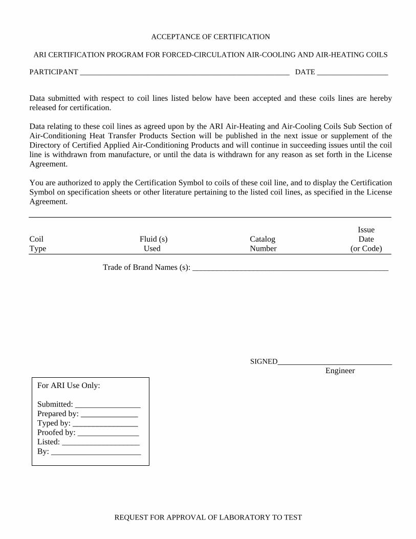
ACCEPTANCE OF CERTIFICATION
ARI CERTIFICATION PROGRAM FOR FORCED-CIRCULATION AIR-COOLING AND AIR-HEATING COILS
PARTICIPANT ________________________________________________________ DATE ___________________ Data submitted with respect to coil lines listed below have been accepted and these coils lines are hereby released for certification. Data relating to these coil lines as agreed upon by the ARI Air-Heating and Air-Cooling Coils Sub Section of Air-Conditioning Heat Transfer Products Section will be published in the next issue or supplement of the Directory of Certified Applied Air-Conditioning Products and will continue in succeeding issues until the coil line is withdrawn from manufacture, or until the data is withdrawn for any reason as set forth in the License Agreement. You are authorized to apply the Certification Symbol to coils of these coil line, and to display the Certification Symbol on specification sheets or other literature pertaining to the listed coil lines, as specified in the License Agreement. Issue Coil Fluid (s) Catalog Date Type Used Number (or Code) Trade of Brand Names (s): ________________________________________________
SIGNED____________________________ Engineer
For ARI Use Only: Submitted: ________________ Prepared by: ______________ Typed by: ________________ Proofed by: _______________ Listed: ___________________ By: ______________________
REQUEST FOR APPROVAL OF LABORATORY TO TEST
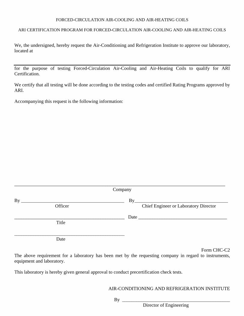
FORCED-CIRCULATION AIR-COOLING AND AIR-HEATING COILS
ARI CERTIFICATION PROGRAM FOR FORCED-CIRCULATION AIR-COOLING AND AIR-HEATING COILS
We, the undersigned, hereby request the Air-Conditioning and Refrigeration Institute to approve our laboratory, located at for the purpose of testing Forced-Circulation Air-Cooling and Air-Heating Coils to qualify for ARI Certification. We certify that all testing will be done according to the testing codes and certified Rating Programs approved by ARI. Accompanying this request is the following information: ________________________________________________________________________________________
Company By ___________________________________________ By_______________________________________ Officer Chief Engineer or Laboratory Director ______________________________________________ Date _____________________________________ Title ______________________________________________ Date
Form CHC-C2 The above requirement for a laboratory has been met by the requesting company in regard to instruments, equipment and laboratory. This laboratory is hereby given general approval to conduct precertification check tests.
AIR-CONDITIONING AND REFRIGERATION INSTITUTE
By _____________________________________________ Director of Engineering
Date ____________________________________________
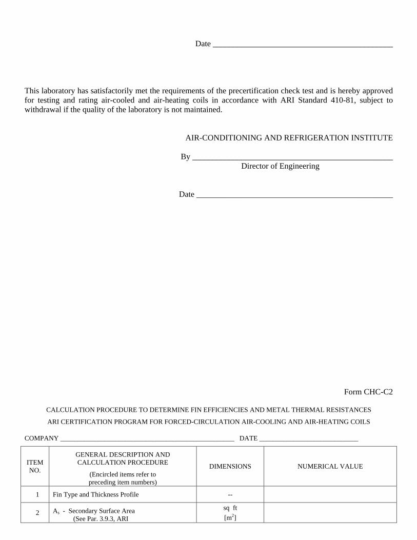
This laboratory has satisfactorily met the requirements of the precertification check test and is hereby approved for testing and rating air-cooled and air-heating coils in accordance with ARI Standard 410-81, subject to withdrawal if the quality of the laboratory is not maintained.
AIR-CONDITIONING AND REFRIGERATION INSTITUTE
By _________________________________________________ Director of Engineering
Date ________________________________________________
Form CHC-C2
CALCULATION PROCEDURE TO DETERMINE FIN EFFICIENCIES AND METAL THERMAL RESISTANCES
ARI CERTIFICATION PROGRAM FOR FORCED-CIRCULATION AIR-COOLING AND AIR-HEATING COILS
COMPANY ___________________________________________________ DATE _____________________________
ITEM NO.
GENERAL DESCRIPTION AND CALCULATION PROCEDURE
(Encircled items refer to preceding item numbers)
DIMENSIONS NUMERICAL VALUE
1 Fin Type and Thickness Profile --
2 As - Secondary Surface Area (See Par. 3.9.3, ARI
sq ft [m2]
Standard 410)
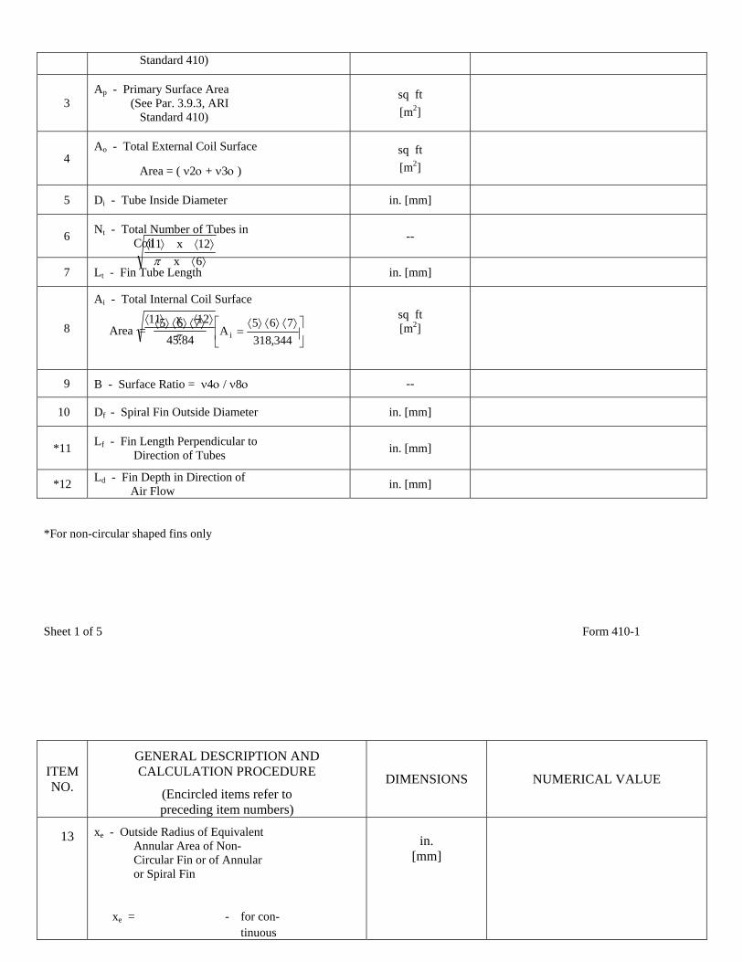
3 Ap - Primary Surface Area (See Par. 3.9.3, ARI Standard 410)
sq ft [m2]
4 Ao - Total External Coil Surface
Area = ( ν2ο + ν3ο )
sq ft [m2]
5 Di - Tube Inside Diameter in. [mm]
6 Nt - Total Number of Tubes in Coil --
7 Lt - Fin Tube Length in. [mm]
8
Ai - Total Internal Coil Surface
Area = 84.45
765 ⟩⟨⟩⟨⟩⟨ ⎥⎦
⎤⎢⎣
⎡ ⟩⟨⟩⟨⟩⟨=
344,318765
A i
sq ft [m2]
9 B - Surface Ratio = ν4ο / ν8ο --
10 Df - Spiral Fin Outside Diameter in. [mm]
*11 Lf - Fin Length Perpendicular to Direction of Tubes in. [mm]
*12 Ld - Fin Depth in Direction of Air Flow in. [mm]
⟩⟨⟩⟨⟩⟨
6x12x11
π
π⟩⟨⟩⟨ 12x11
*For non-circular shaped fins only Sheet 1 of 5 Form 410-1
ITEM NO.
GENERAL DESCRIPTION AND CALCULATION PROCEDURE
(Encircled items refer to preceding item numbers)
DIMENSIONS NUMERICAL VALUE
13 xe - Outside Radius of Equivalent Annular Area of Non- Circular Fin or of Annular or Spiral Fin
xe = - for con- tinuous
in.
[mm]
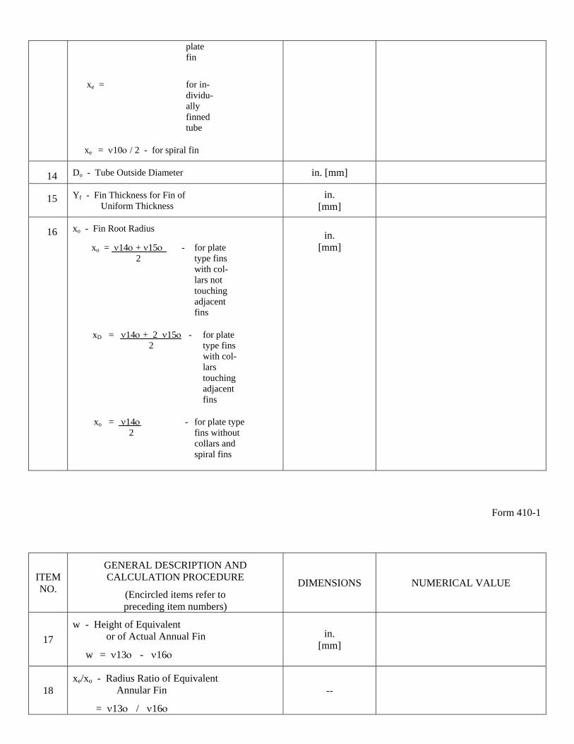
plate fin
xe = for in- dividu- ally finned tube xe = ν10ο / 2 - for spiral fin
14 Do - Tube Outside Diameter in. [mm]
15 Yf - Fin Thickness for Fin of Uniform Thickness
in. [mm]
16 xo - Fin Root Radius
xo = ν14ο + ν15ο - for plate 2 type fins with col- lars not touching adjacent fins
xD = ν14ο + 2 ν15ο - for plate 2 type fins
with col- lars touching adjacent fins
xo = ν14ο - for plate type 2 fins without collars and spiral fins
in.
[mm]
Form 410-1
ITEM NO.
GENERAL DESCRIPTION AND CALCULATION PROCEDURE
(Encircled items refer to preceding item numbers)
DIMENSIONS NUMERICAL VALUE
17 w - Height of Equivalent or of Actual Annual Fin
w = ν13ο - ν16ο
in. [mm]
18 xe/xo - Radius Ratio of Equivalent Annular Fin
= ν13ο / ν16ο
--
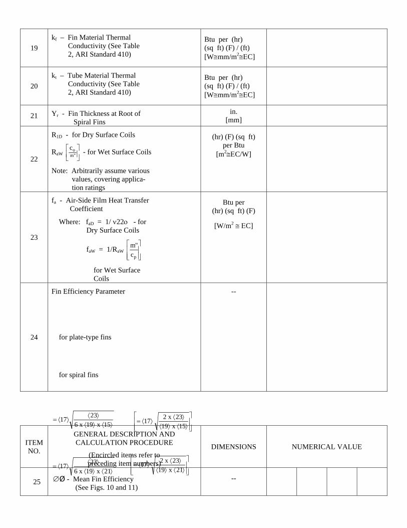
19 kf – Fin Material Thermal Conductivity (See Table 2, ARI Standard 410)
Btu per (hr) (sq ft) (F) / (ft) [W≅mm/m2≅ΕC]
20 kt – Tube Material Thermal Conductivity (See Table 2, ARI Standard 410)
Btu per (hr) (sq ft) (F) / (ft) [W≅mm/m2≅ΕC]
21 Yr - Fin Thickness at Root of Spiral Fins
in. [mm]
22
R1D - for Dry Surface Coils
RaW ⎥⎦⎤
⎢⎣⎡
"moc - for Wet Surface Coils
Note: Arbitrarily assume various values, covering applica- tion ratings
(hr) (F) (sq ft) per Btu
[m2≅ΕC/W]
23
fa - Air-Side Film Heat Transfer Coefficient
Where: faD = 1/ ν22ο - for Dry Surface Coils
faW = 1/RaW ⎥⎥⎦
⎤
⎢⎢⎣
⎡
pc"m
for Wet Surface Coils
Btu per (hr) (sq ft) (F)
[W/m2 ≅ ΕC]
24
Fin Efficiency Parameter
for plate-type fins
for spiral fins
--
ITEM NO.
GENERAL DESCRIPTION AND CALCULATION PROCEDURE
(Encircled items refer to preceding item numbers)
DIMENSIONS NUMERICAL VALUE
25 ∅Ø - Mean Fin Efficiency (See Figs. 10 and 11)
--
⟩⟨⟩⟨⟩⟨
⟩⟨=15x19x6
2317⎥⎥⎦
⎤
⎢⎢⎣
⎡
⟩⟨⟩⟨⟩⟨
⟩⟨=15x19
23x217
⎥⎥⎦
⎤
⎢⎢⎡
⟨2
⎣ ⟩⟨⟩⟨⟩⟨
⟩=21x19
23x17⟩⟨⟩⟨
⟩⟨⟩⟨=
21x19x62317
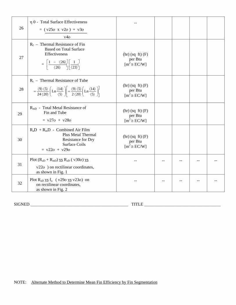
26 η 0 - Total Surface Effectiveness
= ( ν25ο x ν2ο ) + ν3ο
ν4ο
--
27
Rf – Thermal Resistance of Fin Based on Total Surface Effectiveness
= ⎥⎦
⎤⎢⎣
⎡⟩⟨⎥
⎦
⎤⎢⎣
⎡⟩⟨
⟩⟨−231
26261
(hr) (sq ft) (F) per Btu
[m2 ≅ ΕC/W]
28
Rt – Thermal Resistance of Tube
⎥⎦
⎤⎢⎣
⎡⎟⎟⎠
⎞⎜⎜⎝
⎛⟩⟨⟩⟨
⟩⟨⟩⟨⟩⟨
=⎟⎟⎠
⎞⎜⎜⎝
⎛⟩⟨⟩⟨
⟩⟨⟩⟨⟩⟨
=5
14Ln202
595
14Ln202459
(hr) (sq ft) (F) per Btu
[m2 ≅ ΕC/W]
29 RmD - Total Metal Resistance of Fin and Tube
= ν27ο + ν28ο
(hr) (sq ft) (F) per Btu
[m2 ≅ ΕC/W]
30
RaD + RmD - Combined Air Film Plus Metal Thermal Resistance for Dry Surface Coils = ν22ο + ν29ο
(hr) (sq ft) (F) per Btu
[m2 ≅ ΕC/W]
31 Plot (RaD + RmD) vs RaD ( ν30ο) vs
ν22ο ) on rectilinear coordinates, as shown in Fig. 1
-- -- -- -- --
32 Plot RaD vs fa ( ν29ο vs ν23ο) on on rectilinear coordinates, as shown in Fig. 2
-- -- -- -- --
SIGNED ______________________________________________ TITLE ____________________________________ NOTE: Alternate Method to Determine Mean Fin Efficiency by Fin Segmentation
A more accurate, but more involved, method of calculating ∅ and Rf for non-circular shaped fins is described as Method (2), pages 313-315 in Reference A9 of ARI Standard 410. The mean values of ∅, as determined by this alternate method, will be somewhat lower than those calculated by the simpler, equivalent annular area method given in the above procedure.
For non-circular fin designs of large size, in combination with thin, low thermal conductivity fin material, this alternate method is recommended. The difference in ∅, as calculated by the two methods, also becomes greater as the fin becomes more oblong. If this alternate method is used, it is recommended that the fin efficiency, ∅, for each of the individual fin sectors be based on data by K. A. Gardner (Reference A8 of ARI Standard 410), rather than that given in Reference A9.
Where this alternate method is used, please include all necessary information and calculations and attach them to this form.
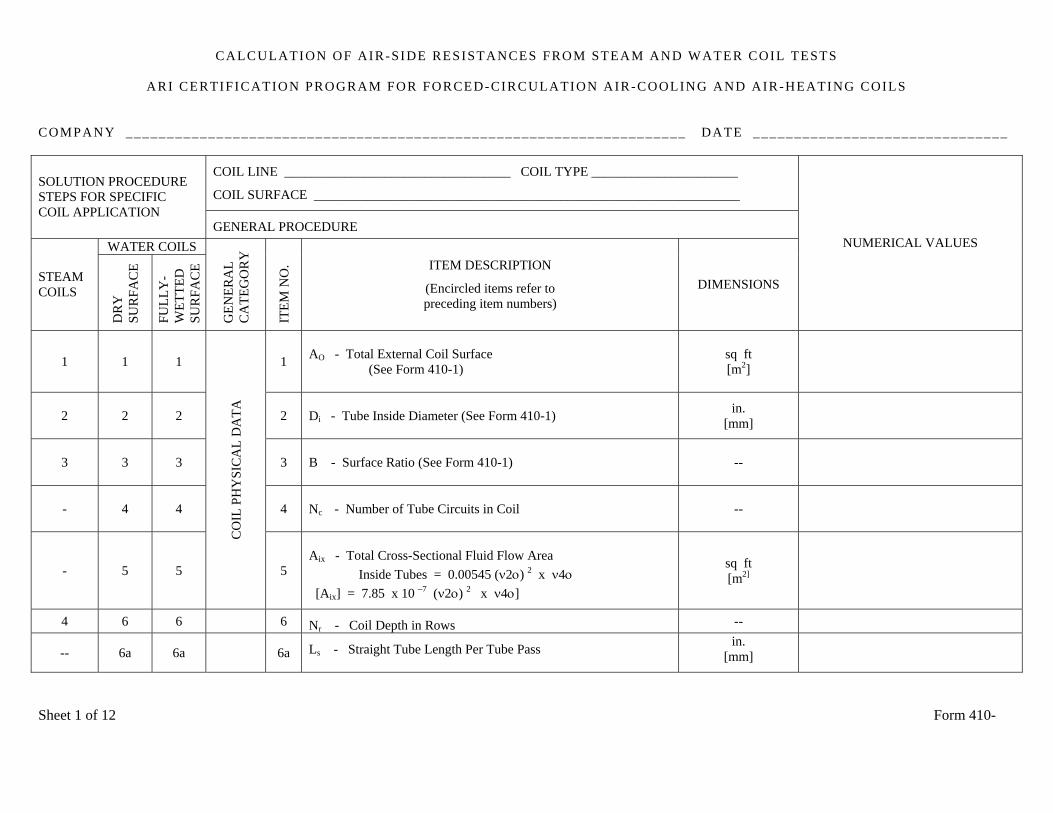
CALCULATION OF AIR-SIDE RESISTANCES FROM STEAM AND WATER COIL TESTS
ARI CERTIFICATION PROGRAM FOR FORCED-CIRCULATION AIR-COOLING AND AIR-HEATING COILS
COMPANY ____________________________________________________________________ DATE _______________________________
COIL LINE __________________________________ COIL TYPE ______________________
COIL SURFACE ________________________________________________________________ SOLUTION PROCEDURE STEPS FOR SPECIFIC COIL APPLICATION
GENERAL PROCEDURE WATER COILS
STEAM COILS
DR
Y
SU
RFA
CE
FU
LLY
- W
ETTE
D
SU
RFA
CE
GEN
ERA
L C
ATE
GO
RY
ITE
M N
O.
ITEM DESCRIPTION
(Encircled items refer to preceding item numbers)
DIMENSIONS
NUMERICAL VALUES
1 1 1 1
AO - Total External Coil Surface (See Form 410-1)
sq ft [m2]
2 2 2 2 Di - Tube Inside Diameter (See Form 410-1)
in. [mm]
3 3 3 3 B - Surface Ratio (See Form 410-1)
--
- 4 4 4 Nc - Number of Tube Circuits in Coil
--
- 5 5
CO
IL P
HY
SIC
AL
DA
TA
5
Aix - Total Cross-Sectional Fluid Flow Area Inside Tubes = 0.00545 (ν2ο) 2 x ν4ο [Aix] = 7.85 x 10 –7 (ν2ο) 2 x ν4ο]
sq ft [m2]
4 6 6 6 Nr - Coil Depth in Rows --
-- 6a 6a
6a Ls - Straight Tube Length Per Tube Pass in. [mm]
Sheet 1 of 12 Form 410-
SOLUTION PROCEDURE
STEPS FOR SPECIFIC COIL APPLICATION
GENERAL PROCEDURE NUMERICAL VALUES
WATER COILS TEST RUN NUMBER
STEAM COILS
DR
Y
SU
RFA
CE
FULL
Y-
WET
TED
S
UR
FAC
E G
ENER
AL
CA
TEG
OR
Y
ITE
M N
O. ITEM DESCRIPTION
(Encircled items refer to preceding item numbers)
DIMENSIONS 1 2 3 4
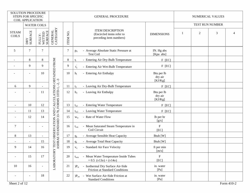
5 7 7 7 pS - Average Absolute Static Pressure at Test Coil
IN. Hg abs [Kpa abs]
- 8 8 8 tl - Entering Air Dry-Bulb Temperature F [ΕC]
- 9 9 9 'lt - Entering Air Wet-Bulb Temperature F [ΕC]
- - 10 10 hl - Entering Air Enthalpy Btu per lb dry air
[KJ/Kg]
6 9 - 11 t2 - Leaving Air Dry-Bulb Temperature F [ΕC]
- - 11 12 h2 - Leaving Air Enthalpy Btu per lb dry air
[KJ/Kg]
- 10 12 13 twl - Entering Water Temperature F [ΕC]
- 11 13 14 tw2 - Leaving Water Temperature F [ΕC]
- 12 14 15 ww - Rate of Water Flow lb per hr [g/s]
7 - - 16 tvm - Mean Saturated Steam Temperature in Coil Circuit
F [ΕC]
8 13 - 17 qs - Average Sensible Heat Capacity Btuh [W]
- - 15 18 qr - Average Total Heat Capacity Btuh [W]
9 14 16 19 va - Standard Air Face Velocity ft per min [m/s]
- 15 17 20 twm - Mean Water Temperature Inside Tubes = 0.5 (ν13ο) + (ν14ο)
F [ΕC]
10 16 - 21 )Pst - Isothermal Dry Surface Air-Side Friction at Standard Conditions
in. water [Pa]
- - 18
LAB
OR
ATO
RY
TES
T O
BSE
RV
ATI
ON
AN
D C
ALC
ULA
TIO
NS
OB
TAIN
ED F
RO
M
ASH
RA
E ST
AN
DA
RD
33-
78, F
OR
MS
33TD
-1, -
2, -3
22 )Psw - Wet Surface Air-Side Friction at Standard Conditions
in. water [Pa]
Sheet 2 of 12 Form 410-2
SOLUTION PROCEDURE STEPS FOR SPECIFIC COIL APPLICATION
GENERAL PROCEDURE NUMERICAL VALUES
WATER COILS TEST RUN NUMBER
STEAM COILS
DR
Y
SU
RFA
CE
FULL
Y-
WET
TED
S
UR
FAC
E G
ENER
AL
CA
TEG
OR
Y
ITE
M N
O. ITEM DESCRIPTION
(Encircled items refer to preceding item numbers)
DIMENSIONS 1 2 3 4
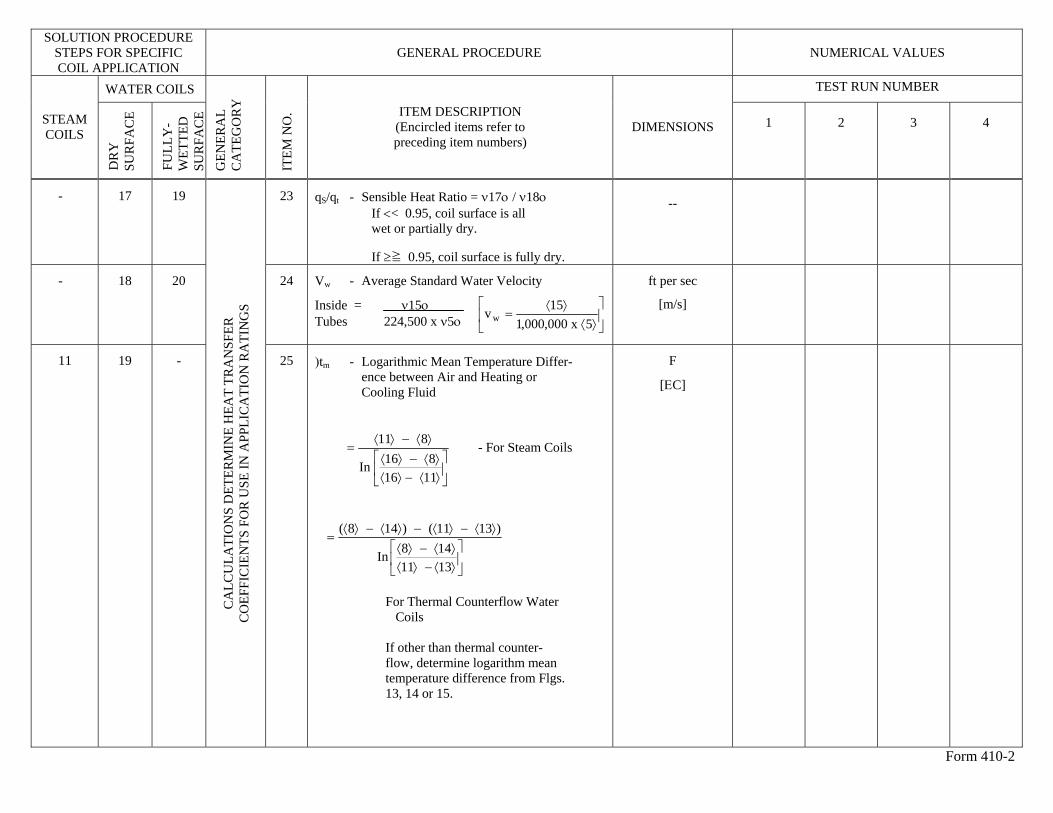
- 17 19 23 qS/qt - Sensible Heat Ratio = ν17ο / ν18ο If << 0.95, coil surface is all wet or partially dry.
If ≥≧ 0.95, coil surface is fully dry.
--
- 18 20 24 Vw - Average Standard Water Velocity
Inside = ν15ο Tubes 224,500 x ν5ο
ft per sec
[m/s]
11 19 -
CA
LCU
LATI
ON
S D
ETER
MIN
E H
EAT
TRA
NSF
ER
CO
EFFI
CIE
NTS
FO
R U
SE IN
APP
LIC
ATI
ON
RA
TIN
GS
25 )tm - Logarithmic Mean Temperature Differ- ence between Air and Heating or Cooling Fluid
⎥⎦
⎤⎢⎣
⎡⟩⟨−⟩⟨⟩⟨−⟩⟨
⟩⟨−⟩⟨=
1116816In
811 - For Steam Coils
⎥⎦
⎤⎢⎣
⎡⟩⟨−⟩⟨⟩⟨−⟩⟨
⟩⟨−⟩⟨−⟩⟨−⟩⟨=
1311148In
)1311()148(
For Thermal Counterflow Water Coils If other than thermal counter- flow, determine logarithm mean temperature difference from Flgs. 13, 14 or 15.
F
[ΕC]
Form 410-2
⎥⎦
⎤⎢⎣
⎡⟩⟨
⟩⟨=
5x000,000,115v w
SOLUTION PROCEDURE STEPS FOR SPECIFIC COIL APPLICATION
GENERAL PROCEDURE NUMERICAL VALUES
WATER COILS TEST RUN NUMBER
STEAM COILS
DR
Y
SU
RFA
CE
FULL
Y-
WET
TED
S
UR
FAC
E G
ENER
AL
CA
TEG
OR
Y
ITE
M N
O. ITEM DESCRIPTION
(Encircled items refer to preceding item numbers)
DIMENSIONS 1 2 3 4
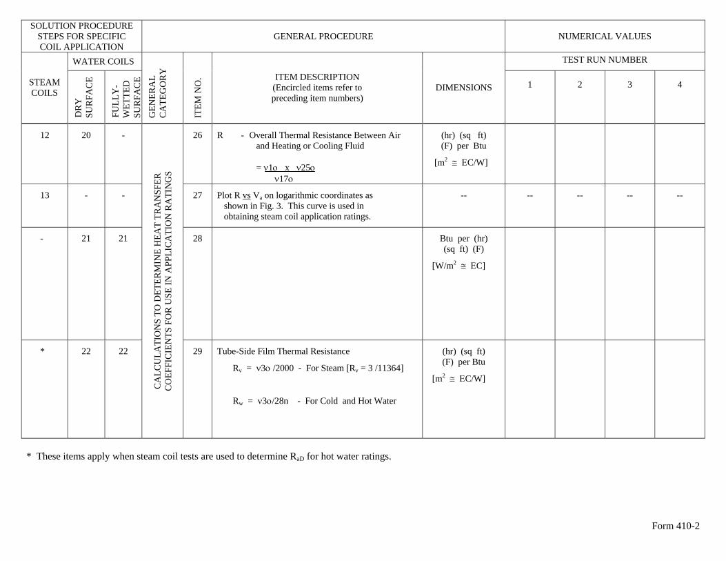
12 20 - 26 R - Overall Thermal Resistance Between Air and Heating or Cooling Fluid = ν1ο x ν25ο ν17ο
(hr) (sq ft) (F) per Btu
[m2 ≅ ΕC/W]
13 - - 27 Plot R vs Va on logarithmic coordinates as shown in Fig. 3. This curve is used in obtaining steam coil application ratings.
-- -- -- -- --
- 21 21 28
Btu per (hr) (sq ft) (F)
[W/m2 ≅ ΕC]
* 22 22
CA
LCU
LATI
ON
S TO
DET
ERM
INE
HEA
T TR
AN
SFER
C
OEF
FIC
IEN
TS F
OR
USE
IN A
PPLI
CA
TIO
N R
ATI
NG
S
29 Tube-Side Film Thermal Resistance
Rv = ν3ο /2000 - For Steam [Rv = 3 /11364]
Rw = ν3ο/28n - For Cold and Hot Water
(hr) (sq ft) (F) per Btu
[m2 ≅ ΕC/W]
* These items apply when steam coil tests are used to determine RaD for hot water ratings.
Form 410-2
SOLUTION PROCEDURE
STEPS FOR SPECIFIC COIL APPLICATION
GENERAL PROCEDURE NUMERICAL VALUES
WATER COILS TEST RUN NUMBER
STEAM COILS
DR
Y
SU
RFA
CE
FULL
Y-
WET
TED
S
UR
FAC
E G
ENER
AL
CA
TEG
OR
Y
ITE
M N
O. ITEM DESCRIPTION
(Encircled items refer to preceding item numbers)
DIMENSIONS 1 2 3 4
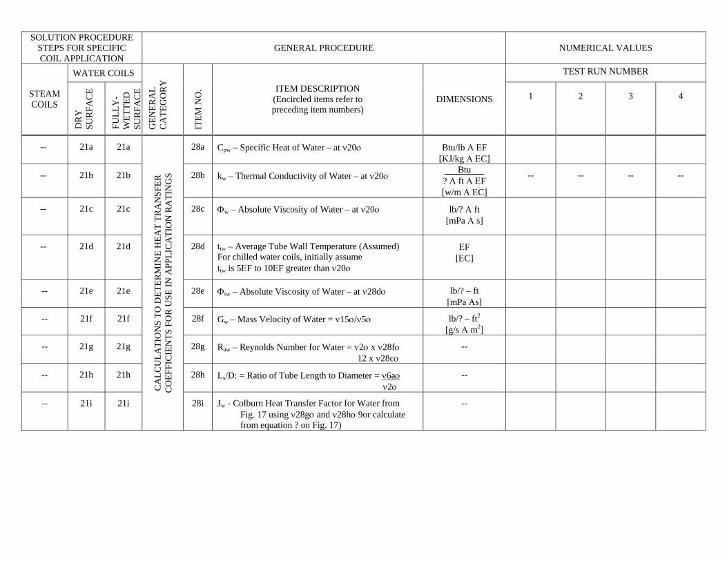
-- 21a 21a 28a Cpw – Specific Heat of Water – at ν20ο Btu/lb Α ΕF [KJ/kg Α ΕC]
-- 21b 21b 28b kw – Thermal Conductivity of Water – at ν20ο Btu
? Α ft Α ΕF [w/m Α ΕC]
-- -- -- --
-- 21c 21c 28c Φw – Absolute Viscosity of Water – at ν20ο
lb/? Α ft [mPa Α s]
-- 21d 21d 28d ttw – Average Tube Wall Temperature (Assumed) For chilled water coils, initially assume ttw is 5ΕF to 10ΕF greater than ν20ο
ΕF [ΕC]
-- 21e 21e 28e Φtw – Absolute Viscosity of Water – at ν28dο lb/? – ft [mPa Αs]
-- 21f 21f 28f Gw – Mass Velocity of Water = ν15ο/ν5ο lb/? – ft2
[g/s Α m2]
-- 21g 21g 28g Raw – Reynolds Number for Water = ν2ο x ν28fο 12 x ν28cο
--
-- 21h 21h 28h Ls/D: = Ratio of Tube Length to Diameter = ν6aο ν2ο
--
-- 21i 21i
CA
LCU
LATI
ON
S TO
DET
ERM
INE
HEA
T TR
AN
SFER
C
OEF
FIC
IEN
TS F
OR
USE
IN A
PPLI
CA
TIO
N R
ATI
NG
S
28i Jw - Colburn Heat Transfer Factor for Water from Fig. 17 using ν28gο and ν28hο 9or calculate from equation ? on Fig. 17)
--
SOLUTION PROCEDURE
STEPS FOR SPECIFIC COIL APPLICATION
GENERAL PROCEDURE NUMERICAL VALUES
WATER COILS TEST RUN NUMBER
STEAM COILS
DR
Y
SU
RFA
CE
FULL
Y-
WET
TED
S
UR
FAC
E G
ENER
AL
CA
TEG
OR
Y
ITE
M N
O. ITEM DESCRIPTION
(Encircled items refer to preceding item numbers)
DIMENSIONS 1 2 3 4
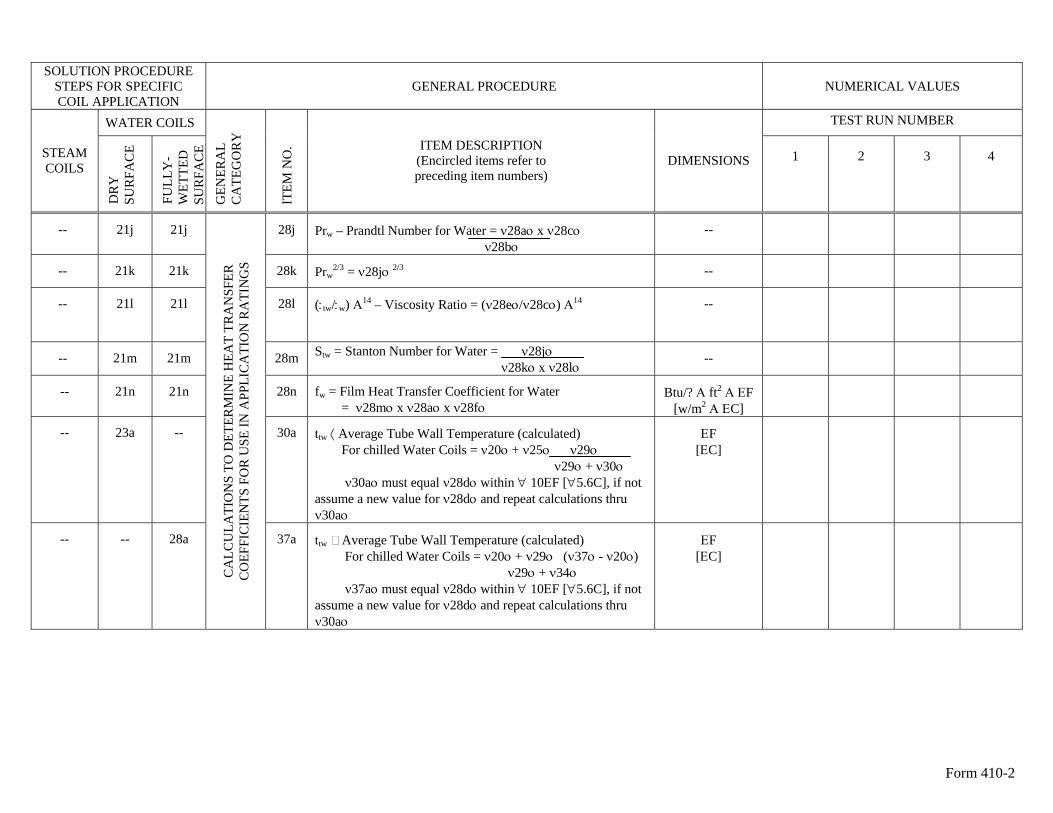
-- 21j 21j 28j Prw – Prandtl Number for Water = ν28aο x ν28cο ν28bο
--
-- 21k 21k 28k Prw2/3 = ν28jο 2/3 --
-- 21l 21l 28l (:tw/:w) Α14 – Viscosity Ratio = (ν28eο/ν28cο) Α14 --
-- 21m 21m 28m Stw = Stanton Number for Water = ν28jο ν28kο x ν28lο
--
-- 21n 21n 28n fw = Film Heat Transfer Coefficient for Water = ν28mο x ν28aο x ν28fο
Btu/? Α ft2 Α ΕF [w/m2 Α ΕC]
-- 23a -- 30a ttw ⟨ Average Tube Wall Temperature (calculated) For chilled Water Coils = ν20ο + ν25ο ν29ο ν29ο + ν30ο ν30aο must equal ν28dο within ∀ 10ΕF [∀5.6C], if not assume a new value for ν28dο and repeat calculations thru ν30aο
ΕF [ΕC]
-- -- 28a
CA
LCU
LATI
ON
S TO
DET
ERM
INE
HEA
T TR
AN
SFER
C
OEF
FIC
IEN
TS F
OR
USE
IN A
PPLI
CA
TIO
N R
ATI
NG
S
37a ttw Average Tube Wall Temperature (calculated) For chilled Water Coils = ν20ο + ν29ο (ν37ο - ν20ο) ν29ο + ν34ο ν37aο must equal ν28dο within ∀ 10ΕF [∀5.6C], if not assume a new value for ν28dο and repeat calculations thru ν30aο
ΕF [ΕC]
Form 410-2
SOLUTION PROCEDURE STEPS FOR SPECIFIC COIL APPLICATION
GENERAL PROCEDURE
TO SOLVE FOR ROWS DEEP
(Nr)
TO SOLVE FOR CAPACITY
(qs)
STEAM COILS
HOT OR COLD
WATER COILS
STEAM COILS
HOT OR COLD
WATER COILS
GEN
ERA
L C
ATE
GO
RY
ITE
M N
O.
ITEM DESCRIPTION (Encircled items refer to preceding item numbers)
DIMENSIONS NUMERICAL
VALUES
-- 23a -- 23a
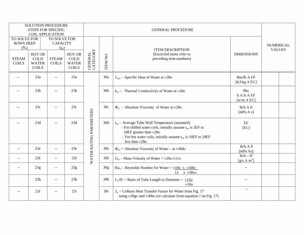
30a Cpw – Specific Heat of Water at ν28ο Btu/lb Α ΕF [KJ/kg Α ΕC]
-- 23b -- 23b 30b kw -- Thermal Conductivity of Water at ν28ο Btu h Α ft Α ΕF [w/m Α ΕC]
-- 23c -- 23c 30c Φw – Absolute Viscosity of Water at ν28ο lb/h Α ft [mPa Α s]
-- 23d -- 23d 30d ttw – Average Tube Wall Temperature (assumed) - For chilled water coils, initially assume ttw is 5ΕF to 10ΕF greater than ν28ο - For hot water coils, initially assume ttw is 10ΕF to 20ΕF less than ν28ο
ΕF [ΕC]
-- 23e -- 23e 30e Φtw = Absolute Viscosity of Water – at ν30dο lb/h Α ft [mPa Αs]
-- 23f -- 23f 30f Gw – Mass Velosity of Water = ν29ο/ν11ο lb/h – ft2
[g/s Α m2]
-- 23g -- 23g 30g Raw – Reynolds Number for Water = ν10ο x ν30fο 12 x ν30cο
--
23h -- 23h 30h Ls/D: = Ratio of Tube Length to Diameter = ν12ο ν10ο
--
-- 23i -- 23i
WA
TER
RA
TIN
G P
AR
AM
ETER
S
30i Jw – Colburn Heat Transfer Factor for Water from Fig. 17 using ν30gο and ν30hο (or calculate from equation ? on Fig. 17)
--
Form 410-5
SOLUTION PROCEDURE
STEPS FOR SPECIFIC COIL APPLICATION
GENERAL PROCEDURE
TO SOLVE FOR ROWS DEEP
(Nr)
TO SOLVE FOR CAPACITY
(qs)
STEAM COILS
HOT OR COLD
WATER COILS
STEAM COILS
HOT OR COLD
WATER COILS
GEN
ERA
L C
ATE
GO
RY
ITE
M N
O.
ITEM DESCRIPTION (Encircled items refer to preceding item numbers)
DIMENSIONS NUMERICAL
VALUES
-- 23j -- 23j
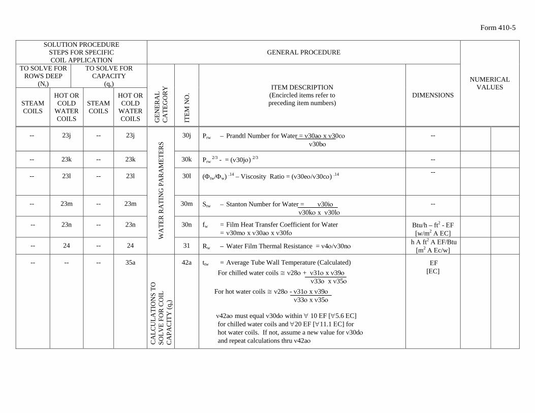
30j Prw – Prandtl Number for Water = ν30aο x ν30cο ν30bο
--
-- 23k -- 23k 30k Prw 2/3 - = (ν30jο) 2/3 --
-- 23l -- 23l 30l (Φtw/Φw) .14 – Viscosity Ratio = (ν30eο/ν30cο) .14 --
-- 23m -- 23m 30m Stw – Stanton Number for Water = ν30iο ν30kο x ν30lο
--
-- 23n -- 23n 30n fw = Film Heat Transfer Coefficient for Water = ν30mο x ν30aο x ν30fο
Btu/h – ft2 - ΕF [w/m2 Α ΕC]
-- 24 -- 24
WA
TER
RA
TIN
G P
AR
AM
ETER
S
31 Rw – Water Film Thermal Resistance = ν4ο/ν30nο h Α ft2 Α ΕF/Btu [m2 Α Εc/w]
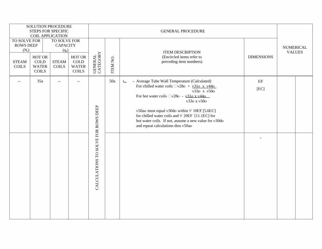
-- -- -- 35a
CA
LCU
LATI
ON
S TO
S
OLV
E FO
R C
OIL
C
APA
CIT
Y (q
s)
42a ttw = Average Tube Wall Temperature (Calculated) For chilled water coils ≅ ν28ο + ν31ο x ν39ο ν33ο x ν35ο For hot water coils ≅ ν28ο - ν31ο x ν39ο ν33ο x ν35ο ν42aο must equal ν30dο within ∀ 10 ΕF [∀5.6 ΕC] for chilled water coils and ∀20 ΕF [∀11.1 ΕC] for hot water coils. If not, assume a new value for ν30dο and repeat calculations thru ν42aο
ΕF [ΕC]
SOLUTION PROCEDURE
STEPS FOR SPECIFIC COIL APPLICATION
GENERAL PROCEDURE NUMERICAL VALUES
WATER COILS TEST RUN NUMBER
STEAM COILS
DR
Y
SU
RFA
CE
FULL
Y-
WET
TED
S
UR
FAC
E G
ENER
AL
CA
TEG
OR
Y
ITE
M N
O. ITEM DESCRIPTION
(Encircled items refer to preceding item numbers)
DIMENSIONS 1 2 3 4
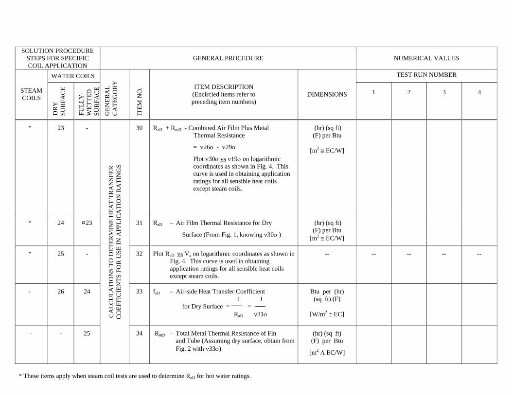
* 23 - 30 RaD + RmD - Combined Air Film Plus Metal Thermal Resistance
= ν26ο - ν29ο
Plot ν30ο vs ν19ο on logarithmic coordinates as shown in Fig. 4. This curve is used in obtaining application ratings for all sensible heat coils except steam coils.
(hr) (sq ft) (F) per Btu
[m2 ≅ ΕC/W]
* 24 ¤23 31 RaD – Air Film Thermal Resistance for Dry
Surface (From Fig. 1, knowing ν30ο )
(hr) (sq ft) (F) per Btu
[m2 ≅ ΕC/W]
* 25 - 32 Plot RaD vs Va on logarithmic coordinates as shown in Fig. 4. This curve is used in obtaining application ratings for all sensible heat coils except steam coils.
-- -- -- -- --
- 26 24 33 faD – Air-side Heat Transfer Coefficient 1 1 for Dry Surface = = RaD ν31ο
Btu per (hr) (sq ft) (F)
[W/m2 ≅ ΕC]
- - 25
CA
LCU
LATI
ON
S TO
DET
ERM
INE
HEA
T TR
AN
SFER
C
OEF
FIC
IEN
TS F
OR
USE
IN A
PPLI
CA
TIO
N R
ATI
NG
S
34 RmD – Total Metal Thermal Resistance of Fin and Tube (Assuming dry surface, obtain from Fig. 2 with ν33ο)
(hr) (sq ft) (F) per Btu
[m2 Α ΕC/W]
* These items apply when steam coil tests are used to determine RaD for hot water ratings.
¤ For fully-wetted coils, read value of RaD from Fig. 4 as determined from dry coil tests.

SOLUTION PROCEDURE
STEPS FOR SPECIFIC COIL APPLICATION
GENERAL PROCEDURE NUMERICAL VALUES
WATER COILS TEST RUN NUMBER
STEAM COILS
DR
Y
SU
RFA
CE
FULL
Y-
WET
TED
S
UR
FAC
E G
ENER
AL
CA
TEG
OR
Y
ITE
M N
O. ITEM DESCRIPTION
(Encircled items refer to preceding item numbers)
DIMENSIONS 1 2 3 4
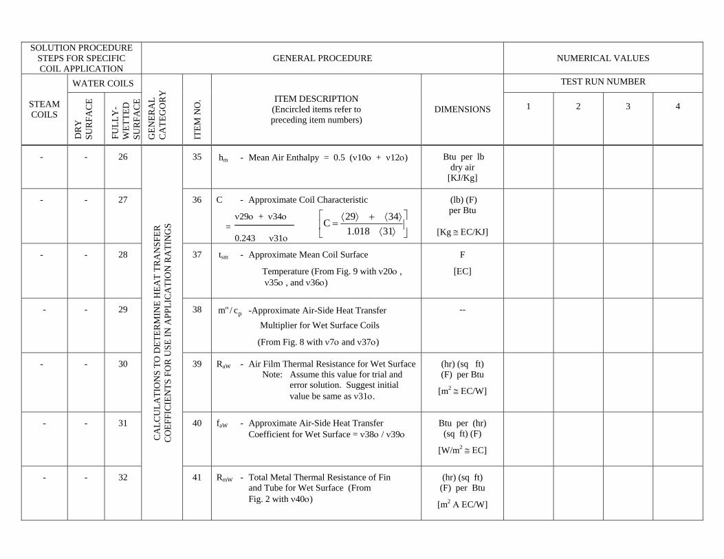
- - 26 35 hm - Mean Air Enthalpy = 0.5 (ν10ο + ν12ο)
Btu per lb dry air
[KJ/Kg]
- - 27 36 C - Approximate Coil Characteristic
ν29ο + ν34ο = 0.243 ν31ο
(lb) (F) per Btu
[Kg ≅ ΕC/KJ]
- - 28 37 tsm - Approximate Mean Coil Surface
Temperature (From Fig. 9 with ν20ο , ν35ο , and ν36ο)
F
[ΕC]
- - 29 38 pc/"m -Approximate Air-Side Heat Transfer Multiplier for Wet Surface Coils
(From Fig. 8 with ν7ο and ν37ο)
--
- - 30 39 RaW - Air Film Thermal Resistance for Wet Surface Note: Assume this value for trial and error solution. Suggest initial value be same as ν31ο.
(hr) (sq ft) (F) per Btu
[m2 ≅ ΕC/W]
- - 31 40 faW - Approximate Air-Side Heat Transfer Coefficient for Wet Surface = ν38ο / ν39ο
Btu per (hr) (sq ft) (F)
[W/m2 ≅ ΕC]
- - 32
CA
LCU
LATI
ON
S TO
DET
ERM
INE
HEA
T TR
AN
SFER
C
OEF
FIC
IEN
TS F
OR
USE
IN A
PPLI
CA
TIO
N R
ATI
NG
S
41 RmW - Total Metal Thermal Resistance of Fin and Tube for Wet Surface (From Fig. 2 with ν40ο)
(hr) (sq ft) (F) per Btu
[m2 Α ΕC/W]
⎥⎦
⎤⎢⎣
⎡⟩⟨⟩⟨+⟩⟨
=31018.1
3429C
SOLUTION PROCEDURE
STEPS FOR SPECIFIC COIL APPLICATION
GENERAL PROCEDURE NUMERICAL VALUES
WATER COILS TEST RUN NUMBER
STEAM COILS
DR
Y
SU
RFA
CE
FULL
Y-
WET
TED
S
UR
FAC
E G
ENER
AL
CA
TEG
OR
Y
ITE
M N
O. ITEM DESCRIPTION
(Encircled items refer to preceding item numbers)
DIMENSIONS 1 2 3 4
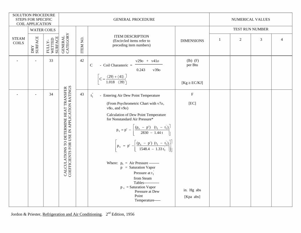
- - 33 42 ν29ο + ν41ο C - Coil Charasteric = 0.243 ν39ο
(lb) (F) per Btu
[Kg ≅ ΕC/KJ]
- - 34
CA
LCU
LATI
ON
S TO
DET
ERM
INE
HEA
T TR
AN
SFER
C
OEF
FIC
IEN
TS F
OR
USE
IN A
PPLI
CA
TIO
N R
ATI
NG
S
43 "lt - Entering Air Dew Point Temperature
(From Psychrometric Chart with ν7ο, ν8ο, and ν9ο)
Calculation of Dew Point Temperature for Nonstandard Air Pressure* Where: ps = Air Pressure -------- p = Saturation Vapor
' Pressure at t l
from Steam Tables------------ p v = Saturation Vapor Pressure at Dew Point Temperature-----
F
[ΕC]
in. Hg abs
[Kpa abs]
⎥⎦
⎤⎢⎣
⎡⟩⟨⟩⟨+⟩⟨
=1
C39018.4129
⎥⎥⎦
⎤
⎢⎢⎣
⎡
−−−
−=t44.12830
)tt()'pp('pp
'l1s
v
⎥⎥⎦
⎤
⎢⎢⎣
⎡
⎥⎥⎦
⎤
⎢⎢⎣
⎡
−
−−−= '
l
'l1s
v t33.14.1548)tt()'pp(
'pp
Jordon & Priester, Refrigeration and Air Conditioning. 2nd Edition, 1956
SOLUTION PROCEDURE
STEPS FOR SPECIFIC COIL APPLICATION
GENERAL PROCEDURE NUMERICAL VALUES
WATER COILS TEST RUN NUMBER
STEAM COILS
DR
Y
SU
RFA
CE
FULL
Y-
WET
TED
S
UR
FAC
E G
ENER
AL
CA
TEG
OR
Y
ITE
M N
O. ITEM DESCRIPTION
(Encircled items refer to preceding item numbers)
DIMENSIONS 1 2 3 4
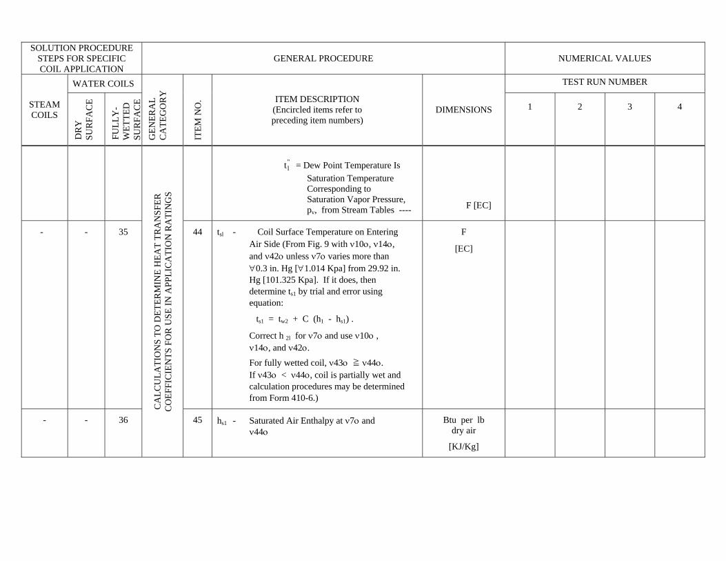
= Dew Point Temperature Is "
lt Saturation Temperature Corresponding to Saturation Vapor Pressure, pv, from Stream Tables ----
F [ΕC]
- - 35 44 tsl - Coil Surface Temperature on Entering Air Side (From Fig. 9 with ν10ο, ν14ο, and ν42ο unless ν7ο varies more than ∀0.3 in. Hg [∀1.014 Kpa] from 29.92 in. Hg [101.325 Kpa]. If it does, then determine ts1 by trial and error using equation:
ts1 = tw2 + C (h1 - hs1) .
Correct h 2l for ν7ο and use ν10ο , ν14ο, and ν42ο. For fully wetted coil, ν43ο ≧ ν44ο. If ν43ο < ν44ο, coil is partially wet and calculation procedures may be determined from Form 410-6.)
F
[ΕC]
- - 36
CA
LCU
LATI
ON
S TO
DET
ERM
INE
HEA
T TR
AN
SFER
C
OEF
FIC
IEN
TS F
OR
USE
IN A
PPLI
CA
TIO
N R
ATI
NG
S
45 hs1 - Saturated Air Enthalpy at ν7ο and ν44ο
Btu per lb dry air
[KJ/Kg]
SOLUTION PROCEDURE STEPS FOR SPECIFIC COIL APPLICATION
GENERAL PROCEDURE
TO SOLVE FOR ROWS DEEP
(Nr)
TO SOLVE FOR CAPACITY
(qs)
STEAM COILS
HOT OR COLD
WATER COILS
STEAM COILS
HOT OR COLD
WATER COILS
GEN
ERA
L C
ATE
GO
RY
ITE
M N
O.
ITEM DESCRIPTION (Encircled items refer to preceding item numbers)
DIMENSIONS NUMERICAL
VALUES
-- 35a -- --
50a ttw – Average Tube Wall Temperature (Calculated) For chilled water coils ν28ο + ν31ο x ν44ο ν33ο x ν50ο For hot water coils ν28ο - ν31ο x ν44ο ν33ο x ν50ο ν50aο must equal ν30dο within ∀ 10ΕF [5.6ΕC] for chilled water coils and ∀ 20ΕF [11.1ΕC] for hot water coils. If not, assume a new value for ν30dο and repeat calculations thru ν50aο
ΕF
[ΕC]
CA
LCU
LATI
ON
S TO
SO
LVE
FOR
RO
WS
DEE
P
-
SOLUTION PROCEDURE STEPS FOR SPECIFIC COIL APPLICATION
GENERAL PROCEDURE
COLD WATER COILS
VOLATILE REFRIGERANT
COILS
PAR
TIA
LLY
W
ET
SUR
FAC
E
FULL
Y
WET
SU
RFA
CE
PAR
TIA
LLY
W
ET
SUR
FAC
E
FULL
Y
WET
SU
RFA
CE
GEN
ERA
L C
ATE
GO
RY
ITE
M N
O.
ITEM DESCRIPTION (Encircled items refer to preceding item numbers)
DIMENSIONS
NUMERICAL VALUES
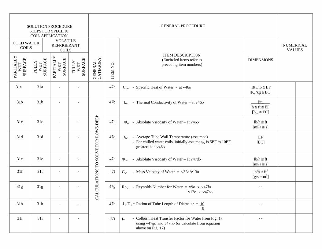
31a 31a - - 47a Cpw - Specific Heat of Water - at ν46ο Btu/lb ≅ ΕF [KJ/kg ≅ ΕC]
31b 31b - - 47b kw - Thermal Conductivity of Water – at ν46ο Btu h ≅ ft ≅ ΕF [w/m ≅ ΕC]
31c 31c - - 47c Φw - Absolute Viscosity of Water – at ν46ο lb/h ≅ ft [mPa ≅ s]
31d 31d - - 47d ttw - Average Tube Wall Temperature (assumed) - For chilled water coils, initially assume ttw is 5ΕF to 10ΕF greater than ν46ο
ΕF [ΕC]
31e 31e - - 47e Φtw - Absolute Viscosity of Water – at ν47dο lb/h ≅ ft [mPa ≅ s]
31f 31f - - 47f Gw - Mass Velosity of Water = ν32ο/ν13ο lb/h ≅ ft2
[g/s ≅ m2]
31g 31g - - 47g Raw - Reynolds Number for Water = ν9ο x ν47fο ν12ο x ν47cο
- -
31h 31h - - 47h Ls/D1 = Ration of Tube Length of Diameter = 10 9
- -
31i 31i - -
CA
LCU
LATI
ON
S TO
SO
LVE
FOR
RO
WS
DEE
P
47i jw - Colburn Heat Transfer Factor for Water from Fig. 17 using ν47gο and ν47hο (or calculate from equation above on Fig. 17)
- -
SOLUTION PROCEDURE STEPS FOR SPECIFIC COIL APPLICATION
GENERAL PROCEDURE
COLD WATER COILS
VOLATILE REFRIGERANT
COILS
PAR
TIA
LLY
W
ET
SUR
FAC
E
FULL
Y
WET
SU
RFA
CE
PAR
TIA
LLY
W
ET
SUR
FAC
E
FULL
Y
WET
SU
RFA
CE
GEN
ERA
L C
ATE
GO
RY
ITE
M N
O.
ITEM DESCRIPTION (Encircled items refer to preceding item numbers)
DIMENSIONS NUMERICAL
VALUES
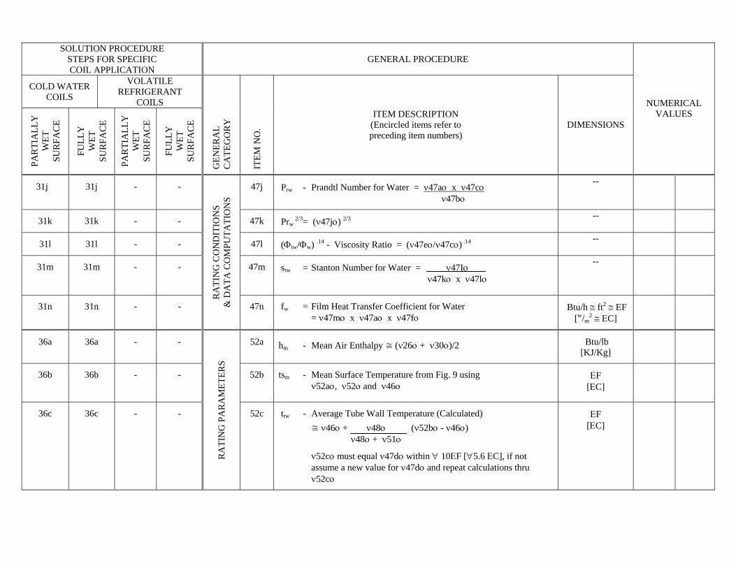
31j 31j - - 47j Prw - Prandtl Number for Water = ν47aο x ν47cο ν47bο
--
31k 31k - - 47k Prw 2/3 = (ν47jο) 2/3 --
31l 31l - - 47l (Φtw/Φw) .14 - Viscosity Ratio = (ν47eο/ν47cο) .14 --
31m 31m - - 47m stw = Stanton Number for Water = ν47Iο ν47kο x ν47lο
--
31n 31n - -
RA
TIN
G C
ON
DIT
ION
S &
DA
TA C
OM
PUTA
TIO
NS
47n fw = Film Heat Transfer Coefficient for Water = ν47mο x ν47aο x ν47fο
Btu/h ≅ ft2 ≅ ΕF [w/m
2 ≅ ΕC]
36a 36a - - 52a hm - Mean Air Enthalpy ≅ (ν26ο + ν30ο)/2 Btu/lb [KJ/Kg]
36b 36b - - 52b tsm - Mean Surface Temperature from Fig. 9 using ν52aο, ν52ο and ν46ο
ΕF [ΕC]
36c 36c - -
RA
TIN
G P
AR
AM
ETER
S
52c ttw - Average Tube Wall Temperature (Calculated) ≅ ν46ο + ν48ο (ν52bο - ν46ο) ν48ο + ν51ο
ν52cο must equal ν47dο within ∀ 10ΕF [∀5.6 ΕC], if not assume a new value for ν47dο and repeat calculations thru ν52cο
ΕF [ΕC]
SOLUTION PROCEDURE STEPS FOR SPECIFIC COIL APPLICATION
GENERAL PROCEDURE
COLD WATER COILS
VOLATILE REFRIGERANT
COILS
PAR
TIA
LLY
W
ET
SUR
FAC
E
FULL
Y
WET
SU
RFA
CE
PAR
TIA
LLY
W
ET
SUR
FAC
E
FULL
Y
WET
SU
RFA
CE
GEN
ERA
L C
ATE
GO
RY
ITE
M N
O.
ITEM DESCRIPTION (Encircled items refer to preceding item numbers)
DIMENSIONS NUMERICAL
VALUES
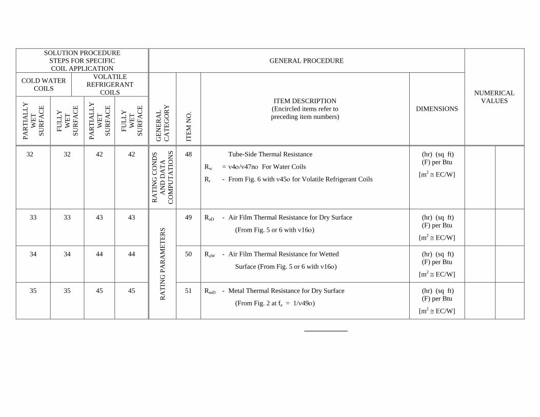
32 32 42 42 R
ATI
NG
CO
ND
S A
ND
DA
TA
CO
MPU
TATI
ON
S 48 Tube-Side Thermal Resistance
Rw = ν4ο/ν47nο For Water Coils
Rr - From Fig. 6 with ν45ο for Volatile Refrigerant Coils
(hr) (sq ft) (F) per Btu
[m2 ≅ ΕC/W]
33 33 43 43 49 RaD - Air Film Thermal Resistance for Dry Surface
(From Fig. 5 or 6 with ν16ο)
(hr) (sq ft) (F) per Btu
[m2 ≅ ΕC/W]
34 34 44 44 50 RaW - Air Film Thermal Resistance for Wetted
Surface (From Fig. 5 or 6 with ν16ο)
(hr) (sq ft) (F) per Btu
[m2 ≅ ΕC/W]
35 35 45 45
RA
TIN
G P
AR
AM
ETER
S
51 RmD - Metal Thermal Resistance for Dry Surface
(From Fig. 2 at fa = 1/ν49ο)
(hr) (sq ft) (F) per Btu
[m2 ≅ ΕC/W]
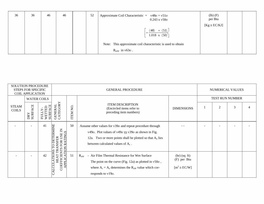
36 36 46 46 52 Approximate Coil Characteristic = ν48ο + ν51ο 0.243 x ν50ο
⎥⎦
⎤⎢⎣
⎡⟩⟨⟩⟨+⟩⟨
=50x018.15148
Note: This approximate coil characteristic is used to obtain
RmW in ν63ο .
(lb) (F) per Btu
[Kg ≅ ΕC/KJ]
SOLUTION PROCEDURE
STEPS FOR SPECIFIC COIL APPLICATION
GENERAL PROCEDURE NUMERICAL VALUES
WATER COILS TEST RUN NUMBER
STEAM COILS
DR
Y
SU
RFA
CE
FULL
Y-
WET
TED
S
UR
FAC
E G
ENER
AL
CA
TEG
OR
Y
ITE
M N
O. ITEM DESCRIPTION
(Encircled items refer to preceding item numbers)
DIMENSIONS 1 2 3 4
- - 41 50 Assume other values for ν39ο and repeat procedure through
ν49ο. Plot values of ν49ο vs ν39ο as shown in Fig.
12a. Two or more points shall be plotted so that Ao lies
between calculated values of Ac .
- - - - - -
- - 42
CA
LCU
LATI
ON
S TO
DET
ERM
INE
HEA
T TR
AN
SFER
C
OEF
FIC
IEN
TS F
OR
USE
IN
APP
LIC
ATI
ON
RA
TIN
GS
51 RaW - Air Film Thermal Resistance for Wet Surface
The point on the curve (Fig. 12a) as plotted in ν50ο ,
where Ac = Ao determines the RaW value which cor-
responds to ν19ο.
(hr) (sq ft) (F) per Btu
[m2 ≅ ΕC/W]
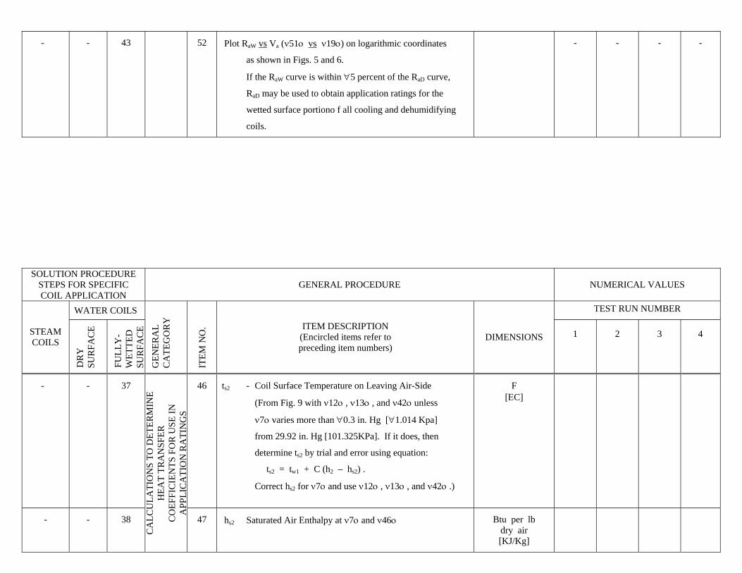
- - 43 52 Plot RaW vs Va (ν51ο vs ν19ο) on logarithmic coordinates
as shown in Figs. 5 and 6.
If the RaW curve is within ∀5 percent of the RaD curve,
RaD may be used to obtain application ratings for the
wetted surface portiono f all cooling and dehumidifying
coils.
- - - -
SOLUTION PROCEDURE
STEPS FOR SPECIFIC COIL APPLICATION
GENERAL PROCEDURE NUMERICAL VALUES
WATER COILS TEST RUN NUMBER
STEAM COILS
DR
Y
SU
RFA
CE
FULL
Y-
WET
TED
S
UR
FAC
E G
ENER
AL
CA
TEG
OR
Y
ITE
M N
O. ITEM DESCRIPTION
(Encircled items refer to preceding item numbers)
DIMENSIONS 1 2 3 4
- - 37 46 ts2 - Coil Surface Temperature on Leaving Air-Side
(From Fig. 9 with ν12ο , ν13ο , and ν42ο unless
ν7ο varies more than ∀0.3 in. Hg [∀1.014 Kpa]
from 29.92 in. Hg [101.325KPa]. If it does, then
determine ts2 by trial and error using equation:
ts2 = tw1 + C (h2 – hs2) .
Correct hs2 for ν7ο and use ν12ο , ν13ο , and ν42ο .)
F [ΕC]
- - 38
CA
LCU
LATI
ON
S TO
DET
ERM
INE
HEA
T TR
AN
SFER
C
OEF
FIC
IEN
TS F
OR
USE
IN
APP
LIC
ATI
ON
RA
TIN
GS
47 hs2 Saturated Air Enthalpy at ν7ο and ν46ο Btu per lb dry air [KJ/Kg]
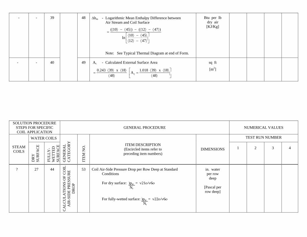
- - 39 48 Δhm - Logarithmic Mean Enthalpy Difference between Air Stream and Coil Surface
⎥⎦
⎤⎢⎣
⎡⟩⟨−⟩⟨⟩⟨−⟩⟨
⟩⟨−⟩⟨−⟩⟨−⟩⟨=
47124510In
)4712()4510(
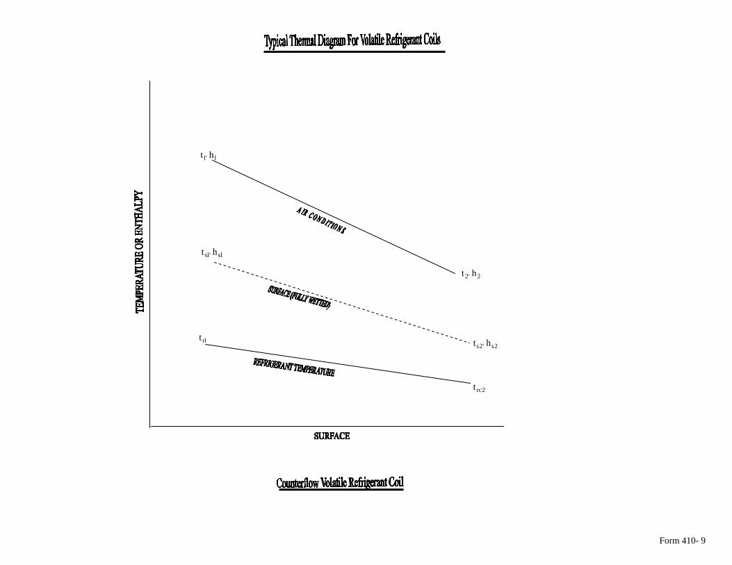
Note: See Typical Thermal Diagram at end of Form.
Btu per lb dry air [KJ/Kg]
- - 40 49 Ac - Calculated External Surface Area
⎥⎦
⎤⎢⎣
⎡⟩⟨
⟩⟨⟩⟨=
⟩⟨⟩⟨⟩⟨
=48
18x39018.1A48
18x39243.0c
sq ft
[m2]
SOLUTION PROCEDURE
STEPS FOR SPECIFIC COIL APPLICATION
GENERAL PROCEDURE NUMERICAL VALUES
WATER COILS TEST RUN NUMBER
STEAM COILS
DR
Y
SU
RFA
CE
FULL
Y-
WET
TED
S
UR
FAC
E G
ENER
AL
CA
TEG
OR
Y
ITE
M N
O. ITEM DESCRIPTION
(Encircled items refer to preceding item numbers)
DIMENSIONS 1 2 3 4
? 27 44
CA
LCU
LATI
ON
S O
F C
OIL
A
IR-S
IDE
PRES
SUR
E D
RO
P
53 Coil Air-Side Pressure Drop per Row Deep at Standard Conditions For dry surface: )pst = ν21ο/ν6ο Nr
For fully-wetted surface: )pst = ν22ο/ν6ο Nr
in. water per row
deep
[Pascal per row deep]
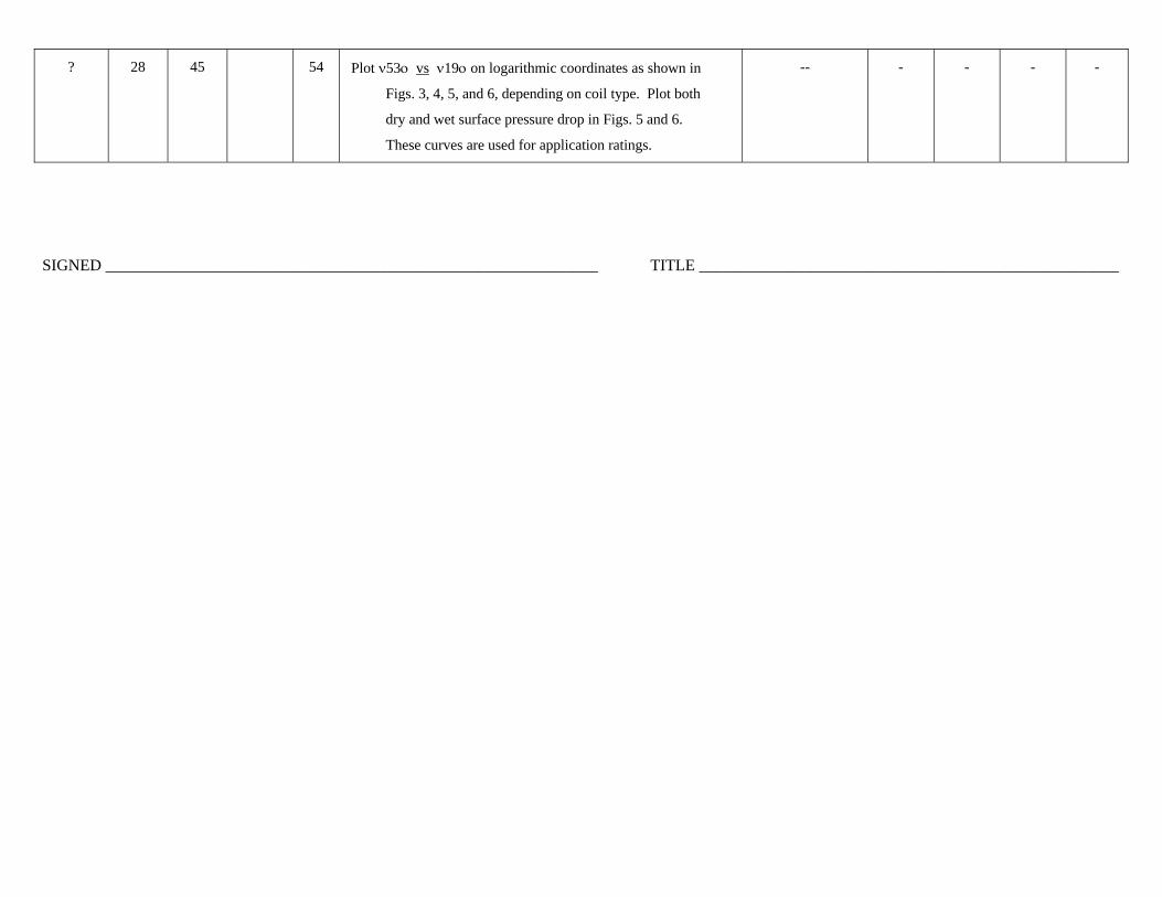
? 28 45 54 Plot ν53ο vs ν19ο on logarithmic coordinates as shown in
Figs. 3, 4, 5, and 6, depending on coil type. Plot both
dry and wet surface pressure drop in Figs. 5 and 6.
These curves are used for application ratings.
-- - - - -
SIGNED _____________________________________________________________ TITLE ____________________________________________________
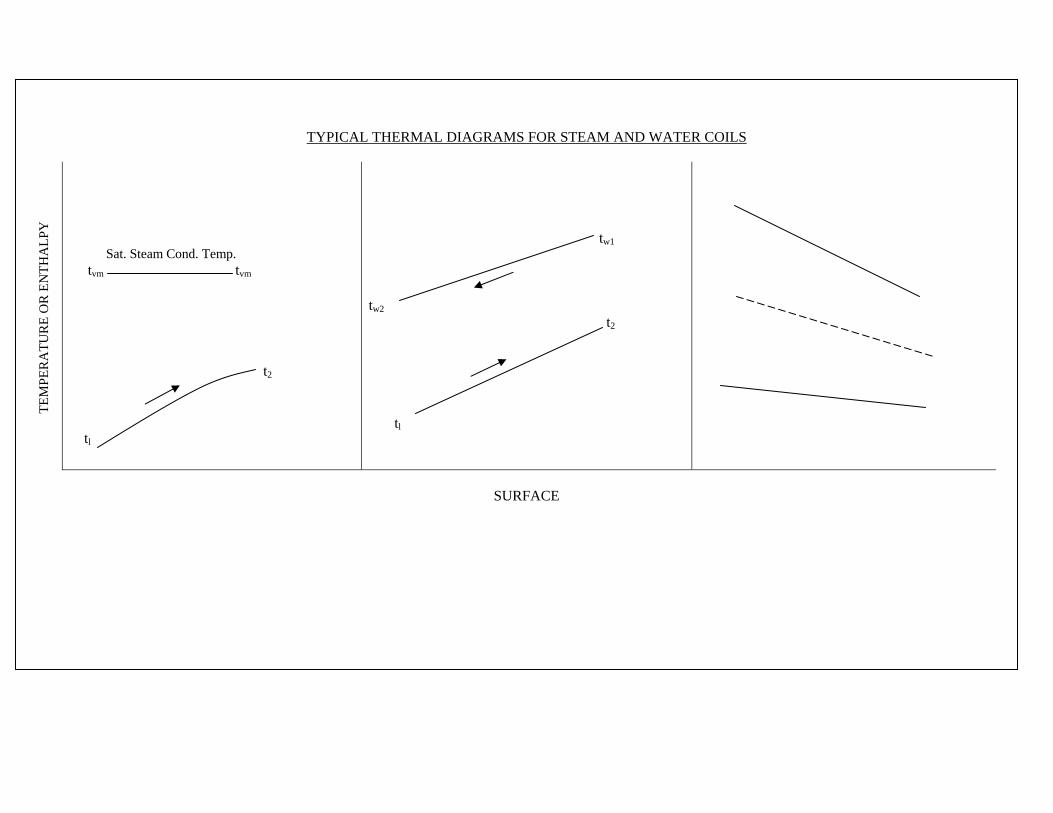
TYPICAL THERMAL DIAGRAMS FOR STEAM AND WATER COILS
Sat. Steam Cond. Temp. tvm tvm t2 tl
tw1 tw2 t2 tl
SURFACE
TEM
PER
ATU
RE
OR
EN
THA
LPY
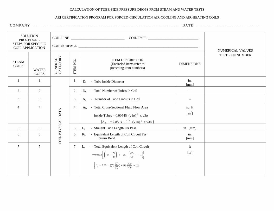
CALCULATION OF TUBE-SIDE PRESSURE DROPS FROM STEAM AND WATER TESTS
ARI CERTIFICATION PROGRAM FOR FORCED-CIRCULATION AIR-COOLING AND AIR-HEATING COILS
COMPANY ____________________________________________________________________ DATE _______________________________
SOLUTION PROCEDURE
STEPS FOR SPECIFIC COIL APPLICATION
COIL LINE _______________________________ COIL TYPE _____________________________ COIL SURFACE _____________________________________________________________________
STEAM COILS
WATER COILS
GEN
ERA
L C
ATE
GO
RY
ITE
M N
O. ITEM DESCRIPTION
(Encircled items refer to preceding item numbers)
DIMENSIONS
NUMERICAL VALUES TEST RUN NUMBER
1 1 1 DI - Tube Inside Diameter in. [mm]
2 2 2 Nt - Total Number of Tubes In Coil --
3 3 3 Nc - Number of Tube Circuits in Coil --
4 4 4 Aix - Total Cross-Sectional Fluid Flow Area Inside Tubes = 0.00545 (ν1ο) 2 x ν3ο
[Aix = 7.85 x 10- 7 (ν1ο) 2 x ν3ο ]
sq ft
[m2]
5 5 5 Lx - Straight Tube Length Per Pass in. [mm]
6 6 6 Kb - Equivalent Length of Coil Circuit Per Return Bend
in. [mm]
7 7
CO
IL P
HY
SIC
AL
DA
TA
Le - Total Equivalent Length of Coil Circuit
⎥⎦
⎤⎢⎣
⎡⎟⎟⎠
⎞⎜⎜⎝
⎛−
⟩⟨⟩⟨
⟩⟨+⎟⎟⎠
⎞⎜⎜⎝
⎛⟩⟨⟩⟨
⟩⟨= 1326
3250833.0
⎥⎦
⎤⎢⎣
⎡−
⟩⟨⟩⟨
⟩⟨+⟩⟨⟩⟨
⟩⟨= )]132(6)
325[001.0Le
ft 7
[m]
SOLUTION PROCEDURE STEPS FOR SPECIFIC COIL APPLICATION
GENERAL PROCEDURE NUMERICAL VALUES
TEST RUN NUMBER
STEAM COILS WATER
COILS
GEN
ERA
L C
ATE
GO
RY
ITE
M N
O. ITEM DESCRIPTION
(Encircled items refer to preceding item numbers)
DIMENSIONS 1 2 3 4
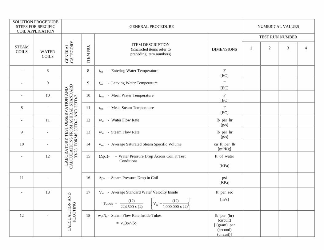
- 8 8 tw1 - Entering Water Temperature F [ΕC]
- 9 9 tw2 - Leaving Water Temperature F [ΕC]
- 10 10 twm - Mean Water Temperature F [ΕC]
8 - 11 tvm - Mean Steam Temperature F [ΕC]
- 11 12 ww - Water Flow Rate lb per hr [g/s]
9 - 13 ww - Steam Flow Rate lb per hr [g/s]
10 - 14 vvm - Average Saturated Steam Specific Volume cu ft per lb [m3/Kg]
- 12 15 (∆pw)T - Water Pressure Drop Across Coil at Test Conditions
ft of water
[KPa]
11 -
LAB
OR
ATO
RY
TES
T O
BSE
RV
ATI
ON
AN
D
CA
LCU
LATI
ON
S FR
OM
ASH
RA
E ST
AN
DA
RD
33
-78
FO
RM
S 33
TD-2
AN
D 3
3TD
-3
16 ∆pv - Steam Pressure Drop in Coil psi [KPa]
- 13 17 Vw - Average Standard Water Velocity Inside
Tubes = ⎥⎦
⎤⎢⎣
⎡⟩⟨
⟩⟨=
⟩⟨⟩⟨
4x000,000,112V
4x500,22412
w
ft per sec
[m/s]
12 -
CA
LCU
ALT
ION
AN
D
PLO
TTIN
G
18 wv/Nc - Steam Flow Rate Inside Tubes
= ν13ο/ν3ο
lb per (hr) (circuit)
[ (gram) per (second) (circuit)]
SOLUTION PROCEDURE STEPS FOR SPECIFIC COIL APPLICATION
GENERAL PROCEDURE NUMERICAL VALUES
TEST RUN NUMBER
STEAM COILS WATER
COILS G
ENER
AL
CA
TEG
OR
Y
ITE
M N
O. ITEM DESCRIPTION
(Encircled items refer to preceding item numbers)
DIMENSIONS 1 2 3 4
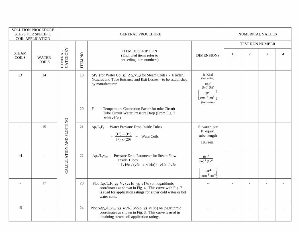
19 ∆Ph (for Water Coils); ∆ph/vvm (for Steam Coils) - Header, Nozzles and Tube Entrance and Exit Losses – to be established by manufacturer
ft [KPa] (for water)
(lb)2
(In.)2 (ft)3
⎥⎥
⎦
⎤
⎢⎢
⎣
⎡
3)m(2)mm(
2)g(
(for steam)
13 14
20 Ft - Temperature Coorection Factor for tube Circuit Tube Circuit Water Pressure Drop (From Fig. 7 with ν10ο)
- 15 21 ∆pt/LeFt - Water Pressure Drop Inside Tubes
= WaterCoils20x71915
−⟩⟨⟩⟨⟩⟨−⟩⟨
ft water per ft equiv.
tube length
[KPa/m]
14 - 22 ∆ptv/Levvm - Pressure Drop Parameter for Steam Flow Inside Tubes = [ν16ο / (ν7ο x ν14ο)] - ν19ο / ν7ο
⎥⎥
⎦
⎤
⎢⎢
⎣
⎡
4)m(2)mm(
2)g(
4)ft(2.)in(
2)lb(
CA
LCU
LATI
ON
AN
D P
LOTT
ING
- 17 23 Plot ∆pt/LeFt vs Vw (ν21ο vs ν17ο) on logarithmic coordinates as shown in Fig. 4. This curve with Fig. 7 is sued for application ratings for either cold water or hot water coils.
-- - - - -
15 - 24 -- - - - - Plot Δ∆ptv/Levvm vs wv/Nc (ν22ο vs ν18ο) on logarithmic coordinates as shown in Fig. 3. This curve is used in obtaining steam coil application ratings.

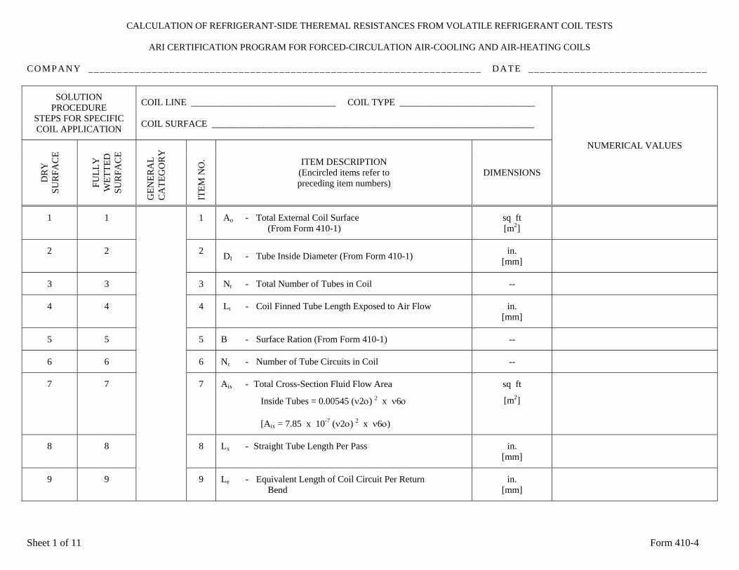
CALCULATION OF REFRIGERANT-SIDE THEREMAL RESISTANCES FROM VOLATILE REFRIGERANT COIL TESTS
ARI CERTIFICATION PROGRAM FOR FORCED-CIRCULATION AIR-COOLING AND AIR-HEATING COILS
COMPANY ____________________________________________________________________ DATE _______________________________
SOLUTION PROCEDURE
STEPS FOR SPECIFIC COIL APPLICATION
COIL LINE _______________________________ COIL TYPE _____________________________ COIL SURFACE _____________________________________________________________________
DR
Y
SUR
FAC
E
FU
LLY
W
ETTE
D
SUR
FAC
E G
ENER
AL
CA
TEG
OR
Y
ITE
M N
O. ITEM DESCRIPTION
(Encircled items refer to preceding item numbers)
DIMENSIONS NUMERICAL VALUES
1 1 1 Ao - Total External Coil Surface (From Form 410-1)
sq ft [m2]
2 2 2 DI - Tube Inside Diameter (From Form 410-1) in. [mm]
3 3 3 Nt - Total Number of Tubes in Coil --
4 4 4 Lt - Coil Finned Tube Length Exposed to Air Flow in. [mm]
5 5 5 B - Surface Ration (From Form 410-1) --
6 6 6 Nc - Number of Tube Circuits in Coil --
7 7 7 Aix - Total Cross-Section Fluid Flow Area
Inside Tubes = 0.00545 (ν2ο) 2 x ν6ο
[Aix = 7.85 x 10⁻⁷ (ν2ο) 2 x ν6ο)
sq ft
[m2]
8 8 8 Lx - Straight Tube Length Per Pass in. [mm]
9 9
9 Le - Equivalent Length of Coil Circuit Per Return Bend
in. [mm]
Sheet 1 of 11 Form 410-4
SOLUTION PROCEDURE
STEPS FOR SPECIFIC COIL APPLICATION
GENERAL PROCEDURE NUMERICAL VALUES
TEST RUN NUMBER
DR
Y
SUR
FAC
E
FULL
Y
WET
TED
SU
RFA
CE
GEN
ERA
L C
ATE
GO
RY
ITE
M N
O. ITEM DESCRIPTION
(Encircled items refer to preceding item numbers)
DIMENSIONS 1 2 3 4
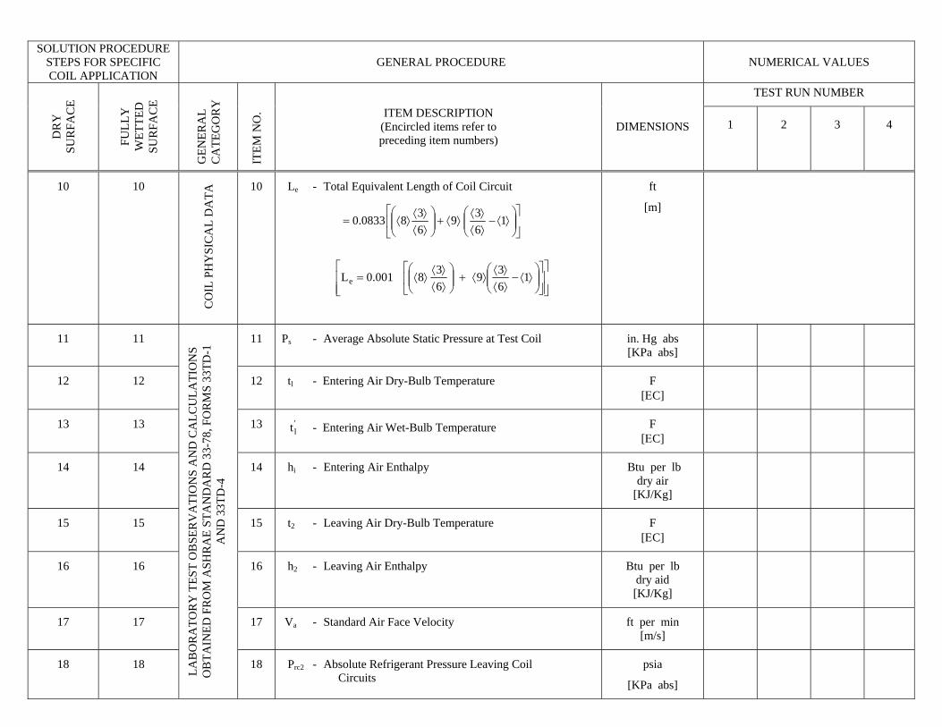
10 10 10
Le - Total Equivalent Length of Coil Circuit
ft
CO
IL P
HY
SIC
AL
DA
TA
[m]
11 11 11 Ps - Average Absolute Static Pressure at Test Coil in. Hg abs [KPa abs]
⎥⎦
⎤⎢⎣
⎡⎟⎟⎠
⎞⎜⎜⎝
⎛⟩⟨−
⟩⟨⟩⟨
⟩⟨+⎟⎟⎠
⎞⎜⎜⎝
⎛⟩⟨⟩⟨
⟩⟨= 1639
6380833.0
⎥⎥⎦
⎤
⎢⎢⎣
⎡⎥⎦
⎤⎢⎣
⎡⎟⎟⎠
⎞⎜⎜⎝
⎛⟩⟨−
⟩⟨⟩⟨
⟩⟨+⎟⎟⎠
⎞⎜⎜⎝
⎛⟩⟨⟩⟨
⟩⟨= 1639
638001.0Le
12 12 12 tl - Entering Air Dry-Bulb Temperature F [ΕC]
13 13 13 'lt - Entering Air Wet-Bulb Temperature
F [ΕC]
14 14 14 hi - Entering Air Enthalpy
Btu per lb dry air
[KJ/Kg]
15 15 15 t2 - Leaving Air Dry-Bulb Temperature F [ΕC]
16 16 16 h2 - Leaving Air Enthalpy Btu per lb dry aid [KJ/Kg]
17 17 17 Va - Standard Air Face Velocity ft per min [m/s]
18 18
LAB
OR
ATO
RY
TES
T O
BSE
RV
ATI
ON
S A
ND
CA
LCU
LATI
ON
S O
BTA
INED
FR
OM
ASH
RA
E ST
AN
DA
RD
33-
78, F
OR
MS
33TD
-1
AN
D 3
3TD
-4
18 Prc2 - Absolute Refrigerant Pressure Leaving Coil Circuits
psia
[KPa abs]
SOLUTION PROCEDURE STEPS FOR SPECIFIC COIL APPLICATION
GENERAL PROCEDURE NUMERICAL VALUES
TEST RUN NUMBER
DR
Y
SUR
FAC
E
FULL
Y
WET
TED
SU
RFA
CE
GEN
ERA
L C
ATE
GO
RY
ITE
M N
O. ITEM DESCRIPTION
(Encircled items refer to preceding item numbers)
DIMENSIONS 1 2 3 4
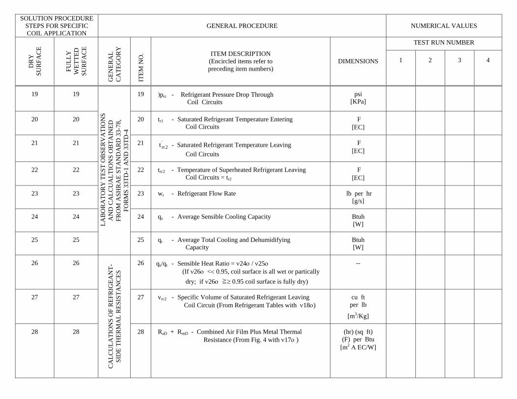
19 19 19 )prc - Refrigerant Pressure Drop Through Coil Circuits
psi [KPa]
20 20 20 tr1 - Saturated Refrigerant Temperature Entering Coil Circuits
F [ΕC]
21 21 21 - Saturated Refrigerant Temperature Leaving '2rct
Coil Circuits
F [ΕC]
22 22 22 trc2 - Temperature of Superheated Refrigerant Leaving Coil Circuits = tr2
F [ΕC]
23 23 23 wr - Refrigerant Flow Rate
lb per hr [g/s]
24 24 24 qs - Average Sensible Cooling Capacity Btuh [W]
25 25
LA
BO
RA
TOR
Y T
EST
OB
SER
VA
TIO
NS
AN
D C
ALC
UA
LTIO
NS
OB
TAIN
ED
FRO
M A
SHR
AE
STA
ND
AR
D 3
3-78
, FO
RM
S 33
TD-1
AN
D 3
3TD
-4
25 qt - Average Total Cooling and Dehumidifying Capacity
Btuh [W]
26 26 26 qs/qt - Sensible Heat Ratio = ν24ο / ν25ο (If ν26ο << 0.95, coil surface is all wet or partically dry; if ν26ο ≧≥ 0.95 coil surface is fully dry)
--
27 27 27 vrc2 - Specific Volume of Saturated Refrigerant Leaving Coil Circuit (From Refrigerant Tables with ν18ο)
cu ft per lb
[m3/Kg]
28 28
CA
LCU
LATI
ON
S O
F R
EFR
IGEA
NT-
SID
E TH
ERM
AL
RES
ISTA
NC
ES
28 RaD + RmD - Combined Air Film Plus Metal Thermal Resistance (From Fig. 4 with ν17ο )
(hr) (sq ft) (F) per Btu
[m2 Α ΕC/W]

FORM 410-4
SOLUTION PROCEDURE
STEPS FOR SPECIFIC COIL APPLICATION
GENERAL PROCEDURE NUMERICAL VALUES
TEST RUN NUMBER
DR
Y
SUR
FAC
E
FULL
Y
WET
TED
SU
RFA
CE
GEN
ERA
L C
ATE
GO
RY
ITE
M N
O. ITEM DESCRIPTION
(Encircled items refer to preceding item numbers)
DIMENSIONS 1 2 3 4
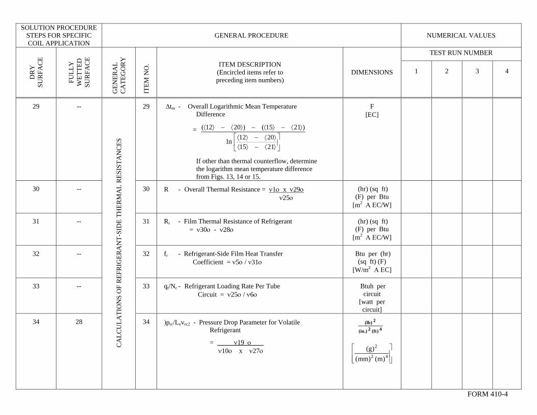
29 -- 29 ∆tm - Overall Logarithmic Mean Temperature Difference = If other than thermal counterflow, determine the logarithm mean temperature difference from Figs. 13, 14 or 15.
F [ΕC]
30 -- 30 R - Overall Thermal Resistance = ν1ο x ν29ο ν25ο
(hr) (sq ft) (F) per Btu
[m2 Α ΕC/W]
⎥⎦
⎤⎢⎣
⎡⟩⟨−⟩⟨⟩⟨−⟩⟨
⟩⟨−⟩⟨−⟩⟨−⟩⟨
21152012n1
)2115()2012(
31 -- 31 Rr - Film Thermal Resistance of Refrigerant = ν30ο - ν28ο
(hr) (sq ft) (F) per Btu
[m2 Α ΕC/W]
32 -- 32 fr - Refrigerant-Side Film Heat Transfer Coefficient = ν5ο / ν31ο
Btu per (hr) (sq ft) (F)
[W/m2 Α ΕC]
33 -- 33 qt/Nc - Refrigerant Loading Rate Per Tube Circuit = ν25ο / ν6ο
Btuh per circuit
[watt per circuit]
34 28
CA
LCU
LATI
ON
S O
F R
EFR
IGER
AN
T-SI
DE
THER
MA
L R
ESIS
TAN
CES
34 )prc/Levrc2 - Pressure Drop Parameter for Volatile Refrigerant
= ν19 ο ν10ο x ν27ο
⎥⎥⎦
⎤
⎢⎢⎣
⎡42
2
)m()mm()g(
FORM 410-4
2)lb(4)ft(2.)in(

SOLUTION PROCEDURE STEPS FOR SPECIFIC COIL APPLICATION
GENERAL PROCEDURE NUMERICAL VALUES
TEST RUN NUMBER
DR
Y
SUR
FAC
E
FULL
Y
WET
TED
SU
RFA
CE
GEN
ERA
L C
ATE
GO
RY
ITEM DESCRIPTION (Encircled items refer to preceding item numbers)
DIMENSIONS 1
ITE
M N
O.
2 3 4
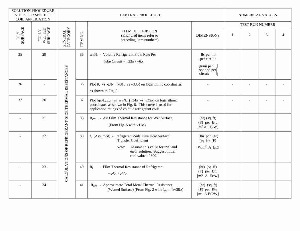
35 29 35 wr/Nc - Volatile Refrigerant Flow Rate Per
Tube Circuit = ν23ο / ν6ο
lb per hr per circuit
⎥⎥⎦
⎤
⎢⎢⎣
⎡
circuitperondsec
pergram
36 - 36 Plot Rr vs qt/Nc (ν31ο vs ν33ο) on logarithmic coordinates
as shown in Fig. 6.
-- - - - -
37 30 37 Plot Δpc/Levrc2 vs wr/Nc (ν34ο vs ν35ο) on logarithmic coordinates as shown in Fig. 6. This curve is used for application ratings of volatile refrigerant coils.
-- - - - -
- 31 38 RaW - Air Film Thermal Resistance for Wet Surface
(From Fig. 5 with ν17ο)
(hr) (sq ft) (F) per Btu [m2 Α ΕC/W]
32 39 fr (Assumed) - Refrigerant-Side Film Heat Surface Transfer Coefficient
Note: Assume this value for trial and error solution. Suggest initial trial value of 300.
Btu per (hr) (sq ft) (F)
[W/m2 Α ΕC]
-
- 33 40 Rr - Film Thermal Resistance of Refrigerant
= ν5ο / ν39ο
(hr) (sq ft) (F) per Btu
[m2 Α Εc/w]
- 34
CA
LCU
LATI
ON
S O
F R
EFR
IGER
AN
T-SI
DE
THER
MA
L R
ESIS
TAN
CES
41 RmW - Approximate Total Metal Thermal Resistance (Wetted Surface) (From Fig. 2 with faW = 1/ν38ο)
(hr) (sq ft) (F) per Btu
[m2 Α ΕC/W]
FORM 410-4 SOLUTION PROCEDURE
STEPS FOR SPECIFIC COIL APPLICATION
GENERAL PROCEDURE NUMERICAL VALUES
TEST RUN NUMBER
DR
Y
SUR
FAC
E
FULL
Y
WET
TED
SU
RFA
CE
GEN
ERA
L C
ATE
GO
RY
ITEM DESCRIPTION (Encircled items refer to preceding item numbers)
DIMENSIONS 1 2 3 4
ITE
M N
O.
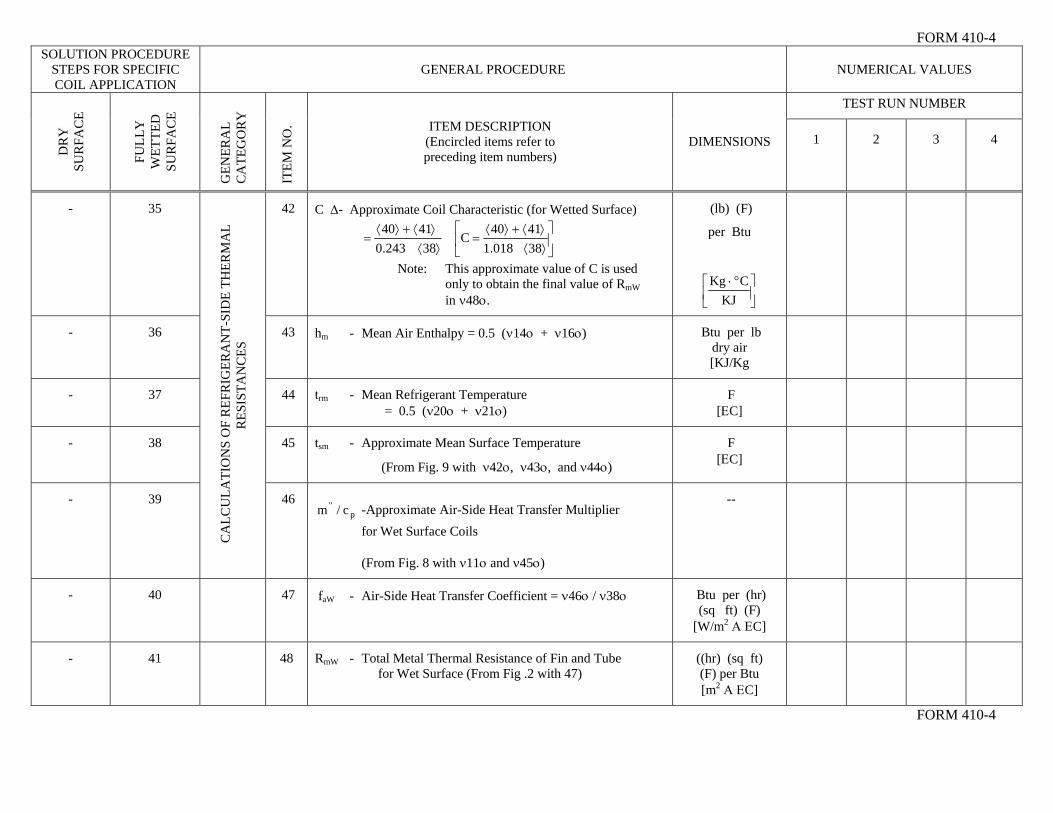
- 35 42 C Δ- Approximate Coil Characteristic (for Wetted Surface)
⎥⎦
⎤⎢⎣
⎡⟩⟨⟩⟨+⟩⟨
=⟩⟨⟩⟨+⟩⟨
=38018.14140
C38243.0
4140
Note: This approximate value of C is used only to obtain the final value of RmW
in ν48ο.
(lb) (F)
per Btu
⎥⎦
⎤⎢⎣
⎡ °⋅KJ
CKg
- 36 43 hm - Mean Air Enthalpy = 0.5 (ν14ο + ν16ο) Btu per lb dry air [KJ/Kg
- 37 44 trm - Mean Refrigerant Temperature = 0.5 (ν20ο + ν21ο)
F [ΕC]
- 38 45 tsm - Approximate Mean Surface Temperature
(From Fig. 9 with ν42ο, ν43ο, and ν44ο)
F [ΕC]
- 39
CA
LCU
LATI
ON
S O
F R
EFR
IGER
AN
T-SI
DE
THER
MA
L R
ESIS
TAN
CES
46
p" c/m -Approximate Air-Side Heat Transfer Multiplier
for Wet Surface Coils (From Fig. 8 with ν11ο and ν45ο)
--
- 40 47 faW - Air-Side Heat Transfer Coefficient = ν46ο / ν38ο Btu per (hr) (sq ft) (F)
[W/m2 Α ΕC]
- 41 48 RmW - Total Metal Thermal Resistance of Fin and Tube for Wet Surface (From Fig .2 with 47)
((hr) (sq ft) (F) per Btu [m2 Α ΕC]
FORM 410-4
SOLUTION PROCEDURE STEPS FOR SPECIFIC COIL APPLICATION
GENERAL PROCEDURE NUMERICAL VALUES
TEST RUN NUMBER
DR
Y
SUR
FAC
E
FULL
Y
WET
TED
SU
RFA
CE
GEN
ERA
L C
ATE
GO
RY
ITE
M N
O. ITEM DESCRIPTION
(Encircled items refer to preceding item numbers)
DIMENSIONS 1 2 3 4
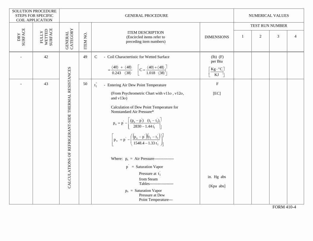
- 42 49 C - Coil Charactertistic for Wetted Surface
⟩⟨⟩⟨+⟩⟨
=38243.04840
⎥⎦
⎤⎢⎣
⎡⟩⟨⟩⟨+⟩⟨
=38018.14840C
(lb) (F) per Btu
⎥⎦
⎤⎢⎣
⎡ °⋅KJ
CKg
- 43
CA
LCU
LATI
ON
S O
F R
EFR
IGER
AN
T-SI
DE
THER
MA
L R
ESIS
TAN
CES
50 "lt - Entering Air Dew Point Temperature
(From Psychrometric Chart with ν11ο , ν12ο, and ν13ο) Calculation of Dew Point Temperature for Nonstandard Air Pressure*
⎥⎥⎦
⎤
⎢⎢⎣
⎡
−−−
−= 'l
'll
's'
v t44.12830)tt()pp(pp
( ) ( )
⎥⎥⎦
⎤
⎢⎢⎣
⎡⎟⎟⎠
⎞⎜⎜⎝
⎛
−
−−−=
'l
'll
's'
vt33.14.1548ttpp
pp
Where: ps = Air Pressure---------------
= Saturation Vapor 'p
Pressure at 'lt
from Steam Tables------------------
pv = Saturation Vapor
F
[ΕC]
Pressure at Dew Point Temperature---
in. Hg abs
{Kpa abs]
FORM 410-4
SOLUTION PROCEDURE STEPS FOR SPECIFIC COIL APPLICATION
GENERAL PROCEDURE NUMERICAL VALUES
TEST RUN NUMBER
DR
Y
SUR
FAC
E
FULL
Y
WET
TED
SU
RFA
CE
GEN
ERA
L C
ATE
GO
RY
ITE
M N
O. ITEM DESCRIPTION
(Encircled items refer to preceding item numbers)
DIMENSIONS 1 2 3 4
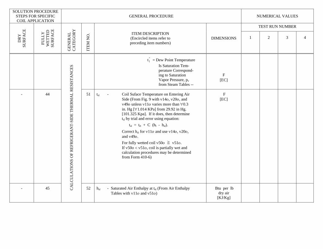
= Dew Point Temperature "lt
Is Saturation Tem- perature Correspond- ing to Saturation Vapor Pressure, pv from Steam Tables --
F [ΕC]
- 44 51 tsl - Coil Suface Temperature on Entering Air Side (From Fig. 9 with ν14ο, ν20ο, and ν49ο unless ν11ο varies more than ∀0.3 in. Hg [∀1.014 KPa] from 29.92 in Hg. [101.325 Kpa]. If it does, then determine tsl by trial and error using equation: tsl = trl + C (hl - hsl). Correct hsl for ν11ο and use ν14ο, ν20ο, and ν49ο. For fully wetted coil ν50ο ≧ ν51ο. If ν50ο < ν51ο, coil is partially wet and calculation procedures may be determined from Form 410-6)
F [ΕC]
- 45 CA
LCU
LATI
ON
S O
F R
EFR
IGER
AN
T-SI
DE
THER
MA
L R
ESIS
TAN
CES
52 hsl - Saturated Air Enthalpy at tsl (From Air Enthalpy Btu per lb dry air
[KJ/Kg]
Tables with ν11ο and ν51ο)
FORM 410-4 SOLUTION PROCEDURE
STEPS FOR SPECIFIC COIL APPLICATION
GENERAL PROCEDURE NUMERICAL VALUES
TEST RUN NUMBER
DR
Y
SUR
FAC
E
FULL
Y
WET
TED
SU
RFA
CE
GEN
ERA
L C
ATE
GO
RY
ITE
M N
O. ITEM DESCRIPTION
(Encircled items refer to preceding item numbers)
DIMENSIONS 1 2 3 4
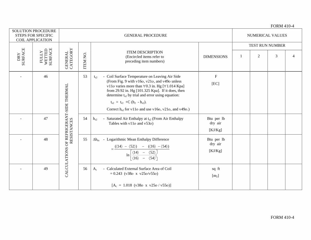
- 46 53 ts2 - Coil Surface Temperature on Leaving Air Side (From Fig. 9 with ν16ο, ν21ο, and ν49ο unless ν11ο varies more than ∀0.3 in. Hg [∀1.014 Kpa] from 29.92 in. Hg [101.325 Kpa]. If it does, then determine ts2 by trial and error using equation:
ts2 = tr2 +C (h2 - hs2).
Correct hs2 for ν11ο and use ν16ο, ν21ο, and ν49ο.)
F
[ΕC]
- 47 54 hs2 - Saturated Air Enthalpy at ts2 (From Air Enthalpy Tables with ν11ο and ν53ο)
Btu per lb dry air
[KJ/Kg]
- 48 55 ∆hm - Logarithmic Mean Enthalpy Difference
⎥⎦
⎤⎢⎣
⎡⟩⟨−⟩⟨⟩⟨−⟩⟨
⟩⟨−⟩⟨−⟩⟨−⟩⟨=
54165214
ln
)5416()5214(
Btu per lb dry air
[KJ/Kg]
- 49
CA
LCU
LATI
ON
S O
F R
EFR
IGER
AN
T-SI
DE
THER
MA
L R
ESIS
TAN
CES
sq ft 56 Ac - Calculated External Surface Area of Coil = 0.243 (ν38ο x ν25ο/ν55ο)
[Ac = 1.018 (ν38ο x ν25ο / ν55ο)]
[m2]
FORM 410-4
SOLUTION PROCEDURE
STEPS FOR SPECIFIC COIL APPLICATION
GENERAL PROCEDURE NUMERICAL VALUES
TEST RUN NUMBER
DR
Y
SUR
FAC
E
FULL
Y
WET
TED
SU
RFA
CE
GEN
ERA
L C
ATE
GO
RY
ITE
M N
O. ITEM DESCRIPTION
(Encircled items refer to preceding item numbers)
DIMENSIONS 1 2 3 4
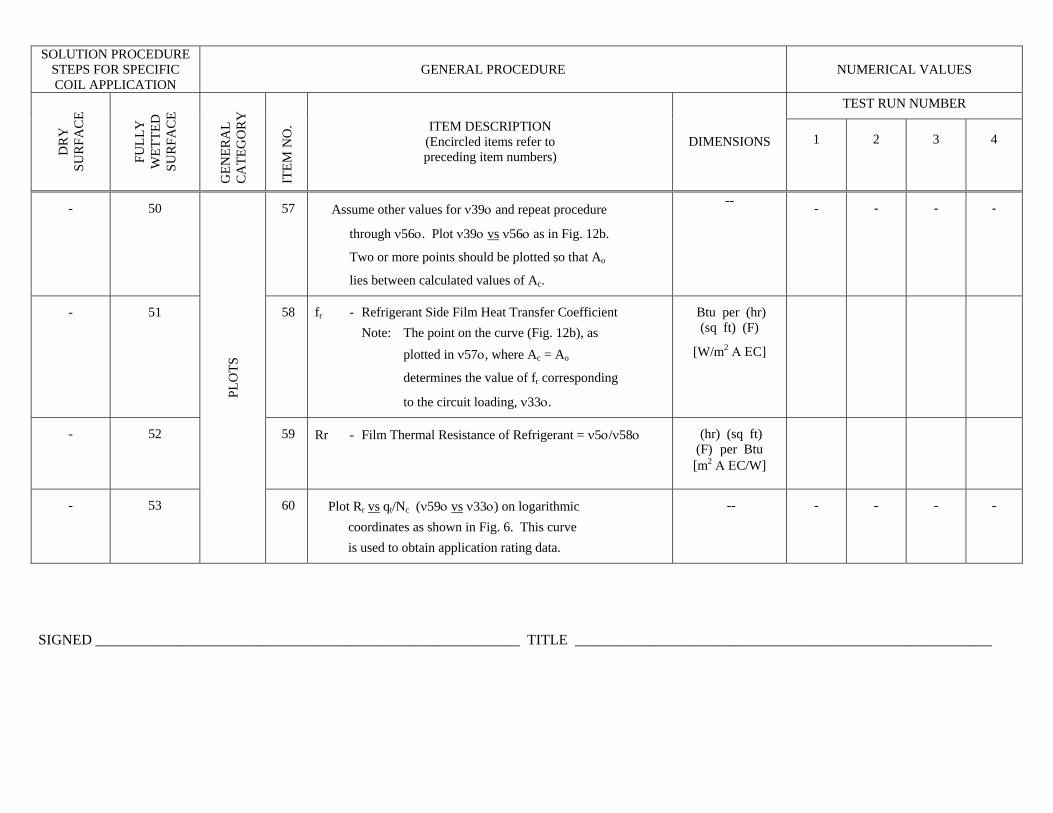
- 50 57 Assume other values for ν39ο and repeat procedure
through ν56ο. Plot ν39ο vs ν56ο as in Fig. 12b.
Two or more points should be plotted so that Ao
lies between calculated values of Ac.
-- - - - -
- 51 58 fr - Refrigerant Side Film Heat Transfer Coefficient Note: The point on the curve (Fig. 12b), as plotted in ν57ο, where Ac = Ao
determines the value of fr corresponding
to the circuit loading, ν33ο.
Btu per (hr) (sq ft) (F)
[W/m2 Α ΕC]
- 52 59 Rr - Film Thermal Resistance of Refrigerant = ν5ο/ν58ο
(hr) (sq ft) (F) per Btu [m2 Α ΕC/W]
- 53
PLO
TS
60 Plot Rr vs qt/Nc (ν59ο vs ν33ο) on logarithmic coordinates as shown in Fig. 6. This curve is used to obtain application rating data.
-- - - - -
SIGNED __________________________________________________________ TITLE _________________________________________________________
Form 410- 9
sl'sl ht
rlt
l'l ht
2'2 ht
2s'2s ht
2rct
Form 4 0- 9 1
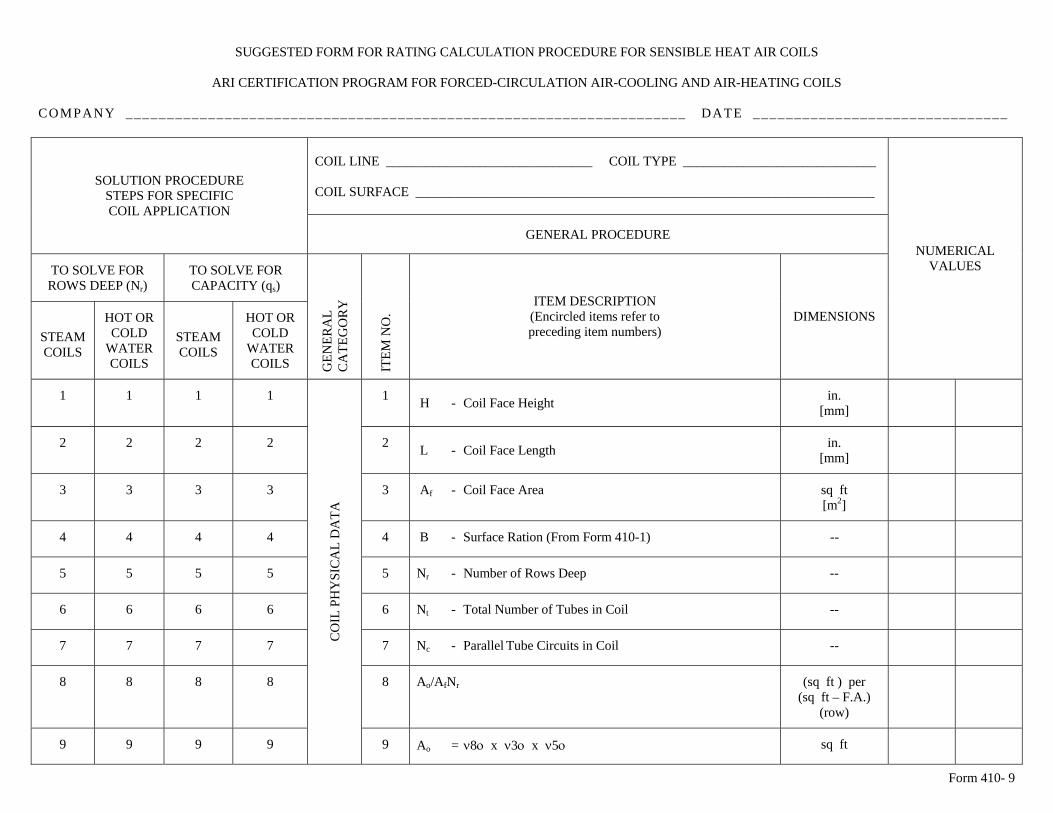
SUGGESTED FORM FOR RATING CALCULATION PROCEDURE FOR SENSIBLE HEAT AIR COILS
ARI CERTIFICATION PROGRAM FOR FORCED-CIRCULATION AIR-COOLING AND AIR-HEATING COILS
COMPANY ____________________________________________________________________ DATE _______________________________
COIL LINE _______________________________ COIL TYPE _____________________________ COIL SURFACE _____________________________________________________________________
SOLUTION PROCEDURE STEPS FOR SPECIFIC COIL APPLICATION
GENERAL PROCEDURE
TO SOLVE FOR ROWS DEEP (Nr)
TO SOLVE FOR CAPACITY (qs)
STEAM COILS
HOT OR COLD
WATER COILS
STEAM COILS
HOT OR COLD
WATER COILS
GEN
ERA
L C
ATE
GO
RY
ITE
M N
O.
ITEM DESCRIPTION (Encircled items refer to preceding item numbers)
DIMENSIONS
NUMERICAL VALUES
1 1 1 1 1 H - Coil Face Height in. [mm]
2 2 2 2 2 L - Coil Face Length in.
[mm]
3 3 3 3 3 Af - Coil Face Area sq ft [m2]
4 4 4 4 4 B - Surface Ration (From Form 410-1) -- 5 5 5 5 5 Nr - Number of Rows Deep -- 6 6 6 6 6 Nt - Total Number of Tubes in Coil -- 7 7 7 7 7 Nc - Parallel Tube Circuits in Coil -- 8 8 8 8 8 Ao/AfNr (sq ft ) per
(sq ft – F.A.) (row)
9 9 9 9
CO
IL P
HY
SIC
AL
DA
TA
9 Ao = ν8ο x ν3ο x ν5ο sq ft
Form 410- 9
10 10 10 10 10 Di - Tube Inside Diameter
in. [mm]
COIL LINE _______________________________ COIL TYPE _____________________________ COIL SURFACE _____________________________________________________________________
SOLUTION PROCEDURE STEPS FOR SPECIFIC COIL APPLICATION
GENERAL PROCEDURE
TO SOLVE FOR ROWS DEEP (Nr)
TO SOLVE FOR CAPACITY (qs)
STEAM COILS
HOT OR COLD
WATER COILS
STEAM COILS
HOT OR COLD
WATER COILS
GEN
ERA
L C
ATE
GO
RY
ITE
M N
O.
ITEM DESCRIPTION (Encircled items refer to preceding item numbers)
DIMENSIONS
NUMERICAL VALUES
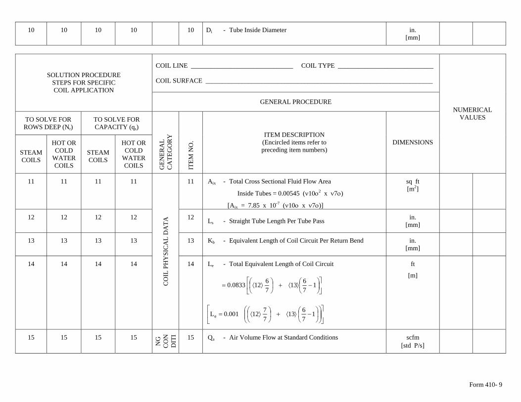
11 11 11 11 11 Aix - Total Cross Sectional Fluid Flow Area
Inside Tubes = 0.00545 (ν10ο2 x ν7ο)
[Aix = 7.85 x 10⁻⁷ (ν10ο x ν7ο)]
sq ft [m2]
12 12 12 12 12 Ls - Straight Tube Length Per Tube Pass in. [mm]
13 13 13 13 13 Kb - Equivalent Length of Coil Circuit Per Return Bend in.
[mm]
14 14 14 14
CO
IL P
HY
SIC
AL
DA
TA
14 Le - Total Equivalent Length of Coil Circuit
⎥⎦
⎤⎢⎣
⎡⎟⎠⎞
⎜⎝⎛ −⟩⟨+⎟
⎠⎞
⎜⎝⎛ ⟩⟨= 1
7613
76120833.0
⎥⎦
⎤⎢⎣
⎡⎟⎟⎠
⎞⎜⎜⎝
⎛⎟⎠⎞
⎜⎝⎛ −⟩⟨+⎟
⎠⎞
⎜⎝⎛ ⟩⟨= 1
7613
7712001.0Le
ft
[m]
15 15 15 15
NG
C
ON
DIT
I 15 Qa - Air Volume Flow at Standard Conditions scfm [std Ρ/s]
Form 410- 9
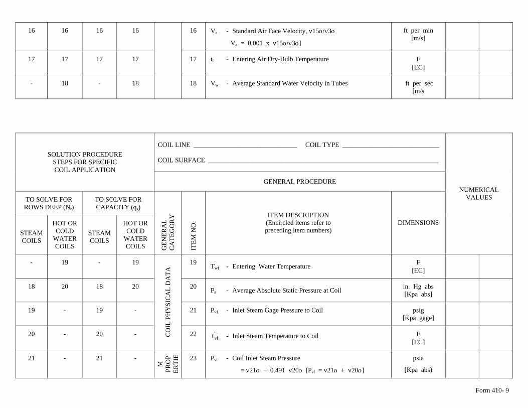
16 16 16 16 16 Va - Standard Air Face Velocity, ν15ο/ν3ο
Va = 0.001 x ν15ο/ν3ο]
ft per min [m/s]
17 17 17 17 17 tl - Entering Air Dry-Bulb Temperature F [ΕC]
- 18 - 18 18 Vw - Average Standard Water Velocity in Tubes ft per sec
[m/s
COIL LINE _______________________________ COIL TYPE _____________________________ COIL SURFACE _____________________________________________________________________
SOLUTION PROCEDURE STEPS FOR SPECIFIC COIL APPLICATION
GENERAL PROCEDURE
TO SOLVE FOR ROWS DEEP (Nr)
TO SOLVE FOR CAPACITY (qs)
STEAM COILS
HOT OR COLD
WATER COILS
STEAM COILS
HOT OR COLD
WATER COILS
GEN
ERA
L C
ATE
GO
RY
ITE
M N
O.
ITEM DESCRIPTION (Encircled items refer to preceding item numbers)
DIMENSIONS
NUMERICAL VALUES
- 19 - 19 19 Twl - Entering Water Temperature F [ΕC]
18 20 18 20 20 Ps - Average Absolute Static Pressure at Coil in. Hg abs
[Kpa abs]
19 - 19 - 21 Pv1 - Inlet Steam Gage Pressure to Coil psig [Kpa gage]
20 - 20 - C
OIL
PH
YSI
CA
L D
ATA
22 - Inlet Steam Temperature to Coil 'vlt F
[ΕC]
21 - 21 -
SM
PR
OP
ERTI
E 23 Pvl - Coil Inlet Steam Pressure
= ν21ο + 0.491 ν20ο [Pvl = ν21ο + ν20ο]
psia
[Kpa abs)
Form 410- 9
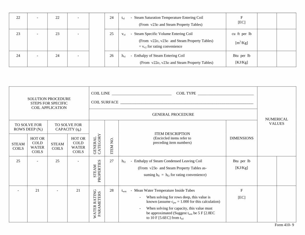
22 - 22 - 24 tvl - Steam Saturation Temperature Entering Coil
(From ν23ο and Steam Property Tables)
F [ΕC]
23 - 23 - 25 vvl - Steam Specific Volume Entering Coil
(From ν22ο, ν23ο and Steam Property Tables) = vv2 for rating convenience
cu ft per lb
[m3/Kg]
24 - 24 - 26 hvl - Enthalpy of Steam Entering Coil
(From ν22ο, ν23ο and Steam Property Tables)
Btu per lb
[KJ/Kg]
COIL LINE _______________________________ COIL TYPE _____________________________ COIL SURFACE _____________________________________________________________________
SOLUTION PROCEDURE STEPS FOR SPECIFIC COIL APPLICATION
GENERAL PROCEDURE
TO SOLVE FOR ROWS DEEP (Nr)
TO SOLVE FOR CAPACITY (qs)
STEAM COILS
HOT OR COLD
WATER COILS
STEAM COILS
HOT OR COLD
WATER COILS
GEN
ERA
L C
ATE
GO
RY
ITE
M N
O.
ITEM DESCRIPTION (Encircled items refer to preceding item numbers)
DIMENSIONS
NUMERICAL VALUES
25 - 25 -
STEA
M
PRO
PER
TIES
27 hf2 - Enthalpy of Steam Condensed Leaving Coil
(From ν23ο and Steam Property Tables as-
suming hfl = hf2 for rating convenience)
Btu per lb
[KJ/Kg]
- 21 - 21
WA
TER
RA
TIN
G
PAR
AM
ETER
S 28 twm - Mean Water Temperature Inside Tubes
- When solving for rows deep, this value is known (assume cpw = 1.000 for this calculation)
- When solving for capacity, this value must be approximated (Suggest twm be 5 F [2.8ΕC to 10 F [5.6ΕC] from twl
F
[ΕC]
Form 410- 9
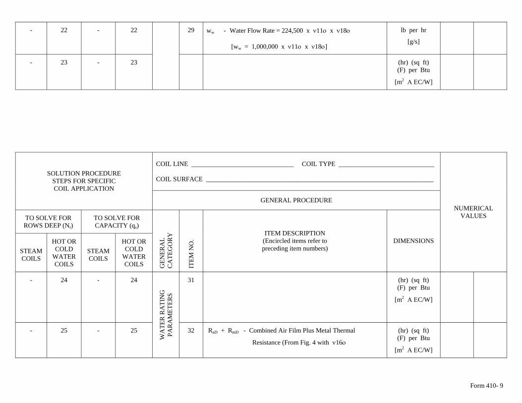
- 22 - 22 29 ww - Water Flow Rate = 224,500 x ν11ο x ν18ο
[ww = 1,000,000 x ν11ο x ν18ο]
lb per hr
[g/s]
- 23 - 23 (hr) (sq ft) (F) per Btu
[m2 Α ΕC/W]
COIL LINE _______________________________ COIL TYPE _____________________________ COIL SURFACE _____________________________________________________________________
SOLUTION PROCEDURE STEPS FOR SPECIFIC COIL APPLICATION
GENERAL PROCEDURE
TO SOLVE FOR ROWS DEEP (Nr)
TO SOLVE FOR CAPACITY (qs)
STEAM COILS
HOT OR COLD
WATER COILS
STEAM COILS
HOT OR COLD
WATER COILS
GEN
ERA
L C
ATE
GO
RY
ITE
M N
O.
ITEM DESCRIPTION (Encircled items refer to preceding item numbers)
DIMENSIONS
NUMERICAL VALUES
- 24 - 24 31 (hr) (sq ft) (F) per Btu
[m2 Α ΕC/W]
- 25 - 25
WA
TER
RA
TIN
G
PAR
AM
ETER
S
32 RaD + RmD - Combined Air Film Plus Metal Thermal
Resistance (From Fig. 4 with ν16ο
(hr) (sq ft) (F) per Btu
[m2 Α ΕC/W]
Form 410- 9
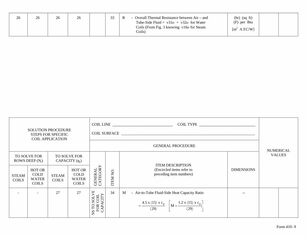
26 26 26 26 33 R - Overall Thermal Resistance between Air – and (hr) (sq ft) (F) per Btu Tube-Side Fluid = ν31ο + ν32ο for Water
Coils (From Fig. 3 knowing ν16ο for Steam [m2 Α ΕC/W] Coils)
COIL LINE _______________________________ COIL TYPE _____________________________ COIL SURFACE _____________________________________________________________________
SOLUTION PROCEDURE STEPS FOR SPECIFIC COIL APPLICATION
GENERAL PROCEDURE
TO SOLVE FOR ROWS DEEP (Nr)
TO SOLVE FOR CAPACITY (qs)
STEAM COILS
HOT OR COLD
WATER COILS
STEAM COILS
HOT OR COLD
WATER COILS
GEN
ERA
L C
ATE
GO
RY
ITE
M N
O.
ITEM DESCRIPTION (Encircled items refer to preceding item numbers)
DIMENSIONS
NUMERICAL VALUES
- - 27 27
CC
UO
NS
TO S
OLV
E FO
R C
OIL
C
APA
CIT
Y 34 M - Air-to-Tube Fluid-Side Heat Capacity Ratio
⎥⎦
⎤⎢⎣
⎡
⟩⟨
⟩⟨=
⟩⟨
⟩⟨=
29cx15x2.1
M29
cx15x5.4 pp
--
Form 410- 9
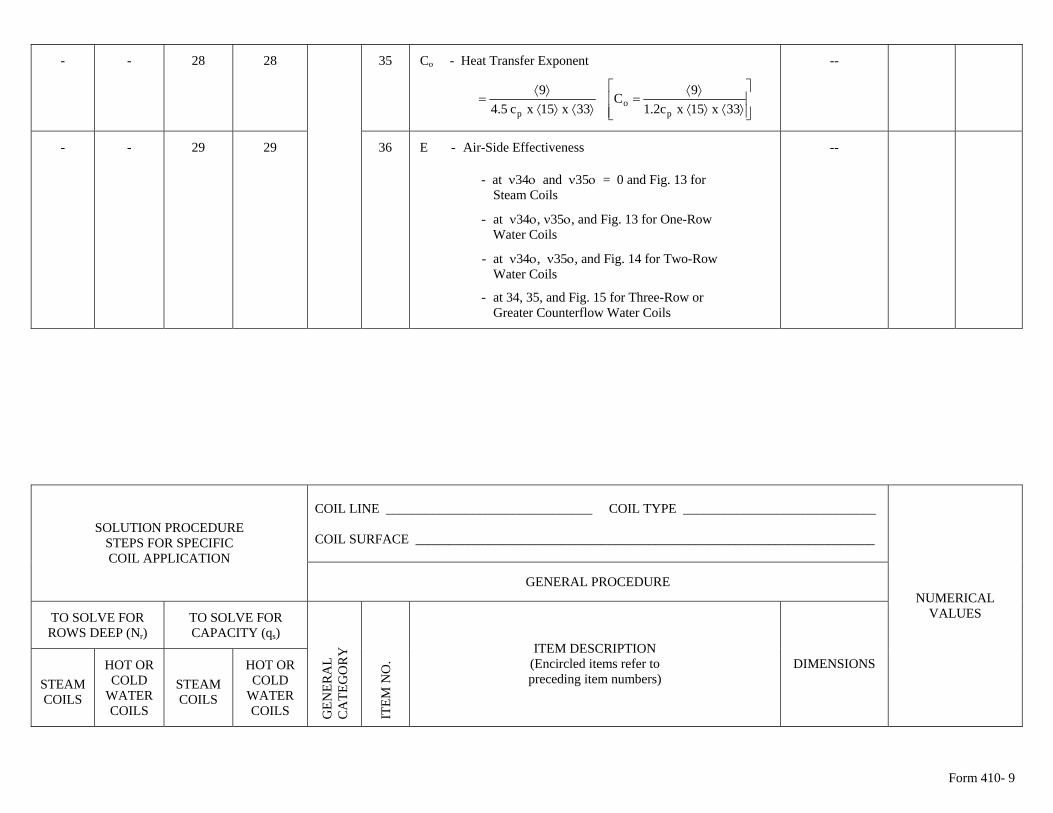
- - 28 28 35 Co - Heat Transfer Exponent
⎥⎥⎦
⎤
⎢⎢⎣
⎡
⟩⟨⟩⟨⟩⟨
=⟩⟨⟩⟨
⟩⟨=
33x15xc2.19C
33x15xc5.49
po
p
--
- - 29 29 36 E - Air-Side Effectiveness
- at ν34ο and ν35ο = 0 and Fig. 13 for Steam Coils
- at ν34ο, ν35ο, and Fig. 13 for One-Row Water Coils
- at ν34ο, ν35ο, and Fig. 14 for Two-Row Water Coils
- at 34, 35, and Fig. 15 for Three-Row or Greater Counterflow Water Coils
--
COIL LINE _______________________________ COIL TYPE _____________________________ COIL SURFACE _____________________________________________________________________
SOLUTION PROCEDURE STEPS FOR SPECIFIC COIL APPLICATION
GENERAL PROCEDURE
TO SOLVE FOR ROWS DEEP (Nr)
TO SOLVE FOR CAPACITY (qs)
STEAM COILS
HOT OR COLD
WATER COILS
STEAM COILS
HOT OR COLD
WATER COILS
GEN
ERA
L C
ATE
GO
RY
ITE
M N
O.
ITEM DESCRIPTION (Encircled items refer to preceding item numbers)
DIMENSIONS
NUMERICAL VALUES
Form 410- 9
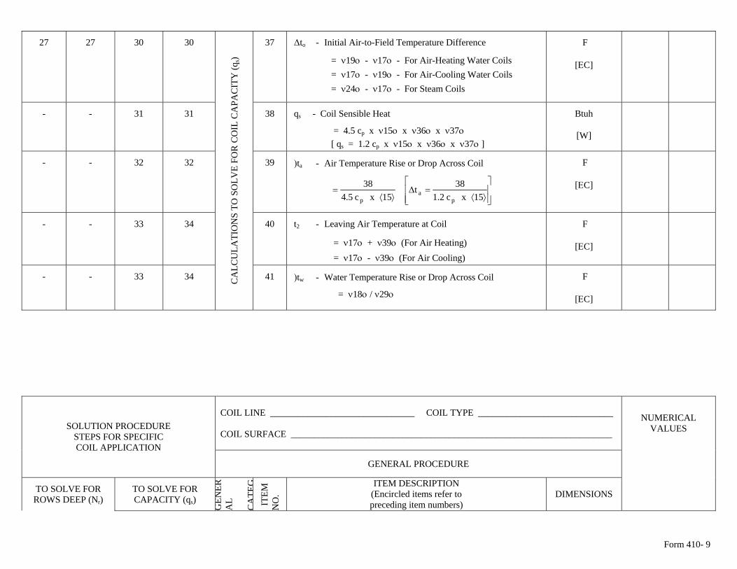
27 27 30 30 37 Δto - Initial Air-to-Field Temperature Difference
= ν19ο - ν17ο - For Air-Heating Water Coils = ν17ο - ν19ο - For Air-Cooling Water Coils = ν24ο - ν17ο - For Steam Coils
F
[ΕC]
- - 31 31 38 qs - Coil Sensible Heat
= 4.5 cp x ν15ο x ν36ο x ν37ο [ qs = 1.2 cp x ν15ο x ν36ο x ν37ο ]
Btuh
[W]
- - 32 32 39 )ta - Air Temperature Rise or Drop Across Coil
⎥⎥⎦
⎤
⎢⎢⎣
⎡
⟩⟨=Δ
⟩⟨=
15xc2.138t
15xc5.438
pa
p
F
[ΕC]
- - 33 34 40 t2 - Leaving Air Temperature at Coil
= ν17ο + ν39ο (For Air Heating) = ν17ο - ν39ο (For Air Cooling)
F
[ΕC]
- - 33 34 CA
LCU
LATI
ON
S TO
SO
LVE
FOR
CO
IL C
APA
CIT
Y (q
s)
41 )tw - Water Temperature Rise or Drop Across Coil
= ν18ο / ν29ο
F
[ΕC]
COIL LINE _______________________________ COIL TYPE _____________________________ COIL SURFACE _____________________________________________________________________
SOLUTION PROCEDURE STEPS FOR SPECIFIC COIL APPLICATION
GENERAL PROCEDURE
TO SOLVE FOR ROWS DEEP (Nr)
TO SOLVE FOR CAPACITY (qs)
GEN
ERA
L C
ATE
G I
TEM
N
O.
ITEM DESCRIPTION (Encircled items refer to preceding item numbers)
DIMENSIONS
NUMERICAL VALUES
Form 410- 9
STEAM COILS
HOT OR COLD
WATER COILS
STEAM COILS
HOT OR COLD
WATER COILS
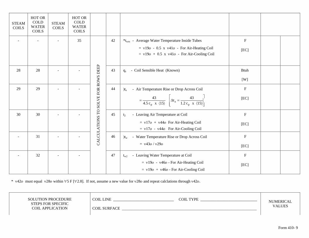
- - - 35 42 *twm - Average Water Temperature Inside Tubes
= ν19ο - 0.5 x ν41ο - For Air-Heating Coil = ν19ο + 0.5 x ν41ο - For Air-Cooling Coil
F
[ΕC]
28 28 - - 43 qs - Coil Sensible Heat (Known) Btuh
[W]
29 29 - - 44 )ta - Air Temperature Rise or Drop Across Coil
⎥⎥⎦
⎤
⎢⎢⎣
⎡
⟩⟨=Δ
⟩⟨=
15xc2.143t
15xc5.443
pa
p
F
[ΕC]
30 30 - - 45 t2 - Leaving Air Temperature at Coil
= ν17ο + ν44ο For Air-Heating Coil = ν17ο - ν44ο For Air-Cooling Coil
F
[ΕC]
- 31 - - 46 )tw - Water Temperature Rise or Drop Across Coil
= ν43ο / ν29ο
F
[ΕC]
CA
LCU
LATI
ON
S TO
SO
LVE
FOR
RO
WS
DEE
P
- 32 - - 47 tw2 - Leaving Water Temperature at Coil
= ν19ο - ν46ο - For Air-Heating Coil
= ν19ο + ν46ο - For Air-Cooling Coil
F
[ΕC]
* ν42ο must equal ν28ο within ∀5 F [∀2.8]. If not, assume a new value for ν28ο and repeat calclations through ν42ο.
SOLUTION PROCEDURE STEPS FOR SPECIFIC COIL APPLICATION
COIL LINE _______________________________ COIL TYPE _____________________________ COIL SURFACE _____________________________________________________________________
NUMERICAL VALUES
Form 410- 9
GENERAL PROCEDURE
TO SOLVE FOR ROWS DEEP (Nr)
TO SOLVE FOR CAPACITY (qs)
STEAM COILS
HOT OR COLD
WATER COILS
STEAM COILS
HOT OR COLD
WATER COILS
GEN
ERA
L C
ATE
GO
RY
ITE
M N
O.
ITEM DESCRIPTION (Encircled items refer to preceding item numbers)
DIMENSIONS
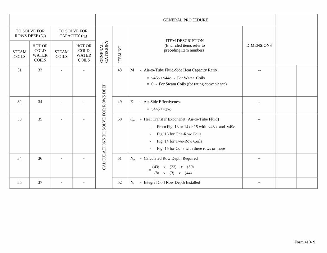
31 33 - - 48 M - Air-to-Tube Fluid-Side Heat Capacity Ratio
= ν46ο / ν44ο - For Water Coils = 0 - For Steam Coils (for rating convenience)
--
32 34 - - 49 E - Air-Side Effectiveness
= ν44ο / ν37ο
--
33 35 - - 50 Co - Heat Transfer Exponenet (Air-to-Tube Fluid)
- From Fig. 13 or 14 or 15 with ν48ο and ν49ο
- Fig. 13 for One-Row Coils
- Fig. 14 for Two-Row Coils
- Fig. 15 for Coils with three rows or more
--
34 36 - - 51 Nrc - Calculated Row Depth Required
⟩⟨⟩⟨⟩⟨⟩⟨⟩⟨⟩⟨
=44x3x8
50x33x43
--
CA
LCU
LATI
ON
S TO
SO
LVE
FOR
RO
WS
DEE
P
35 37 - - 52 Nt - Integral Coil Row Depth Installed --
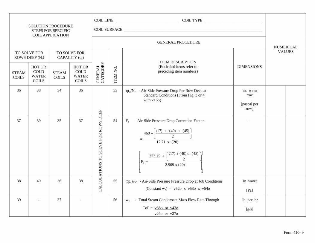
Form 410- 9
COIL LINE _______________________________ COIL TYPE _____________________________ COIL SURFACE _____________________________________________________________________
SOLUTION PROCEDURE STEPS FOR SPECIFIC COIL APPLICATION
GENERAL PROCEDURE
TO SOLVE FOR ROWS DEEP (Nr)
TO SOLVE FOR CAPACITY (qs)
STEAM COILS
HOT OR COLD
WATER COILS
STEAM COILS
HOT OR COLD
WATER COILS
GEN
ERA
L C
ATE
GO
RY
ITE
M N
O.
ITEM DESCRIPTION (Encircled items refer to preceding item numbers)
DIMENSIONS
NUMERICAL VALUES
36 38 34 36 53 )pst/Nr - Air-Side Pressure Drop Per Row Deep at Standard Conditions (From Fig. 3 or 4 with ν16ο)
in. waterrow
[pascal per
row]
37 39 35 37 54 Fa - Air-Side Pressure Drop Correction Factor
⟩⟨
⎥⎦⎤
⎢⎣⎡ ⟩⟨+⟩⟨+⟩⟨
+=
20x71.172
454017460
⎥⎥⎥⎥
⎦
⎤
⎢⎢⎢⎢
⎣
⎡
⟩⟨
⎟⎠⎞
⎜⎝⎛ ⟩⟨⟩⟨+⟩⟨
+=
20x909.22
45or401715.273Fa
--
38 40 36 38 55 ()pa)JOB - Air-Side Pressure Pressure Drop at Job Conditions
(Constant wa) = ν52ο x ν53ο x ν54ο
in water
[Pa]
39 - 37 -
CA
LCU
LATI
ON
S TO
SO
LVE
FOR
RO
WS
DEE
P
56 wv - Total Steam Condensate Mass Flow Rate Through
Coil = ν38ο or ν43ο ν26ο or ν27ο
lb per hr
[g/s]
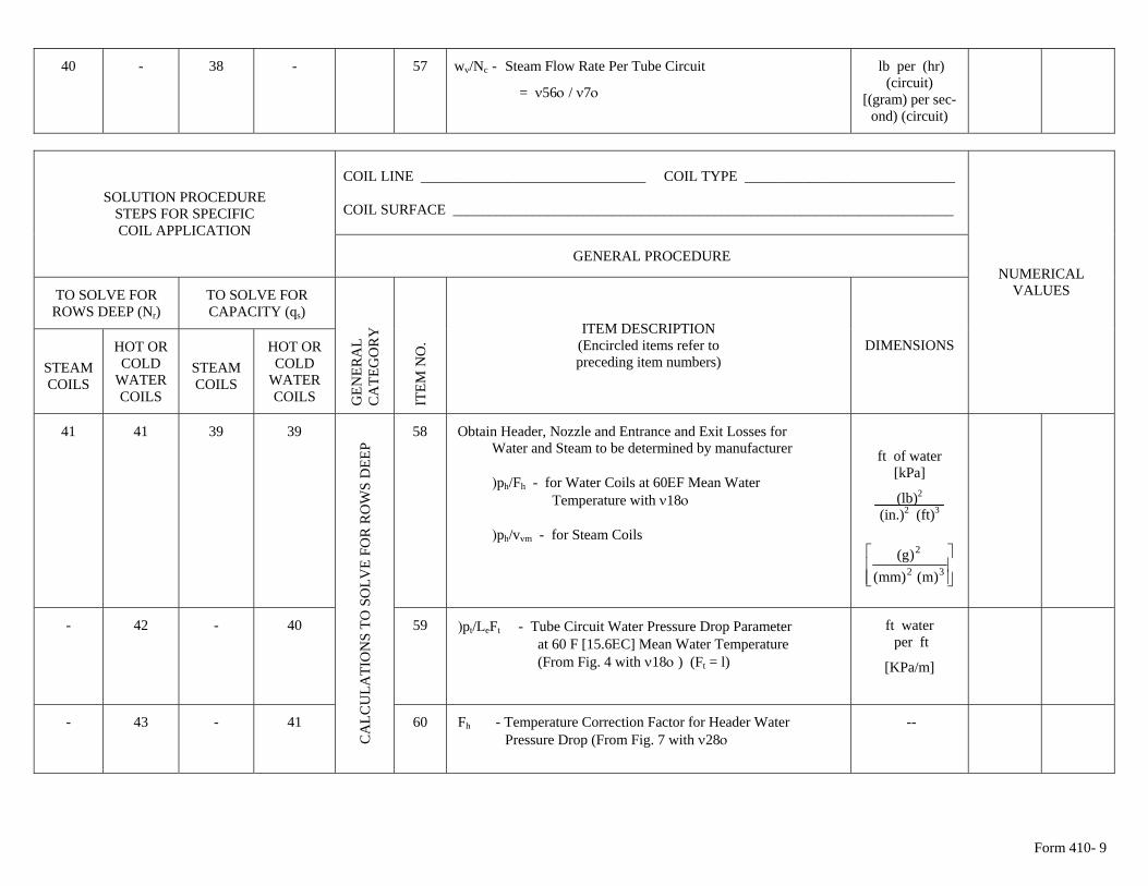
Form 410- 9
40 - 38 - 57 wv/Nc - Steam Flow Rate Per Tube Circuit lb per (hr) (circuit)
[(gram) per sec- = ν56ο / ν7ο ond) (circuit)
COIL LINE _______________________________ COIL TYPE _____________________________ COIL SURFACE _____________________________________________________________________
SOLUTION PROCEDURE STEPS FOR SPECIFIC COIL APPLICATION
GENERAL PROCEDURE
TO SOLVE FOR ROWS DEEP (Nr)
TO SOLVE FOR CAPACITY (qs)
STEAM COILS
HOT OR COLD
WATER COILS
STEAM COILS
HOT OR COLD
WATER COILS
GEN
ERA
L C
ATE
GO
RY
ITE
M N
O.
ITEM DESCRIPTION (Encircled items refer to preceding item numbers)
DIMENSIONS
NUMERICAL VALUES
41 41 39 39 Obtain Header, Nozzle and Entrance and Exit Losses for Water and Steam to be determined by manufacturer )ph/Fh - for Water Coils at 60ΕF Mean Water Temperature with ν18ο )ph/vvm - for Steam Coils
ft of water [kPa]
(lb)2
(in.)2 (ft)3
⎥⎥⎦
⎤
⎢⎢⎣
⎡32
2
)m()mm()g(
58
- 42 - 40 59 )pt/LeFt - Tube Circuit Water Pressure Drop Parameter at 60 F [15.6ΕC] Mean Water Temperature (From Fig. 4 with ν18ο ) (Ft = l)
ft water per ft
[KPa/m]
- 43 - 41
CA
LCU
LATI
ON
S TO
SO
LVE
FOR
RO
WS
DEE
P
60 Fh - Temperature Correction Factor for Header Water Pressure Drop (From Fig. 7 with ν28ο
--
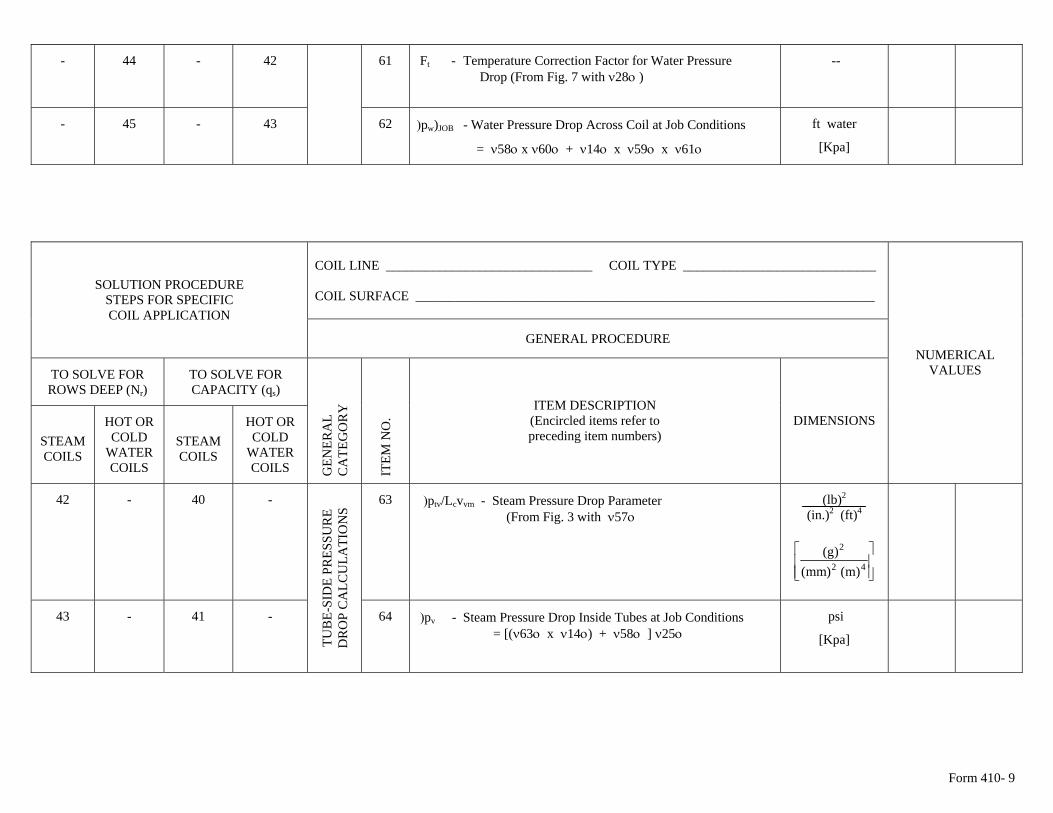
Form 410- 9
- 44 - 42 61 Ft - Temperature Correction Factor for Water Pressure -- Drop (From Fig. 7 with ν28ο )
- 45 - 43 62 )pw)JOB - Water Pressure Drop Across Coil at Job Conditions
= ν58ο x ν60ο + ν14ο x ν59ο x ν61ο
ft water
[Kpa]
COIL LINE _______________________________ COIL TYPE _____________________________ COIL SURFACE _____________________________________________________________________
SOLUTION PROCEDURE STEPS FOR SPECIFIC COIL APPLICATION
GENERAL PROCEDURE
TO SOLVE FOR ROWS DEEP (Nr)
TO SOLVE FOR CAPACITY (qs)
STEAM COILS
HOT OR COLD
WATER COILS
STEAM COILS
HOT OR COLD
WATER COILS
GEN
ERA
L C
ATE
GO
RY
ITE
M N
O.
ITEM DESCRIPTION (Encircled items refer to preceding item numbers)
DIMENSIONS
NUMERICAL VALUES
42 - 40 - 63 )ptv/Lcvvm - Steam Pressure Drop Parameter (From Fig. 3 with ν57ο
(lb)2
(in.)2 (ft)4
⎥⎥⎦
⎤
⎢⎢⎣
⎡42
2
)m()mm()g(
43 - 41 -
TUB
E-SI
DE
PRES
SUR
E D
RO
P C
ALC
ULA
TIO
NS
64 psi )pv - Steam Pressure Drop Inside Tubes at Job Conditions = [(ν63ο x ν14ο) + ν58ο ] ν25ο [Kpa]
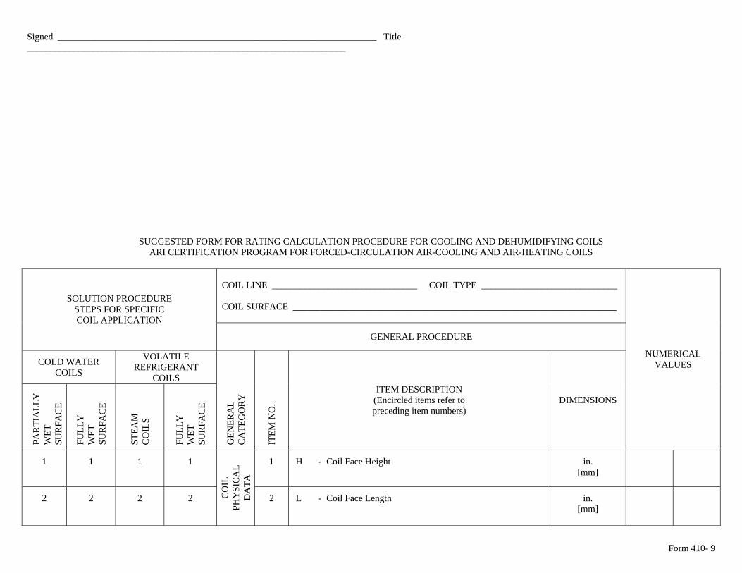
Form 410- 9
Signed ____________________________________________________________________ Title ____________________________________________________________________
SUGGESTED FORM FOR RATING CALCULATION PROCEDURE FOR COOLING AND DEHUMIDIFYING COILS ARI CERTIFICATION PROGRAM FOR FORCED-CIRCULATION AIR-COOLING AND AIR-HEATING COILS
COIL LINE _______________________________ COIL TYPE _____________________________ COIL SURFACE _____________________________________________________________________
SOLUTION PROCEDURE STEPS FOR SPECIFIC COIL APPLICATION
GENERAL PROCEDURE
COLD WATER COILS
VOLATILE REFRIGERANT
COILS
PA
RTI
ALL
Y
WET
S
UR
FAC
E
FU
LLY
W
ET
SU
RFA
CE
STE
AM
C
OIL
S
FU
LLY
W
ET
SU
RFA
CE
GEN
ERA
L C
ATE
GO
RY
ITE
M N
O.
ITEM DESCRIPTION (Encircled items refer to preceding item numbers)
DIMENSIONS
NUMERICAL VALUES
1 1 1 1 1 H - Coil Face Height in. [mm]
2 2 2 2 CO
IL
PHY
SIC
AL
DA
TA
2 L - Coil Face Length
in. [mm]
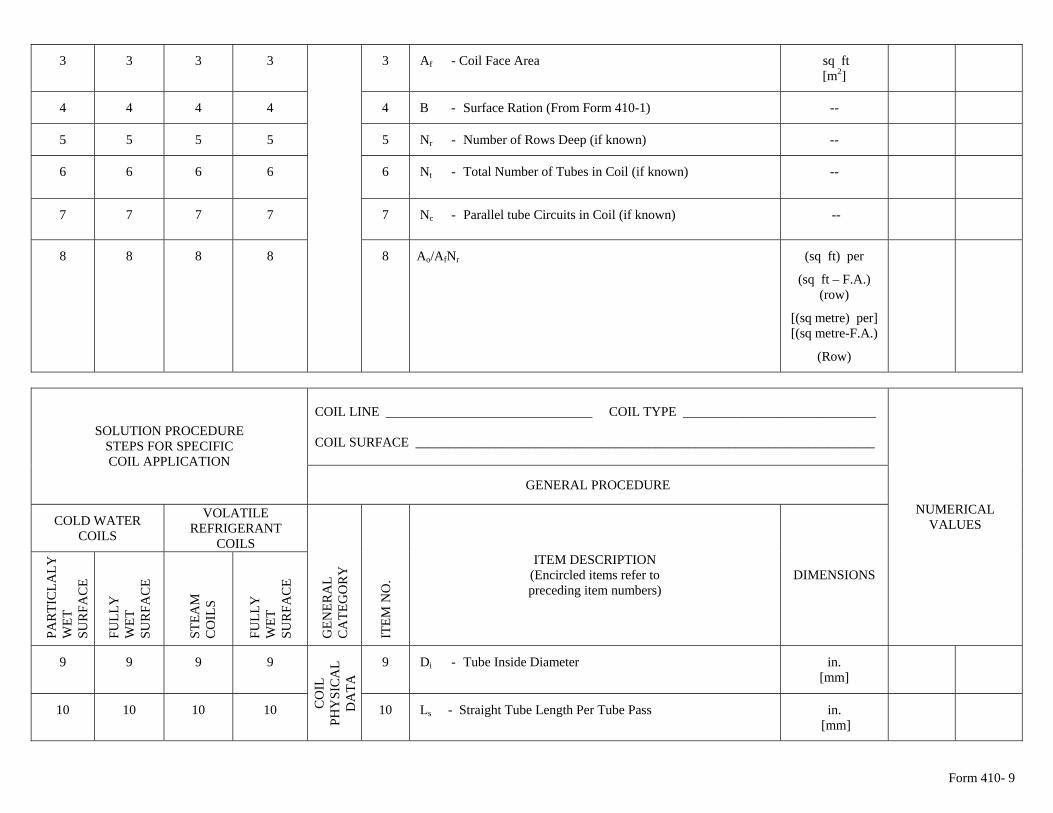
Form 410- 9
3 3 3 3 3 Af - Coil Face Area sq ft [m2]
4 4 4 4 4 B - Surface Ration (From Form 410-1) --
5 5 5 5 5 Nr - Number of Rows Deep (if known) --
6 6 6 6 6 Nt - Total Number of Tubes in Coil (if known) --
7 7 7 7 7 Nc - Parallel tube Circuits in Coil (if known) --
8 8 8 8 8 Ao/AfNr (sq ft) per
(sq ft – F.A.) (row)
[(sq metre) per] [(sq metre-F.A.)
(Row)
COIL LINE _______________________________ COIL TYPE _____________________________ COIL SURFACE _____________________________________________________________________
SOLUTION PROCEDURE STEPS FOR SPECIFIC COIL APPLICATION
GENERAL PROCEDURE
COLD WATER COILS
VOLATILE REFRIGERANT
COILS
PA
RTI
CLA
LY
WET
S
UR
FAC
E
FU
LLY
W
ET
SU
RFA
CE
STE
AM
C
OIL
S
FU
LLY
W
ET
SU
RFA
CE
GEN
ERA
L C
ATE
GO
RY
ITE
M N
O.
ITEM DESCRIPTION (Encircled items refer to preceding item numbers)
DIMENSIONS
NUMERICAL VALUES
9 9 9 9 9 Di - Tube Inside Diameter in. [mm]
10 10 10 10 CO
IL
PHY
SIC
AL
DA
TA
10 Ls - Straight Tube Length Per Tube Pass in. [mm]
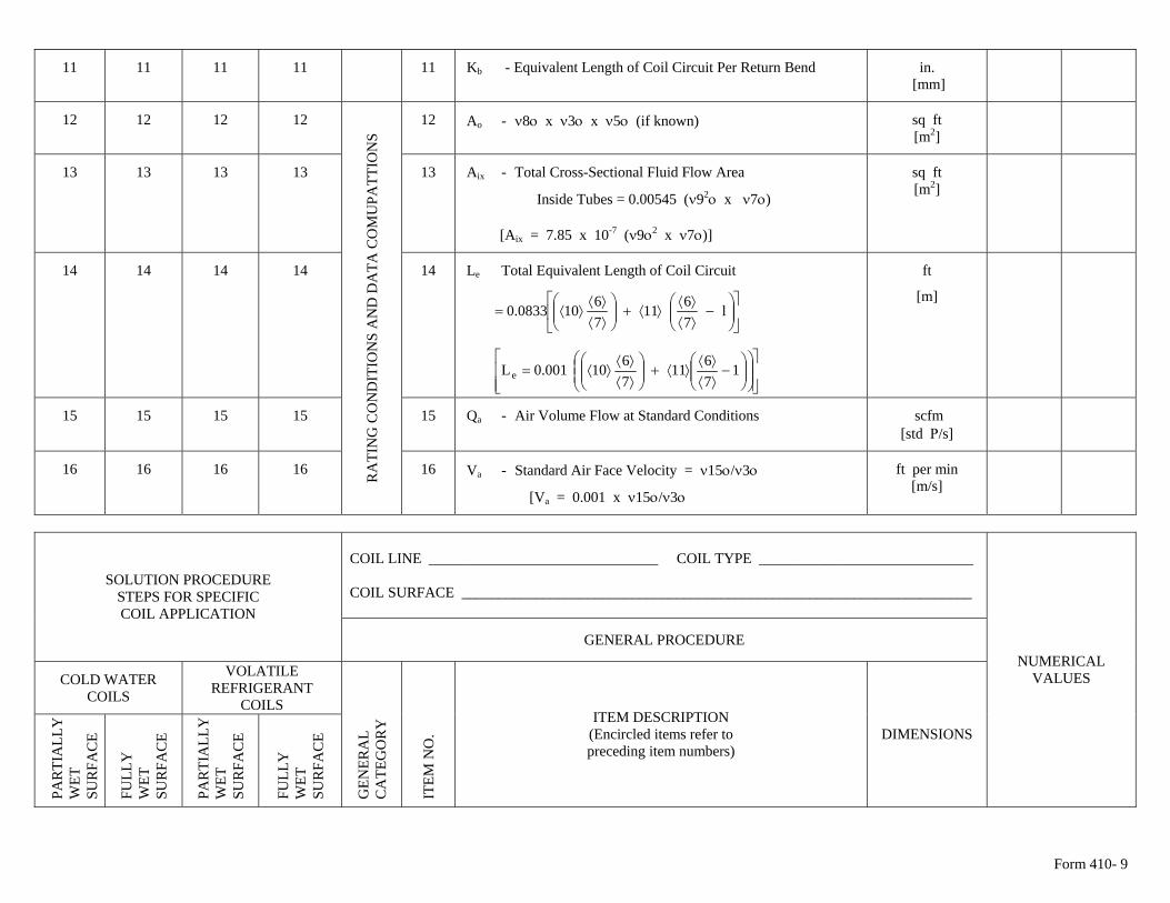
Form 410- 9
11 11 11 11 11 Kb - Equivalent Length of Coil Circuit Per Return Bend in. [mm]
12 12 12 12 12 Ao - ν8ο x ν3ο x ν5ο (if known) sq ft [m2]
13 13 13 13 13 Aix - Total Cross-Sectional Fluid Flow Area
Inside Tubes = 0.00545 (ν92ο x ν7ο)
[Aix = 7.85 x 10⁻⁷ (ν9ο2 x ν7ο)]
sq ft [m2]
14 14 14 14 14 Le Total Equivalent Length of Coil Circuit
⎥⎦
⎤⎢⎣
⎡⎟⎟⎠
⎞⎜⎜⎝
⎛−
⟩⟨⟩⟨
⟩⟨+⎟⎟⎠
⎞⎜⎜⎝
⎛⟩⟨⟩⟨
⟩⟨= l7611
76100833.0
⎥⎥⎦
⎤
⎢⎢⎣
⎡⎟⎟⎠
⎞⎜⎜⎝
⎛⎟⎟⎠
⎞⎜⎜⎝
⎛−
⟩⟨⟩⟨
⟩⟨+⎟⎟⎠
⎞⎜⎜⎝
⎛⟩⟨⟩⟨
⟩⟨= 17611
7610001.0Le
ft
[m]
15 15 15 15 15 Qa - Air Volume Flow at Standard Conditions scfm [std Ρ/s]
16 16 16 16 RA
TIN
G C
ON
DIT
ION
S A
ND
DA
TA C
OM
UPA
TTIO
NS
16 Va - Standard Air Face Velocity = ν15ο/ν3ο
[Va = 0.001 x ν15ο/ν3ο
ft per min [m/s]
COIL LINE _______________________________ COIL TYPE _____________________________ COIL SURFACE _____________________________________________________________________
SOLUTION PROCEDURE STEPS FOR SPECIFIC COIL APPLICATION
GENERAL PROCEDURE
COLD WATER COILS
VOLATILE REFRIGERANT
COILS
PA
RTI
ALL
Y
WET
S
UR
FAC
E
FU
LLY
W
ET
SU
RFA
CE
PA
RTI
ALL
Y
WET
S
UR
FAC
E
FU
LLY
W
ET
SU
RFA
CE
GEN
ERA
L C
ATE
GO
RY
ITE
M N
O.
ITEM DESCRIPTION (Encircled items refer to preceding item numbers)
DIMENSIONS
NUMERICAL VALUES
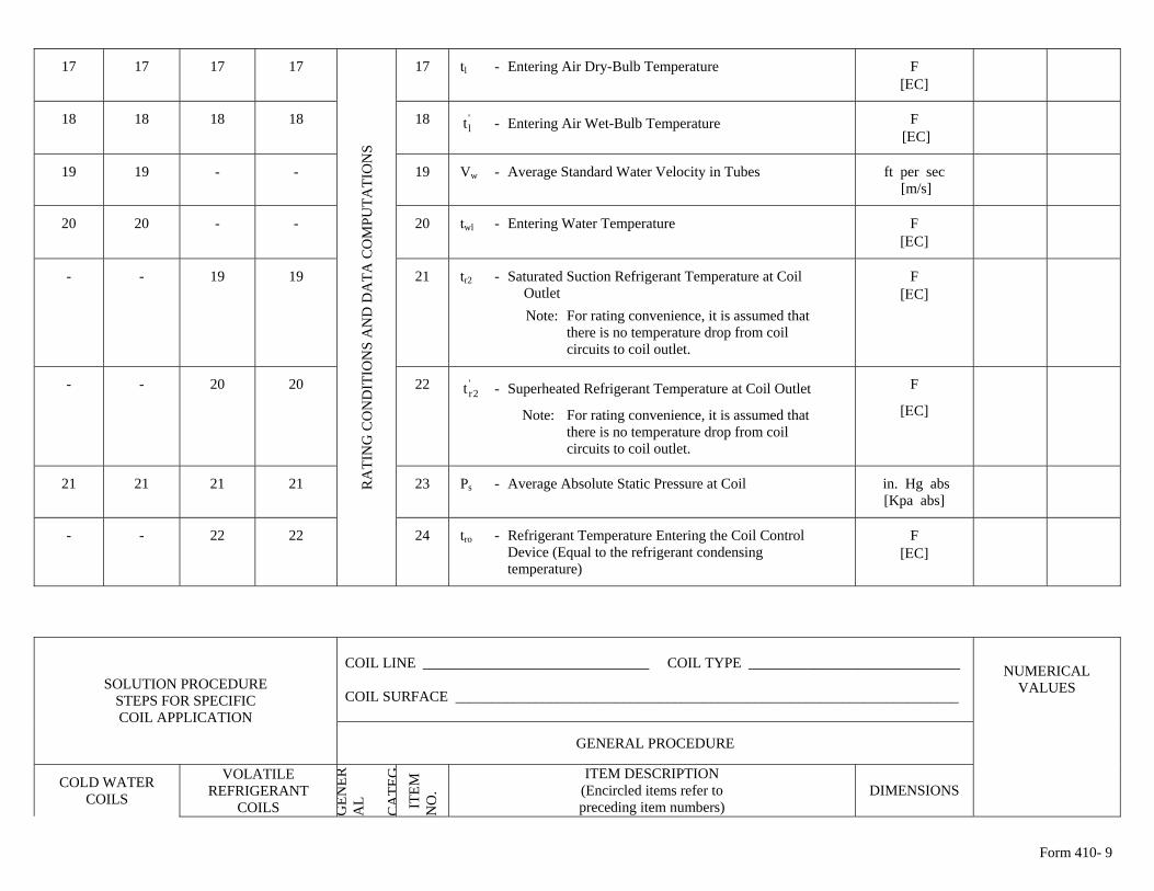
Form 410- 9
17 17 17 17 17 tl - Entering Air Dry-Bulb Temperature F [ΕC]
18 18 18 18 18 - Entering Air Wet-Bulb Temperature 'lt F
[ΕC]
19 19 - - 19 Vw - Average Standard Water Velocity in Tubes ft per sec [m/s]
20 20 - - 20 twl - Entering Water Temperature F
[ΕC]
- - 19 19 21 tr2 - Saturated Suction Refrigerant Temperature at Coil Outlet Note: For rating convenience, it is assumed that there is no temperature drop from coil circuits to coil outlet.
F [ΕC]
- - 20 20 22 - Superheated Refrigerant Temperature at Coil Outlet '2rt
Note: For rating convenience, it is assumed that there is no temperature drop from coil circuits to coil outlet.
F
[ΕC]
21 21 21 21 23 Ps - Average Absolute Static Pressure at Coil in. Hg abs [Kpa abs]
- - 22 22
RA
TIN
G C
ON
DIT
ION
S A
ND
DA
TA C
OM
PUTA
TIO
NS
24 tro - Refrigerant Temperature Entering the Coil Control Device (Equal to the refrigerant condensing
F [ΕC]
temperature)
COIL LINE _______________________________ COIL TYPE _____________________________ COIL SURFACE _____________________________________________________________________
SOLUTION PROCEDURE STEPS FOR SPECIFIC COIL APPLICATION
GENERAL PROCEDURE
COLD WATER COILS
VOLATILE REFRIGERANT
COILS GEN
ERA
L C
ATE
G I
TEM
N
O.
ITEM DESCRIPTION (Encircled items refer to preceding item numbers)
DIMENSIONS
NUMERICAL VALUES
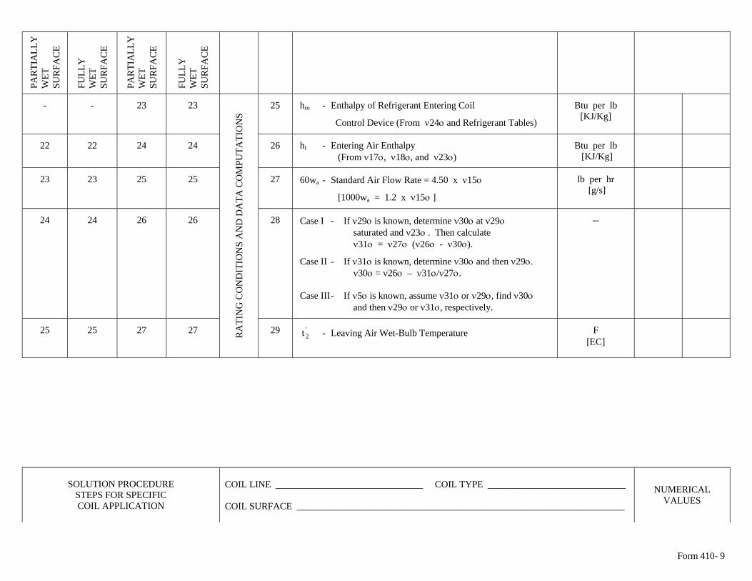
Form 410- 9
PA
RTI
ALL
Y
WET
S
UR
FAC
E
FU
LLY
W
ET
SU
RFA
CE
PA
RTI
ALL
Y
WET
S
UR
FAC
E
FU
LLY
W
ET
SU
RFA
CE
- - 23 23 25 hro - Enthalpy of Refrigerant Entering Coil
Control Device (From ν24ο and Refrigerant Tables)
Btu per lb [KJ/Kg]
22 22 24 24 26 hl - Entering Air Enthalpy (From ν17ο, ν18ο, and ν23ο)
Btu per lb [KJ/Kg]
23 23 25 25 27 60wa - Standard Air Flow Rate = 4.50 x ν15ο
[1000wa = 1.2 x ν15ο ]
lb per hr [g/s]
24 24 26 26 28 Case I - If ν29ο is known, determine ν30ο at ν29ο saturated and ν23ο . Then calculate ν31ο = ν27ο (ν26ο - ν30ο).
Case II - If ν31ο is known, determine ν30ο and then ν29ο. ν30ο = ν26ο – ν31ο/ν27ο. Case III - If ν5ο is known, assume ν31ο or ν29ο, find ν30ο and then ν29ο or ν31ο, respectively.
--
25 25 27 27 RA
TIN
G C
ON
DIT
ION
S A
ND
DA
TA C
OM
PUTA
TIO
NS
29 - Leaving Air Wet-Bulb Temperature '2t
F [ΕC]
SOLUTION PROCEDURE STEPS FOR SPECIFIC COIL APPLICATION
COIL LINE _______________________________ COIL TYPE _____________________________ COIL SURFACE _____________________________________________________________________
NUMERICAL VALUES
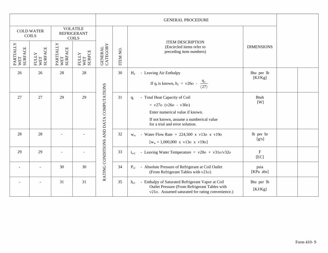
Form 410- 9
GENERAL PROCEDURE
COLD WATER COILS
VOLATILE REFRIGERANT
COILS
PA
RTI
ALL
Y
WET
S
UR
FAC
E
FU
LLY
W
ET
SU
RFA
CE
PA
RTI
ALL
Y
WET
S
UR
FAC
E
FU
LLY
W
ET
SU
RFC
E
GEN
ERA
L C
ATE
GO
RY
ITE
M N
O.
ITEM DESCRIPTION (Encircled items refer to preceding item numbers)
DIMENSIONS
26 26 28 28 30 H2 - Leaving Air Enthalpy
If qt is known, h2 = ν26ο - ⟩⟨27
q t
Btu per lb [KJ/Kg]
27 27 29 29 31 qt - Total Heat Capacity of Coil
= ν27ο (ν26ο - ν30ο)
Enter numerical value if known.
If not known, assume a numberical value for a trial and error solution.
Btuh [W]
28 28 - - 32 ww - Water Flow Rate = 224,500 x ν13ο x ν19ο
[ww = 1,000,000 x ν13ο x ν19ο]
lb per hr [g/s]
29 29 - - 33 tw2 - Leaving Water Temperature = ν20ο + ν31ο/ν32ο F [ΕC]
- - 30 30 34 Pr2 - Absolute Pressure of Refrigerant at Coil Outlet (From Refrigerant Tables with ν21ο)
psia [KPa abs]
- - 31 31 RA
TIN
G C
ON
DIT
ION
S A
ND
DA
TA C
OM
PUTA
TIO
NS
35 hr2 - Enthalpy of Saturated Refrigerant Vapor at Coil Outlet Pressure (From Refrigerant Tables with ν21ο. Assumed saturated for rating convenience.)
Btu per lb
[KJ/Kg]
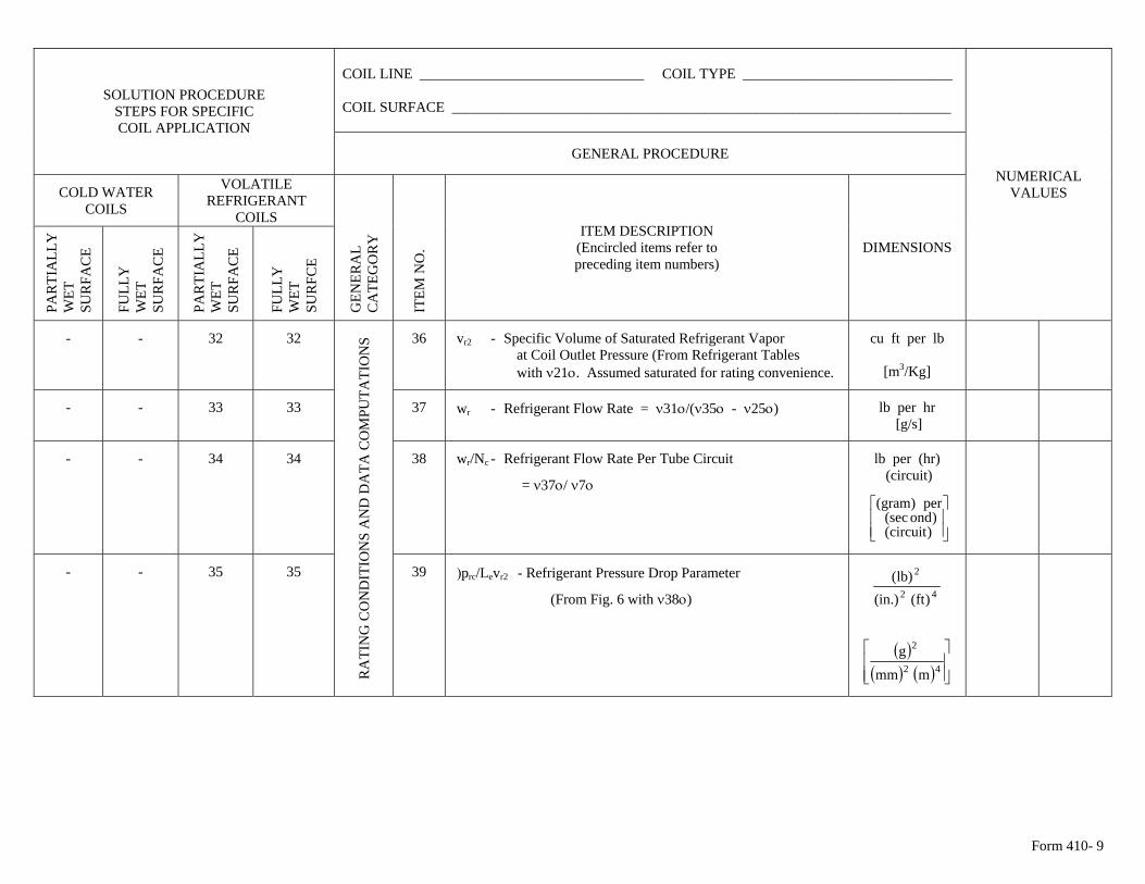
Form 410- 9
COIL LINE _______________________________ COIL TYPE _____________________________ COIL SURFACE _____________________________________________________________________
SOLUTION PROCEDURE STEPS FOR SPECIFIC COIL APPLICATION
GENERAL PROCEDURE
COLD WATER COILS
VOLATILE REFRIGERANT
COILS
PA
RTI
ALL
Y
WET
S
UR
FAC
E
FU
LLY
W
ET
SU
RFA
CE
PA
RTI
ALL
Y
WET
S
UR
FAC
E
FU
LLY
W
ET
SU
RFC
E
GEN
ERA
L C
ATE
GO
RY
ITE
M N
O.
ITEM DESCRIPTION (Encircled items refer to preceding item numbers)
DIMENSIONS
NUMERICAL VALUES
- - 32 32 36 vr2 - Specific Volume of Saturated Refrigerant Vapor at Coil Outlet Pressure (From Refrigerant Tables with ν21ο. Assumed saturated for rating convenience.
cu ft per lb
[m3/Kg]
- - 33 33 37 wr - Refrigerant Flow Rate = ν31ο/(ν35ο - ν25ο) lb per hr [g/s]
- - 34 34 38 wr/Nc - Refrigerant Flow Rate Per Tube Circuit
= ν37ο/ ν7ο
lb per (hr) (circuit)
⎥⎥⎦
⎤
⎢⎢⎣
⎡
)circuit()ond(sec
per)gram(
- - 35 35
RA
TIN
G C
ON
DIT
ION
S A
ND
DA
TA C
OM
PUTA
TIO
NS
39 )prc/Levr2 - Refrigerant Pressure Drop Parameter
(From Fig. 6 with ν38ο)
42
2
)ft(.)in()lb(
( )( ) ( ) ⎥
⎥⎦
⎤
⎢⎢⎣
⎡42
2
mmmg
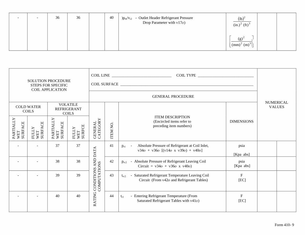
Form 410- 9
- - 36 36 40 )prh/vr2 - Outlet Header Refrigerant Pressure Drop Parameter with ν17ο) ( )
32
2
)ft(.)in(lb
⎥⎥⎦
⎤
⎢⎢⎣
⎡32
2
)m()mm()g(
COIL LINE _______________________________ COIL TYPE _____________________________ COIL SURFACE _____________________________________________________________________
SOLUTION PROCEDURE STEPS FOR SPECIFIC COIL APPLICATION
GENERAL PROCEDURE
COLD WATER COILS
VOLATILE REFRIGERANT
COILS
PA
RTI
ALL
Y
WET
S
UR
FAC
E
FU
LLY
W
ET
SU
RFA
CE
PA
RTI
ALL
Y
WET
S
UR
FAC
E
FU
LLY
W
ET
SU
RFC
E
GEN
ERA
L C
ATE
GO
RY
ITE
M N
O.
ITEM DESCRIPTION (Encircled items refer to preceding item numbers)
DIMENSIONS
NUMERICAL VALUES
- - 37 37 41 pr1 - Absolute Pressure of Refrigerant at Coil Inlet, ν34ο + ν36ο [(ν14ο x ν39ο) + ν40ο]
psia
[Kpa abs]
- - 38 38 42 prc2 - Absolute Pressure of Refrigerant Leaving Coil Circuit = ν34ο + ν36ο x ν40ο)
psia [Kpa abs]
- - 39 39 43 trc2 - Saturated Refrigerant Temperature Leaving Coil
Circuit (From ν42ο and Refrigerant Tables) F
[ΕC]
- - 40 40
RA
TIN
G C
ON
DIT
ION
S A
ND
DA
TA
CO
MPU
TATI
ON
S
44 tr1 - Entering Refrigerant Temperature (From Saturated Refrigerant Tables with ν41ο)
F [ΕC]
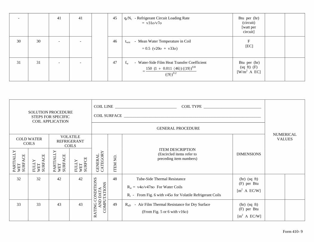
Form 410- 9
- 41 41 45 qt/Nc - Refrigerant Circuit Loading Rate = ν31ο/ν7ο
Btu per (hr) (circuit) [watt per circuit]
30 30 - - 46 twm - Mean Water Temperature in Coil
= 0.5 (ν20ο + ν33ο)
F [ΕC]
31 31 - - 47 fw - Water-Side Film Heat Transfer Coefficient
2.0
8.0
)9()19()46011.01(150
⟩⟨⟩⟨⟩⟨+
=
Btu per (hr) (sq ft) (F)
[W/m2 Α ΕC]
COIL LINE _______________________________ COIL TYPE _____________________________ COIL SURFACE _____________________________________________________________________
SOLUTION PROCEDURE STEPS FOR SPECIFIC COIL APPLICATION
GENERAL PROCEDURE
COLD WATER COILS
VOLATILE REFRIGERANT
COILS
PA
RTI
ALL
Y
WET
S
UR
FAC
E
FU
LLY
W
ET
SU
RFA
CE
PA
RTI
ALL
Y
WET
S
UR
FAC
E
FU
LLY
W
ET
SU
RFC
E
GEN
ERA
L C
ATE
GO
RY
ITE
M N
O.
ITEM DESCRIPTION (Encircled items refer to preceding item numbers)
DIMENSIONS
NUMERICAL VALUES
(hr) (sq ft) 32 32 42 42 48 Tube-Side Thermal Resistance
Rw = ν4ο/ν47nο For Water Coils
Rr - From Fig. 6 with ν45ο for Volatile Refrigerant Coils
(F) per Btu
[m2 Α ΕC/W]
33 33 43 43
RA
TIN
G C
ON
DIT
ION
S A
ND
DA
TA
CO
MPU
TATI
ON
S
49 RaD - Air Film Thermal Resistance for Dry Surface
(From Fig. 5 or 6 with ν16ο)
(hr) (sq ft) (F) per Btu
[m2 Α ΕC/W]
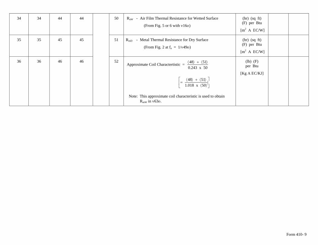
Form 410- 9
34 34 44 44 50 RaW - Air Film Thermal Resistance for Wetted Surface
(From Fig. 5 or 6 with ν16ο)
(hr) (sq ft) (F) per Btu
[m2 Α ΕC/W]
35 35 45 45 51 RmD - Metal Thermal Resistance for Dry Surface
(From Fig. 2 at fa = 1/ν49ο)
(hr) (sq ft) (F) per Btu
[m2 Α ΕC/W]
36 36 46 46 52 Approximate Coil Charactertistic =
50x243.05148 ⟩⟨+⟩⟨
⎥⎦
⎤⎢⎣
⎡⟩⟨⟩⟨+⟩⟨
=50x018.15148
Note: This approximate coil characteristic is used to obtain RmW in ν63ο.
(lb) (F) per Btu
[Kg Α ΕC/KJ]
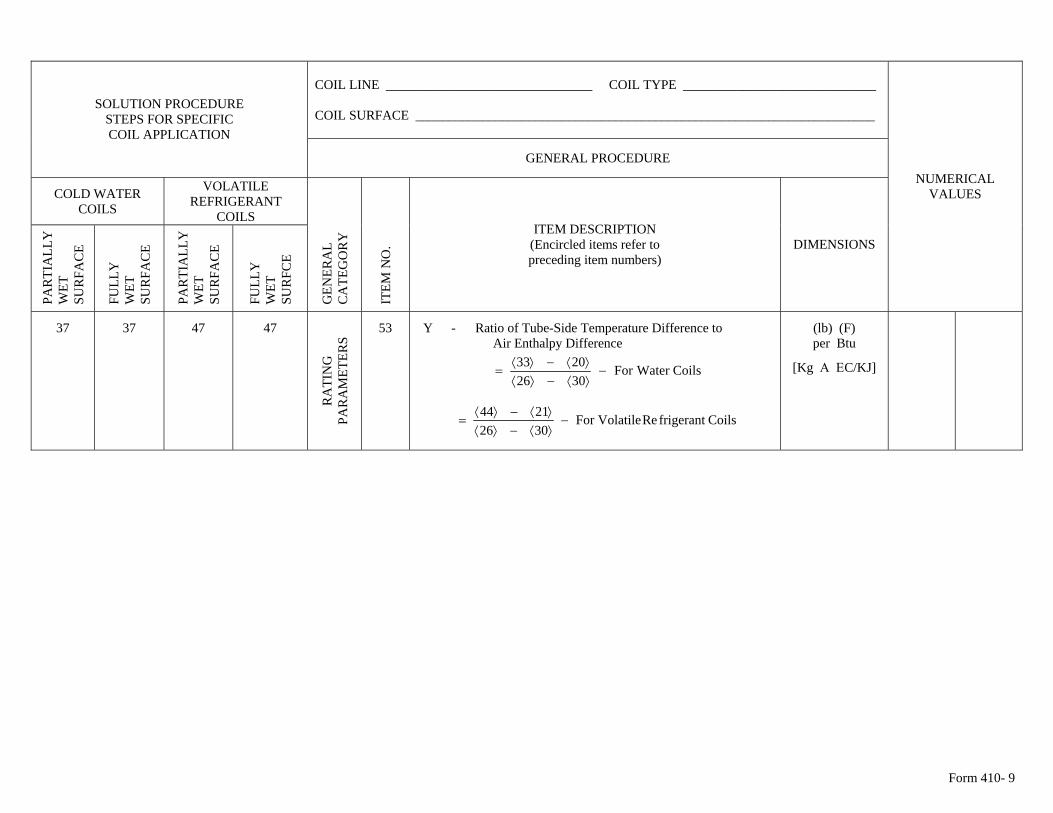
Form 410- 9
COIL LINE _______________________________ COIL TYPE _____________________________ COIL SURFACE _____________________________________________________________________
SOLUTION PROCEDURE STEPS FOR SPECIFIC COIL APPLICATION
GENERAL PROCEDURE
COLD WATER COILS
VOLATILE REFRIGERANT
COILS
PA
RTI
ALL
Y
WET
S
UR
FAC
E
FU
LLY
W
ET
SU
RFA
CE
PA
RTI
ALL
Y
WET
S
UR
FAC
E
FU
LLY
W
ET
SU
RFC
E
GEN
ERA
L C
ATE
GO
RY
ITE
M N
O.
ITEM DESCRIPTION (Encircled items refer to preceding item numbers)
DIMENSIONS
NUMERICAL VALUES
37 37 47 47 R
ATI
NG
PA
RA
MET
ERS
53 Y - Ratio of Tube-Side Temperature Difference to Air Enthalpy Difference
CoilsWaterFor30262033
−⟩⟨−⟩⟨⟩⟨−⟩⟨
=
CoilsfrigerantReVolatileFor30262144
−⟩⟨−⟩⟨⟩⟨−⟩⟨
=
(lb) (F) per Btu
[Kg Α ΕC/KJ]
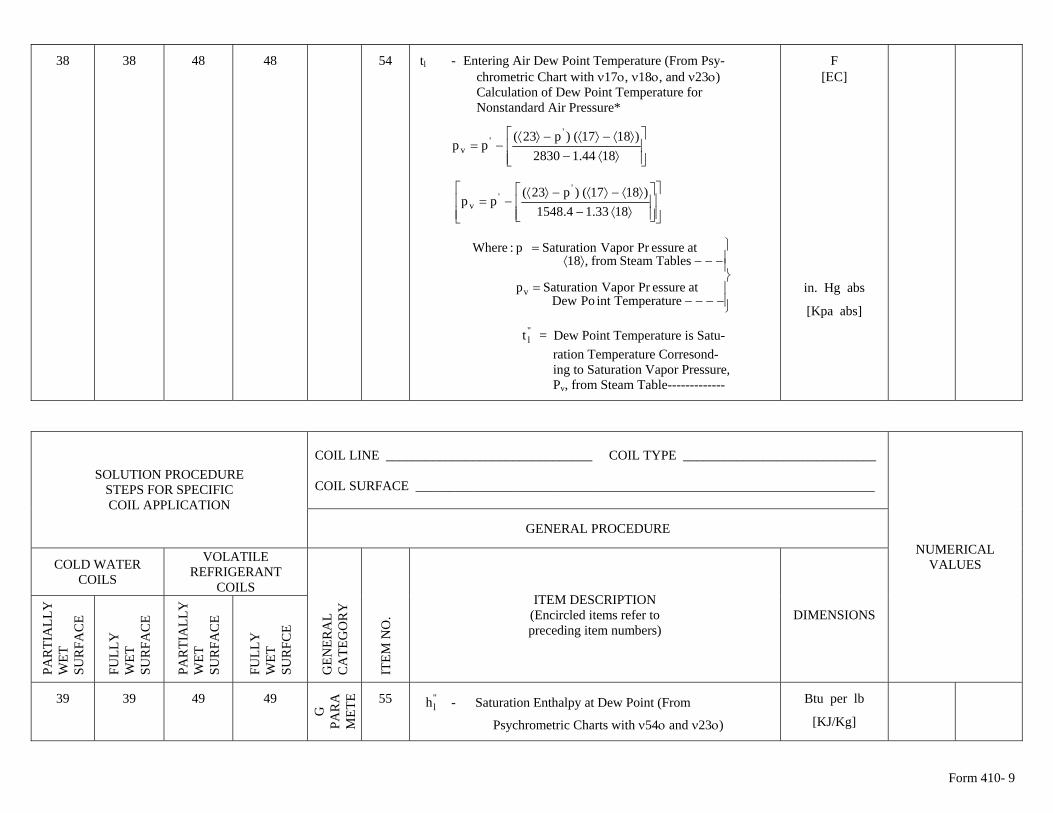
Form 410- 9
38 38 48 48 54 tl - Entering Air Dew Point Temperature (From Psy- chrometric Chart with ν17ο, ν18ο, and ν23ο) Calculation of Dew Point Temperature for Nonstandard Air Pressure*
⎥⎥⎦
⎤
⎢⎢⎣
⎡
⟩⟨−⟩⟨−⟩⟨−⟩⟨
−=1844.12830
)1817()p23(pp
''
v
⎥⎥⎦
⎤
⎢⎢⎣
⎡
⎥⎥⎦
⎤
⎢⎢⎣
⎡
⟩⟨−⟩⟨−⟩⟨−⟩⟨
−=1833.14.1548
)1817()p23(pp
''
v
⎪⎪⎭
⎪⎪⎬
⎫
−−−−=
−−−⟩⟨=
eTemperaturintPoDewatessurePrVaporSaturationp
TablesSteamfrom,18atessurePrVaporSaturationp:Where
v
= Dew Point Temperature is Satu- "lt
ration Temperature Corresond- ing to Saturation Vapor Pressure, Pv, from Steam Table-------------
F [ΕC]
in. Hg abs
[Kpa abs]
COIL LINE _______________________________ COIL TYPE _____________________________ COIL SURFACE _____________________________________________________________________
SOLUTION PROCEDURE STEPS FOR SPECIFIC COIL APPLICATION
GENERAL PROCEDURE
COLD WATER COILS
VOLATILE REFRIGERANT
COILS
PA
RTI
ALL
Y
WET
S
UR
FAC
E
FU
LLY
W
ET
SU
RFA
CE
PA
RTI
ALL
Y
WET
S
UR
FAC
E
FU
LLY
W
ET
GEN
ERA
L C
ATE
GO
RY
ITE
M N
O.
ITEM DESCRIPTION (Encircled items refer to preceding item numbers)
DIMENSIONS
NUMERICAL VALUES
SU
RFC
E
39 39 49 49
G
PAR
AM
ETE 55 - Saturation Enthalpy at Dew Point (From "
lh
Psychrometric Charts with ν54ο and ν23ο)
Btu per lb
[KJ/Kg]
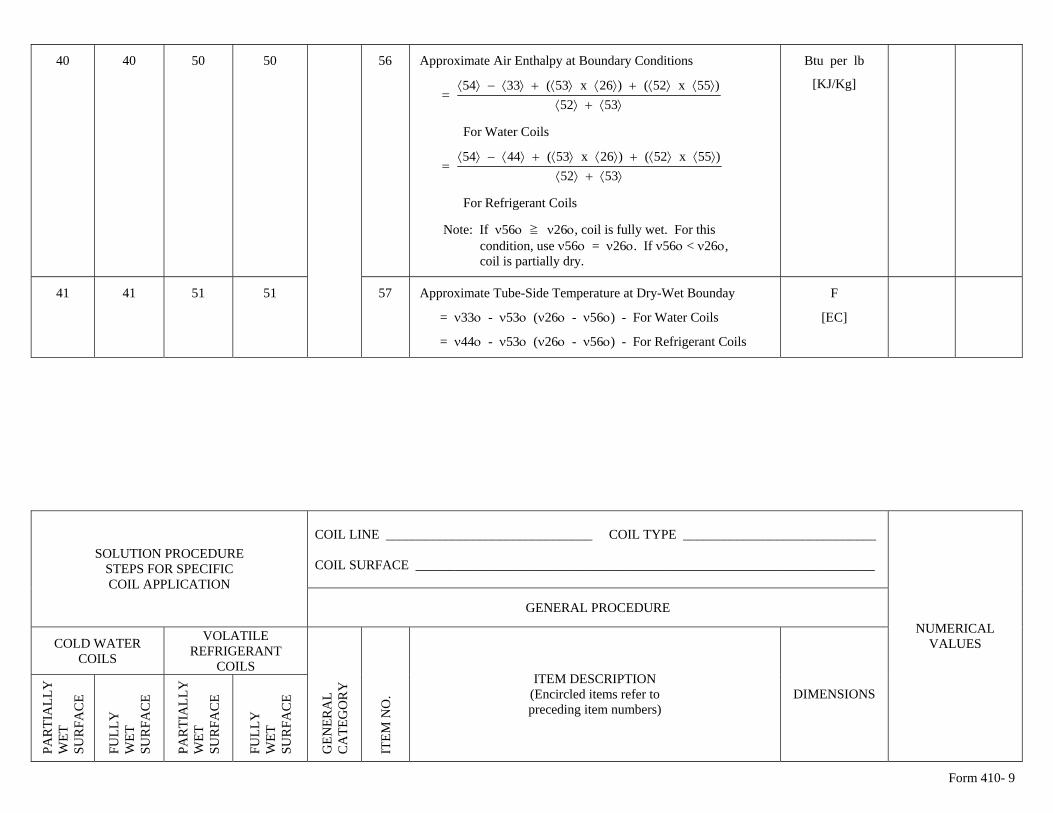
Form 410- 9
Btu per lb 40 40 50 50 56 Approximate Air Enthalpy at Boundary Conditions
⟩⟨+⟩⟨
⟩⟨⟩⟨+⟩⟨⟩⟨+⟩⟨−⟩⟨=
5352)55x52()26x53(3354
For Water Coils
⟩⟨+⟩⟨
⟩⟨⟩⟨+⟩⟨⟩⟨+⟩⟨−⟩⟨=
5352)55x52()26x53(4454
For Refrigerant Coils
Note: If ν56ο ≧ ν26ο, coil is fully wet. For this condition, use ν56ο = ν26ο. If ν56ο < ν26ο,
[KJ/Kg]
coil is partially dry.
41 41 51 51 57 Approximate Tube-Side Temperature at Dry-Wet Bounday
= ν33ο - ν53ο (ν26ο - ν56ο) - For Water Coils
= ν44ο - ν53ο (ν26ο - ν56ο) - For Refrigerant Coils
F
[ΕC]
COIL LINE _______________________________ COIL TYPE _____________________________ COIL SURFACE _____________________________________________________________________
SOLUTION PROCEDURE STEPS FOR SPECIFIC COIL APPLICATION
GENERAL PROCEDURE
COLD WATER COILS
VOLATILE REFRIGERANT
COILS
PA
RTI
ALL
Y
WET
S
UR
FAC
E
FU
LLY
W
ET
SU
RFA
CE
PA
RTI
ALL
Y
WET
S
UR
FAC
E
FU
LLY
W
ET
SU
RFA
CE
GEN
ERA
L C
ATE
GO
RY
ITE
M N
O.
ITEM DESCRIPTION (Encircled items refer to preceding item numbers)
DIMENSIONS
NUMERICAL VALUES
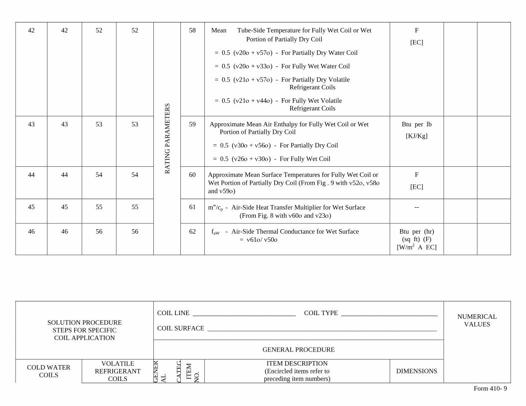
Form 410- 9
42 42 52 52 58 Mean Tube-Side Temperature for Fully Wet Coil or Wet Portion of Partially Dry Coil
= 0.5 (ν20ο + ν57ο) - For Partially Dry Water Coil
= 0.5 (ν20ο + ν33ο) - For Fully Wet Water Coil
= 0.5 (ν21ο + ν57ο) - For Partially Dry Volatile Refrigerant Coils
= 0.5 (ν21ο + ν44ο) - For Fully Wet Volatile Refrigerant Coils
F
[ΕC]
43 43 53 53 59 Approximate Mean Air Enthalpy for Fully Wet Coil or Wet Portion of Partially Dry Coil
= 0.5 (ν30ο + ν56ο) - For Partially Dry Coil
= 0.5 (ν26ο + ν30ο) - For Fully Wet Coil
Btu per lb
[KJ/Kg]
44 44 54 54 60 Approximate Mean Surface Temperatures for Fully Wet Coil or Wet Portion of Partially Dry Coil (From Fig . 9 with ν52ο, ν58ο and ν59ο)
F
[ΕC]
45 45 55 55 61 m"/cp - Air-Side Heat Transfer Multiplier for Wet Surface (From Fig. 8 with ν60ο and ν23ο)
--
46 46 56 56
RA
TIN
G P
AR
AM
ETER
S
62 faW - Air-Side Thermal Conductance for Wet Surface = ν61ο/ ν50ο
Btu per (hr) (sq ft) (F)
[W/m2 Α ΕC]
COIL LINE _______________________________ COIL TYPE _____________________________ COIL SURFACE _____________________________________________________________________
SOLUTION PROCEDURE STEPS FOR SPECIFIC COIL APPLICATION
GENERAL PROCEDURE
COLD WATER COILS
VOLATILE REFRIGERANT
COILS GEN
ERA
L C
ATE
G I
TEM
N
O.
ITEM DESCRIPTION (Encircled items refer to preceding item numbers)
DIMENSIONS
NUMERICAL VALUES
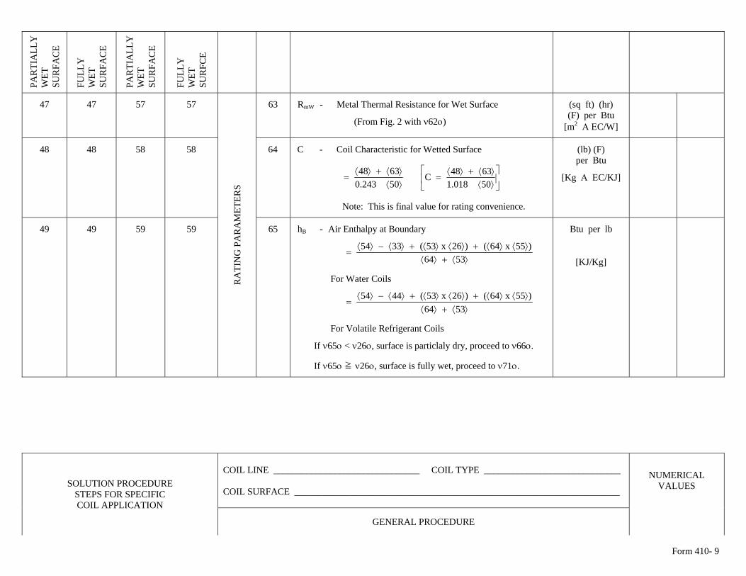
Form 410- 9
PA
RTI
ALL
Y
WET
S
UR
FAC
E
FU
LLY
W
ET
SU
RFA
CE
PA
RTI
ALL
Y
WET
S
UR
FAC
E
FU
LLY
W
ET
SU
RFC
E
47 47 57 57 63 RmW - Metal Thermal Resistance for Wet Surface
(From Fig. 2 with ν62ο)
(sq ft) (hr) (F) per Btu
[m2 Α ΕC/W]
48 48 58 58 64 C - Coil Characteristic for Wetted Surface
⟩⟨⟩⟨+⟩⟨
=50243.06348 ⎥
⎦
⎤⎢⎣
⎡⟩⟨⟩⟨+⟩⟨
=50018.16348C
Note: This is final value for rating convenience.
(lb) (F) per Btu
[Kg Α ΕC/KJ]
49 49 59 59 R
ATI
NG
PA
RA
MET
ERS
65 hB - Air Enthalpy at Boundary
⟩⟨+⟩⟨
⟩⟨⟩⟨+⟩⟨⟩⟨+⟩⟨−⟩⟨=
5364)55x64()26x53(3354
For Water Coils
⟩⟨+⟩⟨
⟩⟨⟩⟨+⟩⟨⟩⟨+⟩⟨−⟩⟨=
5364)55x64()26x53(4454
For Volatile Refrigerant Coils
If ν65ο < ν26ο, surface is particlaly dry, proceed to ν66ο.
If ν65ο ≧ ν26ο, surface is fully wet, proceed to ν71ο.
Btu per lb
[KJ/Kg]
COIL LINE _______________________________ COIL TYPE _____________________________ COIL SURFACE _____________________________________________________________________
SOLUTION PROCEDURE STEPS FOR SPECIFIC COIL APPLICATION
GENERAL PROCEDURE
NUMERICAL VALUES
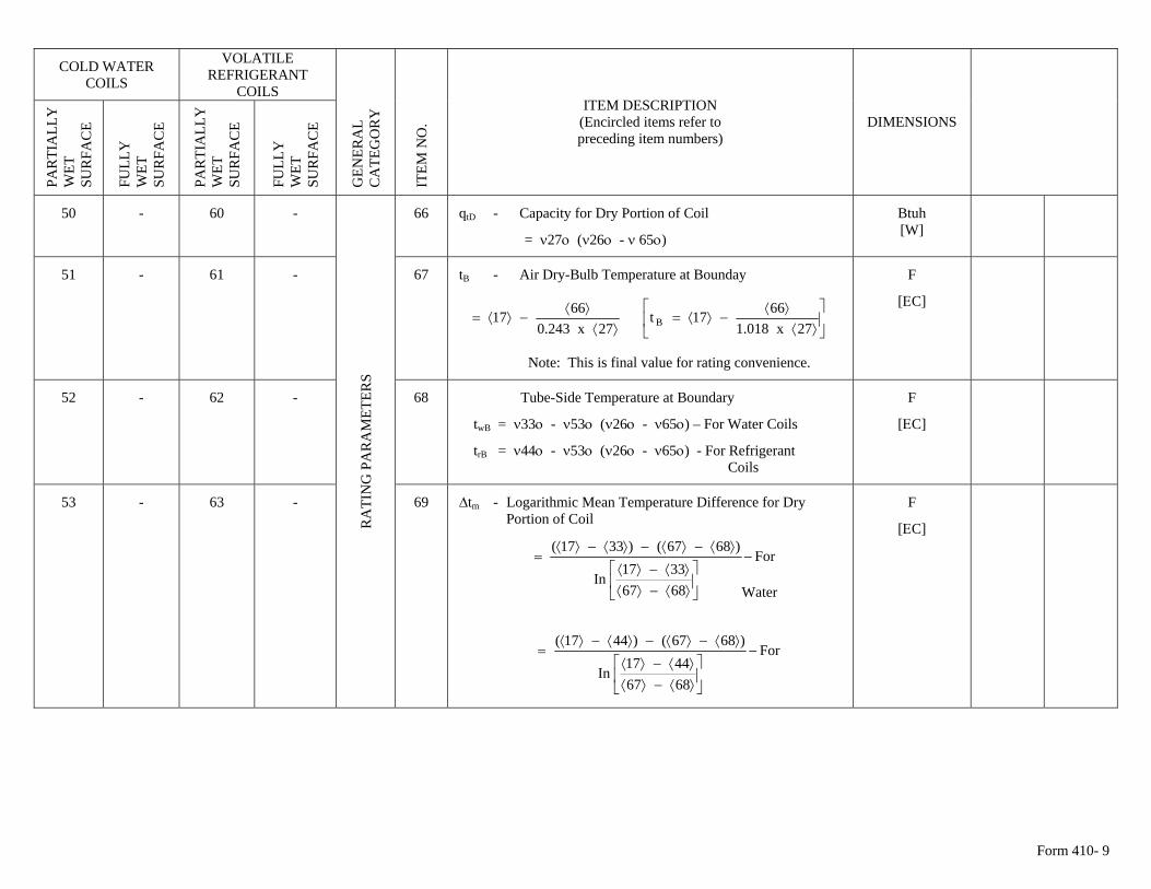
Form 410- 9
COLD WATER COILS
VOLATILE REFRIGERANT
COILS
PA
RTI
ALL
Y
WET
S
UR
FAC
E
FU
LLY
W
ET
SU
RFA
CE
PA
RTI
ALL
Y
WET
S
UR
FAC
E
FU
LLY
W
ET
SU
RFA
CE
GEN
ERA
L C
ATE
GO
RY
ITE
M N
O.
ITEM DESCRIPTION (Encircled items refer to preceding item numbers)
DIMENSIONS
50 - 60 - 66 qtD - Capacity for Dry Portion of Coil
= ν27ο (ν26ο - ν 65ο)
Btuh [W]
51 - 61 - 67 tB - Air Dry-Bulb Temperature at Bounday
⟩⟨
⟩⟨−⟩⟨=
27x243.06617 ⎥
⎦
⎤⎢⎣
⎡⟩⟨
⟩⟨−⟩⟨=
27x018.16617t B
Note: This is final value for rating convenience.
F
[ΕC]
52 - 62 - 68 Tube-Side Temperature at Boundary
twB = ν33ο - ν53ο (ν26ο - ν65ο) – For Water Coils
trB = ν44ο - ν53ο (ν26ο - ν65ο) - For Refrigerant Coils
F
[ΕC]
53 - 63 -
RA
TIN
G P
AR
AM
ETER
S
69 ∆tm - Logarithmic Mean Temperature Difference for Dry Portion of Coil
Water
For
68673317
In
)6867()3317(−
⎥⎦
⎤⎢⎣
⎡⟩⟨−⟩⟨⟩⟨−⟩⟨
⟩⟨−⟩⟨−⟩⟨−⟩⟨=
F
[ΕC]
For
68674417
In
)6867()4417(−
⎥⎦
⎤⎢⎣
⎡⟩⟨−⟩⟨⟩⟨−⟩⟨
⟩⟨−⟩⟨−⟩⟨−⟩⟨=
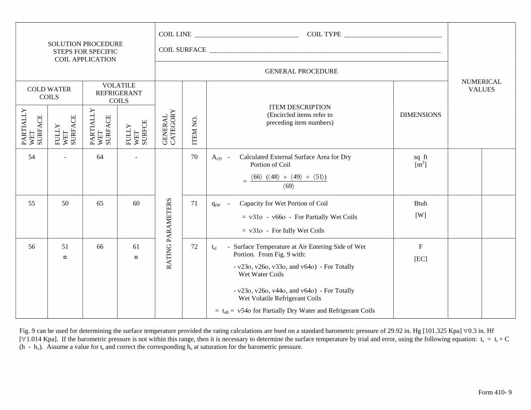
Form 410- 9
COIL LINE _______________________________ COIL TYPE _____________________________ COIL SURFACE _____________________________________________________________________
SOLUTION PROCEDURE STEPS FOR SPECIFIC COIL APPLICATION
GENERAL PROCEDURE
COLD WATER COILS
VOLATILE REFRIGERANT
COILS
PA
RTI
ALL
Y
WET
S
UR
FAC
E
FU
LLY
W
ET
SU
RFA
CE
PA
RTI
ALL
Y
WET
S
UR
FAC
E
FU
LLY
W
ET
SU
RFC
E
GEN
ERA
L C
ATE
GO
RY
ITE
M N
O.
ITEM DESCRIPTION (Encircled items refer to preceding item numbers)
DIMENSIONS
NUMERICAL VALUES
54 - 64 - 70 AcD - Calculated External Surface Area for Dry Portion of Coil
⟩⟨
⟩⟨+⟩⟨+⟩⟨⟩⟨=
69)514948(66
sq ft [m2]
55 50 65 60 71 qtW - Capacity for Wet Portion of Coil
= ν31ο - ν66ο - For Partially Wet Coils
= ν31ο - For fully Wet Coils
Btuh
[W]
56 51 ¤
66 61
RA
TIN
G P
AR
AM
ETER
S
72 tsl - Surface Temperature at Air Entering Side of Wet Portion. From Fig. 9 with: ¤ - ν23ο, ν26ο, ν33ο, and ν64ο) - For Totally Wet Water Coils
- ν23ο, ν26ο, ν44ο, and ν64ο) - For Totally Wet Volatile Refrigerant Coils
= tsB = ν54ο for Partially Dry Water and Refrigerant Coils
F
[ΕC]
Fig. 9 can be used for determining the surface temperature provided the rating calculations are bsed on a standard barometric pressure of 29.92 in. Hg [101.325 Kpa] ∀0.3 in. Hf [∀1.014 Kpa]. If the barometric pressure is not within this range, then it is necessary to determine the surface temperature by trial and error, using the following equation: ts = tt + C (h - hx). Assume a value for ts and correct the corresponding hs at saturation for the barometric pressure.
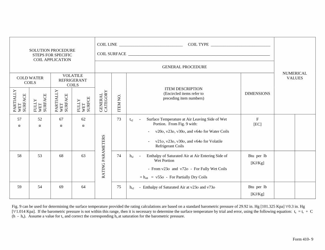
Form 410- 9
COIL LINE _______________________________ COIL TYPE _____________________________ COIL SURFACE _____________________________________________________________________
SOLUTION PROCEDURE STEPS FOR SPECIFIC COIL APPLICATION
GENERAL PROCEDURE
COLD WATER COILS
VOLATILE REFRIGERANT
COILS
PA
RTI
ALL
Y
WET
S
UR
FAC
E
FU
LLY
W
ET
SU
RFA
CE
PA
RTI
ALL
Y
WET
S
UR
FAC
E
FU
LLY
W
ET
SU
RFC
E
GEN
ERA
L C
ATE
GO
RY
ITE
M N
O.
ITEM DESCRIPTION (Encircled items refer to preceding item numbers)
DIMENSIONS
NUMERICAL VALUES
57 ¤
52 ¤
67 ¤
62 ¤
73 ts2 - Surface Temperature at Air Leaving Side of Wet Portion. From Fig. 9 with:
- ν20ο, ν23ο, ν30ο, and ν64ο for Water Coils
- ν21ο, ν23ο, ν30ο, and ν64ο for Volatile Refrigerant Coils
F [ΕC]
58 53 68 63 74 hsl - Enthalpy of Saturated Air at Air Entering Side of Wet Portion
- From ν23ο and ν72ο - For Fully Wet Coils
= hsB = ν55ο - For Partially Dry Coils
Btu per lb
[KJ/Kg]
59 54 69 64
RA
TIN
G P
AR
AM
ETER
S
75 hs2 - Enthalpy of Saturated Air at ν23ο and ν73ο Btu per lb
[KJ/Kg]
Fig. 9 can be used for determining the surface temperature provided the rating calculations are based on a standard barometric pressure of 29.92 in. Hg [101.325 Kpa] ∀0.3 in. Hg [∀1.014 Kpa]. If the barometric pressure is not within this range, then it is necessary to determine the surface temperature by trial and error, using the following equation: ts = tr + C (h - hs). Assume a value for tx and correct the corresponding hs at saturation for the barometric pressure.
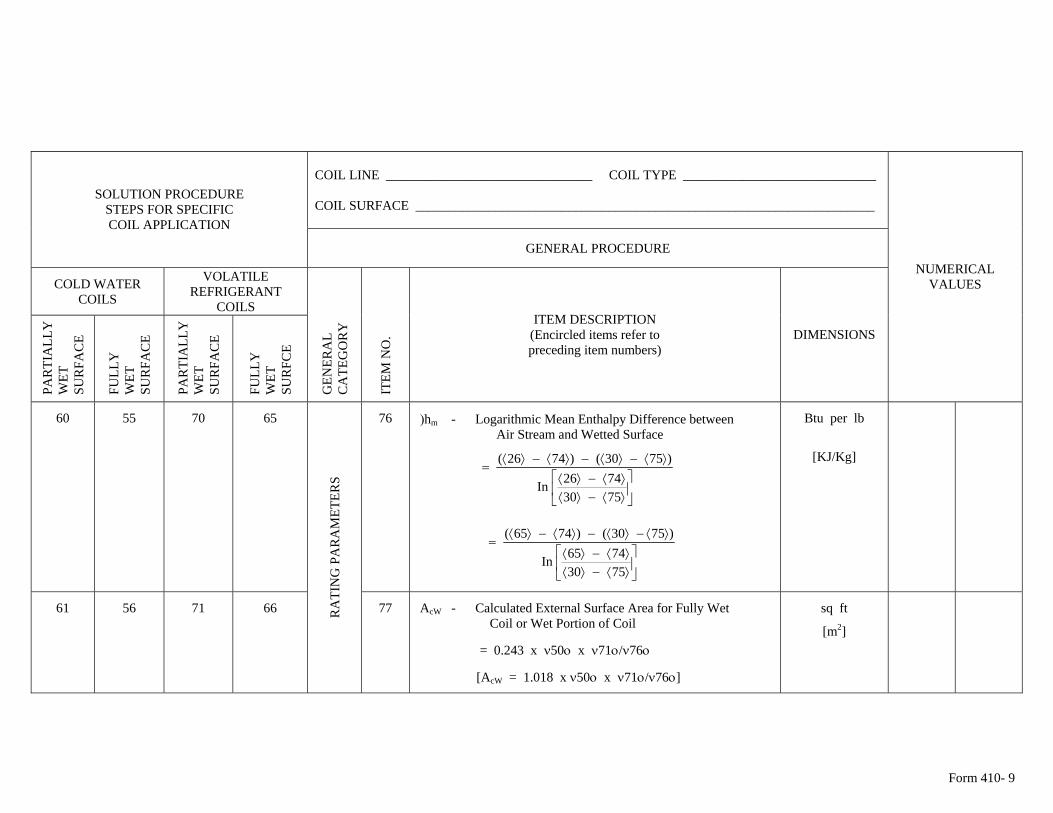
Form 410- 9
COIL LINE _______________________________ COIL TYPE _____________________________ COIL SURFACE _____________________________________________________________________
SOLUTION PROCEDURE STEPS FOR SPECIFIC COIL APPLICATION
GENERAL PROCEDURE
COLD WATER COILS
VOLATILE REFRIGERANT
COILS
PA
RTI
ALL
Y
WET
S
UR
FAC
E
FU
LLY
W
ET
SU
RFA
CE
PA
RTI
ALL
Y
WET
S
UR
FAC
E
FU
LLY
W
ET
SU
RFC
E
GEN
ERA
L C
ATE
GO
RY
ITE
M N
O.
ITEM DESCRIPTION (Encircled items refer to preceding item numbers)
DIMENSIONS
NUMERICAL VALUES
60 55 70 65 76 )hm - Logarithmic Mean Enthalpy Difference between Air Stream and Wetted Surface
⎥⎦
⎤⎢⎣
⎡⟩⟨−⟩⟨⟩⟨−⟩⟨
⟩⟨−⟩⟨−⟩⟨−⟩⟨=
75307426In
)7530()7426(
⎥⎦
⎤⎢⎣
⎡⟩⟨−⟩⟨⟩⟨−⟩⟨
⟩⟨−⟩⟨−⟩⟨−⟩⟨=
75307465In
)7530()7465(
Btu per lb
[KJ/Kg]
61 56 71 66 RA
TIN
G P
AR
AM
ETER
S
77 AcW - Calculated External Surface Area for Fully Wet Coil or Wet Portion of Coil
= 0.243 x ν50ο x ν71ο/ν76ο
[AcW = 1.018 x ν50ο x ν71ο/ν76ο]
sq ft
[m2]
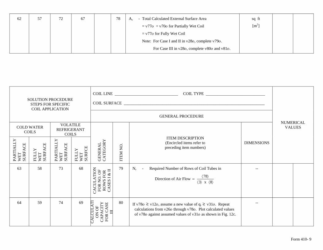
Form 410- 9
78 Ac - Total Calculated External Surface Area
= ν77ο + ν70ο for Partially Wet Coil
= ν77ο for Fully Wet Coil
Note: For Case I and II in ν28ο, complete ν79ο.
For Case III in ν28ο, complete ν80ο and ν81ο.
sq ft
[m2]
62 57 72 67
COIL LINE _______________________________ COIL TYPE _____________________________ COIL SURFACE _____________________________________________________________________
SOLUTION PROCEDURE STEPS FOR SPECIFIC COIL APPLICATION
GENERAL PROCEDURE
COLD WATER COILS
VOLATILE REFRIGERANT
COILS
PA
RTI
ALL
Y
WET
S
UR
FAC
E
FU
LLY
W
ET
SU
RFA
CE
PA
RTI
ALL
Y
WET
S
UR
FAC
E
FU
LLY
W
ET
SU
RFC
E
GEN
ERA
L C
ATE
GO
RY
ITE
M N
O.
ITEM DESCRIPTION (Encircled items refer to preceding item numbers)
DIMENSIONS
NUMERICAL VALUES
63 58 73 68
CA
CU
LATI
ON
FO
R N
O. O
F R
OW
S FO
R
CA
SES
I & II
79 Nr - Required Number of Rows of Coil Tubes in
Direction of Air Flow ⟩⟨⟩⟨
⟩⟨=
8x378
--
64 59 74 69
CA
LCU
LATI
ON
OF
CA
PAC
ITY
FO
R C
ASE
II
I
80 If ν78ο ≷ ν12ο, assume a new value of qt ≷ ν31ο. Repeat calculations from ν26ο through ν78ο. Plot calculated values of ν78ο against assumed values of ν31ο as shown in Fig. 12c.
--
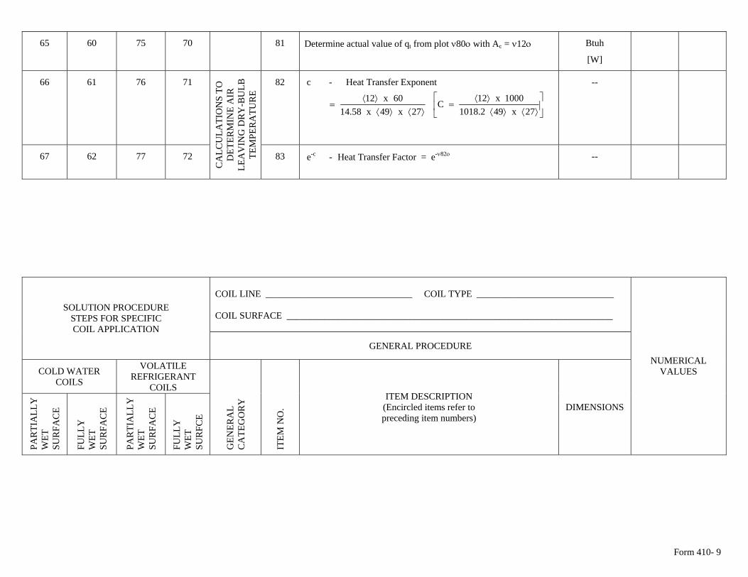
Form 410- 9
65 60 75 70 81 Determine actual value of qt from plot ν80ο with Ac = ν12ο Btuh
[W]
66 61 76 71 82 c - Heat Transfer Exponent --
⟩⟨⟩⟨
⟩⟨=
27x49x58.1460x12 ⎥
⎦
⎤⎢⎣
⎡⟩⟨⟩⟨
⟩⟨=
27x492.10181000x12C
67 62 77 72
CA
LCU
LATI
ON
S TO
D
ETER
MIN
E A
IR
LEA
VIN
G D
RY
-BU
LB
TEM
PER
ATU
RE
83 e-c - Heat Transfer Factor = e-ν82ο
--
COIL LINE _______________________________ COIL TYPE _____________________________ COIL SURFACE _____________________________________________________________________
SOLUTION PROCEDURE STEPS FOR SPECIFIC COIL APPLICATION
GENERAL PROCEDURE
COLD WATER COILS
VOLATILE REFRIGERANT
COILS
PA
RTI
ALL
Y
WET
S
UR
FAC
E
FU
LLY
W
ET
SU
RFA
CE
PA
RTI
ALL
Y
WET
S
UR
FAC
E
FU
LLY
W
ET
SU
RFC
E
GEN
ERA
L C
ATE
GO
RY
ITE
M N
O.
ITEM DESCRIPTION (Encircled items refer to preceding item numbers)
DIMENSIONS
NUMERICAL VALUES
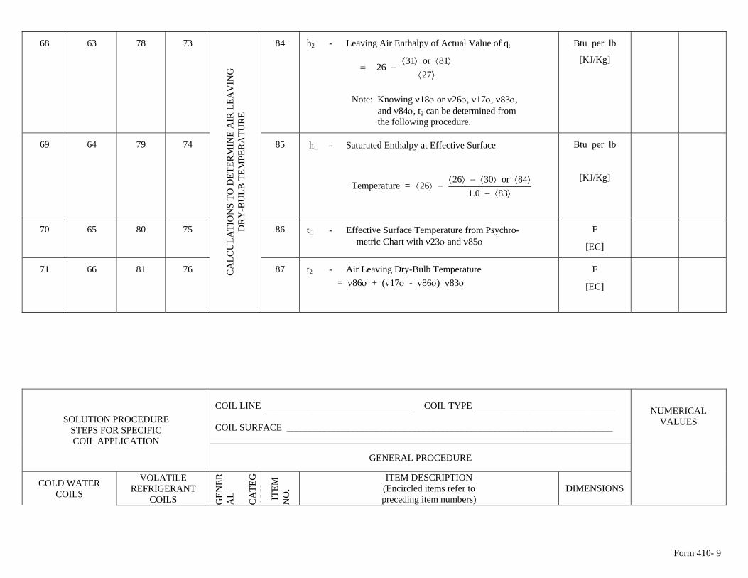
Form 410- 9
68 63 78 73 84 h2 - Leaving Air Enthalpy of Actual Value of qt
⟩⟨
⟩⟨⟩⟨−=
2781or31
26
Note: Knowing ν18ο or ν26ο, ν17ο, ν83ο, and ν84ο, t2 can be determined from the following procedure.
Btu per lb
[KJ/Kg]
69 64 79 74 85 h - Saturated Enthalpy at Effective Surface
Temperature = ⟩⟨−
⟩⟨⟩⟨−⟩⟨−⟩⟨
830.184or3026
26
Btu per lb
[KJ/Kg]
70 65 80 75 86 t - Effective Surface Temperature from Psychro- metric Chart with ν23ο and ν85ο
F
[ΕC]
71 66 81 76 CA
LCU
LATI
ON
S TO
DET
ERM
INE
AIR
LEA
VIN
G
DR
Y-B
ULB
TEM
PER
ATU
RE
87 t2 - Air Leaving Dry-Bulb Temperature = ν86ο + (ν17ο - ν86ο) ν83ο
F
[ΕC]
COIL LINE _______________________________ COIL TYPE _____________________________ COIL SURFACE _____________________________________________________________________
SOLUTION PROCEDURE STEPS FOR SPECIFIC COIL APPLICATION
GENERAL PROCEDURE
COLD WATER COILS
VOLATILE REFRIGERANT
COILS GEN
ERA
L C
ATE
GO
RY
ITE
M
NO
.
ITEM DESCRIPTION (Encircled items refer to preceding item numbers)
DIMENSIONS
NUMERICAL VALUES
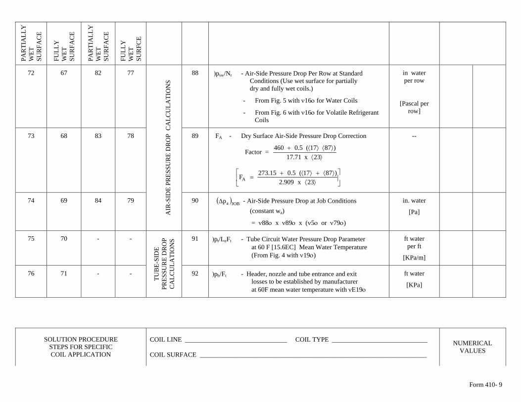
Form 410- 9
PA
RTI
ALL
Y
WET
S
UR
FAC
E
FU
LLY
W
ET
SU
RFA
CE
PA
RTI
ALL
Y
WET
S
UR
FAC
E
FU
LLY
W
ET
SU
RFC
E
72 67 82 77 88 )psw/Nr - Air-Side Pressure Drop Per Row at Standard Conditions (Use wet surface for partially dry and fully wet coils.)
- From Fig. 5 with ν16ο for Water Coils
- From Fig. 6 with ν16ο for Volatile Refrigerant Coils
in water per row
[Pascal per row]
73 68 83 78 89 FA - Dry Surface Air-Side Pressure Drop Correction
Factor = ⟩⟨
⟩⟨⟩⟨+23x71.17
)8717(5.0460
⎥⎦
⎤⎢⎣
⎡⟩⟨
⟩⟨+⟩⟨+=
23x909.2)8717(5.015.273FA
--
74 69 84 79
A
IR-S
IDE
PRES
SUR
E D
RO
P C
ALC
ULA
TIO
NS
90 ( )JOBapΔ - Air-Side Pressure Drop at Job Conditions (constant wa)
= ν88ο x ν89ο x (ν5ο or ν79ο)
in. water
[Pa]
75 70 - - 91 )pt/LeFt - Tube Circuit Water Pressure Drop Parameter at 60 F [15.6ΕC] Mean Water Temperature (From Fig. 4 with ν19ο)
ft water per ft
[KPa/m]
76 71 - -
TUB
E-SI
DE
PRES
SUR
E D
RO
P C
ALC
ULA
TIO
NS
ft water 92 )ph/Ft - Header, nozzle and tube entrance and exit losses to be established by manufacturer at 60F mean water temperature with νΕ19ο
[KPa]
SOLUTION PROCEDURE STEPS FOR SPECIFIC COIL APPLICATION
COIL LINE _______________________________ COIL TYPE _____________________________ COIL SURFACE _____________________________________________________________________
NUMERICAL VALUES
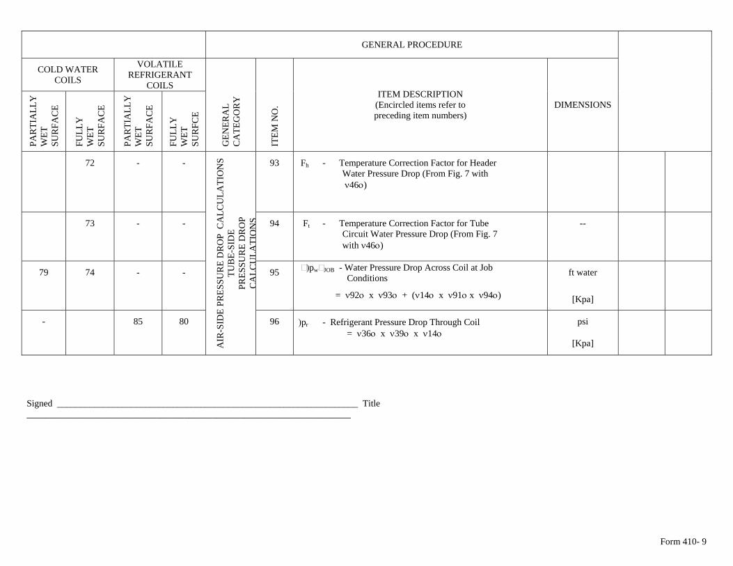
Form 410- 9
GENERAL PROCEDURE
COLD WATER COILS
VOLATILE REFRIGERANT
COILS
PA
RTI
ALL
Y
WET
S
UR
FAC
E
FU
LLY
W
ET
SU
RFA
CE
PA
RTI
ALL
Y
WET
S
UR
FAC
E
FU
LLY
W
ET
SU
RFC
E
GEN
ERA
L C
ATE
GO
RY
ITE
M N
O.
ITEM DESCRIPTION (Encircled items refer to preceding item numbers)
DIMENSIONS
72 - - 93 Fh - Temperature Correction Factor for Header Water Pressure Drop (From Fig. 7 with ν46ο)
73 - - 94 Ft - Temperature Correction Factor for Tube Circuit Water Pressure Drop (From Fig. 7 with ν46ο)
--
79 74 - - 95 )pw JOB - Water Pressure Drop Across Coil at Job Conditions
= ν92ο x ν93ο + (ν14ο x ν91ο x ν94ο)
ft water
[Kpa]
- 85 80
A
IR-S
IDE
PRES
SUR
E D
RO
P C
ALC
ULA
TIO
NS
TUB
E-SI
DE
PRES
SUR
E D
RO
P C
ALC
ULA
TIO
NS
96 )pr - Refrigerant Pressure Drop Through Coil = ν36ο x ν39ο x ν14ο
psi
[Kpa]
Signed _________________________________________________________________ Title ______________________________________________________________________
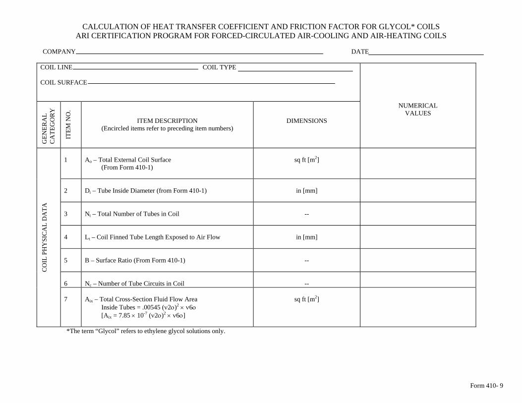
Form 410- 9
CALCULATION OF HEAT TRANSFER COEFFICIENT AND FRICTION FACTOR FOR GLYCOL* COILS ARI CERTIFICATION PROGRAM FOR FORCED-CIRCULATED AIR-COOLING AND AIR-HEATING COILS
COMPANY DATE
COIL LINE COIL TYPE COIL SURFACE
GEN
ERA
L C
ATE
GO
RY
ITEM
NO
.
ITEM DESCRIPTION (Encircled items refer to preceding item numbers)
DIMENSIONS
NUMERICAL VALUES
1
Ao – Total External Coil Surface (From Form 410-1)
sq ft [m2]
2
Di – Tube Inside Diameter (from Form 410-1)
in [mm]
3
Nt – Total Number of Tubes in Coil
--
4
Lt – Coil Finned Tube Length Exposed to Air Flow
in [mm]
5
B – Surface Ratio (From Form 410-1)
--
6
Nc – Number of Tube Circuits in Coil
--
CO
IL P
HY
SIC
AL
DA
TA
7
Aix – Total Cross-Section Fluid Flow Area Inside Tubes = .00545 (ν2ο)2 × ν6ο [Aix = 7.85 × 10⁻⁷ (ν2ο)2 × ν6ο]
sq ft [m2]
*The term “Glycol” refers to ethylene glycol solutions only.
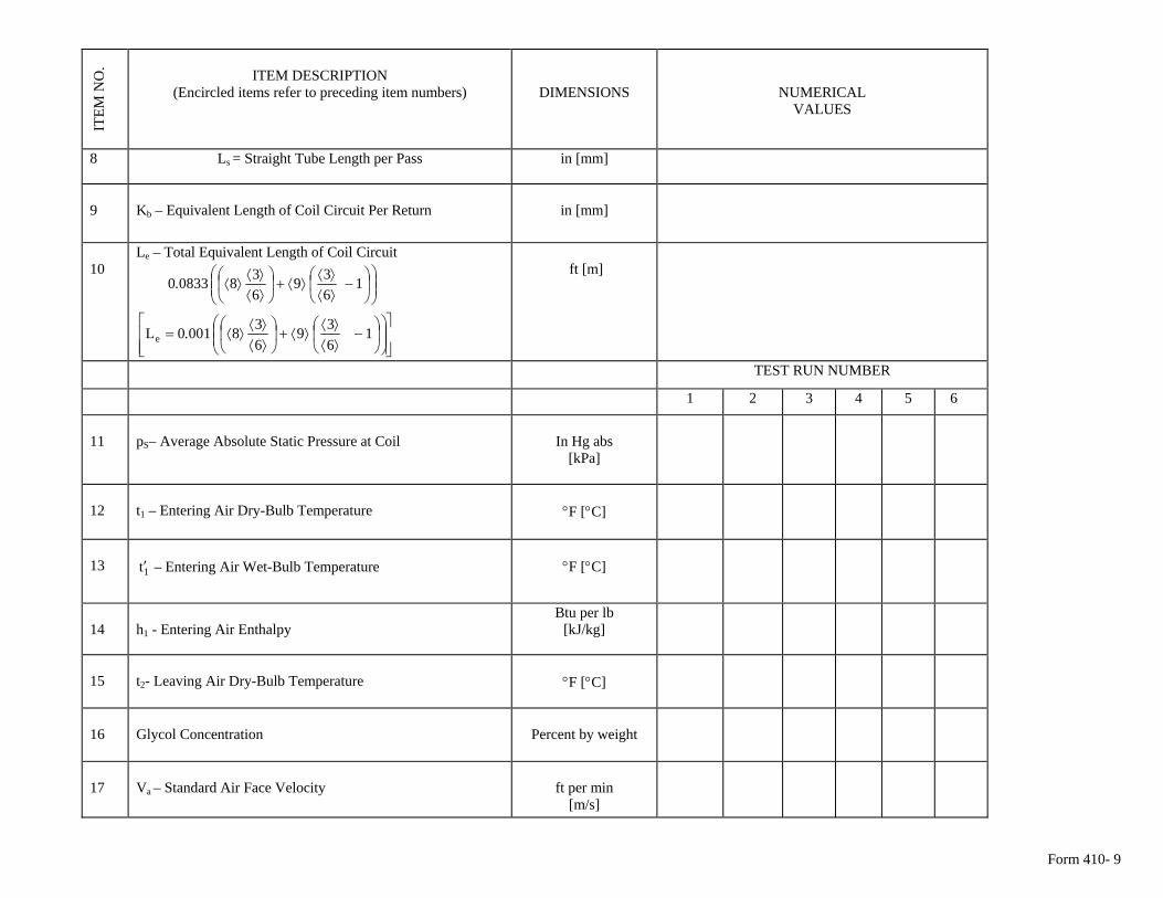
Form 410- 9
ITEM
NO
. ITEM DESCRIPTION
(Encircled items refer to preceding item numbers)
DIMENSIONS
NUMERICAL VALUES
8
Ls = Straight Tube Length per Pass in [mm]
9
Kb – Equivalent Length of Coil Circuit Per Return
in [mm]
10
Le – Total Equivalent Length of Coil Circuit
⎟⎟⎠
⎞⎜⎜⎝
⎛⎟⎠
⎞⎜⎝
⎛−
⟩⟨⟩⟨
⟩⟨+⎟⎠
⎞⎜⎝
⎛⟩⟨⟩⟨
⟩⟨ 1639
63808330.
⎥⎥⎦
⎤
⎢⎢⎣
⎡⎟⎟⎠
⎞⎜⎜⎝
⎛⎟⎠
⎞⎜⎝
⎛−
⟩⟨⟩⟨
⟩⟨+⎟⎠
⎞⎜⎝
⎛⟩⟨⟩⟨
⟩⟨= 1639
6380010Le .
ft [m]
TEST RUN NUMBER
1 2 3 4 5 6
11
pS– Average Absolute Static Pressure at Coil
In Hg abs
[kPa]
12
t1 – Entering Air Dry-Bulb Temperature
°F [°C]
13
1t′ – Entering Air Wet-Bulb Temperature
°F [°C]
14
h1 - Entering Air Enthalpy
Btu per lb [kJ/kg]
15
t2- Leaving Air Dry-Bulb Temperature
°F [°C]
16
Glycol Concentration
Percent by weight
17
Va – Standard Air Face Velocity
ft per min
[m/s]
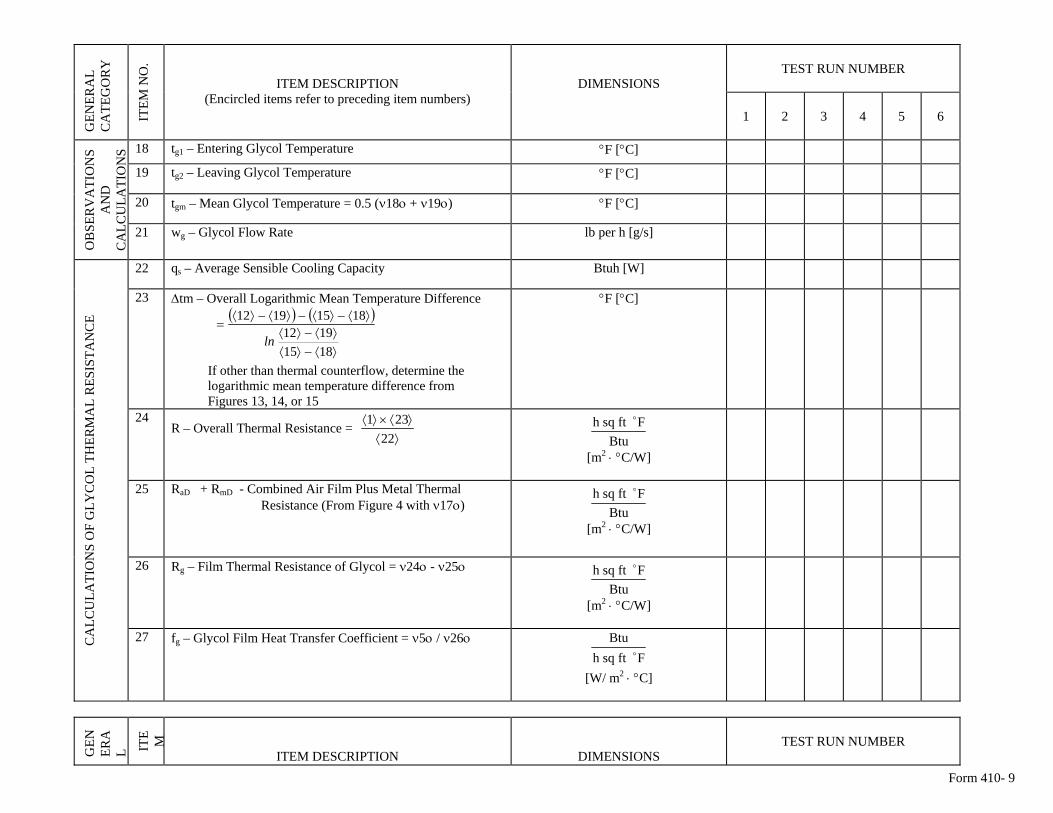
Form 410- 9
TEST RUN NUMBER G
ENER
AL
CA
TEG
OR
Y
ITEM
NO
.
ITEM DESCRIPTION (Encircled items refer to preceding item numbers)
DIMENSIONS
1 2 3 4 5 6
18 tg1 – Entering Glycol Temperature °F [°C]
19 tg2 – Leaving Glycol Temperature °F [°C]
20 tgm – Mean Glycol Temperature = 0.5 (ν18ο + ν19ο) °F [°C]
OB
SER
VA
TIO
NS
AN
D
CA
LCU
LATI
ON
S
21 wg – Glycol Flow Rate lb per h [g/s]
22 qs – Average Sensible Cooling Capacity Btuh [W]
23 Δtm – Overall Logarithmic Mean Temperature Difference ( ) ( )
⟩⟨−⟩⟨⟩⟨−⟩⟨
⟩⟨−⟩⟨−⟩⟨−⟩⟨=
18151912
18151912
ln
If other than thermal counterflow, determine the logarithmic mean temperature difference from Figures 13, 14, or 15
°F [°C]
24 R – Overall Thermal Resistance =
⟩⟨⟩⟨×⟩⟨
22231
Btu
Fftsqh o
[m2 ⋅ °C/W]
25 RaD + RmD - Combined Air Film Plus Metal Thermal Resistance (From Figure 4 with ν17ο) Btu
Fftsqh o
[m2 ⋅ °C/W]
26 Rg – Film Thermal Resistance of Glycol = ν24ο - ν25ο Btu
Fftsqh o
[m2 ⋅ °C/W]
CA
LCU
LATI
ON
S O
F G
LYC
OL
THER
MA
L R
ESIS
TAN
CE
27 fg – Glycol Film Heat Transfer Coefficient = ν5ο / ν26ο Fftsqh
Btuo
[W/ m2 ⋅ °C]
GEN
ERA
L ITE M
ITEM DESCRIPTION
DIMENSIONS TEST RUN NUMBER
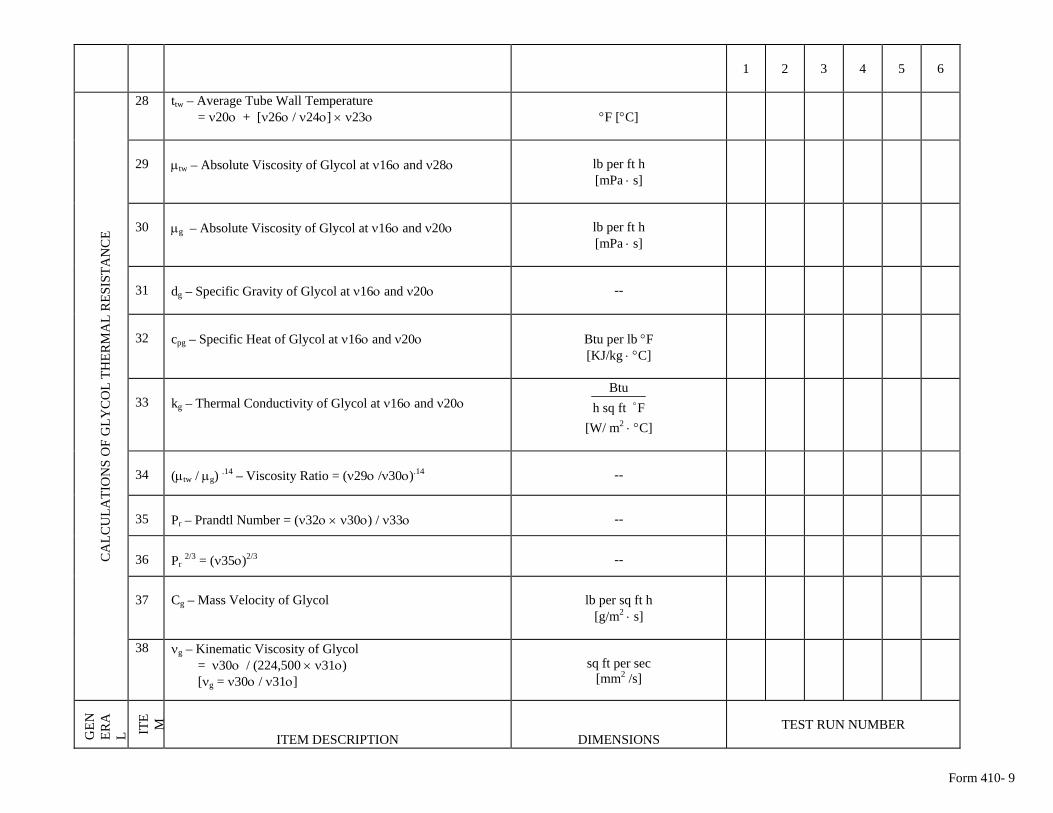
Form 410- 9
1 2 3 4 5 6
28 ttw – Average Tube Wall Temperature = ν20ο + [ν26ο / ν24ο] × ν23ο
°F [°C]
29
μtw – Absolute Viscosity of Glycol at ν16ο and ν28ο
lb per ft h [mPa ⋅ s]
30
μg – Absolute Viscosity of Glycol at ν16ο and ν20ο
lb per ft h [mPa ⋅ s]
31
dg – Specific Gravity of Glycol at ν16ο and ν20ο
--
32
cpg – Specific Heat of Glycol at ν16ο and ν20ο
Btu per lb °F [KJ/kg ⋅ °C]
33
kg – Thermal Conductivity of Glycol at ν16ο and ν20ο Fftsqh
Btuo
[W/ m2 ⋅ °C]
34
(μtw / μg) .14 – Viscosity Ratio = (ν29ο /ν30ο).14
--
35
Pr – Prandtl Number = (ν32ο × ν30ο) / ν33ο
--
36
Pr 2/3 = (ν35ο)2/3
--
37
Cg – Mass Velocity of Glycol
lb per sq ft h
[g/m2 ⋅ s]
C
ALC
ULA
TIO
NS
OF
GLY
CO
L TH
ERM
AL
RES
ISTA
NC
E
38 νg – Kinematic Viscosity of Glycol = ν30ο / (224,500 × ν31ο) [νg = ν30ο / ν31ο]
sq ft per sec
[mm2 /s]
GEN
ERA
L ITE M
ITEM DESCRIPTION
DIMENSIONS TEST RUN NUMBER
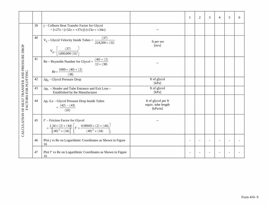
Form 410- 9
1 2 3 4 5 6
39 j – Colburn Heat Transfer Factor for Glycol = [ν27ο / (ν32ο × ν37ο)] (ν23ο × ν34ο)
--
40 Vg – Glycol Velocity Inside Tubes =
⟩⟨×⟩⟨
3150022437
,
⎥⎦
⎤⎢⎣
⎡⟩⟨
⟩⟨= 310000001
37Vg ,,
ft per sec
[m/s]
41 Re – Reynolds Number for Glycol =
⟩⟨×⟩⟨×⟩⟨
3812240
⟩⟨
⟩⟨×⟩⟨×=
382401000Re
--
42 Δpg – Glycol Pressure Drop
ft of glycol [kPa]
43 Δph – Header and Tube Entrance and Exit Loss – Established by the Manufacturer
ft of glycol [kPa]
44
Δpt /Le – Glycol Pressure Drop Inside Tubes
= ⟩⟨
⟩⟨−⟩⟨10
4342
ft of glycol per ft equiv. tube length
[kPa/m]
45
f’ – Friction Factor for Glycol
[ ] ⎥⎥⎦
⎤
⎢⎢⎣
⎡
⟩⟨×⟩⟨
⟩⟨×⟩⟨×=
⟩⟨×⟩⟨
⟩⟨×⟩⟨×=
3440442000450f
3440442341
22.'.
--
46
Plot j vs Re on Logarithmic Coordinates as Shown in Figure 16
-
-
-
-
-
-
CA
LCU
LATI
ON
OF
HEA
T TR
AN
SFER
AN
D P
RES
SUR
E D
RO
P F
AC
TOR
S FO
R P
LOTT
ING
-
-
-
-
- 47 Plot f’ vs Re on Logarithmic Coordinates as Shown in Figure
16
-
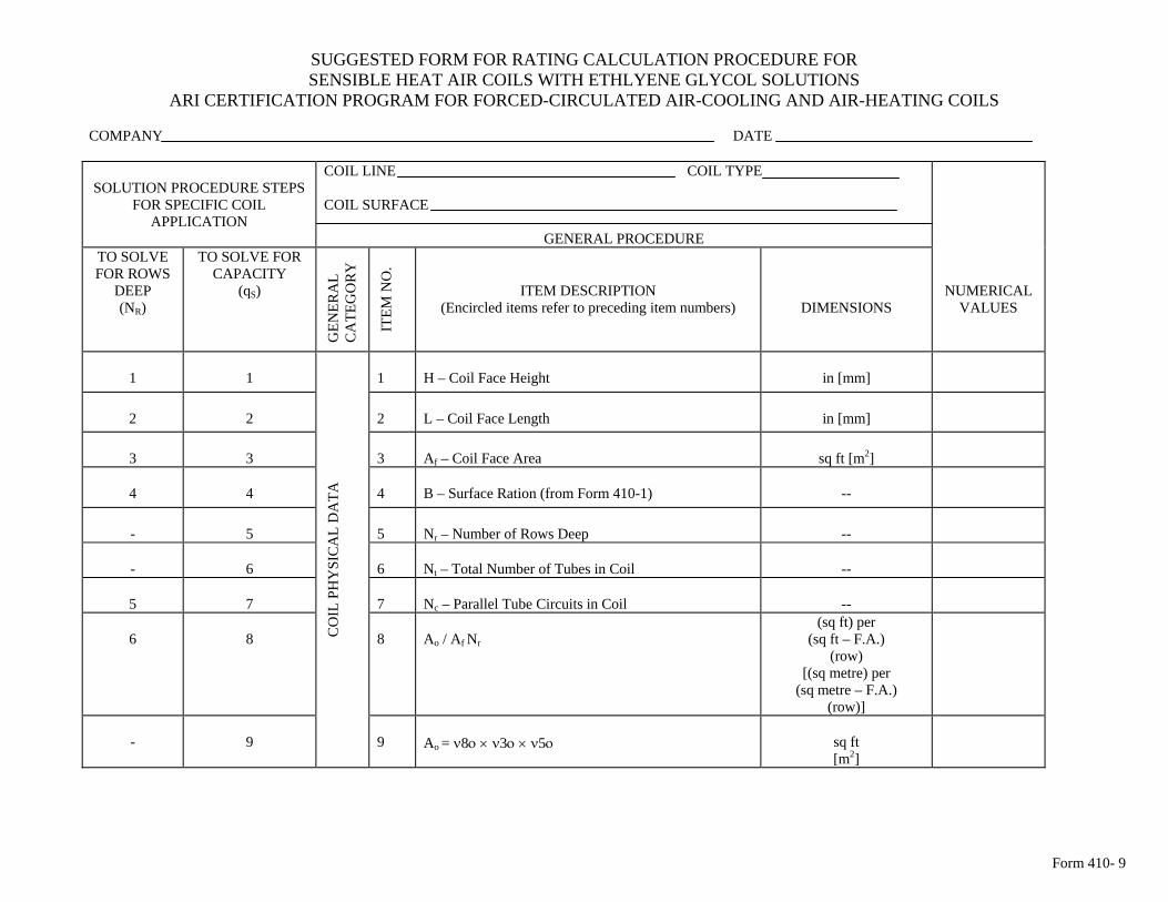
Form 410- 9
SUGGESTED FORM FOR RATING CALCULATION PROCEDURE FOR SENSIBLE HEAT AIR COILS WITH ETHLYENE GLYCOL SOLUTIONS
ARI CERTIFICATION PROGRAM FOR FORCED-CIRCULATED AIR-COOLING AND AIR-HEATING COILS
COMPANY DATE
SOLUTION PROCEDURE STEPS
FOR SPECIFIC COIL APPLICATION
COIL LINE COIL TYPE COIL SURFACE
GENERAL PROCEDURE
TO SOLVE FOR CAPACITY
(qS)
GEN
ERA
L C
ATE
GO
RY
ITEM
NO
.
ITEM DESCRIPTION (Encircled items refer to preceding item numbers)
TO SOLVE FOR ROWS
DEEP (NR)
DIMENSIONS
NUMERICAL VALUES
1
1
1
H – Coil Face Height
in [mm]
2
2
2
L – Coil Face Length
in [mm]
3
3
3
Af – Coil Face Area
sq ft [m2]
4
4
4
B – Surface Ration (from Form 410-1)
--
-
5
5
Nr – Number of Rows Deep
--
-
6
6
Nt – Total Number of Tubes in Coil
--
5
7
7
Nc – Parallel Tube Circuits in Coil
--
6
8
8
Ao / Af Nr
(sq ft) per (sq ft – F.A.)
(row) [(sq metre) per
(sq metre – F.A.) (row)]
CO
IL P
HY
SIC
AL
DA
TA
9
Ao = ν8ο × ν3ο × ν5ο
sq ft [m2]
-
9
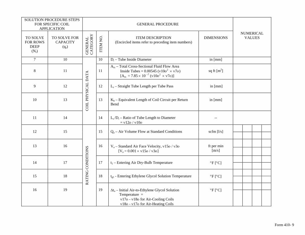
Form 410- 9
SOLUTION PROCEDURE STEPS
FOR SPECIFIC COIL APPLICATION
GENERAL PROCEDURE
TO SOLVE FOR ROWS
DEEP (Nr)
TO SOLVE FOR
CAPACITY (qs)
GEN
ERA
L C
ATE
GO
RY
ITEM
NO
. ITEM DESCRIPTION
(Encircled items refer to preceding item numbers)
DIMENSIONS
NUMERICAL VALUES
7 10 10 Di – Tube Inside Diameter in [mm]
8
11
11
Aix – Total Cross-Sectional Fluid Flow Area Inside Tubes = 0.00545 (ν10ο2 × ν7ο) [Aix = 7.85 × 10 –7 (ν10ο2 × ν7ο)]
sq ft [m2]
9
12
12
Ls – Straight Tube Length per Tube Pass
in [mm]
10
13
13
Kb – Equivalent Length of Coil Circuit per Return Bend
in [mm]
11
14
CO
IL P
HY
SIC
AL
DA
TA
14
Ls /Di – Ratio of Tube Length to Diameter = ν12ο / ν10ο
--
12
15
15
Qa – Air Volume Flow at Standard Conditions
scfm [l/s]
13
16
16
Va – Standard Air Face Velocity, ν15ο / ν3ο [Va = 0.001 × ν15ο / ν3ο]
ft per min
[m/s]
14
17
17
t1 – Entering Air Dry-Bulb Temperature
°F [°C]
15
18
18
tg1 - Entering Ethylene Glycol Solution Temperature
°F [°C]
16
19
RA
TIN
G C
ON
DIT
ION
S
19
Δto – Initial Air-to-Ethylene Glycol Solution Temperature = ν17ο - ν18ο for Air-Cooling Coils ν18ο - ν17ο for Air-Heating Coils
°F [°C]
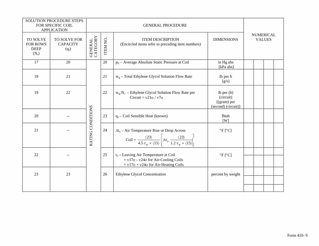
Form 410- 9
SOLUTION PROCEDURE STEPS
FOR SPECIFIC COIL APPLICATION
GENERAL PROCEDURE
TO SOLVE FOR ROWS
DEEP (Nr)
TO SOLVE FOR
CAPACITY (qs)
GEN
ERA
L C
ATE
GO
RY
ITEM
NO
. ITEM DESCRIPTION
(Encircled items refer to preceding item numbers)
DIMENSIONS
NUMERICAL VALUES
17 20 20 pS – Average Absolute Static Pressure at Coil in Hg abs [kPa abs]
18
21
21
wg – Total Ethylene Glycol Solution Flow Rate
lb per h
[g/s]
19
22
22
wg /Nc – Ethylene Glycol Solution Flow Rate per Circuit = ν21ο / ν7ο
lb per (h) (circuit)
[(gram) per (second) (circuit)]
20
--
23
qs – Coil Sensible Heat (known)
Btuh [W]
21
--
24
Δta – Air Temperature Rise or Drop Across
Coil = ⎥⎥⎦
⎤
⎢⎢⎣
⎡
⟩⟨×⟩⟨
Λ⟩⟨×
⟩⟨15c21
23t
15c5423
pa
p ..
°F [°C]
22
--
25
t2 – Leaving Air Temperature at Coil = ν17ο - ν24ο for Air-Cooling Coils = ν17ο + ν24ο for Air-Heating Coils
°F [°C]
23
23
RA
TIN
G C
ON
DIT
ION
S
26
Ethylene Glycol Concentration
percent by weight
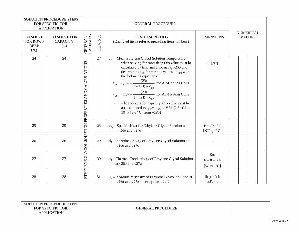
Form 410- 9
SOLUTION PROCEDURE STEPS
FOR SPECIFIC COIL APPLICATION
GENERAL PROCEDURE
TO SOLVE FOR ROWS
DEEP (Nr)
TO SOLVE FOR
CAPACITY (qs)
GEN
ERA
L C
ATE
GO
RY
ITEM
NO
. ITEM DESCRIPTION
(Encircled items refer to preceding item numbers)
DIMENSIONS
NUMERICAL VALUES
24 24 27 tgm – Mean Ethylene Glycol Solution Temperature - when solving for rows deep this value must be
calculated by trial and error using ν26ο and determining cpg for various values of tgm with the following equations:
pg
gm c2122318t
×⟩⟨×⟩⟨
+⟩⟨= for Air-Cooling Coils
pg
gm c2122318t
×⟩⟨×⟩⟨
+⟩⟨= for Air-Heating Coils
- when solving for capacity, this value must be approximated (suggest tgm be 5 °F [2.8 °C] to 10 °F [5.6 °C] from ν18ο)
°F [°C]
25
25
28
cpg – Specific Heat for Ethylene Glycol Solution at ν26ο and ν27ο
Btu /lb ⋅ °F [KJ/kg ⋅ °C]
26
26
29
dg – Specific Gravity of Ethylene Glycol Solution at ν26ο and ν27ο
--
27
27
30
kg – Thermal Conductivity of Ethylene Glycol Solution at ν26ο and ν27ο
FfthBtu
o−−
[W/m ⋅ °C]
ETH
YLE
NE
GLY
CO
L SO
LUTI
ON
PR
OPE
RTI
ES A
ND
CA
LCU
LATI
ON
S
31
28 28
μg – Absolute Viscosity of Ethylene Glycol Solution at ν26ο and ν27ο = centipoise × 2.42
lb per ft h [mPa ⋅ s]
SOLUTION PROCEDURE STEPS FOR SPECIFIC COIL
APPLICATION
GENERAL PROCEDURE
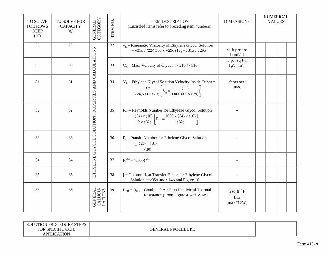
Form 410- 9
TO SOLVE FOR ROWS
DEEP (Nr)
TO SOLVE FOR
CAPACITY (qs)
GEN
ERA
L C
ATE
GO
RY
ITEM
NO
. ITEM DESCRIPTION
(Encircled items refer to preceding item numbers)
DIMENSIONS
NUMERICAL VALUES
29 29 32 νg – Kinematic Viscosity of Ethylene Glycol Solution = ν31ο / (224,500 × ν29ο) [νg = ν31ο / ν29ο]
sq ft per sec
[mm2/s]
30
30
33
Gg – Mass Velocity of Glycol = ν21ο / ν11ο
lb per sq ft h [g/s ⋅ m2]
31
31
34
Vg – Ethylene Glycol Solution Velocity Inside Tubes =
⎥⎦
⎤⎢⎣
⎡⟩⟨×
⟩⟨=
⟩⟨×⟩⟨
29000000133V
2950022433
g ,,,
ft per sec
[m/s]
32
32
35
Re – Reynolds Number for Ethylene Glycol Solution
= ⎥⎦
⎤⎢⎣
⎡⟩⟨
⟩⟨×⟩⟨×=
⟩⟨×⟩⟨×⟩⟨
3210341000R
32121034
e
--
33
33
36
Pr – Prandtl Number for Ethylene Glycol Solution
= ⟩⟨
⟩⟨×⟩⟨30
3128
--
34
34
37
Pr
2/3 = (ν36ο) 2/3
--
35
35 ET
HY
LEN
E G
LYC
OL
SOLU
TIO
N P
RO
PER
TIES
AN
D C
ALC
ULA
TIO
NS
38
j = Colburn Heat Transfer Factor for Ethylene Glycol Solution at ν35ο and ν14ο and Figure 16
--
36
36
GEN
ERA
L C
ALU
CU
-LA
TIO
NS
39
RaD + RmD – Combined Air Film Plus Metal Thermal Resistance (From Figure 4 with ν16ο)
BtuFftsqh o
[m2 ⋅ °C/W]
SOLUTION PROCEDURE STEPS FOR SPECIFIC COIL
APPLICATION
GENERAL PROCEDURE
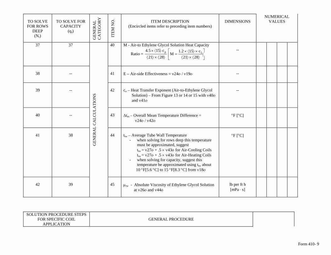
Form 410- 9
TO SOLVE FOR ROWS
DEEP (Nr)
TO SOLVE FOR
CAPACITY (qs)
GEN
ERA
L C
ATE
GO
RY
ITEM
NO
. ITEM DESCRIPTION
(Encircled items refer to preceding item numbers)
DIMENSIONS
NUMERICAL VALUES
37 37 40 M - Air-to Ethylene Glycol Solution Heat Capacity
Ratio = ⎥⎦
⎤⎢⎣
⎡⟩⟨×⟩⟨
×⟩⟨×=
⟩⟨×⟩⟨
⟩⟨×
2821c1521
M2821
c1554 1p ..
--
38
--
41
E – Air-side Effectiveness = ν24ο / ν19ο
--
39
--
42
co – Heat Transfer Exponent (Air-to-Ethylene Glycol Solution) – From Figure 13 or 14 or 15 with ν40ο and ν41ο
--
40
--
43
Δtm – Overall Mean Temperature Difference = ν24ο / ν42ο
°F [°C]
41
38
44
ttw – Average Tube Wall Temperature
- when solving for rows deep this temperature must be approximated, suggest ttw = ν27ο + .5 × ν43ο for Air-Cooling Coils ttw = ν27ο + .5 × ν43ο for Air-Heating Coils
- when solving for capacity, suggest this temperature be approximated using ttw about 10 °F[5.6 °C] to 15 °F[8.3 °C] from ν18ο
°F [°C]
GEN
ERA
L C
ALC
ULA
TIO
NS
45
42 39 μtw - Absolute Viscosity of Ethylene Glycol Solution
at ν26ο and ν44ο
lb per ft h [mPa ⋅ s]
SOLUTION PROCEDURE STEPS FOR SPECIFIC COIL
APPLICATION
GENERAL PROCEDURE
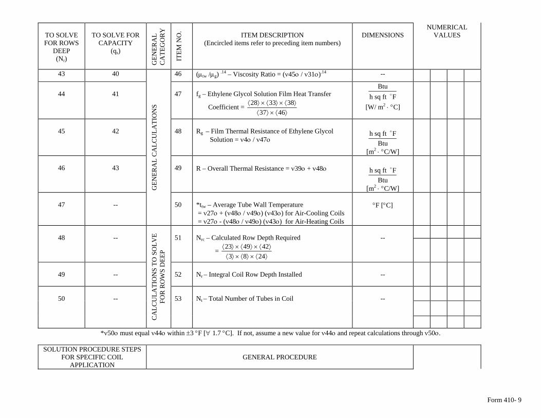
Form 410- 9
TO SOLVE FOR ROWS
DEEP (Nr)
TO SOLVE FOR
CAPACITY (qs)
GEN
ERA
L C
ATE
GO
RY
ITEM
NO
. ITEM DESCRIPTION
(Encircled items refer to preceding item numbers)
DIMENSIONS
NUMERICAL VALUES
43 40 46 (μtw /μg) .14 – Viscosity Ratio = (ν45ο / ν31ο).14 --
44
41
47
fg – Ethylene Glycol Solution Film Heat Transfer
Coefficient = ⟩⟨×⟩⟨
⟩⟨×⟩⟨×⟩⟨4637
383328 Fftsqh
Btuo
[W/ m2 ⋅ °C]
45
42
48
Rg – Film Thermal Resistance of Ethylene Glycol Solution = ν4ο / ν47ο
BtuFftsqh o
[m2 ⋅ °C/W]
46
43
49
R – Overall Thermal Resistance = ν39ο + ν48ο
BtuFftsqh o
[m2 ⋅ °C/W]
47
--
GEN
ERA
L C
ALC
ULA
TIO
NS
50
*ttw – Average Tube Wall Temperature = ν27ο + (ν48ο / ν49ο) (ν43ο) for Air-Cooling Coils = ν27ο - (ν48ο / ν49ο) (ν43ο) for Air-Heating Coils
°F [°C]
48
--
51
Nrc – Calculated Row Depth Required
= ⟩⟨×⟩⟨×⟩⟨⟩⟨×⟩⟨×⟩⟨
2483424923
--
49
--
52
Nr – Integral Coil Row Depth Installed
--
50
--
CA
LCU
LATI
ON
S TO
SO
LVE
FOR
RO
WS
DEE
P
53
Nt – Total Number of Tubes in Coil
--
*ν50ο must equal ν44ο within ±3 °F [∀ 1.7 °C]. If not, assume a new value for ν44ο and repeat calculations through ν50ο.
SOLUTION PROCEDURE STEPS FOR SPECIFIC COIL
APPLICATION
GENERAL PROCEDURE
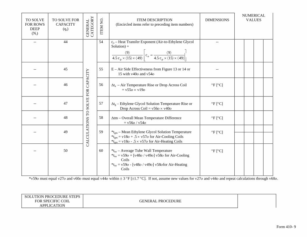
Form 410- 9
TO SOLVE FOR ROWS
DEEP (Nr)
TO SOLVE FOR
CAPACITY (qs)
GEN
ERA
L C
ATE
GO
RY
ITEM
NO
. ITEM DESCRIPTION
(Encircled items refer to preceding item numbers)
DIMENSIONS
NUMERICAL VALUES
-- 44 54 co – Heat Transfer Exponent (Air-to-Ethylene Glycol Solution) =
⎥⎥⎦
⎤
⎢⎢⎣
⎡
⟩⟨×⟩⟨×⟩⟨
=⟩⟨×⟩⟨×
⟩⟨4915c54
9c4915c54
9
po
p ..
--
--
45
55
E – Air Side Effectiveness from Figure 13 or 14 or 15 with ν40ο and ν54ο
--
--
46
56
Δta – Air Temperature Rise or Drop Across Coil = ν55ο × ν19ο
°F [°C]
--
47
57
Δtg – Ethylene Glycol Solution Temperature Rise or Drop Across Coil = ν56ο × ν40ο
°F [°C]
--
48
58
Δtm – Overall Mean Temperature Difference = ν56ο / ν54ο
°F [°C]
--
49
59
*tgm – Mean Ethylene Glycol Solution Temperature *tgm = ν18ο + .5 × ν57ο for Air-Cooling Coils *tgm = ν18ο - .5 × ν57ο for Air-Heating Coils
°F [°C]
CA
LCU
LATI
ON
S TO
SO
LVE
FOR
CA
PAC
ITY
60
*ttw – Average Tube Wall Temperature *ttw = ν59ο + [ν48ο / ν49ο] ν58ο for Air-Cooling
-- 50
Coils *ttw = ν59ο - [ν48ο / ν49ο] ν58οfor Air-Heating Coils
°F [°C]
*ν59ο must equal ν27ο and ν60ο must equal ν44ο within ± 3 °F [±1.7 °C]. If not, assume new values for ν27ο and ν44ο and repeat calculations through ν60ο.
SOLUTION PROCEDURE STEPS FOR SPECIFIC COIL
APPLICATION
GENERAL PROCEDURE
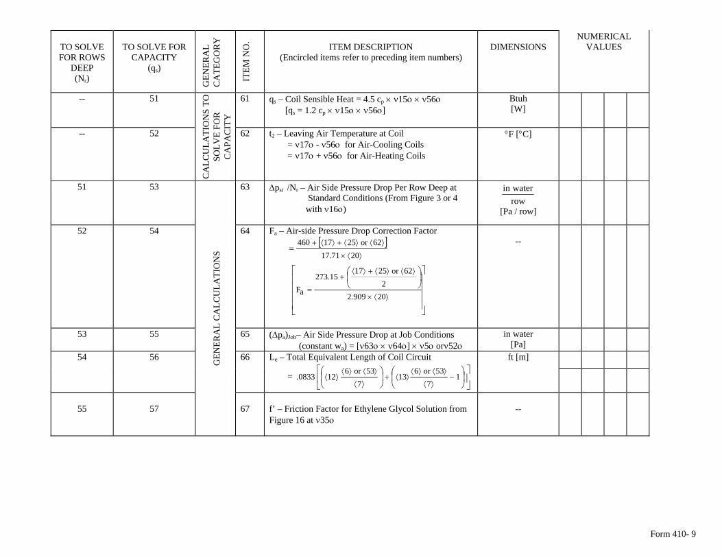
Form 410- 9
TO SOLVE FOR ROWS
DEEP (Nr)
TO SOLVE FOR
CAPACITY (qs)
GEN
ERA
L C
ATE
GO
RY
ITEM
NO
. ITEM DESCRIPTION
(Encircled items refer to preceding item numbers)
DIMENSIONS
NUMERICAL VALUES
-- 51 61 qs – Coil Sensible Heat = 4.5 cp × ν15ο × ν56ο [qs = 1.2 cp × ν15ο × ν56ο]
Btuh [W]
-- 52
CA
LCU
LATI
ON
S TO
SO
LVE
FOR
C
APA
CIT
Y
62 t2 – Leaving Air Temperature at Coil = ν17ο - ν56ο for Air-Cooling Coils = ν17ο + ν56ο for Air-Heating Coils
°F [°C]
51 53 63 Δpst /Nr – Air Side Pressure Drop Per Row Deep at Standard Conditions (From Figure 3 or 4 with ν16ο)
rowwaterin
[Pa / row]
52 54 64 Fa – Air-side Pressure Drop Correction Factor
[ ]
⎥⎥⎥⎥
⎦
⎤
⎢⎢⎢⎢
⎣
⎡⎟⎠⎞
⎜⎝⎛
=
⟩⟨×
⟩⟨⟩⟨+⟩⟨+
=
⟩⟨×
⟩⟨⟩⟨+⟩⟨+
2090922
62or251715273
aF
20711762or2517460
.
.
.
--
53 55 65 (Δpa)Job– Air Side Pressure Drop at Job Conditions (constant wa) = [ν63ο × ν64ο] × ν5ο orν52ο
in water [Pa]
54 56
G
ENER
AL
CA
LCU
LATI
ON
S
66 Le – Total Equivalent Length of Coil Circuit
= ⎥⎦
⎤⎢⎣
⎡⎟⎠
⎞⎜⎝
⎛⎟⎠
⎞⎜⎝
⎛−
⟩⟨
⟩⟨⟩⟨⟩⟨+
⟩⟨
⟩⟨⟩⟨⟩⟨ 1
753or6
137
53or6120833.
ft [m]
55
57
67
f’ – Friction Factor for Ethylene Glycol Solution from Figure 16 at ν35ο
--
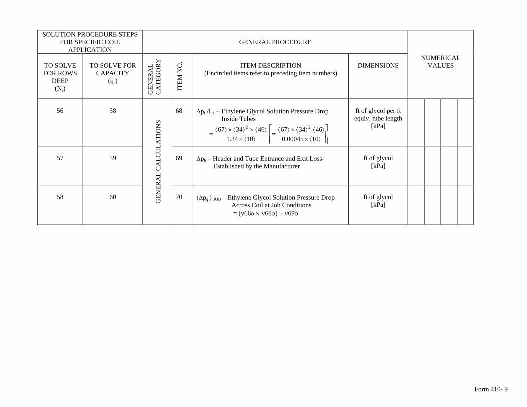
Form 410- 9
SOLUTION PROCEDURE STEPS
FOR SPECIFIC COIL APPLICATION
GENERAL PROCEDURE
TO SOLVE FOR ROWS
DEEP (Nr)
TO SOLVE FOR
CAPACITY (qs)
GEN
ERA
L C
ATE
GO
RY
ITEM
NO
. ITEM DESCRIPTION
(Encircled items refer to preceding item numbers)
DIMENSIONS
NUMERICAL VALUES
56
58
68
Δpt /Le – Ethylene Glycol Solution Pressure Drop Inside Tubes
⎥⎥⎦
⎤
⎢⎢⎣
⎡
⟩⟨×⟩⟨⟩⟨×⟩⟨
=⟩⟨×
⟩⟨×⟩⟨×⟩⟨=
10000450463467
10341463467 22
..
ft of glycol per ft equiv. tube length
[kPa]
57
59
69
Δph – Header and Tube Entrance and Exit Loss- Established by the Manufacturer
ft of glycol
[kPa]
G
ENER
AL
CA
LCU
LATI
ON
S
(Δpg ) JOB – Ethylene Glycol Solution Pressure Drop Across Coil at Job Conditions = (ν66ο × ν68ο) + ν69ο
ft of glycol
[kPa] 58 60 70
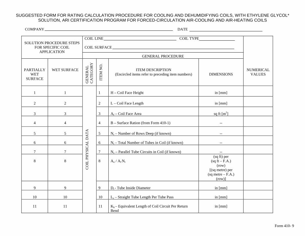
Form 410- 9
SUGGESTED FORM FOR RATING CALCULATION PROCEDURE FOR COOLING AND DEHUMIDIFYING COILS, WITH ETHYLENE GLYCOL* SOLUTION, ARI CERTIFICATION PROGRAM FOR FORCED-CIRCULATION AIR-COOLING AND AIR-HEATING COILS
COMPANY DATE
SOLUTION PROCEDURE STEPS
FOR SPECIFIC COIL APPLICATION
COIL LINE COIL TYPE COIL SURFACE
GENERAL PROCEDURE
WET SURFACE
GEN
ERA
L C
ATE
GO
RY
ITEM
NO
.
ITEM DESCRIPTION (Encircled items refer to preceding item numbers)
PARTIALLY WET
SURFACE DIMENSIONS
NUMERICAL VALUES
1
1
1
H – Coil Face Height
in [mm]
2
2
2
L – Coil Face Length
in [mm]
3
3
3
Af – Coil Face Area
sq ft [m2]
4
4
4
B – Surface Ration (from Form 410-1)
--
5
5
5
Nr – Number of Rows Deep (if known)
--
6
6
6
Nt – Total Number of Tubes in Coil (if known)
--
7
7
7
Nc – Parallel Tube Circuits in Coil (if known)
--
8
8
8
Ao / Af Nr
(sq ft) per (sq ft – F.A.)
(row) [(sq metre) per
(sq metre – F.A.) (row)]
9
9
9
Di - Tube Inside Diameter
in [mm]
10
10
Ls – Straight Tube Length Per Tube Pass
in [mm]
10
11
11
CO
IL P
HY
SIC
AL
DA
TA
11
Kb – Equivalent Length of Coil Circuit Per Return Bend
in [mm]
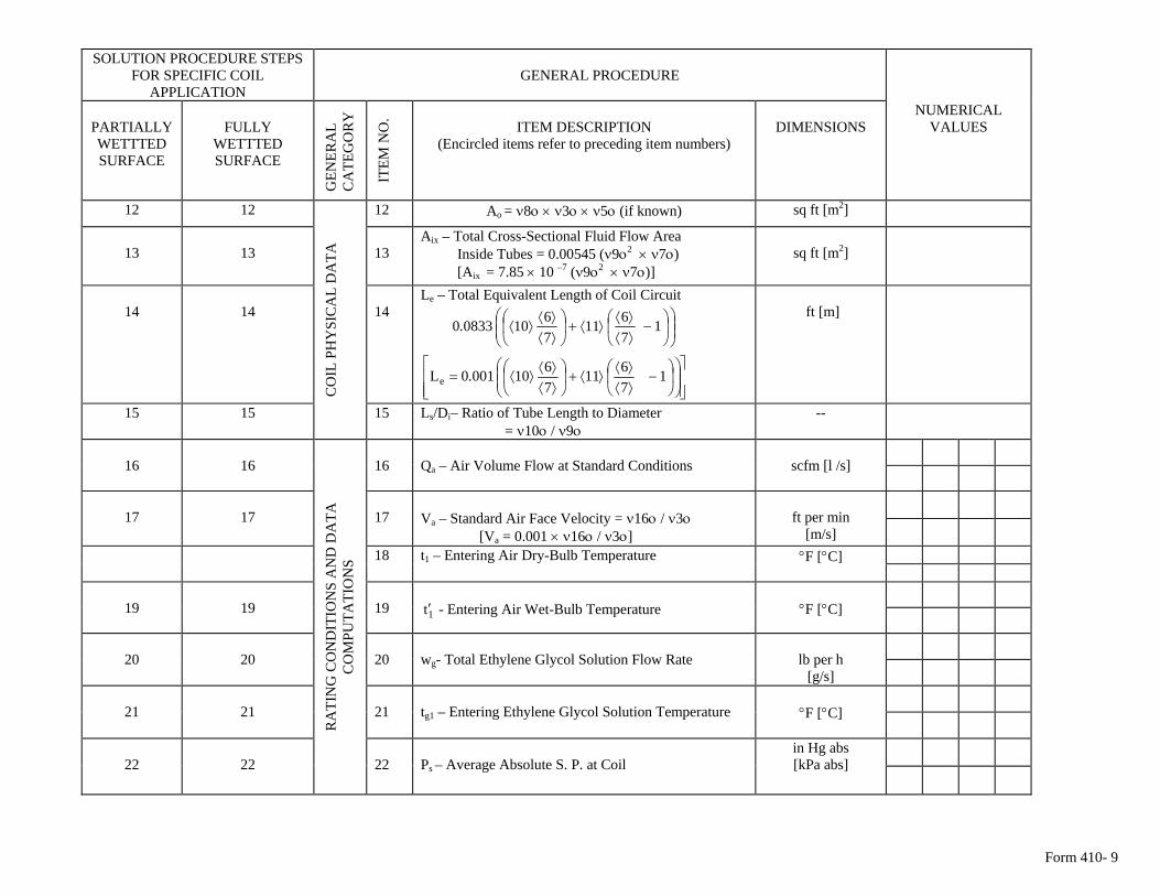
Form 410- 9
SOLUTION PROCEDURE STEPS FOR SPECIFIC COIL
APPLICATION
GENERAL PROCEDURE
PARTIALLY WETTTED SURFACE
FULLY
WETTTED SURFACE
GEN
ERA
L C
ATE
GO
RY
ITEM
NO
. ITEM DESCRIPTION
(Encircled items refer to preceding item numbers)
DIMENSIONS
NUMERICAL VALUES
12 12 12 Ao = ν8ο × ν3ο × ν5ο (if known) sq ft [m2]
13
13
13
Aix – Total Cross-Sectional Fluid Flow Area Inside Tubes = 0.00545 (ν9ο2 × ν7ο) [Aix = 7.85 × 10 –7 (ν9ο2 × ν7ο)]
sq ft [m2]
14
14
14
Le – Total Equivalent Length of Coil Circuit
⎟⎟⎠
⎞⎜⎜⎝
⎛⎟⎠
⎞⎜⎝
⎛−
⟩⟨⟩⟨
⟩⟨+⎟⎠
⎞⎜⎝
⎛⟩⟨⟩⟨
⟩⟨ 17611
761008330.
⎥⎥⎦
⎤
⎢⎢⎣
⎡⎟⎟⎠
⎞⎜⎜⎝
⎛⎟⎠
⎞⎜⎝
⎛−
⟩⟨⟩⟨
⟩⟨+⎟⎠
⎞⎜⎝
⎛⟩⟨⟩⟨
⟩⟨= 17611
76100010Le .
ft [m]
15 15
CO
IL P
HY
SIC
AL
DA
TA
15 Ls/Di– Ratio of Tube Length to Diameter = ν10ο / ν9ο
--
16
16
16
scfm [l /s]
Qa – Air Volume Flow at Standard Conditions
17
17
17
Va – Standard Air Face Velocity = ν16ο / ν3ο [Va = 0.001 × ν16ο / ν3ο]
ft per min
[m/s]
18 t1 – Entering Air Dry-Bulb Temperature °F [°C]
19
19
19
1t′ - Entering Air Wet-Bulb Temperature
°F [°C]
20
20
20
wg- Total Ethylene Glycol Solution Flow Rate
lb per h
[g/s]
21
21
21
tg1 – Entering Ethylene Glycol Solution Temperature
°F [°C]
22
22
RA
TIN
G C
ON
DIT
ION
S A
ND
DA
TA
CO
MPU
TATI
ON
S
22
in Hg abs Ps – Average Absolute S. P. at Coil [kPa abs]
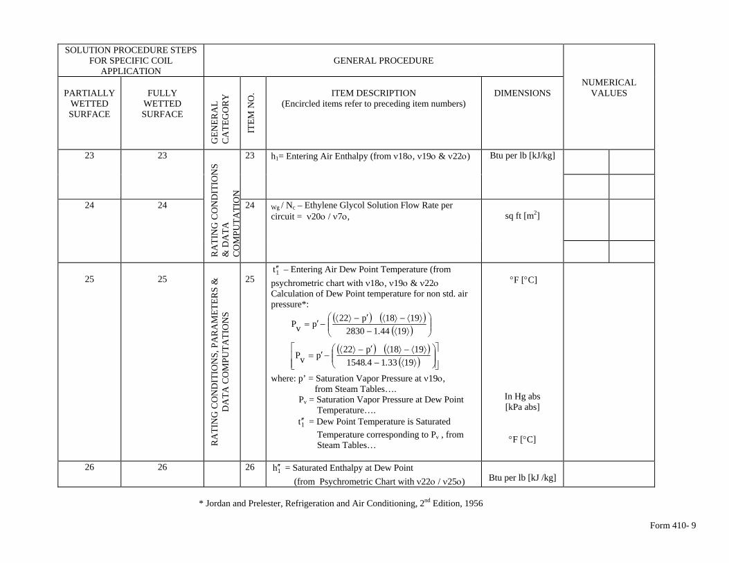
Form 410- 9
SOLUTION PROCEDURE STEPS FOR SPECIFIC COIL
APPLICATION
GENERAL PROCEDURE
PARTIALLY
WETTED SURFACE
FULLY
WETTED SURFACE
GEN
ERA
L C
ATE
GO
RY
ITEM
NO
.
ITEM DESCRIPTION
(Encircled items refer to preceding item numbers)
DIMENSIONS
NUMERICAL VALUES
23 23 23 h1= Entering Air Enthalpy (from ν18ο, ν19ο & ν22ο) Btu per lb [kJ/kg]
24 24 R
ATI
NG
CO
ND
ITIO
NS
&
DA
TA
CO
MPU
TATI
ON
24 Wg / Nc – Ethylene Glycol Solution Flow Rate per circuit = ν20ο / ν7ο,
sq ft [m2]
25
25
RA
TIN
G C
ON
DIT
ION
S, P
AR
AM
ETER
S &
D
ATA
CO
MPU
TATI
ON
S
25
1t ′′ – Entering Air Dew Point Temperature (from psychrometric chart with ν18ο, ν19ο & ν22ο Calculation of Dew Point temperature for non std. air pressure*:
( ) ( )( ) ⎟⎟
⎠
⎞⎜⎜⎝
⎛⟩⟨−
⟩⟨−⟩⟨′−⟩⟨−′=
1944128301918p22pvP
.
( ) ( )
( ) ⎥⎥⎦
⎤
⎢⎢⎣
⎡⎟⎟⎠
⎞⎜⎜⎝
⎛⟩⟨−⟩⟨−⟩⟨′−⟩⟨
−′=1933141548
1918p22pvP..
where: p’ = Saturation Vapor Pressure at ν19ο, from Steam Tables…. Pv = Saturation Vapor Pressure at Dew Point Temperature…. 1t ′′ = Dew Point Temperature is Saturated Temperature corresponding to Pv , from Steam Tables…
°F [°C]
In Hg abs [kPa abs]
°F [°C]
26 26 26 1h ′′ = Saturated Enthalpy at Dew Point (from Psychrometric Chart with ν22ο / ν25ο)
Btu per lb [kJ /kg]
* Jordan and Prelester, Refrigeration and Air Conditioning, 2nd Edition, 1956
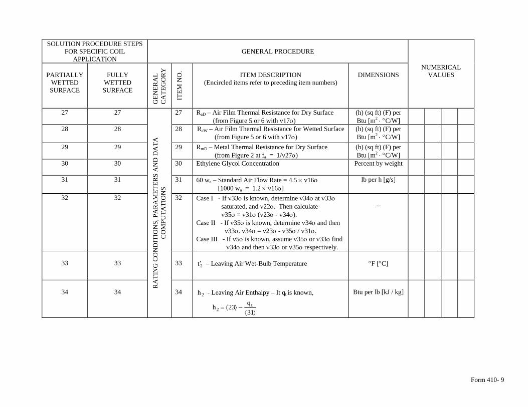
Form 410- 9
SOLUTION PROCEDURE STEPS
FOR SPECIFIC COIL APPLICATION
GENERAL PROCEDURE
PARTIALLY
WETTED SURFACE
FULLY
WETTED SURFACE
GEN
ERA
L C
ATE
GO
RY
ITEM
NO
. ITEM DESCRIPTION
(Encircled items refer to preceding item numbers)
DIMENSIONS
NUMERICAL VALUES
27 27 27 RaD – Air Film Thermal Resistance for Dry Surface (from Figure 5 or 6 with ν17ο)
(h) (sq ft) (F) per Btu [m2 ⋅ °C/W]
28 28 28 RaW – Air Film Thermal Resistance for Wetted Surface (from Figure 5 or 6 with ν17ο)
(h) (sq ft) (F) per Btu [m2 ⋅ °C/W]
29 29 29 RmD – Metal Thermal Resistance for Dry Surface (from Figure 2 at fa = 1/ν27ο)
(h) (sq ft) (F) per Btu [m2 ⋅ °C/W]
30 30 30 Ethylene Glycol Concentration Percent by weight
31 31 31 60 wa – Standard Air Flow Rate = 4.5 × ν16ο [1000 wa = 1.2 × ν16ο]
lb per h [g/s]
32 32 32 Case I - If ν33ο is known, determine ν34ο at ν33ο saturated, and ν22ο. Then calculate ν35ο = ν31ο (ν23ο - ν34ο). Case II - If ν35ο is known, determine ν34ο and then ν33ο. ν34ο = ν23ο - ν35ο / ν31ο. Case III - If ν5ο is known, assume ν35ο or ν33ο find ν34ο and then ν33ο or ν35ο respectively.
--
33
33
33
2t ′ – Leaving Air Wet-Bulb Temperature
°F [°C]
RA
TIN
G C
ON
DIT
ION
S, P
AR
AM
ETER
S A
ND
DA
TA
CO
MPU
TATI
ON
S
34
34 34
2h - Leaving Air Enthalpy – It qt is known,
⟩⟨
−⟩⟨=31q
23h t2
Btu per lb [kJ / kg]
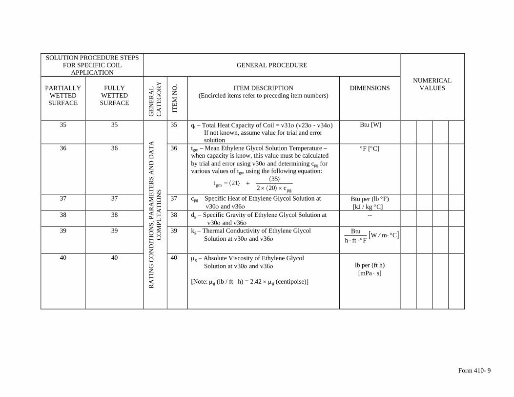
Form 410- 9
SOLUTION PROCEDURE STEPS FOR SPECIFIC COIL
APPLICATION
GENERAL PROCEDURE
PARTIALLY
WETTED SURFACE
FULLY
WETTED SURFACE
GEN
ERA
L C
ATE
GO
RY
ITEM
NO
. ITEM DESCRIPTION
(Encircled items refer to preceding item numbers)
DIMENSIONS
NUMERICAL VALUES
35 35 35 qt – Total Heat Capacity of Coil = ν31ο (ν23ο - ν34ο) If not known, assume value for trial and error solution
Btu [W]
36 36 36 tgm – Mean Ethylene Glycol Solution Temperature – when capacity is know, this value must be calculated by trial and error using ν30ο and determining cpg for various values of tgm using the following equation:
pg
gm c2023521t
×⟩⟨×⟩⟨
+⟩⟨=
°F [°C]
37 37 37 cpg – Specific Heat of Ethylene Glycol Solution at ν30ο and ν36ο
Btu per (lb °F) [kJ / kg °C]
38 38 38 dg – Specific Gravity of Ethylene Glycol Solution at ν30ο and ν36ο
--
39 39 39 kg – Thermal Conductivity of Ethylene Glycol Solution at ν30ο and ν36ο [ ]CmW
FfthBtu
°⋅°⋅⋅
/
40 40
RA
TIN
G C
ON
DIT
ION
S, P
AR
AM
ETER
S A
ND
DA
TA
CO
MPU
TATI
ON
S
40 μg – Absolute Viscosity of Ethylene Glycol Solution at ν30ο and ν36ο [Note: μg (lb / ft ⋅ h) = 2.42 × μg (centipoise)]
lb per (ft h)
[mPa ⋅ s]
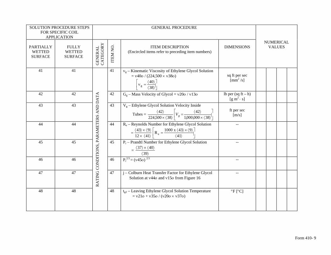
Form 410- 9
SOLUTION PROCEDURE STEPS
FOR SPECIFIC COIL APPLICATION
GENERAL PROCEDURE
PARTIALLY
WETTED SURFACE
FULLY
WETTED SURFACE
GEN
ERA
L C
ATE
GO
RY
ITEM
NO
. ITEM DESCRIPTION
(Encircled items refer to preceding item numbers)
DIMENSIONS
NUMERICAL VALUES
41 41 41 νg – Kinematic Viscosity of Ethylene Glycol Solution = ν40ο / (224,500 × ν38ο)
⎥⎦
⎤⎢⎣
⎡⟩⟨⟩⟨
=ν3840
g
sq ft per sec
[mm2 /s]
42 42 42 Gg – Mass Velocity of Glycol = ν20ο / ν13ο lb per (sq ft – h) [g m2 ⋅ s]
43 43 43 Vg – Ethylene Glycol Solution Velocity Inside
Tubes = ⎥⎦
⎤⎢⎣
⎡⟩⟨×
⟩⟨=
⟩⟨×⟩⟨
38000000142
3850022442
,,V
, g
ft per sec
[m/s]
44 44 44 Re – Reynolds Number for Ethylene Glycol Solution
⎥⎦
⎤⎢⎣
⎡⟩⟨
⟩⟨×⟩⟨=
⟩⟨×⟩⟨×⟩⟨
=41
943x1000R4112
943e
--
45 45 45 Pr – Prandtl Number for Ethylene Glycol Solution
= ⟩⟨
⟩⟨×⟩⟨39
4037
--
46 46 46 Pr2/3 = (ν45ο) 2/3 --
47 47 47 j – Colburn Heat Transfer Factor for Ethylene Glycol Solution at ν44ο and ν15ο from Figure 16
--
RA
TIN
G C
ON
DIT
ION
S, P
AR
AM
ETER
S A
ND
DA
TA
48 48 48 tg2 – Leaving Ethylene Glycol Solution Temperature = ν21ο + ν35ο / (ν20ο × ν37ο)
°F [°C]
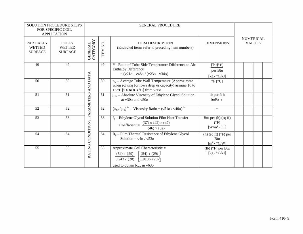
Form 410- 9
SOLUTION PROCEDURE STEPS
FOR SPECIFIC COIL APPLICATION
GENERAL PROCEDURE
PARTIALLY
WETTED SURFACE
FULLY
WETTED SURFACE
GEN
ERA
L C
ATE
GO
RY
ITEM
NO
. ITEM DESCRIPTION
(Encircled items refer to preceding item numbers)
DIMENSIONS
NUMERICAL VALUES
49 49 49 Y –Ratio of Tube-Side Temperature Difference to Air Enthalpy Difference = (ν21ο - ν48ο / (ν23ο - ν34ο)
( ) ( )Btuper
Flb °
[kg ⋅ °C/kJ]
50 50 50 ttw – Average Tube Wall Temperature (Approximate when solving for rows deep or capacity) assume 10 to 15 °F [5.6 to 8.3 °C] from ν36ο
°F [°C]
51 51 51 μtw – Absolute Viscosity of Ethylene Glycol Solution at ν30ο and ν50ο
lb per ft h [mPa ⋅s]
52 52 52 (μtw / μg).14 – Viscosity Ratio = (ν51ο / ν40ο).14 --
53 53 53 fg – Ethylene Glycol Solution Film Heat Transfer
Coefficient = ⟩⟨×⟩⟨
⟩⟨×⟩⟨×⟩⟨5246
474237
Btu per (h) (sq ft) (°F)
[W/m2 ⋅ °C]
54 54 54 Rg – Film Thermal Resistance of Ethylene Glycol Solution = ν4ο / ν53ο
(h) (sq ft) (°F) per Btu
[m2 ⋅ °C/W]
55 55
RA
TIN
G C
ON
DIT
ION
S, P
AR
AM
ETER
S A
ND
DA
TA
55 Approximate Coil Characteristic =
⎥⎦
⎤⎢⎣
⎡⟩⟨×⟩⟨+⟩⟨
⟩⟨×⟩⟨+⟩⟨
2801812954
2824302954
..
used to obtain Rmw in ν63ο
(lb) (°F) per Btu [kg ⋅ °C/kJ]
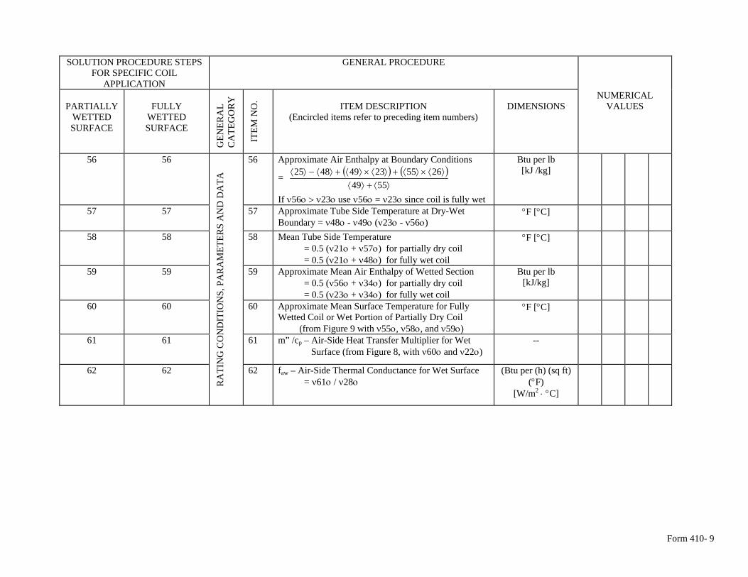
Form 410- 9
SOLUTION PROCEDURE STEPS
FOR SPECIFIC COIL APPLICATION
GENERAL PROCEDURE
PARTIALLY
WETTED SURFACE
FULLY
WETTED SURFACE
GEN
ERA
L C
ATE
GO
RY
ITEM
NO
. ITEM DESCRIPTION
(Encircled items refer to preceding item numbers)
DIMENSIONS
NUMERICAL VALUES
56 56 56 Approximate Air Enthalpy at Boundary Conditions ( ) ( )
⟩⟨+⟩⟨⟩⟨×⟩⟨+⟩⟨×⟩⟨+⟩⟨−⟩⟨
5549265523494825 =
If ν56ο > ν23ο use ν56ο = ν23ο since coil is fully wet
Btu per lb [kJ /kg]
57 57 57 Approximate Tube Side Temperature at Dry-Wet Boundary = ν48ο - ν49ο (ν23ο - ν56ο)
°F [°C]
58 58 58 Mean Tube Side Temperature = 0.5 (ν21ο + ν57ο) for partially dry coil = 0.5 (ν21ο + ν48ο) for fully wet coil
°F [°C]
59 59 59 Approximate Mean Air Enthalpy of Wetted Section = 0.5 (ν56ο + ν34ο) for partially dry coil = 0.5 (ν23ο + ν34ο) for fully wet coil
Btu per lb [kJ/kg]
60 60 60 Approximate Mean Surface Temperature for Fully Wetted Coil or Wet Portion of Partially Dry Coil (from Figure 9 with ν55ο, ν58ο, and ν59ο)
°F [°C]
61 61 61 m” /cp – Air-Side Heat Transfer Multiplier for Wet Surface (from Figure 8, with ν60ο and ν22ο)
--
62 62
RA
TIN
G C
ON
DIT
ION
S, P
AR
AM
ETER
S A
ND
DA
TA
62 faw – Air-Side Thermal Conductance for Wet Surface = ν61ο / ν28ο
(Btu per (h) (sq ft) (°F)
[W/m2 ⋅ °C]
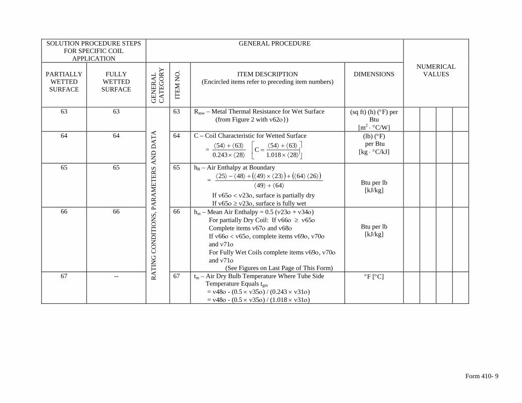
Form 410- 9
SOLUTION PROCEDURE STEPS
FOR SPECIFIC COIL APPLICATION
GENERAL PROCEDURE
PARTIALLY
WETTED SURFACE
FULLY
WETTED SURFACE
GEN
ERA
L C
ATE
GO
RY
ITEM
NO
. ITEM DESCRIPTION
(Encircled items refer to preceding item numbers)
DIMENSIONS
NUMERICAL VALUES
63 63 63 Rmw – Metal Thermal Resistance for Wet Surface (from Figure 2 with ν62ο})
(sq ft) (h) (°F) per Btu
[m2 ⋅ °C/W]
64 64 64 C – Coil Characteristic for Wetted Surface
= ⎥⎦
⎤⎢⎣
⎡⟩⟨×⟩⟨+⟩⟨
=⟩⟨×⟩⟨+⟩⟨
2801816354C
2824306354
..
(lb) (°F) per Btu
[kg ⋅ °C/kJ]
65 65 65 hB – Air Enthalpy at Boundary
= ( ) ( )⟩⟨+⟩⟨
⟩⟨⟩⟨+⟩⟨×⟩⟨+⟩⟨−⟩⟨6449
266423494825
If ν65ο < ν23ο, surface is partially dry If ν65ο ≥ ν23ο, surface is fully wet
Btu per lb [kJ/kg]
66 66 66 hm – Mean Air Enthalpy = 0.5 (ν23ο + ν34ο) For partially Dry Coil: If ν66ο ≥ ν65ο Complete items ν67ο and ν68ο If ν66ο < ν65ο, complete items ν69ο, ν70ο and ν71ο For Fully Wet Coils complete items ν69ο, ν70ο and ν71ο (See Figures on Last Page of This Form)
Btu per lb [kJ/kg]
67 -- RA
TIN
G C
ON
DIT
ION
S, P
AR
AM
ETER
S A
ND
DA
TA
67 tm – Air Dry Bulb Temperature Where Tube Side Temperature Equals tgm
= ν48ο - (0.5 × ν35ο) / (0.243 × ν31ο) = ν48ο - (0.5 × ν35ο) / (1.018 × ν31ο)
°F [°C]
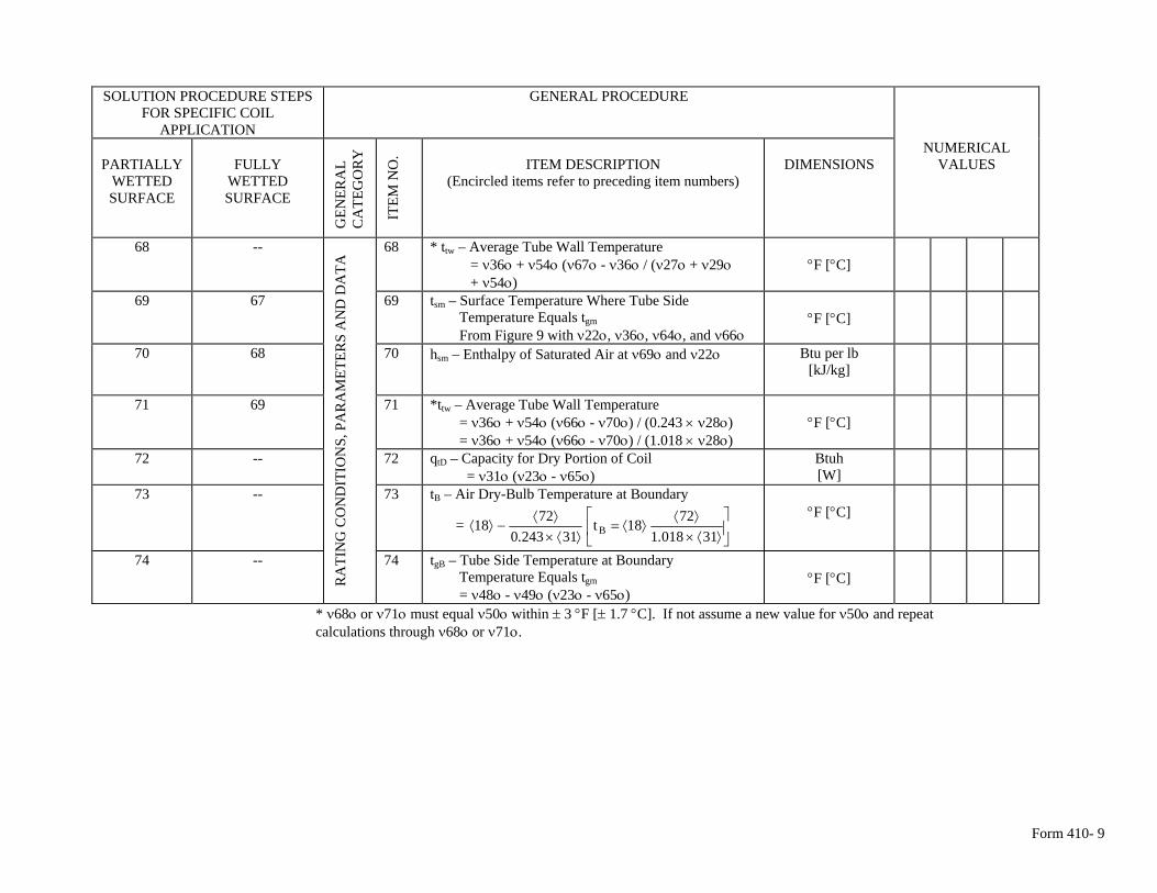
Form 410- 9
SOLUTION PROCEDURE STEPS
FOR SPECIFIC COIL APPLICATION
GENERAL PROCEDURE
PARTIALLY
WETTED SURFACE
FULLY
WETTED SURFACE
GEN
ERA
L C
ATE
GO
RY
ITEM
NO
. ITEM DESCRIPTION
(Encircled items refer to preceding item numbers)
DIMENSIONS
NUMERICAL VALUES
68 -- 68 * ttw – Average Tube Wall Temperature = ν36ο + ν54ο (ν67ο - ν36ο / (ν27ο + ν29ο + ν54ο)
°F [°C]
69 67 69 tsm – Surface Temperature Where Tube Side Temperature Equals tgm
From Figure 9 with ν22ο, ν36ο, ν64ο, and ν66ο
°F [°C]
70 68 70 hsm – Enthalpy of Saturated Air at ν69ο and ν22ο Btu per lb [kJ/kg]
71 69 71 *ttw – Average Tube Wall Temperature = ν36ο + ν54ο (ν66ο - ν70ο) / (0.243 × ν28ο) = ν36ο + ν54ο (ν66ο - ν70ο) / (1.018 × ν28ο)
°F [°C]
72 -- 72 qtD – Capacity for Dry Portion of Coil = ν31ο (ν23ο - ν65ο)
Btuh [W]
73 -- 73 tB – Air Dry-Bulb Temperature at Boundary
= ⎥⎦
⎤⎢⎣
⎡⟩⟨×
⟩⟨⟩⟨=
⟩⟨×⟩⟨
−⟩⟨310181
7218t312430
7218 B ..
°F [°C]
74 --
RA
TIN
G C
ON
DIT
ION
S, P
AR
AM
ETER
S A
ND
DA
TA
74 tgB – Tube Side Temperature at Boundary Temperature Equals tgm
= ν48ο - ν49ο (ν23ο - ν65ο)
°F [°C]
* ν68ο or ν71ο must equal ν50ο within ± 3 °F [± 1.7 °C]. If not assume a new value for ν50ο and repeat calculations through ν68ο or ν71ο.
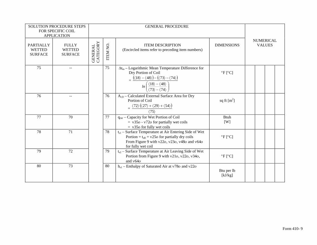
Form 410- 9
SOLUTION PROCEDURE STEPS
FOR SPECIFIC COIL APPLICATION
GENERAL PROCEDURE
PARTIALLY
WETTED SURFACE
FULLY
WETTED SURFACE
GEN
ERA
L C
ATE
GO
RY
ITEM
NO
. ITEM DESCRIPTION
(Encircled items refer to preceding item numbers)
DIMENSIONS
NUMERICAL VALUES
75 -- 75 Δtm – Logarithmic Mean Temperature Difference for Dry Portion of Coil
= ( ) ( )
⎟⎟⎠
⎞⎜⎜⎝
⎛⟩⟨−⟩⟨⟩⟨−⟩⟨
⟩⟨−⟩⟨−⟩⟨−⟩⟨
74734818
74734818
ln
°F [°C]
76 -- 76 AcD – Calculated External Surface Area for Dry Portion of Coil
= ( )
⟩⟨⟩⟨+⟩⟨+⟩⟨⟩⟨
7554292772
sq ft [m2]
77 70 77 qtW – Capacity for Wet Portion of Coil = ν35ο - ν72ο for partially wet coils = ν35ο for fully wet coils
Btuh [W]
78 71 78 ts1 – Surface Temperature at Air Entering Side of Wet Portion = tsB = ν25ο for partially dry coils From Figure 9 with ν22ο, ν23ο, ν48ο and ν64ο for fully wet coil
°F [°C]
79 72 79 ts2 – Surface Temperature at Air Leaving Side of Wet Portion from Figure 9 with ν21ο, ν22ο, ν34ο, and ν64ο
°F [°C]
80 73 80 hs1 – Enthalpy of Saturated Air at ν78ο and ν22ο
Btu per lb
[kJ/kg]
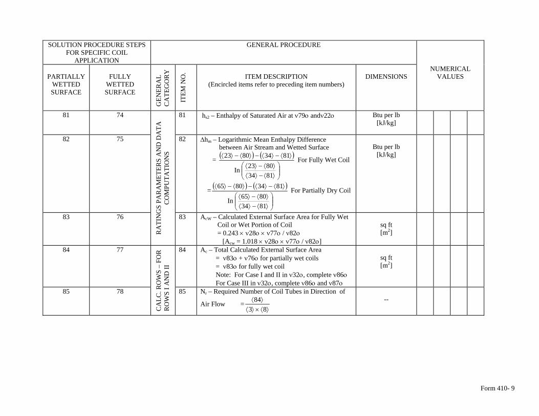
Form 410- 9
SOLUTION PROCEDURE STEPS
FOR SPECIFIC COIL APPLICATION
GENERAL PROCEDURE
PARTIALLY
WETTED SURFACE
FULLY
WETTED SURFACE
GEN
ERA
L C
ATE
GO
RY
ITEM
NO
. ITEM DESCRIPTION
(Encircled items refer to preceding item numbers)
DIMENSIONS
NUMERICAL VALUES
81 74 81 hs2 – Enthalpy of Saturated Air at ν79ο andν22ο Btu per lb [kJ/kg]
82 75 82 Δhm – Logarithmic Mean Enthalpy Difference between Air Stream and Wetted Surface
= ( ) ( )
⎟⎟⎠
⎞⎜⎜⎝
⎛⟩⟨−⟩⟨⟩⟨−⟩⟨
⟩⟨−⟩⟨−⟩⟨−⟩⟨
81348023In
81348023 For Fully Wet Coil
= ( ) ( )
⎟⎟⎠
⎞⎜⎜⎝
⎛⟩⟨−⟩⟨⟩⟨−⟩⟨
⟩⟨−⟩⟨−⟩⟨−⟩⟨
81348065In
81348065 For Partially Dry Coil
Btu per lb
[kJ/kg]
83 76
RA
TIN
GS
PAR
AM
ETER
S A
ND
DA
TA
CO
MPU
TATI
ON
S
83 AcW – Calculated External Surface Area for Fully Wet Coil or Wet Portion of Coil = 0.243 × ν28ο × ν77ο / ν82ο [Acw = 1.018 × ν28ο × ν77ο / ν82ο]
sq ft [m2]
84 77 84 Ac – Total Calculated External Surface Area = ν83ο + ν76ο for partially wet coils = ν83ο for fully wet coil Note: For Case I and II in ν32ο, complete ν86ο For Case III in ν32ο, complete ν86ο and ν87ο
sq ft [m2]
85 78
CA
LC. R
OW
S –
FOR
R
OW
S I A
ND
II
85 Nr – Required Number of Coil Tubes in Direction of
Air Flow =⟩⟨×⟩⟨
⟩⟨83
84
--
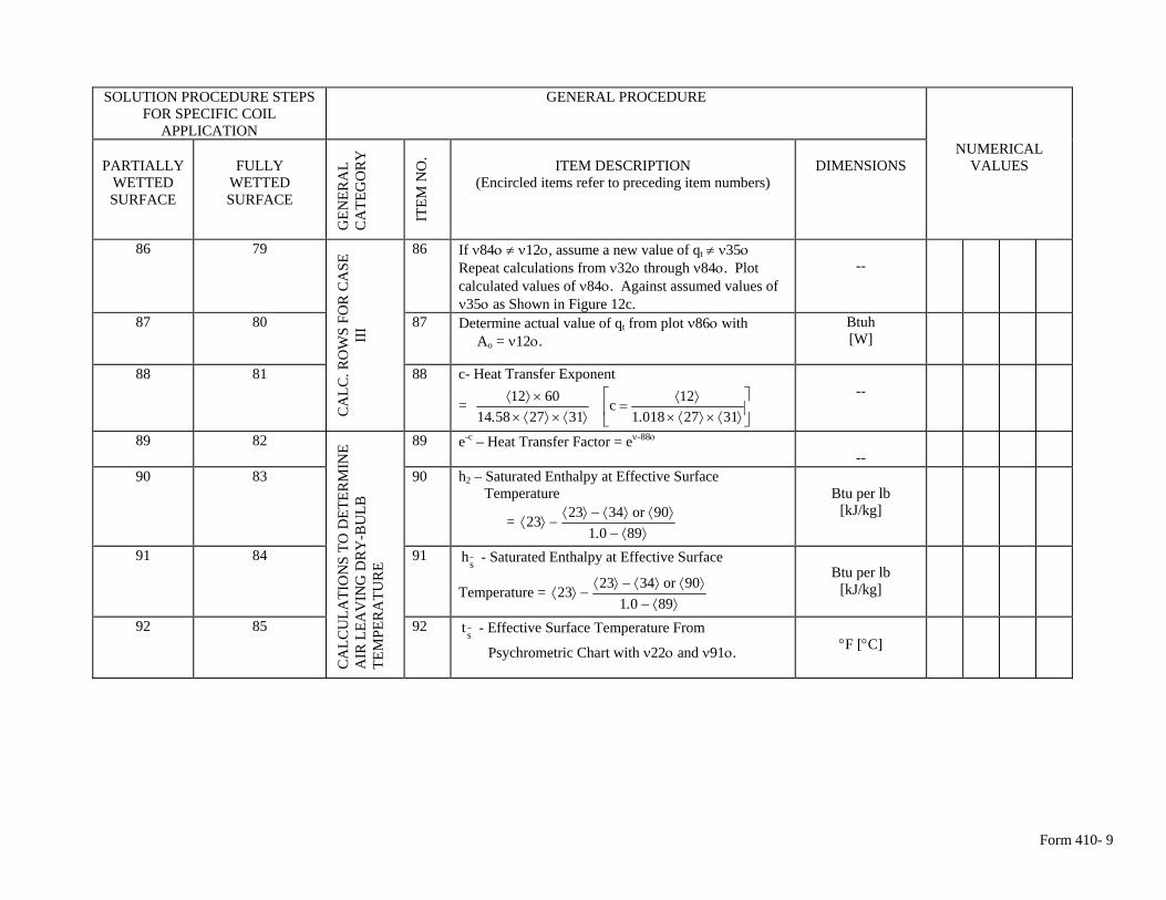
Form 410- 9
SOLUTION PROCEDURE STEPS
FOR SPECIFIC COIL APPLICATION
GENERAL PROCEDURE
PARTIALLY
WETTED SURFACE
FULLY
WETTED SURFACE
GEN
ERA
L C
ATE
GO
RY
ITEM
NO
. ITEM DESCRIPTION
(Encircled items refer to preceding item numbers)
DIMENSIONS
NUMERICAL VALUES
86 79 86 If ν84ο ≠ ν12ο, assume a new value of qt ≠ ν35ο Repeat calculations from ν32ο through ν84ο. Plot calculated values of ν84ο. Against assumed values of ν35ο as Shown in Figure 12c.
--
87 80 87 Determine actual value of qt from plot ν86ο with Ao = ν12ο.
Btuh [W]
88 81
CA
LC. R
OW
S FO
R C
ASE
II
I 88 c- Heat Transfer Exponent
= ⎥⎦
⎤⎢⎣
⎡⟩⟨×⟩⟨×
⟩⟨=
⟩⟨×⟩⟨××⟩⟨
3127018112c
312758146012
..
--
89 82 89 e-c – Heat Transfer Factor = eν-88ο --
90 83 90 h2 – Saturated Enthalpy at Effective Surface Temperature
= ⟩⟨−
⟩⟨⟩⟨−⟩⟨−⟩⟨
890190or342323
.
Btu per lb
[kJ/kg]
91 84 91 sh - Saturated Enthalpy at Effective Surface
Temperature = ⟩⟨−
⟩⟨⟩⟨−⟩⟨−⟩⟨
890190or342323
.
Btu per lb
[kJ/kg]
92 85
CA
LCU
LATI
ON
S TO
DET
ERM
INE
AIR
LEA
VIN
G D
RY
-BU
LB
TEM
PER
ATU
RE
92 st - Effective Surface Temperature From
Psychrometric Chart with ν22ο and ν91ο.
°F [°C]
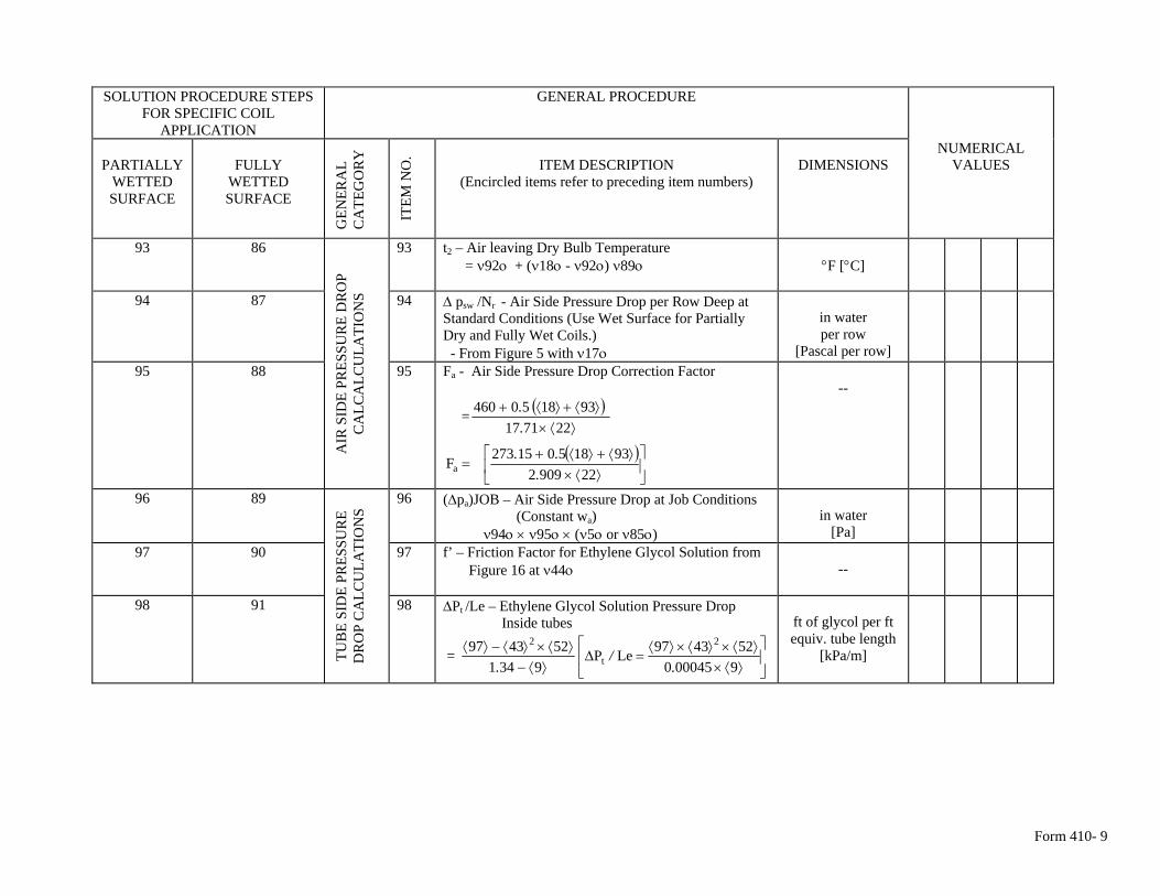
Form 410- 9
SOLUTION PROCEDURE STEPS
FOR SPECIFIC COIL APPLICATION
GENERAL PROCEDURE
PARTIALLY
WETTED SURFACE
FULLY
WETTED SURFACE
GEN
ERA
L C
ATE
GO
RY
ITEM
NO
. ITEM DESCRIPTION
(Encircled items refer to preceding item numbers)
DIMENSIONS
NUMERICAL VALUES
93 86 93 t2 – Air leaving Dry Bulb Temperature = ν92ο + (ν18ο - ν92ο) ν89ο
°F [°C]
94 87 94 Δ psw /Nr - Air Side Pressure Drop per Row Deep at Standard Conditions (Use Wet Surface for Partially Dry and Fully Wet Coils.) - From Figure 5 with ν17ο
in water per row
[Pascal per row]
95 88
AIR
SID
E PR
ESSU
RE
DR
OP
CA
LCA
LCU
LATI
ON
S 95 Fa - Air Side Pressure Drop Correction Factor
= ( )⟩⟨×
⟩⟨+⟩⟨+227117
931850460..
( )⎥⎦
⎤⎢⎣
⎡⟩⟨×
⟩⟨+⟩⟨+=
22909293185015273Fa .
..
--
96 89 96 (Δpa)JOB – Air Side Pressure Drop at Job Conditions (Constant wa) ν94ο × ν95ο × (ν5ο or ν85ο)
in water
[Pa]
97 90 97 f’ – Friction Factor for Ethylene Glycol Solution from Figure 16 at ν44ο
--
98 91
TUB
E SI
DE
PRES
SUR
E D
RO
P C
ALC
ULA
TIO
NS
98 ΔPt /Le – Ethylene Glycol Solution Pressure Drop Inside tubes
= ⎥⎦
⎤⎢⎣
⎡
⟩⟨×⟩⟨×⟩⟨×⟩⟨
=Δ⟩⟨−
⟩⟨×⟩⟨−⟩⟨9000450
524397LeP9341
524397 2
t
2
./
.
ft of glycol per ft equiv. tube length
[kPa/m]
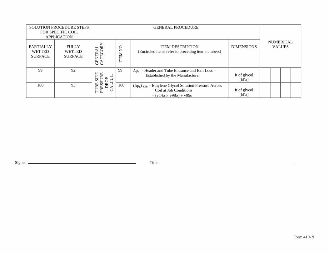
Form 410- 9
SOLUTION PROCEDURE STEPS
FOR SPECIFIC COIL APPLICATION
GENERAL PROCEDURE
PARTIALLY
WETTED SURFACE
FULLY
WETTED SURFACE
GEN
ERA
L C
ATE
GO
RY
ITEM
NO
. ITEM DESCRIPTION
(Encircled items refer to preceding item numbers)
DIMENSIONS
NUMERICAL VALUES
99 92 99 Δph - Header and Tube Entrance and Exit Loss – Established by the Manufacturer
ft of glycol
[kPa]
100 93
TUB
E SI
DE
PRES
SUR
E D
RO
P C
ALC
UL.
100 (Δpg) JOB – Ethylene Glycol Solution Pressure Across ft of glycol Coil at Job Conditions
[kPa] = (ν14ο × ν98ο) + ν99ο Signed Title
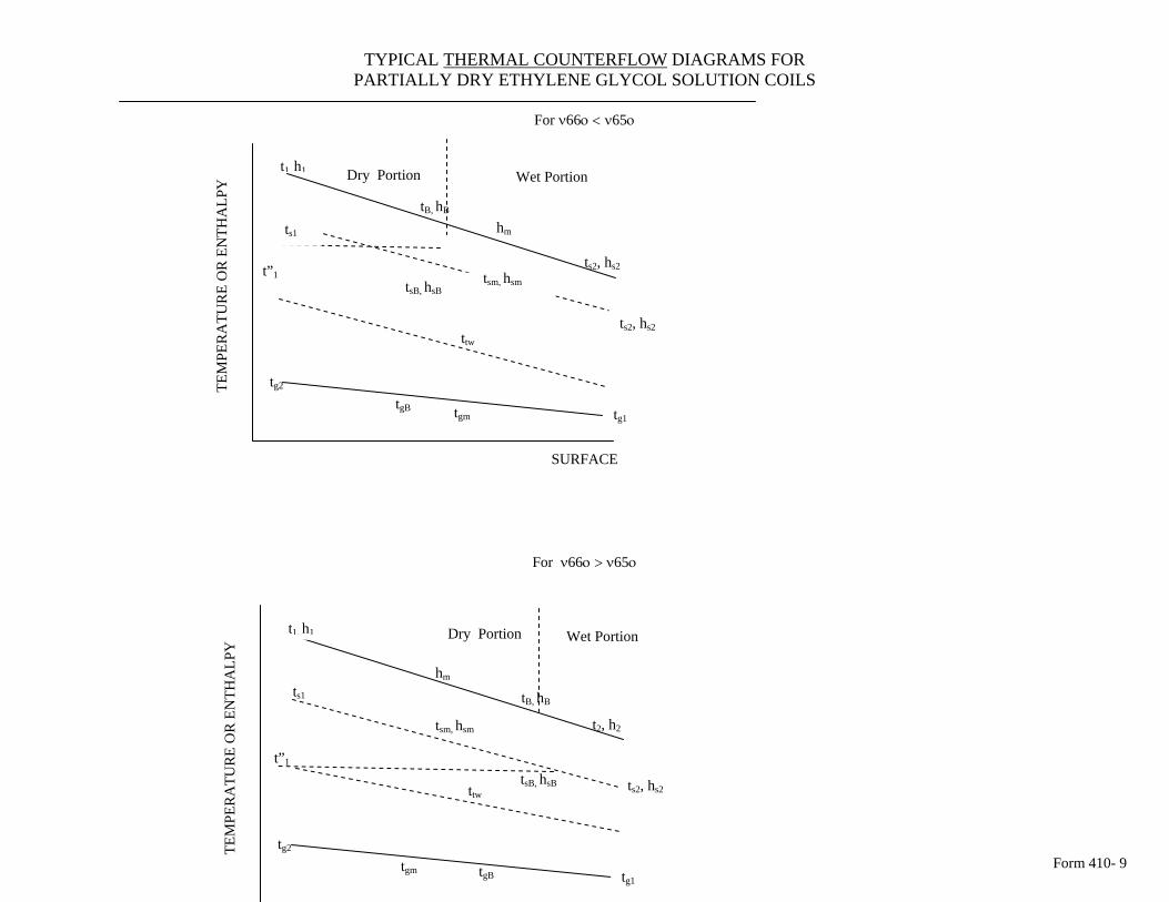
Form 410- 9
TYPICAL THERMAL COUNTERFLOW DIAGRAMS FOR PARTIALLY DRY ETHYLENE GLYCOL SOLUTION COILS
For ν66ο < ν65ο
SURFACE
For ν66ο > ν65ο
tg1
t1, h1
tsm, hsmt”1
ts2, hs2
ts1
tsB, hsB
tgm
tg2
tgB
ttw
ts2, hs2
hm
tB, hB
Wet PortionDry Portion
TEM
PER
ATU
RE
OR
EN
THA
LPY
tgm
tg2
tgB
tsB, hsB
t”1
ttwts2, hs2
t2, h2
hm
tB, hB
t h Dry Portion1, 1 Wet Portion
TEM
PER
ATU
RE
OR
EN
THA
LPY
ts1
tsm, hsm
tg1

Form 410- 9
SURFACE
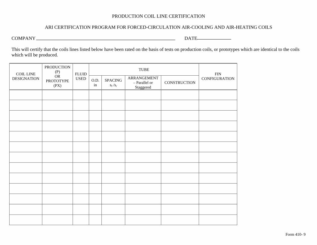
Form 410- 9
PRODUCTION COIL LINE CERTIFICATION
ARI CERTIFICATION PROGRAM FOR FORCED-CIRCULATION AIR-COOLING AND AIR-HEATING COILS
COMPANY DATE This will certify that the coils lines listed below have been rated on the basis of tests on production coils, or prototypes which are identical to the coils which will be produced.
TUBE COIL LINE
DESIGNATION
PRODUCTION (P) OR
PROTOTYPE (PX)
FLUID USED O.D.
in SPACING
sf /sr
ARRANGEMENT – Parallel or Staggered
CONSTRUCTION
FIN CONFIGURATION
Form 410- 9
Signed Title