FOR VISION FUNCTION - Motoman...Vision Funciton iv 169274-1CD HW1482636. WARNING • Before...
80
MANUAL NO. 0 HW1482636 Part Number: 169274-1CD Revision: 0 FS100 OPTIONS INSTRUCTIONS FOR VISION FUNCTION Upon receipt of the product and prior to initial operation, read these instructions thoroughly and retain for future reference. MOTOMAN INSTRUCTIONS MOTOMAN- INSTRUCTIONS FS100 INSTRUCTIONS FS100 OPERATOR’S MANUAL FS100 MAINTENANCE MANUAL 1/80
Transcript of FOR VISION FUNCTION - Motoman...Vision Funciton iv 169274-1CD HW1482636. WARNING • Before...

MANUAL NO.
0HW1482636
Part Number: 169274-1CDRevision: 0
FS100 OPTIONSINSTRUCTIONSFOR VISION FUNCTION
Upon receipt of the product and prior to initial operation, read these instructions thoroughly and retain for future reference.
MOTOMAN INSTRUCTIONSMOTOMAN- INSTRUCTIONSFS100 INSTRUCTIONSFS100 OPERATOR’S MANUALFS100 MAINTENANCE MANUAL
1/80

ii
169274-1CD
HW1482636
Vision Funciton
MANDATORY• This manual explains the vision function of the FS100. Read this
manual carefully and be sure to understand its contents before handling the FS100.
• General items related to safety are listed in Chapter 1: Safety of the FS100 INSTRUCTIONS. To ensure correct and safe operation, carefully read the FS100 Instructions before reading this manual.
CAUTION• Some drawings in this manual are shown with the protective covers
or shields removed for clarity. Be sure all covers and shields are replaced before operating this product.
• The drawings and photos in this manual are representative examples and differences may exist between them and the delivered product.
• YASKAWA may modify this model without notice when necessary due to product improvements, modifications, or changes in specifications. If such modification is made, the manual number will also be revised.
• If your copy of the manual is damaged or lost, contact a YASKAWA representative to order a new copy. The representatives are listed on the back cover. Be sure to tell the representative the manual number listed on the front cover.
• YASKAWA is not responsible for incidents arising from unauthorized modification of its products. Unauthorized modification voids your product’s warranty.
2/80

iii
169274-1CD
HW1482636
Vision Funciton
Notes for Safe OperationRead this manual carefully before installation, operation, maintenance, or inspection of the FS100.
In this manual, the Notes for Safe Operation are classified as “WARNING”, “CAUTION”, “MANDATORY”, or ”PROHIBITED”.
Even items described as “CAUTION” may result in a serious accident in some situations. At any rate, be sure to follow these important items
WARNINGIndicates a potentially hazardous situation which, if not avoided, could result in death or serious injury to personnel.
CAUTIONIndicates a potentially hazardous situation which, if not avoided, could result in minor or moderate injury to personnel and damage to equipment. It may also be used to alert against unsafe practices.
MANDATORYAlways be sure to follow explicitly the items listed under this heading.
PROHIBITEDMust never be performed.
NOTETo ensure safe and efficient operation at all times, be sure to follow all instructions, even if not designated as “CAUTION” and “WARNING”.
3/80

iv
169274-1CD
HW1482636
Vision Funciton
.
WARNING• Before operating the manipulator, check that servo power is turned
OFF pressing the emergency stop buttons on the front door of the FS100 and the programming pendant.When the servo power is turned OFF, the SERVO ON LED on the programming pendant is turned OFF.
Injury or damage to machinery may result if the emergency stop circuit cannot stop the manipulator during an emergency. The manipulator should not be used if the emergency stop buttons do not function.
Figure 1: Emergency Stop Button
• Once the emergency stop button is released, clear the cell of all items which could interfere with the operation of the manipulator.Then turn the servo power ON.
Injury may result from unintentional or unexpected manipulator motion.
Figure 2: Release of Emergency Stop
TURN
• Observe the following precautions when performing teaching operations within the P-point maximum envelope of the manipulator:
– View the manipulator from the front whenever possible.
– Always follow the predetermined operating procedure.
– Keep in mind the emergency response measures against the manipulator’s unexpected motion toward you.
– Ensure that you have a safe place to retreat in case of emergency.
Improper or unintended manipulator operation may result in injury.
• Confirm that no person is present in the P-point maximum envelope of the manipulator and that you are in a safe location before:
– Turning ON the power for the FS100.
– Moving the manipulator with the programming pendant.
– Running the system in the check mode.
– Performing automatic operations.
Injury may result if anyone enters the P-point maximum envelope of the manipulator during operation. Always press an emergency stop button immediately if there is a problem.
The emergency stop buttons are located on the right of front door of the FS100 and the programming pendant.
4/80

v
169274-1CD
HW1482636
Vision Funciton
Definition of Terms Used Often in This ManualThe MOTOMAN is the YASKAWA industrial robot product.
The MOTOMAN usually consists of the manipulator, the controller, the programming pendant, and supply cables.
In this manual, the equipment is designated as follows:
CAUTION• Perform the following inspection procedures prior to conducting
manipulator teaching. If problems are found, repair them immediately, and be sure that all other necessary processing has been performed.
– Check for problems in manipulator movement.
– Check for damage to insulation and sheathing of external wires.
• Always return the programming pendant to the hook on the FS100 cabinet after use.
The programming pendant can be damaged if it is left in the P-point maximum envelope of the manipulator, on the floor, or near fixtures.
• Read and understand the Explanation of Warning Labels in the FS100 Instructions before operating the manipulator.
Equipment Manual Designation
FS100 Controller FS100
FS100 Programming Pendant Programming Pendant
Cable between the manipulator and FS100 Manipulator Cable
5/80
vi
169274-1CD
HW1482636
Vision Funciton
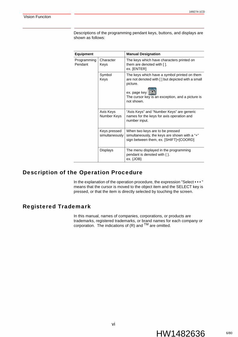
Descriptions of the programming pendant keys, buttons, and displays are shown as follows:
Description of the Operation ProcedureIn the explanation of the operation procedure, the expression "Select • • • " means that the cursor is moved to the object item and the SELECT key is pressed, or that the item is directly selected by touching the screen.
Registered TrademarkIn this manual, names of companies, corporations, or products are trademarks, registered trademarks, or brand names for each company or corporation. The indications of (R) and TM are omitted.
Equipment Manual Designation
ProgrammingPendant
Character Keys
The keys which have characters printed on them are denoted with [ ].ex. [ENTER]
SymbolKeys
The keys which have a symbol printed on them are not denoted with [ ] but depicted with a small picture.
ex. page key The cursor key is an exception, and a picture is not shown.
Axis KeysNumber Keys
“Axis Keys” and “Number Keys” are generic names for the keys for axis operation and number input.
Keys pressed simultaneously
When two keys are to be pressed simultaneously, the keys are shown with a “+” sign between them, ex. [SHIFT]+[COORD]
Displays The menu displayed in the programming pendant is denoted with { }.ex. {JOB}
6/80

vii
169274-1CD
HW1482636
Vision Funciton Table of Contents
Table of Contents
1 Outline ............................................................................................................................................ 1-1
2 Communications Settings ............................................................................................................... 2-1
2.1 Connecting the Vision System to the FS100 ..................................................................... 2-1
2.1.1 List of Connectable Vision Systems ..................................................................... 2-1
2.1.2 System Configuration ........................................................................................... 2-1
2.2 Vision System Settings...................................................................................................... 2-2
2.2.1 OMRON FZ Serial Communication (Ethernet) ..................................................... 2-22.2.1.1 System Settings ...................................................................................... 2-22.2.1.2 Detection Scene Settings........................................................................ 2-52.2.1.3 Settings During Operation ....................................................................... 2-7
2.2.2 COGNEX In-Sight Telnet (Ethernet)..................................................................... 2-82.2.2.1 VisionView Settings................................................................................. 2-92.2.2.2 System Settings .................................................................................... 2-112.2.2.3 Camera Job Specifications.................................................................... 2-142.2.2.4 Object Type Settings............................................................................. 2-16
2.2.3 KEYENCE CV Serial Communication (Ethernet) ............................................... 2-192.2.3.1 System Settings .................................................................................... 2-202.2.3.2 Object Type Settings............................................................................. 2-21
2.2.4 KEYENCE XG Serial Communication (Ethernet) ............................................... 2-242.2.4.1 System Settings .................................................................................... 2-252.2.4.2 Setting the Inspection Test Number ...................................................... 2-26
2.2.5 SHARP IV-S200 Serial Communication (Ethernet) ............................................ 2-302.2.5.1 System Settings .................................................................................... 2-312.2.5.2 Setting the Object Type Setting Number............................................... 2-32
2.3 Vision Condition File Settings.......................................................................................... 2-39
2.4 Setting Parameters and Variables ................................................................................... 2-40
2.4.1 Setting Parameters............................................................................................. 2-40
2.4.2 Setting Variables ................................................................................................ 2-41
3 Detection Job Creation and Execution............................................................................................ 3-1
3.1 Job for Detection Result Storage....................................................................................... 3-1
3.2 Job for Part Type Changing............................................................................................... 3-2
7/80

Table of Contents
viii
169274-1CD
HW1482636
Vision Funciton
4 List of Robot Language (INFORM III) Commands ..........................................................................4-1
4.1 OMRON FZ Serial Communication (Ethernet)...................................................................4-2
4.1.1 Usage Example ....................................................................................................4-2
4.2 COGNEX In-Sight Telnet (Ethernet) .................................................................................. 4-4
4.2.1 Usage example.....................................................................................................4-4
4.3 KEYENCE CV Serial Communication (Ethernet)............................................................... 4-8
4.3.1 Usage example.....................................................................................................4-8
4.4 KEYENCE XG Serial Communication (Ethernet) ............................................................4-10
4.4.1 Usage example...................................................................................................4-10
4.5 SHARP IV-S200 Serial Communication (Ethernet) .........................................................4-12
4.5.1 Usage example...................................................................................................4-12
5 Miscellaneous Functions.................................................................................................................5-1
5.1 Vision Condition Files ........................................................................................................5-1
5.2 Calibration File ................................................................................................................... 5-2
5.3 Loading and Saving Vision Files........................................................................................5-3
5.3.1 Saving Files ..........................................................................................................5-3
5.3.2 Saving Files ..........................................................................................................5-4
5.4 Alarm B Variable Output Function .....................................................................................5-5
5.4.1 Setting Procedure.................................................................................................5-7
5.5 Communication Retry Function..........................................................................................5-8
5.5.1 Setting Procedure.................................................................................................5-9
5.6 Vision System IP Address Modification .............................................................................5-9
5.6.1 Setting Procedure...............................................................................................5-10
5.7 Changing the Ethernet Communication Port Number of the Vision Device.....................5-10
5.7.1 Setting Procedure...............................................................................................5-10
6 Alarm List ........................................................................................................................................6-1
7 Parameter List.................................................................................................................................7-1
8 Revision History ..............................................................................................................................8-1
8/80

1-1
169274-1CD
HW1482636
Vision Funciton 1 Outline
1 Outline
The vision function communicates with the image processing device (vision system) to control the robot according to image processing results.
The vision function operation procedures are as follows.
9/80

2 Communications Settings2.1 Connecting the Vision System to the FS100
2-1
169274-1CD
HW1482636
Vision Funciton
2 Communications Settings
2.1 Connecting the Vision System to the FS100
2.1.1 List of Connectable Vision Systems
The connectable vision systems to use with the vision function are as follows.
2.1.2 System Configuration
An example of the system configuration that performs communication for the vision function is shown below. For the machine configuration of each vision system, refer to the system's documentation.
(1) For serial communication/Telnet (Ethernet)
(2) For serial communication (Ethernet) via a switching hub
Maker Model Communication method
Note
OMRON FZ2 seriesFZ3 seriesFZ4 series
Ethernet
COGNEX In-Sight seriesIn-Sight Micro series
Ethernet • Yaskawa's proprietary camera job is used
• The EasyBuilder function is not supported
KEYENCE CV-5000/3000 series Ethernet
XG-7000 series Ethernet
SHARP IV-S200 series Ethernet
10/80

2-2
169274-1CD
HW1482636
Vision Funciton 2 Communications Settings2.2 Vision System Settings
2.2 Vision System Settings
Perform vision system settings so that communication can occur between the FS100 and the vision system. Perform the settings according to the communication specification as follows. After setting, follow the vision system's operation manual to save the settings, and then use them.
2.2.1 OMRON FZ Serial Communication (Ethernet)
An example of the basic system configuration for Omron FZ serial communication (Ethernet) for the FS100 vision function is shown below.
2.2.1.1 System Settings
Perform settings on the vision system only after returning its settings to the default factory values.
1. On the adjustment window, select {System} → {Controller} → {Startup setting}.
No. Required device No. of items
Omron FZ series 1
FZ-compatible camera 1 to 4
FS100 1
24V power supply unit 1
FZ camera cable (regular/flex-resistant) 1 to 4
Ethernet cable (cross) (for Ethernet connections) 1
11/80

2 Communications Settings2.2 Vision System Settings
2-3
169274-1CD
HW1482636
Vision Funciton
2. Select the {Communication} tab, and change {Serial (Ethernet)} to “Normal (TCP)”, and then click {OK}.
3. "Setting is applied after save data and reboot." is displayed. Click {OK}.
4. On the adjustment window, click {Data save}, and then click {Yes}.
12/80
2-4
169274-1CD
HW1482636
Vision Funciton 2 Communications Settings2.2 Vision System Settings
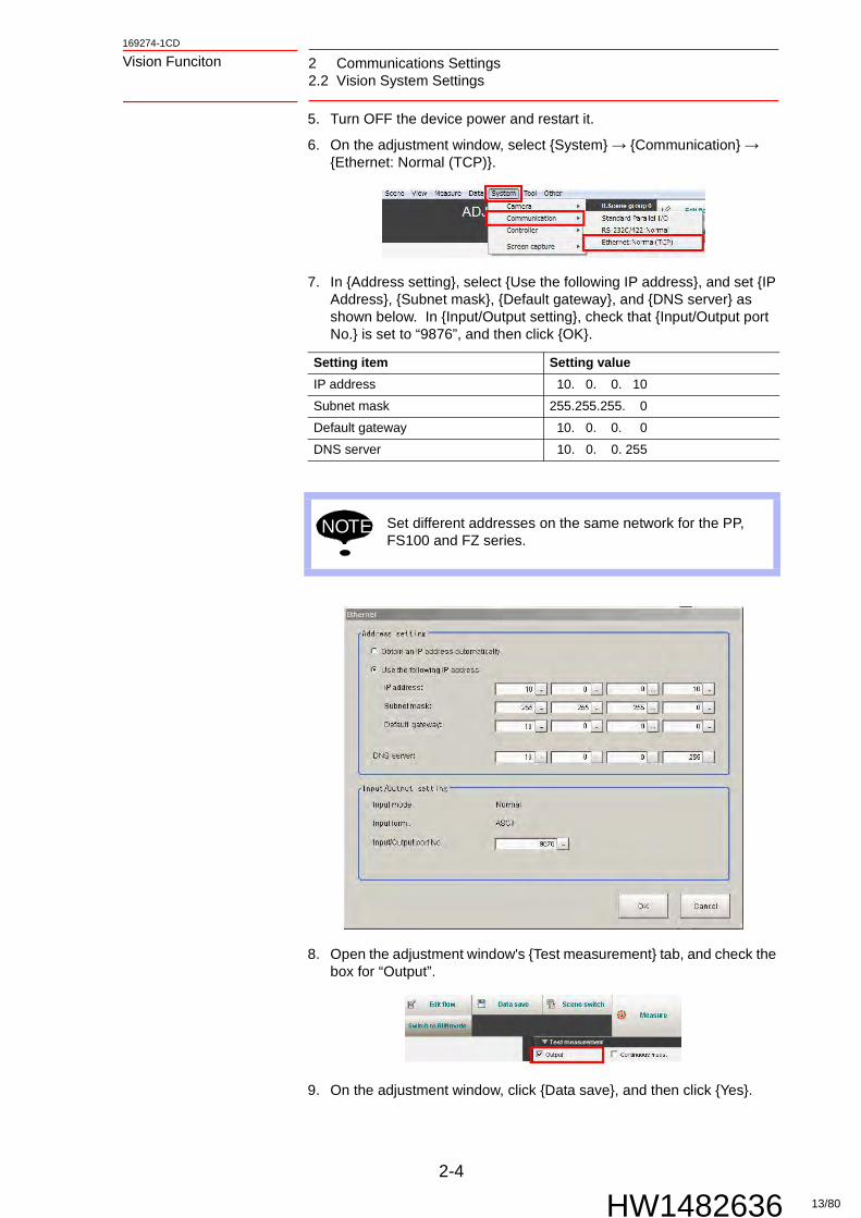
5. Turn OFF the device power and restart it.
6. On the adjustment window, select {System} → {Communication} → {Ethernet: Normal (TCP)}.
7. In {Address setting}, select {Use the following IP address}, and set {IP Address}, {Subnet mask}, {Default gateway}, and {DNS server} as shown below. In {Input/Output setting}, check that {Input/Output port No.} is set to “9876”, and then click {OK}.
8. Open the adjustment window's {Test measurement} tab, and check the box for “Output”.
9. On the adjustment window, click {Data save}, and then click {Yes}.
Setting item Setting value
IP address 10. 0. 0. 10
Subnet mask 255.255.255. 0
Default gateway 10. 0. 0. 0
DNS server 10. 0. 0. 255
NOTE Set different addresses on the same network for the PP, FS100 and FZ series.
13/80
2 Communications Settings2.2 Vision System Settings
2-5
169274-1CD
HW1482636
Vision Funciton
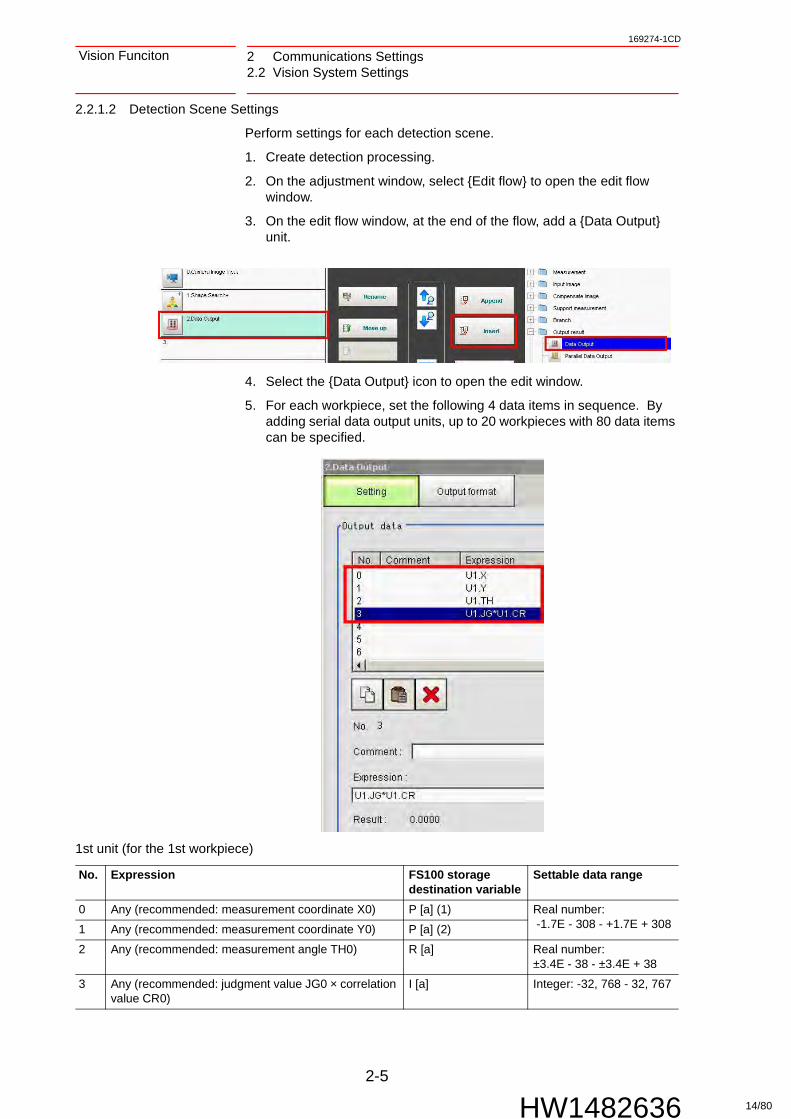
2.2.1.2 Detection Scene Settings
Perform settings for each detection scene.
1. Create detection processing.
2. On the adjustment window, select {Edit flow} to open the edit flow window.
3. On the edit flow window, at the end of the flow, add a {Data Output} unit.
4. Select the {Data Output} icon to open the edit window.
5. For each workpiece, set the following 4 data items in sequence. By adding serial data output units, up to 20 workpieces with 80 data items can be specified.
1st unit (for the 1st workpiece)
No. Expression FS100 storage destination variable
Settable data range
0 Any (recommended: measurement coordinate X0) P [a] (1) Real number: -1.7E - 308 - +1.7E + 3081 Any (recommended: measurement coordinate Y0) P [a] (2)
2 Any (recommended: measurement angle TH0) R [a] Real number: ±3.4E - 38 - ±3.4E + 38
3 Any (recommended: judgment value JG0 × correlation value CR0)
I [a] Integer: -32, 768 - 32, 767
14/80

2-6
169274-1CD
HW1482636
Vision Funciton 2 Communications Settings2.2 Vision System Settings
2nd unit (for the 2nd workpiece)
···
“n” th unit (for the “n” th Workpiece)
The storage destination variable number's [a] is set in the vision condition file.
6. Select the {Output format} tab, and select {Ethernet} for {Communication method}, {Binary} for {Format setting}, and {Refer System (Ethernet)} for {Output IP address setting}.
7. Return to the adjustment window, click {Data save}, and then click {Yes}.
No. Expression FS100 storage destination variable
Settable data range
0 Any (recommended: measurement coordinate X1) P [a + 1] (1) Real number: -1.7E - 308 - +1.7E + 3081 Any (recommended: measurement coordinate Y1) P [a + 1] (2)
2 Any (recommended: measurement angle TH1) R [a + 1] Real number: ±3.4E - 38 - ±3.4E + 38
3 Any (recommended: judgment value JG1 × correlation value CR1)
I [a + 1] Integer: -32, 768 - 32, 767
No. Expression FS100 storage destination variable
Settable data range
0 Any (recommended: measurement coordinate X (n - 1)) P [a + n - 1] (1) Real number: -1.7E - 308 - +1.7E + 3081 Any (recommended: measurement coordinate Y (n - 1)) P [a + n - 1] (2)
2 Any (recommended: measurement angle TH (n - 1)) R [a + n - 1] Real number: ±3.4E - 38 - ±3.4E + 38
3 Any (recommended: judgment value JG (n - 1) × correlation value CR (n - 1))
I [a + n - 1] Integer: -32, 768 - 32, 767
NOTE
• No. 0 to 3 must all be set. Do not set No. 4 to 7.
• If the value set for No. 3 is a positive value, the result for storage destination variable B [a] is increased by 1.
• If the value set for No. 3 is a negative value, the result for storage destination variable B [a] does not change, and then the value converted to a positive number is stored to I [a].
15/80

2 Communications Settings2.2 Vision System Settings
2-7
169274-1CD
HW1482636
Vision Funciton
2.2.1.3 Settings During Operation
Perform settings for automatic operation following powering up.
1. On the adjustment window, select {System} → {Controller} → {Startup setting}.
2. Select the {Basic} tab, and change {Select startup mode} to {RUN}.
3. To startup with a specific detection scene and scene group, check {Specify startup scene, scene group} in {Scene}, and then select a scene group and scene.
4. Click {OK}.
5. On the adjustment window, click {Data save}, and then click {Yes}. If the settings are not saved, upon restart the settings will be initialized.
SUPPLE-MENT
If a startup scene is not set, the scene that was open when {Data save} was clicked will be used for startup.
16/80

2-8
169274-1CD
HW1482636
Vision Funciton 2 Communications Settings2.2 Vision System Settings
2.2.2 COGNEX In-Sight Telnet (Ethernet)
A basic system configuration example for the FS100 vision function (In-Sight) is shown below.
(1) During system operation
NOTE The below shows the In-Sight Micro series as an example.
No. Required device No. of items
In-Sight/In-Sight Micro series 1
Vision View 1
FS100 1
24V power supply unit 1
In-Sight proprietary Ethernet cable 1
Ethernet cable (straight)/for PC connection 1
In-Sight proprietary power cable (For In-Sight 5000 series only) 1
PC with In-Sight Explorer installed 1
Ethernet cable (straight)/for PC connection 1
17/80

2 Communications Settings2.2 Vision System Settings
2-9
169274-1CD
HW1482636
Vision Funciton
(2) During setup
2.2.2.1 VisionView Settings
Perform these settings to use VisionView.
1. On the interface window click {Options} and select {VIsionView Setup}.
2. Click {Settings}, and select {Network Settings}.
3. Click {Set IP Address Manually}, and select {Edit Settings}.
4. Click {Edit}, and set the IP address and subnet mask.
5. Select {OK}.
Setting item Setting value
IP address 10. 0. 0. 100 (Recommended)
Subnet mask 255.255.255. 0
NOTE Set different addresses on the same network for the PC, Vision View, the robot controller, and In-Sight.
18/80

2-10
169274-1CD
HW1482636
Vision Funciton 2 Communications Settings2.2 Vision System Settings
6. On the interface window click {Options} and select {VIsionView Setup}.
7. Select {Manually Select Sensors}.
8. Select the In-Sight connected to a detected sensor, and then select {Add}.
9. Line up the cursor with the In-Sight to use, and then select {OK}.
<Explanation of Interface>
Displays the currently opened job name. Displays the current status. Switches between Online and Offline. To perform communication,
set to Online. {Focus}: Displays the live image. Use when setting the lens focus
and exposure. {Trigger}: Performs image reading and detection processing. {Switch View}: Switches between the image display, image +
detection result display, and image + detection result + custom view display.
{Options}: Change Vision View settings and switch/save jobs. {Custom View}: The interface that is set for the camera job. Simple
vision adjustments, such as recognition thresholds, can be performed.
SUPPLE-MENT
If a sensor is not detected, set up the system first.
19/80

2 Communications Settings2.2 Vision System Settings
2-11
169274-1CD
HW1482636
Vision Funciton
2.2.2.2 System Settings
Perform settings on the vision system only after returning its settings to the default factory values.
1. Start In-Sight Explorer on the PC. From the menu bar, select {System}, and then select {Add Sensor/Device to Network}.
2. Select a connected In-Sight, and perform the settings as follows in the right side of the window.
NOTE
• Vision function camera jobs used for the vision function (In-Sight) are made using the following firmware version. If the camera's version is lower than the version below, camera jobs may not be read correctly.
• The Windows application "In-Sight Explorer" by Cognex is used to set up the vision function (In-Sight). Download the Cognex In-Sight Software 4.5.0.exe from the Cognex web site, and install it onto the PC.
Setting item Setting value
Host name InSightMicro
IP address 10. 0. 0. 210
Subnet mask 255.255.255. 0
In-Sight firmware version 4.05.00
20/80
2-12
169274-1CD
HW1482636
Vision Funciton 2 Communications Settings2.2 Vision System Settings
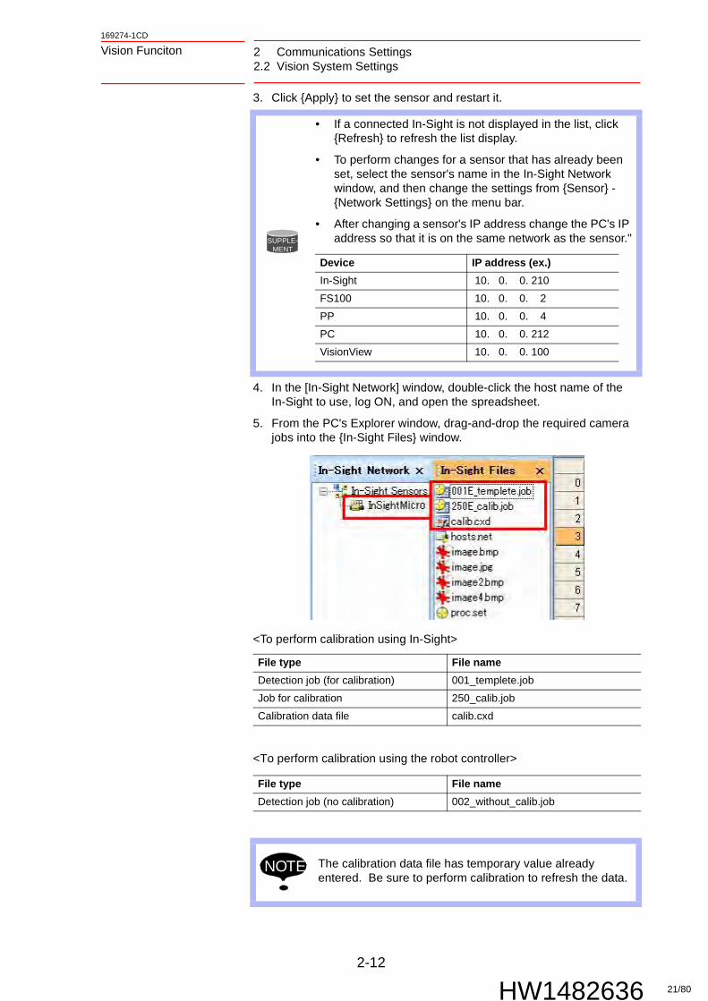
3. Click {Apply} to set the sensor and restart it.
4. In the [In-Sight Network] window, double-click the host name of the In-Sight to use, log ON, and open the spreadsheet.
5. From the PC's Explorer window, drag-and-drop the required camera jobs into the {In-Sight Files} window.
<To perform calibration using In-Sight>
<To perform calibration using the robot controller>
SUPPLE-MENT
• If a connected In-Sight is not displayed in the list, click {Refresh} to refresh the list display.
• To perform changes for a sensor that has already been set, select the sensor's name in the In-Sight Network window, and then change the settings from {Sensor} - {Network Settings} on the menu bar.
• After changing a sensor's IP address change the PC's IP address so that it is on the same network as the sensor."
File type File name
Detection job (for calibration) 001_templete.job
Job for calibration 250_calib.job
Calibration data file calib.cxd
File type File name
Detection job (no calibration) 002_without_calib.job
NOTE The calibration data file has temporary value already entered. Be sure to perform calibration to refresh the data.
Device IP address (ex.)
In-Sight 10. 0. 0. 210
FS100 10. 0. 0. 2
PP 10. 0. 0. 4
PC 10. 0. 0. 212
VisionView 10. 0. 0. 100
21/80

2 Communications Settings2.2 Vision System Settings
2-13
169274-1CD
HW1482636
Vision Funciton
6. From the menu bar, select {Sensor} → {Startup}.
7. Check the box for {Online}, and in {Job}, select the job to open when the power is turned ON, and then click {OK}.
SUPPLE-MENT
• If the window shows Easy Builder, in the {In-Sight Network} window, right-click the host name of the In-Sight to use, and then select {View}→{Show Spreadsheet View} to open the spreadsheet.
• If the {In-Sight Files} tab is not displayed, enable {In-Sight Files} from {View} on the menu bar.
22/80

2-14
169274-1CD
HW1482636
Vision Funciton 2 Communications Settings2.2 Vision System Settings
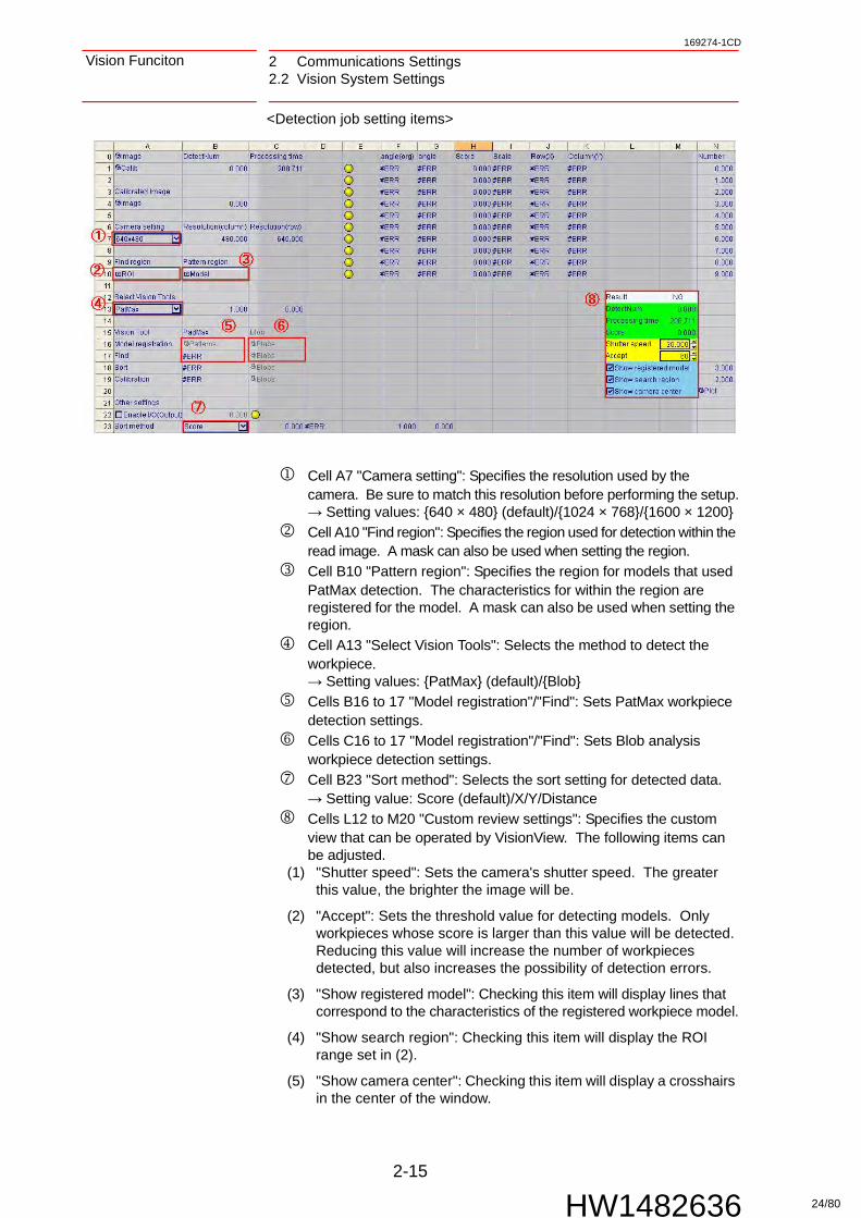
2.2.2.3 Camera Job Specifications
A proprietary camera job is used for communication between the robot controller and In-Sight. Other jobs, and jobs created in EasyBuilder may not be correctly transmitted to the robot.
When vision system receives a command from the robot controller, the data in the cells of the spreadsheet are overwritten. The position of the cells that are referenced during writing are as follows.
Cell B1, "DetectNum": Displays the number of workpieces detected in 1 trigger. A maximum of 10 items can be detected.→ Variable B (default setting: B090)
Cells F1 to F10 "angle(org)": Displays the amount of offset angle for the detected workpiece against the registered model.→ Variable R (default setting: R090 to 099)
Cells H1 to H10 "Score": Displays the score (correlation value) for the detected workpiece against the registered model.→ Variable I (default setting: I090 to 099)
Cells J1 to J10/K1 to K10 "Row(X)"/"Column(Y)": Displays the position (X, Y) of the detected workpiece. If calibration is performed for In-Sight, X and Y correspond to the user's input coordinates. Without calibration, the camera's pixel coordinates are output.→ Variable P (default setting: P110 to 119)
The storage destination variable number's [a] is set in the vision condition file.
NOTE Do not change the referenced cells during writing. Communication may not be performed correctly.
23/80
2 Communications Settings2.2 Vision System Settings
2-15
169274-1CD
HW1482636
Vision Funciton
<Detection job setting items>
Cell A7 "Camera setting": Specifies the resolution used by the camera. Be sure to match this resolution before performing the setup.→ Setting values: {640 × 480} (default)/{1024 × 768}/{1600 × 1200}
Cell A10 "Find region": Specifies the region used for detection within the read image. A mask can also be used when setting the region.
Cell B10 "Pattern region": Specifies the region for models that used PatMax detection. The characteristics for within the region are registered for the model. A mask can also be used when setting the region.
Cell A13 "Select Vision Tools": Selects the method to detect the workpiece.→ Setting values: {PatMax} (default)/{Blob}
Cells B16 to 17 "Model registration"/"Find": Sets PatMax workpiece detection settings.
Cells C16 to 17 "Model registration"/"Find": Sets Blob analysis workpiece detection settings.
Cell B23 "Sort method": Selects the sort setting for detected data.→ Setting value: Score (default)/X/Y/Distance
Cells L12 to M20 "Custom review settings": Specifies the custom view that can be operated by VisionView. The following items can be adjusted.
(1) "Shutter speed": Sets the camera's shutter speed. The greater this value, the brighter the image will be.
(2) "Accept": Sets the threshold value for detecting models. Only workpieces whose score is larger than this value will be detected. Reducing this value will increase the number of workpieces detected, but also increases the possibility of detection errors.
(3) "Show registered model": Checking this item will display lines that correspond to the characteristics of the registered workpiece model.
(4) "Show search region": Checking this item will display the ROI range set in (2).
(5) "Show camera center": Checking this item will display a crosshairs in the center of the window.
24/80

2-16
169274-1CD
HW1482636
Vision Funciton 2 Communications Settings2.2 Vision System Settings
<Calibration job setting items>
Cell A1 "Calib": Performs calibration. The detection job reads the calibration data saved in the camera, which is shown into this cell.
2.2.2.4 Object Type Settings
1. Start In-Sight Explorer on the PC.
2. In the {In-Sight Network} window, double-click the host name of the In-Sight to use and log ON.
3. Copy the existing camera job to the PC and modify the file name to {[registering object type (using 3-digit single-byte letters)]_[any character string]}". Then, copy it to the In-Sight.
NOTE
• The file created during calibration called "calib.cxd" is set to be shared and used with all detection jobs. Before using, be sure to perform calibration, which will overwrite the data in this file.
• If the above file is not found in the camera, an error will occur, and detection may not be performed normally. Do not change the file name or delete the file.
NOTE
• The initial 3-digit number is the controller's detection model number.
• Do not create files with the same detection model number.
• It is recommended that the file name contains only single-byte letters and numbers.
• The In-Sight vision system requires at least 10 seconds to switch between camera jobs (when performing a calibration using cameras).
25/80

2 Communications Settings2.2 Vision System Settings
2-17
169274-1CD
HW1482636
Vision Funciton
4. Open the added job on the {In-Sight Files} window.
5. Place the workpiece in the center of the camera's field-of-view, and then select {Image} → {Trigger} from the menu bar to read the image of the sample workpiece.
6. Select “Model” in cell B10 to set the part to detect. After setting is complete, double-click within the region to return to the previous window.
7. Select “ROI” in cell A10 to set the detection range. Workpiece detection will only be performed in the set range. After setting is complete, double-click within the region to return to the previous window.
SUPPLE-MENT
• Register a part within the region that includes as little of the background as possible. Showing too much of the background may cause incorrect detection.
• A mask can be used when setting the region. For details, refer to the In-Sight's help.
26/80

2-18
169274-1CD
HW1482636
Vision Funciton 2 Communications Settings2.2 Vision System Settings
8. Double-click “Patterns” in cell B16 to open the properties sheet, and remove the check next to “Reuse Training Image”. Then, re-check the box, and then click {OK}.
9. Select {Image}→{Trigger} from the menu bar. When the trigger is executed, confirm that the workpiece is detected and that the information in the cells in the first row, such as F1 and G1, are refreshed with the workpiece's information.
10. Select {File} → {Save Job} from the menu bar to save the job.
NOTE If another job is opened or In-Sight Explorer is closed before saving, any changes that were made will be lost.
27/80
2 Communications Settings2.2 Vision System Settings
2-19
169274-1CD
HW1482636
Vision Funciton
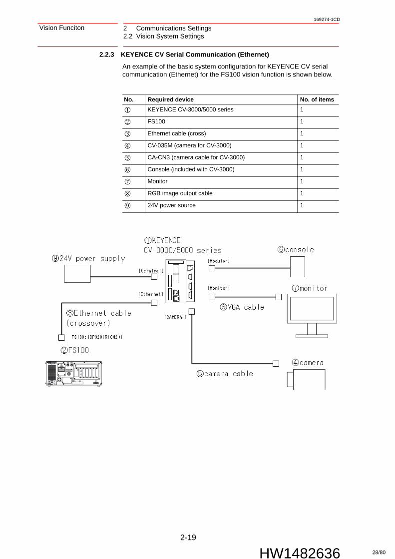
2.2.3 KEYENCE CV Serial Communication (Ethernet)
An example of the basic system configuration for KEYENCE CV serial communication (Ethernet) for the FS100 vision function is shown below.
No. Required device No. of items
KEYENCE CV-3000/5000 series 1
FS100 1
Ethernet cable (cross) 1
CV-035M (camera for CV-3000) 1
CA-CN3 (camera cable for CV-3000) 1
Console (included with CV-3000) 1
Monitor 1
RGB image output cable 1
24V power source 1
28/80

2-20
169274-1CD
HW1482636
Vision Funciton 2 Communications Settings2.2 Vision System Settings
2.2.3.1 System Settings
Perform settings on the vision system only after returning its settings to the default factory values.
1. If on the {RUN} window, switch to the {PROG} window using the console's {RUN/STOP} slider.
2. Select {Global} → {Ethernet Network Settings}.
3. Set the {Ethernet Network Settings} as shown below.
Setting item Setting value
IP address 010.000.000.010
Subnet mask 255.255.255.000 (system default value)
Default gateway 000.000.000.000 (system default value)
Enable BOOTP Unchecked (system default value)
Port number for data 08500 (system default value)
Delimiter CR (system default value)
29/80

2 Communications Settings2.2 Vision System Settings
2-21
169274-1CD
HW1482636
Vision Funciton
4. Select {OK} to return to the previous window.
5. Press the {FUNCTION} button on the console to open the {Function}. Select {Execute} for {Save settings}, and then {OK} to save the settings.
2.2.3.2 Object Type Settings
1. If on the {RUN} window, switch to the {PROG} window using the console's {RUN/STOP} slider.
2. Select {PROGXXX (number of the object type opened)}, which will load the object type's settings so that settings can be performed.
3. Create detection settings.
4. In the {Edit} column, open {Output} → {Ethernet (TCP/IP)}.
NOTE Set different addresses on the same network for the PP, FS100 and CV series.
30/80
2-22
169274-1CD
HW1482636
Vision Funciton 2 Communications Settings2.2 Vision System Settings
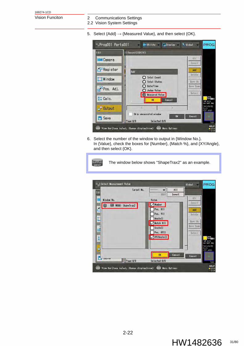
5. Select {Add} → {Measured Value}, and then select {OK}.
6. Select the number of the window to output in {Window No.}. In {Value}, check the boxes for {Number}, {Match %}, and {XY/Angle}, and then select {OK}.
SUPPLE-MENT
The window below shows "ShapeTrax2" as an example.
31/80

2 Communications Settings2.2 Vision System Settings
2-23
169274-1CD
HW1482636
Vision Funciton
7. Check that the output order for {Ethernet (TCP/IP)} is {Number}, {Match %}, and {Pos. X,Pos.Y,Angle}, and then select {OK}.
8. In the {Edit} column, select {Save} and then {OK} to save the settings.
SUPPLE-MENT
The five following data items can be output in 1 window. Set all five for each window.
The storage destination variable number's [a] is set in the vision condition file.
No. Setting data FS100 storage destination variable
Settable data range
0 Any (recommended: detection number)
B [a + 0] Integer: 0 to 255
1 Any (recommended: correlation value)
I [a + 0] Integer: -32, 768 - 32, 767
2 Any (recommended: X position)
P [a + 0] (1) Real number: ±1.7E - 308 - +1.7E + 308
3 Any (recommended: Y position)
P [a + 0] (2)
4 Any (recommended: angle)
R [a + 0] Real number: ±3.4E - 38 - ±3.4E + 38
32/80

2-24
169274-1CD
HW1482636
Vision Funciton 2 Communications Settings2.2 Vision System Settings
2.2.4 KEYENCE XG Serial Communication (Ethernet)
An example of the basic system configuration for KEYENCE XG serial communication (Ethernet) for the FS100 vision function is shown below.
No. Required device No. of items
KEYENCE XG-7000 series 1
FS100 1
Ethernet cable (cross) 1
XG-035M (camera for XG-7000) 1
CA-CN3 (camera cable for XG-7000) 1
OP-84231 (Console for XG-7000) 1
Monitor 1
RGB image output cable 1
24V power source 1
33/80
2 Communications Settings2.2 Vision System Settings
2-25
169274-1CD
HW1482636
Vision Funciton
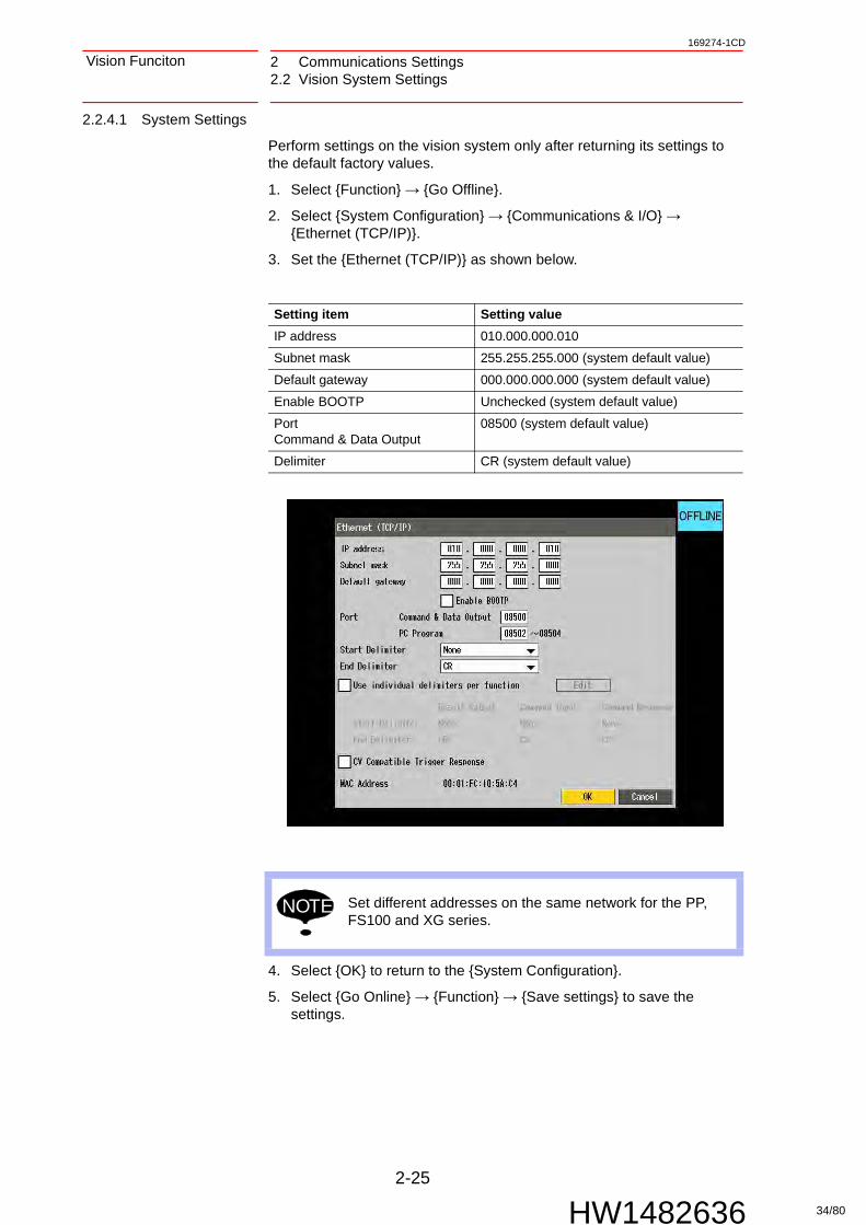
2.2.4.1 System Settings
Perform settings on the vision system only after returning its settings to the default factory values.
1. Select {Function} → {Go Offline}.
2. Select {System Configuration} → {Communications & I/O} → {Ethernet (TCP/IP)}.
3. Set the {Ethernet (TCP/IP)} as shown below.
4. Select {OK} to return to the {System Configuration}.
5. Select {Go Online} → {Function} → {Save settings} to save the settings.
Setting item Setting value
IP address 010.000.000.010
Subnet mask 255.255.255.000 (system default value)
Default gateway 000.000.000.000 (system default value)
Enable BOOTP Unchecked (system default value)
PortCommand & Data Output
08500 (system default value)
Delimiter CR (system default value)
NOTE Set different addresses on the same network for the PP, FS100 and XG series.
34/80
2-26
169274-1CD
HW1482636
Vision Funciton 2 Communications Settings2.2 Vision System Settings
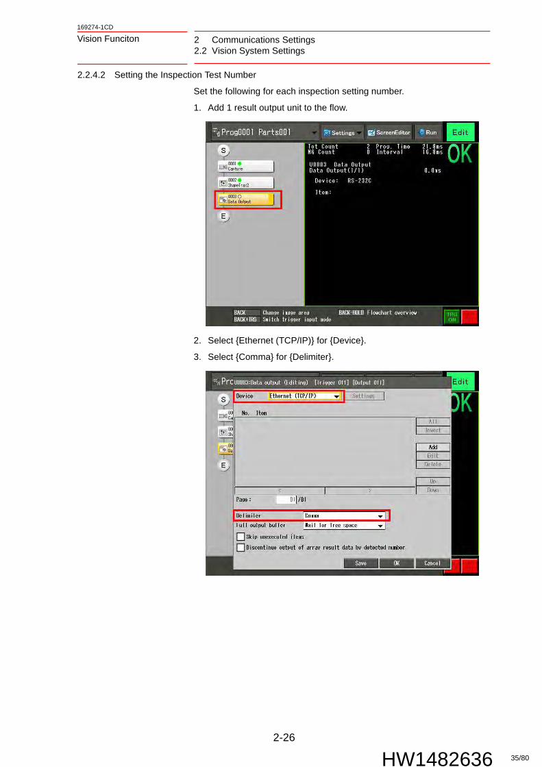
2.2.4.2 Setting the Inspection Test Number
Set the following for each inspection setting number.
1. Add 1 result output unit to the flow.
2. Select {Ethernet (TCP/IP)} for {Device}.
3. Select {Comma} for {Delimiter}.
35/80

2 Communications Settings2.2 Vision System Settings
2-27
169274-1CD
HW1482636
Vision Funciton
4. Set the output data in {Item} in the following order.
The relationships between the output data and the variable's storage locations are as follows.
Required data
The [a] of the variable numbers are set in the "Vision condition file" which can be set using the programming pendant.
Added data
Setting is possible up to n=19 (equals detection results for 20 workpieces). When adding, be sure to add one workpiece (with 4 data items) at a time.
No. Expression FS100 storage destination variable
Settable data range
0 Any (recommended: detection number) B [a + 0] Integer: 0 to 255
1 Any (recommended: correlation value 0) I [a + 0] Integer: -32, 768 - 32, 767
2 Any (recommended: X0 position) P [a + 0] (1) Real number: -1.7E - 308 - +1.7E + 308
3 Any (recommended: Y0 position) P [a + 0] (2)
4 Any (recommended: angle 0) R [a + 0] Real number: -3.4E - 38 - ±3.4E + 38
No. Expression FS100 storage destination variable
Settable data range
5 Any (recommended: correlation value 1) I [a + 1] Integer: -32, 768 - 32, 767
6 Any (recommended: X1 position) P [a + 1] (1) Real number: -1.7E - 308 - +1.7E + 308
7 Any (recommended: Y1 position) P [a + 1] (2)
8 Any (recommended: angle 1) R [a + 1] Real number: -3.4E - 38 - ±3.4E + 38
··· ··· ··· ···
4n + 1 Any (recommended: correlation value n) I [a + n] Integer: -32, 768 - 32, 767
4n + 2 Any (recommended: Xn position) P [a + n] (1) Real number: -1.7E - 308 - +1.7E + 308
4n + 3 Any (recommended: Yn position) P [a + n] (2)
4n + 4 Any (recommended: angle n) P [a + n] Real number: -3.4E - 38 - ±3.4E + 38
36/80

2-28
169274-1CD
HW1482636
Vision Funciton 2 Communications Settings2.2 Vision System Settings
SUPPLE-MENT
• The output settings for the results of "ShapeTrax2" are shown as an example.
Required data: perform the following settings.
No. Expression Remarks
0 RSLT. N: MS Number of detections
1 RSLT. C [0] Workpiece 0: Correlation value
2 RSLT. X [0]: MS *The below format is also permitted
RSLT. XYT [0]: MS
Workpiece 0: X coordinate
3 RSLT. Y [0]: MS Workpiece 0: Y coordinate
4 RSLT. T [0]: MS Workpiece 0: Rotation offset amount
37/80

2 Communications Settings2.2 Vision System Settings
2-29
169274-1CD
HW1482636
Vision Funciton
SUPPLE-MENT
Added data: perform the following settings when 2 or more workpieces are to be detected.
No. Expression Remarks
5 RSLT. C [1] Workpiece 1: Correlation value
6 RSLT. X [1]: MS *The below format is also permitted
RSLT. XYT [1]: MS
Workpiece 1: X coordinate
7 RSLT. Y [1]: MS Workpiece 1: Y coordinate
8 RSLT. T [1]: MS Workpiece 1: Rotation offset amount
··· ··· ···
4n + 1 RSLT. C [n] Workpiece n: Correlation value
4n + 2 RSLT. X [n]: MS *The below format is also permitted
RSLT. XYT [n]: MS
Workpiece n: X coordinate
4n + 3 RSLT. Y [n]: MS Workpiece n: Y coordinate
4n + 4 RSLT. T [n]: MS Workpiece n: Rotation offset amount
38/80

2-30
169274-1CD
HW1482636
Vision Funciton 2 Communications Settings2.2 Vision System Settings
2.2.5 SHARP IV-S200 Serial Communication (Ethernet)
An example of the basic system configuration for SHARP IV-S200 serial communication (Ethernet) for the FS100 vision function is shown below.
No. Required device No. of items
SHARP IV-S200 series 1
FS100 1
Ethernet cable (cross) 1
IV-S200C6 (camera for IV-S200) 1
IV-S200K3 (camera cable for IV-S200) 1
IV-S200RK (Remote setting key for IV-S200RK) 1
Monitor 1
RGB image output cable 1
24V power source 1
39/80

2 Communications Settings2.2 Vision System Settings
2-31
169274-1CD
HW1482636
Vision Funciton
2.2.5.1 System Settings
Perform settings on the vision system only after returning its settings to the default factory values.
1. Press [MODE] button of the remote setting key to open the mode switching window, and then select {Settings}.
2. Press [SET] button of the remote setting key, and then in the settings window, select {System settings} → {Ethernet settings}.
3. Set the following in the {IP} tab.
Setting item Setting value
IP Address 010.000.000.020 (system default value)
Subnet mask 255.255.255.000 (system default value)
Default gateway 010.000.000.001 (system default value)
NOTE Set different addresses on the same network for the PP, FS100 and IV-S200 series.
40/80

2-32
169274-1CD
HW1482636
Vision Funciton 2 Communications Settings2.2 Vision System Settings
4. Set the following in the {Port} tab.
5. Set the following in the {Other} tab.
2.2.5.2 Setting the Object Type Setting Number
Perform settings for each object type setting number.
1. Press [SET] button of the remote setting key to open the settings windows, and select {Object type setting} → {Object selection. . . } → {BLOCK0X (select a block)} → {H0XXX (the object type to set)}.
2. Return to {Object type setting}, and then select {Module setting}.
Setting item Setting value
Transmission port 2000 (system default value)
Reception port 2001 (system default value)
Setting item Setting value
Terminal number 000 (system default value)
41/80

2 Communications Settings2.2 Vision System Settings
2-33
169274-1CD
HW1482636
Vision Funciton
3. Select {M000(trigger)}, set {Select a trigger} to {External trigger}, and then check the box for {Ethernet} in {External trigger setting...}.
4. Create detection processing.
5. On the module selection window, just before {END}, create and select the necessary number of {CALC} units, and then perform the following settings.
Placement order
{Calculation setting... } → {Formula} {Effective decimal places}
Settable data range FS100 storage destination variable
1 {Constant. . . } → {N(The same number set for maximum detections in the vision file)}
0 1 to 18 - (No storage destination)
2 Any (recommended: detection number) 0 Integer: 0 to 255 B [a]
The following are settings for each of the number of units specified in placement order 1.3 Any (recommended: matching to workpiece 0) 0 Integer: -32, 768 - 32, 767 I [a]
4 Any (recommended: matching to workpiece 1) 0 Integer: -32, 768 - 32, 767 I [a + 1]
··· ··· ···
N+2 Any (recommended: matching to workpiece N-1)
I [a + n]
N+3 Any (recommended: offset X workpiece 0) 3 Real number: ±3.4E - 38 - ±3.4E + 38
P [a] (1)
··· ··· ···
N+3 Any (recommended: offset X workpiece N-1) P [a] (1)
2N+3 Any (recommended: offset Y workpiece 0) 3 Real number: ±3.4E - 38 - ±3.4E + 38
P [a] (2)
··· ··· ···
2N+3 Any (recommended: offset Y workpiece N-1) P [a] (2)
3N+3 Any (recommended: relative angle workpiece 0)
3 Real number: ±1.7E - 308 - ±1.7E + 308
R [a]
··· ··· ···
4N+2 Any (recommended: relative angle workpiece N-1)
R [a + n]
42/80

2-34
169274-1CD
HW1482636
Vision Funciton 2 Communications Settings2.2 Vision System Settings
The storage destination variable number's [a] is set in the vision condition file.
NOTEThe maximum number of detections is 18. Decide the number of labels according to the number of set output items.
43/80

2 Communications Settings2.2 Vision System Settings
2-35
169274-1CD
HW1482636
Vision Funciton
SUPPLE-MENT
As a reference, the output settings for data for frame search for 1 workpiece , and 3 workpieces are shown below. Variable storage destinations are set to their defaults. Data output settings for 1 workpiece
Order Name {Effective decimal places}
{Calculation setting... } → {Formula} FS100 storage destination
1 Number output 0 {Constant}→{1} - (No storage destination)
2 Number of detections
0 {Measured value}→{(frame search)}→ {Measured value}→{Detection number}
B090
3 Matching to workpiece 0
0 {Measured value}→{(frame search)}→ {Measured value}→{Matching level}→ {Label 0}
I090
4 Offset X workpiece 0
3 {Measured value}→{(frame search)}→ {Measured value}→{X offset}→{Label 0}
P110 (1)
5 Offset Y workpiece 0
3 {Measured value}→{(frame search)}→ {Measured value}→{Y offset}→{Label 0}
P110 (2)
6 Relative angle workpiece 0
3 {Measured value}→{(frame search)}→ {Measured value}→{Relative angle}→ {Label 0}
R090
44/80

2-36
169274-1CD
HW1482636
Vision Funciton 2 Communications Settings2.2 Vision System Settings
SUPPLE-MENT
Data output settings for 3 workpiece
Order Name [Effective decimal places]
{Calculation setting... } → {Formula} FS100 storage destination
1 Number output 0 {Constant}→{10} - (No storage destination)
2 Number of detections
0 {Measured value}→{(frame search)}→ {Measured value}→{Detection number}
B090
3 Matching to workpiece 0
0 {Measured value}→{(frame search)}→ {Measured value}→{Matching level}→ {Label 0}
I090
4 Matching to workpiece 1
0 {Measured value}→{(frame search)}→ {Measured value}→{Matching level}→ {Label 1}
I091
5 Matching to workpiece 2
0 {Measured value}→{(frame search)}→ {Measured value}→{Matching level}→ {Label 2}
I092
6 Offset X workpiece 0
3 {Measured value}→{(frame search)}→ {Measured value}→{X offset}→{Label 0}
P110 (1)
7 Offset X workpiece 1
3 {Measured value}→{(frame search)}→ {Measured value}→{X offset}→{Label 1}
P111 (1)
8 Offset X workpiece 2
3 {Measured value}→{(frame search)}→ {Measured value}→{X offset}→{Label 2}
P112 (1)
9 Offset Y workpiece 0
3 {Measured value}→{(frame search)}→ {Measured value}→{Y offset}→{Label 0}
P110 (2)
10 Offset Y workpiece 1
3 {Measured value}→{(frame search)}→ {Measured value}→{Y offset}→{Label 1}
P111 (2)
11 Offset Y workpiece 2
3 {Measured value}→{(frame search)}→ {Measured value}→{Y offset}→{Label 2}
P112 (2)
12 Relative angle workpiece 0
3 {Measured value}→{(frame search)}→ {Measured value}→{Relative angle}→ {Label 0}
R090
13 Relative angle workpiece 1
3 {Measured value}→{(frame search)}→ {Measured value}→{Relative angle}→ {Label 1}
R091
14 Relative angle workpiece 2
3 {Measured value}→{(frame search)}→ {Measured value}→{Relative angle}→ {Label 2}
R092
45/80

2 Communications Settings2.2 Vision System Settings
2-37
169274-1CD
HW1482636
Vision Funciton
6. Return to {Object type setting}, and then select {Output settings... } →{Data output settings}.
7. Set the following in the {Output operation} tab.
Setting item Setting value
Output timing Each trigger
Output location Ethernet
46/80

2-38
169274-1CD
HW1482636
Vision Funciton 2 Communications Settings2.2 Vision System Settings
8. Set the following in the {Data selection} tab.
Setting item Setting value
Object type number On
Number of times to measure Off
Number of times to OK Off
Number of times to NG Off
Number of times to Error Off
Total evaluation On
Select measurement... Check all value calculation units("OutputNum" to "Co-angleN")
[Confirm the output] 2+2+4 X N pieces2 (object type number, total evaluation)+2 (number output, number of detections)+4 X N (matching level, X,Y offsets, relative angle for each workpiece)
47/80

2 Communications Settings2.3 Vision Condition File Settings
2-39
169274-1CD
HW1482636
Vision Funciton
2.3 Vision Condition File Settings
Perform settings for vision condition files used for detection jobs. Vision condition files specify the variable numbers stored for the offsets detected by the camera.
1. Select {VISION CONDITION} in {OPTION}.
2. Change the page to select the number of the file to use, and change {COORDINATE} from {ROBOT} to {PIXEL}.
3. Input the number of data that are output by the vision system as set in {RESULT MAX NO.}.
4. Specify a variable number in {VARIABLE FOR RESULT}. Numbers for variables other than B will be stored up the number specified in {RESULT MAX NO.}. The maximum value for {RESULT MAX NO.} depends on the communication configuration.
Change to [PIXEL]
Specify the number of results to acquire
Specify the data storage location
NOTEIf variables that are stored as data exceed the defined ranges of the system, during vision command execution the alarm: WRONG EXECUTION OF VISION INST [2] occurs. In such cases, set {VARIABLE FOR RESULT} and {RESULT MAX NO.} correctly.
SUPPLE-MENT
For vision condition file details, refer to Section 5.1 “Vision Condition Files” on page 5-1.
48/80

2-40
169274-1CD
HW1482636
Vision Funciton 2 Communications Settings2.4 Setting Parameters and Variables
2.4 Setting Parameters and Variables
2.4.1 Setting Parameters
Set RS parameters for each communication configuration, as shown below.
Connection method Parameter Setting value
OMRON serial communication (Ethernet) RS109 16RS460 10RS461 0RS462 0RS463 10
COGNEX In-sight Telnet (Ethernet) RS104 255RS109 12RS460 10RS461 0RS462 0RS463 210
KEYENCE CV serial communication (Ethernet) RS109 13RS460 10RS461 0RS462 0RS463 10
KEYENCE XG serial communication (Ethernet) RS109 17RS460 10RS461 0RS462 0RS463 10
SHARP IV-S serial communication (Ethernet) RS109 11RS460 10RS461 0RS462 0RS463 20
SUPPLE-MENT
For parameter details, refer to Chapter 7 "Parameter List".
49/80

2 Communications Settings2.4 Setting Parameters and Variables
2-41
169274-1CD
HW1482636
Vision Funciton
2.4.2 Setting Variables
Initialize with the data storage destination P variable type set to anything except {PULSE}. Set the number of variable specified in {RESULT MAX NO.} in order from the position variable number specified in the vision condition file (default value for P: 110).
(Example) When the vision condition file specification for {FIND POS. (P -VAR.)} is 110, P[110 to P119] is initialized.
NOTE If the type specification is undefined, during vision command execution the alarm: WRONG EXECUTION OF VISION INST [9] occurs.
50/80

3-1
169274-1CD
HW1482636
Vision Funciton 3 Detection Job Creation and Execution3.1 Job for Detection Result Storage
3 Detection Job Creation and Execution
3.1 Job for Detection Result Storage
Create a detection job for performing communication with the vision system.
Detection job examples are shown below.
NOTE
• The VSTART function differs for each communicating vision system's settings. For details, refer to Section 4.1 onwards.
• To perform robot operation adjustments using the results received, additional calibration and calculation is required.
Specifies the number of retries.
The initialization of variable ranges used for the VSTART command are carried out in the job, so input the setting values into the vision file.
Executes the initialization of the variable ranges used for the VSTART command.
TOOL23 is used as a vision tool for storing detection results.
51/80

3 Detection Job Creation and Execution3.2 Job for Part Type Changing
3-2
169274-1CD
HW1482636
Vision Funciton
3.2 Job for Part Type Changing
Sets the retry conditions.
Executes a "trigger+store results" command. Set the FT and MD tags after confirming the functions of each vision system.The detection results are stored to the vision condition file’s specified variables.
Executes a "part type change" command. Set the CND tags after confirming the functions of each vision system.
52/80

4-1
169274-1CD
HW1482636
Vision Funciton 4 List of Robot Language (INFORM III) Commands
4 List of Robot Language (INFORM III) Commands
VSTART Function Executes processing for the related vision function.
Appended item FIND
FT = <Detection type>MD = <Detection model number>VF# (<Vision condition file number>)
FT: 0 to 255MD: 0 to 7VF#: 1 to 32
SELCND
CND = <Detection scene number> CND: 0 to 255
CALIB
CALF# (<Calibration file number>) CALF#: 1 to 16
Usage example VSART FIND FT = 0 MD = 0 VF# (1)VWAIT
VWAIT Function Waits for the end of processing related to vision functions.
Appended item None
Usage example VSART FIND FT = 0 MD = 0 VF# (1)VWAIT
NOTE
• The VSTART function differs for each communicating vision system's settings. For details, refer to Section 4.1 onwards.
• After the execution of VSTART FIND, and until the execution of VWAIT, do not under any circumstances load or write to the storage variables specified by the vision file. Doing so can cause an operational error.
53/80

4 List of Robot Language (INFORM III) Commands4.1 OMRON FZ Serial Communication (Ethernet)
4-2
169274-1CD
HW1482636
Vision Funciton
4.1 OMRON FZ Serial Communication (Ethernet)
4.1.1 Usage Example
(1) Scene switch → image → data acquisition
• ExplanationThe scene number specified in {FT} is loaded and video capture is performed. Then, the first vision file {VARIABLE FOR RESULT} B, I, R, and P variable data is stored.
Function designation
Additional parameters Function
FIND FT:Detection type number
MD:Detection model number
VF# ():Vision file number
0 to 311) * 2) 1 to 32 After switching to the {FT} scene number, the image and detection results are acquired.* Maximum 20 individual detection results
SELCND CND: Detection scene number
0 to 311) Switch to the {CND} scene group number
CALIB CALF# (): Calibration file number
1 to 16 {CALF#} data is used to perform camera calibration
1 If executed using 32 to 255, an alarm will occur.2 It is possible to execute with any values for disabled parameters not related to processing.
Variable Contents
B [0] Number of detections
I [0] Workpiece 0: Correlation value
R [0] Workpiece 0: Rotation offset amount
P [0] (1): (X coordinate) Workpiece 0: X coordinate
P [0] (2): (Y coordinate) Workpiece 0: Y coordinate
··· ···
SUPPLE-MENT
• Of the number of B [0] detections sent to I [0] to [19], the number of positive values is stored.
• If the data sent to I[0] to [19] is negative, it will be automatically corrected to be positive. If negative, it will not be counted for the detection number for B[0] described above.
JOB:16-V FIND0000 NOP0001 VSTART FIND FT=1 MD=0 VF#(1)0002 VWAIT0003 END
Any value OK
Scene number Applies to vision file 1
54/80
4-3
169274-1CD
HW1482636
Vision Funciton 4 List of Robot Language (INFORM III) Commands4.1 OMRON FZ Serial Communication (Ethernet)
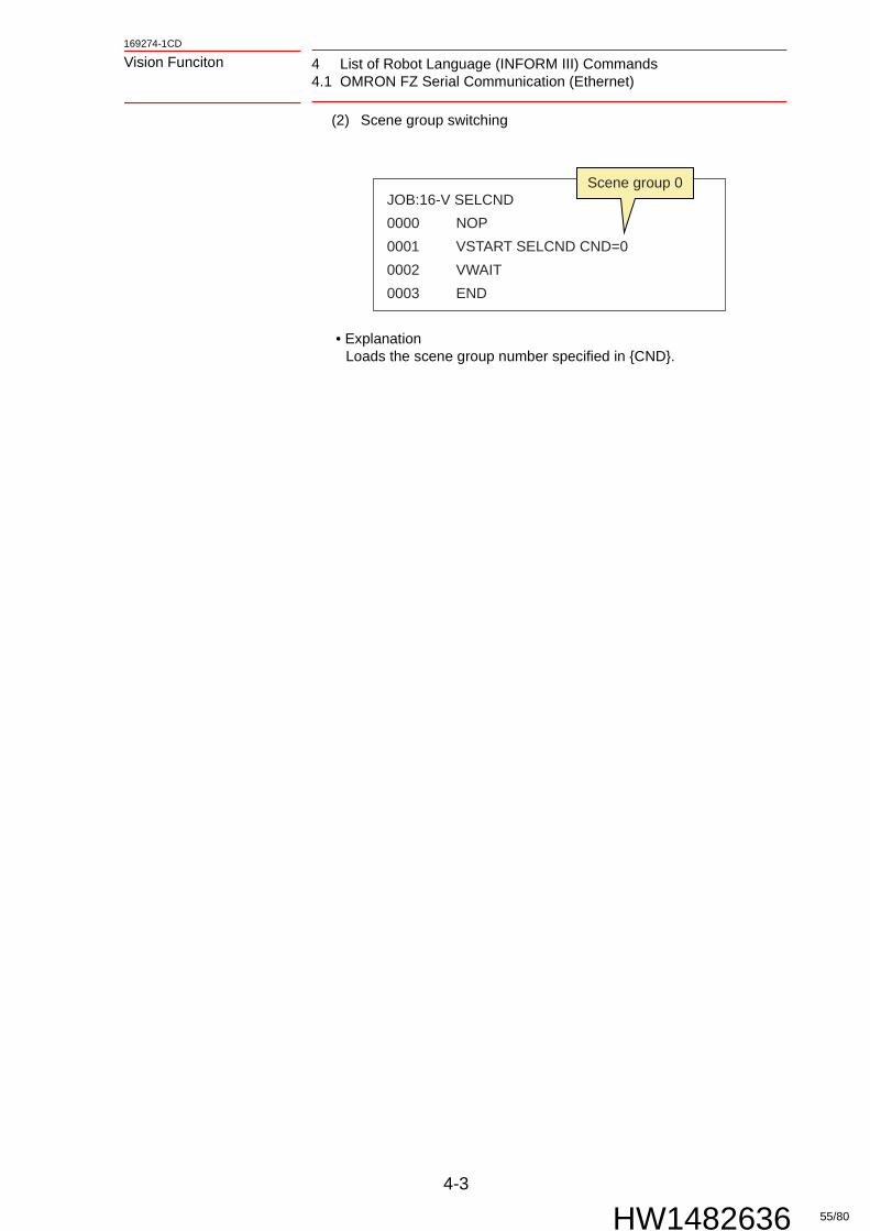
(2) Scene group switching
• ExplanationLoads the scene group number specified in {CND}.
JOB:16-V SELCND0000 NOP0001 VSTART SELCND CND=00002 VWAIT0003 END
Scene group 0
55/80

4 List of Robot Language (INFORM III) Commands4.2 COGNEX In-Sight Telnet (Ethernet)
4-4
169274-1CD
HW1482636
Vision Funciton
4.2 COGNEX In-Sight Telnet (Ethernet)
4.2.1 Usage example
(1) Acquire image → acquire data
• ExplanationAcquires the image with the currently open camera job. Then, the first vision file {VARIABLE FOR RESULT} B, I, R, and P variable data is stored.
Function designation
Additional parameters Function
FIND FT:Detection type number
MD:1)
Detection model number
VF# ():Vision file number
0 to 255 0 1 to 32 After switching to the {FT} camera job number, the image and detection results are acquired.2)
* Maximum 10 individual detection results
* 3) 1 1 to 32 Acquire image and detection results 2)
* Maximum 10 individual detection results
* 3) 4 1 to 32 Acquire the open camera job number
* 3) 5 1 to 32 Acquire the camera's online status
* 3) 6 1 to 32 Switch the camera to be online
* 3) 7 1 to 32 Only acquire detection results 2)
* Maximum 10 individual detection results
SELCND CND: Detection scene number
0 to 255 Switch to the {CND} camera job number
CALIB CALF# (): Calibration file number
1 to 16 {CALF#} data is used to perform camera calibration
1 Do not set the parameter No. between 2 and 3.2 Be sure to execute only after loading the proprietary camera job.3 It is possible to execute with any values for disabled parameters not related to processing.
Variable Contents
B [0] Number of detections
I [0] Workpiece 0: Score
R [0] Workpiece 0: Rotation offset amount
P [0] (1): (X coordinate) Workpiece 0: X coordinate
P [0] (2): (Y coordinate) Workpiece 0: Y coordinate
··· ···
JOB:12-V FIND 10000 NOP0001 VSTART FIND FT=0 MD=1 VF#(1)0002 VWAIT0003 END Any value OK Applies to vision file 1
1: Image+data acquisition function
56/80

4-5
169274-1CD
HW1482636
Vision Funciton 4 List of Robot Language (INFORM III) Commands4.2 COGNEX In-Sight Telnet (Ethernet)
(2) Camera job switching
• ExplanationOpen In-Sight camera job 001
(3) Camera job switch → acquire image → acquire data
• ExplanationAcquires the image after In-Sight camera job 001 is opened. Then, the first vision file {VARIABLE FOR RESULT} B, I, R, and P variable data is stored.
SUPPLE-MENT
If perform calibration using an In-Sight camera job, switching the camera job may require several tens of seconds.
Variable Contents
B [0] Number of detections
I [0] Workpiece 0: Score
R [0] Workpiece 0: Rotation offset amount
P [0] (1): (X coordinate) Workpiece 0: X coordinate
P [0] (2): (Y coordinate) Workpiece 0: Y coordinate
··· ···
SUPPLE-MENT
If perform calibration using an In-Sight camera job, switching the camera job may require several tens of seconds.
JOB:12-V SELCND0000 NOP0001 VSTART SELCND CND=10002 VWAIT0003 END
Camera job 001
JOB:12-V FIND 00000 NOP0001 VSTART FIND FT=1 MD=0 VF#(1)0002 VWAIT0003 END Camera job 001
0: Job switch+acquire image+acquire data function
Applies to vision file 1
57/80

4 List of Robot Language (INFORM III) Commands4.2 COGNEX In-Sight Telnet (Ethernet)
4-6
169274-1CD
HW1482636
Vision Funciton
(4) Acquire job number
• ExplanationStores the currently opened camera job number. If the job name currently opened by In-Sight does not begin with a number, or the number is less than 0 or more than 256, alarm: WRONG EXECUTION OF VISION INST [7] occurs.
(5) Acquiring online status
• ExplanationStores the online status of a connected camera.
(6) Shift to online
• ExplanationShifts a connected camera to be online.
Variable Contents
B [0] Currently opened camera job number
Variable Contents
B [0] 0: Offline status1: Online status
JOB:12-V FIND 40000 NOP0001 VSTART FIND FT=0 MD=4 VF#(1)0002 VWAIT0003 END Any value OK
4: Acquire job number function
Applies to vision file 1
JOB:12-V FIND 50000 NOP0001 VSTART FIND FT=0 MD=5 VF#(1)0002 VWAIT0003 END Any value OK
5: Acquiring online status function
Applies to vision file 1
JOB:12-V FIND 60000 NOP0001 VSTART FIND FT=0 MD=6 VF#(1)0002 VWAIT0003 END Any value OK
6: Shift to online
Applies to vision file 1
58/80

4-7
169274-1CD
HW1482636
Vision Funciton 4 List of Robot Language (INFORM III) Commands4.2 COGNEX In-Sight Telnet (Ethernet)
(7) Acquire only data
• ExplanationStores the first vision file {VARIABLE FOR RESULT} B, I, R, and P variable data from the currently open camera job. Trigger refresh is not performed.
Variable Contents
B [0] Number of detections
I [0] Workpiece 0: Score
R [0] Workpiece 0: Rotation offset amount
P [0] (1): (X coordinate) Workpiece 0: X coordinate
P [0] (2): (Y coordinate) Workpiece 0: Y coordinate
··· ···
JOB:12-V FIND 70000 NOP0001 VSTART FIND FT=0 MD=1 VF#(1)0002 VWAIT0003 END Any value OK
7: Function to acquire only data
Applies to vision file 1
59/80

4 List of Robot Language (INFORM III) Commands4.3 KEYENCE CV Serial Communication (Ethernet)
4-8
169274-1CD
HW1482636
Vision Funciton
4.3 KEYENCE CV Serial Communication (Ethernet)
4.3.1 Usage example
(1) Acquire image → acquire data
• ExplanationAcquires the image with the currently open setting number. Then, the first vision file {VARIABLE FOR RESULT} B, I, R, and P variable data is stored.
Function designation
Additional parameters Function
FIND FT:Detection type number
MD:1)
Detection model number
VF# ():Vision file number
* 2) 0 1 to 32 Acquire image + output data* Maximum 1 individual detection results
0 to 127 3) 1 * 3) Switches the window No. to {FT}
* 3) 2 * 3) Switches to operation mode
* 3) 3 * 3) Switches to setting mode
SELCND CND: Setting No.
0 to 255 Switches the setting No. to {CND}
CALIB CALF# (): Calibration file number
1 to 16 {CALF#} data is used to perform camera calibration
1 Do not set the parameter No. between 4 and 7.2 It is possible to execute with any values for disabled parameters not related to processing.3 Do not set the parameter No. between127 and 255.
Variable Contents
B [0] Number of detections
I [0] Workpiece 0: Correlation value
R [0] Workpiece 0: Rotation offset amount
P [0] (1): (X coordinate) Workpiece 0: X coordinate
P [0] (2): (Y coordinate) Workpiece 0: Y coordinate
JOB:13-V FIND 00000 NOP0001 VSTART FIND FT=0 MD=0 VF#(1)0002 VWAIT0003 END Any value OK
0: Image+data acquisition function
Applies to vision file 1
60/80
4-9
169274-1CD
HW1482636
Vision Funciton 4 List of Robot Language (INFORM III) Commands4.3 KEYENCE CV Serial Communication (Ethernet)
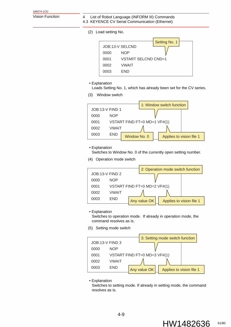
(2) Load setting No.
• ExplanationLoads Setting No. 1, which has already been set for the CV series.
(3) Window switch
• ExplanationSwitches to Window No. 0 of the currently open setting number.
(4) Operation mode switch
• ExplanationSwitches to operation mode. If already in operation mode, the command resolves as is.
(5) Setting mode switch
• ExplanationSwitches to setting mode. If already in setting mode, the command resolves as is.
JOB:13-V SELCND0000 NOP0001 VSTART SELCND CND=10002 VWAIT0003 END
Setting No. 1
JOB:13-V FIND 10000 NOP0001 VSTART FIND FT=0 MD=1 VF#(1)0002 VWAIT0003 END Window No. 0
1: Window switch function
Applies to vision file 1
JOB:13-V FIND 20000 NOP0001 VSTART FIND FT=0 MD=2 VF#(1)0002 VWAIT0003 END Any value OK
2: Operation mode switch function
Applies to vision file 1
JOB:13-V FIND 30000 NOP0001 VSTART FIND FT=0 MD=3 VF#(1)0002 VWAIT0003 END Any value OK
3: Setting mode switch function
Applies to vision file 1
61/80
4 List of Robot Language (INFORM III) Commands4.4 KEYENCE XG Serial Communication (Ethernet)
4-10
169274-1CD
HW1482636
Vision Funciton
4.4 KEYENCE XG Serial Communication (Ethernet)
4.4.1 Usage example
(1) Acquire image → acquire data
• ExplanationAcquires the image with the currently open inspection setting number. Then, the first vision file {VARIABLE FOR RESULT} B, I, R, and P variable data is stored.
Function designation
Additional parameters Function
FIND FT:Detection type number
MD:1)
Detection model number
VF# ():Vision file number
* 2) 0 1 to 32 Acquire image + output data* Maximum 20 individual detection results
0 to 1273) 1 * 3) Executes an {FT} custom command
* 3) 2 * 3) Switches to operation mode
* 3) 3 * 3) Switches to stop mode
SELCND CND: Detection scene number
0 to 255 Switches the inspection setting number to {CND}
CALIB CALF# (): Calibration file number
1 to 16 {CALF#} data is used to perform camera calibration
1 If executed using the parameter between 4 to 7, an alarm: WRONG EXECUTION OF VISION INST 11 will occur.2 It is possible to execute with any values for disabled parameters not related to processing.3 If executed using the parameter between 128 to 255, an alarm: WRONG EXECUTION OF VISION INST 11 will
occur.
Variable Contents
B [0] Number of detections
I [0] Workpiece 0: Correlation value
R [0] Workpiece 0: Rotation offset amount
P [0] (1): (X coordinate) Workpiece 0: X coordinate
P [0] (2): (Y coordinate) Workpiece 0: Y coordinate
··· ···
JOB:17-V FIND 00000 NOP0001 VSTART FIND FT=0 MD=0 VF#(1)0002 VWAIT0003 END Any value OK
0: Image+data acquisition function
Applies to vision file 1
62/80

4-11
169274-1CD
HW1482636
Vision Funciton 4 List of Robot Language (INFORM III) Commands4.4 KEYENCE XG Serial Communication (Ethernet)
(2) Load inspection testing No.
• ExplanationLoads inspection testing No. 1, which has already been set for the XG series.
(3) Custom command execution
• ExplanationExecutes the registered custom command No. 0.
(4) Operation mode switch
• ExplanationSwitches to operation mode. If already in operation mode, the command resolves as is.
(5) Stop mode switch
• ExplanationSwitches to stop mode. If already in stop mode, the command resolves as is.
NOTE It is possible to execute the command only. Do not set a command with a set return value.
JOB:V SELCND0000 NOP0001 VSTART SELCND CND=10002 VWAIT0003 END
Inspection testing No. 1
JOB:17-V FIND 10000 NOP0001 VSTART FIND FT=0 MD=1 VF#(1)0002 VWAIT0003 END Custom command No. 0
1: Custom command execution function
Applies to vision file 1
JOB:17-V FIND 20000 NOP0001 VSTART FIND FT=0 MD=2 VF#(1)0002 VWAIT0003 END Any value OK
2: Operation mode switch function
Applies to vision file 1
JOB:17-V FIND 30000 NOP0001 VSTART FIND FT=0 MD=3 VF#(1)0002 VWAIT0003 END Any value OK
3: Stop mode switch function
Applies to vision file 1
63/80

4 List of Robot Language (INFORM III) Commands4.5 SHARP IV-S200 Serial Communication (Ethernet)
4-12
169274-1CD
HW1482636
Vision Funciton
4.5 SHARP IV-S200 Serial Communication (Ethernet)
4.5.1 Usage example
(1) Acquire image → acquire data
• ExplanationAcquires the image with the currently open model type setting number. Then, the first vision file {VARIABLE FOR RESULT} B, I, R, and P variable data is stored.
Function designation
Additional parameters Function
FIND FT:1)
Detection type number
MD:2)
Detection model number
VF# ():Vision file number
0 0 to 3 1 to 32 Acquire image + output data from the {MD} trigger number* Maximum 18 individual detection results
SELCND CND: Detection scene number
0 to 255 Switches the inspection setting number to {CND}
CALIB CALF# (): Calibration file number
1 to 16 {CALF#} data is used to perform camera calibration
1 Do not set the parameter between 1 and 255.2 Do not set the parameter between 4 and 7.
Variable Contents
B [0] Number of detections
I [0] Workpiece 0: Correlation value
R [0] Workpiece 0: Rotation offset amount
P [0] (1): (X coordinate) Workpiece 0: X coordinate
P [0] (2): (Y coordinate) Workpiece 0: Y coordinate
··· ···
JOB:11-V FIND0000 NOP0001 VSTART FIND FT=0 MD=0 VF#(1)0002 VWAIT0003 END Trigger number 0
0: Image+data acquisition function
Applies to vision file 1
64/80

4-13
169274-1CD
HW1482636
Vision Funciton 4 List of Robot Language (INFORM III) Commands4.5 SHARP IV-S200 Serial Communication (Ethernet)
(2) Load part type setting No.
• ExplanationLoads part type setting No. 1.
NOTETo execute VSTART FIND - VWAIT following VSTART SELCND - VWAIT, be sure to insert a timer between VWAIT and VSTART. If there is no timer or the timer is too short, an alarm: WRONG EXECUTION OF VISION INST may occur.
JOB:11-V SELCND0000 NOP0001 VSTART SELCND CND=10002 VWAIT0003 END
Part type setting No. 1
65/80

5 Miscellaneous Functions5.1 Vision Condition Files
5-1
169274-1CD
HW1482636
Vision Funciton
5 Miscellaneous Functions
5.1 Vision Condition Files
This file sets the VSTART FIND detection conditions.
No. Name Explanation
COMMENT Comments can be added for the vision condition file.
COORDINATE Sets the detection result processing method.
{ROBOT} (default value) Uses the calibration data of the calibration file to convert detection results into robot coordinates and stores them as P variables. Be sure to use only after creating calibration data.
{PIXEL} The vision device detection results are stored as they are to P variables. This is set when performing vision device-side calibration, etc.
CALIB FILE NO. Specifies the calibration file number for when the coordinate system is {ROBOT}.
RESULT MAX NO. Sets the maximum number of data to store.
VARIABLE FOR RESULT Specifies the variable number for storing a detection result. Starting from the specified number, the number of results equal to that specified in {RESULT MAX NO.} is used. The maximum for {RESULT MAX NO.} is 10.
66/80
5-2
169274-1CD
HW1482636
Vision Funciton 5 Miscellaneous Functions5.2 Calibration File
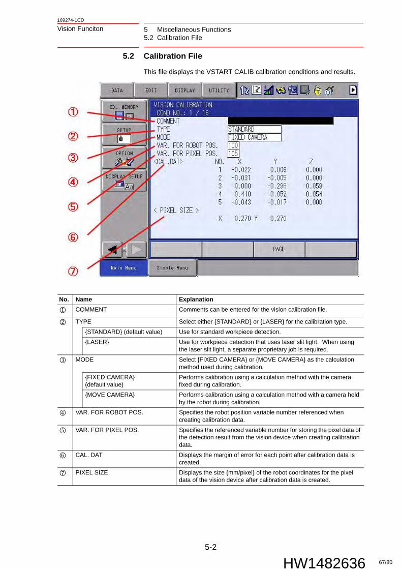
5.2 Calibration File
This file displays the VSTART CALIB calibration conditions and results.
No. Name Explanation
COMMENT Comments can be entered for the vision calibration file.
TYPE Select either {STANDARD} or {LASER} for the calibration type.
{STANDARD} (default value) Use for standard workpiece detection.
{LASER} Use for workpiece detection that uses laser slit light. When using the laser slit light, a separate proprietary job is required.
MODE Select {FIXED CAMERA} or {MOVE CAMERA} as the calculation method used during calibration.
{FIXED CAMERA} (default value)
Performs calibration using a calculation method with the camera fixed during calibration.
{MOVE CAMERA} Performs calibration using a calculation method with a camera held by the robot during calibration.
VAR. FOR ROBOT POS. Specifies the robot position variable number referenced when creating calibration data.
VAR. FOR PIXEL POS. Specifies the referenced variable number for storing the pixel data of the detection result from the vision device when creating calibration data.
CAL. DAT Displays the margin of error for each point after calibration data is created.
PIXEL SIZE Displays the size {mm/pixel} of the robot coordinates for the pixel data of the vision device after calibration data is created.
67/80

5 Miscellaneous Functions5.3 Loading and Saving Vision Files
5-3
169274-1CD
HW1482636
Vision Funciton
5.3 Loading and Saving Vision Files
Files used for vision functions can be saved to or loaded from external memory devices.
For details about using external memory devices, refer to the FS100 OPERATOR’S MANUAL.
5.3.1 Saving Files
1. Select {EX. MEMORY} from the top menu, and then select {SAVE}.
2. Select {FILE/GENERAL DATA}, add checks to the items {VISION} and {VISION CALIBRATION}, and then press [ENTER].
3. Select {YES} to save the data.
Data that can be saved File name after saving
Vision condition data VISION. CND
Vision calibration data VISCALIB. CND
68/80

5-4
169274-1CD
HW1482636
Vision Funciton 5 Miscellaneous Functions5.3 Loading and Saving Vision Files
5.3.2 Saving Files
1. Select {EX. MEMORY} from the top menu, and then select {LOAD}.
2. Select {FILE/GENERAL DATA}, add checks to the items {VISION} and {VISION CALIBRATION}, and then press [ENTER].
3. Select {YES} to load the data.
69/80

5 Miscellaneous Functions5.4 Alarm B Variable Output Function
5-5
169274-1CD
HW1482636
Vision Funciton
5.4 Alarm B Variable Output Function
If a communication error occurs, no alarm and resulting stop occurs, and instead a subcode of alarm 4124 "WRONG EXECUTION OF VISION INST" is written to the specified B variable. If a line is stopped due to a communication error alarm, in some cases a job can be created to perform communication retries, etc. to improve uptime efficiency.
The alarm B variable output function settings are determined by the following parameters.
Parameter Major item Minor item Remarks Default value
RS486 Vision communication error response function
Alarm storage B variable specification
0: Function disabledAlarm if a value outside of the range is specified
0
70/80

5-6
169274-1CD
HW1482636
Vision Funciton 5 Miscellaneous Functions5.4 Alarm B Variable Output Function
The values written to the VSTART execution result and B variable are as follows.
Communication status
When function disabled When function enabled
Normal Detection result stored Detection result stored+ B [RS486] = 0
Communication error occurred
Alarm 4124 WRONG EXECUTION OF VISION INST[5]
B [RS486] = 5
Alarm 4124 WRONG EXECUTION OF VISION INST [6]
B [RS486] = 6
Alarm 4124 WRONG EXECUTION OF VISION INST [7]
B [RS486] = 7
Miscellaneous Alarms
Includes sub-codes other than those described above Alarm 4124WRONG EXECUTION OF VISION INST [7]
Alarms shown to the left+ B [RS486] = 0
NOTE
• If this function is enabled, be sure to use a robot job to add communication error processing.
• If a B variable number is input that is outside of the defined system range for RS parameters, upon vision command execution the alarm: WRONG EXECUTION OF VISION INST [11] occurs.
71/80

5 Miscellaneous Functions5.4 Alarm B Variable Output Function
5-7
169274-1CD
HW1482636
Vision Funciton
5.4.1 Setting Procedure
1. In manager mode, set the B variable number of the alarm storage destination for the robot controller parameter {RS486}.
2. Add communication error processing to the robot job.
SUPPLE-MENT
An example for adding a process to retry during a communication error is shown below.
JOB: VFIND_RETRY
0000 NOP
0001 '-Setting-
0002 'maximum try num
0003 SET B088 3
0004 '
0005 '-Initialization-
0006 'try count
0007 SET B087 0
0008 '
0009 '-Detection
0010 *TRY
0011 INC B087
0012 'Stop if try num over
0013 JUMP *STOP IF B087>B088
0014 VSTART FIND FT=0 MD=0 VF#(1)
0015 VWAIT
0016 'Retry if communication err
0017 JUMP *TRY IF B089<>0
0018 *OK
0019 RET
0020 '
0021 *STOP
0022 PAUSE
0023 '-Communication err-
0024 END
72/80

5-8
169274-1CD
HW1482636
Vision Funciton 5 Miscellaneous Functions5.5 Communication Retry Function
5.5 Communication Retry Function
When a communication error occurs, the system software automatically retries communication. When there are line stops due to communication error alarms, enabling this function can reduce the alarm occurrence rate and improve uptime efficiency.
The alarm B variable output function settings are determined by the following parameters.
SUPPLE-MENT
Communication retry processing can also be created for the Section 5.4 “Alarm B Variable Output Function” on page 5-5.The main differences are as follows.• B variable output → It is possible to see the detailed status
such as the number of retries through job settings• Communication retry function → Only the retry function can
be set without changing existing jobs
NOTE
• If a large number of retry attempts is set, when a cable breaks, etc. there may be 5 minutes or more until the line stops. For systems where cable breakage is possible, the number of retries should be reduced, or Alarm B variable output function should be used for communication retries.
• If the retry timer value is close to 0 [ms] communication upon the execution of a retry may not be performed correctly. Set an appropriate value.
Parameter Major item Minor item Remarks Default value
RS487 Vision communication error response function
Communication retry number 0RS488 Communication retry sleep timer Units of 0.01 sec 0
73/80

5 Miscellaneous Functions5.6 Vision System IP Address Modification
5-9
169274-1CD
HW1482636
Vision Funciton
5.5.1 Setting Procedure
1. In manager mode, set robot controller parameter {RS487} to the number of communication retries, and {RS488} to the value for the retry timer.
5.6 Vision System IP Address Modification
The IP address used to communicate over Ethernet with the vision device can be freely set using RS parameters. If the RS parameter is not set, the vision device will use the default IP address settings to connect.
The IP address settings are determined by the following parameters.
Set the IP address within the private IP address range shown below.
Set an appropriate value for the subnet mask for the private IP address range that is used.
Parameter Major item Minor item Remarks Default value
RS460 Vision IP address IP address 1 Specify the xxx partEx.) xxx. 0. 0. 1
10
RS461 IP address 2 Ex.) 10. xxx. 0. 1 0
RS462 IP address 3 Ex.) 10. 0. xxx.1 0
RS463 IP address 4 Ex.) 10. 0. 0. xxx 100
IP address range Remarks
10. 0. 0. 1 - 10. 0. 0.254 Do not use the same address as the FS100 and PP.
IP address range subnet mask
10. 0. 0. 1 - 10. 0.255.254 255.255.0.0
10. 0. 0. 1 - 10. 0. 0.254 255.255.255.0
NOTE To change the robot controller's own IP address and subnet mask, contact your Yaskawa service representative.
SUPPLE-MENT
The default IP address settings for vision devices are as follows.
Communication method Default set IP address
OMRON FZ Serial Communication (Ethernet) 10. 0. 0. 10
COGNEX In-Sight Telnet (Ethernet) 10. 0. 0.210
KEYENCE CV Serial Communication (Ethernet) 10. 0. 0. 10
KEYENCE XG Serial Communication (Ethernet) 10. 0. 0. 10
SHARP IV-S200 Serial Communication (Ethernet) 10. 0. 0. 20
74/80

5-10
169274-1CD
HW1482636
Vision Funciton 5 Miscellaneous Functions5.7 Changing the Ethernet Communication Port Number of the Vision Device
5.6.1 Setting Procedure
1. Change the vision device's IP address. Check the respective manual for the operation method.
2. In manager mode, set the robot controller parameters {RS460-463} to the above IP address that was set.
5.7 Changing the Ethernet Communication Port Number of
the Vision Device
The communication port used to communicate over Ethernet with the vision device can be freely set using RS parameters. If the RS parameter is not set, the vision device will use the default communication port settings to connect.
The communication port number settings are determined by the following parameters.
5.7.1 Setting Procedure
1. Change the vision system port number. Refer to the maker's manuals for the operation procedure.
2. In manager mode, set the robot controller parameters {S4C0325} to the above port number that was set.
NOTE
• If "Alarm 4124: WRONG EXECUTION OF VISION INST [6]" occurs, check the parameter settings and the IP address values set for the vision device and the robot controller.
• If the above alarm continues to occur, change the IP address of either the vision device or the robot controller, and check their communication.
Parameter Major item Minor item Remarks Default value
S4C0325 Vision function Communication port number 0: Protocol default setting 0
SUPPLE-MENT
The default communication port number settings for vision devices are as follows.Communication method Default setting
communication port number
OMRON FZ Serial Communication (Ethernet) 9876COGNEX In-Sight Telnet (Ethernet) 23KEYENCE CV Serial Communication (Ethernet) 8500KEYENCE XG Serial Communication (Ethernet) 8500SHARP IV-S200 Serial Communication (Ethernet) 2001
NOTE
• If "Alarm 4124: WRONG EXECUTION OF VISION INST [6]" occurs, re-check the parameter and vision devices settings.
• If the above alarm continues to occur, change the port number and check their communication.
75/80

6 Alarm List
6-1
169274-1CD
HW1482636
Vision Funciton
6 Alarm List
Alarm Number
Message Meaning Cause Response
4124 WRONG EXECUTION OF VISION INST [1]
There is a mistake in the specified file's numbers.
Setting error
(1) Check the following settings.
• File number
WRONG EXECUTION OF VISION INST [2]
There is a mistake in the specified file's setting values.
Setting error
(1) Check the following settings.
• File setting values
WRONG EXECUTION OF VISION INST [3]
Calibration could not be executed.
Setting error
(1) Check the following settings.
• Robot coordinate values or pixel coordinate values used for calibration
• User variable numbers in the calibration file
Set the robot coordinate values or pixel coordinate values used for calibration to user variables.Correctly set the user variable numbers in the calibration file.
WRONG EXECUTION OF VISION INST [4]
The communication port for the vision system could not be initialized.
Setting error
(1) Check the following settings.
• Communication port parameters
WRONG EXECUTION OF VISION INST [5]
During data sending, a timeout occurred.
Setting error
(1) Check the following settings.
• Vision system communication settings
Connection error
(1) Reset the alarm.
(2) If the alarm occurs again, check the connection status of the following cables.
• Cable between the vision system and the controller
WRONG EXECUTION OF VISION INST [6]
During data receiving, a timeout occurred.
Setting error
(1) Check the following settings.
• Vision system communication settings
Connection error
(1) Reset the alarm.
(2) If the alarm occurs again, check the connection status of the following cables.
• Cable between the vision system and the controller
WRONG EXECUTION OF VISION INST [7]
There is a mistake in the data received by the vision system.
Setting error
(1) Check the following settings.
• Vision system communication settings
• Vision system detection settings
There is a mistake in the data received by the vision system.
Connection error
(1) Reset the alarm.
(2) If the alarm occurs again, check the connection status of the following cables.
• Cable between the vision system and the controller
76/80
6-2
169274-1CD
HW1482636
Vision Funciton 6 Alarm List
4124 WRONG EXECUTION OF VISION INST [8]
Pixel coordinate values could not be converted to robot coordinate values.
Setting error
(1) Check the following settings.
• Vision system communication settings
• The calibration file used
WRONG EXECUTION OF VISION INST [9]
Position-type variables (P variables) could not be loaded or saved.
Setting error
(1) Check the following settings.
• Specified position-type variable usage status.
Do not use the specified position-type variables with another job at the same time.
WRONG EXECUTION OF VISION INST [10]
Memory was insufficient and the attempt to secure a range of memory failed.
Operation error
(1) Reset the alarm, and execute the job again.
(2) If the alarm occurs again, save COMS.BIN in maintenance mode and contact your Yaskawa service representative with information of the machine status (operation procedures, etc.) at the time the error occurred.
WRONG EXECUTION OF VISION INST [11]
Measurement items (FT, MD, CND, RS parameters) setting error.
Setting error
Revise the measurement item setting values.
WRONG EXECUTION OF VISION INST [12]
Vision execution command data error.
Operation error
(1) Reset the alarm, and execute the job again.
Alarm Number
Message Meaning Cause Response
77/80

7 Parameter List
7-1
169274-1CD
HW1482636
Vision Funciton
7 Parameter List
Parameter Major item Minor item Remarks Default value
RS100 Individual VISION Function parameters
Data bit number 7: 7 bit8: 8 bit
8
RS101 Stop bit number 0: 1 bit1: 1.5 bit2: 2 bit
2
RS102 Parity specification 0: None 1: odd numbers2. even numbers
0
RS103 Transfer speed specification Baud rate7: 9600, 8: 19200
8
RS104 Response wait timer 1 (SELCND)
0.1 sec 100
RS105 Response wait timer 2 (FIND) 0.1 sec 20
RS106 Response wait timer 3 (FIND) 0.1 sec 100
RS107 Data resend retry number 3
RS108 Programming pendant VISION menu operation function
Data send interval 0.001 sec 100
RS109 Individual VISION Function parameters
Protocol type 5: OMRON RS232-C11: SHARP IV-S12: COGNEX13: KEYENCE CV16: OMRON Ethernet17: KEYENCE XG
-
RS460 Vision IP address IP address 1 Specify the xxx partEx.) xxx. 0. 0. 1
10
RS461 IP address 2 Ex.) 10. xxx. 0. 1 0
RS462 IP address 3 Ex.) 10. 0. xxx.1 0
RS463 IP address 4 Ex.) 10. 0. 0. xxx 100
RS486 Vision communication error response function
Alarm storage B variable specification
0: Function disabledAlarm if a value outside of the range is specified
0
RS487 Communication retry number 0
RS488 Communication retry sleep timer
0.01 sec 0
S4C0325 Vision function Communication port number 0: Protocol default setting 0
78/80

8-1
169274-1CD
HW1482636
Vision Funciton 8 Revision History
8 Revision History
Date CEN / ECN
Revision No.
Reason For Revision Initials
3/26/2014 46920 0 Original Release JFC
79/80

0HW1482636MANUAL NO.
Specifications are subject to change without noticefor ongoing product modifications and improvements.
FS100 OPTIONSINSTRUCTIONSFOR VISION FUNCTION
80/80


![Alternateur - Alternator - EUROREPAR...TOYOTA Avensis (T22) 1998ccm 1AC-FTV 1638109180 TOYOTA Corolla (_E11_)[1CD-FTV] 1638109180 TOYOTA Corolla (_E11_)[1CD-FTV] 1638109180 VOLVO S60](https://static.fdocuments.in/doc/165x107/5e8d8bc24f3a5f478d7422a1/alternateur-alternator-eurorepar-toyota-avensis-t22-1998ccm-1ac-ftv-1638109180.jpg)