For ViaSat-Harris Small Tactical Terminal (STT) … · 2018-09-27 · For ViaSat-Harris Small...
2
Support Equipment For ViaSat-Harris Small Tactical Terminal (STT) STT CONTROL AND INTERFACE UNIT (CIU) The STT Control and Interface Unit (CIU) provides everything needed to operate the ViaSat/Harris Small Tactical Terminal (STT). » All interconnect cables » Integrated power supply with Master Power On/Off » Integrated Fan Tray » Integrated Keypad/Display Unit (KDU) switchable between Channel 1 and Channel 2 » Indicators for Channel 1 Fail, Channel 2 Fail, and Link 16 Fail » Access to Host interfaces » Access to Voice interfaces » Link 16 Discretes: Zeroize, Long Term Transmit Inhibit (LTTI), and IFF Emergency » Access to Link 16 transmit signals and suppression discretes (both differential and single-ended) » Conversion of GPS ETR 5V, 10V to Differential Signal as required by STT ViaSat has a turnkey solution for employing the ViaSat-Harris Small Tactical Terminal (STT) in a ground or lab environment! The STT implements UHF, VHF and Link 16. The Control and Interface Unit (CIU) is a rack mountable enclosure providing all power, cooling, cabling, and control functions needed to operate the STT. Insert the terminal directly into the integrated Fan Tray and lock it in place with ARINC fasteners. Connect the cables provided to the front of the STT and the rear panel of the CIU, routing them through the cable tray below the front panel. Turn the master Power ON/ OFF switch on the rear of the unit and you’re ready to begin operations! The master ON/OFF switch provides 28V DC power to the STT and all components of the CIU. A Power On Indicator illuminates when power is applied. Separate On/Off switches control each channel. FRONT PANEL CONTROLS AND INTERFACES The Harris Keyboard/Display Unit (KDU) mounts on the front panel and provides operator control functions for Channel 1 (UHF/VHF or Link 16) and Channel 2 (UHF/VHF) based on a selector switch. Separate power on indicators are provided for each channel. A Link 16 Fail indicator indicates the health of the Link 16 capability. The front panel provides connectors for each channel’s interfaces: » Ethernet Host (RJ45) » USB (B) » DTE Waveform (DB 25) » Red Console (DB 9) » Zeroize In addition there are switches for the Channel 1 Link 16 discretes: » LTTI » IFF Emergency REAR PANEL CONNECTIONS The rear panel provides an EMI-filtered AC Power Input for the embedded 28V power supplies, an input connector for the 1 Pulse Per Second External Time Reference and a 28 VDC Aux Input for external power. Also accessible on the rear panel are maintenance ports and BNC connectors for the differential Link 16 discretes: » Message Transmit (output pulse) » Pulse Transmit (output pulse) » Receiver Suppression (input pulse) STT Control and Interface Unit PN: 1115296 STT Not Included Front Rear » IPF Monitor Suppression (input pulse) » Transmit Suppression (input pulse) CIU CABLES The following CIU cables interface the CIU to the STT: » STT Channel 1 Host Port (W1) » STT Channel 2 Host Port (W2) » STT Discretes (W3) » STT Channel 1 Audio and Keyfill (W4) » STT Channel 2 Audio and Keyfill (W10) » STT 28V Power (W5) The following cables are also included with the unit: » 1132441 STT Link 16 RF Cable Set for Antenna A and B (W8 and W9) » 1143746 Voice Relay Cable (12” cable connecting W4 and W10) SPECIFICATIONS » Height 10.5 inches (6U) » Front Panel Width 19 inches » Box Width 17 inches » Depth 17 inches » Weight (approximate) 18 lbs. » Electrical Input Power 100-264 VAC, 47-63 Hz, 315 W (Max)
Transcript of For ViaSat-Harris Small Tactical Terminal (STT) … · 2018-09-27 · For ViaSat-Harris Small...

Support EquipmentFor ViaSat-Harris Small Tactical Terminal (STT)
STT CONTROL AND INTERFACE UNIT (CIU)The STT Control and Interface Unit (CIU) provides everything needed to operate the ViaSat/Harris Small Tactical Terminal (STT).
» All interconnect cables
» Integrated power supply with Master Power On/Off
» Integrated Fan Tray
» Integrated Keypad/Display Unit (KDU) switchable between Channel 1 and Channel 2
» Indicators for Channel 1 Fail, Channel 2 Fail, and Link 16 Fail
» Access to Host interfaces
» Access to Voice interfaces
» Link 16 Discretes: Zeroize, Long Term Transmit Inhibit (LTTI), and IFF Emergency
» Access to Link 16 transmit signals and suppression discretes (both differential and single-ended)
» Conversion of GPS ETR 5V, 10V to Differential Signal as required by STT
ViaSat has a turnkey solution for employing the ViaSat-Harris Small Tactical Terminal (STT) in a ground or lab environment! The STT implements UHF, VHF and Link 16. The Control and Interface Unit (CIU) is a rack mountable enclosure providing all power, cooling, cabling, and control functions needed to operate the STT. Insert the terminal directly into the integrated Fan Tray and lock it in place with ARINC fasteners. Connect the cables provided to the front of the STT and the rear panel of the CIU, routing them through the cable tray below the front panel. Turn the master Power ON/OFF switch on the rear of the unit and you’re ready to begin operations! The master ON/OFF switch provides 28V DC power to the STT and all components of the CIU. A Power On Indicator illuminates when power is applied. Separate On/Off switches control each channel.
FRONT PANEL CONTROLS AND INTERFACESThe Harris Keyboard/Display Unit (KDU) mounts on the front panel and provides operator control functions for Channel 1 (UHF/VHF or Link 16) and Channel 2 (UHF/VHF) based on a selector switch. Separate power on indicators are provided for each channel. A Link 16 Fail indicator indicates the health of the Link 16 capability. The front panel provides connectors for each channel’s interfaces: » Ethernet Host (RJ45) » USB (B) » DTE Waveform (DB 25) » Red Console (DB 9) » Zeroize
In addition there are switches for the Channel 1 Link 16 discretes: » LTTI » IFF Emergency
REAR PANEL CONNECTIONSThe rear panel provides an EMI-filtered AC Power Input for the embedded 28V power supplies, an input connector for the 1 Pulse Per Second External Time Reference and a 28 VDC Aux Input for external power. Also accessible on the rear panel are maintenance ports and BNC connectors for the differential Link 16 discretes: » Message Transmit (output pulse) » Pulse Transmit (output pulse) » Receiver Suppression (input pulse)
STT Control and Interface UnitPN: 1115296
STT Not IncludedFront Rear
» IPF Monitor Suppression (input pulse) » Transmit Suppression (input pulse)
CIU CABLESThe following CIU cables interface the CIU to the STT: » STT Channel 1 Host Port (W1) » STT Channel 2 Host Port (W2) » STT Discretes (W3) » STT Channel 1 Audio and Keyfill (W4) » STT Channel 2 Audio and Keyfill (W10) » STT 28V Power (W5)
The following cables are also included with the unit: » 1132441 STT Link 16 RF Cable Set for Antenna A and B (W8 and W9) » 1143746 Voice Relay Cable (12” cable connecting W4 and W10)
SPECIFICATIONS » Height 10.5 inches (6U) » Front Panel Width 19 inches » Box Width 17 inches » Depth 17 inches » Weight (approximate) 18 lbs. » Electrical Input Power 100-264 VAC, 47-63 Hz, 315 W (Max)
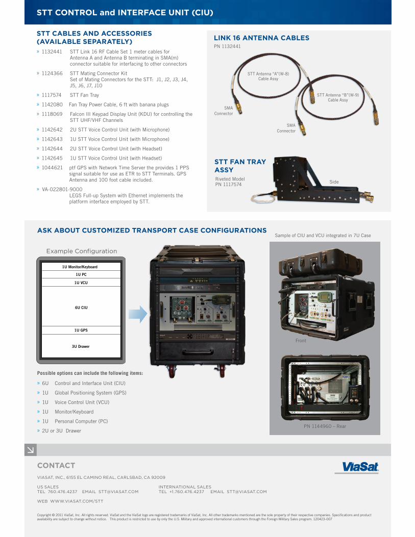
ASK ABOUT CUSTOMIZED TRANSPORT CASE CONFIGURATIONS
STT CONTROL and INTERFACE UNIT (CIU)
CONTACT VIASAT, INC., 6155 EL CAMINO REAL, CARLSBAD, CA 92009
US SALES INTERNATIONAL SALESTEL 760.476.4237 EMAIL [email protected] TEL +1.760.476.4237 EMAIL [email protected] WEB WWW.VIASAT.COM/STT
Copyright © 2011 ViaSat, Inc. All rights reserved. ViaSat and the ViaSat logo are registered trademarks of ViaSat, Inc. All other trademarks mentioned are the sole property of their respective companies. Specifications and product availability are subject to change without notice. This product is restricted to use by only the U.S. Military and approved international customers through the Foreign Military Sales program. 120423-007
STT CABLES AND ACCESSORIES (AVAILABLE SEPARATELY) » 1132441 STT Link 16 RF Cable Set 1 meter cables for Antenna A and Antenna B terminating in SMA(m) connector suitable for interfacing to other connectors
» 1124366 STT Mating Connector Kit Set of Mating Connectors for the STT: J1, J2, J3, J4, J5, J6, J7, J10
» 1117574 STT Fan Tray
» 1142080 Fan Tray Power Cable, 6 ft with banana plugs
» 1118069 Falcon III Keypad Display Unit (KDU) for controlling the STT UHF/VHF Channels
» 1142642 2U STT Voice Control Unit (with Microphone)
» 1142643 1U STT Voice Control Unit (with Microphone)
» 1142644 2U STT Voice Control Unit (with Headset)
» 1142645 1U STT Voice Control Unit (with Headset)
» 1044621 ptf GPS with Network Time Server the provides 1 PPS signal suitable for use as ETR to STT Terminals. GPS Antenna and 100 foot cable included.
» VA-022801-9000 LEGS Full-up System with Ethernet implements the platform interface employed by STT.
SideRiveted Model PN 1117574
STT Antenna “B”(W-9) Cable Assy
STT Antenna “A”(W-8) Cable Assy
SMAConnector
SMAConnector
STT FAN TRAY ASSY
LINK 16 ANTENNA CABLES
Sample of CIU and VCU integrated in 7U Case
1U Monitor/Keyboard
1U PC
1U VCU
6U CIU
1U GPS
3U Drawer
Example Configuration
Possible options can include the following items:
» 6U Control and Interface Unit (CIU)
» 1U Global Positioning System (GPS)
» 1U Voice Control Unit (VCU)
» 1U Monitor/Keyboard
» 1U Personal Computer (PC)
» 2U or 3U Drawer
Front
PN 1144960 – Rear
PN 1132441