for the SenTec Digital Monitoring System · ii Figures Figure 1 Front Panel of the SDM 6 Figure 2...
59
for the SenTec Digital Monitoring System (Software Version SMB V06.20; MPB V04.04)
Transcript of for the SenTec Digital Monitoring System · ii Figures Figure 1 Front Panel of the SDM 6 Figure 2...

for the SenTec Digital Monitoring System (Software Version SMB V06.20; MPB V04.04)

SenTec AG, Ringstrasse 39, CH-4106 Therwil, Switzerland, www.sentec.ch
HB-005615-d
Warranty The manufacturer warrants to the initial purchaser that each new component of the SenTec Digital Monitoring System (see list of components) will be free from defects in workmanship and materials. The manufacturer‘s sole obligation under this warranty is to replace any component – for which the manufacturer acknowledges the warranty cover - with a replacement component. Warranty Exclusions SenTec AG can neither guarantee or verify instrument performance characteristics nor accept warranty claims or product liability claims if the recommended procedures are not carried out, if the product has been subject to misuse, neglect or accident, if the product has been damaged by extraneous causes, if accessories other than those recommended by SenTec AG are used, or if instrument repairs are not carried out by SenTec authorized service personnel. CAUTION: Federal law (U.S.) restricts this device to sale by or on the order of a physician. Patents/Trademarks/Copyright International Industrial Design No. DM/054179, Japanese Design No. 1137696, U.S. Patent No. D483488, U.S. Patent No. 6760610, European Patent No. 1335666 / SenTec™, V-Sign™ and V-STATS™ are trademarks of SenTec AG / © 2007 SenTec AG. All rights reserved. The contents of this document may not be reproduced in any form or communicated to any third party without the prior written consent of SenTec AG. While every effort is made to ensure the correctness of the information provided in this document, SenTec AG assumes no responsibility for errors or omissions. This document is subject to change without notice.
Patient Monitor WITH RESPECT TO ELECTRICAL SHOCK, FIRE AND MECHANICAL HAZARDS ONLY IN ACCORDANCE WITH UL 60601-1/CAN/CSA C22.2 No. 601.1, IEC 60601-1-4, IEC 60601-2-23
20LW

Contents
SenTec Digital Monitoring System i
Contents Contents i Figures ii Tables ii Abbreviations ii
1 INTRODUCTION 1 1.1 Related Documents 1 1.2 Safety Information 1
2 THE SENTEC DIGITAL MONITORING SYSTEM (SDMS) 5 2.1 Components 5 2.2 The SenTec Digital Monitor (SDM) 6
3 MAINTENANCE/SAFETY & FUNCTIONALITY TESTS 8 3.1 V-Sign™ Sensor 9 3.2 SenTec Digital Monitor 11 3.3 Docking Station 21 3.4 Digital Monitor Extension Cable 21
4 TROUBLESHOOTING 22 4.1 How to use the troubleshooting list 22 4.2 Troubleshooting List 24
5 REPAIRS 33 5.1 Prior to Repair 35 5.2 Cleaning the sensor without membrane 35 5.3 Replacement, Tip-up Foot 36 5.4 Replacement, Silicon Foot 36 5.5 Replacement, main fuses 37 5.6 Replacement, Docking Station Door 37 5.7 Replacement, Docking Station Gasket 38 5.8 Breaking up the V-Sign™ Disposable Set 40 5.9 Firmware Updates 40 5.10 Instructions for Shipment 41 5.11 Accessories and Spare Parts 42
6 DISPOSAL 44 6.1 SenTec Digital Monitor 44 6.2 Cables 44 6.3 V-SignTM Sensor 44 6.4 Service Gas Bottle 44 6.5 Consumables 44
7 APPENDIX 45 7.1 Pin Assignment 45 7.2 Technical Specifications 48 7.3 Contact 48 7.4 Protocol for Safety Related Test 49 7.5 Order Form for Service Technician 52 7.6 Repair Form 53 7.7 Repair Reporting Form 54 7.8 Certificate of Disinfection 55

ii
Figures Figure 1 Front Panel of the SDM 6 Figure 2 Rear Panel of the SDM 7 Figure 3 Connections for the Safety Test 18 Figure 4 Connections for the High Potential Test, AP 19 Figure 5 Connections for the High Potential Test, PC 20 Figure 6 Removal of the Membrane from the Sensor 35 Figure 7 Replacement, Tip-up Foot 36 Figure 8 Replacement, Silicon Foot 36 Figure 9 Replacement, Main Fuses 37 Figure 10 Docking Station Door Insertion 38 Figure 11 Replacement, Docking Station Gasket 39 Figure 12 Positioning of the Docking Station Gasket 39 Figure 13 Breaking up the V-Sign™ Disposable Set 40 Figure 14 Packing in the Original Box 41 Figure 15 Sensor Connection Port 45 Figure 16 Serial Data Port (RS-232) 46 Figure 17 Multipurpose I/O Port 46
Tables Table 1 Related Documents 1 Table 2 Connections for the High Potential Test, AP 19 Table 3 Connections for the High Potential Test, PC 20 Table 4 Example of a Troubleshooting Procedure 23 Table 5 Troubleshooting PCO2 Monitoring 25 Table 6 Troubleshooting SpO2 and PR Monitoring 25 Table 7 Sensor specific troubleshooting 27 Table 8 Sensor Application specific troubleshooting 28 Table 9 SDM specific troubleshooting 30 Table 10 Docking Station specific troubleshooting 32 Table 11 Accessories and Spare Parts List 43 Table 12 Pin Assignment, Sensor Connection Port 45 Table 13 Pin Assignment, Serial Data Port (RS-232) 46 Table 14 Pin Assignment, Multipurpose I/O Port 47
Abbreviations CO2 Carbon dioxide DS Docking Station O2 Oxygen PaCO2 Arterial carbon dioxide partial pressure PCB Printed circuit board PcCO2 Cutaneous carbon dioxide partial pressure PCO2 PaCO2 calculated from the measured PcCO2 (cutaneous blood gas measurement) POST Power-On Self-Test PR Pulse rate SaO2 Arterial oxygen saturation SDM SenTec Digital Monitor SDMS SenTec Digital Monitoring System SpO2 Functional oxygen saturation of arterial hemoglobin (pulse oximeter measurement)

1 Introduction
SenTec Digital Monitoring System 1
1 Introduction This Manual is intended to provide information on the service and repair of the SenTec Digital Monitoring System (SDMS). The SenTec Digital Monitoring System consists of the Sentec Digital Monitor (SDM), the V-Sign™ Sensor and accessories. This Manual is to be used by qualified service personnel only. The service personnel should read this Manual carefully before performing any service or repairs. In particular the section 1.2, "Safety Information" must be read and understood.
This Manual contains confidential information. The contents of this document may not be reproduced in any form or communicated to any third party without the prior written consent of SenTec AG.
1.1 Related Documents To perform service or repairs you must know how to operate the SDMS. Refer to the following Manuals and Directions for Use:
System component Manual Content
SenTec Digital Monitoring System Instruction Manual for the SDMS Getting started / Using the SDMS
Sentec Digital Monitor Technical Manual for the SDM Detailed information on the SDM
Sentec Digital Monitoring System Service Manual for the SDMS
Provides information on repair and service procedures that do not require to open the cover of the SDMS
Sentec Digital Monitoring System
Repair and Service Manual for the SDMS
Provides information on repair and service procedures of the SDMS
Table 1 Related Documents
1.2 Safety Information
Warnings
This symbol identifies a WARNING statement. Warning statements refer to conditions that may lead to risk or injury to the patient or user.
Cautions
This symbol identifies a CAUTION statement. Caution statements refer to conditions that may lead to damage or malfunction of the equipment.
Carefully read all safety information in this Manual and in the Technical Manual for the SDM before operating the device or performing service/repairs.

1 Introduction
2
1.2.1 General Safety Information
WARNING: Explosion hazard. Do not use the SDM in the presence of flammable anesthetics/gases or in any environment which has increased oxygen content.
WARNING: The SDM must be connected to a grounded (3-wire) AC power outlet. Ensure that power and protective ground lines are connected correctly.
WARNING: For US, respectively Japan: Grounding reliability can only be achieved when the SDM is connected to an equivalent receptacle marked HG (Hospital Grade), respectively HGJ (Hospital Grade Japan).
WARNING: To ensure protection of patient, operator and equipment from the effects of defibrillation and diathermy/electro surgery, cables manufactured by SenTec AG must be used.
WARNING: Equipment is protected against electrostatic discharge. The display may be temporarily affected during discharge to chassis ground, but will rapidly recover.
WARNING: This device has been tested and found to comply with the requirements for medical devices according to the IEC 60601-1-2 (second edition), and the Medical Device Directive 93/42/EEC. These requirements are designed to provide reasonable protection against harmful interference in a typical medical installation.
WARNING: Certain types of mobile telecommunication equipment could potentially interfere with SDM operation. Mobile telecommunication equipment should not be used within five meters (16,4 feet) of the SDM.
WARNING: Keep the SDM (as well as any discarded parts) out of reach of children under the age of 5 years. Some parts of the SDM are small enough to be swallowed and may block the trachea.

1 Introduction
SenTec Digital Monitoring System 3
WARNING: Do not spray, pour, or spill any liquid on the SDM, its accessories, connectors, switches, or openings in the chassis.
WARNING: If the SDM has been wetted accidentally it must be wiped dry externally, allowed to dry thoroughly, and be inspected by qualified service personnel before further use.
WARNING: If connecting the SDM to any other equipment, verify proper operation before clinical use. Both the SDM and the equipment connected to it must be connected to a properly grounded AC power outlet. Combinations of equipments must be in compliance with IEC/UL 60601-1 systems requirements. Anyone who configures a medical system by connecting additional equipment to the SDM is responsible for ensuring that the resulting system complies with the requirements of IEC 60601-1-1 and IEC 60601-1-2.
WARNING: During normal operation (except transport), it is recommended that the monitor is always connected to the AC power outlet.
WARNING:
To maintain monitor readiness:
1. ALWAYS clean the sensor before putting it into the Docking Station!
2. ALWAYS store the clean sensor in the Docking Station after monitoring!
3. ALWAYS keep the monitor switched on!
CAUTION: Do not immerse the SDMS or the connectors of any connecting cables in liquid solution.
CAUTION: Do not sterilize any parts of the SDMS by irradiation, steam or ethylene oxide.
1 Introduction
4
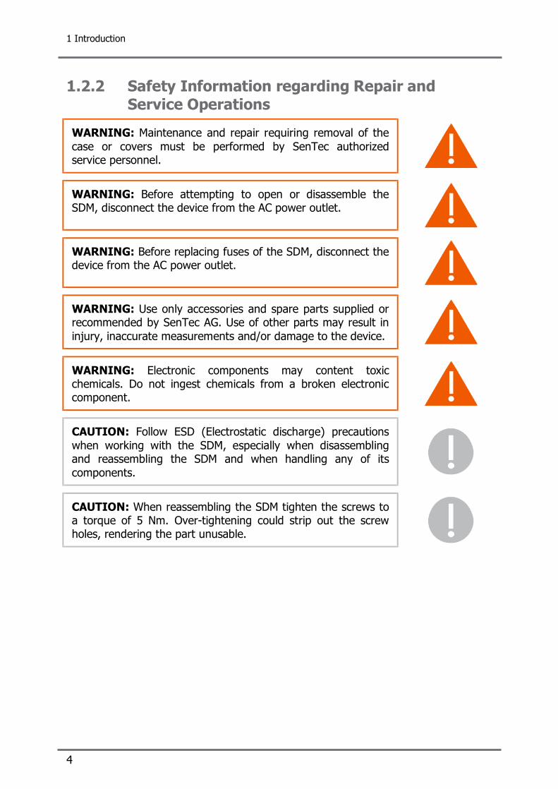
1.2.2 Safety Information regarding Repair and Service Operations
WARNING: Maintenance and repair requiring removal of the case or covers must be performed by SenTec authorized service personnel.
WARNING: Before attempting to open or disassemble the SDM, disconnect the device from the AC power outlet.
WARNING: Before replacing fuses of the SDM, disconnect the device from the AC power outlet.
WARNING: Use only accessories and spare parts supplied or recommended by SenTec AG. Use of other parts may result in injury, inaccurate measurements and/or damage to the device.
WARNING: Electronic components may content toxic chemicals. Do not ingest chemicals from a broken electronic component.
CAUTION: Follow ESD (Electrostatic discharge) precautions when working with the SDM, especially when disassembling and reassembling the SDM and when handling any of its components.
CAUTION: When reassembling the SDM tighten the screws to a torque of 5 Nm. Over-tightening could strip out the screw holes, rendering the part unusable.

2 The SenTec Digital Monitoring System (SDMS)
SenTec Digital Monitoring System 5
2 The SenTec Digital Monitoring System (SDMS)
2.1 Components The SDMS consists of the following components, accessories and disposables:
SenTec Digital Monitor (REF: SDM) V-Sign™ Sensor (REF: VS-A/P) V-Sign™ Disposable Set (REF: VS-DSET) Ear Clip (REF: EC-A/P) Multi-Site Attachment Rings for Adults, Pediatrics, Neonates (REF: MAR-A/P/N) Multi-Site Attachment Rings for Adults, Pediatrics (REF: MAR-A/P) Digital Monitor Extension Cable (REF: AC-150) Sensor Gel (REF: Gel-04) Service Gas (REF: Gas-0812) Mains Power Cord V-STATS installation CD (REF: V-STATS) Instruction Manual for SDMS (REF: IM-xx) User Manual CD (REF: UMCD) Quick Reference Guide (REF: QRG-xx)

2 The SenTec Digital Monitoring System (SDMS)
6
2.2 The SenTec Digital Monitor (SDM)
2.2.1 Front Panel
1 Trend Display Area 2 Numerical Display Area 3 Select Button 4 Alarm Mute Button 5 Alarm Mute Indicator (yellow LED) 6 Door Lock 7 Docking Station Door 8 Enter Button 9 Display Button 10 AC Power/Battery Indicator (green/yellow LED) 11 UP/DOWN Buttons 12 ON/OFF Indicator (green LED) 13 Status Bar 14 Speaker (on the side panel)
Figure 1 Front Panel of the SDM

2 The SenTec Digital Monitoring System (SDMS)
SenTec Digital Monitoring System 7
2.2.2 Rear Panel
15 Sensor Connection Port 16 Multipurpose I/O-Port (Nurse call, analog output) 17 Serial Data Port (RS-232) 18 Network Port (LAN) * 19 Gas Bottle Slot 20 Fan 21 Equipotential Terminal Connector (ground) 22 Fuse Holder 23 AC Power Connector 24 ON/OFF Switch
* feature not currently available
Figure 2 Rear Panel of the SDM

3 Maintenance/Safety & Functionality Tests
8
3 Maintenance/Safety & Functionality Tests
To guarantee continuous performance, safety, and reliability of the equipment maintenance procedures and checks have to be performed regularly. The maintenance of the SDMS is subdivided into "Cleaning and Disinfection", "Routine Checks" and "Safety & Functionality Tests".
Note: Prior to maintenance, service or repairs all components of the SDMS must be cleaned and disinfected. If equipment is send to service personnel, a local SenTec representative or to SenTec AG a completed "Certificate of Disinfection" (see page 55) must be attached.
"Cleaning and disinfection" procedures are described in the "Technical Manual for the SDM" and in the "Directions for use of the V-SignTM Sensor".
"Routine Checks" that can be performed by the user are described in the "Instruction Manual for the SDMS" and in the "Technical Manual for the SDM".
The "Safety and functionality tests" specified in the present paragraph must be performed annually by qualified service personnel. If any of the tests specified below fails, the respective problem must be fixed before the equipment is returned to the user.
Note: To perform a complete "Safety & functionality test" all tests described in this chapter MUST be performed.
Note: Use the Protocol "Safety Related Test" (see 7.4 "Protocol for Safety Related Test", page 49) to guide you through the complete "Safety & Functionality test" and to document your test results. The system MUST pass all tests mentioned in this protocol.
Note: If any of the tests specified below fails, the respective problem must be fixed before the equipment is returned to the user.

3 Maintenance/Safety & Functionality Tests
SenTec Digital Monitoring System 9
3.1 V-Sign™ Sensor
3.1.1 Visual Inspection Visually inspect the membrane of the sensor. If you suspect a damage of the membrane, exchange the membrane of the sensor. Visually inspect the sensor body for damages. Check the sensor cable for breaks or damages of the isolation. Check the sensor cable plug and its connectors for damages.
If any of the components of the sensor is irreversibly damaged, replace the sensor with a new V-Sign™ Sensor.
3.1.2 Labeling Check presence/legibility of the serial number (label on the plug of the sensor cable).
If the serial number can not be found or read, read the serial number of the V-Sign™ Sensor out of the SDM (sub-menu "System Information") and write it on the plug of the sensor cable.
3.1.3 Sensor LEDs Switch on the sensor and verify that the sensor emits red light. Then insert the sensor into the Docking Station and verify that the calibration display activates.
If these requirements are not fulfilled refer to section 4.2.3 "Sensor specific troubleshooting", page 26 to further evaluate the problem.

3 Maintenance/Safety & Functionality Tests
10
3.1.4 Function Test: SpO2 + PR Apply the sensor to the earlobe of a healthy person: Compare SpO2 and PR readings against the readings of a reference pulse oximeter (e.g. N595 with Durasensor 100 from Nellcor). The SpO2 and PR reading should be within ± 3%SpO2 and ± 3 bpm, respectively.
If these requirements are not fulfilled refer to section 4.2.3 "Sensor specific troubleshooting", page 26 to further evaluate the problem.
3.1.5 Function Test: PCO2 Calibrate the sensor and apply it to the ear of a healthy person: Verify, that the PCO2 readings equilibrate (stabilize) within 3 to 10 minutes and are within 33 to 47 mmHg after stabilization.
If this requirement is not fulfilled refer to section 4.2.1 "Troubleshooting PCO2 Monitoring", page 24 to further evaluate the problem.
For testing the PCO2 functionality sensor test equipment is available for SenTec authorized service personnel.
3.1.6 PCO2 Sensitivity Test Test the PCO2 sensitivity as follows:
1. Following a calibration, expose the sensor for approximately 3 minutes to ambient air.
2. Reinsert the sensor into the Docking Station. The first displayed PCO2 value should be at least 30 mmHg (4.0 kPa) lower than after calibration.
3. If this difference is not reached, exchange the membrane of the sensor and repeat the test.
4. If there is no improvement, clean the sensor following the instructions provided in section 5.2 "Cleaning the sensor without membrane", page 35 and repeat the test.
After a renewed missing of this difference, send the V-Sign™ Sensor to your local SenTec representative (refer to section 5.10 "Instructions for Shipment", page 41).
3.1.7 Sensor Temperature Surveillance Connect the sensor to the SDM and switch the monitor on. Immerse the sensor into water of 45°C – 50°C. Verify that the red sensor LED switches off, a low priority alarm starts to sound and that the message "Sensor fault" or "Temp. limiter active" displays.
If the test fails, send the V-Sign™ Sensor to your local SenTec representative (see section 5.10 "Instructions for Shipment", page 41).

3 Maintenance/Safety & Functionality Tests
SenTec Digital Monitoring System 11
3.2 SenTec Digital Monitor
3.2.1 Visual Inspection Visually check the entire SDMS for possible damages.
If you detect a damage, the SDM needs to be repaired according to section 5 "Repairs", page 33.
3.2.2 Labeling Check the SDM for presence and legibility of the following labels and symbols: Front panel: Symbols for buttons and LED’s (see Figure 1, page 6). Rear panel: Labels of all ports, connectors and switches; label with SN, REF and
, CE label, UL label and WEEE Disposable label (see Figure 2, page 7).
If the requirements for the front or rear panel are not fulfilled contact your local SenTec representative or send back the monitor according to section 5.10 "Instructions for Shipment", page 41.
3.2.3 POST After switching on, the SDM initiates a Power-On Self-Test (POST): Some components of the SDM are checked. The display, as well as the visual and audible indicators (i.e. LED’s and speaker) are shortly activated. The result of the POST is indicated by a ü (passed) or û (failed) symbol.
Note: The message "FLASH Memory Inside" is displayed on the POST screen, if the hardware version of your monitor supports a non-volatile FLASH memory.
If the POST fails, an error message shows up at the bottom of the POST screen, see section 4 "Troubleshooting", page 22. The SDM needs to be repaired according to section 5 " Repairs", page 33.
3 Maintenance/Safety & Functionality Tests
12
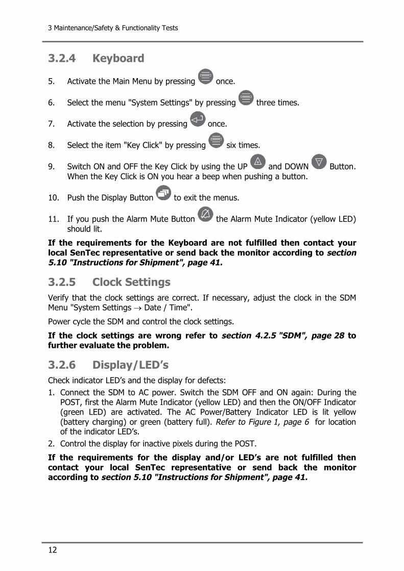
3.2.4 Keyboard
5. Activate the Main Menu by pressing once.
6. Select the menu "System Settings" by pressing three times.
7. Activate the selection by pressing once.
8. Select the item "Key Click" by pressing six times.
9. Switch ON and OFF the Key Click by using the UP and DOWN Button. When the Key Click is ON you hear a beep when pushing a button.
10. Push the Display Button to exit the menus.
11. If you push the Alarm Mute Button the Alarm Mute Indicator (yellow LED) should lit.
If the requirements for the Keyboard are not fulfilled then contact your local SenTec representative or send back the monitor according to section 5.10 "Instructions for Shipment", page 41.
3.2.5 Clock Settings Verify that the clock settings are correct. If necessary, adjust the clock in the SDM Menu "System Settings → Date / Time".
Power cycle the SDM and control the clock settings.
If the clock settings are wrong refer to section 4.2.5 "SDM", page 28 to further evaluate the problem.
3.2.6 Display/LED’s Check indicator LED’s and the display for defects: 1. Connect the SDM to AC power. Switch the SDM OFF and ON again: During the
POST, first the Alarm Mute Indicator (yellow LED) and then the ON/OFF Indicator (green LED) are activated. The AC Power/Battery Indicator LED is lit yellow (battery charging) or green (battery full). Refer to Figure 1, page 6 for location of the indicator LED’s.
2. Control the display for inactive pixels during the POST.
If the requirements for the display and/or LED’s are not fulfilled then contact your local SenTec representative or send back the monitor according to section 5.10 "Instructions for Shipment", page 41.

3 Maintenance/Safety & Functionality Tests
SenTec Digital Monitoring System 13
3.2.7 Speaker (POST) Switch ON the SDM and verify three signal tones of 0.2 seconds each during the POST.
If the speaker does not sound during the POST refer to section 4.2.5 "SDM", page 28 to further evaluate the problem.
3.2.8 Fan The fan is active if the battery is charging (AC Power/Battery Indicator lits yellow). The fan has to be able to rotate freely and without causing unusual noises. If you blow into the fan slits on the rear panel of the SDM when the fan is off, the fan has to rotate.
If the requirements for the fan are not fulfilled then refer to section 4.2.5 "SDM", page 28 to further evaluate the problem.
3.2.9 Barometric Pressure Tools • Reference Barometer
Compare the barometric pressure measured by the SDM against a calibrated reference barometer. The barometric pressure measured by the SDM is displayed in the status bar if PCO2 is enabled and if the sensor is in the docking station. The unit (mmHg or kPa) depends on the setting of the menu parameter "Pressure Unit".
If the difference between the two barometric pressure readings is bigger than ± 5 mmHg (0.7 kPa) the SDM has to be repaired. Refer to section 4.2.5 "SDM", page 28 to further evaluate the problem.
3.2.10 Analog Output
Tools • Multimeter
• SenTec Test Connector Multipurpose I/O
For a detailed description of the analog output refer to the technical manual for the SDM. The analog output is part of the Multipurpose I/O Port (see Figure 2, page 7).

3 Maintenance/Safety & Functionality Tests
14
Measure the Analog Output voltages for the Pleth Waveform (Pin 1+2), for PR (pin 3+4), for SpO2 (Pin 5 + 6), and for PCO2 (Pin 7 + 8) using a voltmeter. To facilitate the connection of the lead of the voltmeter to the pins, it is recommended to use the SenTec Test Connector Multipurpose I/O (see section 5 "Repairs", page 33) or a 26 pin Mini Delta Ribbon connector (e.g. 3M part no. 10126-3000VE).
In the menu "Interfaces / Analog Outputs" the parameter range that is attributed to the 0 to 1 Volt output range can be changed for PCO2, SpO2, and PR. During measurements on the patient the voltage differential varies proportionally from 0 to 1 Volt as the pin's parameter varies over the selected parameter range.
Activating the menu function "Calibration Sequence" in the menu "Interfaces / Analog Outputs" causes for all parameters the output of 1 Volt during 60 seconds, followed by the output of 0 Volt during another 60 seconds. When the calibration sequence is running the current output voltage is indicated on the display. Note: By pressing ENTER it is possible
a) to change from 1 Volt to 0 Volt (if output of 1 Volt is active) b) to stop the calibration sequence (if output of 0 Volt is active)
If the above specifications are not met, the SDM needs to be repaired. Refer to section 4.2.5 "SDM", page 28 to further evaluate the problem.

3 Maintenance/Safety & Functionality Tests
SenTec Digital Monitoring System 15
3.2.11 Serial Data Port (RS-232) For a detailed description of the Serial Data Port (RS-232) refer to the corresponding section of the Technical Manual for the SDM . The Serial Data Port is located on the rear panel of the SDM (see Figure 2, page 7).
To verify the data transmission to an external device (e.g. PC) activate the protocol "SenTecLink" (proceed as described in the Technical Manual for the SDM). Check that data transmission works properly.
If the above specifications are not met, the SDM needs to be repaired. Refer to section 4.2.5 "SDM", page 28 to further evaluate the problem.
3.2.12 Capacity of Rechargeable Lithium Battery Tools • A PC with a terminal emulation software
Test using a PC:
1. Connect the SDM to AC power and wait until the battery is completely charged. (AC Power/Battery Indicator on the front panel of the SDM (see Figure 1, page 6) lits green).
2. Adjust the brightness in the menu "General Systems Settings" to 100%.
3. Activate the communication protocol "SenTecLink" in the menu "Interfaces / Serial Interfaces".
4. Connect the Serial Data Port (RS-232) of the SDM to an external PC and record the on-line data using a terminal program.
5. Activate data recording using a terminal program and disconnect the SDM from AC power.
6. When the battery capacity is below 10% the status message "Battery Low" displays and the status code "LB" is recorded. The time stamp of the last data set recorded on the PC corresponds to the time when the battery was empty and the SDM switched off automatically. With the first and last time stamps of the recorded data set you can calculate the running time.
Alternatively the capacity of the rechargeable battery can be tested using the following procedure:
1. See step 1 and 2 above.
2. Disconnect the SDM from AC power and write down the time.
3. Once the battery capacity is below 10% check the SDM every 5 minutes. Record the time, when the SDM was switched off by the battery management.
The capacity of a new, fully charged battery is about 6 hours of monitoring time. The quality of the Rechargeable Lithium Battery is still acceptable, when the SDM runs for at least 4 hours before the battery management switches off the monitor automatically.
If the specification above is not met, the SDM needs to be repaired. Refer to section 4.2.5 "SDM", page 28 to further evaluate this problem.

3 Maintenance/Safety & Functionality Tests
16
3.2.13 Display, Alarm Initiate a low priority alarm (e.g. by disconnecting the V-SignTM Sensor from the SDM). Verify that the corresponding status message is displayed in the status bar.
If the above specification is not met, the SDM needs to be repaired. Refer to section 4.2.5 "SDM", page 28 to further evaluate the problem.
3.2.14 Speaker, Alarm Initiate a low priority alarm (e.g. by disconnecting the V-SignTM Sensor from the SDM). Verify that the audible component of a low priority alarm is audible (1 single pulse of low pitch, repeated every 10 seconds).
If the specification above is not met, the SDM needs to be repaired. Refer to section 4.2.5 "SDM", page 28 to further evaluate the problem.
3.2.15 Nurse Call, Alarm Initiate a low priority alarm (e.g. by disconnecting the V-SignTM Sensor from the SDM). The Nurse Call feature is relay-based and can be tested with the SenTec Test Connector Multipurpose I/O, see section 5.11.1 "Accessories and Spare Parts List", page 42.
Note: If the audible alarm signals of the SDM are silenced , the nurse call function is not active.
If the specifications above are not met, the SDM needs to be repaired. Refer to section 4.2.5 "SDM", page 28 to further evaluate the problem.
3.2.16 Electrical Safety Check The SenTec Digital Monitoring System (SDMS) has been developed to comply with the standards IEC/UL 60601-1 and CAN/CSA-C22.2 No.601.1-M90. To ensure electrical safety reasons of the equipment the electrical safety check MUST be performed annually.
The electrical safety tests for the SDMS have to be performed in accordance with the standards IEC/UL 60601-1 and CAN/CSA-C22.2 No.601.1-M90 for instruments classified as Class 1 and Type BF (defibrillation proof). Technicians must be familiar with these standards applicable to the institution and the country. Test equipment and its application must comply with the applicable standard.
3.2.16.1 Safety test according to IEC/UL 60601-1
Tools • Safety analyzer for tests according to IEC/UL 60601-1 (e.g. 601PROXL International Safety Analyzer from BIO-TEK)
If the required equipment is not available, send the SDM to your local SenTec representative for testing.

3 Maintenance/Safety & Functionality Tests
SenTec Digital Monitoring System 17
WARNING: Before performing the safety test read the operating instructions of your safety analyzer.
WARNING: Never touch the equipment under test or anything connected to it while high voltage is applied during the high potential test. High voltage can lead to injury or death.
The sensor is an applied part of Type BF. The interface ports of the SDM meet the same requirements as the sensor port and are tested in an analogous manner.
The safety test is performed according to IEC/UL 60601-1. The following connections must be tested (while the SDM is switched on):
• Protective Earth Resistance Test: Earth wire of the AC power cord, equipotential terminal (ground, see Figure 2, page 7), gas bottle (Caution: the container might be insulated from the thread by the color). The resistance between two of these must be less than 0.2 Ω. Minimum current: USA = 1 A, Europe = 5 A
• Insulation Resistance Test: AC Power Connector – housing (equipotential terminal). The resistance must be more than 2 MΩ
• Patient Insulation Resistance: Sensor Connection Port (Ground) – housing (equipotential terminal). The resistance must be more than 2 MΩ
• Earth Leakage Current: The current must be below 500 µA
• Enclosure Leakage Current: The current must be below 100 µA
• Patient Leakage Current Test: Sensor Connection Port (Ground) and interface (Ground of the Serial Data Port) – all other connectors. The current must be below 100 µA
If the requirements are not met, refer to section 4.2.5 "SDM", page 28 to further evaluate the problem.
Check the AC power cord for breaks or damages of the isolation. Check the connectors for damages.
The AC power cord must be tested when connected to the AC power outlet. Thereby the cable must be swayed to detect potential cable breaks or loose contacts. The AC power cord must be tested together with the Ground Integrity.
If the above specifications are not met, then the AC power cord needs to be replaced by a new AC power cord from SenTec AG, see section 5.11.1 "Accessories and Spare Parts List", page 42.

3 Maintenance/Safety & Functionality Tests
18
Figure 3 Connections for the Safety Test
Setup with 601PROXL International Safety Analyzer from BIO-TEK

3 Maintenance/Safety & Functionality Tests
SenTec Digital Monitoring System 19
3.2.16.2 High potential test according to IEC/UL 60601-1
Tools • AC High potential tester (e.g. Model 7530DT HypoULTRA®II from Associated Research, Inc.)
WARNING: Before performing the safety test read the operating instructions of the safety analyzer.
WARNING: Never touch the equipment under test or anything connected to it while high voltage is applied during the high potential test. High voltage can lead to injury or death.
The sensor is an applied part of Type BF. The interface ports of the SDM meet the same requirements as the sensor port and are tested in an analogous manner.
The high potential test for accessible parts is performed with a voltage of 1500 VAC during 60 seconds between the following connections of the SDM:
High Potential Test, Accessible Parts (AP)
Connection 1 Connection 2
1. Measurement Phase connected to neutral of the AC power cord Equipotential Terminal
Table 2 Connections for the High Potential Test, AP
Figure 4 Connections for the High Potential Test, AP
Setup with Model 7530DT HypoULTRA®II from Associated Research, Inc.

3 Maintenance/Safety & Functionality Tests
20
The high potential test for patient circuits is performed with a voltage of 3000 VAC during at least 1 second between the following connections of the SDM:
High Potential Test, Patient Circuits (PC)
Connection 1 Connection 2
2. Measurement Phase connected to neutral of the AC power cord Ground of the sensor connection port
3. Measurement Phase connected to neutral of the AC power cord Ground of the Serial Data Port
4. Measurement Ground of the Sensor connection port Ground of the Serial Data Port
Table 3 Connections for the High Potential Test, PC
Figure 5 Connections for the High Potential Test, PC
Setup with Model 7530DT HypoULTRA®II from Associated Research, Inc.
If a disruptive discharge occurs section 4.2.5 "SDM", page 28 will help you to evaluate the problem.

3 Maintenance/Safety & Functionality Tests
SenTec Digital Monitoring System 21
3.3 Docking Station
3.3.1 Visual Inspection Inspect the Docking Station door and the gasket for mechanical damages. The closing mechanism must lock properly.
If you detect a possible damage, replace the defective part according to section 5 "Repairs", page 33.
3.3.2 Gas Level Indicator Tools • Full Service Gas bottle
Check the functionality of the gas level indicator using a new gas bottle.
1. Screw in a new gas bottle and switch the SDM ON.
2. Insert the sensor in the Docking Station and verify that the "100% gas icon" displays in the status bar.
3. Remove the gas bottle from the SDM and verify that the yellow "0% gas icon" displays in the status bar.
If the expected result is not observed, refer to section 4.2.5 "SDM", page 28 to further evaluate the problem.
3.4 Digital Monitor Extension Cable
3.4.1 Visual Inspection Check the Digital Monitor Extension Cable for breaks or damages of the isolation. Check the Digital Monitor Extension Cable connectors for damages.
If you detect a damage, the Digital Monitor Extension Cable needs to be replaced by a new Digital Monitor Extension Cable, see section 5.11.1 "Accessories and Spare Parts List", page 42.

4 Troubleshooting
22
4 Troubleshooting This section describes problems, possible causes and recommended corrective actions. Together with the troubleshooting list located in the Technical Manual for the SDM it helps to pinpoint errors from the symptoms they cause. Repairs are described in section 5 "Repairs", page 33.
4.1 How to use the troubleshooting list The troubleshooting list in the Technical Manual for the SDM describes problems that are primarily caused by handling errors. The troubleshooting list in this Manual complements the troubleshooting list of the Technical Manual for the SDM. It describes possible defects of the device. The problems are numbered unambiguously throughout all documents.
The example in Table 4 explains how to work with the troubleshooting list.
a. Along with the defective part service personnel should receive the SenTec repair form from the customer/sender. On the repair form the problem and its possible cause should be described and referenced with the PXXXX number.
b. Look up the PXXXX number in the troubleshooting list of this Manual. The possible cause and the last action implemented by the user are shaded in dark grey [a].
c. If the problem cannot be solved continue with lines [b] (troubleshooting at service level). If the problem persist forward the equipment to a SenTec authorized service technician. Take into account that the user might not have performed the corrective actions recommended at user-level, might not have identified the problem correctly, and, therefore, check other possible causes and problems.
Note: Areas shaded in dark grey correspond to that part of the troubleshooting list, which is also provided in the Technical manual for the SDM.
Note: The troubleshooting list in the Technical Manual for the SDM provides additional recommended corrective actions that can be carried out by the user and, therefore, have no reference to this Manual.

4 Troubleshooting
SenTec Digital Monitoring System 23
Problem Possible cause Recommended action(s)
Wrong/instable barometric pressure during calibration
Verify that the barometric pressure reading of the SDM is stable during calibration and does not deviate from a known calibrated reference barometer by more than 5 mmHg (0.7 kPa). Otherwise contact qualified service personnel.
SDM defective If the problem persists contact SenTec authorized service personnel.
PCO2 sensitivity of the sensor too low
Test the PCO2 sensitivity as follows: - Activate the display of the PCO2 calibration curve. - Following a calibration, expose the sensor for
approximately three minutes to ambient air. - Reinsert the sensor into the Docking Station. The first
displayed PCO2 value should be at least 30 mmHg (4.0 kPa) lower than after calibration
- If this difference is not reached, remembrane the sensor and repeat the test.
After a renewed missing of this difference, consult qualified service personnel.
P0101 PCO2 too low
Clean the sensor as described in section 5.2 "Cleaning the sensor without membrane", page 35 and perform the sensitivity test as described in section 3.1.6 "PCO2 Sensitivity Test", page 10. If problem persists contact SenTec authorized service personnel.
Table 4 Example of a Troubleshooting Procedure
a
b
a
b

4 Troubleshooting
24
4.2 Troubleshooting List This section describes problems, possible causes and recommended actions for troubleshooting at service level.
4.2.1 Troubleshooting PCO2 Monitoring Problem Possible cause Recommended action(s)
P0100 PCO2 values increase very slowly / not stable 20 minutes after sensor application
Sensor too slow Refer to P0304
Wrong/instable barometric pressure during calibration
Verify that the barometric pressure reading of the SDM is stable during calibration and does not deviate from a known calibrated reference barometer by more than 5 mmHg (0.7 kPa). Otherwise contact qualified service personnel.
SDM defective If the problem persists contact SenTec authorized service personnel.
PCO2 sensitivity of the sensor too low
Test the PCO2 sensitivity as follows: - Activate the display of the PCO2 calibration curve. - Following a calibration, expose the sensor for
approximately three minutes to ambient air. - Reinsert the sensor into the Docking Station The first
displayed PCO2 value should be at least 30 mmHg (4.0 kPa) lower than after calibration
- If this difference is not reached, remembrane the sensor and repeat the test.
After a renewed missing of this difference, consult qualified service personnel.
Clean the sensor as described in section 5.2 "Cleaning the sensor without membrane", page 35 and perform the sensitivity test as described in section 3.1.6 "PCO2 Sensitivity Test", page 10. If the problem persists contact SenTec authorized service personnel.
P0101 PCO2 too low
Significant PCO2 drift Verify that the sensor is not affected by loose fit of the membrane, trapped air under the membrane. If needed perform an unrequested membrane change (activate the menu "Membrane Change"). After having changed the membrane calibrate the sensor and allow the PCO2 part of the sensor to stabilize for 4 hours. If no change of the sensor membrane is needed allow the sensor to stabilize for an additional 2 – 3 hours. If the problem persists contact qualified service personnel.

4 Troubleshooting
SenTec Digital Monitoring System 25
Problem Possible cause Recommended action(s)
V-SignTM Sensor defective If the problem persists, end the V-SignTM Sensor back to your local SenTec representative according to section 5.10 "Instructions for Shipment", page 41.
Docking Station gas leak Insert the sensor into the Docking Station and observe the system during 20 minutes. When the sensor is in the Docking Station, the SDM evaluates the integrity of the Docking Station system. If a failure occurs, a low priority alarm sounds and the message "Clean DS" is displayed. In this case carefully inspect the door and gasket. Clean the Docking Station gasket and sensor with a cotton swab. Remove any residual threads and fibers then reinsert the sensor to calibrate it. Observe the system during 20 minutes to detect any reoccurrence. If the problem persists contact qualified service personnel.
Docking Station door mechanically defective
Replace Docking Station door according to section 5.6 "Replacement, Docking Station Door", page 37.
Gasket defective Replace gasket according to section 5.7 "Replacement, Docking Station Gasket", page 38.
SDM defective Contact SenTec authorized service personnel.
Wrong/instable barometric pressure during calibration
Refer to P0101
PCO2 sensitivity of the sensor too low
Refer to P0101
P0102 PCO2 too high
Significant PCO2 drift Refer to P0101
P0103 PCO2 suddenly changes
This problem has no reference to this manual.
Table 5 Troubleshooting PCO2 Monitoring
4.2.2 Troubleshooting SpO2 and PR Monitoring Problem Possible cause Recommended action(s)
P0200 SpO2 and/or pulse rate too low or too high
This problem has no reference to this manual.
Table 6 Troubleshooting SpO2 and PR Monitoring

4 Troubleshooting
26
4.2.3 Sensor specific troubleshooting Problem Possible cause Recommended action(s)
Sensor temperature too high (e.g. caused by heat sources such as warming lamps/blankets)
Shield V-SignTM Sensor from heat source. Switch the SDM off and on again. If problem persists contact qualified service personnel.
Verify that the temperature of the V-SignTM Sensor deviates less than 0.2 °C from the SET temperature.
Repeat the test with the same sensor connected to another SDM.
V-SignTM Sensor defective If the problem persists, send the V-SignTM Sensor back to your local SenTec representative according to section 5.10 "Instructions for Shipment", page 41.
P0300 Sensor Fault is displayed
SDM defective If problem does not persist, refer to section 4.2.5 "SDM", page 28 to further evaluate the problem.
V-SignTM Sensor or SDM defective
Switch the SDM off and on again. If problem persists contact a qualified service personnel.
Digital Monitor Extension Cable defective
Replace the Digital Monitor Extension Cable.
If problem persists, test the same sensor connected to another SDM.
V-SignTM Sensor defective If problem persists, send the V-SignTM Sensor back to your local SenTec representative according to section 5.10 "Instructions for Shipment", page 41.
P0301 Sensor LEDs not luminated
SDM defective If problem does not persist, refer to section 4.2.5 "SDM", page 28 to further evaluate the problem.
P0302 White spots on the membrane
This problem has no reference to this manual.
- No membrane - Defective membrane (holes or scratches)
- Old membrane
Change the sensor membrane and confirm as requested by the SDM. After having changed the membrane calibrate the sensor. If the problem persists contact qualified service personnel.
Clean the sensor as described in section 5.2 "Cleaning the sensor without membrane", page 35. Then calibrate the sensor. If the problem persists, test the same sensor connected to another SDM.
V-SignTM Sensor defective If the problem persists, send the V-SignTM Sensor back to your local SenTec representative according to section 5.10 "Instructions for Shipment", page 41.
SDM defective If the problem does not persist, refer to section 4.2.5 "SDM", page 28 to further evaluate the problem.
P0303 After each calibration the SDM requests to exchange the membrane
Docking Station door is not closed properly
Close Docking Station door properly. If the problem persists contact qualified service personnel.

4 Troubleshooting
SenTec Digital Monitoring System 27
Problem Possible cause Recommended action(s)
Docking Station door mechanically defective
Replace Docking Station door according to section 5.6 "Replacement, Docking Station Door", page 37.
Gasket defective Replace gasket according to section 5.7 "Replacement, Docking Station Gasket", page 38.
SDM defective Contact SenTec authorized service personnel.
V-SignTM Sensor too slow Change the sensor membrane and confirm as requested by the SDM. After having changed the membrane calibrate the sensor. If the problem persists contact qualified service personnel.
Clean the sensor as described in section 5.2 "Cleaning the sensor without membrane", page 35.
V-SignTM Sensor defective If the problem persists, send the V-SignTM Sensor back to your local SenTec representative according to section 5.10 "Instructions for Shipment", page 41.
P0304 Calibration takes very long or is aborted after 14 min
SDM defective If the problem does not persist, refer to section 4.2.5 "SDM", page 28 to further evaluate the problem.
V-SignTM Sensor temperature is too low
Wait until the sensor temperature is less than 0.5 °C below the SET temperature. If the problem persists contact qualified service personnel.
If the problem persists, test the same sensor connected to another SDM using another extension cable.
V-SignTM Sensor defective If the problem persists, send the V-SignTM Sensor back to your local SenTec representative according to section 5.10 "Instructions for Shipment", page 41.
P0305 V-SignTM Sensor calibration does not start
SDM defective If the problem does not persist, refer to section 4.2.6 "Docking Station", page 31 to further evaluate the problem.
V-SignTM Sensor temperature is enhanced because of warming lamps or electric blankets
Shield V-SignTM Sensor from heat. If the problem persists contact qualified service personnel.
If the problem persists, test the same sensor connected to another SDM in a room within the specified operating temperatures (10 – 40 °C).
V-SignTM Sensor defective If the problem persists, send the V-SignTM Sensor back to your local SenTec representative according to section 5.10 "Instructions for Shipment", page 41.
P0306 Temp. limiter active is displayed
SDM defective If the problem does not persist, refer to section 4.2.5 "SDM", page 28 to further evaluate the problem.
P0307 Sensor is blocked in the Membrane change tool
Membrane change tool is blocked
Open the Membrane Change Tool as described in section 5.8 "Breaking up the V-Sign™ Disposable Set, page 1. If the problem persists contact qualified service personnel.
Table 7 Sensor specific troubleshooting

4 Troubleshooting
28
4.2.4 Sensor Application specific troubleshooting Problem Possible cause Recommended action(s)
P0400 V-SignTM Sensor cannot be applied correctly at the inside of the earlobe.
This problem has no reference to this manual.
P0401 Adhesive tape of Ear Clip or Multi-Site Attachment Ring does not attach properly
This problem has no reference to this manual.
Table 8 Sensor Application specific troubleshooting
4.2.5 SDM specific troubleshooting Problem Possible cause Recommended action(s)
SDM defective Switch the SDM off and on again. If problem persists contact qualified service personnel.
Main fuses defective Replace main fuses according to section 5.5 "Replacement, main fuses", page 37.
P0500 SDM not operational, SDM LEDs not illuminated
SDM defective Contact SenTec authorized service personnel.
SDM switched off Switch on SDM. If problem persists contact qualified service personnel.
P0501 Display is dark, AC Power/Battery indicator (green/yellow LED) illuminated ON/OFF indicator (green LED) dark
SDM defective Contact SenTec authorized service personnel.
Battery defective Contact qualified service personnel. P0502 100% charged Battery is discharged after less than 3 h
SDM defective Contact SenTec authorized service personnel.

4 Troubleshooting
SenTec Digital Monitoring System 29
Problem Possible cause Recommended action(s)
SDM in Sleep mode Press any button. If the problem persists switch the SDM off and on again. If the problem persists contact qualified service personnel.
P0503 Display is dark, ON/OFF indicator is illuminated
SDM defective Contact SenTec authorized service personnel.
Brightness not adjusted correctly.
Switch the monitor off and on again. Readjust the brightness as described in the corresponding section of the Technical Manual for the SDM.
P0504 Display is not readable (dark) SDM defective Switch the SDM off and on again.
If the problem persists contact qualified service personnel.
POST, i.e. Power On Self Test failed ("failed" is displayed)
Write down the Error code, switch the SDM off and on again. If the problem persists contact qualified service personnel.
P0505 POST screen does not disappear
SDM defective Contact SenTec authorized service personnel.
SDM is blocked Switch the monitor off and on again. If problem persists contact qualified service personnel.
P0506 SDM does not react if any button is pressed
SDM defective Contact SenTec authorized service personnel.
Low internal battery Contact qualified service personnel. P0507 Clock shows wrong time and date after each restart.
SDM defective Contact SenTec authorized service personnel.
Barometer chip defective Verify the SDM’s barometric pressure with a known calibrated reference barometer. The difference should be within 5 mmHg (0.7 kPa). If the problem persists contact qualified service personnel.
Verify the SDM’s barometric pressure with a known calibrated reference barometer. The difference should be within 5 mmHg (0.7 kPa).
P0508 Barometric pressure is to low/high
SDM defective Contact SenTec authorized service personnel.
Fan defective or polluted Contact qualified service personnel. P0509 Fan is noisy SDM defective Contact SenTec authorized service personnel.
Fan defective or polluted The fan has to be able to rotate freely. If you blow into the fan slits on the rear panel of the SDM, the fan has to rotate. If the problem persists contact qualified service personnel.
P0510 Fan is blocked
SDM defective Contact SenTec authorized service personnel.

4 Troubleshooting
30
Problem Possible cause Recommended action(s)
Volume is on minimum Regulate the volume in the menu "Alarm Settings" to a higher level. If the problem persists contact qualified service personnel.
P0511 No sound
SDM defective Contact SenTec authorized service personnel.
Power Entry Module defective
Contact qualified service personnel.
Fuse Holder not mounted correctly
Mount Fuse Holder correctly according to section 5.5 "Replacement, main fuses", page 37.
P0512 It is not possible to connect the AC power cord in the SDM AC power connector
SDM defective Contact SenTec authorized service personnel.
P0513 Disruptive discharges during the high tension test
SDM defective Contact SenTec authorized service personnel.
SDM defective Contact qualified service personnel. P0514 Wrong or no analog output
SDM defective Contact SenTec authorized service personnel.
SDM defective Contact qualified service personnel. P0515 No communi-cation over RS-232
SDM defective Contact SenTec authorized service personnel.
SDM defective Contact qualified service personnel. P0516 No alarm on speaker, nurse call
SDM defective Contact SenTec authorized service personnel.
P0517 Safety test does not comply
SDM defective Contact SenTec authorized service personnel.
SDM defective Contact qualified service personnel. P0518 Gas Level Indicator shows wrong indication
SDM defective Contact SenTec authorized service personnel.
Table 9 SDM specific troubleshooting

4 Troubleshooting
SenTec Digital Monitoring System 31
4.2.6 Docking Station specific troubleshooting Problem Possible cause Recommended action(s)
Mechanical defect of the Docking Station door
Contact qualified service personnel.
Gasket not placed correctly
Place gasket correctly in the chamber in the Docking Station according to section 5.7 "Replacement, Docking Station Gasket", page 38.
P0600 Docking Station door does not close properly
Docking Station door mechanically defective
Replace Docking Station door according to section 5.6 "Replacement, Docking Station Door", page 37.
Contaminations (e.g. gel residues) disturb the gas flow
Clean Docking Station and V-SignTM Sensor as described in the corresponding section of the Technical Manual for the SDM. If the problem persists contact qualified service personnel.
SDM defective Contact SenTec authorized service personnel.
P0601 Docking Station Fault is displayed
Docking Station defective Contact SenTec authorized service personnel.
Docking station and/or sensor contaminated with gel residues (causing a leak)
Clean Docking Station and V-SignTM Sensor as described in the corresponding section of the Technical Manual for the SDM. If the problem persists contact qualified service personnel.
Docking Station door mechanically defective
Replace Docking Station door according to section 5.6 "Replacement, Docking Station Door", page 37.
Gasket defective Replace gasket according to section 5.7 "Replacement, Docking Station Gasket", page 38.
P0602 Gas leak in DS is displayed
SDM defective Contact SenTec authorized service personnel.
SDM is defective Contact qualified service personnel. P0603 Service Gas bottle cannot be installed properly
SDM defective Contact SenTec authorized service personnel.
High pressure part of the Docking Station Module is leaky
Contact qualified service personnel. P0604 Consumption of the Service Gas is higher than normally Gas leak in DS is not displayed
SDM defective Contact SenTec authorized service personnel.

4 Troubleshooting
32
V-SignTM Sensor temperature is too low
Wait until the sensor temperature is less than 0.5 °C below the SET temperature. If the problem persists contact qualified service personnel.
No communication between the Docking Station Module and the Monitor
Hold the V-SignTM Sensor with the sensor membrane face in front of the Docking Station Calibration Module. A red LED in the upper Window will flicker.
If the problem persists, repeat the test with the same sensor, but using the Docking Station of another SDM (switched on).
V-SignTM Sensor defective If the problem persists, send back V-SignTM Sensor to your local distributor according to section 5.10 "Instructions for Shipment", page 41.
P0605 V-SignTM
Sensor calibration does not start, V-SignTM
Sensor LED is illuminated
SDM defective If the problem doesn’t persist, contact SenTec authorized service personnel.
Table 10 Docking Station specific troubleshooting

5 Repairs
SenTec Digital Monitoring System 33
5 Repairs Repairs shall be carried out by qualified service personnel only. Repairs which require the opening of the case shall only be carried out by SenTec authorized service personnel, trained by SenTec AG or accredited partners.
If you need to return devices for service or repair follow the shipment instructions in section 5.10 "Instructions for Shipment", page 41.
Send defective parts together with the completed "Repair form" to your local SenTec representative. The "Repair Form" may be copied from section 7.6 "Repair Form", page 53 .
For orders please use the "Order Form for Service Technician". Record the serial- and LOT number and the hard- and software specific information of the SDMS you order parts for. The "Order Form for Service Technician" may be copied from section 7.5 "Order Form for Service Technician", page 52.
To ensure traceability – a regulatory requirement – SenTec needs to know the serial and LOT numbers as well as software versions of all components of the SDMS. If you replace a part in the SDM out of your stock, then you have to feedback the serial number of the SDM and the serial and LOT number of the replaced parts with the "Repair Reporting Form" on page 54 to your local distributor.
You can find the spare parts and test tools with their corresponding order number in section 5.11.1 "Accessories and Spare Parts List", page 42.
Test Tools • Multimeter
• SenTec Test connector Multipurpose I/O
• Screwdriver large slotted 3
• A pair of pointed tweezers
• A pair of normal tweezers
WARNING: Maintenance and repairs requiring removal of the case or covers may only be carried out by SenTec authorized service personnel trained by SenTec AG or accredited partners.
WARNING: Use only accessories and spare parts supplied or recommended by SenTec AG. Use of other than supplied or recommended parts may result in physical injury, inaccurate measurements, and/or damage to the device.
WARNING: Before attempting to open or disassemble the SDM, disconnect the device from the AC power.

5 Repairs
34
WARNING: Before replacing fuses of the SDM, disconnect the device from the AC power.
CAUTION: Observe the ESD (Electrostatic discharge) precautions when working with the SDM, especially when disassembling and reassembling the SDM and when handling any of the components. Use an ESD protective mat connected to Earth while working with the electronics.

5 Repairs
SenTec Digital Monitoring System 35
5.1 Prior to Repair
1. Prior to repair all components of the SDMS must be cleaned and disinfected as described in the corresponding section of the Technical Manual for the SDM. Check that the sender completed and enclosed the "Disinfection Certificate".
2. If necessary, clean and disinfect the device as described in the corresponding section of the Technical Manual for the SDM.
4. Set the ON/OFF Switch of the SDM to OFF.
5. Disconnect all connections on the rear panel of the device.
5.2 Cleaning the sensor without membrane Under certain circumstances (sensor too slow, bad sensitivity), the sensor should be manually cleaned before applying a new membrane.
1. The V-SignTM Sensor must be disinfected. Check that the completed "Disinfection protocol" is enclosed. If necessary, clean and disinfect the V-SignTM Sensor as described in the V-Sign™ Sensor Directions for Use.
6. Remove the sensor membrane using the membrane remover located at the bottom of the V-SignTM Disposable Set as shown in Figure 6. Step : Slide the V-Sign™ Sensor into the membrane remover with its membrane facing the bottom of the V-SignTM Disposable Set. Step : Lift up the V-Sign™ Sensor to remove the membrane from the sensor body.
7. Clean the V-Sign™ Sensor by immersing it for 5 minutes in clean water. Then rinse it with running water. Use demineralized or distilled water.
8. Dry the V-Sign™ Sensor using a clean lint-free towel. Carefully pat it without rubbing. Pay attention not to damage the glass membrane in the middle of the sensor surface.
9. To change the sensor membrane, activate the menu item "Membrane Change" and confirm the membrane change as requested by the monitor. Refer to the Directions for Use of the V-SignTM Disposable Set.
Figure 6 Removal of the Membrane from the Sensor

5 Repairs
36
5.3 Replacement, Tip-up Foot
1. Follow the procedure described in section 5.1 "Prior to Repair", page 35.
2. Fold out the tip-up foot. Expand it on one side to release the first pin from the positioning hole. Then remove the whole Tip-up foot.
3. Fix the new tip-up foot (see section 5.11.1 "Accessories and Spare Parts List", page 42 ) by inserting one pin into the positioning hole on one side. Enlarge the tip-up foot and engage the second pin on the other side.
Pin
Figure 7 Replacement, Tip-up Foot
5.4 Replacement, Silicon Foot
1. Follow the procedure described in section 5.1 "Prior to Repair", page 35.
2. Clean the groove for the silicon foot with a cotton soaked with 70% isopropanol.
3. Put one drop of silicon glue (see section 5.11.1 "Accessories and Spare Parts List", page 42 ) in the groove.
4. Insert the new silicon foot into the groove by pressing firmly.
5. Allow the glue to dry.
Figure 8 Replacement, Silicon Foot

5 Repairs
SenTec Digital Monitoring System 37
5.5 Replacement, main fuses
1. Follow the procedure described in section 5.1 "Prior to Repair", page 35.
10. Remove the fuse holder from the AC Power Connector by compressing the two tabs on both sides of the lid and pulling out the fuse holder according to Figure 9.
11. Replace the defective fuses with time delay, high breaking capacity fuses, T 630mA H, 250V~ (see section 5.11.1 "Accessories and Spare Parts List", page 42 ).
12. Reinsert the holder into the AC Power Connector.
Fuse drawer
Figure 9 Replacement, Main Fuses
5.6 Replacement, Docking Station Door
1. Follow the procedure described in section 5.1 "Prior to Repair", page 35.
13. Open the Docking Station Door (to an angle of approximately 120° (see Figure 10).
14. Lift the mounting link for the hinge and remove the Docking Station Door by pulling it out and pressing it down at the same time.
15. Insert the new Docking Station Door (parallel to the case) with an aperture angle of the door of 45° (see section 5.11.1 "Accessories and Spare Parts List", page 42 ). The door must not be closed further, as this could damage the pressure spring. First press on the bottom, then on the top of the door to insert the hinge into the mounting link.
16. Switch on the monitor and check if POST is passed without an error. After maximum one minute the measuring display will appear.
17. Put the sensor into the Docking Station, a calibration will start after maximum two minutes. Ten minutes after calibration no message "Docking Station Fault" or "Clean Docking Station" should appear. If the sensor membrane needs to be changed, follow the instructions in the Instruction Manual of the SDM.

5 Repairs
38
Ca. 120º
mounting link for the hinge
pressure spring
Figure 10 Docking Station Door removal
mounting link for the hinge
Figure 10 Docking Station Door Insertion
5.7 Replacement, Docking Station Gasket
1. Follow the procedure described in section 5.1 "Prior to Repair", page 35.
2. Open the Docking Station door.
3. Remove the defective gasket using tweezers. Take care not to damage the lining groove.
4. Clean the lining groove using a cotton soaked with 70% isopropanol, allow to dry.
5. Insert the new gasket (see Figure 11) by pressing it with a cotton swab soaked with 70% isopropanol into the lining groove. Make sure that no cotton wool remains on the gasket as it may cause leak problems. Place the asymmetric gasket as shown in Figure 12.
6. Allow to dry.

5 Repairs
SenTec Digital Monitoring System 39
7. Switch on the monitor and check if POST is passed without any error. After one minute max. the measuring display will appear.
8. Put the sensor into the Docking Station, a calibration will start after maximum two minutes max. Ten minutes after calibration no message "Docking Station Fault" or "Clean Docking Station" should appear. If the sensor membrane needs to be changed, follow the instructions in the Instruction Manual of the SDM.
gasket
Figure 11 Replacement, Docking Station Gasket
gasket
Figure 12 Positioning of the Docking Station Gasket

5 Repairs
40
5.8 Breaking up the V-Sign™ Disposable Set If the sensor is blocked at any position of the V-Sign™ Disposable Set (Tool), then the Tool can be opened as follows:
Break off the 6 latches indicated in Figure 13 (holding together top and bottom part of Tool by inserting a screwdriver.
WARNING: Wear protective goggles while breaking out the 6 latches.
Note: This procedure will irreversibly destroy the V-Sign™ Disposable Set, but not harm the sensor if executed with care.
latches
removed latches
Figure 13 Breaking up the V-Sign™ Disposable Set
5.9 Firmware Updates The firmware of the SDMS consists of four items:
1. SMBC – Controllerboard software (User Interface)
2. MPB – Multiparameterboard software (Measuring Algorithm)
3. Docking Station software (Calibration Control)
4. Sensor software (Measuring Algorithm)
Each software item can be updated independently. Whereas the SMBC, MPB and Docking Station software can be updated by flashing a new version in the flash memory of the existing boards, the update of the sensor software requires the replacement of the sensor.
WARNING: Firmware update of the SDM should be carried out only by SenTec authorized service personnel.

5 Repairs
SenTec Digital Monitoring System 41
5.10 Instructions for Shipment Please contact SenTec AG before returning any material.
Unless otherwise expressly agreed, shipment costs and costs for repair and service work will be billed to the sender.
The following instructions apply to all shipments of SDMS or any part of it (e.g. for service or repair) to qualified/SenTec authorized service personnel or your local SenTec representative:
1. Please return only the SDM and/or V-Sign™ Sensor with Extension Cable, but without power cord and without any disposables such as the V-Sign™ Disposable Set, the Sensor Gel, the Ear Clip, or the Service Gas. Important: do not ship Service Gas bottles together with the SDM. Gas bottles have to be declared as "dangerous goods", a special IATA form is required and special packing instructions apply.
2. Devices must be properly disinfected. For disinfection instructions please refer to the directions for use of the V-SignTM Sensor and the sub-section "Cleaning and Disinfection" in the SDM’s Technical Manual. The "Certificate of Disinfection" and, if applicable, the "Repair Form" are to be completed by the responsible person and have to be shipped together with the SDMS.
3. If you send back electronic parts, make sure to follow applicable ESD precautions.
4. Items must be shipped in the original packaging or in other packing providing the same degree of protection. Use sanitized packing material only.
5. Pack the components as shown in Figure 14.
Figure 14 Packing in the Original Box
6. The completely filled in forms "Certificate of disinfection" and, if applicable, "Repair form" must accompany the shipment and be accessible without opening up the packaging. Insert them into the transparent envelope that holds the transportation documents and pack list or use a separate transparent envelope.
Important: Any shipment to SenTec AG lacking this documentation or showing improperly filled in documentation will be returned immediately and unopened at the sender’s expense.

5 Repairs
42
5.11 Accessories and Spare Parts WARNING: Use only accessories and spare parts supplied or recommended by SenTec AG. Use of other than supplied or recommended parts may result in physical injury, inaccurate measurement and/or damage to the device.
You will receive original SenTec spare parts from your local SenTec representative.
5.11.1 Accessories and Spare Parts List
Accessories and Spare Parts List
Order no. Part designation Comments LOT/SN PU
SDM SenTec Digital Monitor 1
VS-A/P V-Sign™ Sensor 1
VS-DSET V-Sign™ Disposable Set 9
EC-A/P Ear Clip 24
MAR-A/P/N
Multi-Site Attachment Ring (Adults/Pediatrics/Neonates) 24
MAR-A/P Multi-Site Attachment Ring (Adults/Pediatrics) 50
AC-XXX Digital Monitor Extension Cable 150cm, 250cm, 750cm or customized length 1
Gel-04 Sensor Gel 1
Gas-0812 Service Gas 5,7l (9,5 bar) 6
VS-TSET Training Set 1
MP-WR Mounting Plate, wall rails 1
MP-RSH Mounting Plate, roll stands heads 1
MP-IW Mounting Plate, infusion stands & wall rails 1
IM-xx Instruction Manual for SDMS 1
E100967 VueLink Adapter 1
UMCD User Manual CD 1

5 Repairs
SenTec Digital Monitoring System 43
Accessories and Spare Parts List
Order no. Part designation Comments LOT/SN PU
E100857 AC Power Connector 1
E100858 Fuse Holder for AC Power Connector 1
E100838 Fuse, 250VAC, T630mA H time delay, high breaking capacity 10
E100414 Mains Connecting Cable 1
E100145 Docking Station Door 1
E100380 Docking Station Gasket 5
E100454 Silicon Feet Set 6 feet 1
E100884 Silicone Glue omniVISC1050 1
E100171 Tip-up Foot excl. silicone feet 1
E100463 Serrated lock washer M6 10
E100451 AC Power Cord, Europe 1
E100452 AC Power Cord, Switzerland 1
E100693 AC Power Cord, Italy 1
E100694 AC Power Cord, Australia 1
E100695 AC Power Cord, United Kingdom 1
E100747 AC Power Cord, Japan HGJ 1
E100748 AC Power Cord, USA, Canada, HGC 1
E100795 AC Power Cord, Denmark 1
E100796 AC Power Cord, China 1
E100797 AC Power Cord, Israel 1
E100798 AC Power Cord, Korea 1
E100701 SenTec Test Connector Multipurpose I/O 1
ST-DSU Equipment for testing V-Sign sensors Uses gas with 5% and 30% CO2
1
S100005 Test gas for ST-DSU 5% CO2 6
S100005 Test gas for ST-DSU 30% CO2 6
PU: Packaging Unit
Table 11 Accessories and Spare Parts List

6 Disposal
44
6 Disposal The SDMS is constructed with environment-friendly material. It contains electronic printed circuit boards, a display, cables and lithium batteries.
Do not incinerate equipment or gas bottles.
6.1 SenTec Digital Monitor Return the SDM to your local SenTec representative or dispose it according to local regulations.
WEEE Disposal: European consumers are obliged by law to dispose Waste Electrical and Electronic Equipment (WEEE) according to the WEEE Directive:
1. All electrical and electronic waste ,must be stored, collected, treated, recycled and disposed of separately from other waste
2. Consumers are obliged by law to return electrical and electronic devices at the end of their service lives to the public collection points set up for this purpose or point of sale. Details to this are defined by the national law of the respective country.
Note: By recycling materials or other forms of utilizing old devices, you are making an important contribution to protecting our environment.
6.2 Cables Dispose the cables according to local regulations. The copper contained can be recycled.
6.3 V-SignTM Sensor Return the V-SignTM Sensor to your local distributor.
6.4 Service Gas Bottle Dispose the gas bottles according to local regulations. Make sure that only empty gas bottles are disposed.
WARNING: Pressurized container. Protect from sunlight and do not expose to temperatures exceeding 50°C (122°F). Do not pierce or burn, even after use. Do not spray on a naked flame or any incandescent material.
6.5 Consumables All material used is considered "non critical". The consumables may be disposed with the regular garbage collection.

7 Appendix
SenTec Digital Monitoring System 45
7 Appendix 7.1 Pin Assignment
7.1.1 Sensor Connection Port
Figure 15 Sensor Connection Port
Pin(s) Signal
1 - 3 (reserved)
4 Signal Ground
5 Received Data (RX, from Sensor)
6 Transmitted Data (TX, to Sensor)
7 - 9 (reserved)
10 5 V, for sensor supply only
11 Supply Ground
12 3.3 V, for sensor supply only
13 - 14 (reserved)
Table 12 Pin Assignment, Sensor Connection Port

7 Appendix
46
7.1.2 The Serial Data Port (RS-232)
1 5
6 9
Figure 16 Serial Data Port (RS-232)
Pin(s) Signal
1 (reserved)
2 Transmitted Data (TX, from SDM)
3 Received Data (RX, to SDM)
4 (reserved)
5 Signal Ground
6 – 9 (reserved)
Table 13 Pin Assignment, Serial Data Port (RS-232)
7.1.3 Multipurpose I/O Port
Figure 17 Multipurpose I/O Port

7 Appendix
SenTec Digital Monitoring System 47
Pin(s) Signal Signal Range Voltage
1 Pleth Signal
2 Pleth Ground
Voltage: 0 – 1.05 V Parameter Range: min – max (not selectable)
3 PR Signal
4 PR Ground
Voltage: 0 – 1.05 V Parameter Range: 30–80, 30–125, 50–120, 100–250, 30–250 (bpm)
5 SpO2 Signal
6 SpO2 Ground
Voltage: 0 – 1.05 V Parameter Range: 0-100, 50-100, 70-100, 85-100 (%)
7 PCO2 Signal An
alog
Out
pu
t
8 PCO2 Ground
Voltage: 0 – 1.05 V Parameter Range: 10-50, 25-55, 25-75, 35-100, 60-140, 75-200, 120-200, 0-75, 0-100, 0-200 [mmHg] / 1.5-7, 3.5-7.5, 3.5-10.0, 0-15.0, 8-18.0, 10.0-27.0, 16.0-27.0, 0-10.0, 0-15.0, 0-27.0 [kPA]
9 – 13 (reserved)
14 Ground
15 - 16 (reserved)
17 Ground
18 - 19 (reserved)
20 - 21 Ground
22 3.3 V, max. 15 mA
23 Ground
24 Common lead for Nurse Call relays 1 + 2 - -
(24 + 25) Nurse Call relay 1 open, close closes upon SDM audible alarm
Nu
rse
Cal
l
(24 + 26) Nurse Call relay 2 close, open opens upon SDM audible alarm
Table 14 Pin Assignment, Multipurpose I/O Port

7 Appendix
48
7.2 Technical Specifications See the corresponding section of the Technical Manual for the SDM.
7.3 Contact phone: +41 61 726 97 60
Monday to Friday, 08:30 - 12.00 und 14.00 - 17:00 (GMT +01:00)
eMail: [email protected]

7 Appendix
SenTec Digital Monitoring System 49
7.4 Protocol for Safety Related Test The SenTec Digital Monitoring System (SDMS) has been designed to comply with the standards IEC/UL 60601-1 and CAN/CSA-C22.2 No.601.1-M90. For safety reasons it is strongly recommended that the SDMS undergoes a technical safety check at least once a year and after repair. Please fill in this form (one form per monitor). This document must be filed until at least the next safety related test is performed. Record the serial number and the hard- and software specific information of the tested items. You will find this information in the SDM menu "System information". SenTec Digital Monitor, serial no.: ………………………………………………………… SMB hardware version: ………………………………………………………… SMB software version: ………………………………………………………… MPB hardware version: ………………………………………………………… MPB software version: ………………………………………………………… V-Sign™ Sensor, serial no.: ………………………………………………………… Sensor hardware version: ………………………………………………………… Sensor software version: …………………………………………………………
SenTec Digital Monitoring System Not passed Passed
Safety related test
Date of the next safety related test ……………………………………………… Organization: ………………………………………………………… Location: ………………………………………………………… ………………………………………………………… Service technician (name): ………………………………………………………… Place, date: ………………………………………………………… Signature: ………………………………………………………… This document must be filed until at least the next safety related test is performed. Page 1 of 3

7 Appendix
50
Test tools
Multimeter: …………………………………………………………
AC High potential tester: …………………………………………………………
Safety analyzer: …………………………………………………………
Reference barometer: …………………………………………………………
Fill in the tables bellow to confirm that the tests have been performed successfully (see manual for details).
V-Sign™ Sensor
Test Results Passed
Visual inspection
Labeling
Sensor LED
Function test: SpO2 + PR Value: ………… %, …………bpm Reference: ………… %, …………bpm
Function test: PCO2 Value: ………… mmHg (kPa)
PCO2 Sensitivity Test
Sensor Temperature Surveillance
SenTec Digital Monitor
Test Results Passed
Visual inspection
Labeling
POST
Keyboard
Clock settings
Display/LED’s
Speaker (POST)
Fan
Barometric pressure
Analog output
Serial data port (RS-232)
Rechargeable Lithium Battery capacity Runtime until shut down ………… h ………… min.

7 Appendix
SenTec Digital Monitoring System 51
SenTec Digital Monitor
Test Results Passed
Display, alarm
Speaker, alarm
Nurse Call, alarm
Safety test IEC/UL 60601-1
Ground integrity, inclusive power cord, max. 0.2Ω Value: ……………… Ω
Isolation resistance, min. 2MΩ Value: ……………… MΩ
Patient isolation resistance, min 2MΩ Value: ……………… MΩ
Earth leakage current, max. 500µA Value: ……………… µA
Enclosure leakage current, max. 100µA Value: ……………… µA
Patient leakage current, max. 100µA Value: ……………… µA
AC power cord, visual and safety test
High tension test IEC/UL 60601-1, accessible parts, 1500VAC, 1 minute
No disruptive discharge
1. measurement: ………… µA
High tension test IEC/UL 60601-1, patient circuits, 3000VAC, min. 1 second
No disruptive discharge
2. measurement: ………… µA 3. measurement: ………… µA 4. measurement: ………… µA
SDM Docking Station
Test Results Passed
Visual inspection
Gas indicator
Digital Monitor Extension Cable
Test Results Passed
Visual inspection
Page 3 of 3

7 Appendix
52
7.5 Order Form for Service Technician Please use this form to order original SenTec spare parts (one form per monitor). Send this document to your local distributor. Record the serial number and the hard- and software specific information of all components of the SDMS to be repaired, even if you order only one component of the system. You will find this information in the SDM menu "System information". SenTec Digital Monitor, serial no.: ………………………………………………………… SMB hardware version: ………………………………………………………… SMB software version: ………………………………………………………… MPB hardware version: ………………………………………………………… MPB software version: ………………………………………………………… V-Sign™ Sensor, serial no.: ………………………………………………………… Sensor hardware version: ………………………………………………………… Sensor software version: …………………………………………………………
Pos. Order no. Part designation Quantity
1
2
3
4
5
6
7
8
9
Organization: ………………………………………………………… Location (delivery address): ………………………………………………………… ………………………………………………………… Ordered by (name): ………………………………………………………… Place, date: ………………………………………………………… Signature: …………………………………………………………

7 Appendix
SenTec Digital Monitoring System 53
7.6 Repair Form Send this document together with any defective part. Describe the problem and possible causes you found during your tests. Use the troubleshooting list provided in the manuals to identify the problem (PXXXX number) and the possible cause. Fill in the serial number and the hard- and software specific information of the complete SDMS (Monitor and Sensor) to be repaired, even if you send back only one component of the system. You will find this information in the SDM menu "System information". SenTec Digital Monitor, serial no.: ………………………………………………………… SMB hardware version: ………………………………………………………… SMB software version: ………………………………………………………… MPB hardware version: ………………………………………………………… MPB software version: ………………………………………………………… V-Sign™ Sensor, serial no.: ………………………………………………………… Sensor hardware version: ………………………………………………………… Sensor software version: …………………………………………………………
Pos Part designation Comment: problem (PXXXX)/possible cause Installation date *
1
2
3
4
* Date of installation or acceptance into service Organization: ………………………………………………………… Location: ………………………………………………………… ………………………………………………………… Name: ………………………………………………………… Place, date: ………………………………………………………… Signature: …………………………………………………………

7 Appendix
54
7.7 Repair Reporting Form To ensure traceability, you must send back the following information to the authorized service center, if any of the following items is repaired, replaced or updated. Record the new serial number, the new LOT number and the new hard- and software specific information of the repaired or updated SDMS (one form per monitor). You will find this information in the menu "System information", on the labels of the printed circuit boards or on the packing. SenTec Digital Monitor, serial no.: ………………………………………………………… SMBC, serial no.: ………………………………………………………… SMBC, LOT no.: PA …………………………………………………… SMB software version: …………………………………………………………
MPB, serial no.: ………………………………………………………… MPB, LOT no.: PA …………………………………………………… MPB software version: …………………………………………………………
SMBM, serial no.: ………………………………………………………… SMBM, LOT no.: PA ……………………………………………………
Docking Station Module SC2A, serial no.: ………………………………………………………… SC2A, LOT no.: PA ……………………………………………………
Rechargeable Li-Battery, Lot No.: …………………………………………………………
AC/DC Power Supply, Lot No.: …………………………………………………………
Display Module, Lot No.: …………………………………………………………
SDM Case, upper part, Lot No.: …………………………………………………………
V-Sign™ Sensor, serial no.: ………………………………………………………… Sensor hardware version: ………………………………………………………… Sensor software version: ………………………………………………………… Organization: ………………………………………………………… Location: ………………………………………………………… ………………………………………………………… Service technician (name): ………………………………………………………… Place, date: ………………………………………………………… Signature: …………………………………………………………

7 Appendix
SenTec Digital Monitoring System 55
7.8 Certificate of Disinfection All items must be disinfected before shipment. This certificate serves as proof of disinfection. Any items arriving at qualified/SenTec authorized service personnel or your local SenTec representative lacking this certificate or being accompanied by an improperly issued certificate will be disinfected at the sender’s expense without prior notice. The sender will be held liable for any harm attributed to improper disinfection. For disinfection instructions please refer to the directions for use of the V-SignTM Sensor and the sub-section "Cleaning and Disinfection" in the SDM’s technical manual.
Items in shipment
SenTec Digital Monitor, serial no.: ………………………………………………………… (label on rear panel)
V-Sign™ Sensor, serial no.: ………………………………………………………… (label on connector)
Complete this table to identify the items that have been disinfected.
Item In shipment Disinfected
SenTec Digital Monitor
SDM Docking Station (incl. gasket)
V-Sign™ Sensor (incl. cable)
Digital Monitor Extension Cable
AC power cord
..............................................................
..............................................................
Sender: Organization: ………………………………………………………… Location: ………………………………………………………… ………………………………………………………… Disinfected by (name): ………………………………………………………… Place, date: ………………………………………………………… Signature: …………………………………………………………
Important: This document has to remain with the disinfected items until returned to the sender.