For the following equipment - Asus · 2016. 5. 10. · Page 1 of 80 Audix Technology (Wujiang) Co.,...
108
Ref. No.: ACWE-RC140078 (ACWE-G1405014) For the following equipment Applicant : ASUSTeK COMPUTER INC. Manufacturer#1 : MainTek Computer (Suzhou) Co., Ltd. Manufacturer#2 : Danriver Technology (GZ) Inc. Manufacturer#3 : Global Brands Manufacture Ltd. Manufacturer#4 : First International Computer (Suzhou) Inc. Manufacturer#5 : Boatek Electronic Co., Ltd. Manufacturer#6 : Cal-Comp Electronics and Communications (Suzhou) Co., Ltd. Manufacturer#7 : NBM Production (Dongguan) Co., Ltd Manufacturer#8 : INFO-TEK Electronics Co., Ltd. Product : Motherboard Model Number : CROSSBLADE RANGER Brand : ASUS We, AUDIX Technology (Wujiang) Co., Ltd. EMC Dept. hereby certify that the above products has been tested by us with the listed standards and found in compliance with the council EMC directive 2004/108/EC. It is possible to use CE marking to demonstrate the compliance with this EMC Directive. The test data & results are issued on the EMC test report No. ACWE-E1405011. Emission: EN 55022:2010+AC: 2011 and AS/NZS CISPR22:2009+A1: 2010 EN 61000-3-2:2006+A2:2009 and EN 61000-3-3:2008 Immunity: EN 55024:2010 ( IEC 61000-4-2:2008, IEC 61000-4-3:2006+A2:2010, IEC 61000-4-4:2012,IEC 61000-4-5:2005,IEC 61000-4-6:2008, IEC 61000-4-8:2009, IEC 61000-4-11:2004) May 30, 2014 Ken Lu/ Assistant General Manager AUDIX Technology (Wujiang) Co., Ltd. EMC Dept. The statement is based on a single evaluation of one sample of the above-mentioned products. It does not imply an assessment of the whole production and does not permit the use of the test lab logo.
Transcript of For the following equipment - Asus · 2016. 5. 10. · Page 1 of 80 Audix Technology (Wujiang) Co.,...

Ref. No.: ACWE-RC140078 (ACWE-G1405014)
For the following equipment Applicant : ASUSTeK COMPUTER INC.
Manufacturer#1 : MainTek Computer (Suzhou) Co., Ltd. Manufacturer#2 : Danriver Technology (GZ) Inc. Manufacturer#3 : Global Brands Manufacture Ltd. Manufacturer#4 : First International Computer (Suzhou) Inc. Manufacturer#5 : Boatek Electronic Co., Ltd. Manufacturer#6 : Cal-Comp Electronics and Communications (Suzhou)
Co., Ltd. Manufacturer#7 : NBM Production (Dongguan) Co., Ltd Manufacturer#8 : INFO-TEK Electronics Co., Ltd. Product : Motherboard Model Number : CROSSBLADE RANGER Brand : ASUS
We, AUDIX Technology (Wujiang) Co., Ltd. EMC Dept. hereby certify that the above products has been tested by us with the listed standards and found in compliance with the council EMC directive 2004/108/EC. It is possible to use CE marking to demonstrate the compliance with this EMC Directive. The test data & results are issued on the EMC test report No. ACWE-E1405011. Emission: EN 55022:2010+AC: 2011 and AS/NZS CISPR22:2009+A1: 2010
EN 61000-3-2:2006+A2:2009 and EN 61000-3-3:2008 Immunity: EN 55024:2010
( IEC 61000-4-2:2008, IEC 61000-4-3:2006+A2:2010, IEC 61000-4-4:2012,IEC 61000-4-5:2005,IEC 61000-4-6:2008, IEC 61000-4-8:2009, IEC 61000-4-11:2004)
May 30, 2014 Ken Lu/ Assistant General Manager AUDIX Technology (Wujiang) Co., Ltd. EMC Dept.
The statement is based on a single evaluation of one sample of the above-mentioned products. It does not imply an assessment of the whole production and does not permit the use of the test lab logo.

Page 1 of 80
Audix Technology (Wujiang) Co., Ltd. EMC Dept. Report No.: ACWE-E1405011
EMC TEST REPORT For
ASUSTeK COMPUTER INC. Motherboard
Model No. : CROSSBLADE RANGER Brand : ASUS
Prepared for
ASUSTeK COMPUTER INC. 4F, No.150, Li-Te Rd., Peitou, Taipei 112, Taiwan
Prepared by
Audix Technology (Wujiang) Co., Ltd. EMC Dept. No.1289 Jiangxing East Road, the Eastern Part of Wujiang Economic Development Zone
Jiangsu China 215200
Tel.: +86-512-63403993 Fax : +86-512-63403339
Report Number : ACWE-E1405011 Date of Test : May 21~23, 2014 Date of Report : May 28, 2014

Page 2 of 80
Audix Technology (Wujiang) Co., Ltd. EMC Dept. Report No.: ACWE-E1405011
TABLE OF CONTENTS
Description Page TEST REPORT VERIFICATION.......................................................................................................4 1 SUMMARY OF STANDARDS AND RESULTS.......................................................................5
1.1 Description of Standards and Results..................................................................................................5 1.2 Description of Performance Criteria....................................................................................................6
2 GENERAL INFORMATION ......................................................................................................7 2.1 Description of Device (EUT) ..............................................................................................................7 2.2 EUT’s Specification under application................................................................................................8 2.3 List of all the components under test.................................................................................................10 2.4 Operating Condition of EUT .............................................................................................................10 2.5 Tested Supporting System Details.....................................................................................................11 2.6 Description of Test Facility ...............................................................................................................14 2.7 Measurement Uncertainty .................................................................................................................14
3 CONDUCTED DISTURBANCE MEASUREMENT ..............................................................15 3.1 Test Equipment..................................................................................................................................15 3.2 Block Diagram of Test Setup ............................................................................................................16 3.3 Limits for Conducted Disturbance Voltage.......................................................................................18 3.4 Test Procedure ...................................................................................................................................18 3.5 Measurement Results.........................................................................................................................19
4 RADIATED DISTURBANCE MEASUREMENT ..................................................................26 4.1 Test Equipment..................................................................................................................................26 4.2 Block Diagram of Test Setup ............................................................................................................27 4.3 Limits for Radiated Disturbance........................................................................................................28 4.4 Test Procedure ...................................................................................................................................29 4.5 Measurement Results.........................................................................................................................30
5 POWER HARMONICS AND FLICKER MEASUREMENT TEST EQUIPMENT...........36 5.1 Test Equipment..................................................................................................................................36 5.2 Block Diagram of Test Setup ............................................................................................................36 5.3 Test Standard .....................................................................................................................................36 5.4 Test Procedure ...................................................................................................................................36 5.5 Test Results .......................................................................................................................................36
6 ELECTROSTATIC DISCHARGE IMMUNITY TEST.........................................................42 6.1 Test Equipment..................................................................................................................................42 6.2 Block Diagram of Test Setup ............................................................................................................42 6.3 Test Standard .....................................................................................................................................42 6.4 Severity Levels and Performance Criterion.......................................................................................42 6.5 Test Procedure ...................................................................................................................................43 6.6 Test Results .......................................................................................................................................43
7 RF FIELD STRENGTH IMMUNITY TEST...........................................................................48 7.1 Test Equipment..................................................................................................................................48 7.2 Block Diagram of Test Setup ............................................................................................................48 7.3 Test Standard .....................................................................................................................................49 7.4 Severity Levels and Performance Criterion.......................................................................................49 7.5 Test Procedure ...................................................................................................................................50 7.6 Test Results .......................................................................................................................................50
8 ELECTRICAL FAST TRANSIENT/BURST IMMUNITY TEST ........................................52 8.1 Test Equipment..................................................................................................................................52 8.2 Block Diagram of Test Setup ............................................................................................................52 8.3 Test Standard .....................................................................................................................................52 8.4 Severity Levels and Performance Criterion.......................................................................................53 8.5 Test Procedure ...................................................................................................................................53 8.6 Test Results .......................................................................................................................................54

Page 3 of 80
Audix Technology (Wujiang) Co., Ltd. EMC Dept. Report No.: ACWE-E1405011
9 SURGE IMMUNITY TEST.......................................................................................................56
9.1 Test Equipment..................................................................................................................................56 9.2 Block Diagram of Test Setup ............................................................................................................56 9.3 Test Standard .....................................................................................................................................56 9.4 Severity Levels and Performance Criterion.......................................................................................57 9.5 Test Procedure ...................................................................................................................................57 9.6 Test Results .......................................................................................................................................58
10 CONDUCTED DISTURBANCE IMMUNITY TEST.............................................................61 10.1 Test Equipment..................................................................................................................................61 10.2 Block Diagram of Test Setup ............................................................................................................61 10.3 Test Standard .....................................................................................................................................61 10.4 Severity Levels and Performance Criterion.......................................................................................62 10.5 Test Procedure ...................................................................................................................................62 10.6 Test Results .......................................................................................................................................63
11 POWER FREQUENCY MAGNETIC FIELD IMMUNITY TEST .........................................65 11.1 Test Equipment..................................................................................................................................65 11.2 Block Diagram of Test Setup ............................................................................................................65 11.3 Test Standard .....................................................................................................................................65 11.4 Severity Levels and Performance Criterion.......................................................................................65 11.5 Test Procedure ...................................................................................................................................66 11.6 Test Results .......................................................................................................................................66
12 VOLTAGE DIPS AND INTERRUPTIONS IMMUNITY TEST...........................................68 12.1 Test Equipment..................................................................................................................................68 12.2 Block Diagram of Test Setup ............................................................................................................68 12.3 Test Standard .....................................................................................................................................68 12.4 Severity Levels and Performance Criterion.......................................................................................68 12.5 Test Procedure ...................................................................................................................................69 12.6 Test Results .......................................................................................................................................69
13 PHOTOGRAPHS........................................................................................................................71 13.1 Photos of Conducted Disturbance Measurement...............................................................................71 13.2 Photos of Radiated Disturbance Measurement..................................................................................73 13.3 Photos of Harmonic & Flicker Measurement....................................................................................75 13.4 Photos of Electrostatic Discharge Immunity Test .............................................................................75 13.5 Photos of RF Field Strength Immunity Test......................................................................................76 13.6 Photos of Electrical Fast Transient Immunity Test ...........................................................................77 13.7 Photos of Surge Immunity Test .........................................................................................................78 13.8 Photos of Conducted Disturbance Immunity Test.............................................................................79 13.9 Photos of Power Frequency Magnetic Field Immunity Test .............................................................80 13.10 Photos of Voltage Dips and Interruptions Immunity Test.................................................................81 13.11 Photos of Host PC for RJ-45 Ping Test .............................................................................................81
APPENDIX I Photos of EUT APPENDIX II Conducted Emission Pre-Scanned Data at Conducted Shielding Enclosure APPENDIX III Radiated Emission Pre-Scanned Data at 10m Semi-Anechoic Chamber
(30-1000MHz)
APPENDIX IV Radiated Emission Pre-Scanned Data at 10m Semi-Anechoic Chamber (1000-6000MHz)


Page 5 of 80
Audix Technology (Wujiang) Co., Ltd. EMC Dept. Report No.: ACWE-E1405011
1 SUMMARY OF STANDARDS AND RESULTS
1.1 Description of Standards and Results
The EUT has been tested according to the applicable standards and test results are referred as below.
EMISSION
Description of Test Item Standard Limits Results Remark
Conducted disturbance at main terminal
EN55022:2010+ AC:2011and AS/NZS
CISPR22:2009+A1:2010Class B PASS
Minimum passing margin is 10.71 dB
at 3.56MHz Conducted common mode disturbance at
telecommunication port
EN55022:2010+ AC:2011and AS/NZS
CISPR22:2009+A1:2010Class B PASS
Minimum passing margin is 10.38 dB
at 5.36MHz
Radiated disturbance EN55022:2010+
AC:2011and AS/NZS CISPR22:2009+A1:2010
Class B PASS Minimum passing margin is 4.36 dB
at 523.73MHz Harmonic current
emissions EN 61000-3-2: 2006+A2:2009 Class D PASS Meets the Class D
requirement
Voltage fluctuations & flicker EN 61000-3-3:2008
Pst=1 dc(%)=3.3%
dMax.(%)=4% d(t)>3.3%=500ms
PASS Meets the requirement
IMMUNITY (EN55024:2010)
Description of Test Item Basic Standard Performance
Criteria Results Observation Criteria
Electrostatic discharge (ESD) IEC 61000-4-2:2008 B PASS A
Radio-frequency, Continuous radiated
disturbance
IEC 61000-4-3: 2006+A2:2010 A PASS A
Electrical fast transient (EFT) IEC 61000-4-4:2012 B PASS A
Surge (For AC Main)
IEC 61000-4-5:2005 B PASS A
Surge (For Telecom Port)
IEC 61000-4-5:2005 C PASS A
Radio-frequency, Continuous conducted
disturbance IEC 61000-4-6:2008 A PASS A
Power frequency magnetic field IEC 61000-4-8:2009 A PASS A
Voltage dips, >95% reduction IEC 61000-4-11:2004 B PASS A

Page 6 of 80
Audix Technology (Wujiang) Co., Ltd. EMC Dept. Report No.: ACWE-E1405011
Voltage dips, 30% reduction C PASS A
Voltage interruptions C PASS C
1.2 Description of Performance Criteria
General Performance Criteria Examples of functions defined by the manufacturer to be evaluated during testing include, but are not limited to, the following:
essential operational modes and states; tests of all peripheral access (hard disks, floppy disks, printers, keyboard, mouse, etc.); quality of software execution; quality of data display and transmission; quality of speech transmission.
1.2.1 Performance criterion A
The equipment shall continue to operate as intended without operator intervention. No degradation of performance or loss of function is allowed below a performance level specified by the manufacture when the equipment is used as intended. The performance level may be replaced by a permissible loss of performance. If the minimum performance level or the permissible performance loss is not specified by the manufacturer, then either of these may be deriver from the product description and documentation, and by what the user may reasonably expect from the equipment if used as intended.
1.2.2 Performance criterion B
After the test, the equipment shall continue to operate as intended without operator intervention. No degradation of performance or loss of function is allowed, after the application of the phenomena below a performance level specified by the manufacture, when the equipment is used as intended. The performance level may be replaced by a permissible loss of performance.
During the test, degradation of performance is allowed. However, no change of operation state or stored data is allowed to persist after the test.
If the minimum performance level (or the permissible performance loss) is not specified by the manufacturer, then either of these may be deriver from the product description and documentation, and by what the user may reasonably expect from the equipment if used as intended.
1.2.3 Performance criterion C
Loss of function is allowed, provided the function is self-recoverable, or can be restored by the operation of the controls by the user in accordance with the manufacture’s instructions.
Functions, and/or information stored in non-volatile memory, or protected by a battery backup, shall not be loss.

Page 7 of 80
Audix Technology (Wujiang) Co., Ltd. EMC Dept. Report No.: ACWE-E1405011
2 GENERAL INFORMATION
2.1 Description of Device (EUT)
Product : Motherboard
Model Number : CROSSBLADE RANGER
Brand : ASUS
Applicant : ASUSTeK COMPUTER INC. 4F, No.150, Li-Te Rd., Peitou, Taipei 112, Taiwan
Manufacturer # 1 : MainTek Computer (Suzhou) Co., Ltd. No.233, Jinfeng Road, Suzhou City New District, Jiangsu, P.R. China
Manufacturer # 2 : Danriver Technology (GZ) Inc. No.16, Baoying Dadao, Guangzhou Free Trade Zone, Guangdong, P.R.China
Manufacturer # 3 : Global Brands Manufacture Ltd. EMS Business unit Global Brands Manufacture Limited Yuyuan Industrial Estate, Huangjiang Town, Dongguan City, Guangdong, P.R.China
Manufacturer # 4 : First International Computer (Suzhou) Inc. Export Processing Zone, No.200 Central Suhong Road, SuZhou Industrial Park, Jiangsu, P.R.China
Manufacturer # 5 : Boatek Electronic Co., Ltd. No.124 bubugao road, wu sha kong bavillage, chang an, dong guan, Guangdong province
Manufacturer # 6 : Cal-Comp Electronics and Communications (Suzhou) Co., Ltd.Wujiang Export Processing Zone, No.688, Pangjin Road, Wujiang Economic Development Zone, Jiangsu Province, China.
Manufacturer # 7 : NBM Production (Dongguan) Co., Ltd. No.51 Xinju Rd., Shangjiao community, Changan Town, Dongguan City, Guangdong, P.R. China
Manufacturer # 8 : INFO-TEK Electronics Co., Ltd. NO.183 Jinfeng Rd.,Hi-tech Development Zone Suzhou, Jiangsu, P.R. China
Date of Receipt of Sample : May 19, 2014
Date of Test : May 21~23, 2014

Page 8 of 80
Audix Technology (Wujiang) Co., Ltd. EMC Dept. Report No.: ACWE-E1405011
2.2 EUT’s Specification under application
Model Number : CROSSBLADE RANGER
CPU : Socket 906
BIOS Version : 0206
Chipset : PCH Vendor AMD PCH Type: AMDR A88X FCH(Bolton-D4)
Memory Size : Min: 1024 MB; Max: 64GB
Network : 10M/bps,100M/bps, 1000M/bps
D-Sub Max. resolution : 1920*1200@60Hz
DVI Max. resolution : 2560*1600@60Hz
HDMI Max. resolution : 1920*1200@60Hz
Back I/O Ports : (1) PS-2 port*1 (2) USB 1.1 & 2.0 port*2 (3) USB 3.0*4 (4) DVI port*1 (5) D-Sub port*1 (6) HDMI port*1 (7) RJ-45 port*1 (10M/bps, 100M/bps, 1000M/bps) (8) Audio port*6 (9) SPDIF port*1
Highest Working Frequency : 4.10GHz

Page 9 of 80
Audix Technology (Wujiang) Co., Ltd. EMC Dept. Report No.: ACWE-E1405011
Remark: EUT with the following modes were pre-scanned at the test voltage AC110V/60Hz for Conducted & Radiated Disturbance Measurements. Please refer all test data to appendix II & III &IV. Finally, the worst test modes (Mode 2 & Mode 7 & Mode 13) were demonstrated at AC230V/50Hz for all EMC items and record in the report.
Mode Test Condition
Conducted Disturbance Measurements 1 Full System ( DVI 2560*1600@60Hz )
2 Full System ( D-Sub+ HDMI 1920*1200@60Hz )
3 Full System ( D-Sub+ HDMI 1600*1200@60Hz )
4 Full System ( D-Sub+ HDMI 1280*1024@75Hz )
5 Full System ( D-Sub+ HDMI 640*480@60Hz )
Radiated Disturbance Measurements (30~1000MHz)
6 Full System ( DVI 2560*1600@60Hz )
7 Full System ( D-Sub+ HDMI 1920*1200@60Hz )
8 Full System ( D-Sub+ HDMI 1600*1200@60Hz )
9 Full System ( D-Sub+ HDMI 1280*1024@75Hz )
10 Full System ( D-Sub+ HDMI 640*480@60Hz )
Radiated Disturbance Measurements ( Above 1GHz)
11 Full System ( DVI 2560*1600@60Hz )
12 Full System ( D-Sub+ HDMI 1920*1200@60Hz )
13 Full System ( D-Sub+ HDMI 1600*1200@60Hz )
14 Full System ( D-Sub+ HDMI 1280*1024@75Hz )

Page 10 of 80
Audix Technology (Wujiang) Co., Ltd. EMC Dept. Report No.: ACWE-E1405011
2.3 List of all the components under test
Product : Brand/Model Number/Specification
CPU : AMD A10-7850K Radeon R7.12 Compute Cores 4C+8G 4.10GHz
Motherboard (EUT) : ASUS CROSSBLADE RANGER
HDD : WD, WD1600AAJS-08WAA0, 160GB
RAM : Kingston, KVR16N11/4GB
Switching Power Supply :
Brand: FSP GROUP INC. Model No.: FSP750-80EPN Input: AC 100-240V, 10-5A, 50-60Hz Output:DC(+3.3V/30.0A; +5V/30.0A; +12V1/18.0A; +12V2/18.0A; +12V3/18.0A; +12V4/18.0A; +5Vsb/3.5A -12V/0.5A;) 750W (+3.3V&+5V=170W Max) (+12V1&+12V2&+12V3&+12V4=648W Max); DC Power cord: Unshielded, Undetachable, 0.4m
2.4 Operating Condition of EUT
EUT Exercise Program and Condition
Operating System Windows 7
Test Program “BurnIn Test V 6.0”
Graphic Controller Display scrolling “H” pattern (Font: Arial, Size: 11) with respective resolution.
Audio Controller Run the program “Windows Media Player” and play 1kHz audio signal.
LAN Controller (10M/bps) Data transfer to host PC (pin test)
LAN Controller (100M/bps & 1G/bps) Data transfer to host PC (tfgen.exe.)
One USB Port Write operation to USB peripherals (WINTHRAX.exe.)
Other USB Ports Read operation to USB peripherals (WINTHRAX.exe.)
PS-2 Port Write operation to PS-2 peripherals.
SPDIF Port Connect to speaker

Page 11 of 80
Audix Technology (Wujiang) Co., Ltd. EMC Dept. Report No.: ACWE-E1405011
2.5 Tested Supporting System Details
2.5.1 USB Mouse Manufacturer : DELL
Model Number : M-UARDEL7
Serial Number : N/A
BSMI ID : T41126
Data Cable : Shielded, Undetachable, 1.8m
2.5.2 PS-2 Keyboard Manufacturer : HP
Model Number : KB-0316
Serial Number : 382925-AA1
BSMI ID : R33001
Data Cable : Shielded, Undetachable, 1.5m
2.5.3 LCD Monitor #1 Manufacturer : DELL
Model Number : 3008WFPt
Serial Number : CN-0G501H-74443-8A7-027L
BSMI ID : R3A002
DVI Cable : Shielded, Detachable, 1.5m, 2 ferrite cores
AC Power Cord : Unshielded, Detachable, 1.8m
2.5.4 LCD Monitor #2 Manufacturer : DELL
Model Number : 3008WFPt
Serial Number : CN-ORW915-71618-84T-102L
BSMI ID : R3A002
HDMI Cable : Shielded, Detachable, 1.0m
AC Power Cord : Unshielded, Detachable, 1.8m
2.5.5 LCD Monitor #3 Manufacturer : DELL
Model Number : U3011t
Serial Number : CN-0PH5NY-74445-17F-060L
BSMI ID : R43004
D-Sub Cable : Shielded, Detachable, 1.5m, 2 ferrite cores
AC Power Cord : Unshielded, Detachable, 1.8m

Page 12 of 80
Audix Technology (Wujiang) Co., Ltd. EMC Dept. Report No.: ACWE-E1405011
2.5.6 Earphone #1 Manufacturer : AIYUE
Model Number : N/A
Audio Cable : Unshielded, Undetachable, 0.8m
2.5.7 Earphone #2 Manufacturer : SALAR
Model Number : V81
Audio Cable : Unshielded, Undetachable, 2.2 m
2.5.8 Earphone #3 Manufacturer : SALAR
Model Number : V81
Audio Cable : Unshielded, Undetachable, 2.2 m
2.5.9 Walkman Manufacturer : WINGO
Model Number : WG-2317
Serial Number : o243183545
Audio Cable : Shielded, Detachable, 1.8m
2.5.10 Speaker Manufacturer : Plank
Model Number : CAT-522
Serial Number : 204896
SPDIF Cable : Shielded, Detachable, 1.8m
2.5.11 Printer Manufacturer : HP
Model Number : DESKJET3918
Serial Number : CN64S1N0T6
USB Cable : Shielded, Detachable, 2.0m
AC Adapter : HP/090-4397 I/P: AC100-240V, 50-60Hz, 500mA, O/P: DC +32Vdc, 500mA max; +15Vdc, 530mA max AC Cord: Unshielded,Detachable, 1.8m DC Cord: Unshielded, Undetachable, 1.8m, 1 ferrite core

Page 13 of 80
Audix Technology (Wujiang) Co., Ltd. EMC Dept. Report No.: ACWE-E1405011
2.5.12 USB HDD # 1 Manufacturer : BUFFALO
Model Number : HD-HX1.OTU3-AP
Serial Number : 45564800401977
BSMI ID : D33093
Data Cable : Shielded, Detachable, 1.0m
2.5.13 USB HDD # 2 Manufacturer : BUFFALO
Model Number : HD-HX1.OTU3-AP
Serial Number : 45564800401953
BSMI ID : D33093
Data Cable : Shielded, Detachable, 1.0m
2.5.14 USB HDD # 3 Manufacturer : BUFFALO
Model Number : HD-HX1.OTU3-AP
Serial Number : 45564800401984
BSMI ID : D33093
Data Cable : Shielded, Detachable, 1.0m
2.5.15 USB HDD # 4 Manufacturer : BUFFALO
Model Number : HD-HX1.OTU3-AP
Serial Number : 45564800401946
BSMI ID : D33093
Data Cable : Shielded, Detachable, 1.0m
2.5.16 Host PC Manufacturer : hp
Model Number : dx7200 MT
Serial Number : CNG6190 H3G
BSMI ID : R33001
2.5.17 AC Power Cord: Unshielded, Undetachable, 1.8m (Connecting to PC) For Conducted Disturbance Measurement:
2.5.18 RJ-45 Cable *1: Unshielded, Detachable, 9m (Connecting between Host PC and ISN) 2.5.19 RJ-45 Cable *1: Unshielded, Detachable, 0.8m (Connecting between EUT and ISN)
For Radiated Disturbance Measurement (10m Chamber):

Page 14 of 80
Audix Technology (Wujiang) Co., Ltd. EMC Dept. Report No.: ACWE-E1405011
2.5.20 RJ-45 Cable *1: Unshielded, Detachable, 25m (Connecting between EUT and PC)
2.6 Description of Test Facility
Name of Firm : Audix Technology (Wujiang) Co., Ltd. EMC Dept. Site Location : No. 1289 Jiangxing East Road, the Eastern Part
of Wujiang Economic Development Zone Jiangsu China 215200
Test Facilities : No.1 10m Semi-anechoic Chamber
No.1 Conducted Shielding Enclosure
The Complex Immunity Test Room
RS&CS Test Room
NVLAP Lab Code : 200786-0 (NVLAP is a NATA accredited body under Mutual Recognition Agreement) Valid date on Sep.30, 2014
2.7 Measurement Uncertainty
Test Item Range Frequency Uncertainty
No.1 Conducted Shielding Enclosure Conducted Disturbance Measurement
at mains 0.15MHz ~ 30MHz ± 2.48dB
Conducted Disturbance Measurement at telecommunication port 0.15MHz ~ 30MHz ± 2.78dB
At 10m Semi-Anechoic Chamber
± 3.35dB (Horizontal) Radiated Disturbance Measurement (Distance 10m) 30MHz ~ 1000MHz
± 3.32dB (Vertical) Radiated Disturbance Measurement
(Distance 3m) 1000MHz ~ 6000MHz ±4.69dB
Remark:Uncertainty = kuc(y)

Page 15 of 80
Audix Technology (Wujiang) Co., Ltd. EMC Dept. Report No.: ACWE-E1405011
3 CONDUCTED DISTURBANCE MEASUREMENT
3.1 Test Equipment
The following test equipments were used during the conducted emission measurement:
3.1.1 For AC Mains Port Item Type Manufacturer Model No. Serial No. Last Cal. Next Cal.
1. Test Receiver R & S ESCI 100839 2014-01-05 2015-01-04 2. A.M.N. R&S ESH2-Z5 100153 2014-05-15 2015-05-14 3. L.I.S.N Kyoritsu KNW-407 8-1793-4 2013-08-06 2014-08-05 4. Pulse Limiter R&S ESH3-Z2 100605 2013-08-06 2014-08-05
5. RF Cable Harbour Industries RG400 001 2014-03-24 2015-03-23
3.1.2 For Telecommunication Port Item Type Manufacturer Model No. Serial No. Last Cal. Next Cal.
1. Test Receiver R & S ESCI 100839 2014-01-05 2015-01-04 2. A.M.N. R&S ESH2-Z5 100153 2014-05-15 2015-05-14 3. L.I.S.N Kyoritsu KNW-407 8-1793-4 2013-08-06 2014-08-05
4. I.S.N. TESEQ GMBH ISN T800 30804 2013-09-25 2014-09-24
5. Pulse Limiter R&S ESH3-Z2 100605 2013-08-06 2014-08-05
6. RF Cable Harbour Industries RG400 001 2014-03-24 2015-03-23

Page 16 of 80
Audix Technology (Wujiang) Co., Ltd. EMC Dept. Report No.: ACWE-E1405011
3.2 Block Diagram of Test Setup
3.2.1 Block Diagram of Test Setup for AC mains Port
PERSONAL COMPUTER
TEST RECEIVER
PULSE LIMITER
A.M.N.
L.I.S.N.
AC POWER SOURCE PC
SYSTEM
WALKMAN
KEYBOARD
MOUSE
LCD MONTOR #1
Host PC
AC POWER SOURCE
: POWER LINE: SIGNAL LINE : FERRITE CORE
USB HDD*4
: AC ADAPTER
HDMI
Earphone *3
*4
LCD MONTOR #3
LCD MONTOR #2
D-Sub
PRINTER
RJ-45
DVI
*4
Speaker
Motherboard
(EUT)
IN PC
Page 17 of 80
Audix Technology (Wujiang) Co., Ltd. EMC Dept. Report No.: ACWE-E1405011
3.2.2 Block Diagram of Test Setup for RJ-45 Port
L.I.S.N.
WALKMAN
KEYBOARD
MOUSE
USB HDD*4
PRINTER
HDMI
Earphone *3
*4
LCD MONTOR #2
D-Sub LCD MONTOR #3
LCD MONTOR #1 PERSON
TEST RECEIVER
PRINTER
PULSE LIMITER
ISN
Host PC
AC POWER SOURCE
A.M.N.
AC POWER SOURCE
: POWER LINE: SIGNAL LINE : FERRITE CORE
: AC ADAPTER
Motherboard
(EUT)
IN PC
PC SYSTEM
RJ-45
DVI
Speaker
*4

Page 18 of 80
Audix Technology (Wujiang) Co., Ltd. EMC Dept. Report No.: ACWE-E1405011
3.3 Limits for Conducted Disturbance Voltage
3.3.1 Limits for conducted disturbance at the mains ports (Class B) Maximum RF Line Voltage Frequency
Quasi-Peak Level Average Level 150kHz ~ 500kHz 66 ~ 56 dBμV 56 ~ 46 dBμV 500kHz ~ 5MHz 56 dBμV 46 dBμV 5MHz ~ 30MHz 60 dBμV 50 dBμV
Remark 1. If the average limit is met when using a Quasi-Peak detector, the EUT shall be deemed to meet both limits and measurement with the average detector is unnecessary.
2. The lower limit applies at the band edges. 3.3.2 Limits for conducted common mode disturbance at the telecommunication ports (Class B)
Remark 1. If the average limit is met when using a Quasi-Peak detector, the EUT shall be deemed to meet both limits and measurement with the average detector is unnecessary.
.2. The lower limit applies at the band edges.
3.4 Test Procedure
The measuring process is according to EN 55022, Class B and laboratory internal procedure TKC-301-004.
3.4.1 For AC Mains Port In the conducted emission measurement, the EUT and all peripheral devices were set up on a non-metallic table which was 0.8 meters height above the ground plane, and 0.4 meters far away from the vertical plane. The EUT was powered by AC mains through Artificial Main Network (A.M.N), other peripheral devices were powered by AC mains through the second Line Impedance Stabilization Network (L.I.S.N). For the measurement, the A.M.N measuring port was terminated by a 50Ω measuring equipment and the second L.I.S.N measuring port was terminated by a 50Ω resistive load. All measurements were done on the phase and neutral line of the EUT’s power cord. All cables or wires placement were verified to find out the maximum emission.
3.4.2 For Telecommunication Port The setup is the same as conduction besides this, connecting between AE and telecommunication port through ISN. Each phase of telecommunication wire is measured to evaluate the maximum conducted emission in accordance with clause 9 of EN 55022.
The resolution bandwidth of measuring receiver was set at 9 kHz.
The required frequency band (0.15 MHz ~ 30 MHz) was pre-scanned with peak detector, the final measurement was measured with quasi-peak detector and average detector.
The emission level is calculated automatically by the test system which uses the following equation:
Emission level (dBμV) = Meter-Reading (dBμV) + A.M.N /I.S.N factor (dB) + Cable loss (dB). (Cable loss include pulse limiter loss)
Voltage Limits Current Limits Frequency Quasi-Peak Level Average Level Quasi-Peak Level Average Level0.15MHz ~ 0.5MHz 84 ~ 74 dBμV 74 ~ 64 dBμV 40 ~ 30 dBμA 30 ~ 20 dBμA
0.5MHz ~ 30MHz 74 dBμV 64 dBμV 30 dBμA 20 dBμA

Page 19 of 80
Audix Technology (Wujiang) Co., Ltd. EMC Dept. Report No.: ACWE-E1405011
3.5 Measurement Results
PASSED. (All the emissions not reported below are too low against the prescribed limits.) The worst mode was measured and reported as follows:
3.5.1 AC main Ports Measurement Results
Test Date:May 21, 2014 Temperature:23.1 Humidity:65%
NOTE 1 - ‘※’means the worst test mode. NOTE 2 - The worst emission is detected at 3.56MHz with emission level of 35.29dB (μV)
(limit is 46.00 dB (μV)) with AV detector, when the Line of the EUT is connected to A.M.N
Reference Test Data No. Item Test Condition
Neutral Line
1 Full System (D-Sub+ HDMI 1920*1200@60Hz) # 18 ※# 17

Page 20 of 80
Audix Technology (Wujiang) Co., Ltd. EMC Dept. Report No.: ACWE-E1405011

Page 21 of 80
Audix Technology (Wujiang) Co., Ltd. EMC Dept. Report No.: ACWE-E1405011

Page 22 of 80
Audix Technology (Wujiang) Co., Ltd. EMC Dept. Report No.: ACWE-E1405011
3.5.2 Telecommunication Ports Measurement Results
Test Date:May 21, 2014 Temperature:23.1 Humidity:65%
Item Test Condition Reference Test Data No.
1 RJ-45 10Mbps Full # 21 2 RJ-45 100Mbps Full # 19 ※3 RJ-45 1000Mbps Full # 20
NOTE 1 - ‘※’means the worst test mode. NOTE 2 - The worst emission is detected at 5.36 MHz with emission level of 53.62 dB (μV)
and with AV detector (limit is 64.00 dB (μV)), when the RJ-45 port (under 1000M/bps) of the EUT is connected to I.S.N.

Page 23 of 80
Audix Technology (Wujiang) Co., Ltd. EMC Dept. Report No.: ACWE-E1405011

Page 24 of 80
Audix Technology (Wujiang) Co., Ltd. EMC Dept. Report No.: ACWE-E1405011

Page 25 of 80
Audix Technology (Wujiang) Co., Ltd. EMC Dept. Report No.: ACWE-E1405011

Page 26 of 80
Audix Technology (Wujiang) Co., Ltd. EMC Dept. Report No.: ACWE-E1405011
4 RADIATED DISTURBANCE MEASUREMENT
4.1 Test Equipment
The following test equipments were used during the radiated emission measurement:
(At 10m Semi-Anechoic Chamber) Item Type Manufacturer Model No. Serial No. Last Cal. Next Cal.
1. Spectrum Analyzer Agilent E7405A MY45107028 2014-01-05 2015-01-042. Spectrum Analyzer Agilent E7405A MY45107030 2014-01-05 2015-01-043. PSA signal analyzer Agilent N9030A MY53120367 2013-06-24 2014-06-234. Pre-Amplifier Agilent 8447D 2944A10923 2013-08-14 2014-08-135. Pre-Amplifier Agilent 8447D 2944A10921 2013-08-14 2014-08-13
6. Bi-log Antenna (Horizontal) Schaffner CBL6112D 22252 2013-11-07 2014-11-06
7. Bi-log Antenna (Vertical) Schaffner CBL6112D 22250 2013-08-18 2014-08-17
8. Horn Antenna EMCO 3115 00062593 2013-05-28 2014-05-279. Test Receiver R&S ESCI 100352 2014-01-05 2015-01-04
10. RF Switch AUDIX R2S 20121102111250 2014-05-17 2015-05-16
11. Microwave amplifier Agilent 8449B 3008A02234 2014-01-05 2015-01-0412. RF Cable Yuhang CSYH 001 2014-05-19 2015-05-1813. RF Cable Yuhang CSYH 002 2014-05-19 2015-05-1814. RF Cable Yuhang CSYH 003 2014-05-19 2015-05-1815. RF Cable Yuhang CSYH 004 2014-05-19 2015-05-1816. RF Cable Yuhang CSYH 005 2014-05-19 2015-05-1817. RF Cable Yuhang CSYH 006 2014-05-19 2015-05-1818. RF Cable Yuhang CSYH 008 2014-05-19 2015-05-1819. RF Cable Yuhang CSYH 009 2014-05-19 2015-05-18
20. RF Cable Huber+Suhner SUCOFLEX 102 28571 2014-03-24 2015-03-23
21. RF Cable Huber+Suhner SUCOFLEX 102 28579 2014-03-24 2015-03-23

Page 27 of 80
Audix Technology (Wujiang) Co., Ltd. EMC Dept. Report No.: ACWE-E1405011
4.2 Block Diagram of Test Setup
4.2.1 Block Diagram of connection between EUT and simulators
4.2.2 No. 1 10m m Semi-Anechoic Chamber Setup Diagram (Test distance: 10m) For 30MHz~1000MHz
0.8m
10 METERS
ANTENNA ELEVATION VARIES FROM 1 TO 4 METERS
ANTENNA TOWER
GROUND PLANE
TURN TABLE
EUT
PC SYSTEM
AC POWER SOURCE
Host PC
AC POWER SOURCE
: POWER LINE: SIGNAL LINE : FERRITE CORE
WALKMAN
KEYBOARD
MOUSE
USB HDD*4
PRINTER
D-Sub
Earphone *3
*4
Motherboard
(EUT)
IN PC
LCD MONITOR #1
LCD MONITOR #2 HDMI
LCD MONITOR #3
RJ-45
DVI
Speaker
*4

Page 28 of 80
Audix Technology (Wujiang) Co., Ltd. EMC Dept. Report No.: ACWE-E1405011
4.2.3 No. 1 10m Semi-Anechoic Chamber Setup Diagram (Test distance: 3m) For Above 1GHz
4.3 Limits for Radiated Disturbance
4.3.1 Limits for Radiated Disturbance (30MHz~1000MHz, Class B) FREQUENCY DISTANCE FIELD STRENGTHS LIMITS
(MHz) (Meters) (dBμV/m) 30 ~ 230 10 30
230 ~ 1000 10 37 Note: (1) The tighter limit shall apply at the edge between two frequency bands.
(2) Distance refers to the distance in meters between the measuring instrument antenna and the closed point of any part of the E.U.T.
4.3.2 Limits for Radiated Disturbance (1GHz~6GHz, Class B)
FREQUENCY DISTANCE AVERAGE LIMITE PEAK LIMITE (GHz) (Meters) (dBμV/m) (dBμV/m) 1~ 3 3 50 70 3~ 6 3 54 74
Note: (1) The lower limit applies at the transition frequency.
0.8m
3 METERS
ANTENNA ELEVATION VARIES FROM 1 TO 4 METERS
ANTENNA TOWER
GROUND PLANE
TURN TABLE
EUT
ABSORBER

Page 29 of 80
Audix Technology (Wujiang) Co., Ltd. EMC Dept. Report No.: ACWE-E1405011
4.4 Test Procedure
The measuring process is according to EN 55022(CISPR Pub. 22) and laboratory internal procedure TKC-301-001.
In the radiated disturbance measurement, the EUT and all simulators were set up on a non-metallic turn table which was 0.8 meters above the ground plane. Measurement distance between EUT and receiving antennas was set at 10 meters at 30MHz~1000MHz and 3 meters at 1000MHz~6000MHz. The specified distance is the distance between the antennas and the closest periphery of EUT. During the radiated measurement, the EUT was rotated 360° and receiving antennas were moved from 1 ~ 4 meters for finding maximum emission. Two receiving antennas were used for both horizontal and vertical polarization detection for 30MHz~1GHz, One receiving antennas was used for both horizontal and vertical polarization detection for 1GHz~6GHz (the absorbing material was added when testing of 1GHz~6GHz was done). All cables or wires placement were verified to find out the maximum emission.
The bandwidth of measuring receiver (or spectrum analyzer) was set to:
RBW (120 kHz), VBW (300 kHz) for QP detector below 1GHz RBW (1 MHz), VBW (1MHz) for Peak detector above 1GHz RBW (1 MHz), VBW (10 Hz) for Average detector above 1GHz
which is defined against CISPR16-1-1 section.
The required frequency band (30 MHz ~ 6000 MHz) was pre-scanned with peak detector; all final measurements were measured with quasi-peak detector below 1GHz, measured with average detector and peak detector above 1GHz.
The emission level is calculated automatically by the test system which uses the following equation: 1. For 30-1000MHz measurement:
Emission Level (dBμV/m) = Meter-Reading (dBμV)+Antenna Factor (dB/m)+Cable Loss (dB)
2. For 1000-6000MHz measurement: Emission Level (dBμV/m) = Meter-Reading (dBμV)+Antenna Factor (dB/m)+Cable Loss(dB)
-Pre-amplifier factor (dBμV)
In chapter 7.6.6.1 the standard EN 55016-2-3 requires to include the values of w in the test report: “w: The dimension of the line tangent to the EUT formed by Ө3dB at the measurement distance d. Equation (10) shall be used to calculate w for each actual antenna and measurement distance used.
The values of w hall be included in the test report. This calculation may be based on the manufacturer-provided receive-antenna beamwidth specifications:
w=2 × d × tan (0,5 ×Ө3dB)
Frequency 3115 Horn Ө3dB d=3m GHz ( ° ) w (M)
1.00 66 3.90 2.00 54 3.06 4.00 50 2.80 6.00 34 1.83
The values of w. are greater than chapter 7.6.6.1 of Table 2, the minimum dimension of w. (Wmin) requirements.

Page 30 of 80
Audix Technology (Wujiang) Co., Ltd. EMC Dept. Report No.: ACWE-E1405011
4.5 Measurement Results
PASSED (All the emissions not reported below are too low against the prescribed limits.) The worst mode was measured and reported as follows:
4.5.1 For 30MHz~1GHz frequency range
Test Date: May 21, 2014 Temperature: 21.4 Humidity: 58%
NOTE 1 - 0° was the table front facing the antenna. Degree is calculated from 0° clockwise facing the antenna.
NOTE 2 - The worst emission at horizontal polarization was detected at 523.73 MHz with emission level of 32.64 dBμV/m (limit is 37.00 dBμV/m), when the antenna was 2.37m height and the turntable was at 327°. The worst emission at vertical polarization was detected at 548.99 MHz with emission level of 30.67 dBμV/m (limit is 37.00 dBμV/m), when the antenna was 1.41m height and the turntable was at 110°.
Reference Test Data No.Item Test Condition
Horizontal Vertical
1 Full System (D-Sub+ HDMI 1920*1200@60Hz) #15 #16

Page 31 of 80
Audix Technology (Wujiang) Co., Ltd. EMC Dept. Report No.: ACWE-E1405011

Page 32 of 80
Audix Technology (Wujiang) Co., Ltd. EMC Dept. Report No.: ACWE-E1405011

Page 33 of 80
Audix Technology (Wujiang) Co., Ltd. EMC Dept. Report No.: ACWE-E1405011
4.5.2 For 1GHz~6GHz frequency range
Test Date: May 22, 2014 Temperature: 21.4 Humidity: 58%
NOTE - The highest internal frequency of the EUT is 4.10 GHz, according to EN55022:2010+AC:2011 section 6.2, the measurement shall be made up to 6GHz.
Reference Test Data No.Item Test Condition
Horizontal Vertical
1. Full System (D-Sub+ HDMI 1600*1200@60Hz) # 33 # 34

Page 34 of 80
Audix Technology (Wujiang) Co., Ltd. EMC Dept. Report No.: ACWE-E1405011

Page 35 of 80
Audix Technology (Wujiang) Co., Ltd. EMC Dept. Report No.: ACWE-E1405011
Page 36 of 80
Audix Technology (Wujiang) Co., Ltd. EMC Dept. Report No.: ACWE-E1405011
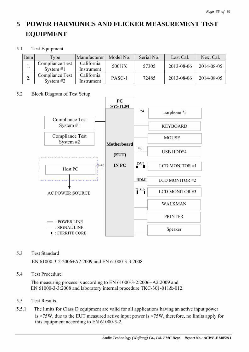
5 POWER HARMONICS AND FLICKER MEASUREMENT TEST EQUIPMENT
5.1 Test Equipment
Item Type Manufacturer Model No. Serial No. Last Cal. Next Cal.
1. Compliance Test System #1
California Instrument 5001iX 57305 2013-08-06 2014-08-05
2. Compliance Test System #2
California Instrument PASC-1 72485 2013-08-06 2014-08-05
5.2 Block Diagram of Test Setup
5.3 Test Standard
EN 61000-3-2:2006+A2:2009 and EN 61000-3-3:2008
5.4 Test Procedure
The measuring process is according to EN 61000-3-2:2006+A2:2009 and EN 61000-3-3:2008 and laboratory internal procedure TKC-301-011&-012.
5.5 Test Results
5.5.1 The limits for Class D equipment are valid for all applications having an active input power is >75W, due to the EUT measured active input power is <75W, therefore, no limits apply for this equipment according to EN 61000-3-2.
Compliance Test System #2
Compliance Test System #1
PC SYSTEM
Host PC
AC POWER SOURCE
: POWER LINE : SIGNAL LINE : FERRITE CORE
KEYBOARD
USB HDD*4
MOUSE
HDMI
*4
WALKMAN
PRINTER
Motherboard
(EUT)
IN PC
LCD MONITOR #2
Earphone *3
D-Sub LCD MONITOR #3
LCD MONITOR #1 RJ-45 DVI
*4
Speaker

Page 37 of 80
Audix Technology (Wujiang) Co., Ltd. EMC Dept. Report No.: ACWE-E1405011
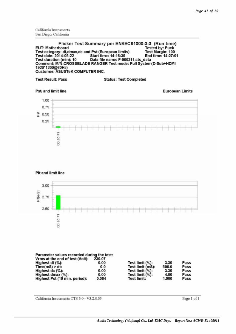
5.5.2 PASSED. (Complied with Class D limit). EUT with the following test modes were measured during this section testing and all the test results are listed in next page. Test Date: May 22, 2014 Temperature: 22.6 Humidity: 49%
Item Test Condition
1 Full System (D-Sub+ HDMI 1920*1200@60Hz)

Page 38 of 80
Audix Technology (Wujiang) Co., Ltd. EMC Dept. Report No.: ACWE-E1405011

Page 39 of 80
Audix Technology (Wujiang) Co., Ltd. EMC Dept. Report No.: ACWE-E1405011

Page 40 of 80
Audix Technology (Wujiang) Co., Ltd. EMC Dept. Report No.: ACWE-E1405011
Page 41 of 80
Audix Technology (Wujiang) Co., Ltd. EMC Dept. Report No.: ACWE-E1405011
Page 42 of 80
Audix Technology (Wujiang) Co., Ltd. EMC Dept. Report No.: ACWE-E1405011
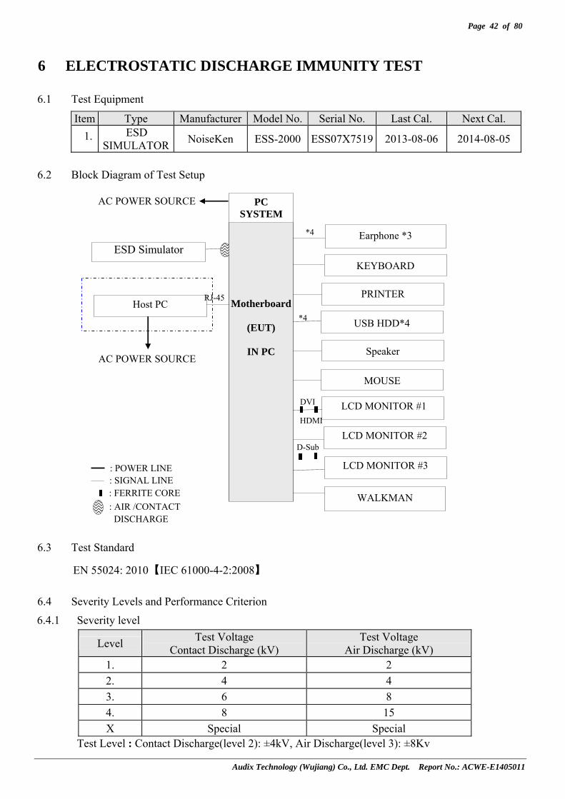
6 ELECTROSTATIC DISCHARGE IMMUNITY TEST
6.1 Test Equipment
Item Type Manufacturer Model No. Serial No. Last Cal. Next Cal. 1. ESD
SIMULATOR NoiseKen ESS-2000 ESS07X7519 2013-08-06 2014-08-05
6.2 Block Diagram of Test Setup
6.3 Test Standard
EN 55024: 2010【IEC 61000-4-2:2008】
6.4 Severity Levels and Performance Criterion
6.4.1 Severity level
Level Test Voltage Contact Discharge (kV)
Test Voltage Air Discharge (kV)
1. 2 2 2. 4 4 3. 6 8 4. 8 15 X Special Special
Test Level : Contact Discharge(level 2): ±4kV, Air Discharge(level 3): ±8Kv
PC SYSTEM
Host PC
AC POWER SOURCE
: POWER LINE: SIGNAL LINE: FERRITE CORE
ESD Simulator
AC POWER SOURCE
: AIR /CONTACT DISCHARGE
KEYBOARD
MOUSE
USB HDD*4
PRINTER
HDMI
*4
WALKMAN
Motherboard
(EUT)
IN PC
LCD MONITOR #2
Earphone *3
D-Sub
LCD MONITOR #3
LCD MONITOR #1
RJ-45
DVI
Speaker
*4

Page 43 of 80
Audix Technology (Wujiang) Co., Ltd. EMC Dept. Report No.: ACWE-E1405011
6.4.2 Performance criterion:B
6.5 Test Procedure
The measuring process is according to EN 55024:2010 (IEC 61000-4-2:2008) and laboratory internal procedure TKC-301-015.
6.5.1 Air Discharge: This test is done on a non-conductive surface. The round discharge tip of the discharge electrode shall be approached as fast as possible to touch the EUT. After each discharge, the ESD generator discharge electrode shall be removed from the EUT. The generator is then ret rigged for a new single discharge and repeated 10 discharges each at positive and negative polarity for each reselected test point. This procedure shall be repeated until all the air discharge completed.
6.5.2 Contact Discharge: All the procedure shall be same as 6.5.1. Except that the tip of the discharge electrode shall touch the EUT conductive surfaces & repeated 25 discharges each at positive and negative polarity for each test point before the discharge switch is operated.
6.5.3 Indirect discharge for horizontal coupling plane:
At least 25 discharges each at positive and negative polarity shall be applied to the horizontal coupling plane, at points on each side of the EUT. The ESD generator positions vertically at a distance of 0.1m from the EUT and with the discharge electrode touching the coupling plane.
6.5.4 Indirect discharge for vertical coupling plane: At least 25 discharges each at positive and negative polarity shall be applied to the center of one vertical edge of the coupling plane. The coupling plane, of dimensions 0.5m×0.5m, is placed parallel to, and positioned at a distance of 0.1m from the EUT. Discharges shall be applied to the coupling plane, with this plane in sufficient different positions that the four faces of the EUT are completely illuminated.
6.5.5 For above tests, the voltage was increased from the minimum to the selected test level.
6.6 Test Results
PASSED. (Complied with Criterion A) EUT was tested with the following test mode and all the test results are listed in next page.
Item Test Condition
1 Full System (D-Sub+ HDMI 1920*1200@60Hz)
Page 44 of 80
Audix Technology (Wujiang) Co., Ltd. EMC Dept. Report No.: ACWE-E1405011
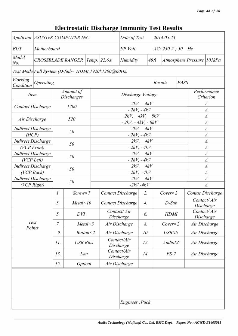
Electrostatic Discharge Immunity Test Results
Applicant ASUSTeK COMPUTER INC. Date of Test 2014.05.23
EUT Motherboard I/P Volt. AC: 230 V ; 50 Hz
Model No. CROSSBLADE RANGER Temp. 22.6 Humidity 49% Atmosphere Pressure 101kPa
Test Mode Full System (D-Sub+ HDMI 1920*1200@60Hz)
Working Condition Operating Results PASS
Item Amount of Discharges Discharge Voltage Performance
Criterion ﹢2kV,﹢4kV A Contact Discharge 1200 - 2kV, - 4kV A
﹢2kV,﹢4kV,﹢8kV A Air Discharge 520 - 2kV, - 4kV, - 8kV A
Indirect Discharge ﹢2kV,﹢4kV A (HCP)
50 - 2kV, - 4kV A
Indirect Discharge ﹢2kV,﹢4kV A (VCP Front)
50 - 2kV, - 4kV A
Indirect Discharge ﹢2kV,﹢4kV A (VCP Left)
50 - 2kV, - 4kV A
Indirect Discharge ﹢2kV,﹢4kV A (VCP Back)
50 - 2kV, - 4kV A
Indirect Discharge ﹢2kV,﹢4kV A (VCP Right)
50 -2kV,-4kV A
1. Screw×7 Contact Discharge 2. Cover×2 Contac Discharge
3. Metal×10 Contact Discharge 4. D-Sub Contact/ Air Discharge
5. DVI Contact/ Air Discharge 6. HDMI Contact/ Air
Discharge 7. Metal×3 Air Discharge 8. Cover×2 Air Discharge
9. Button×2 Air Discharge 10. USBX6 Air Discharge
11. USB Bios Contact/Air Discharge 12. AudioX6 Air Discharge
13. Lan Contact/Air Discharge 14. PS-2 Air Discharge
Test Points
15. Optical Air Discharge
Engineer :Puck

Page 45 of 80
Audix Technology (Wujiang) Co., Ltd. EMC Dept. Report No.: ACWE-E1405011
Photos of Discharge Points:
8
2
3
3
1
5
2
1
3
3
3 3
8
7
3
3
46
10
1
1
10
13
12
1
1
1
3
3
14
15
11

Page 46 of 80
Audix Technology (Wujiang) Co., Ltd. EMC Dept. Report No.: ACWE-E1405011
7
9
9

Page 47 of 80
Audix Technology (Wujiang) Co., Ltd. EMC Dept. Report No.: ACWE-E1405011
7

Page 48 of 80
Audix Technology (Wujiang) Co., Ltd. EMC Dept. Report No.: ACWE-E1405011
7 RF FIELD STRENGTH IMMUNITY TEST
7.1 Test Equipment
Item Type Manufacturer Model No. Serial No. Last Cal. Next Cal.1. Signal Generator Agilent 8648C 3847M01438 2014-01-05 2015-01-042. Power Amplifier AR KAW 2180 10088-2 NCR NCR 3. Power Sensor Agilent 8481D MY41093045 2014-01-05 2015-01-044. Power Meter Agilent E4419B MY45100928 2014-01-05 2015-01-04
5. Log-Periodic Antenna AR AT1080 0323131 NCR NCR
6. Direction Coupler AR DC6180A 322333 2013-08-05 2014-08-04NCR: Non-Calibration Requirement.
7.2 Block Diagram of Test Setup
7.2.1 Block Diagram of connection between EUT and simulators.
Host PC
AC POWER SOURCE
: POWER LINE: SIGNAL LINE : FERRITE CORE
AC POWER SOURCE
PC SYSTEM
WALKMAN
KEYBOARD
MOUSE
USB HDD*4
PRINTER
HDMI
*4
Motherboard
(EUT)
IN PC
LCD MONITOR #2
Earphone *3
LCD MONITOR #3
LCD MONITOR #1
D-Sub
RJ-45
DVI
*4
Speaker

Page 49 of 80
Audix Technology (Wujiang) Co., Ltd. EMC Dept. Report No.: ACWE-E1405011
7.2.2 R/S Test Setup
7.3 Test Standard
EN 55024:2010【IEC 61000-4-3:2006+A2:2010】
7.4 Severity Levels and Performance Criterion
7.4.1 Severity level
Level Field Strength V/m
1. 1
2. 3
3. 10
X Special Test Level:2; Field strength: 3V/m
7.4.2 Performance criterion:A
EUT
0.8 Meter
1 Meter
Anechoic Chamber
Control Room Direction Coupler
Signal Generator Personal Computer
3 Meters
Power Amp.
Power Sensor Power Monitor

Page 50 of 80
Audix Technology (Wujiang) Co., Ltd. EMC Dept. Report No.: ACWE-E1405011
7.5 Test Procedure
The measuring process is according to EN 55024:2010 (IEC 61000-4-3:2006+A2:2010) and laboratory internal procedure TKC-301-016.
The field sensor is placed on the EUT table (0.8 meter above the ground) which is 3 meter away from the transmitting antenna. Through the signal generator, power amplifier and transmitting antenna to produce a uniformity field strength (3V/m measured by field sensor) around the EUT table from frequency range 80MHz to 1000MHz and records the signal generator‘s output level at the same time for whole measured frequency range. Then, put EUT and its simulators on the EUT turn table and keep them 3 meter away from the transmitting antenna which is mounted on an antenna tower and fixes at 1 meter height above the ground. Using the recorded signal generator’s output level to measure the EUT from frequency range 80MHz to 1000MHz and both horizontal & vertical polarization of antenna must be set and measured. Each of the four sides of EUT must be faced this transmitting antenna and measures individually.
A CCD camera was put inside the chamber and through its display to monitor the EUT operational situation to judge the EUT performance criterion during measurement.
All the scanning conditions are as follows:
Condition of Test Remarks -------------------------------------- ----------------------------------
1. Fielded Strength 3 V/m (Unmodulated, Severity Level 2) 2. Amplitude Modulated 1kHz, 80%AM 3. Scanning Frequency 80 – 1000MHz 4. Step Size 1% increments 5. The Rate of Sweep 0.0015 decade/s 6. Dwell Time 3 sec.
7.6 Test Results
PASSED. (Complied with Criterion A) EUT was tested with the following test mode and all the test results are listed in next page.
Item Test Condition
1 Full System (D-Sub+ HDMI 1920*1200@60Hz)

Page 51 of 80
Audix Technology (Wujiang) Co., Ltd. EMC Dept. Report No.: ACWE-E1405011
RF Field Strength Immunity Test Results Applicant ASUSTeK COMPUTER INC. Date of Test 2014.05.23
EUT Motherboard I/P Volt. AC: 230 V ; 50Hz
Model No. CROSSBLADE RANGER Temp. 22.0 Humidity 65%
Test Mode Full System (D-Sub+ HDMI 1920*1200@60Hz)
Working Condition Operating Results PASS
Frequency Range (MHz)
E.U.T. Position ( Angle )
Ant. Polarity(Hor. or Ver.)
Field Strength (V/m)
Performance Criterion Remark
80~1000 0 H 3 A
80~1000 90 H 3 A
80~1000 180 H 3 A
80~1000 270 H 3 A
80~1000 0 V 3 A
80~1000 90 V 3 A
80~1000 180 V 3 A
80~1000 270 V 3 A
Engineer : Ody

Page 52 of 80
Audix Technology (Wujiang) Co., Ltd. EMC Dept. Report No.: ACWE-E1405011
8 ELECTRICAL FAST TRANSIENT/BURST IMMUNITY TEST
8.1 Test Equipment
Item Type Manufacturer Model No. Serial No. Last Cal. Next Cal.
1. Electrical Fast Transien Generator
3C TEST EFT-4003G EC0471226 2013-08-06 2014-08-05
8.2 Block Diagram of Test Setup
8.2.1 Block Diagram of connection between EUT and simulators. Same as section 7.2.1.
8.2.2 EFT Test Setup
8.3 Test Standard
EN 55024:2010【IEC 61000-4-4:2012】
Ground Plane
Remark: Combination wave generator and decoupling networks are included in test.
To AC Power Supply Network
AC Line (L=50cm)
EUT
ECAT system
TABLE
EFT Clamp
Signal Line
Grounding Wire
10cm insulating support
Grounding Plate
Page 53 of 80
Audix Technology (Wujiang) Co., Ltd. EMC Dept. Report No.: ACWE-E1405011
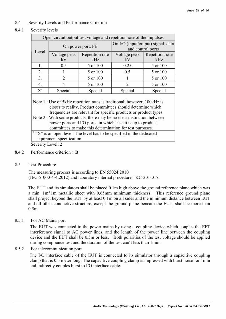
8.4 Severity Levels and Performance Criterion
8.4.1 Severity levels Open circuit output test voltage and repetition rate of the impulses
On power port, PE On I/O (input/output) signal, data and control ports Level Voltage peak
kV Repetition rate
kHz Voltage peak
kV Repetition rate
kHz 1. 0.5 5 or 100 0.25 5 or 100 2. 1 5 or 100 0.5 5 or 100 3. 2 5 or 100 1 5 or 100 4. 4 5 or 100 2 5 or 100 Xa Special Special Special Special
Note 1 : Use of 5kHz repetition rates is traditional; however, 100kHz is
closer to reality. Product committees should determine which frequencies are relevant for specific products or product types.
Note 2 : With some products, there may be no clear distinction between power ports and I/O ports, in which case it is up to product committees to make this determination for test purposes.
a “X” is an open level. The level has to be specified in the dedicated equipment specification.
Severity Level: 2
8.4.2 Performance criterion:B
8.5 Test Procedure
The measuring process is according to EN 55024:2010 (IEC 61000-4-4:2012) and laboratory internal procedure TKC-301-017.
The EUT and its simulators shall be placed 0.1m high above the ground reference plane which was a min. 1m*1m metallic sheet with 0.65mm minimum thickness. This reference ground plane shall project beyond the EUT by at least 0.1m on all sides and the minimum distance between EUT and all other conductive structure, except the ground plane beneath the EUT, shall be more than 0.5m.
8.5.1 For AC Mains port
The EUT was connected to the power mains by using a coupling device which couples the EFT interference signal to AC power lines, and the length of the power line between the coupling device and the EUT shall be 0.5m or less. Both polarities of the test voltage should be applied during compliance test and the duration of the test can‘t less than 1min.
8.5.2 For telecommunication port The I/O interface cable of the EUT is connected to its simulator through a capacitive coupling clamp that is 0.5 meter long. The capacitive coupling clamp is impressed with burst noise for 1min and indirectly couples burst to I/O interface cable.

Page 54 of 80
Audix Technology (Wujiang) Co., Ltd. EMC Dept. Report No.: ACWE-E1405011
8.6 Test Results
PASSED. (Complied with Criterion A) EUT was tested with the following test mode and all the test results are listed in next page.
Item Test Condition
1 Full System (D-Sub+ HDMI 1920*1200@60Hz)

Page 55 of 80
Audix Technology (Wujiang) Co., Ltd. EMC Dept. Report No.: ACWE-E1405011
Electrical Fast Transient / Burst Immunity Test Results
Applicant ASUSTeK COMPUTER INC. Date of Test 2014.05.23
EUT Motherboard I/P Volt. AC: 230 V ; 50 Hz
Model No. CROSSBLADE RANGER Temp. 22.6 Humidity 49%
Test Mode Full System (D-Sub+ HDMI 1920*1200@60Hz)
Working Condition Operating Results PASS
Inject Place: Power Supply Line Inject Place: I/O Cable
Inject Line
Voltage (kV)
Inject Time(s)
Inject Method
Performance Criterion
Inject Line
Voltage (kV)
Inject Time(s)
Inject Method
Performance Criterion
L1 +0.5, +1.0 60 Direct A I/O +0.25,+0.5 60 Clamp A L1 -0.5, -1.0 60 Direct A I/O -0.25,-0.5 60 Clamp A L2 +0.5, +1.0 60 Direct A L2 -0.5, -1.0 60 Direct A PE +0.5, +1.0 60 Direct A PE -0.5, -1.0 60 Direct A
L1,L2 +0.5, +1.0 60 Direct A L1,L2 -0.5, -1.0 60 Direct A L1,PE +0.5, +1.0 60 Direct A L1,PE -0.5, -1.0 60 Direct A L2,PE +0.5, +1.0 60 Direct A L2,PE -0.5, -1.0 60 Direct A
L1,L2,PE +0.5, +1.0 60 Direct A L1,L2,PE -0.5, -1.0 60 Direct A
Engineer: Puck

Page 56 of 80
Audix Technology (Wujiang) Co., Ltd. EMC Dept. Report No.: ACWE-E1405011
9 SURGE IMMUNITY TEST
9.1 Test Equipment
Item Type Manufacturer Model No. Serial No. Last Cal. Next Cal. 1. ECAT System KEYTEK E501B 0605187 2013-08-06 2014-08-05
9.2 Block Diagram of Test Setup
9.2.1 Block Diagram of connection between EUT and simulators. Same as section 7.2.1.
9.2.2 Test Setup
9.3 Test Standard
EN 55024:2010【IEC 61000-4-5:2005】
Remark: Test generator includes control center、surge combination and coupler.
80cm To AC Power Supply Network
AC Line EUT
Ground Plane
Coupler/ Decoupler
Telecom. Line
Test Generator
TABLE

Page 57 of 80
Audix Technology (Wujiang) Co., Ltd. EMC Dept. Report No.: ACWE-E1405011
9.4 Severity Levels and Performance Criterion
9.4.1 Test Levels
Level Open-circuit test Voltage +/- 10%, kV
1. 0.5
2. 1.0
3. 2.0
4. 4.0
X Special Test Level: (1) For AC Main: line to earth - ± 2kV, line to line - ± 1kV, waveform 1.2/50 (8/20) Tr/Thµs. (2) For Telecom port: ± 1kV directly connect outdoor cable ± 4kV with primary protection wave
form 10/700 Tr/Thµs. Note: According to the requirement of Table 2 note(g) of EN55024 2010, Where the coupling
network for the 10/700 µs waveform affects the functioning of high speed data ports, the test shall be carried out using a 1,2/50 (8/20) µs waveform and appropriate coupling network.
9.4.2 Performance Criterion
(1) For AC Main: B (2) For Telecom Port: C
9.5 Test Procedure
The measuring process is according to EN 55024: 2010 (IEC 61000-4-5:2005) and laboratory internal procedure TKC-301-018.
For AC Mains ports: 9.5.1 Set up the EUT and test generator as shown on section 9.2. 9.5.2 For line to line coupling mode, provided a 0.5/1kV 1.2/50 μs voltage surge (at open-circuit
condition) and 8/20 μs current surge to EUT selected points. 9.5.3 At least 5 positive and 5 negative (polarity) tests with a Maximum 1/min repetition rate
were conducted during test. 9.5.4 Different phase angles were done individually. 9.5.5 Repeat procedure 9.5.2. to 9.5.4. except the open-circuit test voltages 0.5kV/1kV/2kV for line
to earth coupling mode test. 9.5.6 Record the EUT Operating situation during compliance test and decide the EUT
immunity criterion for above each test.
For Telecommunication ports:
9.5.7 Set up the EUT and test generator as shown on section 9.2. 9.5.8 For line to line coupling mode, provided a 0.5/1kV 10/700 μs voltage surge (at
open-circuit condition) and 5/320 μs current surge to EUT selected points. 9.5.9 At least 5 positive and 5 negative (polarity) tests with a Maximum 1/min repetition rate
were conducted during test. 9.5.10 Repeat procedure 9.5.8. to 9.5.9 for line to earth coupling mode test. 9.5.11 Record the EUT Operating situation during compliance test and decide the EUT
immunity criterion for above each test.

Page 58 of 80
Audix Technology (Wujiang) Co., Ltd. EMC Dept. Report No.: ACWE-E1405011
9.6 Test Results
PASSED. (Complied with Criterion A).
EUT was tested with the following test mode and all the test results are listed in next page.
Note: Due to the coupling network could not be connected with high speed function during test, the waveform 1,2/50 (8/20) µs was used to carry out.
Item Test Condition
1 Full System (D-Sub+ HDMI 1920*1200@60Hz)

Page 59 of 80
Audix Technology (Wujiang) Co., Ltd. EMC Dept. Report No.: ACWE-E1405011
Surge Immunity Test Results
Applicant ASUSTeK COMPUTER INC. Date of Test 2014.05.23
EUT Motherboard I/P Volt. AC: 230 V ; 50Hz
Model No. CROSSBLADE RANGER Temp. 22.6 Humidity 49%
Test Mode Full System (D-Sub+ HDMI 1920*1200@60Hz)
Working Condition Operating Results PASS
Input and Output AC Power Port
Location Polarity Phase Angle
No of Pulse Pulse Voltage Performance
Criterion + 0 5 0.5kV, 1.0kV A+ 90 5 0.5kV, 1.0kV A+ 180 5 0.5kV, 1.0kV A+ 270 5 0.5kV ,1.0kV A- 0 5 0.5kV ,1.0kV A- 90 5 0.5kV , 1.0kV A- 180 5 0.5kV , 1.0kV A
L-N
- 270 5 0.5kV , 1.0kV A+ 0 5 0.5kV, 1.0kV , 2.0kV A+ 90 5 0.5kV, 1.0kV , 2.0kV A+ 180 5 0.5kV, 1.0kV , 2.0kV A+ 270 5 0.5kV, 1.0kV , 2.0kV A- 0 5 0.5kV, 1.0kV , 2.0kV A- 90 5 0.5kV, 1.0kV , 2.0kV A- 180 5 0.5kV, 1.0kV , 2.0kV A
L-PE
- 270 5 0.5kV, 1.0kV , 2.0kV A+ 0 5 0.5kV, 1.0kV , 2.0kV A+ 90 5 0.5kV, 1.0kV , 2.0kV A+ 180 5 0.5kV, 1.0kV , 2.0kV A+ 270 5 0.5kV, 1.0kV , 2.0kV A- 0 5 0.5kV, 1.0kV , 2.0kV A- 90 5 0.5kV, 1.0kV , 2.0kV A- 180 5 0.5kV, 1.0kV , 2.0kV A
N-PE
- 270 5 0.5kV, 1.0kV , 2.0kV A+ 0 5 0.5kV, 1.0kV , 2.0kV A+ 90 5 0.5kV, 1.0kV , 2.0kV A+ 180 5 0.5kV, 1.0kV , 2.0kV A+ 270 5 0.5kV, 1.0kV , 2.0kV A- 0 5 0.5kV, 1.0kV , 2.0kV A- 90 5 0.5kV, 1.0kV , 2.0kV A- 180 5 0.5kV, 1.0kV , 2.0kV A
L, N-PE
- 270 5 0.5kV, 1.0kV , 2.0kV A
Engineer: Puck

Page 60 of 80
Audix Technology (Wujiang) Co., Ltd. EMC Dept. Report No.: ACWE-E1405011
Surge Immunity Test Results Applicant ASUSTeK COMPUTER INC. Date of Test 2014.05.23
EUT Motherboard I/P Volt. AC: 230 V ; 50Hz
Model No. CROSSBLADE RANGER Temp. 22.6 Humidity 49%
Test Mode Full System (D-Sub+ HDMI 1920*1200@60Hz)
Working Condition Operating Results PASS
Telecom Line Coupling Performance Line Polarity No of
Pulse Pulse Voltage Criterion
+ 5 0.5kV 1kV N/A T1 - 5 0.5kV 1kV N/A + 5 0.5kV 1kV N/A R1 - 5 0.5kV 1kV N/A + 5 0.5kV 1kV N/A T2 - 5 0.5kV 1kV N/A + 5 0.5kV 1kV N/A R2 - 5 0.5kV 1kV N/A + 5 0.5kV 1kV N/A T1, R1 - 5 0.5kV 1kV N/A + 5 0.5kV 1kV N/A T2, R2 - 5 0.5kV 1kV N/A + 5 0.5kV 1kV N/A T1, R1, T2, R2 - 5 0.5kV 1kV N/A
[ ]DC Input and Output Power Port ⁄[√]I/O Signal Cable
No of Performance Location Polarity
Pulse Pulse Voltage
Criterion Differential + 5 0.5kV 1kV N/A
Mode - 5 0.5kV 1kV N/A Common + 5 0.5kV 1kV A
Mode - 5 0.5kV 1kV A Note:
1. N/A means not applicable. 2. I/O:RJ-45
Engineer: Puck

Page 61 of 80
Audix Technology (Wujiang) Co., Ltd. EMC Dept. Report No.: ACWE-E1405011
10 CONDUCTED DISTURBANCE IMMUNITY TEST
10.1 Test Equipment
Item Type Manufacturer Model No. Serial No. Last Cal. Next Cal. 1. Signal Generator Agilent 8648C 3847M01438 2014-01-05 2015-01-042. Power Amplifier AR KAW 2180 10088-2 NCR NCR
3. Attenuator ShanghaiHuaxiang DC-1GHz 6092701 2014-01-05 2015-01-04
4. CDN-M3 FCC FCC-801-M3-25A 6041 NCR NCR 5. CDN-M3 FCC FCC-801-M3-25A 6042 2014-01-05 2015-01-04
6. Decoupling Network FCC F-203I-23MM-DC
N 196 NCR NCR
7. EM Injection Clamp FCC F-203I-03MM 503 2014-01-05 2015-01-04
NCR: Non-Calibration Requirement.
10.2 Block Diagram of Test Setup
10.2.1 Block Diagram of connection between EUT and simulators.
Same as Section 7.2.1.
10.2.2 Common Mode Test Setup
EUT AC SourceCDN
Signal Generator
Personal Computer Control System
Ground Reference support
0.1m
Power Amplifier Attenuator
10.2.3 EM Clamp Mode Test Setup
EUTCDN
Signal Generator
Personal Computer Control System
Ground Reference support
Power Amplifier
EM Injection Clamp
AE CDN
50Ω
0.1m 0.1m
0.1m < L <0.3m
Attenuator
50Ω
10.3 Test Standard
EN 55024:2010【IEC 61000-4-6:2008】

Page 62 of 80
Audix Technology (Wujiang) Co., Ltd. EMC Dept. Report No.: ACWE-E1405011
10.4 Severity Levels and Performance Criterion
10.4.1 Severity levels Frequency range 0.15MHz - 80MHz
Voltage level (e.m.f.) Level U0
dB(µV) U0 V
1. 120 1 2. 130 3 3. 140 10 Xa Special
a X is an open level. Severity Level:0.15-80MHz, 3V, 80%AM (1kHz)
10.4.2 Performance criterion:A
10.5 Test Procedure
The measuring process is according to EN 55024:2010 (IEC 61000-4-6:2008) and laboratory internal procedure TKC-301-019. For AC Mains port
10.5.1 Set up the EUT, CDN and test generators as shown on section 10.2.2. 10.5.2 The EUT and supporting equipment were placed on an insulating support 0.1m high above
a ground reference plane. CDN (coupling and decoupling device) was placed on the ground plane making contact with it at about 0.1-0.3m from EUT. Cables between CDN and EUT were as short as possible.
10.5.3 The disturbance signal described below was injected to EUT through CDN. 10.5.4 The EUT operates within its operational mode(s) under intended climatic conditions after
power on. 10.5.5 The frequency range was swept from 150 kHz to 80MHz using 3V signal level, and with
the disturbance signal 80% amplitude modulated with a 1 kHz sine wave. 10.5.6 The rate of sweep shall not exceed 1.5*10^3decades/s. Where the frequency was
swept incrementally, the step size shall not exceed 1% of the start and thereafter 1% of the preceding frequency value.
10.5.7 Recording the EUT Operating situation during compliance testing and decide the EUT immunity criterion.
For Telecommunication Port
10.5.8 Set up the EUT, EM Injection Clamp and test generators as shown on section 10.2.3.
10.5.9 The EUT and supporting equipment were placed on an insulating support 0.1m high above
a ground reference plane. EM Injection Clamp (coupling and decoupling device) was placed on the ground plane making contact with it at about 0.1-0.3m from EUT. Cables between CDN and EUT were as short as possible.
10.5.10 The CDN was placed on between AE and EUT, the EUT and AE of power through CDN, CDN terminated with 50Ω at the RF disturbance input port.
10.5.11 The disturbance signal described below was injected to EUT though EM Injection Clamp. 10.5.12 Repeat above procedure from 10.5.9 to 10.5.11.

Page 63 of 80
Audix Technology (Wujiang) Co., Ltd. EMC Dept. Report No.: ACWE-E1405011
10.6 Test Results
PASSED. (Complied with Criterion A) EUT was tested with the following test mode and all the test results are listed in next page.
Item Test Condition
1 Full System (D-Sub+ HDMI 1920*1200@60Hz)
Page 64 of 80
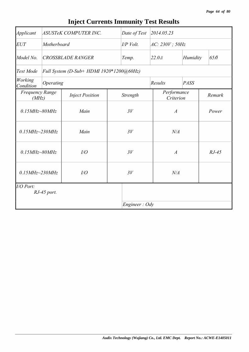
Audix Technology (Wujiang) Co., Ltd. EMC Dept. Report No.: ACWE-E1405011
Inject Currents Immunity Test Results Applicant ASUSTeK COMPUTER INC. Date of Test 2014.05.23
EUT Motherboard I/P Volt. AC: 230V ; 50Hz
Model No. CROSSBLADE RANGER Temp. 22.0 Humidity 65%
Test Mode Full System (D-Sub+ HDMI 1920*1200@60Hz)
Working Condition Operating Results PASS
Frequency Range (MHz) Inject Position Strength Performance
Criterion Remark
0.15MHz~80MHz Main 3V A Power
0.15MHz~230MHz Main 3V N/A
0.15MHz~80MHz I/O 3V A RJ-45
0.15MHz~230MHz I/O 3V N/A
I/O Port: RJ-45 port.
Engineer : Ody

Page 65 of 80
Audix Technology (Wujiang) Co., Ltd. EMC Dept. Report No.: ACWE-E1405011
11 POWER FREQUENCY MAGNETIC FIELD IMMUNITY TEST
11.1 Test Equipment
Item Type Manufacturer Model No. Serial No. Last Cal. Next Cal.
1. Power Frequency Magenetic Field
Generator 3C TEST PFMF-6108G EC0881205 2013-08-06 2014-08-05
NCR: Non-Calibration Requirement.
11.2 Block Diagram of Test Setup
11.2.1 Block Diagram of connection between EUT and simulators. Same as section 7.2.1.
11.2.2 Test Setup
Test Generator
Induction Coil EUT
Non-Conductive Table
11.3 Test Standard
EN 55024:2010【IEC 61000-4-8:2009】
11.4 Severity Levels and Performance Criterion
11.4.1 Severity level
Level Magnetic Field Strength Continuous Field A/m 1. 1 2. 3 3. 10 4. 30 5. 100 X Special
Test Level: 50Hz, 1A/m
11.4.2 Performance criterion:A

Page 66 of 80
Audix Technology (Wujiang) Co., Ltd. EMC Dept. Report No.: ACWE-E1405011
11.5 Test Procedure
The measuring process is according to EN 55024:2010 (IEC 61000-4-8:2009) and laboratory internal procedure TKC-301-020.
The EUT was placed on 1m high table that above the ground reference plane which is the min. size 1m x 1m and 0.65mm thickness metallic. And subjected to the test magnetic field by using the induction coil of standard dimensions (1m x 1m). The induction coil rotated by 90 degrees in order to expose the EUT to the test field with different orientations. All cables of EUT exposed to magnetic field for 1m of their length.
11.6 Test Results
PASSED. (Complied with Criterion A) EUT was tested with the following test mode and all the test results are listed in next page.
Item Test Condition
1 Full System (D-Sub+ HDMI 1920*1200@60Hz)

Page 67 of 80
Audix Technology (Wujiang) Co., Ltd. EMC Dept. Report No.: ACWE-E1405011
Power Frequency Magnetic Field Immunity Test Results Applicant ASUSTeK COMPUTER INC. Date of Test 2014.05.23
EUT Motherboard I/P Volt. AC: 230 V ; 50 Hz
Model No. CROSSBLADE RANGER Temp. 22.6 Humidity 49%
Test Mode Full System (D-Sub+ HDMI 1920*1200@60Hz)
Working Condition Operating Results PASS
Power Frequency Magnetic Field Testing Duration Coil Orientation Performance Criterion Remark
50Hz,1A/m 1 Min. X-axis A
50Hz,1A/m 1 Min. Y-axis A
50Hz,1A/m 1 Min. Z-axis A
Engineer: Puck

Page 68 of 80
Audix Technology (Wujiang) Co., Ltd. EMC Dept. Report No.: ACWE-E1405011
12 VOLTAGE DIPS AND INTERRUPTIONS IMMUNITY TEST
12.1 Test Equipment
Item Type Manufacturer Model No. Serial No. Last Cal. Next Cal.
1. Plus Immunity Test System KEYTEK EMC pro 0604251 2014-01-05 2015-01-04
12.2 Block Diagram of Test Setup
12.2.1 Block Diagram of connection between EUT and simulators. Same as section 7.2.1.
12.2.2 Test Setup
12.3 Test Standard
EN 55024:2010【IEC 61000-4-11:2004】
12.4 Severity Levels and Performance Criterion
12.4.1 Preferred severity levels and durations for voltage dips
Classa Test level and durations for voltage dips (ts) (50Hz/60Hz)
Class 1 Case-by-case according to the equipment requirements
Class 2 0% during ½ cycle
0% during 1 cycle
70% during 25/30c cycles
Class 3 0% during ½ cycle
0% during 1 cycle
40% during 10/12c cycles
70% during 25/30c cycles
80% during 250/300c cycles
Class Xb X X X X X a Classes as per IEC 61000-2-4. b To be defined by product committee. For equipment connected directly or indirectly
to the public network, the levels must not be less severe than Class 2. c “25/30 cycles” means “25 cycles for 50Hz test” and “30 cycles for 60Hz test”.
EUT
AC Line
O/P
To AC Power Supply Network
Plus Immunity Test System
I/P

Page 69 of 80
Audix Technology (Wujiang) Co., Ltd. EMC Dept. Report No.: ACWE-E1405011
12.4.2 Preferred severity levels and durations for short interruptions
Classa Test level and durations for short interruptions (ts) (50Hz/60Hz)
Class 1 Case-by-case according to the equipment requirements
Class 2 0% during 250/300c cycles
Class 3 80% during 250/300c cycles
Class Xb X a Classes as per IEC 61000-2-4. b To be defined by product committee. For equipment connected directly or indirectly
to the public network, the levels must not be less severe than Class 2. c “250/300 cycles” means “250 cycles for 50Hz test” and “300 cycles for 60Hz test”.
Severity Level:Voltage dips : Voltage interruptions >95% reduction: 250period; Dips 30% reduction: 25period; >95% reduction: 0.5period
12.4.3 Performance criterion: 1) Voltage dips >95% reduction performance criterion B. 2) Voltage dips 30% reduction performance criterion C. 3) Voltage interruption >95% reduction performance criterion C.
12.5 Test Procedure
The measuring process is according to EN 55024:2010 (IEC 61000-4-11:2004) and laboratory internal procedure TKC-301-021.
12.5.1 Set up the EUT and test generator as shown on section 12.2. 12.5.2 The interruption was introduced at selected phase angles with specified duration. There was a
10s minimum interval between each test event. 12.5.3 After each test a full functional check was performed before the next test. 12.5.4 Repeat procedures 12.5.2.. & 12.5.3. for voltage dips, only the test level and duration
was changed. 12.5.5 Record any degradation of performance.
12.6 Test Results
PASSED. (Voltage interruptions complied with criterion C, Voltage dips Complied with criterion A) EUT was tested with the following test mode and all the test results are listed in next page.
Item Test Condition
1 Full System (D-Sub+ HDMI 1920*1200@60Hz)

Page 70 of 80
Audix Technology (Wujiang) Co., Ltd. EMC Dept. Report No.: ACWE-E1405011
Voltage Dips and Interruptions Immunity Test Results
Applicant ASUSTeK COMPUTER INC. Date of Test 2014.05.23
EUT Motherboard I/P Volt. AC: 230 V ; 50 Hz
Model No. CROSSBLADE RANGER Temp. 22.6 Humidity 49%
Test Mode Full System (D-Sub+ HDMI 1920*1200@60Hz)
Working Condition Operating Results PASS
Type of Test
Test Voltage Phase Angle % Reduction Period
PerformanceCriterion
0 >95% 250 C 45 >95% 250 C 90 >95% 250 C 135 >95% 250 C 180 >95% 250 C 225 >95% 250 C 270 >95% 250 C
Voltage Interruption 230
315 >95% 250 C 0 30% 25 A 45 30% 25 A 90 30% 25 A 135 30% 25 A 180 30% 25 A 225 30% 25 A 270 30% 25 A
230
315 30% 25 A 0 >95% 0.5 A 45 >95% 0.5 A 90 >95% 0.5 A 135 >95% 0.5 A 180 >95% 0.5 A 225 >95% 0.5 A 270 >95% 0.5 A
Voltage Dips
230
315 >95% 0.5 A
Note: The performance criterion “C” means the
power of the EUT is turned off, and it cannotrecover by itself during the test interval .
Engineer Puck

Page 71 of 80
Audix Technology (Wujiang) Co., Ltd. EMC Dept. Report No.: ACWE-E1405011
13 PHOTOGRAPHS
13.1 Photos of Conducted Disturbance Measurement
Front View of Conducted Measurement (AC Mains Port)
Side View of Conducted Measurement (AC Mains Port)

Page 72 of 80
Audix Technology (Wujiang) Co., Ltd. EMC Dept. Report No.: ACWE-E1405011
Front View of Conducted Emission Measurement (Telecommunication port)
Side View of Conducted Emission Measurement (Telecommunication port)

Page 73 of 80
Audix Technology (Wujiang) Co., Ltd. EMC Dept. Report No.: ACWE-E1405011
13.2 Photos of Radiated Disturbance Measurement For 30MHz ~1GHz
Front View of Radiated Disturbance Measurement
Back View of Radiated Disturbance Measurement

Page 74 of 80
Audix Technology (Wujiang) Co., Ltd. EMC Dept. Report No.: ACWE-E1405011
For above 1GHz
Front View of Radiated Measurement
Back View of Radiated Measurement

Page 75 of 80
Audix Technology (Wujiang) Co., Ltd. EMC Dept. Report No.: ACWE-E1405011
13.3 Photos of Harmonic & Flicker Measurement
13.4 Photos of Electrostatic Discharge Immunity Test
Contact & Air Discharge

Page 76 of 80
Audix Technology (Wujiang) Co., Ltd. EMC Dept. Report No.: ACWE-E1405011
VCP & HCP
13.5 Photos of RF Field Strength Immunity Test
Front View of R/S Test
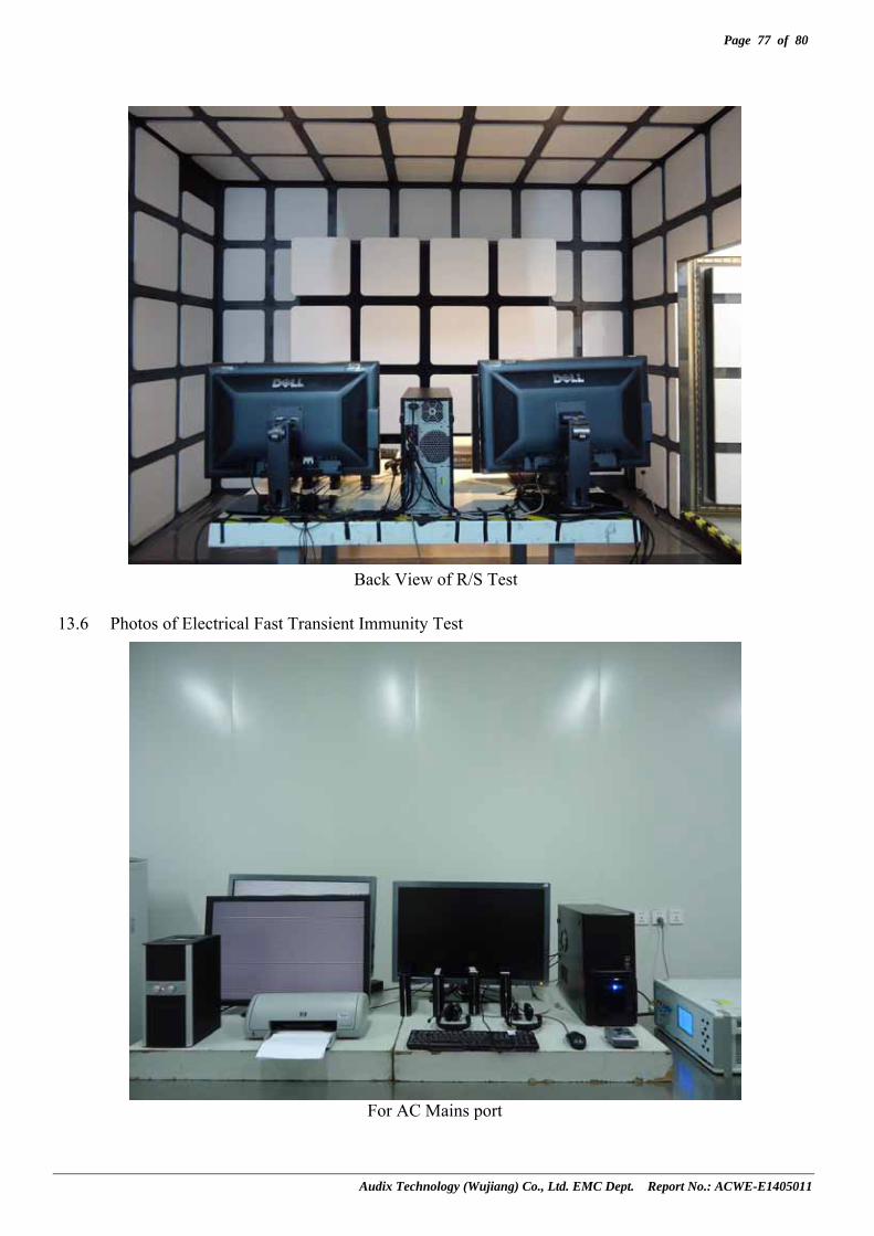
Page 77 of 80
Audix Technology (Wujiang) Co., Ltd. EMC Dept. Report No.: ACWE-E1405011
Back View of R/S Test
13.6 Photos of Electrical Fast Transient Immunity Test
For AC Mains port

Page 78 of 80
Audix Technology (Wujiang) Co., Ltd. EMC Dept. Report No.: ACWE-E1405011
For Telecommunication port
13.7 Photos of Surge Immunity Test
For AC Mains port
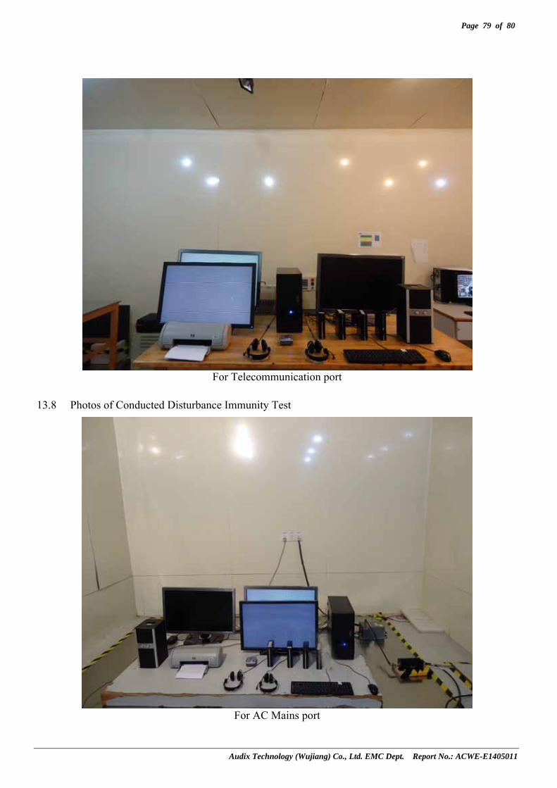
Page 79 of 80
Audix Technology (Wujiang) Co., Ltd. EMC Dept. Report No.: ACWE-E1405011
For Telecommunication port
13.8 Photos of Conducted Disturbance Immunity Test
For AC Mains port

Page 80 of 80
Audix Technology (Wujiang) Co., Ltd. EMC Dept. Report No.: ACWE-E1405011
For Telecommunication port
13.9 Photos of Power Frequency Magnetic Field Immunity Test

Page 81 of 80
Audix Technology (Wujiang) Co., Ltd. EMC Dept. Report No.: ACWE-E1405011
13.10 Photos of Voltage Dips and Interruptions Immunity Test
13.11 Photos of Host PC for RJ-45 Ping Test

APPENDIX I
Audix Technology (Wujiang) Co., Ltd. EMC Dept. Report No.: ACWE-E1405011
APPENDIX I
Photos of EUT

APPENDIX I - Page 1 of 8
Audix Technology (Wujiang) Co., Ltd. EMC Dept. Report No.: ACWE-E1405011
Figure 1 General Appearance (Motherboard, Front View)
Figure 2 General Appearance (Motherboard, Back View)

APPENDIX I - Page 2 of 8
Audix Technology (Wujiang) Co., Ltd. EMC Dept. Report No.: ACWE-E1405011
Figure 3 Fan Set Removed
Figure 4 Fan Set (Front View)

APPENDIX I - Page 3 of 8
Audix Technology (Wujiang) Co., Ltd. EMC Dept. Report No.: ACWE-E1405011
Figure 5
Fan Set (Back View)
Figure 6 General Appearance (Motherboard, Fan Set Removed)

APPENDIX I - Page 4 of 8
Audix Technology (Wujiang) Co., Ltd. EMC Dept. Report No.: ACWE-E1405011
Figure 7 General Appearance (Motherboard, I/O Ports)
Figure 8 CPU

APPENDIX I - Page 5 of 8
Audix Technology (Wujiang) Co., Ltd. EMC Dept. Report No.: ACWE-E1405011
Figure 9 CPU (Back View)
Figure 10 Crystal Oscillator

APPENDIX I - Page 6 of 8
Audix Technology (Wujiang) Co., Ltd. EMC Dept. Report No.: ACWE-E1405011
Figure 11 Crystal Oscillator
Figure 12 Crystal Oscillator

APPENDIX I - Page 7 of 8
Audix Technology (Wujiang) Co., Ltd. EMC Dept. Report No.: ACWE-E1405011
Figure 13
Crystal Oscillator
Figure 14 Crystal Oscillator

APPENDIX I - Page 8 of 8
Audix Technology (Wujiang) Co., Ltd. EMC Dept. Report No.: ACWE-E1405011
Figure 15
Crystal Oscillator

APPENDIX II
Audix Technology (Wujiang) Co., Ltd. EMC Dept. Report No.: ACWE-E1405011
APPENDIX II
Conducted Emission Pre-Scanned Data at
Conducted Shielding Enclosure

APPENDIX II - Page 1 of 5
Audix Technology (Wujiang) Co., Ltd. EMC Dept. Report No.: ACWE-E1405011

APPENDIX II - Page 2 of 5
Audix Technology (Wujiang) Co., Ltd. EMC Dept. Report No.: ACWE-E1405011

APPENDIX II - Page 3 of 5
Audix Technology (Wujiang) Co., Ltd. EMC Dept. Report No.: ACWE-E1405011

APPENDIX II - Page 4 of 5
Audix Technology (Wujiang) Co., Ltd. EMC Dept. Report No.: ACWE-E1405011

APPENDIX II - Page 5 of 5
Audix Technology (Wujiang) Co., Ltd. EMC Dept. Report No.: ACWE-E1405011

APPENDIX III
Audix Technology (Wujiang) Co., Ltd. EMC Dept. Report No.: ACWE-E1405011
APPENDIX III
Radiated Emission Pre-Scanned Data at
10m Semi-Anechoic Chamber (30-1000MHz)

APPENDIX III - Page 1 of 5
Audix Technology (Wujiang) Co., Ltd. EMC Dept. Report No.: ACWE-E1405011

APPENDIX III - Page 2 of 5
Audix Technology (Wujiang) Co., Ltd. EMC Dept. Report No.: ACWE-E1405011

APPENDIX III - Page 3 of 5
Audix Technology (Wujiang) Co., Ltd. EMC Dept. Report No.: ACWE-E1405011

APPENDIX III - Page 4 of 5
Audix Technology (Wujiang) Co., Ltd. EMC Dept. Report No.: ACWE-E1405011

APPENDIX III - Page 5 of 5
Audix Technology (Wujiang) Co., Ltd. EMC Dept. Report No.: ACWE-E1405011

APPENDIX IV
Audix Technology (Wujiang) Co., Ltd. EMC Dept. Report No.: ACWE-E1405011
APPENDIX IV
Radiated Emission Pre-Scanned Data at
10m Semi-Anechoic Chamber (1000-6000MHz)

APPENDIX IV - Page 1 of 4
Audix Technology (Wujiang) Co., Ltd. EMC Dept. Report No.: ACWE-E1405011

APPENDIX IV - Page 2 of 4
Audix Technology (Wujiang) Co., Ltd. EMC Dept. Report No.: ACWE-E1405011

APPENDIX IV - Page 3 of 4
Audix Technology (Wujiang) Co., Ltd. EMC Dept. Report No.: ACWE-E1405011

APPENDIX IV - Page 4 of 4
Audix Technology (Wujiang) Co., Ltd. EMC Dept. Report No.: ACWE-E1405011