FOR THE BURNALL FIRE - Percy Doughty · PDF file000180 OAP Ashbox (new type) 000907 Damper...
10
Percy Doughty & Co Imperial Point, Express Trading Estate Stone Hill Road, Farnworth, Bolton, BL4 9TN Comp No 240220 - Iss 2 - 11/02 The Percy Doughty Helplines Telephone +44 (0) 1204 868550 Fax +44 (0) 1204 868551 Email [email protected] Web www.percydoughty.co.uk INSTALLATION INSTRUCTIONS FOR THE BURNALL FIRE Approved to: BS 4834 1972 In addition to these instructions reference must be made to the current building regulations and BS6461: Part 1: 1984
Transcript of FOR THE BURNALL FIRE - Percy Doughty · PDF file000180 OAP Ashbox (new type) 000907 Damper...

Percy Doughty & Co Imperial Point, Express Trading Estate Stone Hill Road, Farnworth, Bolton, BL4 9TN Comp No 240220 - Iss 2 - 11/02
The Percy Doughty Helplines Telephone +44 (0) 1204 868550 Fax +44 (0) 1204 868551 Email [email protected] Web www.percydoughty.co.uk
INSTALLATION
INSTRUCTIONS FOR THE
BURNALL FIRE
Approved to: BS 4834 1972 In addition to these instructions reference must be made to the current building regulations and BS6461: Part 1: 1984

THESE INSTRUCTIONS MUST BE FOLLOWED TO ENSURE SATISFACTORY PERFORMANCE
These instructions have been prepared to cater for the majority of different types of Burnall Fire Installations. They refer throughout to the LIFT-OUT ASHBOX model of the BURNALL FIRE. If the fire to be fitted is an OUTSIDE ASHBOX MODEL THEN READ THE SEPARATE INSTRUCTIONS ISSUED WITH EACH MODEL IN CONJUNCTION WITH THESE INSTRUCTIONS.
LIFT-OUT ASHBOX PATENT NUMBERS 676985, 779027, 752599, 720647
CONSTRUCTIONAL DETAILS
Size of Fire
A B C (MAX)
C (MIN)
Hearth Cut Out
E F
16” 18½ 15? 22 18 15½ x 2½ 13¼ 10
18” 20½ 17? 22 18 17½ x 2½ 15¾ 12
20” 23 19? 20 18 19½ x 2½ 15¾ 14½
22” 25¼ 21? 20 18 21½ x 2½ 15¾ 15½
24” 27½ 23? 20 18 23½ x 2½ 15¾ 18½
2½”
ALL SIZES IN INCHES
14”
4” MIN
4½” MAX
SECTIONAL END ELEVATION
C
2½
1½”
9½
12½”
2? ”
FRONT ELEVATION
HEARTH LEVEL
NOTES

000973 16” Copper Canopy 003606 16” DOB B/B tappings
000974 18” Copper Canopy 003607 18” DOB B/B R/H tappings
000975 20” Copper Canopy 003608 16” DOB B/B tappings
000976 22” Copper Canopy 003609 18” DOB B/B R/H tappings
000977 24” Copper Canopy 003610 16” DOB B/B L/H tappings
000978 16” Stainless Steel Canopy 003611 18” DOB B/B L/H tappings
000979 18” Stainless Steel Canopy 003904 Side Cheek LH 63 (standard)
000980 20” Stainless Steel Canopy 003905 Side Cheek RH 63 (standard)
000981 22” Stainless Steel Canopy 003913 Four Piece Fireback 63 (16” - 18”)
000982 24” Stainless Steel Canopy 003914 Four Piece Fireback (20” - 24”)
001003 16” Deepening Bar 003915 Three Piece Fireback 63 (16” - 18”)
001004 16” Top Basket LOA 003916 Three Piece Large Fireback (20” - 24”)
001005 16” Burnall Firebox (chamber) 003920 3’ x 3” Air Intake Pipe
001083 16” Raised Economiser 003921 2’ x 3” Air Intake Pipe
001103 18” Deepening Bar 003922 6’ x 3” Air Intake Pipe
001104 18” Top Basket LOA 003923 90° Bend
001105 18” Burnall Firebox (chamber) 003924 110° Bend
001183 18” Raised Economiser 003925 135° Bend
001203 20” Deepening Bar 003928 LH Extended Sidecheek 66
001204 20” Top Basket LOA 003929 RH Extended Sidecheek 66
001303 22” Deepening Bar 003932 Sidecheeks pair 63
001304 22” Top Basket LOA 003937 Top Back Brick type 63 (16” - 18”)
001403 24” Deepening Bar 003938 Bottom Back Brick type 63 (16” - 18”)
001404 24” Top Basket LOA 003939 Large Top Back Brick (20” - 24”)
001607 DOB Saddle dressed Casting 003940 Large Bottom Back Brick (20” - 24”)
001610 DOB Damper Blade 003943 Four Piece Fireback with Extended Sides
001614 16” DOB Damper Frame 003944 Pairs of Extended Sidecheeks
001913 Nozzle 003952 Packet of Slag Wool Pads (pair)
001916 Lifting Key 003974 Four Piece Fireback and Extended Sidecheeks
001950 Burnall Side Reducer 003976 Set of 40 Bull Nosed Baby Bricks
001969 Tool Deepening Plate 003977 Set of 60 Bull Nosed Baby Bricks
001971 Inside Draught Collector 003978 Set of 40 Bevelled Baby Bricks
001986 Universal Blade 003979 Set of 60 Bevelled Baby Bricks
001987 9” x 6” Vent Brick 010036 Fantom Ashbox
002041 16” DOB Damper Screw 011005 Fantom Grate Bottom
002044 Mica Flap
002146 Resistor TC 1341000 CH
OUTSIDE ASHBOX PATENT NUMBERS 629835 AND 720647
CONSTRUCTIONAL DETAILS
Size of Fire
A B C (MAX)
C (MIN)
Hearth Cut Out
E F G
16” 18½ 15? 22 18 15½ x 2½ 13¼ 15¾ 17½
18” 20½ 17? 22 18 17½ x 2½ 15¾ 15¾ 17½
20” 23 19? 20 18 19½ x 2½ 15¾ 15¾ 17½
22” 25¼ 21? 20 18 21½ x 2½ 15¾ 15¾ 17½
24” 27½ 23? 20 18 23½ x 2½ 15¾ 15¾ 17½
SECTIONAL END ELEVATION
1½” BEDDING
4” MIN
4½” MAX
C
LINE OF BACK OF RETURN TO FIRE
RETURN TO FIRE
CHAMFERED CONCRETE LINTEL
DEEPENING BAR
VALVE CONTROL
SLAG WOOL PADS
3” BORE PIPE
CAST IRON ASHPIT BOX
4”
8”
8”
¾ 2½
FOUR PIECE FIRE BACK
22”
VALVE CONTROL
DEEPENING BAR
FRONT ELEVATION
VALVE CONTROLLING AIR -
FLOW TO FIRE
10”
2? ”
HEARTH LEVEL
ALL SIZES IN INCHES
G
AIRTIGHT DOOR AND CHAMBER
BRICK BUILT AIRTIGHT CHAMBER
FOR ASHPAN REMOVAL
13½”
STANDARD BUILDERS OPENING
BURNALL FRONT
DEEPENING BAR B
10”
A
SECTIONAL PLAN

GENERAL POINTS WHICH MUST BE CAREFULLY OBSERVED WITH EVERY BURNALL FIRE INSTALLATION
Preparation: Before commencing work, assemble the fire and other ancillary parts to ensure that all the items are there, and so that you can see how they are fixed together, see fig.1. Sealing: The fire and fireback must be built solidly and all joints sealed. Chimney Flue: The chimney throat must be smooth and gradually tapered, with no overhanging shelves. If the throat is likely to be restricted by too high a fire back, please note the bricks are indented to allow a height reduction. Air Supply: If the house has a suspended floor there must be even ventilation under the floorboards. If the house has a solid floor two 4” air pipes must be carried to outside walls one to where the prevailing wind blows. (See figs 2 and 3), or alternatively a forced draught fan should be in-stalled. This is fitted to the end of the air inlet pipe. Woodwork: All woodwork must be trimmed back to comply with the current Building Regulations, and in any case must be no less than 9” from the fire. In case of doubt, consult the Local Authority.
Fig.1 FIRE BASKET
FIREBOX SLAG WOOL PADS
DAMPER LEVER
DAMPER ROD
DAMPER TUBE
DAMPER VALVE
2ft LENGTH OF 3in. BORE AIR PIPE
NOZZLE
REMOVABLE AIR BOX
1½” BEDDING
9 2½”
14”
000030 16” Burnall Front C/L 000600 DOB Damper only
000031 16” Burnall Front P/L 000602 DOB Flue Set and Bricks
000035 16” Burnall Front S/S 000603 DOB Flue Set and Large Bricks
000077 16” Burnall Grate (pair) 000604 Universal Throat Unit
000078 16” Standard Grate (pair) 000608 16/18” DOB Bottom Back Brick
000079 16” LOA Ashbox 000609 16/18” DOB Top Back Brick
000080 16” OAP (old type outside ashbox) 000610 DOB Rest Brick RH
000081 Rotary Ashbox 000611 DOB Rest Brick LH
000085 16” OAP Firebox (chamber) 000612 20” x 24” DOB Bottom Back Brick
000087 16” Hearth Plate S/S 000613 20” x 24” DOB Top Back Brick
000130 18” Burnall Front C/L 000615 Six Piece DOB Fireback
000131 18” Burnall Front P/L 000619 DOB Manlid Gasket
000135 18” Burnall Front S/S 000903 Damper Rod and Lever LOA
000177 18” Burnall Grate (pair) 000904 Damper Rod and Lever OAP
000178 18” Standard Grate (pair) 000905 Damper Rod Rotary Ashbox Fire
000179 18” LOA Ashbox (suits 18” - 24”) 000906 Damper Tube Burnall LOA
000180 OAP Ashbox (new type) 000907 Damper Tube Burnall OAP
000182 Outside Ashbox Door and Frame 000909 Tool for Door and Frame
000185 18” OAP Firebox (chamber) 000914 Damper Valve
000230 20” Burnall Front C/L 000915 OAP Sealing Ring
000231 20” Burnall Front P/L 000916 DOB Damper Wire
000235 20” Burnall Front S/S 000950 Burnall Fire Fan
000277 20” Burnall Grate (pair) 000951 Back Air Adaptor
000330 22” Burnall Front C/L 000952 Universal Smoke Trap
000331 22” Burnall Front P/L 000957 Side Reducer Burnall (pair)
000335 22” Burnall Front S/S 000958 16” Overnight Burning Plate
000377 22” Burnall Grate (pair) 000959 18” Overnight Burning Plate
000430 24” Burnall Front C/L 000960 Damper Regulating Tool
000431 24” Burnall Front P/L 000962 Outside Draught Collector
000435 24” Burnall Front S/S 000968 Fireguard Tower Copper Lustre
000477 24” Burnall Grate (pair) 000969 Fireguard Tower Pewter Lustre
SPARES AND ACCESSORIES LIST

For use in the building of the fireback. Alternative to the 4-piece fireback.
*Bevelled Baby Bricks / *Bullnosed Baby Bricks
000602 DOB Boiler Flue Set
For use with domestic output boilers.
*4 piece Fireback
* See following section for code numbers on following items.
Set of bricks that build up the fire opening.
Suitable for use when there is no back boiler. Controls flow of warm air passing through the chimney allowing: 1. Optimum control and efficiency. 2. Varying demands of chimney to be catered for. 3. Chimney to be closed when fire is not in use.
000604 Throat Unit 001083 Raised Economiser 16” 001183 Raised Economiser 18”
Reduces the burning area of the fire and hence this means economic use of fuel. The economiser can only be used with the standard grate bottom not the Burnall grate bottom. The standard grate bottom is a spares item for the now obsolete fire and is distinguished by having narrower slats than the Burnall grate bottom. see pic above.
* DOB Boiler
Fitted with your Burnall, this highly efficient boiler gives hot water and can heat a towel rail or small bathroom radiator. It fits any size of Burnall fire.
STANDARD GRATE
Draught Proofing: Whilst draught proofing can be used to a certain extent, the room must not be sealed for a Burnall Patent Fire, or a vacuum is formed and smoke is drawn down the chimney into the room. With a Burnall the best way to reduce draughts is to fit the Burnall Throat Unit (non boiler models only). Fire Opening: With the Burnall model the fire opening must not be more than 22” high, the recommended height being 20”, or less if the fire width exceeds 20”. If it is more than 22” the fitting of a Burnall canopy is recommended. Excessive Air: A Burnall Patent Fire will not work if there is excessive air inlet into the room, such as a con-stantly open or badly fitting door, another flue in the room or an open staircase. Should it prove impossible to reduce any excessive air sufficiently to enable the fire to work, a forced draught fan is available as an extra. Brickwork: This should be dried slowly, starting with a small fire during the first seven days.
OBTAINING DRAUGHT FOR THE BURNALL FIRE
When the floor is suspended There must be a good flow of air under the floor to prevent dry or wet rot. If there is a good flow of air, we recommend fitting just the 2 ft. length of air pipe supplied with the fire to pro-ject through the brick fender under the hearth, making sure there is no obstruction at the end of the pipe.
PLEASE NOT GENERAL REMARKS CONCERNING WOODWORK Examine all the ventilators around the house, under the floor boards and see they are open and that you can SEE THROUGH THEM. Also check there are no holes in all dividing walls and walls that support the joists under the floor. IF THERE IS NOT A GOOD CIRCULATION OF AIR, PLEASE HAVE MORE VENTILATORS FITTED DIRECT TO UNDER FLOOR AIR SPACE. WHEN THE FLOOR IS SOLID: (a) Under Construction: If the house is being built then lay two 4” bore pipes to adjacent walls, one of the walls being to the prevailing wind side (fig. 2).
Fig.2
BURNALL
Y - PIECE
4” BORE PIPE
9” X 6” VENTILATOR
9” X 6” VENTILATOR
4” BORE PIPE

9 X 6 C.I. VENTILATOR
Fig.3 (b) Existing Houses: (i) Chimneys on Outside Walls. In this case the fixing is simplified by using the back air adaptor which can fit to either the right or left hand side of the fire and can also be adjusted to any suitable height. A straight length of 3” bore pipe is run from this to the outside ventilator (see fig. 3). Usually an Outside Ashbox model is used for chimneys on outside walls to facilitate ash removal.
(ii) Chimneys on Internal Walls. In this case bends can be used to take the pipe to the side of the chimney then a 4” pipe can be run along the skirting board from the chimney breast to an outside wall ventilator. The pipe being boxed in along the skirting or a rectangular duct with a minimum area of 13 sq.ins. (in lieu of the pipe) made in front of the skirting board. A forced draught fan can be utilised if required.
To ensure the maximum draught is obtained for the fire make the outlet end of the air pipe(s) funnel shaped, cementing all round the brickwork so that draught will not escape up the cavity wall. We recommend using our Inside Draught Collector and Ventilator (Fig.4). If the ventilator comes in a passage or the prevailing wind is blowing across the ventilator we recommend our Outside Draught Collector to divert the wind into the pipe (Fig.4). For different methods of piping in a solid floor see (Fig. 5.)
Fig.4
FRONT AND DEEPENING BAR
DAMPER LEVER
BACK AIR ADAPTOR CAN BE ADJUSTED AT ANY ANGLE
TO THE LEFT OR RIGHT HAND SIDE
12
OUTSIDE DRAUGHT
COLLECTOR
INSIDE DRAUGHT COLLECTOR
3” BORE AIR VENT
000951 Back Air Adaptor
For use where there is a chimney on an outside wall, see Page 6 for information.
000962 Outside Draught Collector
For use on an outside wall, see page 6.
Used in conjunction with outside draught collector.
001971 Inside Draught Collector 000950 Burnall Fire Fan
For added Draught when there is insufficient airflow. (Often used with solid floors).
000958 16” Overnight Burning Plate
Fits on to the front of the Burnall, deepening the fire bed and allowing overnight burning. Especially useful with smokeless fuel.
000959 18” Overnight Burning Plate
000952 Universal Smoke Trap
Prevents blow back of smoke if this is a problem with your Burnall
000957 Side Reducers
Designed to reduce the burning area of the fire to minimise fuel usage during periods of low heat requirements.
000968 Tower Fire Guard (Copper Lustre)
000969 Tower Fire Guard (Pewter Lustre)
An additional decorative front for any size of Burnall Fire
Can be installed to reduce the height of the fire. Available in simulated copper or stainless steel
Burnall Canopy
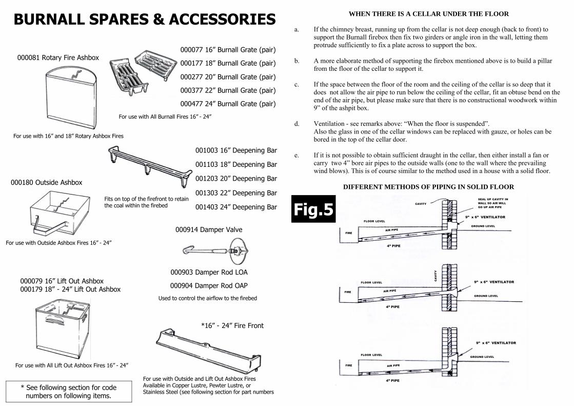
BURNALL SPARES & ACCESSORIES
000081 Rotary Fire Ashbox
For use with 16” and 18” Rotary Ashbox Fires
For use with All Lift Out Ashbox Fires 16” - 24”
000079 16” Lift Out Ashbox 000179 18” - 24” Lift Out Ashbox
000180 Outside Ashbox
For use with Outside Ashbox Fires 16” - 24”
For use with All Burnall Fires 16” - 24”
000077 16” Burnall Grate (pair)
000177 18” Burnall Grate (pair)
000377 22” Burnall Grate (pair)
000277 20” Burnall Grate (pair)
000477 24” Burnall Grate (pair)
000914 Damper Valve
000903 Damper Rod LOA
000904 Damper Rod OAP
Used to control the airflow to the firebed
Fits on top of the firefront to retain the coal within the firebed
001003 16” Deepening Bar
001103 18” Deepening Bar
001303 22” Deepening Bar
001203 20” Deepening Bar
001403 24” Deepening Bar
For use with Outside and Lift Out Ashbox Fires Available in Copper Lustre, Pewter Lustre, or Stainless Steel (see following section for part numbers
*16” - 24” Fire Front
* See following section for code numbers on following items.
WHEN THERE IS A CELLAR UNDER THE FLOOR a. If the chimney breast, running up from the cellar is not deep enough (back to front) to
support the Burnall firebox then fix two girders or angle iron in the wall, letting them protrude sufficiently to fix a plate across to support the box.
b. A more elaborate method of supporting the firebox mentioned above is to build a pillar
from the floor of the cellar to support it. c. If the space between the floor of the room and the ceiling of the cellar is so deep that it
does not allow the air pipe to run below the ceiling of the cellar, fit an obtuse bend on the end of the air pipe, but please make sure that there is no constructional woodwork within 9” of the ashpit box.
d. Ventilation - see remarks above: “When the floor is suspended”. Also the glass in one of the cellar windows can be replaced with gauze, or holes can be bored in the top of the cellar door. e. If it is not possible to obtain sufficient draught in the cellar, then either install a fan or carry two 4” bore air pipes to the outside walls (one to the wall where the prevailing wind blows). This is of course similar to the method used in a house with a solid floor.
DIFFERENT METHODS OF PIPING IN SOLID FLOOR
Fig.5 SEAL UP CAVITY IN WALL SO AIR WILL GO UP AIR PIPE
9” x 6” VENTILATOR
GROUND LEVEL
GROUND LEVEL
9” x 6” VENTILATOR
9” x 6” VENTILATOR
GROUND LEVEL
FIRE
FIRE
FIRE
FLOOR LEVEL
FLOOR LEVEL
FLOOR LEVEL
CAVITY
CA
VIT
Y
4” PIPE
4” PIPE
4” PIPE
AIR PIPE
AIR PIPE
AIR PIPE

FIXING THE BURNALL THE RECOMMENDED FIXING POSITION FOR A BURNALL FIRE IS TO HAVE THE FIRE SET FORWARD 2½” INTO THE HEARTH, SEE FIG 7A. THIS NOT ONLY ENHANCES THE LOOK OF THE FIREPLACE BUT ALSO INCREASES THE ARC OF RADIANT HEAT FROM THE FIRE. UNFORTUNATELY WHERE A FIREPLACE ALREADY EXISTS IT IS NOT ALWAYS A D-VISABLE TO RISK DAMAGING THE TILES BY CUTTING OUT THE HEARTH IN O R-DER TO BRING THE FIRE FORWARD. TO OVERCOME THIS DIFFICULTY THE BUR-NALL FIRE MAY BE FIXED BEYOND THE TILED HEARTH. SEE FIG 7B. THIS METHOD OF INSTALLATION REQUIRES THE FIRE TO BE FIXED WITH THE S PECIAL “EXTENDED SIDECHEEKS” WHICH ARE SUPPLIED ONLY ON REQUEST. BEFORE COMMENCING INSTALLATION DETERMINE THE TYPE OF SIDECHEEKS THAT ARE BEING FITTED. THE “EXTENDED SIDECHEEKS” ARE RECOGNIZED BY THE INCREASE IN SIZE (SEE FIG. 7) AND BY THE RECESS ON THE FRONT FACE TO ACCOMODATE THE FIRE FRONT. ENSURE THE INSTALLATION PROCEDURE APPROPRIATE TO THE TYPE OF CHEEK IS FOLLOWE D. THE “EXTENDED SIDECHEEKS” ARE NOT SUITABLE FOR INSTALLATIONS WITH BACK BOILERS UNLESS A MINIMUM BUILDERS OPENING DEPTH OF 16” FOR BURNALL PATENT BOILERS AND 17½” FOR BOILERS IS AVAILABLE. NOR ARE THEY SUITABLE FOR CONVECTOR SIDECHEEK INSTALLATIONS.
FIXING A NEW FIREPLACE WE SUGGEST USING A CONCRETE LINTEL OVER THE FIRE OPENING See fig. 6. and that the Builders opening to receive the fireplace be to British Standard C.P.403 (1952) for flush fireplace surrounds, 33” high x 23” wide, for both 16” and 18” fires.
INSTALLATION PROCEDURE 1. Break out any existing fireback. If an existing fireplace is being retained, leave the fireplace and hearth in position. Where a new fireplace is being fitted stand the new fireplace and hearth in their final positions. 2. a. With “Standard Sidecheeks.” Prepare the cut out in the hearth as follows. Measure 2½” forward on the hearth from the back of the return of the fire. Strike a line across this and mark a rectangle 2½” x ½” less than the given width of the fire, (i.e. for a 16” fire measure 15½”). See Fig. 7A. Remove the hearth where feasible and make the cut out as carefully as possible. An existing fireplace may be left in position. b. With “Extended Sidecheeks.” No cut out is required. Simply mark a line across the back of the return to fire. See Fig. 7B. An existing fireplace may be left in position.
FIXING BABY BRICKS IN PLACE OF A SECTIONAL FIREBACK
We supply two special kinds of baby brick, one with a round nose and the other with one side straight and side at an angle (bevelled). The round nosed (bullnosed) bricks are for near the sur-round. The straight side of both bricks is used for building the straight part of the back and sides and the angled side is used for building the forward sloping part of the back, making it look like an ordinary back. The brickwork must be bonded and should be built with fireclay with the joints pointed and as narrow as possible.
Fig.10
Baby Brick Firebacks are normally used only in place of STANDARD SIDECHEEKS, i.e. fires installed with a hearth cut out. If used in place of EXTENDED SIDECHEEKS the Baby Bricks require shaping in order to house the ends of the fire front. This can be done by using half bricks (bull nosed) to commence the first three rows of each of the two sidecheeks. The hearth bricks should be set at 90º to the fireplace opening. Thereafter the Baby Bricks should be angled so that the completed brickwork finishes level with the inside edge of the basket at the back. See fig. 10.
BRICKS BONDED
PART BRICK PART BRICK
ROUND NOSE BRICKS
EXTRA HALF BRICK REQUIRED WHEN FITTING IN PLACE OF EXTENDED SIDECHEEKS (FIRST 3 ROWS ONLY AT 90º
SHOWING BRICKS SITTING ON IRON BASKET
CO
NC
RE
TE
5 BRICKS
5/6 BRICKS

FIXING A BACK BOILER TO A BURNALL FIRE IF A BURNALL PATENT BOILER OR SELF CONTAINED FLUE SET IS USED. We do not intend to give full details of fixing block boilers as the tradesmen will be all too familiar with them, but only to mention special points when applied to a Burnall Fire.
Standard Sidecheeks should be used. A block boiler should be 1” forward into the fire. The size of the boiler flue should be: Under the boiler: 2” HIGH BY AT LEAST 5” WIDE. Behind the boiler: 2” DEEP BY THE WIDTH OF THE BOILER (fig. 9.) If the installation is to an existing fireplace which pre-viously had a raised fire, the boiler should be lowered accordingly for the Burnall Fire. POINTS TO WATCH: Pipes must be connected up correctly to the boiler - flow from and return to the boiler. The pipes must run in parallel lines, rising up to the cylinder. Sharp elbows must not be used. There should be a rise of at least 1” to 10” in the pipes from the boiler to the cylinder. The pipes must not run through a cavity wall or they will cool off quickly. We recommend that pipes and cylinders are lagged to retain heat.
Fig.9
3 4
2” MIN
BOILER TO BE 1” FORWARD OVER BURNALL BASKET
MINIMUM WIDTH 5”
BOILER SITS ON TWO FIREBRICKS 2” HIGH
BRICK BUILT FLUE
Fig.6 3. Dig out the hole for the Burnall Fire. See Fig.6. This should measure 14” deep from the top of the hearth level by the width of the fire opening. For back to front measurements:- a. With “Standard Sidecheeks” Measure 12” backwards from the line of the back of the return to fire and 4” forward of this line. If you have been unable to remove an existing hearth the forward measurement may be left at 2½” only. b. With “Extended Sidecheeks” Measure approximately 13½” backwards from the line of the back of the return. When digging out the hole for this installation slightly increase the back to front measurement towards the bottom of the pit by digging forward under the hearth about 1”.
4. 1½” from the bottom of the hole, in the centre, cut a 4” wide channel for the air pipe through the brick fender. See fig. 6. This can be made easier by cutting part way through the other side of the fender (see 5 below). 5. If there is no manhole in the floor of the house, cut out a small manhole to the front of the fender to allow the 2 ft. length of air pipe to be correctly fitted, making sure the end of the inlet pipe comes below the joist. 6. Bed the Burnall fire on 1½” of sand and cement with the front edge of the basket:- a. When fitted with “Standard Sidecheeks” 2” in front of the back of the return to fire. b. When fitted with “Extended Sidecheeks” ½” behind the back of the return to fire Replace the fireplace and hearth as necessary and check with a spirit level that THE TOP OF THE BASKET IS LEVEL WITH THE TOP OF THE HEARTH AND LEVEL BACK TO FRONT AND THAT IS IN THE CENTRE OF THE OPENING. See figs. 1 and 7.
PRECAST CONCRETE LINTEL
BACK OF RETURN OF FIRE
FIRE OPENING MAX
22”
HEARTH LEVEL
CUT OUT TO TAKE PIPE
BRICK FENDER
JOIST
MAN HOLE
4”
16”
1½”
14”
PIT TO TAKE BURNALL FIRE
12” OR 13½
4” MIN
4½” MAX

Fig.7
(a) Standard Sidecheeks.
(b) Extended Sidecheeks.
7. Remove the basket, fix the plain end of the air pipe on the nozzle, making good the joint between them, also make good the brickwork of the fender. 8. Put the damper tube and rod in position and fill round box with weak mixture of concrete. The correct position of the rod can be found by temporarily placing the front in position. 9. Run fire cement round the base of the basket to make the joint on the box, and then re-fix the basket and fill round the back and sides of this with weak mixture of concrete. If using baby bricks for the fireback or fixing a back boiler, please see separate section on these. 10. Bed one side cheek in mortar making sure it is solid and in its correct position on the basket. As the same bottom brick is used for 16” and 18” fires, to get the side cheeks even, care must be taken to position the corrugations correctly so that the line of the bottom edge of the side cheek tapers from touching the outside of the pip on the basket at the front, to wards the inside edge of the basket at the back. see fig. 7. Put the bottom back brick in position so that the corrugation engages with the knuckles on the back edge of the side cheek - see fig. 7. Bed the other side cheek in solid with its knuckle engaged in the bottom back brick. Fill in behind the bottom brick and lower the top back brick on to the bottom back brick and fill in behind it.
KNUCKLE ENDS OF SIDECHEEKS ENGAGE IN BACK BRICK GROOVES
FIRECLAY SIDECHEEKS
PIPS ON BASKET
NON-COMBUSTIBLE ROPE TO TAKE UP EXPANSION
LINE OF BACK OF RETURN
SLAG WOOL PACKS AREA OF CUT-OUT
CUTOUT IN BASKET FOR LUG ON FRONT STRIP TO ENGAGE
SLAG WOOL PACKS 8½”
2½”
PIPS ON BASKET
NON COMBUSTIBLE ROPE TO
TAKE UP EXPANSION
LINE OF BACK OF RETURN
SLAG WOOL PACKS
11”
KNUCKLE ENDS OF SIDECHEEKS ENGAGE IN BACK BRICK GROOVES
CUTOUT IN BASKET FOR LUG ON FRONT STRIP TO ENGAGE
TO ALLOW FOR EXPANSION OF THE SIDE CHEEKS NON COMBUSTIBLE ROPE SHOULD BE PLACED BETWEEN THE SIDE CHEEKS AND THE SURROUND (see fi g. 7.) Please note we cannot guarantee the firebricks, but if they are built in solidly there is less chance of their cracking. Also, please commence using the fire by having small fires only.
11. Carefully build up the chimney throat as is shown in fig. 6. taking care that it has a smooth finish and is gradually tapered.
12. Insert the slag wool pads in the ½” gap
left between the front of the basket and hearth, these are to allow for expansion of the fire (see fig. 7).
13. Remove the damper rod. Place the
front in position so that the two pips on it engage the basket, and it rests on the hearth. Place the damper valve in position from inside the fire (fig. 8), feed the damper rod into it and tighten the thumb screw. Turn the damper rod round to ensure it is not fouled by cement.
14. Seal all joints with plastic fire cement, that is. the joints of the fireback and the JOINT BETWEEN THE BASKET AND CAST IRON F IRE BOX.
Fig.8
CORRECT WAY TO HOLD DAMPER VALVE WHEN PLACING IT INTO THE NOZZLE FROM INSIDE THE BOX