For the Bridgeport V1000 - Megastream Apps Introduces...
131
V1000 Technical Sales Manual Hardinge Inc. 2015 Page 1 Guard doors may be shown open for clarity – Specifications are subject to change without notice TECHNICAL INFORMATION For the Bridgeport V1000 CNC Vertical Machining Centers
Transcript of For the Bridgeport V1000 - Megastream Apps Introduces...
V1000 Technical Sales Manual
Hardinge Inc. 2015 Page 1
Guard doors may be shown open for clarity – Specifications are subject to change without notice
TECHNICAL INFORMATION
For the
Bridgeport V1000 CNC Vertical Machining Centers

V1000 Technical Sales Manual
Hardinge Inc. 2015 Page 2
Guard doors may be shown open for clarity – Specifications are subject to change without notice
Contents
1. MACHINE CONFIGURATION
1‐1. General 1‐2. Standard Machine Features 1‐3. Machine Construction
1‐3.1. Cast Iron Base 1‐3.2. Cast Iron Vertical Column 1‐3.3. Cast Iron Headstock 1‐3.4. Saddle and Table Assembly
1‐4 Design Optimization 1‐5 Coolant Guard And Sheet Metal Enclosure
1‐5.1 Coolant Guard Door Safety
1‐6 Work Lights 1‐7 Status Stack Light 1‐8 Ease of Maintenance 1‐9 World Safety Standard

V1000 Technical Sales Manual
Hardinge Inc. 2015 Page 3
Guard doors may be shown open for clarity – Specifications are subject to change without notice
Contents
2. SPINDLE AND HEADSTOCK ASSEMBLY 2‐1 ISO‐40 Dual Contact Taper Spindle Configuration
2‐1.1 Spindle Bearing Configuration 2‐1.2 Headstock (Z‐Axis) Travel Specifications 2‐1.3 “V” Flange Tooling (Retention Knob Style) 2‐1.4 Tool Release 2‐1.5 Draw Bar 2‐1.6 Air Blast System
2‐2 AC Digital Direct Drive Spindle
2‐2.1 10,000 RPM Spindle Power and Torque Curves 2‐2.2 12,000 RPM Spindle Power and Torque Curves 2‐2.3 15,000 RPM Spindle Power and Torque Curves
2‐3 Encoder Arrangement 2‐4 Cutter Air Blast Option 2‐5 Thru Spindle Coolant Option

V1000 Technical Sales Manual
Hardinge Inc. 2015 Page 4
Guard doors may be shown open for clarity – Specifications are subject to change without notice
Contents
3. WORK TABLE AND LINEAR GUIDEWAYS
3‐1 Work Table ( X and Y Axis) 3‐1.1 Travel Specifications 3‐1.2 Table Dimensions and T Slot Locations
3‐2 Heavy Duty Linear Ways (All Axes) 3‐2.1 X Axis Linear Guideways 3‐2.2 Y Axis Linear Guideways 3‐2.3 Z Axis Linear Guideways
3‐3 Axis Ball Screws 3‐4 Axis Drive Systems 3‐5 Lubrication System
3‐5.1 Optional Automatic Grease Lubrication System
3‐6 Air Control Assembly 3‐7 Coolant System and Chip Management
3‐7.1 Coolant Pump 3‐7.2 Coolant Tank 3‐7.3 Coolant Nozzles and Flush
3‐8 Work Light

V1000 Technical Sales Manual
Hardinge Inc. 2015 Page 5
Guard doors may be shown open for clarity – Specifications are subject to change without notice
Contents
4. AUTOMATIC TOOL CHANGER (ATC)
4‐1 Swing Arm Type Tool Changer 4‐2 Automatic Tool Changer Illustrations 4‐3 Automatic Tool Changer Arm 4‐4 Automatic Tool Changer Pot\Chain
5. MACHINING CAPABILITES AND ACCURACIES
5‐1 Machining Capabilities 5‐1.1 Heavy – Duty Machining 5‐1.2 Drilling 5‐1.3 Rigid Tapping 5‐1.4 High Speed Machining
5‐2 Machining Accuracies ISO 230‐2 Specifications
5‐2.1 Linear Displacement Accuracy 5‐2.2 Geometry Accuracy 5‐2.3 Contouring Performance (Ballbar)
5‐3 Circle Diamond Square

V1000 Technical Sales Manual
Hardinge Inc. 2015 Page 6
Guard doors may be shown open for clarity – Specifications are subject to change without notice
Contents
6. MITSUBISHI M70V CNC CONTROL SYSTEM
6‐1 Standard CNC Control Features 6‐2 Conversational Programming Navi‐Mill Feature 6‐3 Descriptions of Standard and Optional Control Features 6‐4 Communications Features 6‐5 Machine Power Case

V1000 Technical Sales Manual
Hardinge Inc. 2015 Page 7
Guard doors may be shown open for clarity – Specifications are subject to change without notice
Contents
7. OPTIONAL EQUIPMENT
7‐1 Thru Spindle Coolant, 280PSI 7‐2 Linear Scales (X,Y,Z Axes) Factory Installed Only 7‐3 Cutter Air Blast 7‐4 Tool Probe 7‐5 Part Probe 7‐6 Chip Conveyor
7‐6.1 Hinge Type 7‐6.2 Scrapper Type
7‐7 Front Auto Door 7‐8 Tool Magazine Auto Door 7‐9 Automatic Central Grease Lubrication 7‐10 Spindle Oil Chiller
8. FLOOR PLAN AND SPECIFICATIONS
8‐1 Floor Plan and Foundation Requirements 8‐1 Lubrication Requirements 8‐2 Power Requirements 8‐3 Air Requirements 8‐4 Power Case
9. MACHINE SPECIFICATIONS

V1000 Technical Sales Manual
Hardinge Inc. 2015 Page 8
Guard doors may be shown open for clarity – Specifications are subject to change without notice
Contents
10. ADDITIONAL PRODUCT SUPPORT INFORMATION
10‐1 Helpful Hints 10‐2 Standard Machine Documentation Package 10‐3 Sales and Marketing Documentation
Technical Sales Bullet Technical Service, Maintenance Bullet

V1000 Technical Sales Manual
Hardinge Inc. 2015 Page 9
Guard doors may be shown open for clarity – Specifications are subject to change without notice
Section 1 MACHINE CONFIGURATION

V1000 Technical Sales Manual
Hardinge Inc. 2015 Page 10
Guard doors may be shown open for clarity – Specifications are subject to change without notice
1 MACHINE CONFIGURATION 1‐1 General
The Bridgeport Conquest V1000 CNC vertical machining centers are designed for accuracy, speed and productivity. They are built to provide years of dependable machining on parts requiring consistent tolerances, tough to machine materials and fine surface finishes. The V1000 features and robust “C‐Frame” (fixed column) design on an extremely rigid cast iron base. Included as standard equipment are a 10,000‐rpm Direct Drive Spindle, 30 tool swing arm tool changer, linear guideways for all axis motions and a feature rich Mitsubishi M70V control. Along with 40” X, 24” Y and 24” Z axis travels allowing the V1000 to stand above all other machines in its class. With wide range of options to choose from, this makes the V1000 machines best in class and stand above all competitive machining centers worldwide. V1000 series vertical machining centers feature:‐
1 year warranty is offered on the machine
3 year warranty is offered on the control Higher end features have been designed into the V1000 machines, while streamlining overall cost to provide a very price competitive machine for the higher end market. Some of the key features which make the V1000 machines best in class are:
10,000‐rpm, 29Hp, Direct Drive, Big Plus Spindle technology
Feature rich Mitsubishi M70V control system (Fanuc compatible)
Mitsubishi Navi‐Mill conversational programming system
Fast rapid travels (1692‐ipm X and Y Axis, 1417‐ipm Z Axis)
Fast 30‐tool swing arm automatic tool changer
Heavy duty linear guideways, ballscrews and axis drives

V1000 Technical Sales Manual
Hardinge Inc. 2015 Page 11
Guard doors may be shown open for clarity – Specifications are subject to change without notice
Critical component areas are hand scrapped to insure maximum bearing contact area of surfaces in 20 locations
Extended tool life due to overall machine rigidity and weight
Faster spindle speeds/response times with Direct Drive spindle motor technology
Thru‐Spindle coolant, air blast and high pressure coolant systems are available to allow faster cutting (optional)
Unhindered chip flow due to streamlined way cover design and totally enclosed machine guarding.
Rigid tapping capability
Largest Axis travels in its class

V1000 Technical Sales Manual
Hardinge Inc. 2015 Page 12
Guard doors may be shown open for clarity – Specifications are subject to change without notice
1‐2 Standard Machine Features
ISO40 “V” flange Dual Contact taper spindle with a fully enclosed hardened and precision ground, pre‐loaded ball bearing design. A taper air blast system is utilized to minimize spindle contamination during tool changes. Additionally a low pressure air purge and labyrinth seal keep coolant out of the spindle bearings.
Cast iron headstock housing
Standard Direct Drive main spindle AC digital drive and motor delivers 20Hp (15KW) continuous rating, 29Hp (22KW) intermittent duty rating. Spindle belts are no longer required with the Direct Drive spindle technology resulting in less spindle vibrations, as well as fast acceleration and deceleration rates.
A pneumatic tool release mechanism with a double piston cylinder arrangement is utilized to actuate a spring loaded draw bar gripper system to release the tool from the spindle. Clamping force is 1,875Ft‐Lbs (8336N)
Heady duty cast iron base and column providing superior vibration dampening, structural rigidity and thermal stable machine necessary for obtaining precision tolerances and fine surface finishes. Total machine weight is 15,400Lbs (7000Kg), heaviest in its class.
30 tool capacity, swing arm automatic tool changer allows for extremely fast tool changes to further reduce cycle time. A “Big Tool” feature is also included as standard in the control to allow use of oversize tools without interference with adjacent pockets. Tool change time (tool to tool) is 1.5 seconds.
One button tool changer fault recovery feature is included to minimize downtime in the event of a tool changer fault.
Heavy duty 1.77” (45mm) diameter hardened and ground ball screws for X, Y and Z‐axis slide movements. Ball screws are driven by powerful direct axis drive servomotors and are totally enclosed by protective steel way covers.

V1000 Technical Sales Manual
Hardinge Inc. 2015 Page 13
Guard doors may be shown open for clarity – Specifications are subject to change without notice
Heavy duty linear guideways are used for all axis motion. X axis guideway size is 1.377” (35mm). Y and Z axis guideway size is 1.77” (45mm). Linear guideways allow less friction, less heat and less thermal growth when compared to conventional box way systems.
Absolute encoders are utilized on all axis to eliminate reference return procedures on power up
A centrally located manual grease lubrication system is featured for all sliding elements and ball screws to minimize coolant contamination and reduce waste oil removal costs.
Machine is completely enclosed by reinforced guarding allowing for chip and coolant containment while providing for safe operation. Main guard doors are also auto cycle interlocked.
Coolant system pump is rated at 34gpm (130lpm) flow rating. Quick disconnect coolant tank with 105Gal (400L) capacity. Large 3” (76.2mm) diameter casters permit the tank to be conveniently moved for cleaning.
Two work lights, one strip and one spot, for optimum operator visibility to machining envelope area.
Feature rich Mitsubishi M70V series control system, including the Navi‐Mill shop floor programming system.
30 Retention Knobs
6 Port Surround Tool Coolant
Air Hose with Air Gun
Leveling Pads and Bolts
Tool Kit
Complete machine/CNC unit documentation package, including manuals, parts list and wiring diagram

V1000 Technical Sales Manual
Hardinge Inc. 2015 Page 14
Guard doors may be shown open for clarity – Specifications are subject to change without notice
1‐3 Machine Construction The base is a one piece cast iron construction. The base is supported by seven adjustable legs: four of which are located directly below the load path of the vertical column. The bottom of the column is hand scrapped for flatness and perpendicularity to the Z axis linear guideways. The mating surface of the base is also hand scraped for flatness and squareness to the column. The result is an extremely rigid joint and absolute perpendicularity of the axes.

V1000 Technical Sales Manual
Hardinge Inc. 2015 Page 15
Guard doors may be shown open for clarity – Specifications are subject to change without notice
1‐3‐1 Cast Iron Base The base was designed using FEA (finite element analysis) techniques to provide superior machining performance. The result is a highly‐rigid base with optimum dynamic stability. The cast iron base weighs in at 5100 lbs (2314kg).
Base Construction

V1000 Technical Sales Manual
Hardinge Inc. 2015 Page 16
Guard doors may be shown open for clarity – Specifications are subject to change without notice
1‐3‐2 Cast Iron Vertical Column and Headstock The honey‐comb like reinforced‐rib radial and peripheral design provides optimum stiffness with minimum weight for proper stiffness to weight ratio. Unlike competitors who use thicker walls and higher weights in their castings that create increased mass and decreased frequency, the Hardinge design provides higher stiffness without increased mass. Higher frequency provides optimum machining capabilities. The ball screw mounts are designed to be recessed inside the casting for minimal overhang. This results in a highly rigid structure, increasing the overall rigidity of the machine.
Column Construction

V1000 Technical Sales Manual
Hardinge Inc. 2015 Page 17
Guard doors may be shown open for clarity – Specifications are subject to change without notice
1-3-3 Cast Iron Vertical Column and Headstock
The headstock casting is symmetrically designed about the Y and Z axis plane for proper weight balance and heat distribution. The affect of spindle nose offset and consequent binding loads are minimized by recessed ball screws in the vertical column and the use of three pairs of trucks on the Z axis.
Headstock Housing

V1000 Technical Sales Manual
Hardinge Inc. 2015 Page 18
Guard doors may be shown open for clarity – Specifications are subject to change without notice
1‐3‐4 Saddle and Table Assembly
The machine design incorporates wide spacing between the guideways for higher overall stiffness with minimal overhangs, for better distribution of cutting forces. A low center of gravity assists in the reduction of vibrations due to cutting forces.
Base, Saddle and Table

V1000 Technical Sales Manual
Hardinge Inc. 2015 Page 19
Guard doors may be shown open for clarity – Specifications are subject to change without notice
1‐3‐4 Saddle and Table Assembly (continued)
Base, Saddle and Table (Front View)
Base, Saddle and Table (Side View)

V1000 Technical Sales Manual
Hardinge Inc. 2015 Page 20
Guard doors may be shown open for clarity – Specifications are subject to change without notice
1‐4 Design Optimization
Design of all major structural components of the Conquest V1000 is based on extensive analyses to assure optimum rigidity and fatigue life. Subsystems requiring precise dynamic motions and timing have been tested exclusively for endurance. These include the ATC (Automatic Tool Changer) and draw bar actuator mechanisms. State of the art finite element analyses (FEA) were used to optimize the design of individual major castings – base, saddle, vertical column and headstock – as well as the overall V1000 structure to provide the rigidity and stiffness in the cutting zone for consistent geometric tolerances and surface finishes. An interactive design process was used to successfully improve the reference design based on the results of detailed static and dynamic analyses. The final outcome is rigid, structurally balanced design with optimum strength to weight ratios for the major castings and the following key features:
• Seven (7) feet supporting the base for a highly stable and efficient
load distribution without warping and twisting.
• Structural ribbing and gusseting of castings to significantly
increase static and dynamic stiffness with minimal weight
increase.
• Deep, recessed ball screw mounts to minimize centerline
offsets resulting in lower bending and torsional loads to the
linear guide surfaces.
• Optimally‐located, highly rigid base‐to‐column joint, providing for excellent squareness and flatness.
V1000 Technical Sales Manual
Hardinge Inc. 2015 Page 21
Guard doors may be shown open for clarity – Specifications are subject to change without notice
1‐4 Design Optimization (continued)
• Heavy‐duty ball screws, linear guides, bearings and bearing
supports for high stiffness and long fatigue life. On the vertical Z‐
axis column, the ball screw is provided with a triplex support
bearing and the linear guides include three (3) pair of trucks.
• ATC frame design with good stiffness to support the full dynamic
loading of the tool changer, yet provide the required modal
separation (widely spaced dynamic frequencies) relative to the
main machine structure. The stiffness provides for maintaining
the close alignment for tool changer arm for excellent reliability
and wear life, while the modal separation assures that the
dynamic response of the ATC has no adverse impact on the
machine's cutting performance.

V1000 Technical Sales Manual
Hardinge Inc. 2015 Page 22
Guard doors may be shown open for clarity – Specifications are subject to change without notice
1‐4 Design Optimization (continued)
Heavily ribbed cast iron construction engineered for excellent overall stiffness and rigidity.
V1000 Technical Sales Manual
Hardinge Inc. 2015 Page 23
Guard doors may be shown open for clarity – Specifications are subject to change without notice
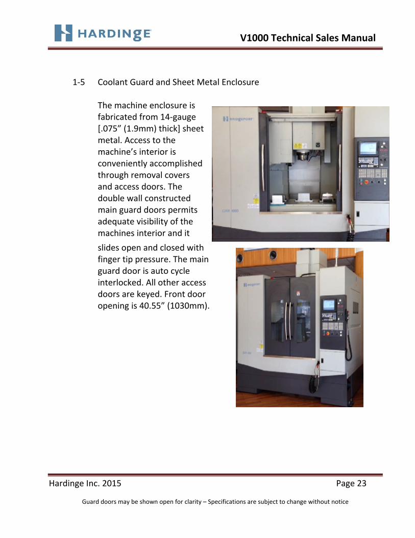
1‐5 Coolant Guard and Sheet Metal Enclosure The machine enclosure is fabricated from 14‐gauge [.075” (1.9mm) thick] sheet metal. Access to the machine’s interior is conveniently accomplished through removal covers and access doors. The double wall constructed main guard doors permits adequate visibility of the machines interior and it
slides open and closed with finger tip pressure. The main guard door is auto cycle interlocked. All other access doors are keyed. Front door opening is 40.55” (1030mm).

V1000 Technical Sales Manual
Hardinge Inc. 2015 Page 24
Guard doors may be shown open for clarity – Specifications are subject to change without notice
1‐5‐1 Coolant Guard Door Safety
Door Safety
Front Door Thickness / Window
Front Door Stays Intact
Switches and Tamperproof Hardware

V1000 Technical Sales Manual
Hardinge Inc. 2015 Page 25
Guard doors may be shown open for clarity – Specifications are subject to change without notice
1‐6 Work Lights A single tube style LED work light is located above the machining area inside the machine to provide adequate light to this area. Additionally there is a single positional spot light for pin point focusing.
1‐7 Machining Status Stack Light
Mounted to the top of the CNC control support structure is a 3 position machining status stack light to determine the machines operating status. Mounted in this area the status of the machine can be determined from a greater distance when compared to a flush mount style status light.

V1000 Technical Sales Manual
Hardinge Inc. 2015 Page 26
Guard doors may be shown open for clarity – Specifications are subject to change without notice
1‐8 Ease of Maintenance Maintenance was a major criteria while designing the V1000 machine. So as to provide our customers with minimal downtime in the event service is required, pressure monitoring sensors have been built into the machines pneumatic and control systems for ease in troubleshooting a problem. Circuit breakers and fuse blocks are also incorporated. All critical components, including spindle bearings, ball bearing, support bearings, linear guideways, ballscrews, spindle and axis servomotors and drives, were designed and built to provide years of trouble free service. Coolant and lubrication systems have been sized with large capacities to reduce maintenance downtime.

V1000 Technical Sales Manual
Hardinge Inc. 2015 Page 27
Guard doors may be shown open for clarity – Specifications are subject to change without notice
1‐9 World Safety Standard
Operator safety is a top priority of Hardinge that also begins in the design stages of the machine tool and Hardinge has taken a proactive stance to be a world leader in this area. The V1000 machine incorporates the latest in the Hardinge World Safety Standards. This requires that all operator accessible doors be verified upon power up to ensure they are working correctly, it also allows spindle rotation speed of less than 50rpm, axes travel speed of no more than 2000mm/min. and tool changer motions stop immediately while the main guard door is open. Additionally once any operator accessible door is opened the machine is placed in shut down condition to ensure safety of any persons working within the machine enclosure. The noise level specification is 71.3 dB(A).
LATEST US AND CE SAFETY STANDARDS • Directives: 2006/42/EC (Machinery Directive)
2004/108/EC (EMC Directive) 2006/95/EC (Low Voltage Directive)
• BS EN 12417:2001+A2:2009 (Machine tools ‐Safety – Machining Centers)
• ANSI B11.22–2002 • NFPA 79:2007 • CSA: NA • UL: Would need to be reviewed by UL inspector. UL was not part
of the design criteria.

V1000 Technical Sales Manual
Hardinge Inc. 2015 Page 28
Guard doors may be shown open for clarity – Specifications are subject to change without notice
Section 2
SPINDLE & HEADSTOCK ASSEMBLY

V1000 Technical Sales Manual
Hardinge Inc. 2015 Page 29
Guard doors may be shown open for clarity – Specifications are subject to change without notice
2 Spindle & Headstock Assembly
2‐1 ISO‐40 Dual Contact BIG‐PLUS® Taper Spindle Configuration
ISO‐40 “V” flange Dual Contact taper spindle with a fully enclosed hardened and precision ground, pre‐loaded ball bearing design. A taper air blast system is utilized to minimize spindle contamination during tool changes. Additionally a low pressure air purge and labyrinth seal keep coolant out of the spindle bearings. CAT‐V‐40 flange tooling is available from Hardinge

V1000 Technical Sales Manual
Hardinge Inc. 2015 Page 30
Guard doors may be shown open for clarity – Specifications are subject to change without notice
2‐1 ISO‐40 Dual Contact Taper Spindle Configuration (continued)
The Dual Contact Taper spindle design is also known as BIG‐PLUS®. This design allows simultaneous face and taper contact when the tool is
clamped in the spindle. This system provides a stiffer interface between
the spindle and the tool holder along with minimizing run out on
extended tool and better overall rigidity.
The working principle of the BIG‐PLUS® (BCV/BBT) spindle, with a dual
contact type tool holder, is that before clamping, the tool holder taper
and spindle taper are in contact with each other to establish a good taper
fit, however face contact has not occurred. When the machine’s spindle
draw bar is activated, the tool holder is pulled into the machine’s spindle
which expands by elastic deformation until the faces of the spindle and
the tool holder contact each other. This completes the simultaneous fit
of the tool holder taper and flange to the spindle taper and face.

V1000 Technical Sales Manual
Hardinge Inc. 2015 Page 31
Guard doors may be shown open for clarity – Specifications are subject to change without notice
2‐1 ISO‐40 Dual Contact Taper Spindle Configuration (continued)
Key benefits:
Superior rigidity
Decreased tool deflection
Decreased vibration
Increased accuracy
Improved surface finish
Extended tool life

V1000 Technical Sales Manual
Hardinge Inc. 2015 Page 32
Guard doors may be shown open for clarity – Specifications are subject to change without notice
2‐1‐1 Spindle Bearing Configuration
This machine fitted with Direct-drive spindle provides fast acceleration and deceleration time, and equipped with double large O type bearings to increase rigidity. Bearing Classification Bearing dimensions and classifications are as follows: Ball Bearings – 110mm OD x 70mm ID x 20mm width x 4EA

V1000 Technical Sales Manual
Hardinge Inc. 2015 Page 33
Guard doors may be shown open for clarity – Specifications are subject to change without notice
A low pressure air purge system is combined with a labyrinth seal to protect the permanently lubricated spindle bearings from coolant ingress. Through spindle coolant and air blast options are available to help minimize chip build.
Drawing of labyrinth seal area
The spindle centerline reach is 42” (1066mm) from the front of the machine. This provides operator convenience when loading and unloading tools. The maximum tool weight in the spindle 15.4lbs (kg).
Labyrinth Shield

V1000 Technical Sales Manual
Hardinge Inc. 2015 Page 34
Guard doors may be shown open for clarity – Specifications are subject to change without notice
2‐1‐2 Headstock Z Axis Travel Specifications

V1000 Technical Sales Manual
Hardinge Inc. 2015 Page 35
Guard doors may be shown open for clarity – Specifications are subject to change without notice
2‐1‐3 “V’ Flange Tooling – Retention Knob Style
The base design of the Conquest V100 uses ANSI B5.50‐1985 (CAT‐V40)
“V” Flange taper spindle tooling. BIG‐PLUS® Dual Contact Taper tooling may be used and is recommended for heavy aggressive cutting, maximum rigidity for extended tool and for the best possible accuracy for tight tolerance finishing work.

V1000 Technical Sales Manual
Hardinge Inc. 2015 Page 36
Guard doors may be shown open for clarity – Specifications are subject to change without notice
2‐1‐4 Tool Release The tool release mechanism consists of a double‐piston cylinder
arrangement to actuate a spring‐loaded (disk springs) draw bar/gripper
mechanism. The load path is designed to isolate the spindle bearings from
all actuation (clamp and eject) forces. The air blast is used during tool
release in manual or automatic tool change (ATC) mode. The design
includes a safety interlock that disables the manual tool release in the
spindle‐run mode. Pneumatic actuation of tool release consists of two
stages. On initiation of a tool release signal, the cylinder is first
pressurized (to about 25 psi) to move up against the outer retaining nut. In
the second stage, the cylinder is pressurized to full pressure (70 to 90 psi)
in the opposite direction, causing a fast downward motion of the dual
pistons, the draw bar and retaining nut. The downward motion of the draw
bar moves the gripper fingers down from their radially constrained position
into the spindle counterbore area, allowing them to spread open from the
retention knob. Simultaneously, the bottom of the gripper physically
contacts the top of the retention knob and knocks it out (about 1.6 mm)
for a quick tool release.

V1000 Technical Sales Manual
Hardinge Inc. 2015 Page 37
Guard doors may be shown open for clarity – Specifications are subject to change without notice
2‐1‐5 Draw Bar Configuration The main components of the draw bar assembly include a draw bar, an annular spring pack and the retention know gripper unit. The outside diameter of the draw bar is hardened and ground for straightness to minimize vibrations in the clamp force due to stiction. The inside is hollow to allow for air blast during the tool change cycle, as well as thru spindle coolant (optional) by means of a rotary union. The draw interacts with the pneumatic actuator through a retaining nut at the top and the gripper unit for tool clamp and un‐clamp on the bottom. The spring pack consists of 84 Belville washer springs mounted in a back to back pair arrangement. The spring pack slips over the draw bar in the annular gap inside of the spindle cartridge. The spring pack is designed and preloaded to exacting dimensions to provide the specified clamp and ejection forces through the interaction of the draw bar with the pneumatic actuation. The outside diameter is carefully controlled to eliminate stiction with the spindle and maintain balance at high spindle speeds. The gripper unit consists of the gripper body and four (4) spring‐loaded gripper fingers. When radially unconstrained, the fingers are in the open (tool release) position under the spring load. When radially closed in the tool clamp position, the fingers provide nearly 100% wraparound against the retention know. This, unlike other designs such as balls and expanding collets, assures positive clamping with very high stiffness and virtually fatigue free operation. The fingers are hardened and ground to minimize wear and the inside and outside profiles are precisely contoured to match the retention knobs and spindle profile.

V1000 Technical Sales Manual
Hardinge Inc. 2015 Page 38
Guard doors may be shown open for clarity – Specifications are subject to change without notice
In the workpiece to load path, the weakest link is the tool holder to spindle interface. The finger design in the Conquest V1000 machine allows for a much higher retention know contact and clamping force, coupled with the Dual Contact Taper spindle design, provides a significantly stiffer joint. Specified force values are:
Clamping Force: 1,875 〜 2,096 ft‐lbs
8,336N 〜 9,316N
Ejection Force: 7,154 lbs/31,823 N Min @ 70 psi 8,585 lbs/38,187 N Max @ 90psi

V1000 Technical Sales Manual
Hardinge Inc. 2015 Page 39
Guard doors may be shown open for clarity – Specifications are subject to change without notice
2‐1‐6 Air Blast (Taper Cleaning) System
The tool release mechanism is designed to provide continuous air blast during a tool release in order to blow out and clean the spindle taper. The downward motion of the draw bar during tool release closes the annular gap in the cylinder at the top of the draw bar, forcing air through the draw tube. During automatic tool change under program control, the blast remains on during the full tool change cycle. In manual modem, the blast remains on as long as the tool release button is activated.
Manual Tool Release Button

V1000 Technical Sales Manual
Hardinge Inc. 2015 Page 40
Guard doors may be shown open for clarity – Specifications are subject to change without notice
2‐2 AC Digital Direct Drive Spindle
The AC digital spindle drive and motor are more accurate and responsive as compared to analog spindle drives, motors and belts. The motor is more reliable and requires minimal maintenance, since air cooled, brushless, permanently sealed and lubricated. The V1000 machine features a Mitsubishi hollow shaft spindle motor which delivers 20Hp (15Kw) continuous rating. The standard hollow shaft motor allows for easy installation of optional High Pressure Through Spindle Coolant. The drive and motor offer a spindle speed range of 35 to 10,000 rpm with speeds fully programmable in one‐rpm increments. The continuous torque rating is 75.2ft‐lbs (102 Nm) at a base speed of 1400 rpm. Optional 12,000 and 15,000 rpm spindles are available as options, both spindles feature oil\air lubrication resulting in extended spindle life. An optional spindle chiller is also available and is included with the 12,000 or 15,000 rpm spindle options.
Spindle Chiller 12k & 15K RPM Oil\Air Unit

V1000 Technical Sales Manual
Hardinge Inc. 2015 Page 41
Guard doors may be shown open for clarity – Specifications are subject to change without notice
2‐2‐1 10,000 RPM Spindle Power and Torque Curves
10,000 Spindle Power Curve

V1000 Technical Sales Manual
Hardinge Inc. 2015 Page 42
Guard doors may be shown open for clarity – Specifications are subject to change without notice
2‐2‐2 12,000 RPM Spindle Option Power and Torque Curves
12,000 RPM Spindle Option Power Curve

V1000 Technical Sales Manual
Hardinge Inc. 2015 Page 43
Guard doors may be shown open for clarity – Specifications are subject to change without notice
2‐2‐3 15,000 RPM Spindle Option Power and Torques Curves
15,000 RPM Spindle Option Power Curves

V1000 Technical Sales Manual
Hardinge Inc. 2015 Page 44
Guard doors may be shown open for clarity – Specifications are subject to change without notice
2‐3 Spindle Encoder Arrangement
An encoder is built into the spindle drive motor for spindle position
feedback to provide proper orientation of the spindle for tool change.
The encoder also maintains a revolution count for rigid tapping by
synchronizing speeds and feeds to assure a proper thread lead is
maintained.
2‐4 Cutter Air Blast System Option
The Cutter Air Blast option is located on the headstock frame on the right side of the spindle and delivers up to 80psi (5.5Bar) force of air from the standard machine air supply. It is useful for evacuating chips from the workholding device in automated operations and may also be used for dry machining applications.
2‐5 High Pressure 1000psi (70bar)Thru Spindle Coolant Option The Thru Spindle Coolant feature provides improved chip evacuation, tool life and cutting performance during deep hole drilling applications and when utilizing high performance cutting tools with coolant feed tool holders. The hollow shaft motor allows for easy installation of the optional High Pressure Coolant.
V1000 Technical Sales Manual
Hardinge Inc. 2015 Page 45
Guard doors may be shown open for clarity – Specifications are subject to change without notice
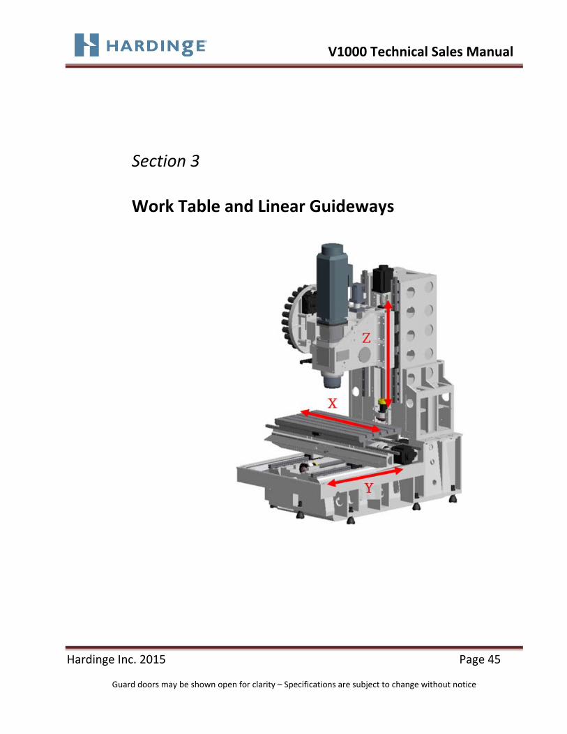
Section 3 Work Table and Linear Guideways

V1000 Technical Sales Manual
Hardinge Inc. 2015 Page 46
Guard doors may be shown open for clarity – Specifications are subject to change without notice
3 Work Table and Linear Guideways
3‐1 Work Table (X and Y Axis)
The Conquest V1000 features an oversized table (47.2”/1200mm x 23.6”/600mm) for this size machining center. Five T‐slots are used on the V1000 as compared to three that are used on most other competitive machine with a similar sized travel. The added T‐slots provide increased flexibility for work holding devices. The maximum table weight is 2,000lbs (900kg) when centered on the table. The T‐slot size is .708” (18mm). Pitch, or center to center distance, from T‐slot to T‐slot is 3.93” (100mm).

V1000 Technical Sales Manual
Hardinge Inc. 2015 Page 47
Guard doors may be shown open for clarity – Specifications are subject to change without notice
3‐1‐1 Travel Specifications

V1000 Technical Sales Manual
Hardinge Inc. 2015 Page 48
Guard doors may be shown open for clarity – Specifications are subject to change without notice
3‐1‐1 Travel Specifications (continued)

V1000 Technical Sales Manual
Hardinge Inc. 2015 Page 49
Guard doors may be shown open for clarity – Specifications are subject to change without notice
3‐1‐2 Table Dimensions and T‐slot Locations

V1000 Technical Sales Manual
Hardinge Inc. 2015 Page 50
Guard doors may be shown open for clarity – Specifications are subject to change without notice
3‐2 Heavy Duty Linear Guideways
All X, Y (Table) and Z‐axis (Headstock) movements are accomplished on heavy‐duty linear guideways. This approach to axial movement produces less friction, less heat, and less machine growth compared to friction slides (box ways). The result is faster traverse rates for reduced cycle times, less machine wear, longer machine life, and greater positioning for overall machining consistency. Movement is accomplished with ball screws on the X, Y, and Z‐axis. The linear modules consist of slide members (guide trucks) and linear rails to provide large load rating, stable accuracy, high rigidity and low friction. The spacing between the rails provides optimum stiffness for the overall machine design. Lubrication is provided to the trucks with centrally located manual grease system. . Ball Groove Design
The linear recirculating ball bearing and guideway assemblies (X, Z and Y) are preloaded to provide stiff and rigid system. Their low friction characteristics allow very high accelerations and velocities. The illustration below shows that the upper and lower ball rows have a contact angle of 45 degree and carry comprehensive, tensile and lateral loads.

V1000 Technical Sales Manual
Hardinge Inc. 2015 Page 51
Guard doors may be shown open for clarity – Specifications are subject to change without notice
3‐2 Heavy Duty Linear Guideways (continued)

V1000 Technical Sales Manual
Hardinge Inc. 2015 Page 52
Guard doors may be shown open for clarity – Specifications are subject to change without notice
3‐2‐1 X Axis Linear Guideways
The X axis features (2) HIWIN 35mm ball guide rails with (2) trucks per guideway rail.
X Axis Guideway System

V1000 Technical Sales Manual
Hardinge Inc. 2015 Page 53
Guard doors may be shown open for clarity – Specifications are subject to change without notice
3‐2‐2 Y Axis Heavy Duty Linear Guideways
The Y axis features (2) HIWIN 45mm ball guide rails with (2) trucks per guideway rail.
Y Axis Guideway System

V1000 Technical Sales Manual
Hardinge Inc. 2015 Page 54
Guard doors may be shown open for clarity – Specifications are subject to change without notice
3‐2‐3 Z Axis Heavy Duty Linear Guideways
The Z axis features (2) HIWIN 45mm ball guide rails with (3) trucks per guideway rail.
Z Axis Guideway System Wedges are used to hold the linear rails securely in position during manufacturing. Unlike some competitive machines where the builder removes the wedges after construction, Hardinge leaves the wedges in position to provide maximum rail stability in the event of a crash.

V1000 Technical Sales Manual
Hardinge Inc. 2015 Page 55
Guard doors may be shown open for clarity – Specifications are subject to change without notice
3‐3 Axis Ball Screws
The 1.77” (45mm) diameter x 12mm pitch ball screws feature a single‐flange, double‐ball nut arrangement (preloaded with spacer). With this arrangement, one nut takes the load in one direction and the other nut takes the load in the opposite direction. The opposing reaction‐load of the balls in the nuts converge toward the common center of the screw. Preloading is increased by increasing the thickness of the spacer between the nuts. The ball screw is also grease lubricated.
Fixed, pre‐tensioned (.04mm) ballscrews minimize thermal growth,
enhance rigidity, stability and overall machine precision. Each axis
features (5) bearings total per ballscrew, (3) bearing set on the motor
side and a 2 bearing set on the opposite end.
X and Y axis rapid travel rates are 1,692 ipm (43m/min). Z axis rapid
travel rate is 1,417 ipm (36m/min). Minimum and maximum feed rate
travels are .1 – 629 ipm (.00255 – 16m/min) for all axes.

V1000 Technical Sales Manual
Hardinge Inc. 2015 Page 56
Guard doors may be shown open for clarity – Specifications are subject to change without notice
3‐3 Axis Ball Screws (continued)
The X, Y and Z Axis ballscrews are HIWIN Class #3 1.771” (45mm)
diameter, .472” (12mm) pitch utilizing double ball nuts.
Z Axis Shown

V1000 Technical Sales Manual
Hardinge Inc. 2015 Page 57
Guard doors may be shown open for clarity – Specifications are subject to change without notice
3‐4 Axis Drive System
The use of direct drive AC digital drive servo motors are used on all axes.
The result is improved axes reliability, since the need for timing belts and
pulleys are eliminated. Mitsubishi 4 hp (3.0kW) 3000 rpm servo motors
are utilized on the X and Y axis. Mitsubishi 6 hp (4.5kW) 3500 rpm servo
motor is utilized on the Z axis. All servo motors incorporate absolute
encoders that do not require zero returning off the machine on power up
and are direct coupled to provide a rigid, positive drive system without
loss of positioning.
The couplings allow bending flexibility and compensation for any potential
parallel and/or angular misalignment between the drive motor and the
ballscrew.
All Mitsubishi servo motors include the Collision Detection feature which
senses an overload condition and shuts off the servos to help protect each
axis in the event of a collision.

V1000 Technical Sales Manual
Hardinge Inc. 2015 Page 58
Guard doors may be shown open for clarity – Specifications are subject to change without notice
3‐5 Lubrication System
The Conquest V1000 machines utilize a centrally located manual grease
system for all ballscrew and linear guideways for extended life. Grease
lubrication systems also offer the following advantages over way lube oil
systems.
No oil skimmer required
No degradation of water‐based coolants due to contamination
Environmentally friendly – no need to dispose of contaminated oil
The system should be greased every 6 months or approximately 400
hours of machine, this should occur more frequently under severe
operating conditions. A timer in the control issues a “lubrication alarm”
very 400 hours of operation.
Centralized Manual Grease Lubrication System

V1000 Technical Sales Manual
Hardinge Inc. 2015 Page 59
Guard doors may be shown open for clarity – Specifications are subject to change without notice
3‐5‐1 Optional Automatic Grease Lubrication System
An optional Automatic Grease Lubrication System is also available. A Low
grease alarm will be generated to alert the operator when the grease
reservoir for the system requires replenishing. The low lubrication alarm
cannot be deactivated until the lubrication unit level has been
replenished to a sufficient amount. The low lubrication alarm will not be
generated until the end of the machining cycle to minimize tool damage.
Optional Automatic Grease Lubrication System

V1000 Technical Sales Manual
Hardinge Inc. 2015 Page 60
Guard doors may be shown open for clarity – Specifications are subject to change without notice
3‐6 Air Control Assembly
Air supplied to the machine passes through a filter/regulator to set the
air pressure and remove contaminants from the machine air supply.
Recommended compressed air requirement is 90 psi, air consumption is
23 scfm.
The air control assembly
distributes air to the following
areas:
Spindle Air Purge
System
Spindle Taper Air
Blast
Activation of the tool
release system
It is recommended that a heavy
duty air dryer be added to the
incoming line if excessive
moisture is present in the system.
Air Control Assembly

V1000 Technical Sales Manual
Hardinge Inc. 2015 Page 61
Guard doors may be shown open for clarity – Specifications are subject to change without notice
3‐7 Coolant System and Chip Management
Water or oil based coolants may be used. On\off control if coolant
through the program is via M Codes. The ergonomically designed, heavy
gauge sheet metal enclosure, steel way covers and coolant flush system
ensures coolant and chip containment while providing effective ship
evacuation for a clean working environment.

V1000 Technical Sales Manual
Hardinge Inc. 2015 Page 62
Guard doors may be shown open for clarity – Specifications are subject to change without notice
3‐7‐1 Coolant Pump
The standard coolant pump is rated at a 34 gpm (130lpm) flow rate.
Coolant tank capacity is 105 gal (400L).
Through spindle coolant option up to 1000 psi (70bar) is also available.
3‐7‐2 Coolant Tank System
The coolant tank system comprises two separate coolant tanks. One of
which is located on the left side of the machine and house the pump and
float level systems and the main tank which is located under the front of
the machine. The left side tank is easily accessible for maintenance while
the front tank is removable and mounted on casters. The front tank also
allows use of the optional chip conveyor system. The chip conveyor
system may be mounted to exit out the right or left hand side of the
machine.

V1000 Technical Sales Manual
Hardinge Inc. 2015 Page 63
Guard doors may be shown open for clarity – Specifications are subject to change without notice
3‐7‐2 Coolant Tank System (continued)
Left Side Coolant Tank
Front Coolant Tank

V1000 Technical Sales Manual
Hardinge Inc. 2015 Page 64
Guard doors may be shown open for clarity – Specifications are subject to change without notice
3‐7‐3 Coolant Nozzles and Flush Features
There are (6) six surround tool coolant ports standard which surround
the spindle of the machine.
Surround Tool Coolant Ports
A coolant wash down nozzle and hose are also included as standard.
Coolant Wash Down Nozzle

V1000 Technical Sales Manual
Hardinge Inc. 2015 Page 65
Guard doors may be shown open for clarity – Specifications are subject to change without notice
3‐8 Work Lights
A single tube style LED work light is located above the machining area
inside the machine to provide adequate light to this area. Additionally there is a
single positional spot light for pin point focusing

V1000 Technical Sales Manual
Hardinge Inc. 2015 Page 66
Guard doors may be shown open for clarity – Specifications are subject to change without notice
Section 4
Automatic Tool Changer (ATC)

V1000 Technical Sales Manual
Hardinge Inc. 2015 Page 67
Guard doors may be shown open for clarity – Specifications are subject to change without notice
4 Automatic Tool Changer (ATC) 4‐1 Swing Arm Type Tool Changer
The random, bi‐directional tool changer features a double‐grip, swing arm design that provides positive gripping to interchange tools in a single move (tools lock into position in the event of power interrupt). Fast tool to tool change time of 1.5 seconds and chip to chip time of 4 seconds are provided. Maximum tool weight is 15 lbs (7kg), maximum tool diameter with adjacent tools is 2.95” (75mm) and maximum length is 11.82” (300mm) as measured from the gauge line of the tool. A big tool function is standard on the control allowing use of up to four big tools with a maximum diameter of 5.9” (150mm) & with adjacent tool is 2.95” (75mm) and maximum length is 11.82” (300mm).
Swing Arm Tool Changer Mechanism

V1000 Technical Sales Manual
Hardinge Inc. 2015 Page 68
Guard doors may be shown open for clarity – Specifications are subject to change without notice
4‐1 Swing Arm Type Tool Changer (continued) There are thirty (30) tool pockets in the chain and one (1) tool position in the spindle. The independent chain drive allows programming a tool to move to the exchange position while machining is taking place – no “dead time” for tool change. The tool pocket to pocket index time .5 seconds. The tool changer chain area is completely guarded to minimize chip contamination from the machining area.
30 Tool Pocket Chain The standard 30 tool ATC is fully supported by the column allowing fast, vibration free operation to increase machine accuracy and surface resulting for tool chain movement during machining operations. The ATC cam is driven by an inverter type motor allowing fast, easy tool change recover in the event of a collision or fault. This inverter type motor allows the swing arm to be jogged forward and reverse to easily step through the ATC recovery procedure. A tool position reference sensor in the ATC magazine is used to identify pocket #1 for a fast tool change recovery.

V1000 Technical Sales Manual
Hardinge Inc. 2015 Page 69
Guard doors may be shown open for clarity – Specifications are subject to change without notice
4‐1 Swing Arm Type Tool Changer (continued) The ATC mount is designed to properly support the ATC’s weight by putting the force directly into the machine column for superior stability, rigidity and minimized vibration to the cutting zone. Other competitive machine designs often times allow the ATC to “hang” from the column potentially resulting in machine instability.
ATC Mount Supported By Column
ATC “Hanging” From Column

V1000 Technical Sales Manual
Hardinge Inc. 2015 Page 70
Guard doors may be shown open for clarity – Specifications are subject to change without notice
4‐2 Tool Changer Illustrations View from Left‐end of Machine
View from Front of Machine

V1000 Technical Sales Manual
Hardinge Inc. 2015 Page 71
Guard doors may be shown open for clarity – Specifications are subject to change without notice
4‐3 Tool Changer Arm

V1000 Technical Sales Manual
Hardinge Inc. 2015 Page 72
Guard doors may be shown open for clarity – Specifications are subject to change without notice
4‐4 ATC Tool Changer Pot

V1000 Technical Sales Manual
Hardinge Inc. 2015 Page 73
Guard doors may be shown open for clarity – Specifications are subject to change without notice
Section 5
MACHINE CAPABILITES AND ACCURACIES

V1000 Technical Sales Manual
Hardinge Inc. 2015 Page 74
Guard doors may be shown open for clarity – Specifications are subject to change without notice
5 MACHINE CAPABILITES AND ACCURACIES
5‐1 Machining Capabilities
All Conquest V1000 machines undergo a rigorous inspection procedure to ensure that all machines are manufactured to exacting specifications. Following are some examples of those inspection procedures, additional inspection and testing procedures.
5‐1‐1 Heavy‐Duty Machining
Data not available at time of publishing
5‐1‐2 Drilling Data not available at time of publishing 5‐1‐3 Rigid Tapping The optimum speed is dependent on the material and the tap size. In all
test cases to date, rigid tapping provides a increase in speed of two to four times over conventional tapping speeds. Typical high end speeds are in the 1,500 to 2,000 rpm range. Peck tapping is possible for exotic metal machining. Maximum speed is 3000 rpm.

V1000 Technical Sales Manual
Hardinge Inc. 2015 Page 75
Guard doors may be shown open for clarity – Specifications are subject to change without notice
5‐1‐4 High Speed Machining The speed and power characteristics
of the Conquest V1000 machine allows for finish milling in all types of materials, as well as high metal removal in softer materials. Proper tool selection and programming techniques are the key to optimum utilization of the machines capabilities.
5‐2 Machining Accuracies All Bridgeport Conquest V1000 machining centers are manufactured and
inspected to comply with ISO 230‐2 specifications for accuracy and repeatability of positioning of numerically controlled axis.
ISO 230‐2 Specifications are too large to include in this document, however can be located on the internet at the following location: http://www.iso.org/iso/catalogue_detail.htm?csnumber=35988

V1000 Technical Sales Manual
Hardinge Inc. 2015 Page 76
Guard doors may be shown open for clarity – Specifications are subject to change without notice
5‐2‐1 Linear Displacement Accuracy Like repeatability, linear displacement accuracy is measured for all three axis of the machine, using a laser interferometer along the axis center lines though the center of the work zone. For each axis measurement three runs in both directions are taken with data points at intervals of less than one‐tenth the length of the axis. At each point the data for the forward runs are averaged and the data for the reverse runs are averaged and plotted. The vertical axis of the graph is the difference between the laser reading (CLR) and the machine reading (CMR) after both have been corrected for temperature and air pressure. Two values are reported for each linear displacement accuracy test; the total range in the data (the maximum to minimum speed), which is the linear displacement accuracy; and the largest difference between the forward and reverse data, which is the minimal reversal error.
V1000 Technical Sales Manual
Hardinge Inc. 2015 Page 77
Guard doors may be shown open for clarity – Specifications are subject to change without notice
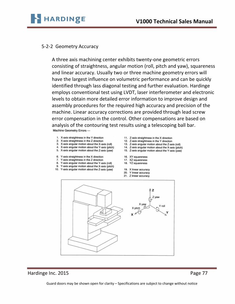
5‐2‐2 Geometry Accuracy
A three axis machining center exhibits twenty‐one geometric errors consisting of straightness, angular motion (roll, pitch and yaw), squareness and linear accuracy. Usually two or three machine geometry errors will have the largest influence on volumetric performance and can be quickly identified through lass diagonal testing and further evaluation. Hardinge employs conventional test using LVDT, laser interferometer and electronic levels to obtain more detailed error information to improve design and assembly procedures for the required high accuracy and precision of the machine. Linear accuracy corrections are provided through lead screw error compensation in the control. Other compensations are based on analysis of the contouring test results using a telescoping ball bar.

V1000 Technical Sales Manual
Hardinge Inc. 2015 Page 78
Guard doors may be shown open for clarity – Specifications are subject to change without notice
5‐2‐3 Contouring Performance Using Telescoping Ball Bar
The telescoping ball bar provides a quick and efficient way of measuring a machine tool’s contouring accuracy. Circular contours provide one of the best checks for contouring performance, in that as a machine is traversing with multiple axes along a circular trajectory, each axis goes through sinusoidal acceleration, velocity and position changes.

V1000 Technical Sales Manual
Hardinge Inc. 2015 Page 79
Guard doors may be shown open for clarity – Specifications are subject to change without notice
5‐2‐3 Contouring Performance Using Telescoping Ball Bar (continued)
In addition to out of roundness, contouring errors also show themselves as distinctive shapes in the telescoping Ballbar plots. Squareness errors show as ovals at 45° angles; linear accuracy as ovals at 90° and 180°; reversal errors as small deviations at 0°, 90°, 270° and360°; servo adjustment errors as smooth deviations just before 0°, 90°, 270° and360° positions; loose gibs as sawtooth patterns. Analysis of the shapes and errors are used to optimize the machine’s accuracy by appropriate changes in the compensation parameters in the device and the control, as well as fine tuning of mechanical components, if required.

V1000 Technical Sales Manual
Hardinge Inc. 2015 Page 80
Guard doors may be shown open for clarity – Specifications are subject to change without notice
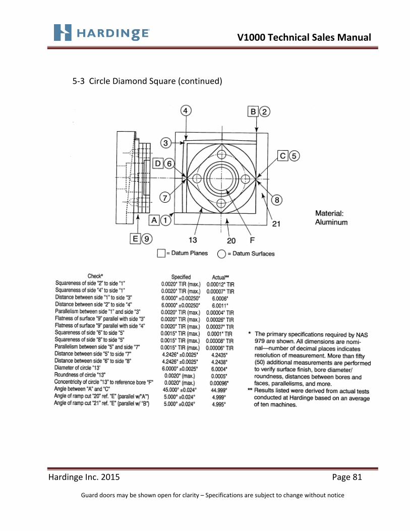
5‐3 Circle Diamond Square
The circle‐diamond‐square test is performed on every Conquest V1000 machine to insure that all specifications comply with ANSI\ASME standard B5.54, which permits the use of a test cut confirming to National Aerospace Standard NAS 979. This cutting performance test is intended to provide a comprehensive set of measurements to verify and demonstrate machining accuracy parameters, including straightness, flatness, parallelism, perpendicularity, squareness and circularity. The test involves independent axis motions along the machine axes, as well as simultaneous motions in the plane of the table along both diagonals, and circular interpolation for contouring. The size of the finished square is typically one‐third the table travels. The circle‐diamond‐square specimen may be modified to include drilling and tapping holes to test positioning accuracy and repeatability, as well as reduce the material management and setup requirements. The main purpose of the test is to verify and certify machine accuracy. Therefore, the test is performed in a controlled fashion, using finish cuts on soft materials to minimize the impact of tool deflection.
V1000 Technical Sales Manual
Hardinge Inc. 2015 Page 81
Guard doors may be shown open for clarity – Specifications are subject to change without notice
5‐3 Circle Diamond Square (continued)

V1000 Technical Sales Manual
Hardinge Inc. 2015 Page 82
Guard doors may be shown open for clarity – Specifications are subject to change without notice
Section 6 Mitsubishi M70V CNC Control System

V1000 Technical Sales Manual
Hardinge Inc. 2015 Page 83
Guard doors may be shown open for clarity – Specifications are subject to change without notice
6 Mitsubishi M70V Control
The control panel is custom‐designed to be user friendly especially in the placement of the buttons and identifying nomenclature. The control module conveniently swings for better user access. Large 10.4” color LCD display screen aids in viewing the various programming and function pages. The control is feature laden and programming is FANUC compatible.

V1000 Technical Sales Manual
Hardinge Inc. 2015 Page 84
Guard doors may be shown open for clarity – Specifications are subject to change without notice
6‐1 Standard Mitsubishi M70V Control Features
General Programmable Resolution—.0001”/.001mm Tool Offset Capability—.0001”/.001mm Inch/Metric Data Selection by G‐Code 1280 Meters Part Program Storage Part Program Storage USB or Compact Flash Data Input/Output ‐ USB or Compact Flash MDI (Manual Data Input) Operation
Programming Functions
Absolute/Incremental Programming Custom Macro Variables 700 Sets Maximum Work Piece Coordinates (54 Sets) Auto Coordinate System Setting Auto Acceleration/Deceleration Auto Corner Override Background Editing Canned Cycles (Drilling) Navi‐Mill® Conversational Programming Buffer Editing (Edit program while it’s running) Chamfer/Corner Rounding Coordinate System Setting (G50) Coordinate Rotation By G Code (G68/G69) Custom Macro Decimal Point Programming Input of Offset Value via Program (G10)

V1000 Technical Sales Manual
Hardinge Inc. 2015 Page 85
Guard doors may be shown open for clarity – Specifications are subject to change without notice
6‐1 Standard Mitsubishi M70V Control Features (continued)
Extended Part Program Edit (Copy/Paste) External Workpiece Number Search Scaling (G50/G51) Program Number Search Reference Point Return Registered Part Programs (1,000 Programs) Pocketing, Tapping, Deep Hole Peck Cycles Rigid Tapping Sequence Number Search Single Block Operation Stored Stroke Check Tool Life Management Tool Radius Compensation Tool Length Compensation Helical Interpolation Cylindrical Interpolation Spiral\Conical Interpolation Polar Coordinate Command Max Tool Compensation 400 Sets High Accuracy Control (G61.1, G08) High Speed Machining and Accuracy Control Mode I (G5.1 Q1/Q0) High Speed Machining and Accuracy Control Mode II (G5.1 P10000/P0) Simple SSS (Super Smooth Surface) Control Spline (G5.1Q2X0/Y0/Z0Q0) High Accuracy Spindle Interpolation (G61.2) Max Block Look Ahead 337 Work Piece Measurement (Surface/Hole/Width/Rotation) Manual Spindle Command

V1000 Technical Sales Manual
Hardinge Inc. 2015 Page 86
Guard doors may be shown open for clarity – Specifications are subject to change without notice
6‐1 Standard Mitsubishi M70V Control Features (continued) Operation Block Delete Dry Run Dwell Time Emergency Stop Feed Hold Feedrate Override (0 to 150%)
Jog Feed Machine Lock On Screen Spindle Load Monitoring Option Stop Rapid Traverse Override (Low‐25‐50‐100%) Tool Geometry and Tool Wear Offsets (80 pairs each) Flash Card Compatibility USB Compatibility RS‐232C Compatibility Ethernet Compatibility Manual Speed Control
Miscellaneous Actual Speed Display Alarm Display Clock Function
10.4 “ Color LCD Display with Full Keyboard French, German, Italian or Spanish Languages
Ladder Diagram Display Extensive “On Screen Help” Functions for Alarms Spindle Orient Run Time and Parts Counter Self Diagnosis Function Menu List Operation and G Code Guidance

V1000 Technical Sales Manual
Hardinge Inc. 2015 Page 87
Guard doors may be shown open for clarity – Specifications are subject to change without notice
6‐1 Standard Mitsubishi M70V Control Features (continued) Alarm and Parameter Guidance Program Restart 3D Solid Graphic and Program Check 2D Graphic Program Check and Trace Big Tool Function (4 Tools) NC Data Backup (Auto/Manual) Vertical Axis Drop Prevent When Power Down Operation Function Optional Block Skip Manual Interruption Automatic Operation Handle Interruption Manual Absolute Switch Tapping Retract Arbitrary Reverse Run Reference Position Retract Manual Tool Length Measurement Manual Pulse Generator (MPG Handwheel)

V1000 Technical Sales Manual
Hardinge Inc. 2015 Page 88
Guard doors may be shown open for clarity – Specifications are subject to change without notice
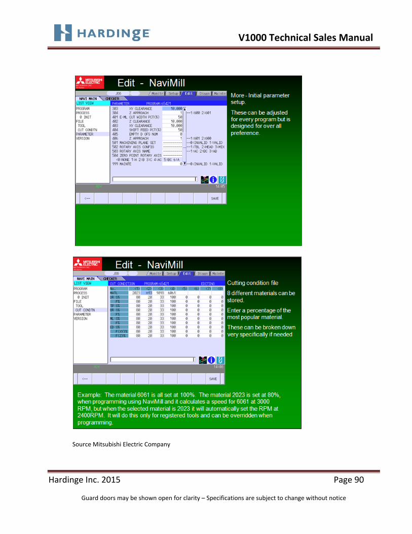
6‐2 Conversational Programming (Navi‐Mill) Feature
The Navi‐Mill feature allows less‐experienced programmers to easily create part programs from part drawings. Experienced programmers can also benefit from Navi‐Mill by using the desired features in their part programs. Manual programming knowledge is required to utilize the Navi‐Mill feature.
Source Mitsubishi Electric Company

V1000 Technical Sales Manual
Hardinge Inc. 2015 Page 89
Guard doors may be shown open for clarity – Specifications are subject to change without notice
Source Mitsubishi Electric Company
V1000 Technical Sales Manual
Hardinge Inc. 2015 Page 90
Guard doors may be shown open for clarity – Specifications are subject to change without notice
Source Mitsubishi Electric Company

V1000 Technical Sales Manual
Hardinge Inc. 2015 Page 91
Guard doors may be shown open for clarity – Specifications are subject to change without notice
Source Mitsubishi Electric Company

V1000 Technical Sales Manual
Hardinge Inc. 2015 Page 92
Guard doors may be shown open for clarity – Specifications are subject to change without notice
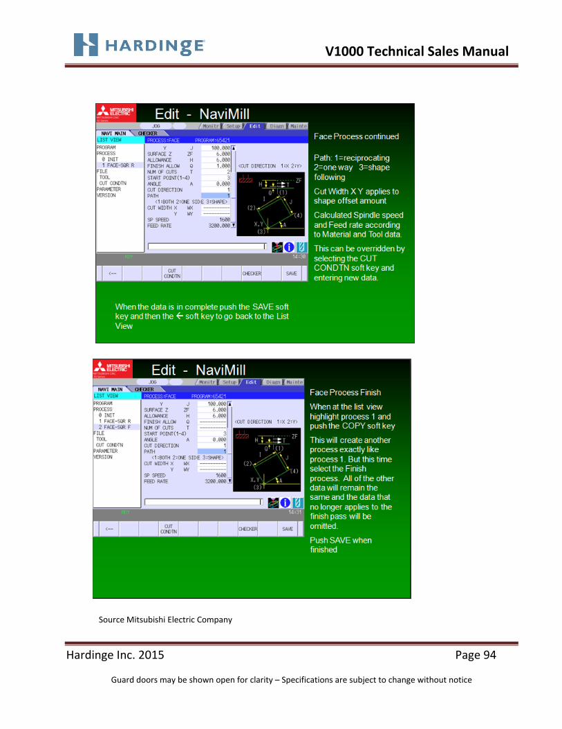
Source Mitsubishi Electric Company

V1000 Technical Sales Manual
Hardinge Inc. 2015 Page 93
Guard doors may be shown open for clarity – Specifications are subject to change without notice
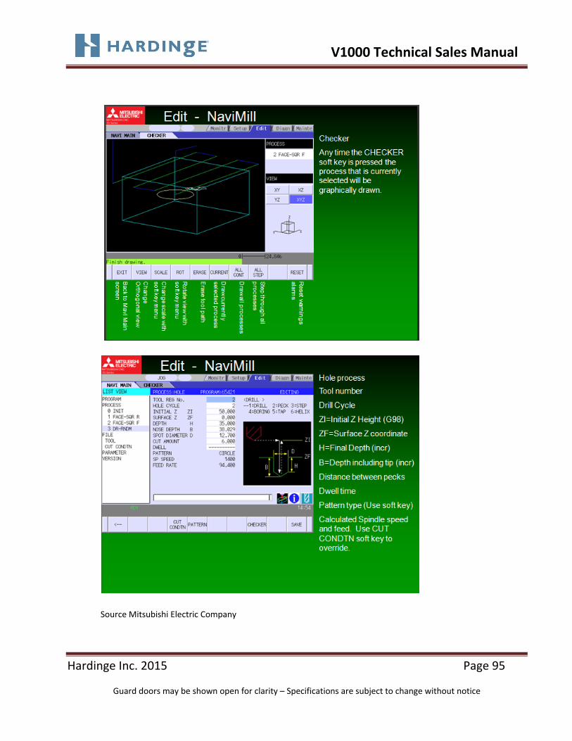
Source Mitsubishi Electric Company
V1000 Technical Sales Manual
Hardinge Inc. 2015 Page 94
Guard doors may be shown open for clarity – Specifications are subject to change without notice
Source Mitsubishi Electric Company
V1000 Technical Sales Manual
Hardinge Inc. 2015 Page 95
Guard doors may be shown open for clarity – Specifications are subject to change without notice
Source Mitsubishi Electric Company

V1000 Technical Sales Manual
Hardinge Inc. 2015 Page 96
Guard doors may be shown open for clarity – Specifications are subject to change without notice
Source Mitsubishi Electric Company

V1000 Technical Sales Manual
Hardinge Inc. 2015 Page 97
Guard doors may be shown open for clarity – Specifications are subject to change without notice
Source Mitsubishi Electric Company

V1000 Technical Sales Manual
Hardinge Inc. 2015 Page 98
Guard doors may be shown open for clarity – Specifications are subject to change without notice
Source Mitsubishi Electric Company

V1000 Technical Sales Manual
Hardinge Inc. 2015 Page 99
Guard doors may be shown open for clarity – Specifications are subject to change without notice
6‐3 Programming Feature Descriptions Rigid Tapping Rigid tapping capability eliminates the need for expensive tension and compression tap holders or collets and provides for faster tapping speeds and improved depth control. This is accomplished by synchronizing spindle rotation with axis motion, including acceleration and deceleration.
Chamfer or Corner Rounding:
With this feature a corner can be chamfered with a simple ,R or ,C
command.
Coordinate System Setting (G50):
The ability to set a work coordinate position through the program. Hardinge
does not teach this method of programming for axis pre‐setting, it is used
with constant surface speed.
Custom Macro B:
Allows the programmer the ability to use and manipulate variables with
custom macros for specialized machining cycles. Hardinge has programmed
and stored automatic cycles which the programmer may recall and execute
in his part program, reducing programming time.
Exact Stop:
Forces the machine to move with a specific tolerance of the exact position
programmed. This eliminates floating around a corner at fast axis feed
rates.

V1000 Technical Sales Manual
Hardinge Inc. 2015 Page 100
Guard doors may be shown open for clarity – Specifications are subject to change without notice
Extended Part Program Edit:
Gives you the ability to copy, move, and replace parts of a program similar
to cut, copy and paste functions.
Input of Offset Value via Program (G10 Command):
A G10 command can be used in the part program to change workshift, tool
geometry and tool wear offset values in either absolute or incremental.
Stored Stroke Check :
Allows setting up through parameters, a forbidden zone so as to not allow a
cutting tool into this defined area. For example this could be used to set up
a forbidden zone around a 3 jaw chuck.
Data Input and Output:
Uploading and downloading of data to the machine control can be done
thru the USB, PCMCIA (ATA Flash) Card slot, RS232C port or the Ethernet
port.
Actual Feed Display:
The LCD screen will display the actual feed rate of an axis in ipm or mmpm
(depending on machine setting). Feed rate may vary depending on where
the feedrate override switch is set.
Auto Coordinate System Setting:
The axis will return to the coordinate when a “Manual Rapid Reference”
function is executed.

V1000 Technical Sales Manual
Hardinge Inc. 2015 Page 101
Guard doors may be shown open for clarity – Specifications are subject to change without notice
Background Editing:
While a active part program is being executed, another part program may
be called up for editing by the operator without interrupting production.
Dry Run:
With the dry run switch on, all programmed feedrates (including rapid) are
set to 40 inches per minute. Machine axis motion may be stopped by
pressing feed hold or turning the feed rate override. switch to zero.
Edit Rapid Override (G00 button):
After a program edit has been made, the machine will go into a “slow
mode” rapid override to allow the operator a chance to stop operation if
start up of program was not incorrect position in the program or an edit
change was incorrect.
Graphic Part and Tool Path Display (MGI):
Allows the tool path to be simulated on the LCD screen to verify for
accuracy.
MDI (Manual Data Input) Operation:
MDI allows the operator to input program commands, for “one shot”
operations. Program is loaded in one block at time into the control using the
keyboard. This function can be used to start spindles, index the turret and
etc. Program commands once executed are dumped from the control
memory.

V1000 Technical Sales Manual
Hardinge Inc. 2015 Page 102
Guard doors may be shown open for clarity – Specifications are subject to change without notice
Machine Lock:
The machine movements, spindles and axis, can be “locked” while
executing the program. This feature permits the operator to check the
program for format errors.
Manual Pulse Generator (MPG):
The operator can control all axis motion at varying increments, using the
hand wheel on the operator’s panel.
Mechanical Run Meter:
Monitors the amount of time the main disconnect switch has been in the
“On” position.
On Screen Spindle and Axis Load Meters:
Allow monitoring of the axis and spindle load conditions during cutting
operations. A bar graph is displayed on the LCD screen.
Program Protect:
A key switch on the control used to protect programs that are in the
control’s memory from unintentional changes.
Rapid Traverse Override Switch:
A switch used to allow the operator to manually override a programmed
rapid move from Low ‐ 25% ‐ 50% ‐ 100%.
Rapid Reference Push Button:
Allows the operator to quickly reference an axis to its reference position.

V1000 Technical Sales Manual
Hardinge Inc. 2015 Page 103
Guard doors may be shown open for clarity – Specifications are subject to change without notice
Run Time Parts Counter:
The LCD screen will provide run time (total time the machine runs in
automatic operation), cycle time (run time of a single cycle in auto mode,
reset at cycle start) and parts counter (counts the number of parts
machined from the start of the job, this can be set to automatically stop the
machine after a predetermined number of parts have been produced).
Single Block:
With the single block push button on or the operational mode selector
switch set to single block, the control will only read and execute on block of
information each time the cycle start button is pressed..
Tool Offsets:
There are 80 pairs of tool offsets for each axis (depending on options),
included are both geometry and wear files. Geometry offsets are used to
compensate for different tool sizes and lengths. Wear offsets are used to
compensate for cutting tool wear, allowing the operator to maintain parts
size.
Tool Life Management:
The ability to control the time a tool is used, either by number of cycles or
amount of cutting time. Once the tool life has been expended a new tool
can be called automatically or the machine will generate an alarm and stop
production.
Coordinate System Rotation:
Allows the work coordinate system to be rotated at an angle for angular
rotation of the part features. .

V1000 Technical Sales Manual
Hardinge Inc. 2015 Page 104
Guard doors may be shown open for clarity – Specifications are subject to change without notice
Helical Interpolation:
Allows 3 axis simultaneous operation for helical milling and thread milling
operations. Standard on Y‐axis machines.
Work Coordinate System:
Allows user to access the work coordinate system locations G54 thru G59.
This is standard on all sub spindle machines.
V1000 Technical Sales Manual
Hardinge Inc. 2015 Page 105
Guard doors may be shown open for clarity – Specifications are subject to change without notice
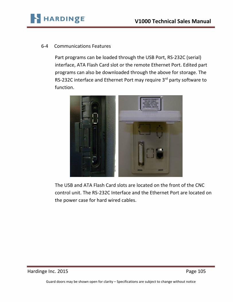
6‐4 Communications Features
Part programs can be loaded through the USB Port, RS‐232C (serial)
interface, ATA Flash Card slot or the remote Ethernet Port. Edited part
programs can also be downloaded through the above for storage. The
RS‐232C interface and Ethernet Port may require 3rd party software to
function.
The USB and ATA Flash Card slots are located on the front of the CNC
control unit. The RS‐232C Interface and the Ethernet Port are located on
the power case for hard wired cables.

V1000 Technical Sales Manual
Hardinge Inc. 2015 Page 106
Guard doors may be shown open for clarity – Specifications are subject to change without notice
6‐5 Machine and CNC Control Power Case

V1000 Technical Sales Manual
Hardinge Inc. 2015 Page 107
Guard doors may be shown open for clarity – Specifications are subject to change without notice
Section 7
OPTIONS

V1000 Technical Sales Manual
Hardinge Inc. 2015 Page 108
Guard doors may be shown open for clarity – Specifications are subject to change without notice
7 Options
7‐1 Thru Spindle Coolant (TSC) 280psi The Thru Spindle Coolant (TSC) feature allows coolant to be fed through the spindle (by means of a rotary union into the drawbar) and delivered to the workpiece to flush chips, as well as ot lubricate and cool tools. This option is mainly used for deep hole drilling, reaming and boring operations however can be utilized with any coolant fed type tooling. The machine comes “prepped” with the plumbing in place. This option consists of the rotary union and the coolant pump required facilitating the option. Tools and retention knobs with through the tool coolant capabilities are required.

V1000 Technical Sales Manual
Hardinge Inc. 2015 Page 109
Guard doors may be shown open for clarity – Specifications are subject to change without notice
7‐2 Linear Scales (X,Y and Z Axes) Factory Installed Only
Linear scales provide a closed‐loop feedback system the X, Y and Z axes for measuring the movement and compensating according to command. Although the Conquest V1000 is a very accurate machine without linear scales, the scales do improve cutting performance over a greater number of parts for such applications as contouring, die work and boring. The scales improve positioning accuracy by direct measurement, removing system affects such as ball screw stiffness and thermal migration. Heidenhain scales are utilized along with an air purge to minimize coolant contamination. Scale resolution is .000010”/.00025mm.
• The CONQUEST V1000 machine is designed, built and tested to comply with ISO 230‐2 geometric accuracy and alignment standards.
• Positioning Accuracy in all axes is 0.0004” (10μm) Full Stroke • Repeatability Accuracy in all axes is 0.0002” (5μm) Full Stroke • Positioning Accuracy with Scales in all axes is 0.0002” (5μm) Full Stroke • Repeatability Accuracy with Scales in all axes is 0.00016” (4μm) Full Stroke • All machines are fully Laser & Ballbar Tested

V1000 Technical Sales Manual
Hardinge Inc. 2015 Page 110
Guard doors may be shown open for clarity – Specifications are subject to change without notice
7‐3 Cutter Air Blast The Cutter Air Blast feature delivers a flow of air to the cutting zone for dry cutting applications as well as to clear chips from the cutting zone. It is programmable via M codes.
7‐4 Tool Probe
A Renishaw Tool Probe Model OTS with OMI‐2T interface is available for tool probing functions. The Renishaw Probe mounts directly to the table and offers the following features:
Setting Tool Diameter Offsets
Updating Tool Offsets
Tool Breakage Detection
Uses Renishaw Provided Macros

V1000 Technical Sales Manual
Hardinge Inc. 2015 Page 111
Guard doors may be shown open for clarity – Specifications are subject to change without notice
7‐5 Part Probe
The Renishaw Model OMP‐40‐2 Part Probe offers in‐process measurement for automatic update/compensation of coordinate values for workpiece’s including the following features:
Protected Positioning (probe stops in the event of a collision with anything other than the area specified for probing)
Single Measure Surface
Web Pocket Measurement
Boss\Bore Measurement
Internal\External Corner Find
4th Axis X and Y Measure
4th Axis Surface Measure
Uses Renishaw Supplied Macros
V1000 Technical Sales Manual
Hardinge Inc. 2015 Page 112
Guard doors may be shown open for clarity – Specifications are subject to change without notice
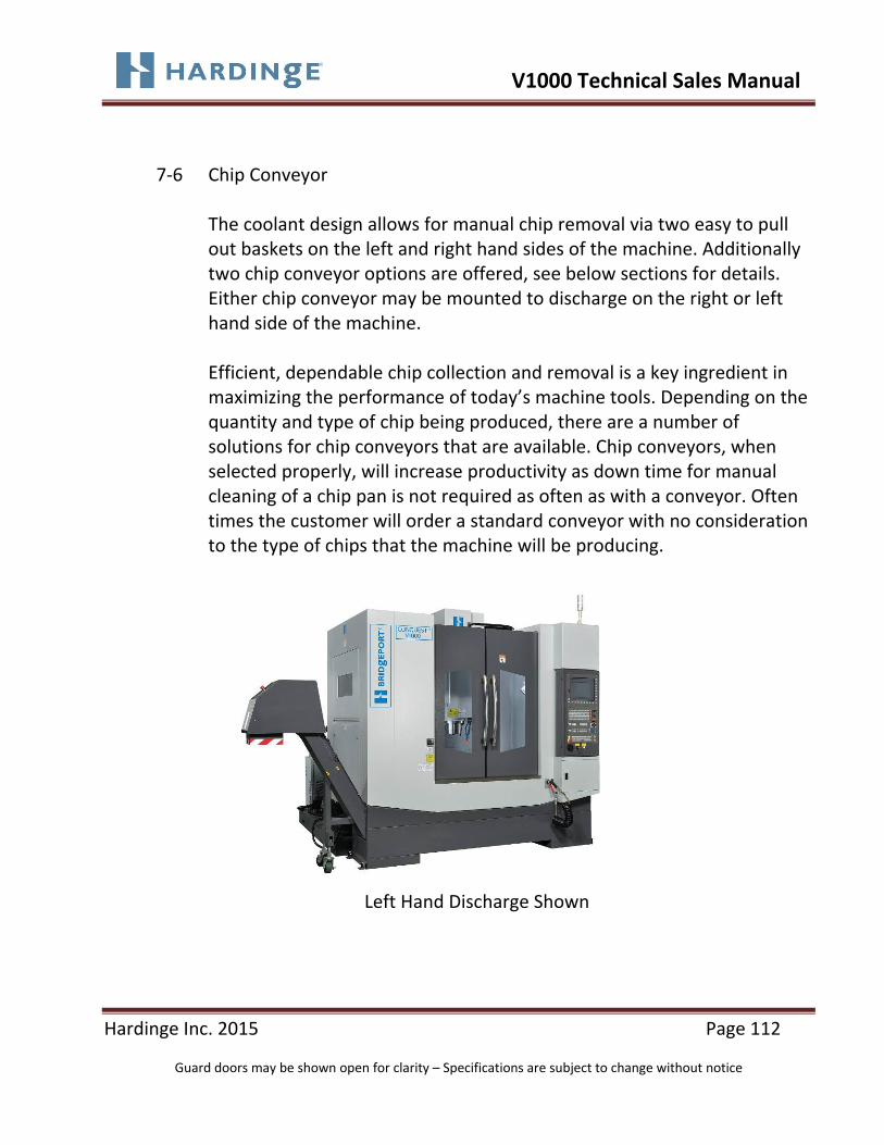
7‐6 Chip Conveyor
The coolant design allows for manual chip removal via two easy to pull out baskets on the left and right hand sides of the machine. Additionally two chip conveyor options are offered, see below sections for details. Either chip conveyor may be mounted to discharge on the right or left hand side of the machine. Efficient, dependable chip collection and removal is a key ingredient in maximizing the performance of today’s machine tools. Depending on the quantity and type of chip being produced, there are a number of solutions for chip conveyors that are available. Chip conveyors, when selected properly, will increase productivity as down time for manual cleaning of a chip pan is not required as often as with a conveyor. Often times the customer will order a standard conveyor with no consideration to the type of chips that the machine will be producing.
Left Hand Discharge Shown

V1000 Technical Sales Manual
Hardinge Inc. 2015 Page 113
Guard doors may be shown open for clarity – Specifications are subject to change without notice
7‐6.1 Hinge Type
Hinge Belt Style: This style carries the chips on the top of a hinged belt and is recommended for larger types of chips, such as steel, as well as long curly or stringy types of chips. The belt surface is often perforated with holes to facilitate coolant drainage back into the tank. When used in applications with very fine chipping material, often the fine chips will fall through the perforations leading to chip build on the bottom of the coolant tank, clogged filters or pumps, jammed conveyor and the need to more frequently clean the tank, filters, pumps and conveyor system
V1000 Technical Sales Manual
Hardinge Inc. 2015 Page 114
Guard doors may be shown open for clarity – Specifications are subject to change without notice
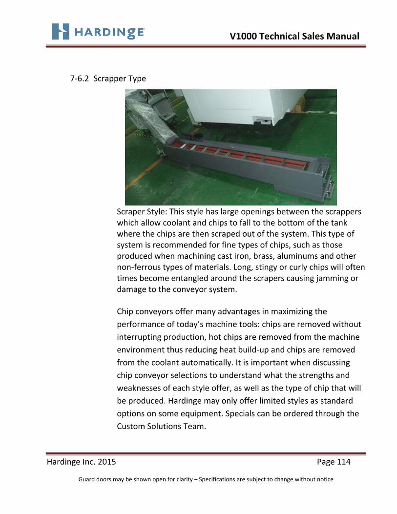
7‐6.2 Scrapper Type
Scraper Style: This style has large openings between the scrappers which allow coolant and chips to fall to the bottom of the tank where the chips are then scraped out of the system. This type of system is recommended for fine types of chips, such as those produced when machining cast iron, brass, aluminums and other non‐ferrous types of materials. Long, stingy or curly chips will often times become entangled around the scrapers causing jamming or damage to the conveyor system. Chip conveyors offer many advantages in maximizing the
performance of today’s machine tools: chips are removed without
interrupting production, hot chips are removed from the machine
environment thus reducing heat build‐up and chips are removed
from the coolant automatically. It is important when discussing
chip conveyor selections to understand what the strengths and
weaknesses of each style offer, as well as the type of chip that will
be produced. Hardinge may only offer limited styles as standard
options on some equipment. Specials can be ordered through the
Custom Solutions Team.

V1000 Technical Sales Manual
Hardinge Inc. 2015 Page 115
Guard doors may be shown open for clarity – Specifications are subject to change without notice
7‐7 Front Auto Door (Factory Install Only)
The Auto Door feature opens the main guard doors automatically via programmable M codes. This feature greatly reduces operator fatigue during repetitive machining operations, increasing operator productivity and allowing for unattended operation when used with automation. A light Curtain is included for operator safety.
7‐8 Tool Magazine Auto Door
The Tool Magazine Auto Door is a feature which automatically opens and closes during and after a tool change to minimize chip contamination into the tool changer area.

V1000 Technical Sales Manual
Hardinge Inc. 2015 Page 116
Guard doors may be shown open for clarity – Specifications are subject to change without notice
7‐9 Automatic Central Grease Lubrication System
The Automatic Central Grease Lubrication system eliminates the need for the operator to manually grease the machine when required. This feature allows for longer unattended operation and minimizes machine damage due to lack of lubrication. A low grease alarm will be activated when the unit requires refilling.
Automatic Central Grease Lubrication System

V1000 Technical Sales Manual
Hardinge Inc. 2015 Page 117
Guard doors may be shown open for clarity – Specifications are subject to change without notice
7‐10 Spindle Chiller
Machine tool spindles are a prime source of heat in any machine and precautions should be taken in adverse or heavy duty cycles at high rpm’s to minimize heat retention to insure long spindle life and minimize thermal distortion of the machine that could be a source of machine inaccuracy. As heat from the directly coupled motor to the spindle shaft travels down the shaft, thermal growth can alter the spindle dimensions and affect machine precision. Use of a spindle chiller is an excellent option for removing excess heat in the spindle, extending spindle life and decreasing thermal migrations in the machine.
Spindle Chiller

V1000 Technical Sales Manual
Hardinge Inc. 2015 Page 118
Guard doors may be shown open for clarity – Specifications are subject to change without notice
Section 8
FLOOR PLAN AND SPECIFICATIONS

V1000 Technical Sales Manual
Hardinge Inc. 2015 Page 119
Guard doors may be shown open for clarity – Specifications are subject to change without notice
8 Floor Plan and Specifications 8‐1 Floor Plan
Conquest V1000 machines require a substantial foundation. Do not locate the machine near equipment that causes vibration. Poor surface finishes or damage to the control may result from vibration transmitted to the machine. Avoid placing the machine over floor expansion joints.
Recommended:
6 inch (152 mm) thick concrete floor as large as the machine footprint. The machine footprint is the overall dimensions, length and width, of the machine. Approximate Weights Machine weight: 15,400 lb (7,000 Kg)

V1000 Technical Sales Manual
Hardinge Inc. 2015 Page 120
Guard doors may be shown open for clarity – Specifications are subject to change without notice
8‐1 Floor Plan (continued)
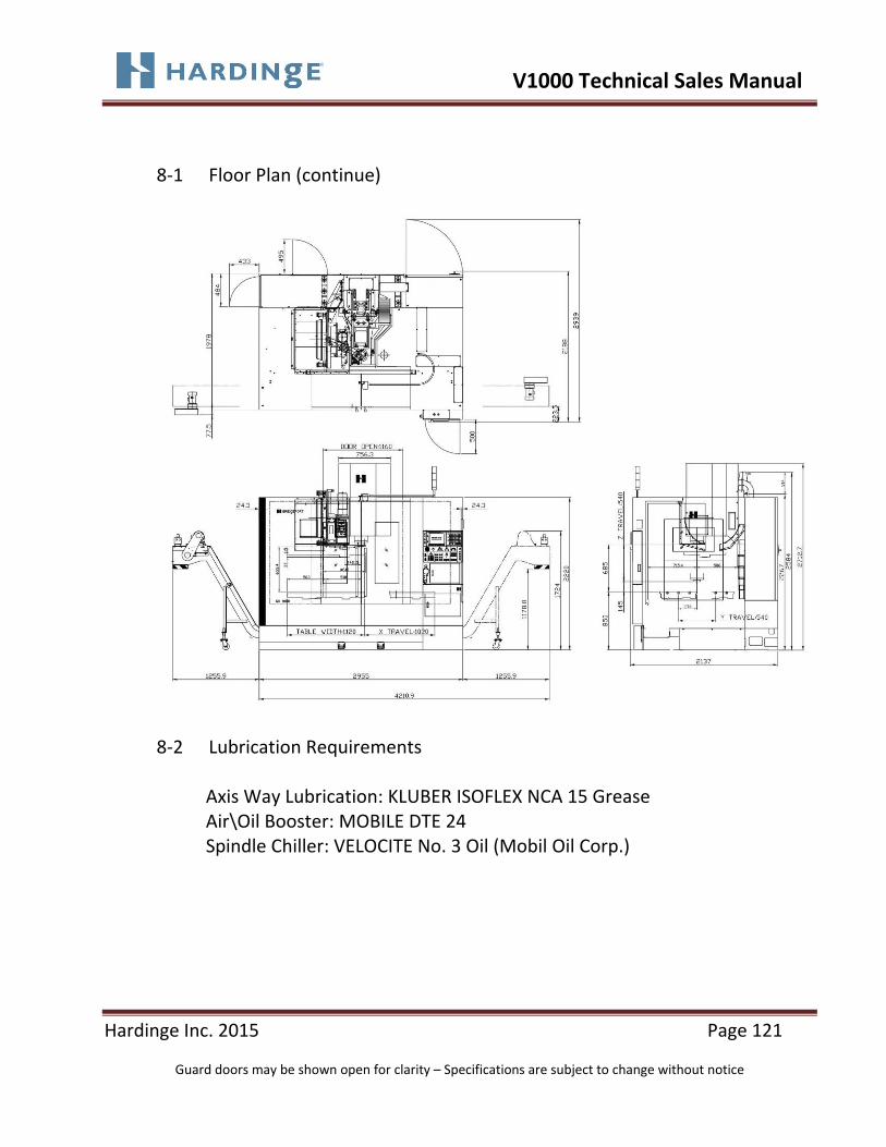
V1000 Technical Sales Manual
Hardinge Inc. 2015 Page 121
Guard doors may be shown open for clarity – Specifications are subject to change without notice
8‐1 Floor Plan (continue)
8‐2 Lubrication Requirements
Axis Way Lubrication: KLUBER ISOFLEX NCA 15 Grease Air\Oil Booster: MOBILE DTE 24 Spindle Chiller: VELOCITE No. 3 Oil (Mobil Oil Corp.)

V1000 Technical Sales Manual
Hardinge Inc. 2015 Page 122
Guard doors may be shown open for clarity – Specifications are subject to change without notice
8‐3 Power Requirements
‐Caution‐ Customer must provide transformer protection per local code. Power entrance to the case must comply with local electrical codes. Due to the variation of local electrical codes, Hardinge recommends that the local utility supply company be consulted to determine exact service and wiring requirements. Machine Electrical Requirements
Input Voltage: 220 (3 Phase 60Hz)
FLA (Full Load Amps): 79FLA (36Kva)
8‐4 Air Requirements
An inline air regulator and lubricator are included as standard equipment. Air Pressure Required 90 psi (6.2 bar) Hardinge recommends adding a heavy‐duty air dryer to the incoming air line if excessive moisture is present.

V1000 Technical Sales Manual
Hardinge Inc. 2015 Page 123
Guard doors may be shown open for clarity – Specifications are subject to change without notice
8‐5 Power Case

V1000 Technical Sales Manual
Hardinge Inc. 2015 Page 124
Guard doors may be shown open for clarity – Specifications are subject to change without notice
Section 9
MACHINE SPECIFICATIONS
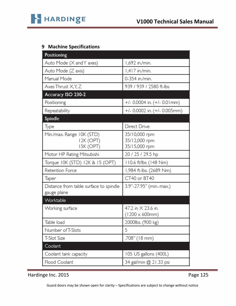
V1000 Technical Sales Manual
Hardinge Inc. 2015 Page 125
Guard doors may be shown open for clarity – Specifications are subject to change without notice
9 Machine Specifications

V1000 Technical Sales Manual
Hardinge Inc. 2015 Page 126
Guard doors may be shown open for clarity – Specifications are subject to change without notice
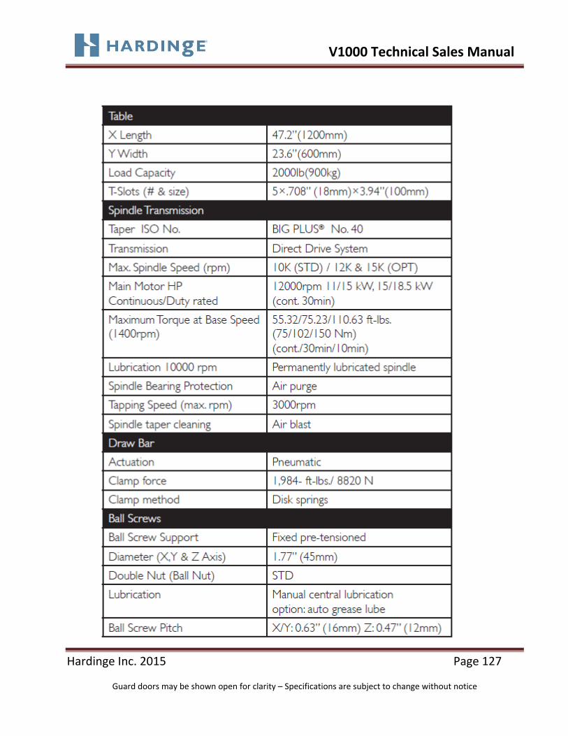
V1000 Technical Sales Manual
Hardinge Inc. 2015 Page 127
Guard doors may be shown open for clarity – Specifications are subject to change without notice

V1000 Technical Sales Manual
Hardinge Inc. 2015 Page 128
Guard doors may be shown open for clarity – Specifications are subject to change without notice

V1000 Technical Sales Manual
Hardinge Inc. 2015 Page 129
Guard doors may be shown open for clarity – Specifications are subject to change without notice
Section 10
ADDITIONAL PRODUCT SUPPORT INFORMATION

V1000 Technical Sales Manual
Hardinge Inc. 2015 Page 130
Guard doors may be shown open for clarity – Specifications are subject to change without notice
10. Additional Product Support Information
Hardinge offers a tremendous amount of backup and support documentation that is readily available in a number of places including the Distributor SharePoint Portal, Applications, Service, Marketing and Sales teams. Listed below are some of the more pertinent information in reference to the Conquest V1000 machines.
10‐1 Helpful Hints
Helpful Hints are a series of communicators developed by the Hardinge Applications Engineering Team on a variety of subjects which are meant to be an aid to the sales force and customer. HH002 Chip Conveyor Styles and Applications HH004 Mist Collector Systems – Information To Consider HH005 Coolant Chillers HH006 High Pressure Coolant Systems HH007 Accuracy Definitions The above documents can be downloaded from the Distributor SharePoint Portal in the Applications Area
10‐2 Standard Machine Documentation Package
The standard documentation package supplied with all V series machines is developed by the Technical Writing Team at Hardinge. In addition to a complete Mitsubishi documentation package, the following documentation supplied and is also available on the Hardinge Service website www.hardingeservice.com :
1902615 (Mitsubishi)/1902505 (Fanuc)/1902507 (Simens): Operation Manual
1902493: Maintenance Manual

V1000 Technical Sales Manual
Hardinge Inc. 2015 Page 131
Guard doors may be shown open for clarity – Specifications are subject to change without notice
1902494: Pre Delivery & Installation Guide
GX 000950V1000: Parts List
Machine Footprint/1902494: Floor Plan Layout
Chapter 2.5/1902493: Pneumatic Schematic
Chapter 4.10/1902493: Hydraulic Schematic
Chapter 3.12/1902493: Coolant System Diagram
The above documents can be downloaded from the www.hardingeservice.com website.
10‐3 Sales and Marketing Documentation
The sales and marketing teams create all machine brochures, trade publication advertisements as well as numerous PowerPoint presentations that are available. Please contact the Sales, Marketing or Applications Teams for information on what is available or if you require something specific.
Revisions Log: 12/2/2015 First Revision Draft 2/9/2016 Final Revision from HT Review and Updated