
Submission - Department of Agriculture, Fisheries and Forestry
IBSM Manual
IBSMInstallation and Programming Manual
This Manual describes the IBSM InterBus-S Master, its uses and set up. It also describes the use of the IBSMconfiguration software.
Effective: 12 June, 2000
Niobrara Research & Development CorporationP.O. Box 3418 Joplin, MO 64803 USA
Telephone: (800) 235-6723 or (417) 624-8918Facsimile: (417) 624-8920Internet: http://www.niobrara.com

SY/MAX and Square D are registered trademarks of Square D Company.
Subject to change without notice.
© Niobrara Research & Development Corporation 1995-2000. All Rights Reserved.

3
Contents
1 Introduction .........................................................................................................................7
Specifications .................................................................................................................8Module Specifications .............................................................................................8
2 Installation ...........................................................................................................................11
Module Installation .......................................................................................................11IBSMSW Software Installation ....................................................................................12Serial Connection to the IBSM ....................................................................................13IBS installation .............................................................................................................15
3 Operation .............................................................................................................................17
InterBus-S Overview ....................................................................................................17Memory Configuration .................................................................................................18
PLC Rack Addressable Area .................................................................................19InterBus-S Inputs...................................................................................................20InterBus-S Outputs ................................................................................................20Intended IBS Layout .............................................................................................21Actual IBS Layout .................................................................................................22Module Error Counters..........................................................................................23IBSM Error Counter ..............................................................................................23IBSM Option Register ...........................................................................................24CRC Error Limit ....................................................................................................25COMM Parameters ...............................................................................................25IBSM Status Register ............................................................................................26IBS Health Register ...............................................................................................26Miscellaneous IBSM Errors ..................................................................................26IBS Scan Time ......................................................................................................26IBS Ring Word Size ..............................................................................................26Failed Terminal Number .......................................................................................27Layout Checksum..................................................................................................27Map Checksum......................................................................................................27Module Protection Password .................................................................................27Most Recent CRC Error Number ..........................................................................27Most Recent Module Error Number......................................................................27"Sticky" Module Status .........................................................................................27Aditional Statistical Registers ...............................................................................27MAP ......................................................................................................................28

4
Communication Port Number ...............................................................................29NR&D ASCII ID ...................................................................................................29
4 Configuration Software IBSMSW.....................................................................31
Data Entry Keys ...........................................................................................................31Main Menu ...................................................................................................................32oNline ...........................................................................................................................32
Edit Configuration .................................................................................................32Print Configuration ................................................................................................37
oFfline ..........................................................................................................................37Read from disk to memory ....................................................................................37Write from memory to disk ...................................................................................38Edit configuration in memory ...............................................................................38Send memory to master .........................................................................................38Fetch memory from master ...................................................................................38Print configuration in memory ..............................................................................38Delete configuration file ........................................................................................39Optimize map ........................................................................................................39Quit offline functions ............................................................................................39
Utility ............................................................................................................................39View registers .......................................................................................................40Download New Firmware to IBSM ......................................................................41BBS Terminal Emulator ........................................................................................43
SETUP ..........................................................................................................................44SY/MAX SETUP ..................................................................................................44Personal Computer COM: port .............................................................................44SY/LINK Connection ............................................................................................46Terminal Emulator SETUP ...................................................................................47
Command Line Parameters ..........................................................................................48
5 Connector Pinouts.........................................................................................................49
COMM RS-422 port on IBSM (DE9S with slide lock posts) ...............................49InterBus-S port on IBSM (DE9S with 4-40 jack sockets) ....................................50
6 Recommended Cabling..............................................................................................51
SY/MAX Cabling required to configure an IBSM ......................................................51IBSM to personal computer cabling......................................................................51
Cabling required to connect a IBSM port to an external device ..................................52IBSM RS-422 to SY/MAX RS-422 port ...............................................................52
InterBus-S Remote Network Cabling ...........................................................................52
Appendix A IBSM Display Messages ...................................................... 53
Appendix B NR&D Internet ............................................................................. 57

5
Figures
Figure 1-1 IBSM Front Panel .........................................................................................................9
Figure 2-1 IBSM initialization .....................................................................................................13
Figure 2-2 IBSMSW Main Menu .................................................................................................13
Figure 2-3 Sy/Max Setup Window ...............................................................................................14
Figure 2-4 IBSMSW oNline Edit .................................................................................................15
Figure 3-1 IBS example ................................................................................................................18
Figure 4-1 Main Menu Screen ......................................................................................................32
Figure 4-2 oNline Menu ..............................................................................................................33
Figure 4-3 oNline Edit ..................................................................................................................33
Figure 4-4 Intended IBS System Layout Editor ...........................................................................36
Figure 4-5 IBSM Mapper Editor ..................................................................................................36
Figure 4-6 oFfline Menu ..............................................................................................................37
Figure 4-7 Utility Menu................................................................................................................39
Figure 4-8 View Registers ............................................................................................................40
Figure 4-9 IBSM Firmware Load Switch .....................................................................................41
Figure 4-10 IBSM Firmware Download ......................................................................................42
Figure 4-11 Download Firmware .................................................................................................43
Figure 4-12 Terminal Emulator ....................................................................................................44
Figure 4-13 Setup Menu .............................................................................................................44
Figure 4-14 SY/MAX Setup Screen .............................................................................................45
Figure 4-15 SY/LINK Setup Screen .............................................................................................46
Figure 4-16 Terminal Emulator Setup Screen ..............................................................................47
Figure 5-1 SY/MAX RS-422 Connector Pinout .........................................................................49
Figure 5-2 InterBus-S Connector Pinout ......................................................................................50
Figure 6-1 InterBus-S Remote Cable ...........................................................................................52
Tables
Table 1-1 IBSM Register Grouping ...............................................................................................7
Table 2-1 IBSM Factory Default Settings ....................................................................................12
Table 2-2 IBSM Software List .....................................................................................................12
Table 3-1 IBSM Register List ......................................................................................................19
Table 3-2 PLC Rack Area ............................................................................................................19
Table 3-3 IBS Inputs ....................................................................................................................20
Table 3-4 IBS Outputs ..................................................................................................................21
Table 3-5 Intended IBS Layout ....................................................................................................22
Table 3-6 Actual IBS Layout .......................................................................................................23
Table 3-7 IBS Module Errors .......................................................................................................24
Table 3-8 IBSM Configuration ....................................................................................................25
Table 3-9 COMM Port Baud Rates ..............................................................................................25
Table 3-10 Additional Statistical Counters ..................................................................................28
Table 3-11 Mapper .......................................................................................................................29


IBSM Manual 1 Introduction 7
1
Introduction
The Niobrara IBSM (InterBus-S Master) is a SY/MAX® compatible module that per-forms the function of Host Controller on an InterBus-S network. The IBSM interfaceswith the SY/MAX PLC through the Square D SY/MAX register rack to provide ac-cess to the InterBus-S devices through the backplane. The IBSM PLUS provides thesame features of the IBSM with a guaranteed 16 bit-wide SY/MAX interface to thePLC.
Communication with the InterBus-S devices is through an isolated RS-485 InterBus-SRemote Bus connector on the front panel of the module.
All data is stored in the IBSM in standard 16 bit SY/MAX compatible registers. TheIBSM has 8192 registers which are divided into ranges for the PLC Rack Interface,InterBus-S Inputs, InterBus-S Outputs, InterBus-S Configuration, InterBus-S Statis-tics, IBSM Control and Status, and the IBSM Mapper. Table 1-1 displays this infor-mation.
Table 1-1 IBSM Register Grouping
RegisterRange
Function
1..512 PLC Rack Addressable Area
513..768 InterBus-S INPUTS
769..1024 InterBus-S OUTPUTS
1025..1281 Intended InterBus-S Layout
1282..1538 Actual InterBus-S Layout
1539..1794 InterBus-S Module Errors
1795..1803 IBSM Configuration
1804..2048 Not Used, READ as 0
2049..4548 MAP
4549..8175 Not Used, READ as 0
8176..8192 IBSM SY/MAX ID

8 Introduction 1 IBSM Manual
The Mapper is the key to the IBSM. The IBSM runs the InterBus-S network and setsthe InterBus-S Outputs based on values in its InterBus-S Output register area. InterBus-S Inputs are consequently placed in the module’s InterBus-S Input registers. The Mapper provides the mechanism for transferring these InterBus-S I/O values toand from the PLC rack. With certain restrictions, the Mapper is capable of copyingregister data from any location in the IBSM to any other location in the IBSM. Thisallows the mapping of PLC Outputs to InterBus-S Outputs, InterBus-S Inputs to PLCInputs, InterBus-S Inputs to other InterBus-S Outputs, IBSM control and statisticsregisters to and from the PLC rack, etc. The Mapper provides complex manipulationsincluding bit masking and bit rotations.
The configuration of the module is accomplished by setting parameters in the registersin the IBSM. This is most easily accomplished with the use of the IBSMSW.EXEprogram. This MS-DOS program provides a convenient interface for configuring andtroubleshooting the IBSM. This software is provided free of charge with the IBSM.
Specifications
Module Specifications
Mounting RequirementsOne register slot of a Square D Class 8030 Type CRK, DRK, GRK, HRK, orRRK I/O or the NR&D NRK2 rack assembly.
Current Draw on SY/MAX power supply 1100 mA
Operating Temperature0 to 60 degrees C operating. -40 to 80 degrees C storage.
Humidity Rating up to 90% noncondensing
Pressure Altitude-200 to +10,000 feet MSL
InterBus-S Communication Port9 pin D-connector, optically isolated RS-485 compatible. Fixed 500K baudInterBus-S protocol.
SY/MAX Communication Port9 pin D-connector, RS-422/485 compatible. Selectable baud rate, parity, errorcheck.
Indicator lights3 LEDs: Green Power, Yellow SY/MAX port RX, and TX.1 Four Character red LED Message Display.
Physical DimensionsSingle width module.Wt: 2.5 lb.W: 1.5 in.H: 12.8 in.D: 6.6 in.

IBSM Manual 1 Introduction 9
Figure 1-1 IBSM Front Panel
T E S T
TX RX
IBSMInterBus-SMaster
Power
Mode Indicators
Power (Green) - lights when module is powered.
Status (Red LED array) - Alphanumeric messagedisplay for module status information.
COMM Port
Female SY/MAX compatible RS-422communication port. This port is also used forfield downloading of new firmware into themodule.
Communication Indicators (LEDs)
TX (Yellow) - Lights when data is beingtransmitted from COMM port.
RX (Yellow) - Lights when data is beingreceived at COMM port.
RemoteBus
COMM
Remote Bus Port
InterBus-S standard 9-pin D-subminiatureconnection to remote bus.

IBSM Manual 2 Installation 11
2
Installation
Module Installation1 Remove power from the rack.
2 Mount the IBSM in an available slot in the register rack. Secure the screw at thebottom of the module.
3 Apply power to the rack. The green power light should illuminate and remain lit. The four character display should quickly flash the following messages: TEST,RAM1, RAM2, ROM1, ROM2, PASS, and then may display any of several mes-sages including: OPEN, SLER, RUN, HALT, DSBL, CFIG depending upon theexact configuration. If the message area displays LOAD, remove power, removethe module from the rack, locate the LOAD/NORMAL switch on the back of themodule, move the switch to the NORMAL position, reinstall the IBSM, and re-store power. (See Appendix A on page 53 for a complete listing of messages.)The lights above the 9 pin RS-422 COMM port on the illuminate only when datais passing through the port.
NOTE: If the slot that the IBSM occupies has been rack addressed by the PLCand an error message such as OPEN or CFIG is displayed on the IBSM, the PLCwill likely display an I/O Error and go into Halt. This is an example of the BUSerror feature of the IBSM. When a PLC BUS error occurs, Register 8175 in thePLC will display the decimal number 19000 + First register rack addressed to themodule. For example, the IBSM is in a slot rack addressed from 640 to 675.
WarningDo NOT install or remove the IBSM with power applied to theRack. Turn OFF power at the power supply. Damage to theequipment may occur if the power is on during installation.

12 Installation 2 IBSM Manual
When a bus error occurs, the decimal value 19640 will appear in PLC register8175. The IBSM may be configured such that this feature is disabled.
4 The IBSM will default to the settings held in non-volatile RAM. Factory defaultsettings are shown in Table 2-1.
Table 2-1 IBSM Factory Default Settings
IBSMSW Software InstallationThis MS-DOS compatible program runs on an IBM compatible personal computer. The software is distributed on a 3.5" 720K floppy and is compressed using an industrystandard .ZIP format. For automatic installation perform the following steps.
1 Insert the floppy into a drive and run the INSTALL program from that drive.
2 Enter the floppy drive name that contains the distribution disk.
3 Select IBSMSW from the list of softwares to install.
4 Enter a directory name to install the IBSMSW software. It is recommended that adirectory IBSM be used for the installation on your hard drive.
5 Once INSTALL is finished copying and expanding the files, exit by pressing theESC key until the DOS prompt is reached.
6 Change to the IBSM directory and perform a directory with the following com-mands:
C:CD \IBSM DIR
Table 2-2 lists the files that should appear in the directory. These files are describedin Chapter 4 on page 31.
Table 2-2 IBSM Software List
Parameter RS-422 COMMPort
Mode SY/MAX
Baud Rate 9600
Parity EVEN
Data Bits 8
Stop Bits 1
Checksum BCC
File Name Description
IBSMSW.EXE IBSM Configuration Software.
IBSM.ICO Icon for IBSMSW for Windows.
IBSM.FWL Downloadable firmware for the IBSM.

IBSM Manual 2 Installation 13
Serial Connection to the IBSMA physical connection must be made from the personal computer to the IBSM in orderfor IBSMSW to be able to fully function. This link may be a serial connection from aCOM port on the personal computer to the RS-422 port on the IBSM. Usually an RS-232 to RS-422 converter is required for this connection and the Niobrara SC902 (orSC406) smart cable is recommended. If the personal computer has a SY/LINK card,the RS-422 port on the SY/LINK card may be used to directly connect to the IBSM. Refer to page 46 for additional information on the SY/LINK setup.
Connect your personal computer to the IBSM. It is assumed here that this connectionwill be made from COM1: of the personal computer using an SC902 Smart Cable.
Start IBSMSW.EXE to communicate with the IBSM in SY/MAX mode.C:\IBSM> IBSMSW
The screen should appear as in Figure 2-2.
Figure 2-2 IBSMSW Main Menu
IBSM
POWER
IBSM
SC902 Cable
Figure 2-1 IBSM initialization
14 Installation 2 IBSM Manual
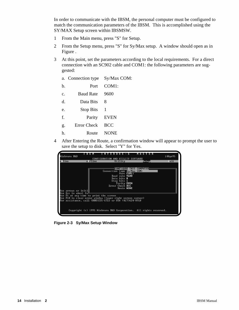
In order to communicate with the IBSM, the personal computer must be configured tomatch the communication parameters of the IBSM. This is accomplished using theSY/MAX Setup screen within IBSMSW.
1 From the Main menu, press "S" for Setup.
2 From the Setup menu, press "S" for Sy/Max setup. A window should open as inFigure .
3 At this point, set the parameters according to the local requirements. For a directconnection with an SC902 cable and COM1: the following parameters are sug-gested:
a. Connection type Sy/Max COM:
b. Port COM1:
c. Baud Rate 9600
d. Data Bits 8
e. Stop Bits 1
f. Parity EVEN
g. Error Check BCC
h. Route NONE
4 After Entering the Route, a confirmation window will appear to prompt the user tosave the setup to disk. Select "Y" for Yes.
Figure 2-3 Sy/Max Setup Window

IBSM Manual 2 Installation 15
Figure 2-4 IBSMSW oNline Edit
The personal computer is now ready to communicate with the IBSM. Press "N" foroNline followed by "E" for Edit and the TX and RX lights on the IBSM should startflashing. The screen on the personal computer should look something like Figure 2-4. The arrow keys are used to move the cursor around. Parameters may be changed bytoggling values with the space bar, - and + keys, or by direct entry of numeric fields. Use caution while changing fields that relate to the RS-422 Port; communication maybe interrupted if values such as baud rate, parity, or checksum are changed while on-line.
IBS installationThe IBSM connects to the InterBus-S network using its Remote Bus port. The IBSMuses the 2 Twisted-Pair Remote Bus Wiring scheme and the pinout of its 9 pin port iscompatible with Pheonix Contact products.. Connection to the first Remote Bus de-vice with a proper remote bus cable such as the Niobrara IR9D cable shown on page52. For a complete IBS overview see the Phoenix Contact document: InterBus-S In-struction Manual IBS SYS INST UM E Order No.: 27 54 804. This document maybe ordered from Pheonix Contact.
Connect an IBS network to the IBSM. The front display should change from OPENor SLER to CFIG. The CFIG message indicates that actual layout of the network doesnot match the intended layout. Since there is probably no intended layout stored in theIBSM, this means that the IBSM is at least communicating with the first remote busmodule.
At this point, go oNline and Edit the Intended Layout. The F2 key allows an easy wayto copy the actual layout to the intended layout. After copying the actual layout to theintended layout, leave this screen by pressing ESC and after the configuration is modi-fied, the CFIG message should change to HALT. If the PLC is then placed in RUNmode, the I/O error should be removed from the PLC and the IBSM will display RUN.The IBS is now operating and it is ready for use.

IBSM Manual 3 Operation 17
3
Operation
InterBus-S OverviewThe InterBus-S sensor/actuator network operates in a manner that is effectively a largeshift register. The IBSM keeps a table of registers that corresponds to all of the outputbits on the InterBus-S network. The IBSM also keeps a table that corresponds to all ofthe input bits on the IBS network. During a normal scan of the IBS network, theIBSM clocks output data to the network modules while the modules clock their inputdata to the IBSM. Each device on the IBS network checks the integrity of the datawith CRC calculations between nodes. The data must pass all checks around the loopbefore it is allowed to be latched in the outputs or placed in the IBSM’s input table.
This structure requires the IBSM and all of the modules on the IBS network to knowthe size of the network. This is accomplished by the IBSM issuing an ID cycle. TheID cycle information allows the IBSM to know the exact I/O module type and positionon the bus. The IBSM keeps a table of the current bus layout and compares the cur-rent bus to a table that contains the intended bus layout. If the tables do not match, theIBSM will halt the IBS network and, depending on its configuration, may cause a PLCbus error to halt the PLC.
The IBS serial protocol is implemented in two formats: remote bus and local bus. Both of these bus types operate in the same manner for shifting the data but differ intransmission distance.
The remote bus operates at differential RS-485 levels for long distance communica-tion of up to 1300 feet. Up to 32 remote bus devices may be connected to a singlemaster. Only serial communication is passed through the remote bus cable. Each re-mote bus device is independently powered as no power passes through the remote bus. The IBSM has a remote bus port and acts as the start of the remote bus. Remote busdevices are available that act as local bus terminals with and without I/O.
The local bus is intended for localized areas of I/O. The local bus is limited to 8 mod-ules with a maximum cable length of 32 feet. The communication ports of each local

18 Operation 3 IBSM Manual
bus device are powered by the remote bus terminal. The communication levels areTTL on the local bus.
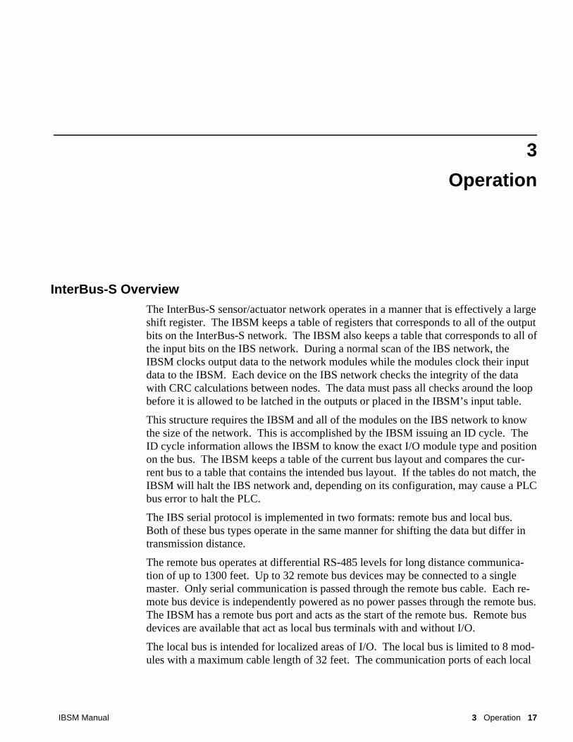
Figure 3-1 below shows a typical IBS network with 3 local bus groups. Group 1 con-sists of (1) a bus terminal without I/O, (2) a 16 bit digital input module and (3) a 16 bitdigital output module. Group 2 has (4) a bus terminal with 16 bits of input and 16 bitsof output, (5) a 16 bit digital input module, (6) a four channel analog input module,and (7) a four channel analog output module. Group 3 contains (8) a remote terminalwithout I/O, (9) (10) two 16 bit digital outputs, (11) one 16 bit digital input, and (12)another 16 bit digital output.
In the following configuration examples Figure 3-1 will be used for the sample data.
Figure 3-1 IBS example
Memory ConfigurationThe operation of the IBSM is determined by the configuration in its memory. TheIBSM’s internal user-accessible memory is represented as SY/MAX processor equiva-lent registers. All configuration parameters are stored and displayed in these registers. A list of available registers is shown in Table 3-1.
Inputs and Outputs
IBSM
POWER
IBSM
Digital Digital
Digital 4 Ch.
DigitalDigital Digital Digital
Remote Bus 1
Remote Bus 2
RemoteBus 3
Local Bus Group 1
Local Bus Group 2
Local Bus Group 3
(1) (2) (3)
(4) (5) (6) (7)
(8)(9) (10) (11) (12)
Input Output
BusTerminal
BusTerminal
BusTerminalwith Digital
AnalogInput
4 Ch.AnalogOutput
Input
Output Output Input Output

IBSM Manual 3 Operation 19
Table 3-1 IBSM Register List
PLC Rack Addressable Area
IBSM registers 1..512 are rack addressable by the SY/MAX PLC. The ability of thePLC to write these registers is controlled by the Mapper in the IBSM. By defaultthese registers are PLC outputs and the PLC can write values to these registers. PLCoutputs may be identified by their status register value since they have bits 14 and 16set (A000 hex).
The IBSM Mapper determines which registers are read only to the PLC. If the targetregister of in a Map is located in the rack addressable area, the target register ischanged from a PLC output to a PLC input. Its status register will now have bits 14,15, and 16 set (E000 hex).
RegisterRange
Function
1..512 PLC Rack Addressable Area
513..768 InterBus-S INPUTS
769..1024 InterBus-S OUTPUTS
1025..1281 Intended InterBus-S Layout
1282..1538 Actual InterBus-S Layout
1539..1794 InterBus-S Module Errors
1795..1803 IBSM Configuration
1804..2048 Not Used, READ as 0
2049..4548 MAP
4549..8175 Not Used, READ as 0
8176..8192 IBSM SY/MAX ID
Register Function Status
1 PLC Output A000
2 PLC Output A000
3 PLC Output A000
4 PLC Output A000
5 PLC Input E000
6 PLC Input E000
7 PLC Input E000
8 PLC Output A000
9 PLC Output A000
... ... ...
512 PLC Output A000
Table 3-2 PLC Rack Area

20 Operation 3 IBSM Manual
InterBus-S Inputs
Registers 513..768 provide the input values from the IBS devices. The registers corre-spond to the IBS devices starting from the bus terminal closest to the IBSM, then thelocal devices on that bus from the closest device to the terminal, then the next remotebus and its local devices, all the way to the farthest device from the IBSM. Notice thatall InterBus-S devices have the same number of logical inputs and outputs. Some de-vices such as bus terminals do not have any inputs while other devices have multipleregisters of inputs. Input registers corresponding to output only devices are not usedand any data that may reside in these registers is not to be used for control purposes.
If IBSM register 1795 bit 5 (R[1795].5) is clear and the IBS network stops, R[513]through R[768] will be set to zero by the IBSM. If R[1795].5 is set and the bus stops,the values in R[513]...R[768] will remain unchanged from the last scan.
InterBus-S Outputs
Registers 769..1024 provide the output values for the IBS devices. The registers cor-respond to the IBS devices starting from the bus terminal closest to the IBSM, then thelocal devices on that bus from the closest device to the terminal, then the next remotebus and its local devices, all the way to the farthest device from the IBSM. Notice thatall InterBus-S devices have the same number of logical inputs and outputs. Some de-vices such as bus terminals do not have any outputs while other devices have multipleregisters of outputs. Output registers corresponding to input only devices are not used.
RegisterRange
Function
1..512 PLC Rack Addressable Area
513..768 InterBus-S INPUTS
769..1024 InterBus-S OUTPUTS
1025..1281 Intended InterBus-S Layout
1282..1538 Actual InterBus-S Layout
1539..1794 InterBus-S Module Errors
1795..1803 IBSM Configuration
1804..2048 Not Used, READ as 0
2049..4548 MAP
4549..8175 Not Used, READ as 0
8176..8192 IBSM SY/MAX ID
Register IBSModule
Function
513 (2) Input Word
514 (3) Not Used
515 (4) Input Word
516 (5) Input Word
517 Ch. 1 Input Word
518 Ch. 2 Input Word
519 Ch. 3 Input Word
520
(6)
Ch. 4 Input Word
521 Ch. 1 Not Used
522 Ch. 2 Not Used
523 Ch. 3 Not Used
524
(7)
Ch. 4 Not Used
525 (9) Not Used
526 (10) Not Used
527 (11) Input Word
528 (12) Not Used
... ...
768 Not Used
Table 3-3 IBS Inputs
IBSM Manual 3 Operation 21
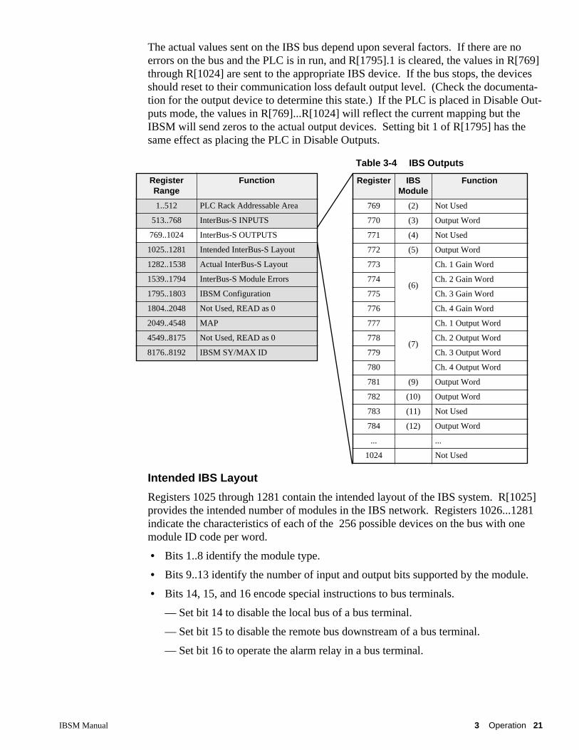
The actual values sent on the IBS bus depend upon several factors. If there are noerrors on the bus and the PLC is in run, and R[1795].1 is cleared, the values in R[769]through R[1024] are sent to the appropriate IBS device. If the bus stops, the devicesshould reset to their communication loss default output level. (Check the documenta-tion for the output device to determine this state.) If the PLC is placed in Disable Out-puts mode, the values in R[769]...R[1024] will reflect the current mapping but theIBSM will send zeros to the actual output devices. Setting bit 1 of R[1795] has thesame effect as placing the PLC in Disable Outputs.
Intended IBS Layout
Registers 1025 through 1281 contain the intended layout of the IBS system. R[1025]provides the intended number of modules in the IBS network. Registers 1026...1281indicate the characteristics of each of the 256 possible devices on the bus with onemodule ID code per word.
• Bits 1..8 identify the module type.
• Bits 9..13 identify the number of input and output bits supported by the module.
• Bits 14, 15, and 16 encode special instructions to bus terminals.
— Set bit 14 to disable the local bus of a bus terminal.
— Set bit 15 to disable the remote bus downstream of a bus terminal.
— Set bit 16 to operate the alarm relay in a bus terminal.
RegisterRange
Function
1..512 PLC Rack Addressable Area
513..768 InterBus-S INPUTS
769..1024 InterBus-S OUTPUTS
1025..1281 Intended InterBus-S Layout
1282..1538 Actual InterBus-S Layout
1539..1794 InterBus-S Module Errors
1795..1803 IBSM Configuration
1804..2048 Not Used, READ as 0
2049..4548 MAP
4549..8175 Not Used, READ as 0
8176..8192 IBSM SY/MAX ID
Register IBSModule
Function
769 (2) Not Used
770 (3) Output Word
771 (4) Not Used
772 (5) Output Word
773 Ch. 1 Gain Word
774 Ch. 2 Gain Word
775 Ch. 3 Gain Word
776
(6)
Ch. 4 Gain Word
777 Ch. 1 Output Word
778 Ch. 2 Output Word
779 Ch. 3 Output Word
780
(7)
Ch. 4 Output Word
781 (9) Output Word
782 (10) Output Word
783 (11) Not Used
784 (12) Output Word
... ...
1024 Not Used
Table 3-4 IBS Outputs

22 Operation 3 IBSM Manual
When the local or remote bus outputs of a bus terminal are disabled, the module willignore the entries in the intended layout corresponding to the isolated modules. It isnot necessary to modify the intended layout to reflect the truncated system configura-tion. The actual layout registers will describe the truncated configuation. Do not dis-able the remote bus output of the last bus termianl. The same commands can be trans-mitted to a non-bus terminal modules but are normally ignored.
Actual IBS Layout
Registers 1282 through 1538 contain the actual layout of the IBS system. R[1282]provides the actual number of modules in the IBS network. Registers 1283...1538 in-dicate each of the 256 possible devices on the bus with one module ID code per word.
• Bits 1..8 identify the module type.
• Bits 9..13 identify the number of input and output bits supported by the module.
• Bits 14, 15, and 16 show module messages when the bus is properly connected.
RegisterRange
Function
1..512 PLC Rack Addressable Area
513..768 InterBus-S INPUTS
769..1024 InterBus-S OUTPUTS
1025..1281 Intended InterBus-S Layout
1282..1538 Actual InterBus-S Layout
1539..1794 InterBus-S Module Errors
1795..1803 IBSM Configuration
1804..2048 Not Used, READ as 0
2049..4548 MAP
4549..8175 Not Used, READ as 0
8176..8192 IBSM SY/MAX ID
Reg. IBSModule
Value(hex)
Value(dec)
Description
1025 000C 12 # of modules
1026 (1) 0034 IBS 24 BK-T
1027 (2) xx96 IBS 24 DI/LC
1028 (3) xx95 IBS 24 DO/LC
1029 (4) xx0F IBS 24 BK-I/O-T
1030 (5) xx96 IBS 24 DI/LC
1031 (6) xx43 IBS AI
1032 (7) xx41 IBS AO 1
1033 (8) 0034 IBS 24 BK-T
1034 (9) xx95 IBS 24 DO/LC
1035 (10) xx95 IBS 24 DO/LC
1036 (11) xx96 IBS 24 DI/LC
1037 (12) xx95 IBS 24 DO/LC
... ... ...
1024 ... 0 0 ...
Table 3-5 Intended IBS Layout
IBSM Manual 3 Operation 23
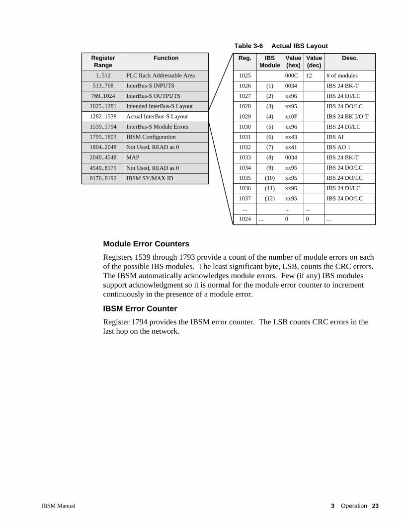
Module Error Counters
Registers 1539 through 1793 provide a count of the number of module errors on eachof the possible IBS modules. The least significant byte, LSB, counts the CRC errors. The IBSM automatically acknowledges module errors. Few (if any) IBS modulessupport acknowledgment so it is normal for the module error counter to incrementcontinuously in the presence of a module error.
IBSM Error Counter
Register 1794 provides the IBSM error counter. The LSB counts CRC errors in thelast hop on the network.
RegisterRange
Function
1..512 PLC Rack Addressable Area
513..768 InterBus-S INPUTS
769..1024 InterBus-S OUTPUTS
1025..1281 Intended InterBus-S Layout
1282..1538 Actual InterBus-S Layout
1539..1794 InterBus-S Module Errors
1795..1803 IBSM Configuration
1804..2048 Not Used, READ as 0
2049..4548 MAP
4549..8175 Not Used, READ as 0
8176..8192 IBSM SY/MAX ID
Reg. IBSModule
Value(hex)
Value(dec)
Desc.
1025 000C 12 # of modules
1026 (1) 0034 IBS 24 BK-T
1027 (2) xx96 IBS 24 DI/LC
1028 (3) xx95 IBS 24 DO/LC
1029 (4) xx0F IBS 24 BK-I/O-T
1030 (5) xx96 IBS 24 DI/LC
1031 (6) xx43 IBS AI
1032 (7) xx41 IBS AO 1
1033 (8) 0034 IBS 24 BK-T
1034 (9) xx95 IBS 24 DO/LC
1035 (10) xx95 IBS 24 DO/LC
1036 (11) xx96 IBS 24 DI/LC
1037 (12) xx95 IBS 24 DO/LC
... ... ...
1024 ... 0 0 ...
Table 3-6 Actual IBS Layout

24 Operation 3 IBSM Manual
IBSM Option Register
Register 1795 provides a bit map of various options for the IBSM.
• Bit 1 - Set to disable InterBus outputs. Clear if outputs should follow image regis-ters, error conditions permitting. The output image registers 769 through 1024 re-main active.
• Bit 2 - Set if IBSM is allowed to attempt reconfiguration (and set appropriatedownstream disable bits in the intended layout) when bus segments are missing ornot responding.
• Bit 3 - Set if IBSM should initiate reconfiguration (by clearing all downstream dis-able bits in the intended layout) when a reconfigure request is received from a busterminal.
• Bit 4 - Set if bus is allowed to run when a module error is active.
• Bit 5 - Set if inputs from IBS freeze on loss of communication. If clear, inputs arereset on loss of communication.
• Bit 6 - Set if the IBSM should not attempt to recover after a bus halt. If set,R[1795].1 must be set and then cleared to restart a bus halted by an error. If clear,the IBSM will automatically switch the bus from halt to run anytime it is possibleto do so.
• Bit 7 - Set if IBSM should NOT generate PLC bus faults when the IBS is halted.
• Bit 14 - Set if IBSM PLUS setup protection is enabled. If this bit is ON then theIBSM PLUS must be halted before it accepts configuration changes through theSY/MAX serial port or through the backplane. The Password Registers 1806 and1807 control access to this options register.
• Bit 15 - Set if DEA special support is required. Consult the Factory for more info.
• Bit 16 - Set if IBSM should run continuous ID cycles. This is intended for factorytesting. Users should Set 1795.1
RegisterRange
Function
1..512 PLC Rack Addressable Area
513..768 InterBus-S INPUTS
769..1024 InterBus-S OUTPUTS
1025..1281 Intended InterBus-S Layout
1282..1538 Actual InterBus-S Layout
1539..1794 InterBus-S Module Errors
1795..1803 IBSM Configuration
1804..2048 Not Used, READ as 0
2049..4548 MAP
4549..8175 Not Used, READ as 0
8176..8192 IBSM SY/MAX ID
Register IBS Module
1539 Module 1
1540 Module 2
1541 Module 3
1542 Module 4
... ...
1793 Module 256
1794 IBSM Error
Table 3-7 IBS Module Errors

IBSM Manual 3 Operation 25
CRC Error Limit
Register 1796 sets the number of consecutive CRC errors that will halt the bus andsignal the PLC CPU.
COMM Parameters
Register 1797 controls the configuration of the RS-422 SY/MAX port.
• Bits 1,2,3,4 - These bits determine the baud rate of the SY/MAX port. See Table3-9.
• Bit 9 - Set for no parity, clear for even parity.
• Bit 10 - Set for two-byte CRC, clear for one-byte BCC error checking.
Table 3-9 COMM Port Baud Rates
Any other value will select 9600 baud.
RegisterRange
Function
1..512 PLC Rack Addressable Area
513..768 InterBus-S INPUTS
769..1024 InterBus-S OUTPUTS
1025..1281 Intended InterBus-S Layout
1282..1538 Actual InterBus-S Layout
1539..1794 InterBus-S Module Errors
1795..1803 IBSM Configuration
1804..2048 Not Used, READ as 0
2049..4548 MAP
4549..8175 Not Used, READ as 0
8176..8192 IBSM SY/MAX ID
Register Description
1795 IBSM Options
1796 Module Error Limit
1797 COMM Parameters
1798 IBSM Status
1799 IBS "Health"
1800 Misc. IBSM Errors
1801 IBS Scan Time
1802 Ring Word Size
1803 Failed Terminal Number
Table 3-8 IBSM Configuration
Bit Pattern4321
Baud Rate Bit pattern4321
Baud Rate
0000 50 0111 1200
0001 75 1000 1800
0010 110 1001 2400
0011 134.5 1011 4800
0100 150 1100 7200
0101 300 1101 9600
0110 600 1111 19200
26 Operation 3 IBSM Manual
IBSM Status Register
Register 1798 displays the status of the IBS network.
• Bit 1 - Set if IBS ID cycles show the ring is complete.
• Bit 2 - Set if IBS layout matches intended system layout.
• Bit 3 - Set if IBS is running and outputs are valid on all modules.
• Bit 4 - Set if IBS is running and inputs from the bus are valid.
• Bit 7 - Set if there is a failure in the remote bus. Register 1803 displays the lastfunctioning bus terminal.
• Bit 8 - Set if there is a failure in the local bus. Register 1803 displays the lastfunctioning bus terminal.
• Bit 9 - Set if any module reports a module error.
• Bit 10 - Set if any module requests reconfiguration. If R[1795[.2 is clear, bitR[1798].10 must be cleared by the host.
• Bit 11 - Set if bus is halted because of timeouts, as from an open cable.
• Bit 12 - Set if bus is halted because of module CRC errors.
• Bit 13 - Set if bus is halted because of last hop CRC errors.
• Bit 14 - Set if map is too complex for minimum latency.
Register 1810 provides a "sticky" version of the error bits of register 1798.
IBS Health Register
Register 1799 provides a "Health" value for the network. The value ranges from 0 to1000 with 1000 being the best. This is the number of the last 1000 scans that wereerror free.
Miscellaneous IBSM Errors
Register 1800 provides additional IBSM error messages.
• Bit 1 - CPU error.
• Bit 2 - ROM error.
• Bit 3 - RAM error.
• Bit 4 - Illegal parameter in intended layout.
• Bit 5 - InterBus interface failure.
• Bit 6 - Illegal register number in map.
IBS Scan Time
Register 1801 provides the scan time for the IBS network in tenths of milliseconds.
IBS Ring Word Size
Register 1802 provides the number of 16 bit data words in the IBS ring. This valuedoes not include loopback or CRC words.

IBSM Manual 3 Operation 27
Failed Terminal Number
Register 1803 provides the ordinal number of the bus terminal with a failed down-stream remote or local bus. R[1798].7 or R[1798].8 will be set to indicate the type offailure. R[1803] will be zero if there is no error.
Layout Checksum
Register 1804 provides a checksum value for the Intended Layout of the IBSM PLUS. The returned value may be used to provide the PLC with a verification that the IBSMis properly configured.
Map Checksum
Register 1805 provides a checksum value for the Map of the IBSM PLUS. The re-turned value may be used to provide the PLC with a verification that the IBSM isproperly configured.
Module Protection Password
The IBSM PLUS has simple password protection of the "Options Register" in regis-ter 1795. Register 1807 stores the password. If there is a password stored, reads ofregister 1807 return with the value -1; otherwise a value of 0 is returned. Access tothe options register 1795 is prohibited when a password is stored. To remove thepassword protection write the stored password value to register 1806.
Most Recent CRC Error Number
Register 1808 provides the ordinal number of the bus terminal which most recentlyreported a CRC error. A value of 255 indicates that the IBSM itself reported the CRCerror on the last hop.
Most Recent Module Error Number
Register 1809 provides the ordinal number of the bus terminal which most recentlyreported a Module error.
"Sticky" Module Status
Register 1810 provides a time extended version of register 1798. When bits 7, 8, 9,11, 12, or 13 are set in register 1798, the entire register contents of 1798 are copied toregister 1810. The value in register 1810 is held until 1 second after the last error bitis cleared. This register is used for applications where the PLC might miss a quicktransition of an error bit.
Aditional Statistical Registers
Registers 8000 through 8005 provided additional statistical counters fortroubleshooting systems.

28 Operation 3 IBSM Manual
Table 3-10 Additional Statistical Counters
MAP
Registers 2049 through 4548 constitute the Mapper. There are 500 five register en-tries available for use. The entries are composed of 5 consecutive registers in the fol-lowing order:
• Map FROM register. Zero indicates the end of the map.
• Map TO register.
• Register Count.
• Bit mask. 1 to disable a bit.
• Rotate count. 0..15. Rotate each word left before masking.
The Mapper is capable of mapping any internal register to almost any other internalregister. If the target register is in the rack addressable area, the Mapper will convertthe register from a PLC output to a PLC input. It is reasonable to have multiple targetsfrom the same source. Care must be exercised when mapping multiple sources to asingle target. Multiple source mappings are best performed at the bit level using therotation and masking features. Several suggested mapping are shown below.
• Map PLC outputs to IBS outputs.
• Map IBS inputs to PLC inputs.
• Map IBS inputs to IBS outputs.
• Map IBSM status registers to PLC inputs.
• Map PLC outputs to IBSM control registers.
Register Counter
8000 Loop Error Counter
8001 Maximum consecutive scans with loop errors
8002 Not Used
8003 Timeout Error Counter
8004 INTL (internal no-send Error Counter
8005 SLER Error Counter

IBSM Manual 3 Operation 29
Communication Port Number
Register 8176 provides a mechanism for determining the port used to communicatewith the IBSM. A value of 0 indicates the COMM port. A value of 1 indicates read-ing from a Slave port.
NR&D ASCII ID
Registers 8177 through 8186 provide the module identification and firmware revisionin a packed ASCII format.
Register 8188 is always set to a constant hex value 9990.
RegisterRange
Function
1..512 PLC Rack Addressable Area
513..768 InterBus-S INPUTS
769..1024 InterBus-S OUTPUTS
1025..1281 Intended InterBus-S Layout
1282..1538 Actual InterBus-S Layout
1539..1794 InterBus-S Module Errors
1795..1803 IBSM Configuration
1804..2048 Not Used, READ as 0
2049..4548 MAP
4549..8175 Not Used, READ as 0
8176..8192 IBSM SY/MAX ID
Register MapEntry
Description
2049 Map FROM reg.
2050 Map TO register
2051 Register Count
2052 Bit Mask
2053
1
Rotate Count
2054 Map FROM reg.
2055 Map TO register
2056 Register Count
2057 Bit Mask
2058
2
Rotate Count
... ... ...
4548 500 Rotate Count
Table 3-11 Mapper


IBSM Manual 4 Configuration Software IBSMSW 31
4
Configuration Software IBSMSW
The IBSMSW software program is provided free of charge to IBSM users. This soft-ware is used to help configure the operation of the IBSM.
Data Entry KeysWhenever data entry is allowed by the program, certain keys can be used to facilitatedata entry. They are:
BACKSPACE Move cursor left and remove character there
LEFT ARROW Move cursor to the left one character
RIGHT ARROW Move cursor to the right one character
DEL Remove the character under the cursor
INS Change between insert and overstrike modes of entry
HOME Move cursor to the left edge of the field
END Move cursor to the end of the data
Control-F Move cursor right (Forward) one word
Control-R Move cursor left (Reverse) one word
Control-D Delete from the cursor to the end of the field
Control-U Delete from cursor to the beginning of the field
Control-Y Delete all characters in the field
ESC Exit the field without modifying it
ENTER Accept the contents of the field
When a field is opened for input, the cursor is positioned at the left side of the field. Ifdata is already present in the field, typing any character other than those listed abovewill cause the field to be blanked allowing entry of new data without first deleting the

32 Configuration Software IBSMSW 4 IBSM Manual
old. If it is desired to retain the previous data for editing, make sure the first key youtype is an editing key such as a left or right arrow.
Main MenuThe startup screen of IBSMSW is shown in Figure 4-1. The operational modes are se-lected by the highlighted menu bar on the fourth line. Selection can be made by mov-ing the cursor to the desired option using the arrow keys and pressing ENTER. Ashort cut is provided, simply type "N" for oNline, "F" for oFfline, "U" for Utility, "S"for setup or "Q" to quit.
Figure 4-1 Main Menu Screen
oNlineThe oNline selection provides a sub-menu for dynamically Editing the parameters orfor Printing the parameters from the module.
Edit Configuration
Upon selection of Edit, IBSMSW attempts to connect to the IBSM using the Setup pa-rameters defined in the Sy/Max Setup menu. For oNline Edit to function properly, allsetup parameters must be correct for the equipment used including the baud rate, par-ity, checksum, and route. For more information on the Sy/Max Setup parameters seepage 31.
Once IBSMSW has been able to connect to an IBSM, the screen should look some-thing like Figure 4-3. The TX and RX lights over the RS-422 port will be flashing anthe small line in the upper right corner of the screen should be spinning. WhileoNline, IBSMSW is continuously polling the IBSM and displaying the parameters onthe screen. If any parameters are changed, the effect will be immediate and the mo-dem will react according to the change. It is important to realize this, as changes madeto parameters such as the mode, parity, baud rate, etc. may result in the loss of com-munication to the IBSM.

IBSM Manual 4 Configuration Software IBSMSW 33
Figure 4-2 oNline Menu
Figure 4-3 oNline Edit
The block cursor is moved about the screen using the arrow keys on the keyboard. In-dividual parameters may be modified by toggling through the permitted parametersusing the -. +, and space bar. Parameters requiring direct value entry, such as the I/OMap table entries, may be edited with the commands listed on page 31. Several Func-tion keys are active while in the online screens and are described below:
• F1 Print - The F1 Function key will allow a direct printing of the screen to aprinter or ASCII file. A window will open in the middle of the screen promptingfor the destination of the print. The target may be a DOS device may be such as"LPT1" etc. or to an ASCII text file by entering a filename. Pressing Escape willabort the print screen.
• F3 Layout - The F3 Function key provides access to the Intended Layout of theIBS.
• F5 Map - The F5 Function key provides access to the I/O Map table.
• F9 SY/MAX Setup - The F9 Function key will bring up the SY/MAX Setup win-dow for immediate modification of the setup parameters of IBSMSW. PressingEscape will exit from the Setup window without making changes.

34 Configuration Software IBSMSW 4 IBSM Manual
• F10 Clear Error - When any Error Window appears with a beep, the F10 key maybe used to clear that error.
The opening screen of the oNline Edit provides a list of global parameters for theIBSM. Near the top of the center of the screen, the firmware revision of the IBSM isdisplayed. The date displayed in the upper right hand corner of the screen is the revi-sion of the IBSMSW software. The word ONLINE displayed below the IBSM firm-ware date indicates that this is an online connection. The Scan Time of the IBS net-work is dynamically displayed in the upper right hand corner of the screen.
The Disable outputs item allows an immediate disabling of the outputs on the IBS. Setting this value to YES causes R[1795].1 to be set in the IBSM. Setting this valueto NO causes this bit to be cleared. The default value is NO.
The Auto reconfigure on error item allows the IBSM to attempt reconfiguration (andset the appropriate downstream disable bits in the intended layout) when bus segmentsare missing or not responding. Setting this value to YES causes R[1795].2 to be set inthe IBSM. Setting this value to NO causes this bit to be cleared. The default value isNO.
The Restore configuration on Reconifig Request item allows the IBSM to initiatereconfiguration (by clearing all downstream disable bits in the intended layout) when areconfigure request is received from a bus terminal. Setting this value to YES causesR[1795].3 to be set in the IBSM. Setting this value to NO causes this bit to be cleared. The default value is NO.
The Allowed to run with module errors active item determines whether the IBS net-work continues to run when a module error is active. Setting this value to YES causesR[1795].4 to be set in the IBSM. Setting this value to NO causes this bit to be cleared.The default value is NO.
The Inputs on loss of communications item determines the state of the IBS input reg-isters in the IBSM upon loss of communication on the IBS network. If set to CLEAR,registers 513..768 will be set to zero upon loss of communication on the IBS network. If set to FREEZE, the registers 513..768 will remain unchanged. Setting this value toFREEZE causes R[1795].5 to be set in the IBSM. Setting this value to CLEAR causesthis bit to be cleared. The default value is CLEAR.
The Auto restart after error halt item determines whether the IBSM should attemptto recover after an IBS bus halt. If set to NO, IBSM R[1795].1 must be set and thencleared to restart an IBS bus halted by an error. If set to YES, the IBSM will auto-matically switch the bus from halt to run anytime it is possible to do so. Setting thisvalue to NO causes R[1795].6 to be set in the IBSM. Setting this value to YES causesthis bit to be cleared. The default value is YES.
The Stop PLC on error item determines whether the IBSM should generate a PLCbus error to stop the PLC after an IBS bus halt. If set to NO, the IBSM will not gener-ate a bus fault when the IBS is halted. Setting this value to NO causes R[1795].7 tobe set in the IBSM. Setting this value to YES causes this bit to be cleared. The defaultvalue is YES.
The Consecutive CRC errors to halt on item determines the number of consecutiveIBS network errors required stop the IBS bus. The default value is 32.

IBSM Manual 4 Configuration Software IBSMSW 35
The Serial port baud rate determines the setting for the SY/MAX COMM port onthe IBSM. Care should be taken in changing this value as its setting is immediatelychanged and a loss of communication from the personal computer may occur. Theavailable settings are 50, 75, 110, 134.5, 150, 300 ,600, 1200, 1800, 2400, 4800, 7200,9600, and 19200. The default setting is 9600.
The Serial port parity determines the setting for the SY/MAX COMM port on theIBSM. Care should be taken in changing this value as its setting is immediatelychanged and a loss of communication from the personal computer may occur. Theavailable settings are EVEN and NONE. The default value is EVEN.
The Sy/Max error check determines the setting for the SY/MAX COMM port on theIBSM. Care should be taken in changing this value as its setting is immediatelychanged and a loss of communication from the personal computer may occur. Theavailable settings are BCC and CRC. The default value is BCC.
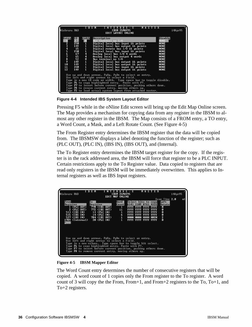
Pressing the F3 Function key while online allows the editing of the intended InterBus-S system layout. The screen should appear something like Figure 4-4.
The Entry column denotes the IBS module in the network. The ID column is thedecimal value of the Module Identification and this value is usually located on the IBSmodule. Each IBS module will have an entry, even if it has a 0 width such as a BK-Tbus terminal.
The Width column identifies the number of registers of data in the IBS module. Some devices will have a zero width, such as a BK-T bus terminal, other devices mayhave 1, 2, 4, or more registers of data. All IBS modules have the same number ofinput and output registers, regardless if they are used. A 16 bit digital input module, a16 bit digital output module, and a module with 16 bits of input and 16 bits of outputall have a width of 1.
The Description column provides a brief description of the IBS module based uponthe ID and the Width values.
The Disable column allows individual modules to be disabled from the IBS layout. When a module is disabled, its inputs represented in the IBSM are set to zero and itsoutputs are also set to zero.
The F6, F7, and F8 keys are used for copying, inserting, and removing lines from thelist. The F2 key may be pressed to load a copy of the actual IBS layout into the in-tended layout.
36 Configuration Software IBSMSW 4 IBSM Manual
Figure 4-4 Intended IBS System Layout Editor
Pressing F5 while in the oNline Edit screen will bring up the Edit Map Online screen. The Map provides a mechanism for copying data from any register in the IBSM to al-most any other register in the IBSM. The Map consists of a FROM entry, a TO entry,a Word Count, a Mask, and a Left Rotate Count. (See Figure 4-5)
The From Register entry determines the IBSM register that the data will be copiedfrom. The IBSMSW displays a label denoting the function of the register; such as(PLC OUT), (PLC IN), (IBS IN), (IBS OUT), and (Internal).
The To Register entry determines the IBSM target register for the copy. If the regis-ter is in the rack addressed area, the IBSM will force that register to be a PLC INPUT. Certain restrictions apply to the To Register value. Data copied to registers that areread only registers in the IBSM will be immediately overwritten. This applies to In-ternal registers as well as IBS Input registers.
Figure 4-5 IBSM Mapper Editor
The Word Count entry determines the number of consecutive registers that will becopied. A word count of 1 copies only the From register to the To register. A wordcount of 3 will copy the the From, From+1, and From+2 registers to the To, To+1, andTo+2 registers.

IBSM Manual 4 Configuration Software IBSMSW 37
The Select Bits to copy entries determine which bits will be copied to the To register. If a bit is selected with a "Y", then that bit will be copied to the target register. If a"N" is selected, that bit will not be copied to the target. The default setting is that allbits will be copied. The mask will be applied to all words in the word count. If a LeftRotate is selected for that entry, the rotate will occur before the mask is applied.
The Left Rotate setting determines the number of bit positions that that each wordwill be rotated before masking. A setting of 0 disables the bit rotation. A setting of 1will move bits 1 to 2, 2 to 3, 3 to 4, ... 15 to 16, and 16 to 1. A setting of 8 will ex-change the LSB with the MSB. The Left Rotate will be performed before the mask, ifselected, is applied. If multiple words are selected in the Word Count, the Left Rotateis applied to each word as it is being copied.
Print Configuration
The Online Print Configuration feature allows a direct formatted printing of the pa-rameters in the IBSM. A serial connection to the IBSM is required. Once selected,window is opened to prompt the user for the target of the printout. This target may bea printer or an ASCII file. After selection of the target, the IBSMSW polls the IBSMfor its configuration parameters and sends them to the target device.
oFflineThe oFfline menu offers several choices for maintenance, storage, and retrieval ofIBSM configurations. The oFfline menu is shown in Figure 4-6. The oFfline menuitems perform their operations using a copy of IBSM setup parameters in the personalcomputer’s memory. This copy may not be related to the actual configuration in anIBSM that may be connected oNline. Any changes made in the oFfline Editing thatare needed to be transferred to a connected IBSM must be done with the Send memoryto module menu item.
Figure 4-6 oFfline Menu
Read from disk to memory
This function reads an IBSM configuration from disk into the computer’s memory. The file to be read should have been created by the "Write from memory to disk"function described below and must have a .IBS extension. When "Read from disk tomemory" is selected, a window will open and ask for the name of the file to read. Thebottom part of the screen will show a list of all files with the extension .IBS in the

38 Configuration Software IBSMSW 4 IBSM Manual
current directory. Any subdirectories, or drives, will be shown in square brackets. The parent directory (of which the current directory is a subdirectory) is shown by theword "parent" in square brackets. You may either type the name of the file to read oryou may use the arrow keys to move the highlight to the desired filename. PressingENTER with the highlight on a filename will select that file for reading. PressingENTER with the highlight positioned on a directory name (either a subdirectory or[parent]) will change the current directory to that directory and will show the .IBSfiles in the new directory. If there are more files than will fit on the screen, pressingthe right arrow with the highlight at the right edge of the screen will scroll the displaysideways to show more files. Typing the ESC key will return to the offline functionmenu without loading a file.
Write from memory to disk
This function saves a copy of the memory file to a disk file. "Write from memory todisk" uses the same point and shoot file selection described for "Read from disk tomemory" above. To create a new file you must type the name. The name should be avalid MS/DOS filename but should not include any path name or extension. The pro-gram will append an extension of .IBS to the name and the file will be placed in thedirectory which is shown in the bottom half of the screen. To create a file in a direc-tory other than the current one, use the arrow and ENTER keys to traverse the direc-tory tree until a listing of the desired directory is shown in the bottom half of thescreen. Then type in the file name and press ENTER. If you specify (either by typingor by pointing) a file that already exists, you will be prompted for approval before thatfile is overwritten.
Edit configuration in memory
The Edit selection brings up a screen similar to the oNline Edit screen. Use the editorin the normal fashion to make changes to the memory file. Upon completion of theediting, it is advised that the work be saved using the "Write from memory to disk"routine. Upon exiting the editor, the main IBSMSW menu will appear.
It is important to remember to save the file before exiting or the changes will not bemade.
Send memory to master
This function requires a physical connection from the computer to an IBSM. TheSY/MAX setup must be properly configured to allow oNline communication to theIBSM. When the "Send memory to master" selection is made, the configuration in thecomputer’s memory is immediately transferred to the IBSM.
Fetch memory from master
This function requires a physical connection from the computer to an IBSM. TheSY/MAX setup must be properly configured to allow oNline communication to theIBSM. When the "Fetch memory from master" selection is made, the configuration inthe IBSM is immediately transferred to the oFfline memory.
Print configuration in memory
This function will produce a report showing the current oFfline configuration parame-ters in the computer’s memory. When this function is selected, the user will be

IBSM Manual 4 Configuration Software IBSMSW 39
prompted for an output filename with the default value of PRN shown. To send thereport to the PRN device (normally the parallel printer port), simply press ENTER. To send the report to a different port or to a file, type the name and then press EN-TER. Online configurations may be printed with the F1 print screen key.
Delete configuration file
This function removes the selected IBSM source file from the disk. "Delete configu-ration file" uses the same point and shoot file selection described for "Read sourcefrom disk" above. The name should be a valid MS/DOS filename but should not in-clude any path name or extension. The program remove the file from the disk as wellas removing it from the bottom of the screen. To remove a file in a directory otherthan the current one, use the arrow and ENTER keys to traverse the directory tree un-til a listing of the desired directory is shown in the bottom half of the screen. Thentype in the file name and press ENTER.
Optimize map
This function inspects the map in memory and minimizes the number of entries in themapper for the most efficient IBS scan time possible. For example, if the map con-tained two entries like the following:
FROM = 517 TO = 8 COUNT = 2FROM = 519 TO = 10 COUNT = 1
The optimizer would change the map to one entry:
FROM = 517 TO = 8 COUNT = 3
Quit offline functions
Selecting this menu item will return the user to the main menu. Pressing the Escapekey will perform the same function.
UtilityThe Utility menu provides access to useful maintenance and testing functions of theIBSMSW software.
Figure 4-7 Utility Menu

40 Configuration Software IBSMSW 4 IBSM Manual
View registers
Selecting the View registers menu item will invoke a SY/MAX register dataviewer/modifier. This viewer continuously performs a block read of 20 registers anddisplays the contents of those registers in hex, unsigned integer, signed integer, andbinary. The status register associated with the data register is also displayed in hex. The register viewer is dependent on the values located in the SETUP Sy/Max menu. Mode, Baud rate, Parity, Route, etc. must be properly set for proper communication.
The Up and Down arrow keys are used to move from register to register.
The Page Up and Page Down keys move in increments of 10 registers.
The Left and Right arrows move from column to column on the same register.
This register viewer is highly useful in that it allows easy editing of the data in theregister being viewed. By pressing 0..9 in the decimal fields or 0..9, or A..F in the hexfield, an editing mode is entered. New data may be entered at this time. Pressing theEnter key or moving to a new field with the arrow keys will cause the new data to bewritten to the edited register. If the curser is located in the REGISTER column theblock of registers being viewed may be adjusted by entering a new register number. To edit the binary values, press HOME when on the binary field. Move the cursor tothe desired bit and enter a ’0’ or a ’1’ and press enter to accept.
Pressing the F9 key will invoke the SY/MAX Setup window for immediate access tothe personal computer’s communication parameters.
Pressing Esc will exit from the Register viewer and return to the main menu. PressingEsc while editing a data field will result in canceling the edit and the modified datawill not be written to the register.
The STAT field displays the status register associated with the data register. TheSTATUS field is a read only display and can not be modified by the Register Viewer. Two common values are E000 and A000. A000 is the hex representation that the PLCrecognizes as a PLC OUTPUT register. E000 is for a PLC INPUT register. This al-lows easy recognition of registers used by the IBSM as inputs and used by the PLC asoutputs.
Figure 4-8 View Registers

IBSM Manual 4 Configuration Software IBSMSW 41
Download New Firmware to IBSM
The Download new firmware to IBSM utility allows the field installation of upgradesprovided by Niobrara via the RS-422 serial port. To load new firmware into theIBSM, perform the following steps:
1 Remove power from the register rack.
2 Remove the IBSM from the register rack.
3 Locate the Load/Normal toggle switch on the back of the IBSM. (See Figure 4-9) Move this switch to the LOAD position.
4 Install the IBSM back into the register rack.
5 Apply power to the rack. The IBSM should perform its startup sequence and dis-play the messages TEST, ROM1, RAM1, LOAD. If the display does not showLOAD, remove power and check the setting of the LOAD/NORMAL switch.
6 Connect the personal computer to the COMM port of the IBSM. An SC902 cableprovides a convenient method for the RS-232<>RS-422 conversion. (See Figure4-10)
NOTE: It is important to directly connect the IBSM to the personal computer. The Firmware Download utility uses the same personal computer COM port as thenormal SY/MAX settings, but the baud rate, parity, and protocol is different. TheFirmware Download uses 19200 baud, NONE parity and a custom protocol that isnot SY/MAX compatible. It is not possible to download new firmware over nor-mal SY/NET networks.
IBSM
LOAD
NORMAL
CLEAR
Figure 4-9 IBSM Firmware Load Switch

42 Configuration Software IBSMSW 4 IBSM Manual
7 From IBSMSW’s main menu, select Utility, Download New Firmware to IBSM. A window prompting for the file to download will appear. Select the IBSM for astandard IBSM or IBSM2 for an IBSM PLUS and press Enter. (See Figure 4-11)
8 Wait for the firmware download to be completed. A message indicating comple-tion will be displayed on the personal computer.
9 After the completion of the download, remove power from the register rack.
10 Remove the IBSM from the rack.
11 Change the LOAD/NORMAL switch back to NORMAL.
12 Install the IBSM back into the register rack.
13 Connect power back to the register rack. The IBSM should go back through itsstartup checks and display OPEN, SLER, HALT, RUN, DSBL, or whatever it dis-played before the new firmware was downloaded.
IBSM
POWER
IBSM
SC902 Cable
Figure 4-10 IBSM Firmware Download

IBSM Manual 4 Configuration Software IBSMSW 43
Figure 4-11 Download Firmware
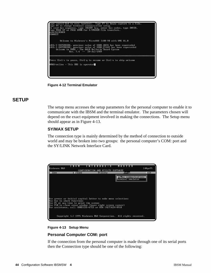
BBS Terminal Emulator
Selecting the BBS Terminal emulator from the Utilities menu will invoke a terminalemulator according to the setup selected in the Setup menu. The terminal emulatoropens as shown in Figure 4-12.
The terminal sends the ASCII code for the alpha-numeric characters out the selectedCOM port. Functions keys F1 through F4 and the keypad arrows send ANSI (i.e.VT100) codes. F7 is reserved for starting a file capture. F8 will close the capture file. The backspace key sends ASCII BS (08 hex). The Delete key sends and ASCII DEL(7F hex). The Insert key allows the transmission of ASCII hexadecimal characters di-rectly from the hex numbers separated by spaces.
The F9 key will invoke the Terminal Emulator Setup Screen for immediate modifica-tion of the personal computer’s communication setup parameters.
The BBS terminal displays printable ANSI ASCII characters which are received onthe port.
X/YMODEM transfers are supported within the BBS Terminal Emulator for ease offile transfers with the NR&D ONLINE BBS. At the point of transferring the file,press the PAGE UP key to have the personal computer send the file to the BBS orpress the PAGE DOWN key to have the personal computer receive the file from theBBS.
44 Configuration Software IBSMSW 4 IBSM Manual
Figure 4-12 Terminal Emulator
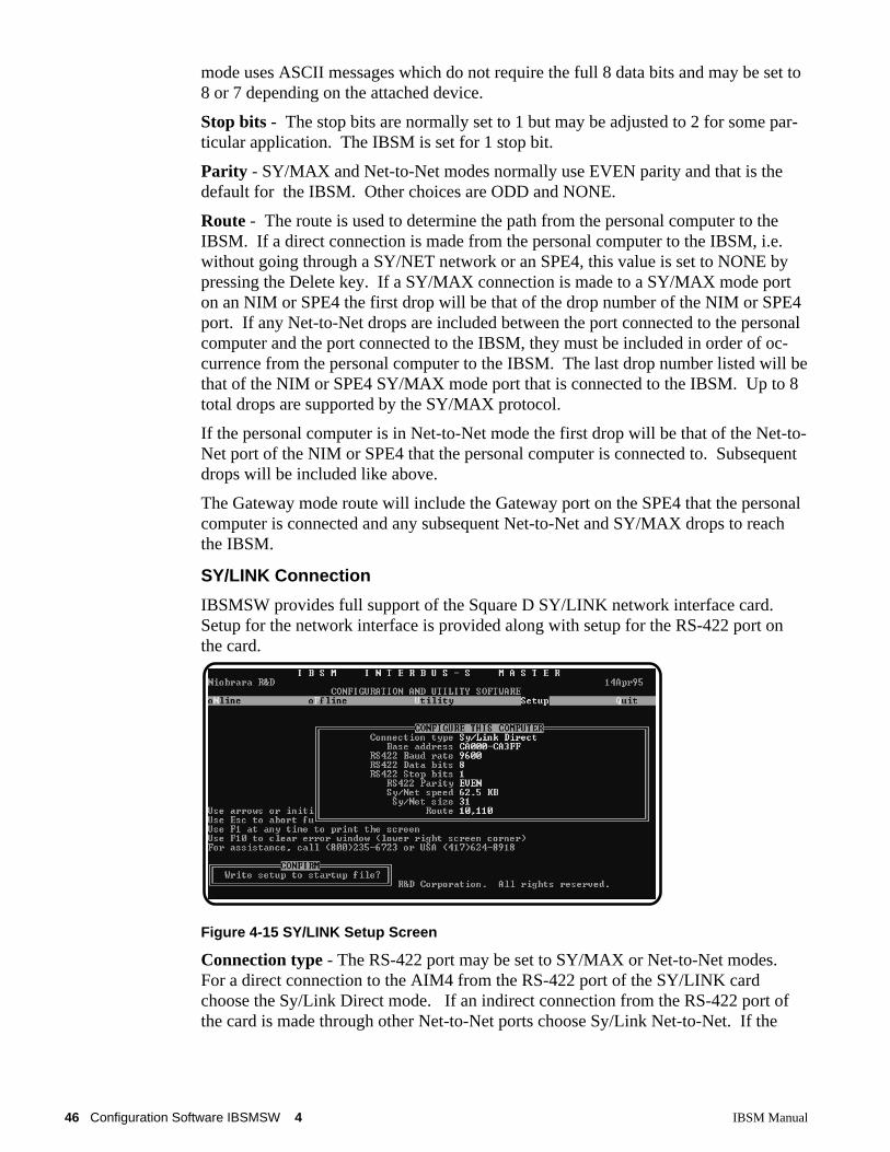
SETUPThe setup menu accesses the setup parameters for the personal computer to enable it tocommunicate with the IBSM and the terminal emulator. The parameters chosen willdepend on the exact equipment involved in making the connections. The Setup menushould appear as in Figure 4-13.
SY/MAX SETUP
The connection type is mainly determined by the method of connection to outsideworld and may be broken into two groups: the personal computer’s COM: port andthe SY/LINK Network Interface Card.
Figure 4-13 Setup Menu
Personal Computer COM: port
If the connection from the personal computer is made through one of its serial portsthen the Connection type should be one of the following:

IBSM Manual 4 Configuration Software IBSMSW 45
• Sy/Max COM:
• Net-to-Net COM:
• Gateway COM:
Sy/Max COM: is the default and most likely will be the one used. In this mode thepersonal computer will communicate through one of its COM: ports as though it werea SY/MAX device such as a PLC. The full SY/MAX protocol is supported includingrouting so SY/MAX COM: may be used through SY/MAX mode ports on NIMs andSPE4s with appropriate routing. This mode is to be used when a direct connectionfrom the personal computer COM: port is made to the IBSM. In most cases an RS-232<>RS-422 conversion is required and the Niobrara SC406 (or SC902) cable makesthis conversion very convenient.
Net-to-Net COM: is used when connecting to a NIM or SPE4 that is set to Net-to-Netmode. The first drop number in the route will be that of the address of the NIM.
Gateway COM: is used when connecting to an SPE4 port that is in Gateway mode. For more information about Gateway mode see the SPE4 instruction manual.
Figure 4-14 SY/MAX Setup Screen
Port - When one of the COM: connection types is selected a particular port of the per-sonal computer must be selected. Available choices are: COM1:, COM2:, COM3:,and COM4:. Select the port which will be used to connect to the IBSM.
Baud rate - The Baud rate selected here is the baud rate of the personal computer se-rial port selected. This value should be set to match the device connected to the per-sonal computer. An IBSM has a default baud rate of 9600 and if a direct connectionis made to the IBSM this is the setting that should be made on the personal computer. If the baud rate of the IBSM has been changed this value may need to be adjusted.
Data bits - When in SY/MAX or Net-to-Net modes the data bits is required to be 8and may not be changed. The SY/MAX protocol requires 8 data bits. The Gateway
46 Configuration Software IBSMSW 4 IBSM Manual
mode uses ASCII messages which do not require the full 8 data bits and may be set to8 or 7 depending on the attached device.
Stop bits - The stop bits are normally set to 1 but may be adjusted to 2 for some par-ticular application. The IBSM is set for 1 stop bit.
Parity - SY/MAX and Net-to-Net modes normally use EVEN parity and that is thedefault for the IBSM. Other choices are ODD and NONE.
Route - The route is used to determine the path from the personal computer to theIBSM. If a direct connection is made from the personal computer to the IBSM, i.e.without going through a SY/NET network or an SPE4, this value is set to NONE bypressing the Delete key. If a SY/MAX connection is made to a SY/MAX mode porton an NIM or SPE4 the first drop will be that of the drop number of the NIM or SPE4port. If any Net-to-Net drops are included between the port connected to the personalcomputer and the port connected to the IBSM, they must be included in order of oc-currence from the personal computer to the IBSM. The last drop number listed will bethat of the NIM or SPE4 SY/MAX mode port that is connected to the IBSM. Up to 8total drops are supported by the SY/MAX protocol.
If the personal computer is in Net-to-Net mode the first drop will be that of the Net-to-Net port of the NIM or SPE4 that the personal computer is connected to. Subsequentdrops will be included like above.
The Gateway mode route will include the Gateway port on the SPE4 that the personalcomputer is connected and any subsequent Net-to-Net and SY/MAX drops to reachthe IBSM.
SY/LINK Connection
IBSMSW provides full support of the Square D SY/LINK network interface card. Setup for the network interface is provided along with setup for the RS-422 port onthe card.
Figure 4-15 SY/LINK Setup Screen
Connection type - The RS-422 port may be set to SY/MAX or Net-to-Net modes. For a direct connection to the AIM4 from the RS-422 port of the SY/LINK cardchoose the Sy/Link Direct mode. If an indirect connection from the RS-422 port ofthe card is made through other Net-to-Net ports choose Sy/Link Net-to-Net. If the

IBSM Manual 4 Configuration Software IBSMSW 47
RS-422 port is not used and the connection is make through the SY/NET network toanother NIM, the choice does not matter.
Base address - This is a hex value that represents the SY/LINK’s cards address rangeselected by DIP switches on the card. Select the same range that is set on the card.
RS422 Baud rate - Select the baud rate to match the external device, normally 9600.
RS422 Data bits - Select the data bits to match the external device, normally 8.
RS422 Stop bits - Select the stop bits to match the external device, normally 1.
RS422 Parity - Select the parity to match the external device, normally EVEN.
Sy/Net speed - Select to match the speed settings of the other devices on the SY/NET.
Sy/Net size - Select to match the setting on the other SY/NET devices.
Route - The first drop in the route defines the network address of the SY/LINKboard. Since the personal computer is connected to the SY/LINK card through theedge connector of the card, port 0, the drop number must start with 0. The remainingtwo digits of that drop should be selected not to match any other device on theSY/NET. For instance, there are three NIMs on the network addressed 01, 02, and 03. It seems logical to make the SY/LINK card be at address 04 so the first drop in theroute field will be 004. The next drop will be that of the NIM port connected to theIBSM, or another Net-to-Net port. If Sy/Link Direct was selected and the IBSM isconnected directly to the RS-422 port of the SY/LINK card the full route statementwould be 004, 104 as the RS-422 port is considered to be port 1.
Terminal Emulator SETUP
The Terminal Emulator setup allows an individual setup for the operation of the termi-nal emulator. For instance, this separate setup will allow COM1 to be used for theIBSM SY/MAX connection and COM2 to be used for a terminal emulator connection.
Figure 4-16 Terminal Emulator Setup Screen
Port - Available choices are: COM1:, COM2:, COM3:, and COM4:. Select the portwhich will be used to connect to the external device.
Baud rate - The Baud rate selected here is the baud rate of the personal computer se-rial port selected. This value should be set to match the device connected to the per-sonal computer.

48 Configuration Software IBSMSW 4 IBSM Manual
Data bits - Selects the number of data bits for the message packet. Choices are 8 or 7depending on the attached device.
Stop bits - The stop bits are normally set to 1 but may be adjusted to 2 for some par-ticular application.
Parity - Choices are EVEN, ODD, and NONE.
Command Line ParametersIBSMSW may be started from the DOS command line with a sequence of letterswhich represent the keystrokes necessary to perform any operation. This allows batchprocessing of various commands such as downloading of stored setup files. The spe-cial characters /R, /D, and /E refer to the Return key, Delete key, and Escape key re-spectively. The parameters are not case sensitive. The following example causes theIBSMSW software to Read a file named SAMPLE, and send it to the IBSM and thenquits. It is assumed that the IBSM is connected to the computer and the rest ofIBSMSW setup is correct.
>IBSMSW FRsample/RFSQ
Another way of changing the Setup is to copy the setup file to another name in DOS,then copy it back to IBSM.STP in the batch file before calling IBSMSW.

IBSM Manual 5 Connector Pinouts 49
5
Connector Pinouts
COMM RS-422 port on IBSM (DE9S with slide lock posts)
1 TX- transmit data (inverted) from IBSM to output device
2 TX+ transmit data (noninverted) from IBSM to output device
3 RX- receive data (inverted) from data source to IBSM
4 RX+ receive data (noninverted) from data source to IBSM
5 +5VDC for smart cable power
6 +5VDC for smart cable power
7 GND
8 GND
9 Shield ground. AC coupled to the chassis.
Figure 5-1 SY/MAX RS-422 Connector Pinout
543
21
98
76

50 Connector Pinouts 5 IBSM Manual
InterBus-S port on IBSM (DE9S with 4-40 jack sockets)
1 DO+ transmit data (noninverted) from IBSM to Remote device
2 DI+ receive data (noninverted) from Remote device to IBSM
3 COM isolated from the SY/MAX gnd.
4 No Connection
5 No Connection
6 DO- transmit data (inverted) from IBSM to Remote device
7 DI- receive data (inverted) from Remote device to IBSM
8 No Connection
9 Shield ground. AC coupled to the chassis.
Figure 5-2 InterBus-S Connector Pinout
543
21
98
76

IBSM Manual 6 Recommended Cabling 51
6
Recommended Cabling
SY/MAX Cabling required to configure an IBSMConfiguration register data may be downloaded from an MS-DOS personal computerinto the IBSM. The factory default configuration for the module in SY/MAX mode is9600 baud, 8 data bits, EVEN parity, 1 stop bit and BCC checksum. The correct ca-bling needs to be installed to connect the personal computer to an IBSM port.
IBSM to personal computer cabling
Connecting the RS-422 IBSM is very easy using Niobrara’s SC406 (or SC902) RS-232 to RS-422 converter cable. If the personal computer has a 25-pin RS-232 portthen no adapters are needed. If the personal computer has a 9-pin RS-232 port then aNiobrara SD034 25-pin to 9-pin adapter is needed for the SC406. The SC902 cablewill plug directly into the 9-pin port of the personal computer so no adapter is needed.
Note: The included power supply with the SC406 (or SC902) is not required whenconnecting to the IBSM. Pins 5 and 6 of the IBSM’s RS-422 port provide the +5VDCto power the smart cable. Pins 7 and 8 provide the GND return for the cable.

52 Recommended Cabling 6 IBSM Manual
Cabling required to connect a IBSM port to an external device
IBSM RS-422 to SY/MAX RS-422 port
This is a Niobrara DC1 cable.
InterBus-S Remote Network Cabling
Figure 6-1 InterBus-S Remote Cable
This is a Niobrara IR9D cable.
DE−9P DE−9P
1 pair 1 3
2 pair 1 4
3 pair 2 1
4 pair 2 2
5 5
6 6
7 7
8 8
9 shield 9
DE−9P (Remote OUT) DE−9S (Remote IN)
1 pair 1 1
6 pair 1 6
2 pair 2 2
7 pair 2 7
3 shield 3
5
9

IBSM Manual A IBSM Display Messages 53
Appendix A
IBSM Display Messages
In the following definitions, nnn is a three digit decimal number specifying the module(remote or local bus) that is having difficulty. To determine nnn, count the first busterminal, then its local bus modules from the bus terminal to the end of the local bus,then the next bus terminal, etcetera.
Cnnn - nnn is a three digit decimal number specifying the module (remote or localbus) which is reporting a CRC error. Modules are counted as described above. Look for bad cabling to or from the specified module, or a defective module.
CFIG - The actual system layout determined by the IBSM does not match the intendedlayout loaded by the user. One or more cables may be unplugged. Sometimesan Rnnn error will be displayed as CFIG because a cut cable shorts or capaci-tively couples the signal back along the cable.
CODE - The IBSM has detected a problem with its internal software.
CRCn - A module-to-module CRC error was detected as described under Cnnn abovebut the IBSM is unable to identify the offending module.
CRCM - A CRC error is being detected between the first remote bus module or busterminal and the IBSM. Output data may be valid but input data is zeroed.
DSBL - The PLC CPU is instructing the IBSM to hold physical outputs at zero, butretain the logical state. The IBSM is scanning the bus and outputting zeroes toall modules. Registers 769 through 1024 reflect the logical state of all outputs.
Ennn - nnn is a three digit decimal number specifying the module (remote or localbus) which is reporting an error. The IBSM is unable to identify the specificerror. Look for bad cabling to or from the specified module, or a defectivemodule.
ERAM - The IBSM has detected a RAM problem and is defective.
EROM - The IBSM has detected a ROM problem. The master may be defective or the field-reloadable firmware may be corrupt.
ER02 - The IBSM has detected a problem with the boot firmware and the master is

54 IBSM Display Messages A IBSM Manual
defective.
ER03 - The IBSM has detected a RAM memory error. The master is defective.
ER04 - The field-reloadable firmware is corrupted.
ERRn - A module is reporting an error is detected as described under Ennn above butthe IBSM is unable to identify the offending module or the specific error con-dition.
Hnnn - nnn is a three digit decimal number specifying the module (remote or localbus) which mismatches the IBSM’s intended network layout configuration. The error H001 is displayed when an unconfigured IBSM is connected to afunctional Interbus-S network.
HALT - The PLC CPU is instructing the IBSM to set its outputs to zeroes. The IBSMis scanning the bus and outputting zeroes to all modules. Registers 769through 1024 are zeroed.
IBSM - The IBSM is executing normal startup procedures.
INTL - The IBSM detected an internal error and may be defective.
Lnnn - nnn is a three digit decimal number specifying the bus terminal whose localbus the IBSM was unable to successfully connect. Look for a bad cable or de-fective module in the local bus attached to that bus terminal or a defective busterminal. The IBSM is not scanning and will attempt to restart the bus onceper second. If not disabled by 1795.7, the IBSM will signal the PLC CPU tohalt with an I/O or bus error.
LOAD - The LOAD/NORMAL switch is in the LOAD position and the IBSM is prepared to accept new firmware via the RS422 serial port.
LOOP - The loopback word received by the IBSM did not match the one sent.
LONG - The physical Interbus-S ring is longer than the 4096 bit limit. This error mayalso indicate a cable break with long cables.
Mnnn - nnn is a three digit decimal number specifying the module (remote or localbus) which is reporting a module error. Module nnn is probably withoutpower, has a blown fuse, a shorted output, or is defective. The meaning of amodule error is dependent on the module type. Consult the module’s docu-mentation. The will continue to scan the bus but, unless 1795.4 is set, outputswill be set to zero and, unless disabled by 1795.7, the PLC CPU will halt.
MODn - A module error is detected as described under Mnnn above but the IBSM is unable to identify the offending module.
OPEN - A cable is open between the IBSM and the first remote bus terminal. Thefirst bus terminal is defective, has an open fuse, or is not powered. The IBSMis not scanning and will attempt to restart the bus once per second. If not dis-abled by 1795.7, the IBSM will signal the PLC CPU to halt with an I/O or buserror.
PASS - The boot firmware has passed all self-tests and is about to start the master.
Rnnn - nnn is a three digit decimal number specifying the last remote bus module orbus terminal with which the IBSM is able to communicate. Look for a cableproblem between remote bus module nnn and nnn+1, no power or an open fusein module nnn+1, or a problem with one of those two modules. The IBSM is

IBSM Manual A IBSM Display Messages 55
not scanning and will attempt to restart the bus once per second. If not dis-abled by 1795.7, the IBSM will signal the PLC CPU to halt with an I/O or buserror.
ROM1 - The IBSM boot firmware is testing the boot ROM.
ROM2 - The IBSM boot firmware is testing the field reloadable firmware at start-up.
ROM3 - The IBSM boot firmware is testing the field reloadable firmware after a re-load.
RUN - The IBSM and the PLC CPU are running. Data is valid.
SLER - The SL test failed indicating a problem in the cabling,
TEST - The IBSM boot firmware is executing a self-test. If this message appears atany time except startup, check power supply voltages.
TOUT - The IBSM timed out waiting to receive data from the remote bus.
UDIS - Interbus-S outputs have been disabled by setting bit 1795.1 The mapper con-tinues to scan and output image registers 769 through 1024 continue to reflectthe map solution. The IBSM is scanning the ring and transferring zeroes (in-stead of the map solution) to all outputs.


IBSM Manual B NR&D Internet 57
Appendix B
NR&D Internet
Niobrara Research & Development is on the World Wide Web making it easy to bringthe user up to date on software revisions, firmware changes, product support news,and more. This Web service operates on a 24 hour a day basis and is accessible fromany personal computer equipped with an Internet conection. The address is:
www.niobrara.com
E-mail communication is also provided for technical support and marketing questions.


IBSM Manual Index 59
Index
A
Actual Layout, 22Allowed to run with errors, 34Auto reconfigure on Error, 34Auto Restart, 34
C
CFIG, 53Cnnn, 53CODE, 53COMM Port, 25CRCM, 53CRCn, 53CRC errors, 34
D
Disable Outputs, 34DSBL, 53
E
Ennn, 53ERAM, 53EROM, 53ERRn, 54ER02, 53ER03, 54ER04, 54EVEN, 46
F
Failed Terminal Number, 27Firmware REV, 34
H
HALT, 54
I
IBSM, 54IBSM Status Register, 26IBS Health, 26IBS Inputs, 20IBS Outputs, 20Inputs on loss of communications, 34Installation, 11Intended Layout, 21INTL, 54
L
Lnnn, 54LOAD, 11, 54LONG, 54LOOP, 54
M
Map, 28Mapper, 8Map Checksum, 27Mnnn, 54MODn, 54
N
NONE, 46
O
ODD, 46OPEN, 54Options, 24
P
PASS, 54Password, 27PLC Stop, 34

60 Index IBSM Manual
R
Rack Addressable Area, 19Restore configuration on Reconfig., 34Ring Word Size, 26Rnnn, 54ROM1, 55ROM2, 55ROM3, 55RUN, 55
S
Scan Time, 26, 34SLER, 55
T
TEST, 55TOUT, 55
U
UDIS, 55


