for Small Scale Distributed Generation (SSDG)ceb.intnet.mu/grid_code/document/gridc.pdf ·...
32
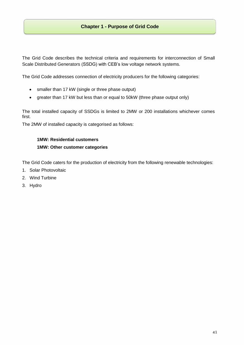
Central Electricity Board Grid Code for Small Scale Distributed Generation (SSDG) CEB’s pole PV module CEB’s Customer Wind turbine Grid Tie Inverter 9 th December 2010
Transcript of for Small Scale Distributed Generation (SSDG)ceb.intnet.mu/grid_code/document/gridc.pdf ·...

Central Electricity Board
Grid Code
for
Small Scale Distributed Generation
(SSDG)
CEB’s pole
PV module
CEB’s Customer
Wind turbine
Grid Tie Inverter
9 t h December 2010

2
Foreword
The purpose of this document is to assist the public to better understand the procedure for application, the requirements of the Grid Code, the Feed-in-Tariffs and other related issues regarding Small Scale Distributed Generation (SSDG).
Any prospective applicant willing to take advantage of the Small Scale Distributed Generation (SSDG) Scheme is informed that:
I. Compliance to this Grid Code is mandatory
II. The provisions of the Electricity Act shall be adhered to.

3
Chapter 1: Purpose of Grid Code .............................................................................................. 1
Chapter 2: Connecting SSDG to the grid .................................................................................. 2
Chapter 3:Grid Code requirements and Safety Aspects ....................................................... 3-13
Annex 1: Abbreviations and definitions .............................................................................. 14-15
Annex 2: Feed-in-Tariff (FIT) .................................................................................................. 16
Annex 3: CEB fees ................................................................................................................. 17
Annex 4: SSDG Application Form ...................................................................................... 18-20
Annex 5: SSDG Certificate of Installation ................................................................................ 21
Annex 6: SSDG Certificate of Commissioning ........................................................................ 22
Annex 7: SSDG Connection Agreement ............................................................................ 23-29
Table of Contents
4
The Grid Code describes the technical criteria and requirements for interconnection of Small
Scale Distributed Generators (SSDG) with CEB‟s low voltage network systems.
The Grid Code addresses connection of electricity producers for the following categories:
smaller than 17 kW (single or three phase output)
greater than 17 kW but less than or equal to 50kW (three phase output only)
The total installed capacity of SSDGs is limited to 2MW or 200 installations whichever comes first.
The 2MW of installed capacity is categorised as follows:
1MW: Residential customers
1MW: Other customer categories
The Grid Code caters for the production of electricity from the following renewable technologies:
1. Solar Photovoltaic
2. Wind Turbine
3. Hydro
Chapter 1 - Purpose of Grid Code
1
5
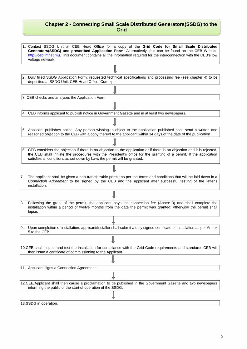
1. Contact SSDG Unit at CEB Head Office for a copy of the Grid Code for Small Scale Distributed Generators(SSDG) and prescribed Application Form. Alternatively, this can be found on the CEB Website
http://ceb.intnet.mu. This document contains all the information required for the interconnection with the CEB‟s low voltage network.
2. Duly filled SSDG Application Form, requested technical specifications and processing fee (see chapter 4) to be deposited at SSDG Unit, CEB Head Office, Curepipe.
3. CEB checks and analyses the Application Form.
4. CEB informs applicant to publish notice in Government Gazette and in at least two newspapers.
5. Applicant publishes notice. Any person wishing to object to the application published shall send a written and reasoned objection to the CEB with a copy thereof to the applicant within 14 days of the date of the publication.
6. CEB considers the objection.If there is no objection to the application or if there is an objection and it is rejected, the CEB shall initiate the procedures with the President‟s office for the granting of a permit. If the application satisfies all conditions as set down by Law, the permit will be granted.
7. The applicant shall be given a non-transferrable permit as per the terms and conditions that will be laid down in a Connection Agreement to be signed by the CEB and the applicant after successful testing of the latter‟s
installation.
8. Following the grant of the permit, the applicant pays the connection fee (Annex 3) and shall complete the installation within a period of twelve months from the date the permit was granted; otherwise the permit shall lapse.
9. Upon completion of installation, applicant/Installer shall submit a duly signed certificate of installation as per Annex 5 to the CEB.
10.CEB shall inspect and test the installation for compliance with the Grid Code requirements and standards.CEB will then issue a certificate of commissioning to the Applicant.
11. Applicant signs a Connection Agreement.
12.CEB/Applicant shall then cause a proclamation to be published in the Government Gazette and two newspapers informing the public of the start of operation of the SSDG.
13.SSDG in operation.
Chapter 2 - Connecting Small Scale Distributed Generators(SSDG) to the Grid

6
1.0 Design parameters
The SSDG will be connected to the 400/230 V system as described in Table 1 below. The
SSDG has to be functioning and protect itself within the range of the voltages, currents and
frequencies existing in the CEB‟s grid.
Description Range
Voltage 230/400 V ± 6 %
Short circuit Characteristics (1 sec) 18 kA, (50 Hz)
Nominal frequency 50 Hz
Statutory frequency deviation 50 Hz ±1.5 %
Operating frequency range 47 Hz – 52 Hz
Table 1: Normal operating parameters of the CEB’s low voltage grid
The CEB LV grid is designed as a TT system.
2.0 Protection requirements
2.1 Availability of protection
The applicant shall ensure that all equipment are protected and that all elements of the
protection, including associated inter-tripping, are available at all times. Unavailability of the
protection will require the SSDG plant to be taken out of service.
The SSDG shall be protected against
a. Overload.
b. Short circuit within the SSDG.
c. Earth faults in the LV grid close vicinity of the SSDG.
d. Over Current.
e. Abnormal voltages(Table 2 below)
f. Abnormal frequencies (Table 2 below)
g. Lightning.
h. Loss of mains.
2.2 DC Functions of protection apparatus
All protection apparatus functions shall operate down to a level of 50% of the nominal DC
supply voltage of the DC system, or the system must be able to safely disconnect and
shutdown when operation conditions are outside the nominal operating DC voltage specified
in the DC system specifications.
Chapter 3 - Grid Code Requirements and Safety Aspects

7
2.3 Protection flagging, indication and alarms
All protective devices supplied to satisfy the CEB‟s requirements shall be equipped with
operation indicators. Such indicators shall be sufficient to enable the determination of which
devices caused a particular trip.
Any failure of the applicant‟s tripping supplies, protection apparatus and circuit breaker trip
coils shall be alarmed within the applicant‟s installation, and the applicant shall be responsible
for prompt action to be taken to remedy such failure.
2.4 Trip settings
The trip settings must comply with the values stated inTable 2.
Parameter Symbol Trip setting Clearance time
Over voltage (a) U>> 230 V + 10 % 0,2 s
Over voltage U> 230 V + 6 % 1,5 s
Under voltage U< 230 V – 6 % 1,5 s
Over frequency (b) f> 50 Hz + 2 % 0,5 s
Under frequency f< 50 Hz - 6 % 0,5 s
Loss of mains df/dt Vector shift
2.5 Hz / s 10 degrees
0,5 s
Table 2: Default interface protection settings.
NOTE: Voltage and frequency is referenced to the Supply Terminals.
(a) If the SSDG can generate higher voltage than the trip setting, the step 2 over voltage is
required.
(b) The trip setting for over frequency is set lower than the maximum operating frequency
defined in Table 1 in order to avoid contribution of the SSDG to rising frequency.
2.5 Network islanding
The applicant shall not supply power to the CEB‟s network during any outages of the system.
The SSDG may only be operated during such outages to supply the applicant‟s own load
(isolated generation) with a visibly open tie to the CEB‟s network. The SSDG shall cease to
energise the CEB‟s network within 0.5 seconds of the formation of an island as shown in
Table 2.
2.6 Re-connection
Following a protection initiated disconnection, the SSDG is to remain disconnected from the
network until the voltage and frequency at the supply terminals has remained within the
nominal limits for at least 3 minutes. Automatic reconnection is only allowed when
disconnection was due to operating parameters being outside the normal operating range

8
stated in Table 2, not if disconnection was caused by malfunctioning of any devices within the
SSDG installation.
2.7 Synchronising AC generators
The SSDG shall provide and install automatic synchronizing. Check Synchronizing shall be
provided on all generator circuit breakers and any other circuit breakers, unless interlocked,
that are capable of connecting the SSDG plant to the CEB‟s network. Check Synchronising
Interlocks shall include a feature such that circuit breaker closure via the Check
Synchronising Interlock is not possible if the permissive closing contact is closed prior to the
circuit breaker close signal being generated.
2.8 Earthing requirements
Earthing shall be according to IEC 60364-5-55.
For systems capable of operating in isolated generation protection by automatic disconnection of supply shall not rely upon the connection to the earthed point of the public supply system. When a SSDG is operating in parallel with the CEB‟s network, there shall be no direct
connection between the cogenerator winding (or pole of the primary energy source in the
case of a PV array or Fuel Cells) and the CEB‟s earth terminal.
The winding of an a.c. generator must not be earthed. Note that a d.c. source or d.c.
generator could be earthed provided the inverter separates the a.c. and d.c. sides by at least
the equivalent of a safety isolating transformer. However, consideration would then need to
be given to the avoidance of corrosion on the d.c. side.
At the CEB‟s grid TT earthing system is normal. The neutral and earth conductors must be
kept separate throughout the installation, with the final earth terminal connected to a local
earth electrode.
Warning Notice that: “CONDUCTORS MAY REMAIN LIVE WHEN ISOLATOR IS OPEN”
shall be conspicuously displayed at the installation.
3.0 Power quality
3.1 Limitation of DC injection
The SSDG should not inject a DC current greater than the largest value of 20 mA and 0.25 %
of the rated AC output current per phase.
3.2 Limitation of voltage flicker induced by the SSDG
The SSDG installation shall not cause abnormal flicker beyond the limits defined by the
“Maximum Borderline of Irritation Curve” specified in the IEEE 519-1992.
3.3 Harmonics
Based on IEEE 519, the total harmonic distortion (THD) voltage shall not exceed 5.0% of the
fundamental on 400 V when measured at the point of common coupling (PCC).
9
The total harmonic distortion will depend on the injected harmonic current and the system
impedance seen from the PCC. However, in order to facilitate the fulfilment of the
requirements by e.g. inverter manufacturers, the voltage distortion limits have been translated
into a similar requirement on current distortion.
The SSDG system output should have low current-distortion levels to ensure that no adverse
effects are caused to other equipment connected to the utility system. The SSDG system
electrical output at the PCC should comply with Clause 10 of IEEE Std. 519-1992 and should
be used to define the acceptable distortion levels for PV systems connected to a utility. The
key requirements of this clause are summarized in the following:
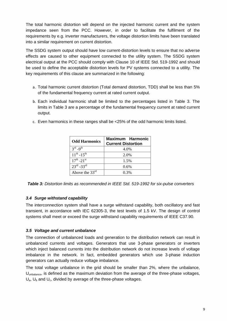
a. Total harmonic current distortion (Total demand distortion, TDD) shall be less than 5%
of the fundamental frequency current at rated current output.
b. Each individual harmonic shall be limited to the percentages listed in Table 3. The
limits in Table 3 are a percentage of the fundamental frequency current at rated current
output.
c. Even harmonics in these ranges shall be <25% of the odd harmonic limits listed.
Odd Harmonics Maximum Harmonic Current Distortion
3rd
-9th
4.0%
11th -15
th 2.0%
17th -21
st 1.5%
23rd
-33rd
0.6%
Above the 33rd
0.3%
Table 3: Distortion limits as recommended in IEEE Std. 519-1992 for six-pulse converters
3.4 Surge withstand capability
The interconnection system shall have a surge withstand capability, both oscillatory and fast
transient, in accordance with IEC 62305-3, the test levels of 1.5 kV. The design of control
systems shall meet or exceed the surge withstand capability requirements of IEEE C37.90.
3.5 Voltage and current unbalance
The connection of unbalanced loads and generation to the distribution network can result in
unbalanced currents and voltages. Generators that use 3-phase generators or inverters
which inject balanced currents into the distribution network do not increase levels of voltage
imbalance in the network. In fact, embedded generators which use 3-phase induction
generators can actually reduce voltage imbalance.
The total voltage unbalance in the grid should be smaller than 2%, where the unbalance,
Uunbalance, is defined as the maximum deviation from the average of the three-phase voltages,
Ua, Ub and Uc, divided by average of the three-phase voltages.

10
The contribution from one installation may not cause an increase of the voltage unbalance of
more than 1.3%.
When considering three phase units, the contribution to the voltage unbalance can be
described as
or
Where
SSC is the Three phase short circuit power
Ineg,seq,load is Negative sequence of component loads
Uline is the line voltage
Uunbalance the voltage unbalance
If nothing else is stated the Ssc shall be 2.5 MVA. The demand on voltage unbalance on a
three phase load can be translated into a demand on the maximum negative sequence
current.
3.6 Voltage step change
The process of starting an SSDG can sometimes cause step changes in voltage levels in the
distribution network. These step changes are caused by inrush currents, which may occur
when transformers or induction generators are energised from the network. Synchronous
generators do not give rise to inrush currents themselves, but their generator transformers
may do so if they are energised from the network. Step voltage changes will also occur
whenever a loaded generator is suddenly disconnected from the network due to faults or
other occurrences.
Step voltage changes caused by the connection and disconnection of generating plants at the
distribution level, should not exceed ±3% for infrequent planned switching events or outages
and ±6% for unplanned outages such as faults.
If the connection of the SSDG to the grid does not exceed the following values in Table 4 it is
expected to stay within the above mentioned voltage levels.
%100),,(
),,(),,(
cbaU
cbaUUUUMaxU
avg
avgcba
unbalance
AI loadseqneg 6.35.2
400%3.13,,max,
sc
lineloadseqneg
S
UI
][U3 %in unbalance,,
sc
lineloadseqneg
unbalanceS
UIU
,,3

11
Connection Inrush current
Single phase 19 A
Three phase 30 A
Table 4: Maximum inrush current
Where induction generators are used, as in fixed speed wind turbines, they shall be fitted with
„soft starters‟ These devices limit inrush currents to roughly the same level as the normal
rated current. This reduces the magnitude of the step voltage changes which occur on
starting.
4.0 Power factor
The power factor of the SSDG at normal operating conditions across the statutory range of
nominal voltage shall be between 0.95 leading and 0.95 lagging.
5.0 Safety, isolation and switching
5.1 Rules for working on low voltage (LV) grid
According to the CEB safety rules based on Occupational Safety and Health Act 2005, the
following rules must be respected before working on a LV grid:
a. The system must be isolated from all possible sources of supply, all switches must be
locked in visibly open positions, the system must be tested on the site of work, and the
system must be short-circuited.
b. The SSDG shall have a local means of isolation that disconnects all live conductors
including the neutral. The producer shall not energize a de-energized CEB‟s Power
circuit.
c. A switch shall be installed to disable the automatic or manual closing of the
interconnecting switch or breaker. This switch shall be accessible to the CEB‟s personnel
to obtain the necessary safety requirements when the CEB‟s personnel is working on
associated equipment or lines. While the CEB‟s personnel is working on the grid the
operation of switches shall not be possible for others than the CEB, which can be
assured by keeping the keys to lockable switches. Alternatively the CEB‟s personnel will
remove and keep fuses while working on lines.
d. In all instances the switch, which must be manual, must be capable of being secured in
the „off‟ isolating position. The switch must be located in an accessible position in the
producer‟s installation.
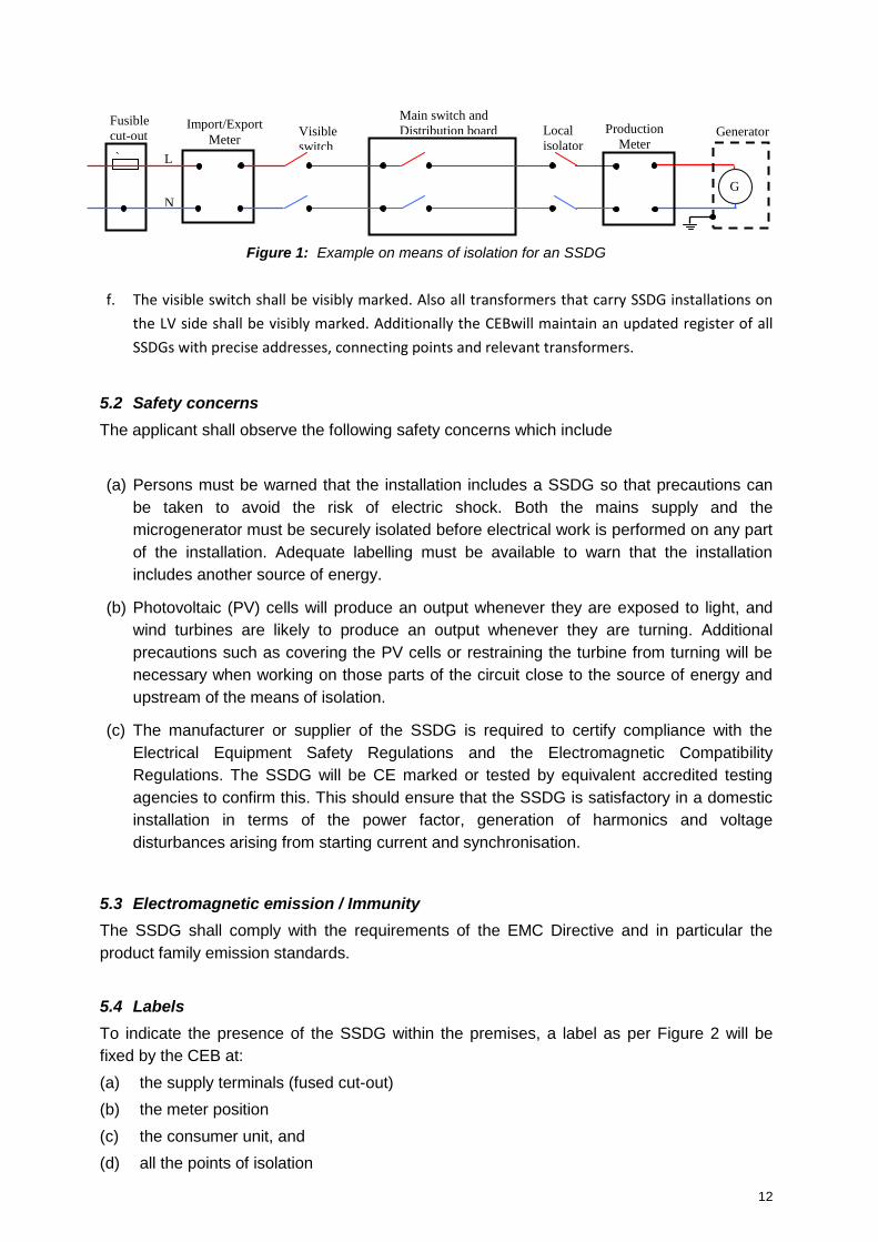
e. Isolation for an SSDG shall be as per Figure 1 below
12
Figure 1: Example on means of isolation for an SSDG
f. The visible switch shall be visibly marked. Also all transformers that carry SSDG installations on
the LV side shall be visibly marked. Additionally the CEBwill maintain an updated register of all
SSDGs with precise addresses, connecting points and relevant transformers.
5.2 Safety concerns
The applicant shall observe the following safety concerns which include
(a) Persons must be warned that the installation includes a SSDG so that precautions can
be taken to avoid the risk of electric shock. Both the mains supply and the
microgenerator must be securely isolated before electrical work is performed on any part
of the installation. Adequate labelling must be available to warn that the installation
includes another source of energy.
(b) Photovoltaic (PV) cells will produce an output whenever they are exposed to light, and
wind turbines are likely to produce an output whenever they are turning. Additional
precautions such as covering the PV cells or restraining the turbine from turning will be
necessary when working on those parts of the circuit close to the source of energy and
upstream of the means of isolation.
(c) The manufacturer or supplier of the SSDG is required to certify compliance with the
Electrical Equipment Safety Regulations and the Electromagnetic Compatibility
Regulations. The SSDG will be CE marked or tested by equivalent accredited testing
agencies to confirm this. This should ensure that the SSDG is satisfactory in a domestic
installation in terms of the power factor, generation of harmonics and voltage
disturbances arising from starting current and synchronisation.
5.3 Electromagnetic emission / Immunity
The SSDG shall comply with the requirements of the EMC Directive and in particular the
product family emission standards.
5.4 Labels
To indicate the presence of the SSDG within the premises, a label as per Figure 2 will be
fixed by the CEB at:
(a) the supply terminals (fused cut-out)
(b) the meter position
(c) the consumer unit, and
(d) all the points of isolation
`
G
Fusible
cut-out Import/Export
Meter Visible
switch
Main switch and
Distribution board Local
isolator Generator
L
N
Production
Meter
13
Figure 2:SSDG label
The installation operating instructions must contain the manufacturer‟s contact details e.g.
name, telephone number and web address.
5.5 Documentation
Up-to-date information must be displayed at the SSDG as follows:
(a) A circuit diagram showing the relationship between the SSDG and the CEB‟s fused cut-
out. This diagram is also required to show by whom the generator is owned and
maintained.
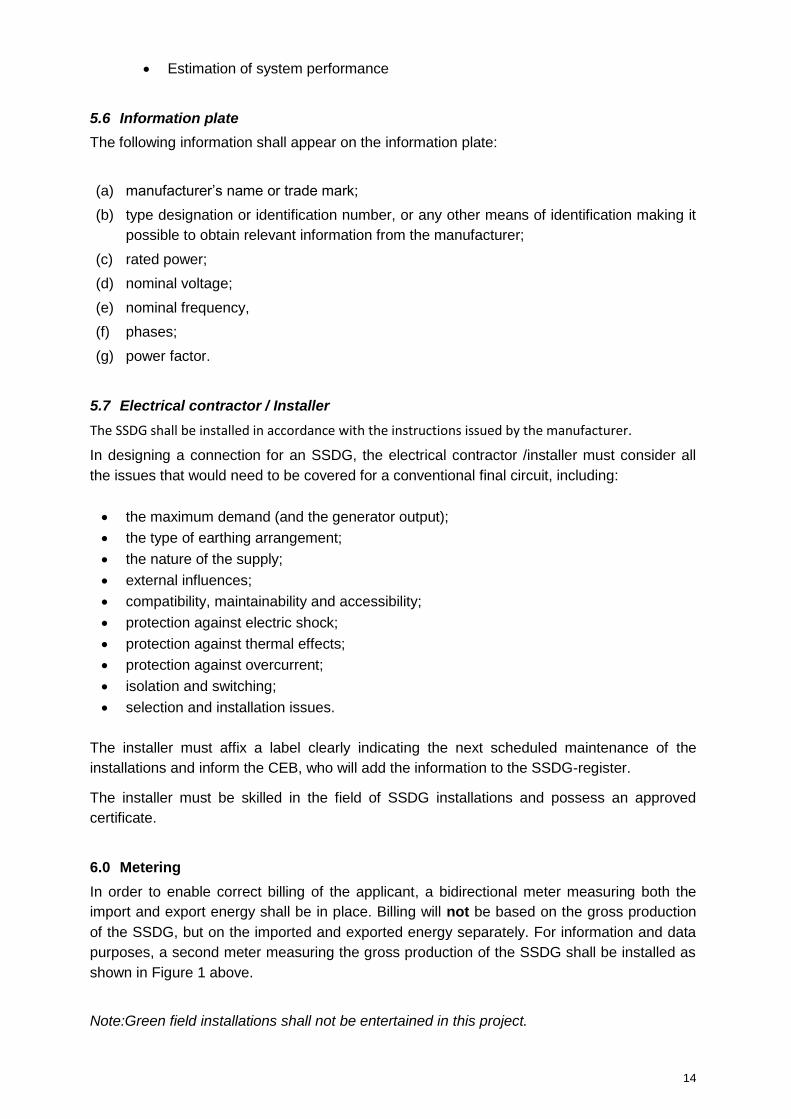
(b) A summary of the protection‟s separate settings incorporated within the equipment. The
figure 3 below is an example of the type of circuit diagram that needs to be displayed.
This diagram is for illustrative purposes and not intended to be fully descriptive.
Figure 3: Example of circuit diagram for a SSDG installation
(c) In addition the maintenance requirements and maintenance services available shall be
documented.
(d) The applicant shall keep a certificate signed by the maintenance contractor containing at
least the following:
A statement confirming that the solar PV system/wind turbine/hydro meets the
requirements of this standard.
Client‟s name and address.
Site address (if different).
Contractors name, address etc.
List of key components installed.
CEB REGISTERED
14
Estimation of system performance
5.6 Information plate
The following information shall appear on the information plate:
(a) manufacturer‟s name or trade mark;
(b) type designation or identification number, or any other means of identification making it
possible to obtain relevant information from the manufacturer;
(c) rated power;
(d) nominal voltage;
(e) nominal frequency,
(f) phases;
(g) power factor.
5.7 Electrical contractor / Installer
The SSDG shall be installed in accordance with the instructions issued by the manufacturer.
In designing a connection for an SSDG, the electrical contractor /installer must consider all
the issues that would need to be covered for a conventional final circuit, including:
the maximum demand (and the generator output);
the type of earthing arrangement;
the nature of the supply;
external influences;
compatibility, maintainability and accessibility;
protection against electric shock;
protection against thermal effects;
protection against overcurrent;
isolation and switching;
selection and installation issues.
The installer must affix a label clearly indicating the next scheduled maintenance of the
installations and inform the CEB, who will add the information to the SSDG-register.
The installer must be skilled in the field of SSDG installations and possess an approved
certificate.
6.0 Metering
In order to enable correct billing of the applicant, a bidirectional meter measuring both the
import and export energy shall be in place. Billing will not be based on the gross production
of the SSDG, but on the imported and exported energy separately. For information and data
purposes, a second meter measuring the gross production of the SSDG shall be installed as
shown in Figure 1 above.
Note:Green field installations shall not be entertained in this project.
15
7.0 Testing, commissioning and maintenance
Testing of SSDGs will be done in the presence of the CEB. The applicant shall notify the CEB
in advance with a testing and commissioning plan. The applicant shall keep written records of
test results and protection settings. The applicant shall regularly maintain their protection
systems in accordance with good electrical industry practice.
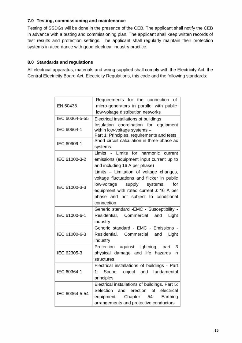
8.0 Standards and regulations
All electrical apparatus, materials and wiring supplied shall comply with the Electricity Act, the
Central Electricity Board Act, Electricity Regulations, this code and the following standards:
EN 50438
Requirements for the connection of
micro-generators in parallel with public
low-voltage distribution networks
IEC 60364-5-55 Electrical installations of buildings
IEC 60664-1 Insulation coordination for equipment within low-voltage systems – Part 1: Principles, requirements and tests
IEC 60909-1 Short circuit calculation in three-phase ac
systems.
IEC 61000-3-2
Limits - Limits for harmonic current
emissions (equipment input current up to
and including 16 A per phase)
IEC 61000-3-3
Limits – Limitation of voltage changes,
voltage fluctuations and flicker in public
low-voltage supply systems, for
equipment with rated current ≤ 16 A per
phase and not subject to conditional
connection
IEC 61000-6-1
Generic standard -EMC - Susceptibility -
Residential, Commercial and Light
industry
IEC 61000-6-3
Generic standard - EMC - Emissions -
Residential, Commercial and Light
industry
IEC 62305-3
Protection against lightning, part 3
physical damage and life hazards in
structures
IEC 60364-1
Electrical installations of buildings - Part
1: Scope, object and fundamental
principles
IEC 60364-5-54
Electrical installations of buildings. Part 5:
Selection and erection of electrical
equipment. Chapter 54: Earthing
arrangements and protective conductors

16
IEEE P1547 Series of Standards for Interconnection,
May, 2003, NREL/CP-560-34003
IEEE519-1992
IEEE Recommended practice and
requirements for harmonic control of
electric power systems, Institute of
Electrical and Electronic Engineers,
Piscataway, NJ. April 1992
IEEE C37.90
IEEE Standard for Relays and Relay
Systems Associated with Electric Power
Apparatus
9.0 Conditions on network for review of application
The total capacity of installed distributed generators (SSDG) on the relevant 22kV/0.4 kV
or 6.6kV/0.4kV transformer exceeds 25 % of the LV transformer fuse capacity.
The total capacity of installed distributed generators (SSDG) on the relevant low voltage
feeder exceeds 90 % of the feeder fuse capacity.
The capacity of SSDG at one consumer terminal exceeds the capacity of the fuse at the
existing consumer terminal.
The capacity of SSDG at one installation exceeds 25 kW in certain areas.

17
“AC” means Alternating Current; “Applicant” means a producer of electricity through a SSDG installation; “CEB” means the Central Electricity CEB; “ Circuit breaker ” means a switching device capable of making, carrying, and breaking currents under normal circuit conditions and also making, carrying for a specified time, and breaking currents under specified abnormal conditions such as those of short circuit; “DC” means Direct Current; “Dedicated transformer” means a transformer installed between the CEB‟s network and SSDG network that serves only the SSDG and attached loads, if any; “DG” means Distributed Generation; “Distributed generation” means electric generation facilities connected to the Utility network at the PCC; “Directional-power relay” means a relay that operates on a predetermined value of power flow in a given direction, or upon reverse power so that, when used with SSDG in a non-export configuration, it will prevent power flow into the CEB´s Network; “Flicker” means a variation of input voltage sufficient in duration to allow visual observation of a change in electric light source intensity; “Fault” means a physical condition that causes a device, a component, or an element to fail to perform in a required manner, for example a short-circuit, a broken wire, an intermittent connection; “Frequency” means the number of complete cycles of sinusoidal variations per unit time; “Greenfield” means an installation of SSDG at a location without existing connection point; “Grid” means CEB‟s network that brings electricity from power stations to consumers” “THD” means Total Harmonic Distortion
“Harmonic distortion” means continuous distortion of the normal sine wave; typically caused by nonlinear loads or by inverters, measured in Total Harmonic Distortion (THD); “IGBT” means Insulated-gate bipolar transistor; “Installer” means a person who has followed a course on Certified SSDG installation and been awarded a certificate from MITD; “IPP” means an Independent Power Producer;
Annex 1: Abbreviations and definitions
18
“Islanding” means a condition in which a portion of the CEB‟s network is energised by one or
more SSDGs through their PCC(s) while electrically separated from the rest of the system;
“Isolated Generation” means a condition where the electrical path at the PCC is open and the
SSDG continues to energise local loads;
“kV” means kilovolt;
“kVA” means Kilovolt Ampere
“kW” means Kilo Watt (1,000 W = 1,000 J/s);
“kWh” means Kilowatt hour (1,000 watt hours);
“LV” means Low Voltage (Voltage below 1,000 V);
„MITD‟ means Mauritius Institute of Training and Development
“MW” means megawatt (1,000,000 W = 1,000,000 J/s);
“Parallel operation” means a condition where the SSDG is operating while connected to
CEB‟s network;
“PCC” means point of common coupling;
“Point of Common Coupling (PCC)” means the point at which a SSDG is connected to the
CEB‟s network;
“Power factor Ratio” means ratio of real to total apparent power (kW/kVA) expressed as a
decimal or percentage;
“Producer” means a producer of electricity through a SSDG installation or the owner thereof;
“PV” means photovoltaic;
“PWM” means Pulse width modulation;
“RE” means renewable energy;
“SSDG” means Small Scale Distributed Generation up to 50 kW as categorised in Schedule 2
“SWC” means Surge Withstand Capability, the immunity of this equipment to fast and
repetitive electrical transients;
“TT system” means in a TT earthing system, the protective earth connection of the consumer
is provided by a local connection to earth;
“Voltage-restrained over-current relay” means a protective relay in which the pickup and
over-current tripping times are affected by the voltage.
19
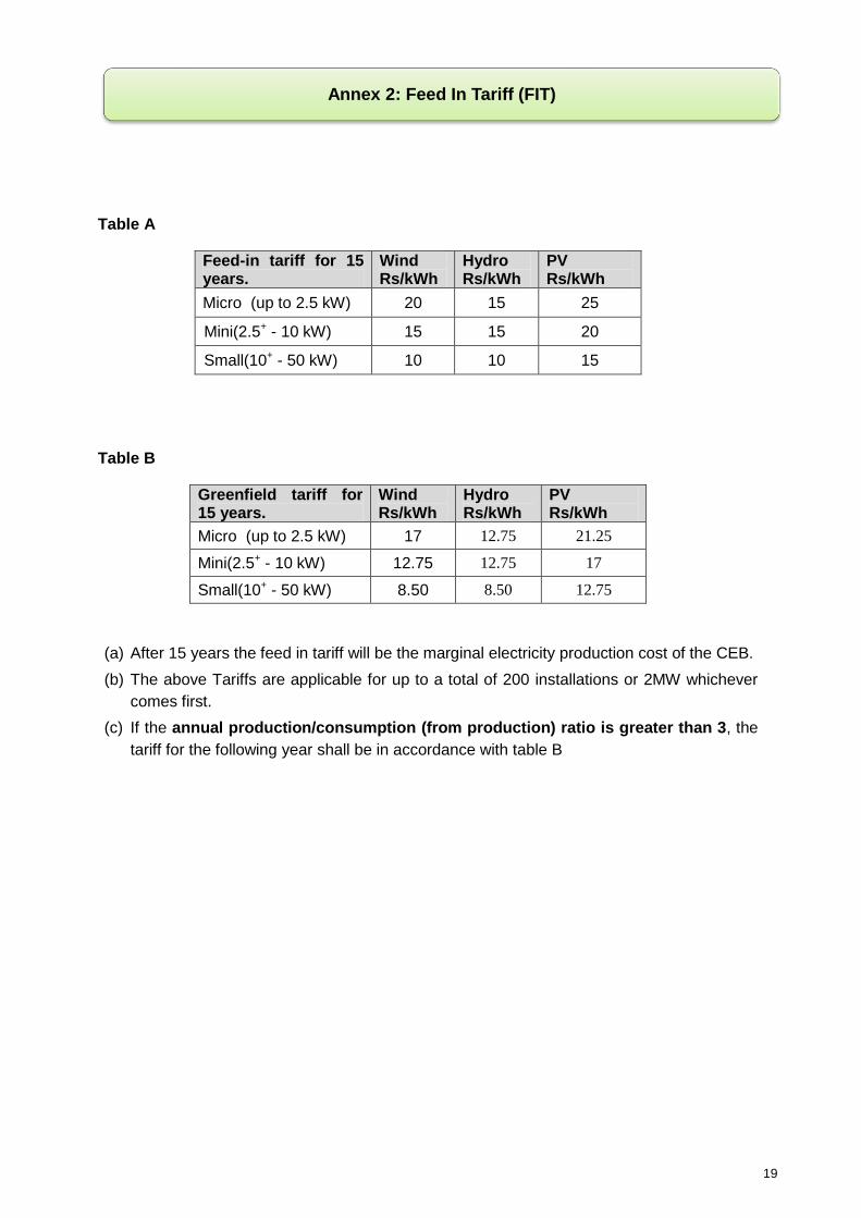
Table A
Feed-in tariff for 15 years.
Wind Rs/kWh
Hydro Rs/kWh
PV Rs/kWh
Micro (up to 2.5 kW) 20 15 25
Mini(2.5+ - 10 kW) 15 15 20
Small(10+ - 50 kW) 10 10 15
Table B
Greenfield tariff for 15 years.
Wind Rs/kWh
Hydro Rs/kWh
PV Rs/kWh
Micro (up to 2.5 kW) 17 12.75 21.25
Mini(2.5+ - 10 kW) 12.75 12.75 17
Small(10+ - 50 kW) 8.50 8.50 12.75
(a) After 15 years the feed in tariff will be the marginal electricity production cost of the CEB.
(b) The above Tariffs are applicable for up to a total of 200 installations or 2MW whichever
comes first.
(c) If the annual production/consumption (from production) ratio is greater than 3, the
tariff for the following year shall be in accordance with table B
Annex 2: Feed In Tariff (FIT)
20
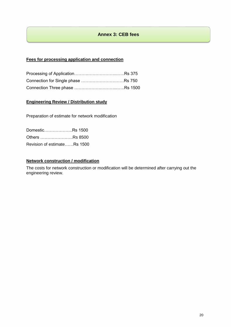
Fees for processing application and connection
Processing of Application……….………………...…..Rs 375
Connection for Single phase …………………………Rs 750
Connection Three phase ……………….………...…..Rs 1500
Engineering Review / Distribution study
Preparation of estimate for network modification
Domestic………………..Rs 1500
Others …………………..Rs 8500
Revision of estimate……Rs 1500
Network construction / modification
The costs for network construction or modification will be determined after carrying out the engineering review.
Annex 3: CEB fees

21
Serial No….………… (For office use only)
SSDG Application Form
Applicant Information For office
use only Name
Postal address
Contact telephone number
Fax number
Tax Account Number
VAT Registration Number (if applicable)
Business Registration Number (if applicable)
Email address
Installer details *1
Installer
Accreditation/qualification
Postal address
Contact person
Telephone number
Fax number
Email Address
Project details For office
use only
Site/project address
Telephone number (project site)
Business Partner Number (please refer to your electricity bill or alternatively
attach a recent electricity bill)
Contract Account Number (please refer to your electricity bill or alternatively
attach a recent electricity bill)
Expected installation commencement date
Expected commissioning date
SSDG details
SSDG location within the installation
Total number of SSDG units to be installed
under this project, to include SSDG unit
location and capacity in KW & kVA
No. of Units: ………..of
………kW each
Total KW : ……………
Total KVA:……………...
Any other known SSDG on installation site
Type of RE technology
(photovoltaic/ hydro/ wind
Expected annual generation (kWh)
Annex 4: SSDG Application Form

22
Declaration – to be completed by applicant
Comments (use separate sheet if necessary)
I declare that this installation has been
designed to comply with the requirements of
the Grid code for SSDG.
Name :
Signature & Date :
Other information to be enclosed For office use only
SSDG type verification test certificate, to include the following information:
Yes/No if submitted
Type of SSDG (RE technology)
Manufacturer and model type
Country of origin
SSDG rating (A), power factor and frequency
Single or multi phase
Maximum peak short circuit current (A)
Standard of compliance**2
Contact details – telephone number, web address etc
Copy of system circuit diagram (single line diagram) within the installation including the proposed grid connection and the associated metering points/ supply points
Earthing arrangements
Site layout plan showing location of SSDGs and other major electrical equipment installed – if applicable
CEB comments – to be completed by CEB representative following application
As a representative of the CEB, I give, in principle, permission for the connection of these SSDG units. If „no‟ see comments below
Yes No
Comments
Name, date and signature
*1 At the start of this project until further notice, the CEB shall accept a „Certificate‟ from the supplier of the
equipment certifying that the installer is well-versed with the installation of the equipment. Furthermore, the topics covered and the duration of the training shall be mentioned on the „Certificate’.
**2 All SSDGs to submit certificate of compliance with the Electrical Equipment Safety Regulations and the
Electromagnetic Compatibility Regulations (CE Marked). PV installations to submit certificates that the panels are to IEC 61215 for crystalline silicon and IEC 61646 for thin film silicon. Wind installations to submit certificates that the wind turbine is as per IEC 61400-2.

23
SSDG Guaranteed Particulars
(All information given hereunder should be substantiated by documents from the Manufacturer)
S.
No. Parameters Requirements Proposed
1 Inverter Type Central Inverter OR
Micro inverter
2 Capacity of Inverter To specify
3 Protection Parameters
Settings
Trip
Setting
Clearance
Time
Trip
Setting
Clearance
Time
Trip
Indication
Provided
4 Over Voltage (a)
(230 V + 10 %) 253 V 0,2 s
5 Over Voltage (230 V + 6 %)
243.8 V 1,5 s
6 Under Voltage (230 V – 6 %)
216.2 V 1,5 s
7 Over Frequency (b)
(50 Hz + 2 %) 51 Hz 0,5 s
8 Under Frequency (50 Hz - 6 %)
47 Hz 0,5 s
9 Loss of Mains (df/dt - Vector shift)
2.5 Hz / s
10 degrees 0,5 s
10 Islanding Detection Yes
11 Isolated Generation possible
Yes / No
12 Reconnection Time 3 mins.
13 Max. DC Current injection to grid
To specify
14 Rated AC output Current per phase
To specify
15 Total Harmonics Distortion (Voltage)
To specify
16 Total Harmonics Distortion (Current)
To specify
17 Surge Withstand Capability
To specify
18 Power Factor (leading & lagging)
0.95
19 Will first Switch after meter have visible contacts ?
Yes
20 Will first Switch after meter have lock facilities in open position ?
Yes
21 Will Production Meter be installed ?
Yes / No
22 Will Earthing System be TT ?
Yes
23 Will Batteries be Installed ?
Yes / No
Note: For No.4 and No.7 see clause 2.4 of Grid Code
Signature of applicant:………………………………
24
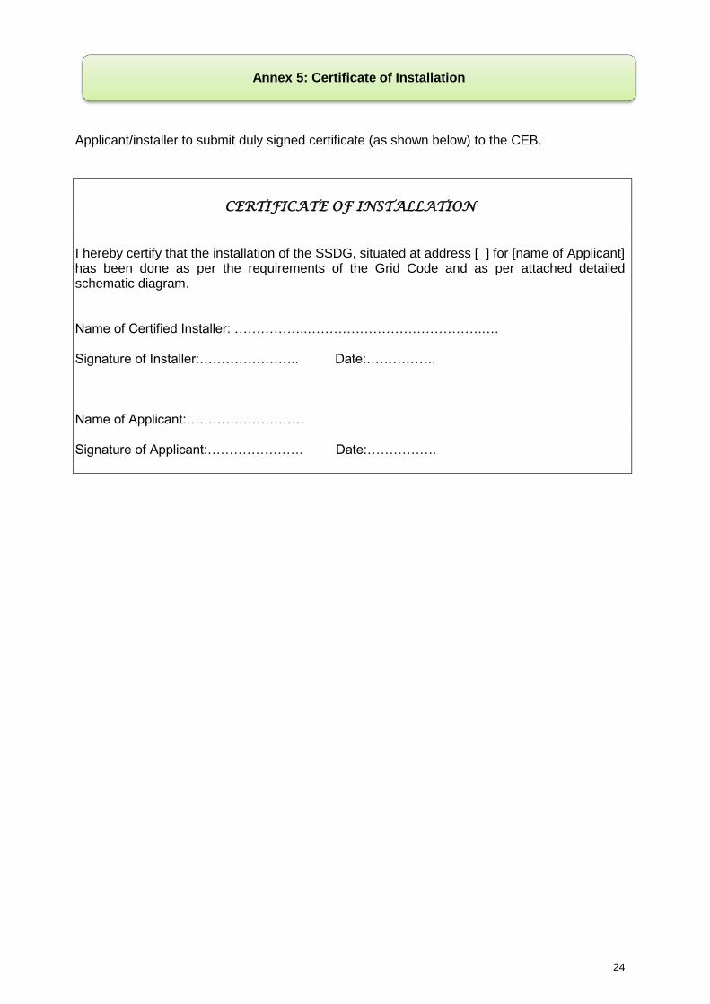
Applicant/installer to submit duly signed certificate (as shown below) to the CEB.
CERTIFICATE OF INSTALLATION
I hereby certify that the installation of the SSDG, situated at address [ ] for [name of Applicant] has been done as per the requirements of the Grid Code and as per attached detailed schematic diagram. Name of Certified Installer: ……………..………………………………….…. Signature of Installer:………………….. Date:……………. Name of Applicant:……………………… Signature of Applicant:…………………. Date:…………….
Annex 5: Certificate of Installation

25
After commissioning of SSDG, CEB will issue commissioning certificate to applicant.
CERTIFICATE OF COMMISSIONING This is to certify that the SSDG installation, situated at [address] in the name of Applicant [name] complies with the requirements of the Grid Code and it has been commissioned on………………… by the Central Electricity Board‟s SSDG Commissioning Team. District Section Name: ……………………………….. Signature: ……………………………. SSDG Unit Name: ……………………………….. Signature: ……………………………. Meter Lab section Name: ……………………………….. Signature: ……………………………. Health and Safety Officer Name: ……………………………….. Signature: …………………………….
Annex 6: Certificate of Commissioning

26
This Connection Agreement is made (date and place):
_____________________.
BETWEEN
________________________, (the CEB)
AND
____________________________, (the “customer”)
(Each a “Party” and collectively the “Parties”)
1. WHEREAS The CEB is the owner of the distribution system.
2. And WHEREAS the Customer owns or operates a small scale distributed generation
facility (the "Facility").
3. And WHEREAS the Customer has connected or wishes to connect its facility to CEB´s
distribution system and CEB has connected or has agreed to connect the facility to the
distribution system.
4. And WHEREAS the CEB has previously reviewed and accepted the Customer's
application to connect and related materials that were submitted to the CEB in accordance
with the process set out in the Grid Code (the "Code") (altogether, the "Application")
5. And WHEREAS in accordance with the Electricity Act and the Grid Code, the CEB has
agreed to offer, and the Customer has agreed to accept, distribution service in relation to
the Facility.
NOW THEREFORE in consideration of the foregoing, and of the mutual covenants,
agreements, terms and conditions herein contained, the Parties, intending to be legally
bound, hereby agree as follows:
Annex 7: Connection Agreement

27
1. Definitions
1.1 Words and phrases contained in this Agreement (whether capitalized or not) that are not
defined in this Agreement have the meanings given to them in the Electricity Act, the
Central Electricity Board Act with subsequent amendments, the Utility Regulatory
Authority Act and The Interpretation and General Clauses Act or the Code.
2. Type of Facility
2.1 The Facility has a name-plate rated capacity below 50 kW and applies as a Small Scale
Distributed Generator.
3. Incorporation of code and Application of Conditions of Service and Other Contracts
3.1 The Code is hereby incorporated in its entirety by reference into, and forms part of, this
Agreement. Unless the context otherwise requires, all references to “this Agreement”
include a reference to the Code.
3.2 The CEB hereby agrees to be bound by and at all times to comply with the Code, and the
Customer acknowledges and agrees that the CEB is bound at all times to comply with the
Code in addition to complying with the provisions of this Agreement.
3.3 In addition to this Agreement, the relationship between the CEB and the Customer will be
governed by the CEB‟s Conditions of Service that are in effect at the relevant time. In the
event of a conflict or an inconsistency between a provision of this Agreement and a
provision of the CEB‟s Conditions of Service, the provision of this Agreement shall
govern.
4. Facility Standards
4.1 The Customer shall ensure that the Facility:
(a) meets all applicable requirements of the Electricity Act; and
(b) is installed, constructed, operated and maintained in accordance with this Agreement, the
CEB‟s offer to connect, and meets the technical and operating requirements described
and approved in the application form.
5 Charges, Settlement and Billing
5.1 The selling price (feed-in tariff) for export of electricity from the facility to the grid is
described below.

28
Tariffs for electricity production
The SSDG is a
………………… Micro (up to 2.5 kW)
………………… Mini (2.5+ to 10 kW)
………………… Small (10+ to 50 kW)
………………… Wind
………………… PV
………………… Hydro
installation.
The selling price for the electricity production is set out below, and is fixed for a period of
exactly XX years; with the commencement date for this XX year period being the date this
agreement comes into effect.
For facilities exporting the net electricity production of the consumer installation to the grid,
the selling price is fixed to xx MUR/kWh.
5.2 If the annual production/consumption (from production) ratio is greater than 3, the tariff for
the following year shall be in accordance with Table B in Annex 2. An addendum to this
agreement shall be signed by both parties.
5.3 An export bill with a detachable SSDG Invoice detailing the amount of energy exported to
the grid will be given to the SSDG owner. SSDG owner has to sign on the Invoice and
forward it back to the SSDG Unit at the CEB Head Office at Curepipe.
5.4 Upon receipt of the signed SSDG Invoice,a cheque will be issued and posted to the
SSDG owner.
5.5 In case the import bill(s) is not settled after notification by CEB, the service line to the
customer will be disconnected from the grid.
6. Representations and Warranties
6.1 The Customer represents and warrants to the CEB as follows, and acknowledges that the
CEB is relying on the following representations and warranties without independent
inquiry in entering into this Agreement:
(a) the Facility is fully and accurately described in the Application;

29
(b) all information in the Application is true and correct;
(c) the Facility is in compliance with all applicable technical requirements and laws;
(d) the Customer has been given warranty information and operation manuals for the Facility;
(e) the Customer has been adequately instructed in the operation and maintenance of the
Facility and the Customer has developed and implemented an operation and
maintenance plan based on those instructions;
(f) the Customer has all necessary power, authority and capacity to enter into this
Agreement and to perform its obligations under this Agreement;
(g) this Agreement constitutes a legal and binding obligation on the Customer, enforceable
against the Customer in accordance with its terms;
(h) the Customer holds all permits, licences and other authorizations that may be necessary
to enable it to own and operate the Facility; and
(i) any individual signing this Agreement on behalf of the Customer has been duly authorized
by the Customer to sign this Agreement and has the full power and authority to bind the
Customer.
6.2 The CEB represents and warrants to the Customer as follows, and acknowledges that the
Customer is relying on the following representations and warranties without independent
inquiry in entering into this Agreement:
(a) the CEB is duly incorporated under the laws of Mauritius;
(b) the CEB has all necessary power, authority and capacity to enter into this Agreement
and to perform its obligations under this Agreement;
(c) this Agreement constitutes a legal and binding obligation on the CEB, enforceable
against the CEB in accordance with its terms; and
(d) any individual signing this Agreement on behalf of the CEB has been duly authorized by
the CEB to sign this Agreement and has the full power and authority to bind the CEB.
7. Connection Disconnect Device
7.1 The Customer shall furnish and install a connection disconnect switch for the Facility that
opens, with a visual break, all ungrounded poles of the connection circuit. The
connection disconnect switch shall be rated for the voltage and fault current
requirements of the Facility, and shall meet all applicable standards. The switch
enclosure, if applicable, shall be properly grounded. The connection disconnect switch
shall be accessible at all times, located for ease of access to the CEB‟s personnel, and
shall be capable of being locked in the open position. The Customer shall follow the
CEB‟s procedures for switching, clearance, tagging, and locking.
8. Modifications to the Facility
30
8.1 The Customer shall not modify (increase capacity) its connection assets or the Facility except in accordance with this section. Where the modification will not increase the maximum electrical output of the Facility, the Customer shall give the CEB no less than 15 working days notice prior to the date on which the modification will be made. Where the modification will increase the maximum electrical output of the Facility, the Customer shall submit a new application for connection to the CEB. The CEB shall process that application for connection in accordance with the Code. The Customer shall not commence such modification until that process has been completed.
9. Indemnity
9.1 The customer shall indemnify the CEB for damages claimed by third parties where the
cause of the loss due to acts and or omission of the customer.
10. Liability and Force Majeure
10.1 A Party shall have a duty to mitigate any losses relating to any claim for indemnification
from the other Party that may be made in relation to that other Party. Nothing in this
section shall require the mitigating Party to mitigate or alleviate the effects of any strike,
lockout, restrictive work practice or other labour dispute.
10.2 A Party shall give prompt notice to the other Party of any claim with respect to which
indemnification is being or may be sought under this Agreement.
10.3 CEB shall not be liable to any damage caused during cyclonic/surge/lightning or other
adverse conditions beyond its control which may prevail during the installation and
operation of the SSDG.
11. Access to Facility
11.1 Each Party shall ensure that its facilities are secured at all times.
11.2 The Customer shall permit and, if the land on which the Facility is located is not owned
by Customer, cause such landowner to permit, the CEB's employees and agents to
enter the property on which the Facility is located at any reasonable time. Such access
shall be provided for the purposes of inspecting and/or testing the Facility as and when
permitted by this Agreement, the Grid Code or the CEB‟s Conditions of Service or as
required to ensure the continued safe and satisfactory operation of the Facility, to
ensure the accuracy of the CEB's meters, to establish work protection, or to perform
work.
11.3 Any inspecting and/or testing referred to in section 11.2 shall not relieve the Customer
from its obligation to operate and maintain the Facility and any related equipment
owned by the Customer in a safe and satisfactory operating condition and in
accordance with this Agreement.
12. Disconnection of Facility to Permit Maintenance and Repairs
12.1 The CEB will provide the Customer with reasonable notice of any planned equipment
outages in the CEB‟s distribution system which will impact the Facility or its connection.
12.2 The CEB will make reasonable efforts to ensure that the outages referred to in section
12.1 will be of minimal duration and cause minimal inconvenience to the Customer.
31
12.3 In connection with any planned equipment outage, either Party may disconnect or
isolate, or require the disconnection or isolation of, its Facility or system (as applicable)
from the other Party‟s Facility or system (as applicable) so that the employees,
contractors or agents of the Party may construct, maintain, repair, replace, remove,
investigate or inspect its own Facility or system (as applicable) in accordance with the
terms of this Agreement and good utility practice.
12.4 Where practical, the Customer shall notify the CEB prior to temporarily isolating or
disconnecting the Facility from the CEB‟s distribution system.
13. Dispute Resolution
13.1 Any dispute between the Customer and the CEB arising under or in relation to this
Agreement shall be referred to arbitration.
13.2 `The Parties shall comply with the procedure set out in the Code de procedure civile for
the purposes of the Arbitration, provided that nothing shall prevent a Party from seeking
urgent or interlocutory relief from a court in relation to any dispute arising under or in
relation to this Agreement.
13.3 ̀ This clause shall survive the termination of the present agreement howsoever caused.
14. Amendments
14.1 The Parties may by mutual agreement amend this Agreement to reflect changes that
may from time to time be made to the Code during the term of this Agreement.
14.2 Any amendment to this Agreement shall be made in writing and duly executed by both
Parties.
15. Term of Agreement and Termination
15.1 This Agreement shall become effective upon execution by the Parties, and shall
continue in effect until terminated in accordance with section 15.2 or 15.3.
15.2 The Customer may, if it is not then in default under this Agreement, terminate this
Agreement at any time by giving the CEB thirty days prior written notice setting out the
termination date.
15.3 The CEB may terminate this Agreement upon any material breach of this Agreement by
the Customer (a "Default"), if the Customer fails to remedy the Default within the
applicable cure period referred to in section 15.4 after receipt of written notice of the
Default from the CEB.
15.4 The Customer shall cure a Default within a reasonable cure period and no longer than
sixty working days.
15.5 Termination of this Agreement for any reason shall not affect:

32
the liabilities of either Party that were incurred or arose under this Agreement prior to
the time of termination; or
that expressly apply in relation to disconnection of the Customer‟s facilities following
termination of this Agreement.
15.6 Subject to clause 13 above, termination of this Agreement for any reason shall be
without prejudice to the right of the terminating Party to pursue all legal and equitable
remedies that may be available to it, including injunctive relief.
15.7 The rights and remedies set out in this Agreement are not intended to be exclusive but
rather are cumulative and are in addition to any other right or remedy otherwise
available to a Party at law or in equity.
15.8 Sections 15.5 to 15.7 shall survive termination of this Agreement.
16. Governing Law
16.1 This Agreement shall be governed by the laws of the Republic of Mauritius
17. Entire Agreement
17.1 Except as expressly provided herein, this Agreement constitutes the entire agreement
between the Parties with respect to the subject-matter hereof and supersedes all prior
oral or written representations and agreements of any kind whatsoever with respect to
the subject-matter hereof.
IN WITNESS WHEREOF, the Parties hereto, intending to be legally bound, have caused this
Agreement to be executed by their duly authorized representatives.
__________________________________
Customer Tax Account Number
__________________________________ __________________
Customer Signature and Date
_________________________________
Name (Print)
_________________________________
Title
__________________________________ _____________________
CEB Signature and Date
_________________________________
Name (Print)
_________________________________
Title