FOR SERVICE TECHNICIAN’S USE ONLY file2 Wiring Diagram Schematic shown with door switch and all...
12
1 FOR SERVICE TECHNICIAN’S USE ONLY NOTE: This sheet contains important Technical Service Data. W10590890B Tech Sheet Do Not Remove Or Destroy Control Assembly Meter Check of Loads and Fuses Fuse Service Check: F1 = Small-triac load fuse Check operation of loads during Service Diagnostics cycle. ■ If any of the triac loads work, F1 fuse is OK. ■ If all triac loads fail to work, F1 fuse could be open. See “Fuse Resistance Check.” Fuse Resistance Check: 1. Unplug dishwasher or disconnect power. 2. Measure resistance of fuse F1. NOTE: The fuse is on the bottom of the Control Board but can be checked from the top side. See “Control Pinout” diagram. ■ If resistance is <3 , fuse is OK. ■ If resistance is >3 , replace control. What To Do If Fuse Open: Inspect and check resistance of all loads on fuse. If any loads are open, shorted, or have evidence of overheating or pinched wires, replace loads and/ or repair wires. DANGER Electrical Shock Hazard Only authorized technicians should perform diagnostic voltage measurements. After performing voltage measurements, disconnect power before servicing. Failure to follow these instructions can result in death or electrical shock. WARNING Electrical Shock Hazard Disconnect power before servicing. Replace all parts and panels before operating. Failure to do so can result in death or electrical shock. Voltage Measurement Safety Information When performing live voltage measurements, you must do the following: ■ Verify the controls are in the off position so that the appliance does not start when energized. ■ Allow enough space to perform the voltage measurements without obstructions. ■ Keep other people a safe distance away from the appliance to prevent potential injury. ■ Always use the proper testing equipment. ■ After voltage measurements, always disconnect power before servicing. SPECIFICATIONS Electrical Supply: Lower Spray Arm Rotation: (Under load) 60 Hz, 120 VAC 25 to 40 rpm Supply Water Flow Rate: Upper Spray Arm Rotation: To fill 2 qt (1.9 L) in 27 seconds, 120 psi maximum, 20 psi minimum. 25 to 35 rpm Supply Water Temperature: REPAIR KITS 120°F (49°C) (Before starting a cycle, run water from sink faucet until hot.) Vinyl Touch-up Kits: Water Charge: 675576 (Blue), 676453 (White), 676455 (Gray) 1.3 gal. (4.8 L) first fill (approximate), 1.1 gal. (4.3 L) other fills Control is mounted console b snaps alo side and and/or sc tabs alon Connector brace locks in connectors NOTE: Reinstall brace and box after service if removed. Pinch to Release Connector Box (Must release connector brace to remove box over power connectors.) Rotate Push to Release Pin 1 Pin 1 Rast Connector Pinout
Transcript of FOR SERVICE TECHNICIAN’S USE ONLY file2 Wiring Diagram Schematic shown with door switch and all...

1
FOR SERVICE TECHNICIAN’S USE ONLYNOTE: This sheet contains important Technical Service Data.
W10590890B Tech Sheet Do Not Remove Or Destroy
Control Assembly
Meter Check of Loads and FusesFuse Service Check:
F1 = Small-triac load fuseCheck operation of loads during Service Diagnostics cycle.■ If any of the triac loads work, F1 fuse is OK.■ If all triac loads fail to work, F1 fuse could be open. See “Fuse Resistance
Check.”
Fuse Resistance Check:1. Unplug dishwasher or disconnect power.
2. Measure resistance of fuse F1.NOTE: The fuse is on the bottom of the Control Board but can be checked from the top side. See “Control Pinout” diagram.
■ If resistance is <3 , fuse is OK.■ If resistance is >3 , replace control.
What To Do If Fuse Open:Inspect and check resistance of all loads on fuse. If any loads are open, shorted, or have evidence of overheating or pinched wires, replace loads and/or repair wires.
DANGER
Electrical Shock Hazard
Only authorized technicians should perform diagnostic voltage measurements.
After performing voltage measurements, disconnect power before servicing.
Failure to follow these instructions can result in death or electrical shock.
WARNING
Electrical Shock Hazard
Disconnect power before servicing.
Replace all parts and panels before operating.
Failure to do so can result in death or electrical shock.
Voltage Measurement Safety InformationWhen performing live voltage measurements, you must do the following:
■ Verify the controls are in the off position so that the appliance does not start when energized.
■ Allow enough space to perform the voltage measurements without obstructions.
■ Keep other people a safe distance away from the appliance to prevent potential injury.
■ Always use the proper testing equipment.
■ After voltage measurements, always disconnect power before servicing.
SPECIFICATIONSElectrical Supply: Lower Spray Arm Rotation:(Under load) 60 Hz, 120 VAC 25 to 40 rpmSupply Water Flow Rate: Upper Spray Arm Rotation:To fill 2 qt (1.9 L) in 27 seconds, 120 psi maximum, 20 psi minimum. 25 to 35 rpmSupply Water Temperature: REPAIR KITS120°F (49°C) (Before starting a cycle, run water from sink faucet until hot.) Vinyl Touch-up Kits:Water Charge: 675576 (Blue), 676453 (White), 676455 (Gray)1.3 gal. (4.8 L) first fill (approximate), 1.1 gal. (4.3 L) other fills
Control ismounted console bsnaps aloside and and/or sctabs alon
Connector brace locks in connectorsNOTE: Reinstall brace and box after service if removed.
Pinch to Release
Connector Box (Must release connector brace to remove box over power connectors.)
RotatePush
to R
elease
Pin 1
Pin 1
Rast Connector Pinout
2
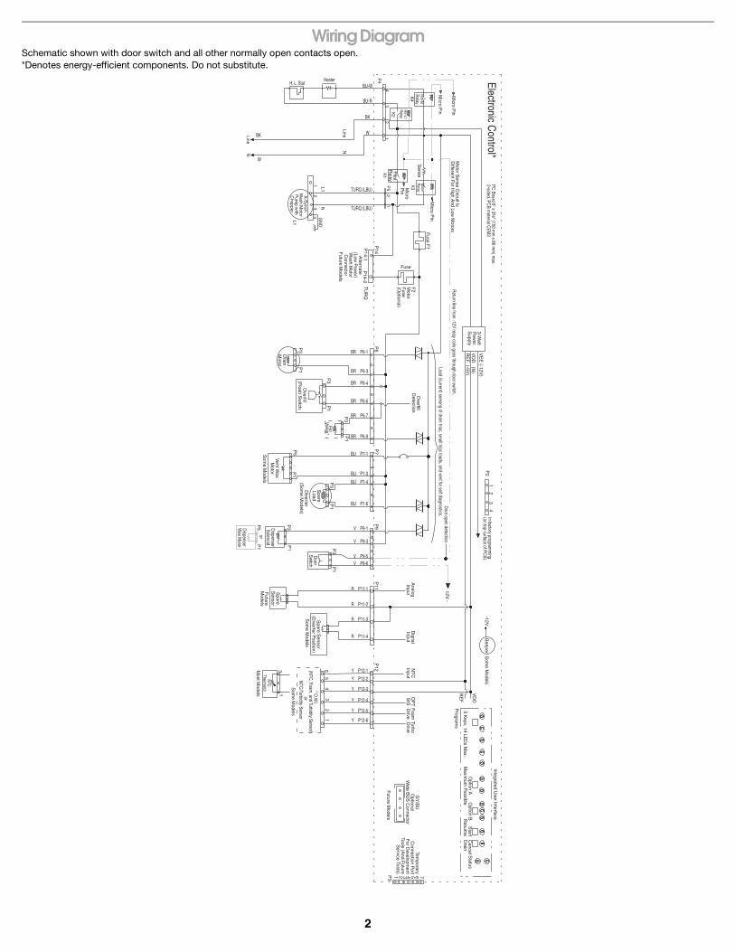
Wiring DiagramSchematic shown with door switch and all other normally open contacts open. *Denotes energy-efficient components. Do not substitute.
Motor S
ense Circuit Is
Different For H
igh And Low
Motors
Micro P
in
Sense
Pilot
Relay
P4
43
21
2P
5
BU-W
BU-R
BK
W
TURQ (LBU)
TURQ (LBU)
HeaterH. L. Stat
BK
W
NNLine
Line
43
21 L1
NG
ND
L1
A-S
ynchW
ash Motor
Pum
p with
Chopper
3-Watt
Pow
erS
upply
VE
E (-12V
)
VD
D (N
)R
EF
(-5V)
Fuse
F2
Motor
Fuse
(Optional)
Overfill
Detection
P6
P7
TU
RQ
P14
P14-1
P14-2
Alternate
(Low P
ower)
Wash M
otorC
onnectorF
uture Models
BR P6-1
BR P6-3
BR P6-4
BR P6-6
BR P6-7
BR P6-9
P1
P1
P3
P3
BU P7-1
P1
P3
Drain
Motor
Overfill
(Float) S
witch
Fill
Valve*
P1
P5
Vent Wax
Motor
Som
e Models
Diverter
(Som
e Models)
P1
P3
P3
P3
P1
P1
Door
Sw
itch
Spare
Load
P9
AnalogInput
P11
BU P7-3
BU P7-4
BU P7-6
V P9-1
V P9-3
V P9-5V P9-6
R P11-1Spare
Sensor
Spare S
ensor(D
iverter Position)
Som
e Models
Som
e Models
Most M
odels
NTC
Thermistor
13
12
43
56
R P11-2
R P11-3
R P11-4
Y P12-1
Y P12-2
Y P12-3
Y P12-4
Y P12-5
Y P12-6
P12
Digital
InputN
TC
InputO
PT
SIG
FoamD
rive
RE
F
VD
D
-12VB
eeperS
ome M
odels
Program
s
12
34
P2
Integrated User Interface
5 Keys, 14 LE
Ds M
ax.M
aximum
Possible
Option A
Option B
Start
Resum
eC
ancelD
rainS
tatus
GY
/BU
Optional
Wide B
US
Connector
Future M
odels
1 2 3 4 5 6 7P3
Temporary
Connection P
ortFor D
evelopment
Tools (And F
utureS
ervice Tools)
1
TurboD
rive
Micro P
in
Fuse F
1
K4
K2
K1
K3
12V -
Future
Models
PC Board 6" x 3
³⁄₈" (150 mm
x 86 mm
) max.
2-sided, PCB m
aterial CEM
3Electronic C
ontrol*
Htr-N
Relay
Htr-L1
Relay
Motor
Relay
Micro P
in
Micro
Pin
Return line from
-12V relay coils goes through door switch.
Load (current) sensing of drain triac, small triac loads, and vent for self diagnostics.
Door open detection
In factory programm
ing(on top surface of PC
B).
Dispenser
Solenoid
P5
P1
Dispenser
Wax M
otor
or
* O.W
.I.(N
TC, Foam, and Turbidity Sensor)
or N
TC/Turbidity Sensor

3
Service Diagnostics Cycle
Service Diagnostics Cycle Notes:
Customer Cycle Operation:To quickly advance through customer cycles, invoke the Rapid Advance mode by pressing HIGH TEMP - HEATED DRY - HIGH TEMP - HEATED DRY, after starting the cycle. Then press START/RESUME to advance through cycle intervals.
NOTE: Rapid Advance mode is automatically enabled in the Service Diagnostic cycle, but must be manually invoked in customer cycles.
18 17 16 15 14 13 12 11 10 9 8 7 6 5 4 3 2 1INTERVALCYCLE, OPTION, AND STATUS LEDsCYCLE 1CYCLE 2CYCLE 3HI TEMPSTART/RESUMECLEANALL OTHER CYCLE, OPTION, AND STATUS LEDs
CY1
STA STA STA STA STA STA STA STA STA STA STA STA STA STA STA STA STA STACLN CLN CLN CLN (CLN) (CLN)ALL
3,5NOTES
INTERVAL TIME (min:sec)TOTAL TIME (MAX.): 20:18
SOIL SENSING INTERVALS AND SENSOR CHECKSTHERMISTOR (temperature sensor)CHECK INTERVAL - Turn Clean LED on ifthermistor is in normal temperature range32˚F to 167˚F (0˚C to 75˚C). NOTE 3
LOADSPILOT RELAYFILLWASH MOTORDISPENSER (DETERGENT/RINSE AID)DRAIN MOTORHEATER
0:06
1:21
1:21
1:21
0:55
0:05
0:40
0:05
Ran
ge b
etw
een
0
:45
- 1:0
0
2:00
3:00
1:00
1:21
1:21
THR
PLTPLT PLT PLT PLT PLT PLT PLT PLTFILFIL FIL
WSHWSHWSHWSH WSHDSP
DRNHTR HTR
2
CU
STO
MER
ER
ROR
1
CU
STO
MER
ER
ROR
2
CU
STO
MER
ER
ROR
3
CU
STO
MER
ER
ROR
4
SERV
ICE
ERRO
R 1
SERV
ICE
ERRO
R 2
STANDBY
41 1 1 10:
10
CY1 CY1 CY1 CY1 CY1 CY1 CY1CY2CY2 CY2 CY2 CY2 CY2 CY2 CY2 CY2 CY2 CY2
CY3CY3 CY3 CY3 CY3 CY3 CY3 CY3HIT HITHIT HIT HIT HIT HIT HIT HIT HIT HIT
CLN CLN CLN
1:21
PLT
DRN
43 5 3 1 1
1:00
3:00
1 To invoke the Diagnostics Cycle, perform the following while in standby:■ Press any 3 keys in the sequence 1-2-3-1-2-3-1-2-3 with no more
than 1 second between keys.■ The Service Diagnostics Cycle will start when the door is closed.■ To rapid advance 1 interval at a time, press the Start/Resume key.
Rapid advance may skip sensor checks as some checks require 2 complete intervals.
NOTE: While in the Diagnostic Cycle, the Start/Resume feature is turned off (for example, Auto Resume after door interrupts) and the Start/Resume key becomes an individual advance key.■ Invoking Service Diagnostics clears all status and last ran
information from memory and restores defaults.■ Drain and wash motors will pulsate on and off.
■ Last ran cycles and options returned to default.■ Last ran delay returns to the lowest delay increment.■ Operating state returns to Standby upon completing or
terminating the Service Diagnostics Cycle.
2 Turn on all LEDs immediately upon receiving entry sequence (even if door is open) for 5 seconds as a display test. Turn off all LEDs for 1 second prior to reporting customer error history.
3 Thermistor (temperature sensor) checks:■ Turn Clean LED on if thermistor is in its normal temperature range
of 32°F to 167°F (0°C to 75°C).
4 Cycle 2 and Hi Temp LEDs flash in this interval. Press Cycle Select key in this interval to clear customer error history.
5 Turn on Clean LED in this interval if dispenser current detected in previous interval.
4
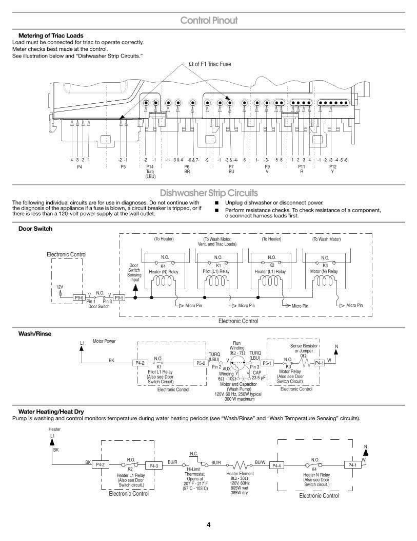
Control PinoutMetering of Triac Loads
Load must be connected for triac to operate correctly.Meter checks best made at the control.See illustration below and “Dishwasher Strip Circuits.”
Dishwasher Strip CircuitsThe following individual circuits are for use in diagnoses. Do not continue with the diagnosis of the appliance if a fuse is blown, a circuit breaker is tripped, or if there is less than a 120-volt power supply at the wall outlet.
■ Unplug dishwasher or disconnect power.■ Perform resistance checks. To check resistance of a component,
disconnect harness leads first.
Door Switch
Wash/Rinse
Water Heating/Heat DryPump is washing and control monitors temperature during water heating periods (see “Wash/Rinse” and “Wash Temperature Sensing” circuits).
Ω of F1 Triac Fuse
P4
-4 -3 -2 -1 -2 -1 -2 -1 -1- -3 & 4- -6 & 7- -9 -1 -3 & -4- -6 1- -3- -5 -6 -1 -2 -3 -4 -1 -2 -3 -4 -5 -6P12 Y
P11 R
P9 V
P7BU
P6BR
P14 Turq (LBU)
P5
12V
Electronic Control
P9-6 V VN.O.
Pin 1 Pin 3Door Switch
P9-5
Door SwitchSensing Input
(To Heater)
N.O. N.O. N.O. N.O.
(To Wash Motor, Vent, and Triac Loads)
(To Heater) (To Wash Motor)
Heater (N) RelayK4
Electronic Control
K1 K2 K3Pilot (L1) Relay Heater (L1) Relay Motor (N) Relay
Micro Pin Micro Pin Micro Pin Micro Pin
Motor Power
BK N.O.TURQ(LBU)
K1 Pilot L1 Relay(Also see Door Switch Circuit)
Electronic Control
P4-2 P5-2Pin 3 Pin 2 K3
Motor Relay(Also see Door Switch Circuit)
WP5-1 P4-1
Sense Resistor or Jumper 0Ω
NL1
V
Y Y AUX Winding6Ω - 10Ω
CAP23.5 µF
RunWinding3Ω - 7Ω
Motor and Capacitor (Wash Pump)120V, 60 Hz, 250W typical 300 W maximum
TURQ(LBU)
Electronic Control
N.O.
L1
BK
BK N.O.
K2Heater L1 Relay (Also see Door Switch circuit.)
Electronic Control Electronic Control
P4-2 P4-3BU/R
N.C.
Hi-Limit Thermostat Opens at 207˚F - 217˚F(97˚C - 103˚C)
BU/R BU/WP4-4
Heater Element 8Ω - 30Ω 120V, 60Hz 805W wet 385W dry
N.O.P4-1
W
N
K4Heater N Relay(Also see Door Switch circuit.)
Heater

5
WATER TEMPERATURE SENSING
Fill
Drain
Dispenser (Detergent and Rinse Aid)
Vent
5V P12-3
P11-3
Pin 1(O.W.I. Pin 4)
Pin 3(O.W.I. Pin 6)
Y Y
Electronic Control Electronic Control
T
NTC Thermistor (and/or O.W.I.) 48,000Ω - 52,000Ω at 77˚F (25˚C)12,000Ω - 13,000Ω at 140˚F (60˚C)
Test hole for P12-3 may crowd P12-1.Recommend using test hole P11-3.
NTC Input
L1
BK P4-2
Use P5-2 as testpoint for fuse F1.
N.O.
K1 Pilot L1 Relay(Also see Door Switch circuit.)
Fuse F1
Electronic Control Electronic ControlTest hole for P6-3 and P6-4 may crowd P6-6 and P6-7. Recommend using test hole for P7-3.
P5-2
P6-4
P7-3
BR BR BR BR
Float (In normal positionholds switch closed.)
N.O.
Pin 3 Pin 1
OverfillFloat Switch
P6-6 P6-7
Float Switch Input
Pin 3 Pin 1P6-9 P4-1 W
N
Fill Valve890Ω - 1,090Ω120V, 60Hz, 6W
Triac
Electronic Control
L1
BKP4-2
N.O.
Pilot L1 Relay(Also see DoorSwitch circuit.) Fuse
F1
Electronic ControlElectronic Control
Use P5-2 as testpoint for fuse F1.
Test hole for P6-3 and P6-4 may crowd P6-1. Recommend using test hole for P7-3.
P5-2
P6-3
P7-3
BR BRPin 1 Pin 3
Drain Motor 15Ω - 19Ω 120V, 60Hz, 100W
P6-1 P4-1
Triac
W
N
L1
BKP4-2
P5-2
P9-3
P7-3
P9-1 P4-1N.O.
K1V V W
N
Fuse F1
Use P5-2 as testpoint for fuse F1.
Pilot L1 Relay(Also see DoorSwitch circuit.)
Test hole for P9-3 may crowd P9-1.Recommend using test hole for P7-3.
Dispenser Wax Motor 1,400Ω - 2,800Ω 120V, 60Hz, 10W
Dispenser Solenoid 280Ω - 340Ω 120V, 60Hz, 11W
Pin 1 Pin 3
Electronic ControlElectronic Control
Triac
L1 Use P5-2 as testpoint for fuse F1.
BK P4-2N.O.
K1 Pilot L1 Relay(Also see Door Switch circuit.)
Fuse F1
Electronic ControlElectronic Control
Test hole for P7-3 may crowd P7-1.Recommend using test hole for P9-3.
P5-2
P7-3
P9-3
Red stripe on plug.
BR
Pin 1 Pin 5
Red stripe on plug.BR P7-1
Vent Wax Motor600Ω - 1,800Ω120V, 60Hz, 6W
P4-1 W
N
6
This Page Intentionally Left Blank
7
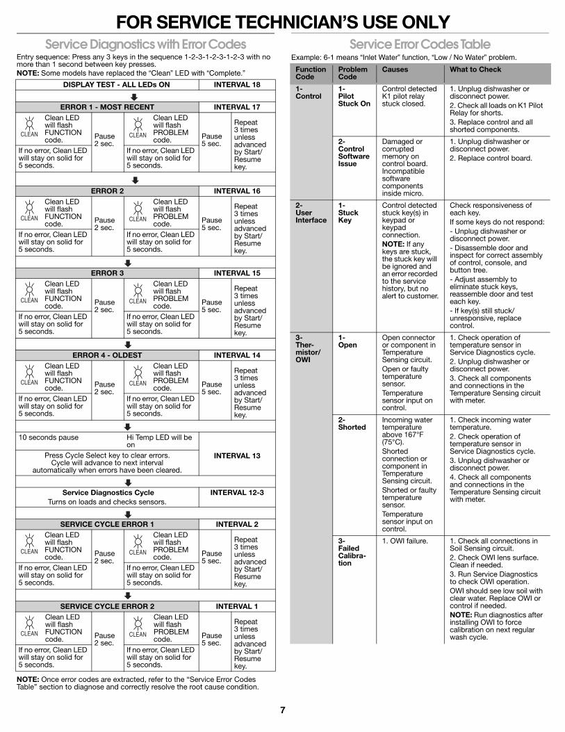
FOR SERVICE TECHNICIAN’S USE ONLYService Diagnostics with Error Codes
Entry sequence: Press any 3 keys in the sequence 1-2-3-1-2-3-1-2-3 with no more than 1 second between key presses.NOTE: Some models have replaced the “Clean” LED with “Complete.”
NOTE: Once error codes are extracted, refer to the “Service Error Codes Table” section to diagnose and correctly resolve the root cause condition.
Service Error Codes TableExample: 6-1 means “Inlet Water” function, “Low / No Water” problem.
DISPLAY TEST - ALL LEDs ON INTERVAL 18
ERROR 1 - MOST RECENT INTERVAL 17Clean LED will flash FUNCTION code. Pause
2 sec.
Clean LED will flash PROBLEM code. Pause
5 sec.
Repeat 3 times unless advanced by Start/Resume key.
If no error, Clean LED will stay on solid for 5 seconds.
If no error, Clean LED will stay on solid for 5 seconds.
ERROR 2 INTERVAL 16Clean LED will flash FUNCTION code. Pause
2 sec.
Clean LED will flash PROBLEM code. Pause
5 sec.
Repeat 3 times unless advanced by Start/Resume key.
If no error, Clean LED will stay on solid for 5 seconds.
If no error, Clean LED will stay on solid for 5 seconds.
ERROR 3 INTERVAL 15Clean LED will flash FUNCTION code. Pause
2 sec.
Clean LED will flash PROBLEM code. Pause
5 sec.
Repeat 3 times unless advanced by Start/Resume key.
If no error, Clean LED will stay on solid for 5 seconds.
If no error, Clean LED will stay on solid for 5 seconds.
ERROR 4 - OLDEST INTERVAL 14Clean LED will flash FUNCTION code. Pause
2 sec.
Clean LED will flash PROBLEM code. Pause
5 sec.
Repeat 3 times unless advanced by Start/Resume key.
If no error, Clean LED will stay on solid for 5 seconds.
If no error, Clean LED will stay on solid for 5 seconds.
10 seconds pause Hi Temp LED will be on
INTERVAL 13Press Cycle Select key to clear errors. Cycle will advance to next interval
automatically when errors have been cleared.
Service Diagnostics CycleTurns on loads and checks sensors.
INTERVAL 12-3
SERVICE CYCLE ERROR 1 INTERVAL 2Clean LED will flash FUNCTION code. Pause
2 sec.
Clean LED will flash PROBLEM code. Pause
5 sec.
Repeat 3 times unless advanced by Start/Resume key.
If no error, Clean LED will stay on solid for 5 seconds.
If no error, Clean LED will stay on solid for 5 seconds.
SERVICE CYCLE ERROR 2 INTERVAL 1Clean LED will flash FUNCTION code. Pause
2 sec.
Clean LED will flash PROBLEM code. Pause
5 sec.
Repeat 3 times unless advanced by Start/Resume key.
If no error, Clean LED will stay on solid for 5 seconds.
If no error, Clean LED will stay on solid for 5 seconds.
CLEAN CLEAN
CLEAN CLEAN
CLEAN CLEAN
CLEAN CLEAN
CLEAN CLEAN
CLEAN CLEAN
Function Code
Problem Code
Causes What to Check
1-Control
1-Pilot Stuck On
Control detected K1 pilot relay stuck closed.
1. Unplug dishwasher or disconnect power.2. Check all loads on K1 Pilot Relay for shorts.3. Replace control and all shorted components.
2-Control Software Issue
Damaged or corrupted memory on control board. Incompatible software components inside micro.
1. Unplug dishwasher or disconnect power.2. Replace control board.
2-User Interface
1-Stuck Key
Control detected stuck key(s) in keypad or keypad connection.NOTE: If any keys are stuck, the stuck key will be ignored and an error recorded to the service history, but no alert to customer.
Check responsiveness of each key.If some keys do not respond:- Unplug dishwasher or disconnect power.- Disassemble door and inspect for correct assembly of control, console, and button tree.- Adjust assembly to eliminate stuck keys, reassemble door and test each key.- If key(s) still stuck/unresponsive, replace control.
3-Ther-mistor/OWI
1-Open
Open connector or component in Temperature Sensing circuit.Open or faulty temperature sensor.Temperature sensor input on control.
1. Check operation of temperature sensor in Service Diagnostics cycle.2. Unplug dishwasher or disconnect power.3. Check all components and connections in the Temperature Sensing circuit with meter.
2-Shorted
Incoming water temperature above 167°F (75°C).Shorted connection or component in Temperature Sensing circuit.Shorted or faulty temperature sensor.Temperature sensor input on control.
1. Check incoming water temperature.2. Check operation of temperature sensor in Service Diagnostics cycle.3. Unplug dishwasher or disconnect power.4. Check all components and connections in the Temperature Sensing circuit with meter.
3-Failed Calibra-tion
1. OWI failure. 1. Check all connections in Soil Sensing circuit.2. Check OWI lens surface. Clean if needed.3. Run Service Diagnostics to check OWI operation.OWI should see low soil with clear water. Replace OWI or control if needed.NOTE: Run diagnostics after installing OWI to force calibration on next regular wash cycle.
8
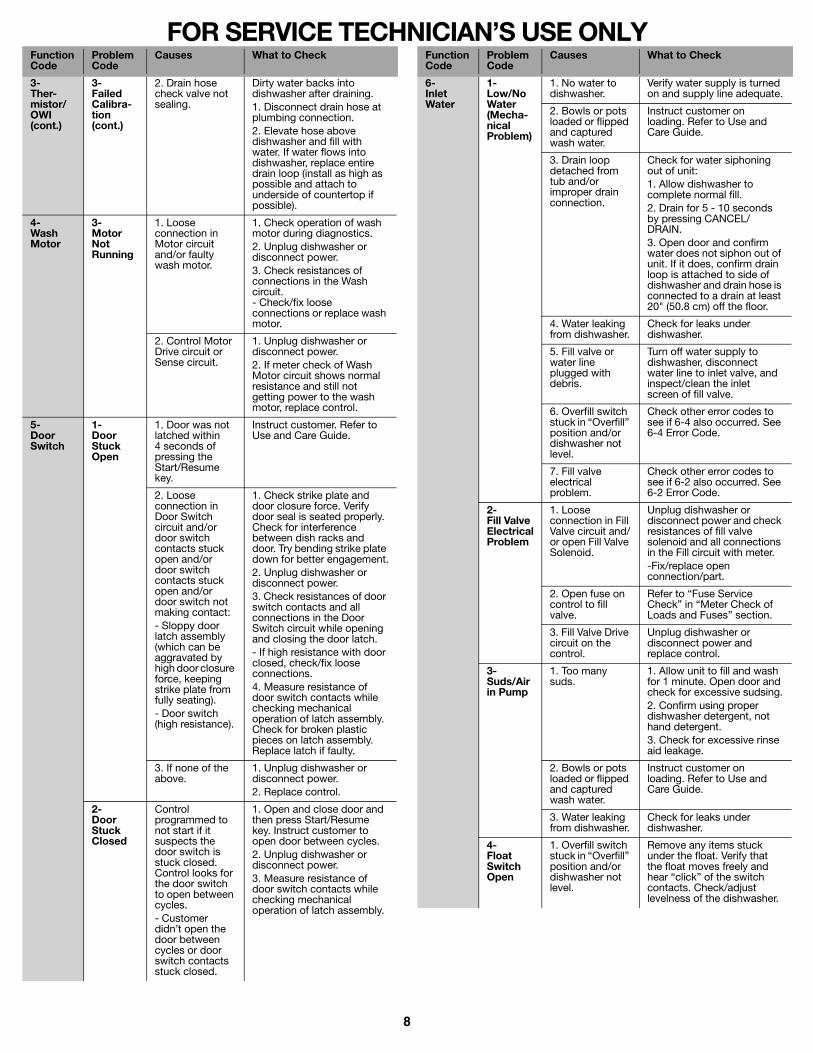
FOR SERVICE TECHNICIAN’S USE ONLY
3-Ther-mistor/OWI (cont.)
3-Failed Calibra-tion (cont.)
2. Drain hose check valve not sealing.
Dirty water backs into dishwasher after draining.1. Disconnect drain hose at plumbing connection.2. Elevate hose above dishwasher and fill with water. If water flows into dishwasher, replace entire drain loop (install as high as possible and attach to underside of countertop if possible).
4-Wash Motor
3- Motor Not Running
1. Loose connection in Motor circuit and/or faulty wash motor.
1. Check operation of wash motor during diagnostics.2. Unplug dishwasher or disconnect power.3. Check resistances of connections in the Wash circuit.- Check/fix loose connections or replace wash motor.
2. Control Motor Drive circuit or Sense circuit.
1. Unplug dishwasher or disconnect power.2. If meter check of Wash Motor circuit shows normal resistance and still not getting power to the wash motor, replace control.
5-Door Switch
1-Door Stuck Open
1. Door was not latched within 4 seconds of pressing the Start/Resume key.
Instruct customer. Refer to Use and Care Guide.
2. Loose connection in Door Switch circuit and/or door switch contacts stuck open and/or door switch contacts stuck open and/or door switch not making contact:- Sloppy door latch assembly (which can be aggravated by high door closure force, keeping strike plate from fully seating).- Door switch (high resistance).
1. Check strike plate and door closure force. Verify door seal is seated properly. Check for interference between dish racks and door. Try bending strike plate down for better engagement.2. Unplug dishwasher or disconnect power.3. Check resistances of door switch contacts and all connections in the Door Switch circuit while opening and closing the door latch.- If high resistance with door closed, check/fix loose connections.4. Measure resistance of door switch contacts while checking mechanical operation of latch assembly. Check for broken plastic pieces on latch assembly. Replace latch if faulty.
3. If none of the above.
1. Unplug dishwasher or disconnect power.2. Replace control.
2-Door Stuck Closed
Control programmed to not start if it suspects the door switch is stuck closed. Control looks for the door switch to open between cycles.- Customer didn’t open the door between cycles or door switch contacts stuck closed.
1. Open and close door and then press Start/Resume key. Instruct customer to open door between cycles.2. Unplug dishwasher or disconnect power.3. Measure resistance of door switch contacts while checking mechanical operation of latch assembly.
Function Code
Problem Code
Causes What to Check
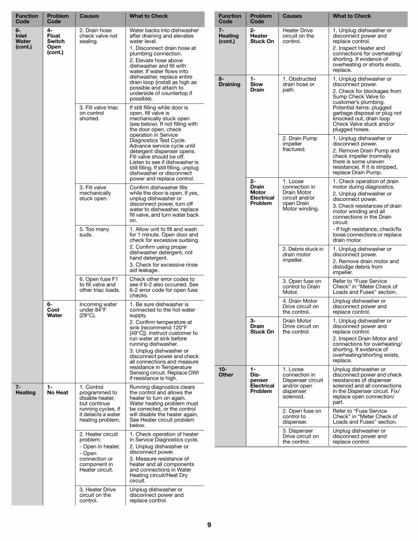
6-Inlet Water
1-Low/No Water (Mecha-nical Problem)
1. No water to dishwasher.
Verify water supply is turned on and supply line adequate.
2. Bowls or pots loaded or flipped and captured wash water.
Instruct customer on loading. Refer to Use and Care Guide.
3. Drain loop detached from tub and/or improper drain connection.
Check for water siphoning out of unit:1. Allow dishwasher to complete normal fill.2. Drain for 5 - 10 seconds by pressing CANCEL/DRAIN.3. Open door and confirm water does not siphon out of unit. If it does, confirm drain loop is attached to side of dishwasher and drain hose is connected to a drain at least 20" (50.8 cm) off the floor.
4. Water leaking from dishwasher.
Check for leaks under dishwasher.
5. Fill valve or water line plugged with debris.
Turn off water supply to dishwasher, disconnect water line to inlet valve, and inspect/clean the inlet screen of fill valve.
6. Overfill switch stuck in “Overfill” position and/or dishwasher not level.
Check other error codes to see if 6-4 also occurred. See 6-4 Error Code.
7. Fill valve electrical problem.
Check other error codes to see if 6-2 also occurred. See 6-2 Error Code.
2-Fill Valve Electrical Problem
1. Loose connection in Fill Valve circuit and/or open Fill Valve Solenoid.
Unplug dishwasher or disconnect power and check resistances of fill valve solenoid and all connections in the Fill circuit with meter. -Fix/replace open connection/part.
2. Open fuse on control to fill valve.
Refer to “Fuse Service Check” in “Meter Check of Loads and Fuses” section.
3. Fill Valve Drive circuit on the control.
Unplug dishwasher or disconnect power and replace control.
3-Suds/Air in Pump
1. Too many suds.
1. Allow unit to fill and wash for 1 minute. Open door and check for excessive sudsing.2. Confirm using proper dishwasher detergent, not hand detergent.3. Check for excessive rinse aid leakage.
2. Bowls or pots loaded or flipped and captured wash water.
Instruct customer on loading. Refer to Use and Care Guide.
3. Water leaking from dishwasher.
Check for leaks under dishwasher.
4-Float Switch Open
1. Overfill switch stuck in “Overfill” position and/or dishwasher not level.
Remove any items stuck under the float. Verify that the float moves freely and hear “click” of the switch contacts. Check/adjust levelness of the dishwasher.
Function Code
Problem Code
Causes What to Check
9
6-Inlet Water (cont.)
4-Float Switch Open (cont.)
2. Drain hose check valve not sealing.
Water backs into dishwasher after draining and elevates water level.1. Disconnect drain hose at plumbing connection.2. Elevate hose above dishwasher and fill with water. If water flows into dishwasher, replace entire drain loop (install as high as possible and attach to underside of countertop if possible).
3. Fill valve triac on control shorted.
If still filling while door is open, fill valve is mechanically stuck open (see below). If not filling with the door open, check operation in Service Diagnostics Test Cycle. Advance service cycle until detergent dispenser opens. Fill valve should be off. Listen to see if dishwasher is still filling. If still filling, unplug dishwasher or disconnect power and replace control.
3. Fill valve mechanically stuck open.
Confirm dishwasher fills while the door is open. If yes, unplug dishwasher or disconnect power, turn off water to dishwasher, replace fill valve, and turn water back on.
5. Too many suds.
1. Allow unit to fill and wash for 1 minute. Open door and check for excessive sudsing.2. Confirm using proper dishwasher detergent, not hand detergent.3. Check for excessive rinse aid leakage.
6. Open fuse F1 to fill valve and other triac loads.
Check other error codes to see if 6-2 also occurred. See 6-2 error code for open fuse checks.
6-Cool Water
Incoming water under 84°F (29°C).
1. Be sure dishwasher is connected to the hot water supply.2. Confirm temperature at sink (recommend 120°F [49°C]). Instruct customer to run water at sink before running dishwasher.3. Unplug dishwasher or disconnect power and check all connections and measure resistance in Temperature Sensing circuit. Replace OWI if resistance is high.
7-Heating
1-No Heat
1. Control programmed to disable heater, but continue running cycles, if it detects a water heating problem.
Running diagnostics clears the control and allows the heater to turn on again. Water heating problem must be corrected, or the control will disable the heater again. See Heater circuit problem below.
2. Heater circuit problem:- Open in heater.- Open connection or component in Heater circuit.
1. Check operation of heater in Service Diagnostics cycle.2. Unplug dishwasher or disconnect power.3. Measure resistance of heater and all components and connections in Water Heating circuit/Heat Dry circuit.
3. Heater Drive circuit on the control.
Unplug dishwasher or disconnect power and replace control.
Function Code
Problem Code
Causes What to Check
7-Heating (cont.)
2-Heater Stuck On
Heater Drive circuit on the control.
1. Unplug dishwasher or disconnect power and replace control.2. Inspect Heater and connections for overheating/shorting. If evidence of overheating or shorts exists, replace.
8-Draining
1-Slow Drain
1. Obstructed drain hose or path.
1. Unplug dishwasher or disconnect power.2. Check for blockages from Sump Check Valve to customer’s plumbing. Potential items: plugged garbage disposal or plug not knocked out, drain loop Check Valve stuck and/or plugged hoses.
2. Drain Pump impeller fractured.
1. Unplug dishwasher or disconnect power.2. Remove Drain Pump and check impeller (normally there is some uneven resistance). If it is stripped, replace Drain Pump.
2-Drain Motor Electrical Problem
1. Loose connection in Drain Motor circuit and/or open Drain Motor winding.
1. Check operation of drain motor during diagnostics.2. Unplug dishwasher or disconnect power.3. Check resistances of drain motor winding and all connections in the Drain circuit.- If high resistance, check/fix loose connections or replace drain motor.
2. Debris stuck in drain motor impeller.
1. Unplug dishwasher or disconnect power. 2. Remove drain motor and dislodge debris from impeller.
3. Open fuse on control to Drain Motor.
Refer to “Fuse Service Check” in “Meter Check of Loads and Fuses” section.
4. Drain Motor Drive circuit on the control.
Unplug dishwasher or disconnect power and replace control.
3-Drain Stuck On
Drain Motor Drive circuit on the control.
1. Unplug dishwasher or disconnect power and replace control.2. Inspect Drain Motor and connections for overheating/shorting. If evidence of overheating/shorting exists, replace.
10-Other
1-Dis-penser Electrical Problem
1. Loose connection in Dispenser circuit and/or open dispenser solenoid.
Unplug dishwasher or disconnect power and check resistances of dispenser solenoid and all connections in the Dispenser circuit. Fix/replace open connection/part.
2. Open fuse on control to dispenser.
Refer to “Fuse Service Check” in “Meter Check of Loads and Fuses” section.
3. Dispenser Drive circuit on the control.
Unplug dishwasher or disconnect power and replace control.
Function Code
Problem Code
Causes What to Check
10
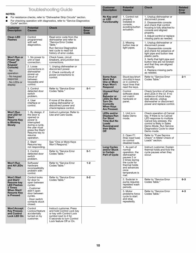
Troubleshooting GuideNOTES:■ For resistance checks, refer to “Dishwasher Strip Circuits” section.■ For checking operation with diagnostics, refer to “Service Diagnostics
Cycle” section.
Customer Description
Potential Causes
Check RelatedError Code
Clean LED Flashes
Control programmed with self diagnostics.
Read error code from the dishwasher and refer to “Service Error Codes Table.”Run Service Diagnostics test cycle to read full history of error codes.
Won’t Run or Power Up (“Dead” Keypad/ Console)- No operation- No keypad response- No LEDs or display
1. No power to unit or bad connection.
Check fuses, circuit breakers, and junction box connections.
2. Loose connections in dishwasher power-up circuit or between keypad(s) and control.
1. Unplug dishwasher or disconnect power.2. Check continuity of power connections to control.
3. Control detected door switch problem.
Refer to “Service Error Codes Table.”
5-1
4. User interface or control.
If none of the above, unplug dishwasher or disconnect power and check/replace control.
Won’t Run and LED for Start/ Resume Key is Blinking Slowly
1. By design, if the door is opened or power is interrupted during a cycle, the user must press the Start/Resume key to resume operation.
Instruct customer. Refer to Use and Care Guide.
2. Start/Resume key not responding.
See “One or More Keys Won’t Respond.”
3. Control detected door switch problem.
Refer to “Service Error Codes Table.”
5-1
Won’t Run and All LEDs On
Software/hardware incompatibility problem with control.
Refer to “Service Error Codes Table.”
1-2
Won’t Start and Start/Resume key LED Flashes 3 Times When Start/Resume Key is Pressed
Control looks for door to open between cycles:- Customer didn’t open door between cycles.- Door switch contacts stuck closed.
Refer to “Service Error Codes Table.”
5-2
Won’t Accept Key Presses and Control Lock LED On
Control Lockout feature accidentally turned on by customer.
Instruct customer. Press and hold Control Lock key or key with Control Lock symbol next to it for 5 seconds to turn Control Lock feature Off or On.
No Key and/or LED Functionality
1. Control not properly installed in console, avoiding button actuation.
1. Unplug dishwasher or disconnect power.2. Disassemble console and check that control housing is fully attached to console and aligned properly.3. Adjust control or replace missing parts as needed.
2. Missing button tree or light pipes.
1. Unplug dishwasher or disconnect power.2. Disassemble console and check for presence of light pipe and button tree plastic parts.3. Verify that light pipe and button tree are not broken and that they are aligned correctly.4. Replace missing parts as needed.
Some Keys Work But One or More Keys Won't Respond
Stuck key/short circuit(s) in keys or in control's input lines that read the keys.
Refer to “Service Error Codes Table.”
2-1
Unusual Key/LED Behavior or LEDs Do Not Turn On Correctly When Keys Are Pressed.
Control software does not match hardware or panel.
Check function of all keys and LEDs in the UI. If no evidence of stuck keys (see above), unplug dishwasher or disconnect power and replace control.
LEDs and/or Displays Run For Short Time (but No Loads Running) and then Shuts Off
1. Unit is in Sales Demo mode.
Check operation of Cancel key. If there is no Cancel LED response to multiple Cancel key presses, the control is likely in Sales Demo Mode. Run Service Diagnostics Cycle to clear Demo mode.
2. Open F1 (triac load fuse) on control disabled loads.
Refer to “Fuse Service Check” in Meter Check of Loads” section.
Long Cycles and/or Stuck in Certain Part of Cycle
1. As part of normal operation, the dishwasher pauses 2 or 3 times during the cycle for thermal holds and advances once temperature is met.
Instruct customer. Explain thermal holds and how the cycle pauses when they occur.
2. Suds/air in pump requires repeated wash periods.
Refer to “Service Error Codes Table.”
6-3
3. Motor problems force cycle to start and stop repeatedly.
Refer to “Service Error Codes Table.”
4-3
Customer Description
Potential Causes
Check RelatedError Code
11
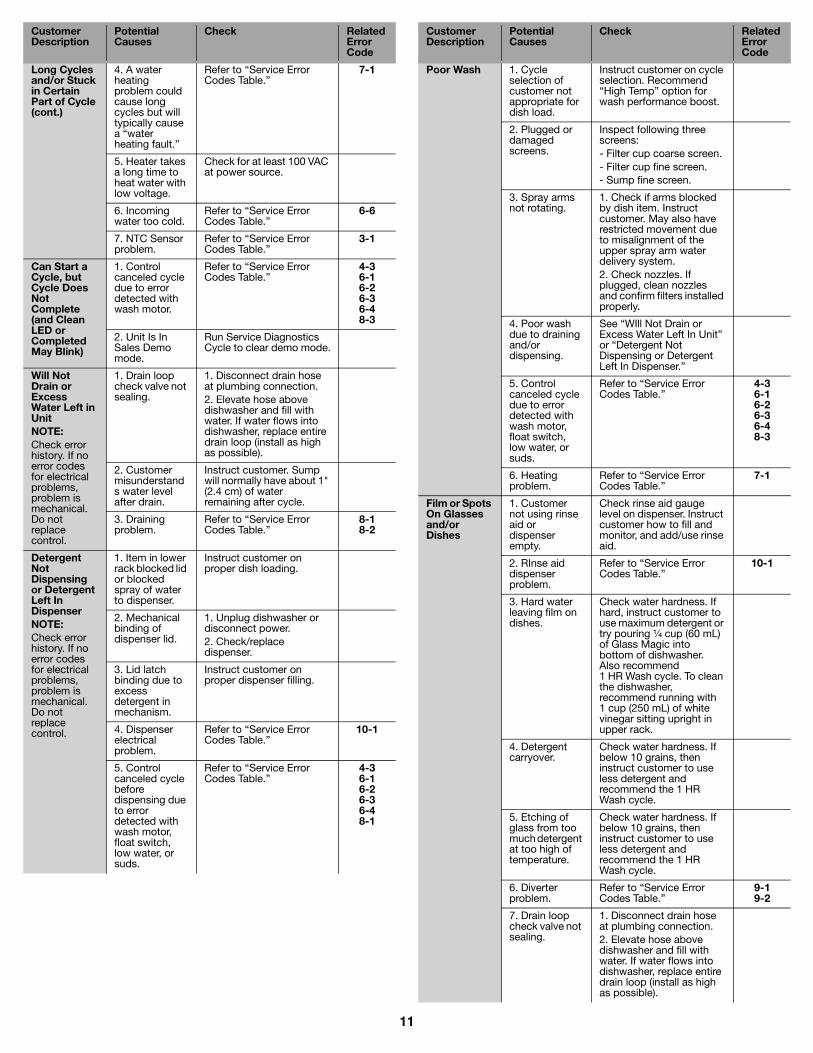
Long Cycles and/or Stuck in Certain Part of Cycle (cont.)
4. A water heating problem could cause long cycles but will typically cause a “water heating fault.”
Refer to “Service Error Codes Table.”
7-1
5. Heater takes a long time to heat water with low voltage.
Check for at least 100 VAC at power source.
6. Incoming water too cold.
Refer to “Service Error Codes Table.”
6-6
7. NTC Sensor problem.
Refer to “Service Error Codes Table.”
3-1
Can Start a Cycle, but Cycle Does Not Complete (and Clean LED or Completed May Blink)
1. Control canceled cycle due to error detected with wash motor.
Refer to “Service Error Codes Table.”
4-36-16-26-36-48-3
2. Unit Is In Sales Demo mode.
Run Service Diagnostics Cycle to clear demo mode.
Will Not Drain or Excess Water Left in UnitNOTE:Check error history. If no error codes for electrical problems, problem is mechanical. Do not replace control.
1. Drain loop check valve not sealing.
1. Disconnect drain hose at plumbing connection.2. Elevate hose above dishwasher and fill with water. If water flows into dishwasher, replace entire drain loop (install as high as possible).
2. Customer misunderstands water level after drain.
Instruct customer. Sump will normally have about 1" (2.4 cm) of water remaining after cycle.
3. Draining problem.
Refer to “Service Error Codes Table.”
8-18-2
Detergent Not Dispensing or Detergent Left In DispenserNOTE:Check error history. If no error codes for electrical problems, problem is mechanical. Do not replace control.
1. Item in lower rack blocked lid or blocked spray of water to dispenser.
Instruct customer on proper dish loading.
2. Mechanical binding of dispenser lid.
1. Unplug dishwasher or disconnect power.2. Check/replace dispenser.
3. Lid latch binding due to excess detergent in mechanism.
Instruct customer on proper dispenser filling.
4. Dispenser electrical problem.
Refer to “Service Error Codes Table.”
10-1
5. Control canceled cycle before dispensing due to error detected with wash motor, float switch, low water, or suds.
Refer to “Service Error Codes Table.”
4-36-16-26-36-48-1
Customer Description
Potential Causes
Check RelatedError Code
Poor Wash 1. Cycle selection of customer not appropriate for dish load.
Instruct customer on cycle selection. Recommend “High Temp” option for wash performance boost.
2. Plugged or damaged screens.
Inspect following three screens:- Filter cup coarse screen.- Filter cup fine screen.- Sump fine screen.
3. Spray arms not rotating.
1. Check if arms blocked by dish item. Instruct customer. May also have restricted movement due to misalignment of the upper spray arm water delivery system.2. Check nozzles. If plugged, clean nozzles and confirm filters installed properly.
4. Poor wash due to draining and/or dispensing.
See “WIll Not Drain or Excess Water Left In Unit” or “Detergent Not Dispensing or Detergent Left In Dispenser.”
5. Control canceled cycle due to error detected with wash motor, float switch, low water, or suds.
Refer to “Service Error Codes Table.”
4-36-16-26-36-48-3
6. Heating problem.
Refer to “Service Error Codes Table.”
7-1
Film or Spots On Glasses and/or Dishes
1. Customer not using rinse aid or dispenser empty.
Check rinse aid gauge level on dispenser. Instruct customer how to fill and monitor, and add/use rinse aid.
2. RInse aid dispenser problem.
Refer to “Service Error Codes Table.”
10-1
3. Hard water leaving film on dishes.
Check water hardness. If hard, instruct customer to use maximum detergent or try pouring ¹⁄₄ cup (60 mL) of Glass Magic into bottom of dishwasher. Also recommend 1 HR Wash cycle. To clean the dishwasher, recommend running with 1 cup (250 mL) of white vinegar sitting upright in upper rack.
4. Detergent carryover.
Check water hardness. If below 10 grains, then instruct customer to use less detergent and recommend the 1 HR Wash cycle.
5. Etching of glass from too much detergent at too high of temperature.
Check water hardness. If below 10 grains, then instruct customer to use less detergent and recommend the 1 HR Wash cycle.
6. Diverter problem.
Refer to “Service Error Codes Table.”
9-19-2
7. Drain loop check valve not sealing.
1. Disconnect drain hose at plumbing connection.2. Elevate hose above dishwasher and fill with water. If water flows into dishwasher, replace entire drain loop (install as high as possible).
Customer Description
Potential Causes
Check RelatedError Code
12
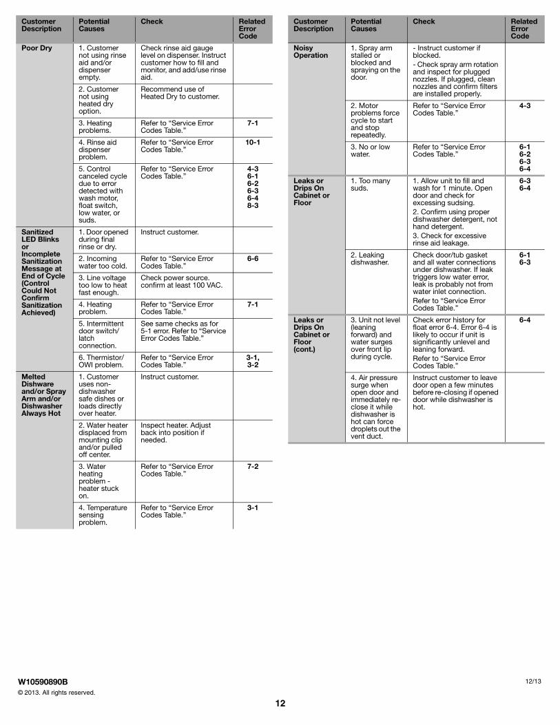
Poor Dry 1. Customer not using rinse aid and/or dispenser empty.
Check rinse aid gauge level on dispenser. Instruct customer how to fill and monitor, and add/use rinse aid.
2. Customer not using heated dry option.
Recommend use of Heated Dry to customer.
3. Heating problems.
Refer to “Service Error Codes Table.”
7-1
4. Rinse aid dispenser problem.
Refer to “Service Error Codes Table.”
10-1
5. Control canceled cycle due to error detected with wash motor, float switch, low water, or suds.
Refer to “Service Error Codes Table.”
4-36-16-26-36-48-3
Sanitized LED Blinks or Incomplete Sanitization Message at End of Cycle (Control Could Not Confirm Sanitization Achieved)
1. Door opened during final rinse or dry.
Instruct customer.
2. Incoming water too cold.
Refer to “Service Error Codes Table.”
6-6
3. Line voltage too low to heat fast enough.
Check power source. confirm at least 100 VAC.
4. Heating problem.
Refer to “Service Error Codes Table.”
7-1
5. Intermittent door switch/latch connection.
See same checks as for 5-1 error. Refer to “Service Error Codes Table.”
6. Thermistor/OWI problem.
Refer to “Service Error Codes Table.”
3-1,3-2
Melted Dishware and/or Spray Arm and/or Dishwasher Always Hot
1. Customer uses non-dishwasher safe dishes or loads directly over heater.
Instruct customer.
2. Water heater displaced from mounting clip and/or pulled off center.
Inspect heater. Adjust back into position if needed.
3. Water heating problem - heater stuck on.
Refer to “Service Error Codes Table.”
7-2
4. Temperature sensing problem.
Refer to “Service Error Codes Table.”
3-1
Customer Description
Potential Causes
Check RelatedError Code
Noisy Operation
1. Spray arm stalled or blocked and spraying on the door.
- Instruct customer if blocked.- Check spray arm rotation and inspect for plugged nozzles. If plugged, clean nozzles and confirm filters are installed properly.
2. Motor problems force cycle to start and stop repeatedly.
Refer to “Service Error Codes Table.”
4-3
3. No or low water.
Refer to “Service Error Codes Table.”
6-16-26-36-4
Leaks or Drips On Cabinet or Floor
1. Too many suds.
1. Allow unit to fill and wash for 1 minute. Open door and check for excessing sudsing.2. Confirm using proper dishwasher detergent, not hand detergent.3. Check for excessive rinse aid leakage.
6-36-4
2. Leaking dishwasher.
Check door/tub gasket and all water connections under dishwasher. If leak triggers low water error, leak is probably not from water inlet connection.Refer to “Service Error Codes Table.”
6-16-3
Leaks or Drips On Cabinet or Floor (cont.)
3. Unit not level (leaning forward) and water surges over front lip during cycle.
Check error history for float error 6-4. Error 6-4 is likely to occur if unit is significantly unlevel and leaning forward.Refer to “Service Error Codes Table.”
6-4
4. Air pressure surge when open door and immediately re-close it while dishwasher is hot can force droplets out the vent duct.
Instruct customer to leave door open a few minutes before re-closing if opened door while dishwasher is hot.
Customer Description
Potential Causes
Check RelatedError Code
W10590890B© 2013. All rights reserved.
12/13