For more information, please login
65
Shanghai Changjiang Electric Equipment Group Co., Ltd. Adopt ecological paper printing for this manual Address: No. 376, Xunye Road, Sheshan Industrial Zone, Songjiang District, Shanghai Website: www.chanko.com Service Hotline: 400-808-6488 Contact Number: 0086-21-57796223 Email: [email protected]; [email protected] SHANGHAI CHANGJIANG ELECTRIC EQUIPMENT GROUP CO., LTD.
Transcript of For more information, please login

Shanghai Changjiang Electric Equipment Group Co., Ltd.
Adopt ecological paper printing for this manual
Address: No. 376, Xunye Road, Sheshan Industrial Zone, Songjiang District, Shanghai
Website: www.chanko.com
Service Hotline: 400-808-6488
Contact Number: 0086-21-57796223
Email: [email protected]; [email protected]
SHANGHAI CHANGJIANG ELECTRIC EQUIPMENT GROUP CO., LTD.
SENSOR
Changjiang Sensor
Sensing The Future
SHANGHAI CHANGJIANG ELECTRIC EQUIPMENT GROUP CO., LTD.

For more information, please login www.chanko.comFor more information, please login www.chanko.com

For more information, please login www.chanko.comFor more information, please login www.chanko.com

About Changjiang Group
Shanghai Changjiang Electric Equipment Group Co., Ltd.
established in 1988, which is a leading supplier of industrial
automation, measurement and control sensors in China. It is
located in Shanghai Changjiang Industrial Science and
Technology Park. The park covers an area of more than 45000
square meters. After focusing on the accumulation and
deposition of electrical manufacturing for more than 30 years,
Changjiang Group has the advanced technology and the
outstanding quality of sensors in the industry now.
Changjiang mainly manufactures proximity sensor,
photoelectric sensor, capacitive sensor, fiber optic sensor, laser
sensor, safety screen and so on. Based on strong technical
advantages, Changjiang customizes the industrial
measurement and control sensing system according to
customer's requirements.
Contents
1
2
4
8
12
15
16
22
24
1. Overview
2. Model Naming
3. Cylindrical DC 3-Wire
CL08 Series, CL12 Series, CL18 Series, CL30 Series
4. Cylindrical DC 2-Wire
CL08 Series, CL12 Series, CL18 Series, CL30 Series
5. Cylindrical AC 2-Wire
CL12 Series, CL18 Series, CL30 Series
6. Rectangular DC 3-Wire
CL17 Series, CL25 Series, CL30 Series, CL40 Series
7. Outline Size and Output Circuit Diagram
8. Product Installation Method
9. Industry Application Case
10. Series of Photoelectric Sensors
Model naming
CPA cylindrical (18mm) photoelectric sensor
CPK rectangular photoelectric sensor
CPG U-shaped photoelectric sensor
Industry application case
11. Series of Fiber Optic Sensors
Model naming
CX6 fiber optic sensor
CX2 fiber cable series
Industry application case
26
29
31
33
35
36
37
48
50

1
Overview
Concept of Proximity Sensor
Features of Proximity Sensor
Basic Principle of Inductive Sensor
Movement Differential
Consumed Current
The current required in the working state of the sensor.
Leak Current
When the sensor is not turned on, the residual current in its load is called leak current.
Response Frequency
Response frequency is the maximum number of actions per second of the sensor.
Inductive sensor is a kind of proximity sensor.
Proximity sensor is used to detect the proximity of objects and control the switch under the
condition of non-contact by using the sensitive characteristics of sensors to close objects. In the
common proximity sensor, according to the principle of induction, the proximity sensor can be
divided into three types: high frequency oscillation, magnetic induction and electrostatic capacitance.
◆ No mechanical contact, low power Consumed and long life.
◆ Suitable for harsh working environment, reliable work.
◆ High repeatability of the detection, can accurately judge the location of the object.
◆ High response frequency, suitable for fast moving object detection.
High frequency alternating magnetic field is generated in the front-end detection coil. When the
metal object is close to the magnetic field, eddy current is generated inside the metal object due to
electromagnetic induction, leading to the attenuation of magnetic field energy, which is called eddy
current loss. When the sensing surface of the proximity sensor is constantly close to the metal object,
the attenuation of the magnetic field energy of the metal object is constantly increasing. When the
attenuation reaches a certain degree, the sensor triggers the switch to output signals, so as to detect
the presence or absence of the object.
The difference between the induction distance when the proximity switch operates and the
distance generated when the proximity switch is reset is the response distance. The response
distance of the proximity switch is the response distance measured when the standard detection
object is used.
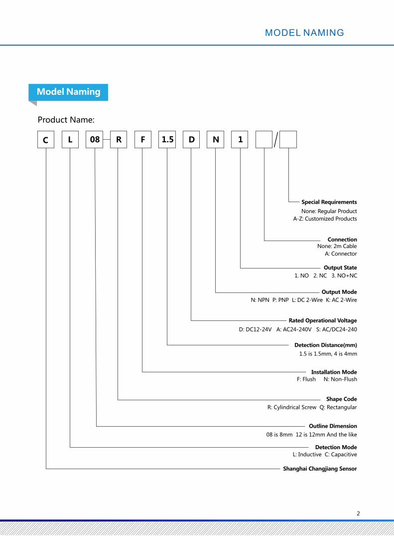
Special Requirements
D: DC12-24V A: AC24-240V S: AC/DC24-240
1.5 is 1.5mm, 4 is 4mm
C L 08 R F 1.5 D N 1
None: Regular Product
A-Z: Customized Products
ConnectionNone: 2m Cable
A: Connector
Output State
1. NO 2. NC 3. NO+NC
Output Mode
N: NPN P: PNP L: DC 2-Wire K: AC 2-Wire
Rated Operational Voltage
Detection Distance(mm)
F: Flush N: Non-Flush
Installation Mode
R: Cylindrical Screw Q: Rectangular
Shape Code
08 is 8mm 12 is 12mm And the like
Outline Dimension
L: Inductive C: Capacitive
Detection Mode
Shanghai Changjiang Sensor
2
Product Name:
MODEL NAMING
Model Naming
1
Overview
Concept of Proximity Sensor
Features of Proximity Sensor
Basic Principle of Inductive Sensor
Movement Differential
Consumed Current
The current required in the working state of the sensor.
Leak Current
When the sensor is not turned on, the residual current in its load is called leak current.
Response Frequency
Response frequency is the maximum number of actions per second of the sensor.
Inductive sensor is a kind of proximity sensor.
Proximity sensor is used to detect the proximity of objects and control the switch under the
condition of non-contact by using the sensitive characteristics of sensors to close objects. In the
common proximity sensor, according to the principle of induction, the proximity sensor can be
divided into three types: high frequency oscillation, magnetic induction and electrostatic capacitance.
◆ No mechanical contact, low power Consumed and long life.
◆ Suitable for harsh working environment, reliable work.
◆ High repeatability of the detection, can accurately judge the location of the object.
◆ High response frequency, suitable for fast moving object detection.
High frequency alternating magnetic field is generated in the front-end detection coil. When the
metal object is close to the magnetic field, eddy current is generated inside the metal object due to
electromagnetic induction, leading to the attenuation of magnetic field energy, which is called eddy
current loss. When the sensing surface of the proximity sensor is constantly close to the metal object,
the attenuation of the magnetic field energy of the metal object is constantly increasing. When the
attenuation reaches a certain degree, the sensor triggers the switch to output signals, so as to detect
the presence or absence of the object.
The difference between the induction distance when the proximity switch operates and the
distance generated when the proximity switch is reset is the response distance. The response
distance of the proximity switch is the response distance measured when the standard detection
object is used.
Special Requirements
D: DC12-24V A: AC24-240V S: AC/DC24-240
1.5 is 1.5mm, 4 is 4mm
C L 08 R F 1.5 D N 1
None: Regular Product
A-Z: Customized Products
ConnectionNone: 2m Cable
A: Connector
Output State
1. NO 2. NC 3. NO+NC
Output Mode
N: NPN P: PNP L: DC 2-Wire K: AC 2-Wire
Rated Operational Voltage
Detection Distance(mm)
F: Flush N: Non-Flush
Installation Mode
R: Cylindrical Screw Q: Rectangular
Shape Code
08 is 8mm 12 is 12mm And the like
Outline Dimension
L: Inductive C: Capacitive
Detection Mode
Shanghai Changjiang Sensor
2
Product Name:
MODEL NAMING
Model Naming

Standard Function Type
◆ The non-contact detection method is safe and reliable.
The special IC is used to design and manufacture to improve the anti-interference performance.◆
Durable and high reliable, can replace small switches and limit switches.◆
Full Specification:
The cylindrical series M08 to M30mm and the series 17*17 to 40*40 mm.rectangular
3
Inductive Sensor
4
Protection Circuit
Weight
Material
Switching Capacity
Size (mm)
NPN NO
NPN NC
PNP NO
PNP NC
1.5mm±10%
0~1.2mm
Iron 8×8×1mm
2kHz
2mm±10% 1.5mm±10% 2mm±10%
0~1.6mm 0~1.2mm 0~1.6mm
Iron 12×12×1mm Iron 8×8×1mm Iron 12×12×1mm
0.8kHz
CL08 CL08 CL08 CL08
CL08-RF1.5DN1
CL08-RF1.5DP1
CL08-RF1.5DP2
CL08-RF1.5DN2
CL08-RN2DN1
CL08-RN2DP1
CL08-RN2DP2
CL08-RN2DN2
CL08-RF1.5DN1-A
CL08-RF1.5DN2-A
CL08-RF1.5DP1-A
CL08-RF1.5DP2-A
CL08-RN2DN1-A
CL08-RN2DN2-A
CL08-RN2DP1-A
CL08-RN2DP2-A
M8*1*35 M8*1*35 M8*1*50 M8*1*50
DC12-24V ripple (P-P) less than 10% (DC10-30V)
Temperature range from-25 ℃ to 70 ℃ is 23 ℃, the detection distance is less than ±10%.
300m/s² for each 10 times in X / Y / Z directions
IEC standard IP67
2m PVC cable 2m PVC cable M8 3 pins connector M8 3 pins connector
Case: nickel-plated brass, Test surface: heat-resistant ABS, standard cable (black) PVC
About 32g About 31g About 7g About 7g
Less than 10% of detection distance
0.8kHz 2kHz
Inductive Sensor-Cylindrical
◆ High accuracy of repetition
◆ Low temperature drift
◆ Strong anti-interference ability
◆ High response frequency
◆ 2m standard cable
◆ Strong and durable structure, stable and reliable performance,
good consistency, high cost performance
Less than 200mA
Less than 13mA
Action display (red)
Less than 2V (load current 200mA, conductor 2m)
Reverse protection, surge absorption, load short circuit protection
Working: -25~+70℃, Storing: -40~+85℃(no freeze, no dew)
Working / Storing: 35~95%RH (no dew)
Connection Mode
IP Grade
Vibration (Durability)
Impact (Durability)
Withstand Voltage
Insulation Resistance
Influence of Voltage
Temperature Effect
Ambient Temperature Range
Indicator
Ambient Humidity Range
Control
Output Residual Voltage
Product No.
Installation Mode
Detection Distance
Setting Distance
Output Mode
Output Mode
Technical Parameter
Standard Detection Object
Response Frequency
Movement Differential
Supply Voltage Service Voltage Range
Consumed Current
Non-flushFlush Non-flush Flush
Inductive Sensor-Cylindrical
Above 50MΩ(DC500Vmegger)between the whole charging part and the shell
AC 1, 000V 50/60Hz 1min between the whole charging part and the shell
Up and down 1.5mm at 10~55Hz for each 2 hours in X / Y / Z directions
DC 3-Wire
In the range of ±15% of the rated power supply voltage, the detection distance is less than ±1%.

5
NPN NO
NPN NC
PNP NO
PNP NC
Case: nickel-plated brass, Test surface: heat-resistant ABS, standard cable (black) PVC
About 54g About 52g About15g About 14g
DC 3-Wire
Inductive Sensor-Cylindrical
◆ The measurement deviation between the same type of sensor is very small
◆ Low temperature drift
◆ Strong anti-interference ability
◆ High response frequency
◆ Bilateral indicator light structure
◆ 2m standard cable
◆ Strong and durable structure, stable and reliable performance,
good consistency, high cost performance
2mm±10%
0~1.6mm
Iron 12×12×1mm
1.5kHz
4mm±10%4mm±10% 2mm±10%
0~3.2mm0~3.2mm 0~1.6mm
Iron 15×15×1mmIron 15×15×1mm Iron 12×12×1mm
0.4kHz0.4kHz 1.5kHz
Less than 13mA
Less than 200mA
Less than 2V (Load current 200mA, conductor 2m)
Action display (red)
Reverse protection, surge absorption, load short circuit protection
Working: -25~+70℃ Storing: -40 ~ +85 ℃ (no freeze, no dew)
Working / Storing: 35~95%RH (no dew)
DC12-24V ripple (P-P) less than 10% (DC10-30V)
Temperature range from-25 ℃ to 70 ℃ is 23 ℃, the detection distance is less than ±10%.
In the range of ±15% of the rated power supply voltage, the detection distance is less than ±1%.
IEC Standard IP67
CL12 CL12 CL12CL12
CL12-RF2DN1 CL12-RN4DN1
CL12-RF2DP1
CL12-RF2DP2
CL12-RF2DN2
CL12-RN4DN1-A
CL12-RN4DP1
CL12-RN4DP2
CL12-RN4DN2
CL12-RF2DN1-A
CL12-RF2DN2-A
CL12-RF2DP1-A
CL12-RF2DP2-A
CL12-RN4DN2-A
CL12-RN4DP1-A
CL12-RN4DP2-A
M12*1*42 M12*1*42 M12*1*58M12*1*55
Protection Circuit
Weight
Material
Switching Capacity
Size (mm)
Connection Mode
IP Grade
Vibration (Durability)
Impact (Durability)
Withstand Voltage
Insulation Resistance
Influence of Voltage
Temperature Effect
Ambient Temperature Range
Indicator
Ambient Humidity Range
Control
Output Residual Voltage
Product No.
Installation Mode
Detection Distance
Setting Distance
Output Mode
Output Mode
Technical Parameter
Standard Detection Object
Response Frequency
Movement Differential
Supply Voltage Service Voltage Range
Consumed Current
Less than 10% of detection distance
2 m of PVC cable 2 m of PVC cable M12 4 pins connector M12 4 pins connector
Non-flush Non-flushFlush Flush
Above 50MΩ(DC500Vmegger)between the whole charging part and the shell
AC 1, 000V 50/60Hz 1min between the whole charging part and the shell
300m/s² for each 10 times in X / Y / Z directions
Up and down 1.5mm at 10~55Hz for each 2 hours in X / Y / Z directions
DC 3-Wire
NPN NO
NPN NC
PNP NO
PNP NC
CL18-RN8DN1-A
CL18-RN8DN2-A
CL18-RN8DP1-A
CL18-RN8DP2-A
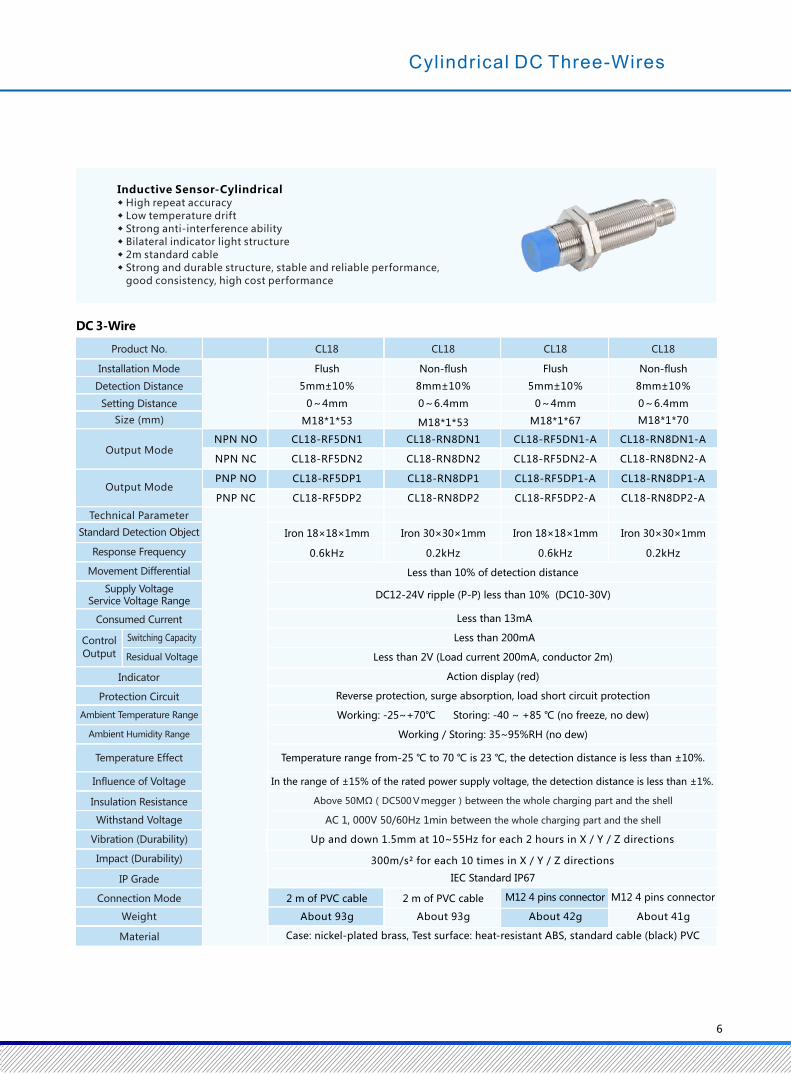
5mm±10%
0~4mm
Iron 18×18×1mm
0.6kHz
8mm±10% 5mm±10% 8mm±10%
0~6.4mm 0~4mm 0~6.4mm
Iron 30×30×1mm Iron 18×18×1mm Iron 30×30×1mm
0.2kHz 0.6kHz 0.2kHz
CL18 CL18 CL18
CL18-RF5DN1
CL18-RF5DP1
CL18-RF5DP2
CL18-RF5DN2
CL18-RN8DN1
CL18-RN8DP1
CL18-RN8DP2
CL18-RN8DN2
CL18-RF5DN1-A
CL18-RF5DN2-A
CL18-RF5DP1-A
CL18-RF5DP2-A
M18*1*53 M18*1*67 M18*1*70M18*1*53
CL18
6
Protection Circuit
Weight
Material
Switching Capacity
Size (mm)
Connection Mode
IP Grade
Vibration (Durability)
Impact (Durability)
Withstand Voltage
Insulation Resistance
Influence of Voltage
Temperature Effect
Ambient Temperature Range
Indicator
Ambient Humidity Range
Control
Output Residual Voltage
Product No.
Installation Mode
Detection Distance
Setting Distance
Output Mode
Output Mode
Technical Parameter
Standard Detection Object
Response Frequency
Movement Differential
Supply Voltage Service Voltage Range
Consumed Current
Less than 10% of detection distance
DC12-24V ripple (P-P) less than 10% (DC10-30V)
Less than 13mA
Less than 200mA
Less than 2V (Load current 200mA, conductor 2m)
Action display (red)
Reverse protection, surge absorption, load short circuit protection
Working: -25~+70℃ Storing: -40 ~ +85 ℃ (no freeze, no dew)
Working / Storing: 35~95%RH (no dew)
Temperature range from-25 ℃ to 70 ℃ is 23 ℃, the detection distance is less than ±10%.
IEC Standard IP67
M12 4 pins connectorM12 4 pins connector2 m of PVC cable2 m of PVC cable
About 93g About 93g About 42g About 41g
Case: nickel-plated brass, Test surface: heat-resistant ABS, standard cable (black) PVC
◆ High repeat accuracy
◆ Low temperature drift
◆ Strong anti-interference ability
◆ Bilateral indicator light structure
◆ 2m standard cable
◆ Strong and durable structure, stable and reliable performance,
good consistency, high cost performance
Inductive Sensor-Cylindrical
Cylindrical DC Three-Wires
Non-flushFlush Non-flush Flush
Above 50MΩ(DC500Vmegger)between the whole charging part and the shell
AC 1, 000V 50/60Hz 1min between the whole charging part and the shell
300m/s² for each 10 times in X / Y / Z directions
Up and down 1.5mm at 10~55Hz for each 2 hours in X / Y / Z directions
In the range of ±15% of the rated power supply voltage, the detection distance is less than ±1%.
5
NPN NO
NPN NC
PNP NO
PNP NC
Case: nickel-plated brass, Test surface: heat-resistant ABS, standard cable (black) PVC
About 54g About 52g About15g About 14g
DC 3-Wire
Inductive Sensor-Cylindrical
◆ The measurement deviation between the same type of sensor is very small
◆ Low temperature drift
◆ Strong anti-interference ability
◆ High response frequency
◆ Bilateral indicator light structure
◆ 2m standard cable
◆ Strong and durable structure, stable and reliable performance,
good consistency, high cost performance
2mm±10%
0~1.6mm
Iron 12×12×1mm
1.5kHz
4mm±10%4mm±10% 2mm±10%
0~3.2mm0~3.2mm 0~1.6mm
Iron 15×15×1mmIron 15×15×1mm Iron 12×12×1mm
0.4kHz0.4kHz 1.5kHz
Less than 13mA
Less than 200mA
Less than 2V (Load current 200mA, conductor 2m)
Action display (red)
Reverse protection, surge absorption, load short circuit protection
Working: -25~+70℃ Storing: -40 ~ +85 ℃ (no freeze, no dew)
Working / Storing: 35~95%RH (no dew)
DC12-24V ripple (P-P) less than 10% (DC10-30V)
Temperature range from-25 ℃ to 70 ℃ is 23 ℃, the detection distance is less than ±10%.
In the range of ±15% of the rated power supply voltage, the detection distance is less than ±1%.
IEC Standard IP67
CL12 CL12 CL12CL12
CL12-RF2DN1 CL12-RN4DN1
CL12-RF2DP1
CL12-RF2DP2
CL12-RF2DN2
CL12-RN4DN1-A
CL12-RN4DP1
CL12-RN4DP2
CL12-RN4DN2
CL12-RF2DN1-A
CL12-RF2DN2-A
CL12-RF2DP1-A
CL12-RF2DP2-A
CL12-RN4DN2-A
CL12-RN4DP1-A
CL12-RN4DP2-A
M12*1*42 M12*1*42 M12*1*58M12*1*55
Protection Circuit
Weight
Material
Switching Capacity
Size (mm)
Connection Mode
IP Grade
Vibration (Durability)
Impact (Durability)
Withstand Voltage
Insulation Resistance
Influence of Voltage
Temperature Effect
Ambient Temperature Range
Indicator
Ambient Humidity Range
Control
Output Residual Voltage
Product No.
Installation Mode
Detection Distance
Setting Distance
Output Mode
Output Mode
Technical Parameter
Standard Detection Object
Response Frequency
Movement Differential
Supply Voltage Service Voltage Range
Consumed Current
Less than 10% of detection distance
2 m of PVC cable 2 m of PVC cable M12 4 pins connector M12 4 pins connector
Non-flush Non-flushFlush Flush
Above 50MΩ(DC500Vmegger)between the whole charging part and the shell
AC 1, 000V 50/60Hz 1min between the whole charging part and the shell
300m/s² for each 10 times in X / Y / Z directions
Up and down 1.5mm at 10~55Hz for each 2 hours in X / Y / Z directions
DC 3-Wire
NPN NO
NPN NC
PNP NO
PNP NC
CL18-RN8DN1-A
CL18-RN8DN2-A
CL18-RN8DP1-A
CL18-RN8DP2-A
5mm±10%
0~4mm
Iron 18×18×1mm
0.6kHz
8mm±10% 5mm±10% 8mm±10%
0~6.4mm 0~4mm 0~6.4mm
Iron 30×30×1mm Iron 18×18×1mm Iron 30×30×1mm
0.2kHz 0.6kHz 0.2kHz
CL18 CL18 CL18
CL18-RF5DN1
CL18-RF5DP1
CL18-RF5DP2
CL18-RF5DN2
CL18-RN8DN1
CL18-RN8DP1
CL18-RN8DP2
CL18-RN8DN2
CL18-RF5DN1-A
CL18-RF5DN2-A
CL18-RF5DP1-A
CL18-RF5DP2-A
M18*1*53 M18*1*67 M18*1*70M18*1*53
CL18
6
Protection Circuit
Weight
Material
Switching Capacity
Size (mm)
Connection Mode
IP Grade
Vibration (Durability)
Impact (Durability)
Withstand Voltage
Insulation Resistance
Influence of Voltage
Temperature Effect
Ambient Temperature Range
Indicator
Ambient Humidity Range
Control
Output Residual Voltage
Product No.
Installation Mode
Detection Distance
Setting Distance
Output Mode
Output Mode
Technical Parameter
Standard Detection Object
Response Frequency
Movement Differential
Supply Voltage Service Voltage Range
Consumed Current
Less than 10% of detection distance
DC12-24V ripple (P-P) less than 10% (DC10-30V)
Less than 13mA
Less than 200mA
Less than 2V (Load current 200mA, conductor 2m)
Action display (red)
Reverse protection, surge absorption, load short circuit protection
Working: -25~+70℃ Storing: -40 ~ +85 ℃ (no freeze, no dew)
Working / Storing: 35~95%RH (no dew)
Temperature range from-25 ℃ to 70 ℃ is 23 ℃, the detection distance is less than ±10%.
IEC Standard IP67
M12 4 pins connectorM12 4 pins connector2 m of PVC cable2 m of PVC cable
About 93g About 93g About 42g About 41g
Case: nickel-plated brass, Test surface: heat-resistant ABS, standard cable (black) PVC
◆ High repeat accuracy
◆ Low temperature drift
◆ Strong anti-interference ability
◆ Bilateral indicator light structure
◆ 2m standard cable
◆ Strong and durable structure, stable and reliable performance,
good consistency, high cost performance
Inductive Sensor-Cylindrical
Cylindrical DC Three-Wires
Non-flushFlush Non-flush Flush
Above 50MΩ(DC500Vmegger)between the whole charging part and the shell
AC 1, 000V 50/60Hz 1min between the whole charging part and the shell
300m/s² for each 10 times in X / Y / Z directions
Up and down 1.5mm at 10~55Hz for each 2 hours in X / Y / Z directions
In the range of ±15% of the rated power supply voltage, the detection distance is less than ±1%.

DC 3-Wire
7
NPN NO
NPN NC
PNP NO
PNP NC
10mm±10%
0~8mm
Iron 30×30×1mm
0.4kHz
15mm±10% 10mm±10% 15mm±10%
0~12mm 0~8mm
Iron 54×54×1mm Iron 30×30×1mm Iron 54×54×1mm
0.1kHz 0.4kHz 0.1kHz
CL30 CL30 CL30 CL30
CL30-RF10DN1
CL30-RF10DP1
CL30-RF10DP2
CL30-RF10DN2
CL30-RN15DN1
CL30-RN15DP1
CL30-RN15DP2
CL30-RN15DN2
CL30-RF10DN1-A
CL30-RF10DN2-A
CL30-RF10DP1-A
CL30-RF10DP2-A
M30*1.5*66 M30*1.5*68 M30*1.5*84 M30*1.5*90
159g
CL30-RN15DN1-A
CL30-RN15DN2-A
CL30-RN15DP1-A
CL30-RN15DP2-A
0~12mm
Less than 10% of detection distance
DC12-24V ripple (P-P) less than 10% (DC10-30V)
Less than 13mA
Less than 200mA
Less than 2V (Load current 200mA, conductor 2m)
Action display (red)
Reverse protection, surge absorption, load short circuit protection
Working: -25~+70℃ Storing: -40 ~ +85 ℃ (no freeze, no dew)
Working / Storing: 35~95%RH (no dew)
M12 4 pins connector2 m of PVC cable2 m of PVC cable
Temperature range from-25 ℃ to 70 ℃ is 23 ℃, the detection distance is less than ±10%.
IEC Standard IP67
M12 4 pins connector
About 168g About 127g About 128g
Case: nickel-plated brass, Test surface: heat-resistant ABS, standard cable (black) PVC
Protection Circuit
Weight
Material
Switching Capacity
Size (mm)
Connection Mode
IP Grade
Vibration (Durability)
Impact (Durability)
Withstand Voltage
Insulation Resistance
Influence of Voltage
Temperature Effect
Ambient Temperature Range
Indicator
Ambient Humidity Range
Control
Output Residual Voltage
Product No.
Installation Mode
Detection Distance
Setting Distance
Output Mode
Output Mode
Technical Parameter
Standard Detection Object
Response Frequency
Movement Differential
Supply Voltage Service Voltage Range
Consumed Current
Non-flush Non-flushFlush Flush
Above 50MΩ(DC500Vmegger)between the whole charging part and the shell
AC 1, 000V 50/60Hz 1min between the whole charging part and the shell
◆ The measurement deviation between the same type of sensor is small◆ Low temperature drift◆ Strong anti-interference ability◆ Double side indicator structure◆ 2m standard cable◆ Strong and durable structure, stable and reliable performance, good consistency, high cost performance
Inductive Sensor-Cylindrical
300m/s² for each 10 times in X / Y / Z directions
Up and down 1.5mm at 10~55Hz for each 2 hours in X / Y / Z directions
In the range of ±15% of the rated power supply voltage, the detection distance is less than ±1%.
DC 2-Wire
8
1.5mm±10%
0~1.2mm
Iron 8×8×1mm
1.5kHz
2mm±10% 1.5mm±10% 2mm±10%
0~1.6mm 0~1.2mm 0~1.6mm
Iron 12×12×1mm Iron 8×8×1mm Iron 12×12×1mm
0.8kHz 1.5kHz 0.8kHz
Less than 0.8mA
3-100mA
Less than 3V (less than 5V), (load current 100mA, conductor 2m )
Action display (red)
Reverse protection, surge absorption, load short circuit protection
Working: -25~+70℃ Storing: -40 ~ +85 ℃ (no freeze, no dew)
Working / Storing: 35~95%RH (no dew)
Temperature range from-25 ℃ to 70 ℃ is 23 ℃, the detection distance is less than ±10%.
IEC Standard IP67
2 m of PVC cable 2 m of PVC cable M8 3 pins connector M8 3 pins connector
Case: brass nickel plated, Test surface: heat-resistant ABS, standard cable (black) PVC
CL08 CL08 CL08 CL08
CL08-RF1.5DL1
CL08-RF1.5DL2
CL08-RN2DL1
CL08-RN2DL2
CL08-RF1.5DL1-A
CL08-RF1.5DL2-A
CL08-RN2DL1-A
CL08-RN2DL2-A
M8*1*35 M8*1*35 M8*1*50 M8*1*50
About 32g About 31g About 7g About 7g
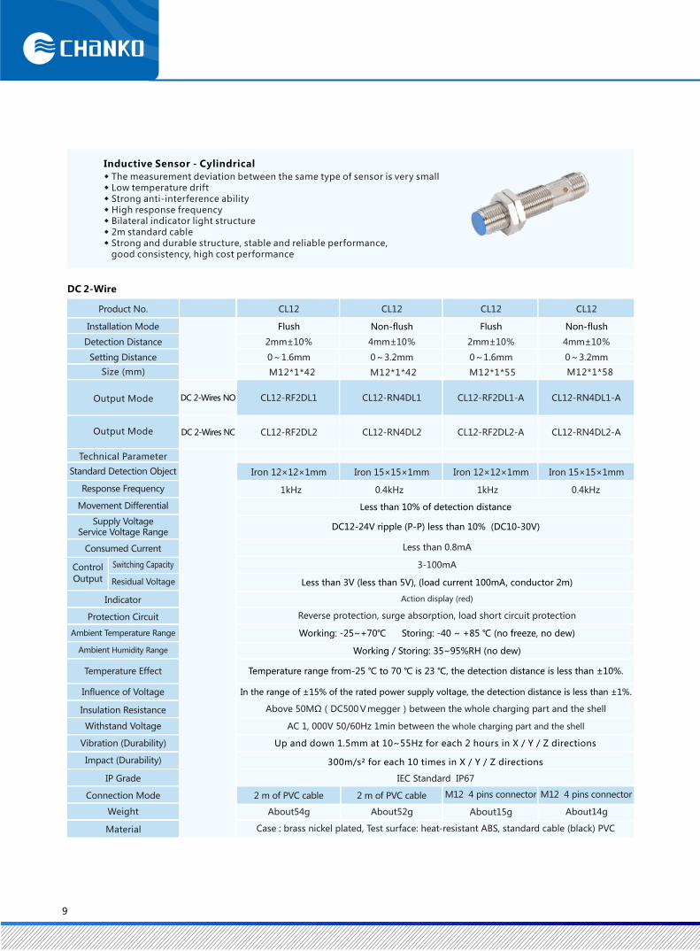
Inductive Sensor - Cylindrical
◆ High repeat accuracy◆ Low temperature drift◆ Strong anti-interference ability◆ High response frequency◆ 2m standard cable◆ Strong and durable structure, stable and reliable performance, good consistency, high cost performance
Protection Circuit
Weight
Material
Switching Capacity
Size (mm)
Connection Mode
IP Grade
Vibration (Durability)
Impact (Durability)
Withstand Voltage
Insulation Resistance
Influence of Voltage
Temperature Effect
Ambient Temperature Range
Indicator
Ambient Humidity Range
Control
Output Residual Voltage
Product No.
Installation Mode
Detection Distance
Setting Distance
Output Mode
Output Mode
Technical Parameter
Standard Detection Object
Response Frequency
Movement Differential
Supply Voltage Service Voltage Range
Consumed Current
Less than 10% of detection distance
DC12-24V ripple (P-P) less than 10% (DC10-30V)
DC 2-Wires NO
DC 2-Wires NC
Non-flushFlush Non-flush Flush
Inductive Sensor - Cylindrical
Above 50MΩ(DC500Vmegger)between the whole charging part and the shell
AC 1, 000V 50/60Hz 1min between the whole charging part and the shell
300m/s² for each 10 times in X / Y / Z directions
Up and down 1.5mm at 10~55Hz for each 2 hours in X / Y / Z directions
In the range of ±15% of the rated power supply voltage, the detection distance is less than ±1%.

DC 3-Wire
7
NPN NO
NPN NC
PNP NO
PNP NC
10mm±10%
0~8mm
Iron 30×30×1mm
0.4kHz
15mm±10% 10mm±10% 15mm±10%
0~12mm 0~8mm
Iron 54×54×1mm Iron 30×30×1mm Iron 54×54×1mm
0.1kHz 0.4kHz 0.1kHz
CL30 CL30 CL30 CL30
CL30-RF10DN1
CL30-RF10DP1
CL30-RF10DP2
CL30-RF10DN2
CL30-RN15DN1
CL30-RN15DP1
CL30-RN15DP2
CL30-RN15DN2
CL30-RF10DN1-A
CL30-RF10DN2-A
CL30-RF10DP1-A
CL30-RF10DP2-A
M30*1.5*66 M30*1.5*68 M30*1.5*84 M30*1.5*90
159g
CL30-RN15DN1-A
CL30-RN15DN2-A
CL30-RN15DP1-A
CL30-RN15DP2-A
0~12mm
Less than 10% of detection distance
DC12-24V ripple (P-P) less than 10% (DC10-30V)
Less than 13mA
Less than 200mA
Less than 2V (Load current 200mA, conductor 2m)
Action display (red)
Reverse protection, surge absorption, load short circuit protection
Working: -25~+70℃ Storing: -40 ~ +85 ℃ (no freeze, no dew)
Working / Storing: 35~95%RH (no dew)
M12 4 pins connector2 m of PVC cable2 m of PVC cable
Temperature range from-25 ℃ to 70 ℃ is 23 ℃, the detection distance is less than ±10%.
IEC Standard IP67
M12 4 pins connector
About 168g About 127g About 128g
Case: nickel-plated brass, Test surface: heat-resistant ABS, standard cable (black) PVC
Protection Circuit
Weight
Material
Switching Capacity
Size (mm)
Connection Mode
IP Grade
Vibration (Durability)
Impact (Durability)
Withstand Voltage
Insulation Resistance
Influence of Voltage
Temperature Effect
Ambient Temperature Range
Indicator
Ambient Humidity Range
Control
Output Residual Voltage
Product No.
Installation Mode
Detection Distance
Setting Distance
Output Mode
Output Mode
Technical Parameter
Standard Detection Object
Response Frequency
Movement Differential
Supply Voltage Service Voltage Range
Consumed Current
Non-flush Non-flushFlush Flush
Above 50MΩ(DC500Vmegger)between the whole charging part and the shell
AC 1, 000V 50/60Hz 1min between the whole charging part and the shell
◆ The measurement deviation between the same type of sensor is small◆ Low temperature drift◆ Strong anti-interference ability◆ Double side indicator structure◆ 2m standard cable◆ Strong and durable structure, stable and reliable performance, good consistency, high cost performance
Inductive Sensor-Cylindrical
300m/s² for each 10 times in X / Y / Z directions
Up and down 1.5mm at 10~55Hz for each 2 hours in X / Y / Z directions
In the range of ±15% of the rated power supply voltage, the detection distance is less than ±1%.
DC 2-Wire
8
1.5mm±10%
0~1.2mm
Iron 8×8×1mm
1.5kHz
2mm±10% 1.5mm±10% 2mm±10%
0~1.6mm 0~1.2mm 0~1.6mm
Iron 12×12×1mm Iron 8×8×1mm Iron 12×12×1mm
0.8kHz 1.5kHz 0.8kHz
Less than 0.8mA
3-100mA
Less than 3V (less than 5V), (load current 100mA, conductor 2m )
Action display (red)
Reverse protection, surge absorption, load short circuit protection
Working: -25~+70℃ Storing: -40 ~ +85 ℃ (no freeze, no dew)
Working / Storing: 35~95%RH (no dew)
Temperature range from-25 ℃ to 70 ℃ is 23 ℃, the detection distance is less than ±10%.
IEC Standard IP67
2 m of PVC cable 2 m of PVC cable M8 3 pins connector M8 3 pins connector
Case: brass nickel plated, Test surface: heat-resistant ABS, standard cable (black) PVC
CL08 CL08 CL08 CL08
CL08-RF1.5DL1
CL08-RF1.5DL2
CL08-RN2DL1
CL08-RN2DL2
CL08-RF1.5DL1-A
CL08-RF1.5DL2-A
CL08-RN2DL1-A
CL08-RN2DL2-A
M8*1*35 M8*1*35 M8*1*50 M8*1*50
About 32g About 31g About 7g About 7g
Inductive Sensor - Cylindrical
◆ High repeat accuracy◆ Low temperature drift◆ Strong anti-interference ability◆ High response frequency◆ 2m standard cable◆ Strong and durable structure, stable and reliable performance, good consistency, high cost performance
Protection Circuit
Weight
Material
Switching Capacity
Size (mm)
Connection Mode
IP Grade
Vibration (Durability)
Impact (Durability)
Withstand Voltage
Insulation Resistance
Influence of Voltage
Temperature Effect
Ambient Temperature Range
Indicator
Ambient Humidity Range
Control
Output Residual Voltage
Product No.
Installation Mode
Detection Distance
Setting Distance
Output Mode
Output Mode
Technical Parameter
Standard Detection Object
Response Frequency
Movement Differential
Supply Voltage Service Voltage Range
Consumed Current
Less than 10% of detection distance
DC12-24V ripple (P-P) less than 10% (DC10-30V)
DC 2-Wires NO
DC 2-Wires NC
Non-flushFlush Non-flush Flush
Inductive Sensor - Cylindrical
Above 50MΩ(DC500Vmegger)between the whole charging part and the shell
AC 1, 000V 50/60Hz 1min between the whole charging part and the shell
300m/s² for each 10 times in X / Y / Z directions
Up and down 1.5mm at 10~55Hz for each 2 hours in X / Y / Z directions
In the range of ±15% of the rated power supply voltage, the detection distance is less than ±1%.
9
2mm±10%
0~1.6mm
Iron 12×12×1mm
1kHz
4mm±10% 2mm±10% 4mm±10%
0~3.2mm 0~1.6mm 0~3.2mm
Iron 15×15×1mm Iron 12×12×1mm Iron 15×15×1mm
0.4kHz 1kHz 0.4kHz
Less than 0.8mA
3-100mA
Less than 3V (less than 5V), (load current 100mA, conductor 2m)
Action display (red)
Reverse protection, surge absorption, load short circuit protection
Working: -25~+70℃ Storing: -40 ~ +85 ℃ (no freeze, no dew)
Working / Storing: 35~95%RH (no dew)
IEC Standard IP67
2 m of PVC cable 2 m of PVC cable M12 4 pins connector M12 4 pins connector
Case : brass nickel plated, Test surface: heat-resistant ABS, standard cable (black) PVC
CL12 CL12 CL12 CL12
CL12-RF2DL1 CL12-RN4DL1 CL12-RF2DL1-A CL12-RN4DL1-A
About54g About52g About15g About14g
CL12-RF2DL2 CL12-RN4DL2 CL12-RF2DL2-A CL12-RN4DL2-A
M12*1*42 M12*1*42 M12*1*55 M12*1*58
Inductive Sensor - Cylindrical
◆ The measurement deviation between the same type of sensor is very small
◆ Low temperature drift
◆ Strong anti-interference ability
◆ High response frequency
◆ Bilateral indicator light structure
◆ 2m standard cable
◆ Strong and durable structure, stable and reliable performance,
good consistency, high cost performance
Protection Circuit
Weight
Material
Switching Capacity
Size (mm)
Connection Mode
IP Grade
Vibration (Durability)
Impact (Durability)
Withstand Voltage
Insulation Resistance
Influence of Voltage
Temperature Effect
Ambient Temperature Range
Indicator
Ambient Humidity Range
Control
Output Residual Voltage
Product No.
Installation Mode
Detection Distance
Setting Distance
Output Mode
Output Mode
Technical Parameter
Standard Detection Object
Response Frequency
Movement Differential
Supply Voltage Service Voltage Range
Consumed Current
Less than 10% of detection distance
DC12-24V ripple (P-P) less than 10% (DC10-30V)
DC 2-Wire
DC 2-Wires NO
DC 2-Wires NC
Non-flush Non-flushFlush Flush
Above 50MΩ(DC500Vmegger)between the whole charging part and the shell
AC 1, 000V 50/60Hz 1min between the whole charging part and the shell
300m/s² for each 10 times in X / Y / Z directions
Up and down 1.5mm at 10~55Hz for each 2 hours in X / Y / Z directions
In the range of ±15% of the rated power supply voltage, the detection distance is less than ±1%.
Temperature range from-25 ℃ to 70 ℃ is 23 ℃, the detection distance is less than ±10%.
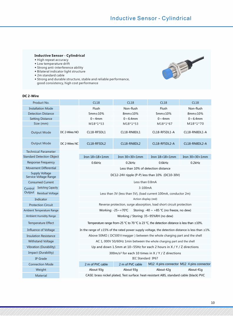
5mm±10%
0~4mm
Iron 18×18×1mm
0.6kHz
8mm±10% 5mm±10% 8mm±10%
0~6.4mm 0~4mm 0~6.4mm
Iron 30×30×1mm Iron 18×18×1mm Iron 30×30×1mm
0.2kHz 0.6kHz 0.2kHz
2 m of PVC cable 2 m of PVC cable M12 4 pins connector M12 4 pins connector
CASE: brass nickel plated, Test surface: heat-resistant ABS, standard cable (black) PVC
CL18 CL18 CL18 CL18
CL18-RF5DL1
CL18-RF5DL2
CL18-RN8DL1
CL18-RN8DL2
CL18-RF5DL1-A
CL18-RF5DL2-A
CL18-RN8DL1-A
CL18-RN8DL2-A
M18*1*53 M18*1*53 M18*1*67 M18*1*70
10
Protection Circuit
Weight
Material
Switching Capacity
Size (mm)
Connection Mode
IP Grade
Vibration (Durability)
Impact (Durability)
Withstand Voltage
Insulation Resistance
Influence of Voltage
Temperature Effect
Ambient Temperature Range
Indicator
Ambient Humidity Range
Control
Output Residual Voltage
Product No.
Installation Mode
Detection Distance
Setting Distance
Output Mode
Output Mode
Technical Parameter
Standard Detection Object
Response Frequency
Movement Differential
Supply Voltage Service Voltage Range
Consumed Current
Inductive Sensor - Cylindrical
◆ High repeat accuracy
◆ Low temperature drift
◆ Strong anti-interference ability
◆ Bilateral indicator light structure
◆ 2m standard cable
◆ Strong and durable structure, stable and reliable performance,
good consistency, high cost performance
Less than 10% of detection distance
DC12-24V ripple (P-P) less than 10% (DC10-30V)
Less than 0.8mA
3-100mA
Less than 3V (less than 5V), (load current 100mA, conductor 2m)
Action display (red)
Reverse protection, surge absorption, load short circuit protection
Working: -25~+70℃ Storing: -40 ~ +85 ℃ (no freeze, no dew)
Working / Storing: 35~95%RH (no dew)
IEC Standard IP67
About 93g About 93g About 42g About 41g
DC 2-Wire
DC 2-Wires NO
DC 2-Wires NC
Non-flushFlush Non-flush Flush
Inductive Sensor - Cylindrical
Above 50MΩ(DC500Vmegger)between the whole charging part and the shell
AC 1, 000V 50/60Hz 1min between the whole charging part and the shell
300m/s² for each 10 times in X / Y / Z directions
Up and down 1.5mm at 10~55Hz for each 2 hours in X / Y / Z directions
In the range of ±15% of the rated power supply voltage, the detection distance is less than ±1%.
Temperature range from-25 ℃ to 70 ℃ is 23 ℃, the detection distance is less than ±10%.
9
2mm±10%
0~1.6mm
Iron 12×12×1mm
1kHz
4mm±10% 2mm±10% 4mm±10%
0~3.2mm 0~1.6mm 0~3.2mm
Iron 15×15×1mm Iron 12×12×1mm Iron 15×15×1mm
0.4kHz 1kHz 0.4kHz
Less than 0.8mA
3-100mA
Less than 3V (less than 5V), (load current 100mA, conductor 2m)
Action display (red)
Reverse protection, surge absorption, load short circuit protection
Working: -25~+70℃ Storing: -40 ~ +85 ℃ (no freeze, no dew)
Working / Storing: 35~95%RH (no dew)
IEC Standard IP67
2 m of PVC cable 2 m of PVC cable M12 4 pins connector M12 4 pins connector
Case : brass nickel plated, Test surface: heat-resistant ABS, standard cable (black) PVC
CL12 CL12 CL12 CL12
CL12-RF2DL1 CL12-RN4DL1 CL12-RF2DL1-A CL12-RN4DL1-A
About54g About52g About15g About14g
CL12-RF2DL2 CL12-RN4DL2 CL12-RF2DL2-A CL12-RN4DL2-A
M12*1*42 M12*1*42 M12*1*55 M12*1*58
Inductive Sensor - Cylindrical
◆ The measurement deviation between the same type of sensor is very small
◆ Low temperature drift
◆ Strong anti-interference ability
◆ High response frequency
◆ Bilateral indicator light structure
◆ 2m standard cable
◆ Strong and durable structure, stable and reliable performance,
good consistency, high cost performance
Protection Circuit
Weight
Material
Switching Capacity
Size (mm)
Connection Mode
IP Grade
Vibration (Durability)
Impact (Durability)
Withstand Voltage
Insulation Resistance
Influence of Voltage
Temperature Effect
Ambient Temperature Range
Indicator
Ambient Humidity Range
Control
Output Residual Voltage
Product No.
Installation Mode
Detection Distance
Setting Distance
Output Mode
Output Mode
Technical Parameter
Standard Detection Object
Response Frequency
Movement Differential
Supply Voltage Service Voltage Range
Consumed Current
Less than 10% of detection distance
DC12-24V ripple (P-P) less than 10% (DC10-30V)
DC 2-Wire
DC 2-Wires NO
DC 2-Wires NC
Non-flush Non-flushFlush Flush
Above 50MΩ(DC500Vmegger)between the whole charging part and the shell
AC 1, 000V 50/60Hz 1min between the whole charging part and the shell
300m/s² for each 10 times in X / Y / Z directions
Up and down 1.5mm at 10~55Hz for each 2 hours in X / Y / Z directions
In the range of ±15% of the rated power supply voltage, the detection distance is less than ±1%.
Temperature range from-25 ℃ to 70 ℃ is 23 ℃, the detection distance is less than ±10%.
5mm±10%
0~4mm
Iron 18×18×1mm
0.6kHz
8mm±10% 5mm±10% 8mm±10%
0~6.4mm 0~4mm 0~6.4mm
Iron 30×30×1mm Iron 18×18×1mm Iron 30×30×1mm
0.2kHz 0.6kHz 0.2kHz
2 m of PVC cable 2 m of PVC cable M12 4 pins connector M12 4 pins connector
CASE: brass nickel plated, Test surface: heat-resistant ABS, standard cable (black) PVC
CL18 CL18 CL18 CL18
CL18-RF5DL1
CL18-RF5DL2
CL18-RN8DL1
CL18-RN8DL2
CL18-RF5DL1-A
CL18-RF5DL2-A
CL18-RN8DL1-A
CL18-RN8DL2-A
M18*1*53 M18*1*53 M18*1*67 M18*1*70
10
Protection Circuit
Weight
Material
Switching Capacity
Size (mm)
Connection Mode
IP Grade
Vibration (Durability)
Impact (Durability)
Withstand Voltage
Insulation Resistance
Influence of Voltage
Temperature Effect
Ambient Temperature Range
Indicator
Ambient Humidity Range
Control
Output Residual Voltage
Product No.
Installation Mode
Detection Distance
Setting Distance
Output Mode
Output Mode
Technical Parameter
Standard Detection Object
Response Frequency
Movement Differential
Supply Voltage Service Voltage Range
Consumed Current
Inductive Sensor - Cylindrical
◆ High repeat accuracy
◆ Low temperature drift
◆ Strong anti-interference ability
◆ Bilateral indicator light structure
◆ 2m standard cable
◆ Strong and durable structure, stable and reliable performance,
good consistency, high cost performance
Less than 10% of detection distance
DC12-24V ripple (P-P) less than 10% (DC10-30V)
Less than 0.8mA
3-100mA
Less than 3V (less than 5V), (load current 100mA, conductor 2m)
Action display (red)
Reverse protection, surge absorption, load short circuit protection
Working: -25~+70℃ Storing: -40 ~ +85 ℃ (no freeze, no dew)
Working / Storing: 35~95%RH (no dew)
IEC Standard IP67
About 93g About 93g About 42g About 41g
DC 2-Wire
DC 2-Wires NO
DC 2-Wires NC
Non-flushFlush Non-flush Flush
Inductive Sensor - Cylindrical
Above 50MΩ(DC500Vmegger)between the whole charging part and the shell
AC 1, 000V 50/60Hz 1min between the whole charging part and the shell
300m/s² for each 10 times in X / Y / Z directions
Up and down 1.5mm at 10~55Hz for each 2 hours in X / Y / Z directions
In the range of ±15% of the rated power supply voltage, the detection distance is less than ±1%.
Temperature range from-25 ℃ to 70 ℃ is 23 ℃, the detection distance is less than ±10%.
11
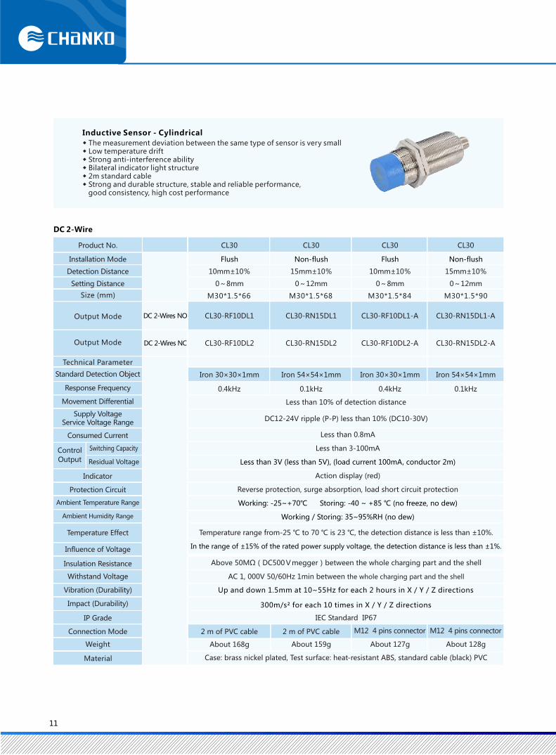
10mm±10%
0~8mm
Iron 30×30×1mm
0.4kHz
15mm±10% 10mm±10% 15mm±10%
0~12mm 0~8mm 0~12mm
Iron 54×54×1mm Iron 30×30×1mm Iron 54×54×1mm
0.1kHz 0.4kHz 0.1kHz
DC12-24V ripple (P-P) less than 10% (DC10-30V)
Less than 0.8mA
Less than 3-100mA
Less than 3V (less than 5V), (load current 100mA, conductor 2m)
Action display (red)
Reverse protection, surge absorption, load short circuit protection
Working: -25~+70℃ Storing: -40 ~ +85 ℃ (no freeze, no dew)
Working / Storing: 35~95%RH (no dew)
Temperature range from-25 ℃ to 70 ℃ is 23 ℃, the detection distance is less than ±10%.
In the range of ±15% of the rated power supply voltage, the detection distance is less than ±1%.
IEC Standard IP67
2 m of PVC cable 2 m of PVC cable M12 4 pins connector M12 4 pins connector
Case: brass nickel plated, Test surface: heat-resistant ABS, standard cable (black) PVC
CL30 CL30 CL30 CL30
CL30-RF10DL1 CL30-RN15DL1 CL30-RF10DL1-A CL30-RN15DL1-A
About 168g About 159g About 127g About 128g
CL30-RF10DL2 CL30-RN15DL2 CL30-RF10DL2-A CL30-RN15DL2-A
M30*1.5*66 M30*1.5*68 M30*1.5*84 M30*1.5*90
Less than 10% of detection distance
Protection Circuit
Weight
Material
Switching Capacity
Size (mm)
Connection Mode
IP Grade
Vibration (Durability)
Impact (Durability)
Withstand Voltage
Insulation Resistance
Influence of Voltage
Temperature Effect
Ambient Temperature Range
Indicator
Ambient Humidity Range
Control
Output Residual Voltage
Product No.
Installation Mode
Detection Distance
Setting Distance
Output Mode
Output Mode
Technical Parameter
Standard Detection Object
Response Frequency
Movement Differential
Supply Voltage Service Voltage Range
Consumed Current
DC 2-Wire
DC 2-Wires NO
DC 2-Wires NC
Non-flush Non-flushFlush Flush
Above 50MΩ(DC500Vmegger)between the whole charging part and the shell
AC 1, 000V 50/60Hz 1min between the whole charging part and the shell
Inductive Sensor - Cylindrical
◆ The measurement deviation between the same type of sensor is very small◆ Low temperature drift◆ Strong anti-interference ability◆ Bilateral indicator light structure◆ 2m standard cable◆ Strong and durable structure, stable and reliable performance, good consistency, high cost performance
300m/s² for each 10 times in X / Y / Z directions
Up and down 1.5mm at 10~55Hz for each 2 hours in X / Y / Z directions
12
2mm±10%
0~1.6mm
Iron 12×12×1mm
25Hz
4mm±10% 2mm±10% 4mm±10%
0~3.2mm 0~1.6mm 0~3.2mm
Less than 10% of detection distance
Iron 15×15×1mm Iron 12×12×1mm Iron 15×15×1mm
25Hz 25Hz 25Hz
AC24~240V 50/60Hz (AC20~264V)
Less than 1.7mA
Action display (red)
Surge absorption
IEC Standard IP67
2 m of PVC cable
About 54g
2 m of PVC cable
About 52g
M12 4 pins connector
About 15g
M12 4 pins connector
About 14g
Case: brass nickel plated, Test surface: heat-resistant ABS, standard cable
CL12 CL12 CL12 CL12
CL12-RF2AK1
CL12-RF2AK2
CL12-RN4AK1
CL12-RN4AK2
CL12-RF2AK1-A
CL12-RF2AK2-A
CL12-RN4AK1-A
CL12-RN4AK2-A
5-200mA
M12*1*42 M12*1*55 M12*1*58M12*1*42
Inductive Sensor - Cylindrical
◆ The measurement deviation between the same type of sensor is very small
◆ Low temperature drift
◆ Strong anti-interference ability
◆ Bilateral indicator light structure
◆ 2m standard cable
◆ Strong and durable structure, stable and reliable performance,
good consistency, high cost performance
AC 2-Wire
Size (mm)
Product No.
Installation Mode
Detection Distance
Setting Distance
Output Mode
Output Mode
Technical Parameter
Standard Detection Object
Response Frequency
Movement Differential
Supply Voltage Service Voltage Range
Consumed Current
Switching Capacity
Indicator
Protection Circuit
Ambient Temperature Range
Ambient Humidity Range
Temperature Effect
Influence of Voltage
Insulation Resistance
Withstand Voltage
Vibration (Durability)
Impact (Durability)
IP Grade
Connection Mode
Weight
Material
AC 2-Wires NO
AC 2-Wires NC
Non-flushFlush Non-flush Flush
Working: -25~+70℃ Storing: -40 ~ +85 ℃ (no freeze, no dew)
Working / Storing: 35~95%RH (no dew)
Above 50MΩ(DC500Vmegger)between the whole charging part and the shell
AC 1, 000V 50/60Hz 1min between the whole charging part and the shell
Inductive Sensor - Cylindrical
300m/s² for each 10 times in X / Y / Z directions
Up and down 1.5mm at 10~55Hz for each 2 hours in X / Y / Z directions
In the range of ±15% of the rated power supply voltage, the detection distance is less than ±1%.
Temperature range from-25 ℃ to 70 ℃ is 23 ℃, the detection distance is less than ±10%.

11
10mm±10%
0~8mm
Iron 30×30×1mm
0.4kHz
15mm±10% 10mm±10% 15mm±10%
0~12mm 0~8mm 0~12mm
Iron 54×54×1mm Iron 30×30×1mm Iron 54×54×1mm
0.1kHz 0.4kHz 0.1kHz
DC12-24V ripple (P-P) less than 10% (DC10-30V)
Less than 0.8mA
Less than 3-100mA
Less than 3V (less than 5V), (load current 100mA, conductor 2m)
Action display (red)
Reverse protection, surge absorption, load short circuit protection
Working: -25~+70℃ Storing: -40 ~ +85 ℃ (no freeze, no dew)
Working / Storing: 35~95%RH (no dew)
Temperature range from-25 ℃ to 70 ℃ is 23 ℃, the detection distance is less than ±10%.
In the range of ±15% of the rated power supply voltage, the detection distance is less than ±1%.
IEC Standard IP67
2 m of PVC cable 2 m of PVC cable M12 4 pins connector M12 4 pins connector
Case: brass nickel plated, Test surface: heat-resistant ABS, standard cable (black) PVC
CL30 CL30 CL30 CL30
CL30-RF10DL1 CL30-RN15DL1 CL30-RF10DL1-A CL30-RN15DL1-A
About 168g About 159g About 127g About 128g
CL30-RF10DL2 CL30-RN15DL2 CL30-RF10DL2-A CL30-RN15DL2-A
M30*1.5*66 M30*1.5*68 M30*1.5*84 M30*1.5*90
Less than 10% of detection distance
Protection Circuit
Weight
Material
Switching Capacity
Size (mm)
Connection Mode
IP Grade
Vibration (Durability)
Impact (Durability)
Withstand Voltage
Insulation Resistance
Influence of Voltage
Temperature Effect
Ambient Temperature Range
Indicator
Ambient Humidity Range
Control
Output Residual Voltage
Product No.
Installation Mode
Detection Distance
Setting Distance
Output Mode
Output Mode
Technical Parameter
Standard Detection Object
Response Frequency
Movement Differential
Supply Voltage Service Voltage Range
Consumed Current
DC 2-Wire
DC 2-Wires NO
DC 2-Wires NC
Non-flush Non-flushFlush Flush
Above 50MΩ(DC500Vmegger)between the whole charging part and the shell
AC 1, 000V 50/60Hz 1min between the whole charging part and the shell
Inductive Sensor - Cylindrical
◆ The measurement deviation between the same type of sensor is very small◆ Low temperature drift◆ Strong anti-interference ability◆ Bilateral indicator light structure◆ 2m standard cable◆ Strong and durable structure, stable and reliable performance, good consistency, high cost performance
300m/s² for each 10 times in X / Y / Z directions
Up and down 1.5mm at 10~55Hz for each 2 hours in X / Y / Z directions
12
2mm±10%
0~1.6mm
Iron 12×12×1mm
25Hz
4mm±10% 2mm±10% 4mm±10%
0~3.2mm 0~1.6mm 0~3.2mm
Less than 10% of detection distance
Iron 15×15×1mm Iron 12×12×1mm Iron 15×15×1mm
25Hz 25Hz 25Hz
AC24~240V 50/60Hz (AC20~264V)
Less than 1.7mA
Action display (red)
Surge absorption
IEC Standard IP67
2 m of PVC cable
About 54g
2 m of PVC cable
About 52g
M12 4 pins connector
About 15g
M12 4 pins connector
About 14g
Case: brass nickel plated, Test surface: heat-resistant ABS, standard cable
CL12 CL12 CL12 CL12
CL12-RF2AK1
CL12-RF2AK2
CL12-RN4AK1
CL12-RN4AK2
CL12-RF2AK1-A
CL12-RF2AK2-A
CL12-RN4AK1-A
CL12-RN4AK2-A
5-200mA
M12*1*42 M12*1*55 M12*1*58M12*1*42
Inductive Sensor - Cylindrical
◆ The measurement deviation between the same type of sensor is very small
◆ Low temperature drift
◆ Strong anti-interference ability
◆ Bilateral indicator light structure
◆ 2m standard cable
◆ Strong and durable structure, stable and reliable performance,
good consistency, high cost performance
AC 2-Wire
Size (mm)
Product No.
Installation Mode
Detection Distance
Setting Distance
Output Mode
Output Mode
Technical Parameter
Standard Detection Object
Response Frequency
Movement Differential
Supply Voltage Service Voltage Range
Consumed Current
Switching Capacity
Indicator
Protection Circuit
Ambient Temperature Range
Ambient Humidity Range
Temperature Effect
Influence of Voltage
Insulation Resistance
Withstand Voltage
Vibration (Durability)
Impact (Durability)
IP Grade
Connection Mode
Weight
Material
AC 2-Wires NO
AC 2-Wires NC
Non-flushFlush Non-flush Flush
Working: -25~+70℃ Storing: -40 ~ +85 ℃ (no freeze, no dew)
Working / Storing: 35~95%RH (no dew)
Above 50MΩ(DC500Vmegger)between the whole charging part and the shell
AC 1, 000V 50/60Hz 1min between the whole charging part and the shell
Inductive Sensor - Cylindrical
300m/s² for each 10 times in X / Y / Z directions
Up and down 1.5mm at 10~55Hz for each 2 hours in X / Y / Z directions
In the range of ±15% of the rated power supply voltage, the detection distance is less than ±1%.
Temperature range from-25 ℃ to 70 ℃ is 23 ℃, the detection distance is less than ±10%.

13
Iron 18×18×1mm
25Hz
Less than 10% of detection distance
Iron 30×30×1mm Iron 18×18×1mm Iron 30×30×1mm
25Hz 25Hz 25Hz
CL18-RF5AK1 CL18-RN8AK1 CL18-RF5AK1-A CL18-RN8AK1-A
CL18-RF5AK2 CL18-RN8AK2 CL18-RF5AK2-A CL18-RN8AK2-A
IEC Standard IP67
AC24-240V 50/60Hz (AC20-264V)
Less than 1.7mA
Temperature range from-25 ℃ to 70 ℃ is 23 ℃, the detection distance is less than ±10%.
2 m of PVC cable 2 m of PVC cable
About 93g About 93g
Case: brass nickel plated, Test surface: heat-resistant ABS, standard cable
5-200mA
5mm±10%
0~4mm
8mm±10% 5mm±10% 8mm±10%
0~6.4mm 0~4mm 0~6.4mm
CL18 CL18 CL18 CL18
M18*1*53 M18*1*53 M18*1*67 M18*1*70
AC 2-Wire
Action display (red)
Surge absorption
Size (mm)
Product No.
Installation Mode
Detection Distance
Setting Distance
Output Mode
Output Mode
Technical Parameter
Standard Detection Object
Response Frequency
Movement Differential
Supply Voltage Service Voltage Range
Switching Capacity
Indicator
Protection Circuit
Ambient Temperature Range
Ambient Humidity Range
Temperature Effect
Influence of Voltage
Insulation Resistance
Withstand Voltage
Vibration (Durability)
Impact (Durability)
IP Grade
Connection Mode
Weight
Material
M12 4 pins connector
About 42g
M12 4 pins connector
About 41g
AC 2-Wires NO
AC 2-Wires NC
Non-flush Non-flushFlush Flush
Working: -25~+70℃ Storing: -40 ~ +85 ℃ (no freeze, no dew)
Working / Storing: 35~95%RH (no dew)
Consumed Current
Above 50MΩ(DC500Vmegger)between the whole charging part and the shell
AC 1, 000V 50/60Hz 1min between the whole charging part and the shell
Inductive Sensor - Cylindrical
◆ High repeat accuracy
◆ Low temperature drift
◆ Strong anti-interference ability
◆ Bilateral indicator light structure
◆ 2m standard cable
◆ Strong and durable structure, stable and reliable performance,
good consistency, high cost performance
300m/s² for each 10 times in X / Y / Z directions
Up and down 1.5mm at 10~55Hz for each 2 hours in X / Y / Z directions
In the range of ±15% of the rated power supply voltage, the detection distance is less than ±1%.
14
10mm±10%
0~8mm
Iron 30×30×1mm
25Hz
15mm±10% 10mm±10% 15mm±10%
0~12mm 0~8mm 0~12mm
Less than 10% of detection distance
Iron 54×54×1mm Iron 30×30×1mm Iron 54×54×1mm
25Hz 25Hz 25Hz
AC24-240V 50/60Hz (AC20-264V)
Less than 1.7mA
Temperature range from-25 ℃ to 70 ℃ is 23 ℃, the detection distance is less than ±10%.
IEC Standard IP67
2 m of PVC cable 2 m of PVC cable M12 4 pins connector M12 4 pins connector
Case: nickel-plated brass, Test surface: heat-resistant ABS, standard cable (black) PVC
CL30 CL30 CL30 CL30
CL30-RF10AK1
CL30-RF10AK2
CL30-RN15AK1
CL30-RN15AK2
CL30-RF10AK1-A
CL30-RF10AK2-A
CL30-RN15AK1-A
CL30-RN15AK2-A
5-200mA
M30*1.5*66 M30*1.5*68 M30*1.5*84 M30*1.5*90
Inductive Sensor - Cylindrical
◆ The measurement deviation between the same type of sensor is very small
◆ Low temperature drift
◆ Strong anti-interference ability
◆ Bilateral indicator light structure
◆ 2m standard cable
◆ Strong and durable structure, stable and reliable performance,
good consistency, high cost performance
Action display (red)
Surge absorption
AC 2-Wire
Size (mm)
Product No.
Installation Mode
Detection Distance
Setting Distance
Output Mode
Output Mode
Technical Parameter
Standard Detection Object
Response Frequency
Movement Differential
Supply Voltage Service Voltage Range
Consumed Current
Switching Capacity
Indicator
Protection Circuit
Ambient Temperature Range
Ambient Humidity Range
Temperature Effect
Influence of Voltage
Insulation Resistance
Withstand Voltage
Vibration (Durability)
Impact (Durability)
IP Grade
Connection Mode
Weight
Material
About 168g About 159g About 127g About 128g
AC 2-Wires NO
AC 2-Wires NC
Non-flushFlush Non-flush Flush
Working: -25~+70℃ Storing: -40 ~ +85 ℃ (no freeze, no dew)
Working / Storing: 35~95%RH (no dew)
Above 50MΩ(DC500Vmegger)between the whole charging part and the shell
AC 1, 000V 50/60Hz 1min between the whole charging part and the shell
Inductive Sensor - Cylindrical
300m/s² for each 10 times in X / Y / Z directions
Up and down 1.5mm at 10~55Hz for each 2 hours in X / Y / Z directions
In the range of ±15% of the rated power supply voltage, the detection distance is less than ±1%.
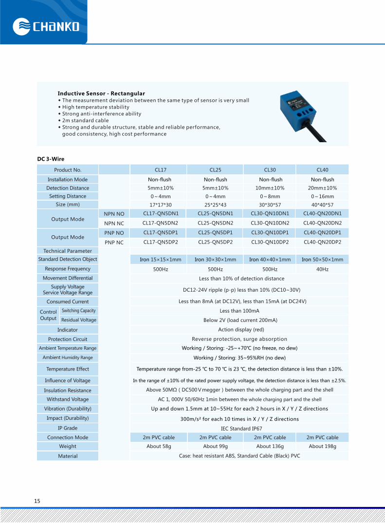
5mm±10%
0~4mm
Iron 15×15×1mm
500Hz
5mm±10% 10mm±10% 20mm±10%
0~4mm 0~8mm 0~16mm
Less than 10% of detection distance
Iron 30×30×1mm Iron 40×40×1mm Iron 50×50×1mm
500Hz 500Hz 40Hz
DC12-24V ripple (p-p) less than 10% (DC10~30V)
Less than 8mA (at DC12V), less than 15mA (at DC24V)
IEC Standard IP67
2m PVC cable 2m PVC cable 2m PVC cable 2m PVC cable
About 58g About 99g About 136g About 198g
Case: heat resistant ABS, Standard Cable (Black) PVC
CL17 CL25 CL30 CL40
Less than 100mA
Below 2V (load current 200mA)
Action display (red)
Reverse protection, surge absorption
17*17*30 25*25*43 30*30*57 40*40*57
NPN NO
NPN NC
CL17-QN5DN1 CL25-QN5DN1
CL17-QN5DN2 CL25-QN5DN2
CL30-QN10DN1
CL30-QN10DN2
CL40-QN20DN1
CL40-QN20DN2
PNP NO
PNP NC
CL17-QN5DP1
CL17-QN5DP2
CL25-QN5DP1
CL25-QN5DP2
CL30-QN10DP1
CL30-QN10DP2
CL40-QN20DP1
CL40-QN20DP2
15
DC 3-Wire
Protection Circuit
Weight
Material
Switching Capacity
Size (mm)
Connection Mode
IP Grade
Vibration (Durability)
Impact (Durability)
Withstand Voltage
Insulation Resistance
Influence of Voltage
Temperature Effect
Ambient Temperature Range
Indicator
Ambient Humidity Range
Control
Output Residual Voltage
Product No.
Installation Mode
Detection Distance
Setting Distance
Output Mode
Output Mode
Technical Parameter
Standard Detection Object
Response Frequency
Movement Differential
Supply Voltage Service Voltage Range
Consumed Current
Non-flush Non-flush Non-flush Non-flush
Working / Storing: -25~+70℃ (no freeze, no dew)
Working / Storing: 35~95%RH (no dew)
Above 50MΩ(DC500Vmegger)between the whole charging part and the shell
AC 1, 000V 50/60Hz 1min between the whole charging part and the shell
◆ The measurement deviation between the same type of sensor is very small
◆ High temperature stability
◆ Strong anti-interference ability
◆ 2m standard cable
◆ Strong and durable structure, stable and reliable performance,
good consistency, high cost performance
Inductive Sensor - Rectangular
300m/s² for each 10 times in X / Y / Z directions
Up and down 1.5mm at 10~55Hz for each 2 hours in X / Y / Z directions
Temperature range from-25 ℃ to 70 ℃ is 23 ℃, the detection distance is less than ±10%.
In the range of ±10% of the rated power supply voltage, the detection distance is less than ±2.5%.
16
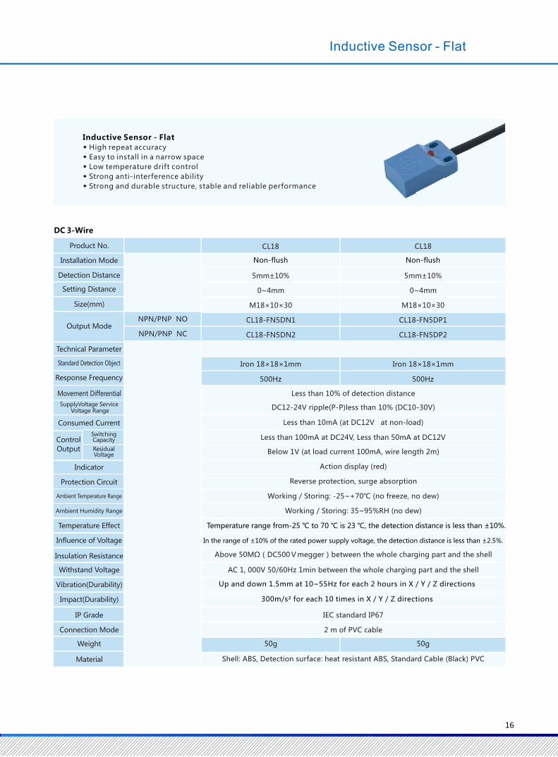
NPN/PNP N0
NPN/PNP NC
CL18
Non-flush
5mm±10%
0~4mm
M18×10×30
CL18-FN5DN1
CL18-FN5DN2
CL18
Non-flush
5mm±10%
0~4mm
M18×10×30
CL18-FN5DP1
CL18-FN5DP2
Iron 18×18×1mm Iron 18×18×1mm
500Hz 500Hz
50g 50g
NPN/PNP NO
NPN/PNP NC
◆ High repeat accuracy
◆ Easy to install in a narrow space
◆ Low temperature drift control
◆ Strong anti-interference ability
◆ Strong and durable structure, stable and reliable performance
Inductive Sensor - Flat
Consumed Current Control
Output
Switching Capacity
ResidualVoltage
Indicator
Protection Circuit
Ambient Temperature Range
Ambient Humidity Range
Temperature Effect
Influence of Voltage
Insulation Resistance
Withstand Voltage
Vibration(Durability)
Impact(Durability)
IP Grade
Connection Mode
Weight
Material
Product No.
Installation Mode
Detection Distance
Setting Distance
Size(mm)
Output Mode
Technical Parameter
Standard Detection Object
Response Frequency
Movement Differential
SupplyVoltage Service Voltage Range
Less than 10% of detection distance
DC12-24V ripple(P-P)less than 10% (DC10-30V)
Less than 10mA (at DC12V at non-load)
Less than 100mA at DC24V, Less than 50mA at DC12V
Below 1V (at load current 100mA, wire length 2m)
Action display (red)
Reverse protection, surge absorption
Working / Storing: -25~+70℃ (no freeze, no dew)
Working / Storing: 35~95%RH (no dew)
AC 1, 000V 50/60Hz 1min between the whole charging part and the shell
IEC standard IP67
2 m of PVC cable
Shell: ABS, Detection surface: heat resistant ABS, Standard Cable (Black) PVC
Above 50MΩ(DC500Vmegger)between the whole charging part and the shell
Inductive Sensor - Flat
DC 3-Wire
300m/s² for each 10 times in X / Y / Z directions
Up and down 1.5mm at 10~55Hz for each 2 hours in X / Y / Z directions
Temperature range from-25 ℃ to 70 ℃ is 23 ℃, the detection distance is less than ±10%.
In the range of ±10% of the rated power supply voltage, the detection distance is less than ±2.5%.
5mm±10%
0~4mm
Iron 15×15×1mm
500Hz
5mm±10% 10mm±10% 20mm±10%
0~4mm 0~8mm 0~16mm
Less than 10% of detection distance
Iron 30×30×1mm Iron 40×40×1mm Iron 50×50×1mm
500Hz 500Hz 40Hz
DC12-24V ripple (p-p) less than 10% (DC10~30V)
Less than 8mA (at DC12V), less than 15mA (at DC24V)
IEC Standard IP67
2m PVC cable 2m PVC cable 2m PVC cable 2m PVC cable
About 58g About 99g About 136g About 198g
Case: heat resistant ABS, Standard Cable (Black) PVC
CL17 CL25 CL30 CL40
Less than 100mA
Below 2V (load current 200mA)
Action display (red)
Reverse protection, surge absorption
17*17*30 25*25*43 30*30*57 40*40*57
NPN NO
NPN NC
CL17-QN5DN1 CL25-QN5DN1
CL17-QN5DN2 CL25-QN5DN2
CL30-QN10DN1
CL30-QN10DN2
CL40-QN20DN1
CL40-QN20DN2
PNP NO
PNP NC
CL17-QN5DP1
CL17-QN5DP2
CL25-QN5DP1
CL25-QN5DP2
CL30-QN10DP1
CL30-QN10DP2
CL40-QN20DP1
CL40-QN20DP2
15
DC 3-Wire
Protection Circuit
Weight
Material
Switching Capacity
Size (mm)
Connection Mode
IP Grade
Vibration (Durability)
Impact (Durability)
Withstand Voltage
Insulation Resistance
Influence of Voltage
Temperature Effect
Ambient Temperature Range
Indicator
Ambient Humidity Range
Control
Output Residual Voltage
Product No.
Installation Mode
Detection Distance
Setting Distance
Output Mode
Output Mode
Technical Parameter
Standard Detection Object
Response Frequency
Movement Differential
Supply Voltage Service Voltage Range
Consumed Current
Non-flush Non-flush Non-flush Non-flush
Working / Storing: -25~+70℃ (no freeze, no dew)
Working / Storing: 35~95%RH (no dew)
Above 50MΩ(DC500Vmegger)between the whole charging part and the shell
AC 1, 000V 50/60Hz 1min between the whole charging part and the shell
◆ The measurement deviation between the same type of sensor is very small
◆ High temperature stability
◆ Strong anti-interference ability
◆ 2m standard cable
◆ Strong and durable structure, stable and reliable performance,
good consistency, high cost performance
Inductive Sensor - Rectangular
300m/s² for each 10 times in X / Y / Z directions
Up and down 1.5mm at 10~55Hz for each 2 hours in X / Y / Z directions
Temperature range from-25 ℃ to 70 ℃ is 23 ℃, the detection distance is less than ±10%.
In the range of ±10% of the rated power supply voltage, the detection distance is less than ±2.5%.
16
NPN/PNP N0
NPN/PNP NC
CL18
Non-flush
5mm±10%
0~4mm
M18×10×30
CL18-FN5DN1
CL18-FN5DN2
CL18
Non-flush
5mm±10%
0~4mm
M18×10×30
CL18-FN5DP1
CL18-FN5DP2
Iron 18×18×1mm Iron 18×18×1mm
500Hz 500Hz
50g 50g
NPN/PNP NO
NPN/PNP NC
◆ High repeat accuracy
◆ Easy to install in a narrow space
◆ Low temperature drift control
◆ Strong anti-interference ability
◆ Strong and durable structure, stable and reliable performance
Inductive Sensor - Flat
Consumed Current Control
Output
Switching Capacity
ResidualVoltage
Indicator
Protection Circuit
Ambient Temperature Range
Ambient Humidity Range
Temperature Effect
Influence of Voltage
Insulation Resistance
Withstand Voltage
Vibration(Durability)
Impact(Durability)
IP Grade
Connection Mode
Weight
Material
Product No.
Installation Mode
Detection Distance
Setting Distance
Size(mm)
Output Mode
Technical Parameter
Standard Detection Object
Response Frequency
Movement Differential
SupplyVoltage Service Voltage Range
Less than 10% of detection distance
DC12-24V ripple(P-P)less than 10% (DC10-30V)
Less than 10mA (at DC12V at non-load)
Less than 100mA at DC24V, Less than 50mA at DC12V
Below 1V (at load current 100mA, wire length 2m)
Action display (red)
Reverse protection, surge absorption
Working / Storing: -25~+70℃ (no freeze, no dew)
Working / Storing: 35~95%RH (no dew)
AC 1, 000V 50/60Hz 1min between the whole charging part and the shell
IEC standard IP67
2 m of PVC cable
Shell: ABS, Detection surface: heat resistant ABS, Standard Cable (Black) PVC
Above 50MΩ(DC500Vmegger)between the whole charging part and the shell
Inductive Sensor - Flat
DC 3-Wire
300m/s² for each 10 times in X / Y / Z directions
Up and down 1.5mm at 10~55Hz for each 2 hours in X / Y / Z directions
Temperature range from-25 ℃ to 70 ℃ is 23 ℃, the detection distance is less than ±10%.
In the range of ±10% of the rated power supply voltage, the detection distance is less than ±2.5%.
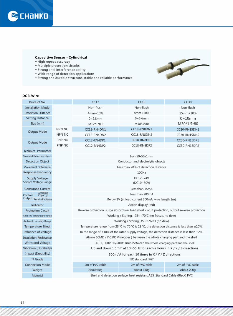
DC 3-Wire
NPN NO
NPN NC
PNP NO
PNP NC
CC12
4mm+10%
0~2.8mm
M12*1*80
CC12-RN4DN1
CC12-RN4DN2
CC12-RN4DP1
CC12-RN4DP2
8mm+10%
0~5.6mm
M18*1*80
CC18-RN8DN1
CC18-RN8DN2
CC18-RN8DP1
CC18-RN8DP2
15mm+10%
0~10mm
M30*1.5*80
CC30-RN15DN1
CC30-RN15DN2
CC30-RN15DP1
CC30-RN15DP2
CC18 CC30
◆ High repeat accuracy
◆ Multiple protection circuits
◆ Strong anti-interference ability
◆ Wide range of detection applications
◆ Strong and durable structure, stable and reliable performance
Capacitive Sensor - Cylindrical
Product No.
Installation Mode
Detection Distance
Setting Distance
Size (mm)
Output Mode
Output Mode
Technical Parameter
Standard Detection Object
Detection Object
Movement Differential
Response Frequency
Supply Voltage
Service Voltage Range
Consumed Current
ControlOutput
SwitchingCapacity
Residual Voltage
Indicator
Protection Circuit
Ambient Temperature Range
Ambient Humidity Range
Temperature Effect
Influence of Voltage
Insulation Resistance
Withstand Voltage
Vibration (Durability)
Impact (Durability)
IP Grade
Connection Mode
Weight
Material
Non-flush Non-flush Non-flush
Iron 50x50x1mm
Conductor and electrolytic objects
Less than 20% of detection distance
100Hz
DC12~24V
(DC10~30V)
Less than 15mA
Less than 200mA
Below 2V (at load current 200mA, wire length 2m)
Action display (red)
Reverse protection, surge absorption, load short circuit protection, output reverse protection
Working / Storing: -25~+70℃ (no freeze, no dew)
Working / Storing: 35~95%RH (no dew)
Temperature range from-25 ℃ to 70 ℃ is 23 ℃, the detection distance is less than ±20%.
In the range of ±10% of the rated supply voltage, the detection distance is less than ±2%.
Above 50MΩ(DC500Vmegger)between the whole charging part and the shell
IEC standard IP67
2m of PVC cable 2m of PVC cable 2m of PVC cable
About 60g About 140g About 200g
Shell and detection surface: heat resistant ABS, Standard Cable (Black) PVC
17
300m/s² for each 10 times in X / Y / Z directions
Up and down 1.5mm at 10~55Hz for each 2 hours in X / Y / Z directions
AC 1, 000V 50/60Hz 1min between the whole charging part and the shell
AC 2-Wire NO
AC 2-Wire NC
CC12
4mm+10%
0~2.8mm
M12*1*80
CC12-RN4AK1
CC12-RN4AK2
CC18
8mm+10%
0~5.6mm
M12*1*80
CC18-RN8AK1
CC18-RN8AK2
CC30
15mm+10%
0~10mm
M30*1.5*80
CC30-RN15AK1
CC30-RN15AK2
AC 2-Wire
◆ High repeat accuracy
◆ Multiple protection circuits
◆ Strong anti-interference ability
◆ Wide range of detection applications
◆ Strong and durable structure, stable and reliable performance
Capacitive Sensor - Cylindrical
Product No.
Installation Mode
Detection Distance
Setting Distance
Size (mm)
Output Mode
Technical Parameter
Standard Detection Object
Detection Object
Movement Differential
Response Frequency
Supply Voltage
Service Voltage Range
Consumed Current
Switching Capacity
Residual Voltage
Indicator
Protection Circuit
Ambient Temperature Range
Ambient Humidity Range
Temperature Effect
Influence of Voltage
Insulation Resistance
Withstand Voltage
Vibration (Durability)
Impact (Durability)
IP Grade
Connection Mode
Weight
Material
ControlOutput
Non-flush Non-flush Non-flush
Iron 50x50x1mm
Conductor and electrolytic objects
Less than 20% of detection distance
100Hz
AC100~220V
(AC90~250V)
Less than 2.2mA
Less than 10~200mA
Less than 20V
Action display (red)
Surge absorption
Working / Storing: -25~+70℃ (no freeze, no dew)
Working / Storing: 35~95%RH (no dew)
Temperature range from-25 ℃ to 70 ℃ is 23 ℃, the detection distance is less than ±20%.
In the range of ±10% of the rated supply voltage, the detection distance is less than ±2%.
Above 50MΩ(DC500Vmegger)between the whole charging part and the shell
AC 1, 000V 50/60Hz 1min between the whole charging part and the shell
IEC standard IP67
2m of PVC cable 2m of PVC cable 2m of PVC cable
About 60g About 140g About 200g
Shell and detection surface: heat resistant ABS, Standard Cable (Black) PVC
18
Capacitive Sensor - Cylindrical
300m/s² for each 10 times in X / Y / Z directions
Up and down 1.5mm at 10~55Hz for each 2 hours in X / Y / Z directions
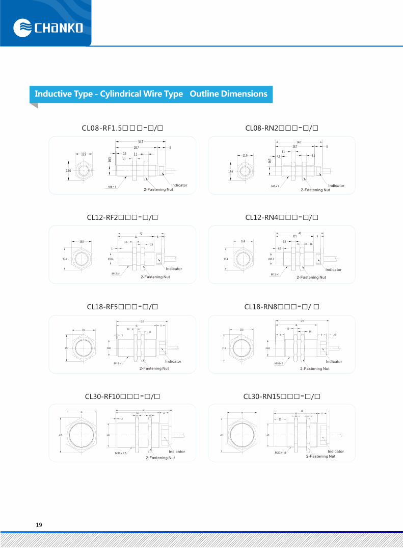
Inductive Type - Cylindrical Wire Type Outline Dimensions
CL08-RN2□□□-□/□CL08-RF1.5□□□-□/□
CL12-RF2□□□-□/□ CL12-RN4□□□-□/□
CL18-RF5□□□-□/□ CL18-RN8□□□-□/ □
CL30-RF10□□□-□/□ CL30-RN15□□□-□/□
Indicator 2-Fastening Nut
Indicator 2-Fastening Nut
Indicator
2-Fastening Nut
Indicator
2-Fastening Nut
2-Fastening Nut
Indicator
2-Fastening Nut
Indicator
2-Fastening Nut
Indicator
2-Fastening Nut
Indicator
19
M8×1
M12×1
M18×1
M30×1.5 M30×1.5
M18×1
M12×1
M8×1
CL08-RF1.5□□□-□/□ CL08-RN2□□□-□/□
CL12-RF2□□□-□/□ CL12-RN4□□□-□/□
CL18-RF5□□□-□/□ CL18-RN8□□□-□/□
CL30-RF10□□□-□/□ CL30-RN15□□□-□/□
3
50
5
33
3.1
11.9
50.6
33.6
0.6 3.1
3
11.9
16.8
6.5
56.5
38.5
3.6
8
16.8
54
0.8 3.6
36 8
23.8
9.13.6
57.1
69.66.5
23.8
1
53
3.6
65.56.5
36
15
754.4
88.5
6.5
1.2 4.468.2
81.76.5
36
2-Fastening Nut 2-Fastening Nut
2-Fastening Nut 2-Fastening Nut
2-Fastening Nut 2-Fastening Nut
2-Fastening Nut 2-Fastening Nut
20
Inductive Type - Cylindrical Connector Type Outline Dimensions
M8×1 M8×1
M12×1M12×1
M18×1 M18×1
M12×1M12×1
M30×1.5
M12×1
M30×1.5
M12×1
Inductive Type - Cylindrical Connector Type Outline Dimensions
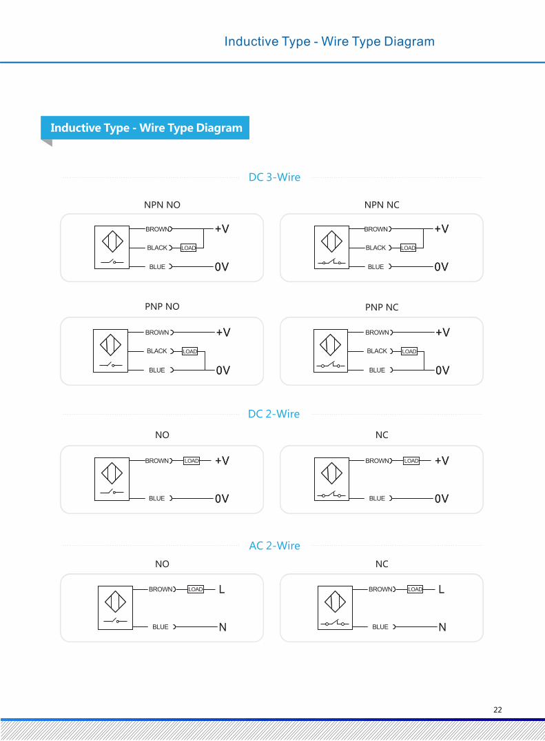
NPN NO
NO NC
NPN NC
PNP NO PNP NC
NO NC
Inductive Type - Wire Type Diagram
DC 3-Wire
DC 2-Wire
AC 2-Wire
BROWN
BLACK
BLUE
BROWN
BLACK
BLUE
LOADLOAD
BROWN
BLACK
BLUE
LOAD LOAD
BROWN
BLACK
BLUE
BROWN
BLUE
LOAD BROWN
BLUE
LOAD
LOADBROWN
BLUE
LOADBROWN
BLUE
Inductive Type - Wire Type Diagram
22
Inductive Type - Rectangular Wire Type Outline Dimensions
CL17-QN5□□□-□/□
CL30-QN10□□□-□/□ CL40-QN20□□□-□/□
CL25-QN5□□□-□/□
34
24.8
17.75.6
4.3
Φ8.9 18
2-Φ4.5(orM4)
1817
3.5
16
3028
2-Φ3.5
Φ7.5 10.5 10.5
2-Φ3.5
Rubber Sheath
Indicator
MachiningDimensions of Installation Holes
Conductor
MachiningDimensions of Installation Holes
IndicatorConductor
MachiningDimensions of Installation Holes
IndicatorConductor
2-Φ4.5(orM4)
MachiningDimensions of Installation Holes
IndicatorConductor
2-Φ4.5(orM4)
21
CC12-RN4□□/□ CC18-RN8□□/□ CC30-RN15□□/□
30.4
10.67.6 8.818
17.9 4.6
4.8
12.5
DetectionSurface
3.3
20
60
80
φ10.717
4 4 20
60
φ16.6
4 4
80
24
10
60
φ28.1
5 5
80
36
Indicator
2-Fastening Nut 2-Fastening Nut 2-Fastening Nut
Inductive Type - Flat Wire Type Outline Dimensions
Capacitive Type - Cylindrical Wire Type Outline Dimensions
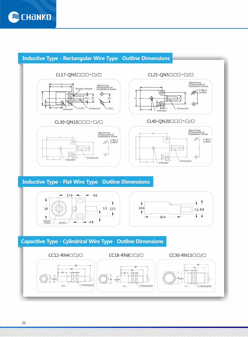

NPN NO
DC 3-Wire (4 Pins)
Inductive Type - Connector Type Diagram
BROWN
LOAD
+V
0V
2 1
3 4
+V
0V
2 1
3 4
PNP NO
BLACK
BLUE
BROWN
BLACK
BLUE
LOAD
NO
DC 2-Wire
2 1
3 4
+V
0V
2 1
3 4
+V
0V
NC
LOAD LOADBROWN
BLUE
BROWN
BLUE
AC 2-Wire
2 1
3 4
~
2 1
3 4
~
NO NC
LOADLOAD
BROWN
BLUE
BROWN
BLUE
DC 3-Wire (3 Pins)
4
13 +V
0V
4
13 +V
0V
NPN PNP
BROWN
BLACK
BLUE
BROWN
BLACK
BLUE
LOADLOAD
23 24
NPN PNP
Inductive Type - Rectangular / Flat Diagram
NPN (NO) PNP (NO)
NPN (NC) PNP (NC)
BROWN
BLACK
BLUE
BROWN
BLACK
BLUE
LOAD LOAD
Capacitive Type - Wire Type Diagram
BROWN
BLACK
BLUE
LOAD
BROWN
BLACK
BLUE
LOAD
BROWN
BLACK
BLUE
LOAD LOAD
BROWN
BLACK
BLUE
Inductive Type - Rectangular / Flat Diagram

Installation Mode of Flush Type Sensor
When the inductive sensor (proximity switch) detection
surface and the metal surface are mounted flush, other
surfaces are submerged in the metal surface and are
not affected by the metal object. Please refer to
Installation Mode of Non-Flush Type Sensor
The non-embedded inductive sensor (proximity switch)
cannot be submerged in the metal surface around the
sensor surface, and it is easy to be affected by the metal
surface. The detection distance of the non-submerged
inductive sensor is longer, and the distance between the
sides of the inductive sensor must be 3 times as long as that
of the detection head during installation to prevent
interference by metal objects.
3d<d
d
Installation Mode of Side-by-Side Sensor
When multiple inductive sensors (proximity switches) are required to be installed side by side, in order to prevent
interference between proximity switches, please refer to the chart less than to reserve a distance.
Flush :
Detection surface
d 2d≤d
d 3d≤d d
Product Installation Mode
installation surface
installation surface
Non-Flush :
25
The effect of the material close to the detected object on the measuring distance
When detecting objects of different materials, the detection distance of the proximity
switch has a corresponding change.
0%
20%
40%
60%
80%
100%
120%
Detection Distance
IP Grade Description
The second digit is the protection of water intrusion.
The first digit is the protection of solid foreign bodies.
IP
The first digit represents the level of protection (dust)
Prevent solid invasion of products with diameters
greater than 1.0mm
Prevent dust from operating site
Prevent all dust from invading
4
5
6
4
5
6
7
8
IP67
Grade
Standard
Jargon Instruction
iron stainless steel brass aluminum copperMaterial
The second digit indicates the IP Grade
Not affected by droplets splashing in any direction
Not affected by water injection in any direction
Not intruded by water spraying in any direction
No effect on invasion of water under specified time and pressure
Can still be used in water under specific pressure
26
Product Installation Mode
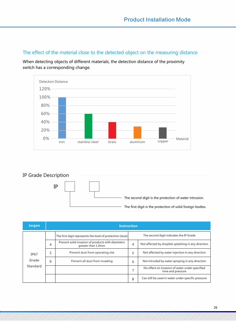

Our products are widely used in food packaging, transportation equipment, textile machinery,
semiconductor, printing machinery, pharmaceutical machinery, logistics industry, medical devices,
elevators and so on.
Product Application Case
金属瓶盖
Detection of bottle caps
Panel count
Manipulator application
Test the product for changes
Mold positioning detection
Location detection
Test screw height
Equipment production line application
27
Overview
Photoelectric sensor is a sensor which uses photoelectric element as detection element. It first converts the measured
change into the change of optical signal, and then further converts the optical signal into electrical signal with the help
of photoelectric element. Photoelectric sensor is generally composed of light source, optical path and photoelectric
element.
Series of Photoelectric Sensors
Functional Classification of Photoelectric Sensors
According to different detection methods, photoelectric sensors can be divided into three types: contrast type, the diffuse
type and the specular type.
① Through Beam Photoelectric Sensor
The photophore and the receiver are installed on the same optical axis.
When there is an object between them, the object will be detected and
output according to the change of light transmission. This kind of sensor is
called the photoelectric sensor.
② Diffuse Reflection Photoelectric Sensor
The light transmitter and receiver are photoelectric sensor. The light
transmitter sends out light to the detecting object, after the detected object
is reflected to the receiver, the light intensity of the reflected light is
recognized and detected and the output of the object is detected.
③ Mirror Reflection Photoelectric Sensor
Mirror Reflection Photoelectric Sensor
The light transmitter and the receiver are photoelectric sensor. The light
emitted by the light transmitter is reflected through the reflector to the
receiver. When there is an object in the middle between the photoelectric
sensor and the reflector, the object is judged by the change in the amount of
light reflected back to judge the object and output. This photoelectric
sensor is a mirror photoelectric sensor.
Polarized Reflection Photoelectric Sensor
Polarized mirror reflection photoelectric sensor and specular reflection
action are in the same way. The light emitter and the receiver are installed
with a polarizing filter, the filter angle is 90 °, the receiver only receives the
light emitting after filter angle of 90 ° . It uses this feature to detect the
things with metal reflection.
① Consumed Current of Photoelectric Sensor : The current required for the working state of the photoelectric sensor.
② Response Time of Photoelectric Sensor : The time from the receiver of photoelectric sensor receiving the light to
output to ON immediately.
③ Action Mode of Photoelectric Sensor:Dark ON and Light ON
▶ Dark ON(Shading Action)
The light emitted from the light emitter, the output of the receiver when it doesn't receive light, (between the light
transmitter and the receiver between the detection of objects) in the ON mode.
▶ Light ON (Light Action)
The light emitted from the light emitter, the output of the receiver when it receives light, (there is no object blocking
between the light emitter and the receiver) is the ON mode.
light transmitter detect object receiver
light transmitter
receiver
dete
ct o
bje
ctre
flect
orlight transmitter
receiver
light transmitter
polarization 90 °
receiver polarization 90 ° refl
ect
or
Series of Photoelectric Sensors
28
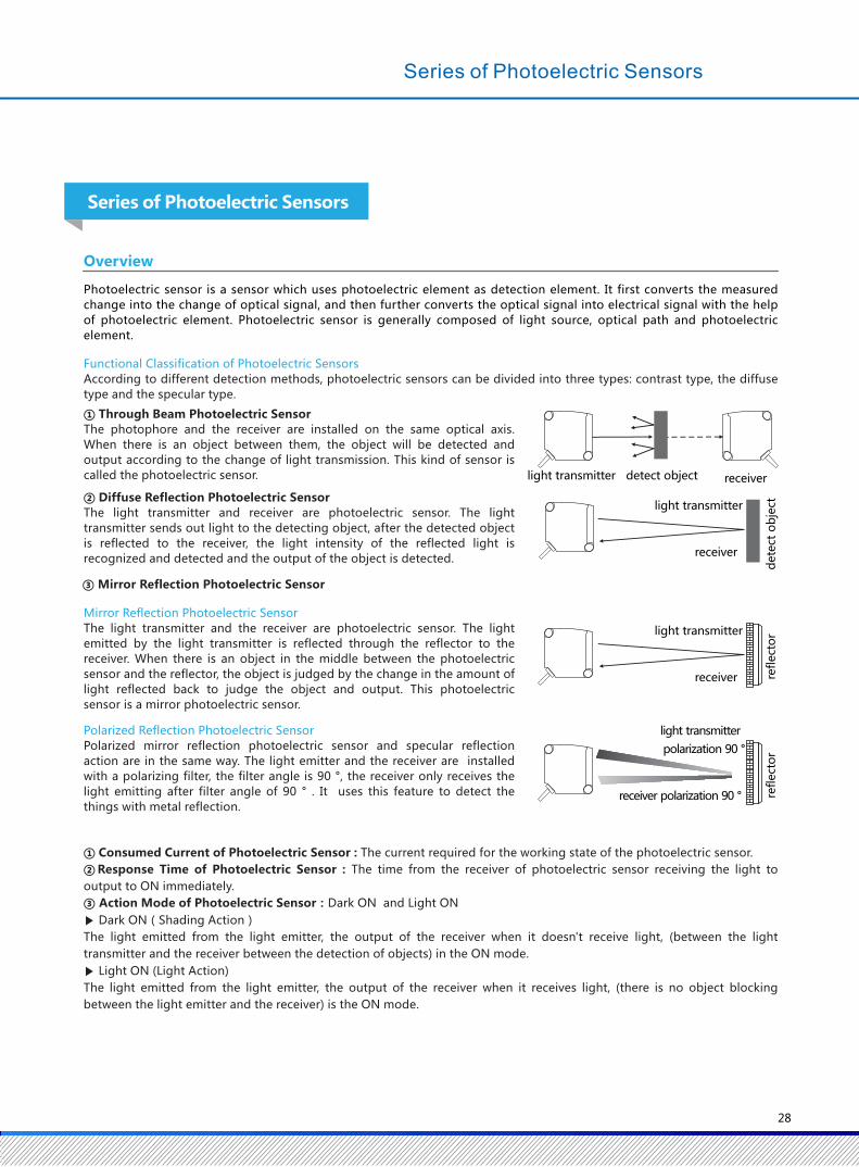
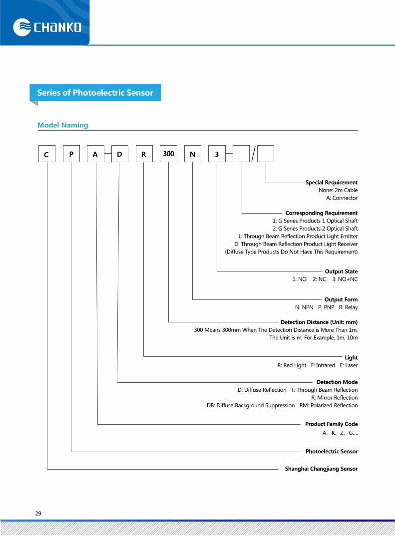
Photoelectric Sensor
C P A D R 300 N 3
Product Family Code
A、K、Z、G….
Output Form
N: NPN P: PNP R: Relay
Model Naming
Series of Photoelectric Sensor
Special Requirement
None: 2m Cable
A: Connector
Corresponding Requirement
1: G Series Products 1 Optical Shaft
2: G Series Products 2 Optical Shaft
L: Through Beam Reflection Product Light Emitter
D: Through Beam Reflection Product Light Receiver
(Diffuse Type Products Do Not Have This Requirement)
Output State
1: NO 2: NC 3: NO+NC
Detection Distance (Unit: mm)
300 Means 300mm When The Detection Distance is More Than 1m,
The Unit is m, For Example, 1m, 10m
Light
R: Red Light F: Infrared E: Laser
Detection Mode
D: Diffuse Reflection T: Through Beam Reflection
R: Mirror Reflection
DB: Diffuse Background Suppression RM: Polarized Reflection
Shanghai Changjiang Sensor
29
CPA Cylindrical Photoelectric Sensor
Red Light
Detection Mode Simple Graph Detection Distance Connection Mode Output Form Model
NPN
PNP
NPN
PNP
CPA-TR20MN3 2M
Emitter:CPA-TR20MN3-L 2M
Receiver:CPA-TR20MN3-D 2M
CPA-TR20MP3 2M
Emitter:CPA-TR20MP3-L 2M
Receiver:CPA-TR20MP3-D 2M
CPA-TR20MN3-A
Emitter:CPA-TR20MN3-L/A
Receiver:CPA-TR20MN3-D/A
CPA-TR20MP3-A
Emitter:CPA-TR20MP3-L/A
Receiver:CPA-TR20MP3-D/A
0.1~4m
NPN
PNP
NPN
PNP
CPA-RMR4MN3
CPA-RMR4MP3
CPA-RMR4MN3-A
CPA-RMR4MP3-A
100mm
300mm
1m
NPN
PNP
NPN
PNP
NPN
PNP
NPN
PNP
NPN
PNP
NPN
PNP
CPA-DR100N3
CPA-DR100P3
CPA-DR100N3-A
CPA-DR100P3-A
CPA-DR300N3
CPA-DR300P3
CPA-DR300N3-A
CPA-DR300P3-A
CPA-DR1MN3
CPA-DR1MP3
CPA-DR1MN3-A
CPA-DR1MP3-A
Through Beam
Reflection
Polarized
Reflection
Diffuse
Reflection
Cable
Cable
Cable
Cable
Cable
M12
Connector
M12
Connector
M12
Connector
M12
Connector
M12
Connector
CPA Cylindrical Photoelectric Sensor
20m
30
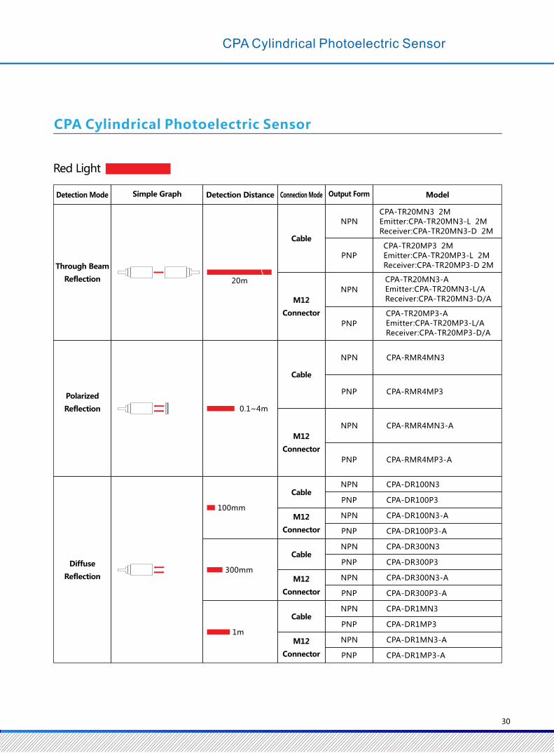

Red Infrared Ray
NPN
PNP
NPN
PNP
CPA-TF15MN3 2M
Emitter: CPA-TF15M-L 2M
Receiver: CPA-TF15MN3-D 2M
CPA-TF15MP3 2M
Emitter: CPA-TF15M-L 2M
Receiver: CPA-TF15MP3-D 2M
CPA-TF15MN3-A
Emitter: CPA-TF15M-L/A
Receiver: CPA-TF15MN3-D/A
CPA-TF15MP3-A
Emitter: CPA-TF15M-L/A
Receiver: CPA-TF15MP3-D/A
100mm
300mm
1m
NPN
PNP
NPN
PNP
NPN
PNP
NPN
PNP
NPN
PNP
NPN
PNP
CPA-DF100N3
CPA-DF100P3
CPA-DF100N3-A
CPA-DF100P3-A
CPA-DF300N3
CPA-DF300P3
CPA-DF300N3-A
CPA-DF300P3-A
CPA-DF1MN3
CPA-DF1MP3
CPA-DF1MN3-A
CPA-DF1MP3-A
15m
CPA Cylindrical Photoelectric Sensor
Detection Mode Simple Graph Detection Distance Connection Mode Output Form Model
Through Beam
Reflection
Diffuse
Reflection
Cable
Cable
M12
Connector
M12
Connector
M12
Connector
M12
Connector
Cable
Cable
31
Red Light
Red Light
CPK Rectangular AC / DC Photoelectric sensor
Relay
CPK-TR40MR3 2M
Emitter:CPK-TR40MR3-L 2M
Receiver:CPK-TR40MR3-D 2M
CPK-RMR6MR3 2M
CPK-DR300R3 2M
CPK-DR2.5MR3 2M
CPG U-Shaped Photoelectric Sensor
ThroughBeam
Reflection25mm
Formed cable (2m)
Connector relay (M8)
Formed cable (2m)
Connector relay (M8)
CPG-TF25N3-1
CPG-TF25N3-1/A
CPG-TF25N3-2
CPG-TF25N3-2/A
CPG-TF25P3-1
CPG-TF25P3-1/A
CPG-TF25P3-2
CPG-TF25N3-2/A
CPK-TR20MR3 2M
Emitter:CPK-TR20MR3-L 2M
Receiver:CPK-TR20MR3-D 2M
40m
6m
300mm
2.5m
1m
20m
CPK-DR1MR3 2M
Detection Mode Simple Graph Detection Distance Output Form Model
Through Beam
Reflection
Polarized
Reflection
Diffuse
Reflection
DetectionMode
Simple Graph DetectionWidth Connection Mode
Optical Axis
Number
Model
NPN Output PNP Output
1
Optic Axis
2
Optic Axis
CPK Rectangular AC / DC Photoelectric sensor
32

CPZ Small Rectangular Photoelectric sensor
NPN
PNP
NPN
PNP
CPZ-RMR4MN3
CPZ-RMR4MP3
CPZ-RMR4MN3-A
CPZ-RMR4MP3-A
NPN
PNP
NPN
PNP
NPN
PNP
NPN
PNP
NPN
PNP
NPN
PNP
CPZ-DF100N3
CPZ-DF100P3
CPZ-DF100N3-A
CPZ-DF100P3-A
CPZ-DF300N3
CPZ-DF300P3
CPZ-DF300N3-A
CPZ-DF300P3-A
CPZ-DF1MN3
CPZ-DF1MP3
CPZ-DF1MN3-A
CPZ-DR1MP3-A
100mm
NPN
PNP
NPN
PNP
NPN
PNP
NPN
PNP
CPZ-TF30MN3
CPZ-TF30MP3
CPZ-TF30MN3-A
CPZ-TF30MP3-A
CPZ-TF15MN3
CPZ-TF15MP3
CPZ-TF15MN3-A
CPZ-TF15MP3-A
30m
15m
4m
300mm
1m
L D
Red Infrared Ray
Detection Mode Simple Graph Detection Distance Connection Mode Output Form Model
Through Beam
Reflection
Polarized
Reflection
Diffuse
Reflection
Cable
Cable
Cable
Cable
Cable
M12
Connector
M12
Connector
M12
Connector
M12
Connector
M12
Connector
Cable
M12
Connector
33
Specification
CPA-DR1MN3
CPA-DR1MN3-A
CPA-DR1MP3
CPA-DR1MP3-A
1m
120×150mm40×45mm 40×50mm
Type
NPN output
NPN output
PNP output
PNP output
CPA-TR20MN3
CPA-TR20MN3-A
CPA-TR20MP3
CPA-TR20MP3-A
20m
CPA-RMR4MN3
0.1~4m
CPA-DR100N3
CPA-DR100N3-A
CPA-DR100P3
CPA-DR100P3-A
100mm
CPA-DR300N3
CPA-DR300N3-A
CPA-DR300P3
CPA-DR300P3-A
300mm
Min 2°
Red light emitting diode(617nm)
DC12~24V ripple (P-P) less than 10% (DC10~30V)
Less than 25mA
NPN/PNP (collector open-circuit output) load current less than 100mA (residual voltage less than 3V), load supply voltage less than 30V
Dark ON / Light ON select by wire connection
0.5ms
-
ABS
成型电缆重量:约65g
M12接插件重量:约65g
1ms (0.5ms is upgrading)
PDM
POM
ABS
-
CPA-RMR4MN3-A
CPA-RMR4MP3-A
CPA-RMR4MP3
Below 40mA (Emitter below
25mA, Receiver below 15mA)
CPA Cylindrical ( 18 mm) Photoelectric Sensor
▶ Adopt advanced visible red light technology;
▶ Fast response time: 0.5ms;
▶ Action mode Dark ON/Light ON switches freely;
▶ Strong anti-interference ability
▶ Stable and reliable performance, good consistency, high cost performance.
▶ Long detection distance, through beam reflection up to 20m, diffuse reflection up to 1m;
Sensor Type Through Beam Reflection Polarized Reflection Diffuse Reflection
Cable
Cable
Connector
Connector
Opaque objects above φ 7mm opaque objects above φ 75mm White paper:300×300mm
Action indicator (orange)
Stable indicator (green)
Power indicator (green): through beam emitter only
Power supply reverse connection protection, surge absorption, load short circuit protection
Single knob
Lighting collecting surface illumination incandescent lamp: less than 3000lx, sunlight: less than 10000lx
Working: -25 ~ 55 ℃ / Storing: -40 ~ 70 ℃ (no freeze, no dew)
Working: 35~85%RH/ Storing: 35~95%RH (no dew)
Above 20MΩ(DC500VMeg-ohmmeter)
AC 1,000V 50/60Hz 1min between the whole charging part and the shell
Up and down 1.5mm at 10~55Hz for each 2 hours in X / Y / Z directions
300m/s² for each 3 times in X / Y / Z directions
IEC standard IP65 (Note: no knob IP67)
Cable Weight: about 94g
M12 connector weight: about 80g
Cable weight: about 50g
M12 connector weight: about 55g
Instructions, M18 nuts (4)Reflector, instructions,
M18 nuts (2)Instructions, M18 nuts (2)
Detection Distance
Spot Diameter (Reference Value)
Standard Detection Object
Direction Angle
Light Source (Wavelength)
Supply Voltage
Consumed Current
Control Output
Action Mode
Indicator
Protection Circuit
Response Time
Sensitivity Adjustment
Ambient Illumination (Receiver Side)
Ambient Temperature Range
Ambient Humidity Range
Insulation Resistance
Withstand Voltage
Vibration
Impact
IP Grade
Weight (Packing Status
/ Sensors Only)
Cable (2m)
Connector
Material
Case
Lens / Display Window
Knob
Nut
Accessory
34
CPA Cylindrical ( 18 mm) Photoelectric Sensor
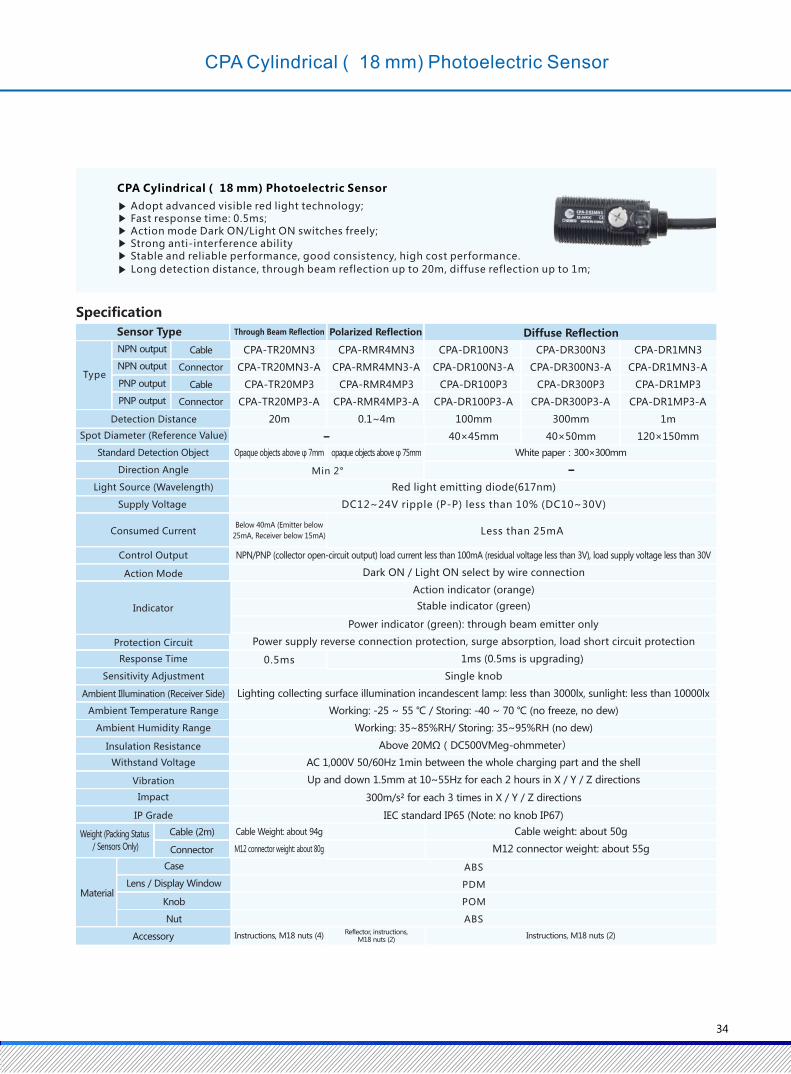

Specification
1m
120×150mm40×45mm 40×50mm
CPA-DF100N3
CPA-DF100N3-A
CPA-DF100P3
CPA-DF100P3-A
100mm 300mm
CPA-TF15MN3
CPA-TF15MN3-A
CPA-TF15MP3
CPA-TF15MP3-A
CPA-DF300N3
CPA-DF300N3-A
CPA-DF300P3
CPA-DF300P3-A
CPA-DF1MN3
CPA-DF1MN3-A
CPA-DF1MP3
CPA-DF1MP3-A
15m
-
-
-
About 94g
About 80g
About 50g
About 55g
ABS
PDM
POM
ABS
CPA Cylindrical ( 18 mm) Photoelectric Sensor
◆ Red LED state indicator
◆ Adopt infrared technology
◆ Action mode: Dark ON/Light ON switches freely
◆ Fast response time: 0.5ms; Screw thread cylindrical appearance
◆ Stable and reliable performance, good consistency, high cost performance
◆ Long detection distance, through beam reflection up to 15m, diffuse reflection up to 1m
Sensor Type
Type
NPN output Cable
NPN output Connector
PNP output Cable
PNP output Connector
Detection Distance
Spot Diameter (Reference Value)
Standard Detection Object
Return Difference
Direction Angle
Light Source (Wavelength)
Supply Voltage
Consumed Current
Control Output
Action Mode
Indicator
Protection Circuit
Response Time
Sensitivity Adjustment
Ambient Illumination (Receiver Side)
Ambient Temperature Range
Ambient Humidity Range
Insulation Resistance
Withstand Voltage
Vibration (Durability)
Impact (Durability)
IP Grade
ProductWeight
Cable
M12 Connector
Material
Case
Lens / Display Window
Knob
Nut
Accessory
Through Beam Reflection Diffuse Reflection
Opaque objects above φ 7mm
Minimum 2°
White paper:300×300mm
The detection distance is less than 20%
Red infrared ray emitting diode(850nm)
DC12~24V ripple (P-P) less than 10% (DC10~30V)
Below 40mA (Emitter below 25mA, Receiver below 15mA) Less than 25mA
NPN/PNP (collector open-circuit output) load current below 100mA (residual voltage below 3V), load supply voltage less than 30V
Dark ON / Light ON select by wire connection
Action indicator (orange)
Stable indicator (green)
Power indicator (green): through beam emitter only
Power supply reverse connection protection, surge absorption, load short circuit protection
0.5ms 1ms (0.5ms is upgrading)
Single knob
Lighting collecting surface illumination incandescent lamp: below 3000lx, sunlight: less than 10000lx
Working: -25 ~ 55 ℃ / Storing: -40 ~ 70 ℃ (no freeze, no dew)
Working: 35~85%RH/ Storing: 35~95%RH (no dew)
Above 20MΩ(DC500VMeg-ohmmeter)
AC 1,000V 50/60Hz 1min between the whole charging part and the shell
IEC standard IP65 (Note: no knob IP67)
Instructions, M18 nuts (4) Instructions, M18 nuts (2)
35
Up and down 1.5mm at 10~55Hz for each 2 hours in X / Y / Z directions
300m/s² for each 3 times in X / Y / Z directions
NPN
CPA Control Output Diagram
CPA Outline Dimension Diagram
●Product Model:CPA-RMR4M□3/ CPA-DR□□3
●Product Model:CPA-TR20M□3
18.5
18.5
Note: when the pink line is not connected,
the default is the Light-ON (NO) action.
Note: when the pink line is not connected,
the default is the Light-ON (NO) action.
+V
0V
Light-ON
Dark-ONPhotoelectric
Sensor Main Circuit
+V
0V
Light-ON
Dark-ON
LOAD
+V
0V
Connector Pin Configuration
M12 Connector Pin Configuration
1
2
3
4
1
2
3
4
+V
L/ON.D/ON
-V
PNP
BROWN
BLACK
BLUE
PINK
Photoelectric Sensor
Main Circuit
BROWN
BLACK
BLUE
PINK
LOAD
Cable Color
Brown
Pink
Blue
Black
Specification
Output
NO.
Through Beam Reflection Light Emitter
Photoelectric Sensor
Main Circuit
BROWN
BLUE
Emitter
Receiver
Optical axis
Sensitivity knob
Action indicator (orange)
Stable indicator (green)
Vinyl circular insulated conductor, 4.4 core2Conductor cross section area: 0.128mm (AWG26)
Insulator outer diameter: ∅0.85Standard length: 2m
Mounting hole
Reflector
Sensitivity knob
Action indicator (orange)
Stable indicator (green)
Vinyl circular insulated conductor, 4.4 core2
Conductor cross section area: 0.128mm (AWG26)
Insulator outer diameter: 0.85Standard length: 2m
Action indicator (orange)
Stable indicator (green)
Vinyl circular insulated conductor, 4.4 core2Conductor cross section area: 0.128mm (AWG26)
Insulator outer diameter: 0.85Standard length: 2m Optical axis
mounting hole
40.9
59.9
52
34
7.5
4.8
8
2- 3.5
36
CPA Cylindrical ( 18 mm) Photoelectric Sensor

Specification
1m
120×150mm40×45mm 40×50mm
CPA-DF100N3
CPA-DF100N3-A
CPA-DF100P3
CPA-DF100P3-A
100mm 300mm
CPA-TF15MN3
CPA-TF15MN3-A
CPA-TF15MP3
CPA-TF15MP3-A
CPA-DF300N3
CPA-DF300N3-A
CPA-DF300P3
CPA-DF300P3-A
CPA-DF1MN3
CPA-DF1MN3-A
CPA-DF1MP3
CPA-DF1MP3-A
15m
-
-
-
About 94g
About 80g
About 50g
About 55g
ABS
PDM
POM
ABS
CPA Cylindrical ( 18 mm) Photoelectric Sensor
◆ Red LED state indicator
◆ Adopt infrared technology
◆ Action mode: Dark ON/Light ON switches freely
◆ Fast response time: 0.5ms; Screw thread cylindrical appearance
◆ Stable and reliable performance, good consistency, high cost performance
◆ Long detection distance, through beam reflection up to 15m, diffuse reflection up to 1m
Sensor Type
Type
NPN output Cable
NPN output Connector
PNP output Cable
PNP output Connector
Detection Distance
Spot Diameter (Reference Value)
Standard Detection Object
Return Difference
Direction Angle
Light Source (Wavelength)
Supply Voltage
Consumed Current
Control Output
Action Mode
Indicator
Protection Circuit
Response Time
Sensitivity Adjustment
Ambient Illumination (Receiver Side)
Ambient Temperature Range
Ambient Humidity Range
Insulation Resistance
Withstand Voltage
Vibration (Durability)
Impact (Durability)
IP Grade
ProductWeight
Cable
M12 Connector
Material
Case
Lens / Display Window
Knob
Nut
Accessory
Through Beam Reflection Diffuse Reflection
Opaque objects above φ 7mm
Minimum 2°
White paper:300×300mm
The detection distance is less than 20%
Red infrared ray emitting diode(850nm)
DC12~24V ripple (P-P) less than 10% (DC10~30V)
Below 40mA (Emitter below 25mA, Receiver below 15mA) Less than 25mA
NPN/PNP (collector open-circuit output) load current below 100mA (residual voltage below 3V), load supply voltage less than 30V
Dark ON / Light ON select by wire connection
Action indicator (orange)
Stable indicator (green)
Power indicator (green): through beam emitter only
Power supply reverse connection protection, surge absorption, load short circuit protection
0.5ms 1ms (0.5ms is upgrading)
Single knob
Lighting collecting surface illumination incandescent lamp: below 3000lx, sunlight: less than 10000lx
Working: -25 ~ 55 ℃ / Storing: -40 ~ 70 ℃ (no freeze, no dew)
Working: 35~85%RH/ Storing: 35~95%RH (no dew)
Above 20MΩ(DC500VMeg-ohmmeter)
AC 1,000V 50/60Hz 1min between the whole charging part and the shell
IEC standard IP65 (Note: no knob IP67)
Instructions, M18 nuts (4) Instructions, M18 nuts (2)
35
Up and down 1.5mm at 10~55Hz for each 2 hours in X / Y / Z directions
300m/s² for each 3 times in X / Y / Z directions
NPN
CPA Control Output Diagram
CPA Outline Dimension Diagram
●Product Model:CPA-RMR4M□3/ CPA-DR□□3
●Product Model:CPA-TR20M□3
18.5
18.5
Note: when the pink line is not connected,
the default is the Light-ON (NO) action.
Note: when the pink line is not connected,
the default is the Light-ON (NO) action.
+V
0V
Light-ON
Dark-ONPhotoelectric
Sensor Main Circuit
+V
0V
Light-ON
Dark-ON
LOAD
+V
0V
Connector Pin Configuration
M12 Connector Pin Configuration
1
2
3
4
1
2
3
4
+V
L/ON.D/ON
-V
PNP
BROWN
BLACK
BLUE
PINK
Photoelectric Sensor
Main Circuit
BROWN
BLACK
BLUE
PINK
LOAD
Cable Color
Brown
Pink
Blue
Black
Specification
Output
NO.
Through Beam Reflection Light Emitter
Photoelectric Sensor
Main Circuit
BROWN
BLUE
Emitter
Receiver
Optical axis
Sensitivity knob
Action indicator (orange)
Stable indicator (green)
Vinyl circular insulated conductor, 4.4 core2Conductor cross section area: 0.128mm (AWG26)
Insulator outer diameter: ∅0.85Standard length: 2m
Mounting hole
Reflector
Sensitivity knob
Action indicator (orange)
Stable indicator (green)
Vinyl circular insulated conductor, 4.4 core2
Conductor cross section area: 0.128mm (AWG26)
Insulator outer diameter: 0.85Standard length: 2m
Action indicator (orange)
Stable indicator (green)
Vinyl circular insulated conductor, 4.4 core2Conductor cross section area: 0.128mm (AWG26)
Insulator outer diameter: 0.85Standard length: 2m Optical axis
mounting hole
40.9
59.9
52
34
7.5
4.8
8
2- 3.5
36
CPA Cylindrical ( 18 mm) Photoelectric Sensor

CPK-RMR6MR3
Less than 20% of detection distance--
Red emitting diode (617nm)
DC24~240V±10% Pulsation (P-P) is less than 10% AC24~240V±10% 50/60Hz
Relay output: 1c contact AC250V less than 3A (cos φ = 1), DC5V above 10mA
0.1~6m
Dark ON / Light On switches freely
Action indicator (orange)
Stable indicator (green)
Power indicator (green) : through beam emitter only
Function of preventing mutual interference-
About 215g About 146g About 132g
ABS
PDM
40m
CPK-TR20MR3CPK-TR40MR3
20m
CPK-DR300R3
300mm
CPK-DR1MR3
1m
CPK-DR2.5MR3
2.5m
Less than 3W (transmitter less than 1.5W optometer less than 1.5W) Less than 2W
Sensor Type Through Beam Reflection Polarized Reflection Diffuse Reflection
Type Relay Output
Detection Distance
Standard Detection Object
Return Difference
Direction Angle
Light Source (Wavelength)
Supply Voltage
Consumed Power/ Consumed Current
Control Output
Action Mode
Indicator
Protection Circuit
Life (Relay Output)
Machinery
Electrical
Response Time
Sensitivity Adjustment
Ambient Illumination (Receiver Side)
Ambient Temperature Range
Ambient Humidity Range
Insulation Resistance
Withstand Voltage
Vibration (Durability)
Impact (Durability)
IP Grade
Connection Mode
Weight (Packing State)
Shell
Case
Lens / Display Window
Cable
Accessory
Opaque objects above Φ17mm Opaque objects above Φ75mm White paper:100×100mm White paper:300×300mm
Emitter, receiver: above 3° Above 1.5°
More than 50 million times (switching frequency is 18000 times / h)
More than 100000 times (switching frequency is 18000 times / h)
Less than 20ms
Single knob (receiver only)
Lighting collecting surface illumination incandescent lamp: less than 3000lx, sunlight: less than 11000lx
Working: -25~55 ℃ / Storing: -40~70 ℃ (no freeze, no dew)
Working: 35~85%RH / Storing: 35~95%RH (no dew)
Above 20m (DC500V megabit meter)
AC1,500V 50/60Hz 1min between the whole charging part and the shell
IEC standard IP65 (Note: no knob IP67)
Lead out type (standard conductor 2m)
2m PVC cable cable bend radius:R18
Instructions, mounting bracket Instructions, mounting
bracket, reflectorInstructions, mounting bracket
CPK Rectangular Photoelectric sensor
▶ Adopt advanced technology visible red light;
▶ Action mode: Dark ON/Light ON switches freely;
▶ Strong anti-interference ability
▶ Long detection distance, through beam reflection up to 40m, diffuse reflection up to 2.5m;
Specification
37
Up and down 1.5mm at 10~55Hz for each 2 hours in X / Y / Z directions
300m/s² for each 3 times in X / Y / Z directions
Relay Output
● CPK-TR□□□□
● CPK-RMR6MR3 / CPK-DR300R3/ CPK-DR1MR3/ CPK-DR2.5MR3
CPK Control Output Diagram
CPK Outline Dimension Diagram
Vinyl insulated wires, 62 Conductor cross section area: 0.3 mm (AWG26)
Insulation outside diameter: 1.5
Standard length: 2m
2- 4.5M4 mounting
holes Recommended
torque 0.8n.m
(below 1.2n.m)
Action indicator
(orange)
Steady indicator
(green)
AC/DC
24-220V
Photoelectric SensorMain Circuit
AC/DC
24-220V
Relay Output
AC 250V 3A
Emitter
Action indicator (orange)
Solid indicator (green)
50±0.05
40±0.05▽
10xR5
2x(
40)
2x54.7
5±
0.0
5▽
24±0.05
58±0.05
4xR2.25
2x4
5.0
0°±
0.1
5°
2x10°
2x3
0.0
0°±
0.0
3°
2x22±
0.0
7
2x47.5
±0.0
7
2x15.0
0°±
0.0
3°
2x 4.5
2xR56.6
Reflector
Holder
BROWN
BLUE
WHITE
BLACK
GRAY
Through Beam Reflection Light Emitter
Photoelectric Sensor
Main Circuit
BROWN
BLUE
Sensitivity knob Action switch
Emitter
Receiver
Receiver
Sensitivity knob Action switch
Emitter
Optical axis
Receiver
13.1
40.9
59.9
52
34
7.5
4.8
8
2- 3.5
38
CPK Rectangular Photoelectric sensor
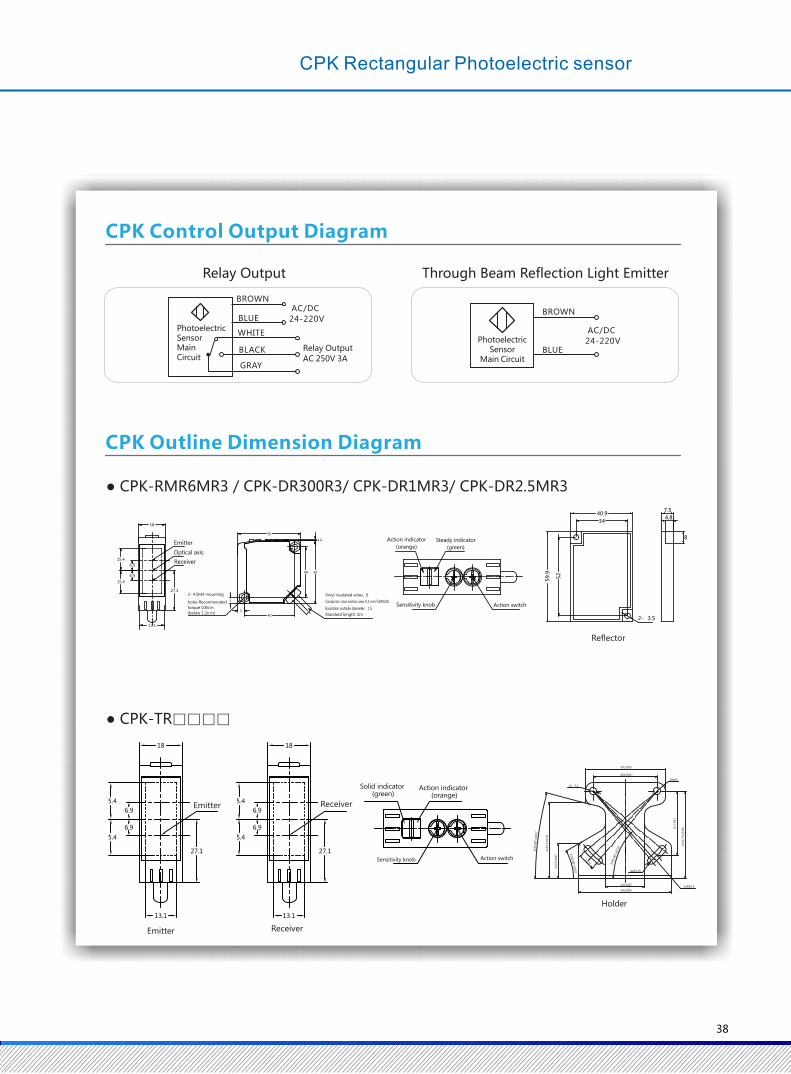

Specification
CPZ-TF30MN3
CPZ-TF30MN3-A
CPZ-TF30MP3
CPZ-TF30MP3-A
CPZ-TF15MN3
CPZ-TF15MN3-A
CPZ-TF15MP3
CPZ-TF15MP3-A
CPZ-RMF4MN3
CPZ-RMRFMN3-A
CPZ-RMF4MP3
CPZ-RMF4MP3-A
CPZ-DF100N3
CPZ-DF100N3-A
CPZ-DF100P3
CPZ-DF100P3-A
CPZ-DF300N3
CPZ-DF300N3-A
CPZ-DF300P3
CPZ-DF300P3-A
CPZ-DF1MN3
CPZ-DF1MN3-A
CPZ-DF1MP3
CPZ-DF1MP3-A
30m 15m 4m 100mm 300mm 1m
-
-
--
2-10°
DC12~24V 纹波(p-p)10%以下
About 120g
About 40g
About 65g
About 20g
ABS
PMMA
Abou t80g
About 25g
CPZ Small Rectangular Photoelectric sensor
▶ Red LED state indicator
▶ Multiple protection circuit
▶ Strong anti-interference ability
▶ Easy to install in a narrow space
▶ Stable and reliable performance, good consistency,high cost performance
Sensor Type
NPN Cable
NPN Connector
Connector
PNP Cable
PNP
Detection Distance
Spot Diameter (Reference Value)
Standard Object Detection
Return Difference
Direction Angle
Light Source (Wavelength)
Supply Voltage
Consumed Current
Control Output
Action Mode
Indicator
Protection Circuit
Response Time
Sensitivity Adjustment
Ambient Illumination (Receiver Side)
Ambient Temperature Range
Ambient Humidity Range
Insulation Resistance
Withstand Voltage
Vibration (Durable)
Impact (Durable)
IP Grade
WeightCable (2m)
Connector
Material
Case
Lens / DisplayWindow
Cable
Accessory
Through Beam Reflection PolarizedReflection Diffuse Reflection
Opaque objects above φ 12mmOpaque objectsabove φ 75mm
White paper:100×100mm
White paper:300×300mm
Less than 20% of detection distance
Emitter/Receiver: 3-15 °
Red infrared ray emitting diode(870nm) Red emittingdiode(660nm)
Red infrared ray emitting diode(860nm)
DC12~24V ripple (P-P) less than 10%
Below 35mA (Emitter below 15mA,Receiver below 20mA) Less than 30mA
NPN/PNP (collector open-circuit output) load current below 100mA (Residual voltage load current below 10mA:below 1V, load current 10-100mA:below 2V), load supply voltage below DC 26.4V
Dark ON / Light ON mode switching
Action indicator (orange)
Stable indicator (green)
Power indicator (green): through beam emitter only
Power supply reverse connection protection, output short circuitprotection, output reverse connection protection
Power supply reverse connection protection, output short circuit protection, output reverseconnection protection and mutual interference prevention function
Action and reset: below 2ms Action and reset: below 1ms
Single knob
Lighting collecting surface illumination incandescent lamp: below 3000lx, sunlight: below 10000lx
Working: -25 ~ +55 ℃ / Storing: -40 ~+ 70 ℃ (no freeze, no dew)
Working: 35~85%RH/ Storing: 35~95%RH (no dew)
Above 20MΩ(DC500V Meg-ohmmeter)
AC 1,000V 50/60Hz 1min between the whole charging part and the shell
IEC standard IP65
2m PVC
Instructions,mounting bracket Instructions,mounting bracket,reflector Instructions,mounting bracket
39
T
Y
P
E
Up and down 1.5mm at 10~55Hz for each 2 hours in X / Y / Z directions
300m/s² for each 3 times in X / Y / Z directions
CPZ Control Output Diagram
CPZ Outline Dimension Diagram
Product Type: CPZ-RMR4M□3/□/CPZ-DF□□□3/□
831
2.4 10.6
Receiver Lensφ7.5
Emitter Lensφ7.5
Product Type:CPZ-TF□□□3/□
3
20
2- 2,4
2.9
16.6
40.9
59.9
52
34
7.54.8
8
2-φ3.5
831
2.4 10.6
Receiver
Lens φ7.5
Emitter
Lensφ7.5
7.5
11.2
4.5
Action indicator (orange)
Stable indicator(green)
Action switch
Sensitivity knobReflector
Polyvinyl chloride circular
insulated conductor φ4、3core
Conductor cross section area:0.2mm² ) (AWG24
Insulator diameter:φ1.1mm
Standard length: 2m
NPN PNP
+V
0VPhotoelectric
Sensor Main Circuit
BROWN
BLACK
BLUE
LOAD
+V
0VPhotoelectric
Sensor Main Circuit
LOAD
BROWN
BLACK
BLUE
40
CPZ Small Rectangular Photoelectric sensor
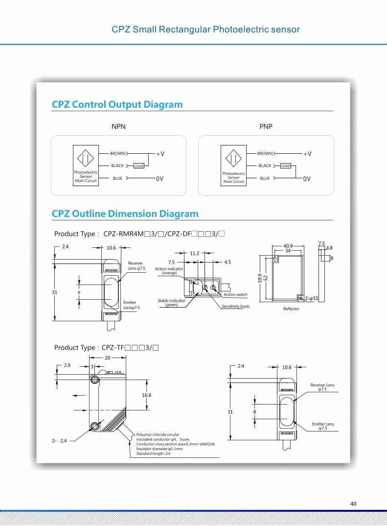

Weight
(wrapping State)
1 Optical Axis
CPG-TF25N3-1
CPG-TF25N3-1/A
CPG-TF25P3-1
CPG-TF25P3-1/A
2 Optical Axis
CPG-TF25N3-2
CPG-TF25N3-2/A
CPG-TF25P3-2
CPG-TF25P3-2/A
25mm
Above Φ1.5mm opaque objects
Infrared emitting diode (940nm)
DC12~24V ripple (P-P) less than 10%(DC10~30V)
CPG U-Shaped Photoelectric Sensor
▶ Fast response: 1ms
▶ Action mode: Dark ON/Light switch ON freedom
▶ Strong anti-interference ability
▶ IP67 grade
▶ Stable and reliable performance, good consistency, high cost performance
Cable 2m
Material
Detection Distance (Slot Width)
Standard Detection Object
Light Source (Wavelength)
Supply Voltage
Consumption Current
Control Output
Action Mode
Loop Response Time
Ambient Illumination
Ambient Temperature Range
Ambient Humidity Range
Insulation Resistance
Withstand Voltage
Vibration (Durability)
Impact (Durability)
IP Grade
Connection Mode
Indicator
Accessory
Connector
Case
Optical Axis Number
NPN Output
NPN Output
PNP Output
Through BeamReflection
Type
Less than 25mA Less than 40mA
The load current is less than 100mA (residual voltage is less than 1V), and the load supply voltage is less than DC26.4V
Dark ON / Light ON select by wire connection
1ms
Light collecting surface illumination Incandescent lamps: less than 3,000lx, sunlight: less than 10,000lx
Working: -25 ~ 55 ℃ / Storing: -40 ~ 70 ℃ (no freeze, no dew)
Working: 35~85%RH / Storing: 35~95%RH (no dew)
Above 20MΩ(DC500V megger)
AC1,000V 50/60Hz 1min between the whole charging part and the shell
IEC Standard IP67
Cable (standard cable 2m) / connector relay type (standard cable 300mm)
Action display indicator (orange)
2m PVC weight: about 52g
M8 connector weight: about 50g
ABS
Instructions
Specification
Protection CircuitPower supply reverse connection protection, surge absorption, load short circuit protection,
mutual interference prevention function
Cable
Connector
PNP Output Cable
Connector
41
Up and down 1.5mm at 10~55Hz for each 2 hours in X / Y / Z directions
300m/s² for each 3 times in X / Y / Z directions
NPN PNP
● CPG-TF25N3-1/ CPG-TF25P3-1 (1 Optic Axis)
NPN PNP
● CPG-TF25N3-2/ CPG-TF25P3-2 (2 Optic Axis)
CPG Control Output Diagram
CPG Outline Dimension Diagram
+V
0VPhotoelectric
SensorMain Circuit
Light-ON
Dark-ON
+V
0V
Light-ON
+V
0V
Light-ON
Dark-ON
+V
0V
Light-ON
Dark-ON
Note: When the pink line is not connected,
the default is light-ON (NO) action.
¢4
11
26 28
40
1536
50
11
S1 S2
¢6
BROWN
BLACK
BLUE
PINK
load Output
Photoelectric Sensor
Main Circuit
BLACK
BLUE
PINK
load Output
BLACK
WHITE
BLUE
PINK
Load
Load
Output 1Output 2 BLACK
WHITE
BLUE
PINK
LoadLoad
Output 1
Output 2
Note: When the pink line is not connected,
the default is light-ON (NO) action.
Note: When the pink line is not connected,
the default is light-ON (NO) action.
Note: When the pink line is not connected,
the default is light-ON (NO) action.
BROWN
BROWN BROWN
Photoelectric Sensor
Main Circuit
Photoelectric Sensor
Main Circuit
CPG U-Shaped Photoelectric Sensor
42
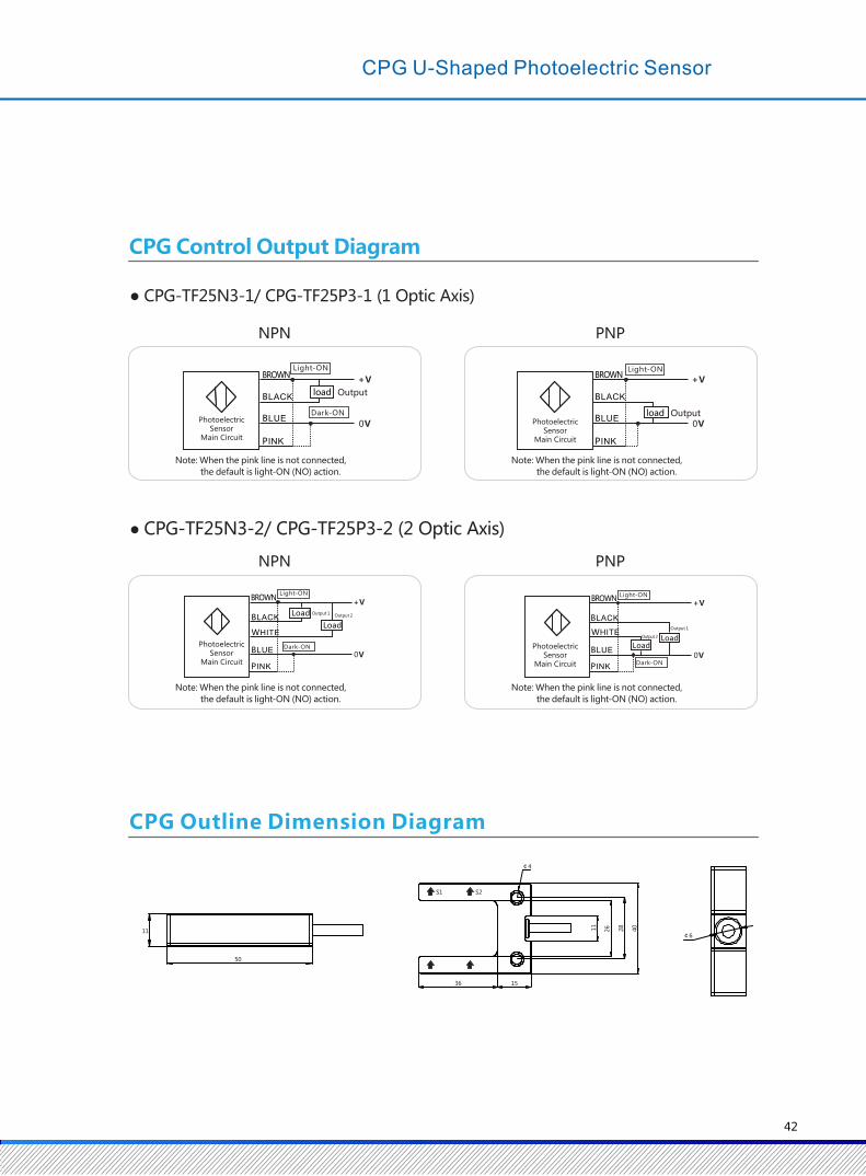
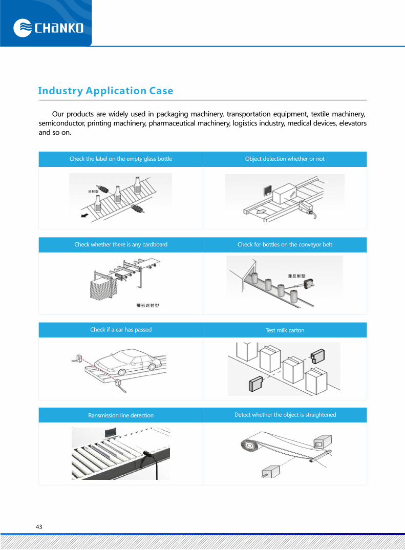
Our products are widely used in packaging machinery, transportation equipment, textile machinery,
semiconductor, printing machinery, pharmaceutical machinery, logistics industry, medical devices, elevators
and so on.
Check if a car has passed
Ransmission line detection
Test milk carton
Detect whether the object is straightened
Industry Application Case
Check the label on the empty glass bottle Object detection whether or not
Check whether there is any cardboard Check for bottles on the conveyor belt
43
C
Series of Fiber Optic Sensors
X 6 D N 10
C X 2 D 3 F L C
Model Naming
Connection ModeA: M12 Relay TypeNone: Cable
Function 10:With Light Compensation
30:Standard
Output Form N:NPN P:PNP
Rated Supply Voltage: 12-24VDC
Product Code
Optic Fiber Sensor
Shanghai Changjiang Sensor
Head Diameter Unit: mm E.g.: 0.8/1.5/1.2
Fiber Cable Length
None: 2m 10: 1m 30: 3m 50: 5m
Fiber Cable TypeNone: Standard, C: Coaxial
Fiber Cable Shape L: Line T: 90°Right Angle
Fiber Cable Material F: Plastic G: Glass
Fiber Cable Head Diameter 3: M3 4: M4 6: M6
Detection Mode D: Diffuse Reflection T: Through Beam Reflection
Fiber Cable Code
Fiber Cable Series
Shanghai Changjiang Sensor
Series of Fiber Optic Sensors
44
Head Length
Unit: mm E.g.: 5/10/12
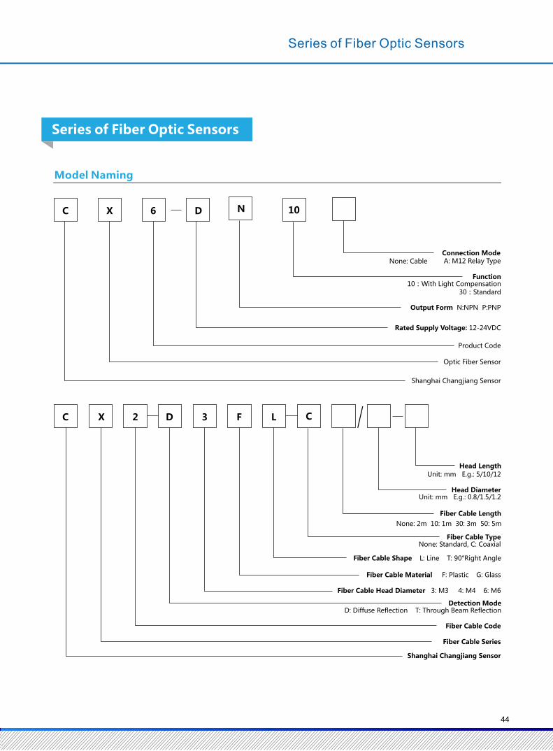
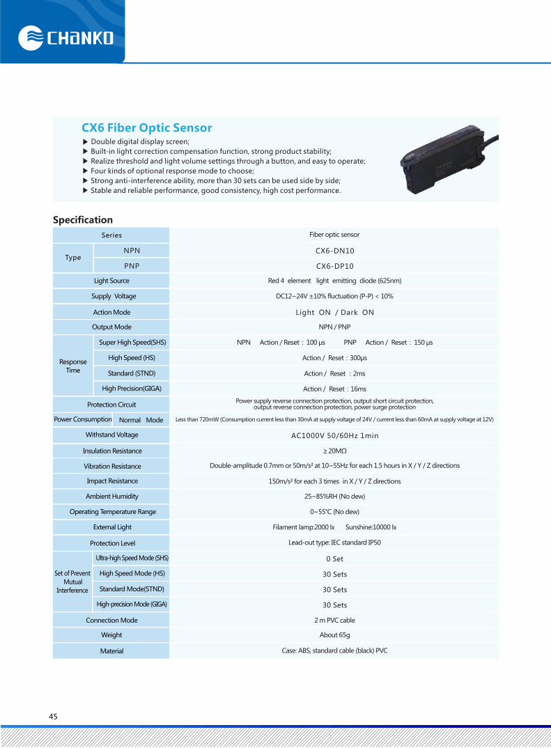
NPN
PNP
Response
Time
CX6 Fiber Optic Sensor▶ Double digital display screen;
▶ Built-in light correction compensation function, strong product stability;
▶ Realize threshold and light volume settings through a button, and easy to operate;
▶ Four kinds of optional response mode to choose;
▶ Strong anti-interference ability, more than 30 sets can be used side by side;
▶ Stable and reliable performance, good consistency, high cost performance.
CX6-DN10
CX6-DP10
Light ON / Dark ON
AC1000V 50/60Hz 1min
0 Set
30 Sets
30 Sets
30 Sets
Series
Type
Light Source
Supply Voltage
Action Mode
Output Mode
Super High Speed(SHS)
High Speed (HS)
Standard (STND)
High Precision(GIGA)
Fiber optic sensor
Red 4 element light emitting diode (625nm)
DC12~24V ±10% fluctuation (P-P) < 10%
NPN / PNP
NPN Action / Reset: 100 μs PNP Action / Reset: 150 μs
Action / Reset:300μs
Action / Reset :2ms
Action / Reset:16ms
Power supply reverse connection protection, output short circuit protection, output reverse connection protection, power surge protection
Less than 720mW (Consumption current less than 30mA at supply voltage of 24V / current less than 60mA at supply voltage at 12V)
≥ 20MΩ
Double-amplitude 0.7mm or 50m/s² at 10~55Hz for each 1.5 hours in X / Y / Z directions
150m/s² for each 3 times in X / Y / Z directions
25~85%RH (No dew)
0~55℃ (No dew)
Filament lamp:2000 lx Sunshine:10000 lx
Lead-out type: IEC standard IP50
2 m PVC cable
About 65g
Case: ABS, standard cable (black) PVC
Protection Circuit
Power Consumption Normal Mode
Withstand Voltage
Insulation Resistance
Vibration Resistance
Impact Resistance
Ambient Humidity
Operating Temperature Range
External Light
Protection Level
Set of Prevent
Mutual
Interference
Ultra-high Speed Mode (SHS)
High Speed Mode (HS)
Standard Mode(STND)
High-precision Mode (GIGA)
Connection Mode
Weight
Material
Specification
45
CX6 Fiber Optic Sensor
▶ Double digital display screen
▶ Four kinds of optional response mode to choose
▶ Stable and reliable performance, good consistency, high cost performance
▶ Strong anti-interference ability, more than 30 sets can be used side by side
▶ Realize threshold and light volume settings through a button, and easy to operate
NPN
PNP
Response
Time
Series
Type
Light Source
Supply Voltage
Action Mode
Output Mode
Super High Speed(SHS)
High Speed (HS)
Standard (STND)
High Precision(GIGA)
Protection Circuit
Power Consumption Normal Mode
Withstand Voltage
Insulation Resistance
Vibration Resistance
Impact Resistance
Ambient Humidity
Operating Temperature Range
External Light
Protection Level
Set Of Prevent
Mutual
Interference
Ultra-high Speed Mode (SHS)
High Speed Mode (HS)
Standard Mode(STND)
High-precision Mode (GIGA)
Connection Mode
Weight
Material
Fiber optic sensor
CX6-DN30
CX6-DP30
Red 4 element light emitting diode (625nm)
DC12~24V ±10% fluctuation (P-P) < 10%
Light ON / Dark ON
NPN / PNP
Action / Reset:200μs
Action / Reset:350μs
Action / Reset :3ms
Action / Reset:18ms
Power supply reverse connection protection, output short circuit protection, output reverse connection protection, power surge protection
Less than 720mW (Consumption current below 30mA at supply voltage of 24V / current less than 60mA at supply voltage at 12V)
AC1000V 50/60Hz 1min
≥ 20MΩ
Double-amplitude 0.7mm or 50m/s² at 10~55Hz for each 1.5 hours in X / Y / Z directions
150m/s² for each 3 times in X / Y / Z directions
25~85%RH (No dew)
0~55℃ (No dew)
Filament lamp:2000 lx Sunshine:10000 lx
Lead-out type: IEC standard IP50
0 Set
30 Sets
30 Sets
30 Sets
2 m PVC cable
About 65g
Case: ABS, standard cable (black) PVC
46
Specification
CX6 Fiber Optic Sensor

NPN
PNP
Response
Time
CX6 Fiber Optic Sensor▶ Double digital display screen;
▶ Built-in light correction compensation function, strong product stability;
▶ Realize threshold and light volume settings through a button, and easy to operate;
▶ Four kinds of optional response mode to choose;
▶ Strong anti-interference ability, more than 30 sets can be used side by side;
▶ Stable and reliable performance, good consistency, high cost performance.
CX6-DN10
CX6-DP10
Light ON / Dark ON
AC1000V 50/60Hz 1min
0 Set
30 Sets
30 Sets
30 Sets
Series
Type
Light Source
Supply Voltage
Action Mode
Output Mode
Super High Speed(SHS)
High Speed (HS)
Standard (STND)
High Precision(GIGA)
Fiber optic sensor
Red 4 element light emitting diode (625nm)
DC12~24V ±10% fluctuation (P-P) < 10%
NPN / PNP
NPN Action / Reset: 100 μs PNP Action / Reset: 150 μs
Action / Reset:300μs
Action / Reset :2ms
Action / Reset:16ms
Power supply reverse connection protection, output short circuit protection, output reverse connection protection, power surge protection
Less than 720mW (Consumption current less than 30mA at supply voltage of 24V / current less than 60mA at supply voltage at 12V)
≥ 20MΩ
Double-amplitude 0.7mm or 50m/s² at 10~55Hz for each 1.5 hours in X / Y / Z directions
150m/s² for each 3 times in X / Y / Z directions
25~85%RH (No dew)
0~55℃ (No dew)
Filament lamp:2000 lx Sunshine:10000 lx
Lead-out type: IEC standard IP50
2 m PVC cable
About 65g
Case: ABS, standard cable (black) PVC
Protection Circuit
Power Consumption Normal Mode
Withstand Voltage
Insulation Resistance
Vibration Resistance
Impact Resistance
Ambient Humidity
Operating Temperature Range
External Light
Protection Level
Set of Prevent
Mutual
Interference
Ultra-high Speed Mode (SHS)
High Speed Mode (HS)
Standard Mode(STND)
High-precision Mode (GIGA)
Connection Mode
Weight
Material
Specification
45
CX6 Fiber Optic Sensor
▶ Double digital display screen
▶ Four kinds of optional response mode to choose
▶ Stable and reliable performance, good consistency, high cost performance
▶ Strong anti-interference ability, more than 30 sets can be used side by side
▶ Realize threshold and light volume settings through a button, and easy to operate
NPN
PNP
Response
Time
Series
Type
Light Source
Supply Voltage
Action Mode
Output Mode
Super High Speed(SHS)
High Speed (HS)
Standard (STND)
High Precision(GIGA)
Protection Circuit
Power Consumption Normal Mode
Withstand Voltage
Insulation Resistance
Vibration Resistance
Impact Resistance
Ambient Humidity
Operating Temperature Range
External Light
Protection Level
Set Of Prevent
Mutual
Interference
Ultra-high Speed Mode (SHS)
High Speed Mode (HS)
Standard Mode(STND)
High-precision Mode (GIGA)
Connection Mode
Weight
Material
Fiber optic sensor
CX6-DN30
CX6-DP30
Red 4 element light emitting diode (625nm)
DC12~24V ±10% fluctuation (P-P) < 10%
Light ON / Dark ON
NPN / PNP
Action / Reset:200μs
Action / Reset:350μs
Action / Reset :3ms
Action / Reset:18ms
Power supply reverse connection protection, output short circuit protection, output reverse connection protection, power surge protection
Less than 720mW (Consumption current below 30mA at supply voltage of 24V / current less than 60mA at supply voltage at 12V)
AC1000V 50/60Hz 1min
≥ 20MΩ
Double-amplitude 0.7mm or 50m/s² at 10~55Hz for each 1.5 hours in X / Y / Z directions
150m/s² for each 3 times in X / Y / Z directions
25~85%RH (No dew)
0~55℃ (No dew)
Filament lamp:2000 lx Sunshine:10000 lx
Lead-out type: IEC standard IP50
0 Set
30 Sets
30 Sets
30 Sets
2 m PVC cable
About 65g
Case: ABS, standard cable (black) PVC
46
Specification
CX6 Fiber Optic Sensor

(NPN) (PNP)
Optic fiber accessories 72
38
20.5 20.5
13
147(When the protective cover is opened)
34
37
9
Max(170°)
5.15.15.1
27
5.3
22
10
4.3
L/D indicator light shows
ON/ (D) setting status with incoming
ON (L) shadowing
Light is on when OUT
indicator light
outputs to ON
(DPC indicator light)lights
up when the Dynamic power
control function is enabled
(St indicator light )
Light is on when smart
Tuning is executed
Sensitivity setting
(TUNE) Button to detect the object
Press the (ST) indicator light
once and at any time to turn
on the light
+ : Press simultaneously→:Press simultaneously in order
Setting initialization
Button locked
reset to 0
→
+
+
+
VII. Convenient Setting
Threshold fine-tuning
UP/Down button is greenOutput Switch Button(L/D)Press 1 time to switch ON(L) and ON(D) when the light is in and the indicator light is ON(L /D)
Light quantity adjustment(when the light quantity is saturated)
Setting
CX6 Series
BROWN
BLACK
BLUE
LOAD
+V
0VMain
Control Circuit
+V
0V
BROWN
BLACK
BLUE
LOAD
Input-Output Circuit Diagram
Main Control Circuit
Outline Dimensional Diagram
Mode toggle (MODE)
Press and hold for
more than3 seconds to
switch between the
set mode and the
detection mode
47
(L/D)Button
Through Beam Type: when objects are detected and the product wants to enter ON state,
it sets as "ON when shading".(L/D indicator light) is on.
Reflective Type: when there is a detection object, if you want the product to enter ON state,
it sets as "ON when entering light".(L/D indicator light) is on.
D
L
I. Detect Objects With / Without Detection
● 2 points should be adjusted
① Press the (TUNE) button when the object is being detected
Setting is finished
Note: the order of 1 and 2 canbe reversed.
Light exposure setting: adjust the side with high light exposure
in 1.2 to the light exposure adjustment level.
Threshold setting: sets the intermediate valueof light exposure
at the time of 1 and 2.
② Press the (TUNE) buttonagain when
there is no detecte object
Light exposure setting: adjust the light
exposure at 1 to "0"
Threshold setting: a value of about 7%
of the light exposure at the time of 1. In
the case of small light exposure at the
time of long distance detection, it is
setted as the minimum value to correctly
execute the output ON.
Continue to press more than 3 seconds
Red digital display (IPnt) switching to (FULL)
detection object
Setting is finished
II. Strengthen Dust and Pollution Resistance.
● Maximum Sensitivity Adjustment
① If the object is detected in the following state, keep pressing the
(TUNE) button for more than 3 seconds,and release the button
after the FULL display.
Through beam type: State of object detection
Reflective type: State of no detection object
Output Switching Method
48
CX6 Fiber Optic Sensor
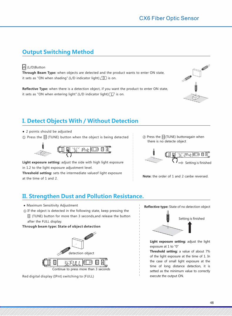
(NPN) (PNP)
Optic fiber accessories 72
38
20.5 20.5
13
147(When the protective cover is opened)
34
37
9
Max(170°)
5.15.15.1
27
5.3
22
10
4.3
L/D indicator light shows
ON/ (D) setting status with incoming
ON (L) shadowing
Light is on when OUT
indicator light
outputs to ON
(DPC indicator light)lights
up when the Dynamic power
control function is enabled
(St indicator light )
Light is on when smart
Tuning is executed
Sensitivity setting
(TUNE) Button to detect the object
Press the (ST) indicator light
once and at any time to turn
on the light
+ : Press simultaneously→:Press simultaneously in order
Setting initialization
Button locked
reset to 0
→
+
+
+
VII. Convenient Setting
Threshold fine-tuning
UP/Down button is greenOutput Switch Button(L/D)Press 1 time to switch ON(L) and ON(D) when the light is in and the indicator light is ON(L /D)
Light quantity adjustment(when the light quantity is saturated)
Setting
CX6 Series
BROWN
BLACK
BLUE
LOAD
+V
0VMain
Control Circuit
+V
0V
BROWN
BLACK
BLUE
LOAD
Input-Output Circuit Diagram
Main Control Circuit
Outline Dimensional Diagram
Mode toggle (MODE)
Press and hold for
more than3 seconds to
switch between the
set mode and the
detection mode
47
(L/D)Button
Through Beam Type: when objects are detected and the product wants to enter ON state,
it sets as "ON when shading".(L/D indicator light) is on.
Reflective Type: when there is a detection object, if you want the product to enter ON state,
it sets as "ON when entering light".(L/D indicator light) is on.
D
L
I. Detect Objects With / Without Detection
● 2 points should be adjusted
① Press the (TUNE) button when the object is being detected
Setting is finished
Note: the order of 1 and 2 canbe reversed.
Light exposure setting: adjust the side with high light exposure
in 1.2 to the light exposure adjustment level.
Threshold setting: sets the intermediate valueof light exposure
at the time of 1 and 2.
② Press the (TUNE) buttonagain when
there is no detecte object
Light exposure setting: adjust the light
exposure at 1 to "0"
Threshold setting: a value of about 7%
of the light exposure at the time of 1. In
the case of small light exposure at the
time of long distance detection, it is
setted as the minimum value to correctly
execute the output ON.
Continue to press more than 3 seconds
Red digital display (IPnt) switching to (FULL)
detection object
Setting is finished
II. Strengthen Dust and Pollution Resistance.
● Maximum Sensitivity Adjustment
① If the object is detected in the following state, keep pressing the
(TUNE) button for more than 3 seconds,and release the button
after the FULL display.
Through beam type: State of object detection
Reflective type: State of no detection object
Output Switching Method
48
CX6 Fiber Optic Sensor
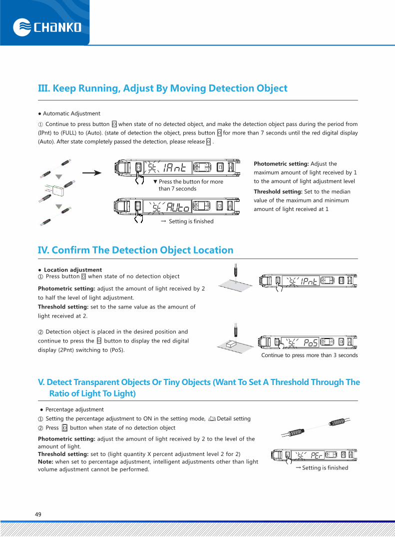
▼ Press the button for more
than 7 seconds
→ Setting is finished
→
III. Keep Running, Adjust By Moving Detection Object
● Automatic Adjustment
① Continue to press button when state of no detected object, and make the detection object pass during the period from
(IPnt) to (FULL) to (Auto). (state of detection the object, press button for more than 7 seconds until the red digital display
(Auto). After state completely passed the detection, please release .
Photometric setting: Adjust the
maximum amount of light received by 1
to the amount of light adjustment level
Threshold setting: Set to the median
value of the maximum and minimum
amount of light received at 1
IV. Confirm The Detection Object Location
Continue to press more than 3 seconds
● Location adjustment① Press button when state of no detection object
Photometric setting: adjust the amount of light received by 2
to half the level of light adjustment.
Threshold setting: set to the same value as the amount of
light received at 2.
② Detection object is placed in the desired position and
continue to press the button to display the red digital
display (2Pnt) switching to (PoS).
● Percentage adjustment
① Setting the percentage adjustment to ON in the setting mode, Detail setting
② Press button when state of no detection object
→ Setting is finished
V. Detect Transparent Objects Or Tiny Objects (Want To Set A Threshold Through The
Ratio of Light To Light)
Photometric setting: adjust the amount of light received by 2 to the level of the
amount of light.
Threshold setting: set to (light quantity X percent adjustment level 2 for 2)
Note: when set to percentage adjustment, intelligent adjustments other than light
volume adjustment cannot be performed.
49
Error Name / Display / Reason
● Intelligent Adjustment Error
Near Error
Difference between theamountof light receivedat point 1 and point 2
Over Error
Low Error
Type of
AdjustmentStrategy
2-point Automatic Adjustment And
Positioning Adjustment
Note: The adjustment range of the intelligent adjustment is about 20-1/100 times. When the detection function is selected as
GIGA mode, the range of adjustment is about 2 ~ 1 / 100 times because the initial value is large.
To change the level of light volume, browse for“VIII. Detail Setting”
Too much photometric
Too little photometric
All
Beyond
Maximum
Sensitivity
Adjustment
■ Please switch to a mode where the response time of the detection feature is slower■ Please narrow the gap between the cast and receive light. (Through Beam Type)■ Please bring the sensor close to the workpiece. (Reflective Type)
■ Please increase the level of light quantity adjustment.■ Please use a small-diameter fiber.■ Please expand the distance between the light and light. (Through Beam Type)Please keep the sensor away from the workpiece. (Reflective Type)
■ Please reduce the level of the amount of light adjustment.■ Please narrow the gap between the cast and receive light. (Through Beam Type)■ Please bring the sensor close to the workpiece. (Reflective Type)
① (UP/DOWN)Button setting.
Note: continuous push button for high speed adjustment
Threshold increase
VI. Threshold Fine-Tuning
Threshold decrease
VII. Convenient Setting
1.Want to restore light changes caused by dust or dirt
● Light volume adjustment
① When state of no detection object, press button and
button(MODE)continuously for more than 1 second
Photometric setting: Adjust the photometric received at time 1 to adjust the
level of light volume
Threshold setting: Will not change, the threshold is small, the output will be
set to perform the ON/OFF minimum correctly
Note: when reflective, perform in the presence of artifacts.
If the location adjustment has been performed, then the through beam and
reflective type should be executed in the presence of the detection object.Continue to press more than 1 sec → setting is finished
50
CX6 Fiber Optic Sensor
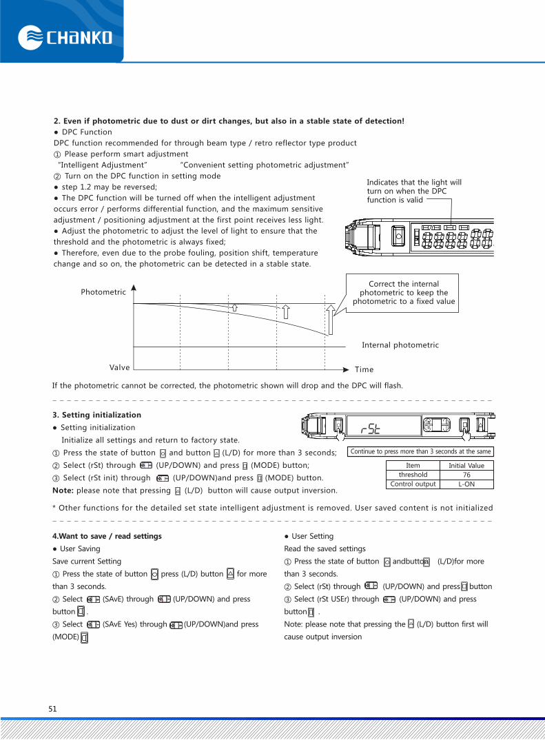
Valve
Correct the internal photometric to keep the
photometric to a fixed value
Internal photometric
Time
2. Even if photometric due to dust or dirt changes, but also in a stable state of detection!
● DPC Function
DPC function recommended for through beam type / retro reflector type product
① Please perform smart adjustment
“Intelligent Adjustment” “Convenient setting photometric adjustment”
② Turn on the DPC function in setting mode
● step 1.2 may be reversed;
● The DPC function will be turned off when the intelligent adjustment
occurs error / performs differential function, and the maximum sensitive
adjustment / positioning adjustment at the first point receives less light.
● Adjust the photometric to adjust the level of light to ensure that the
threshold and the photometric is always fixed;
● Therefore, even due to the probe fouling, position shift, temperature
change and so on, the photometric can be detected in a stable state.
Photometric
If the photometric cannot be corrected, the photometric shown will drop and the DPC will flash.
Indicates that the light willturn on when the DPCfunction is valid
3. Setting initialization
● Setting initialization
Initialize all settings and return to factory state.
① Press the state of button and button (L/D) for more than 3 seconds;
② Select (rSt) through (UP/DOWN) and press (MODE) button;
③ Select (rSt init) through (UP/DOWN)and press (MODE) button.
Note: please note that pressing (L/D) button will cause output inversion.
* Other functions for the detailed set state intelligent adjustment is removed. User saved content is not initialized
Continue to press more than 3 seconds at the same
Item
threshold
Control output
Initial Value
76
L-ON
4.Want to save / read settings
● User Saving
Save current Setting
① Press the state of button press (L/D) button for more
than 3 seconds.
② Select (SAvE) through (UP/DOWN) and press
button .
③ Select (SAvE Yes) through (UP/DOWN)and press
(MODE)
● User Setting
Read the saved settings
① Press the state of button andbutton (L/D)for more
than 3 seconds.
② Select (rSt) through (UP/DOWN) and press button
③ Select (rSt USEr) through (UP/DOWN) and press
button .
Note: please note that pressing the (L/D) button first will
cause output inversion
51
A
(b)
(c)
(d)
(a)
5. Prevent misoperation!
● Button locked
Turn off all button operation functions and press the button to display(Loc) on
■ Execute / release (same step)
■ Execute ■ Relieve
Hold for more than 3 seconds at the same time
6. Make the photometic displayed as 0!
● Return to zero reset
Displays the photometic received as 0 and the threshold changes accordingly.
Hold for more than 3 seconds at the same time
Note: After performing the DPC function / differential function adjustment, the reset is removed after returning to zero
Hold for more than 3 seconds at the same time
* Please press any key of UP/DOWN
VIII. Detailed Settings
Function Setting
1.FS
2.Detection Mode
Change the photometic and response time
Detection Function
HS high speed mode
STND Standard mode
GIGA High precision mode
(a)
(b)
(c)
(d)
300μs
2ms
16ms
100μs
150μs
1(benchmark)
1Times
12Times
0.25TimesNPN
PNP
Function Instruction
Continue press (MODE) button for more than 3 seconds to switch to
● Setting mode
In setting mode, the following functions can be setted
■ The content displayed on the function migration is the factory setting
When changing function setting in setting mode
Function setting 1 / 5
Function setting 1 / 10
Response Time Light Volume
After you change the mode of the detection feature, the
intelligent adjustment is removed.
*When switching detection mode to SHS, the communication
function prevents related interference from
Note: DPC function is to correct the automatic compensation
of the photometic received, used in CX6-DN10
SHS Ultra-high speed
52
CX6 Fiber Optic Sensor
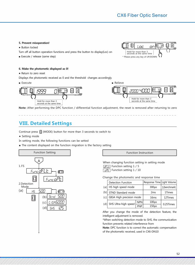
Valve
Correct the internal photometric to keep the
photometric to a fixed value
Internal photometric
Time
2. Even if photometric due to dust or dirt changes, but also in a stable state of detection!
● DPC Function
DPC function recommended for through beam type / retro reflector type product
① Please perform smart adjustment
“Intelligent Adjustment” “Convenient setting photometric adjustment”
② Turn on the DPC function in setting mode
● step 1.2 may be reversed;
● The DPC function will be turned off when the intelligent adjustment
occurs error / performs differential function, and the maximum sensitive
adjustment / positioning adjustment at the first point receives less light.
● Adjust the photometric to adjust the level of light to ensure that the
threshold and the photometric is always fixed;
● Therefore, even due to the probe fouling, position shift, temperature
change and so on, the photometric can be detected in a stable state.
Photometric
If the photometric cannot be corrected, the photometric shown will drop and the DPC will flash.
Indicates that the light willturn on when the DPCfunction is valid
3. Setting initialization
● Setting initialization
Initialize all settings and return to factory state.
① Press the state of button and button (L/D) for more than 3 seconds;
② Select (rSt) through (UP/DOWN) and press (MODE) button;
③ Select (rSt init) through (UP/DOWN)and press (MODE) button.
Note: please note that pressing (L/D) button will cause output inversion.
* Other functions for the detailed set state intelligent adjustment is removed. User saved content is not initialized
Continue to press more than 3 seconds at the same
Item
threshold
Control output
Initial Value
76
L-ON
4.Want to save / read settings
● User Saving
Save current Setting
① Press the state of button press (L/D) button for more
than 3 seconds.
② Select (SAvE) through (UP/DOWN) and press
button .
③ Select (SAvE Yes) through (UP/DOWN)and press
(MODE)
● User Setting
Read the saved settings
① Press the state of button andbutton (L/D)for more
than 3 seconds.
② Select (rSt) through (UP/DOWN) and press button
③ Select (rSt USEr) through (UP/DOWN) and press
button .
Note: please note that pressing the (L/D) button first will
cause output inversion
51
A
(b)
(c)
(d)
(a)
5. Prevent misoperation!
● Button locked
Turn off all button operation functions and press the button to display(Loc) on
■ Execute / release (same step)
■ Execute ■ Relieve
Hold for more than 3 seconds at the same time
6. Make the photometic displayed as 0!
● Return to zero reset
Displays the photometic received as 0 and the threshold changes accordingly.
Hold for more than 3 seconds at the same time
Note: After performing the DPC function / differential function adjustment, the reset is removed after returning to zero
Hold for more than 3 seconds at the same time
* Please press any key of UP/DOWN
VIII. Detailed Settings
Function Setting
1.FS
2.Detection Mode
Change the photometic and response time
Detection Function
HS high speed mode
STND Standard mode
GIGA High precision mode
(a)
(b)
(c)
(d)
300μs
2ms
16ms
100μs
150μs
1(benchmark)
1Times
12Times
0.25TimesNPN
PNP
Function Instruction
Continue press (MODE) button for more than 3 seconds to switch to
● Setting mode
In setting mode, the following functions can be setted
■ The content displayed on the function migration is the factory setting
When changing function setting in setting mode
Function setting 1 / 5
Function setting 1 / 10
Response Time Light Volume
After you change the mode of the detection feature, the
intelligent adjustment is removed.
*When switching detection mode to SHS, the communication
function prevents related interference from
Note: DPC function is to correct the automatic compensation
of the photometic received, used in CX6-DN10
SHS Ultra-high speed
52
CX6 Fiber Optic Sensor

(b)
A
(a)
(b)
(c)
(a)
(b)
(c)
T
TL-ON
ONOFF
D-ON ONOFF
T
TL-ON
ONOFF
D-ON ONOFF
T
TL-ON
ONOFF
D-ON ONOFF
3.DPC Function
When setting the timing time for the output
4.TimingFunction
●On the Settings ("---") menu, press you can pass
to set the timing. (1-9999ms.1MS scale, initial value
10ms)
5. Light volume
adjustment level
Choosing
[ ]
Choosing[ ]6. Percentage
Adjustment
Entering LightWhen the OFF delay timing detection time is short and the detection cannot be performed through PLC, the state of output ON is maintained.
● If you want to modify the target value of the amount
of light (light level adjustment) through to set the
amount of light adjustment level (100x9999,1 scale,
initial value 9999)
VII. Convenient Setting
ON delay timing detects the state of the delayed output ON.
Trigger timing even if the size of the object detected uneven, can also timing output.
Shading Time
● To detect transparent objects or tiny objects, click on
the (PEr On) menu After the (MODE) button, you can
pass the Button to change the percentage adjustment
level. (- 99% / 99% scale, initial value-10%)
Intelligent adjustment
Function Setting Function Instruction
Entering LightShading Time
Entering LightShading Time
53
7.DifferentialFunction
Differential setting
If the response time is greater than the threshold value, the
detection will be performed. The change in the photometic
received in the set response time is shown in red digital
display.
Response speed
● You can set the response time through the button. When
the differential function is valid, the detection function
setting is invalid.
●Intelligent adjustments other than light volume
adjustments cannot be performed. The adjustment range
of light volume 1~1/100 times.
1 2 3 4 5
250μs 500μs 1ms 10ms 100ms
(a)
(b)
(c)
(d)
(e)
A
(a)
(b)
(c)
(d)
(e)
8.Digital Display
9.Reverse Display
10.Power Saving
Function InstructionFunction Setting
Switching digital display when in detection mode
according to different purpose
When view the threshold value photometric percentage
When set threshold value photometric through a tiny detection object or a fast moving detection object
When perform an easy-to-visualize display in a simulated manner
When you want to perform an optical axis adjustment
The ch NO. at the link
When set the amplifier in reverse
● Reverse display
The threshold value displays as red number, photometric displays as
green number. Wants to cut power consumption
● Low Eco ON
Indicator light green (green digital red digital) lights out, through
the button operation, about 10 minutes after the lights will be lights
out
● Low Eco LO
After the operation of the button, the light will be on for about 10
seconds, and then the indicator light (green, red) will enter the state
of low light
Note: DPC function is to correct the automatic compensation of
the amount of light received, used in CX6-DN20
(a)
threshold value photometricpercentage
Threshold value photometric
percentage displays as red number
(b)
Peak value photometric
Valley value photometric Maintain and display the minimum of the
incoming peak value and the maximum
of the shading valley value
(c)
120%
100% 80%Displays current values with 100% threshold and 80%~120% display range
Threshold
(d)Peak value photometric Maintain the photometric received at the
peak and display as green number.
(e)
ch NO. photometic Displays the ch number and the amount of light
54
CX6 Fiber Optic Sensor
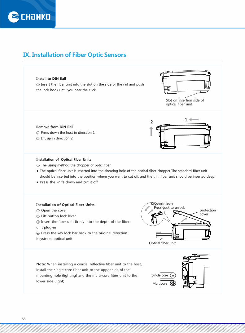
12
Slot on insertion side of optical fiber unit
Install to DIN Rail
① Insert the fiber unit into the slot on the side of the rail and push
the lock hook until you hear the click
Installation of Optical Fiber Units
① The using method the chopper of optic fiber
● The optical fiber unit is inserted into the shearing hole of the optical fiber chopper;The standard fiber unit
should be inserted into the position where you want to cut off, and the thin fiber unit should be inserted deep.
● Press the knife down and cut it off.
Installation of Optical Fiber Units
① Open the cover
② Lift button lock lever
③ Insert the fiber unit firmly into the depth of the fiber
unit plug-in
④ Press the key lock bar back to the original direction.
Keystroke optical unit
Note: When installing a coaxial reflective fiber unit to the host,
install the single core fiber unit to the upper side of the
mounting hole (lighting) and the multi-core fiber unit to the
lower side (light)
Keystroke lever Press Lock to unlock
protection cover
Optical fiber unit
Single core
Multicore
IX. Installation of Fiber Optic Sensors
Remove from DIN Rail
① Press down the host in direction 1
② Lift up in direction 2
55
EEPROM Error
Lock ON
Current Over
DPC Error
Error Name Reason
Photometric decrease
bacause of dust
or dirt.
Read / write
internal data
failed
Button locked
to open state
Control overload
current of output
Strategy
Please wipe the inspection surface of the optical fiber
unit, etc.and re-perform the intelligent adjustment after
restoring the photometic.
“Intelligent adjustment”
Please reconnect the power. If not restored, perform
initialization operation
“ VII. Convenient Setting”
Please confirm the load of the control output and set
it in the rated range. Please confirm if the load is short
circuit
"Output input circuit diagram, rating / specification"
XI. Maintenance (Troubleshooting)
Fault
Blank on screen
Nothing is displayed
on the digital display
Cannot be checked or detected even if thethreshold value is minimum
Photometric display
variation
Action indicator blinking
The amount of
light is displayed
as-(negative)
Set unknown
Reason
Affected by dust or dirt and
temperature changing
The state of power off,
or disconnected
Power saving is ON state
The detection function has been setting to a small photometic mode and is affected by dust or dirt
Be affected by mutual
interference, etc.
Zero reset is open state
Differential function is open state
Strategy
Please check wiring, power supply voltage, and power supply capacity "output input circuit diagram"
X. Error Indication
Please unlock the key
“ VII. Convenient Setting”
Please turn off the environment protection function
When set to GIGA mode, the photometic increases
and the amount of light displayed increases
If you use the DPC function, the photometric display
can be stabilized
Please unreset the return to zero"VII. Convenient Setting"
Please turn off the differential function
Please perform the set initialization operation
"VII. Convenient Settings"
"VIII. Detail Setting"
"VII. Convenient Setting"
"VIII. Detail Setting"
"VIII. Detail Setting"
Please confirm the connection status of the sensor and power it up again
"IX. Installation of Fiber Optic Sensors"
56
CX6 Fiber Optic Sensor
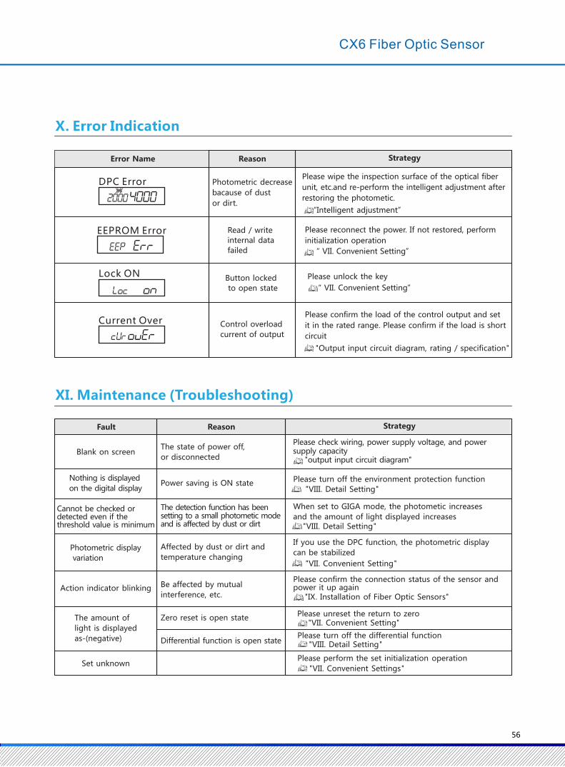
12
Slot on insertion side of optical fiber unit
Install to DIN Rail
① Insert the fiber unit into the slot on the side of the rail and push
the lock hook until you hear the click
Installation of Optical Fiber Units
① The using method the chopper of optic fiber
● The optical fiber unit is inserted into the shearing hole of the optical fiber chopper;The standard fiber unit
should be inserted into the position where you want to cut off, and the thin fiber unit should be inserted deep.
● Press the knife down and cut it off.
Installation of Optical Fiber Units
① Open the cover
② Lift button lock lever
③ Insert the fiber unit firmly into the depth of the fiber
unit plug-in
④ Press the key lock bar back to the original direction.
Keystroke optical unit
Note: When installing a coaxial reflective fiber unit to the host,
install the single core fiber unit to the upper side of the
mounting hole (lighting) and the multi-core fiber unit to the
lower side (light)
Keystroke lever Press Lock to unlock
protection cover
Optical fiber unit
Single core
Multicore
IX. Installation of Fiber Optic Sensors
Remove from DIN Rail
① Press down the host in direction 1
② Lift up in direction 2
55
EEPROM Error
Lock ON
Current Over
DPC Error
Error Name Reason
Photometric decrease
bacause of dust
or dirt.
Read / write
internal data
failed
Button locked
to open state
Control overload
current of output
Strategy
Please wipe the inspection surface of the optical fiber
unit, etc.and re-perform the intelligent adjustment after
restoring the photometic.
“Intelligent adjustment”
Please reconnect the power. If not restored, perform
initialization operation
“ VII. Convenient Setting”
Please confirm the load of the control output and set
it in the rated range. Please confirm if the load is short
circuit
"Output input circuit diagram, rating / specification"
XI. Maintenance (Troubleshooting)
Fault
Blank on screen
Nothing is displayed
on the digital display
Cannot be checked or detected even if thethreshold value is minimum
Photometric display
variation
Action indicator blinking
The amount of
light is displayed
as-(negative)
Set unknown
Reason
Affected by dust or dirt and
temperature changing
The state of power off,
or disconnected
Power saving is ON state
The detection function has been setting to a small photometic mode and is affected by dust or dirt
Be affected by mutual
interference, etc.
Zero reset is open state
Differential function is open state
Strategy
Please check wiring, power supply voltage, and power supply capacity "output input circuit diagram"
X. Error Indication
Please unlock the key
“ VII. Convenient Setting”
Please turn off the environment protection function
When set to GIGA mode, the photometic increases
and the amount of light displayed increases
If you use the DPC function, the photometric display
can be stabilized
Please unreset the return to zero"VII. Convenient Setting"
Please turn off the differential function
Please perform the set initialization operation
"VII. Convenient Settings"
"VIII. Detail Setting"
"VII. Convenient Setting"
"VIII. Detail Setting"
"VIII. Detail Setting"
Please confirm the connection status of the sensor and power it up again
"IX. Installation of Fiber Optic Sensors"
56
CX6 Fiber Optic Sensor
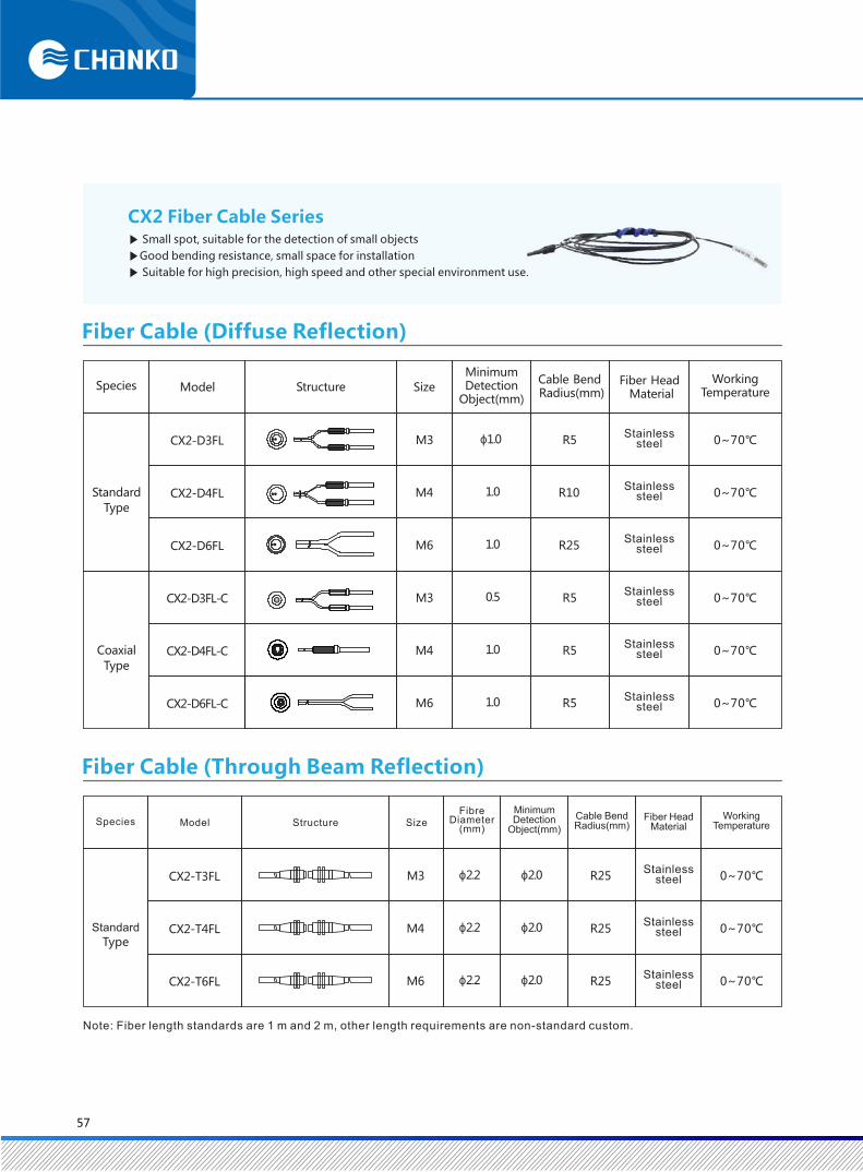
CX2-D3FL
CX2-D4FL
CX2-D6FL
CX2-D3FL-C
CX2-D4FL-C
CX2-D6FL-C
M3
M4
M6
M3
M4
M6
ɸ1.0
1.0
1.0
0.5
1.0
1.0
R5
R10
R25
R5
R5
R5
0~70℃
0~70℃
0~70℃
0~70℃
0~70℃
0~70℃
CX2-T3FL
CX2-T4FL
CX2-T6FL
M3
M4
M6
ɸ2.2
ɸ2.2
ɸ2.2
R25
R25
R25
0~70℃
0~70℃
0~70℃
ɸ2.0
ɸ2.0
ɸ2.0
CX2 Fiber Cable Series▶ Small spot, suitable for the detection of small objects
▶Good bending resistance, small space for installation
▶ Suitable for high precision, high speed and other special environment use.
Species
Standard
Type
Coaxial
Type
Model Structure Size
MinimumDetection
Object(mm)
Cable Bend Radius(mm)
Fiber Head Material
WorkingTemperature
Stainless steel
Stainless steel
Stainless steel
Stainless steel
Stainless steel
Stainless steel
Species
Standard
Type
Model Structure SizeFibre
Diameter(mm)
Minimum Detection
Object(mm)
Cable Bend Radius(mm)
Fiber Head Material
Working Temperature
Stainless steel
Stainless steel
Stainless steel
Note: Fiber length standards are 1 m and 2 m, other length requirements are non-standard custom.
Fiber Cable (Through Beam Reflection)
Fiber Cable (Diffuse Reflection)
57
● Size Specification of Diffuse Reflection (Standard) Fiber Cable
CX2-D3FL CX2-D4FL CX2-D6FL
● Size Specification of Diffuse Reflection (Coaxial) Fiber Cable
CX2-D3FL-C CX2-D4FL-C CX2-D6FL-C
● Size Specification of Through Beam Reflection (Standard) Fiber Cable
CX2-T3FL CX2-T4FL CX2-T6FL
1000/2000
Φ2.2
40
Ratio:5:1
17
Φ0.5*2
Φ3.6Φ1
11
12 5
1.5
0.5
5.5
1000
Φ2.2
1040
Φ0.5*2
Φ3.6Φ1M2.5 P0.45
1711
M4 P0.77
523
1000/2000
Φ2.2
40Φ1*2
M6 P0.75
3
14
2.5
Φ3.8
10
13
1000
Φ2.2
23
Φ0.25*16
Φ3.8 Φ5M6 P0.7510
2.53
5
1000
Φ2.2
2Φ0.25*9
M2.5 Φ3.6Φ1
11 17
M4 P0.7
40
13.5
12
7
1000/2000
Φ2.2Φ4
14
M6 P0.7510
1
2.5
40
3
3
Φ11000
Φ2.2Φ2.5
13
Φ1
M4 P0.77
10
2
40
3
1000/2000
Φ2.2Φ2
12Φ1
M3 P0.55.5
1.5 40
5
0.5
Φ1.3 Φ3.6 Φ2.2M3 P0.5
1000/2000
11 1740
19 5
1.5
5.5
ECOTTER TGRC-M310
Outline Dimensional Diagram
M3 P0.5 Flexible tubeRatio:5:1 Flexible tube
Ratio:4:1
Flexible tube
Outside Φ0.25*9Lnside Φ0.5*1
Ratio:5:1
Flexible tubeRatio:3:1 Flexible tube
Ratio:3:1
Ratio:5:1
Flexible tubeRatio:3:1
Flexible tube Ratio:3:1
Flexible tube
CX2 Fiber Cable Series
58

Our products are widely used in semiconductor, packaging machinery, printing machinery,
pharmaceutical machinery, plastic machinery, lithium battery equipment, solar equipment,
agricultural machinery, etc.
Industry Application Case
Test whether the product is available or not Detect if there is a gap on the edge of the glass
Heck whether the capacitor leads are available Diffuse cursor detection
Detect if the edges of the glass are flat Detect the position of the two polar ends of the battery
Detect if the box on the conveyor belt is interrupted Check if the wire of the winding machine is used up.
59