
For more information on Kingspan Insulation visit …...2.3.2 Testing for Air Leakage Testing of...
16
INDUSTRIAL INSULATION ® Kingspan, KoolDuct and the Lion Device are Registered Trademarks of the Kingspan Group of Companies Kingspan Industrial Insulation Limited PO Box 3, Charlestown, Glossop, Derbyshire, SK13 8LE, UK Telephone: +44 (0) 1457 861611 Fax: +44 (0) 1457 852319 email: [email protected] Castleblayney, County Monaghan, Ireland Telephone: +353 (0) 42 9795000 Fax: +353 (0) 42 9746129 email: [email protected] For further information on the KoolDuct System please telephone the Kingspan Technical Services Department on 01457 861611 (UK) or 042 9795000 (Ireland) Whilst the information contained in this brochure is true and accurate to the best of our knowledge and belief, all liability for errors and omissions, damage or loss resulting herefrom is hereby excluded. Recommendations for use should be verified as to suitability and compliance with actual requirements, specifications and any applicable laws and regulations. The values given against these properties are typical. They are not meant to imply specification limits and should not be used for this purpose without reference to Kingspan Industrial Insulation. This brochure cancels and supersedes all previous editions. Kingspan Industrial Insulation reserves the right to amend specifications without prior notice. www.kooltherm.kingspan.com For more information on Kingspan Insulation visit www.barbourproductsearch.info
Transcript of For more information on Kingspan Insulation visit …...2.3.2 Testing for Air Leakage Testing of...

INDUSTRIAL INSULATION
® Kingspan, KoolDuct and the Lion Device are Registered Trademarks of the Kingspan Group of Companies
Kingspan Industrial Insulation LimitedPO Box 3, Charlestown, Glossop, Derbyshire, SK13 8LE, UK
Telephone: +44 (0) 1457 861611 Fax: +44 (0) 1457 852319email: [email protected]
Castleblayney, County Monaghan, IrelandTelephone: +353 (0) 42 9795000 Fax: +353 (0) 42 9746129
email: [email protected]
For further information on theKoolDuct System please telephone the
Kingspan Technical Services Department on 01457 861611 (UK)
or 042 9795000 (Ireland)
Whilst the information contained in this brochureis true and accurate to the best of our knowledgeand belief, all liability for errors and omissions,damage or loss resulting herefrom is herebyexcluded. Recommendations for use should beverified as to suitability and compliance withactual requirements, specifications and anyapplicable laws and regulations.
The values given against these properties aretypical. They are not meant to implyspecification limits and should not be used forthis purpose without reference to KingspanIndustrial Insulation.
This brochure cancels and supersedes allprevious editions. Kingspan Industrial Insulationreserves the right to amend specifications withoutprior notice.
www.kooltherm.kingspan.com
For more information on Kingspan Insulation visit www.barbourproductsearch.info

INDUSTRIAL INSULATION
THE
KOOLDUCT SYSTEM
DESIGN GUIDE
CI/SfB(5-) In7 (M2)
April 2000
…… No Worries
For more information on Kingspan Insulation visit www.barbourproductsearch.info

2
The KoolDuct System Design Guide
Page
1 KoolDuct Complete System Technology 3
2 The KoolDuct System – Design Theory
2.1 Application Limitations 4
2.2 Pressure Classification 5
2.3 Air Leakage Standards 6
2.4 Economy of Duct Design 7
3 The KoolDuct System – Practical Design Guide
3.1 Fabrication of Ductwork 8
3.2 Rectangular Ducts 10
3.3 Elbows 13
3.4 Reducers 16
3.5 Offsets 18
3.6 Take-offs 19
3.7 Duct Reinforcement 21
3.8 Dual Duct Design 23
3.9 Access Openings 24
3.10 Aluminium Flange Usage 25
3.11 Plant and Component Connection 28
3.12 Duct Support and Hangers 28
3.13 Protective Treatment and Painting 30
3.14 Damage Repair 31
CONTENTS
For more information on Kingspan Insulation visit www.barbourproductsearch.info

3
1 KOOLDUCT COMPLETE SYSTEMTECHNOLOGY
The Heating, Ventilation, and Air Conditioning(HVAC) industry is in the midst of a dynamic era.However, air ducting, a critical component ofHVAC systems, has remained virtuallyunchanged since the early 1900’s. Severalfactors and recent innovations have introducedthe need to revolutionise air ducting. Buildingmaterials and insulating products havedramatically improved. Requirements for cleanair are becoming increasingly stringent. Energycosts have continued to escalate. Changing fireand smoke regulations have raised the standardsfor compliance.
Kingspan Industrial Insulation is pleased topresent a revolutionary approach to insulatedductwork. The KoolDuct System is like no otherinsulated ducting. It is the most advanced andinnovative System of pre-insulated air distributionductwork available in the UK and Ireland.The KoolDuct System of pre-insulated ducting isa proven, easy, innovative product providing anew perspective in the field of air distribution.
This third generation System virtually eliminatesall the problems of traditional metal ductworkwhile at the same time offering extra advantagesto both the consulting engineer and thefabricator/installer. The System is the clearleader in the new generation of insulatedprefabricated ducting and has already proveditself in the highly competitive globalmarketplace.
What’s different about the KoolDuct System.Traditionally, ducting is made of sheet metalwhich is installed first and then lagged withinsulation as a second operation. The KoolDuctSystem offers pre-insulated ducting withaluminium surfaces in a single fix.
The KoolDuct System comprises duct sectionsfabricated from phenolic insulation panels andjoined together with proprietary jointing systems.
For more information on Kingspan Insulation visit www.barbourproductsearch.info
The KoolDuct System Design Guide
2 THE KOOLDUCT SYSTEM– DESIGN THEORY
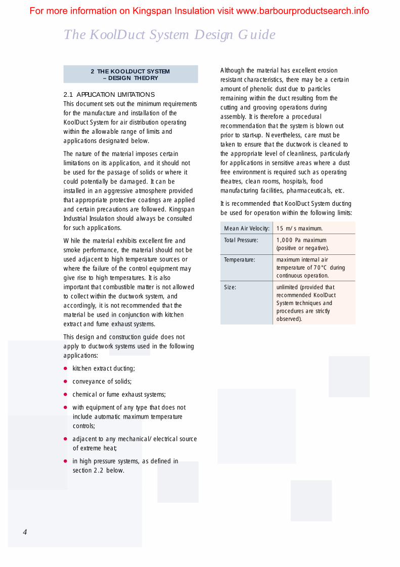
2.1 APPLICATION LIMITATIONSThis document sets out the minimum requirementsfor the manufacture and installation of theKoolDuct System for air distribution operatingwithin the allowable range of limits andapplications designated below.
The nature of the material imposes certainlimitations on its application, and it should notbe used for the passage of solids or where itcould potentially be damaged. It can beinstalled in an aggressive atmosphere providedthat appropriate protective coatings are appliedand certain precautions are followed. KingspanIndustrial Insulation should always be consultedfor such applications.
While the material exhibits excellent fire andsmoke performance, the material should not beused adjacent to high temperature sources orwhere the failure of the control equipment maygive rise to high temperatures. It is alsoimportant that combustible matter is not allowedto collect within the ductwork system, andaccordingly, it is not recommended that thematerial be used in conjunction with kitchenextract and fume exhaust systems.
This design and construction guide does notapply to ductwork systems used in the followingapplications:
kitchen extract ducting;
conveyance of solids;
chemical or fume exhaust systems;
with equipment of any type that does notinclude automatic maximum temperaturecontrols;
adjacent to any mechanical/electrical sourceof extreme heat;
in high pressure systems, as defined insection 2.2 below.
Although the material has excellent erosionresistant characteristics, there may be a certainamount of phenolic dust due to particlesremaining within the duct resulting from thecutting and grooving operations duringassembly. It is therefore a proceduralrecommendation that the system is blown outprior to start-up. Nevertheless, care must betaken to ensure that the ductwork is cleaned tothe appropriate level of cleanliness, particularlyfor applications in sensitive areas where a dustfree environment is required such as operatingtheatres, clean rooms, hospitals, foodmanufacturing facilities, pharmaceuticals, etc.
It is recommended that KoolDuct System ductingbe used for operation within the following limits:
Mean Air Velocity: 15 m/s maximum.
Total Pressure: 1,000 Pa maximum(positive or negative).
Temperature: maximum internal airtemperature of 70°C duringcontinuous operation.
Size: unlimited (provided thatrecommended KoolDuctSystem techniques andprocedures are strictlyobserved).
4
For more information on Kingspan Insulation visit www.barbourproductsearch.info

5
2.2 PRESSURE CLASSIFICATIONPressure, rather than velocity, is the main basisfor classification for the lower velocity ductworksystems for which the KoolDuct System isrecommended. Air leakage and phenolicinsulation panel deflection for low velocitysystems are almost entirely a function of pressure(static pressure), and not velocity (dynamicpressure). It is therefore common practice in theHVAC industry to approximate static pressure astotal pressure, and ignore the relatively minorcontribution of dynamic pressure for this class ofductwork. This specification is based on thepressure classes set out in Table 2.2.1.
Duct Static Static Mean Air AirPressure Pressure Pressure Velocity LeakageClass Limit (Pa) Limit (Pa) (Maximum)
Positive Negative (m/s)
Low 500 500 10 Class A
Medium 1,000 750 15 Class B
High 2,000 750 20 Class C
Table 2.2.1
Note that ‘mean air velocity’ refers to the design air flowrate related to the cross sectional area of the ductwork. Also, ductwork pressure relates to the actual static pressureof the relevant section of ductwork, and not the fan staticpressure.
For more information on Kingspan Insulation visit www.barbourproductsearch.info

The KoolDuct System Design Guide
2.3 AIR LEAKAGE STANDARDSThe permitted air leakage limit for each standardof air-tightness, as defined by DW 144, is setout in Table 2.3.1 below:
Duct Pressure Air Leakage Leakage LimitClass Requirement (litre/sec/m2*)
Low Class A 0.027 x p0.65**
Medium Class B 0.009 x p0.65**
High Class C 0.003 x p0.65**
Table 2-3-1
* surface area computed based internal duct dimensions** p is the pressure differential in Pascals
As can be seen from Table 2.3.1, the higher theduct pressure class, the more stringent theleakage limits. Therefore, when classifyingductwork, economic advantage can be attainedby matching the duct pressure classification tothe duct distribution static pressure. For example,in certain installations where the supply ductworkis designated as Class B, the terminal outletsmight possibly be classified as Class A.
2.3.1 Leakage at Various PressuresBased on the limits set out in Table 2.3.1, themaximum allowable air leakage for each pressureclass over a range of pressures from 0 to 2,000Pascals is plotted in Figure 2.3.1. The leakagefigures are given in litres of air per second persquare metre of internally measured ductworkagainst a static pressure differential ranging from100 Pa to 2,000 Pa.
6
2.3.2 Testing for Air LeakageTesting of ductwork to establish conformity with theleakage limits specified in Table 2.3.1 is generallyonly required for high pressure applications (i.e.,Class C). Therefore, testing for air leakage ofductwork operating within low and medium rangesof pressure is not necessary unless explicitly calledfor in the job specification.
1.8
Max
imum
Allo
wab
le L
eaka
ge
Static Pressure Differential (Pa)
1.61.41.21.00.80.60.40.2
0
100
200
300
400
500
600
700
800
900
1000
1100
1200
1300
1400
1500
1600
1700
1800
1900
2000
0
Class A
Class CClass B
Figure 2.3.1Allowable Leakage Per Pressure Class
Notes:leakage expressed in litre per second per square metre;pressure expressed in Pascals (Pa);low pressure region defined as 0-500 Pa;medium pressure region defined as 500-1,000 Pa;high pressure region defined as above 1,000 Pa.
For more information on Kingspan Insulation visit www.barbourproductsearch.info

7
2.4 ECONOMY OF DUCT DESIGNAlthough the same general design rules apply as to sheet metal ductwork, it is important torecognise that the user should be aware of theneed to plan optimum material usage in order toachieve economy of fabrication. Off-cuts havelittle or no scrap value.
The ductwork system comprises a substantialportion of the overall cost of a buildings HVACsystem - potentially in excess of one-third of thetotal cost. Careful and attentive planning duringthe design stage of the ductwork system canyield significant reduction of the overall cost ofthe system. There are two factors in particularthat can have a considerable impact:
the total number of special pieces (piecesother than straight sections); and
the aspect ratio of the duct segments.
Special pieces such as elbows, reducers, andoffsets, etc. require considerably more labour(and material to a certain extent) to constructthan straight segments. While all ductworksystems will require a certain amount of specialfittings, their usage should be minimised. Ideally,the system should follow the straightest routepossible.
The other point which is less intuitively obvious isthe aspect ratio of the duct segments. This ratiois defined as the duct’s larger side divided by itssmaller side. As the aspect ratio increases, thecorresponding surface area dramaticallyincreases. Table 2.4.1 illustrates this relationshipfor six duct sizes of identical cross sectionalareas with different aspect areas. In addition,higher aspect ratio ducts also exhibit increasedfrictional resistance and noise. As can be seen,a square aspect ratio is the most economical(1:1). However, while smaller aspect ratios aremore desirable from a material requirements andaerodynamic standpoint, the trade-off is in spacerequirements, as small aspect ratio ducts requiremore clearance for installation. Based on all ofthese considerations, it is not recommended thataspect ratios exceed 4:1.
Aspect Ratio
40
30
20
10
0
50
% In
crea
se in
Sur
face
Are
a Re
quire
men
tO
ver S
quar
e A
spec
t Rat
io
1 2 3 4 5 6
Figure 2.4.1Duct Aspect Ratio
For more information on Kingspan Insulation visit www.barbourproductsearch.info

3 THE KOOLDUCT SYSTEM– PRACTICAL DESIGN GUIDE
3.1 FABRICATION OF DUCTWORKAll personnel responsible for the fabrication andconstruction of ductwork systems shall, prior tobeing engaged in the work, have successfullycompleted the specialised KoolDuct Systemtraining course and shall be familiar with allaspects of the fabrication techniques necessaryfor the manufacture of the complete system.All trainees who successfully complete thetraining course are awarded a KoolDuct Systemcertificate of competency.
The KoolDuct System offers a complete productline providing all tools, accessories andcomponents necessary to fabricate ductwork.Each item has been rigorously tested in thelaboratory and the field to the highest ofstandards in a variety of applications. Under nocircumstance are any substitute components tobe used in place of approved KoolDuct Systemproducts.
3.1.1 ProcedureThe construction of a duct is accomplished byfollowing a standardised procedure. The processis the same regardless of the shape of the ductelement:
tracing;
cutting;
gluing;
folding;
taping;
flanging & reinforcement; and
sealing.
Although each of the above operations isdescribed in general below, this design guide isby no means intended to serve as an instructionmanual to replace the training course. Note thatwhen properly constructed, the finished duct willhave no exposed phenolic insulation - internallyor externally.
3.1.2 TracingThe tracing of the duct outline onto the phenolicinsulation panel is the first step of the process.This is accomplished by utilising the Teflon“pencils” supplied in each tool box which scribea line as opposed to marking a line. Note thatall measurements specified on drawings of ductsystems refer to a duct’s internal dimension. Thiscorresponds to the cross-sectional area of the airpassage necessary to satisfy designrequirements. It is therefore recommended thatthe fabricator adopt the convention of internalmeasurements during plotting. Accordingly, alltracing and plotting will take place on theinternal side of the duct.
3.1.3 CuttingThis operation involves cutting 45° mitre cutsalong each edge of the duct. These ‘V’ groovesmade by the 45° Jack Plane enable the phenolicinsulation panel to be folded into shape. The ‘V’groove is also optimal for the subsequent gluingoperation as it provides maximum bondedsurface area. The material that is discarded as aresult of this operation must have beenaccounted for during the previous tracing.There are also several other special purposeJack Planes available including the 22.5°, andthe Adjustable.
3.1.4 GluingThe glue must be well shaken prior to use inorder to assure uniform consistency. Glue isapplied evenly to mitred surfaces utilising aPneumatic Glue Spreader, and should cover allexposed phenolic material. Note that the ‘V’groove should first be swept clean of anyremaining phenolic dust. Depending on thetemperature and relative humidity, the adhesiverequires approximately 10 to 20 minutes to cureduring which time the solvents evaporate. This operation should be performed in a wellventilated area and the precautionsrecommended on the COSHH datasheet sheetshould be observed. The curing period iscomplete when the glue is dry to the touch.
8
The KoolDuct System Design Guide
For more information on Kingspan Insulation visit www.barbourproductsearch.info

9
3.1.5 FoldingFollowing the curing phase, the sides are foldedat right angles to each other (90°) and the ductshape is formed. Note that when two opensides of a duct are joined together, thealuminium foil edge of the mitre cut on theinternal surface should be used for aligningpurposes. When a duct is comprised of severalindividual pieces, the joining process shouldalways be initiated from the same end so thatthe subsequent trimming operation of any excesslength is required at the opposite end only. The black hard spatulas should then be used tofirmly crease along the edges of the duct toensure maximum adhesion in the ‘V’ grooves.
3.1.6 TapingSpecial reinforced aluminium self adhesive tapeis provided. The tape has been double cured forincreased pliability, and contains 2.5 times asmuch glue as standard tapes to ensure maximumadhesion. The taping of the duct serves fourpurposes:
it re-establishes the vapour barrier within themitred cuts;
external seams are taped to improve theduct’s aesthetic appearance;
tape is used to repair and cover anydamage to the phenolic insulation panel,both externally and internally; and
it seals and isolates the phenolic materialfrom the surroundings.
Prior to applying the tape, ensure that allsurfaces are dry, and free of dirt, oil, silicone,and grease. If the surface can not be thoroughlycleaned, then a simple solution is to apply alight coat of glue on the surface where the tapeis to be placed (note that the glue must beallowed to cure first, as discussed within section3.1.4 above). The tape should ideally beapplied in temperatures above 10°C in order toassure a satisfactory bond. The tape should notbe applied to the duct’s surface when thetemperature is below 0°C due to the potentialentrapment of ice crystals.
Tape is only applied to seams where theexternal surface of the aluminium foil has beencut. On sides where the phenolic insulationpanel has been simply folded, as opposed tojoined, no tape is required. The tape-marker isused to scribe a line on the phenolic insulationpanel which serves as reference duringapplication of the tape. The soft spatula isbrushed firmly along the surface of the tapeduring application to ensure maximum adhesionand to expel any air trapped underneath.When taping reducers or elbows, the tape mustalways be applied to the curved or creasedsurface (not the flat surface), and thesupplemental directions within the respectivesections should be observed.
3.1.7 Aluminium Profile and ReinforcementThere are a variety of aluminium profilesavailable to suit various installation requirements.A full discussion of each, complete withinstruction, is provided in section 3.10.
Depending on both the system pressure and theduct’s dimensions, the installation of reinforcementbar may be necessary. Section 3.7 provides acomplete guide to its usage.
3.1.8 SealingFollowing assembly of the duct segment, allinternal joints must be sealed with silicone.In addition to imparting greater strength andrigidity, the primary function of the silicone is tohermetically seal the internal surface of the ductand prevent any phenolic particles from enteringthe air stream. It is recommended that after thesilicone bead has been applied, a radiused tool(or alternatively a wet finger) is gently run alongthe entire length of the bead to further spreadthe sealant along the sides of the duct wall.Proper application is crucial in order to achieve“clean air” performance and minimise leakage.
For more information on Kingspan Insulation visit www.barbourproductsearch.info

10
The KoolDuct System Design Guide
3.2 RECTANGULAR DUCTSFor purposes of clarity, the following conventionwill be adopted, where w refers to internal ductwidth, h refers to internal duct height, and lrefers to duct length:
Figure 3.2.1
KoolDuct System phenolic insulation panels aresupplied in one size only: 2,950 mm x 1,200mm x 22 mm. Ducts may be constructed bycutting ‘V’ grooves along the length or the widthof the phenolic insulation panel. The methods forcutting rectangular ducts are divided into fourgeneral classes, and the selection of theappropriate technique is governed by thedimensions of the duct. The correct choice willminimise both material usage and fabricationtime. Table 3.2.1 specifies the limitingdimensions of a duct for each method, andsections 3.2.1-3.2.4 describe the procedure.Dual Duct design is presented separately insection 3.8.
Duct Side Maximum LengthDimensions of Duct Segment
Method (mm) (metres)
1 2 x (w+h) <1040 2.95the sum of 4 sides
2a (h+w+h) <1080 2.95the sum of any 3 sides
2b (w+h) <1120 2.95the sum of 2 sides
2c w and h <1160 2.95any single side
3a, 3b (h+w+h) <2830 3.56the sum of any 3 sides
4 w and h <2910 1.2any single side
Dual unlimited 2.95Ducts see section 3.8
Figure 3.2.1Rectangular Straight Duct Construction
3.2.1 Rectangular Ducts – Method 1This method is utilised when the perimeter of aduct is less than or equal to 1,040 mm. The advantages are simplicity and strength inthat the entire duct can be constructed from asingle phenolic insulation panel. The figure of1,040 mm is derived from subtracting thecombined length of the off-cuts of the mitregrooves (equivalent to 20+40+40+40+20= 160 mm) from the phenolic insulation panelwidth: 1,200–160 = 1,040 mm. The ‘V’grooves are cut in the lengthways direction, andthe duct is constructed as shown below in Figure3.2.2. Aluminium flanges should be fitted onboth ends of the duct segment.
l
h
w
Figure 3.2.2
Method 1: w+h+w+h<1,040 mm
1,200 mm maximum
h w h w
For more information on Kingspan Insulation visit www.barbourproductsearch.info

11
Figure 3.2.5
Aluminium flanges should be fitted on both endsof the duct segment, for each of the methodscovered in Class 2 ducts.
3.2.3 Rectangular Ducts – Method 3This method is employed for larger ducts still. The ‘V’grooves are now cut along the widthways directionof the phenolic insulation panel which means thateach individual module is limited to 1,180 mm inlength (computed as the 1,200 mm phenolicinsulation panel width less the 20 mm mitre cut).
When constructing rectangular ducts utilising thethird family of techniques, it is permissible to joinup to three individual modules together withmale-female jointing alone, provided that thefollowing precautions are observed. First, thecover must be carefully positioned such that thejoints are staggered, thus adding an additionaldegree of strength and stability. The edge of thecover must never, under any circumstance, beallowed to coincide with the male-female jointsof the three duct modules.
In addition, the direction of the male-femalejoints must be consistent with the direction of theair flow. Figure 3.2.6 below demonstrates theproper application. All male-female joints mustbe glued and then taped on both sides. Finally,aluminium flanges shall not exceed 3.6 metres indistance apart (three duct modules) when usingthis method of construction.
Figure 3.2.3
If the duct is larger still, and the sum of two sidesis less than or equal to 1,120 mm, then method2b applies. In this case, the duct will beconstructed of two symmetrical pieces, eachconsisting of two full sides. The ‘V’ grooves areagain cut in the lengthways direction, and isillustrated in Figure 3.2.4.
Method 2b: w+h<1,120 mm
Figure 3.2.4
A larger duct can also be constructed by utilising anindividual phenolic insulation panel for each side ofthe duct, as prescribed by method 2c, illustrated inFigure 3.2.5. The side dimension of such a ductwould be limited to the size of the KoolDuct Systemphenolic insulation panel corrected for the mitrecuts, 1,160 mm (1,200 – 20 – 20). The length ofthe duct segment is again limited to the length ofthe phenolic insulation panel, 3 m.
3.2.2 Rectangular Ducts – Method 2This method is utilised for larger ducts that are still3 metres in length, but constructed of separatephenolic insulation panels that are subsequentlyjoined. The dimensions of the duct dictate whetheror not the individual pieces are symmetrical(method 2b), or asymmetrical (method 2a).
When the duct cannot be constructed accordingto Figure 3-2-2, and the sum of three of thesides is less than or equal to 1,080 mm, thenmethod 2a applies. The duct is constructed asillustrated in Figure 3-2-3 by using a U shapedpiece and a cover. The ‘V’ grooves are still cutin the lengthways direction.
Method 2a: w+h+w<1,080 mm
Method 2c: w and h<1,160 mm
1,200 mm maximum
h hw w
1,200 mm maximum1,200 mm maximum
h hw w
h hw w
2,950 mmmaximum
Figure 3.2.6
Direction of air fl
ow
1,200 mmmaximum
1,180 mmmaximum
1,180 mmmaximum
For more information on Kingspan Insulation visit www.barbourproductsearch.info

12
The KoolDuct System Design Guide
When the dimensions of the duct exceed the limitsset forth in the previous two classes, and the sumof three sides is less than or equal to 2,830 mm,then both methods 3a and 3b can be utilised. The determining factor for selecting the propertechnique is the width of the cover. If the coverwidth is less than or equal to 1,160 mm, thenmethod 3a applies, as shown in Figure 3.2.7.Note that the orientation of the cover is lengthways(2,950 mm) which would mean that asupplementary piece of roughly 630 mm in lengthwould be necessary to complete the cover for aduct that is composed of three modules (3.6 metreslong) as is the case in Figure 3.2.7.
Method 3a: w+h+w<1,080 mm• 3 U-shaped segments joined together using male/female• maximum combined length of 3.56 m (3 modules)• the sum of three sides equal to or
less than 2,830 mm (internally)• cover width equal to or
less than 1,160 mm (internally)
Figure 3.2.7
If the cover width exceeds 1,160 mm, then method3b would be applicable. The difference is that theorientation of the phenolic insulation panel stripsused for the cover is in the widthways direction.Accordingly, each are 1,200 mm long. Again,care should be taken to ensure that the seams of thecover do not coincide with the male-female joints ofthe duct body. Figure 3.2.8 provides an example.
Method 3b: w+h+w<1,080 mm• 3 U-shaped segments joined together using male/female• maximum combined length of 3.56 m (3 modules)• the sum of three sides equal to or
less than 2,830 mm (internally)• cover width equal to or
less than 1,160 mm (internally)
3.2.4 Rectangular Ducts – Method 4This method is reserved for the largest of ductsizes. The ‘V’ grooves are cut along the widthwaysdirection of the phenolic insulation panel, and ductsegments are manufactured in lengths of 1.2metres, flanged at each end. An entire phenolicinsulation panel can be used for a single side,which enables a maximum side width or height of2,910 mm. Reinforcement of method 4 ducts isalmost a certainty, and the schedules in section3.7 should be referenced.
Depending on the air pressure and velocity, itmight be advisable, and more economical, tomanufacture according to the Dual Ductmethodology outlined in section 3.8. Beyondresulting in a more rigid duct, less stiffening barswould be required, and the ducts could also bemanufactured in 3m lengths.
3.2.5 End CapsSometimes it may be necessary to cap the endof a duct. The end of the duct should then becut in a 45° female mitre utilising the Small JackPlane. The cap is cut male, and then checkedfor a good fit. It is recommended that both thecap and duct are marked while held in place inorder to assure the proper orientation is attained.All mitred cuts should then be glued, allowed tocure, the cap fitted, and the external seamstaped. The internal seams should be sealed withsilicone, either through an access door or priorto installation of the end cap. Figure 3.2.9below illustrates the fitting.
Figure 3.2.8
End Cap
Duct
Figure 3.2.9End-Cap Construction
For more information on Kingspan Insulation visit www.barbourproductsearch.info

13
Bends are also classified as “radiused” or“square.” A radiused bend is a smooth elbowwhere the air changes direction along a radiusedpath. This type of design assures the continuanceof laminar flow and therefore minimises both noiseand drag. A square bend has no radius and theabrupt change in air direction requires the use ofturning vanes. Examples of each are shown inFigure 3.3.2 below.
3.3 ELBOWSElbows are the most common fitting in theducting system. Prior to discussing constructiontechniques, it is necessary to define some basicterminology.
First, bends are classified as “hard” or “easy.” A hard bend signifies that rotation occurs in theplane of the longer side of the duct’s crosssection. That is, w is less than h. An easy bendsignifies that rotation occurs in the plane of theshorter side of the duct’s cross section. That is, w is greater than h. An example is illustrated inFigure 3.3.1 below.
Figure 3.3.1
Finally, bends are also classified as symmetric,or asymmetric. A symmetric elbow has an inletand an outlet of identical dimensions.Accordingly, the outlet on an asymmetric elbowis not the same size as the inlet. Figure 3.3.3demonstrates the difference.
Figure 3.3.3
Figure 3.3.4 details the components of theelbow which will be repeatedly cited in thefollowing instruction on fabrication of elbows.
Figure 3.3.4
Easy Elbow Hard Elbow
Figure 3.3.2
Radiused Elbow Square Elbow
Symmetric Elbow A Symmetric Elbow
Neck
Neck
Re
Ri
w h
For more information on Kingspan Insulation visit www.barbourproductsearch.info

14
The KoolDuct System Design Guide
3.3.1 Elbow ConstructionAs illustrated in Figure 3.3.5, elbows aregenerally constructed from four separate pieces:the two sides, and the inner and outer strips.
Parallel scribe lines should be marked on bothstrips in preparation for the bending machine.Note that the bending of the internal strip isperformed on the outer surface, and the bendingof the external strip is performed on the innersurface. The gluing process is as described insection 3.1.4.
The fitting process begins by placing the externalstrip onto the table. Both sides are joined to theexternal strip simultaneously starting at the end ofthe neck, taking care to ensure that the inneredges of the aluminium foil are properly aligned.The process continues along the external radiusuntil the three pieces are joined together.The fourth side is then fitted, starting at the sameend of the duct as previously. The black, stiffspatulas are then used to gently crease alongthe edges to ensure maximum adhesion in the‘V’ grooves. The procedure is illustrated in Figure3.3.6 below.
Figure 3.3.5Components of an Elbow
In order to properly construct an elbow, thefollowing information should ideally be supplied:
dimensions of inlet;
dimensions of outlet;
internal radius (or external radius);
lengths of inlet and outlet neck.
When designing an elbow to be made ofphenolic insulation panels, it is essential toobserve the following recommendations:
the minimum length of any neck shall be200 mm;
the internal radius shall not be less than 200 mm;
the distances between the creases on theinternal and external strips shall not be lessthan 50 mm apart.
As with rectangular ducts, all measuring shouldbe performed on the internal side of the duct.The sides of the elbow are cut using the SmallJack Plane with a 45° cutter. The second side ofthe elbow can be traced by simply turning thepreviously cut first side upside down onto a newphenolic insulation panel and scribing a linealong the internal edge. The lengths of the stripsare obtained by bending the flexible ruler alongthe curved perimeter of the sides. A nominalamount should be added to compensate for thesubsequent creasing process. The excess lengthcan be trimmed following complete assembly.
Figure 3.3.6Elbow Fitting Procedure
The taping and sealing process is as describedin sections 3.1.6 and 3.1.8. Note that the tapeis always first applied to the strips (the side withthe creases), not the elbow’s sides. In addition,because the surface to be taped is curved, theedge of the tape to be folded over should be slitintermittently in order to prevent wrinkling, theentrapment of air, and a poor application as aresult. Again, the soft spatula should always beused. Finally, both ends of all elbows shall befitted with aluminium profiles.
For more information on Kingspan Insulation visit www.barbourproductsearch.info

15
3.3.2 SplittersSplitters are inserted in radiused elbows in orderto reduce turbulence in the air stream and theassociated pressure drop. No splitters arerequired in elbows that have a turning radius ofat least 200 mm with a width, w, of less than600 mm. Elbows of widths greater than 600mm but less than 900 mm will require a singlesplitter positioned one third of the widthdimension away from the internal curvature.Elbows over 900 mm but less than 1,200 mmwill require two splitters placed equally betweenthe internal and external curvature. Elbows over1,200 mm will require three splitters placedequally apart. Splitters can be constructed ofKoolDuct System phenolic insulation panels andshould be glued and sealed in position.
When using KoolDuct System phenolic insulationpanels as splitters, they run parallel to the innerand outer strips of the elbow with a neck oneither end. The front end of the splitter on theinlet side is cut in a ‘V’ shaped manner to ensureminimal disruption to the air stream and taped toseal all insulation surfaces. Note that splitters arenot a substitute for positive pressurereinforcement.
3.3.3 Turning VanesSquare elbows are employed when space islimited or when explicitly specified. All squareelbows shall be fitted with turning vanes securedat both ends. Aerodynamically designedaluminium turning vanes, also known as doubleskin, are recommended. Turning vanes should befitted as illustrated in figure 3.3.7, and fastenedto externally mounted bayonet strips with 35 mmaluminium rivets. A bead of silicone sealantspread along the turning vane track can be usedto further secure the vane assembly to the duct.Note that turning vanes are not a substitute forproper reinforcement.
Figure 3.3.7Square Elbow and Turning Vane Assembly
For more information on Kingspan Insulation visit www.barbourproductsearch.info


![Practical Guide to Ductwork Leakage Testing. 5th Edition[1]](https://static.fdocuments.in/doc/165x107/5525b87d4a795993488b4cc6/practical-guide-to-ductwork-leakage-testing-5th-edition1.jpg)


