FOR MACHINE VISION -...
49
LED LIGHTING FOR MACHINE VISION
Transcript of FOR MACHINE VISION -...

LED LightiNgFOR MACHINE VISION
Controlled quality: LED lights from FALCON
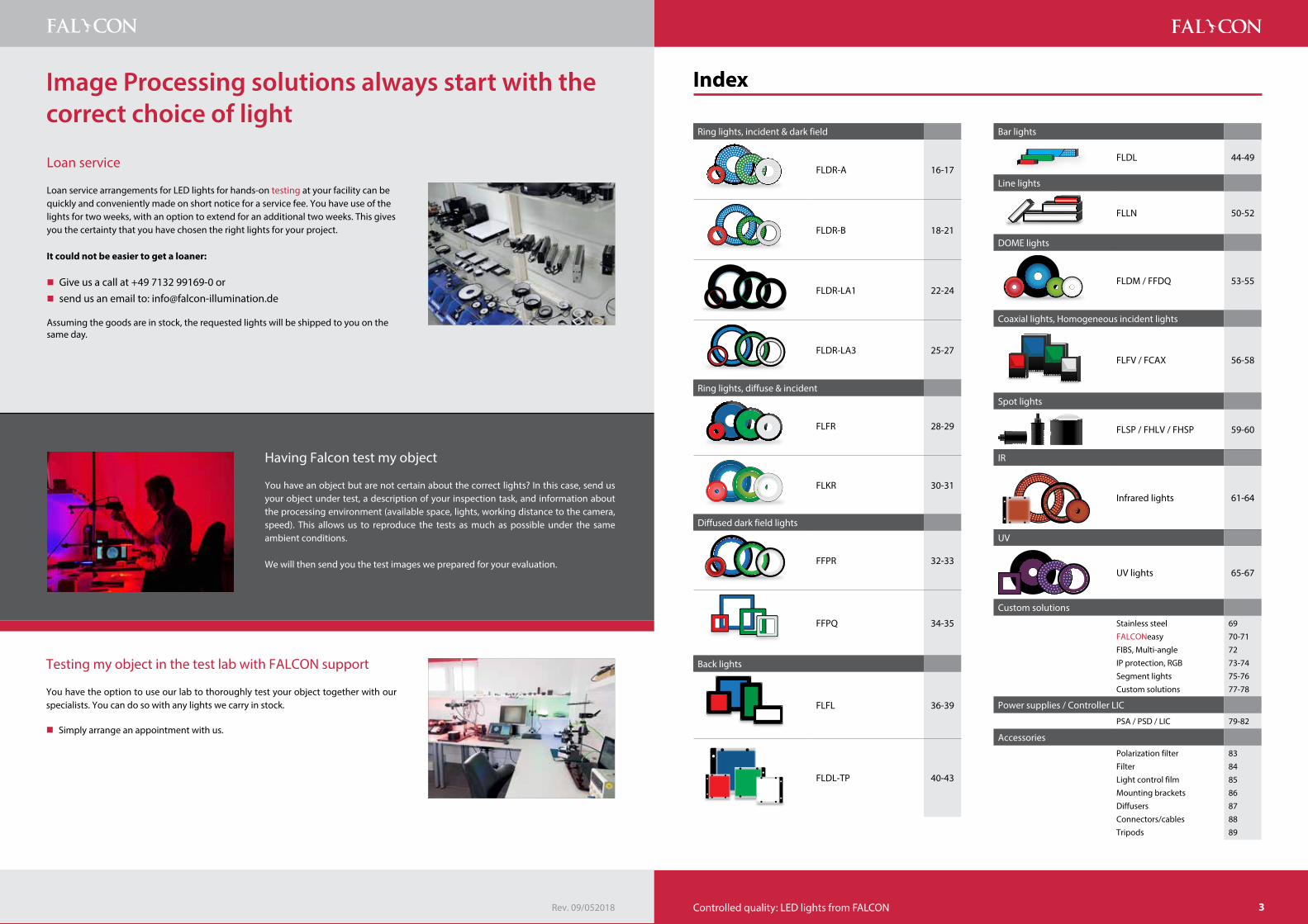
Ring lights, incident & dark field
FLDR-A 16-17
FLDR-B 18-21
FLDR-LA1 22-24
FLDR-LA3 25-27
Ring lights, diffuse & incident
FLFR 28-29
FLKR 30-31
Diffused dark field lights
FFPR 32-33
FFPQ 34-35
Back lights
FLFL 36-39
FLDL-TP 40-43
index
Bar lights
FLDL 44-49
Line lights
FLLN 50-52
DOME lights
FLDM / FFDQ 53-55
Coaxial lights, Homogeneous incident lights
FLFV / FCAX 56-58
Spot lights
FLSP / FHLV / FHSP 59-60
IR
Infrared lights 61-64
UV
UV lights 65-67
Custom solutions
Stainless steelFALCONeasy FIBS, Multi-angleIP protection, RGBSegment lightsCustom solutions
6970-7172 73-7475-7677-78
Power supplies / Controller LIC
PSA / PSD / LIC 79-82
Accessories
Polarization filterFilterLight control filmMounting bracketsDiffusersConnectors/cablesTripods
83848586 878889
Loan service
Loan service arrangements for LED lights for hands-on testing at your facility can be quickly and conveniently made on short notice for a service fee. You have use of the lights for two weeks, with an option to extend for an additional two weeks. This gives you the certainty that you have chosen the right lights for your project.
it could not be easier to get a loaner:
� Give us a call at +49 7132 99169-0 or � send us an email to: [email protected]
Assuming the goods are in stock, the requested lights will be shipped to you on the same day.
Having Falcon test my object
You have an object but are not certain about the correct lights? In this case, send us your object under test, a description of your inspection task, and information about the processing environment (available space, lights, working distance to the camera, speed). This allows us to reproduce the tests as much as possible under the same ambient conditions.
We will then send you the test images we prepared for your evaluation.
Testing my object in the test lab with FALCON support
You have the option to use our lab to thoroughly test your object together with our specialists. You can do so with any lights we carry in stock.
� Simply arrange an appointment with us.
Image Processing solutions always start with the correct choice of light
Rev. 09/052018 3

www.falcon-illumination.de | Fon +49 7132 99169-04 Controlled quality: LED lights from FALCON
hEAD OFFiCE
head Office
germany | Austria | Switzerland Falcon Illumination MV GmbH & Co. KGIn den Scheibigswiesen 874257 UntereisesheimGermany
Mail: [email protected]: falcon-illumination.dePhone: +49 7132 99169-0Fax: +49 7132 99169-10
head Office
Asia Falcon Illumination (M) Sdn. Bhd.No. 45, Lebuh Bukit Kecil 2Taman Sri Nibong11900 Bayan Lepas, PenangMalaysiaMail: [email protected]: falcon-illumination.comPhone: +604-646 8822Fax: +604-643 3388
head Office
Europe/internationalFalcon LED Europe Ltd.In den Scheibigswiesen 874257 UntereisesheimGermany
Mail: [email protected]: falcon.lightingPhone: +49 7132 99169-0Fax: +49 7132 99169-10
WORLDWiDE
Europe
NetherlandsIsotron Systems B.V.Afrikalaan 21-235232 BD ´s-HertogenboschThe NetherlandsMr. Ronald GoedhartMail: [email protected]: isotron.euPhone: +31 73 639 16-39Fax: +31 73 639 16-99
Belgium | LuxembourgIsotron Systems BVBAAntwerpse Steenweg 452830 Willebroek, BelgiumMr. Guido Creemers Mail: [email protected] Web: isotron.bePhone: +32 3 450 70 45Fax: +32 3 450 70 46
FranceFRAMOS France GmbH40, Rue des Vignobles 2A78400 Chatou, FranceMr. Marek TrejgisMail: [email protected]: framos.euPhone: +33 1395207-82
hungarySANXO-Systems Finnish-Hungrian Measurement and Automation Ltd.Arany J. út 87/B1221 Budapest, HungaryMr. Sándor TòthMail: [email protected]: sanxo.huPhone/Fax: +36 (06) 1 226 26 24
italyANTARES VISION SRLVia Roncadelle 70/A25030 Castel Mella (Brescia), ItalyMail: [email protected]: antaresvision.comPhone: +39 (0)30 2781058
italyFRAMOS Italia SrlCentro Colleoni, Pal.Taurus, Intr.2Viale Colleoni, 320864 Agrate Brianza (MB), ItalyMr. Sandro CeleriMail: [email protected]: framos.itPhone: +39 03968 99 635Fax: +39 03968 98 065
SpainVisionOnline S.L.Paseo de Ronda 508350 Arenys de Mar (Barcelona)SpainMr. Sr. Jaume FontanellaMail: [email protected]: visiononline.esPhone: +34 9379 23 455Skype: vision-online
SloveniaTipteh d.o.o.Ulica Ivana Roba 231000 Ljubljana, SlowenienMr. Marko DjukicMail: [email protected]: tipteh.siPhone: +38 612 00 51 59
United Kingdom | irelandFRAMOS Electronics Ltd.The Coliseum Business CentreRiverside Way, Camberley, Surrey GU15 3YLUnited KingdomMail: [email protected]: framos.comPhone: +44 (0)1276 404140
Overseas
Australia | New Zealand | OceaniaSensorplex Pty Ltd.Unit B3/2A Halmarc Business ParkCnr Westall & Centre RoadsClayton Vic 3168, AustraliaMail: [email protected]: sensorplex.comPhone: +611 3 9562-6699
CanadaFRAMOS Technologies Inc.57 Auriga Drive, Suite 203Ottawa, Ontario K2E 8B2Mr. Mohamed HaidaraMail: [email protected]: framos.comPhone: +1 613686 1152
ChinaFalcon China c/o CWCRoom 608, Bantian Business CenterShenzhen, ChinaMr. Yu, Ding Yan (Mr. Allen)Mail: [email protected]: falconillumination.comPhone: +86-0755-81470894
thailandFLUIDX ASIA CO., LTD.19/59 Moo 3, T. Klong NeungA. Klong LuangPathumthani 12120, ThailandPhone: +66 2902 0900Fax: +66 2902 0901Mail: [email protected]
SingaporeRisto Technology Pte. Ltd.Mail: [email protected]: ristotechnology.comPhone: +65 6570-0315Fax: +65 6570-0314
SingaporeVital Vision Technology Pte. Ltd.Mail: [email protected]: v2tech.com.sgPhone: +65 6509-3409Fax: +65 6509-3405
5
www.falcon-illumination.de | Fon +49 7132 99169-06 Controlled quality: LED lights from FALCON
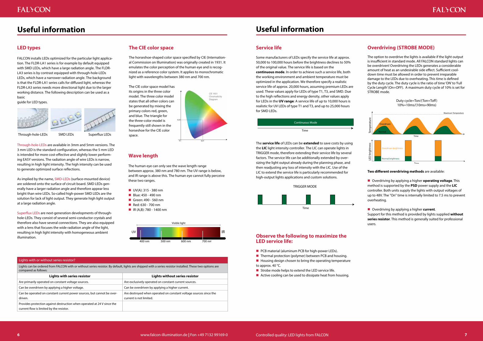
Wave length
The human eye can only see the wave length range between approx. 380 nm and 780 nm. The UV range is below, and IR range is above this. The human eye cannot fully perceive these two ranges.
� UV(A): 315 - 380 nm � Blue: 450 - 490 nm � Green: 490 - 560 nm � Red: 630 - 700 nm � IR (A,B): 780 - 1400 nm
Useful information
the CiE color space
The horseshoe-shaped color space specified by CIE (Internation-al Commission on Illumination) was originally created in 1931. It emulates the color perception of the human eye and is recog-nized as a reference color system. It applies to monochromatic light with wavelengths between 380 nm and 700 nm.
The CIE color space model has its origins in the three color model. The three color model states that all other colors can be generated by mixing the primary colors red, green, and blue. The triangle for the three-color model is frequently still shown in the horseshoe for the CIE color space.
Useful information
CIE 1931ChromaticityDiagram
0,31
0,32
0
Service life
Some manufacturers of LEDs specify the service life at approx. 50,000 to 100,000 hours before the brightness declines to 50% of the original value. The service life is based on the continuous mode. In order to achieve such a service life, both the working environment and ambient temperature must be optimized in the application. We therefore specify a realistic service life of approx. 20,000 hours, assuming premium LEDs are used. These values apply for LEDs of type T1, T3, and SMD. Due to the high reflections and energy density, other values apply for LEDs in the UV range: A service life of up to 10,000 hours is realistic for UV LEDs of type T1 and T3, and up to 25,000 hours for SMD LEDs.
Continuous Mode
Time
The service life of LEDs can be extended to save costs by using the LiC light intensity controller. The LIC can operate lights in TRIGGER mode, therefore extending their service life by several factors. The service life can be additionally extended by over-sizing the light output already during the planning phase, and then readjusting any loss of intensity with the LIC. Use of the LIC to extend the service life is particularly recommended for high-output lights applications and custom solutions.
TRIGGER MODE
Time
Observe the following to maximize the LED service life:
� PCB material (aluminum PCB for high-power LEDs). � Thermal protection (polymer) between PCB and housing. � Housing design chosen to bring the operating temperature
to approx. 40 °C. � Strobe mode helps to extend the LED service life. � Active cooling can be used to dissipate heat from housing.
Overdriving (StROBE MODE)
The option to overdrive the lights is available if the light output is insufficient in standard mode. All FALCON standard lights can be overdriven! Overdriving the LEDs generates a considerable amount of heat as an undesirable side effect. Sufficient cool-down time must be allowed in order to prevent irreparable damage to the LEDs due to overheating. This time is defined by the duty cycle. The duty cycle is the ratio of time ‘ON’ to ‘Full Cycle Length’ (On+OFF). A maximum duty cycle of 10% is set for STROBE mode.
Duty cycle=Ton/(Ton+Toff)10%=10ms/(10ms+90ms)
Maximum Temperature
Normal
Overdriven
Tem
pera
ture
Time
Normal brightness
Overdriven brightness
Time
LED
brig
htne
ss
two different overdriving methods are available:
� Overdriving by applying a higher operating voltage. This method is supported by the PSD power supply and the LiC controller. Both units supply the lights with output voltages of up to 48V. The "On" time is internally limited to 7.5 ms to prevent overheating.
� Overdriving by applying a higher current. Support for this method is provided by lights supplied without series resistor. This method is generally suited for professional users.
Lights with or without series resistor?
Lights can be ordered from FALCON with or without series resistor. By default, lights are shipped with a series resistor installed. These two options are compared as follows:
Lights with series resistor Lights without series resistor
Are primarily operated on constant voltage sources. Are exclusively operated on constant current sources.
Can be overdriven by applying a higher voltage. Can be overdriven by applying a higher current.
Can be operated on constant current power sources, but cannot be over-driven.
Are destroyed when operated on constant voltage sources since the current is not limited.
Provides protection against destruction when operated at 24 V since the current flow is limited by the resistor.
LED types
FALCON installs LEDs optimized for the particular light applica-tion. The FLDR-LA1 series is for example by default equipped with SMD LEDs, which have a large radiation angle. The FLDR-LA3 series is by contrast equipped with through-hole-LEDs LEDs, which have a narrower radiation angle. The background is that the FLDR-LA1 series calls for diffused light, whereas the FLDR-LA3 series needs more directional light due to the larger working distance. The following description can be used as a basic guide for LED types.
Through-hole-LEDs SMD LEDs Superflux LEDs
Through-hole-LEDs are available in 3mm and 5mm versions. The 3 mm LED is the standard configuration, whereas the 5 mm LED is intended for more cost-effective and slightly lower perform-ing EASY versions. The radiation angle of wire LEDs is narrow, resulting in high light intensity. The high intensity can be used to generate optimized surface reflections.
As implied by the name, SMD-LEDs (surface-mounted device) are soldered onto the surface of circuit board. SMD LEDs gen-erally have a larger radiation angle and therefore appear less bright than wire LEDs. So-called high-power SMD LEDs are the solution for lack of light output. They generate high light output at a large radiation angle.
Superflux LEDs are next-generation developments of through-hole-LEDs. They consist of several semi-conductor crystals and therefore also have several connections. They are also equipped with a lens that focuses the wide radiation angle of the light, resulting in high light intensity with homogeneous ambient illumination.
7

8 9
For questions:
PHONE +49 7132 99169-0FAX +49 7132 99169-10
illumination angle
Object levelObject level
Dark�eld
Bright�eld
Dark�el
d
Dark
�eld
Bright�eld
Dark�eld
Back Light
Front Light
OBJECT
FLDR-LA
3
FLFLFLDL-TP
FLDM
FLDR-AFLDR-B
Coax FLFV
FLLNFLDL
FHSP FFPR/FFPQ FLLN FLDL FLD
R-LA3 FLDR-LA
1Original DSUB connector
The primary function of lights is to maximize the contrast differentiation between the defect attribute and component. The illumination angle and light form have a significant influence on how inspection and defect attributes are rendered visible in the image.
The light can be arranged to illuminate from above, at an angle from the side, from both sides, horizontally, or from below onto the inspected object. Depending on the surface texture, material properties and form, the inspected object and its defect attributes reflect, diffuse, absorb, or transmit the light, or throw a shadow. Other than the illumination angle, it is also important whether the light shines directly onto the inspected object or is diffused.
Depending on how the light is positioned, the same object will generate completely different results in the camera image.The following graphic shows images of an objects using various illumination angles.
FLDR-A FLDR-i50A FLDR-i70A FLDR-i90A
FLDR-i70A FLFR-Si100 FLFR-Si100 FLFR-Si200
illumination angle
Incident light, direct
Direct incident light can be used when highly-reflective surfaces are inspected on embossing or engraving, or when less reflective colors are inspected.
FLKR-Si100 FLDR-i90B FLDR-i70B FLDR-i90B
FLKR-Si100 FLKR-Si100
Incident light, angled
Similar to direct incident light, angled incident light is highly suited for inspecting surface textures. The slight tilt of the LEDs highlights edges better and shadows are created in depressions.
Incident Ray Re�ected Ray
the law of reflection is the fundamental rule for arranging lights:
Angle of incidence = Angle of reflection

10 11
For questions:
PHONE +49 7132 99169-0FAX +49 7132 99169-10
illumination angle
FFPR-Si100 FLDR-i100-LA3 FLDR-i100-LA3 FLDR-i100-LA3
FLDR-i100-LA3 FLDR-i100-LA3 FLDR-i100-LA3
Dark field, tilted
Dark field lights accentuate beveled edges and scratches while at the same time giving the flat surface within a depression a dark appear-ance.
FLDR-Si130-LA1 FLDR-Si130-LA1 FLDR-i220-LA1 FLDR-Si100-LA1
FLDR-Si100-LA1 FLDR-Si100-LA1 FLDR-Si100-LA1 FLDR-Si100-LA1
FLDR-Si100-LA1 FLDR-Si120-LA1 FLDR-Si130-LA1 FLDR-Si220-LA1
Dark field, horizontal
Horizontal dark field lights are frequently used for position control. They create enormous contrast between brightly lit edges and surfaces rendered in black.
FLDL FLDL-TP FLDL-TP FLDL-TP-Si100
FLDL-TP-Si100 FLDL-TP-Si200x100 FLDL-TP FLFL
FLDL-TP FLDL-TP
Back light
Back light is used to shine through thin materials in order to detect inclusions. Position controls for opaque parts are also easily imple-mented.
illumination angle

12 13
For questions:
PHONE +49 7132 99169-0FAX +49 7132 99169-10
FLFV-Si100 FLFV-Si100 FLFV FLFV-Si25N
FLFV-Si70N FLFV-Si70N FLFV-Si70N
Coaxial
Coaxial lights create a homogeneous illumination of highly-reflective surfaces, while the internally installed one-way mirror permits illumi-nation without a camera aperture.
illumination angle
FLDM-i250 FLDM-i100 FLDM-i200 FLDM-i100
FLDM-i100 FLDM-i100 FLDM-i250 FLDM-i100
Dome
Dome lights allow uneven textures to be fully illuminated, thus eliminating height differences. The indirect and extremely diffused light also gives shiny surfaces a more matte appearance than with direct light.
illumination color
The use of colored lights is of elementary importance in industrial image processing applications. Different light colors have various effects on colored objects.
When the wave length of the object approximately matches the light color (e.g. red light color and red object), the two cancel each other, rendering the objects or print very bright to white. Conversely, a complementary color (opposing color) can be used to render the object very dark to black (e.g. blue light color and red object).A skilled match of colored light with the color of the inspected object can then be used to achieve an increase or decrease of contrast.
White Blue Green Red
re�ected ray
absorbed ray
Original object, red
Result for red light Result for blue light
Example based on red light; the illuminated object is red
Colored pensThe image on the left shows colored pens illuminated with white light. This creates reflections on colored pens with large white content, such as yellow. The reflection then results in bright image sections. By contrast, the color black has a small content of white light. The white light is therefore absorbed and no reflection is generated and a dark image section is captured. Complementary colors act in the same manner as black and white, Complementary colors are located opposite to each other in the color wheel; for instance red and green. The reflection and absorption properties as it relates to light colors can be exploited for inspection tasks.
The light colors ultraviolet (UV) and infrared (IR) must be treated separately. They are in the not visible spectrum and are therefore also not shown in the color wheel. There is nevertheless a guideline for using UV and IR light. UV light is generally used to illuminate fluorescent substances. Due to its short wave radiation, UV light also generates enormous reflections on metal surfaces. By contrast, IR light generates less reflection due to its long wave radiation. It penetrates materials or can even shine through these. Colors are then blended out and textures are rendered visible.
Chocolate barsThe effects of complementary colors are first shown using chocolate bars as an example. When illuminated with red light, the red packag-ing appears white. When it is illuminated with the complementary color blue, the same image section appears dark. The rule of thumb is: Equivalency is reflected/returned, opposites are absorbed.

14 15
For questions:
PHONE +49 7132 99169-0FAX +49 7132 99169-10
Original Blue Green Red
White IR
The following illustration shows a yogurt lid illuminated with various colors. Depending on the light color, the contrast for certain colors is increased or decreased.
illumination color
Original blood filter UV Blue Red
White
This task involved inspecting the tubes of the blood filter for blockages. This calls for creating a strong contrast differential between the tubes and the remaining surface. The greatest possible contrast differential is achieved with UV light. Due to the short wavelength, the material is reflected or absorbed even for minimal penetration depths. The deeper levels of the material are then filtered out, whereas the surface is highlighted. Higher wave lengths such as red or infrared are suited for penetrating deeper into the material to highlight foreign objects within the material.
Original White Blue Red
IR
illumination color
Original White Blue Red
IR
Original White UV Blue
Green Red IR

www.falcon-illumination.de | Fon +49 7132 99169-016 Red Green Blue WhiteSR SuperRed UV IR
Kamera
LED
Objekt
FLDR-A
FLDR-i56A FLDR-i70A FLDR-i90A
FLDR-A
Model Color Volt Wattage LED typeDimensions in mm
Outsidedimensions
illuminatedarea
innerdiameter
FLDR-Si32A 241,92
SMD Ø 37 Ø 32 Ø 18iR 0,60 1,44
FLDR-i50ASR
242,88
T1 3mm Ø 49 Ø 43 Ø 21iR 1,80 2,88
FLDR-i56ASR
245,04
T1 3mm Ø 56 Ø 52 Ø 23,5iR 3,00 5,76
FLDR-i70A
SR
24
7,20
T1 5mm Ø 70 Ø 65 Ø 30iR 3,60 7,68UV 3,84
FLDR-i90A 2410,08
T1 3mmØ 102 Ø 90 Ø 40iR 6,00
11,52 T1 5mmFLDR-i120A SR 24 - - Ø 120 Ø 108 Ø 48FLDR-i192A 24 33,60 P4 Ø 192 Ø 180 -
FhDR-A High-Power
FHDR-Si90A UV 24 24 SMD Ø 100 Ø 84 Ø 50
FHDR-i120A-IP65
2425,20 T1 3mm
Ø 100 Ø 84 Ø 50UV 24 SMD
FHDR-Si426A 24 57,60 SMD Ø 426 Ø 410 Ø 330
FLDR-A Half models
FLDR-i90A-HC180 24 - T1 3mm - - -
Other sizes available on request.
FLDR-Si32A FLDR-i50A
d Original d FLDR-A
d Original d FLDR-A
FLDR-A
PropertiesThe FLDR-A series is classified as incident light. The vertical alignment of the LEDs allows the FLDR-A series to be used with highly variable working distances. It is ideally suited for illuminating round and matte inspection objects, but at the same time frequently also gives outstanding results on other surfaces and shapes. Attributes can then also be detected on reflective materials by using the optionally available diffuser or polarization filter. High-power versions are available for applications with high light requirements.
Application examplesDistinguish matte and reflective partial areas, for instance on embossed stamps, metal contacts, solder joints, circuit board inspections.Distinguish printing with different reflection strengths, for instance for barcodes.
Options � Colors: R, G, B, SR, IR 850, W, UV375, UV400, � Protection class: IP 30 as standard, available up to IP 67 � Material: Aluminum (standard), stainless steel (on request) � Without series resistor or with series resistor (page 7)
Accessories, from page 83 � Industrial-strength M8 & M12 connectors � Diffusers � Polarization filter � Mounting brackets
Direct incident light illumination, ring light
5-250 mm working distance
Continuous and flash mode
Connector: JST (optional M8, M12)
without diffuser (optional)
Al Housing: Al (optional stainless steel)
LED angle: 0°
17

www.falcon-illumination.de | Fon +49 7132 99169-018 Red Green Blue WhiteSR SuperRed UV IR
Kamera
LED
Objekt
d Original d FLDR-B
d Original d FLDR-B
d Original d FLDR-B
FLDR-B
FLDR-B
Model Color Volt Wattage LED typeDimensions in mm
Outsidedimensions
illuminatedarea
innerdiameter
FLDR-Si20B 240,96
SMD Ø 20 Ø 17 Ø 6 0,96
FLDR-Si32B24
1,92
SMD Ø 32 Ø 28 Ø 10iR 0,60 1,44UV 12 1,44
FLDR-i38B
SR
24
1,44T1 3 mm
Ø 38 Ø 32 Ø 15iR 1,20 2,40UV 0,96 T1 5 mm
FLDR-i50B
SR
24
3,60T1 3 mm
Ø 49 Ø 47 Ø 25iR 2,40 3,84UV 1,44 T1 5 mm
FLDR-Si50B 243,84
SMD Ø 49 Ø 47 Ø 25 2,88
FLDR-i70BSR
246,48
T1 3 mm Ø 70 Ø 65 Ø 30iR 3,60 7,20
FLDR-Si70B RgB 24R:2,40 B:3,30 G:3,36
RGB-LED Ø 70 Ø 65 Ø 30
FLDR-i75B UV 24 1,92 T1 5 mm Ø 75 Ø 69 Ø 45
FLDR-i90B
SR 12 12,24T1 3 mm Ø 93,5 Ø 87 Ø 5024 9,60
iR 24 7,20 13,44
Ø 90 Ø 86 Ø 54UV 12 5,76 T1 5 mm24FLDR-Si90B-RGB RgB 24 10,32 RGB-LED Ø 93,5 Ø 87 Ø 50
FLDR-Si90B-AOI 24 6,24 SMD Ø 90 Ø 82 Ø 50
FLDR-i100B-UV UV12 3,12
T1 5 mm Ø 103 Ø 99 Ø 6524 6,24
FLDR-i100B-UV-W5 UV/W 24 W= 3,36 UV= 2,88 T1 5 mm Ø 103 Ø 98 Ø 65
FLDR-i120BSR
2428,80
T1 3 mm Ø 128 Ø 112 Ø 63,5iR 20,40 32,64
FLDR-Si120B-RGB RgB 24 R:9,60 B:6,72 G:6,72 Ø 122 Ø 112 Ø 63,5
d Original d FLDR-B-W
FLDR-B
PropertiesThe FLDR-B series represents angled incident lights. The LED tilt depends on the illumination size and ranges between 19° and 45° to the horizontal. The FLDR-B series is ideally suited for illuminating round and matte inspection objects, but at the same time frequently also gives outstanding results on other surfaces and shapes. Reflective inspected objects can also be detected by using the optionally available diffuser. High-power versions are also available for applications with particularly high light requirements.
Application examplesHighlighting slightly beveled edges or round depressions, such as engraving.Print inspections, orientation detection
Options � Colors: UV365, UV 375,UV 400, B, G, R, SR, IR 875, W, RGB � Protection class: IP 30 as standard, IP 67 available � Material: Aluminum (standard), stainless steel (on request) � Without series resistor or with series resistor � Custom solutions: Segment lights � Falcon Easy
Accessories, from page 83 � Industrial-strength M8 & M12 connectors � Diffusers � Polarization filter � Mounting brackets
Working distance: approx. 1-100 mm
Continuous and flash mode
Connector: JST (optional M8, M12)
without diffuser (optional)
Al Housing: Al (optional stainless steel)
LED angle: 19°-45°
Direct incident light with angle
19

www.falcon-illumination.de | Fon +49 7132 99169-020 Red Green Blue WhiteSR SuperRed UV IR
FLDR-B
FLDR-B
Model Color Volt Wattage LED typeDimensions in mm
Outsidedimensions
illuminatedarea
innerdiameter
FLDR-i230B 24
36,00 P4
Ø 235 Ø 220 Ø 145iR 31,20 T1 5 mm 48,00
P4UV -
FLDR-i230B-4 24 28,80 P4 Ø 235 Ø 220 Ø 145
FLDR-i230B-8 2428,80
P4 Ø 235 Ø 220 Ø 145 48,00
FLDR-i300B 24 - P4 Ø 305 Ø 286 Ø 200
FLDR-i300B-4 24 33,60 P4 Ø 305 Ø 286 Ø 200
FLDR-i300B-8 24 48,00 P4 Ø 305 Ø 286 Ø 200
FLDR-i420B 24 76,80 P4 Ø 430 Ø 408 Ø 325
FLDR-i420B-8 24 76,80 P4 Ø 430 Ø 408 Ø 325
FhDR-B High Power
FHDR-Si75B UV 24 25,20 SMD Ø 75 Ø 69 Ø 45
FHDR-Si90B iR 24 50,40 SMD Ø 93,5 Ø 87 –
FLDR-B Half modelsFLDR-i38NB-HC180 24 0,96 T1 3mm Ø 38x18 Ø 35 Ø 13FLDR-i45NB-HC180 24 1,44 T1 3mm Ø 45x18 Ø 42 Ø 20FLDR-i50NB-HC180 24 1,44 T1 3mm Ø 50x18 Ø 47 Ø 25
FLDR-i55NB-HC180SR
24 1,44 T1 3mm Ø 55x18 Ø 52 Ø 30
Other sizes available on request.
FLDR-Si20B FLDR-i32B FLDR-i38B
2 X M3 4, PCD 14Equal Spacing
17( I
llum
inat
ion
Are
a )
12
19°
6( F
OV
)
20
45°
4 X M3 4, PCD 20Equal Spacing
10 (
FOV
)
32
16
( Illu
min
atio
n ar
ea )
28
19°
300
45°
4 X M3 4, PCD 28Equal Spacing
38 15( F
OV
)
16.6
15°
300
FLDR-i50B FLDR-i70B FLDR-i90B
45°
4 X M3 4, PCD 40Equal Spacing
300
25( F
OV
)
49
( Illu
min
atio
n ar
ea )
47
17.2
20°
45°
4 X M3 4, PCD 50Equal Spacing
30( F
OV
)
70
20°
( Illu
min
atio
n ar
ea )
65
22.5
300
45°
4 X M3 4, PCD 70Equal Spacing
50( F
OV
)
20°
( Illu
min
atio
n ar
ea )
8793.5
24.6
300
FLDR-Si90B-RGB FLDR-i100B FLDR-i120B
45°
4 X M3 4, PCD 70Equal Spacing
24.6
20°
( Illu
min
atio
n ar
ea )
8750( F
OV
)
93.5
300
150
45°
4 X M3 4, PCD 70Equal Spacing
4 X M3 4, PCD 80Equal Spacing
( Illu
min
atio
n ar
ea )
9865( F
OV
)
2019°
103
300
FLDR-i230B FLDR-i300B-8 FLDR-i420B-8
45°
4 X M4 6, PCD 186Equal Spacing
235
220
(Illu
min
atio
n A
rea)
145
(FO
V)
40 45°
600
135
70
270
45°
4 X M5 8, PCD 280Equal Spacing8 X M5 8
200
( FO
V )
286
( Illu
min
atio
n ar
ea )
40
305
18.5°
800
70
190
380
45°
8 X M4 44 X M4 4, PCD 380Equal Spacing
39
408
( Illu
min
atio
n ar
ea )
325
( FO
V )
430
20°
500
FLDR-B
21

www.falcon-illumination.de | Fon +49 7132 99169-022 Red Green Blue WhiteSR SuperRed UV IR
LEDObjekt
Kamera
d Original d FLDR-LA1
d Original d FLDR-LA1
d Original d FLDR-LA1
FLDR-LA1
Model Color Volt Wattage LED typeDimensions in mm
Outsidedimensions
illuminatedarea
innerdiameter
FLDR-Si31-LA1 240,96
SMD Ø 31 Ø 20 Ø 20 0,96
FLDR-Si35-LA1 241,92
SMD Ø 35 Ø 17 Ø 17 0,96
FLDR-Si49-LA1 242,88
SMD Ø 49 Ø 26 Ø 26iR 1,20 1,92
FLDR-Si75-LA1 243,60
SMD Ø 75 Ø 50 Ø 50iR 2,40 3,36
FLDR-Si100-LA1
SR24
3,60
SMD Ø 102
Ø 65 Ø 656,72
Ø 65 Ø 65iR 12 3,00
244,80
UV 4,80FLDR-i100-LA1-UV UV 400 24 2,88 T1 5mm Ø 105 Ø 65 Ø 65
FLDR-i120-LA1 UV 400 24 4,32 T1 5mm Ø 105 Ø 65 Ø 65
FLDR-Si130-LA1 249,60
SMD Ø 130 Ø 94 Ø 94iR 4,20 6,72
FLDR-Si150-LA1 249,60
SMD Ø 150 Ø 110 Ø 110 6,72
FLDR-Si180-LA1 2411,52
SMD Ø 180 Ø 150 Ø 150iR 5,40 9,12
FLDR-Si220-LA124 15,36
SMD Ø 220 Ø 185 Ø 185iR 12 7,20 24 11,52
FLDR-Si255-LA1 24 13,44 SMD Ø 255 Ø 220 Ø 220
FLDR-i350-LA1 24 16,80 P4 Ø 346 Ø 286 Ø 286
FLDR-LA1 Half models 150-240 degreesFLDR-Si70-LA1-HC150 24 - SMD - - -
FLDR-Si70-LA1-HC220 24 1,92 SMD Ø 70 Ø 34 -
FLDR-Si75-LA1-HC120 24 16,80 SMD Ø 75 Ø 50 -
FHDR-Si75-LA1-HC120 24 16,80 SMD Ø 75 Ø 50 -
FLDR-Si75-LA1-HC180 24 1,92 SMD Ø 75 Ø 50 -
FLDR-Si130-LA1-HC18024 5,76
SMD Ø 130 Ø 94 - 24 3,84
Other sizes available on request.
FLDR-LA1
0-20 mm working distance
x˚ LED angle: 90°
Continuous and flash mode
Connector: JST (optional M8, M12)
Diffuser
Al Housing: Al (optional stainless steel)
PropertiesFLDR-LA1 series strictly represents dark field lights. LEDs are tilted 90° to the horizon-tal. The light emission is correspondingly oriented parallel to the illumination cen-terpoint. The ring shape of the light and the high homogeneity specifically highlight the edges of round inspection objects, whereas level surfaces below the edge are rendered completely dark. The FLDR-LA1 series is by default equipped with diffuser (excluding UV). High-power versions are also available for applications with particu-larly high light requirements.
Application examplesIdeal for edge inspections and for inspecting embossing Inspecting surface for scratches or nonconformancesUV suited for microscopy applications
Options � Colors: UV375, UV 400, B, G, R, SR, IR 850, W � Protection class: IP 30 as standard, available up to IP 55 � Material: Aluminum (standard), stainless steel (on request) � Without series resistor or with series resistor
Accessories, from page 83 � Industrial-strength M8 & M12 connectors � Mounting brackets
Horizontal dark field lights
23

www.falcon-illumination.de | Fon +49 7132 99169-024 Red Green Blue WhiteSR SuperRed UV IR
FLDR-LA1
FLDR-Si31-LA1 FLDR-Si49-LA1 FLDR-Si75-LA1
45°
4 X M3 4, PCD 24.5Equal Spacing
13 02
)V
OF(
10
02)aer
A noitanimullI(
300
45°
10°
4 X M3 Tap Through Hole, PCD 43, Equal Spacing 300
26( I
llum
inat
ion
area
)
26( F
OV
)
7
49
45°
4 X M3 4, PCD 56Equal Spacing
75 50( F
OV
)
50( I
llum
inat
ion
area
)
300
FLDR-Si100-LA1 FLDR-i120-LA1-UV FLDR-Si130-LA1
45°
4 X M3 4, PCD 80Equal Spacing
65( I
llum
inat
ion
area
)
12
65( F
OV
)
102
300
45°
4 X M3 4, PCD 104Equal Spacing
021
57)
VOF(
57) aer
A noi t animullI (
12
400
40 100
14
Note: External Resistor will be use if noInternal Resistor
FLDR-Si150-LA1 FLDR-Si180-LA1 FLDR-Si220-LA1
45°
4 X M3 4, PCD 130Equal Spacing
12
110
( Illu
min
atio
n ar
ea )
150
110
( FO
V )
300
45°
4 X M3 4, PCD 173Equal Spacing
150
( Illu
min
atio
n ar
ea )
180
150
( FO
V )
300
45°
4 X M3 4, PCD 190Equal Spacing
220
185
( FO
V )
185
( Illu
min
atio
n ar
ea )
300
FLDR-Si255-LA14 X M3 7, PCD 248Equal Spacing
45°
600
220
(Illu
min
atio
n A
rea
)
220
(FO
V)
255
12
FLDR-Si75-LA1-HC180 FLDR-Si130-LA1-HC180
39.6
39.5
45°90
°
2 X M3 4, PCD 5690 Equal Spacing
75
10
50( I
llum
inat
ion
area
)
300
81.3
67
45°90
°
2 X M3 4, PCD 11590 Equal Spacing
300 130
94( I
llum
inat
ion
area
)
12
Red Green Blue WhiteSR SuperRed UV iR
Kamera
LED
Objekt
d Original d FLDR-LA3
d Original d FLDR-i100-LA3-W
FLDR-LA3
0-100 mm working distance
x˚ LED angle: 60° - 75°
Continuous and flash mode
Connector: JST (optional M8, M12)
without diffuser (optional)
Al Housing: Al (optional stainless steel)
PropertiesThe FLDR-LA3 series represents dark field lights. Depending on lights size, its LEDs are arranged at angles between 60° and 75° to the horizontal. The flat irradiation angle allows objects to be illuminated without a total reflection in the direction of the camera. However, on scratches or engraving, the light is projected directly to the camera sensor. The FLDR-LA3 series supports a wide range of uses due to its enormous light intensity in combination with the flatly radiated and widely scattered light.
Application examplesThe LA3 series is predominantly used for surface inspections. The flat intromission angle of the light highlights scratches, engraving, or edges of and on objects.The enormous light output and the flat radiation angle allow relatively large surfaces to be illuminated in the UV spectrum. Invisible barcodes, type identifiers, or safety attributes are then preferably inspected with this type of light.
Options � Colors: UV 375, UV 400, B, G, R, SR, IR 875 , W � Protection class: IP 30 as standard, available up to IP 55 � Material: Aluminum (standard), stainless steel (on request) � Without series resistor or with series resistor � Custom solutions: Segment lights
Accessories, from page 83 � Industrial-strength M8 & M12 connectors � Mounting brackets � Diffuser � Polarization filter
Flat angle dark field lights
25
www.falcon-illumination.de | Fon +49 7132 99169-026 Red Green Blue WhiteSR SuperRed UV IR
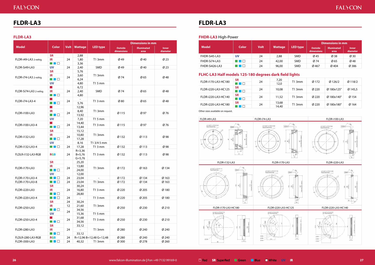
FLDR-LA3
FLDR-LA3
Model Color Volt Wattage LED typeDimensions in mm
Outsidedimensions
illuminatedarea
innerdiameter
FLDR-i49-LA3 2-reihig
SR24
2,88T1 3mm Ø 49 Ø 40 Ø 23iR 1,80
3,36FLDR-Si49-LA3 UV 24 2,40 SMD Ø 49 Ø 40 Ø 23
FLDR-i74-LA3 2-reihig
SR
24
5,76T1 3mm
Ø 74 Ø 65 Ø 48iR 3,60 6,24UV 4,80 T1 5 mm
FLDR-Si74-LA3 2-reihig 246,72
SMD Ø 74 Ø 65 Ø 48iR 2,40 4,80
FLDR-i74-LA3-4 24-
T1 3 mm Ø 80 Ø 65 Ø 48 5,76
FLDR-i100-LA3 24
12,96T1 3mm
Ø 115 Ø 97 Ø 76iR 8,40 13,92UV 7,20 T1 5 mm
FLDR-i100-LA3-4
2414,40
T1 3 mm Ø 115 Ø 97 Ø 76 13,44
FLDR-i132-LA3
SR
24
15,12T1 3mm
Ø 132 Ø 113 Ø 98iR 10,80 17,28UV 8,16 T1 3/4 5 mm
FLDR-i132-LA3-4 24 17,28 T1 3 mm Ø 132 Ø 113 Ø 98
FLDLR-i132-LA3-RGB RgB 24R=3,36 B=5,76 G=5,76
T1 3 mm Ø 132 Ø 113 Ø 98
FLDR-i170-LA3
SR
24
25,20
T1 3mm Ø 172 Ø 163 Ø 134iR 13,80 24,00UV 12,00
FLDR-i170-LA3-4 24 23,04 - Ø 172 Ø 134 Ø 163FLDR-i170-LA3-8 24 23,04 T1 3mm Ø 172 Ø 134 Ø 163
FLDR-i220-LA3SR
2430,24
T1 3 mm Ø 220 Ø 205 Ø 180iR 16,80 28,80
FLDR-i220-LA3-4 24 - T1 3 mm Ø 220 Ø 205 Ø 180
FLDR-i250-LA3
SR 24 30,24T1 3mm
Ø 250 Ø 230 Ø 210iR 12 21,60
2434,56
UV 15,36 T1 5 mm
FLDR-i250-LA3-4
2431,68
T1 3 mm Ø 250 Ø 230 Ø 210 34,56
FLDR-i280-LA3SR
2433,12
T1 3mm Ø 280 Ø 240 Ø 240iR - 33,12
FLDLR-i280-LA3-RGB RgB 24 R=12,96 B=12,48 G=12,48 Ø 280 Ø 240 Ø 240FLDR-i300-LA3 24 40,32 T1 3mm Ø 300 Ø 278 Ø 260
FLDR-LA3
FhDR-LA3 High-Power
Model Color Volt Wattage LED typeDimensions in mm
Outsidedimensions
illuminatedarea
innerdiameter
FHDR-Si45-LA3 UV 24 2,88 SMD Ø 45 Ø 38 Ø 30
FHDR-Si74-LA3 24 42,00 SMD Ø 74 Ø 65 Ø 48
FHDR-Si426-LA3 24 96,00 SMD Ø 467 Ø 404 Ø 386
FLhC-LA3 half models 125-180 degrees dark field lights
FLDR-i170-LA3-HC180SR
247,20
T1 3mm Ø 172 Ø 126/2 Ø 118/2 12,0
FLDR-i220-LA3-HC125SR
24 10,08 T1 3mm Ø 220 Ø 180x125° Ø 145,5
FLDR-i220-LA3-HC140SR
24 11,52 T1 3mm Ø 220 Ø 180x140° Ø 154
FLDR-i220-LA3-HC180SR
2413,68
T1 3mm Ø 220 Ø 180x180° Ø 164 14,40Other sizes available on request.
Red Green Blue WhiteSR SuperRed UV iR
FLDR-i49-LA3 FLDR-i74-LA3 FLDR-i100-LA3
45°
4 X M3 4, PCD 40Equal Spacing
300
49 23
(FO
V)
40(Il
lum
inat
ion
area
)
60°
19
45°
4 X M3 4, PCD 60Equal Spacing
300
48( F
OV
)
74 65( I
llum
inat
ion
area
)
19
60°
45°
4 X M3 4, PCD 84Equal Spacing
22
115
76( F
OV
)
97( I
llum
inat
ion
area
)
75°
300
FLDR-i132-LA3 FLDR-i170-LA3 FLDR-i220-LA3 300
45°
4 X M3 4, PCD 116Equal Spacing
22
75°
311) aer
A noitanimullI (
89)
VOF (
231
45°
4 X M3 4, PCD 154Equal Spacing
163
( Illu
min
atio
n ar
ea )
23
134
( FO
V )
172
75°
300
45°
4 X M3 4, PCD 200Equal Spacing
180
( FO
V )
75°
220
23
205
( Illu
min
atio
n ar
ea )
300
FLDR-i170-LA3-HC180 FLDR-i220-LA3-HC125 FLDR-i220-LA3-HC140
108.
9 45°90
°
88
2 X M3 4, PCD 15490 Equal Spacing
13411
8
172
126
( Illu
min
atio
n ar
ea )
23
300 141.
4 125° 19
790°
45°
73.9
2 X M3 4, PCD 20090 Equal Spacing
220
180
16423
145.
5
( 18
0 Illu
min
atio
n - 1
25 )
300
141.
4 140° 20
8
45°90
°
2 X M3 4, PCD 20090 Equal Spacing
220
180
164
154
( 18
0 Illu
min
atio
n - 1
40 )
23
300
27

www.falcon-illumination.de | Fon +49 7132 99169-028 Red Green Blue WhiteSR SuperRed UV IR
Kamera
LED
Objekt
d Original d FLFR-Si100-R24
FLFR, FLFQ
FLFR-Si70 FLFR-Si100 FLFR-Si200
45°
4 X M3 4, PCD 50Equal Spacing
60( I
llum
inat
ion
area
)
16
20( F
OV
)
80
300
45°
4 X M3 4, PCD 70Equal Spacing
90( I
llum
inat
ion
area
)
33( F
OV
)
110
16
300
45°
4 X M3 4, PCD 100Equal Spacing
195
( Illu
min
atio
n ar
ea )
70( F
OV
)
220
16
300
FLFR-Si250 FLFR-Si350 FLFQ-Si245x200
45°
4 X M3 4, PCD 150Equal Spacing
16
90( F
OV
)
270
246
( Illu
min
atio
n ar
ea )
300
45°
4 X M3 4, PCD 150Equal Spacing
4 X M5 4, PCD 180Equal Spacing
300
115
( FO
V )
16
350
322
( Illu
min
atio
n ar
ea )
270
225
( Illu
min
atio
n ar
ea )
245( Illumination area )
90( FOV )
164 X M3 4, PCD 150Equal Spacing
300
FLFR Round version
Model Color Volt Wattage LED typeDimensions in mm
Outsidedimensions
illuminatedarea
innerdiameter
FLFR-Si70 244,80
SMD Ø 80 Ø 60 Ø 20iR 2,40 3,84
FLFR-Si100 247,68
SMD Ø 110 Ø 90 Ø 33iR 3,00 5,28
FLFR-Si200 2415,36
SMD Ø 220 Ø 195 Ø 70iR 7,20 11,52
FLFR-Si250 2426,88
SMD Ø 270 Ø 246 Ø 90 19,20
FLFR-Si350 2431,68
SMD Ø 350 Ø 322 Ø 115 25,92
FLFQ Rectangular version
FLFQ-Si245x200-C90 2432,64
SMD 270x225 245x200 Ø 90iR 14,40 23,04
Other sizes and colors available on request.
d Original d FLFQ-Si245x200-R24
FLFR, FLFQ
50-200 mm working distance
Continuous and flash mode
Connector: JST (optional M8, M12)
Diffuser
Al Housing: Al (optional stainless steel)
x˚ LED angle: 90°
PropertiesBecause of the standard configuration with diffuser and the horizontally oriented SMD LEDs, the FLFR series is able to generate highly diffused light. Even extremely reflective surfaces can be illuminated without rendering individual LEDs visible.
Application examplesInspecting shiny materials for grooves Detecting printing on the interior of lids Inspecting assembled circuit boards
Options � Colors: B, G, R, IR 850, W � Protection class: IP 30 as standard, available up to IP 65 � Material: Aluminum (standard), stainless steel (on request) � Without series resistor or with series resistor � Custom solutions: Segment lights
Accessories, from page 83 � Industrial-strength M8 & M12 connectors � Mounting brackets
Diffused incident lights
29

www.falcon-illumination.de | Fon +49 7132 99169-030 Red Green Blue WhiteSR SuperRed UV IR
Kamera
LED
Objekt
d Original d FLKR-Si100-W
d Original d FLKR-Si100-W
d Original d FLKR-Si100-W
FLKR-Si70 FLKR-Si85 FLKR-Si100
45°
4 X M3 4, PCD 51Equal Spacing
( Illu
min
atio
n ar
ea )
49°
18
20( F
OV
)
74
300
22°
4 X M3 4, PCD 67Equal Spacing
85 8( F
OV
)
20
( Illu
min
atio
n ar
ea )
59°
300
22.5
4 X M3 4, PCD 100Equal Spacing
98( I
llum
inat
ion
area
)
60( F
OV
)
50°
18
125
300
FLKR-Si100-270
90° 67.5°
90°
3 X M3 4, PCD 10090 Equal Spacing
50°
60( F
OV
)
125
98( I
llum
inat
ion
area
)
FLKR
Model Color Volt Wattage LED typeDimensions in mm
Outsidedimensions
illuminatedarea
innerdiameter
FLKR-Si70 244,80
SMD Ø 74 Ø 69 Ø 20iR 2,40 3,36
FLKR-Si85 246,72
SMD Ø 85 Ø 83 Ø 8 4,80
FLKR-Si87-4 24 3,84 SMD Ø 87 Ø 57 Ø 20
FLKR-Si100 249,60
SMD Ø 125 Ø 98 Ø 60iR 9,60 6,72
FLKR-Si100-4 247,68
SMD Ø 130 Ø 98 - 5,76
FLKR-Si100-270270° illumination 24
8,64SMD Ø 125 Ø 98 Ø 60
5,76
Other sizes available on request.
FLKR
0-50 mm working distance
Continuous and flash mode
Connector: JST (optional M8, M12)
Diffuser
Al Housing: Al (optional stainless steel)
x˚ LED angle: 90°
PropertiesDue to the 90° angular alignment of its SMD LEDs the FLKR series generates extreme-ly homogeneous, slightly angled light intromission. Its primary application is to illuminate shiny components and to highlight beveled edges. Its small height also allows the FLKR series to be used when installation space is restricted.
Application examplesBlister packaging Data matrix codesSolder joints
Options � Colors: Red, green , blue,white, RGB, IR (875 nm) � Material: Aluminum (standard), stainless steel (on request) � Without series resistor or with series resistor � Custom solutions: Segment lights
Accessories, from page 83 � Industrial-strength M8 & M12 connectors � Mounting brackets
Diffused incident light with angle
31

www.falcon-illumination.de | Fon +49 7132 99169-032 Red Green Blue WhiteSR SuperRed UV IR
FFPR
Kamera
LED
Objekt
d Original d FFPR
FFPR
FFPR-i50 FFPR-Si70 FFPR-i100
45°
45( I
llum
inat
ion
area
)
50
32°
40
23( F
OV
)
45°
4 X M3 4, PCD 50Equal Spacing
64( I
llum
inat
ion
area
)
40
30°
40( F
OV
)
70
300
45°
4 X M3 4, PCD 84Equal Spacing
100
73( F
OV
)
40
30.5°
94( I
llum
inat
ion
area
)
300
FFPR
Model Color Volt Wattage LED typeDimensions in mm
Outsidedimensions
illuminatedarea
innerdiameter
FFPR-i50 242,88
T1 3 mm Ø 50 Ø 45 Ø 40iR 1,80 2,88
FFPR-Si70 246,72
SMD Ø 70 Ø 64 Ø 50 4,80
FFPR-i100 247,20
T1 3 mm Ø 100 Ø 94 Ø 84iR 4,80 8,16
FFPR-Si100RgB
24R=1,92 G=2,88 B=2,88
Ø 100Ø 94,6
Ø 738,64SMD Ø 94 6,24
FFPR-Si136RgB
24R=3,36 G=3,84 B=3,84
Ø 136 Ø 122 Ø 105 7,68 SMD 5,76 SMD
FFPR-Si136-4 247,68
SMD Ø 136 Ø 122 Ø 105 5,76
FFPR-Si170 24 - SMD Ø 170 Ø 156 Ø 135
FhPR High-PowerFHPR-Si50 24 8,40 SMD Ø 60 Ø 50 Ø 23
FHPR-Si100-IP67 24 24,00 SMD Ø 115 Ø 93 Ø 56
Other sizes available on request.
FHPR-Si50 FHPR-Si100-IP67
45°
4 X M3 4, PCD 40Equal Spacing
35°
50( I
llum
inat
ion
area
)
23( F
OV
)
60
40
100 40 400
14
8
32
45°
4 X M3 4, PCD 90Equal Spacing
45
30°
94(Il
lum
inat
ion
Are
a)
46)
VOF(
511
d Original d FFPR-Si70-R24
PropertiesThe FFPR series generates highly-diffuse and homogeneous light with a low angle. This allows shiny and flat surfaces to be inspected for defects. The FFPR series is an alternative when the FLDR-LA3 series generates excessive reflections.
Application examplesWafer inspectionmetal surfaces
Options � Colors: Red, green , blue,white, RGB, IR (875 nm) � Protection class: IP 30 as standard, IP 67 available � Material: Aluminum (standard), stainless steel (on request) � Without series resistor or with series resistor
Accessories, from page 83 � Industrial-strength M8 & M12 connectors � Mounting brackets
0-30 mm working distance
Continuous and flash mode
Connector: JST (optional M8, M12)
Diffuser
Al Housing: Al (optional stainless steel)
x˚ LED angle: 0°
Round dark field light
33

www.falcon-illumination.de | Fon +49 7132 99169-034 Red Green Blue WhiteSR SuperRed UV IR
FFPQ
Kamera
LED
Objekt
d Original d FFPQ
FFPQ
FFPQ-Si31x35 FFPQ-Si32 FFPQ-Si50
17( F
OV
)
31 23
35
32
17( FOV )
4 X M2 414.5
9.5
29( I
llum
inat
ion
area
)
300
32 10( F
OV
)
10( FOV )
14
14
32
4 X M3 430
16
28( I
llum
inat
ion
area
)
300
28( F
OV
)
28( FOV )
32
32
50
50
4 X M3 4 30
46( I
llum
inat
ion
Are
a )
16
300
FFPQ-Si75 FFPQ-Si100 FFPQ-Si120
57
5753( F
OV
)
53( FOV )
75
75
4 X M3 4
16
30
71( I
llum
inat
ion
area
)
300
82
82
100
78( F
OV
)
78( FOV )
4 X M3 4 30
16
96( I
llum
inat
ion
area
)
300100
102
102
98( FOV )
98( F
OV
)
120
120
4 X M3 4 30
116
( Illu
min
atio
n ar
ea )
16
300
FFPQ
Model Color Volt Wattage LED typeDimensions in mm
Outside dimensions
illuminatedarea
innerdiameter
FFPQ-Si31x35 241,92
SMD 35 x 31 x 14,5 29 x 29 17 x 17 0,96
FFPQ-Si32 241,92
SMD 32 x 32 x 30 28 x 28 10 x 10 iR 0,60 1,92
FFPQ-Si50 243,84
SMD 50 x 50 x 30 46 x 46 28 x 28 iR 1,20 2,88
FFPQ-Si75 245,76
SMD 75 x 75 x 30 71 x 71 53 x 53iR 2,40 3,84
FFPQ-Si100 247,68
SMD 100 x 100 x 30 96 x 96 78 x 78iR 3,60 5,76
FFPQ-Si120 249,60
SMD 120 x 120 x 30 116 x 116 98 x 98 7,68
FFPQ-Si120-44-segments 24
9,60SMD 120 x 120 x 30 116 x 116 98 x 98
7,68
FFPQ-Si130 24 7,68 SMD 130 x 130 x 30 126 x 126 108 x 108
FFPQ-Si150 2411,52
SMD 150 x 150 x 30 146 x 146 128 x 128 9,60
Other sizes available on request.
0-50 mm working distance
Continuous and flash mode
Connector: JST (optional M8, M12)
Diffuser
Al Housing: Al (optional stainless steel)
x˚ LED angle: 0°
PropertiesThe FFPQ series generates highly-diffuse and homogeneous light with a low angle. This allows shiny, flat, and also rectangular surfaces to be inspected for defects and also to be ideally illuminated. The FFPQ series is used as dark field light at low working distances.
Application examplesInspection of circuit board conductors, solder joints, or components on circuit boards
Options � Colors: Red, green , blue,white, RGB, IR (850 nm) � Without series resistor or with series resistor � Custom solutions: Segment lights � Protection class: IP 30 as standard, IP 67 available
Accessories, from page 83 � Industrial-strength M8 & M12 connectors
Low-angle Square lights
35

www.falcon-illumination.de | Fon +49 7132 99169-036 Red Green Blue WhiteSR SuperRed UV IR
FLFL
Kamera
LED
Objekt
d Original d FLFL
d Original d FLFL
d Original d FLFL
FLFL
Model Color Volt Wattage LED typeDimensions in mm
Outside dimensions
illuminatedarea
height
FLFL-Si25iR 12 0,30
SMD 44 x 26 25 x 25 6 24 0,48
FLFL-Si60 247,68
SMD 94 x 94 60 x 60 10iR 2,40 5,76
FLFL-Si70x40N 243,84
SMD 90 x 70 70 x 40 10iR 1,20 4,32
FLFL-Si90x40N 243,84
SMD 110 x 70 90 x 40 10iR 2,40 4,32
FLFL-Si100 2411,52
SMD 133 x 133 100 x 100 10iR 4,80 11,52
FLFL-Si100x80 249,60
SMD 133 x 113 100 x 80 10iR 4,20 10,08
FLFL-Si110x50 245,76
SMD 143 x 83 110 x 50 10iR 24 3,60 8,64
FLFL-Si120x100 2412,48
SMD 153 x 133 120x100 10iR 5,40 12,96
FLFL-Si132x60-3S*iR
244,20
SMD 150 x 90 132 x 60 10 7,20
FLFL-Si140 2415,36
SMD 173 x 173 140 x 140 9iR 7,20 17,28
FLFL-Si150x7024 11,52
SMD 174 x 100 150 x 70 10iR 12 5,40 12,96
FLFL-Si160x40 249,60
SMD 193 x 77 160 x 40 10iR 4,80 11,52
FLFL-Si200 2423,04
SMD 233 x 233 200 x 200 10iR 9,60 23,04
FLFL-Si200-C100 24 15,36 SMD 225 x 225 200 x 200 6FLFL-Si200-RGB RgB 24 - - - - -
FLFL-Si250 2426,88
SMD 283 x 283 250 x 250 10iR 12,00 28,80
FLFL-Si250x100 2419,20
SMD 283 x 133 250 x 100 10iR 8,40 20,16
*FLFL-Si132x60-3S = thin frame on 1 side
0-30 mm working distance
Continuous and flash mode
Connector: JST (optional M8, M12)
Diffuser
Al Housing: Al (optional stainless steel)
x˚ LED angle: 90°
PropertiesThe FLFL series is a typical back light or surface light. Extremely homogeneous illumination with very diffuse light is generated by the 90° alignment of the SMD LEDs and with the special foils installed in the area of the light output. Due to their low installed height, the lights also fit into a wide range of equipment. Use of a light control film is recommended for outline inspections.
Application examplesOutline inspections, fill level metering
Options � Colors: Red, green , blue,white, RGB, IR (850 nm) � Without series resistor or with series resistor � Protection class: IP 30 as standard, IP 67 available � Material: Aluminum (standard), stainless steel (on request)
Accessories, from page 83 � Industrial-strength M8 & M12 connectors � Light control film
Diffuse, flat back light, transmitted, and surface light
37

www.falcon-illumination.de | Fon +49 7132 99169-038 Red Green Blue WhiteSR SuperRed UV IR
FLFL
FLFL-Si60 FLFL-Si70x40N FLFL-Si90x40N
60( I
llum
inat
ion
area
)
60( Illumination area )
94
86
86
94
4 X M3 C'Bore
10
300
300
82
62
70( Illumination area )
90
40( I
llum
inat
ion
area
)
70
10
70 40( I
llum
inat
ion
area
)
102
62
90( Illumination area )
110
10
300
FLFL-Si100 FLFL-Si100x80 FLFL-Si110x50
125
105
100( Illumination area )
80( I
llum
inat
ion
area
)
133
113
4 X M3 C'Bore
10
300
135
143
8375
110( Illumination area )
50( I
llum
inat
ion
area
)
4 X M3 C'Bore
10
300
FLFL-Si120x100 FLFL-Si132x60-3S FLFL-Si140
145
125
120( Illumination area )
100
( Illu
min
atio
n ar
ea )
133
1534 X M3 C'Bore
10
300
60( I
llum
inat
ion
area
)
90
132( Illumination area )2
82
2 X M3 Tap Through Hole
300
165
165
173
140( Illumination area )
140
( Illu
min
atio
n ar
ea )
173
4 X M3 C'Bore
9
300
Model Color Volt Wattage LED typeDimensions in mm
Outside dimensions
illuminatedarea
height
FLFL-Si320x90 24 - SMD 353 x 123 320 x 90 10FLFL-Si320x120 24 23,04 SMD 353 x 153 320 x 120 10
FLFL-Si360x240 2432,64
SMD 393 x 273 360 x 240 10iR 14,40 36,00
Other sizes available on request.
FLFL-Si150x70 FLFL-Si160x40 FLFL-Si200
92
150
100
174
150( Illumination area )
70( I
llum
inat
ion
area
)
4 X M3 C'Bore10
300
185
65 40( I
llum
inat
ion
area
)
160( Illumination area )
77
4 X M3 C'Bore
10
300
225
225
200( Illumination area )
200
( Illu
min
atio
n ar
ea )
233
233
4 X M3 C'Bore
10
300
FLFL-Si200-C100 FLFL-Si250 FLFL-Si250x100
218
218
100( FOV )
200
( Illu
min
atio
n ar
ea )
200( Illumination area )
225
225
4 X M3 C'Bore
6
600 275
275
250( Illumination area )
250
( Illu
min
atio
n ar
ea )
283
283
4 X M3 C'Bore
10
600275
125
250( Illumination area )
100
( Illu
min
atio
n ar
ea )
283
133
4 X M3 C'Bore
10
300
FLFL-Si320x120 FLFL-Si360x240
320( Illumination area )
145
353
345
120
( Illu
min
atio
n a
rea
)
153
4 X M3 C'Bore
10
600
265
360( Illumination area )
240
( Illu
min
atio
n ar
ea )
4 X M3 C'Bore
10
600
FLFL
39

www.falcon-illumination.de | Fon +49 7132 99169-040 Red Green Blue WhiteSR SuperRed UV IR
FLDL-tP
Kamera
LED
Objekt
d Original d FLDL-TP
d Original d FLDL-TP
FLDL-tP
FLDL-tP
Model Color Volt Wattage LED typeDimensions in mm
Outside dimensions
illuminatedarea
height
FLDL-TP-Si27
24 1,92
SMD 37 x 37 25 x 25 13iR 24 1,20 24 1,44UV 1,44
FLDL-TP-Si36 243,84
SMD 47 x 47 36 x 36 15iR 1,80 2,88
FLDL-TP-Si51 24
7,68
SMD 62 x 62 50 x 5015iR 3,60
7,20 RgB 28
FLDL-TP-Si85x77 2413,44
SMD 95 x 95 85 x 77 15iR 7,92 11,52
FLDL-TP-Si85x80-RGB RgB 24 R : 4,32 G : 6,24 B : 6,24 SMD 104 x 99 85 x 80 28
FLDL-TP-Si100 2423,04
SMD 124 x 112 100 x 100 24iR 9,00 15,36
FLDL-TP-Si100x8024 17,28
SMD 110 x 106 100 x 80 20iR 12 7,20 24 11,52
FLDL-TP-Si110x90 RgB 24 R : 6,72 , G : 9,60, B : 9,60 SMD 110 x 90 28
FLDL-TP-Si160
2431,68
SMD 170 x 170 160 x 160 25iR 19,20
FLDL-TP-Si200 24
80,64
SMD 216 x 226 202 x 202 25iR 32,40 57,60 RgB
FLDL-TP-Si200x100 2433,60
SMD 228 x 116 202 x 102 23,5iR 15,60 26,88
FLDL-TP-Si250 24120,96
SMD 270 x 272 260 x 252 25iR 36,00 81,60
FLDL-TP-Si250x88 24 28,80 SMD 262 x 110 250 x 88 25
FLDL-TP-Si255x35 24 12,00 SMD 280 x 45 265 x 35 25
FLDL-TP-Si250x50 2423,04
SMD 277 x 48 250 x 44 24 18,24
FLDL-TP-Si250x210 24 94,08 SMD 272x238x25 260 x 216 25
FLDL-TP-Si300x100 24-
SMD 320 x 120 310 x 102 25iR 29,40 53,76
FLDL-TP-Si320x100 iR 24 28,40 SMD 334 x 122 322 x 100 25
0-100 mm working distance
Continuous and flash mode
Connector: JST (optional M8, M12)
Diffuser
Al Housing: Al (optional stainless steel)
x˚ LED angle: 0°
PropertiesThe FLDL-TP series is a very high-performance, yet flat transmitted light that is also frequently used as incident light due to its light output. The installed SMD LEDs and the standard diffuser configuration supply homogeneous and diffuse illumination.
Application examplesOutline inspections, fill level meteringhomogeneous illumination of large surfaces
Options � Colors: red, green, blue, white, RGB, IR (850 nm), UV (375/ 400 nm) � Material: Aluminum (standard), stainless steel (on request) � Without series resistor or with series resistor � Protection class: IP 30 as standard, IP 67 available
Accessories, from page 83 � Industrial-strength M8 & M12 connectors � Light control film � Polarization filter
High-intensity back light, transmitted-, and surface light
41

www.falcon-illumination.de | Fon +49 7132 99169-042 Red Green Blue WhiteSR SuperRed UV IR
FLDL-tP
FLDL-tP
Model Color Volt Wattage LED typeDimensions in mm
Outside dimensions
illuminatedarea
height
FLDL-TP-Si320x180 iR 50,40 SMD 334 x 202 322 x 180 25FLDL-TP-Si400x300 iR 24 82,80 SMD 412 x 332 400 x 300 25FLDL-TP-Si400x300-C30 iR 24 82,80 SMD 412 x 322 400 x 300 25
FLDL-TP-Si400x300-C50iR
2481,60
SMD 412x322x25 400 x 300 25RgB 233,48
FLDL-TP-Si1000x400 24 384,00 SMD- - -
- - -
FhDL-tP High-Power
Model Color Volt Wattage LED typeDimensions in mm
Outside dimensions
illuminatedarea
height
FHDL-TP-Si50ST Stainless steel 24 14,00 SMD 78 x 66 50 x 50 30
FHDL-TP-Si50 24 14,00 SMD 73 x 63 50 x 50 30
FHDL-TP-Si200x100 24 48,00 SMD 228 x 116 202 x 102 40
FLDL-tP Half models, roundFLDL-TP-Si230-HC180 24 24 27,84 SMD 242 x 171 230 24
Other sizes available on request.
FLDL-Si27 FLDL-TP-Si36 FLDL-TP-Si51
37
37
3074
20
25( Illumination area )
25( I
llum
inat
ion
area
)
2 X 3.40
13
1300
25
47
40
47
3.5
7
36( Illumination area )
36( I
llum
inat
ion
area
)
2 X 3.401
15
300 40
62
62
54
4
8
50( Illumination area )
50( I
llum
inat
ion
area
)
2 X 3.401
15
300
FLDL-TP-Si85x77 FLDL-TP-Si85x80-RGB FLDL-TP-Si100
60
95
95 878
4
85( Illumination area )
77( I
llum
inat
ion
area
)
2 X 3.401
15
300
60
99
92 104
85( Illumination area )
80( I
llum
inat
ion
area
)
4 X M4 C'Bore
28
150
300
112
104
124
96 105
114
100( Illumination area )
100
( Illu
min
atio
n ar
ea )
4 X M3 C'Bore10
24
300
FLDL-TP-Si100x80 FLDL-TP-Si200x100 FLDL-TP-Si250
80
110
106
9098
84
100( Illumination area )
80( I
llum
inat
on a
rea
)
4 X 3.40
20
6300
228
86
218
116
202( Illumination area )
102
( Illu
min
atio
n ar
ea )
4 X M3 C'Bore
23.5
300
270
70 70 70
260
272
260( Illumination area )
252
( Illu
min
atio
n ar
ea )
8 X M4 C'Bore
25
600
FLDL-TP-Si250x50 FLDL-TP-Si250x88 FLDL-TP-Si255x35
277
260
268
39 44 (
Illum
inat
ion
area
)
48 45
250 ( Illumination area ) 4 X 3.50
25
5
300
262
70 70 70
100
110
250
88
25
600
45
280
35( I
llum
inat
ion
area
)
265( Illumination area )
25
24
11.5
10.5
2 X M3 5 (B'Side)300
FLDL-TP-Si300x100 FLDL-TP-Si320x100 FLDL-TP-Si320x180
90 90 90
110
120
320
310( Illumination area )
102
( Illu
min
atio
n ae
ra )
8 X M4 C'Bore
25
300
90 90 90
112
122
334
100
(Illu
min
atio
n ar
ea )
322( Illumination area )
8 X M4 C'Bore
25
300334
202
90 90 90
192
322( Illumination area )
180
( Illu
min
atio
n ar
ea )
8 X M4 C'Bore
25
600
FLDL-TP-Si400X300 FLDL-TP-Si230-HC180 FLDL-TP-Si400X300-C50
312
322
120 120 120
412
400(Illumination Area)
300
(Illu
min
atio
n A
rea)
8 X M4 C'Bore
25
600 50
60°
4 X M44, PCD160Equal Spacing
242
65( FOV )
230
( Illumination Area )
24
40
40
113.5
4 X M44
600
120 120 120
322
412
50( FOV )
312
400( Illumination area )
300
( Illu
min
atio
n ar
ea )
8 X M4 C'Bore
25600
FLDL-tP
43

www.falcon-illumination.de | Fon +49 7132 99169-044 Red Green Blue WhiteSR SuperRed UV IR
FLDL R G
Kamera
LED
Objekt
d Original d FLDL Red
d Original d FLDL IR
d Original d FLDL Red
FLDL
Model Color Volt WattageDimensions in mm
housingilluminated
areaheight
FLDL-i30x10SR
240,48
46 x 10 30 x 8 15iR 0,60 0,96
FLDL-i24x15
SR
24
0,72
34 x 17,5 24 x 15 20iR 0,60 0,96UV 0,48
FLDL-i44x15
SR
24
2,16
52 x 17,5 44 x 15 20iR 1,20 2,40UV 0,96
FLDL-i55x50iR
243,60
69 x 60 55 x 50 20 6,24
FLDL-i56x15
SR
24
2,88
65,5 x 17,5 56 x 15 20iR 1,20 2,88 UV 1,44
FLDL-i74x27
SR
24
6,48
83 x 30 74 x 27 20iR 3,60 5,76 UV 2,88
FLDL-i86x15
SR
24
3,60
94,5 x 17,5 84 x 15 20iR 2,40 4,32UV 1,92
FLDL-i120x15
SR
24
5,04
128 x 17,5 120 x 15 20iR 3,60 5,76 UV 2,88
FLDL-i120x40
SR
24
11,52
132 x 50 120 x 40 20iR 12,00 14,40UV 8,64
FLDL-i130x15
SR 24 3,36
140 x 17,5 130 x 15 20iR 12 3,60
245,76
UV 2,88
FLDL-i130x50
SR
24
13,44
144 x 60 131 x 53 22iR 10,80 19,20UV -
FLDL-i150x15
SR
24
6,48
158 x 17,5 150 x 15 20iR 3,60 6,24UV 3,36
PropertiesThe FLDL series describes high-performance, highly-flexible bar lights. Bar lights are by default equipped with a diffuser (excluding UV) and are frequently used in pairs to illuminate surfaces from various angles or to excite fluorescent materials.
Application examplesUV applicationsreflecting objectsilluminating surfaces
Options � Colors: red, green, blue, white, RGB, IR (850 nm), UV (365/ 375/ 400 nm) � Material: Aluminum (standard), stainless steel (on request) � Without series resistor or with series resistor � Protection class: IP 30 as standard, IP 67 available � Falcon Easy
Accessories, from page 83 � Industrial-strength M8 & M12 connectors � Mounting brackets � Diffuser � Polarization filter � Light control film
0-500 mm working distance
Continuous and flash mode
Connector: JST (optional M8, M12)
Diffuser 421
Al Housing: Al (optional stainless steel)
x˚ LED angle: 0°
Bar lights
45

www.falcon-illumination.de | Fon +49 7132 99169-046 Red Green Blue WhiteSR SuperRed UV IR
FLDL
Model Color Volt WattageDimensions in mm
housingilluminated
areaheight
FLDL-i150x27SR
2412,96
150 x 37 141 x 27 20iR 7,20 11,52
FLDL-i180x15
SR
24
8,64
191 x 17,5 180 x 15 20,5iR 4,20 7,20 UV 4,32
FLDL-i180x40SR
2413,44
188 x 50 178 x 42 20 19,20
FLDL-i200x15SR
248,64
212 x 25 200 x 15 20iR 4,80 8,64
FLDL-i200x27SR
2413,68
200 x 34 192 x 27 20iR 7,80 17,28
FLDL-i220x25SR
2415,84
240 x 35 223 x 25 20iR 9,00 16,80
FLDL-i240x35SR 24 21,60
255 x 45 240 x 35 20iR 12 14,40 24 23,04
FLDL-i300x15SR
2412,96
320 x 27 300 x 15 20 12,96UV 7,20
FLDL-i300x20SR
249,60
320 x 30 300 x 20 20 17,28
FLDL-i300x24SR 24 21,60
320 x 34 300 x 24 20iR 12 15,00 24 24,00
FLDL-i300x30SR
2425,92
320 x 40 300 x 30 20iR 15,00 25,92
FLDL-i300x35SR
2430,24
320 x 45 310 x 35 20 UV 13,44
FLDL-i400x15 24 15,84 420 x 27 400 x 15 20
FLDL-i400x30SR
2434,56
420 x 40 400 x 30 30 31,68UV 17,28
FLDL-i600x50iR
2416,32
610 x 58 600 x 50 30 53,76UV
Other sizes available on request.
FLDL-i24x15 FLDL-i30x10 FLDL-i44x1521.5
7.2 50
4 X 3.3
3424( I
llum
inat
ion
area
)
17.5
7 13 20
2 X M2.5 4 (B'Side)
108( I
llum
inat
ion
area
)
30( Illumination area )
46
15
3.56
2 X M2.5 4 (B'Side)
300 39 7.2 67.5
4 X 3.3
17.5
5242( I
llum
inat
ion
area
) 7 13 20
2 X M2.5 4 (B'Side)
FLDL-i56x15 FLDL-i74x27 FLDL-i86x15
52.5 7.2
80.5
4 X 3.3
56( I
llum
inat
ion
area
)
17.5
65.5
7 13 20
2 X M2.5 4 (B'Side)
74( Illumination area )
27( I
llum
inat
ion
area
)
4.5083
50
30
2 X M3 4
20
46
2 X M2.5 4 (B'Side)
30081.5
7.2
110
4 X 3.3
17.5
84( I
llum
inat
ion
area
)
94.5
13 2072 X M2.5 4 (B'Side)
FLDL
FhDL
Model Color Volt WattageDimensions in mm
housingilluminated
areaheight
FHDL-Si24x15
243,60
33,5 x 17,8 26 x 15 20 3,60
FHDL-Si24x15NiR 24 8,40
46 x 25 24 x 15 30UV 12 6,00
FHDL-Si56x15N 24 4,56 61 x 17 50 x 15 20
FHDL-Si86x25 24 25,20 100 x 27 86 x 25 20
FHDL-i120x15 Strobe 24 6,24 128 x 17,5 120 x 15 20
FHDL-Si150x27 22 8,40 150 x 37 141 x 27 20
FHDL-Si150x45 24 25,20 166 x 70 146 x 50 34
FHDL-Si200x35 iR 24 - - - -
Diffusers included in price - UV lights excluded. Mounting brackets and frames for light bars can be found under accessories.
47

www.falcon-illumination.de | Fon +49 7132 99169-048 Red Green Blue WhiteSR SuperRed UV IR
FLDL-i120x15 FLDL-i120x28-RGB FLDL-i120x40
143.5
4 X 3.3
7.2
115.5
128
17.5
( Illu
min
atio
n ar
ea )
120
7 13 20
2 X M2.5 4 (B'Side)
120( Illumination area )
28( I
llum
inat
ion
area
)
20
38
0 25 65 105
130
3 X M3 4
150
300
120( Illumination area )
40( I
llum
inat
ion
area
)
50
0 26 66 106
132
3 X M3 4
20
22
4
2 X M3 4 (B'Side)
300
FLDL-i130x15 FLDL-i130x50 FLDL-i150x15
140
17.5
130
( Illu
min
atio
n ar
ea )
128 7.2
156
4 X 3.3
2 X M2.5 4 (B'Side)
7 13 20
131( Illumination area )
53( I
llum
inat
ion
area
)
300
22
3
M4 4(B'Side)
60
0 30 70 110
144
3 X M3 4
158
150
(Illu
min
atio
n A
rea)
17.5
20.
5
13 7
2 X M2.5 4 (B'Side)
0.7
174.5
4 X 3.3 1 side only
146.5
7.2
FLDL-i150x27 FLDL-i180x15 FLDL-i180x40
141( Illumination area )
27( I
llum
inat
ion
area
)
20
3.56
2 X M2.5 4 (B'Side)
37
0 35 75 115
150
3 X M3 4
300 206.5
0.7
4 X 3.34 X 3.3 1 side only
7.2
178.5
191
180 (Illumination Area)
17.5
20.
5
7
13
2 x M2.5 4 (B'Side)178
( Illumination area )
42( I
llum
inat
ion
area
)
20
3.56
2 X M2.5 4(B'Side)
50
0 54 94 134
188
3 X M3 4
300
FLDL-i200x15 FLDL-i200x27
200( Illumination area )
15( I
llum
inat
ion
area
)
3.5
20
6
2 X M2.5 4 (B'Side)
25
0 66 106
146
212
3 X M3 4
300 192( Illumination area )
27( I
llum
inat
ion
area
)
34
0 60 100
140
200
3 X M3 4
18
20
4
2 X M3 4 (B'Side)
300
FLDL
FLDL-i220x25 FLDL-i240x35 FLDL-i260x50
25( I
llum
inat
ion
area
)
223( Illumination area )
20
3.56
2 X M2.5(B'Side)
35
0 80 120
160
240
3 X M3 4
300 300
35( I
llum
inat
ion
area
)
245( Illumination area )
3
20
M3 8 (B'Side)
45
0 87.5
127.
5
167.
5
255
3 X M3 4
260( Illumination area )
50( I
llum
inat
ion
area
)
3.5
20
6
2 X M2.5 4(B'Side)
58
0 95 135
175
270
3 X M3 4
300
FLDL-i300x15 FLDL-i300x20 FLDL-i300x24300
( Illumination area )
( Illu
min
atio
nar
ea )
3.5
20
6
2 X M2.5( B'Side )
27
0 120
160
200
320
3 X M3 4
300 300( Illumination area )
20( I
llum
inat
onar
ea )
3025
0 120
160
200
320
109
211
3 X M3 44 X M3 8
20
46
2 X M2.5 4(B'Side)
300 300( Illumination area )
24( I
llum
inat
ion
area
)
3.5
20
6
2 X M2.5 4(B'Side)
34
0 120
160
200
320
3 X M3 4
300
FLDL-i300x30 FLDL-i300x35 FLDL-i400x15
300( Illumination area )
30( I
llum
inat
ion
area
)
20
3.56
2 X M2.5 4( B'Side )
40
0 120
160
200
320
3 X M3 4
300 310( Illumination area )
35( I
llum
inat
ion
area
)
3.5
20
6
2 X M2.5(B'Side)
45
0 120
160
200
320
3 X M3 4
300 400( Illumination area )
15( I
llum
inat
ion
area
)
27
0 170
210
250
420
3 X M3 4
20
3.56
2 X M2.5 4 (B'Side)
300
FLDL-i400x30 FLDL-i600x50
30( I
llum
inat
ion
area
)
400( Illumination area )
40
0 170
210
250
420
3 X M3 4
6 3.5
20 2 X M2.5 4(B'Side)
600
610
58
600( Illumination area )
50( I
llum
inat
ion
area
)
30
6 13.5
2 X M2.5 4(B'Side)
600
FLDL
49

www.falcon-illumination.de | Fon +49 7132 99169-050 Red Green Blue WhiteSR SuperRed UV IR
FLLN, FhLN, FhLN-S
LED
Objekt
d Original d FLLN IR
FLLN, FhLN
FLLN
Model Color Volt WattageDimensions in mm
Outside dimen-sions
illuminated sur-face
FLLN-i50 24 1,20 80 x 20 x 40 50 x 15 1,20
FLLN-i100 241,20
130 x 20 x 40 100 x 154,80UV 1,44
FLLN-i150 24 2,40 180 x 20 x 40 150 x 16 7,20
FLLN-i180 24 2,40 210 x 20 x 40 180 x 16 3,60
FLLN-i300 24 4,80 330 x 20 x 40 300 x 16 6,00FLLN-Si300 UV 24 3,84 330 x 20 x 40 300 x 15
FLLN-i400 24
7,20
430 x 20 x 40 420 x 15iR 14,408,40
UV 6,72
FLLN-i500 24 7,20 530 x 25 x 50 520 x 20 24,00
FLLN-i600 24 8,40 630 x 25 x 50 600 x 20 12,00FLLN-i800 24 12,00 830 x 25 x 50 800 x 20
FLLN-i1000 24 14,40 1030 x 25 x 50 1000 x 20 19,20FLLN-i1300 24 25,20 1330 x 25 x 50 1300 x 20
FhLN high-PowerFHLN-Si50 24 8,40 80 x 32 x 60 50 x 15
FHLN-Si100 2416,80
130 x 32 x 60 100 x 15 UV 16,80FHLN-Si150 24 25,20 180 x 32 x 60 170 x 15
FHLN-Si200 24 33,60 230 x 32 x 60 220 x 15
FHLN-Si300 24 50,40 330 x 32 x 60 300 x 15
FHLN-Si400 24 67,20 430 x 32 x 60 400 x 15
FHLN-Si800 24134,40
830 x 32 x 60 800 x 20UV 72,00
FHLN-Si1000 24 168,00 1030 x 32 x 60 1000 x 20
FhLN-S Strobe high-PowerFHLN-Si50S 22 15,40 80 x 32 x 60 50 x 15
FHLN-Si100S 24 on request 130 x 32 x 60 100 x 15
FHLN-Si150S 24 33,60 180 x 32 x 60 150 x 15
FHLN-Si300S 24 72,00 330 x 32 x 60 300 x 15
FHLN-Si400S 24 67,20 435 x 32 x 80 400 x 15
Other sizes available on request.
0-100 mm working distance
Continuous and flash mode
Connector: JST (optional M8, M12)
Lens
Al Housing: Al (optional stainless steel)
x˚ LED angle: 0°
PropertiesLine lights were developed specifically for use with line scan cameras. It supplies extremely high light intensities that is additionally focused by a lens. The spacing of the lens to the LEDs is variable. The focus can then be arranged at various working distances. Strobe mode is required for extremely high-performance lights from the FHLN series. These are generally marked with an "S" in the type identifier. Certain models also have an active cooling port for compressed air.
Application examplesLine scan camera applicationsDark field at large distances or at required light output
Options � Colors: red, green, blue, white, RGB, IR (850 nm), UV (365/ 375/ 400 nm) � Material: Aluminum (standard), stainless steel (on request) � Without series resistor or with series resistor � Protection class: IP 30 as standard, IP 67 available
Accessories, from page 83 � Industrial-strength M8 & M12 connectors � Mounting adapter � Polarization filter
Line lights
51

www.falcon-illumination.de | Fon +49 7132 99169-052 Red Green Blue WhiteSR SuperRed UV IR
FLLN-i50 FLLN-i100 FLLN-i150
area
)
15( I
llum
inat
ion
50( Illumination area )
40
20
50 2 X M3 5
300 ar
ea )
15( I
llum
inat
ion
100( Illumination area )
40
20
0 15 65 115
130
3 X M3 5
300
area
)
15( I
llum
inat
ion
150( Illumination area )
40
20
0 15 165
3 X M3 5
300
FLLN-i180 FLLN-i400 FLLN-i1000
area
)( I
llum
inat
ion
( Illumination area )
40
20
0 15 105
210
3 X M3 5
300 ar
ea )
15( I
llum
inat
ion
400( Illumination area )
40
20
0 10 30 65 215
365
400
420
430
7 X M3 5
600
20( I
llum
inat
ion
area
)
13.61030
1000( Illumination area )
50
12
25
0 15 45 985
1015
1030
8 X M4 10
600
FHLN-Si50 FHLN-Si100/S FHLN-Si150/S
15 (
Illum
inat
ion
area
)
50( Illumination area )
60
80
50
3216
13.2
4 X M3 6
300
( Illu
min
atio
nar
ea )
100( Illumination area )
60
16
100
130
32
7 13.2
4 X M3 6
300
area
)
15( I
llum
inat
ion
150( Illumination area )
60
16
150
180
32
7 13.2
4 X M3 6
300
FHLN-Si200 FHLN-Si300/S FHLN-Si400/S
15( I
llum
inat
ion
area
)
200( Illumination area )
60
200
230
3216
13.27
4 X M3 6
300 15
( Illu
min
atio
nar
ea )
300 ( Illumination area )
60
300
3216
330 13.27
4 X M3 6
300 15
( Illu
min
atio
nar
ea )
400( Illumination area )
60
400
16 32
430 13.6
4 X M3 6
600
FLLN, FhLN FLDM, FhDM, FFDQ
Kamera
Objekt
Kamera
LED
LED
Objekt
FLDM-i50 FLDM/FHDM
d Original d FLDM
d Original
d Original
d FLDM
d FLDM
PropertiesDome lights radiate the light into a cupola that reflects very homogeneous and diffuse light. This allows uneven or crowned inspection objects to be illuminated without shadows. Dome lights are generally used with short working distances to the inspected object. High-power versions are available for extremely high light requirements. For rectangular inspected objects, the FFDQ series is available with the same properties.
Application examplesMirror surfaces Uneven surfaces
Options � Colors: red, green, blue, white, RGB, IR (850 nm), UV (365 nm) � Material: Aluminum (standard), stainless steel (on request) � Without series resistor or with series resistor � Custom solutions: Segment lights
Accessories, from page 83 � Industrial-strength M8 & M12 connectors � Mounting adapter
MiscellaneousThe camera aperture required by the design in the image centerpoint results in low intensity, which can however be compensated by using an additional coaxial light.
0-30 mm working distance
Continuous and flash mode
Connectors: JST, M8, M12
Al Housing: Al (optional stainless steel)
DOME lights
53

www.falcon-illumination.de | Fon +49 7132 99169-054 Red Green Blue WhiteSR SuperRed UV IR
FLDM, FhDM
FLDM
Model Color Volt Wattage LED typeDimensions in mm
Outside dimensions
illuminatedarea
FLDM-i50SR 24 5,04
T1 3 mm Ø 50 x H 40 Ø 46 iR 12 3,00 24 4,80
FLDM-i100 243,60 P4
Ø 130 x H 64 Ø 80 iR 5,40 T1 3 mm G = 2,88 B/W = 4,80 P4
FLDM-Si100 RgB 24 R = 1,92 G = 2,88 B = 2,88 SMD Ø 130 x H 70 Ø 80
FLDM-i150 24
4,80 P4
Ø 180 x H 87 Ø 110 iR 7,20 T1 3 mm 4,32 P4 7,20
FLDM-i150 RgB R = 3,36 G = 5,76 B = 6,24 T1 3 mm Ø 180 x H 88 Ø 110
FLDM-i200 24 7,20 P4 Ø 230 x H 107 Ø 160 19,20
FLDM-i250 24
8,40
P4 Ø 280 x H 146 Ø 212 iR - 7,20
12,00
FLDM-i380 24 32,40
P4 Ø 380 x H 185 Ø 295 24 32,40Sizes 150, 250 and 380 are available as segment lights with 4/8 segments – see custom solutions
FhDM high-Power
FHDM-Si100 2433,60 SMD Ø 130 x H 62 Ø 80 UV 48,00
UV UV = 48,00 W = 25,20 XPG Ø 160 x H 72 Ø 70FHDM-Si150 24 42,00 SMD Ø 180 x H 87 Ø 110
FHDM-Si200 2467,20
SMD Ø 230 x H 120 Ø 160 UV 44,00FHDM-Si250 24 67,20 SMD Ø 280 x H 138 Ø 212
Sizes 150 and 250 are also available as segment lights with 4/8 segments – see custom solutions
FFDQFFDQ-i52 24 7,68 T1 3 mm 100 x 100 52 x 52
FFDQ-i150 24 23,04 T1 3 mm 198 x 198 150 x 150
FFDQ-i200 24 28,80 T1 3 mm 258 x 24 x 42 200 x 200
FFDQ/FhDQ Segment
FFDQ-i150-4SR
24-
- - -23,04
FHDQ-i150-4 24 - - - -
FLDM-i50 FLDM-FHDM-i100 FLDM-FHDM-i150
45°
4 X M3 4, PCD 30Equal Spacing
46( I
llum
inat
ion
area
)
50
40
11( F
OV
)
36°
30°
300
45°
4 X M3 Through Tap HolePCD 124 Equal Spacing
25( F
OV
)
62
80( I
llum
inat
ion
area
)
130
10
300
45°
4 X M4 Through Tap HolePCD 169 Equal Spacing
110
( Illu
min
atio
n ar
ea )
13
83
180
300
FLDM-FHDM-i200 + Si200 FLDM-i250 FLDM-FHDM-i250 + Si250
45°
4 X M4 Through Tap HolePCD 219 Equal Spacing
45( F
OV
)
13
107
230
160
( Illu
min
atio
n ar
ea )
600
132
264
50
45°
4 X M4 Through Tap HolePCD 267 Equal Spacing
8 X M4 Through Tap Hole
280
13
50(F
OV
)
212
( Illu
min
atio
n A
rea
)
133
600
50
132
264
45°
4 X M4 Through Tap HolePCD 267 Equal Spacing
8 X M4 Through Tap Hole
50( F
OV
)
14.5
134
215
( Illu
min
atio
n ar
ea )
280
600
FLDM-i380-4
25°
45°
8 X M4 8, PCD 370Equal Spacing
90( F
OV
)
295
( Illu
min
atio
n A
rea
)
380
185
20.20 188.5
118
600
150
FLDM, FhDM
FLDM half models
Model Color Volt Wattage LED typeDimensions in mm
Outside dimensions
illuminatedarea
FLDM-i50-HC180 24 2,40 T1 3 mm Ø 50 x H 40 Ø 42 x 180°
FLDM Segment
FLDM-i150-4
242,88
P4 Ø 180 x H 88 Ø 110 4,80
FLDM-i250-4
24 P4 Ø 280 x H 138 Ø 212 9,60
FLDM-i380-4 24 33,60 P4 Ø 380 x H 185 Ø 295
Other sizes available on request.
55

www.falcon-illumination.de | Fon +49 7132 99169-056 Red Green Blue WhiteSR SuperRed UV IR
FLFV, FhFV, FCAX
LED
Objekt
Kamera
d Original d FLFV
d Original d FLFV
d Original d FLFV
FLFV, FhFV, FCAX
FLFV
Model Color Volt Wattage LED typeDimensions in mm
housingilluminated
area
FLFV-Si1812
1,44SMD 56 x 30 18 x 18 iR 0,60
24 1,44
FLFV-Si25N 241,92
SMD 55 x 35 25 x 25 2,16
FLFV-Si35N24 3,84
SMD 70 x 45 35 x 35 iR 24 1,80 24 4,32
FLFV-Si50N 248,64
SMD86 x 60
50 x 50 6,48RgB R = 1,92 G = 2,88 B = 2,88 90 x 60
FLFV-Si70N
24 9,60
SMD 118 x 84 70 x 70iR 12 5,10
2410,20
UV 9,60
FLFV-Si100 24
23,04
SMD151 x 118
100 x 100 19,20UVRgB 31,20 157 x 118
FLFV-i140x100 2415,60 P4 177 x 134
134 x 93UV 21,60 SMD 177 x 150
FLFV-i200 2433,12
P4 291 x 230 200 x 200 55,20FLFV-Si200x150 RgB 24 R=15,84 G=23,04 B=23,04 SMD 230x141x167 200 x 150
FhFV high High-Power
FHFV-Si18 248,40
HighPower SMD 56 x 30 18 x 18 16,80
FHFV-Si25N 248,40
HighPower SMD 55 x 35 25 x 25 16,80UV 16,80
FHFV-Si25N-IP65-W 24 10,20 HighPower SMD 122 x 90 70 x 70
FHFV-Si35N 2425,20
HighPower SMD 70 x 45 35 x 35 33,60
FHFV-Si50 2442,00
HighPower SMD 86,6 x 59 46 x 46 58,80
FHFV-Si50N UV 24 42,00 HighPower SMD 85 x 60 50 x 50FHFV-Si70N 24 92,40 HighPower SMD 118 x 84 70 x 70
Other sizes available on request.
d Original d FLFV
0-30 mm working distance
Continuous and flash mode
Connector: JST (optional M8, M12)
Diffuser
Al Housing: Al (optional stainless steel)
x˚ LED angle: 90°
PropertiesThe internally installed half-mirror gives coaxial lights the ability to illuminate surfac-es with extremely homogeneous light without a blind spot in the center. The LEDs (oriented at a 90° angle to the horizontal) radiate on the mirror (oriented at 45°), resulting in a reflection on the object.Series FHFV is available for applications with high light requirements.The new FCAX series also provides additional benefits. These include the high toler-ance against mechanical loads, an even more homogeneous light, and even higher light output.
Application exampleshomogeneous illumination of reflective and smooth surfacesin combination with dome lights
Options � Colors: red, green, blue, white, RGB, IR (850 nm), UV (365/ 375 nm) � Material: Aluminum (standard), stainless steel (on request) � Without series resistor or with series resistor � Protection class: IP 30 as standard, available up to IP 65
Accessories, from page 83 � Industrial-strength M8 & M12 connectors � Mounting adapter
Coaxial lights: Brightfield
57

www.falcon-illumination.de | Fon +49 7132 99169-058 Red Green Blue WhiteSR SuperRed UV IR
FLFV, FhFV, FCAX
FLFV-Si18 FLFV-Si25N FLFV-Si50N
18(F
OV
)
30
15 7
24
818
(FOV )
4 X M3 4
56
24
129
11.5
2 X M3 4
300
25(F
OV
)
35
25(FOV)6
35 28.5
55
207.5
1015
4 X M4 4
300
60 53.2
85
60
50(FOV)
50(F
OV
)
6
4010
1233
4 X M4 4
300
FLFV-Si70N FLFV-Si100 FLFV-i20070
(FOV)
84 70(F
OV
)
6
82 75.3
118
12 60
1650
4 X M4 4
300
100(FOV)
100
(FO
V)
9
118
105.
5
116
151
8019
8018
4 X M4 4
300
15 200
(FOV)
230
200
(FO
V)
291
204
217
180 29
23.
5 1
80
4 X M5 6
600
FLSP | FhLV | FhSP
ObjektObjekt
Kamera Kamera
FCAX
The new FCAX series from FALCON improves coaxial lights in a number of ways. The FCAX series is now no longer susceptible to dirt ingress, does not have fragile mirrors installed, and is better than previous coaxial lights in terms of its light output and illumination uniformity.
The two images below were generated in a uniformity tester. They show that the light output in the right image is distributed much more uniformly over the entire surface than on the left image. Expressed as a figure, the FCAX series illuminates about 20% more evenly compared to the FLFV series.
The next two images show histograms of the brightness distribution. The images again show the conventional FLFV, and the FCAX to the right. It is evident that the frequency distribution of the gray values has a narrower and sharper range for the FCAX series. Attributes are more readily detect-ed as a result.
PropertiesVarious designs are consolidated under the spot lights. The FhSP is ideally suited for installation in machinery and equipment with M12 thread. It supplies strong diffused light that is lightly bundled.The FLSP series represents spot lights with diffuser disk and internally installed 5mm LEDs. This allows evenly illuminating a circular surface from distances up to approx. 1m.The FhSP-Si60N series is similar to the FLSP series, but with much higher output and lens. The targeted light diffused by the large working distance is suited for working distances of up to approx. 3m.The spot lights of the FHLV series are specifically suited for use in lenses with coaxial light input coupling. Diffused and bundled light creates a homogeneous and evenly bright illumination.
Application examplesCondenser lens and rod lensInstallation in equipment with M12 thread Illumination from large distances Illuminating with pinpoint accuracy
Options � Colors: red, green, blue, white, RGB, IR (850 nm), UV (365/ 405 nm) � Protection class: IP 30 as standard ,available up to IP 67 � Material: Aluminum (standard), stainless steel (on request) � Without series resistor or with series resistor
Accessories, from page 83 � Industrial-strength M8 & M12 connectors � Mounting adapter � Polarization filter
10-3000 mm working distance
Continuous and flash mode
Connector: JST (optional M8, M12)
Diffuser
Al Housing: Al (optional stainless steel)
Spot light with high-power illumination
59

www.falcon-illumination.de | Fon +49 7132 99169-060 Red Green Blue WhiteSR SuperRed UV IR
FLSP | FhLV | FhSP
FHLV-Si27N2 FHSP-M12-IP67 FHSP-Si60N*
8 40
60
277.9
14
6.3
( Illu
min
atio
n ar
ea )
400
40
100
14
2
50
56
M8 binder connector
9( Illumination Area )
10
12
M12x1.25 Thread(Male)
46
48( I
llum
inat
ion
area
)
68
60 2 X M4 8, PCD 45Equal Spacing
FhLV Spot-light
Model Color Volt WattageDimensions in mm
housingilluminated
area
FHLV-Si27N2
24 0,77
Ø 27 x 60 Ø 6,3 iR
121,05
1,05UV 12 6,00
FLSP Spot
FLSP-i41 241,44
Ø 41 x 40 Ø 33 2,16
FhSP high-Power Spot
FHSP-M12-IP67 12 1,05 Ø 56 x 12 Ø 9 1,05
FHSP-Si60N* 248,40
Ø 68 x 43 Ø 38 iR 8,40 8,40
* Strobe mode recommended
d Original d IR
d Original d IR
d Original d IR
d Original d IR
d Original d IR
d Original d IR
iR lights (infrared)
Properties Long-wave IR radiation generates little reflection on boundary layers and penetrates deeply into materials. IR radiation is also used to reduce color differences for images with monochromatic cameras. Deeper lying structures can then be examined, or materials can be viewed without color attributes.
Options � 3 & 5 mm LEDs (-i): 875 nm � SMD-LEDs (-Si): 850 nm
Other wave lengths on request
Application examples: � Minimum shelf life on aluminum lid � Inspecting fill levels in packaging � Reducing surface reflections on metal surfaces � Inspections on printed or soiled surfaces, printed colors are rendered invisible,
black remains visible.
Continuous and flash mode
Protection class IP30
Connector: JST (optional M8, M12)
Diffuser
Al Housing: Al (optional stainless steel)
SMD LED type: SMD
X The roasting level of coffee beans can be examined when illuminated with IR light. One can see that burned beans completely absorb the IR light, thus eliminating all reflection. All properly roasted coffee beans reflect the IR light and therefore appear bright.
X IR light reduces the scatter on metal surfaces. The long wave length of infrared supports a deeper penetration into the plastic (transmission). Scratches or other defects on the object surfaces can then be easily concealed.
X Defect detection: Tear in paper: The best result is achieved with infrared lights since the print is rendered completely invisible and the defect also becomes visible within the print. If only the print or the filter need to be checked, blue light would be better since it supplies the best contrast (filter and print become darker).
X The use of blue light on red objects lets the red can and red print appear darker due to the blue complementary color. Only the barcode is visible as a result. UV light creates the ability to inspect the surface of plastic packaging. IR light makes the printed text of the expiration date disappear and lets the plastic packaging appear transparent. The plastic box can then be seen more readily.
X IR light with a wave length of 850 nm used in an application on a credit card has the effect that the red background and the blue print disappear. The white content is reflected and is visible in white, whereas the black text absorbs the IR radiation, resulting in no reflection.
61

www.falcon-illumination.de | Fon +49 7132 99169-062 Red Green Blue WhiteSR SuperRed UV IR
Back lights – FLFL 850 nm/875 nm
Model Color Volt WattageDimensions in mm
Outside dimensions
illuminated area height
FLFL-Si60 iR 24 2,40 94 x 94 60 x 60 10FLFL-Si70x40N iR 24 1,20 90 x 70 70 x40 10FLFL-Si90x40N iR 24 2,40 110 x 70 90 x 40 10FLFL-Si100 iR 24 4,80 133 x 133 100 x 100 10FLFL-Si110x50 iR 24 3,60 143 x 83 110 x 50 10FLFL-Si120x100 iR 24 5,40 153 x 133 120 x 100 10FLFL-Si132x60-3S iR 24 4,20 150 x 90 132 x 60 10FLFL-Si140 iR 24 7,20 173 x 173 140 x 140 9FLFL-Si150x70 iR 12 5,40 174 x 100 150 x 70 10FLFL-Si200 iR 24 9,60 233 x 233 200 x 200 10FLFL-Si250 iR 24 12,00 283 x 283 250 x 250 10FLFL-Si250x100 iR 24 8,40 283 x 133 250 x100 10FLFL-Si360x240 iR 24 14,40 393 x 273 360 x 240 10
Bar lights – FLDL/FhDLFHDL-Si24x15N iR 24 3,60 46 x 25 24 x 15 30FLDL-i24x15 iR 24 0,60 34 x 17,5 24 x 15 20FLDL-i30x10 iR 24 0,60 46 x 10 30 x 8 15FLDL-i44x15 iR 24 1,20 52 x 17,5 44 x 15 20FLDL-i56x15 iR 24 1,20 65,5 x 17,5 56 x 15 20FLDL-i74x27 iR 24 3,60 83 x 30 74 x 27 20FLDL-i86x15 iR 24 2,40 94,5 x 17,5 86 x 15 20FLDL-i120x15 iR 24 3,60 128 x 17,5 120 x 15 20FLDL-i120x40 iR 24 12,00 132 x 50,0 120 x 40 20FLDL-i130x15 iR 24 3,60 140 x 17,5 130 x 15 20FLDL-i130x50 iR 24 10,80 144 x 60 131 x 53 22FLDL-i150x15 iR 24 3,60 158 x 17,5 150 x 15 20FLDL-i180x15 iR 24 4,20 191 x 17,5 180 x 15 20,5FLDL-i200x15 iR 24 4,80 212 x 25 200 x 15 20FLDL-i200x27 iR 24 7,80 200 x 34 192 x 27 20FLDL-i220x25 iR 24 9,00 240 x 35 223 x 25 20FLDL-i240x35 iR 12 14,40 255 x 45 240 x 35 20FLDL-i300x24 iR 12 15,00 320 x 34 300 x 24 20FLDL-i300x30 iR 24 15,00 320 x 40 300 x 30 20FLDL-i600x50 iR 24 16,32 610 x 58 600 x 50 30
Dark field lights – FLDR-LA1FLDR-Si49-LA1 iR 24 1,20 Ø 49 Ø 26 7FLDR-Si75-LA1 iR 24 2,40 Ø 75 Ø 50 10FLDR-Si100-LA1 iR 12 3,00 Ø 102 Ø 65 12FLDR-Si130-LA1 iR 24 4,20 Ø 130 Ø 94 12FLDR-Si180-LA1 iR 24 5,40 Ø 180 Ø 150 12FLDR-Si220-LA1 iR 12 7,20 Ø 220 Ø 185 12
Dark field lights – FLDR-LA3 850 nm/875 nm
Model Color Volt WattageDimensions in mm
Outside dimensions
illuminated area height
FLDR-i49-LA3 iR 24 1,80 Ø 49 Ø 40 19FLDR-i74-LA3 iR 24 3,60 Ø 74 Ø 65 19FLDR-Si74-LA3 iR 24 2,40 Ø 74 Ø 65 19FLDR-i100-LA3 iR 24 8,40 Ø 115 Ø 97 22FLDR-i132-LA3 iR 24 10,80 Ø 132 Ø 113 22FLDR-i170-LA3 iR 24 13,80 Ø 172 Ø 163 23FLDR-i220-LA3 iR 24 16,80 Ø 220 Ø 205 23FLDR-i250-LA3 iR 24 21,60 Ø 250 Ø 230 23FLDR-i280-LA3 iR 24 - Ø 280 - -
Ring lights – FLDR A / BFLDR-Si32A iR 24 0,60 Ø 37 Ø 32 20FLDR-Si32B iR 24 0,60 Ø 32 Ø 28 16FLDR-i38B iR 24 1,20 Ø 38 Ø 32 16,6FLDR-i50A iR 24 1,80 Ø 49 Ø 43 21FLDR-i50B iR 24 2,40 Ø 49 Ø 47 17,2FLDR-i56A iR 24 3,00 Ø 56 Ø 52 23,5FLDR-i70A iR 24 4,80 Ø 70 Ø 65 22,5FLDR-i70B iR 24 3,60 Ø 70 Ø 65 22,5FLDR-i90A iR 24 6,00 Ø 102 Ø 90 23FLDR-i90B iR 24 7,20 Ø 93,5 Ø 87 24,6FLDR-i120B iR 24 20,40 Ø 128 Ø 112 29FLDR-i230B iR 24 31,20 Ø 235 Ø 220 40
high-powered flat back lights – FLDL-tPFLDL-TP-Si27 iR 24 1,20 37 x 37 25 x 25 13FLDL-TP-Si36 iR 24 1,80 47 x 47 36 x 36 15FLDL-TP-Si51 iR 24 3,60 62 x 62 50 x 50 15FLDL-TP-Si85x77 iR 24 6,60 95 x 95 85 x 77 15
FLDL-TP-Si100 iR 24 9,00 124 x 112 100 x 100 24
FLDL-TP-Si160 iR 24 19,20 170 x 170 160 x 160 25FLDL-TP-Si200 iR 24 32,40 226 x 216 202 x 202 25FLDL-TP-Si200x100 iR 24 15,60 228 x 116 202 x 102 23,5FLDL-TP-Si250 iR 24 36,00 272 x 270 260 x 252 25FLDL-TP-Si300x100 iR 24 29,40 320 x 120 310 x 102 25FLDL-TP-Si320x180 iR 24 50,40 334 x 202 322 x 180 25FLDL-TP-Si400x300-C30 iR 24 82,80 412 x 322 400 x 300 25
Line lights - FLLNFLLN-i400 iR 24 14,40 430 x 20 x 40 400 x 15 40
iR lights (infrared) iR lights (infrared)
63

www.falcon-illumination.de | Fon +49 7132 99169-064 Red Green Blue WhiteSR SuperRed UV IR
Spot lights – FhLV/FhSP 850 nm/875 nm
Model Color Volt WattageDimensions in mm
Outside dimensions
illuminated area height
FHLV-Si27N iR 12 1,05 Ø 27 x 60 Ø 6,3 -
FHSP-Si60N iR 24 8,40 Ø 68 Ø 38 -FHSP-Si110 iR 24 69,00 Ø 110 Ø 90 -
Diffused incident light- FLFR/FLKRFLFR-Si70 iR 24 2,40 Ø 80 Ø 60 16FLFR-Si100 iR 24 3,00 Ø 110 Ø 90 16FLFR-Si200 iR 24 7,20 Ø 220 Ø 195 16FLKR-Si70 iR 24 2,40 Ø 74 Ø 69 18
DOME lights - FLDMFLDM-i50 iR 12 3,00 Ø 50 Ø 46 40FLDM-i150 iR 24 7,20 Ø 180 Ø 110 87FLDM-i250 iR 24 n. A. Ø 280 Ø 212 146
Dark field lights - FFPQ/FFPRFFPQ-Si32 iR 24 0,60 32 x 32 x 30 28 x 28 10 x 10FFPQ-Si50 iR 24 1,20 50 x 50 46 x 46 28 x 28FFPQ-Si75 iR 24 2,40 75 x 75 x 30 71 x71 53 x 53FFPQ-Si100 iR 24 3,60 100 x 100 x 30 96 x 96 78 x 78FFPR-i50 iR 24 1,80 Ø 50 Ø 45 Ø 23FFPR-i100 iR 24 4,80 Ø 100 Ø 94 Ø 73FLFQ-Si245x200 iR 24 18,00 270 x 228 245 x 200 Ø 90
Coaxial lights - FLFVFLFV-Si18 iR 12 0,60 56 x 30 18 x 18 24FLFV-Si35N iR 24 1,80 70 x 45 35 x 35 45
All red lights are available in infrared. IR safety goggles available in request!
d Original d UV
d Original d UV
d Original d UV
d Original d UV
d Original d IR
d Original d IR
UV lights (ultraviolet)iR lights (infrared)
X When a EUR 50 bill is illuminated with IR light, codes printed in black are rendered visible and the surface can be inspected for attributes. The yellowish print disappears, security attributes are highlighted, and even the print on the reverse side bleeds through.
X IR light has enormous potential in the textile sector. The long wave illumination suppresses the checkered pattern, and the texture of the fabric and the seam become visible.
PropertiesShort wave UV radiation is primarily used to excite fluorescent substances in adhesives or other materials and to trigger the fluorescent properties. Due to the short wave length, UV radiation also generates strong reflections on certain materials, and is therefore used for detecting surfaces.
Options � 5mm LEDs (-i): 375nm, 400nm � Standard SMD-LEDs (-si): 365nm, 375nm � High-Power SMD-LEDs (-si): 365nm, 375nm, 405nm
Special featuresOther wave lengths are available on request - including other wave lengths in one lighting. UV lights are by default shipped without diffuser, excluding lights from the FLDL-TP series.
Continuous and flash mode
Protection class IP30
Connector: JST (optional M8, M12)
Diffuser
Al Housing: Al (optional stainless steel)
SMD LED type: SMD, T1 5mm
X The contrast differential is greatly enhanced under UV. Moist (dark) and dry (light) silica gels can then be easily distinguished.
X UV renders metal surfaces highly-reflective, whereas plastic is penetrated less so. Surface damage can then be rendered more readily than e.g. under infrared light.
X In addition to direct reflections, one can detect print with a minimum shelf life date on the bottom of the can. Under UV light, one can clearly identify the can outline and a code not visible for end customers. The reason for this is that additional print was applied with fluorescent ink. The can outline is also fluorescent to simplify subsequent position detection.
X On this car key, the use of short-wave UV radiation has the advantage that many reflections highly accentuate the white print.
65

www.falcon-illumination.de | Fon +49 7132 99169-066 Red Green Blue WhiteSR SuperRed UV IR
Ring lights – FLDR A / B
Model Color Volt Wattage Dimensions mm
illuminatedarea height
FLDR-i32B UV 24 1,92 Ø 32 Ø 28 16FLDR-i38B UV 24 0,96 Ø 38 Ø 32 16,6FLDR-i50B UV 24 1,44 Ø 49 Ø 47 17,2FLDR-i56A UV 24 2,88 Ø 56 Ø 52 23,5FLDR-i70A UV 24 3,84 Ø 70 Ø 65 22,5FLDR-i75B UV 24 1,92 Ø 75 Ø 69 20FLDR-i90B UV 24 5,76 Ø 90 Ø 86 19,5FLDR-i100B UV 24 6,24 Ø 103 Ø 99 20
FLDR-i100B-UV-W5 UV 24 W= 3,36 UV= 2,88 Ø 103 Ø 98 20
FLDR-i120B-UV-W5 UV 24 n. A. - - -FLDR-i230B UV 24 n. A. Ø 235 Ø 220 40FHDR-Si75B UV 24 25,20 Ø 75 Ø 69 20FHDR-Si90A UV 24 24,00 Ø 100 Ø 84 23
Ring light horizontal - FLDR-LA1
Model Color Volt Wattage Dimensions mm
illuminatedarea height
FLDR-i94-LA1 UV 24 2,88 Ø 94 Ø 72 17FLDR-i120-LA1 UV 24 4,32 Ø 120 Ø 75 12
Flat angle dark field light - FLDR-LA3FLDR-Si49-LA3 UV 24 2,40 Ø 49 Ø 40 19FLDR-i74-LA3 UV 24 4,80 Ø 74 Ø 65 19FLDR-i100-LA3 UV 24 7,20 Ø 115 Ø 97 22FLDR-i132-LA3 UV 24 8,16 Ø 132 Ø 113 22FLDR-i170-LA3 UV 24 12,0 Ø 172 Ø 163 23FLDR-i250-LA3 UV 24 15,36 Ø 250 Ø 230 23FHDR-Si45-LA3 UV 24 2,88 Ø 45 Ø 38 18
Back light - FLDL-tP
FLDL-TP-Si250x200 UV 15 75,0 272x204 250 x 200 25
FHDL-Si24x15N UV 12 6,00 46 x 25 24 x 15 30
Line light - FLLNFLLN-i100 UV 24 1,44 130 x 20 100 x 15 40FLLN-Si300 UV 24 3,84 330 x 20 300 x 15 40FLLN-i400 UV 24 6,72 430 x 20 420 x 16 40FLLN-i400 UV 24 6,72 430 x 20 420 x 16 40FHLN-Si800 UV 24 72,00 830 x 32 x 60 800 x 20 60
Ring lights – FLDR
Model Color Volt Wattage Dimensions mm
illuminatedarea height
FLDR-i32B UV 24 1,92 Ø 32 Ø 28 16FLDR-i38B UV 24 0,96 Ø 38 Ø 32 16,6FLDR-i50B UV 24 1,44 Ø 49 Ø 47 17,2FLDR-i56A UV 24 2,88 Ø 56 Ø 52 23,5FLDR-i70A UV 24 3,84 Ø 70 Ø 65 22,5FLDR-i75B UV 24 1,92 Ø 75 Ø 69 20FLDR-i90B UV 24 5,76 Ø 90 Ø 86 19,5FLDR-i100B UV 24 6,24 Ø 103 Ø 99 20
FLDR-i100B-UV-W5 UV 24 W= 3,36 UV= 2,88 Ø 103 Ø 98 20
FLDR-i120B-UV-W5 UV 24 n. A. - - -FLDR-i230B UV 24 n. A. Ø 235 Ø 220 40
Bar lights
Model Color Volt Wattage Dimensions mm illuminatedarea height
FLDL-i24x15 UV 24 0,48 34 x 17,5 25 x 15 20
FLDL-i44x15 UV 24 0,96 52 x 17,5 44 x 15 20
FLDL-i56x15 UV 24 1,44 65,5 x 17,5 56 x 15 20
FLDL-i74x27 UV 24 2,88 83 x 30 74 x 27 18
FLDL-i86x15 UV 24 1,92 94,5 x 17,5 86 x 15 20
FLDL-i120x15 UV 24 2,88 128 x 17,5 120 x 15 20
FLDL-i120x40 UV 24 8,64 132 x 50 120 x 40 18
FLDL-i130x15 UV 24 2,88 140 x 17,5 130 x 15 20
FLDL-i130x50 UV 24 - 140 x 60 131 x 50 22
FLDL-i150x15 UV 24 3,36 158 x 17,5 150 x 15 20
FLDL-i180x15 UV 24 4,32 191 x 17,5 180 x 15 20
FLDL-i300x15 UV 24 7,20 320 x 27 300 x 15 18
FLDL-i300x35 UV 24 13,44 320 x 45 310 x 35 18
FLDL-i400x30 UV 24 17,28 420 x 40 404 x 30 20
FLDL-Si74x27 UV 24 3,36 83 x 30 74 x 27 18
Many other UV models are also available in other UV wave lengths on request.
UV lights (ultraviolet) UV lights (ultraviolet)
67

www.falcon-illumination.de | Fon +49 7132 99169-068 Red Green Blue WhiteSR SuperRed UV IR
Dark field lights FFPR
Model Color Volt Wattage Dimensions mm
illuminatedarea height
FFPR-Si70ST-IP54 24 4,80 Ø 70 Ø 64 40
Bar lights FLDL
FLDL-i150x15ST-IP67 24 6,24 - - -
FLDL-i170x15ST-IP67 24 6,72 195 x 32 170 x 15 28
FLDL-i180x15ST-IP69 24 7,20 - - -
Diffuse back light, incident, and surface lights FLDL-tP
FLDL-TP-Si50ST-IP65 24 - 82 x 68 50 x 50 30
Direct incident lights FLDR-A
FLDR-i70AST-IP69 24 4,80 Ø 86 Ø 70 28
Back lights FLFL
FLFL-Si120x100ST-IP54 24 12,96 162 x 142 120 x 100 12
Hygiene safety is a top priority in the food, beverage, and pharmaceutical industries. Stainless steel lights from Falcon Illumination are available in various configurations and light colors in a stainless steel housing (V2A, V4A).
Almost all our lights can be purchased in stainless steel. Do not hesitate to contact us.
DOME light - FLDM
Model Color Volt Wattage Dimensions mm
illuminatedarea height
FHDM-Si100 UV 24 44,00 Ø 130 Ø 80 62
Coaxial light - FLFV
FHFV-Si50N UV 24 42,00 60 x 85 50 x 50 -
FLFV-Si70N UV 24 9,60 - - -
incident light, diffuse - FLKR
FLKR-Si100 UV 24 7,68 Ø 125 Ø 98 18
Spot light - FhLV
FHLV-Si25N UV 24 16,80 35 x 55 25 x 25 -
FHLV-Si27N2 UV 12 6,00 Ø 27 x 60 6,3 -
Custom solutions: Stainless steelUV lights (ultraviolet)
69

www.falcon-illumination.de | Fon +49 7132 99169-070 Red Green Blue WhiteSR SuperRed UV IR
Custom solutions: FALCONeasy FLDL | FLFR | FLDR
FALCONeasy E-FLDL
E-FLDL series Color Wattage
E-FLDL-i180x15-SR24 SR 3,60
E-FLDL-i200x15-W 5,76
E-FLDL-i200x50-W 21,60
E-FLDL-i200x50-SR24 SR 15,12
E-FLDL-i300x15-IP65-W 10,80
E-FLDL-i300x15-IP65-SR24 SR 6,48
E-FLDL-i300x30-W 17,28
E-FLDL-i300x30-SR24 SR 11,52
E-FLDL-i600x50-W 51,84
E-FLFR series
E-FLFR-Si100-W -
E-FLFR-Si100-R24 -
E-FLDR-B series
FLDR-i100B-W 5,28
E-FLDR-i90B-W -
E-FLDR-LA3 series
E-FLDR-i100-LA3-W -
E-FLDR-i132-LA3-W -
E-FLDR-i170-LA3-W -
E-FLDL-tP series
E-FLDL-TP-Si85x77-W 11,52
E-FLDL-TP-Si250x88-W 28,80
Custom solutions: FALCONeasy FLDL | FLFR | FLDR
For many applications, lights with lower light output are sufficient for obtaining a perfect image. Price sensitivity also plays a role, in particular for higher quantities.
The new »FALCONeasy« product line was created in collaboration with key accounts, in particular for large projects.
The Falconeasy line always uses 5 mm LEDs in place of 3 mm LEDs while keeping the quality of the housing design the same. When SMD LEDs are used, these are supplied from another reputable manufacturer for a cost-effective price.
We pass these saving directly on to our customers.
This approach gives us the ability to also offer essentially all Falcon light types as part of the Falconeasy line.
How can I tell whether I am holding a Falconeasy light in my hand?By the red cables.
Only one condition:the minimum order quantity is 5 units.
Customer-specific sizesStandard sizes and types are available in approx. 3-4 weeks.New product developments require approx. 6 weeks.
Continuous and flash mode
maxIP 67 Protection class IP30
Connectors: JST, M8, M12
Diffuser
Al Housing: Al
SMD LED type: T1 5mm
71

www.falcon-illumination.de | Fon +49 7132 99169-072 Red Green Blue WhiteSR SuperRed UV IR
Custom solutions: FiBS, multi-angle light
FIBS-Si75 FIBS-i75-8 FIBS-Si90
25)aerA noitanimullI(
57
02)VOF(
50
60°
3
0°
150
300
32
60(Illumination Area )
12( FOV )
55° 75°
75
35°
59
45°
15
106
02) VOF (
86
85( Illumination area )
45°03
15°
45°
75°
Lights in various angles and colors
Model Color Volt WattageDimensions – in mm
Dimensions iD illuminatedarea
FIBS-Si75-3-W 24 3,84 3,84 3,84 x Ø 75 Ø 20 Ø 52
FIBS-i75-8-WGBR 24 - - - - Ø 75 Ø 12 Ø 60
FIBS-Si90-R24 24 2,40 4,80 5,28 6,24 Ø 106 Ø 20 Ø 85
FIBS-Si90-G 24 2,40 3,36 5,28 6,24 Ø 106 Ø 20 Ø 85FIBS-Si90-B 24 2,40 3,36 5,28 6,24 Ø 106 Ø 20 Ø 85FIBS-Si90-W 24 2,40 3,36 5,28 6,24 Ø 106 Ø 20 Ø 85FIBS-Si90-IR24 iR 24 1,20 2,40 3,00 3,60 Ø 106 Ø 20 Ø 85FIBS-Si90-UV24 UV 24 2,40 3,36 5,28 6,24 Ø 106 Ø 20 Ø 85FIBS-Si90-RGBW 24 R = 3,84 G = 3,36 B = 5,28 W = 6,24 Ø 106 Ø 20 Ø 85FIBS-Si90-GGRB 24 G = 2,40 G = 3,36 R = 6,72 B = 6,24 Ø 106 Ø 20 Ø 85
Other light types can also be fitted with different colors by row.
Kamera
LED
Objekt
Kamera
LED
Objekt
Kamera
LED
Objekt
Kamera
LED
Objekt
Illumination from a very flat angle Illumination from a flat angle Illumination from an acute angle Direct incident illumination
The multi-angle lights from the FIBS series contain several LED rows grouped in a horizontal orientation.The individual LED rows can be controlled separately and are independent of each other in terms of color selection.A single light can then be used to take care of several inspection tasks, such as dark field and incident light, or to highlight various color attributes of objects by the selective use of light colors.
Custom solutions: iP protection
FLDL-i86x15-IP65 FLFL-Si100-IP65 FLDR-i100-LA3-IP674 X M3 4,PCD 110,
Equal Spacing
45°
68( F
OV
)
125
75°
83( I
llum
inat
ion
Are
a )
25
Lights with enhanced iP protectionFFPQ-Serie Color
FFPQ-Si75-IP67-W FFPQ-Si100-IP67-R24FhPR-SerieFHPR-Si100-IP67-R24-StrobeFhSP-SerieFHSP-M12-IP67-W12 FhDL-SerieFHDL-Si100x20ST-IP67-W with clear Protection
FHDL-Si150x20ST-IP67-W with clear Protection
FLDL-SerieFLDL-i44x15-IP67-W FLDL-i86x15-IP65-BFLDL-i150x15-IP67-W FLDL-i300x15-IP65-W FLDL-i350x35-IP54-W FLDL-tP-SerieFLDL-TP-Si51-IP67-W FLDL-TP-Si100x80-IP65-W FLDL-TP-Si200x100-W FLDL-TP-Si160-IP67-R24FLDL-TP-Si600x100ST-W-IP54
FLDR-A-Serie Color
FLDR-Si56A-IP54-W FLDR-i70A-IP67-W FLDR-i120A-IP65-IR24 iRFLDR-B-SerieFLDR-Si20B-IP54-W FLDR-i90B-IP54-SR24 SRFLDR-LA3-SerieFLDR-i74-LA3-IP55-W-N FLDR-i100-LA3-IP67-W FLDR-i132-LA3-IP65-W FLDR-i220-LA3-IP67-W FLFL-SerieFLFL-Si100-IP67-W FLFV-SerieFLFV-Si25N-IP65-W FLFV-Si70N-IP60-W FLFV-Si100-IP60-W FLLN-SerieFLLN-i50-IP54-R24FALCONeasy-SerieE-FLDL-i300x15-IP65-R24E-FLDL-i400x30-IP65-R24
Other models available on request.
73

www.falcon-illumination.de | Fon +49 7132 99169-074 Red Green Blue WhiteSR SuperRed UV IR
Lights with RgB features
LED lights from FALCON operate based on the additive color system. The three primary colors red, green, and blue are mixed with each other in certain ratios, thus creating the desired composite color from the CIE color space. Each of the three colors has its own supply cable that is used to control the specific color intensity.
Model Color VoltWattage Dimensions – in mm
Red green Blue Dimensions iD illuminatedarea
FLDR-Si90B-RGB RgB 24 3,60 3,36 3,36 Ø 93,5 Ø 50 Ø 87FLDR-Si120B-RGB RgB 24 9,60 6,72 6,72 Ø 122 Ø 63,5 Ø 112
FLDR-i132-LA3-RGB RgB 24 3,36 5,76 5,76 Ø 132 Ø 98 Ø 113FLDR-i280-LA3-RGB RgB 24 12,96 12,48 12,48 Ø 280 Ø 260 Ø 240
FLDR-Si170-LA3-RGB RgB 24 3,36 5,28 5,28 Ø 172 x 23 Ø 134 Ø 163
FLDL-Si74x27-RGB RgB 24 1,92 2,88 2,88 83 x 30 - 75 x 27
FLDL-TP-Si51-RGB RgB 24 - - - 62 x 62 - 50 x 50FLDL-TP-Si85x80-RGB RgB 24 4,32 6,24 6,24 104 x 99 - 85 x 80FLDL-TP-Si100-RGB RgB 24 8,64 12,48 12,48 124 x 112 - 100 x 100
FFPR-Si100-RGB RgB 24 1,92 2,88 2,88 Ø 100 Ø 73 Ø 94,6FFPR-Si136-RGB RgB 24 3,36 3,84 3,84 Ø 136 Ø 105 Ø 122
FLDM-Si100-RGB RgB 24 1,92 2,88 2,88 Ø 130 25 Ø 80FLDM-i150-RGB RgB 24 3,36 5,76 6,24 Ø 180 35 Ø 110
FLFV-Si50N-RGB RgB 24 1,92 2,88 2,88 90 x 60 - 50 x 50FLFV-Si100-RGB RgB 24 8,16 11,52 11,52 116 x 118 x 157 - 100 x 100
Original Blue light Green light Red light
Dark field, square
Model Color Volt Wattage Dimensions mm
innerdiameter
illuminated surface
FFPQ-Si120-4 249,60
120 x 120 98 x 98 116 x 116 7,68
DOME
FLDM-i100-4
242,88
Ø 130 Ø 25 Ø 80 4,80
FLDM-i150-4
242,88
Ø 180 Ø 35 Ø 110 4,80
FLDM-i250-4 24 9,60 Ø 280 Ø 50 Ø 212
IR and UV versions also available on request.
Custom solutions: RgB lights Custom solutions: 4 and 8 segment lights
In combination with the LIC-S controller, FALCON relies on its segment lights to implement the basis for "shape from shading" attribute extraction. "Shape from shading" involves recording images with different shading by sequentially controlling individual light partitions. These images are then processed by software. The individual attributes of the images are then processed into a combined image.
1. Illumination Segment "North" 2. Illumination Segment "East" 3.Illumination Segment "South" 4. Illumination Segment "West"
Combined Image
75

Custom solutions: 4 and 8 segment lights Custom solutions: One-off designs
Model Color Volt Wattage Dimensions mm
innerdiameter
illuminated surface
Ring lightFLDR-i230B-4 24 28,80 Ø 235 Ø 145 Ø 220
FLDR-i230B-8 2428,80
Ø 235 Ø 145 Ø 220 48,00
FLDR-i300B-4 24 33,60 Ø 305 Ø 200 Ø 286
FLDR-i300B-8 24 48,00 Ø 305 Ø 200 Ø 286
FLDR-i420B-8 24 76,80 Ø 430 Ø 325 Ø 408
FLDR-i60B-4 SR 24 2,88 Ø 60 Ø 47 Ø 25
Dark field light
FLDR-i74-LA3-4 24-
Ø 80 Ø 48 Ø 65 5,76
FLDR-i100-LA3-4SR
2414,40
Ø 115 Ø 76 Ø 97 13,44
FLDR-i100-LA3-8 24 11,52 Ø 115 x 22 Ø 76 Ø 97
FLDR-i132-LA3-4 24 17,28 Ø 132 Ø 98 Ø 113
FLDR-i170-LA3-4 24 23,04 Ø 172 Ø 134 Ø 163
FLDR-i170-LA3-8 24 23,04 Ø 172 Ø 134 Ø 163
FLDR-i220-LA3-4 24 28,80 Ø 220 Ø 180 Ø 205
FLDR-i250-LA3-4 2431,68
Ø 250 Ø 210 Ø 230 34,56
FLDR-i280-LA3-4 24 34,56 Ø 280 Ø 240 Ø 260
FLDR-i280-LA3-8 24 - Ø 280 - -
Diffused incident light
FLFR-Si200-4 2415,36
Ø 220 Ø 70 Ø 195 11,52
FLKR-Si87-4 24 3,84 Ø 87 Ø 20 Ø 57
FLKR-Si100-4 247,68
Ø 130 Ø 60 Ø 98 5,76
IR and UV versions also available on request.
Over the course of the last 10 years, FALCON has developed several lights that the majority of customers will not be aware of. In order to show customers and new customers these capabilities, this page shows several examples of lights manufactured outside of regular series production. FALCON is dedicated to continue promoting one-off production applications and to facilitate the development of custom lights.
FAKR-Si80 DOME + Coaxial light FLtU-Si120 tunnel light
FCSP-Si10-W12 Focused Spotlight FLDL-tP-Si230-hC180 Back light
The FAKR series is a combination of FLKR and FLFV. The FLKR series uses RGB LEDs to transmit diffused and slightly angled light in various colors, whereas the coaxial light ensures that the camera aperture does not result in uneven illumination.
The customer’s task it to inspect shiny and round metal for defect attributes. A short test phase in the FALCON lab showed that the inspection task can be solved with a tunnel light equipped with diffuse and homogeneous light. The highlight on this light is the machined camera aperture.
THE FCSP is equipped with a lens. It projects a highly focused light beam over large distances. Developed as a prototype with the ability to focus a spot from various distances.
The objective was to build an incident light with high light output. There is also the somewhat unusual shape. The result is a derivative version of the standard FLDL-TP series. The output of the FLDL-TP-Si230-HC180 is rated at approx. 30 W; its light is ideally suited for illuminating shiny components.
76 77Controlled quality: LED lights from FALCON
For questions:
PHONE +49 7132 99169-0FAX +49 7132 99169-10

With analog control input
The power supplies for the PSA series are the simplest version for controlling FALCON lights. The PSA is connected to the 230 V grid with a Schuko connector on the rear. Depending on the version, the front side has up to 4 outputs with adjustable intensity, equipped with the standard FALCON JST connector. The control is implemented as a120 kHz pulse width modulation, which guarantees flicker-free camera images.
Model Output voltage [V]
Total output power [W]
QuantityOutput channels
1 outputPSA-1-12/25W 12 25 1PSA-1-24/25W 24 25 1PSA-1-48/60W 42 60 12 / 4 outputs (also in 12/24V combination)PSA-2-12/24/25W 12/24 25 2PSA-2-12/24/60W 12/24 60 2PSA-2-24/25W 24 25 2PSA-2-24/60W 24 60 2PSA-2-24/100W 24 100 2PSA-4-24/ 100W 24 100 4
Power supply
With digital and analog control input
The power supply for the PSD series is an upgrade of the PSA series. In addition to intensity control with 120 kHz pulse width modulation, the PSD series also has the ability to communicate with other devices through an RS-232 interface to implement software-based controls. PSD series can also process trigger signals to synchronize lights with a camera, or can even be overdriven as a strobe unit light synchro-nous with the camera. Ideal for use in test labs.
Model Output voltage [V]
Total output power [W]
QuantityOutput channels
StandardPSD-1256-12V/25W 12 25 1
PSD-1256-24V / 25W 24 25 1
PSD-1256-24V / 60W 24 60 1
PSD-2016-12V / 25W 12 25 2
PSD-2016-24/25W 24 25 2
PSD-2016-24V/60W 24 60 2
PSD-4256N-24V/25W 24 25 4StROBE-UNitPSD-2016S-48V/60W 48 60 2
PSD-1256S-48V/60W 48 60 1
CH3 CH4CH3 CH4
Custom solutions: One-off designs
FLCR-Si170-W Cylinder light FhLNX-Si150 Coaxial line light
FLDL-tP-Si51-iR24-1450 SWiRPCB-FhDL-tP-Si105x77-23 LED-PCB
The customer specified a cylinder light with extremely diffuse light and homogeneous illumination. The task involved inspecting a component to be recorded by the lights in flight. The inspection task was solved by installing SMD LEDs with a wide radiation angle and a glass diffuser sandblasted on both sides, having an output rating of 48 W.
The FHLNX is a coaxial line light. A camera aperture integrated on both sides of the light, in combination with a one-way mirror installed at a 45° angle results in a light featuring the shade-free illumination of a coaxial light, while also having the enormous light output of a line light. The necessary light output is supplied by high-power LEDs and an installed lens.
After expanding the range of products in UV-spectrum, this year FALCON took tests in IR-spectrum. On the base of FLDL-TP a light with wavelength 1450 nm was build and tested. The intention was to find differences to standard wavelength 850 nm. Further to get experience with SWIR-cameras and find new possibilities of detec-ting characteristics.
A custom high-power design with 161 LEDs in 23 groups that are connected individually. 193 watts in strobe mode! This light was made for deep-sea research.
78 79Controlled quality: LED lights from FALCON
For questions:
PHONE +49 7132 99169-0FAX +49 7132 99169-10

Light intensity control (LiC)
Light intensity Control (LiC)
Falcon supplies various light controls on the basis of LIC. Control in this case means that trigger signals can be processed and lights caneither be operated in continuous mode, in trigger mode, or in strobe mode. 120 kHz pulse width modulations allows all controllers toensure flicker-free and therefore reliable image processing.
the LiC series is split into three areas: � Starting with LIC-A, which meets basic requirements and can be easily integrated into applications. � The mid-range of the series - as measured by the technical specification - is represented by the models LIC-2256, LIC-4256,
as well as LIC-8 and LIC-16. � As a new addition to the line, LIC-S is specifically intended for„shape from shading“ applications.
LiC-A
FALCON expanded the product line by developing a controller that is easy to operate and cost-effective, while also equipped with proventechnology. The result will be available as the LIC-A starting in 2019.
the LiC-A is available in two versions: � LIC-A1 processes a trigger signal. � LIC-A2 processes 2 trigger signals and switches these to the same number of outputs.
The trigger signals can have 5V or 24V levels. The LIC-A has switchover times between 2μs and 5μs. In spite of its short switchover times, the LIC-A is able to control up to 48V and 10 ampere per output in strobe mode. The associated output voltage depends on the available input voltage. In strobe mode, the maximum switch-on time is hardware-limited to 100μs to protect the light against overheating. The switch between individual operating modes is implemented with jumpers. A simple potentiometer is arranged as an intensity control for each channel. Like the entire LIC series, the LIC-A also features 120 kHz pulse width modulation to prevent brightness fluctuations in the image recording.
Model Input/output voltage [V] Output rating per channel [W]
QuantityOutput channels
LIC-A1 12 - 48 240W (24V) 1LIC-A2 12 - 48 240W (24V) 2
50
60.
2
62.
2
60
81.
9
4 X
3.20
Thr
u
68
3 2
6
35
Have 2 option to place the din mount rail either horizontally or vertically
Light intensity control (LiC)
LiC-X256N, LiC-8, LiC-16
In contrast to the LIC-A the light intenity controllers LIC-X256N, LIC-8 and LIC-16 offer the possibility of communication. Via RS232-interfa-ce individual output-channels can be controlled. Intensities can be set and activated by software or manually. In addition, a display allows to adjust the brightness accurately. Like the LIC-A, this series is also equipped with jumpers, which switch between the Continuous/Trig-ger-Mode (12/24 Volt) and the Strobe-Mode (48 Volt). In Strobe-Mode, the Switch-ON-Time is limited to 7.5ms by the hardware side. A special feature of the LIC-X256N is that different voltages can be connected. Thus it is possible to operate a controller with 12 volt and 24 volt lights.
Model Input/output voltage [V] Output rating per channel [W]
QuantityOutput channels
2 & 4 output channelsLIC-2256N 12-48 40 2LIC-2256N-4A 12-48 120 2LIC-4256N 12-48 40 4LIC-4256N-4A 12-48 120 48 & 16 output channelsLIC-8 12-48 40 8LIC-16 12-48 40 16Optional accessoriesMounting rail Adapter for LIC-X256N
84
723
120
181810010 10
120 9.4
74 98
122
.5
102
.5
4 X M5 ScrewMounting Hole
80
LIC-2256N/LIC-4256N
LIC-8/LIC-16
80 81Controlled quality: LED lights from FALCON
For questions:
PHONE +49 7132 99169-0FAX +49 7132 99169-10

Light intensity control (LiC)
LiC-S
The LIC-S is a controller with the ability to cost-effectively implement „shape from shading“ systems.Starting with the trigger signal from a camera or PLC, it continuously switches its outputs. Segment lights can then be used to obtain images with various illumination angles. The achieved results differ with the illumination angle. Software can then be used to process the results into a composite image with a meaningful result.
� The first result shows smallest scratches or bumps on the flat surface. � The second result shows normal OCV/OCR applications which can be detected by synchronized switching of all segments.
This makes it possible to detect several characteristics in one application. Several LIC-S‘s can also be synchronized by software.
The hardware of LIC-S is similar to the hardware of LIC-X256N. The technology with 120 kHz pulse width modulation, the BCD display and the buttons on the frontpanel have proven themselves and are a decisive factor for Customers.
Model Input/output voltage [V] Output rating per channel [W]
QuantityOutput channels
LIC-S-4256 12-48 40 4LIC-S-4256-4A 12-48 120 4Optional accessoriesTophat rail adapter, matches LIC-S
The LIC-S offers the possibility to set individual sequences by the buttons attached on the frontpanel.Additionally the sequences can be set by a free available software. So no difficult programming skills are necessary.
Segment lights (FALCON)
LIC-S(FALCON)
Monochrom Camera (Provided by customer)
Software(Provided by customer)
A „Shape-from-Shading system“ with the LIC-S additionaly requires a simple monochrome camera, a segment lighting and a software for the evaluation of the captured images. The user is free to determine which camera and software to use.
Accessories Polarization filter
Model
FLDLFLDL-i24x15-PL-SetFLDL-i44x15-PL-SetFLDL-i56x15-PL-SetFLDL-i74x27-PL-SetFLDL-i86x15-PL-SetFLDL-i120x15-PL-SetFLDL-i150x27-PL-SetFLDL-i180x15-PL-SetFLDL-tPFLDL-TP-Si51-PLFLDL-TP-Si100-PLFLDR-LA3FLDR-i132-LA3-PL-Set FLDR-i170-LA3-PL-Set
Model
FLDR-AFLDR-i50A-PL-Set FLDR-Si32A-PL-Set FLDR-i70A-PL-SetFLDR-i120A-PL-Set FLDR-BFLDR-i70B-PL-SetFhLNFHLN-Si50-PL-Set FHLN-Si150S-PL-SetPolarization filter for lensesPolfilter 30.5 mmPolfilter 27 mm
Polarization �lter
Unpolarized light Polarized light
The example images show that even strong reflections can be suppressed by using polarization filters. Polarization filters also provide the option to render material stresses visible in irradiated materials, when transmitted light is used.
Polarization �lter
Polarization �lter
Light sourceLens
Camera
Polarization filter
Polarization filters can be a straight-forward solution for improving attribute extraction when a measurement task is inhibited by reflec-tions. The first polarization filter positioned on the light polarizes the light beam linearly. This means that the transverse light waves are filtered out down to a minimal amount. A reflection occurs when contact is made with the object - the boundary surface to be exact. Depending on various refraction angles, this reflection then again generates transverse stray light. The stray light (the reflection) generat-ed by the reflection can be absorbed by the second filter. Only a small part of the previously linearly polarized light remains.
82 83Controlled quality: LED lights from FALCON
For questions:
PHONE +49 7132 99169-0FAX +49 7132 99169-10

Accessories Filters (camera accessories)
Model Thread Peak
Bandpass filter UV 30,5 375Bandpass filter blue 30,5 470Bandpass filter green 30,5 525Bandpass filter red 30,5 630Bandpass filter infrared 30,5 850Bandpass filter kit, incl. polarizer 30,5 470, 525, 635, 850
Other filter sizes available on request.
Filters (camera accessories)
Bandpass filters are used to allow defined spectral ranges to “pass” and to filter out others. As a result, undesirable influences due to daylight can for instance be minimized by only allowing the color of the light to pass. In combination with monochromatic cameras, color filters create the ability to distinguish colors reflected with equal brightness.
It is possible to minimize unwanted effects of daylight. Furthermore, the influence of ambient light can be reduced. As a result, process reliability can be increased enormously. Below are two images which expain the influence of the individual wavelengths and the function of a pass filter.
The image shows the spectrum of the light, which is captured by a camera. The red part of the spectrum shows the reflection of the LED from object. All other reflections have their origin in other light sources. As a result facilities detect many faulty parts.
By using a pass filter for the wavelength red, the spectrum of the daylight is blocked. So the best possible contrast between the error characteristics to the rest of the component can be increased. Safe detection, independent of daylight is guaranteed.
Light control film
Light control film is film that gives light beams a parallel beam path. A parallel beam path has significant advantages, primarily for inspec-tion tasks with transmitted light. The light control film filters out diffuse portions of light and therefore the half-shade on the inspected object. This results in an image with clearly defined and comparatively easily detected edges. Light control films are primarily used on inspected objects with rounded edges that need to be metrologically detected.
Light control film
Series FLDL-tP
LCF-FLDL-TP-Si100
LCF-FLDL-TP-Si160
LCF-FLDL-TP-Si27
LCF-FLDL-TP-Si36
LCF-FLDL-TP-Si51
Series FLFL
LCF-FLFL-Si100
LCF-FLFL-Si140
LCF-FLFL-Si200
LCF-FLFL-Si60
other LCFs
LCF-FHDL-Si24x15
LCF-FHDL-TP-Si50
Accessories Light control film
Backlight without LC-film Backlight with LC-film
84 85Controlled quality: LED lights from FALCON
For questions:
PHONE +49 7132 99169-0FAX +49 7132 99169-10

Mounting brackets for ring lights
Angle bracket for FLDL series
Mounting frame for 4 lights from the FLDL series
Mounting brackets for ring lights
Mounting brackets for bar lights
Mounting frame for bar lights
Accessories Mounting adapter
Mounting Adapter Inner diameter
P.C.D. 20-28mm (FLDR-i32B, FLDR-i38B) 30 mm
P.C.D. 40mm (FLDR-i50A, FLDR-i50B, FLDR-i56) 31 mm
P.C.D. 50mm (FLDR-i70) 31 mm
P.C.D. 60mm (FLDR-i74-LA3) 48 mm
P.C.D. 65mm (FLDR-i75B) 45 mm
P.C.D. 70mm (FLDR-i90, FLFR-Si100, FLDR-i100B) 31 mm
P.C.D. 80mm (FLDR-i100-LA1, FLDR-i100B) 66,5 mm
P.C.D. 100-115mm (FLDR-Si130-LA1, FLKR-Si100) 30,5 mm
Mounting Bracket Illuminated width
M1-FLDL (FLDL-i44x15, FLDL-i130x15,...) 10-27mm
M2-FLDL (FLDL-i180X40,FLDL-i240x35,...) 30-50mm
M3-FLDL (FLDL-i400X30, FLDL-i600X50) 30-50mm
Mounting Frame Holder
FLDQ-i86
FLDQ-i120
FLDQ-i130
FLDQ-i300
Accessories Diffusers
FLDR-A/FLDR-B FLDR-LA3 FLDL
Diffusers
Diffusers are available as additional accessories for the series FLDR-A, FLDR-B, FLDR-LA3 and FLDL. The diffusers for the series FLDR-A, FLDR-LA3 and FLDL are fastened with screws by default; depending on housing shape, one adapter is needed for the FLDR-B series. Diffusers with adapters are referred to as a set. There are different levels with regard to diffuser properties: The levels are called 000 (clear), 421 (diffuse) and 433 (very diffuse). Diffusers for the FLDR-LA3 series range from diffuse to very diffuse.
Model
FLDL-SeriesFLDL-i24x15-DP Diffusor 421FLDL-i24x15-PP Protection Plate 000FLDL-i74x27-DP Diffusor 421FLDL-i74x27-DP Diffusor 433FLDL-i74x27-PP Protection Plate 000FLDL-i120x15 PP Protection Plate 000FLDL-i120x15-DP Diffusor 421FLDL-i300x20-DP Diffusor 421FLDL-i300x20-DP Diffusor 433FLDR-LA3-SeriesFLDR-i74-LA3-PP Protection Plate 000FLDR-i74-LA3-DP DiffusorFLDR-i100-LA3-DP DiffusorFLDR-i100-LA3-PP- Protection Plate 000FLDR-i170-LA3-DP Diffusor
Model
FLDR-A-SeriesFLDR-i50A-DP Diffusor 421FLDR-i50A-DP Diffusor 433FLDR-56A-Protection Plate 000 FLDR-i56A-DP Diffusor 421FLDR-i70A-PP Protection Plate 000FLDR-i70A-DP Diffusor 421FLDR-i90A-PP-Protection Plate 000FLDR-i90A-DP Diffusor 421FLDR-i90A-DP Diffusor 433FLDR-i120A-DP Diffusor 421FLDR-B-SeriesFLDR-i32B-DP Diffusor 421 SetFLDR-Si32B-DP Diffusor 421FLDR-i38B-DP Diffusor 421FLDR-i50B-PP Protection Plate 000 SetFLDR-i50B-DP Diffusor 421 SetFLDR-i70B-PP Protection Plate 000FLDR-i70B-DP Diffusor 421FLDR-i90B-DP Diffusor 421FLDR-i100B-DP Diffusor 421 SetFLDR-i120B-DP Diffusor 421
86 87Controlled quality: LED lights from FALCON
For questions:
PHONE +49 7132 99169-0FAX +49 7132 99169-10

Accessories Connectors| Cables
Extension and Y cablesFALCON cables are available in various lengths and with a different number of branches. Cable are by default shipped with JST connectors. The standard cable cross-section is 0.25mm². We will also gladly configure custom solutions for longer cable lengths in combination with high-power lights. Custom solutions also include drag chain-compatible or oil-resistant cables.
Model 12 V Length
WB-1 1 m
WB-2 2 m
WB-3 3 m
WB-4 4 m
WB-5 5 m
WB-W-1 1 m
WB-W-2 2 m
WB-W-3 3 m
WB-W-4 4 m
WB-W-5 5 m
WB-T-1 1 m
WB-T-2 2 m
WB-T-3 3 m
WB-T-4 4 m
WB-T-5 5 m
WB-F-1 1 m
WB-F-2 2 m
WB-F-3 3 m
WB-F-4 4 m
WB-F-5 5 m
Model 24 V Length
FWB-1 1 m
FWB-2 2 m
FWB-3 3 m
FWB-4 4 m
FWB-5 5 m
FWB-W-1 1 m
FWB-W-2 2 m
FWB-W-3 3 m
FWB-W-4 4 m
FWB-W-5 5 m
FWB-T-1 1 m
FWB-T-2 2 m
FWB-T-3 3 m
FWB-T-4 4 m
FWB-T-5 5 m
FWB-F-1 1 m
FWB-F-2 2 m
FWB-F-3 3 m
FWB-F-4 4 m
FWB-F-5 5 m
M8 ConnectorsM8 connector, 3 pins, mounted on light or cableM8 socket, 3 pins, mounted on light or cableM8 connector, 4 pins, mounted on light or cableM8 socket, 4 pins, mounted on light or cableM12 ConnectorsM12 connector, 5 pins, mounted on light or cableM12 socket, 5 pins, mounted on light or cableM12 connector, 4 pins, mounted on light or cable
Other connectors available on request - do not hesitate to contact us.
Connectors M8/M12FALCON- lights are shipped by default equipped with a JST-SMR connector. Depending in the voltage, the connector either has 2 or 3 pins. Other connectors are available for a surcharge. Do not hesitate to contact us if your requested model is not available.
Detector cards Model Description
DC-IR Infrared Detector Card 700 - 1400 nm
DC-UV Ultraviolet Detector Card 250 - 540 nm
Stands
Vertical stand/ repro stand
A flexible holding system for the camera and lightings are essential for operat-ing in a lab or for test setups.
The vertical stand consists of a reflex-free, matte-black base plate and a guide tube.The modular design allows the repro stand to be upgraded to your specific needs.
The camera is secured to the mounting bracket with two opposing screw clamps. Cameras with widths from 15 to 75 mm can be used. An integrated rotating wheel is used for precision adjustments. (accuracy: 0.01 mm)
Base plate (WxHxT): approx. 300 x 22 x 500 mmHeight of guide rod: 620 mm / diameter: 24 mm
Vertical stand kit, consisting of:• 1x stand (base plate & guide rod)• 1x camera mounting bracket• 1x locating bar• 2x locating arms• 2 x articulated arms with clamps (all 3 axis are centrally secured with a clamping screw)
Gooseneck stand
We expanded our line of accessories with a gooseneck stand to work together with our ring lights.The figure shows a stand for a ring light with a pitch circle diameter (P.C.D.) of 60 mm, e.g. FLDR-i74-LA3*
Article identifier: FLDR-i74-LA3-STATIV*Gooseneck length: 290 mm; thread: 3/8“-16 UNC.Other sizes available on request
88 89Controlled quality: LED lights from FALCON
For questions:
PHONE +49 7132 99169-0FAX +49 7132 99169-10

About FALCON Company, team and Values
What Falcon has to offer
� Comprehensive, fast, competent tech-nical advice in all matters related to LED lights for industrial image processing.
� Prompt delivery of ordered lights.
� High-quality housings and installed LEDs.
� Friendly, honest, and reliable business practices. From customer order to invoic-ing. The focus is always on the customer.
Performance and objective
� The ultimate goal of the highly-mo-tivated team is unconditional customer satisfaction. The team will only be happy when the customer is happy with his business relationship to Falcon.
� Falcon makes every effort to create a fair win/win situation for the customer and for Falcon.
Key accounts
� Falcon offer quality lights at afford-able prices. We only use LEDs made by highly-reputable international manufac-turers.
� Only high-quality products will enable Falcon customers to achieve the best results long-term. And it is the only way customers become key accounts.
� Falcon unconditionally supports its key accounts.
Standard type or prototype
� Falcon's thinking and acting is first and foremost directed to the customer. Consulting is primarily focused on the best available lights solution.
� If this cannot be achieved with standard products, we can develop a customized solution in collaboration with the customer. Depending on effort and type development, this is accom-plished with a quick turnaround at a reasonable price.
� Falcon generally fabricates custom sizes and new developments within 6 weeks. Typically, this does not result in significant additional costs - as is often assumed. Falcon makes custom LED lights to fit your budget.
infrared and ultraviolet
� Ultraviolet and infrared LED lights are yet another specialty area for Falcon. Customers can also purchase any light supplied in the light color red with an infrared configuration.
� For large spacing or strong reflec-tions, we are increasingly relying on lights from our line of high-power UV LEDs. At the best value for money.
Solutions
� The requirements of the au-tomation sector are constantly increasing. It is then good to have a lights specialist at your side who exclusively deals with LED lights for industrial image processing. This greatly simplifies your job. The team at Falcon Illumination MV GmbH & Co. KG is fully committed to supporting you.
� We will support you whenever possible. With advice and loaners. With lights solution beyond the conventional. With lights made in our factory exclusively for your needs.
� Your full satisfaction is our top priority. If there is ever anything that you are not satisfied with, we are committed to a fast, courteous, and unbureaucratic solution. Do not hesitate to contact manage-ment directly.
three key reasons that speak for Falcon LED lights:
9 The materials: We only use the best of the best, both for LEDs and for housings. We have an uncompromising quality awareness.
9 The price: The pricing is based on a win/win situation; our customers can buy at a fair price that the market will bear.
9 But the most important reason is our staff: Falcon has a super team that is fully committed to our customers together with management.
About FALCON Lights, Product Benefits, and Standards
LED lights made by FALCON
.. . always correspond to the state of the art
.. . are always fitted with premium quality LEDs
.. . are tested with in-house software
.. . where possible, pass a homogeneity test for quality control
.. . are developed to optimally evacuate heat to the housing and to keep the operating temperature as low as possible
.. . supply outstanding brightness with uniform illumination
.. . can be controlled and overdriven in intensity
.. . cannot be cross-wired for lights with series resistor
.. . have a 2 yearguarantee/warranty
.. . are produced with European know-how
.. . have CE, Eye Safety and ROhS certificates
.. . for bar lights are shipped including diffusers(excluding UV lights)
.. . are worth their price and do not shy away from aprice comparison
.. . are available as loaners for in-house testing
.. . can be customized with accessories to your specific needs
.. . have a high-quality, sandblasted aluminum housing
.. . are shipped in a stainless steel housing if needed
.. . can be manufactured up to protection class iP67
.. . are available in many wave lengths
.. . are shipped the same day if in stock
.. . newly developed lights are shipped within 4-6 weeks forinitial production. The standard leadtime is approximately 14 business days
.. . arrive at the customer properly packaged, fast and on-time
.. . depending on quantity, can be relabeled to your company name
.. . are shipped with a 30 cm long cable - longer if requested
.. . are shipped with a standard connector
.. . can be configured with any connector of your choice
.. . can be shipped without series resistor on request
.. . can be seamlessly integrated into any system
.. . offer high accuracy and optimized equipment flexibility
.. . can be shipped for pre-selection in customer in-house lab tests
.. . are available as custom-fabricated lights even for lot-sizes of 1
.. . can also be supplied in the FALCONeasy version - the product line costed with a sharp pen for large orders.
Manufacturer's notices - the fine printAll products, data sheets, data, and information are subject to change without notice with respect to quality, reliability, function, design, or other attributes.Falcon Illumination (M) Sdn. Bhd. (hereinafter called Falcon), its subsidiaries, sales representatives, distributors, employees, and all persons acting on behalf of, or on the account thereof (Falcon collectively) reject any liability whatsoever for errors, inaccuracies, or omissions for products, in data sheets, or in other publications. Falcon assumes no guarantees, assurances, or warranties for fitness of the product for a specific use or to continue pro-duction of a product. Falcon furthermore rejects any liability, guarantee, or warranty whatsoever based on the application or use of a product. This applies including, and without restriction, for indirect and direct damages and consequential damages. Any implied guarantees, including guarantees for fitness for a specific purpose, non-infringement, and fitness for use are deemed to be not granted.Information and statements about the suitability of products for certain types of applications are based on knowledge about typical requirements. Such statements and information are not binding in nature. It is the cus-tomer's responsibility to verify and/or to confirm that a certain product is suited for use in a specific application based on the characteristics described in the product data sheets.The parameters in product data sheets and/or specifications can differ in various applications and the performance can vary over time. All operating parameters, including typical parameters must be verified and/or validat-ed by the customer's engineering for every customer application.Unless expressly confirmed in writing, product from Falcon are not suited for use in medical, life-saving or life-supporting applications or for any other use where a product failure can cause injury or death. Customers who use our products for the aforementioned applications without our written consent do so at their own risk and declare their agreement to hold Falcon and its distributors harmless from all claims, liabilities, expenses, damages, consequential damages, including legal fees. This is also the case when claims are asserted for instance due to negligent manufacturing of a part. Please contact us so that we may recommend products that meet the needs for the named applications. Designed and assembled by Falcon Illumination (M) Sdn. Bhd., Penang, Malaysia. Distributed by Falcon Illuminaton MV GmbH & Co. KG,, Germany.
90 91Controlled quality: LED lights from FALCON
For questions:
PHONE +49 7132 99169-0FAX +49 7132 99169-10

Eye safety
The ability to market a light with CE mark throughout Europe requires an RoHS and EMC measurement, but also a classification iaw. DiN EN 62471 "Photobiological Safety of Lights and Light Systems". This classification allows lights to be classified into so-called risk groups (RG). Each risk group has limit values for the radiation duration of the eye at a corresponding intensity and wave length.
Hazard potential by risk groups
Risk-free group No hazard even on extended view contact
RG 1 Light free of hazards for normal light use
RG 2 Lights with minor hazard based on the natural protection response of the eye.
RG 3 Lights represent a hazard even for short-duration exposure.
Lights in the visible wave length spectrum are normally classified as RG0 up to RG2 since the natural protection response of the eye (turn-ing away, closing) protects from damage. This natural protection response does not work for lights in the invisible wave length spectrum. High-power UV lights are therefore classified as RG3. A corresponding mark is applied on each of our lights.
There are several options for using lights assigned to the higher risk groups. A simple option is to use safety goggles. The two other options require an evaluation of the overall system by a laser protection representative. They either require an enclosure for the overall system or a reduction of exposure time by using a controller (LIC).
UV safety goggles 190-398 nm
EC2-35 UV safety goggles with EC2 filter for the specified range. Min. optical density: 7 (OD7+).Glass color: clear. Particularly light-weight model with athletic design, adjustable temples, plastic frame
EC2-38 UV safety goggles with EC2 filter for the specified range. Min. optical density: 7 (OD7+).Glass color: suitable for spectacle wearersOver-goggles with side vision window and adjustable temples, comfortable feel, plastic frame.
iP classification
EN 60529 specifies that protection against foreign particle and moisture ingress is marked based on a specified code. This code is format-ted as the letters IP followed by 2 figures. The first figure indicates the protection level against dust, the second figures the protection level against water. Most of our lights are by default classified as protection class IP 30. Higher protection classes up to IP 67 are available on request.
Protection against foreign bodies (First digit) Protection against water (Second digit)
0 No protection against solid foreign bodies 0 No protection against water
1 Protected against solid objects over 50mm Ø 1 Protected against vertically falling drops of water
2 Protected against solid objects over 12.5 mm Ø 2 Protection against diagonal water drips (up to a 15° angle)
3 Protected against solid objects over 2.5 mm Ø 3 Protection against diagonal water drips (up to a 60° angle)
4 Protected against solid objects over 1.0 mm Ø 4 Protected against splash water from any direction.
5 Limited protection against dust ingress 5 Protected against low pressure water jets from any direction. Limited ingress permitted.
6 Totally protected against dust ingress 6 Protected against high pressure water jets from any direction. Limited ingress permitted.
7 Protected against short periods of immersion in water.
8 Protected against long, durable periods of immersion in water.
9 Protected against close-range high pressure, high temperature spray downs.
Useful information
LED radiationIR /R /G /B /WWave length470-940 nm
ExemptIEC 62471:2009
Do not stare into beam.Hot Surface. Do not touch.Nicht ins Licht blicken. Heiss!Nicht berühren!
LED radiationIR /R /G /B /WWave length470-940 nm
Risk Group 2IEC 62471:2009
Do not stare into beam.Hot Surface. Do not touch.Nicht ins Licht blicken. Heiss!Nicht berühren!
LED radiationIR /R /G /B /WWave length470-940 nm
Risk Group 1IEC 62471:2009
Do not stare into beam.Hot Surface. Do not touch.Nicht ins Licht blicken. Heiss!Nicht berühren!
LED radiationUV
Wave length365-400 nm
Risk Group 3Hazard
IEC 62471:2009
Do not stare into beam.Hot Surface. Do not touch.Nicht ins Licht blicken. Heiss!Nicht berühren!
www.falcon-illumination.de | Fon +49 7132 99169-092
„IMAGE PROCESSING SOLUTIONS ALWAYS START WITH THE CORRECT CHOICE OF LIGHT.“

NotesNotes
94 95Controlled quality: LED lights from FALCON
For questions:
PHONE +49 7132 99169-0FAX +49 7132 99169-10

RING LIGHTS
BAR LIGHTS
STROBE CONTROLS
COAXIAL LIGHTSDOME LIGHTS
DARK FIELD LIGHTS
BACK LIGHTS
CUSTOM DEVELOPMENTSSPOT LIGHTS
CUSTOMSOLUTIONS
ExTENSIvECONSULTING
TOP-RATEdqUALITY
SHORTLEAdTIMES
INCIDENT LIGHTS