For Liquefied Gas Applications -...
16
BULLETIN 501-001 Section: 501 Effective: March 2008 Replaces: May 2007 Positive Displacement Pumps and Oil-Free Gas Compressors For Liquefied Gas Applications Process | Energy | Transport | Military • Marine
Transcript of For Liquefied Gas Applications -...
BULLETIN 501-001
Section: 501Effective: March 2008Replaces: May 2007
PositiveDisplacementPumps andOil-Free GasCompressorsFor Liquefied GasApplications
Process | Energy | Transport | Military • Marine
Blackmer Liquefied Gas Pumps & CompressorsDurability / High Efficiency / Quiet Operation / Easy Maintenance
Product Description / Application Page
LGF1LGF1PLGB1LGB1P
Motor speed pumps for cylinder filling, low volume motor fueling and small vaporizers.Capacities to 15 U.S. gpm (57 lpm).
4 - 5
LGRLF1.25LGL(F)1.25LGL1.5
Motor speed pumps for multi-station cylinder filling, motor-fueling, low volume transfer andvaporizers. Capacities to 35 U.S. gpm (132 lpm).
6 - 7
LGLD2LGLD3LGLD4LGL158LGLH2
Foot-mounted pumps for bulk plants, terminals,vaporizers, bobtails and transports. Capacitiesto 350 U.S. gpm (1,325 lpm).
8 - 9
TLGLF3TLGLF4
Flange-mounted pumps for bobtails and transports. Capacities to 350 U.S. gpm (1,325 lpm).
10 - 11
LB161LB361LB601LB942
Oil-free gas compressors for liquid transfer and vapor recovery. Capacities to 125 cfm (212 m3/h).
12 - 15
BV3⁄4BV1BV11⁄4BV11⁄2BV2
Bypass valves for in-line system protection.Capacities to 250 U.S. gpm (946 lpm). 16
Guide to Blackmer Liquefied Gas Equipment
Blackmer offers a full line of liquefied gas pumps and oil-free gas compressors, designed for maximumperformance and reliability. From the smallest cylinder
filling operation to the largest, most sophisticated bulkplant/rail car unloading system, you will find Blackmerpumps and compressors operating throughout the world.
Sliding vane design is ideal for butane,propane, anhydrous ammonia, propellants,refrigerants and similar liquefied gasesBlackmer liquefied gas pumps are widely used forcylinder filling, motor fueling, bulk transfer, vaporizers,and on bobtails and transports.Utilizing Blackmer’s unique sliding vane design, thesepositive displacement pumps offer the best combinedcharacteristics of sustained high-level performance,energy efficiency, trouble-free operation, and lowmaintenance cost.Pump models are available in 1 to 4-inch port sizes.All models have ductile iron construction for thermalshock resistance, low friction ball bearings for highefficiency and quiet operation, and threaded lockcollars that prevent end thrust wear.
Cavitation Suppression Liners1.25 through 4-inch models now have special linersthat “cushions” the effects of collapsing vapor bubbleswithin the pump, sharply reducing the noise, vibration,and wear normally caused by entrained vapors.See page 6 for additional details.
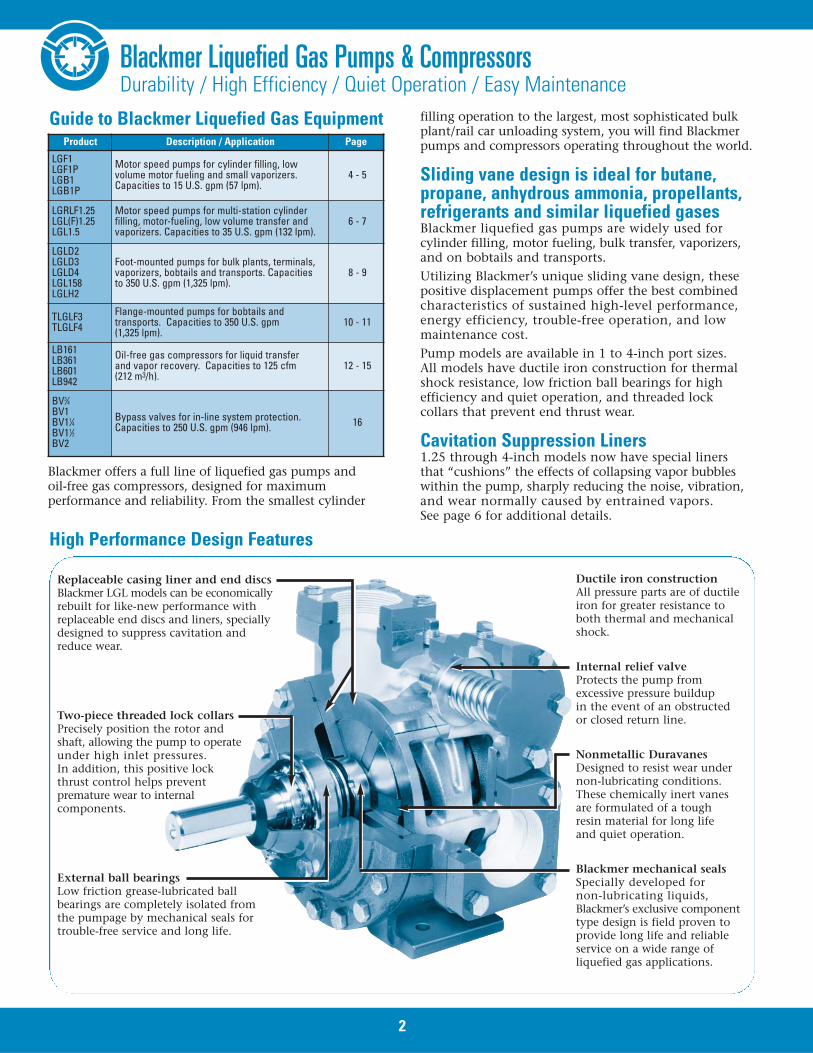
High Performance Design Features
Replaceable casing liner and end discsBlackmer LGL models can be economicallyrebuilt for like-new performance withreplaceable end discs and liners, speciallydesigned to suppress cavitation andreduce wear.
Two-piece threaded lock collarsPrecisely position the rotor and shaft, allowing the pump to operateunder high inlet pressures.In addition, this positive lock thrust control helps prevent premature wear to internalcomponents.
External ball bearings Low friction grease-lubricated ballbearings are completely isolated fromthe pumpage by mechanical seals fortrouble-free service and long life.
Ductile iron constructionAll pressure parts are of ductileiron for greater resistance toboth thermal and mechanicalshock.
Internal relief valve Protects the pump fromexcessive pressure buildupin the event of an obstructedor closed return line.
Nonmetallic Duravanes Designed to resist wear undernon-lubricating conditions.These chemically inert vanesare formulated of a toughresin material for long lifeand quiet operation.
Blackmer mechanical seals Specially developed fornon-lubricating liquids,Blackmer’s exclusive componenttype design is field proven toprovide long life and reliableservice on a wide range ofliquefied gas applications.
2
UL and ISO 9001All pump* and bypass valve models described in thisbulletin are listed by Underwriters Laboratories for bothLP-gas and anhydrous ammonia service. (*LGL158 andLGLH2 are listed for use on LP-gas service only.)All products in this bulletin are manufacturedto ISO 9001 quality standards.
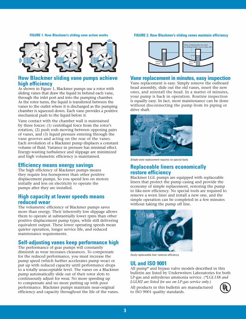
FIGURE 1. How Blackmer’s sliding vane action works
How Blackmer sliding vane pumps achievehigh efficiencyAs shown in Figure 1, Blackmer pumps use a rotor withsliding vanes that draw the liquid in behind each vane,through the inlet port and into the pumping chamber. As the rotor turns, the liquid is transferred between thevanes to the outlet where it is discharged as the pumpingchamber is squeezed down. Each vane provides a positivemechanical push to the liquid before it.Vane contact with the chamber wall is maintainedby three forces: (1) centrifugal force from the rotor’srotation, (2) push rods moving between opposing pairsof vanes, and (3) liquid pressure entering through thevane grooves and acting on the rear of the vanes. Each revolution of a Blackmer pump displaces a constantvolume of fluid. Variance in pressure has minimal effect.Energy-wasting turbulence and slippage are minimizedand high volumetric efficiency is maintained.
Efficiency means energy savingsThe high efficiency of Blackmer pumps means they require less horsepower than other positivedisplacement pumps. So you spend less on motorsinitially and less on electricity to operate the pumps after they are installed.
High capacity at lower speeds meansreduced wearThe volumetric efficiency of Blackmer pumps savesmore than energy. Their inherently low slippage allowsthem to operate at substantially lower rpms than otherpositive displacement pump types, while still deliveringequivalent output. These lower operating speeds meanquieter operation, longer service life, and reducedmaintenance requirements.
Self-adjusting vanes keep performance highThe performance of gear pumps will constantlydiminish as wear increases clearances. To compensatefor the reduced performance, you must increase thepump speed (which further accelerates pump wear) orput up with reduced capacity until performance dropsto a totally unacceptable level. The vanes on a Blackmerpump automatically slide out of their rotor slots tocontinuously adjust for wear. No more speeding upto compensate and no more putting up with poorperformance. Blackmer pumps maintain near-originalefficiency and capacity throughout the life of the vanes.
FIGURE 2. How Blackmer’s sliding vanes maintain efficiency
Vane replacement in minutes, easy inspectionVane replacement is easy. Simply remove the outboardhead assembly, slide out the old vanes, insert the newones, and reinstall the head. In a matter of minutes,your pump is back in operation. Routine inspection is equally easy. In fact, most maintenance can be donewithout disconnecting the pump from its piping ordrive shaft.
Simple vane replacement requires no special tools.
Replaceable liners economically restore efficiencyBlackmer LGL pumps are equipped with replaceableliners that protect the pump casing and provide theeconomy of simple replacement, restoring the pump to like-new efficiency. No special tools are required toremove a worn liner and install a new one, and thesimple operation can be completed in a few minuteswithout taking the pump off line.
New Vane
Worn Vane
Vane compensates for wear by sliding further out of rotor slot
3
Easily replaceable liner restores efficiency.
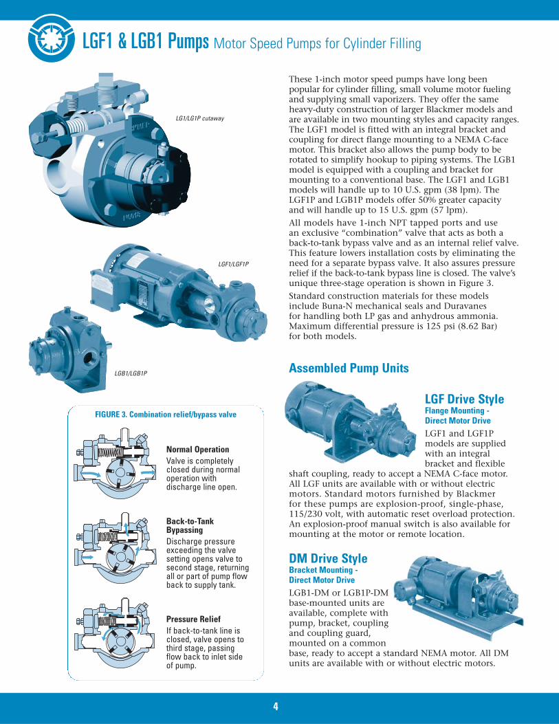
These 1-inch motor speed pumps have long beenpopular for cylinder filling, small volume motor fuelingand supplying small vaporizers. They offer the sameheavy-duty construction of larger Blackmer models andare available in two mounting styles and capacity ranges.The LGF1 model is fitted with an integral bracket andcoupling for direct flange mounting to a NEMA C-facemotor. This bracket also allows the pump body to berotated to simplify hookup to piping systems. The LGB1model is equipped with a coupling and bracket formounting to a conventional base. The LGF1 and LGB1models will handle up to 10 U.S. gpm (38 lpm). TheLGF1P and LGB1P models offer 50% greater capacityand will handle up to 15 U.S. gpm (57 lpm).All models have 1-inch NPT tapped ports and use an exclusive “combination” valve that acts as both aback-to-tank bypass valve and as an internal relief valve.This feature lowers installation costs by eliminating theneed for a separate bypass valve. It also assures pressurerelief if the back-to-tank bypass line is closed. The valve’sunique three-stage operation is shown in Figure 3.Standard construction materials for these modelsinclude Buna-N mechanical seals and Duravanes for handling both LP gas and anhydrous ammonia.Maximum differential pressure is 125 psi (8.62 Bar)for both models.
LGF1/LGF1P
FIGURE 3. Combination relief/bypass valve
LGF1 & LGB1 Pumps Motor Speed Pumps for Cylinder Filling
DM Drive StyleBracket Mounting - Direct Motor DriveLGB1-DM or LGB1P-DMbase-mounted units areavailable, complete withpump, bracket, couplingand coupling guard,mounted on a commonbase, ready to accept a standard NEMA motor. All DMunits are available with or without electric motors.
LGB1/LGB1P
Normal OperationValve is completelyclosed during normaloperation withdischarge line open.
Back-to-TankBypassingDischarge pressureexceeding the valvesetting opens valve tosecond stage, returningall or part of pump flowback to supply tank.
Pressure ReliefIf back-to-tank line isclosed, valve opens tothird stage, passing flow back to inlet side of pump.
LGF Drive StyleFlange Mounting - Direct Motor DriveLGF1 and LGF1Pmodels are suppliedwith an integralbracket and flexible
shaft coupling, ready to accept a NEMA C-face motor.All LGF units are available with or without electricmotors. Standard motors furnished by Blackmerfor these pumps are explosion-proof, single-phase,115/230 volt, with automatic reset overload protection.An explosion-proof manual switch is also available formounting at the motor or remote location.
Assembled Pump Units
4
LG1/LG1P cutaway
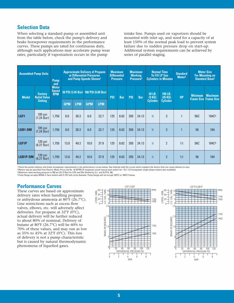
When selecting a standard pump or assembled unitfrom the table below, check the pump’s delivery andbrake horsepower requirements in the performancecurves. These pumps are rated for continuous duty,although such applications may accelerate pump wearrates, particularly if vaporization occurs in the pump
intake line. Pumps used on vaporizers should bemounted with inlet up, and sized for a capacity of atleast 150% of the normal peak load to prevent systemfailure due to sudden pressure drop on start-up.Additional system requirements can be achieved byseries of parallel staging.
Selection Data
Performance CurvesThese curves are based on approximatedelivery rates when handling propaneor anhydrous ammonia at 80°F (26.7°C).Line restrictions such as excess flowvalves, elbows, etc. will adversely affectdeliveries. For propane at 32°F (0°C),actual delivery will be further reduced to about 80% of nominal. Delivery ofbutane at 80°F (26.7°C) will be 60% to70% of these values, and may run as lowas 35% to 45% at 32°F (0°C). This lossof delivery is not a pump characteristicbut is caused by natural thermodynamicphenomena of liquefied gases.
0
0 2 4BAR
DIFFERENTIAL PRESSURE PSI
6 8
0
.5
1.0
1.5
2.000
20
40
60
5
10
15
20 40 60 80 100 120
LGF1P/LGB1PRPM
17501450
1750
1450
LITE
RS /
MIN
.
U.S.
GAL
/ M
IN.
BRAK
E HP
REQ
UIRE
D
Assembled Pump Units
Pumpand
MotorSpeedRPM
Approximate Delivery of Propaneat Differential Pressures
and Pump Speeds Shown1
MaximumDifferential
Pressure
Maximum Working
Pressure3
Normal Time To Fill LP Gas
Cylinders in MinutesStandard
Motor2
Motor SizeFor Mounting onStandard Base2
ModelFactory
Relief ValveSetting
50 PSI (3.45 Bar) 100 PSI (6.89 Bar)PSI Bar PSI Bar
20 LB. (9 KG)
Cylinder
100 LB. (45 KG)
CylinderHP Minimum
Frame SizeMaximum Frame Size
GPM LPM GPM LPM
LGF1 105 psi (7.24 Bar) 1,750 8.0 30.3 6.0 22.7 125 8.62 350 24.13 3⁄4 3 1 56C 184C4
LGB1-DM 105 psi (7.24 Bar) 1,750 8.0 30.3 6.0 22.7 125 8.62 350 24.13 3⁄4 3 1 56 184
LGF1P 120 psi (8.27 Bar) 1,750 13.0 49.2 10.0 37.9 125 8.62 350 24.13 1⁄2 2 11⁄2 56C 184C4
LGB1P-DM 120 psi (8.27 Bar) 1,750 13.0 49.2 10.0 37.9 125 8.62 350 24.13 1⁄2 2 11⁄2 56 184
1 Check the pump’s delivery and brake horsepower requirements in the performance curves below. See footnote with the curves which explains the factors that can cause delivery to vary.2 Motors may be specified from Electric Motor Price List No. 10-MTRG-01 (explosion-proof manual start switch for 1 & 1-1/2 horsepower single-phase motors also available).3 Maximum rated working pressure is 350 psi (24.13 Bar) for LPG and NH3 (limited by U.L. and N.F.P.A. 58).4 Pump flange accepts NEMA C-face motors with 5-7/8" bolt circle diameter. Pump flange will not accept 182TC or 184TC frames.
5
0
0 2 4BAR
DIFFERENTIAL PRESSURE PSI
6 8
0
.5
1.0
1.5
2.000
20
40
60
5
10
15
20 40 60 80 100 120
LGF1/LGB1RPM
17501450
1750
1450
LITE
RS /
MIN
.
U.S.
GAL
/ M
IN.
BRAK
E HP
REQ
UIRE
D
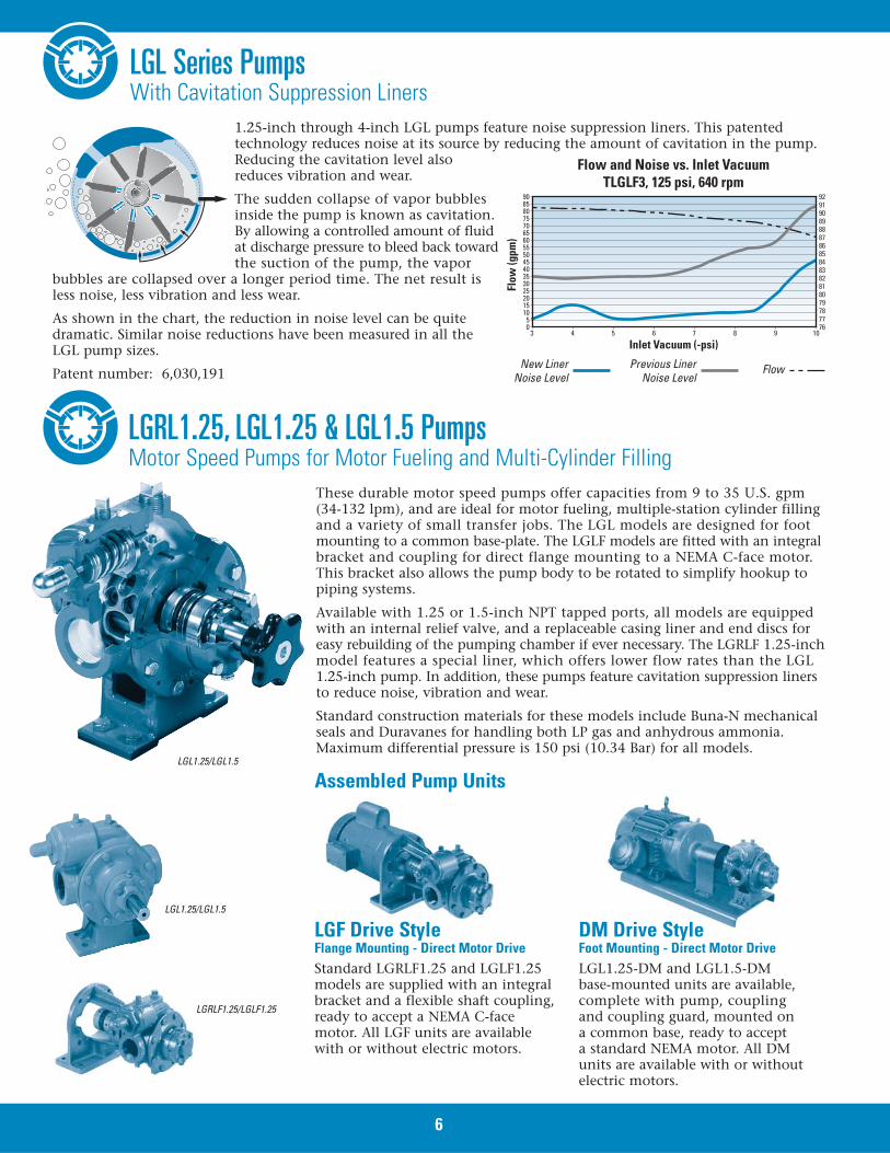
LGL Series PumpsWith Cavitation Suppression Liners
These durable motor speed pumps offer capacities from 9 to 35 U.S. gpm(34-132 lpm), and are ideal for motor fueling, multiple-station cylinder fillingand a variety of small transfer jobs. The LGL models are designed for footmounting to a common base-plate. The LGLF models are fitted with an integralbracket and coupling for direct flange mounting to a NEMA C-face motor.This bracket also allows the pump body to be rotated to simplify hookup topiping systems.
Available with 1.25 or 1.5-inch NPT tapped ports, all models are equippedwith an internal relief valve, and a replaceable casing liner and end discs foreasy rebuilding of the pumping chamber if ever necessary. The LGRLF 1.25-inchmodel features a special liner, which offers lower flow rates than the LGL1.25-inch pump. In addition, these pumps feature cavitation suppression linersto reduce noise, vibration and wear.
Standard construction materials for these models include Buna-N mechanicalseals and Duravanes for handling both LP gas and anhydrous ammonia.Maximum differential pressure is 150 psi (10.34 Bar) for all models.
1.25-inch through 4-inch LGL pumps feature noise suppression liners. This patentedtechnology reduces noise at its source by reducing the amount of cavitation in the pump.Reducing the cavitation level alsoreduces vibration and wear.
The sudden collapse of vapor bubblesinside the pump is known as cavitation.By allowing a controlled amount of fluidat discharge pressure to bleed back towardthe suction of the pump, the vapor
bubbles are collapsed over a longer period time. The net result isless noise, less vibration and less wear.
As shown in the chart, the reduction in noise level can be quitedramatic. Similar noise reductions have been measured in all theLGL pump sizes.
Patent number: 6,030,191
LGL1.25/LGL1.5
LGRLF1.25/LGLF1.25
LGL1.25/LGL1.5
Assembled Pump Units
LGF Drive StyleFlange Mounting - Direct Motor DriveStandard LGRLF1.25 and LGLF1.25models are supplied with an integralbracket and a flexible shaft coupling,ready to accept a NEMA C-facemotor. All LGF units are availablewith or without electric motors.
DM Drive StyleFoot Mounting - Direct Motor DriveLGL1.25-DM and LGL1.5-DMbase-mounted units are available,complete with pump, couplingand coupling guard, mounted ona common base, ready to accepta standard NEMA motor. All DMunits are available with or withoutelectric motors.
6
LGRL1.25, LGL1.25 & LGL1.5 PumpsMotor Speed Pumps for Motor Fueling and Multi-Cylinder Filling
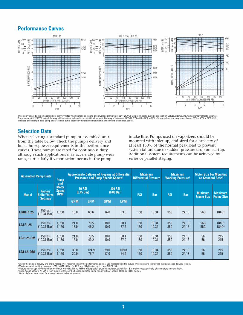
When selecting a standard pump or assembled unitfrom the table below, check the pump’s delivery andbrake horsepower requirements in the performancecurves. These pumps are rated for continuous duty,although such applications may accelerate pump wearrates, particularly if vaporization occurs in the pump
intake line. Pumps used on vaporizers should bemounted with inlet up, and sized for a capacity of at least 150% of the normal peak load to prevent system failure due to sudden pressure drop on startup.Additional system requirements can be achieved byseries or parallel staging.
Selection Data
Assembled Pump UnitsPumpand
MotorSpeed RPM
Approximate Delivery of Propane at DifferentialPressures and Pump Speeds Shown1
MaximumDifferential Pressure
MaximumWorking Pressure2
Motor Size For Mountingon Standard Base3
ModelFactory
Relief ValveSettings
50 PSI (3.45 Bar)
100 PSI (6.89 Bar)
PSI Bar PSI Bar MinimumFrame Size
MaximumFrame Size
GPM LPM GPM LPM
LGRLF1.25 150 psi (10.34 Bar) 1,750 16.0 60.6 14.0 53.0 150 10.34 350 24.13 56C 184C4
LGLF1.25 150 psi (10.34 Bar)
1,7501,150
21.013.0
79.549.2
18.010.0
68.137.9
150150
10.3410.34
350350
24.1324.13
56C56C
184C4
184C4
LGL1.25-DM 150 psi (10.34 Bar)
1,7501,150
21.013.0
79.549.2
18.010.0
68.137.9
150150
10.3410.34
350350
24.1324.13
5656
215215
LGL1.5-DM 150 psi (10.34 Bar)
1,7501,150
33.020.0
124.975.7
29.017.0
109.864.4
150150
10.3410.34
350350
24.1324.13
5656
215215
1 Check the pump’s delivery and brake horsepower requirements in the performance curves. See footnote with the curves which explains the factors that can cause delivery to vary.2 Maximum rated working pressure is 350 psi (24.13 Bar) for LPG and NH3 (limited by U.L. and N.F.P.A. 58).3 Motors may be specified from Electric Motor Price List No. 10-MTRG-01 (explosion-proof manual start switch for 1 & 1-1/2 horsepower single-phase motors also available).4 Pump flange accepts NEMA C-face motors with 5-7/8" bolt circle diameter. Pump flange will not accept 182TC or 184TC frames.
Note: Refer to back cover for external bypass valve information.
0
0 2 4 6 8 10BAR
DIFFERENTIAL PRESSURE PSI
0
1
2
3
4
500
40
80
120
10
20
30
20 40 60 80 100 120 140
LGRLF1.25RPM
17501450
1750
1450
LITE
RS /
MIN
.
U.S.
GAL
/ M
IN.
BRAK
E HP
REQ
UIRE
DPerformance Curves
These curves are based on approximate delivery rates when handling propane or anhydrous ammonia at 80°F (26.7°C). Line restrictions such as excess flow valves, elbows, etc. will adversely affect deliveries. For propane at 32°F (0°C), actual delivery will be further reduced to about 80% of nominal. Delivery of butane at 80°F (26.7°C) will be 60% to 70% of these values and may run as low as 35% to 45% at 32°F (0°C). This loss of delivery is not a pump characteristic but is caused by natural thermodynamic phenomena of liquefied gases.
7
0
0 2 4 6 8 10BAR
DIFFERENTIAL PRESSURE PSI
0
1
2
3
4
500
40
80
120
10
20
30
20 40 60 80 100 120 140
LGLF1.25 / LGL1.25RPM
175014501150
1750
1150
1450
LITE
RS /
MIN
.
U.S.
GAL
/ M
IN.
BRAK
E HP
REQ
UIRE
D0
0 2 4 6 8 10BAR
DIFFERENTIAL PRESSURE PSI
0
1
2
3
4
5520
60
100
140
15
25
35
20 40 60 80 100 120 140
LGL1.5RPM
1750
11501450
1750
1450
1150
LITE
RS /
MIN
.
U.S.
GAL
/ M
IN.
BRAK
E HP
REQ
UIRE
D
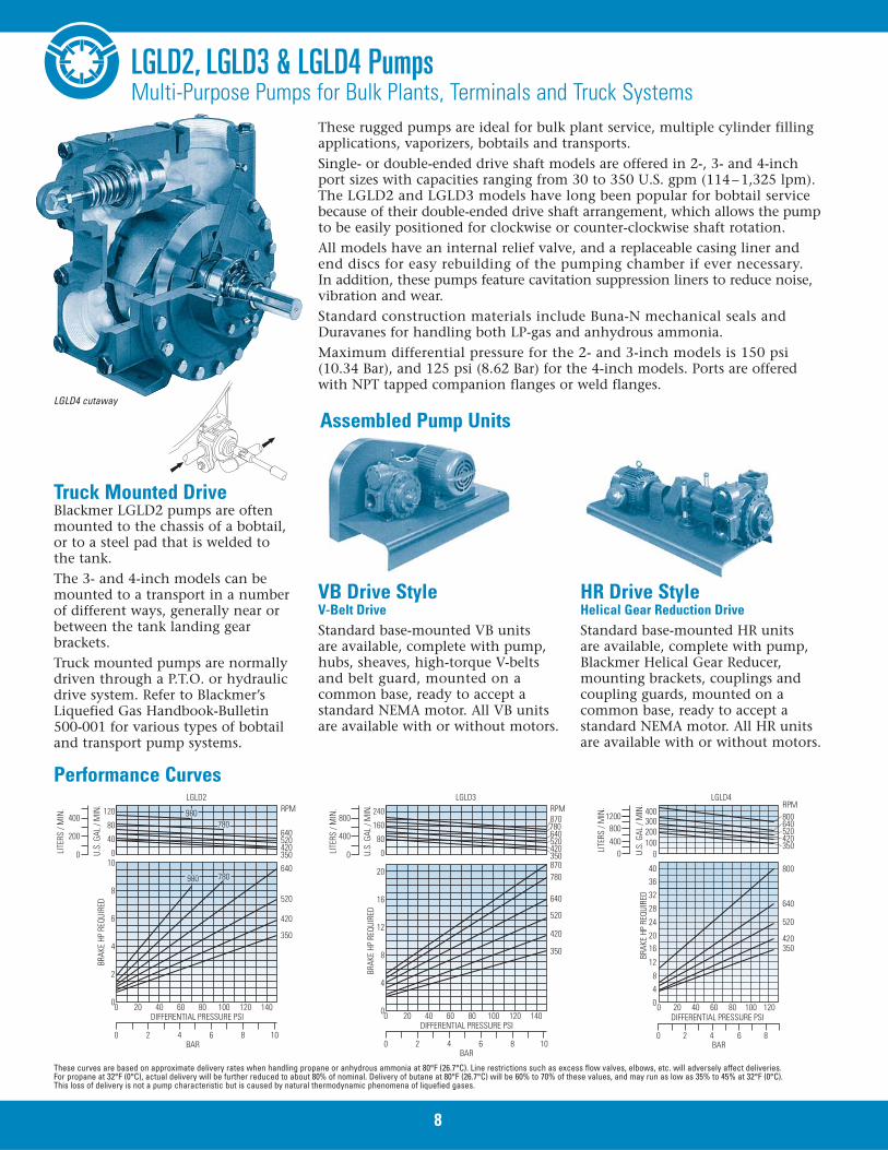
LGLD2, LGLD3 & LGLD4 PumpsMulti-Purpose Pumps for Bulk Plants, Terminals and Truck Systems
These rugged pumps are ideal for bulk plant service, multiple cylinder fillingapplications, vaporizers, bobtails and transports.Single- or double-ended drive shaft models are offered in 2-, 3- and 4-inchport sizes with capacities ranging from 30 to 350 U.S. gpm (114–1,325 lpm).The LGLD2 and LGLD3 models have long been popular for bobtail servicebecause of their double-ended drive shaft arrangement, which allows the pumpto be easily positioned for clockwise or counter-clockwise shaft rotation.All models have an internal relief valve, and a replaceable casing liner andend discs for easy rebuilding of the pumping chamber if ever necessary.In addition, these pumps feature cavitation suppression liners to reduce noise,vibration and wear.Standard construction materials include Buna-N mechanical seals andDuravanes for handling both LP-gas and anhydrous ammonia.Maximum differential pressure for the 2- and 3-inch models is 150 psi(10.34 Bar), and 125 psi (8.62 Bar) for the 4-inch models. Ports are offeredwith NPT tapped companion flanges or weld flanges.
0
0 2 4 6 8 10BAR
DIFFERENTIAL PRESSURE PSI
0
2
4
6
8
1000
200
400
40
80
120
20 40 60 80 100 120 140
LGLD2RPM
640520420350
350
420
520
640
780980
780980
LITE
RS /
MIN
.
U.S.
GAL
/ M
IN.
BRAK
E HP
REQ
UIRE
D
0
400
800
0
0 2 4 6 8 10BAR
DIFFERENTIAL PRESSURE PSI
0
4
8
12
16
20
0
80
160
240
20 40 60 80 100 120 140
LGLD3RPM
640520420350
350
420
520
640
780
780870
870
LITE
RS /
MIN
.
U.S.
GAL
/ M
IN.
BRAK
E HP
REQ
UIRE
D
LGLD4
0 2 4BAR
DIFFERENTIAL PRESSURE PSI
6 8
0 20 40 60 80 100 120
350
520
420
640
800
0
4
8
12
1620
24
28
32
3640
BRAK
E HP
REQ
UIRE
D
RPM800640520420350
00400800
1200
100200300400
LITE
RS /
MIN
.
U.S.
GAL
/ M
IN.
Performance Curves
These curves are based on approximate delivery rates when handling propane or anhydrous ammonia at 80°F (26.7°C). Line restrictions such as excess flow valves, elbows, etc. will adversely affect deliveries. For propane at 32°F (0°C), actual delivery will be further reduced to about 80% of nominal. Delivery of butane at 80°F (26.7°C) will be 60% to 70% of these values, and may run as low as 35% to 45% at 32°F (0°C). This loss of delivery is not a pump characteristic but is caused by natural thermodynamic phenomena of liquefied gases.
Truck Mounted DriveBlackmer LGLD2 pumps are oftenmounted to the chassis of a bobtail,or to a steel pad that is welded to the tank.The 3- and 4-inch models can bemounted to a transport in a numberof different ways, generally near orbetween the tank landing gearbrackets.Truck mounted pumps are normallydriven through a P.T.O. or hydraulicdrive system. Refer to Blackmer’sLiquefied Gas Handbook-Bulletin 500-001 for various types of bobtailand transport pump systems.
VB Drive StyleV-Belt DriveStandard base-mounted VB units are available, complete with pump,hubs, sheaves, high-torque V-beltsand belt guard, mounted on acommon base, ready to accept astandard NEMA motor. All VB unitsare available with or without motors.
HR Drive StyleHelical Gear Reduction DriveStandard base-mounted HR units are available, complete with pump,Blackmer Helical Gear Reducer,mounting brackets, couplings andcoupling guards, mounted on acommon base, ready to accept astandard NEMA motor. All HR unitsare available with or without motors.
Assembled Pump UnitsLGLD4 cutaway
8
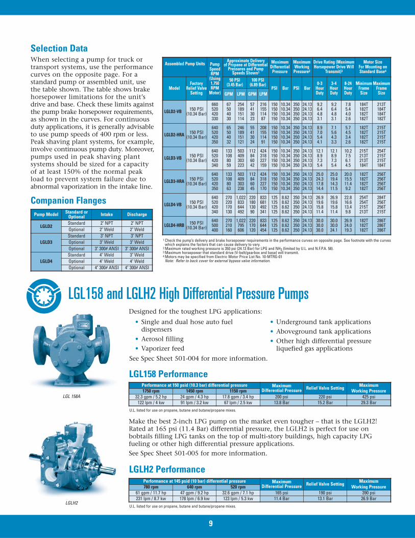
When selecting a pump for truck ortransport systems, use the performancecurves on the opposite page. For astandard pump or assembled unit, usethe table shown. The table shows brakehorsepower limitations for the unit’sdrive and base. Check these limits againstthe pump brake horsepower requirements,as shown in the curves. For continuousduty applications, it is generally advisableto use pump speeds of 400 rpm or less.Peak shaving plant systems, for example,involve continuous pump duty. Moreover,pumps used in peak shaving plantsystems should be sized for a capacityof at least 150% of the normal peakload to prevent system failure due toabnormal vaporization in the intake line.
Selection Data
Pump Model Standard orOptional Intake Discharge
LGLD2Standard 2" NPT 2" NPTOptional 2" Weld 2" Weld
LGLD3Standard 3" NPT 3" NPTOptional 3" Weld 3" WeldOptional 3" 300# ANSI 3" 300# ANSI
LGLD4Standard 4" Weld 3" WeldOptional 4" Weld 4" WeldOptional 4" 300# ANSI 4" 300# ANSI
Companion Flanges
LGL158 Performance
Assembled Pump Units PumpSpeedRPM
(Using1,750RPM
Motor)
Approximate Delivery of Propane at Differential
Pressures and PumpSpeeds Shown1
MaximumDifferential
Pressure
Maximum Working
Pressure2
Drive Rating (MaximumHorsepower Drive Will
Transmit)3
Motor SizeFor Mounting onStandard Base4
ModelFactory
Relief ValveSetting
50 PSI(3.45 Bar)
100 PSI(6.89 Bar)
PSI Bar PSI Bar0-3
HourDuty
3-4HourDuty
8-24HourDuty
MinimumFrameSize
Maximum FrameSizeGPM LPM GPM LPM
LGLD2-VB 150 PSI(10.34 Bar)
660520420330
67504030
254189151114
57413023
21615511487
150150150150
10.3410.3410.3410.34
350350350350
24.1324.1324.1324.13
9.26.44.83.1
9.26.44.83.1
7.85.44.02.6
184T182T182T182T
213T184T184T182T
LGLD2-HRA 150 PSI(10.34 Bar)
640520420350
65504032
246189151121
55413024
20815511491
150150150150
10.3410.3410.3410.34
350350350350
24.1324.1324.1324.13
8.97.05.44.1
7.15.64.33.3
5.74.53.42.6
182T182T182T182T
215T215T215T215T
LGLD3-VB 150 PSI(10.34 Bar)
640520420340
1331088059
503409303223
112846042
424318227159
150150150150
10.3410.3410.3410.34
350350350350
24.1324.1324.1324.13
12.18.97.35.4
12.18.97.35.4
10.27.56.14.5
215T213T213T184T
254T215T215T184T
LGLD3-HRA 150 PSI(10.34 Bar)
640520420350
1331088063
503409303238
112846045
424318227170
150150150150
10.3410.3410.3410.34
350350350350
24.1324.1324.1324.13
25.024.317.814.4
25.019.414.311.5
20.015.511.49.2
182T182T182T182T
256T256T256T256T
LGLD4-VB 150 PSI(10.34 Bar)
640520420340
270220170130
1,022833644492
22018013090
833681492341
125125125125
8.628.628.628.62
350350350350
24.1324.1324.1324.13
26.919.615.811.4
26.919.615.811.4
22.816.613.49.8
254T254T215T213T
284T256T256T215T
LGLD4-HRB 150 PSI(10.34 Bar)
640500400
270210160
1,022795606
220170120
833644454
125125125
8.628.628.62
350350350
24.1324.1324.13
30.030.030.0
30.030.024.1
26.924.019.3
182T182T182T
286T286T286T
1 Check the pump’s delivery and brake horsepower requirements in the performance curves on opposite page. See footnote with the curveswhich explains the factors that can cause delivery to vary.
2 Maximum rated working pressure is 350 psi (24.13 Bar) for LPG and NH3 (limited by U.L. and N.F.P.A. 58).3 Maximum horsepower that standard drive (V-belt/gearbox and base) will transmit.4 Motors may be specified from Electric Motor Price List No. 10-MTRG-01
Note: Refer to back cover for external bypass valve information.
9
Performance at 150 psid (10.3 bar) differential pressure MaximumDifferential Pressure Relief Valve Setting Maximum
Working Pressure1750 rpm 1450 rpm 1150 rpm32.3 gpm / 5.2 hp 24 gpm / 4.3 hp 17.8 gpm / 3.4 hp 200 psi 220 psi 425 psi
122 lpm / 4 kw 91 lpm / 3.2 kw 67 lpm / 2.5 kw 13.8 Bar 15.2 Bar 29.3 Bar
Designed for the toughest LPG applications:
• Single and dual hose auto fueldispensers
• Aerosol filling• Vaporizer feed
• Underground tank applications• Aboveground tank applications• Other high differential pressure
liquefied gas applications
See Spec Sheet 501-004 for more information.
LGLH2 PerformancePerformance at 145 psid (10 bar) differential pressure Maximum
Differential Pressure Relief Valve Setting MaximumWorking Pressure780 rpm 640 rpm 520 rpm
61 gpm / 11.7 hp 47 gpm / 9.2 hp 32.6 gpm / 7.1 hp 165 psi 190 psi 390 psi231 lpm / 8.7 kw 178 lpm / 6.9 kw 123 lpm / 5.3 kw 11.4 Bar 13.1 Bar 26.9 Bar
Make the best 2-inch LPG pump on the market even tougher – that is the LGLH2!Rated at 165 psi (11.4 Bar) differential pressure, the LGLH2 is perfect for use onbobtails filling LPG tanks on the top of multi-story buildings, high capacity LPGfueling or other high differential pressure applications.See Spec Sheet 501-005 for more information.
LGL 158A
LGLH2
U.L. listed for use on propane, butane and butane/propane mixes.
U.L. listed for use on propane, butane and butane/propane mixes.
LGL158 and LGLH2 High Differential Pressure Pumps
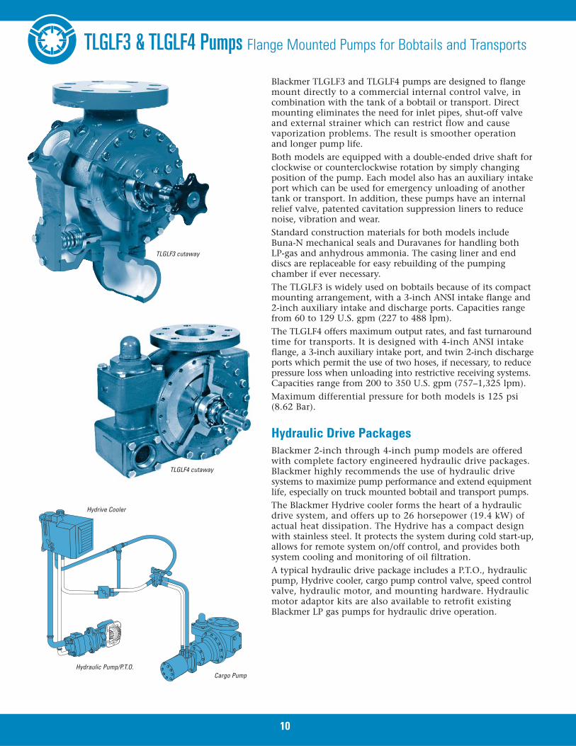
TLGLF3 & TLGLF4 Pumps Flange Mounted Pumps for Bobtails and Transports
Blackmer TLGLF3 and TLGLF4 pumps are designed to flangemount directly to a commercial internal control valve, incombination with the tank of a bobtail or transport. Directmounting eliminates the need for inlet pipes, shut-off valveand external strainer which can restrict flow and causevaporization problems. The result is smoother operationand longer pump life.Both models are equipped with a double-ended drive shaft forclockwise or counterclockwise rotation by simply changingposition of the pump. Each model also has an auxiliary intakeport which can be used for emergency unloading of anothertank or transport. In addition, these pumps have an internalrelief valve, patented cavitation suppression liners to reducenoise, vibration and wear.Standard construction materials for both models includeBuna-N mechanical seals and Duravanes for handling bothLP-gas and anhydrous ammonia. The casing liner and enddiscs are replaceable for easy rebuilding of the pumpingchamber if ever necessary.The TLGLF3 is widely used on bobtails because of its compactmounting arrangement, with a 3-inch ANSI intake flange and2-inch auxiliary intake and discharge ports. Capacities rangefrom 60 to 129 U.S. gpm (227 to 488 lpm).The TLGLF4 offers maximum output rates, and fast turnaroundtime for transports. It is designed with 4-inch ANSI intakeflange, a 3-inch auxiliary intake port, and twin 2-inch dischargeports which permit the use of two hoses, if necessary, to reducepressure loss when unloading into restrictive receiving systems.Capacities range from 200 to 350 U.S. gpm (757–1,325 lpm).Maximum differential pressure for both models is 125 psi(8.62 Bar).
Blackmer 2-inch through 4-inch pump models are offeredwith complete factory engineered hydraulic drive packages.Blackmer highly recommends the use of hydraulic drivesystems to maximize pump performance and extend equipmentlife, especially on truck mounted bobtail and transport pumps.The Blackmer Hydrive cooler forms the heart of a hydraulicdrive system, and offers up to 26 horsepower (19.4 kW) ofactual heat dissipation. The Hydrive has a compact designwith stainless steel. It protects the system during cold start-up,allows for remote system on/off control, and provides bothsystem cooling and monitoring of oil filtration.A typical hydraulic drive package includes a P.T.O., hydraulicpump, Hydrive cooler, cargo pump control valve, speed controlvalve, hydraulic motor, and mounting hardware. Hydraulicmotor adaptor kits are also available to retrofit existingBlackmer LP gas pumps for hydraulic drive operation.
TLGLF3 cutaway
Hydraulic Drive Packages
TLGLF4 cutaway
Cargo PumpHydraulic Pump/P.T.O.
Hydrive Cooler
10
11
TLGLF3 TLGLF4
0 2 4BAR
DIFFERENTIAL PRESSURE PSI
6 8
0
4
2
6
8
10
12
0 20 40 60 80 100 120
400
500
600650800
870
BRAK
E HP
REQ
UIRE
D
RPM87080065060050040000
200100
300400500
4080
120160
LITE
RS /
MIN
.
U.S.
GAL
/ M
IN.
0 2 4BAR
DIFFERENTIAL PRESSURE PSI
6 8
0 20 40 60 80 100 120
350
520
420
640
800
0
4
8
12
16
20
24
28
32
36
40
BRAK
E HP
REQ
UIRE
D
RPM
800640520420350
00
400
800
1200
100200300400
LITE
RS /
MIN
.
U.S.
GAL
/ M
IN.
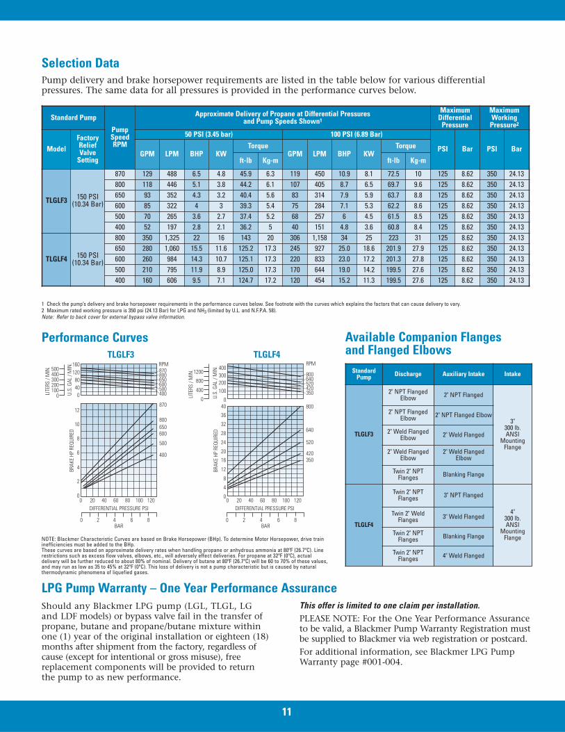
Performance CurvesTLGLF3 TLGLF4
Selection DataPump delivery and brake horsepower requirements are listed in the table below for various differential pressures. The same data for all pressures is provided in the performance curves below.
Available Companion Flangesand Flanged Elbows
NOTE: Blackmer Characteristic Curves are based on Brake Horsepower (BHp). To determine Motor Horsepower, drive traininefficiencies must be added to the BHp.These curves are based on approximate delivery rates when handling propane or anhydrous ammonia at 80ºF (26.7ºC). Linerestrictions such as excess flow valves, elbows, etc., will adversely effect deliveries. For propane at 32ºF (0ºC), actualdelivery will be further reduced to about 80% of nominal. Delivery of butane at 80ºF (26.7ºC) will be 60 to 70% of these values,and may run as low as 35 to 45% at 32ºF (0ºC). This loss of delivery is not a pump characteristic but is caused by naturalthermodynamic phenomena of liquefied gases.
1 Check the pump’s delivery and brake horsepower requirements in the performance curves below. See footnote with the curves which explains the factors that can cause delivery to vary.2 Maximum rated working pressure is 350 psi (24.13 Bar) for LPG and NH3 (limited by U.L. and N.F.P.A. 58).Note: Refer to back cover for external bypass valve information.
Standard Pump
PumpSpeedRPM
Approximate Delivery of Propane at Differential Pressures and Pump Speeds Shown1
MaximumDifferential
Pressure
MaximumWorking
Pressure2
ModelFactoryReliefValve
Setting
50 PSI (3.45 bar) 100 PSI (6.89 Bar)
PSI Bar PSI BarGPM LPM BHP KW
TorqueGPM LPM BHP KW
Torque
ft-lb Kg-m ft-lb Kg-m
TLGLF3 150 PSI(10.34 Bar)
870 129 488 6.5 4.8 45.9 6.3 119 450 10.9 8.1 72.5 10 125 8.62 350 24.13800 118 446 5.1 3.8 44.2 6.1 107 405 8.7 6.5 69.7 9.6 125 8.62 350 24.13650 93 352 4.3 3.2 40.4 5.6 83 314 7.9 5.9 63.7 8.8 125 8.62 350 24.13600 85 322 4 3 39.3 5.4 75 284 7.1 5.3 62.2 8.6 125 8.62 350 24.13500 70 265 3.6 2.7 37.4 5.2 68 257 6 4.5 61.5 8.5 125 8.62 350 24.13400 52 197 2.8 2.1 36.2 5 40 151 4.8 3.6 60.8 8.4 125 8.62 350 24.13
TLGLF4 150 PSI(10.34 Bar)
800 350 1,325 22 16 143 20 306 1,158 34 25 223 31 125 8.62 350 24.13650 280 1,060 15.5 11.6 125.2 17.3 245 927 25.0 18.6 201.9 27.9 125 8.62 350 24.13600 260 984 14.3 10.7 125.1 17.3 220 833 23.0 17.2 201.3 27.8 125 8.62 350 24.13500 210 795 11.9 8.9 125.0 17.3 170 644 19.0 14.2 199.5 27.6 125 8.62 350 24.13400 160 606 9.5 7.1 124.7 17.2 120 454 15.2 11.3 199.5 27.6 125 8.62 350 24.13
StandardPump Discharge Auxiliary Intake Intake
TLGLF3
2" NPT FlangedElbow 2" NPT Flanged
3"300 lb.ANSI
MountingFlange
2" NPT FlangedElbow 2" NPT Flanged Elbow
2" Weld FlangedElbow 2" Weld Flanged
2" Weld FlangedElbow
2" Weld FlangedElbow
Twin 2" NPTFlanges Blanking Flange
TLGLF4
Twin 2" NPTFlanges 3" NPT Flanged
4" 300 lb.ANSI
MountingFlange
Twin 2" WeldFlanges 3" Weld Flanged
Twin 2" NPTFlanges Blanking Flange
Twin 2" NPTFlanges 4" Weld Flanged
Should any Blackmer LPG pump (LGL, TLGL, LGand LDF models) or bypass valve fail in the transfer ofpropane, butane and propane/butane mixture withinone (1) year of the original installation or eighteen (18)months after shipment from the factory, regardless ofcause (except for intentional or gross misuse), freereplacement components will be provided to returnthe pump to as new performance.
LPG Pump Warranty – One Year Performance AssuranceThis offer is limited to one claim per installation.PLEASE NOTE: For the One Year Performance Assuranceto be valid, a Blackmer Pump Warranty Registration mustbe supplied to Blackmer via web registration or postcard. For additional information, see Blackmer LPG PumpWarranty page #001-004.
LB161, LB361, LB601 & LB942 CompressorsOil-Free Gas Compressors for Liquid Transfer and Vapor Recovery
Blackmer oil-free gas compressors deliver highefficiency in handling propane, butane, anhydrousammonia and other liquefied gases. They are idealfor rail car unloading and vapor recovery applications.The single-stage, reciprocating compressors aredesigned to give maximum performance and reliabilityunder the most severe service conditions. All pressureparts are of ductile iron construction for greaterresistance to both thermal and mechanical shock.They are designed for ease of maintenance, with allcomponents readily accessible.
Models are available with capacities from 7 to 125 cfm(11.9 to 212 m3/h) with working pressure up to425 psia (29.31 Bar).
Gas compressors for liquid transferMany liquid transfer applications can be handled moreefficiently with a gas compressor than a liquid pump.They include unloading of transports and pressurevessels where system piping restricts flow and maycause a pump to cavitate; unloading of LP gas fromrail cars, and other installations that require aninitial lift to the liquid.
How liquid transfer is accomplishedWhen transferring liquid, a compressor creates aslight pressure differential between the vessel beingunloaded and the receiving tank. The suction strokeof the compressor piston draws in vapor and decreasesthe receiving tank pressure. The discharge stroke movesa measured volume of vapor at a higher pressure intothe supply tank where it displaces an equal volume ofliquid through a separate line into the receiving tank.Generally, the liquid flow rate will be 5 to 6 U.S. gpmfor each cubic foot (ft3) of piston displacement(670 - 775 liters per cubic meter [m3]).
Gas compressors for vapor recoveryWhen the liquid transfer phase has been completed,a significant amount of product (vapor and liquid) is left in the tank car (often 3% or more of the tank’scapacity). Recovery of product with a compressoris a simple operation, and thus a compressor canquickly pay for itself.
How vapor recovery is accomplishedVapor recovery is accomplished with the use ofa four-way valve. By rotating the valve handle 90°,gas flow is reversed and the vapor pressure withinthe supply vessel is reduced. At this point, remainingliquid vaporizes and is quickly recovered. As thetank pressure is drawn down further, remainingvapors are also recovered to an economical level.Recovered vapor is discharged into the liquid areaof the receiving tank and then condensed back intoa liquid state.
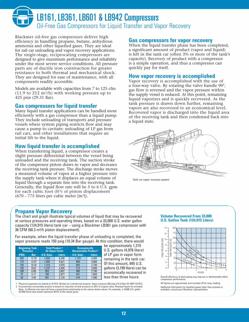
Propane Vapor RecoveryThe chart and graph illustrate typical volumes of liquid that may be recovered at various pressures and operating times, based on a 33,000 U.S. water galloncapacity (124,915 liters) tank car – using a Blackmer LB361 gas compressor with36 CFM (60.3 m3/h piston displacement).
For example, when the liquid transfer phase of unloading is completed, thevapor pressure reads 150 psig (10.34 Bar gauge). At this condition, there would
be approximately 1,315U.S. gallons (4,978 liters)of LP gas in vapor formremaining in the tank car.Of this amount, 845 U.S.gallons (3,199 liters) can beeconomically recovered inless than three hours.
Volume Recovered From 33,000 U.S. Gallon Tank (124,915 Liters)
Overall efficiency of plant piping may improve or detrimentally affect compressor performance.
All figures are approximate and rounded off for easy reading.
Additional information for liquefied gases other than propane is available: consult your Blackmer representative.
Beginning TankPressure
Total Product 1(In Vapor Form)
Economically Recoverable Product 2
PSIG Bar U.S. Gals. Liters U.S. Gals. Liters200 13.79 1,650 6,246 1,153 4,365175 12.07 1,485 5,621 969 3,668150 10.34 1,315 4,978 845 3,199125 8.62 1,137 4,304 713 2,699100 6.89 953 3,607 580 2,19675 5.17 760 2,877 441 1,66950 3.45 561 2,124 419 1,586
1,153 (43.65)
419 (15.86)
580 (21.90)
845 (31.99)
0HOURS
0
125
100
75
50
25
150
175
200
0
10
8
6
4
2
12
14
1 2 3 4 5
TAN
K PR
ESSU
RE P
SI
TAN
K PR
ESSU
RE B
AR
1 Physical properties are based on N.F.P.A. 58 data for commercial propane. Vapor pressure 205 psig (14.13 Bar) @ 100ºF (37.8ºC).2 Economically recoverable product is based on reduction of tank pressure to 25% of original value. Residual liquid not included.
Note: A different size tank will have a proportional relationship to the values shown above. For example, a 10,000 U.S. gallon (27,850 liters) tank would represent 30.3% of the values given.
Tank car vapor recovery system
12
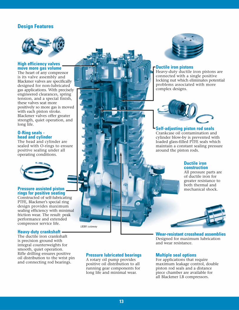
High efficiency valves move more gas volumeThe heart of any compressoris its valve assembly andBlackmer valves are specificallydesigned for non-lubricated gas applications. With preciselyengineered clearances, springtension, and a special finish,these valves seat morepositively so more gas is movedwith each piston stroke.Blackmer valves offer greaterstrength, quiet operation, andlong life.
O-Ring seals - head and cylinderThe head and cylinder aresealed with O-rings to ensurepositive sealing under alloperating conditions.
Pressure assisted piston rings for positive seatingConstructed of self-lubricating PTFE, Blackmer’s special ringdesign provides maximumsealing efficiency with minimalfriction wear. The result: peakperformance and extendedcompressor service life.
Heavy-duty crankshaftThe ductile iron crankshaft is precision ground with integral counterweights forsmooth, quiet operation. Rifle drilling ensures positive oil distribution to the wrist pinand connecting rod bearings.
Pressure lubricated bearingsA rotary oil pump provides positive oil distribution to allrunning gear components forlong life and minimal wear.
13
Ductile iron pistonsHeavy-duty ductile iron pistons areconnected with a single positivelocking nut which eliminates potentialproblems associated with morecomplex designs.
LB361 cutaway
Self-adjusting piston rod sealsCrankcase oil contamination andcylinder blow-by is prevented withloaded glass-filled PTFE seals whichmaintain a constant sealing pressurearound the piston rods.
Ductile ironconstructionAll pressure parts areof ductile iron forgreater resistance toboth thermal andmechanical shock.
Wear-resistant crosshead assembliesDesigned for maximum lubricationand wear resistance.
Multiple seal optionsFor applications that requiremaximum leakage control, doublepiston rod seals and a distancepiece chamber are available forall Blackmer LB compressors.
Design Features
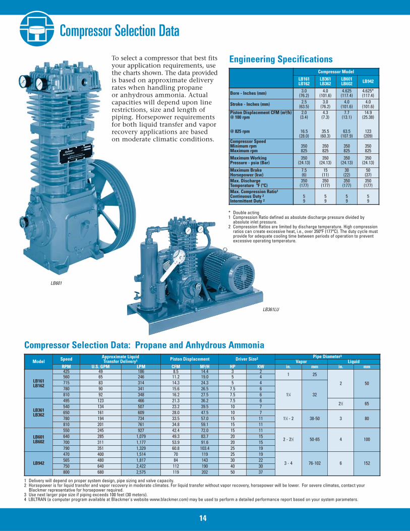
Compressor Selection Data
To select a compressor that best fitsyour application requirements, usethe charts shown. The data providedis based on approximate deliveryrates when handling propaneor anhydrous ammonia. Actualcapacities will depend upon linerestrictions, size and length ofpiping. Horsepower requirementsfor both liquid transfer and vaporrecovery applications are basedon moderate climatic conditions.
Model Speed Approximate LiquidTransfer Delivery1 Piston Displacement Driver Size2 Pipe Diameter3
Vapor LiquidRPM U.S. GPM LPM CFM M3/H HP KW in. mm in. mm
LB161LB162
425 49 186 8.5 14.4 3 21 25
2 50560 65 246 11.2 19.0 5 4715 83 314 14.3 24.3 5 4
11⁄4 32780 90 341 15.6 26.5 7.5 6810 92 348 16.2 27.5 7.5 6
LB361LB362
495 123 466 21.3 36.2 7.5 621⁄2 65
540 134 507 23.2 39.5 10 7650 161 609 28.0 47.5 10 7
11⁄2 - 2 38-50 3 80780 194 734 33.5 57.0 15 11810 201 761 34.8 59.1 15 11
LB601LB602
550 245 927 42.4 72.0 15 11
2 - 21⁄2 50-65 4 100640 285 1,079 49.3 83.7 20 15700 311 1,177 53.9 91.6 20 15790 351 1,329 60.8 103.4 25 19
LB942
470 400 1,514 70 119 25 19
3 - 4 76-102 6 152565 480 1,817 84 143 30 22750 640 2,422 112 190 40 30800 680 2,575 119 202 50 37
Compressor Model
LB161LB162
LB361LB362
LB601LB602 LB942
Bore - Inches (mm) 3.0(76.2)
4.0(101.6)
4.625(117.4)
4.625*(117.4)
Stroke - Inches (mm) 2.5(63.5)
3.0(76.2)
4.0(101.6)
4.0(101.6)
Piston Displacement CFM (m3/h)@ 100 rpm
@ 825 rpm
2.0(3.4)
16.5(28.0)
4.3(7.3)
35.5(60.3)
7.7(13.1)
63.5(107.9)
14.9(25.38)
123(209)
Compressor SpeedMinimum rpmMaximum rpm
350825
350825
350825
350825
Maximum WorkingPressure - psia (Bar)
350(24.13)
350(24.13)
350(24.13)
350(24.13)
Maximum BrakeHorsepower (kw)
7.5(6)
15(11)
30(22)
50(37)
Max. DischargeTemperature ºF (ºC)
350(177)
350(177)
350(177)
350(177)
Max. Compression Ratio1
Continuous Duty 2Intermittent Duty 2
59
59
59
59
1 Delivery will depend on proper system design, pipe sizing and valve capacity.2 Horsepower is for liquid transfer and vapor recovery in moderate climates. For liquid transfer without vapor recovery, horsepower will be lower. For severe climates, contact your
Blackmer representative for horsepower required. 3 Use next larger pipe size if piping exceeds 100 feet (30 meters).4 LBLTRAN (a computer program available at Blackmer's website www.blackmer.com) may be used to perform a detailed performance report based on your system parameters.
Engineering Specifications
Compressor Selection Data: Propane and Anhydrous Ammonia
* Double acting1 Compression Ratio defined as absolute discharge pressure divided by
absolute inlet pressure.2 Compression Ratios are limited by discharge temperature. High compression
ratios can create excessive heat, i.e., over 350ºF (177ºC). The duty cycle mustprovide for adequate cooling time between periods of operation to preventexcessive operating temperature.
LB601
LB361LU
14
HD Series CompressorsBlackmer also offers a line of single and two-stageindustrial gas compressors with double or triple pistonrod seals and air or water cooling. Consult your Blackmerrepresentative for more information and specifications.
Optional AccessoriesMotors: Standard voltage and sizes in stock.Motor slide rails: Offer easy adjustment for standardmotor frame sizes.Engines: Diesel, propane or gasoline fueled enginesavailable.Liquid traps: Standard liquid traps have amechanical float to protect the compressor bypreventing liquid from entering. These trapsmay be fitted with an electric float switch tosound an alarm or stop the compressor in theevent of high liquid level. Larger traps withASME code construction and one or twoelectric float switches are also available.
Vapor strainer assembly: Features a 30-meshreplaceable stainless steel screen and ductileiron body.Four-way valve: Four-way valvesallow easy switching from liquidtransfer to vapor recovery operation
by reversing the system flow direction.Standard valves are ductile iron with ahandle and easy-to-read flow direction indicator.Valves with electric or pneumatic actuation are availableif remote operation is desired.
Pressure gauges: Standard 1⁄4-inch NPTliquid-filled for head mounting.Extended crankshaft: For direct drive mounting,or V-belt drive applications.
Base plates: Formed steel or fabricated skid type.Belt guards: Heavy-duty 14-gauge steel, stainless steelor non-sparking aluminum construction.
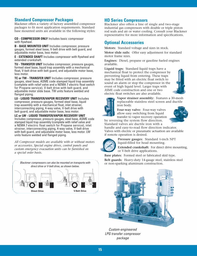
Standard Compressor PackagesBlackmer offers a variety of factory assembled compressorpackages to fit most application requirements. Standardbase mounted units are available in the following styles:
CO - COMPRESSOR ONLY Includes basic compressor with flywheel.B - BASE MOUNTED UNIT Includes compressor, pressuregauges, formed steel base, V-belt drive with belt guard, andadjustable motor base, less motor.E - EXTENDED SHAFT Includes compressor with flywheel andextended crankshaft.TU - TRANSFER UNIT Includes compressor, pressure gauges,formed steel base, liquid trap assembly with a mechanicalfloat, V-belt drive with belt guard, and adjustable motor base,less motor.TC or TW - TRANSFER UNIT Includes compressor, pressuregauges, steel base, ASME code stamped liquid trap assembly(complete with relief valve and a NEMA 7 electric float switchfor Propane service), V-belt drive with belt guard, andadjustable motor slide base. TW units feature welded andflanged piping.LU - LIQUID TRANSFER/VAPOR RECOVERY UNIT Includes compressor, pressure gauges, formed steel base, liquidtrap assembly with a mechanical float, inlet strainer,interconnecting piping, 4-way valve, V-belt drive withbelt guard, and adjustable motor base, less motor.LC or LW - LIQUID TRANSFER/VAPOR RECOVERY UNITIncludes compressor, pressure gauges, steel base, ASME codestamped liquid trap assembly (complete with relief valve anda NEMA 7 electric float switch for Propane service), inletstrainer, interconnecting piping, 4-way valve, V-belt drivewith belt guard, and adjustable motor base, less motor. LWunits feature welded and flanged piping.
All Compressor models are available with or without motorsor accessories. Special engine drives, control panels andcustom emergency evacuation units can be furnished ona special order basis.
V-Belt DriveDirect Drive
Blackmer compressors can also be mounted on transports withdirect drive or V-belt drive, as shown below.
15
Custom-engineeredLPG transfer compressor
package
www.blackmer.com
90 95 100 1050
25
50
75
100
125
BYPA
SS F
LOW
(GPM
)
DIFFERENTIAL PRESSURE SETTING (PSI)
BV 3⁄4 /BV1 BV2 cutawayBV2
Dash-pot chamber cushionsclosing of valve
www.blackmer.com
World Headquarters1809 Century Avenue SW
Grand Rapids, MI 49503-1530 USAT 616.241.1611 F 616.241.3752
European HeadquartersZl Plaine des Isles, 2 rue des Caillottes
89000 Auxerre, FRANCET +33.3.86.49.86.30 F +33.3.86.46.42.10Printed in USA 03/08 -2M © 2008 Blackmer
Distributed by:
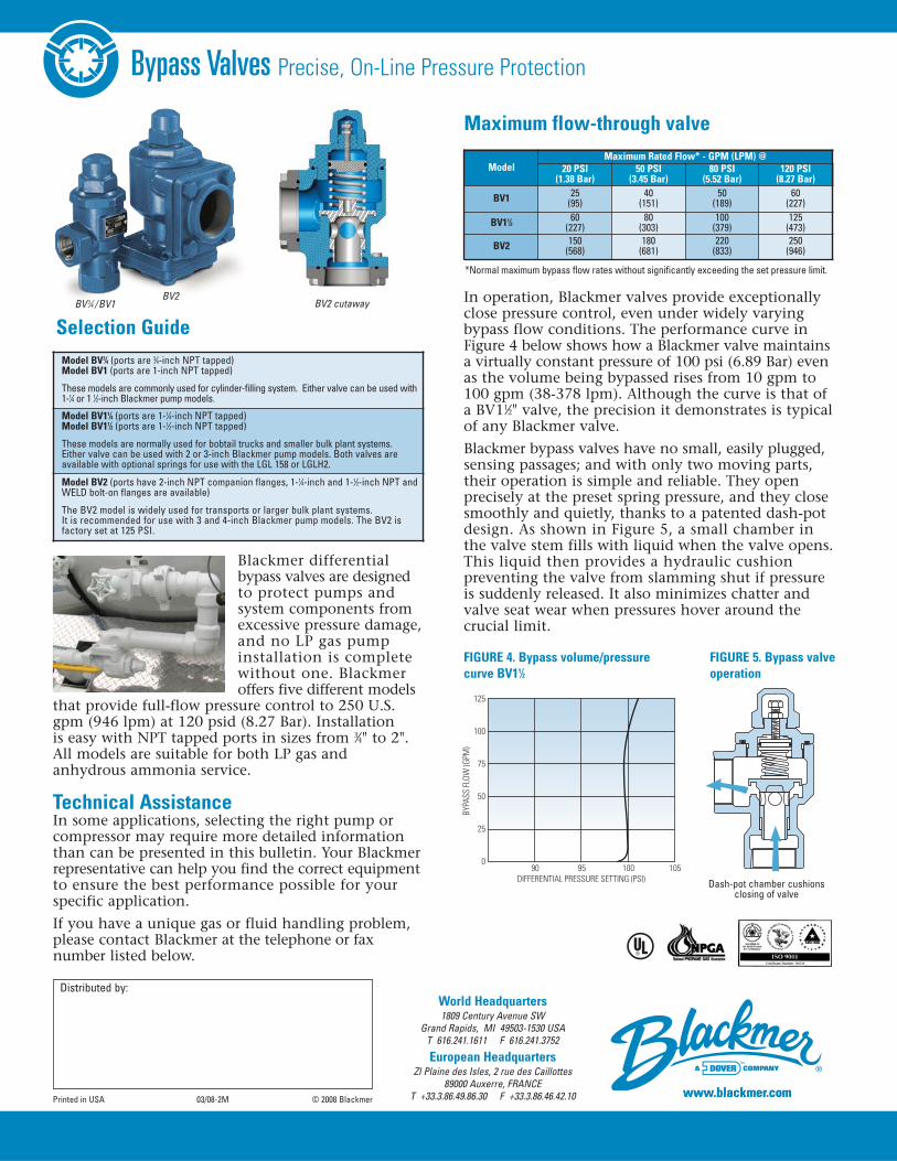
Bypass Valves Precise, On-Line Pressure Protection
Blackmer differentialbypass valves are designedto protect pumps andsystem components fromexcessive pressure damage,and no LP gas pumpinstallation is completewithout one. Blackmeroffers five different models
that provide full-flow pressure control to 250 U.S.gpm (946 lpm) at 120 psid (8.27 Bar). Installationis easy with NPT tapped ports in sizes from 3⁄4" to 2".All models are suitable for both LP gas andanhydrous ammonia service.
Technical AssistanceIn some applications, selecting the right pump orcompressor may require more detailed informationthan can be presented in this bulletin. Your Blackmerrepresentative can help you find the correct equipmentto ensure the best performance possible for yourspecific application.
If you have a unique gas or fluid handling problem,please contact Blackmer at the telephone or faxnumber listed below.
In operation, Blackmer valves provide exceptionallyclose pressure control, even under widely varyingbypass flow conditions. The performance curve inFigure 4 below shows how a Blackmer valve maintainsa virtually constant pressure of 100 psi (6.89 Bar) evenas the volume being bypassed rises from 10 gpm to100 gpm (38-378 lpm). Although the curve is that ofa BV11⁄2" valve, the precision it demonstrates is typicalof any Blackmer valve.
Blackmer bypass valves have no small, easily plugged,sensing passages; and with only two moving parts,their operation is simple and reliable. They openprecisely at the preset spring pressure, and they closesmoothly and quietly, thanks to a patented dash-potdesign. As shown in Figure 5, a small chamber inthe valve stem fills with liquid when the valve opens.This liquid then provides a hydraulic cushionpreventing the valve from slamming shut if pressureis suddenly released. It also minimizes chatter andvalve seat wear when pressures hover around thecrucial limit.
Model BV3⁄4 (ports are 3⁄4-inch NPT tapped)Model BV1 (ports are 1-inch NPT tapped)
These models are commonly used for cylinder-filling system. Either valve can be used with1-1⁄4 or 1 1⁄2-inch Blackmer pump models.
Model BV11⁄4 (ports are 1-1⁄4-inch NPT tapped)Model BV11⁄2 (ports are 1-1⁄2-inch NPT tapped)
These models are normally used for bobtail trucks and smaller bulk plant systems.Either valve can be used with 2 or 3-inch Blackmer pump models. Both valves areavailable with optional springs for use with the LGL 158 or LGLH2.
Model BV2 (ports have 2-inch NPT companion flanges, 1-1⁄4-inch and 1-1⁄2-inch NPT andWELD bolt-on flanges are available)
The BV2 model is widely used for transports or larger bulk plant systems. It is recommended for use with 3 and 4-inch Blackmer pump models. The BV2 isfactory set at 125 PSI.
ModelMaximum Rated Flow* - GPM (LPM) @
20 PSI(1.38 Bar)
50 PSI(3.45 Bar)
80 PSI(5.52 Bar)
120 PSI(8.27 Bar)
BV1 25(95)
40(151)
50(189)
60(227)
BV11⁄2 60(227)
80(303)
100(379)
125(473)
BV2 150(568)
180(681)
220(833)
250(946)
Selection Guide
FIGURE 4. Bypass volume/pressurecurve BV11⁄2
Maximum flow-through valve
FIGURE 5. Bypass valveoperation
*Normal maximum bypass flow rates without significantly exceeding the set pressure limit.