FOR LEGACY XL / 2927 / 2027 TRACTORS - · PDF filesnow cab #1694402 for legacy xl / 2927 /...
15
SNOW CAB #1694402 FOR LEGACY XL / 2927 / 2027 TRACTORS INSTALLATION INSTRUCTIONS - PARTS LIST IMPORTANT READ THIS MANUAL CAREFULLY AND KEEP FOR FUTURE REFERENCE CAUTION ! REMOVE THE VINYL PANELS FOR TRANSPORT IN AN OPEN TRUCK OR TRAILER WARNING ! THIS CAB WILL NOT PROTECT OPERATOR FROM INJURIES CAUSED BY ROLLOVER, COLLISION, OR OTHER ACCIDENTS 11346803 1
-
Upload
hoangthuan -
Category
Documents
-
view
219 -
download
1
Transcript of FOR LEGACY XL / 2927 / 2027 TRACTORS - · PDF filesnow cab #1694402 for legacy xl / 2927 /...

SNOW CAB #1694402 FOR
LEGACY XL / 2927 / 2027 TRACTORS
INSTALLATION INSTRUCTIONS - PARTS LIST
IMPORTANT READ THIS MANUAL CAREFULLY AND KEEP FOR FUTURE REFERENCE
CAUTION ! REMOVE THE VINYL PANELS FOR TRANSPORT IN AN OPEN TRUCK OR TRAILER
WARNING ! THIS CAB WILL NOT PROTECT OPERATOR FROM INJURIES CAUSED BY ROLLOVER,
COLLISION, OR OTHER ACCIDENTS 11346803 1

WARNING
This cab is designed to provide foul weather protection only. It does not provide protection from noise, exhaust fumes, chemicals or injury from collision, or other accidents. 1. Do not operate machine in confined areas without proper ventilation 2. Thoroughly check area of operation before using machine 3. The cab adds height to the machine. Low tree limbs and other overhead structures that did not interfere with the operation of the machine before, may now be obstacles
MAINTENANCE INSTRUCTIONS Periodically check all bolts to see that they are tight. If bolts become loose, failure of cab parts may occur. Door latches and hinges should be lubricated with light machine oil for proper operation.
DO NOT CLEAN THE CLEAR PLASTIC WINDOWS WHEN THE PLASTIC IS DRY.
THE CLEAR PLASTIC WILL SCRATCH.
Avoid contact with plastic windows. Keep plastic windows clean by washing them with clear running water and rubbing with your bare hands, only. The use of a rag, sponge or brush will scratch the plastic. Liquid soap may also be used for window cleaning. During freezing weather, an automotive windshield washer solvent may be used. Use liquid soap and water to clean colored vinyl portions. Scrubbing with a brush or rag is also permitted on the colored vinyl portions
STORAGE INSTRUCTIONS Prior to storage clean the windows and colored vinyl parts with a mild automotive detergent, rinse with clean water and allow to thoroughly dry, Store cab in a clean dry place out of direct sunlight. Avoid folding plastic windows.
READ THIS MANUAL COMPLETELY BEFORE BEGINNING INSTALLATION.
• The right side of the machine is determined from the operators seated position. • Right Hand parts are identified with orange label.
• The words "bolt" will refer to a 1/4”x5/8” bolt and "lock nut"’ will refer to a 1/4” locknut unless
specified otherwise.
• Do not tighten bolts during assembly unless instructed to do so. 2

Carton Contents: Snow Cab #1694402
Key #
Part #
Qty.
Description
1 11347 1 Foot, RH 2 11348 1 Foot, LH 3 11349 1 Front Post, RH 4 11350 1 Front Post, LH 5 11237 1 Front Cross Bar 6 11351 1 Foot Pocket Guard, RH 7 11352 1 Foot Pocket Guard, LH 8 11353 1 Rear Bracket, RH 9 11354 1 Rear Bracket, LH 10 11355 1 Rear Cross Bar 11 11356 1 Rear Post, RH 12 11357 1 Rear Post, LH 13 11234 1 Top Frame 14 11359-B 1 Rear Curtain 15 11360-B 1 Front Panel Vinyl 16 11361-B 1 Door, RH 17 11362 1 Door Bottom, RH 18 11363-B 1 Door, LH 19 11364 1 Door Bottom, LH 20 10000 1 ABS Plastic Top 21 10120 1 Safety Glass Windshield 22 11365 1 Exhaust Deflector 11258 1 Door Hardware Package 11370 1 Rear View Mirror Kit 11371 1 Electric Wiper Kit 11369 1 Hardware Package (contents listed below) 9948 28 1/4”-20 x 5/8” Flange Lock Bolt 908 4 1/4”-20 x 1 ½” Hex Bolt 1514 2 1/4” Flat Washer 9660 4 1/4”-20 Flange Lock Nut 9631 8 1/2”-13 x 1 1/2” Hex Bolt 3317 8 1/2” Split Lock Washer 1657 8 1/2”-13 Hex Nut 11368 4 Rear Bracket Spacer 7628 1 10-24 x 1/2” Screw Optional Accessories Available: # 9855 Flashing Amber Caution Light
CAUTION ! REMOVE THE VINYL PANELS FOR TRANSPORT IN AN OPEN TRUCK OR TRAILER.
3

FIGURE 1 A. Use the carton contents lis
1
t and Figure 1 to identify all the steel parts.
2
34
56
7
8
9
10
11
12
13
4

Step 2; See Figure 2:
Figure 2
Install right & left Foot (1 & 2)) A. Place the right Foot onto the side of the tractor frame and align the holes. B. Insert the 1/2” bolts outwards. Add 1/2” nuts and lock washers. Do not tighten at this time. C. Install the left foot in the same manner. Step 3; See Figure 3: Install Right Front Post (3) (with bent lower end) and a right Foot Pocket Guard (6) Note: Right Foot Pocket Guard has longer bent end than left. A. Insert lower end of the right Front Post into the upper end of the right Foot. Insert a 1/4” x 1 1/2” bolt through the hole in the Foot Pocket Guard. B. Align the holes in the post and foot. Insert the bolt inwards. Add a locknut. Tighten the bolt enough to hold the Foot Pocket Guard in place.
Figure 3
1
3
6
5
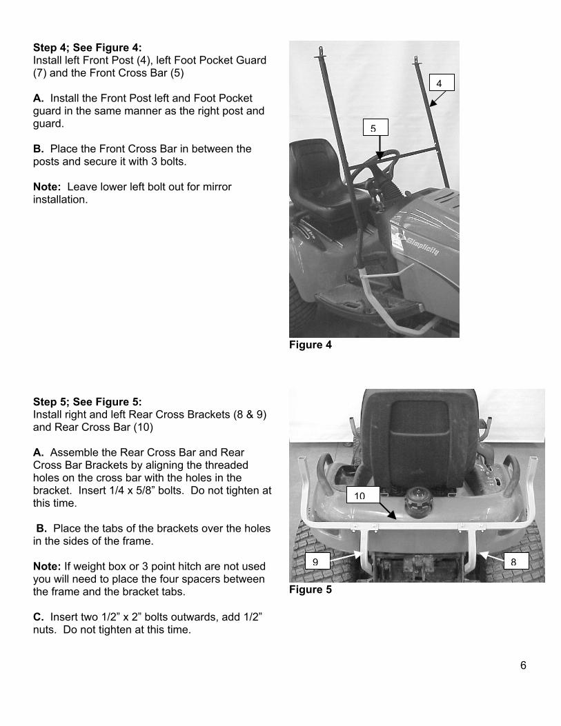
Step 4; See Figure 4:
Install left Front Post (4), left Foot Pocket Guard (7) and the Front Cross Bar (5)
5
4 A. Install the Front Post left and Foot Pocket guard in the same manner as the right post and guard. B. Place the Front Cross Bar in between the posts and secure it with 3 bolts. Note: Leave lower left bolt out for mirror installation. Figure 4
Figure 5
Step 5; See Figure 5: Install right and left Rear Cross Brackets (8 & 9) and Rear Cross Bar (10) A. Assemble the Rear Cross Bar and Rear Cross Bar Brackets by aligning the threaded holes on the cross bar with the holes in the bracket. Insert 1/4 x 5/8” bolts. Do not tighten at this time. 10
B. Place the tabs of the brackets over the holes in the sides of the frame.
89Note: If weight box or 3 point hitch are not used you will need to place the four spacers between the frame and the bracket tabs.
C. Insert two 1/2” x 2” bolts outwards, add 1/2”
nuts. Do not tighten at this time. 6

NOTE: The latch plate on the rear posts should be facing forward with the notch to the outside. Step 6; See Figure 6: Install right & left Rear Posts (11 & 12) A. Insert the right Rear Post into the right end of the Rear Cross Bar. Place a 1/4” flat washer over two 1/4” x 1 1/2” bolts. Insert the bolts outwards. B. Repeat this step on the left side with the left Rear Post. Add lock nuts and tighten. Figure 6 NOTE: The front of the top frame has the threaded holes closest to the corners.
Figure 7
Step 7; See Figure 7: Install the Top Frame (13) A. Place the Top Frame onto the upper ends of the posts. B. Fasten the Top Frame to the posts with three bolts at each connection. Tighten the bolts. C. Tighten all bolts from previous steps at this time.
11
12
13
7

Step 8; See Figure 8:
Install Rear Curtain (14). A. Place the Rear Curtain onto the rear of the frame. Close the snap flaps at the corners. B. Close the snap flaps around the Rear Posts and the ends of the Rear Cross Bar. 14 C. Secure the flap around the Rear Cross Bar. Note: Make sure the pocket is placed so that the fuel filler remains on the outside of the cab.
Figure 8 Step 9; See Figure 9:
Figure 9
Install front Panel Vinyl (15). A. Place the Front Panel Vinyl over the tractor hood and cab frame. Lay the sewn-in rod at the top of the panel over the Front Cross Bar. 15
8

Step 10; See Figure 10: Install Plastic Top (20)
F
A. Place the Plastic Top over the Top Frame. Keep the rod sewn into the Rear Curtain laying over the rear of the frame to hold it in place. Do not insert bolts at this time. Step 11; See Figure 11: Install the right Door (16), left Door (18), right Door Bottom (17) and left Door Bottom (19). A. Follow the instructions in the door latch package to install Hinges, Doors, Door Bottoms and Latches. B. Make sure that the forward edge of the front posts between the arrows is clean. Peel the backing off of the adhesive fastener and secure it to the forward edge of the posts. This will keep the vinyl in place as the windshield is installed. F
20
igure 10
igure 11
9

Step 12; See Figure 12:
Install Windshield (21), Secure Front Panel Vinyl A. Set the Windshield into position on top of the Front Panel Vinyl as it lies over the Front Cross Bar. B. Hold the front of the Plastic Top up and push the Windshield into position on the frame. Lower the top so that it traps the windshield in place.
21
C. Hook the springs at the bottom of the Front Panel Vinyl under the step plates. D. Press the hook and loop fastener on the Front Panel Vinyl and the Doors together.
Figure 12 Step 13; See Figure 13: Secure the Plastic Top (20), Install Windshield
Wiper and Rear View Mirror
Figure 13
A. Insert four bolts inwards through the top and the tabs on the posts. Add locknuts and tighten. Note: Leave front left bolt out for mirror installation. B. Install the Windshield Wiper per the attached instructions. C. Install the Rear View Mirror per the attached instructions.
10

STEP 14; SEE FIGURE 14:
Figure 14
Install Exhaust Deflector (22). 22A. Place the deflector over the exhaust pipe. Turn it up so that it does not interfere with the left front tire when turned to the left with axle pivoted up on the left.
B. Drill a 1/8” hole in the pipe at the location of the hole in the deflector. Use the #10-24 x ½” screw to secure the deflector.
For Replacement Parts Contact:
Original Tractor Cab Co., Inc. P.O. Box 97 6849 W. Front St.
Arlington, IN 46104 Phone 765-663-2214 Fax 765-663-2101
Email [email protected]
Visit us on the web to see our other products. www.originalcab.com
Cabs for Lawn Tractors, Garden Tractors, Compact Tractors, Snow Blowers, Utility Vehicles
Sunshades for Tractors, Mowers, & Utility Vehicles
Storage Covers for Lawn and Garden equipment.
11

LIMITED WARRANTY SNOW REMOVAL EQUIPMENT CABS
COVERED BY WARRANTY
ORIGINAL TRACTOR CAB CO., INC., (the "Company") warrants to the owner that each new product listed below is merchantable and free of defects in workmanship and material. During the warranty period, the dealer from whom the product was bought, or the Company, will provide, free of charge, parts and the shipping costs of parts necessary to correct any defect in workmanship and material.
WARRANTY PERIOD The company products listed below are warranted for the stated period from the date of the original purchase: 1. Cabs for tractors and snow removal equipment 1 Year 2. Company manufactured accessories for above cabs 1 Year 3. Sunshades for lawn and garden tractors 1 Year 4. Repair parts 1 Year
OWNER'S RESPONSIBILITIES The owner of a new Company manufactured product must do the following to qualify for warranty service : 1. Retain the original invoice or other proof of purchase to avoid unnecessary difficulties in determining eligibility for warranty work. 2. Notify the dealer from whom the product was bought, or the company, as soon as possible after discovery of a possible defect, and provide proof of original purchase. To notify the company write to: Original Tractor Cab Co., Inc., P.O. Box 97, Arlington, IN 46104. 3.the owner may , upon notification by the Company, be required to return the defective part, or parts, to the Company for inspection and warranty service.
NOT COVERED BY WARRANTY The following are not covered by this warranty: 1. Transportation charges to and from servicing dealer or the Company; 2. New products which have been subject to misuse, negligence or accident, or have been altered or repaired in a manner not authorized by the company; 3. Windshield wipers, lights, or accessories that are warranted separately by their respective manufacturers, except Company agrees to make available to the owner whatever warranty benefits may be made available to the Company by the manufacturers. All implied warranties, except to the extent prohibited by any applicable law, shall have no greater duration than the warranty period for the applicable product, some states do not allow limitation on how long an implied warranty lasts, so the above limitation may not apply to you. The Companys' liability arising out of warranties representation, instructions, or defects from any abuse, shall be limited exclusively to repair or replacing parts under the condition in the warranty, and in no event will Company be liable for incidental or consequential damages. Some states do not allow the exclusion or limitation of incidental or consequential damages, so the above limitation or exclusion may not apply to you. This warranty gives you specific legal rights, and you may also have rights that vary from state to state.

#11370 Rear View Mirror Kit Left Side Mount
Part # Quantity Description 11134 1 Mirror Head 11366 1 Upper Bracket 11367 1 Lower Bracket
Installation Instructions
Note: Front Panel Vinyl and Plastic top
removed for clarity.
A. Use the bolt and lock washers on the Mirror Head to fasten the Upper and Lower Brackets to the mirror head. Place the lock washers on the outside of the brackets. Do not tighten. B. Insert a bolt through the Upper Mirror Bracket, the Plastic top and then the tab, add a nut. Do not tighten. C. Place the bent end of the Lower Mirror Bracket through the hole in the vinyl. Insert a bolt through the Lower Mirror Bracket, the front cross bar tab and into the post. Tighten all bolts. D. The three screws on the back of the mirror head can be loosened or tightened to set the tension on the mirror pivot. 11370803
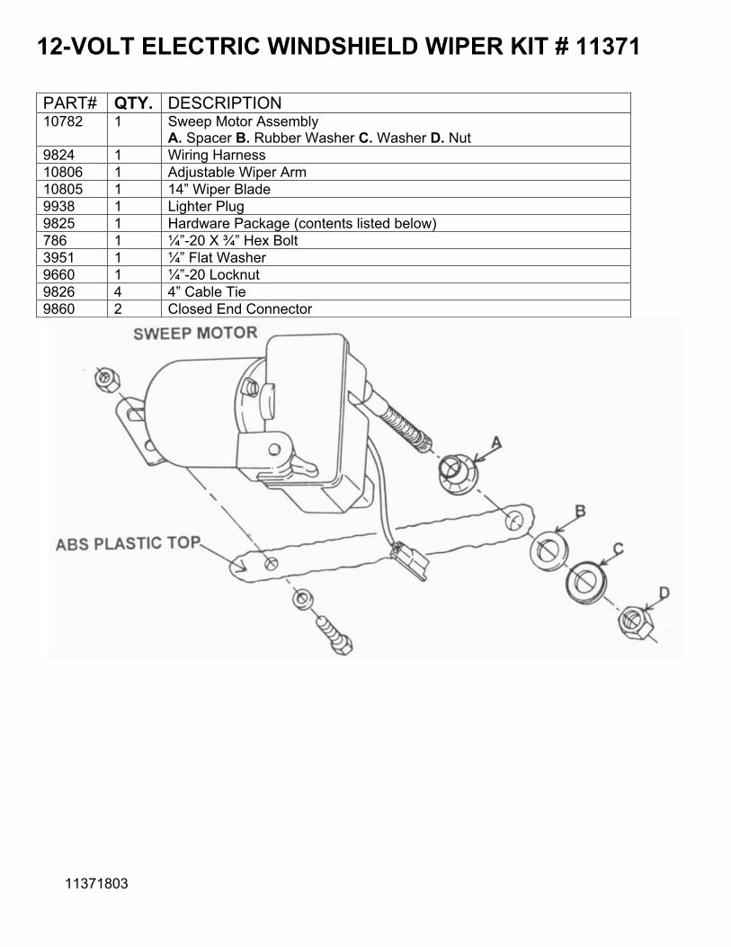
12-VOLT ELECTRIC WINDSHIELD WIPER KIT # 11371 PART# QTY. DESCRIPTION 10782 1 Sweep Motor Assembly
A. Spacer B. Rubber Washer C. Washer D. Nut 9824 1 Wiring Harness 10806 1 Adjustable Wiper Arm 10805 1 14” Wiper Blade 9938 1 Lighter Plug 9825 1 Hardware Package (contents listed below) 786 1 ¼”-20 X ¾” Hex Bolt 3951 1 ¼” Flat Washer 9660 1 ¼”-20 Locknut 9826 4 4” Cable Tie 9860 2 Closed End Connector
11371803

INSTALLATION
1. Remove the nut and washers from the stem.
2. Insert the Sweep Motor shaft into the 5/8” hole.
3. Place the rubber washer, plastic washer and then the nut on the stem.
4. Place a ¼” flat washer on the ¼” x ¾” bolt and insert from the outside through the ¼” hole in
the top and then the flange on the sweep motor. Add a ¼” locknut and tighten both nuts.
5. Plug the wire harness into the wiper motor. Run the wires along the top frame and Secure with the cable ties. Use the flaps on the Rear Curtain to secure the wires to the Rear Post. 6. Trim the wire on the Lighter Plug and harness to correct length.
7. Use the Closed End Connectors to connect the wires.
8. Make sure the motor switch is in the off position and insert the Lighter Plug.
9. Attach the wiper blade to the wiper arm with the screw provided.
10. With the blade all the way to the right press the arm onto the shaft.
11. Lift the small gray lever under the arm to adjust arm length.
12. Turn motor on and check for proper sweep.