For Keenlon Rarduino - robotshop.com · ArduBlock A visual flowchart editor that can generate C...
18
User manual For Keenlon Rarduino Design & Executive Shanghai Keenlon Hi-Tech Co., Ltd. Service [email protected] Website www.keenlon.com
Transcript of For Keenlon Rarduino - robotshop.com · ArduBlock A visual flowchart editor that can generate C...

User manual
For Keenlon Rarduino
Design & Executive Shanghai Keenlon Hi-Tech Co., Ltd.
Service [email protected]
Website www.keenlon.com

Contents
3 Programming software installation guide
5 Programming software user manual
11 Mainboard
11 Mainboard at a glance
12 Mainboard programming examples
12 Anolog input
13 Digital input
14 Digital output
15 PWM output
16 Motor control
17 Compound eyes
18 TFT screen

Programming software installation guide
1. Download and install the latest arduino IDE from arduino official
webside---http://arduino.cc/
2. Enter the installation directory for example
“D:\arduino-1.5.2\hardware\arduino\avr\libraries” ,then put our device and sensor
library into the installation.
3. Open arduino IDE,you can find the library and example.
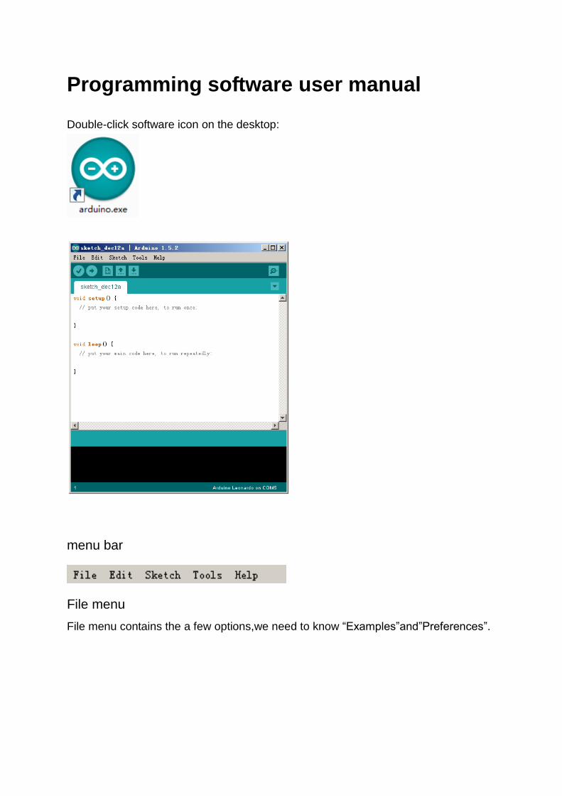
Programming software user manual
Double-click software icon on the desktop:
menu bar
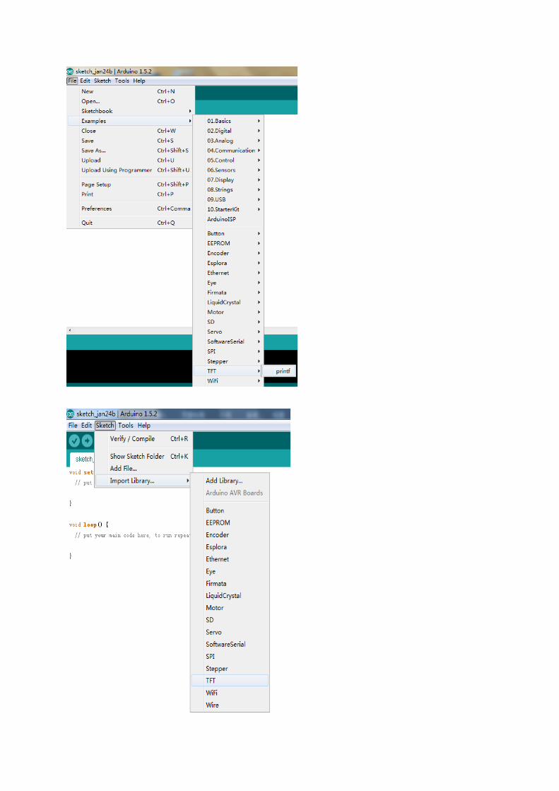
File menu
File menu contains the a few options,we need to know “Examples”and”Preferences”.
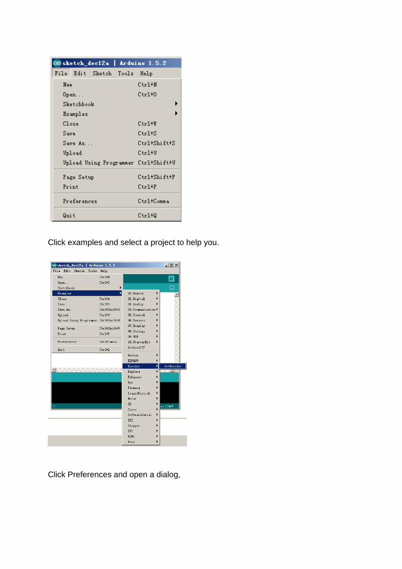
Click examples and select a project to help you.
Click Preferences and open a dialog,
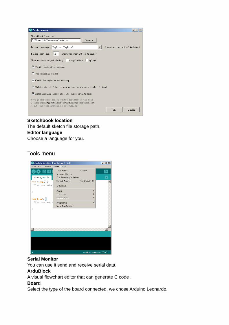
Sketchbook location
The default sketch file storage path.
Editor language
Choose a language for you.
Tools menu
Serial Monitor
You can use it send and receive serial data.
ArduBlock
A visual flowchart editor that can generate C code .
Board
Select the type of the board connected, we chose Arduino Leonardo.

Write a simple program
Create an empty program. Click "File" - "New", the software creates a new window:

The software will automatically generate the following code:
void setup() {
// put your setup code here, to run once:
}
void loop() {
// put your main code here, to run repeatedly:
}
Add the following code
const int analogInPin = A0; /*Define a constant of the analog input port number*/
int sensorValue = 0; /*Define a variable of the analog input value */
void setup() { // put your setup code here, to run once:
Serial.begin(9600); /*Serial port initialization, baud rate 9600*/
}
void loop() { // put your main code here, to run repeatedly:
sensorValue = analogRead(analogInPin);/*Read the analog input value*/
Serial.print("sensor = " );/*Serial port send string*/
Serial.print(sensorValue); /*Serial port send number*/
Serial.print("\n" ); /*Serial port send Character*/
delay(1000); /*The number of milliseconds, delay one second here*/
}
Use usb cable to connect pc and mainboard.
Click the button on the toolbar to compile ,after that click to download
the program.
Click the serial monitor button on the toolbar , or click on "Tools" - "Serial
Monitor" to open the serial port monitor.


Mainboard
Mainboard at a glance
Mainboard combines motor driver and Ardiuno technology.
Power switch
Turn on or off the power.
Power input
6V~12V.
LED
Two LEDs left : power right: breathing light for download.
Start button
Run the program.
Reset button
Reset the Mainboard
USB Mini-B download port
By connecting a USB mini-B cable, you can download your program from PC.
External motor driver interface
Motor port A
Motor port B
Digital port
Analog port
TFT interface
UART port
I2C port
Mainboard programming examples
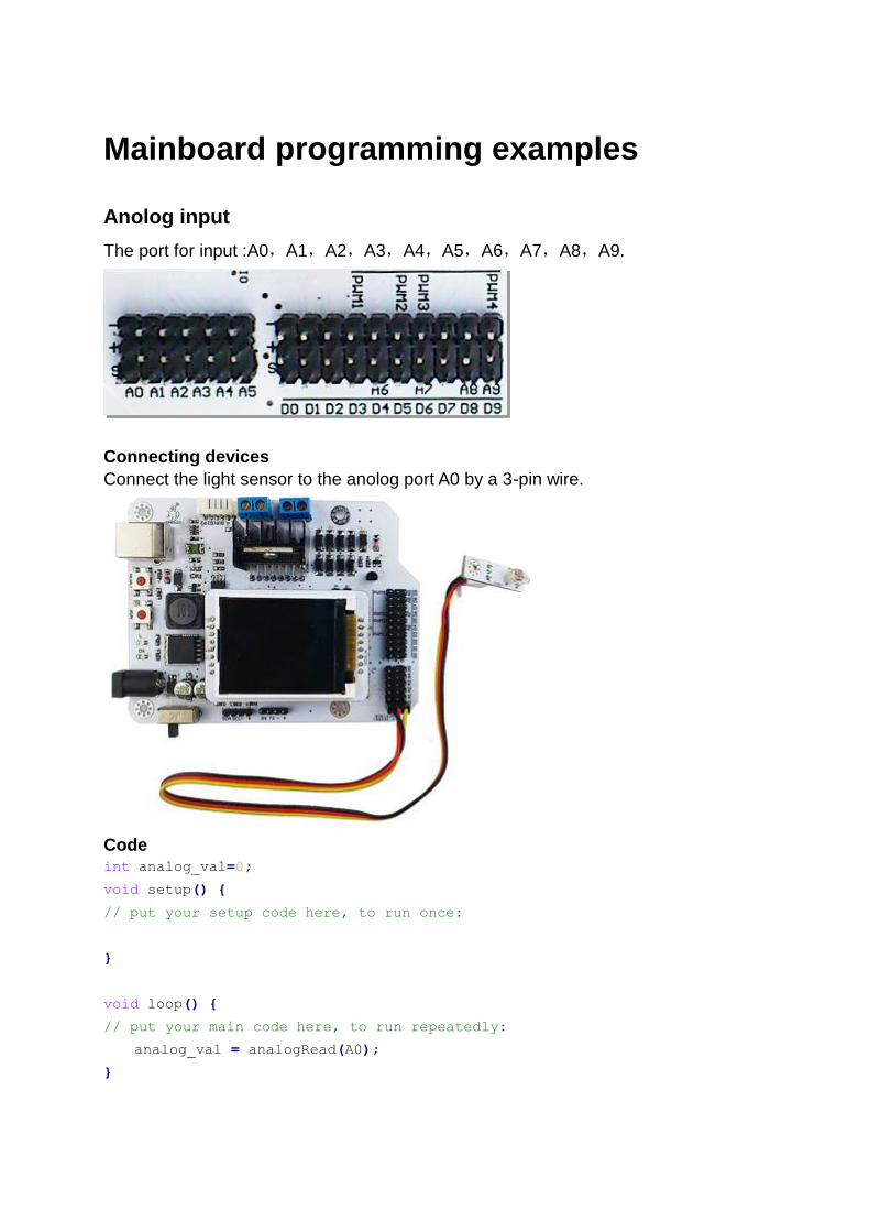
Anolog input
The port for input :A0,A1,A2,A3,A4,A5,A6,A7,A8,A9.
Connecting devices
Connect the light sensor to the anolog port A0 by a 3-pin wire.
Code int analog_val=0;
void setup() {
// put your setup code here, to run once:
}
void loop() {
// put your main code here, to run repeatedly:
analog_val = analogRead(A0);
}

Digital input
The port for input : D0,D1,D2,D3,D4,D5,D6,D7,D8,D9.
Connecting devices
Connect the touch sensor to the digital port D3 by a 3-pin wire.
Code int digital_val=0;
void setup() {
// put your setup code here, to run once:
pinMode(3, INPUT);
}
void loop() {
// put your main code here, to run repeatedly:
digital_val = digitalRead(3);
}
Digital output

The port for output : D0,D1,D2,D3,D4,D5,D6,D7,D8,D9.
We use a RJ11 adapter to connect RJ11 interface sensors.
Connecting devices
Connect the LED board to the digital port D3 by RJ11 cable.
Code void setup() {
pinMode(3, OUTPUT);
}

void loop(){
digitalWrite(3, HIGH);
delay(1000);
digitalWrite(3, LOW);
delay(1000);
}
PWM output
The port for PWM : D3,D5,D6,D9.
Connecting devices
Connect the LED board to the digital port D3 by RJ11 cable.
Code void setup() {
pinMode(3, OUTPUT);
}
void loop() {
for (int i = 0; i < 255; i++) {
analogWrite(3, i);
delay(5);

}
delay(5);
}
Motor control
Connecting devices
Code
#include <Motor.h>
void setup() {
motor.init();
}
void loop() {
motor.run(50,50);
delay(1000);
motor.setMoto(0,0);
delay(1000);
motor.stop();
delay(1000);
}
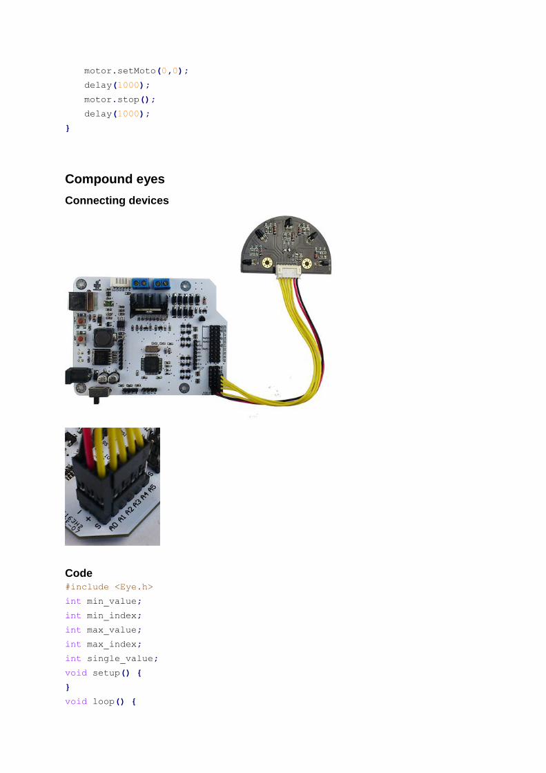
Compound eyes
Connecting devices
Code #include <Eye.h>
int min_value;
int min_index;
int max_value;
int max_index;
int single_value;
void setup() {
}
void loop() {
min_value = eye.minValue();
min_index = eye.minIndex();
max_value = eye.maxValue();
max_index = eye.maxIndex();
single_value = eye.singleValue(0);
}
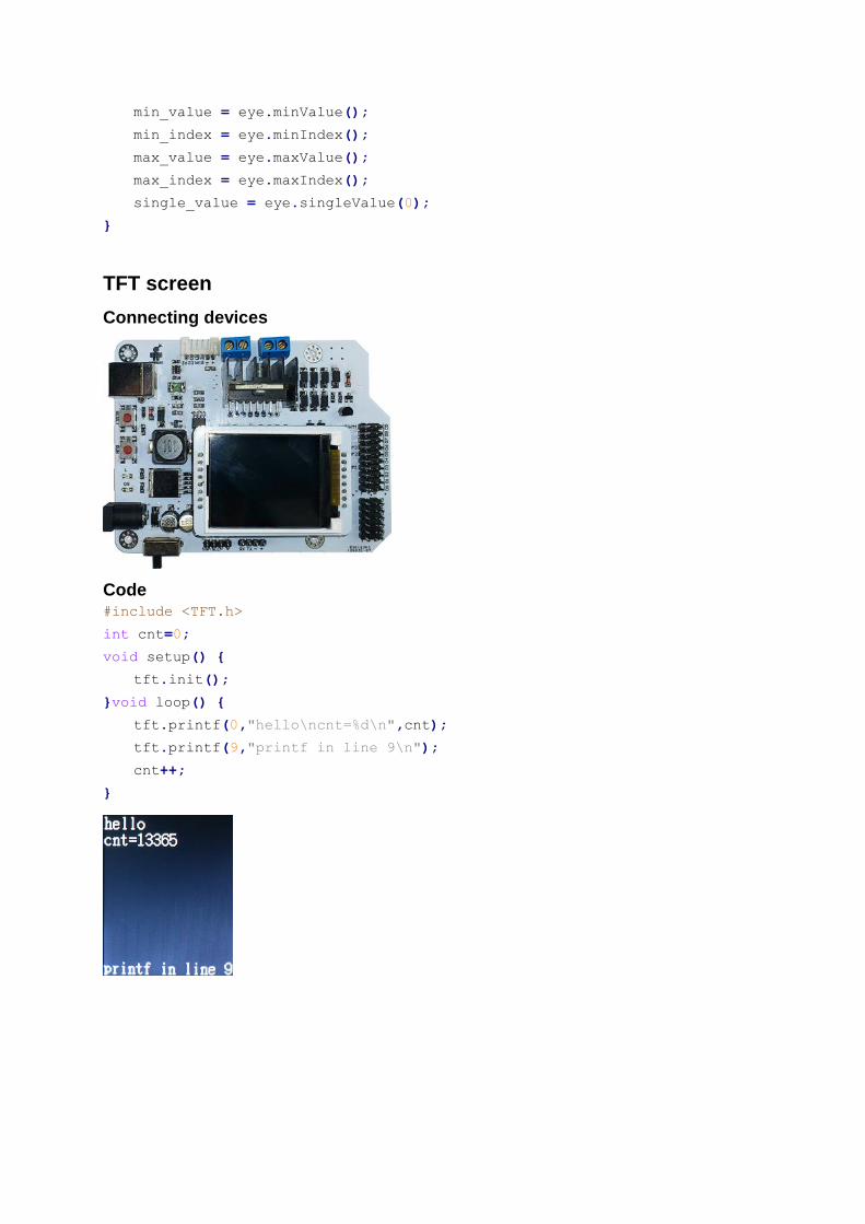
TFT screen
Connecting devices
Code #include <TFT.h>
int cnt=0;
void setup() {
tft.init();
}void loop() {
tft.printf(0,"hello\ncnt=%d\n",cnt);
tft.printf(9,"printf in line 9\n");
cnt++;
}