for GNSS Anti-Spoofing
10
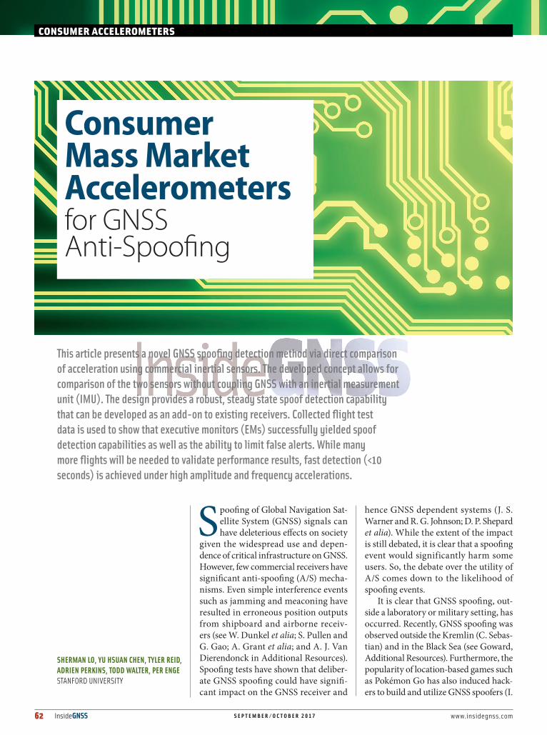
62 InsideGNSS SEPTEMBER/OCTOBER 2017 www.insidegnss.com S poofing of Global Navigation Sat- ellite System (GNSS) signals can have deleterious effects on society given the widespread use and depen- dence of critical infrastructure on GNSS. However, few commercial receivers have significant anti-spoofing (A/S) mecha- nisms. Even simple interference events such as jamming and meaconing have resulted in erroneous position outputs from shipboard and airborne receiv- ers (see W. Dunkel et alia; S. Pullen and G. Gao; A. Grant et alia; and A. J. Van Dierendonck in Additional Resources). Spoofing tests have shown that deliber- ate GNSS spoofing could have signifi- cant impact on the GNSS receiver and hence GNSS dependent systems (J. S. Warner and R. G. Johnson; D. P. Shepard et alia). While the extent of the impact is still debated, it is clear that a spoofing event would significantly harm some users. So, the debate over the utility of A/S comes down to the likelihood of spoofing events. It is clear that GNSS spoofing, out- side a laboratory or military setting, has occurred. Recently, GNSS spoofing was observed outside the Kremlin (C. Sebas- tian) and in the Black Sea (see Goward, Additional Resources). Furthermore, the popularity of location-based games such as Pokémon Go has also induced hack- ers to build and utilize GNSS spoofers (I. This article presents a novel GNSS spoofing detection method via direct comparison of acceleration using commercial inertial sensors. The developed concept allows for comparison of the two sensors without coupling GNSS with an inertial measurement unit (IMU). The design provides a robust, steady state spoof detection capability that can be developed as an add-on to existing receivers. Collected flight test data is used to show that executive monitors (EMs) successfully yielded spoof detection capabilities as well as the ability to limit false alerts. While many more flights will be needed to validate performance results, fast detection (<10 seconds) is achieved under high amplitude and frequency accelerations. CONSUMER ACCELEROMETERS Consumer Mass Market Accelerometers for GNSS Anti-Spoofing SHERMAN LO, YU HSUAN CHEN, TYLER REID, ADRIEN PERKINS, TODD WALTER, PER ENGE STANFORD UNIVERSITY
Transcript of for GNSS Anti-Spoofing
62 InsideGNSS S E P T E M B E R / O C T O B E R 2 0 17 www.insidegnss.com
Spoofing of Global Navigation Sat-ellite System (GNSS) signals can have deleterious effects on society
given the widespread use and depen-dence of critical infrastructure on GNSS. However, few commercial receivers have significant anti-spoofing (A/S) mecha-nisms. Even simple interference events such as jamming and meaconing have resulted in erroneous position outputs from shipboard and airborne receiv-ers (see W. Dunkel et alia; S. Pullen and G. Gao; A. Grant et alia; and A. J. VanDierendonck in Additional Resources).Spoofing tests have shown that deliber-ate GNSS spoofing could have signifi-cant impact on the GNSS receiver and
hence GNSS dependent systems (J. S. Warner and R. G. Johnson; D. P. Shepard et alia). While the extent of the impact is still debated, it is clear that a spoofing event would significantly harm some users. So, the debate over the utility of A/S comes down to the likelihood of spoofing events.
It is clear that GNSS spoofing, out-side a laboratory or military setting, has occurred. Recently, GNSS spoofing was observed outside the Kremlin (C. Sebas-tian) and in the Black Sea (see Goward, Additional Resources). Furthermore, the popularity of location-based games such as Pokémon Go has also induced hack-ers to build and utilize GNSS spoofers (I.
This article presents a novel GNSS spoofing detection method via direct comparison of acceleration using commercial inertial sensors. The developed concept allows for comparison of the two sensors without coupling GNSS with an inertial measurement unit (IMU). The design provides a robust, steady state spoof detection capability that can be developed as an add-on to existing receivers. Collected flight test data is used to show that executive monitors (EMs) successfully yielded spoof detection capabilities as well as the ability to limit false alerts. While many more flights will be needed to validate performance results, fast detection (<10 seconds) is achieved under high amplitude and frequency accelerations.
CONSUMER ACCELEROMETERS
Consumer Mass Market Accelerometers for GNSS Anti-Spoofing
SHERMAN LO, YU HSUAN CHEN, TYLER REID, ADRIEN PERKINS, TODD WALTER, PER ENGESTANFORD UNIVERSITY

www.insidegnss.com S E P T E M B E R / O C T O B E R 2 0 17 InsideGNSS 63
Birnbaum). While the spoofer in Birn-baum uses an expensive GNSS signal generator, other professional security groups have put together GNSS spoofers using low cost software defined radios (SDRs), open source software, and some basic GNSS know-how (see L. Huang and Q. Yang). GNSS spoofing capa-bilities are no longer solely the realm of navigation experts. As time goes by, spoofing capabilities will get better and costs will only decrease.
There are many motivations to spoof. Ordinary citizens may spoof to aid their gaming, to protect their privacy, or to subvert location based charges (e.g., road tolling) or restrictions. A quick search on the Google Play store shows mul-tiple pages of “Fake GPS” applications. The first application, “Fake GPS Loca-tion Spoofer Free,” alone has more than 60,000 reviews as of May 2017. This indi-cates that many people took the time to not only download and use the app but also to comment on its benefits! There is substantial and growing public interest in spoofing location. Coupling these two factors — the availability of GNSS spoof-ing equipment or know-how and public interest in spoofing — means we should expect more spoofing incidents in the future. And while critical infrastructure may not be the target for most spoofers, it may fall victim as collateral damage.
We developed and examined a GNSS spoofing detection method via direct comparison of acceleration using com-mercial inertial sensors. The developed concept allows for comparison of the two sensors without coupling GNSS with an inertial measurement unit (IMU). The design allows for a robust, steady state spoof detection capability that can be developed as an add-on to existing receivers. This article focuses on our preliminary development and dem-onstration of the concept for aviation.
Background: Prior Art & Developed Technique Prior Art and GoalsDespite not being a current commercial concern, there is significant literature on GNSS spoofing detection (see Addi-
tional Resources). Various researchers have proposed and developed numer-ous anti-spoofing techniques. Antenna-based techniques use signal properties such as direction of arrival and polariza-tion to detect the presence of spoofing. Internal receiver metrics can be exam-ined for signatures found in spoofing attacks. This includes changes in auto-matic gain control (AGC) and signal power. The network method checks the received signal against known trusted signals. Redundancy techniques check GNSS measurements against redundant internal or external measures.
While there are many A/S tech-niques, there is no panacea for spoof-ing. There is currently no one technique that ideally satisfies all needs. There will likely need to be different solutions for different users, applications, and requirements. As each technique is likely only good against a subset of threats, the overall solution may actually employ several, complimentary techniques to cover all desired threats. Regardless, the techniques employed should have certain characteristics. First, they need to be robust meaning that they catch the threats that they were designed for while having very low false alert rates. Second, they need to be reasonable to implement. This means that they do not significantly change existing receiver designs or add to their cost. A/S needs to be effective but also transparent to the user. It can-not inconvenience users through false alerts or additional, costly complexity. This motivates our investigation of the use of simple inertial-based techniques.
Use of inertial sensors to comple-ment and cross check GNSS is not new. Traditional aviation GNSS/iner-tial cross-checking algorithms for fault detection have previously been adapted to spoof detection (Y. Liu et alia). Tanil et alia investigated the use of inertials with Kalman filtering to perform spoof-ing detection in the position domain. These techniques, which require com-parisons in the pseudorange or posi-tion domain, essentially require GNSS to regularly calibrate IMU results. The deep intertwining of GNSS information
to transform IMU results to the position domain limit the trustworthiness of the comparison over time. A spoofer may induce a small GNSS error that causes a bias error in the calibration of the accel-eration that can then be slowly exploited. Hence, these spoofing detection meth-ods are considered transient detectors as they only have a limited detection win-dow in which the IMU-derived positions can be considered uncontaminated by GNSS spoof induced errors.
Developed TechniqueOvercoming the limited spoof detection window means not deeply intertwining GNSS with the IMU-derived results. Position domain comparison requires regular calibration of the MEMS acceler-ometer and gyroscope measurements by the GNSS and could cause GNSS spoof induced errors to affect IMU results in a manner that cannot be unraveled. Instead we compare the fundamental IMU outputs of acceleration and rota-tion rate by aligning GNSS and IMU measurement axes. This alignment is accomplished using GNSS information to approximate attitude. For the study, we compared acceleration as measured by the GNSS and IMU and developed test statistics to help decide if spoofing is present. These tests will have to account not just for errors due to the sensors but also for those due to misalignment of the GNSS and IMU coordinate frames. The benefit of the technique developed is that in uncoupling GNSS outputs from the IMU, we provide an unlimited detec-tion window and steady state detection. It also allows the technique to be imple-mented as an overlay so that it can be an add-on to an existing receiver.
Any spoofing attack without a good estimate of the vehicle acceleration should be detectable. Even a spoofer that can measure the acceleration remotely or relay a measurement of accelera-tion from an onboard device may be detectable. This is because the spoofer will incur errors and delays that may be detected provided there are high frequency dynamics. However, there are threats that the technique cannot
64 InsideGNSS S E P T E M B E R / O C T O B E R 2 0 17 www.insidegnss.com
catch. An attacker with accurate and near real-time knowledge of accelera-tion can slowly drift the measured posi-tion from truth as long as they keep the acceleration error within the allowable detection tolerance. Physical security or complimentary detection techniques may handle these threats.
To be ef fective, the technique requires a high frequency component of acceleration and predictable attitude. The former represents in cryptographic terms, a one-time pad that a spoofer cannot guess a priori. In flight, there can be many sources of unpredictable accel-eration — wind, pilot input to thrust, lowering of the landing gear, etc. Oth-ers have considered these items for their ability to provide motion that is difficult for a spoofer to predict (C. Tanil et alia (2015a, 2015b)). Because GNSS alone is used to derive attitude, stable or predict-able attitude is desired. Single antenna GNSS measurements cannot estimate some attitude parameters such as roll angle without additional information. Without a reasonable sense of the true attitude, the reference frames between the IMU and GNSS may not be well-aligned and a comparison between IMU and GNSS accelerations cannot be made. While the requirement seems demand-ing, commercial f lights desire stable attitude, especially on approach. This makes sense as the aircraft should be reasonably steady for landing. It should not have much roll and the pitch angle should be small as the aircraft tries to maintain a small, constant glide slope (approximately three degrees). Another
time where aircraft attitude is reasonably stable is during cruise, i.e., the majority of any flight. Having established a gen-erally stable attitude over the course of a given f light, we now focus on final approach, as it is the most critical phase of flight.
Critical to the utility of the method-ology are two key questions. First, are there adequate motions available for spoof detection using a low cost INS? The motion must be semi-random and significant relative to the capability of the sensors and their errors. This will be examined using flight test data. It must be significant enough to rise above the errors and biases induced by our meth-odology. The second question is whether we can develop a robust, steady-state test metric for spoof detection given that information.
Data Collection & TestingWhile theoretically acceleration from GNSS acceleration and microelectro-mechanical systems (MEMS) inertials should be suitable for aviation and other transportation, real world errors and biases may result in different per-formance. We conducted a flight test to gather data to validate our theoretical conclusions and examine flight distur-bances.
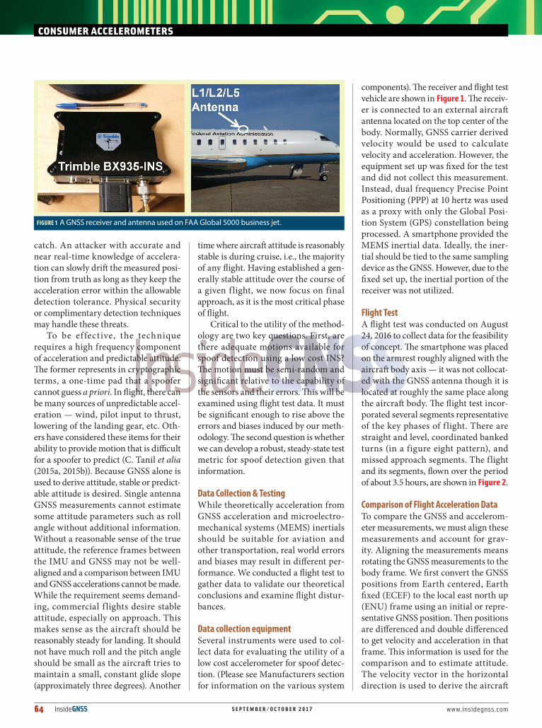
Data collection equipmentSeveral instruments were used to col-lect data for evaluating the utility of a low cost accelerometer for spoof detec-tion. (Please see Manufacturers section for information on the various system
components). The receiver and flight test vehicle are shown in Figure 1. The receiv-er is connected to an external aircraft antenna located on the top center of the body. Normally, GNSS carrier derived velocity would be used to calculate velocity and acceleration. However, the equipment set up was fixed for the test and did not collect this measurement. Instead, dual frequency Precise Point Positioning (PPP) at 10 hertz was used as a proxy with only the Global Posi-tion System (GPS) constellation being processed. A smartphone provided the MEMS inertial data. Ideally, the iner-tial should be tied to the same sampling device as the GNSS. However, due to the fixed set up, the inertial portion of the receiver was not utilized.
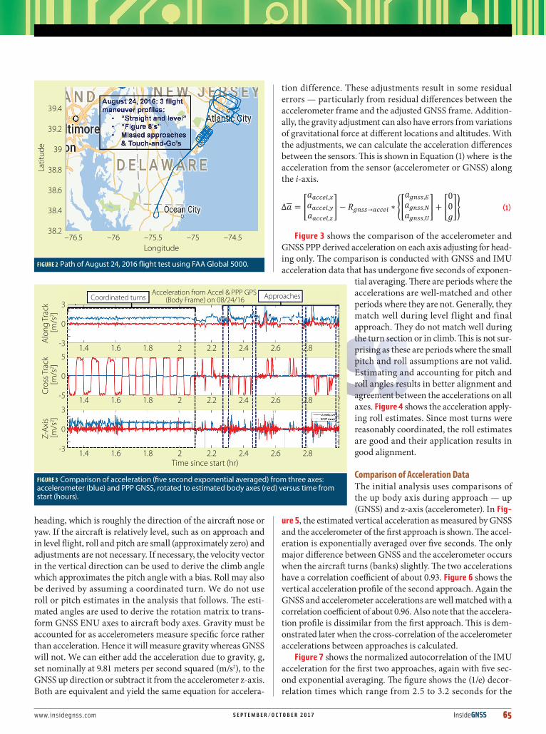
Flight TestA flight test was conducted on August 24, 2016 to collect data for the feasibility of concept. The smartphone was placed on the armrest roughly aligned with the aircraft body axis — it was not collocat-ed with the GNSS antenna though it is located at roughly the same place along the aircraft body. The flight test incor-porated several segments representative of the key phases of f light. There are straight and level, coordinated banked turns (in a figure eight pattern), and missed approach segments. The flight and its segments, flown over the period of about 3.5 hours, are shown in Figure 2.
Comparison of Flight Acceleration DataTo compare the GNSS and accelerom-eter measurements, we must align these measurements and account for grav-ity. Aligning the measurements means rotating the GNSS measurements to the body frame. We first convert the GNSS positions from Earth centered, Earth fixed (ECEF) to the local east north up (ENU) frame using an initial or repre-sentative GNSS position. Then positions are differenced and double differenced to get velocity and acceleration in that frame. This information is used for the comparison and to estimate attitude. The velocity vector in the horizontal direction is used to derive the aircraft
CONSUMER ACCELEROMETERS
FIGURE 1 A GNSS receiver and antenna used on FAA Global 5000 business jet.
www.insidegnss.com S E P T E M B E R / O C T O B E R 2 0 17 InsideGNSS 65
heading, which is roughly the direction of the aircraft nose or yaw. If the aircraft is relatively level, such as on approach and in level flight, roll and pitch are small (approximately zero) and adjustments are not necessary. If necessary, the velocity vector in the vertical direction can be used to derive the climb angle which approximates the pitch angle with a bias. Roll may also be derived by assuming a coordinated turn. We do not use roll or pitch estimates in the analysis that follows. The esti-mated angles are used to derive the rotation matrix to trans-form GNSS ENU axes to aircraft body axes. Gravity must be accounted for as accelerometers measure specific force rather than acceleration. Hence it will measure gravity whereas GNSS will not. We can either add the acceleration due to gravity, g, set nominally at 9.81 meters per second squared (m/s2), to the GNSS up direction or subtract it from the accelerometer z-axis. Both are equivalent and yield the same equation for accelera-
tion difference. These adjustments result in some residual errors — particularly from residual differences between the accelerometer frame and the adjusted GNSS frame. Addition-ally, the gravity adjustment can also have errors from variations of gravitational force at different locations and altitudes. With the adjustments, we can calculate the acceleration differences between the sensors. This is shown in Equation (1) where is the acceleration from the sensor (accelerometer or GNSS) along the i-axis.
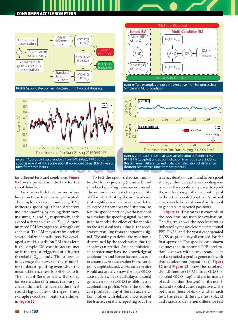
Figure 3 shows the comparison of the accelerometer and GNSS PPP derived acceleration on each axis adjusting for head-ing only. The comparison is conducted with GNSS and IMU acceleration data that has undergone five seconds of exponen-
tial averaging. There are periods where the accelerations are well-matched and other periods where they are not. Generally, they match well during level f light and final approach. They do not match well during the turn section or in climb. This is not sur-prising as these are periods where the small pitch and roll assumptions are not valid. Estimating and accounting for pitch and roll angles results in better alignment and agreement between the accelerations on all axes. Figure 4 shows the acceleration apply-ing roll estimates. Since most turns were reasonably coordinated, the roll estimates are good and their application results in good alignment.
Comparison of Acceleration DataThe initial analysis uses comparisons of the up body axis during approach — up (GNSS) and z-axis (accelerometer). In Fig-
ure 5, the estimated vertical acceleration as measured by GNSS and the accelerometer of the first approach is shown. The accel-eration is exponentially averaged over five seconds. The only major difference between GNSS and the accelerometer occurs when the aircraft turns (banks) slightly. The two accelerations have a correlation coefficient of about 0.93. Figure 6 shows the vertical acceleration profile of the second approach. Again the GNSS and accelerometer accelerations are well matched with a correlation coefficient of about 0.96. Also note that the accelera-tion profile is dissimilar from the first approach. This is dem-onstrated later when the cross-correlation of the accelerometer accelerations between approaches is calculated.
Figure 7 shows the normalized autocorrelation of the IMU acceleration for the first two approaches, again with five sec-ond exponential averaging. The figure shows the (1/e) decor-relation times which range from 2.5 to 3.2 seconds for the
FIGURE 2 Path of August 24, 2016 flight test using FAA Global 5000.
Longitude
Latit
ude
–76.5 –76 –75.5 –75 –74.5
39.4
39.2
39
38.8
38.6
38.4
38.2
FIGURE 3 Comparison of acceleration (five second exponential averaged) from three axes: accelerometer (blue) and PPP GNSS, rotated to estimated body axes (red) versus time from start (hours).
Time since start (hr)
Coordinated turnsAcceleration from Accel & PPP GPS
(Body Frame) on 08/24/16 Approaches
Alon
g Tr
ack
[m/s
2 ]
1.4 1.6 1.8 2 2.2 2.4 2.6 2.8
3
0
-3
Cros
s Tra
ck [m
/s2 ]
1.4 1.6 1.8 2 2.2 2.4 2.6 2.8
5
0
-5
Z-Ax
is [m
/s2 ]
1.4 1.6 1.8 2 2.2 2.4 2.6 2.8
3
0
-3

66 InsideGNSS S E P T E M B E R / O C T O B E R 2 0 17 www.insidegnss.com
CONSUMER ACCELEROMETERS
approaches. Figure 8 shows the cross-correlation of the second approach with the first and third approaches normal-ized by the maximum autocorrelation of the second approach. The maximum normalized cross-correlation value over all approaches is about 0.55. The results indicate a fast decorrelation period and no significant cross-correlation between approaches. These results affirmatively answer the first question: Aircraft accel-eration measured by low cost accelerom-eter can provide meaningful compari-son with GNSS.
We measured the noise on acceler-ometer and GNSS acceleration using static measurements of vertical accel-eration. Without averaging, the accel-erometer showed a mean (µ) and stan-dard deviation (σ) of -0.03 and 0.027 m/s2, respectively, and the PPP GNSS acceleration was zero mean with a stan-dard deviation of 1.198 m/s2. These sta-tistics are used as the basis of our model bounding variance for the statistical spoof detection tests. With five sec-ond exponential averaging, the z-axis accelerometer has a mean of –0.03 m/s2 and standard deviation of 0.003 m/s2. Similarly, PPP up acceleration was zero mean with 0.028 m/s2 standard deviation.
Analysis of Detection and False AlertsThe previous section demonstrated two important qualities. First, low cost accelerometers, not coupled to GNSS, are accurate enough to pro-vide corroborative information to the GNSS-derived movement for aircraft approach. Second, aircraft approaches present useful acceleration signatures that can be used like a cryptographic one-time pad to foil spoofing. The next step is to develop a test for spoofing that can provide robust detection with low probability of false alert. Basic, proof-of-concept monitors were developed using just the accelerometer z-axis and standard statistical testing to demon-strate feasibility. The acceleration com-parison suggests that using the z-axis on the accelerometer provides the best information. In future development,
FIGURE 4 Comparison of acceleration (five second exponential averaged) from three axes: ac-celerometer (blue) and PPP GNSS, rotated to estimated body axes (red) with roll estimation and compensation versus time from start (hours).
Time since start (hr)
Acceleration from Accel & PPP GPS (Body Frame, Roll) on 08/24/16Al
ong
Trac
k [m
/s2 ]
1 1.5 2 2.5 3
1 1.5 2 2.5 3
1 1.5 2 2.5 3
3
0
-3
Cros
s Tra
ck
[m/s
2 ]
5
0
-5
Z-Ax
is [m
/s2 ] 3
0
-3
FIGURE 5 Acceleration (five second exponential averaged) from accelerometer z-axis (body up) (blue) and PPP GNSS, up axis (red) for Approach 1 versus time from start (hours).
Time since start (hr)
Z Acceleration (no pitch corr) from Accel & PPP GPS on 08/24/16
Z-Ac
cele
ratio
n [m
/s2 ]
2.25 2.26 2.27 2.28 2.29
1
0.8
0.6
0.4
0.2
0
-0.2
-0.4
-0.6
-0.8
-1
FIGURE 6 Acceleration (five second exponential averaged) from accelerometer z-axis (body up) (blue) and PPP GNSS, up axis (red) for Approach 2 versus time from start (hours).
Time since start (hr)
Z Acceleration (no pitch corr) from Accel & PPP GPS on 08/24/16
Z-Ac
cele
ratio
n [m
/s2 ]
2.505 2.51 2.515 2.52 2.525
1
0.8
0.6
0.4
0.2
0
-0.2
-0.4
-0.6
-0.8
-1

www.insidegnss.com S E P T E M B E R / O C T O B E R 2 0 17 InsideGNSS 67
other axes and/or sensors may be used either independently or in combination.
Two test statistics are examined and standard hypothesis tests are used to develop monitors based on each test statistic. The first statistic uses the difference in acceleration as mea-sured by GNSS and accelerometer. A spoofed GNSS should experience different accelerations than those measured by the accelerometer. The second statistic examines the standard deviation of the acceleration difference (σΔa). The σΔa should be larger than the nominal value when the accelerations between the two sensors are not well matched. The second test is less sensitive to a relatively constant bias, such as those resulting from axis misalignment.
The first test statistic, z (mean difference), is shown in Equa-tion (2). It examines the mean difference of acceleration (ȳ) normalized by the model standard deviation, σ. It also accounts for the effect of the maximum nominal bias b. The max func-tion used to incorporate the bias since its sign is not known. The statistic should be bounded by a standard normal distri-bution provided the model standard deviation and bias are representative. Hence, our threshold test is to flag if z > zthres. For a 10-9 probability of false alert (Pfa), zthres is 6.1. The sec-ond test statistic, χ2, is shown in Equation (3) with n being the number of samples examined, and s2 and σ2 being the sample and model variances, respectively. For the initial analysis, n = 8 samples are used to generate the sample variance. The sta-
tistic is (central) χ2 distributed with (n-1) degrees of freedom (dof). Similarly, our threshold test is to flag when with
being 55.87 for 10-9 and dof equal to 7 (since n = 8). Both statistical tests depend on the model standard deviation, σ, of the acceleration difference. As such, incorrect modeling affects the monitor performance. If σ is too large, then there will be a larger missed detection rate than modeled. Given the steady state nature of the developed spoof detector, this may be accept-able as there are many chances to catch the spoofer. If σ is too small, the false alert rate will be higher than expected. This is the worse outcome of the two possibilities as it may lead users to distrust the system. So it is better to err on the side of slightly too large. For our testing, the exponential average values are used for the test statistics. The model standard deviation, σ, used is 0.06 m/s2 which is twice the root sum squared (rss) of the standard deviation of the accelerometer and GNSS accel-eration, as found in the static tests. As the exponential average is used, the static exponential average standard deviations are used. This is shown in Equation (4). A test bias, b, of 0.03 m/s2
and n = 8 samples are used.
The statistical tests provide the basic building blocks for the spoof detection monitor. There are several considerations that the monitor must address. One important consideration is minimizing false alerts. Each test may get flagged in non-spoofing situations if our assump-tions are not well met. For example, un-modeled attitude can cause large differ-ences in the z-axis accelerometer and up GNSS acceleration. Another consideration is that the tests will not flag during every instant where there is spoofing. For exam-ple, the first test will not flag if the spoofed acceleration happens to be within the allowable error tolerance of the true accel-eration. This can happen purely by chance or if the acceleration does not vary much and so is easy to anticipate. The monitor should be designed to be robust to these issues. A moving observation window is used primarily to reduce false alerts. Initially a five second window is chosen since this is larger than the decorrelation time. Within the window, each test flag must exceed specified thresholds a cer-tain number of times before the monitor issues an alert. The thresholds may differ
FIGURE 7 Autocorrelation of Approach 1 and Approach 2 up acceleration.
Time (sec)
Auto
corre
latio
n μ
= –
0.03
6, σ
= 0
.249
AutoCorr, τ = 3.1 sec, start time = 2.24
–200 –100 0 100 200
1
0.8
0.6
0.4
0.2
0
–0.2
–0.4
Time (sec)
Auto
corre
latio
n
AutoCorr, τ = 2.5 sec, start time = 2.5
–100 0 100
1
0.8
0.6
0.4
0.2
0
–0.2
–0.4
FIGURE 8 Cross-correlation of Approach 2 with Approach 1 and Approach 3 up acceleration.
Time (sec)
Xcor
r (tim
es =
2.5
, 2.2
4)
XCorr, τ = –29.35 sec
–100 0 100 200
0.4
0.2
0
–0.2
–0.4
–0.6
Time (sec)
Xcor
r (tim
es =
2.5
, 2.7
8)
XCorr, τ = –84.1 sec
–100 0 100
0.2
0.1
0
–0.1
–0.2
68 InsideGNSS S E P T E M B E R / O C T O B E R 2 0 17 www.insidegnss.com
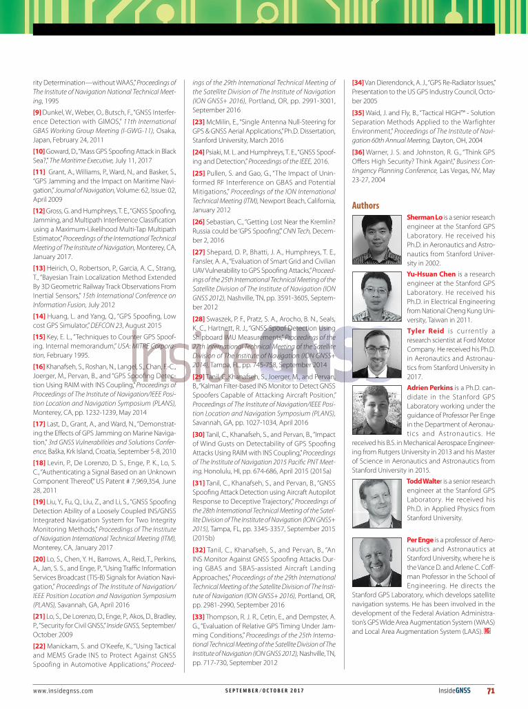
for different tests and conditions. Figure 9 shows a general architecture for the spoof detection.
Two overall detection monitors based on these tests are implemented. The simple executive monitoring (EM) indicates spoofing if both detectors indicate spoofing by having their mov-ing sums, Σ1 and Σ2, respectively, each exceed a threshold value, Σthres. A more nuanced EM leverages the strengths of each test. The EM may alert for each of several different conditions. We devel-oped a multi-condition EM that alerts if the simple EM conditions are met or if the χ2 test triggered at a higher threshold, Σthres,2 only. This allows us to leverage the power of the χ2 moni-tor to detect spoofing even when the mean difference test is oblivious to it. The mean difference test will not flag for acceleration differences that vary by a small shift in time, whereas the χ2 test could f lag variation changes. These example executive monitors are shown in Figure 10.
To test the spoof detection moni-tor, both no spoofing (nominal) and simulated spoofing cases are examined. The nominal case tests the probability of false alert. Testing the nominal case is straightforward and is done with the collected data without modification. To test the spoof detection, we do not need to simulate the spoofing signal. We only need to model the effect of the spoofer on the statistical tests – that is, the accel-eration resulting from the spoofing sig-nal. The ability to defeat the monitor is determined by the acceleration that the spoofer can predict. An unsophisticat-ed spoofer may have no knowledge of acceleration and hence its best guess is to assume zero acceleration in the verti-cal. A sophisticated, worst-case spoofer would accurately know the true GNSS acceleration with a small delay and could generate a spoofed GNSS exhibiting any acceleration profile. While the spoofer can produce many different accelera-tion profiles with delayed knowledge of the true acceleration, repeating back the
true acceleration was found to be a good strategy. This is an extreme spoofing sce-nario as the spoofer only cares to spoof the acceleration profile without regard to the actual spoofed position. An actual attack would be constrained by the need to generate its spoofed positions.
Figure 11 illustrates an example of the accelerations used for evaluation. The figure shows the acceleration as indicated by the accelerometer, nominal PPP GNSS, and the worst case spoofed GNSS as previously discussed for the first approach. The spoofed case shown assumes that the nominal PPP accelera-tion is known with a two second delay and a spoofed signal is generated with that acceleration (repeat back). Figure 12 and Figure 13 show the accelera-tion difference (IMU minus GNSS or spoofed GNSS, top) and performance of each monitor (bottom) for the nomi-nal and spoofed cases, respectively. The bottom of those plots show when each test, the mean difference test (black) and standard deviation difference test
CONSUMER ACCELEROMETERS
FIGURE 9 Spoof detection architecture using two test statistics.
Yes
No
Accelerationdifference (y)
Meandifference
test
Movingsum (Σ1)
Executivemonitor
Movingsum (Σ2)
Standarddeviation
(Χ2) test
SpoofDetected
No SpoofIndicated
–
GPS verticalacceleration
Accel. verticalgravity corrected
acceleration
FIGURE 10 Two examples of possible executive monitor processing: Simple and Multi-condition.
Mean di�(Σ1) > Σthres
Std di� (Χ2)(Σ2) > Σthres
YES: Spoof Detected
NO: No Spoof Indicated
Simple EM
AND
(Σ1) > Σthres
(Σ2) > Σthres
(Σ2) > Σthres,2 only
Multi-Condition EM
AND OR
FIGURE 11 Approach 1 accelerations from IMU (blue), PPP (red), and spoofer repeat of PPP acceleration (two second delay) (black) versus time from start (hours).
Time since start (hr); Start 24-Aug-2016 06:51:47
Acce
l [m
/s2 ]
2.25 2.26 2.27 2.28 2.29
0.8
0.6
0.4
0.2
0
-0.2
-0.4
-0.6
-0.8
FIGURE 12 Approach 1 nominal case, acceleration difference (IMU – PPP GPS) (top plot) and spoof indication from each test statistics (black = mean difference, red = standard deviation of difference) (bottom plot) versus time from start (hours).
Time since start (hr); Start 24-Aug-2016 06:51:47
GPS
-IMU
Ac
cel [
m/s
2 ]
2.25 2.26 2.27 2.28 2.29
2.25 2.26 2.27 2.28 2.29
1
0
-1
Test
Fla
gIn
dica
ted 1.5
1
0.5
0

www.insidegnss.com S E P T E M B E R / O C T O B E R 2 0 17 InsideGNSS 69
(red), was triggered over the course of the approach. A zero value indicates no spoofing while a non-zero value (1.5 and 1 for acceleration difference and stan-dard deviation, respectively) indicates a flag by the specified test. In the nominal case, the standard deviation test f lags only once while the mean difference test did not flag. In the spoofing case, each test flags many times on the approach though there are some quiet periods where neither tests flag. Figure 14 shows the number of times each test, the mean difference test (black), standard devia-tion difference test (red), and the sum for both tests (blue), flags over a moving five second (50 sample) window. The top shows the nominal case while the bot-tom shows the spoofed case. As desired, there is not much happening in the nominal case. Examining the spoofing case, there are many intervals where the tests flag 20-40 times each or 40-80%. However, there are other intervals where there are no flags. Comparing the time periods where there are spoofing flags
to the accelerations shown in Figure 11 suggests that the tests are effective dur-ing periods with rapid changes in accel-eration. No flags occur during reason-ably calm acceleration periods. This is not surprising, as the spoofer can easily approximate the actual acceleration in these periods.
Table 1 shows a summary of the results for the simple and for the multi-condition EMs from Figure 10 with a threshold, Σthres, of 6% or 3 total test f lags in a 50 sample window. For the multi-condition EM, the Σthres,2 used is 12% or 6 f lagged instances. The table shows the percentage of time spoofing is alerted by each EM and time from start to first detection presented for all four approaches and for different cases: nominal, a spoofer with no knowledge (assuming zero acceleration), and the repeat-back spoofing cases. The repeat-back spoofing cases are conducted with one-half- and two-second information delay. In the table, any non-zero detec-tion percentage indicates that the EM
has generated a spoofing alert during the approach. Hence, the multi-condi-tion EM catches all simulated spoofing cases shown. Additionally, the moni-tor alerts within about 13 seconds of the start of the approach and spoofing with the exception of Approach 1. This time to first detection (TFD) is a func-tion not just of the monitor but also of the dynamics of the aircraft. With little variation in motion, it is easy for an attacker to predict the acceleration pro-file and hence remain concealed to the monitor. As seen in Figure 11, Approach 1 does not have much vertical accelera-tion variation initially. Hence it has high TFD. The simple EM can catch the lon-ger delay (two second) spoofing attack but with a larger TFD. With a shorter delay, the simple EM may not alert throughout the entire approach as the acceleration difference monitor never flags. This is because the acceleration is continuous and does not change rapidly over a short period of time. Thus, with very small delays, difference between the
FIGURE 14 Approach 1, moving sum of spoof indication from each test statistic (black = mean difference, red = standard deviation of differ-ence, blue = total) for nominal (top plot) and spoofed (bottom plot) case. Spoofed case has spoofer repeat PPP acceleration with two second delay versus time from start (hours).
Time since start (hr); Start 24-Aug-2016 06:51:47
Test
Fla
g To
tal
(nom
inal
)
2.25 2.26 2.27 2.28 2.29
2.25 2.26 2.27 2.28 2.29
0.8
0.4
0
Test
Fla
g To
tal
(spo
of) 80
40
0
FIGURE 13 Approach 1 spoofed case with spoofer repeating PPP accel-eration with two second delay. Acceleration difference (IMU – PPP GPS) (top plot) and spoof indication from each test statistic (black = mean difference, red = standard deviation of difference) (bottom plot) versus time from start (hours).
Time since start (hr); Start 24-Aug-2016 06:51:47
Spoo
f-IM
U
Acce
l [m
/s2 ]
2.25 2.26 2.27 2.28 2.29
2.25 2.26 2.27 2.28 2.29
1
0
-1
Test
Fla
gIn
dica
ted 1.5
1
0.5
0
ScenarioPercent Detection (%) (Simple EM)
Percent Detection (%) (Multi-condition EM)
Time to 1st Detect (sec) (Simple EM)
Time to 1st Detect (sec) (Multi-condition EM)
Approach # 1 2 3 4 1 2 3 4 1 2 3 4 1 2 3 4
Nominal 0 0 0 0 0 0 0 3.7 N/A N/A N/A N/A N/A N/A N/A 44.9
Zero Accel 22.5 35.5 19.7 22.4 28.7 49.4 44.7 35.6 53.3 11.3 0.5 1.0 53.3 10.6 0.5 0.7
Repeat (.5 sec) 0 0 0 0 14.2 50.3 18.0 24.4 N/A N/A N/A N/A 32.3 8.4 12.5 2.7
Repeat (2 sec) 28.2 41.2 41.4 33.4 49.5 84.3 84.4 68.4 46.8 11.2 0.6 3.6 3.4 1 0.6 2.6
Table 1. Spoof detection performance (percentage of time detected, time to first detect from beginning of data set) of simple detection architecture for the four approaches. Six cases of spoofing (three with information delays of one-half and two seconds, respectively) and nominal (no spoofing) case shown.

70 InsideGNSS S E P T E M B E R / O C T O B E R 2 0 17 www.insidegnss.com
actual and spoofed acceleration can be small and always remains within the tol-erances specified by the low probability of false alert. Similarly, the percentage of time the monitor detects spoofing also depends on the dynamics of the flight. For example, the multi-condition EM detects the repeat-back spoofer with half-second delay between 14.2 to 50.3% of the time.
Another important result is that there are no false alerts in any case with the exception of Approach 4 with the multiple condition EM. The cause of the false alert was found to be drop-outs in the GNSS measurements, which caused outlier GNSS accelerations for a few seconds. The result of the drop-out, which was exponentially averaged with other measures, can be seen in Figure 15 which shows the accelerations from the accelerometer, GNSS, and spoofer. The standard deviation monitor flagged the resulting jump. Hence, the false alert was due to a data issue rather than the monitor itself. The detection architec-ture should be designed to manage data handling errors.
ConclusionsThe results provide good indication that a low cost IMU can be useful for spoof-ing detection during critical phases of f light. It demonstrated unique ran-dom vertical accelerations experienced on aircraft approach. Furthermore, it found that a good comparison between GNSS and IMU derived acceleration on approach and cruise can be made. Other segments of flight may be used provid-
ed we can derive a reasonable attitude estimate without inadvertently allow-ing a GNSS spoofer t o c ont a m i n at e our IMU results. Approaches hav-ing more high fre-quency and high amplitude accelera-tions result in bet-ter detection. The acceleration differ-
ences were used as the basis for a simple and multi-condition executive monitor for spoofing. These EMs demonstrated their spoof detection capabilities and their ability to limit false alerts using collected f light test data. Preliminary results show that monitoring can be designed to detect spoofing on all four approaches tested. Time to first detect depends on both the monitor design and aircraft dynamics. Fast detection (< 10 seconds) can be achieved especially if there are high amplitude and frequency accelerations. Many more f lights will be needed to validate the performance results.
The analysis conducted provides only a preliminary feasibility dem-onstration and there is still much to be done. One area for future work is fault-tolerant design. The detection architecture needs to determine when it is suitable for use – i.e., when the atti-tude assumptions are valid. While the analysis conducted leverages some spe-cial characteristics of flight, other test measurements conducted have shown that this technique may be suitable for other transportation such as railways and automobiles. Both automobile and rail have additional characteristics that can be leveraged.
AcknowledgementsThe authors thank FAA Navigation Pro-grams and the Stanford Center for Posi-tion Navigation and Time (SCPNT) for supporting this work. We also thank the FAA Technical Center and Stuart Riley of Trimble Navigation for their help.
DisclaimerThe views expressed herein are those of the authors and are not to be construed as official or reflecting the views of the Federal Aviation Administration or Department of Transportation.
ManufacturersFlight test equipment included the fol-lowing. A Samsung Galaxy Note 3 was used to provide accelerometer data. It contains a consumer grade IMU, Invensense MP65M. This represents a worst-case level of IMU performance as implementations for transportation applications would likely use automotive grade MEMS or better. The sensor data is collected at roughly 8 hertz. For the flight test, a Trimble BX935-INS GNSS receiver was used. The receiver and the f light test vehicle, a Federal Aviation Administration (FAA) Technical Cen-ter Global 5000 business jet, were shown in Figure 1.
Additional Resources[1] Birnbaum, I.,“‘Pokémon Go’ Players Are Spoof-ing GPS Locations to Catch’ Em All,” Motherboard, July 8, 2016
[2] Borowski, H., Isoz, O., Eklöf, F. M., Lo, S., and Akos, D., “Detection of False GNSS Signals using AGC,” GPS World, April 2012
[3] Brenner, M., “Integrated GPS/Inertial Fault Detection Availability,” NAVIGATION, Volume: 43, Issue: 2, pp. 111-130, 1996
[4] Chen, Y.-H., Juang, J.-C., Seo, J., De Lorenzo, D., Lo, S., Enge, P., and Akos, D., “Design and Implemen-tation of Real-time Software Radio for GPS/WAAS Controlled Reception Pattern Antenna Array Adap-tive Processing,” Sensors, Volume: 12,Issue: 10, pp. 13417-13440, 2012
[5] Chen, Y.-H., Lo, S., Akos, D., De Lorenzo, D., and Enge, P., “Getting Control: Off-the-Shelf Antennas for Controlled-Reception-Pattern Antenna Arrays,” Innovation Column, GPS World, February 2013
[6] Chen, Y.-H., Rothmaier, F., Akos, D., Lo, S., and Enge, P., “Towards a Practical Single Element Null Steering Antenna,” Proceedings of The Institute of Navigation International Technical Meeting, Mon-terey, CA, January 2017
[7] Diesel, J. and Dunn, G., “GPS/IRS AIME: Certifica-tion for Sole Means and Solution to RF Interference,” Proceedings of the 9th International Technical Meet-ing of the Satellite Division of The Institute of Naviga-tion (ION GPS 1996), Kansas City, MO, September 1996[8] Diesel, J. and King, J., “Integration of Navigation Systems for Fault Detection, Exclusion, and Integ-
CONSUMER ACCELEROMETERS
FIGURE 15 Acceleration comparison for Approach 4. Spoof detector triggered by drop- outs in PPP around 2.994 hours from start of plot versus time from start (hours).
Time since start (hr); Start 24-Aug-2016 06:51:47
Acce
l [m
/s2 ]
2.985 2.99 2.995 3 3.005 3.01
10.80.60.40.2
0-0.2-0.4-0.6-0.8
www.insidegnss.com S E P T E M B E R / O C T O B E R 2 0 17 InsideGNSS 71
rity Determination—without WAAS,” Proceedings of The Institute of Navigation National Technical Meet-ing, 1995
[9] Dunkel, W., Weber, O., Butsch, F., “GNSS Interfer-ence Detection with GIMOS,” 11th International GBAS Working Group Meeting (I-GWG-11), Osaka, Japan, February 24, 2011
[10] Goward, D., “Mass GPS Spoofing Attack in Black Sea?,” The Maritime Executive, July 11, 2017
[11] Grant, A., Williams, P., Ward, N., and Basker, S., “GPS Jamming and the Impact on Maritime Navi-gation,” Journal of Navigation, Volume: 62, Issue: 02, April 2009
[12] Gross, G. and Humphreys, T. E., “GNSS Spoofing, Jamming, and Multipath Interference Classification using a Maximum-Likelihood Multi-Tap Multipath Estimator,” Proceedings of the International Technical Meeting of The Institute of Navigation, Monterey, CA, January 2017.
[13] Heirich, O., Robertson, P., Garcia, A. C., Strang, T., “Bayesian Train Localization Method Extended By 3D Geometric Railway Track Observations From Inertial Sensors,” 15th International Conference on Information Fusion, July 2012
[14] Huang, L. and Yang, Q., “GPS Spoofing, Low cost GPS Simulator,” DEFCON 23, August 2015
[15] Key, E. L., “Techniques to Counter GPS Spoof-ing. Internal memorandum,” USA: MITRE Corpora-tion, February 1995.
[16] Khanafseh, S., Roshan, N., Langel, S., Chan, F.-C., Joerger, M., Pervan, B., and “GPS Spoofing Detec-tion Using RAIM with INS Coupling,” Proceedings of Proceedings of The Institute of Navigation/IEEE Posi-tion Location and Navigation Symposium (PLANS), Monterey, CA, pp. 1232-1239, May 2014
[17] Last, D., Grant, A., and Ward, N., “Demonstrat-ing the Effects of GPS Jamming on Marine Naviga-tion,” 3rd GNSS Vulnerabilities and Solutions Confer-ence, Baška, Krk Island, Croatia, September 5-8, 2010
[18] Levin, P., De Lorenzo, D. S., Enge, P. K., Lo, S. C., “Authenticating a Signal Based on an Unknown Component Thereof,” US Patent # 7,969,354, June 28, 2011
[19] Liu, Y., Fu, Q., Liu, Z., and Li, S., “GNSS Spoofing Detection Ability of a Loosely Coupled INS/GNSS Integrated Navigation System for Two Integrity Monitoring Methods,” Proceedings of The Institute of Navigation International Technical Meeting (ITM), Monterey, CA, January 2017
[20] Lo, S., Chen, Y. H., Barrows, A., Reid, T., Perkins, A., Jan, S. S., and Enge, P., “Using Traffic Information Services Broadcast (TIS-B) Signals for Aviation Navi-gation,” Proceedings of The Institute of Navigation/IEEE Position Location and Navigation Symposium (PLANS), Savannah, GA, April 2016
[21] Lo, S., De Lorenzo, D., Enge, P., Akos, D., Bradley, P., “Security for Civil GNSS,” Inside GNSS, September/October 2009
[22] Manickam, S. and O’Keefe, K., “Using Tactical and MEMS Grade INS to Protect Against GNSS Spoofing in Automotive Applications,” Proceed-
ings of the 29th International Technical Meeting of the Satellite Division of The Institute of Navigation (ION GNSS+ 2016), Portland, OR, pp. 2991-3001, September 2016
[23] McMilin, E., “Single Antenna Null-Steering for GPS & GNSS Aerial Applications,” Ph.D. Dissertation, Stanford University, March 2016
[24] Psiaki, M. L. and Humphreys, T. E., “GNSS Spoof-ing and Detection,” Proceedings of the IEEE, 2016.
[25] Pullen, S. and Gao, G., “The Impact of Unin-formed RF Interference on GBAS and Potential Mitigations,” Proceedings of the ION International Technical Meeting (ITM), Newport Beach, California, January 2012
[26] Sebastian, C., “Getting Lost Near the Kremlin? Russia could be ‘GPS Spoofing’,” CNN Tech, Decem-ber 2, 2016
[27] Shepard, D. P., Bhatti, J. A., Humphreys, T. E., Fansler, A. A., “Evaluation of Smart Grid and Civilian UAV Vulnerability to GPS Spoofing Attacks,” Proceed-ings of the 25th International Technical Meeting of the Satellite Division of The Institute of Navigation (ION GNSS 2012), Nashville, TN, pp. 3591-3605, Septem-ber 2012
[28] Swaszek, P. F., Pratz, S. A., Arocho, B. N., Seals, K. C., Hartnett, R. J., “GNSS Spoof Detection Using Shipboard IMU Measurements,” Proceedings of the 27th International Technical Meeting of the Satellite Division of The Institute of Navigation (ION GNSS+ 2014), Tampa, FL, pp. 745-758, September 2014
[29] Tanil, C.,Khanafseh, S., Joerger, M., and Pervan, B., “Kalman Filter-based INS Monitor to Detect GNSS Spoofers Capable of Attacking Aircraft Position,” Proceedings of The Institute of Navigation/IEEE Posi-tion Location and Navigation Symposium (PLANS), Savannah, GA, pp. 1027-1034, April 2016
[30] Tanil, C., Khanafseh, S., and Pervan, B., “Impact of Wind Gusts on Detectability of GPS Spoofing Attacks Using RAIM with INS Coupling,” Proceedings of The Institute of Navigation 2015 Pacific PNT Meet-ing, Honolulu, HI, pp. 674-686, April 2015 (2015a)
[31] Tanil, C., Khanafseh, S., and Pervan, B., “GNSS Spoofing Attack Detection using Aircraft Autopilot Response to Deceptive Trajectory,” Proceedings of the 28th International Technical Meeting of the Satel-lite Division of The Institute of Navigation (ION GNSS+ 2015), Tampa, FL, pp. 3345-3357, September 2015 (2015b)
[32] Tanil, C., Khanafseh, S., and Pervan, B., “An INS Monitor Against GNSS Spoofing Attacks Dur-ing GBAS and SBAS-assisted Aircraft Landing Approaches,” Proceedings of the 29th International Technical Meeting of the Satellite Division of The Insti-tute of Navigation (ION GNSS+ 2016), Portland, OR, pp. 2981-2990, September 2016
[33] Thompson, R. J. R., Cetin, E., and Dempster, A. G., “Evaluation of Relative GPS Timing Under Jam-ming Conditions,” Proceedings of the 25th Interna-tional Technical Meeting of the Satellite Division of The Institute of Navigation (ION GNSS 2012), Nashville, TN, pp. 717-730, September 2012
[34] Van Dierendonck, A. J., “GPS Re-Radiator Issues,” Presentation to the US GPS Industry Council, Octo-ber 2005
[35] Waid, J. and Fly, B., “Tactical HIGH™ - Solution Separation Methods Applied to the Warfighter Environment,” Proceedings of The Institute of Navi-gation 60th Annual Meeting, Dayton, OH, 2004
[36] Warner, J. S. and Johnston, R. G., “Think GPS Offers High Security? Think Again!,” Business Con-tingency Planning Conference, Las Vegas, NV, May 23-27, 2004
AuthorsSherman Lo is a senior research engineer at the Stanford GPS Laboratory. He received his Ph.D. in Aeronautics and Astro-nautics from Stanford Univer-sity in 2002.
Yu-Hsuan Chen is a research engineer at the Stanford GPS Laboratory. He received his Ph.D. in Electrical Engineering from National Cheng Kung Uni-versity, Taiwan in 2011.
Tyler Reid is currently a research scientist at Ford Motor Company. He received his Ph.D. in Aeronautics and Astronau-tics from Stanford University in 2017.
Adrien Perkins is a Ph.D. can-didate in the Stanford GPS Laboratory working under the guidance of Professor Per Enge in the Department of Aeronau-tics and Astronautics. He
received his B.S. in Mechanical Aerospace Engineer-ing from Rutgers University in 2013 and his Master of Science in Aeronautics and Astronautics from Stanford University in 2015.
Todd Walter is a senior research engineer at the Stanford GPS Laboratory. He received his Ph.D. in Applied Physics from Stanford University.
Per Enge is a professor of Aero-nautics and Astronautics at Stanford University, where he is the Vance D. and Arlene C. Coff-man Professor in the School of Engineering. He directs the
Stanford GPS Laboratory, which develops satellite navigation systems. He has been involved in the development of the Federal Aviation Administra-tion’s GPS Wide Area Augmentation System (WAAS) and Local Area Augmentation System (LAAS).