for compressors Application guide - ABB Ltd · for compressors Application guide . ... 7...
20
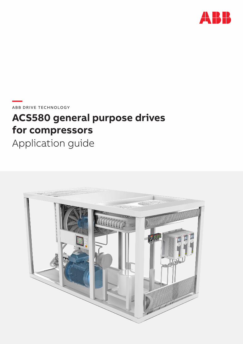
— ABB DRIVE TECHNOLOGY ACS580 general purpose drives for compressors Application guide
Transcript of for compressors Application guide - ABB Ltd · for compressors Application guide . ... 7...
— ABB DRIVE TECHNOLOGY
ACS580 general purpose drives for compressorsApplication guide
2 AC S 5 8 0 G E N E R A L PU R P O S E D R I V E S FO R CO M PR E S S O R S A PPL I C ATI O N G U I D E
— Contents
3 ACS580 general purpose drives – a perfect match for compressors
3 Introduction
4 Why choose a variable frequency converter?
4 Energy savings4 Process productivity4 Elimination of mechanical drive components5 Extended equipment lifetime and reduced maintenance5 Adjustable motor load capacity curves
6 Features and customers benefits of using the ACS580
6 Firmware and programmability6 Energy efficiency and load analyzer6 Support for energy-efficient motors6 Hexagonal flux control mode7 Temperature monitoring7 PFC control7 Adaptive programming
8 How do I use the ACS580’s features and customer benefits?
8 PFC10 Temperature monitoring11 Monitoring temperature using the CMOD-02 module11 Monitoring temperature using a direct connection to the control terminals12 Activating the temperature monitoring graph13 ATEX-approved module for monitoring temperature in potentially explosive environments14 Load analyzer15 Energy efficiency16 EnergySave tool17 Hexagonal flux control mode18 DriveSize for dimensioning

3
—ACS580 general purpose drives – a perfect match for compressors
IntroductionTypical applications of ACS580 drives are square torque and basic constant torque applications such as compressors, pumps and fans. ACS580 drives are designed to be virtually plug-in-ready drives which makes them easy to install, startup and use. They offer users effortless performance through easy installation and commissioning as well as through the wide range of built-in features. Many of these features are designed for specific applications or environments. They reduce the time users need to spend adjusting the settings, and they also reduce the need for additional investments in external components.
The purpose of this application guide is to give the reader a broad overview of the specific features of the ACS580 general purpose drives that are useful especially for compressor users. The application guide introduces the main features and benefits of using them and it also offers step-by-step introductions on how to apply each feature.
The application guide consists of three chapters. The first chapter explains why you should choose a variable speed drive to control various processes. It introduces energy savings as a growing trend and explains how variable speed drives enable different loadability curves. The second chapter briefly highlights some of the main features of ACS580 drives that make them desirable for compressors. Finally, the thirdchapter focuses more on the aforementioned features and shows in detail how to apply each of them.
A compressor specific brochure is also available that includes more information about compressors as applications and what ABB offers for them. It can be accessed via ABB’s website at www.abb.com/drives and also by following the QR code on the back cover of this application guide.

4 AC S 5 8 0 G E N E R A L PU R P O S E D R I V E S FO R CO M PR E S S O R S A PPL I C ATI O N G U I D E
—Why choose a variable frequency converter?
Energy savingsIf the AC motor-driven application doesn’t continuously require the full speed, the energy can be saved by controlling the motor with a variable speed drive. This way, the speed of the motor can be matched to the process needs rather than running the motor at full speed all the time.
As much as one-fifth of a factory’s energy bill can be attributed to the production of compressed air. Using a variable speed drive to control the speed of a compressor saves energy and money compared to a fixed speed equivalent. It can be economically viable to fit variable speed drives to air compressors where the average loading is 75 percent of capacity or less.
Process productivityWhether in production or use of compressed air, there are typically many opportunities to improve productivity and cut costs, since compressed air is often the most expensive utility. Incorrect dimensioning, small leaks, pressure problems, and inadequate uses of compressed air as well as ineffective control are only the tip of the iceberg for inefficiencies related to compressed air.
With variable speed drives, the varying demand for compressed air can be better matched. There is no need for mechanical process control methods, and power surges during the startup of the AC motor can also be reduced. Variable speed drives allow precise pressure control and often a lower pressure setpoint. The more exact the pressure control, the bigger the energy savings, as a good match between the process demand
—Nowadays, productivity, efficiency and energy savings form the center of discussion. It is important to improve efficiency, and at the same time consume less energy and cut costs. Variable speed drives (VSDs), also known as variable frequency converters (VFCs) and variable frequency drives (VFDs) enable all these, as well as extending equipment lifetime and reducing the need for maintenance.
and the process control eliminates waste. Furthermore, the lower pressure setpoint significantly reduces leakage.
Elimination of mechanical drive componentsSince variable speed drives allow the motor speed to correspond to the load requirements, there is no need for expensive mechanical drive components such as gearboxes. The elimination of these speed-increasing and -decreasing devices cuts maintenance costs and saves floor space.
— Did you know?
A simple way to obtain energy savings is to use ACS580 variable speed drives to intelligently control motors. ACS580 drives regulate the speed of a motor, which often lowers a compres-sor’s pressure setpoint and energy consumption. Further-more, leakage losses, which can be up to 25 percent of the output of an industrial compressed air system, can be significantly reduced by a lower pressure setpoint.

Ad
just
able
mo
tor
load
cur
ves
Ener
gy
savi
ngs
Process productivity
Adjustable speed
Extended equipment lifetime
Reduced maintenance
Cost savings
Benefits of choosing a variable speed drive
Exac
t p
roce
ss
cont
rol
5
Extended equipment lifetime and reduced maintenanceUsing single-speed starting methods, motors start sharply and are easily exposed to a high starting torque and current. The starting current can be as much as ten times the full load current. A high starting current causes enormous heat in the motor, which, along with mechanical stress, further reduces the lifetime of the motor.
On the other hand, with variable speed drives the user is able to define the acceleration time, during which the variable speed drive gradually ramps the motor speed up to the operational speed. Due to the controlled starting current, electrical and mechanical stress are reduced. This improves the lifetime of the motor, and also reduces maintenance and repair costs.
Adjustable motor load capacity curvesIf the motor is driven without a variable speed drive, its load capacity curves cannot be modified and the energy consumption cannot be effectively optimized. The motor will produce a specified torque at a certain speed, and the maximum torque cannot be exceeded.
With a variable speed drive, on the other hand, there are different loading options. The standard curve (Curve 1), can be used continuously. Other curves can only be used for certain periods of time because the motor’s cooling system is notdesigned for this kind of heavy use.
In certain applications, sometimes as much as twice the amount of torque is required during startup. With a variable speed drive this is possible, meaning that motors can be dimensioned according to their normal use. This reduces the investment cost.
To be able to use these features, it is very important that the load, the variable speed drive and the motor are compatible. Otherwise the motor or the drive will overheat and be damaged.
—Figure 1: ACS580 offering includes a broad range of drives in differentsizes.—Figure 2: Motor load capacity curves when used with an AC drive.
Precise process controlThe process control offered by variable speed drives stands out compared to other control methods. Users can accurately define how the motor is run in different situations in order tofulfil their process needs. For example, users can select for a precise motor speed, an exact stopping position and a specific amount of torque depending on the requirements.
In addition, ACS580 drives have a PID function, which is useful for many compressor, pump and fan applications. In the PID control, based on actual feedback collected from the process,such as pressure levels, the ACS580 drive is able to precisely hold the setpoint the user defines. This prevents estimation errors from resulting in damage to the process.
T/Tn
f (Hz)
Curve 1
Curve 2
Curve 3
Load
—Figure 2
—Figure 1
6 AC S 5 8 0 G E N E R A L PU R P O S E D R I V E S FO R CO M PR E S S O R S A PPL I C ATI O N G U I D E
—Features and customers benefits of using the ACS580
—ACS580 general purpose drives offer a wide range of different features that help customers adjust the drive for their needs. For compressor users the most useful features are temperature monitoring, PFC control, and hexagonal flux control. It is also possible to monitor the real-time energy consumption and you use the results to reduce the operating costs. The following takes a closer look at these features and the benefits that the features enable.
Firmware and programmabilityCompressor users can easily optimize the drive to the compressor requirements. ACS580 general purpose drives have plenty of in-built features that reduce the need to purchase additional external control logic. Along with this simplicity, the compressors can be also monitored and increased protection can be applied based on the monitoring results. Early monitoring also enables the user to perform preventative maintenance and reduce unexpected downtime.
The standard ACS580 firmware includes, for example, maintenance counters, stall protection, configurable supervision functions, motor temperature monitoring, fault loggers, motor preheating, a PFC feature for compressor control, a PID function, and an energy savings estimator. User can also utilize flying start in both scalar and vector control modes, load curve monitoring to detect abnormal load situations, and adaptive programming for advanced configuration. Users can even define different access levels for different user groups.
Energy efficiency and load analyzerThe energy efficiency function together with the EnergySave tool allow the user first to estimate potential energy savings and then to monitor the savings achieved and optimize energy consump-tion while running the motor. With these features, the user gets valuable information about the amount of energy and money saved and can further reduce operating costs through consumption optimization.
The load analyzer function, which is accessible via the control panel or a PC, displays histograms as well peak values of selected signals and indicates how the motor has been run in a given period of time. This feature is useful for monitoring unexpected loads and pointing out if there are some dimensioning issues.
Support for energy-efficient motorsACS580 general purpose drives support SynRM motors as well as permanent magnet motors. In permanent magnet motors, rare earth permanent magnets are designed into the motor’s rotor, eliminating the need for a magnetizing current, and therefore there is no rotor current. This means that very little heat is transferred to the rest of the motor and bearings, which immediately improves the motor’s energy efficiency.
In SynRM motors, there are no magnets at all, and therefore there is no loss due to magnetization. In these motors, there are no torque, speed ripple nor cogging like there usually are with permanent magnet motors. All these lead to reduced rotor losses and heat production, which enables longer greasing intervals and improves energy efficiency.
Hexagonal flux control modeThis control mode utilizes a “six-step” control method that enables access to an extra voltage reserve when operated in an area with field weakening. In this area, due to a decrease in the current and a lower switching frequency,

Temperature monitoring sensors, maximum of three
ACS580 featuresfor compressors
SynRM andPM support
Loadanalyzer
Tem
per
atur
em
oni
tori
ng
Hexagonal fluxcontrol mode
EnergySavecalculator
Ad
apti
vep
rog
ram
min
g
PFCcontrol
Ener
gy
effi
cien
cyca
lcul
ato
r
7
it is possible to improve efficiency. This is also a useful feature if an extra boost is needed, for example, to increase the cooling capacity of a compressor. With the help of the hexagonal flux control mode, the motor does not need to be overdimensioned according to the highest possible load.
Temperature monitoringThe temperature monitoring function is typically used in air compressors since it enables temperature protection of the motor or mechanics without additional I/O components. The function monitors the motor temperature in real time and sets a fault or warning if a user-defined temperature is passed. This prevents overheating and damage to the motor caused by increased motor temperature. The monitored temperature can be also seen in a graph, from which the motor temperature behavior during the process can be analyzed.
ACS580 general purpose drives have direct sensor connectivity to PTC and Pt100 sensors. They also have an ATEX-certified PTC connection option that allows the drive to control an application used in an environment with an explosive atmosphere. The ATEX-certified CPTC-02 thermistor protection module enhances process safety and removes the need to build a safety circuit with separate ATEX-certified components and the need to purchase additional safety a dons, such as safety relays.
PFC controlPFC control is an ideal feature for multi-compressors as it enables a wide air volume supply with fewer components. PFC control is designed to manage situations where there is a lot of fluctuation in the process requirement that cannot be served with only one motor. The PFC starts and stops additional DOL motors depending on the need. The ACS580 standard firmware includes a PFC macro that changes all the relevant parameters and settings automatically. This means that deploying this feature requires only a few clicks on the assistant control panel.
Adaptive programmingIf the aforementioned features do not fulfil your needs, adaptive programming helps you do even more. It is a small-scale drive programming tool with function blocks and sequence states for cases where setting basic parameters is not enough. With the Drive composer pro software, users can utilize pre-defined inputs and outputs for on-board I/O and design extra functions to match the process requirements. Adaptive programming tool offers great help, for example, in compressor retrofit cases. This tool is extremely simple to use and no programming background is needed.

8 AC S 5 8 0 G E N E R A L PU R P O S E D R I V E S FO R CO M PR E S S O R S A PPL I C ATI O N G U I D E
—How do I use the ACS580’s features and customer benefits?
—The following paragraphs explain detailed steps for using features that were introduced above. They also show how to adjust settings and features to perfectly fit the user’s needs. The features studied more deeply in this chapter include PFC, temperature monitoring, hexagonal control mode, and the load analyzer, as well as the energy efficiency and EnergySave tools.
PFCThe PFC feature is used in fixed speed compres-sor systems consisting of one drive and multiple motors. The drive controls the speed of one of the motors and connects (and disconnects) the other motors directly to the supply network through contactors. The feature is especially useful when the process demand varies. The PFC control logic switches auxiliary motors on and off as required by the capacity changes in the process.
The following instructions show how to set up the PFC by using the primary settings. The PFC can also be applied by adjusting a set of different parameters; however, utilizing the primary settings saves time and simplifies the process.
Note! The PID function needs to be enabled in order to be able to use the PFC function.
4b) ...set the number of motors (up to 4 motors) and, for example, configure relays and check I/O connections.
4a) By choosing “Configure PFC I/O” you can...
3b) The selection is displayed on the control panel.
3a) To check the configuration of the PFC go, down the primary settings menu list and choose “PFC”.
2) Go down the list and select “PFC”. After selecting PFC, the screen comes back to the primary settings menu.
1) Go to the menu and choose “Primary settings” and then choose “Macro”.
9
5) 6) 7a)
7b) 8a) 8b)
9a) 9b) 10)
11a) 11b)
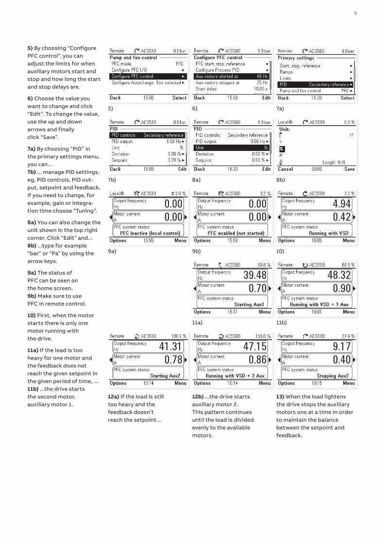
5) By choosing “Configure PFC control”, you can adjust the limits for when auxiliary motors start and stop and how long the start and stop delays are.
6) Choose the value you want to change and click “Edit”. To change the value, use the up and down arrows and finally click “Save”.
7a) By choosing “PID” in the primary settings menu, you can...7b) ... manage PID settings, eg, PID controls, PID out-put, setpoint and feedback. If you need to change, for example, gain or integra-tion time choose “Tuning”.
8a) You can also change the unit shown in the top right corner. Click “Edit” and...8b) ...type for example “bar” or “Pa” by using the arrow keys.
9a) The status of PFC can be seen on the home screen.9b) Make sure to use PFC in remote control.
10) First, when the motor starts there is only one motor running with the drive.
11a) If the load is too heavy for one motor and the feedback does not reach the given setpoint in the given period of time, ...11b) ...the drive starts the second motor, auxiliary motor 1.
13) When the load lightens the drive stops the auxiliary motors one at a time in order to maintain the balance between the setpoint and feedback.
12a) If the load is still too heavy and the feedback doesn’t reach the setpoint...
12b) ...the drive starts auxiliary motor 2. This pattern continues until the load is divided evenly to the available motors.

10 AC S 5 8 0 G E N E R A L PU R P O S E D R I V E S FO R CO M PR E S S O R S A PPL I C ATI O N G U I D E
—How do I use the ACS580’s features and customer benefits?
Temperature monitoringThe ACS580 general purpose drive series can monitor the motor temperature with two sepa-rate functions. The first function utilizes the motor thermal protection model, which gives an estimated temperature derived internally inside the drive. The second function monitors the motor temperature using the sensors installed in the windings. The temperature sensors are connected either to control terminals or to a multifunction module.
The motor temperature can be also monitored using, for example, PTC or Pt100 sensors. The PTC sensors are connected either directly to the control terminals or through a CMOD-02 or CPTC-02 multifunction module, which are both offered as options for the drive. The resistance of the PTC sensors increases as the temperature of the windings increases. The increasing resis-tance of the sensor decreases the voltage at the input, and eventually its state switches from 1 to 0, indicating overheating.
The Pt100 sensors can be connected in series to an analog input and an analog output. The analog output feeds a constant excitation current through the sensor. The sensor tempera-ture increases as the motor temperature rises, as does the voltage over the sensor. The tempera-ture measurement function reads the voltage through the analog input and converts it into degrees Celsius. It is possible to adjust the motor temperature supervision limits and select how the drive reacts when overheating is detected.
The following instructions show how to set parameters to activate the temperature monitoring function. They also explain how to set the graph to show the temperature in real time on the control panel.
—Did you know?
The motor temperature can easily be monitored with various kinds of temperature sensors that are connected either directly to the control terminals or to a CMOD-02 or an ATEX-approved CPTC-02 multifunction module. The monitored temperature can also be drawn, in real time, on the graph displayed on the control panel.
11
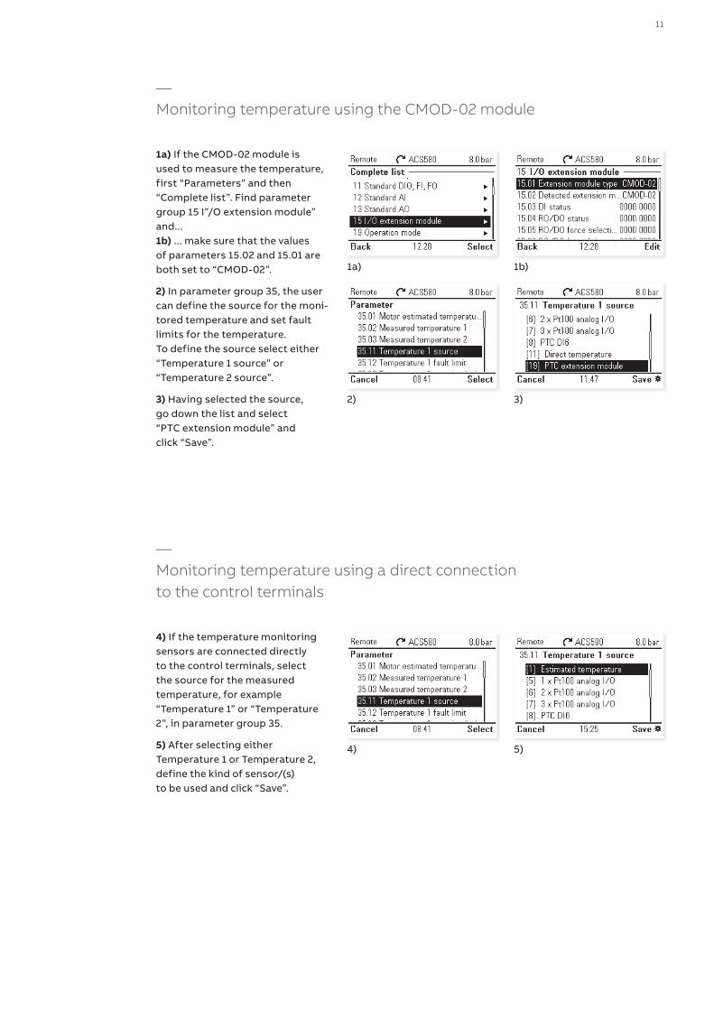
—Monitoring temperature using the CMOD-02 module
1a) If the CMOD-02 module is used to measure the temperature, first “Parameters” and then “Complete list”. Find parameter group 15 I”/O extension module” and...1b) ... make sure that the values of parameters 15.02 and 15.01 are both set to “CMOD-02”.
2) In parameter group 35, the user can define the source for the moni-tored temperature and set fault limits for the temperature. To define the source select either “Temperature 1 source” or “Temperature 2 source”.
3) Having selected the source, go down the list and select “PTC extension module” and click “Save”.
—Monitoring temperature using a direct connection to the control terminals
4) If the temperature monitoring sensors are connected directly to the control terminals, select the source for the measured temperature, for example “Temperature 1” or “Temperature 2”, in parameter group 35.
5) After selecting either Temperature 1 or Temperature 2, define the kind of sensor/(s) to be used and click “Save”.
1a) 1b)
2) 3)
4) 5)
12 AC S 5 8 0 G E N E R A L PU R P O S E D R I V E S FO R CO M PR E S S O R S A PPL I C ATI O N G U I D E
—How do I use the ACS580’s features and customer benefits?
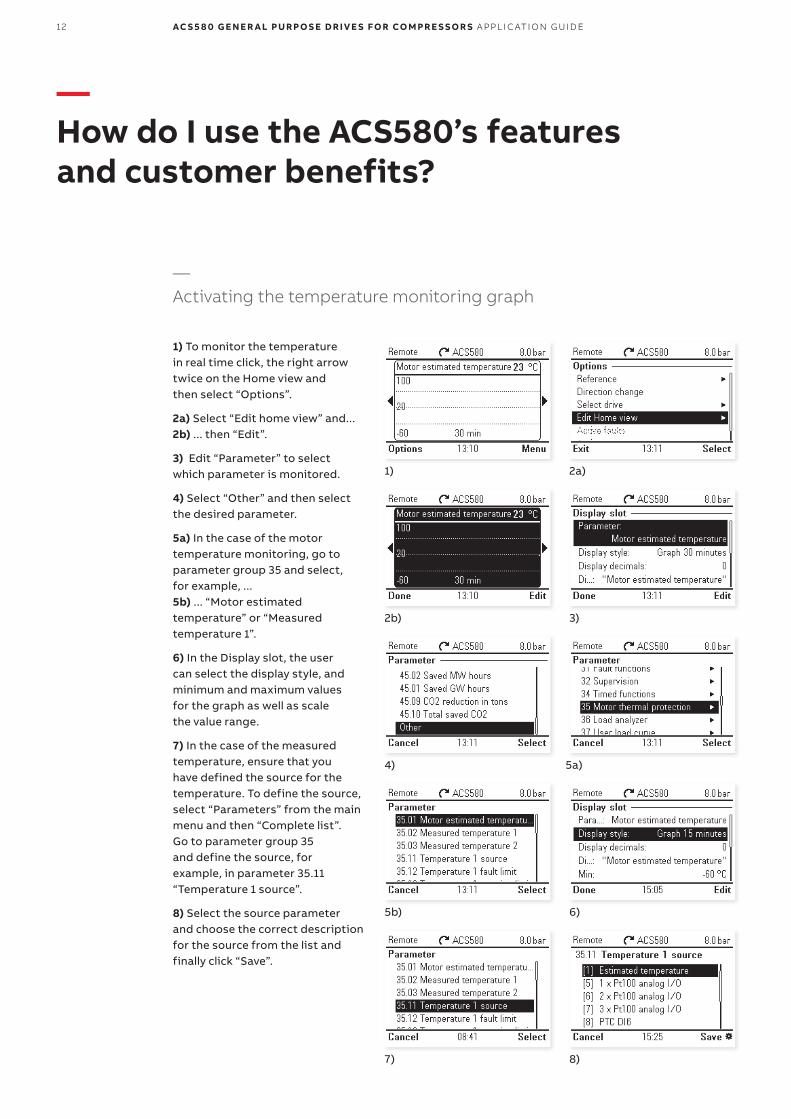
—Activating the temperature monitoring graph
1) To monitor the temperature in real time click, the right arrow twice on the Home view and then select “Options”.
2a) Select “Edit home view” and...2b) ... then “Edit”.
3) Edit “Parameter” to select which parameter is monitored.
4) Select “Other” and then select the desired parameter.
5a) In the case of the motor temperature monitoring, go to parameter group 35 and select, for example, ...5b) ... “Motor estimated temperature” or “Measured temperature 1”.
6) In the Display slot, the user can select the display style, and minimum and maximum values for the graph as well as scale the value range.
7) In the case of the measured temperature, ensure that you have defined the source for the temperature. To define the source, select “Parameters” from the main menu and then “Complete list”. Go to parameter group 35 and define the source, for example, in parameter 35.11 “Temperature 1 source”.
8) Select the source parameter and choose the correct description for the source from the list and finally click “Save”.
1) 2a)
2b) 3)
4) 5a)
5b) 6)
7) 8)
13
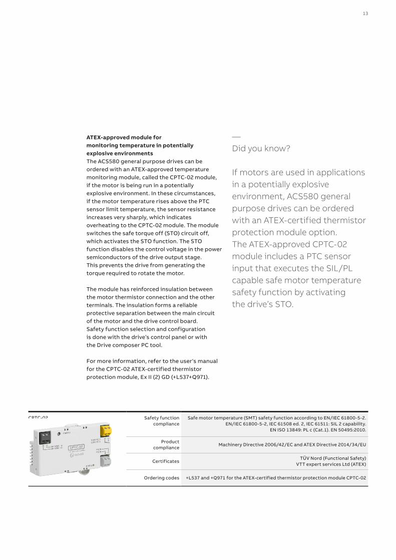
ATEX-approved module for monitoring temperature in potentially explosive environmentsThe ACS580 general purpose drives can be ordered with an ATEX-approved temperature monitoring module, called the CPTC-02 module, if the motor is being run in a potentiallyexplosive environment. In these circumstances, if the motor temperature rises above the PTC sensor limit temperature, the sensor resistance increases very sharply, which indicates overheating to the CPTC-02 module. The module switches the safe torque off (STO) circuit off, which activates the STO function. The STO function disables the control voltage in the power semiconductors of the drive output stage. This prevents the drive from generating the torque required to rotate the motor.
The module has reinforced insulation between the motor thermistor connection and the other terminals. The insulation forms a reliable protective separation between the main circuit of the motor and the drive control board. Safety function selection and configuration is done with the drive’s control panel or with the Drive composer PC tool.
For more information, refer to the user‘s manual for the CPTC-02 ATEX-certified thermistor protection module, Ex II (2) GD (+L537+Q971).
—Did you know?
If motors are used in applications in a potentially explosive environment, ACS580 general purpose drives can be ordered with an ATEX-certified thermistor protection module option. The ATEX-approved CPTC-02 module includes a PTC sensor input that executes the SIL/PL capable safe motor temperature safety function by activating the drive’s STO.
CPTC-02 Safety functioncompliance
Safe motor temperature (SMT) safety function according to EN/IEC 61800-5-2. EN/IEC 61800-5-2, IEC 61508 ed. 2, IEC 61511: SIL 2 capability.
EN ISO 13849: PL c (Cat.1). EN 50495:2010.
Productcompliance
Machinery Directive 2006/42/EC and ATEX Directive 2014/34/EU
CertificatesTÜV Nord (Functional Safety)
VTT expert services Ltd (ATEX)
Ordering codes +L537 and +Q971 for the ATEX-certified thermistor protection module CPTC-02
14 AC S 5 8 0 G E N E R A L PU R P O S E D R I V E S FO R CO M PR E S S O R S A PPL I C ATI O N G U I D E
—How do I use the ACS580’s features and customer benefits?
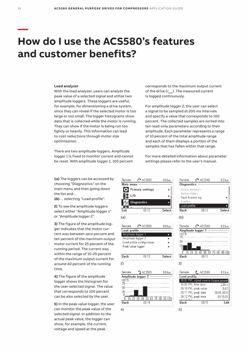
Load analyzerWith the load analyzer, users can analyze the peak value of a selected signal and utilize two amplitude loggers. These loggers are useful, for example, for dimensioning a drive system, since they can reveal if the selected motor is too large or too small. The logger histograms show data that is collected while the motor is running. They can show if the motor is being run too lightly or heavily. This information can lead to cost reductions through motor size optimization.
There are two amplitude loggers. Amplitude logger 1 is fixed to monitor current and cannot be reset. With amplitude logger 1, 100 percent
corresponds to the maximum output current of the drive (Imax ). The measured current is logged continuously.
For amplitude logger 2, the user can select a signal to be sampled at 200 ms intervals and specify a value that corresponds to 100 percent. The collected samples are sorted into ten read-only parameters according to their amplitude. Each parameter represents a range of 10 percent of the total amplitude range and each of them displays a portion of the samples that has fallen within that range.
For more detailed information about parameter settings please refer to the user’s manual.
1a) The loggers can be accessed by choosing “Diagnostics” on the main menu and then going down the list and...1b) ... selecting “Load profile”.
2) To see the amplitude loggers select either “Amplitude logger 1” or “Amplitude logger 2”.
3) The figure of the amplitude log-ger indicates that the motor cur-rent was between zero percent and ten percent of the maximum output motor current for 25 percent of the running period. The current was within the range of 10-20 percent of the maximum output current for around 40 percent of the running time.
4) The figure of the amplitude logger shows the histogram for the user-selected signal. The value that corresponds to 100 percent can be also selected by the user.
5) In the peak value logger, the user can monitor the peak value of the selected signal. In addition to the actual peak value, the logger can show, for example, the current, voltage and speed at the peak.
1a) 1b)
2) 3)
4) 5)
15
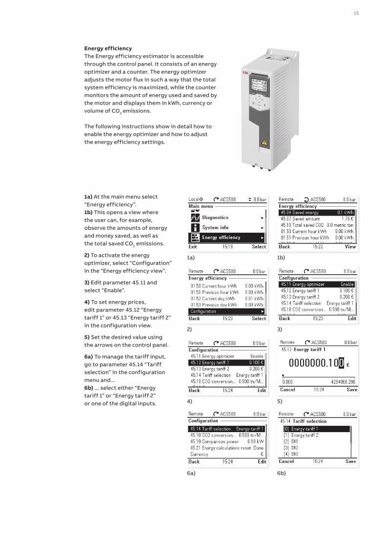
Energy efficiencyThe Energy efficiency estimator is accessible through the control panel. It consists of an energy optimizer and a counter. The energy optimizer adjusts the motor flux in such a way that the total system efficiency is maximized, while the counter monitors the amount of energy used and saved by the motor and displays them in kWh, currency or volume of CO2 emissions.
The following instructions show in detail how to enable the energy optimizer and how to adjust the energy efficiency settings.
1a) At the main menu select “Energy efficiency”.1b) This opens a view where the user can, for example, observe the amounts of energy and money saved, as well as the total saved CO2 emissions.
2) To activate the energy optimizer, select “Configuration” in the “Energy efficiency view”.
3) Edit parameter 45.11 and select “Enable”.
4) To set energy prices, edit parameter 45.12 “Energy tariff 1” or 45.13 “Energy tariff 2” in the configuration view.
5) Set the desired value using the arrows on the control panel.
6a) To manage the tariff input, go to parameter 45.14 “Tariff selection” in the configuration menu and...6b) ... select either “Energy tariff 1” or “Energy tariff 2” or one of the digital inputs.
1a) 1b)
2) 3)
4) 5)
6a) 6b)

16 AC S 5 8 0 G E N E R A L PU R P O S E D R I V E S FO R CO M PR E S S O R S A PPL I C ATI O N G U I D E
—How do I use the ACS580’s features and customer benefits?
EnergySave toolIn addition to the energy efficiency estimator that is offered with the ACS580 standard soft-ware, ABB also offers access to the EnergySave tool. EnergySave is an ideal feature for calculating how much energy and money you could save by using ABB drives. It allows the user to compare AC drive control against traditional flow control methods in different applications, such as compressors.
There are two modes of the EnergySave tool available: basic and advanced. The basic mode does not require a lot of technical data about the application and you can quickly see potential savings. The advanced mode gives you the opportunity to include your technical details for a more specific calculation.
—Did you know?
The EnergySave tool is also available from Google Play and the Apple App Store.
• The EnergySave tool for compressors can be accessed - through the energy efficiency page:
http://new.abb.com/drives/energy-efficiency
- or directly via the following link: http://energysave.abb-drives.com/ #/compressor
17
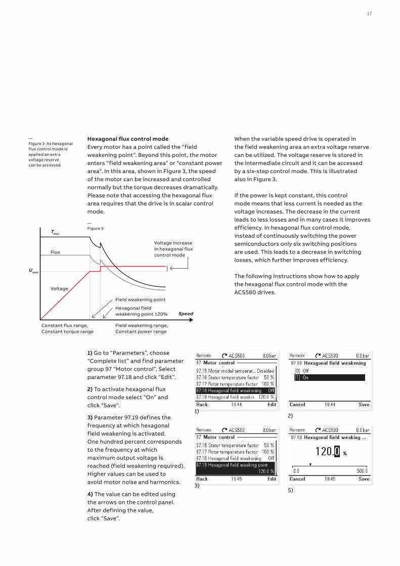
Hexagonal flux control modeEvery motor has a point called the “field weakening point”. Beyond this point, the motor enters “field weakening area” or “constant power area”. In this area, shown in Figure 3, the speed of the motor can be increased and controlled normally but the torque decreases dramatically. Please note that accessing the hexagonal flux area requires that the drive is in scalar control mode.
When the variable speed drive is operated in the field weakening area an extra voltage reserve can be utilized. The voltage reserve is stored in the intermediate circuit and it can be accessed by a six-step control mode. This is illustrated also in Figure 3.
If the power is kept constant, this control mode means that less current is needed as the voltage increases. The decrease in the current leads to less losses and in many cases it improves efficiency. In hexagonal flux control mode, instead of continuously switching the power semiconductors only six switching positions are used. This leads to a decrease in switching losses, which further improves efficiency.
The following instructions show how to apply the hexagonal flux control mode with the ACS580 drives.
—Figure 3: As hexagonal flux control mode is applied an extra voltage reserve can be accessed.
Flux
Tmax
Voltage
Constant flux range,Constant torque range
Field weakening range,Constant power range
Field weakening point
Speed
Unom}
Voltage increase in hexagonal flux control mode
Hexagonal field weakening point 120%
—Figure 3
1) Go to “Parameters”, choose “Complete list” and find parameter group 97 “Motor control”. Select parameter 97.18 and click “Edit”.
2) To activate hexagonal flux control mode select “On” and click “Save”.
3) Parameter 97.19 defines the frequency at which hexagonal field weakening is activated. One hundred percent corresponds to the frequency at which maximum output voltage is reached (field weakening required). Higher values can be used to avoid motor noise and harmonics.
4) The value can be edited using the arrows on the control panel. After defining the value, click “Save”.
1)2)
3)5)
18 AC S 5 8 0 G E N E R A L PU R P O S E D R I V E S FO R CO M PR E S S O R S A PPL I C ATI O N G U I D E
—How do I use the ACS580’s features and customer benefits?
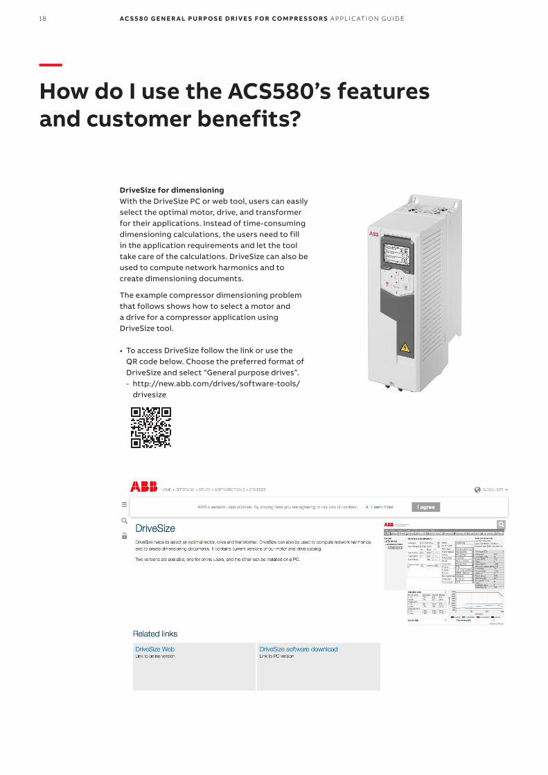
DriveSize for dimensioningWith the DriveSize PC or web tool, users can easily select the optimal motor, drive, and transformer for their applications. Instead of time-consuming dimensioning calculations, the users need to fill in the application requirements and let the tool take care of the calculations. DriveSize can also be used to compute network harmonics and to create dimensioning documents.
The example compressor dimensioning problem that follows shows how to select a motor and a drive for a compressor application using DriveSize tool.
• To access DriveSize follow the link or use the QR code below. Choose the preferred format of DriveSize and select “General purpose drives”. - http://new.abb.com/drives/software-tools/
drivesize
19
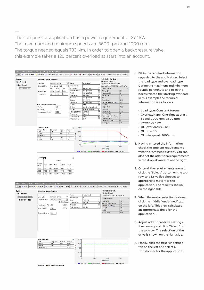
—The compressor application has a power requirement of 277 kW. The maximum and minimum speeds are 3600 rpm and 1000 rpm. The torque needed equals 733 Nm. In order to open a backpressure valve, this example takes a 120 percent overload at start into an account.
1. Fill in the required information regarded to the application. Select the load type and overload type. Define the maximum and minimum rounds per minute and fill in the boxes related the starting overload. In this example the required information is as follows.
- Load type: Constant torque - Overload type: One-time at start - Speed: 1000 rpm, 3600 rpm - Power: 277 kW - OL (overload) %: 120 - OL time: 10 - OL min speed: 3600 rpm
2. Having entered the information, check the ambient requirements with the “Ambient button”. You can also set the additional requirements in the drop-down lists on the right.
3. Once all the requirements are set, click the “Select” button on the top row, and DriveSize chooses an appropriate motor for the application. The result is shown on the right side.
4. When the motor selection is done, click the middle “undefined” tab on the left. This view calculates an appropriate drive for the application.
5. Adjust additional drive settings if necessary and click “Select” on the top row. The selection of the drive is shown on the right side.
6. Finally, click the first “undefined” tab on the left and select a transformer for the application.

—www.abb.com/ACS580www.abb.com/driveswww.abb.com/drivespartnerswww.abb.com/motors&generators3A
UA
00
00
204
743
RE
V B
EN
01.
11.2
017
© Copyright 2017 ABB. All rights reserved.Specifications subject to change without notice.
Online manuals for ACS580 drives
Video playlist: ACS580 how-to videos
Compressor specific brochure