FOR BOARD-TO-CABLE CONNECTION - Fujitsu Global BOARD-TO-CABLE CONNECTION 230R SERIES (CONFORMS TO...
20
1 Dimensions are in millimeters (inches) www.fcai.fujitsu.com Specifications subject to change FOR BOARD-TO-CABLE CONNECTION 230R SERIES (CONFORMS TO SCSI) ■ MATERIALS Item Insulator Conductor Plating Materials Polyester (UL94V-0) Copper alloy Contact Terminal Gold plating Palladium plating ■ FEATURES • 1.27 mm × 2.54 mm (0.050 in. × 0.100 in.) pitch contact arrangement enables high-density mounting. • Cables and connectors are assembled by means of discrete wire IDC. • Terminals are spaced in a four-row staggered arrangement (2.54 mm × 1.905 mm) (0.100 in. × 0.075 in.). • Knife-fork two-point contacts are highly reliable. • One-touch lock types and screw lock types are available for fixing the board-side connector and the cable-side connector. • The following connectors conform to the SCSI standards recommended by ANSI: (1) Single-operation lock types • 50-contact type:Conforms to the A-cable connectors prescribed in SCSI-II and SCSI-III • 68-contact type:Conforms to the B-cable connectors prescribed in SCSI-II (2) Screw lock types • 68-contact type:Conforms to the P/Q-cable connectors prescribed in SCSI-III * SCSI: Small Computer System Interface ■ SPECIFICATIONS Specifications –55°C to +105°C DC 1 A AC 240 V 30 mΩ max. (DC 6 V, 0.1A) 1000 MΩ min. (DC 500 V) AC 750 V for 1 minute AWG #28 and #30 twisted-pair cables with φ 0.5 to 0.88 mm (0.020 to 0.035 in.) sheath diameter. (The applicable wires depend on the number of contacts. See the descriptions of IDC plugs and metal covers.) Item Operating temperature range Current rating Voltage rating Contact resistance Insulation resistance Dielectric withstand voltage Applicable wire (standard)
Transcript of FOR BOARD-TO-CABLE CONNECTION - Fujitsu Global BOARD-TO-CABLE CONNECTION 230R SERIES (CONFORMS TO...

1Dimensions are in millimeters (inches) www.fcai.fujitsu.comSpecificationssubject to change
FOR BOARD-TO-CABLE CONNECTION
230R SERIES (CONFORMS TO SCSI)
MATERIALS
Item
Insulator
Conductor
Plating
Materials
Polyester (UL94V-0)
Copper alloy
Contact
Terminal
Gold plating
Palladium plating
FEATURES
• 1.27 mm × 2.54 mm (0.050 in. × 0.100 in.) pitch contactarrangement enables high-density mounting.
• Cables and connectors are assembled by means ofdiscrete wire IDC.
• Terminals are spaced in a four-row staggeredarrangement (2.54 mm × 1.905 mm) (0.100 in. × 0.075in.).
• Knife-fork two-point contacts are highly reliable.• One-touch lock types and screw lock types are available
for fixing the board-side connector and the cable-sideconnector.
• The following connectors conform to the SCSIstandards recommended by ANSI:
(1) Single-operation lock types• 50-contact type:Conforms to the A-cable connectors
prescribed in SCSI-II and SCSI-III• 68-contact type:Conforms to the B-cable connectors
prescribed in SCSI-II(2) Screw lock types• 68-contact type:Conforms to the P/Q-cable connectors
prescribed in SCSI-III* SCSI: Small Computer System Interface
SPECIFICATIONS
Specifications
–55°C to +105°C
DC 1 A
AC 240 V
30 mΩ max. (DC 6 V, 0.1A)
1000 MΩ min. (DC 500 V)
AC 750 V for 1 minute
AWG #28 and #30 twisted-paircables with φ 0.5 to 0.88 mm (0.020to 0.035 in.) sheath diameter.(The applicable wires depend onthe number of contacts. See thedescriptions of IDC plugs and metalcovers.)
Item
Operating temperature range
Current rating
Voltage rating
Contact resistance
Insulation resistance
Dielectric withstand voltage
Applicable wire (standard)

2
230R Series (Conforms to SCSI)
Dimensions are in millimeters (inches) www.fcai.fujitsu.comSpecificationssubject to change
STRAIGHT SOCKET (SINGLE-OPERATION LOCK TYPE) DIMENSIONS
A
B
D
E
No. 1
No. 2
No. 3
End terminal
C
10.5
(0.4
13)
5 (0.1
96)
5.50
(0.2
16)
3.4
(0.1
33)
3.8
(0.1
49)
1.27 (0.050)
5.1
(0.2
00)
2-No. 2-56UNC
Unit: mm (in.)
MOUNTING HOLE LAYOUT (COMPONENT SIDE)
Unit: mm (in.)
PATTERN INHIBITED AREAS RECOMMENDED PANEL DIMENSIONS
Unit: mm (in.)Unit: mm (in.)
2.85 –0
(0.112 –0)3.30 –0
(0.129 –0)
11.1
–0
(0.4
37 –
0 )
Thickness of recommended panel: t = 1 (0.04)
(E + 0.5) ±0.1 ((E + 0.019) ±0.004)
B ±0.1 (±0.004)
8.3 ±
0.1
(0.
326
±0.0
04)
R 1.5
±0.1
(R 0
.059
±0.0
04 )
PART NUMBERS AND DIMENSIONSNumber ofcontacts
202628405068
Part number
FCN-234D020-G/EFCN-234D026-G/EFCN-234D028-G/EFCN-234D040-G/EFCN-234D050-G/EFCN-234D068-G/E
Dimensions: mm (in.)D
15.60 (0.614)19.41 (0.764)20.68 (0.814)28.30 (1.114)34.65 (1.364)46.08 (1.814)
E23.24 (0.914)27.05 (1.064)28.32 (1.114)35.94 (1.414)42.29 (1.664)53.72 (2.114)
C11.46 (0.451)15.24 (0.600)16.51 (0.650)24.13 (0.950)30.48 (1.200)41.91 (1.650)
B27.43 (1.079)32.24 (1.269)32.51 (1.279)40.13 (1.479)46.48 (1.829)57.91 (2.279)
A33.40 (1.314)37.21 (1.464)38.48 (1.514)46.10 (1.841)52.45 (2.064)63.88 (2.514)
This series includes connectors with M 2.5 threaded inserts for mounting on PC boards and panels. Specify a part number by replacing -G/E atthe end with -G/C.Example: FCN-234D050-G/C
B ±0.1 (±0.004)
C ±0.1 (±0.004)
No. 1
26 and 50 contacts
B ±0.1 (±0.004)
C ±0.1 (±0.004)
No. 1
20, 28 and 68 contacts
1.90
5 ±0.
1
(0.0
75 ±
0.00
4 )
1.27 ±0.1
(0.050 ±0.004)
1.90
5 ±0.
1
(0.0
75 ±
0.00
4 )
1.27 ±0.1
(0.050 ±0.004)
φ2.8(φ0.110 )
φ0.8 ±0.06
(φ.031 ±0.002)
φ2.8(φ0.110 )
φ0.8 ±0.06
(φ.031 ±0.002)

2-3
2
63.88 (2.514)
1.27 (0.050)
1.27 (0.050)
8.74(0.344)
2-No.2-56UNC1st Contact Z
Z
57.91 (2.279)41.91 (1.633)
5.5
(0.2
16)
1.905(0.075)
5.51
(0.2
16 )
5 (0
.196
)3.
8 (0
.149
)
3.4
(0.1
33)46.08 (1.814)
41.91 (1.650)
54.21 ±0.1 (2.124 ±0.004)
57.91 ±0.1 (2.279 ±0.004)
R2.2 ±0.1
(R0.086 ±0.004)
7.5 ±
0.1
(0.0
86 ±
0.00
4 )
41.91 ±0.1 (1.633 ±0.004)
1.90
5 ±0.
1
(0.0
75 ±
0.00
4 )
Position of pin1
1.27 ±0.05(.050 ±0.001)
φ0.8 ±0.06
(φ.031 ±0.002)
63.88 (2.514)
57.91 (2.279)41.91 (1.633)
46.08 (1.814)
41.91 (1.650) 1.905(0.075)
1.27 (0.050)
1.27 (0.050)
5.5(
0.21
6)
8.74(0.344)
5.51
(0.2
16 )
5 (0
.196
)3.
8 (0
.149
)
3.4
(0.1
33)
2-No.2-56UNC1st Contact Z
Z
8.74(0.344)
2-No.4-4OUNC1st Contact Z
Z
63.88 (2.514)
57.91 (2.279)41.91 (1.633)
1.27 (0.050)
1.27 (0.050)
5.5(
0.21
6)
46.08 (1.814)
41.91 (1.650) 1.905(0.075)
5 (0
.196
)3.
8 (0
.149
)
3.4
(0.1
33)
54.21 ±0.1 (2.134 ±0.004)
57.91 ±0.1 (2.279 ±0.004)
R2.2 ±0.1
(R0.086 ±0.004)
7.5 ±
0.1
(0.
295
±0.0
04)
54.21 ±0.1 (2.134 ±0.004)
57.91 ±0.1 (2.279 ±0.004)
R2.2 ±0.1
(R0.086 ±0.004)
7.5 ±
0.1
(0.
295
±0.0
04)
FCN-234D068-G/P*** 68 CONTACT STRAIGHT TYPE, BOARD-SOCKET, SCREW TYPE LOCK
DIMENSIONS
PANEL LAYOUT MOUNTING HOLE LAYOUT
DIMENSIONS
PANEL LAYOUT
PART NO.: FCN-234D068-G/P#DO PART NO.: FCN-234D068-G/P
PART NO.: FCN-234D068-G/P#DO
PANEL/THICKNESS: t = 1.5mm PANEL/THICKNESS: t = 1.5mm
PANEL/THICKNESS: t = 1.5mm
1.45
(0.
057)
1.905 ±0.3
(0.075 ±0.011)
4.75
(0.1
87 )
No. 2-56UNC
6.0
(0.2
36 )
2.4
(0.0
94 )
3.99
(0.1
57 )
5.5
(0.2
16 )
φ 4(φ 0.157 )
1.47
(0
.057
)
No. 4-40UNC
Jack Socket FCN-230A24SECTION Z-Z (5/1)
Unit: mm (in.)
Unit: mm (in.)
Unit: mm (in.)
Unit: mm (in.)
Unit: mm (in.)
Unit: mm (in.)

4
230R Series (Conforms to SCSI)
Dimensions are in millimeters (inches) www.fcai.fujitsu.comSpecificationssubject to change
RIGHT ANGLE SOCKET (SINGLE-OPERATION LOCK TYPE) DIMENSIONS
Unit: mm (in.)
MOUNTING HOLE LAYOUT (COMPONENT SIDE)
Unit: mm (in.)
PATTERN INHIBITED AREAS RECOMMENDED PANEL DIMENSIONS
(E + 0.5) ±0.1 ((E + 0.019) ±0.004)
Thickness of recommended panel: t = 1 mm (0.039 in.)
B ±0.1 (±0.004)
8.3 ±
0.1
(0.
326
±0.0
04)
R 1.5
±0.1
(R 0
.059
±0.0
04 )
3.5
mm
(0
.138
in.)
max
.
B ±0.1 (±0.004)
6.8 –0
(0.267 –0)3.2 –0
(0.125 –0) 6 –0
(0.0
23 –
0 ) 3
.2 –
0
(0.1
25 –
0 )
1.90
5 ±0
.1
(.07
5 ±0
.004
)
Unit: mm (in.) Unit: mm (in.)
PART NUMBERS AND DIMENSIONSNumber ofcontacts
202628405068
Part number
FCN-235D020-G/EFCN-235D026-G/EFCN-235D028-G/EFCN-235D040-G/EFCN-235D050-G/EFCN-235D068-G/E
Dimensions: mm (in.)D
15.60 (0.614)19.41 (0.764)20.68 (0.814)28.30 (1.114)34.65 (1.364)46.08 (1.814)
E23.24 (0.914)27.05 (1.064)28.32 (1.114)35.94 (1.414)42.29 (1.664)53.72 (2.114)
C11.46 (0.451)15.24 (0.600)16.51 (0.650)24.13 (0.950)30.48 (1.200)41.91 (1.650)
B27.43 (1.079)32.24 (1.269)32.51 (1.279)40.13 (1.479)46.48 (1.829)57.91 (2.279)
A33.40 (1.314)37.21 (1.464)38.48 (1.514)46.10 (1.841)52.45 (2.064)63.88 (2.514)
This series includes connectors with M 2.5 threaded inserts for mounting on PC boards and panels. Specify a part number by replacing -G/E atthe end with -G/C.Example: FCN-235D050-G/C
A
B
DNo. 1No. 2No. 3
End terminal
10.5
(0.4
13)
C
E
0.7
(0.0
27)
6.60
5 (0
.602
)
B
1.90
5(0
.075
)
1.27 (0.050)
5.5
(0.2
16)
5 (0
.196
)
2-No. 2-56UNC
12.3
0(0
.484
)
4.70
(0.
185)
0.40
(0
.015
)
0.40 (0.015)
4.37 (0.173)
5.10
(0.
200)
3.4 (0.133)
2-No. 2-56UNC
B ±0.1 (±0.004)
26 and 50 contacts
C ±0.1 (±0.004)
3.5
mm
(0.1
38 in
.) m
ax.
End terminal
No. 3
No. 2
No. 1
B ±0.1 (±0.004)
20, 28, 40, and 68 contacts
C ±0.1 (±0.004)
3.5
mm
(0.1
38 in
.) m
ax.
End terminal
No. 3
No. 2
No. 1
φ2.8(φ0.110 )
1.90
5 ±0.
1
(0.0
75 ±
0.00
4 )
1.27 ±0.1(0.050 ±0.004)
φ0.8 ±0.06
(φ.031 ±0.002)
φ2.8(f0.110 )
1.90
5 ±0.
1
(0.0
75 ±
0.00
4 )
1.27 ±0.1(0.050 ±0.004)φ0.8 ±0.06
(φ.031 ±0.002)

5
230R Series (Conforms to SCSI)
Dimensions are in millimeters (inches) www.fcai.fujitsu.comSpecificationssubject to change
(E + 0.5) ±0.1 ((E + 0.019) ±0.004)
B ±0.1 ( ±0.004)
8.3
±0.1
( 0.
326±
0.00
4 )
R 1.5
±0.1
(R 0
.059
±0.0
04 )
Thickness of recommended panel: t = 1 mm (0.039 in.)
3.5
mm
(0
.138
in.)
max
.
B ±0.1 (±0.004)
6.8 –0
(0.267 –0)3.2 –0
(0.125 –0) 6 –0
(0.0
23 –
0 ) 3
.2 –
0
(0.1
25 –
0 )
1.90
5 ±0
.1
(.07
5 ±0
.004
)
RIGHT-ANGLE SOCKET WITH BOARD LOCK BRACKET (SINGLE-OPERATION LOCK TYPE) DIMENSIONS
Unit: mm (in.)
MOUNTING HOLE LAYOUT (COMPONENT SIDE)
Unit: mm (in.)
PATTERN INHIBITED AREAS RECOMMENDED PANEL DIMENSIONS
Unit: mm (in.) Unit: mm (in.)
PART NUMBERS AND DIMENSIONSNumber ofcontacts
202628405068
Part number
FCN-235D020-G/HFCN-235D026-G/HFCN-235D028-G/HFCN-235D040-G/HFCN-235D050-G/HFCN-235D068-G/H
Dimensions: mm (in.)D
15.60 (0.614)19.41 (0.764)20.68 (0.814)28.30 (1.114)34.65 (1.364)46.08 (1.814)
E23.24 (0.914)27.05 (1.064)28.32 (1.114)35.94 (1.414)42.29 (1.664)53.72 (2.114)
C11.46 (0.451)15.24 (0.600)16.51 (0.650)24.13 (0.950)30.48 (1.200)41.91 (1.650)
B27.43 (1.079)32.24 (1.269)32.51 (1.279)40.13 (1.479)46.48 (1.829)57.91 (2.279)
A33.40 (1.314)37.21 (1.464)38.48 (1.514)46.10 (1.841)52.45 (2.064)63.88 (2.514)
This series includes connectors with M2.5 threaded inserts for mounting panels. Specify a part number by replacing -G/H at the end with -G/J.Example: FCN-235D050-G/J
A
B
DNo. 1
No. 2
No. 3
End terminal
2-No. 2-56UNG
10.
50
(0.4
13)
C
0.40(0.015)
E
0.70
(0.
027)
6.60
5 (0
.260
)
B
12.3
0(0
.484
)
4.70
(0.
185)
0.40
(0
.015
)
Thickness of board: t = 1.6 mm (0.063 in.)
4.37 (0.173)
1.27 (0.050 )
1.90
5(0
.075
)
5.5
(0.2
16)
5.10
(0.
200)
5 (0
.196
)
3.4 (0.133)
3.00(0.118)
2-No. 2-56UNG
B ±0.1 (±0.004)
26 and 50 contacts
C ±0.1 (±0.004)
3.5
(0.1
3) m
ax.
End terminal
φ3.05
(φ0.120 )
φ3.05
(φ0.120 )
No. 3
No. 2
No. 1
B ±0.1 (±0.004)
20, 28,40, and 68 contacts
C ±0.1 (±0.004)
End terminal
No. 3
No. 2
No. 1
3.5
(0.1
3) m
ax.
1.90
5 ±0.
1
(0.0
75 ±
0.00
4 )
1.27 ±0.05(0.050 ±0.001)
φ0.8 ±0.06
(φ.031 ±0.002)
1.90
5 ±0.
1
(0.0
75 ±
0.00
4 )
1.27 ±0.05(0.050 ±0.001)
φ0.8 ±0.06
(φ.031 ±0.002)

6
230R Series (Conforms to SCSI)
Dimensions are in millimeters (inches) www.fcai.fujitsu.comSpecificationssubject to change
B
B
1st Contact
2-No.4-40UNC
5.5
(0.2
16 )
10.5
(0.4
13 )
C
0.4 (0.015 )
D5
(0.1
96 )
12.3
(0.4
84 )
3.4 (0.133 )
1.75 (0.068 )1 (0.039 )
A
0.7
(0
.039
)6.
605
(0.2
60 )
F
1.27 (0.050)
1.9
05
(0.0
75 )
5.51
(0
.216
)
E ±0.1 (±0.004)
B ±0.1 (±0.004)
R2.2 ±0.1
(R0.086 ±0.004)
7.5 ±
0.1
(0.
295
±0.0
04)
B ±0.1 (±0.004)
C ±0.1 (±0.004)
3.5
(0.1
3) m
ax.
1st CONTACT POSITION
8±0.05
(.314 ±0.001)
1st CONPOSITION
1.27 ±0.1(.050 ±0.004)
φ0.8 ±0.06
(φ.031 ±0.002)
φ3.05 ±0.1
(φ.120 ±0.004)
1.90
5 ±0
.1
(.07
5 ±0
.004
)
A ±0.1 (±0.004)
6.8 –0
(0.267 –0)3.2 –0
(0.125 –0) 6 –0
(0.0
23 –
0 ) 3
.2 –
0
(0.1
25 –
0 )3.
5 m
m
(0.1
38 in
.) m
ax.
1.90
5 ±0
.1
(.07
5 ±0
.004
)
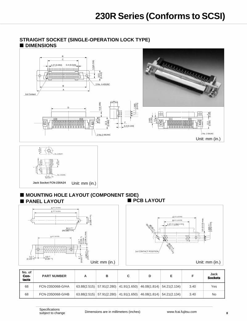
FCN-235D-G/** RIGHT ANGLE, BOARD-SOCKET, METAL SHELL, BOARDLOCKS(40 PinMII/100 base T std) (68 Pin SCSI III std) DIMENSIONS
PANEL LAYOUT PCB LAYOUT
Unit: mm (in.) Unit: mm (in.)
Unit: mm (in.)
4.75
(0.1
87 )
No. 2-56UNC
6.0
(0.2
36 )
2.4
(0.0
94 )
3.99
(0.1
57 )
5.5
(0.2
16 )
φ 4(φ 0.157 )
1.47
(0
.057
)
No. 4-40UNC
Jack Socket FCN-230A24
fo.oN-noCstcat
REBMUNTRAP A B C D E F kcaJstekcoS
04 N-RSAH/G-040D532-NCF )518.1(01.64 )038.1(31.04 )059.0(31.42 )411.1(03.82 )434.1(34.63 45.2 DELLATSNI
04 N-RAH/G-040D532-NCF )518.1(01.64 )038.1(31.04 )059.0(31.42 )411.1(03.82 )434.1(34.63 04.3 DELLATSNI
04 N-RSBH/G-040D532-NCF )518.1(01.64 )038.1(31.04 )059.0(31.42 )411.1(03.82 )434.1(34.63 45.2 —
04 N-RBH/G-040D532-NCF )518.1(01.64 )038.1(31.04 )059.0(31.42 )411.1(03.82 )434.1(34.63 04.3 —
86 N-RSAH/G-860D532-NCF )515.2(88.36 )082.2(19.75 )056.1(19.14 )418.1(80.64 )431.2(12.45 45.2 DELLATSNI
86 N-RAH/G-860D532-NCF )515.2(88.36 )082.2(19.75 )056.1(19.14 )418.1(80.64 )431.2(12.45 04.3 DELLATSNI
86 N-RSBH/G-860D532-NCF )515.2(88.36 )082.2(19.75 )056.1(19.14 )418.1(80.64 )431.2(12.45 45.2 —
86 N-RBH/G-860D532-NCF )515.2(88.36 )082.2(19.75 )056.1(19.14 )418.1(80.64 )431.2(12.45 04.3 —

7
230R Series (Conforms to SCSI)
Dimensions are in millimeters (inches) www.fcai.fujitsu.comSpecificationssubject to change
RIGHT-ANGLE SOCKET (SCREW LOCK TYPE) DIMENSIONS
Unit: mm (in.)
MOUNTING HOLE LAYOUT (COMPONENT SIDE)
57.91 ±0.1 (2.279 ±0.004)41.73 ±0.1 (1.642 ±0.004)
Position of pin 2Position of pin 1
3.5
mm
(0
.138
in.)
max
.
Thickness of board : t = 1.6 mm (0.063 in.)
2-φ3.0
(2-φ0.118 )
1.90
5 ±0.
1
(0.0
75 ±
0.00
4 )
1.27 ±0.1 (0.050 ±0.004)
φ0.8 ±0.06
(φ.031 ±0.002)
Unit: mm (in.)Unit: mm (in.)
PATTERN INHIBITED AREAS
RECOMMENDED PANEL DIMENSIONS
Unit: mm (in.)
54.21 ±0.1 (2.134±0.004)
57.91 ±0.1 (2.279±0.004)
Thickness of recommended panel: t = 1.5 mm (0.059 in.)
7.5
±0.1
(0.2
95±0
.004
)
R 2.2 ±0.1
(R 0.086±0.004)
57.91 ±0.1 (2.279 ±0.004 )
3.5
mm
(0
.138
in.)
max
. 6.8 –0
(0.267 –0)3.2 –0
(0.125 –0) 6 –0
(0.0
23 –
0 ) 3
.2 –
0
(0.1
25 –
0 )
1.90
5 ±0
.1
(.07
5 ±0
.004
)
PART NUMBER
FCN-235D068-G/EA
NUMBER OF CONTACTS
68 contacts
Note: Remove the spacer to mount the connectoron the panel, then tighten the hexagon nuts.Make sure that the panel is sandwichedbetween the connector and nuts.
63.88 (2.514)
57.91 (2.279)
41.91 (1.633)
46.08 (1.814)2-No. 2-56UNC
No. 1
2-No. 2-56UNC
10.
50
(0.4
13)
0.40(0.015)
1.27(0.050)
5.5
(0.
216)
12.3
0(0
.484
) 4.70
(0.1
85)
4.37 (0.173)
1.90
5(0
.075
)5(0
.196
)
0.40
(0
.015
)
5.51
(0.2
16)
3.4(0.133)
0.70
(0.0
27)
6.60
5(0
.260
)
8
230R Series (Conforms to SCSI)
Dimensions are in millimeters (inches) www.fcai.fujitsu.comSpecificationssubject to change
STRAIGHT SOCKET (SINGLE-OPERATION LOCK TYPE) DIMENSIONS
Unit: mm (in.)
MOUNTING HOLE LAYOUT (COMPONENT SIDE)
B
B
1st Contact
2-No. 4-40UNC
10.5
(0.4
13)
C
0.4 (0.015)
A
F
D12
.3(0
.484
)
2-No.2-56UNC
0.7
(0.0
27)
1.27 (0.050)
5.5(
0.21
6)
5 (0
.196
)
1.90
5(0
.075
)
3.4 (0.133)
5(0
.196
)12
.3(0
.484
)
2-No. 2-56UNC
0.7
(0.0
27)
6.60
5(0
.260
)
A ±0.1 (±0.004)
E ±0.1 (±0.004)
R2.2 ±0.1
(R0.086 ±0.004)
7.5 ±
0.1
(0.
295
±0.0
04)
3.5
(0.1
3) m
ax.
1st CONTACT POSITION
B ±0.1 (±0.004)
A ±0.1 (±0.004)
1.27 ±0.1(.050 ±0.004)
φ0.8 ±0.06
(φ.031 ±0.002)
φ3.05 ±0.1
(φ.120 ±0.004) 1.90
5 ±0
.1
(.07
5 ±0
.004
)
3.5
mm
(0
.138
in.)
max
.
A ±0.1 (±0.004)
6.8 –0
(0.267 –0)3.2 –0
(0.125 –0) 6 –0
(0.0
23 –
0 ) 3
.2 –
0
(0.1
25 –
0 )
1.90
5 ±0
.1
(.07
5 ±0
.004
)
PANEL LAYOUT PCB LAYOUT
4.75
(0.1
87 )
No. 2-56UNC
6.0
(0.2
36 )
2.4
(0.0
94 )
3.99
(0.1
57 )
5.5
(0.2
16 )
φ 4(φ 0.157 )
1.47
(0
.057
)
No. 4-40UNC
Jack Socket FCN-230A24
Unit: mm (in.)Unit: mm (in.)
Unit: mm (in.)
fo.oN-noC -noC -noC -noC -noCstcat stcat stcat stcat stcat
REBMUNTRAP A B C D E F kcaJstekcoS stekcoS stekcoS stekcoS stekcoS
86 AH/G-860D532-NCF )515.2(88.36 )082.2(19.75 )056.1(19.14 )418.1(80.64 )431.2(12.45 04.3 seY
86 BH/G-860D532-NCF )515.2(88.36 )082.2(19.75 )056.1(19.14 )418.1(80.64 )431.2(12.45 04.3 oN

9
230R Series (Conforms to SCSI)
Dimensions are in millimeters (inches) www.fcai.fujitsu.comSpecificationssubject to change
FCN-237R**-G/* IDC TYPE, CABLE-PLUG DIMENSIONS
Unit: mm (in.)
PART NUMBERS AND DIMENSIONS
B
C
1.27(0.50)
D
E
2.54(0.100)
9.00(0.354)
5.70
(0.2
24)
6.90
(0.2
72)
Number 3 contact
C
13.7
5(0
.541
)4.
9(0.
193)
9.00(0.354)
Main Body
Number 2 contact
Number 1 contactEnd contact
Cover 1
Assembled Part
Cover 2
fo.oNstcatnoC
foretemaiDlanretxEeriWdeilppA REBMUNTRAP
).ni(mmsnoisnemiD
A B C D E
02
φ mm88.0ot8.0)530.0ot130.0( F/G-020R732-NCF
)956.0(57.61 )054.0(34.11 )738.0(52.12 )226.0(08.51 )966.0(00.71mm56.0ot5.0)620.0ot020.0( E/G-020R732-NCF
mm97.0ot66.0)030.0ot620.0( G/G-020R732-NCF
62
mm88.0ot8.0)530.0ot130.0( F/G-620R732-NCF
)908.0(56.02 )006.0(42.51 )789.0(60.52 )227.0(16.91 )918.0(18.02mm56.0ot5.0
)620.0ot020.0( E/G-620R732-NCF
82
mm88.0ot8.0)530.0ot130.0( F/G-820R732-NCF
)958.0(38.12 )056.0(15.61 )730.1(33.62 )228.0(88.02 )968.0(80.22mm56.0ot5.0
)620.0ot020.0( E/G-820R732-NCF
04
mm88.0ot8.0)530.0ot130.0( F/G-040R732-NCF
)951.1(54.92 )059.0(31.42 )773.1(59.33 )221.1(05.82 )961.1(07.92mm97.0ot66.0)030.0ot620.0( G/G-040R732-NCF
05
mm88.0ot8.0)530.0ot130.0( F/G-050R732-NCF
)904.1(08.53 )002.1(84.03 )785.1(03.04 )785.1(58.43 )914.1(50.63mm56.0ot5.0)620.0ot020.0( E/G-050R732-NCF
mm97.0ot66.0)030.0ot620.0( G/G-050R732-NCF
86
mm88.0ot8.0)530.0ot130.0( F/G-860R732-NCF
)958.1(32.74 )056.1(19.14 )730.2(37.15 )228.1(82.64 )968.1(84.74mm56.0ot5.0)620.0ot020.0( E/G-860R732-NCF
mm97.0ot66.0)030.0ot620.0( G/G-860R732-NCF
001
mm88.0ot8.0)530.0ot130.0( F/G-001R732-NCF
)956.2(55.76 )054.2(32.26 )738.2(50.27 )226.2(06.66 )966.2(08.76mm56.0ot5.0
)620.0ot020.0( E/G-001R732-NCF

10
230R Series (Conforms to SCSI)
Dimensions are in millimeters (inches) www.fcai.fujitsu.comSpecificationssubject to change
METAL COVER (ONE-TOUCH LOCK TYPE) DIMENSIONS
PART NUMBERS AND DIMENSIONS
B
A
C B AE D 3 4 51 2
C
D7.
5(0
.295
)10.0
(0.393)
B
32.5
(1.
279)
32.5
(1.
279)
12.0(0.472)
10.0(0.393)
12.0(0.472)
C
DA
Indent
The D/E type has indents to prevent incorrect insertion.
[A/E or C/E type]
[D/E type]
Unit: mm (in.)
Dimensions: mm (in.)Number ofcontacts
20
26
28
40
50
68
Part number
FCN-230C020-A/EFCN-230C020-C/EFCN-230C026-C/EFCN-230C028-A/EFCN-230C028-C/EFCN-230C040-C/EFCN-230C050-A/EFCN-230C050-C/EFCN-230C050-D/EFCN-230C068-A/EFCN-230C068-C/EFCN-230C068-D/E
A
28.95 (1.139)
32.76 (1.298)
34.03 (1.339)
41.65 (1.639)
48.00 (1.889)
59.43 (2.339)
B
21.15 (0.832)
24.96 (0.982)
26.23 (1.032)
33.85 (1.332)
40.20 (1.582)
51.63 (2.032)
C6.5 × 4.5 (0.255 × 0.177)8.5 × 8.2 (0.334 × 0.322)7.2 × 8.5 (0.283 × 0.334)6.5 × 6.0 (0.255 × 0.236)7.2 × 8.5 (0.289 × 0.334)9.0 × 10.0 (0.354 × 0.393)8.5 × 7.0 (0.334 × 0.275)10.0 × 9.7 (0.395 × 0.381)14.7 × 10.4 (0.585 × 0.409)9.0 × 8.0 (0.354 × 0.314)10.0 × 9.0 (0.395 × 0.354)14.7 × 10.4 (0.585 × 0.409)

11
230R Series (Conforms to SCSI)
Dimensions are in millimeters (inches) www.fcai.fujitsu.comSpecificationssubject to change
BACKSHELL KIT (METAL CAN , PLASTIC SLIDE ON BOOT)SCSI II DIMENSIONS
A
8.4
B
10(0.393)
12(0.472) Cover (12)
Cover (11)
View of A
C
D
Locking leverFlat head machine screw
A
-11(-0.433)
4°E
Unit: mm (in.)
Unit: mm (in.)
φ 9.
8 (0
.386
)
11.5
(0.
453)
42 (
1.65
4)
38 (1.496)
48.7 (1.917)
Outer cover
Cable clamp
Latch
Innner cover (2)
Innner cover (1)
Pan head machine screw
32 (
1.25
9)
Tooling RequiredCrimping Tool PlateFCN-237T-T094/HArbor PressFCN-707T-T101/H
METAL OBTUSE ANGLE CABLE OUT COVER (SINGLE-OPERATION LOCK TYPE) DIMENSIONS
Part Number: FCN-230C050-E/SC
PART NUMBERS AND DIMENSIONSNumber ofcontacts
4050
Part number
FCN-230C040-L/EFCN-230C050-L/E
Dimensions: mm (in.)D
6.34 (0.249)6.70 (0.263)
E19°15°
C10.60 (0.417)11.38 (0.448)
B33.80 (1.330)35.50 (1.397)
A41.65 (1.639)48.00 (1.889)

12
230R Series (Conforms to SCSI)
Dimensions are in millimeters (inches) www.fcai.fujitsu.comSpecificationssubject to change
EMI/ESD RESISTANT COVER (SCREW LOCK TYPE)SCSI III 68 POSITION DIMENSIONS
Unit: mm (in.)
65.41 (2.575)
57.91 (2.575)
15.6
2(0
.614
)
36 (
1.41
7)2.
7 (0
.105
)
38.4 (1.511)
46.43 (1.827)
12(0.472)
3.3
(0.1
29)
16(0.629)
φ14(φ0.551)
Cable clamp
Outer cover
Pan head machine screw
Inner cover 1
Inner cover 2
Locking screw
FCN-237R068-G/No. 2-56UNC
PART NUMBERS
* Applicable cable: External diameter ø12.3 mm (ø0.484 in.)
rebmuntraP elbaCelbacilppA
S/E-860C032-NCF ).ni484.0Ø(mm3.21Ø
AS/E-860C032-NCF ).ni254.0Ø(mm5.11Ø

13
230R Series (Conforms to SCSI)
Dimensions are in millimeters (inches) www.fcai.fujitsu.comSpecificationssubject to change
ACCESSORY (DUST CAP FOR SOCKET) (230R SERIES AND 240R SERIES)
Used to prevent dust from entering the contact section of a socket connector.
DIMENSIONS
A
B
9.1
(0.
362)
1.3
(0.0
51)
3.8
(0.1
49)
1 (0
.039
)
15°
7.9
(0.
311)
4-R2 (4-R0.078)
Material : PolypropyleneColor : Sand beige
Unit: mm (in.)
PART NUMBERS AND DIMENSIONSNumber ofcontacts
28365068
Part number
FCN-230C028-11FCN-230C036-11FCN-230C050-11FCN-230C068-11
Dimensions: mm (in.)A
35.7 (1.405)40.8 (1.606)49.7 (1.956)61.1 (2.405)
B30.1 (1.185)35.2 (1.385)44.1 (1.736)55.5 (2.185)
APPLICATIONS
FCN-234D0 × × -G/CFCN-244D0 × × -G/EFCN-235D0 × × -G/CFCN-245D0 × × -G/E
Dust capFCN-230C0 × × -11

14
230R Series (Conforms to SCSI)
Dimensions are in millimeters (inches) www.fcai.fujitsu.comSpecificationssubject to change
CABLE ASSEMBLY TOOLS
The following tools are needed to assemble FCN-230/230R/240/240R series connectors.
• Cable aligner (semiautomatic cable aligner or hand tool)• IDC tool
1. Cable Aligner
Item
FCN-237J
FCN-237R
FCN-247J
FCN-247R
Body/Controller
FCN-M561-A/C
Bed
FCN-P560-2/A
FCN-P560-2/J
Adaptor
FCN-K560-A-xxx
FCN-K560-R-xxx
FCN-K560-K-xxx
FCN-K560-J-xxx
Semiautomatic cable alignerHand tool
FCN-237T-T062/H
FCN-247T-T061/H
2. Insulation Displacement Connection (IDC) tool
Item
FCN-237J
FCN-237R
FCN-237D
FCN-247J
FCN-247R
FCN-247D
Hand press
FCN-237T-T109/H
Head/Table
FCN-237T-T064/H
FCN-237T-T067/H
FCN-237T-T075/H
FCN-247T-T066/H
FCN-247T-T068/H
FCN-247T-T077/H
• Cable aligner • Insulation displacement connection (IDC) tool
xxx indicates the number of contacts.

15
230R Series (Conforms to SCSI)
Dimensions are in millimeters (inches) www.fcai.fujitsu.comSpecificationssubject to change
Stand
Applicator
Cover 1Cover 2
Clamp section
Clamp leverWires
Cable key
Sinking combApplicator
Bed
Lock
Lever
GuideStopper
Handle
Semi-Automatic ToolsCable Aligning Machine
Main Body (FCN-M551-120, FCN-M551-220)
Head (FCN-H550-1/A Stand (FCN-D550)
Applicator (FCN-A550-1/A-xxx) IDC Tool (FCN-237T-T109/H,FCN-237T-T067/H locator)
1. Set the applicator on the stand.Set covers 1 and 2 in the applicator.
2. Push the wire into the sinkingcombs.
3. Set the applicator onto theinstallation table and begincable alignment
4. Take the covers off theapplicator.
5. Put covers together andpre-assemble them tothe connector body.
6. Conduct final aaembly as shown.
Semi-automatic-Medium LevelBody: :FCN-M551-120Head Assembly: :FCN-H550Applicator: :FCN-A550-1/A-***(***: 020, 028, 036, 050, 068, 080)Stand: :FCN-D550
.oNsoP eriWdeilppA)mm:.aiDeriw( )mm:.aiDeriw( )mm:.aiDeriw( )mm:.aiDeriw( )mm:.aiDeriw(
traProtcennoCrebmun rebmun rebmun rebmun rebmun
rengilAelbaClooTCDI
looTdnaH otuA-imeS
02|86
03#ro82#)88.0ot8.0(
F/G-020R732-NCF|
F/G-860R732-NCF H/260T-T732-NCF|
H/340t-t732-NCF)*wolebeeS(
:SSERPDNAHH/901T-T732-NCF:rotacoL&DAEHH/760T-T732-NCF03#ro82#
)56.0ot5.0(
E/G-020R732-NCF|
E/G-860R732-NCF
FCN-230R SERIES SCSI II CABLE CONNECTORSSOCKET: FCN-237R***-G/E, G/F (***: 020, 026, 028, 050, 068)

16
230R Series (Conforms to SCSI)
Dimensions are in millimeters (inches) www.fcai.fujitsu.comSpecificationssubject to change
EMI/ESD RESISTANT COVER DIMENSIONS
Number of contacts: 50 contactsPart number: FCN-230C050-E/S
35.00 (1.409)
54.00 (2.126)
Cable clamp
Outer cover (2)
φ10.50 (0.512)
15.00(0.591)
46.48 (1.830)
No. 2-56UNCLock screw
Inner cover 2
Inner cover 1
Pan head machine screw (2)
12.00(0.472)
3.30
(0
.130
)
36.0
0 (1
.417
)2.
70(0
.106
)32
.00
(1.2
60)
15.6
2(0
.615
)
Unit: mm (in.)
Number of contacts: 100 contactsPart number: FCN-230C100-E/S
85.73 (3.375)
Cable clamp
Outer cover (2)
φ13 (0.512)
No. 2-56UNC Lock screw
Inner cover 2
Inner cover 1
Pan head machine screw (2)
78.23 (3.080)
36.0
0 (1
.417
)2.
70(0
.106
)32
.00
(1.2
60)
15.6
2(0
.615
)
15.00(0.591)
12.00(0.472)
3.7
3(0
.147
)
17.00(0.699)
42.00 (1.654)
66.75 (2.628) Unit: mm ((in.)
This series includes connectors with No.4-40UNC lock screws. Specify a part number by replacing -E/S at the end with -F/S.Example: FCN-230C100-F/S

17
230R Series (Conforms to SCSI)
Dimensions are in millimeters (inches) www.fcai.fujitsu.comSpecificationssubject to change
RIGHT-ANGLE SOCKET WITH HEXAGONAL NUTS FOR BOARD LOCK DIMENSIONS
When mounting a connector on a panel, remove the hexagonal nuts and spacers. After mountingon the panel, replace and tighten the hexagonal nuts. Unit: mm (in.)
MOUNTING HOLE LAYOUT (COMPONENT SIDE)
End terminal
No. 3
No. 2
No. 1
B ±0.1 (±.004)
C ±0.1 (±.004)
3.5
mm
(0.
138
in.)
max
.50 contacts
End terminal
No. 3
No. 2
No. 1
B ±0.1 (±.004)
C ±0.1 (±.004)
3.5
mm
(0.
138
in.)
max
.100 contacts
1.27 ±0.1
(0.50±0.004)
φ0.8 ±0.06
(φ0.031 ±0.002)
1.90
5 ±0
.1 (0
.075
±0.0
04)
1.90
5 ±0
.1 (0
.075
±0.0
04)
φ3.0
(φ0.118)
φ0.8 ±0.06
(φ0.031 ±0.002)
φ3.00
(φ0.118)
Unit: mm (in.)
PATTERN INHIBITED AREAS RECOMMENDED PANEL DIMENSIONS
Unit: mm (in.)
(B – 3.7) ±0.1 (( – 0.146)±.004)
B ±0.1 (±.004)
7.5
±0.1
(0.2
95±.
004 )
R 1.4
±0.1 (0
.055
±.004 )
Thickness of recommended panel: t = 1.5 mm (0.059 in.)Unit: mm (in.)
B ±0.1 ( ±0.004)
6.0 –0
(0.236–0)2.7 –0
(0.106–0)
3.3
–0
(0.1
30–0
)
11.6
–0
(0.4
57–0
)
PART NUMBERS AND DIMENSIONSNumber ofcontacts
50100
Part number
FCN-235D050-G/P#BAFCN-235D100-G/P#BA
Dimensions: mm (in.)A
52.45 (2.065)84.20 (3.315)
B46.48 (1.830)78.23 (3.080)
C30.48 (1.200)62.23 (2.450)
D34.65 (1.364)66.40 (2.614)
This series includes connectors with No.4-40UNC screws for hexagonal nuts. Specify a part number by replacing#BA at the end with #AA.Example: FCN-235D100-G/P#AA
A
B
C
1.27 (0.050)End terminal
No. 3
No. 2No. 1
0.40(0.015)
5.50
(0.2
16)
8.74
(0.3
44)
2-No. 2-56UNCD
B
Spacer Spacer6.
605
(0.2
60)
11.7
0(0
.460
)5.
0(0
.196
)
5.51
(0.2
16)
4.70
(0.
185)
1.90
5 (0
.075
)
0.40
(0.
015)
2.88 (0.113)
3.40 (0.133)Thickness of board: t=1.6 mm (0.063 in.)
4.37(0.179)

18
230R Series (Conforms to SCSI)
Dimensions are in millimeters (inches) www.fcai.fujitsu.comSpecificationssubject to change
RIGHT-ANGLE SOCKET WITH HEXAGONAL NUTS FOR BOARD LOCK DIMENSIONS
When mounting a connector on a panel, remove the hexagonal nuts and spacers. After mountingon the panel, replace and tighten the hexagonal nuts. Unit: mm (in.)
MOUNTING HOLE LAYOUT (COMPONENT SIDE)
End terminal
No. 3
No. 2
No. 1
B ±0.1 (±.004)
C ±0.1 (±.004)
3.5
mm
(0.
138
in.)
max
.50 contacts
End terminal
No. 3
No. 2
No. 1
B ±0.1 (±.004)
C ±0.1 (±.004)
3.5
mm
(0.
138
in.)
max
.100 contacts
1.27 ±0.1
(0.50±0.004)
φ0.8 ±0.06
(φ0.031 ±0.002)
1.90
5 ±0
.1 (0
.075
±0.0
04)
1.90
5 ±0
.1 (0
.075
±0.0
04)
φ3.0
(φ0.118)
φ0.8 ±0.06
(φ0.031 ±0.002)
φ3.00
(φ0.118)
Unit: mm (in.)
PATTERN INHIBITED AREAS RECOMMENDED PANEL DIMENSIONS
Unit: mm (in.)
(B – 3.7) ±0.1 (( – 0.146)±.004)
B ±0.1 (±.004)
7.5
±0.1
(0.2
95±.
004 )
R 1.4
±0.1 (0
.055
±.004 )
Thickness of recommended panel: t = 1.5 mm (0.059 in.)Unit: mm (in.)
B ±0.1 ( ±0.004)
6.0 –0
(0.236–0)2.7 –0
(0.106–0)
3.3
–0
(0.1
30–0
)
11.6
–0
(0.4
57–0
)
PART NUMBERS AND DIMENSIONSNumber ofcontacts
50100
Part number
FCN-235D050-G/P#BAFCN-235D100-G/P#BA
Dimensions: mm (in.)A
52.45 (2.065)84.20 (3.315)
B46.48 (1.830)78.23 (3.080)
C30.48 (1.200)62.23 (2.450)
D34.65 (1.364)66.40 (2.614)
This series includes connectors with No.4-40UNC screws for hexagonal nuts. Specify a part number by replacing#BA at the end with #AA.Example: FCN-235D100-G/P#AA
A
B
C
1.27 (0.050)End terminal
No. 3
No. 2No. 1
0.40(0.015)
5.50
(0.2
16)
8.74
(0.3
44)
2-No. 2-56UNCD
B
Spacer Spacer6.
605
(0.2
60)
11.7
0(0
.460
)5.
0(0
.196
)
5.51
(0.2
16)
4.70
(0.
185)
1.90
5 (0
.075
)
0.40
(0.
015)
2.88 (0.113)
3.40 (0.133)Thickness of board: t=1.6 mm (0.063 in.)
4.37(0.179)

19
230R Series (Conforms to SCSI)
Dimensions are in millimeters (inches) www.fcai.fujitsu.comSpecificationssubject to change
EMI/ESD RESISTANT COVER DIMENSIONS
Number of contacts: 50 contactsPart number: FCN-230C050-E/S
35.00 (1.409)
54.00 (2.126)
Cable clamp
Outer cover (2)
φ10.50 (0.512)
15.00(0.591)
46.48 (1.830)
No. 2-56UNCLock screw
Inner cover 2
Inner cover 1
Pan head machine screw (2)
12.00(0.472)
3.30
(0
.130
)
36.0
0 (1
.417
)2.
70(0
.106
)32
.00
(1.2
60)
15.6
2(0
.615
)
Unit: mm (in.)
Number of contacts: 100 contactsPart number: FCN-230C100-E/S
85.73 (3.375)
Cable clamp
Outer cover (2)
φ13 (0.512)
No. 2-56UNC Lock screw
Inner cover 2
Inner cover 1
Pan head machine screw (2)
78.23 (3.080)
36.0
0 (1
.417
)2.
70(0
.106
)32
.00
(1.2
60)
15.6
2(0
.615
)
15.00(0.591)
12.00(0.472)
3.7
3(0
.147
)
17.00(0.699)
42.00 (1.654)
66.75 (2.628) Unit: mm ((in.)
This series includes connectors with No.4-40UNC lock screws. Specify a part number by replacing -E/S at the end with -F/S.Example: FCN-230C100-F/S
20
230R Series (Conforms to SCSI)
Dimensions are in millimeters (inches) www.fcai.fujitsu.comSpecificationssubject to change
© 2007 Fujitsu Components America, Inc. All rights reserved. All trademarks or registered trademarks are the prop-erty of their respective owners. Fujitsu Components America, Inc. or its affiliates do not warrant that the content of thedatatasheet is error free. In a continuing effort to improve our products, Fujitsu Components America, Inc. or itsaffiliates reserve the right to change specifications/datasheets witout prior notice. Rev. November 2, 2007.
JapanFujitsu Component LimitedGotanda-Chuo Building3-5, Higashigotanda 2-chome, Shinagawa-kuTokyo 141-0022, JapanTel: (81-3) 5449-7010Fax: (81-3) 5449-2626Email: [email protected]: www.fcl.fujitsu.com
North and South AmericaFujitsu Components America, Inc.250 E. Caribbean DriveSunnyvale, CA 94089 U.S.A.Tel: (1-408) 745-4900Fax: (1-408) 745-4970Email: [email protected]: http://us.fujitsu.com/components
EuropeFujitsu Components Europe B.V.Diamantlaan 252132 WV HoofddorpNetherlandsTel: (31-23) 5560910Fax: (31-23) 5560950Email: [email protected]: emea.fujitsu.com/components
Asia PacificFujitsu Components Asia Ltd.102E Pasir Panjang Road#01-01 Citilink Warehouse ComplexSingapore 118529Tel: (65) 6375-8560Fax: (65) 6273-3021Email: [email protected]
Fujitsu ComponentsInternationalHeadquarterOffices