for BMW E9x 335i/xi N54bd8ba3c866c8cbc330ab-7b26c6f3e01bf511d4da3315c66902d6.r6.cf1.r… · for BMW...
15
R Installation Procedures Left Vent Vacuum/Boost Gauge Part Numbers left ES2588091 right ES2594189 for BMW E9x 335i/xi N54 (2007-2011) This tutorial is provided as a courtesy by ECS Tuning. Proper service and repair procedures are vital to the safe, reliable operation of all motor vehicles as well as the personal safety of those performing the repairs. Standard safety procedures and precautions (including use of safety goggles and proper tools and equipment) should be followed at all times to eliminate the possibility of personal injury or improper service which could damage the vehicle or compromise its safety. Although this material has been prepared with the intent to provide reliable information, no warranty (express or implied) is made as to its accuracy or completeness. Neither is any liability assumed for loss or damage resulting from reliance on this mate- rial. SPECIFICALLY, NO WARRANTY OF MERCHANTABILITY, FITNESS FOR A PARTICULAR PURPOSE OR ANY OTHER WARRANTY IS MADE OR TO BE IMPLIED WITH RESPECT TO THIS MATERIAL. In no event will ECS Tuning, Incorporated or its affiliates be liable for any damages, direct or indirect, consequential or compensatory, arising out of the use of this material.
-
Upload
phungkhuong -
Category
Documents
-
view
216 -
download
0
Transcript of for BMW E9x 335i/xi N54bd8ba3c866c8cbc330ab-7b26c6f3e01bf511d4da3315c66902d6.r6.cf1.r… · for BMW...

R
Installation Procedures Left Vent Vacuum/Boost Gauge
Part Numbers
left ES2588091right ES2594189
for BMWE9x 335i/xi N54
(2007-2011)
This tutorial is provided as a courtesy by ECS Tuning.
Proper service and repair procedures are vital to the safe, reliable operation of all motor vehicles as well as the personal safety of those performing the repairs. Standard safety procedures and precautions (including use of safety goggles and proper tools and equipment) should be followed at all times to eliminate the possibility of personal injury or improper service which could damage the vehicle or compromise its safety.
Although this material has been prepared with the intent to provide reliable information, no warranty (express or implied) is made as to its accuracy or completeness. Neither is any liability assumed for loss or damage resulting from reliance on this mate-rial. SPECIFICALLY, NO WARRANTY OF MERCHANTABILITY, FITNESS FOR A PARTICULAR PURPOSE OR ANY OTHER WARRANTY IS MADE OR TO BE IMPLIED WITH RESPECT TO THIS MATERIAL. In no event will ECS Tuning, Incorporated or its affiliates be liable for any damages, direct or indirect, consequential or compensatory, arising out of the use of this material.
Address: 1000 Seville Road, Wadsworth, OH 44281 Phone: 1.800.924.5172 Web: www.ecstuning.com
Page - 2
Installing Vacuum/Boost Gauge Vent Pod on E9x 335i/xi N54RES2588091 ES2594189
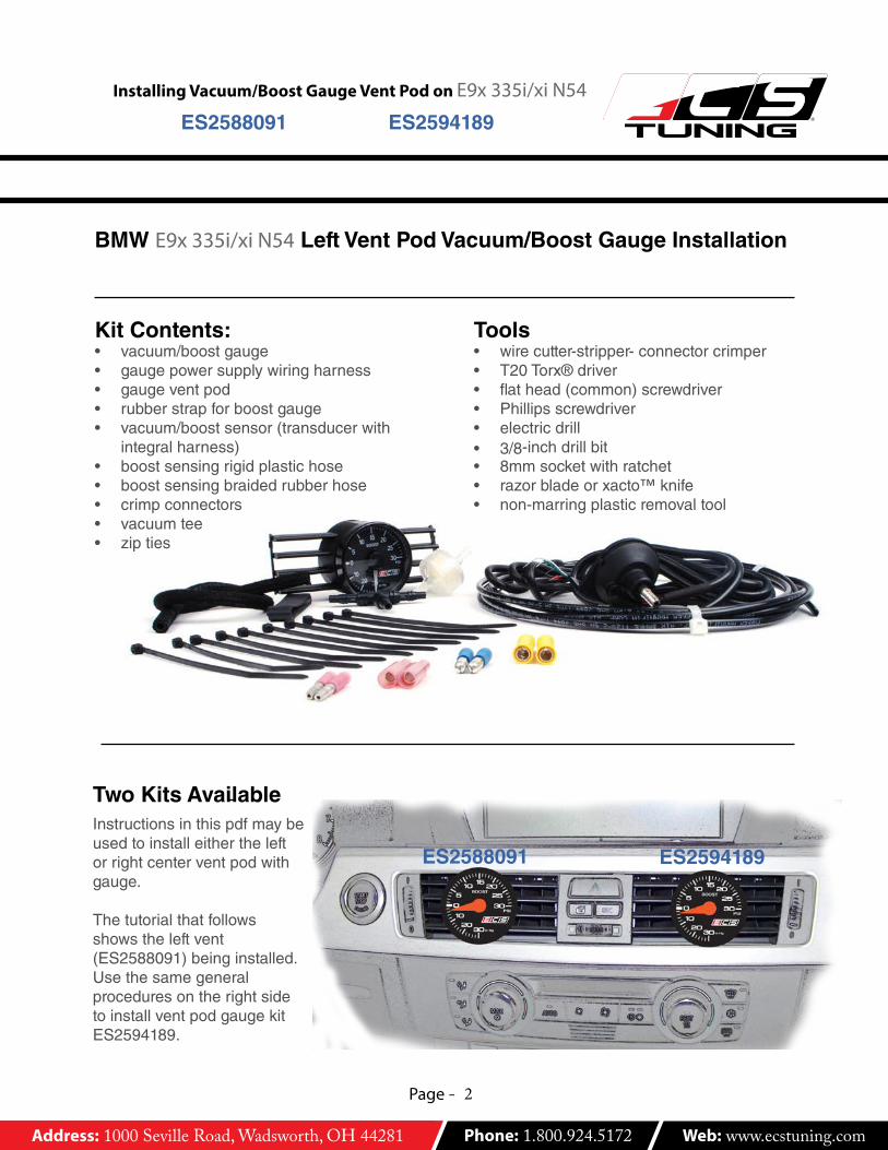
Kit Contents:• vacuum/boostgauge• gaugepowersupplywiringharness• gaugeventpod• rubberstrapforboostgauge• vacuum/boostsensor(transducerwith
integralharness)• boostsensingrigidplastichose• boostsensingbraidedrubberhose• crimpconnectors• vacuumtee• zipties
Tools• wirecutter-stripper-connectorcrimper• T20Torx®driver• flathead(common)screwdriver• Phillipsscrewdriver• electricdrill• 3/8-inchdrillbit• 8mmsocketwithratchet• razorbladeorxacto™knife• non-marringplasticremovaltool
BMW E9x 335i/xi N54 Left Vent Pod Vacuum/Boost Gauge Installation
Instructionsinthispdfmaybeusedtoinstalleithertheleftorrightcenterventpodwithgauge.
Thetutorialthatfollowsshowstheleftvent(ES2588091)beinginstalled.UsethesamegeneralproceduresontherightsidetoinstallventpodgaugekitES2594189.
Two Kits Available
ES2588091 ES2594189

Address: 1000 Seville Road, Wadsworth, OH 44281 Phone: 1.800.924.5172 Web: www.ecstuning.com
Page - 3
Installing Vacuum/Boost Gauge Vent Pod on E9x 335i/xi N54RES2588091 ES2594189
This tutorial is broken into five sections:
1) Run the Vacuum Line-Showshowtoinstallthevacuumteeatthedivertervalvevacuumhose,howtoroutetherigidvacuumlinefromtheteethroughthefirewall,andhowtoconnectittotheVacuum/BoostSensingTransducer.
2) Disassemble the Dashboard and Console-Showshowtodisassemblethedashboardandroutethegaugepowerandtransducerharnessestotheventopening.
3) Make Wiring Connections-Showshowtosplicegaugeandcarharnesswiring.
4) Reassemble Lower Console Components-Showshowtodisassemblethedashboardvents,installtheVentPodandBoostGauge,andconnectthewiringharnesses.
5) Installing and Connecting the Vent Pod and Gauge-Showshowtoinstall,connect,andtestthegauge.
Section 1 - Run the Vacuum Line
vacuum tee
moisture�lter
vacuum hose to diverter valve
boost sensing transducer
wire harnessto boost gauge
enginecompartment dashboard
rubberbraided hose
Vacuum Hose RoutingBoost Gauge
Inside the car:Removethescrewsatthefrontedgeoftheunderdashpanel.
Dropthelefthandsideunder-dashpanel.Makeasmallholeintherubberfirewallrubbersealabovethedeadpedalarea.Pushtherigidplasticlinethroughthegrommetintotheenginecompartment.
Use this schematic for reference to identify general components and locations as you route the vacuum hose and make connections.

Address: 1000 Seville Road, Wadsworth, OH 44281 Phone: 1.800.924.5172 Web: www.ecstuning.com
Page - 4
Installing Vacuum/Boost Gauge Vent Pod on E9x 335i/xi N54RES2588091 ES2594189
vacuum tee
moisture�lter
vacuum hose to diverter valve
boost sensing transducer
wire harnessto boost gauge
enginecompartment dashboard
rubberbraided hose
Vacuum Hose RoutingBoost Gauge
Inside the car:Mountthevacuumsensingtransducerinasafelocationunderthedash.
Connectthesensortothevacuumlineusingthediagramonthispageforgeneralreference.
Besuretoinstallthemoisturefilter.
Section 1 - Run the Vacuum Line
Under the hood:Installthevacuumteefromthekitinthevacuumsupplyhosetothedivertervalve.Useashortlengthofbraidedhosetoconnecttherigidhosetothevacuumtee.
Securealllineswithzipties.
Address: 1000 Seville Road, Wadsworth, OH 44281 Phone: 1.800.924.5172 Web: www.ecstuning.com
Page - 5
Installing Vacuum/Boost Gauge Vent Pod on E9x 335i/xi N54RES2588091 ES2594189
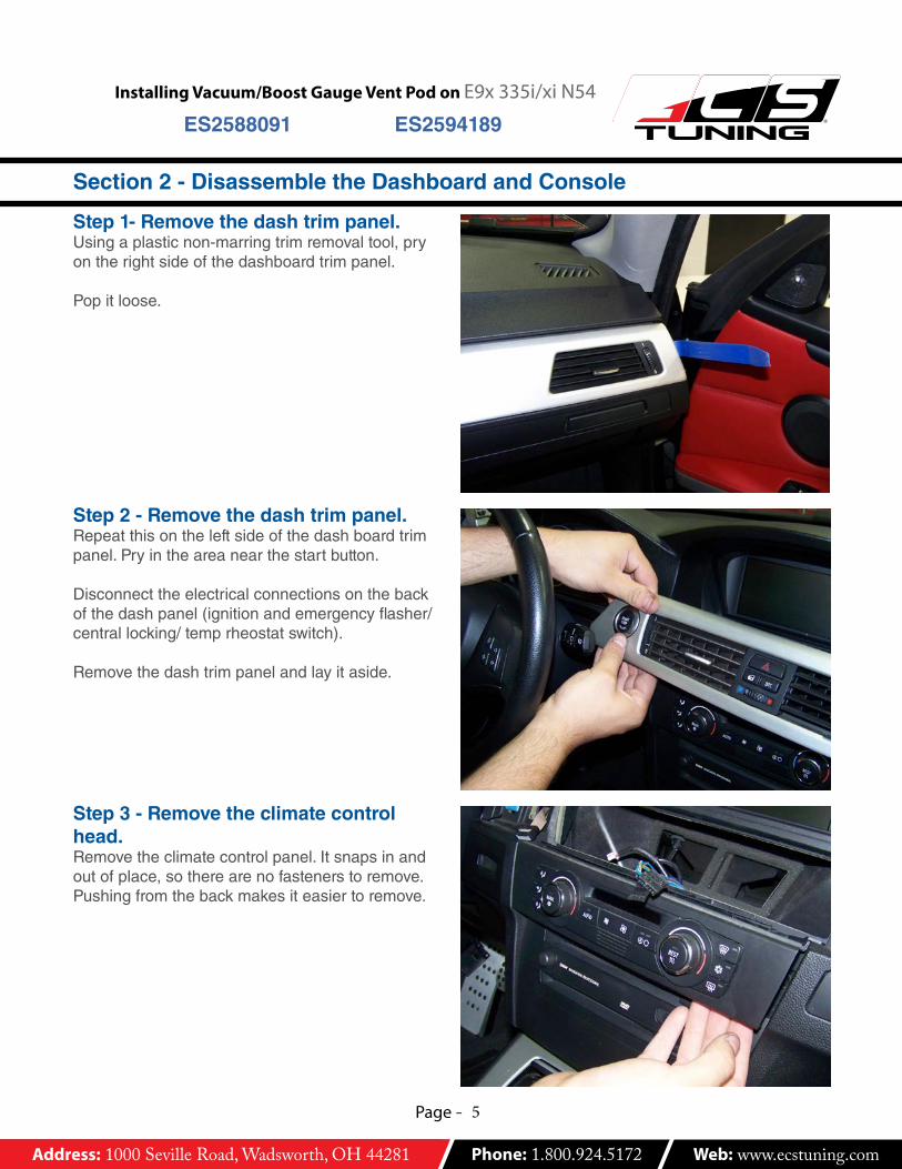
Step 1- Remove the dash trim panel.Usingaplasticnon-marringtrimremovaltool,pryontherightsideofthedashboardtrimpanel.
Popitloose.
Step 2 - Remove the dash trim panel.Repeatthisontheleftsideofthedashboardtrimpanel.Pryintheareanearthestartbutton.
Disconnecttheelectricalconnectionsonthebackofthedashpanel(ignitionandemergencyflasher/centrallocking/temprheostatswitch).
Removethedashtrimpanelandlayitaside.
Section 2 - Disassemble the Dashboard and Console
Step 3 - Remove the climate control head.Removetheclimatecontrolpanel.Itsnapsinandoutofplace,sotherearenofastenerstoremove.Pushingfromthebackmakesiteasiertoremove.

Address: 1000 Seville Road, Wadsworth, OH 44281 Phone: 1.800.924.5172 Web: www.ecstuning.com
Page - 6
Installing Vacuum/Boost Gauge Vent Pod on E9x 335i/xi N54RES2588091 ES2594189
Section 2 - Disassemble the Dashboard and Console
Step 4 - Unplug the climate control head.Afterremovingtheclimatecontrolheadfromthedash,disconnectthetwoelectricalconnectors,oneblackandonewhite.
Eachconnectorisheldinplacebyalockinglever.Pushtoreleasethelockingtabandrotatetheleversdownwardtounplugthetwoelectricalconnectors.
Laytheclimatecontrolheadaside.
Step 5 - Pry off the radio face.Useanon-marringtrimremovaltooltopryofftheradiotrimfascia.Layitaside.
Step 6 - Unscrew the radio.RemovethefourTorxheadradioscrews.
Address: 1000 Seville Road, Wadsworth, OH 44281 Phone: 1.800.924.5172 Web: www.ecstuning.com
Page - 7
Installing Vacuum/Boost Gauge Vent Pod on E9x 335i/xi N54RES2588091 ES2594189
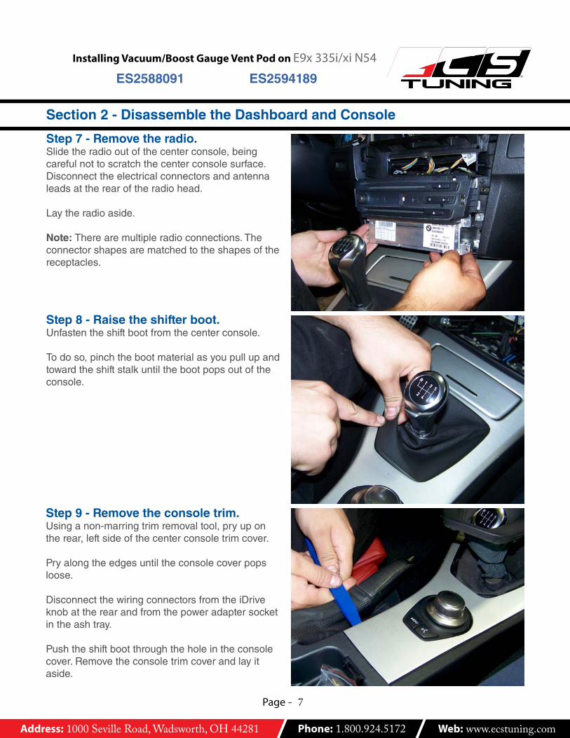
Step 7 - Remove the radio.Slidetheradiooutofthecenterconsole,beingcarefulnottoscratchthecenterconsolesurface.Disconnecttheelectricalconnectorsandantennaleadsattherearoftheradiohead.
Laytheradioaside.
Note: Therearemultipleradioconnections.Theconnectorshapesarematchedtotheshapesofthereceptacles.
Step 8 - Raise the shifter boot.Unfastentheshiftbootfromthecenterconsole.
Todoso,pinchthebootmaterialasyoupullupandtowardtheshiftstalkuntilthebootpopsoutoftheconsole.
Step 9 - Remove the console trim.Usinganon-marringtrimremovaltool,pryupontherear,leftsideofthecenterconsoletrimcover.
Pryalongtheedgesuntiltheconsolecoverpopsloose.
DisconnectthewiringconnectorsfromtheiDriveknobattherearandfromthepoweradaptersocketintheashtray.
Pushtheshiftbootthroughtheholeintheconsolecover.Removetheconsoletrimcoverandlayitaside.
Section 2 - Disassemble the Dashboard and Console

Address: 1000 Seville Road, Wadsworth, OH 44281 Phone: 1.800.924.5172 Web: www.ecstuning.com
Page - 8
Installing Vacuum/Boost Gauge Vent Pod on E9x 335i/xi N54RES2588091 ES2594189
1
2
3
4
wire
cutterinsulcrim
per
non insulw
ire stripp
er
mm
mm
6.04.02.51.51.00.75
4-62.51.5
Weprefersolderingelectricalconnectionsandthenprotectingthemwithheatshrinkableinsulation.
Forthosewhodonothaveaccesstosoldering,eachkitincludescrimp-styleelectricalconnectorsinthreesizes,identifiedbycolor.Thosewhoarefamiliarwiththeiruse,orwhointendtosolder,mayproceedtothenextpage,whereaschematicidentifiesharnessconnectionsandwirecolors.
Ifyouareunfamiliarwithusingcrimpconnectors,pleasereviewtheinformationonthispage.
Using crimp connectors
1)Cuttheheadlightharnesswireyouwanttotapinto.
Removeenoughinsulationfrombothlengthsofwiretoexposeashortlengthofwire(about3/8-inch).
2)Insertthetwolengthsofbaredwireintothefemalebulletconnector.Insertthecorrectmatchingwirefromthegaugeharnessintothemalebulletconnector.(Seenextpageforconnectorcolorsandlocations.)
3)Usingacrimpingtool,crimptheconnectorendsenoughtosqueezethebarewiresecurely.Donotover-crimp,oryoumaydamagetheinsulatingcollar.
4)Plugthetwoendstogether.Makesuretheyarefullyengaged.
Note: Useasuitablewirestripperthatwillremovetheinsulationwithoutcuttingawaywirestrands.
Useacrimpingtoolofthecorrectsize,notsidecuttersorotherpliersthatmaydamagetheinsulationontheconnectors.
Repeatthisprocessontheremainingwiresattheharnesses.
Section 3 - Make Wiring Connections
Address: 1000 Seville Road, Wadsworth, OH 44281 Phone: 1.800.924.5172 Web: www.ecstuning.com
Page - 9
Installing Vacuum/Boost Gauge Vent Pod on E9x 335i/xi N54RES2588091 ES2594189
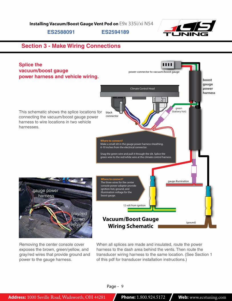
Splice the vacuum/boost gauge power harness and vehicle wiring.
Thisschematicshowsthesplicelocationsforconnectingthevacuum/boostgaugepowerharnesstowirelocationsintwovehicleharnesses.
boost gaugepower harness
green (battery hot)
12 volt from ignition
gauge illuminationWhere to connect?The three wires for the center console power adapter provideignition-hot, ground, and illumination voltage for the boost gauge.
Where to connect?Make a small slit in the gauge power harness sheathing, 6-10 inches from the electrical connector.
Snag the green wire and pull it through the slit. Splice the green wire to the red/white wire at the climate control harness.
blackconnector
Vacuum/Boost GaugeWiring Schematic
(ground)
power connector to vacuum/boost gauge
Whenallsplicesaremadeandinsulated,routethepowerharnesstothedashareabehindthevents.Thenroutethetransducerwiringharnesstothesamelocation.(SeeSection1ofthispdffortransducerinstallationinstructions.)
Removingthecenterconsolecoverexposesthebrown,green/yellow,andgray/redwiresthatprovidegroundandpowertothegaugeharness.
Section 3 - Make Wiring Connections

Address: 1000 Seville Road, Wadsworth, OH 44281 Phone: 1.800.924.5172 Web: www.ecstuning.com
Page - 10
Installing Vacuum/Boost Gauge Vent Pod on E9x 335i/xi N54RES2588091 ES2594189
Section 4 - Reassemble Console Components
Re-assembling the DashBeginre-assemblingtheconsoleanddash.
1)Reconnectthecenterconsolewiring:iDriveknobandpoweroutlet.
2)Reinstalltheradioandreplacetheradiofaceplate.
3)Reinstalltheclimatecontrolheadinthedash.
Beforeyoustartreassemblingthedashmakesureyouhaveroutedthegaugepowerharnessandtransducerharnesstotheventopeninginthedashboard(arrows).
centerconsoletrimcover
radiofaceplate
boostgaugeharnesses
climatecontrolhead
Wearenowreadytoassemblethegaugeandventpodandcompleteourinstallation.
RecapAtthispointwehave:• Installedthetransducerand
vacuumhoses.• Splicedthegaugepower
harnessconnections.• Routedthegaugepower
harnessandtransducerharnesstothedashboardventopening.

Address: 1000 Seville Road, Wadsworth, OH 44281 Phone: 1.800.924.5172 Web: www.ecstuning.com
Page - 11
Installing Vacuum/Boost Gauge Vent Pod on E9x 335i/xi N54RES2588091 ES2594189
CAUTIONInstructionsshownarefortheleftvent.UsethesamegeneralproceduresontherightsidecenterventifyouhavekitES2594189(rightcentervent).Seepage2.
Step 1 - Remove the Vent HousingUnboltthecenterventassemblyfromthedash-boardtrimpanelremovedearlier.Removethetwo8mmnutsoneithersideofthevent.
Step 3 - Remove the Front CoverRemovetheventassemblyfronttrimpanel.
Startbydisconnectingtheflapperdoorlinkagearmsonthesidesoftheventhousing(seenextphotofordetail).
Thenpushdownonthereleasetabsholdingthetrimtothehousingtoreleasethem.Arrowshigh-lightthetabslocatedonthetopofthehousing;therearetabsonthebottom,aswell.
Separatetheventhousingfromthefrontcover.
Step 2 - Remove the Vent HousingPryonthemoldedplasticattachmentsnapclipsconnectingtheventhousingtothedashtrimpanel.
Whentheclipsarereleased,pulltheventassemblyawayfromtherearofthedashboardtrimpanel.
Section 5 - Installing and Connecting the Vent Pod and Gauge
Address: 1000 Seville Road, Wadsworth, OH 44281 Phone: 1.800.924.5172 Web: www.ecstuning.com
Page - 12
Installing Vacuum/Boost Gauge Vent Pod on E9x 335i/xi N54RES2588091 ES2594189
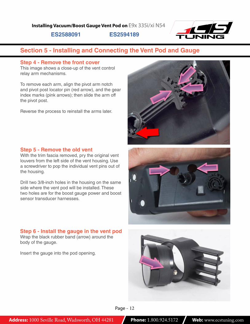
Step 6 - Install the gauge in the vent podWraptheblackrubberband(arrow)aroundthebodyofthegauge.
Insertthegaugeintothepodopening.
Step 5 - Remove the old ventWiththetrimfasciaremoved,prytheoriginalventlouversfromtheleftsideoftheventhousing.Useascrewdrivertopoptheindividualventpinsoutofthehousing.
Drilltwo3/8-inchholesinthehousingonthesamesidewheretheventpodwillbeinstalled.Thesetwoholesarefortheboostgaugepowerandboostsensortransducerharnesses.
Step 4 - Remove the front coverThisimageshowsaclose-upoftheventcontrolrelayarmmechanisms.
Toremoveeacharm,alignthepivotarmnotchandpivotpostlocatorpin(redarrow),andthegearindexmarks(pinkarrows);thenslidethearmoffthepivotpost.
Reversetheprocesstoreinstallthearmslater.
Section 5 - Installing and Connecting the Vent Pod and Gauge
Address: 1000 Seville Road, Wadsworth, OH 44281 Phone: 1.800.924.5172 Web: www.ecstuning.com
Page - 13
Installing Vacuum/Boost Gauge Vent Pod on E9x 335i/xi N54RES2588091 ES2594189
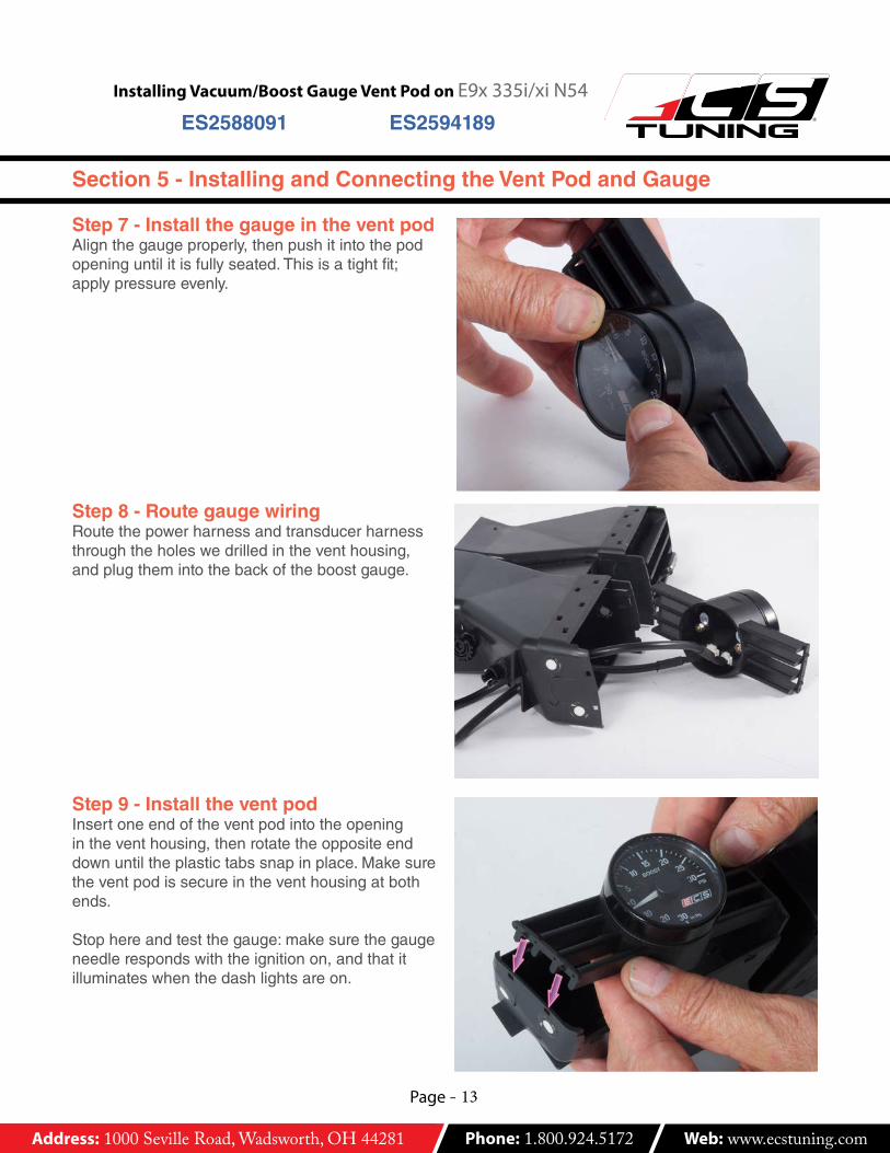
Step 7 - Install the gauge in the vent podAlignthegaugeproperly,thenpushitintothepodopeninguntilitisfullyseated.Thisisatightfit;applypressureevenly.
Step 8 - Route gauge wiringRoutethepowerharnessandtransducerharnessthroughtheholeswedrilledintheventhousing,andplugthemintothebackoftheboostgauge.
Step 9 - Install the vent pod Insertoneendoftheventpodintotheopeningintheventhousing,thenrotatetheoppositeenddownuntiltheplastictabssnapinplace.Makesuretheventpodissecureintheventhousingatbothends.
Stophereandtestthegauge:makesurethegaugeneedlerespondswiththeignitionon,andthatitilluminateswhenthedashlightsareon.
Section 5 - Installing and Connecting the Vent Pod and Gauge

Address: 1000 Seville Road, Wadsworth, OH 44281 Phone: 1.800.924.5172 Web: www.ecstuning.com
Page - 14
Installing Vacuum/Boost Gauge Vent Pod on E9x 335i/xi N54RES2588091 ES2594189
Step 10 - Reinstall the vent fasciaReinstallthefrontfasciatrimontheventassembly.Alignthetrimsectionevenlyontheventhousing.Pushthetwopiecestogetheruntilthetabsandmatingholesinbothsectionssnaptogetherse-curely.
Step 11 - Reconnect the vent armsReinstalltheventcontrolrelayarms,aligningcom-ponentsasshown.
Step 12 - Install dash assemblyBolttheventassemblywithgaugebackontothedashboardtrimpanel.(Reversesteps1and2inthissection.)
Reconnectthewiringharnessconnectorsattheignitionswitchandfour-wayflasher/doorlock/temprheostatswitch.Thenreinstallthedashtrimpanel.
Reinstalltheunder-dashtrimpanel.
Section 5 - Installing and Connecting the Vent Pod and Gauge
Address: 1000 Seville Road, Wadsworth, OH 44281 Phone: 1.800.924.5172 Web: www.ecstuning.com
Page - 15
Installing Vacuum/Boost Gauge Vent Pod on E9x 335i/xi N54RES2588091 ES2594189
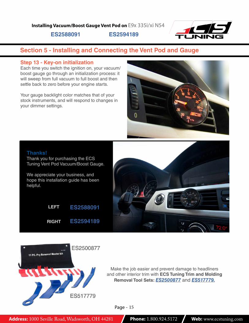
Step 13 - Key-on initializationEachtimeyouswitchtheignitionon,yourvacuum/boostgaugegothroughaninitializationprocess:itwillsweepfromfullvacuumtofullboostandthensettlebacktozerobeforeyourenginestarts.
Yourgaugebacklightcolormatchesthatofyourstockinstruments,andwillrespondtochangesinyourdimmersettings.
MakethejobeasierandpreventdamagetoheadlinersandotherinteriortrimwithECS Tuning Trim and Molding
Removal Tool Sets: ES2500877 and ES517779.
Section 5 - Installing and Connecting the Vent Pod and Gauge
Thanks!ThankyouforpurchasingtheECSTuningVentPodVacuum/BoostGauge.
Weappreciateyourbusiness,andhopethisinstallationguidehasbeenhelpful.
ES2588091
ES2594189
LEFT
RIGHT