
For Beginners AMSAT’s Venerable OSCAR-7 I in the ...amsat.org/wordpress/xtra/Getting Started...
2
4 The AMSAT Journal September/October 2011 www.amsat.org For Beginners AMSAT’s Venerable OSCAR-7 by Keith Baker, KB1SF / VA3KSF, [email protected] (Portions of this article previously appeared as “Spotlight on AMSAT-OSCAR 7” in the November, 2011 edition of Monitoring Times Magazine) I n previous columns I’ve discussed how those interested in receiving (and if properly licensed) actually working through our growing fleet of Amateur Radio satellites could do so with just modest radio equipment. In this edition, I’ll turn the spotlight on one of our oldest satellites … one that’s been in orbit (and at least semi- operational) for going on 30 years now! Beginnings AMSAT-OSCAR 7 (AO-7) was launched November 15, 1974 by a Delta 2310 launcher from Vandenberg Air Force Base near Lompoc, California as a secondary payload along with ITOS-G (NOAA 4) and the Spanish INTASAT satellite. AO-7 was the second satellite in AMSAT’s so- Telemetry beacons on 10 m and 2 m as well as on 70 cm rounded out the satellite’s RF suite. Unfortunately, AO-7’s 2304.1 MHz experimental beacon was never activated due to international frequency allocation issues. Four antennas mounted at 90-degree intervals on the base and two experimental repeater systems provided store-and-forward capability for Morse and teletype messages as it orbited around the world. The Mode- B transponder was designed and built by Professor Dr. Karl Meinzer, DJ4ZC, and Werner Haas, DJ5KQ (SK). The Mode B transponder was the first such transponder using Dr. Meinzer’s “HELAPS” (High Efficient Linear Amplification by Parametric Synthesis) techniques … a technology that was painstakingly developed by Dr. Meinzer as part of his Ph.D. dissertation. HELAPS was very effectively used on a number of AMSAT’s subsequent satellites. The two transponders were operated alternately by means of a timer arrangement, but transponder selection and output power control could also be accomplished by ground command. Each of the transponders included a keyed telemetry beacon at the upper edge of the downlink passband to provide housekeeping data as well as a reference marker to assist amateurs in setting their uplink power level. The cross-band design of the two transponders were one of the first such arrangements that permitted amateurs to monitor their own downlink signals so as to help them compensate for changing path loss, transponder loading and Doppler shift. The Lost is Found AO-7 was operational for nearly 7 years until a supposed battery failure caused it to cease operation in mid-1981. Then on June 21, 2002, Pat Gowen, G3IOR, stumbled onto something he noted as “remarkable” when hunting for what he called “interlopers” on our 2 m amateur satellite band. During his search, he came across a beacon sending slow, 8 -10 wpm Morse code on 145.973 MHz that was also slowly drifting downward to 145.970 MHz before fading out completely. The beacon sounded VERY familiar to him, but, clearly, it was coming from none of the (then) current satellite fleet. And because of the Doppler shift, the signals were obviously coming from a satellite. But which one? The beacon peaked at S9 and at times it took on a rough quality, wobbling in frequency then coming back strong and quite stable again. To his surprise, Pat later learned that the satellite he had been listening to was none other than our old AO-7 that had somehow come back to life! Jan King, W3GEY, AO-7’s original Project Manager, later noted that the satellite had a very good set of solar panels and the first Battery Charge Regulator (BCR) AMSAT ever flew. It was also the first spacecraft AMSAT ever built that was capable of actually overcharging the battery. As expected, when the battery failed one or more of the individual battery cells eventually failed “short”. However, what AO-7’s experimenters hadn’t counted on was what would happen if any one of the failed cells lost its “short” and the battery circuit became “open”. Then, the entire power bus would become “unclamped” from ground and the all spacecraft loads (including the transponders) could then draw power from the highly efficient solar arrays. At that point, AO-7 Photo1: AMSAT’s satellites are often built in the basements and garages of its experimenters. Here Dick Daniels, W4PUG, solders components into one of AO-7’s electronic modules. (Courtesy: AMSAT) called “Phase II” satellite series (Phase II-B). That is, unlike their relatively short lifetime predecessor satellites that only carried beacon transmitters, AMSAT’s Phase II satellites carried Amateur Radio RF transponders aboard. When it was launched into a relatively circular, 1444 by 1459 km, 101.7 degree inclination orbit, the octahedral shaped (360 mm high and 424 mm in diameter) satellite weighed in at about 65 pounds. The antenna array consisted of a circularly polarized, canted turnstile VHF/UHF antenna system along with an HF dipole. Similar to its immediate predecessor (AMSAT-OSCAR 6), AO-7 was built by a multi-national (German, Canadian, United States and Australian) team of radio amateurs under the direction of AMSAT-North America. It carried both a non-inverting Mode A (Mode V/A) and an inverting Mode B (U/V) linear transponder. Photo 2: AO-7’s final assembly “Clean Room” consisted of stud lumber and plastic sheeting installed in the basement of Dick Daniel’s, W4PUJ, home in suburban Washington, DC. Despite such sparse assembly arrangements, AMSAT has never a satellite rejected by a launch agency because of contamination. (Courtesy: AMSAT) might have enough solar power to become a “daytime only” satellite. Indeed, this is precisely what has since happened and what has miraculously caused AO-7 to come back to life after so many years of being dormant. The only downside to this now “daytime only” satellite is that, every time sunlight hits the spacecraft and it powers up after exiting an eclipse, AO-7
Transcript of For Beginners AMSAT’s Venerable OSCAR-7 I in the ...amsat.org/wordpress/xtra/Getting Started...
4 The AMSAT Journal September/October 2011 www.amsat.org
For BeginnersAMSAT’s Venerable OSCAR-7
by Keith Baker, KB1SF / VA3KSF, [email protected](Portions of this article previously appeared as “Spotlight on AMSAT-OSCAR 7”
in the November, 2011 edition of Monitoring Times Magazine)
In previous columns I’ve discussed how those interested in receiving (and if properly licensed) actually working
through our growing fleet of Amateur Radio satellites could do so with just modest radio equipment. In this edition, I’ll turn the spotlight on one of our oldest satellites … one that’s been in orbit (and at least semi-operational) for going on 30 years now!BeginningsAMSAT-OSCAR 7 (AO-7) was launched November 15, 1974 by a Delta 2310 launcher from Vandenberg Air Force Base near Lompoc, California as a secondary payload along with ITOS-G (NOAA 4) and the Spanish INTASAT satellite. AO-7 was the second satellite in AMSAT’s so-
Telemetry beacons on 10 m and 2 m as well as on 70 cm rounded out the satellite’s RF suite. Unfortunately, AO-7’s 2304.1 MHz experimental beacon was never activated due to international frequency allocation issues.Four antennas mounted at 90-degree intervals on the base and two experimental repeater systems provided store-and-forward capability for Morse and teletype messages as it orbited around the world. The Mode-B transponder was designed and built by Professor Dr. Karl Meinzer, DJ4ZC, and Werner Haas, DJ5KQ (SK). The Mode B transponder was the first such transponder using Dr. Meinzer’s “HELAPS” (High Efficient Linear Amplification by Parametric Synthesis) techniques … a technology that was painstakingly developed by Dr. Meinzer as part of his Ph.D. dissertation. HELAPS was very effectively used on a number of AMSAT’s subsequent satellites.The two transponders were operated alternately by means of a timer arrangement, but transponder selection and output power control could also be accomplished by ground command. Each of the transponders included a keyed telemetry beacon at the upper edge of the downlink passband to provide housekeeping data as well as a reference marker to assist amateurs in setting their uplink power level. The cross-band design of the two transponders were one of the first such arrangements that permitted amateurs to monitor their own downlink signals so as to help them compensate for changing path loss, transponder loading and Doppler shift.The Lost is FoundAO-7 was operational for nearly 7 years until a supposed battery failure caused it to cease operation in mid-1981. Then on June 21, 2002, Pat Gowen, G3IOR, stumbled onto something he noted as “remarkable” when hunting for what he called “interlopers” on our 2 m amateur satellite band. During his search, he came across a beacon sending slow, 8 -10 wpm Morse code on 145.973 MHz that was also slowly drifting downward to 145.970 MHz before fading out completely. The beacon sounded VERY familiar to him, but, clearly, it was coming from none of the (then) current satellite fleet. And because of the Doppler shift, the signals were obviously
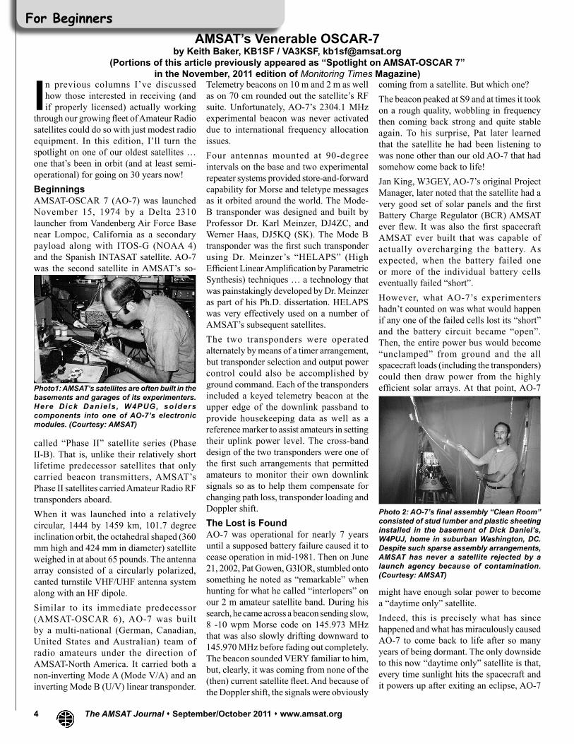
coming from a satellite. But which one?The beacon peaked at S9 and at times it took on a rough quality, wobbling in frequency then coming back strong and quite stable again. To his surprise, Pat later learned that the satellite he had been listening to was none other than our old AO-7 that had somehow come back to life!Jan King, W3GEY, AO-7’s original Project Manager, later noted that the satellite had a very good set of solar panels and the first Battery Charge Regulator (BCR) AMSAT ever flew. It was also the first spacecraft AMSAT ever built that was capable of actually overcharging the battery. As expected, when the battery failed one or more of the individual battery cells eventually failed “short”.However, what AO-7’s experimenters hadn’t counted on was what would happen if any one of the failed cells lost its “short” and the battery circuit became “open”. Then, the entire power bus would become “unclamped” from ground and the all spacecraft loads (including the transponders) could then draw power from the highly efficient solar arrays. At that point, AO-7 Photo1: AMSAT’s satellites are often built in the
basements and garages of its experimenters. Here Dick Danie ls , W4PUG, solders components into one of AO-7’s electronic modules. (Courtesy: AMSAT)
called “Phase II” satellite series (Phase II-B). That is, unlike their relatively short lifetime predecessor satellites that only carried beacon transmitters, AMSAT’s Phase II satellites carried Amateur Radio RF transponders aboard.When it was launched into a relatively circular, 1444 by 1459 km, 101.7 degree inclination orbit, the octahedral shaped (360 mm high and 424 mm in diameter) satellite weighed in at about 65 pounds. The antenna array consisted of a circularly polarized, canted turnstile VHF/UHF antenna system along with an HF dipole.Similar to its immediate predecessor (AMSAT-OSCAR 6), AO-7 was built by a multi-national (German, Canadian, United States and Australian) team of radio amateurs under the direction of AMSAT-North America. It carried both a non-inverting Mode A (Mode V/A) and an inverting Mode B (U/V) linear transponder.
Photo 2: AO-7’s final assembly “Clean Room” consisted of stud lumber and plastic sheeting installed in the basement of Dick Daniel’s, W4PUJ, home in suburban Washington, DC. Despite such sparse assembly arrangements, AMSAT has never a satellite rejected by a launch agency because of contamination. (Courtesy: AMSAT)
might have enough solar power to become a “daytime only” satellite.Indeed, this is precisely what has since happened and what has miraculously caused AO-7 to come back to life after so many years of being dormant. The only downside to this now “daytime only” satellite is that, every time sunlight hits the spacecraft and it powers up after exiting an eclipse, AO-7

The AMSAT Journal September/October 2011 www.amsat.org 5
comes up randomly in either Mode V/A (the old Mode A) or Mode U/V (the old Mode B).Current StatusSubsequent analysis has revealed that, even after almost 30 years in orbit (and with
modest satellite antenna arrays.However, it takes a bit of patience to determine which mode the satellite is in when it first pops over the horizon. I do this by first setting my downlink frequency in the middle of either passband (at, say 29.450 MHz or 145.950 MHz) and then send a few widely-spaced CW “dits” on the uplink while tuning the frequency of my uplink signal around. Once I hear my own “dits” coming back to me on the downlink, I immediately know which mode the satellite is in, and I then start looking for a contact.Operating TipsBecause of its relatively high power (2 - 8 watt) downlink transmitters, you should be able to hear very weak signals from AO-7 without needing a lot of uplink power. Remember, this satellite was never intended to be an FM bird! Indeed, I’ve successfully worked through AO-7 with 5 watts or less to my eggbeater antennas. You may need to increase power if the satellite is at a distance, but be sure to reduce power as the satellite approaches.Unfortunately, AO-7’s mode B uplink is also in the middle of the informal, 70 cm, so-called “weak signal” terrestrial band that was established after AO-7 first went silent. Excessive uplink power may interfere with other services in that band, and may be considered by some to be a spurious, out of band emission.Also, if you hear your downlink signal start to rapidly change frequency (indicated by a “warbling” sound) this means you are putting too much power into the bird. Reduce power and the situation should correct itself. What’s more, as the strongest signals are in the middle of the passband, you will therefore need less power to hear your downlink there. Remember, too, that, voice signals strain the power system on AO-7 the least. So, if you are using CW, please be extra vigilant about the amount of uplink power you are using. Hopefully, with reasonable care from all of us, AO-7 has many years of “semi-operational” life still left in it.Wrap UpThat’s all for this time. In future columns, I’ll once again focus on another series of Amateur Radio satellites now in orbit and I’ll bring you up to date on other happenings in this fascinating aspect of our radio hobby. See you then!
Photo 3: Members of the AO-7 project team pose with the fruits of their labor. From left are Dick Daniels, W4PUJ; Jan King, W3GEY; “hired hand” Marie Marr and AMSAT Founding President Perry Klein, W3PK. (Courtesy: AMSAT)
Photo 4: Jan King, W3GEY, prepares the AO-7 satellite for vibration testing. (Courtesy: AMSAT)
the notable exception of the now “open” battery), AO-7 remains in surprisingly good shape. The solar arrays, the BCR, the Instrumentation Switching Regulator, along with the Mode B and Mode A transponders appear to all be working beautifully. What’s more, the Morse code telemetry encoder and voltage reference circuitry and other onboard electronics are all still providing useful data to AO-7’s ground handlers. And what a testament AO-7 has since become for a satellite that was built (quite literally) by a group of “amateurs” in their basements and garages and launched into Earth orbit almost 30 years ago!When and Where to ListenSince it sprang back to life, AO-7 has once again become one of AMSAT’s most popular linear (analog) satellites. Indeed, when AO-7 is in full sunlight, it provides surprisingly strong (albeit somewhat “chirpy”) downlink signals … even using
Photo 5: AO-7 is shown here mated to the upper stage of its Delta rocket. AO-7 is shown at the bottom right, next to the much larger main payload. (Courtesy: AMSAT)
Photo 6: AO-7 was successfully launched on November 15, 1974 by a Delta 2310 launcher from Vandenberg Air Force Base near Lompoc, California (Courtesy: NASA)
AO-7 FREQUENCY AND MODE DATA
MODE UPLINK (MHz) DOWNLINK (MHz) BEACONS (MHz)
V/A (Mode A) 145.850 - 145.950 29.400 - 29.500 29.502
U/V (Mode B) 432.125 - 432.175 145.975 - 145.925 145.975
435.100
Photo 7: An artist’s concept of how AO-7 might appear in orbit today. (Courtesy: AMSAT)