foils.orgfoils.org/wp-content/uploads/2017/11/0109-CONFORM-NATO-SES-ASW-Corvette-App.pdfThe...
527
Transcript of foils.orgfoils.org/wp-content/uploads/2017/11/0109-CONFORM-NATO-SES-ASW-Corvette-App.pdfThe...

_-—. ,.. , ... .. .
‘-.-/
S!JRFACESHIP CONTINUI$:GCOKCEPTFORMULATION (CONFORM) FY 86FEASIBILITY DESIGN STUDY .
FINAL REPORT
NATO SES ASW COR’JETTE
VOLUME II-- APPENCIICES .
..
MAY 1986
t{AVSEATechnical Note No.”041-501-TN-0C25
---’
. . .
.
.
.
“e

TABLE OF CONTENTS
d APPENDIX
B
c
II
E.1
E.2
E.3
E.4
E.5
E.6
E.7
E.8
E.9
F
G
H
I
TITLE
Propeller Design
Structural Design
Comparison of Structural Scantlings
Criticality Analysis
Drainage System
HVAC System
Fresh Water System
Fuel System
~ Compressed Air/Nitrogen System
Fire Extinguishing System
Hydraulic System
Refrigeration System
Weight Estimate
Area/Volume Summary
1 Bell-Textron Report (Propeller Design)
Su12er-Escher Wyss Report (Propeller Design)
FRG Structural Drawings

d
APPENDIX B
PROPELLER DESIGN
.--’
—
B.1 VENTILATED PROPELLER
“d
The ventilated propellers studied are controllable pitch partially
submerged “types. Performance data for the propellers is given in
Section 16.
The propeller blades are made from forgings machined all over to achieve
accurate profiles and sections. Candidate blade materials
steel. nicket based superalloy and nickel-aluminum bronze.
Each blade is replaceable externally via a bolted joint
are stainless
with no other
disturbance of the propeller or
propeller blades can be changed
section is a wedge with an annex
d’
,
pitch change mechanism required. The
while the ship is afloat. The blade
section as shown in Figure B.1. This
blade shape and section is similar to that used successfully on the
SES-1OOB.
The propellers derived from this study have diameters of 3 and 4 meters
and a hub to tip ratio of 0.4. The hub is an approximately cylindrical
body made from corrosion resistant material which contains the pitch
change mechanism. Attached to the after-end of the hub is a fairing.
The propeller is mounted behind the sidehull so that 25 or 50 percent of
its disc area is masked by the sidehull transom. From the propeller, the
drive shaft is installed at an inclined angle up and foward.
Immediately adjacent to the propeller hub is the thrust bearing module.
B-1
m.F.
(
‘i—”~ x
SIDE VIEW
Hub
t
I \Hub (0.4R)
II—.— -~ zi
PROJECTED VIEW
(.
Back
ReferenceLine
I
. ..—. .
\\-wFace
Annex
,
I--.EXPANDED VIEW

,
B.2‘d
Many
PITCH CHANGE KXHANISM AND CONTROLS
modern commercial and naval ships use controllable pitch propellers
to achieve operating economy and to suit the special
particular ship. Pitch change mechanisms and their
fully developed as a consequence.
requirements of the
controls have been
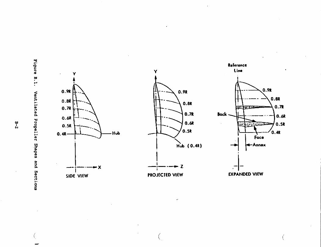
The Tacoma Boat/Escher Wyss type of’pitch change mechanism
shown in Figure B.2 is briefly described as follows.
Each propeller blade is bolted to a trunnion which carries
Each crank arm is linked to a seawomotor piston. Hydraulic
the piston via a double oil tube from an oil distribution
within the hull either on the end of the propeller shafting-/
amd control is
a crank arm.
oil is fed to
unit mounted
or around the
propeller shaft. The double oil tubes are nested inside the propeller
shaft. A control valve and feedback system is integral to the oil
distribution unit. In response to a pitch change signal, the control
valve directs pressurized oil to the semmmotor piston. As the piston
moves, and causes the propeller blades to rotate on their trunnions, a
feedback signal is transmitted back mechanically to the control valve
(via the double oil tube) so that when the input signal and propeller
blade pitch agree, the control valve spool is centered and no further
blade movement occurs. Pressurized oil is supplied from a tank having
main and standby electric pumps. The tank is connected to a head oil
tank so that when the system is unpressurized there is sufficient head in
the propeller pitch change mechanism and hub to prevent ingress of the
4 surrounding water. This mechanism plus the command transmitter, pitch
B-3 1
u
1.Propol!wPropel!crblade
B’.llsc Zeal
aoublesuppo’ted!):~dc !“un~IOflMlust, nq crankTr.;~n80n tlut~1lkCr:ss headwithdsublcsupportedadlustlng rodSewomotor piStOn
Pro~eilerhub
sewomotor cylinder
II. PropellerSh~lt:1pr~:ec:lnghoodfor
fs”onalle?shaftflange;:su~h,nqOfStemtube
seal~:Pre~el!crskaft*:CsAoling flanqe-j ~:uI:IC 011tube
III. 0;! DistributionUnit
Figure B.2.
o,I~,s!:.buttonshaft
0,1 dls!ributlcn baxkouslng!rn:e.mcdla!e shaftCantrol housing
Feedback system
2? Control valve
22 P, Jot valve
IV.HydraulicConkolSystem23Mainandstandby .
control011oumctWithelcctflcmotor
24 Suctiontank(yard”ssupply)
2S Head oiltank26 Oilfilter27Ottcooler:8 Handpumpfor
mec5an4calIock,ngdewce
~ MedtanlcalIoculng device,
V. RemoteControlandPitchIndication~:Command transml:ter31 SlaVeJnlt32 Mechanical cannec!ion
~ysrd”s S@Plyl
~: ?l!& setter3J +~ndwl=eei for!ocal
eme~ge-:ycantrol
~j hfechantcal pI!c!lladlcatlon
:6 A:tual Pitch:ransmttter
37P,tchIndicator
Typical Pitch Change Mechanism and Controls
L’
J
B-4
indicator, and normal hydraulic system components comprise a reliable and
._/simple pitch change mechanism and controls. Provisions are made to allow
.
emergency local control in the event of hydraulic failure.
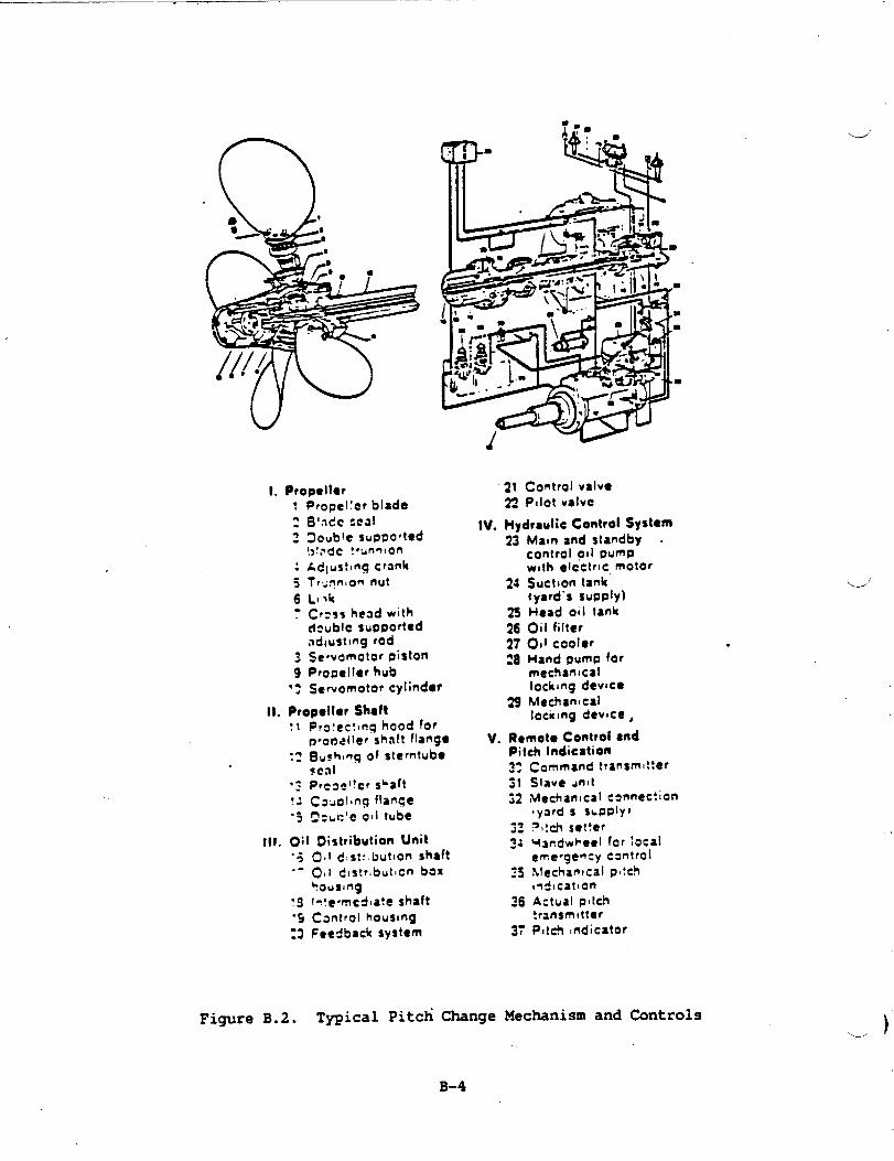
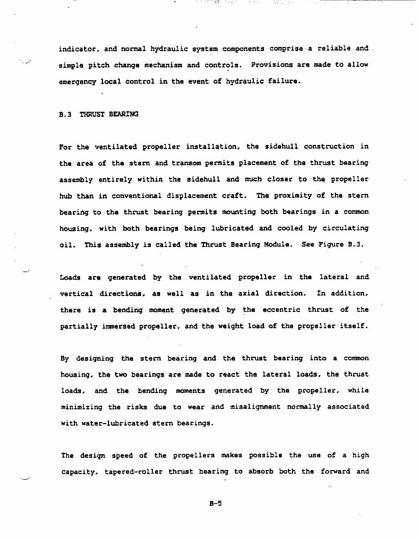
B.3 THRUST BEARING
For the ventilated propeller installation, the sidehull construction in
the area of the stern and transom permits placement of the thrust bearing
assembly entirely within the sidehull and much closer to the propeller
hub than in conventional displacement craft. The proximity of the stern
bearing to the thrust bearing permits mounting both bearings in a common
housing, with both bearings being lubricated and cooled by circulating
oil. This assembly is called the Thrust Bearing Module. See Figure B.3.
---”Loads are generated
vertical directions.
there is a bending
by the ventilated
as well as in the
moment generated by
propeller in the lateral and
axial direction. In addition,
the eccentric thrust of the “
partially inmersed propeller, and the weight load of the propeller itself.
By designing the stern bearing and the thrust bearing into a common
housing. the two bearings are made to react the lateral loads, the thrust
loads, and the bending moments generated by the propeller, while
minimizing the risks due to wear and misalignment normally associated
with water-lubricated stem bearings.
The design speed of the propellers makes possible the use of a high
capacity, tapered-roller thrust bearing to absorb both the forward and.-/
B-5

●
-6!5 ~“
.—-..
.—
.
J-
1
—-_-J7
..-J
I3 -..-,-7.-—.
.—-...-1
--- J.—.1
r_,...r—4 ‘7.....
M
.-e
,---—I.-
“w;
FigureB.3.
ThrustBearingModule

reverse thmst of the propeller, and a high-capacity cylindrical roller
-.--’ bearing to react the loads and moments due to the combined effects of
propeller weight, vertical thrust, lateral thrust, and offset axial
thrust. “
The radial bearing is located aft, closest to the propeller. to minimize
the propeller shaft bending moment.,
fo=ard end of the “housing to react
the lower radial loads that occur at
The thrust bearing is located at the
the axial thrust of the propeller and
this location in the drive line.
The propeller hub is flanged-bolted directly to the aft flange of the
thrust bearing module. The aft half of the gear coupling that connects
the propeller to the gearbox is flanged-bolted to the forward end of the
bearing module.
d
The thrust bearing module is foot-mounted in the horizontal plane that. .
contains the shaft centerline, to minimize the load on the hold-down
bolts from the axial thrust of the propeller. Since both bearings that
support the propeller are oil lubricated. rolling contact assemblies,
progressive wear and resulting misalignment that occur in-.
water-lubricated stern bearings are eliminated. This feature is of
particular importance when considering the complex loading into the
bearings and hull structure that occur with ventilated propellers, and
the compounded adverse effects -that wear in the stern bearing would
produce.
‘,d
This module incorporated one cylindrical roller bearing that accommodates
only radial loads, and a pair of taper~ roller bearings in a ‘TDI’
B-7

,
mounting, to accommodate axial thwt in either direction while providing
for slight angular misalignments resulting from shaft deflections. Allu
bearings are lubricated by circulating oil that is filtered and cooled by
the system that serves the propeller gearbox. Lube oil to the bearings
is supplied by a number of jets evenly spaced around one side of each
bearing annulus. The oil to the thrust bearings is fed by separate jets
on each side of the assembly, from where is
the space between the outer races, then to
to a sump; the oil is pumped from this sump
flows through the bearings to
the groove and a gravity drain
to the sump in the gearbox.
Horizontally split oil seals are
All parts in each seal assembly
installed at each end of the
may be inspected and replaced
disturbing the bearings or removing the module from its mounting.
Bearings are secured and clamped by hardened steel rings that are
to the proper axial fitup at assembly.
module.
without
. w’
shimmed
The bearing housing is nade from a steel wel&ent that is stress relieved
prior to final machining. The housing is bolted to the ship’s structure
at two flanges that extend radially outward from the housing, with the
bolting surface lying in the horizorital plane that contains the shaft
centerline. This construction minimizes eccentric loading of the module
housing as well as of the ship’s structure under the action of the
propeller thrust.
All exposed parts
corrosion.
of the bearing module are treated and coated to resist
J
B-8

B.4 DRI& -S AND COUPLINGS,“.-’
In order to reduce weight, forged tubular drive shafts are used to
transmit torque from the gearboxes to the propeller. Shaft weights are
reduced to about 50 percent of the weight of a solid shaft operating at
the same design stress. In the case of the propeller shafting, the
central hold is used to route the hydraulic oil feed tubes for the
controllable pitch propeller from the control unit. located on the
forward side of the gearbox, to the propeller hub outboard of the thrust
bearing module.
*
All shafts are machined from through-hardened alloy steel, and are
designed for combined stresses in bending and torsion that do not exceed
10,000 psi at the maximum load conditions. Exposed sections of shafting[d
are coated to resist
i
Torque through the
corrosion.
thwst bearing module is transmitted by means of
flanges splined, piloted. and bolted to the shaft ends. All splines are
registered by means of a long pilot on each side of the spline. In the
thrust bearing module the replaceable seal sleeves are clamped by the
bolting interface for the spline to minimize the number of loose pieces:
the seal sleeves serve also as the clamping rings for the inner races of
the radial and thrust bearings.
The size of the drive shafting in each configuration was determined by
the bore size of the thrust bearing required to react the propeller.
thrust load. An additional factor was the need for a hollow shaft ind

,
which to install the piping and control transfer mechanism for the
controllable pitch propeller.
The weight”of the drive shafting was determined by the outside diameter
and the design stress level. The shafting for these applications is
designed primarily to transmit the torque from the gearbox to the thrust
bearing mdule, with a very minimum of bending. The radial loads and
bending moments due to the ventilated propeller are reacted by the
bearings in the thrust bearing module (thrust block) at the transom. The
shaft bore size was determined on the basis of the allowable torsional
shear stress, which was set at a maximum
engine torque.
The shaft sizes for both propulsion plant
from these considerations, are tabulated in
value of 6000 psi at maximums
A preliminary survey of available
torques for both propulsion plant
J
configurations, as determined “
Figure B.3. u’
_ COUPLINGS
Because of the low propeller speeds in both configurations, the large
propeller shaft torques are beyond the range of most coasnercially
available flexible couplings. Flexible couplings are considered
necessary to accommodate misalignments, therud differential expansion
between the steel machinery and the aluminum sidehulls, and distortions
in the sidehulls due to conditions that include off-cushion and -
on-cushion operation under wide ranges of loading in various sea states.
couplings indicated that the propeller
configurations exceed the capacities of
J
B-10

.. —.“
commercially available disc and diaphragm couplings. Available
._.”grease~lubricated gear couplings manufactured by Zurn (Reference 6) were.
found to have torque capacities adequate not only for the present torque
loads, but for torque loads well in excess of present requirements. In
the torque ranges in which disc couplings are available, the weights of
the disc and gear couplings are comparable. Therefore, it is expected
that no weight penalties will develop when gear
the subject drive lines. From the layouts
developing the concepts for the thrust bearing
couplings are.applied to
made in the course of
modules, the proportions
of the
thrust
gear couplings are consistent with those of the shafting and the
bearing modules.
B.5 WAT= PERFORMANCE
.--’
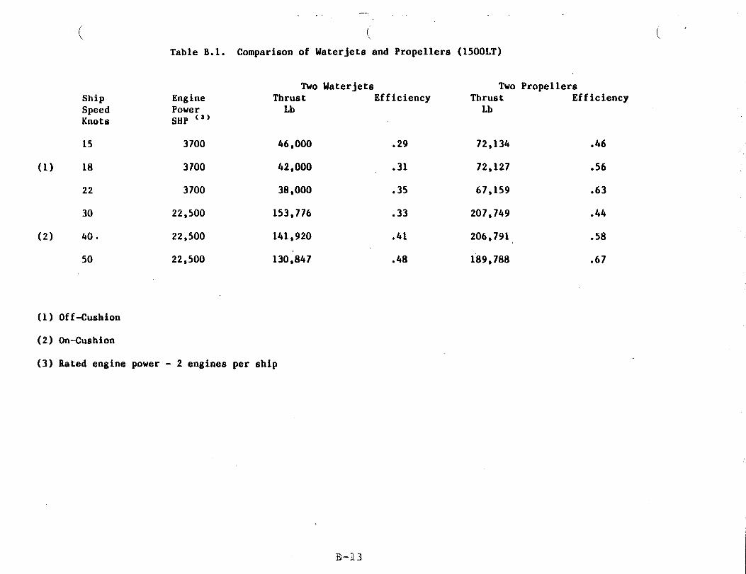
Conceptual waterjet installations were reviewed to provide comparative
inputs to the propeller selection process. Figure B.4 shows that, in
general, waterjet propulsory have a lower efficiency than propellers.
This reflects directly on range and speed performance. The conclusion is
confirmed by comparison of the ALRC PHM waterjet pumps and ventilated
propellers shown in Table B.1.
For low speeds, i.e., about 18 hots, the
waterjet propulsion were calculated using
SACM195V20RVR diesel engines. This is
thrustlefficiency values for
two PJ-24 pumps powered by
in accordance with current
practice for waterjet propelled ships whereby a separate cruise or low
speed propulsion mode is furnished by a separate system. Examples of“
these cmise systems include the PHM hydrofoil, the “American Enterprise”4
crew boat and “HMB Speedy”, a hydrofoil patrol ship very similar to the
B-n
*

“Jetfoil” hydrofoil ferry.
would drive the lift fans
the maint UK2500 engines.
For the NASW SES the cruise
in the cushion-borne tie when
waterjet diesel
vpropulsion is by
The values of thrust given in Table
waterjets would give approximately
when compared to two propellers
B.1 show tlpt for the NASW SES, two
5 knots less off-cushion top speed
and approximately 10 knots less
on-cushion top speed. These differences do not take into account the
weight differences of the two installations which are judged to
favor of the propeller
entrained water in the
would affect, primarily,
ship propulsion machinery largely because
inlet ducting and waterjet pump. This
range since less fuel could be carried.
be in
of the
weight
In view of these results, waterjets are eliminated early in the study~
phase.
B.6 FuLLY~ PROPELLER
A brief study of a fully submerged trans-cavitating propeller was sized
to verify its suitability as a backup to the baseline partially submerged..
ventilated propellers. The performance appears to be acceptable and
could be implemented if required.
~ PROPELLER PERFORMANCE
Submerged propellers were selected using cavitation tunnel data. This.
data contains the effect of blade area ratio, pitch angle and cavitationG}
B-12
—. . .
( (Table B.1. Comparison of Waterjets and Propellers (1500LT)
ShipSpeedKnots
15
(1) 18
22
30
(2) 40.
50
EnginePowerSHP ‘“
3700
3700
3700
22,500
22,500
22,500
Two WaterjetsThrust EfficiencyLb
46,000 .29
42,000 .31
38,000 ● 35
153,776 .33
141,920 .41
(1) Off-Cushion
(2) On-Cushion
(3) Rated engine power - 2 engines per ship
130,847 .48
Two PropellersThrust EfficiencyLb
72,134 .46
72,127 .56
67,159 .63
207,749 .44
206,791 .58
189,788 .67
IF-I-13
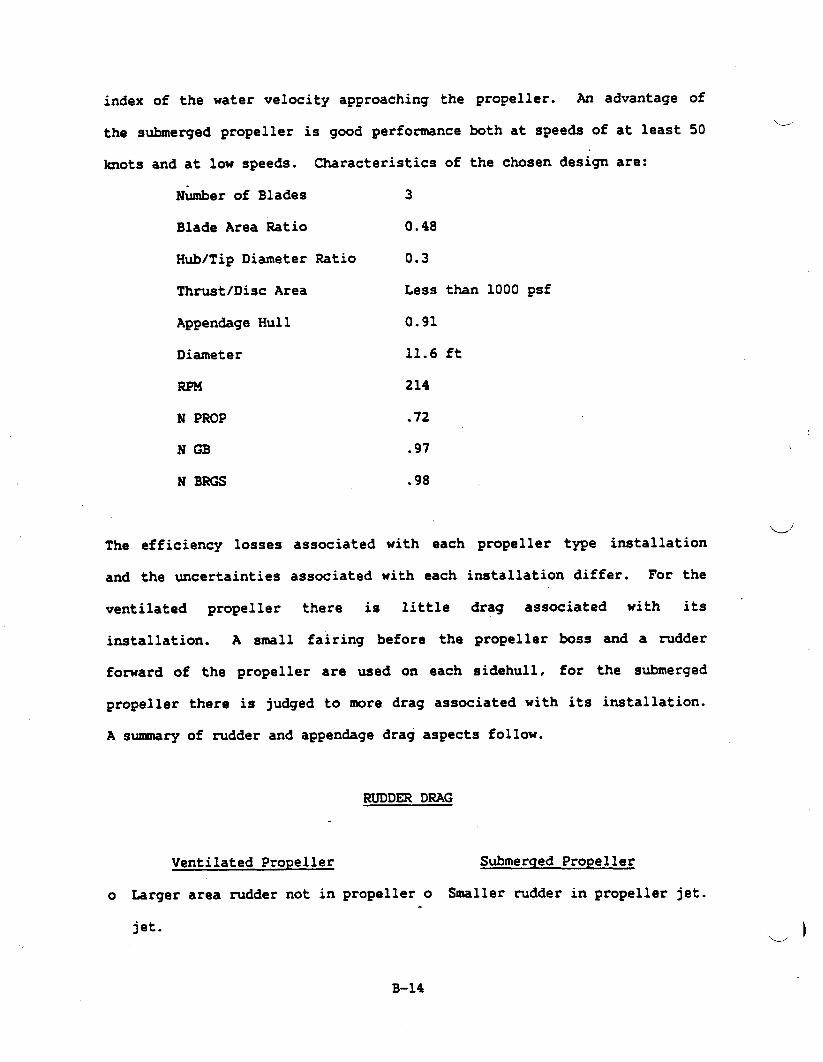
index of the water velocity approaching the
the submerged propeller is good performance
hots and at low speeds. Characteristics of
N&nber of Blades 3
Blade Area Ratio 0.48
Hub/Tip Diameter Ratio 0.3
propeller. An advantage
both at speeds of at least
the chosen design are:
of
\_50
Thrust/Disc Area Less than 1000 psf
Appendage Hull 0.91
Diameter 11.6 ft
214
N PROP .72
NGB .97
N BRGS .98
-.
The efficiency losses associated with each propeller type installation
and the uncertainties associated with each installation differ. For the
ventilated propeller there is little drag associated with its ‘
installation. A smell fairing before the propeller boss and a rudder
forward of the propeller are used on each sidehullt for the submerged
propeller there is judged to more drag associated with its installation.
A suxmary of rudder and appendage drag aspects follow.
RUDDER DRAG
Ventilated Propeller
o Larger area rudder not in
jet.
Submerged Propeller
propeller o Smaller rudder in propeller jet..
B-14
. .
J
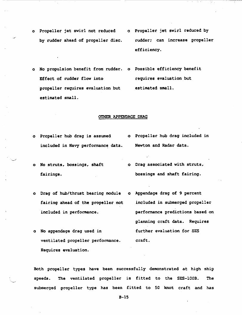
o Propeller jet swirl not reduced o Propeller jet swirl reduced by
by rudder ahead of propeller disc. rudder; can increase propeller
efficiency.
o No propulsion benefit from rudder. o Possible efficiency benefit
Effect of madder flow into requires evaluation but
propeller requires evaluation but estimated small.
estimated s-11.
OTHER APPENDAGE DRAG
o Propeller hub drag is assumed o
included in Navy performance
do No stm.ks, bossings, shaft
fairings.
&ta.
o
0 Drag of hub/thrust bearing module o
fairing ahead of the propeller not
included in performance.
o No appendage drag used in
ventilated propeller performance.
Requires evaluation.
Propeller hub drag included in
Newton and Radar data.
.’
Drag associated with struts,
bossings and shaft fairing.
Appendage drag of 9 percent
included in submerged propeller
performance predictions based on
plaming craft data. Requires
further evaluation for SES
craft.
Both propeller types have been successfully demonstrated at high ship
speeds. The ventilated~-
submerged propeller type
propeller is fitted to the SES-IOOB. The
has been fitted to 50 knot craft and has
B-15
performed well. At this time adequate performance for the NASW is
indicated using either propeller type based on available data.
B.7 WEIGHTS
Weight esti-tes for the lift and propulsion equipment have been made
based on manufacturer’s data for standard off-the-shelf machinery,
responses to requests for quotation where special equipment was involved
and on designs and calculations based on the installation layouts. Al1
components and subsystems have been sized in accordance with the
performance requirements. The total weight
and propulsion systems
each SWBS 3-digit group
is 238 long tons.
follow.
DIESEL R4GINES (SWBS 233)
Four engines in two sizes are used for
drives; these are the SAC24195V12RVR’S and
engine weights, including their respective
are from catalog information.
of the equipment for the lift
Descriptions of the items in
the propulsion and lift fan ,
two are SACM 195V20RVR’S. The
stan&rd accessories packages
TURBINES
An LM2500 gas turbine engine in production by the General Electric
Company is installed in each sidehull. The exhaust collectors are
included as part of the engine weights. The weights of the lube oil
systems external to the engine are included in SWBS item number 262.
‘u’
B-16

GEARING
..
There are six gearboxes in the lift and propulsion system; four are
modified versions of standard parallel-shaft increase and are used in the
lift system drives; the other two are special combination
parallel-shaft and planetary gearing and are used in the
system. Weight estimates for the lift fan gearboxes are based
designs of
propulsion
on catalog
data; the weights of the gearboxes for
preliminary design layouts developed by
lube system weights for all gearing are
the propeller driven are based on
the Cincinnati Gear Company. The
included in SWBS item number 262.
CLUTCHES AND COUPLINGS (SWBS 242)
The weight of equipment in this category comprises those components ,d
installed or mounted remotely from the engines and gearboxes. Included
in this group are the flexible couplings between the propeller gearboxes
and the propeller assemblies. and the overmanning clutches installed
between the gas turbines and the propeller gearboxes.
SHAl?ZINGAND SEALS (SWBS 243)
The weights in this category include only the shafting and seals that are
separate from equipment such as the engines. gearkxes, fans. etc.? and
involve primarily the lift fan and propeller shafting and the stem seals.
B-17
BEARINGS (W= 244 )
u
Included are the special bearing assemblies designed to support the
propellers”and the aft ends of the turbine engine shafts. The weights of
all other bearings are included in the weights of the equipment in which.
they are installed.
PROPELLERS AND CONTROLS (SWBS 245)
The
and
weights tabulated comprise those of the controllable pitch
the associated hydraulic actuators and controls, including
propellers
piping and
valves. The weights of the propeller shafting and thrust bearings are
listed under SWBS 243 and 244, respectively.
LIFT FANS (SWBS 248)
Six lift fans are installed, two forward and two
fans are the same size and capacitY. The
inter-connecting shafting, couplings, and the
installation.
COMBUSTION AIR SYST= (~S 251)
in each sidehull. All ‘
fan weights include
ductwork required for
This equipment comprises two sets of demisters and filters, one set per
sidehull, to condition the combustion air for the gas turbines. Included
are the weights of the acoustic treatment and the anti-ice equipment for
the duct walls.>}
B-18

.
Propulsion Control (SWBS 252).__-’
.
The propulsion control equipment comprises the controls and monitoring
equipment for the gas trubines and the diesel engines, but does not
include the controls for the controllable gas propellers, which are
included in SWBS item number 245.
Uptakes (SWBS 259)
The weights of the uptakes include the weights of the exhaust ducting for
the gas trubines and for the diesel engines..
Lube Oil Systems (SWBS 262)
d
The lube oil systems comprise the main pumps, auxiliary pumps, heat
exchangers, filters, valves, and piping for the gas turbines and the lift
fan and propulsion reduction gears. The
engines are included as part of the engine
item number 233.
lube systems for the diesel
accessories packages in SW’BS
Operating Fluids (SWBS 298)
The weights of the operating fluids include the lube oil and cooling
water for the turbines, diesel engines, and the lift fan and propulsion
gearboxes.
B.8:TECHNICAL RISKd
B-19

.
The following subsections are a discussion of the technical risk for the
prime movers, the propulsory. and the reduction gearing.“._.
B.8.1 PRIl& MOVERS
The ancillary system for the
art. The air inlet system,
by-pass provisions, anti-ice
prime movers are all within the state of the
a combination of ducting, demisters with
systems and noise suppression measures have
all been applied to modern ships in commercial and Navy service with
excellent results. The inlet system for the SES is a completed design
which was fully model tested for performance during the 3KSES Program.
All gas turbine and diesel powered craft and ships have similar air inlet
systems. Similarly, exhaust/uptake systems, usually comprised of gas
turbine and diesel connections, ducting, sound suppression material/itemsw
and weather closures, are well known, within the state of the art and
show good service.
DIES&L WINES — The MTU 16VS38TB82 and alternative engines are
representative of modern, reliable, high specific power, high speed
diesels being used in increasing numbers for all
world-wide. These engines are fully developed mgged units
economy at part and full load and are considered low risk.
applications
with superior
GAS TURBINES — The GE LM2500 gas turbine is a fully developed free
turbine unit currently in Navy inventory. Service experience includes
the DD 963, the FPG 7, the PHM and ships of foreign Navies. There is low
risk associated with its selection:
B-20

—-
REDUCTION GEAR — The reduction gear design is a low risk conservative,
state-of-the-artJ design furnished by the Cincinnati Gear Company. The
been compromised by s-11 size, weight or low cost
would reflect on reliability. Premium grade steels and
design has not
approaches.which
conservative stress levels combined with a rigid casing, generous bearing.
areas, high capacity lube supply and fully factored loadings give
confidence in the design. The reduction gear designs which are proposed
do not require developmental activity or unusual manufacturing techniques.
Comparable k-sewice reduction gears designed and manufactured by the
Cincinnati Gear Company include the parallel offset reduction gearhx for
the Boeing Jetfoil
American Enterprise
and the combined drop/epicyclic gearbox for the
craft.
u B.8.2 PROPULSORY
is considered to be the lowest risk. klany have been,
being used, for high speed naval craft such as the PC
are therefore experienced in the manufacture of these
Of the propulsory evaluated, the submerged (conventional) propeller for “
high speed craft,
and are currently
and PCG. Vendors
propellers and much is known about propeller blade performance. ‘The high
speed ventilated propeller blade does not enjoy the benefit of previous
service experience except in the SES-1OOB test craft and many smaller
racing craft. It follows that manufacturing expereince for the
ventilated propeller is lacking.
Pitch change mechanisms and controls have minimal technical and
wproducibility risk when associated with submerged and ventilated
B-21
.
propellers.
naval ships.
These systems are now employed extensively on commercial and
The same mechanisms and controls associated with ventilated~,
propellers also have low risk because of the extensive experience with
these mechhisms on large tankers and are carriers that routinely operate
partially submerged in a
B. 9 CC3iP0NENT~ SYSTEM
The selection
configurations
ventilated condition while transiting in ballast.
RELIABILITY
process for the equipments for the propulsion machinery
used reliability as one of the driving parameters. The
high reliability of the chosen equipments with the diesel engines used
for lift power for off-cushion operations assures a very reliable ship.
Redundancy for off-cushion is provided with the gas turbines, however,
they will be operating inefficiently on the low end of their power
curve. This case then, would be for emergency operation only.”u
The M’TU diesels and the LM2500 gas turbine have been proven reliable.
The U42500 is currently in Navy inventory. The diesels are in
commercial/industrial and European naval use. The combination of engines
chosen for the arrangements offers an efficient reliable match.
The propulsion transmission trains feature Cincinnati Gear Company
gearbox designs. These designs utilize conservatively loaded gears and
journal bearings which result in gearboxes that are durable and
reliable. A typical
reliability evaluation
effect Ship Technical
combat mission profile was used as a basis for
(Reference: Medium Displacement Combatant Surface
Report, April 1981). This profile does not have hL ~
any operational conditions that would affect the inherently high
B-22

reliability of the proposed gearboxes, which feature conservatively
d’
designed helical hears mounted in journal bearings. The SSS overmanning.
clutches and the air clutches that are used to engage/disengage the
diesels aie mounted on the outside of the geartix. These clutches are
reliable and coumonly used in marine arid industrial applications. The
demisters and exhaust system in all configurations are of straightfomard
design and are not considered to be reliability-critical. These
trains will be very reliable in any of the configurations presented.
power
The Tacoma Boat/Escher Wyss propeller design includes the pitch controls,
instruments, sensors, the hydraulic system which contains pumps,
hydraulic controls, oil collers, filters, valves and fittings, the
propeller and the pitch change mechanism.
d
Since the ship thrust and the ship maneuvering capability are dependent
on this system, high reliability of these parts are mandatory. The
Tacoma Boat/Escher Wyss propeller and associated equipment, has proven
capabilities on previous designs. The highest probability of failure
occurs h the elements of the hydraulic system. For this reason.
redundancy in pump and controls is provided. Additional redundancy is
provided in the manual control. In the event of a complete breakdown of
the hydraulic system, the propeller can be mechanically locked in an
ahead position by means of the linkage between the propeller blades and.
the double oil tube.
B.1O MAINTAINABILITY ASSESSMENT
4
The maintenance philosophy for the SES is minimum preventive maintenance
B-23
while operational. Corrective
to removal and replacement
philosophy dictates a total
maintenance onboard ship will be limited
of mission-essential equipment. This ‘w
maintenancee concept that dennnds high
reliability parts with most maintenance perfomed while the ship is in
port. .
Removal and replacement of major items is discussed in 4.3.2.1. The
following maintainability criteria were applied in developing the
concepts described in this report.
a.
b.
c.
d.
e.
f.
9“
h.
No secon&ry equipment removals required for access.
Adequate access doors for all equipment with sliding or.
hinged covers.
No structural cutouts for equipment access.
Adequate access around all equipments for inspections,
checks, adjustments and corrective in-place maintenance.
Cathodic protection for dissimilar metal joints.
Stan&rdization of fastenerslpartslmaterials.
Quick disconnect latches. cables, lines, etc.
Minimizing special
All the heavy components
tools and test equipment.
such as gear boxes, engines. etc., will
have lifting lugs. Maintenance rails are
removal paths through combustion air inlet or
major equipment.
provided on special
the fan air inlet for
w
B-24

The Escher Wyss propeller is a highly maintainable design. The
Jmechanical pitch change mechanisms in the propeller hub is designed
for the life of the ship and requires no maintenance. The hydraulic
activation” system which requires some maintenance is installed in
the shafting within the ship. Accessibility is provided for all
scheduled and unscheduled
itself. Access from the
satisfactory for the various
maintenance required in the mechnism
engine room around the equipment is
installations.
Escher Wyss has estimated a 6.9 hour MTTR for the hydraulics and
controls. Ready access for these systems on the machinery
arrangements presented assure that the baseline MTTR will hold at
6.9 hours.
4All similar parts, including
without additional machining
maintenance is minimal involving
B.11 PRODUCIBILITY
repair parts. are interchangeable
or selective assembling. Daily
oil level and oil filter checks.
All components and assemblies for the Propulsion system
Configuration have a solid manufacturing base relative to
state-of-the-art practices, tooling and machines.
The gas turbine and diesel engines are in series production.
d
B-25
The reduction gear designs as selected by RMI and Cincinnati Gear do
not present producibility problems beyond learning curve development
during manufacturing and test of the first reduction gear set.
Propeller size and materials for fully
pose producibility problems
propellers in similar materials
service both h commercial and
propeller, there my be a need
since
submerged propellers do not
much larger conventions1
have been manufactured and are in
naval ships. For the ventilated
for manufacturing development since
L,
the blades will be made of harder and tougher alloys to resist the
generally higher steady state and alternating stress levels used for
ventilated propellers. It is held, however, that overall, the task
of producing either a conventional submerged propeller or a
ventilated propeller is about the same providing some manufacturing\./
development is perfomned on the ventilated propeller.
The other aspects of the propeller, the CP mechanism and controls,
present no producibility problems, being state of the art and
familiar to vendors.
The thrust bearing module and shafting are custom designed. They
present no producibility problems. The bearings and couplings are
catalogue items and seals are similar to items in service.
B-26
---’
B-1. Propellers for High-Performance Craft, by J. L. Allison,Marine Technology. October 1978.
B-2. Tacoma Boat/Escher Wyss Catalogue No. e21.25.33 R Cha 35.“Escher Wyss Propellers.”
B-3. Medium Displacement Canbatant Surface Effect Ship. TechnicalReport, PMS-304, Draft, April 1981.
B-4. Performance Data of Propellers for High Speed Craft by R. N.Newton and H. P. Rader, Royal Institution of Naval Architects.1961.
B-5. Torrington Bearing Catakgue No. 1269.
B-6. Zurn Mechanical Power Transmission Handbook - Manual No. 564.
B-7. Tyton Drawing No. TRO1-18.75-D (Stern Seal).
B-8. Tyton Drawing No. TRO6-10.OOO-C (Oil Seal).
B-9. 3000-Ton Surface Effect Ship Producibility Improvement Plan,Appendix A - Statement of Work for 3000-Ton Surface Effect
dShip Producibility Improvement, 28 May 1981.
B-10. Surface Effect Ships Propulsion Technology Man-l, Vol. III.page 4.3.16-3, PMS304.
B-n. Tandem PSSCP Machinery Plant Final Report. CDRL AO04, BellAerospace, New Orleans, Dec. 1, 1978.
B-12. 3000-Ton Surface Effect Ship Producibility Improvement Plan,Appendix A - Statement of Work of 3000-Ton Surface Effect ShipProducibility Improvement, 28 May 1981.
B-13. Propulsion and Lift Systems Summry Report (Preliminary), CDRLNo. E06C, RMI, Inc., 1 Spetember 1981.
B-14. Navy Letter Reference PMS304-20:RRB:SVS, Ser. 3046, 29 July1981.
B-27

—.——... .
APPENDIX C
STRUCTURAL DESIGN
‘.--’

C.1 RATIONALE FOR USING RELIABILITY BASED METHODS
This appendix summarizes the rationale and methods used to estimate
structural weight and provide structural design criteria for structural
design when reliability based load and design methods are used.
The order of presentation is as follows: section C.1 provides the
rationale for using reliability based methods, especially for vehicles
for
the
C.3
which a large experience base does not exist; section C.2 presents
method for developing loads and shows how it can be applied; section
discusses design and fabrication..
It has been found from experiments that the cause of the greatest load
acting on a ship’s structure is different for different ship types. Ford
a monohull, the longitudinal bending moment arising from differences
between weight and buoyancy loads (W-B load) is dominant; for a SWATH,
the transverse bending moment due to forces acting on the sidehulls is
largest or dominant; while for SES’S the off-cushion longitudinal load
due to head sea slaming in suxwival sea states is dominant.
A reliability based method of selecting design loads was selected for the
SES as a large historical &ta base does not yet exist. This method
makes possible the extrapolation of experimental and service data. as.
well as analytical results. The reliability approach allows the direct
use of results obtained from consideration of first principles in the
various disciplines associated with ship design, and shows the effects of
.-J the variables of interest upon structural weight and reliability.
c-1
In summary, the use of reliability based methods for design allows
technology independent evaluation criteria to be established
comparing ship types or variants within a given ship type and gives
engineer or project manager a method for evaluating the effect
proposed reliability level changes upon the mission effectiveness and
for w’
the
of
the
cost of
C.2 USE
the design.
OF RELIABILITY METHOD IN PREDICTING STRUCTURAL WEIGHTS
Structural weight is a function of the operational profile (the table of
the lifetime hours spent in each.sea state and speed for each operating
mode), the required reliability, the simultaneously acting loads, the
materials used. and the design stress analysis methods employed.
In order to make clearer the origin of uncertainties in load and strength‘.-”
estimation, please refer to Figure Cl. Figure C.1 shows four
probability density (not probability) curves. The curve on the left .
shows an experimental or parent probability distribution. The two curves
in the middle show the probability density of the largest load plotted.
against load magnitude for two different experimental sample sizes. The
right-hand curve
(resistance) of the
shows the probability
structure plotted against
density of
applied load
the strength
magnitude.
The distribution curves shown in figure C.1 may be thought of as arising
in the following manner. First, a largest load distribution curve.
Suppose that a large number j of experimental -s to measure loads are
made in a random seaway, each - of which has a number of wave‘e )
.
c-2

Figure C.1
_/
.
?robablllty Lkuhy Dlstrlbdou

encounters resulting in n pitch cycles for the run. For each pitch
cycle we record the mximum value of the load during that pitch
cycle. Each run has a certain largest measured value among the
loads thus recorded. If we count the number of largest values from
all runs which lie between load L and L + L and divide by the teal
number J of largest values we obtain an estimate of the probability
density at L + L/2 which may then be plotted. If we continue in \
this fashion we will trace out the shape of the probability density
curve of the largest load values. This probability density curve is
called the extreme value distribution curve for the sample size J.
and its exact shape depends also upon the statistical distribution
(the experimental or parent distribution) which describes the.
physical process which gives the experimental
that the shape of the load probability density
the right.
load samples. Note
curve is skewed to
Second, the strength distribution curve. If we build a large number
of ships having the same nominal dimensions. general arrangements,
and scantlings. and then load them to failure, there will be a range
of failure loads since there “are strength variations due to
variations in the strength of the plates and shapes, in the shape
thicknesses, in the straightness of plates and shapes, in the weld
strength, in the quality of fit up (alignment), in the principal
dimensions and location of-decks and stiffeners on decks, in the
residual welding stresses, and in the amount of stress relieving.
If we follow the same procedure of counting ,the number of
occurrences in a load zone and dividing by the total number of
c-4
occurrences and plotting resulting values we
-d shape of the strength or resistance probability
Note that most probability density curves
will approximate the
density curve.
have a peak. The
magnitude of the load corresponding to the peak of the extreme load
probability density load is called the most probable extreme load,
and corresponds to the most often occurring. or most likely extreme
or largest value measured during a test of many samples. The
magnitude of the load corresponding to the peak of the strength
curve is called the most
The shape and magnitude
probable strength.
of the largest or extreme load cu~e can be
found by applying extreme value theory, Ref. C-1. to the results of
experimental tests. The exact shape and magnitude of the structural
ustrength (resistance) curve is unknown, but ongoing work is aiding
in the delineation
are made: first.
secondly, that the
of this curve. In the meantime, two assumptions
that the shape of the curve is Gaussian, and
overall strength of the ship is taken to be that
corresponding to the yield strength of the material in tension (not
the ultimate strength). “or the buckling strength of local stzucture
as computed wing Navy stan&rd design practice, where the yield or
buckling strength is taken to be that
welded minimum mechanical properties.
conservatism in using this approach
corresponding to using the as
There are three elements of
(1) 99 percent of the welded
joints are stronger than minimum mechanical properties, (2) the
difference in strength between yield and ultimate strength is
ignored, and (3) the post buckling strength of the structure, which___
C-5
may range from 1.3 to 2.0 times the yield buckling strength, is
ignored.L./
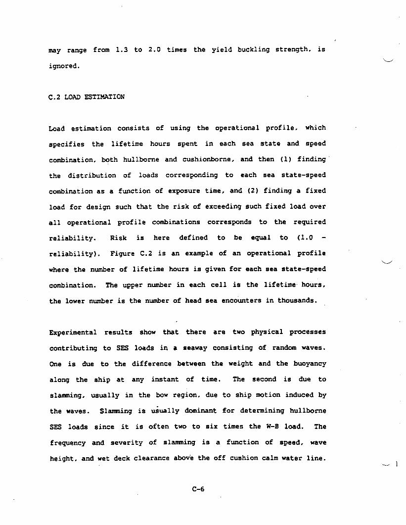
C.2 LOAD ESTIMATION
Lead estimation consists of using the operational profile. which
specifies the lifetime hours spent in each sea state and speed
combination. both hullbone and cushio*rne, and then (1) finding
the distribution of loads corresponding to each sea state-speed
combination as a function of exposure time, and (2) finding a fixed
load for design such that the risk of exceeding such fixed load over
all operational profile combinations corresponds to the required
reliability. Risk is here defined to be
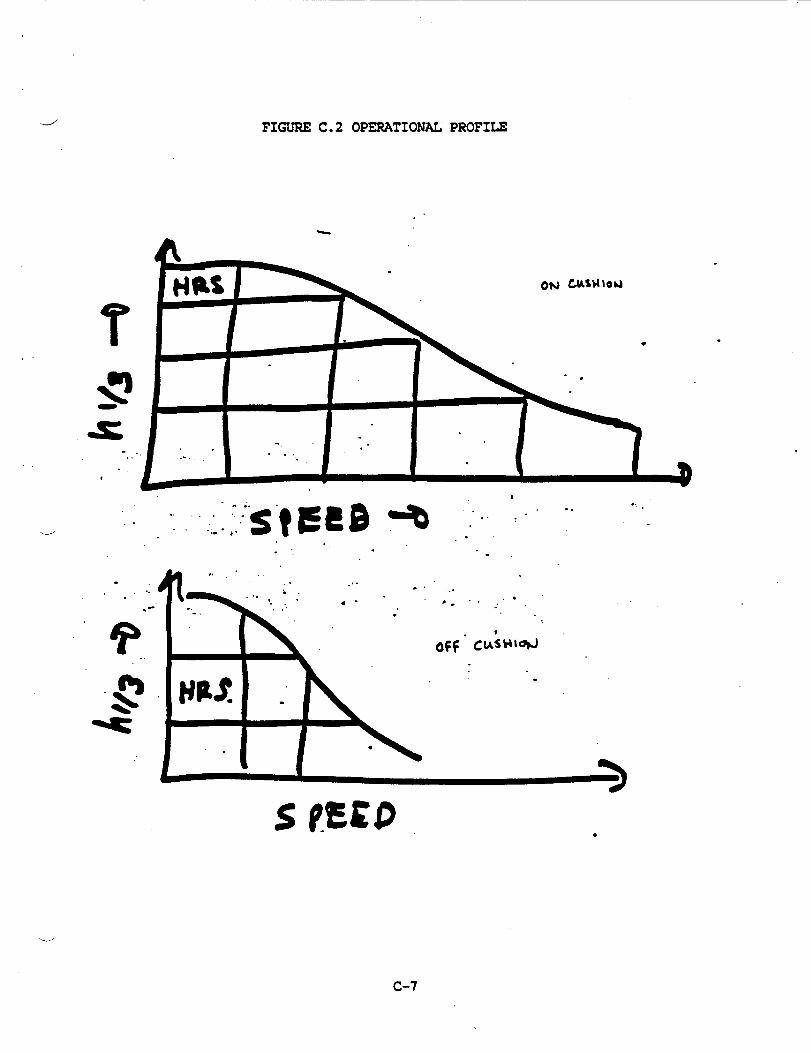
reliability). Figure C.2 is an example of an
where the number of lifetime hours is given for
combination. The upper number in each cell is
equal to (1.0 -
operational profileu
each sea state-speed
the lifetime hours.
the lower number is the number of
,
Experimental results show that
head sea encounters in thousands.
there
contributing to SES loads in a seaway
One is due to the difference between
are two physical processes
consisting of random waves.
the weight and the buoyancy
along the ship at any instant of time. The second is due to
slasmning,usually in the bow region, due to ship motion induced by
the waves. Slamming is ~ually dominant for determining hullborne
SES loads since it is often two to six times the W-B load. The
frequency and severity of slamming is a function of speed, wave
height, and wet deck clearance *v6 the off cushion calm water line.
C-6
.-/’ FIGURE C.2 OPERATIONAL PROFI~
.’-
.,.’
.
,..
““s”fgm *.. .. . ..... .. -..” ,.
.
-.,.:”
.
-,
?.”.-. ,. . . .
-. i..“.-” . .-. .
“?’.‘g HP$ “.
(
.
s
>
-..... ●
● -’,-.
.
...
c-7
.

There are two steps in using the load information: (1) find the
statistical distribution (called the parent distribution) which best
describes the data collected in a run, and (2) estimate the extreme
value corresponding to this distribution, the exposure time, and the
specified reliability.
PARENT DISTRIBUTION
The method of using the load magnitude information to estimate the
parent distribution parameter values from experimental data is as
follows: record the largest magnitude found in an interval of time
long enough such that the occurrence of one event does not influence
the magnitude of a subsequent event, i.e.. each event is independent
of other events. Order these events by nuqnitude from smallest to
largest. Estimate the values of the parameters of the statistical
distribution which best fits the data. A statistical distribution
which fits both the W-B forces and the slam forces is the Weibull
distribution with probability given by
P =1.o-@-(( (v-vO)’) (1)
P = probability that the value of the variable is V or less
= scale factor
v = variable such as load or response
Vo = truncation value (value below which the probability is
always zero)
“--’
w )
C-8
!.
.-J
characterizes the W-B “
distribution while c = 1 specifies an exponential distribution which
characterizes a slam distribution. The Weibull distribution has
also been found appropriate as in describing commercial ship loads,
Ref. C-2.
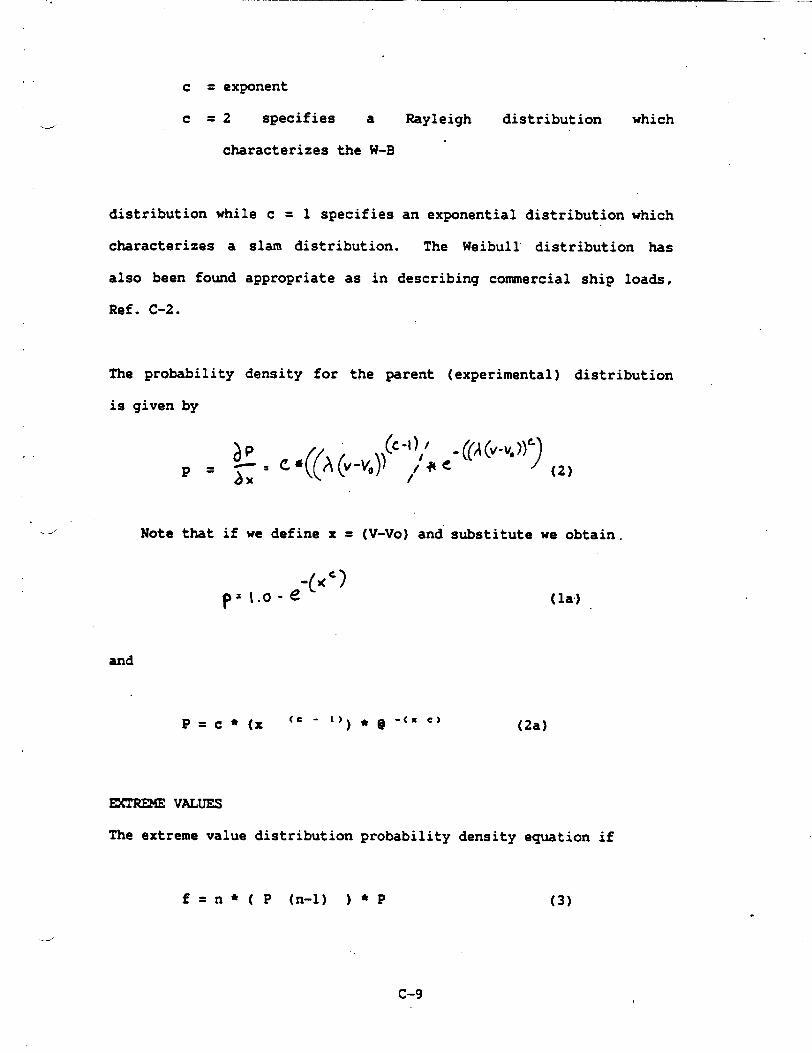
The probability density for the parent (experimental) distribution
is given by
,.
c = exponent
c = 2 specifies a Rayleigh distribution which
P
d Note that if we define x = (V-VO) and substitute we obtain.
and
(2a)
Emlu24E VALUES
The extreme value distribution probability density equation if
f =n ● ( p (n-l) ) * p (3).
.---’
c-9
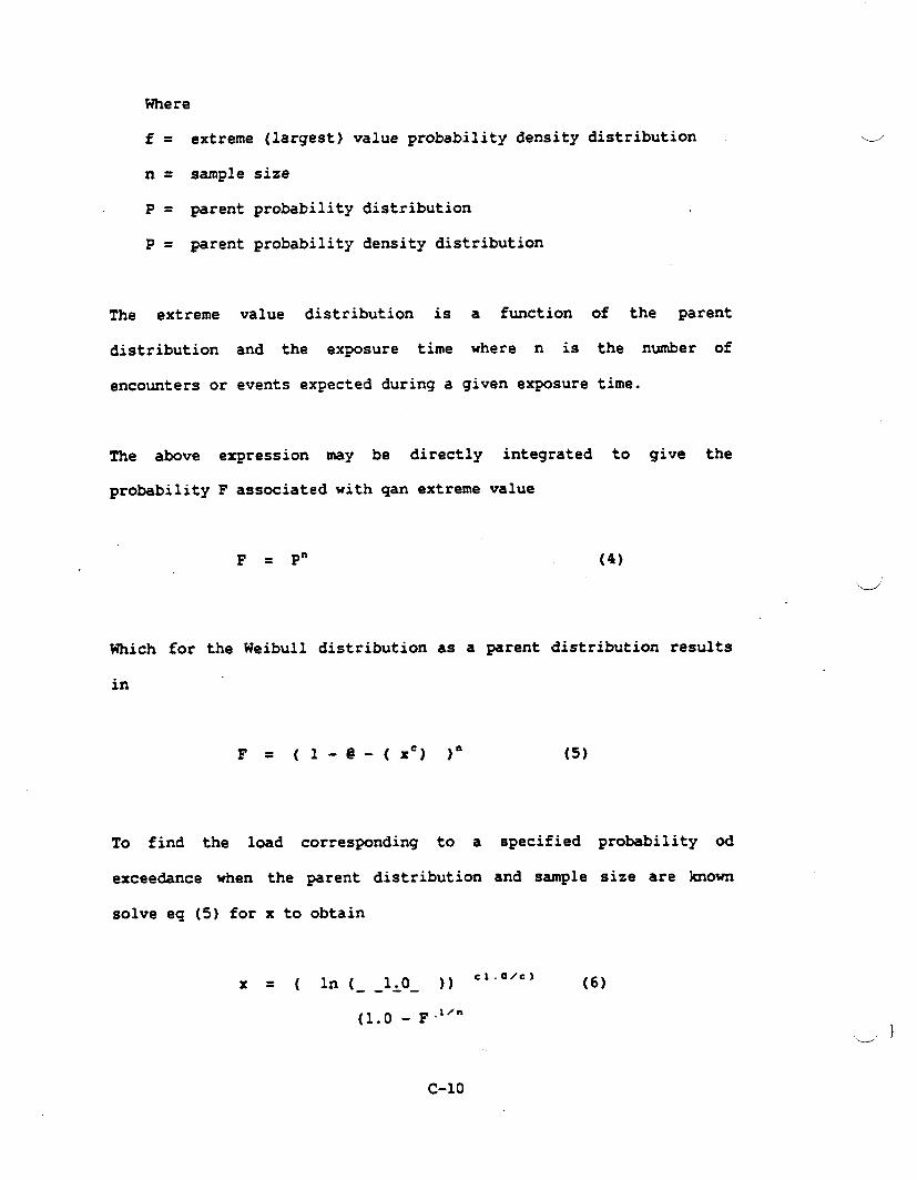
Where
f = extreme (largest) value probability density distribution
n= sample size
P = parent probability distribution
P = parent probability density distribution
.--”
The extreme
distribution
encounters or
value distribution is a function of the parent
and the exposure time where n is the number of
events expected during a given exposure time.
The above expression my be directly integrated to give the
probability F associated with qan extreme value
F = P“ (4)
Which for the Weibull distribution as a parent distribution results
in
F= (l-@-(x’) )“ (5)
To find the load corresponding to a specified probability od
exceedance when the parent distribution and sample size are known
solve eq (5) for x to obtain
x = ( in (__lAO_ )) C1.OZC) (6)
(1$0 _ F.;Zm
-)
c-lo

.
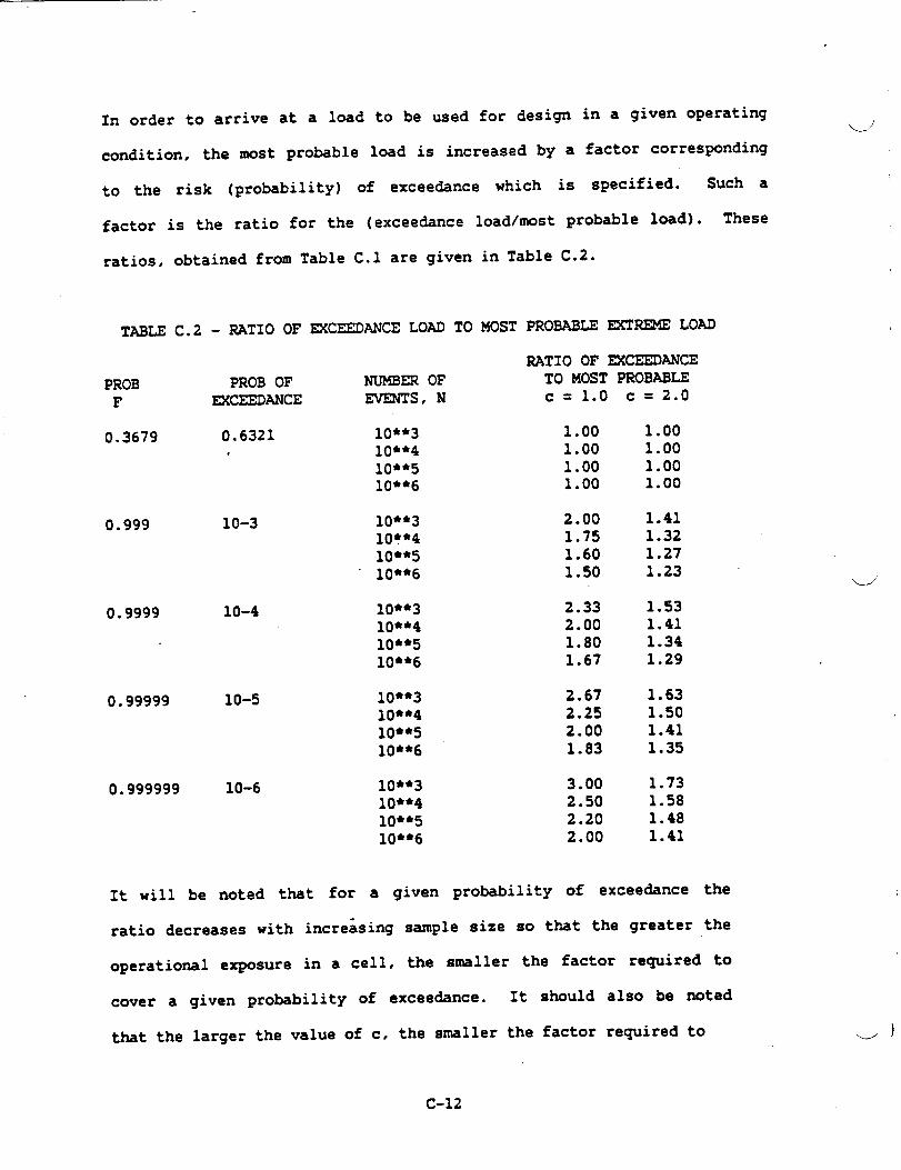
Table C.1 lists magnitudes of x for various values of F, n, and c.w
f is the ratio to the area below the value of x to the total area
(the promility), n is the sample size, and c is the slope of the
Weibull distribution.
TABLE C.1 - VALUE OF EK?EEDANCE LOAD FOR THE ~IBULL DISTRIBUTION
PROB_F_
0.3679
0.9999
4
PROB OFmKEEmNcE
0.6321
10-3
10-4
0.999 10-5
0.999 10-6
The most probably extreme
NUMBER OFEVENTS, N
10**31(J**410**510**6
10**310**410**510**6
10**310**410**510**6
10**310**410**5lo*~6
10**310**410**510**6
value (the
NON DIMENSIONALVALUE OF LOAD
c= 1.0 c = 2.0
6.908 2.6289.210 3.03511.51 3.39313.82 3.717
13.82 3.71716.12 4.01518.42 4.29223.03 4.799
16.12 4.01518.42 4.29220.72 4.55223.03 4.799
18.42 4.29220.72 4.55223.03 4.79925.33 5e033
20.72 4.55223.03 4.79925.33 5.03327.63 5.257
value at the peak of the extreme
value probability density curve) occurs, for the sample sizes shown, at F
= 0.368. This means that if 1,000 vessels were sent into the same sea
state for the same amount of time at the same speed, heading, and initial
load conditions, 632 of them would experience a load greater than the
most probable (most often occurring) load. It will be noticed that the
dmost probable load increases with the number of encounters (the exposure
time).
C-n
o .o .
i-? P. 0 s .
. 0 CJ
DJ
(t 0
.0 . m (A
lA
lP
P. G
0 Hl n .
I-J
.
ti 0) P. N m
. H rt
s’t-
.(n
(Y . N
)-w
P-
..
..
0000
0000
0 1-h
NJN
NW
..*.
ohJ1.no
0000
.
iD a .,
0000
0000
w .
(.(
( \.

cover a given probability of exceedance. Larger values of c
ucorrespond to non slam loadings. and so current practice from a
structural loads point of view is to have a high wetdeck clearance
hullbome, and to operate on cushion so as to minimize slanming
frequency and slamming magnitude.
WREME VALUE FOR DESIGN
The extreme value used for design is the one for which the risk of
exceedance, over the operational profile, meets the specified risk
of exceedance. For each cell in the operational profile there is a
given risk of exceedance of a specified
exceedance for the entire operational profile
of exceedance for all the cells. In order to-,
load. The risk of
is the statistical sum
proceed we need to a)
find the risk of exceedance in a given cell, and then b) sum”in a
probability sense the risk for all the cells.
a) Exceedance in a specific cell. Suppose the vessel has a
certain strength. Determine the probability of not exceeding this
strength for the operating conditions and duration specified for a
particular cell in the operational profile. For example, the first
line of Table C.3 shows the probability of not exceeding the
strength for operating condition cell one. Denote this reliability =
(1 - 3.62* 10-4) = 0.99963& byFl.
b) Overall reliability and risk. Having found the
reliabilities for each operating cell, find the overall reliability
by using
C-13

where
Rn= Fi (7)
‘.-.-
Rn= reliability for n cells
Fi = reliability for the ith cell
The risk is (1-Rn). Table C.3 shows typical
noted that the high sea state conditions, and
given sea
profiles,
which are
state, provide most of the risk.
results. it will be
the higher speeds in a
For most operating
most of the risk is associated with the boundary cells
called the operational envelope. Purther, for most hull
horn borne operating envelopes the high sea state operating
conditions (survival conditions) provides”most of the risk.
TABLE C.3 - RELIABILITY FOR
MOSTmmmrERs , WEIBULL
HEADSEA HULLBORNE OPERATIONAL RIJVELOPEOP1
PROBABLECELL THOusANDs SLOPE = C
N3.vl 20 1.0 10
H2,vl 90 1.4 6U2,V2 90 1.2 9
H3,V1 240 1.7 2H3●V2 250 1.5 4H3,V3 220 1.3 8
Overall reliability = 0.999638,
If the operating profile is changed, the
PROBABILITYSES OF =CEEDING
STRENGTH(RIsx)
18 3.62 * 10-4
18 7.76 ● 10-1918 3.74 ● 10-7
18 1o-1oo18 7.41 fi10-4718 1*O3 ● 1o-1o
Overall risk = 3.62 * 10-4
risk can again be estimated.
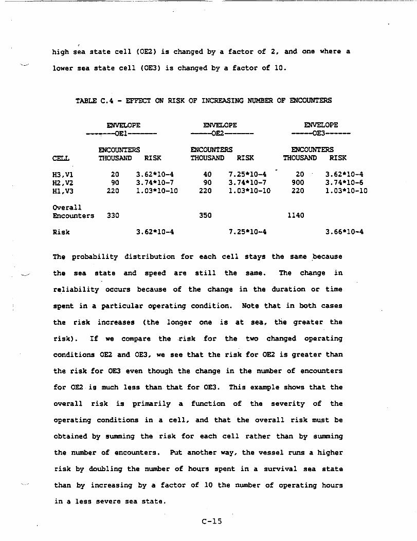
Table C.4 shows two such changes, one where the operating time in a
C-14
——.. . . .
e
high sea state cell (OE2) is changed by a factor of 2, and one where a
-.---’
lower sea state cell (OE3) is changed by a factor of 10.
TABLE C.4 - EFFECT ON RISK OF INCREASING NUMBER OF ~COUNTERS
~OPE--OEl--
ENCOUNTERSTHOUSAND RISK
H3,V1 20 3.62*1O-4H2,V2 90 3.74*1O-7H1,V3 220 1.O3*1O-10
OverallEncounters 330
Risk 3.62*1O-4
ENVELOPE---——0E2——————
ENCOUNTERSTHOUSAND RISK
40 7.25*1O-490 3.74*1O-7
220 1003*10-10
350
7.25*1O-4
ENVELOPE~E3—
mcomrrmsTHOUSAND RISK
.20 3.62*1O-4900 3.74*1O-6220 1.O3*1O-10
1140
3.66*1O-4
The probability distribution for each cell stays the same because
e the sea state and speed are still the same. The change in,
reliability occurs because of the change in the duration or time
spent in a particular operating condition. Note that in both cases
the risk increases (the longer one is at sea, the greater the
risk). If we compare the risk for the two changed operating
conditions 0E2 and 0E3, we see that the risk for 0E2 is greater than
the risk for 0E3 even though the change in the number of encounters
for 0E2 is much less than that for 0E3. This example shows that the
overall risk is primarily a function of the severity of the
operating conditions in a cell, and that the overall risk must be
obtained by summing the risk for each cell rather than by summing
the number of encounters. Put another way, the vessel runs a higher
risk
./ than
in a
by doubling the number of hours spent in a sunrival sea state
by increasing by a factor of 10 the number of operating hours
less severe sea state.
C-15 “

CUMULATIVE FATIGUE LOADING
h order to detemine whether fatigue is controlling the stress
level corresponding to a given load must be estimated.
The cumulative fatigue loading may be estimated by application of a
cumulative damage rule such as Miners rule:
.
ni =K (8)
Ni
ni = actual number of cycles at level i
NI = number of cycles at level i to cause failure
(usually
material)
K=. constant
obtained from
of summation,
S-N cu-es for the
L/”approximately 1/3 to
1/4 for 3 to 4 ship fatigue lifetimes
ln order to apply
loading cycles for
known since we have
Miner’s rule, we need to know the number of
each loading intensity. This information is
the experimentally estimated probability density
loading curves which were earlier used to estimate the extreme
values. AS before, we estimate the emulative fatiWe ~9e for
each cell, and then sum the C-lativf= fat@e ~9e for all cells
to find the overall fatigue damage. The stress which is used for “
computation is the nominal stress times the stress consultation
factor applicable at a particular location. If the fatigue stress
found for the lifetime number of loading cycles
cumulative damage stress, then the strength
C-16
is greater than the
of the vessel is
adequate. Due to uncertainties in the order of applied loads, the
vessel is usuallye
times greater-than
required to show a fatigue life which is 3 to 4
the estimated lifetime of the vessel.
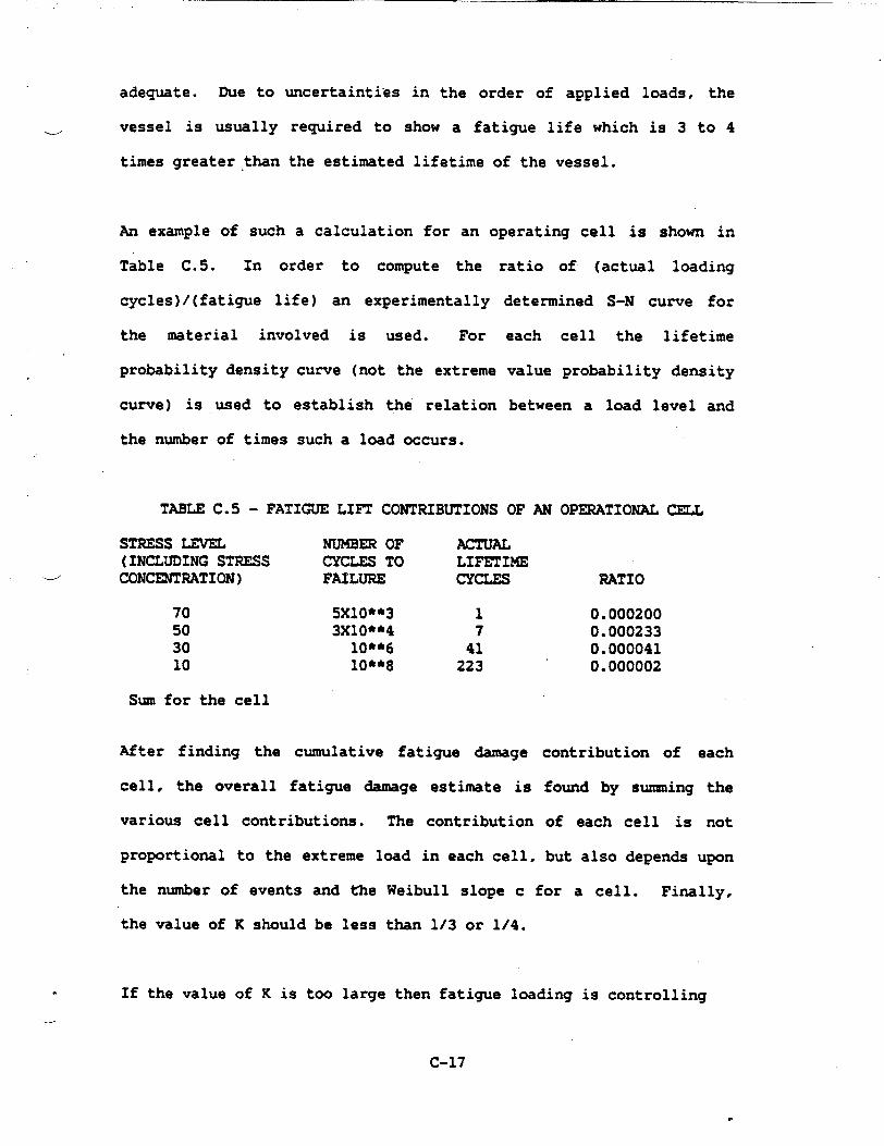
An example of such a calculation for an operating cell is shown in
Table C.5. In order to compute the ratio of (actual loading
cycles)/(fatigue life) an experimentally
the material involved is used. For
probability density curve (not the extreme
cuzwe) is used to establish the relation
the number of times such a load occurs.
TABLE C.5 - FATIGUE LIFT CONTRIBUTIONS
detemined S-N curve for
each cell the lifetime
value probability density
between a load level and
OF AN OPERATIONAL CELL
STRESS LEVEL NUMBER OF ACTUAL(INCLUDING STRESS CYCLES To LZFETIME
d CONCENTRATION) FAILURE CYCLES RATIO
70 5X1O**3 1 0.00020050 3X1O**4 7 0.00023330 10**6 41 0.00004110 lo*~8 223 0.000002
Sum for the cell
After finding the cumulative fatigue damage contribution of each
cell, the overall fatigue damage estimate is found by suzmningthe
various cell contributions. The contribution of each cell is not
proportional to the extreme load in each cell, but also depends upon
the number of events and the Weibull slope c for a cell. Finally,
the value of K should be less than 1/3 or 1/4.
. If the value of K is too large then fatigue loading is controlling
C-17

on the section rather than the once in a lifetime load and the
scantlings will have to be increased until the value of K is
satisfactory.
C.3 STRUC- DESIGN
Structural Design Criteria
The structural criteria specifies the load magnitudes and their
combinations,
properties and
the factors of safety, and sometimes the material
analysis methods of guides to be used.
Combined load sets are the sets of loads which occur simultaneously
on a stmctural element. Each set specifies the overall or global
loads, such as bending and vessel motion loads such as acceleration,
and local area loads such as fluid or point loads. Material
properties, rather than material allowable are specified. This is
consistent with using lifetime loads estimated from actual data.
In order to specify the combined factor of safety to be used in the
case of combined loads interaction equations have to be developed or
modified. Two points should be addressed. First, select the theory
which describes the criteria for the onset of damage to the
material, and secondly, determine how reliability based loads should
be combined with deteministically obtained loads. One possible
equation for estimating a combined factor of safety for tensile
‘..-/
.loads acting in the same direction is
C-18
‘- i

4
Esc = 1.0-
1.0 + 1.0
SY I FSG SY / FSL
SG SL
where
Esc=
FsG=
FSL =
SY=
SG =
SL =
combined factor of safety ( should be 1.0)
factor of safety for global or reliability based loads,
usually equal to 1.0 since the risk is already included
in the -gnitude of the load causing the stress SG
factor of safety for deterministically obtained load
yield stress of lrmterial
stress due to global or reliability based load
stress due to deterministically obtained load
Combined factor of safety equations should be specified for other
combined loading cases including compressive loads, out of plane
loads, and loads acting in different directions in plane.
.MATERIALS
Materials used to date for hulls are high strength marine service
aluminum alloys of the 5000 series. Craft include the SES-1OOA, the.
SES-1OOB, and the SES 200. Both 5086 and 5456 alloys have been
C-19

used. As SES sizes grow larger, the use of high strength steels
becomes attractive, especially those having yield strengths of 80
ksi and above such as HSLA, HY80, and HY1OO. The choice of which
material to use from a weight viewpoint is determined by comparing
the weight of an aluminum structure
sheathing against the weight of a
applications such as minesweeping,
plus any needed fire insulation
steel structure. For special
the use of plastic composites
such as GRP is often worth considering.
Minimum guaranteed (in the case of metals usually the as welded)
properties are nomally specified.
STRUCTURAL DESIGN
Since as SES is supported cushionbome by an air cushion whose
pressure is supplied by lift fans and whose
caused by the cushion pressure, attention to
pays off.
resistance is in part
minimum weight design
Once the structural criteria specifying the combined loads and
factors of safety is available, the remainder of the design can be
carried out by current design techniques including the use of
structural optimization programs such as described in Hughes Ref.
C-3 often
practice as
using, in the -case of Navy designs, current design
analysis guides.
The resulting structure is usually ~ longitudinally framed plate and
grillage structure. Closely spaced longitudinal stiffeners usually
C-20
Iw
result in a minimum weight design. Additionally, large amounts of
-J
permanent set are often
deck is usually close to
to longitudinal strength.
tolerated in the wet deck area since the.
the neutral axis and so contributes little
Information as to the shape of structural details to minimize
fatigue failure and to estimate the effect to misalignment may be
found, for example, in Ref. C-3.
STRUCTURAL FABRICATION NOTES FOR DESIGN
SES’S have the advantage that most of the vessel is composed of flat
panels forming relatively boxlike assemblies. Since the sidehulls
are narrow compared to ships of normal form, they may be shaped
&using flat plate elements joined together rather than being made up
of curved
t.makes the
minimizes
elements. The relatively large amount of flat plate work
use of automatic welding machines quite attractive and
the fabrication cost.
C-21

REFERENCES
Ref C-1 Gumbelt Statistics of fitremes
Ref C-2 Hunsee w.? et al.~ “Fatiwe Characteristics ‘f ‘abricated
Ship Details for Design,” Illinois University at Urbana,
Department of Civil Engineering, SSC-318. (Aug
Ref C-3 Hughest @en F*? “ShiP Structural Desi~ -
Based, Computer Aided, Optimization
Wiley-Interscience, (1983)
1982)
A Rationally
Approach,”
‘L.
c-22
\d

w
APPENDIX D
COMPARISON OF PRG AND US SCANTLING DIMENSIONS
-

—
D.1 ALU-ALLOY
.-_.’
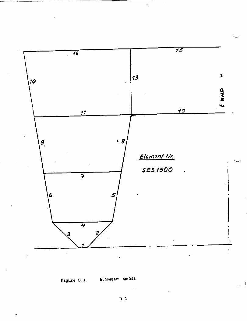
Figure D.1 shows the midship
text below.
The MTGsizing
element No. 7,
is provided for
10 and 11 as
stiffenings regarding elements
.
section with elements corresponding to the
smaller plate-thickness regarding the deck
well as smaller profiles of longitudinal
5 to .14.
Concerning the cross-stiffenings, the MTGversion provides for a floor
plate - regarding elements 1 to 4 - instead of T-profiles which are
stated in the US-version. Both results are nearly equal in weight.
i
Within the MTGversion even more weights result from element 12. The
d “M’I’Gversion shows this as “continuous longitudinal wall at _ .8* In the
US-version, this element consists of pillars.
The strength-calculation showed the necessity of this longitudinal wall.
An additional weight is caused by the thicker plate used with the lower
part of element 13.
Different longitudinal frame spacings were selected:
w
US Version: 13 inch (330 xmn)
German Version: 11.8 inch (300 mm)
.
D-1
.
\
14
7
—* ._w— ●
. .
75
?.
Figure D.1. &LEMEW r400a
D-2
.—
*
.
.
Similarly Web frame spacing were different:
w
US Version: Bulk-head spacing in drawing is 60 feet divided by 17 =
35.294 inches = 896 mm frame-spacing.
~G Version: 50 feet = 600 inches = 15.24 m: 15 parts @ 40 inch
(1016 m) frame-spacing.
The comparison of the distance of the longitudinal stiffeners shows, that
the MTG-version is provided for more “longitudinal frames” however less
“web frames”, which means for example: Half a wet-deck-width of 14 ft
(4.267 m) contains 14 “longitudinal frames” in the MTG-version and 13
“longitudinal frames” in the US-version.
..--’
The MTG-version shows for each compartment (600” = 15.24 m) 14 “web
frames” whereas the US-version plans 16 “web frames”.
Steel:
The MTGversion
and principally
shown in the
3.75 kg/m).
shows smaller plate-thickness in
for all elements the smallest
deck-elements 7 and 11
longitudinal frames as
US-profile-list (T-Profile 3x2x0. 125/0, 188 weight
In the US-version the smallest profiles are T 4x2x0, 188/0, 133 with a
weight of 6.728 kg/m.”
-
D-3
That means, the MTGversion contains a reduced weight for “longitudinal
frames” in comparison to the US-version. (The reduction of weight is
2,978 kgfm).
Regarding elements 1 to 4 the MTGversion contains as cross-stiffening a
“floor plate” which is neutral in weight in comparison to the
US-version. Additional weights are given in the ~Gversion
plate-thicknesses within the upper
and 16. Element 1 has been chosen
and lower hull elements
extremely thicker because
with higher
1,2,3,14,15,
it is meant
to be the keel-plate. The thichess for the other elements depends on
the strength calculation.
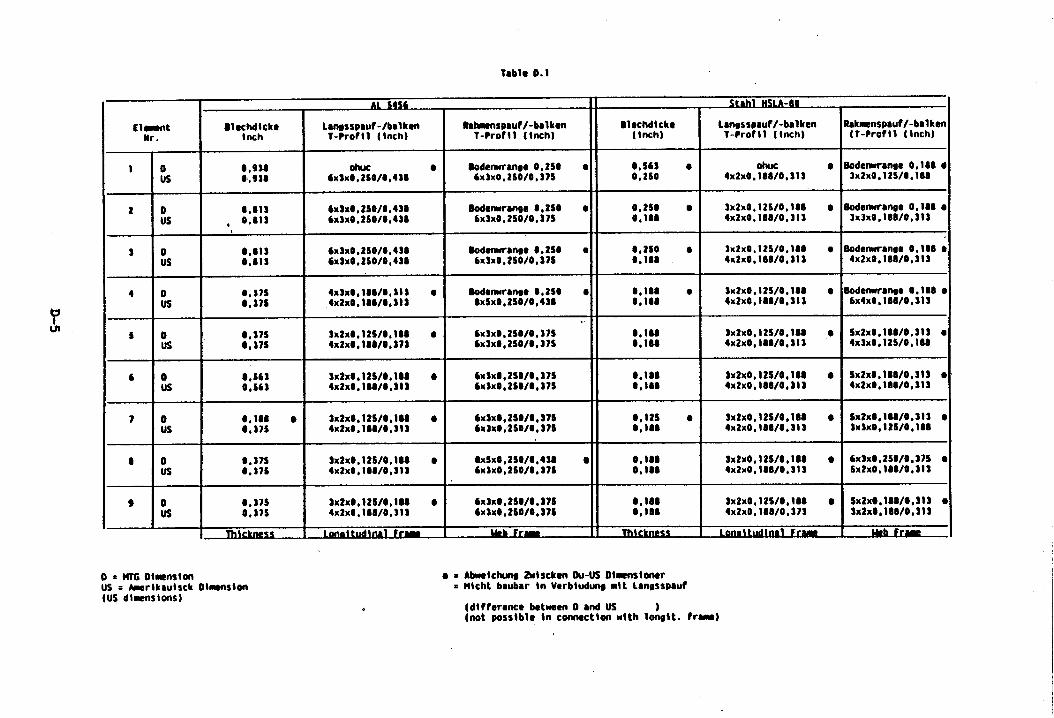
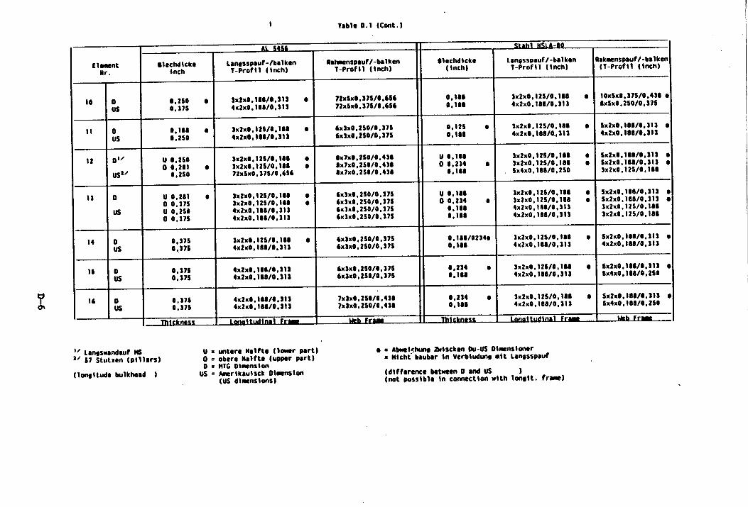
Table D.1 presents the full structural data for the design described
above.
D-4
)-.
‘?UI
ilep
*
10us
20us
i=
$0us
40us
5 0us
6 0us
7 0us
t ous
9 0us
1-
(
Tablo 0.1
------ 11 a..-., “I?.. .“AL SsM
SlocMtcko Lmgsspmf-/balken Rt~nspmIf /-bmlkon BlacMickc Lmssspauf/-balken Rakmenspauf/-bal kenInch T-Profll {inch) T-Profll (inch) (tnch) T-Proftl (tnch} (T-Proftl (Inch)
0,930 Olwc ● Oodemranse 0,2S. ● 0,563 ● OhUc0,938 6x3x0,2 S0/0,4U 6X3X0 , 2s0/0, 37$ 0,2s0
● Bodenxrmoe0,18064X2X0.108/0,313 3X2X0,12s/0,188
0,81s 6x3x0,2S0/0,4U Bodenxren9e.,2S0 ● 0,2s0 ● 3x2xo,12s/o*lu, 0.s1s 6xSx0.2S0/0,43S 6x3x0,2SO/O,S7S
● Oodenxrange0,180●O,lu 4x2x0,lM1/O.313 3x3xo,lea/o,313
0,813 6x3x0,2S0/0,430 Oodenxmnge0.2S0 ● 0,2s0 ● 3x2x0,12S/0,1800,013 6x3x0,2S0/0,430 6x3x0.2S0/0,37S O*IU
● Bodenwmwe 0,100 ●
4x2x0,100/0,313 4x2x0,100/0,313
S,S7S 4x3xo,lso/s,313 ● Bodenxrmee O,2SS ● Coloo Q 3x2xo,12s/o,loo0,37s 4x2x0,10S/0,S13 0xSx0,250/0,43S 0,100
● Bodwxmmoe0.180●4X2X0,188/0,313 6x4x0,lSO/0,3~3
.0,37s 3x2x0,12S/O,\OI ● 6x3x@,2S0/0,37S 0,100 3x2x0, 12S/0, IU ,0 Sx2x0,100/O.313 ●
0,37s 4x2x0,1 U/0,373 6x3x0, 2S0/0, 37S 0,100 4x2x0, lU1/0, 313 4X3X0,12s/0, 100
0,S63 3x2x0, 12S/0, MO ● 6x3x0,2 S0/0,37S 0,100 3x2x0, 12S/0, 100 ● Sx2x0, tS0/0,313 ●
0,S63 4x2x0 .lSO/0,313 6x3x0,2 S0/0,375 0,180 4x2x0,100/0,313 4x2x0.180/0,313
0,10s ● 3x2x0, 1?S/0, 110 ● 6x3x0,2 S0/0,37S 0,12s ● 3x2xoo12s/o,loo ● Sx2x0,1t0/0,3t3 ●
0,375 4x2x0,100/0,31S 6x3xO;2S0/0,37S O,tu 4x2x0,100/0,313 3X3XO*12s/0, 100
0,37s 3X2X0,12s/0, 100 ● 0xSx0,2S0/0,430 Q 0.100 3x2x0, 12S/0 ,100 ● 6x3x0,2S0/O ,37S ●
0,37s 4x2x0, 100/0,31 3 6X3X0,2s0/0, 376 0,100 4x2x0, 180/0, 313 Sx2x0,100/0,313
0,31s ax2xo,12s/o,lu ● 6X3X0, 2s0/0 ●a7s 0,1000,37s 4x2x0 , 100/0,313
3x2x0, 12S/0, 10S ●
tx3x0,2S0/0,37SSX2X0.1W0, S13 ●
0,10s 4x2x0 , 1S8/0 ,373 3x2xO,1OWO,313
o .~ Oimnston Q s Abxetdxxtg Zidscken OU-USOlmstoncrus = Amsrikaulsck Otmnsien = Wtcht bmbar in Verbhdm mttLanosspauf(US d~m$ions)
(dt fference between O ●d US(not possibl. in cmecthn with lc&t. from)
-●
m_.
●☛●
●m.
No
.-..
m.
=0
uII
*It
son
g●
0--
mo
ma
--
0“0“0“=0
>Oao
1-
um
Na
D-6

-.-.-’
APPENDIX E
AUXILIARY SYSTEMS DETAILED
E.1
E.2
E.3
E.4
E.5
E.6
E.7
E.8
E.9
>’4“
Criticality Analysis
Drainage Systems
HVAC Systems
Fresh Water Systems
Fuel Systems
CHARACTERISTICS
Methodology
Compressed Air and Nitrogen Systems
Fire Extinguishing Systems
Hydraulic System
Refrigeration System
The systems discussed in Appendix E were not developed specifically for
the NASW SES. They were developed and proposed for other SES designs,
principally for the U.S. 3KSES. They are presented as general background
only.
—

.
APPENDIX E.1
CRITICJULITY.ANALYSIS FOR AUXILIARY SYSTEMS
----’
\

——
.
The definitions used for this analysis are as follows:-
(1) Technology Critical -(rating of 5)
(2) Mission Critical(rating of 4)
(3) Capability Critical(rating of 3)
(4) Design Critical(rating of 2)
(5) Non-critical(rating of 1)
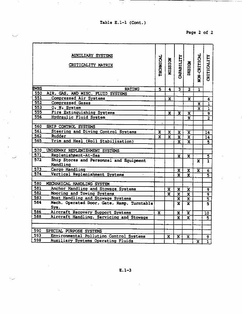
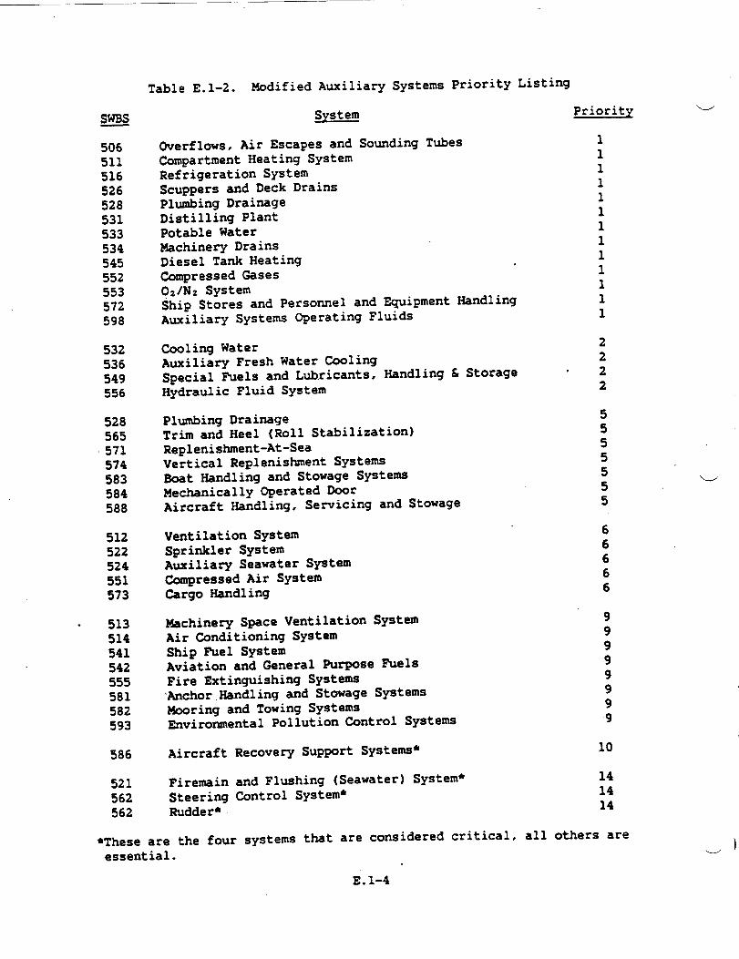
.--’ Ratings were assigned
evaluated as shown in
the system priority
A set of guidelines
A system or element which is criticalfor the mission but has not beenpreviously engineered for SESapplications.
A basic system or element which isrequired to allow the craft to beoperational.
A system or element which is requiredto demonstrate capability relative to“test drivers”, e.g., helicopteroperations, etc.
to these five
Table El-l.
A system or element which has previousSES engineering but requiredmodifications to suit optimum craftconfiguration.
Existing technology satisfactory.
definitions and
The matrix was
Table E.1-2.
.
all auxiliary systems
then used to develop
listing shown in
for each critical auxiliary subsystem was prepared to
encompass: approval hierarchy, operational, performance, and design
requirements. Standard coasnercial, U.S. Caast Guard, and U.S. Navy
design criteria were used to determine
concepts. The major selection criteria
cost, weight, safety and technical risk.
system requirements and derive
for an applicable design were
E.1-1
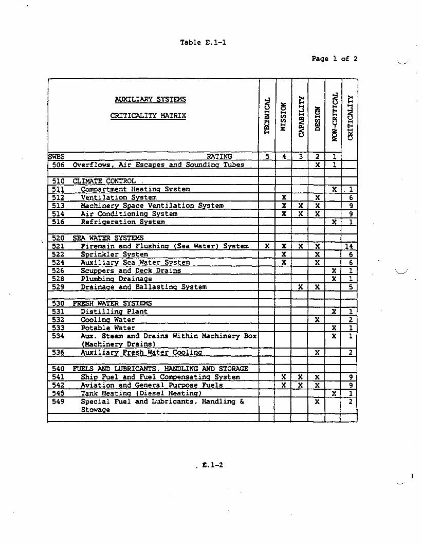
Table El-l
Page 1 of 2
I
AUXILIARY SYSTEMS
CRITICALITY MATRIX
SwBs RATING506 Overflows, Air Escapes and Sounding Tubes
]510 CLIMATE CONTROL511 Gmpartment Heating System512 Ventilation System513 Machinery Space Ventilation System514 Air Conditioning System516 Refrigeration System
., 520 SEA WATER SYS=521 Firemain and Flushing (Sea Water) System522 Sprinkler System524 Auxiliary Sea Water System526 ScupPers and fleckDrains528 Plumbing Drainage529 Drainage and Ballasting System
530 FRESH WATER SYSTEMS531 Distilling Plant532 Cooling Water533 Potable Water534 Aux. Steam and Drains Within Machinery Box
(Machinery Drains)536 Auxiliary Fresh Water Cooling
540 FUELS AND LUBRICANTS, HANDLING AND STORAGE541 Ship Fuel and fiel Compensating System542 Aviation and General PurPose Fuels545 Tank ?ieatinq(Diesel Heating)549 Special Fuel and Lubricants, Handling &
Stowage
5———
———
4——
—
ii-—
———
—
T-Yx-————
———
———
—
.——
.
——
xii-——
——
Ix .1x 6
x x 9x x 9
x ,11 1 I
I I 1
ZEEE
+Ex 6
xlxl
xx 5
Exl
x 2xlxl
x 2
Bxx 9xx 9
xlx 2
I I I
L.-’;
. E.1-2
— —“
Table El-l (Cont.)
Page 2 of 2w
.-...’
AUXILIARY SYST~
CRITICALITY MATRIX
ptms RATING550 AIR, GAS, AND MISC. FLUID SYSTEMS551 Compressed Air Systems552 Compressed Gases
t553 t)2~2 System555 Fire Extinguishing Systems556 Hydraulic Fluid System
560 SHIP CONTROL ~STE24S561 Steering and Diving Control Systems562 Rudder565 Trim and Heel (Roll Stabilization)
570 UNDERWAY REPLENISHMENT SYST324S571 Replenishment-At-Sea572 Ship Stores and Personnel and Equi~ent
Handling573 Cargo Handlinq574 Vertical Replenishment Systems
580 MECHANICAL HANDLING SYST~581 Anchor Handlinq and Stowage Systems582 Mooring and Towing Systems583 Boat Handling and Stowage Systems584 Mech. Operated Door, Gate, Ramp, Turntable
Sys.586 Aircraft Recovery SUPPOrt Systems588 Aircraft Handling, Servicing and Stowacre
590 SPECIAL PURPOSE SYST~593 Environmental Pollution Control Systems598 Auxiliary Systems Operating Fluids
gi_
-
T-z-
R-
I I
3E-Xxx
x
xxxxxx
#
xx
xx
3ZI=
Exxxxxx
xxxx
xxxx
=xxx
I I
xz-
ir-ii-
x
5-i
6T——
9T.
E.1-3
~
506511516526528531533534545552553572598
532536549556
528565~571574583584588
512522524551573
. 513514541542555581582593
586
521562562
Table E.1-2. Modified Auxiliary Systems Priority Listing
SY&!%!!Priority
overflow, Air E=w @ so~ding T~EH3Compartment Heating SystemRefrigeration SystemScuppers and Deck DrainsPlumbing DrainageDistilling PlantPotable WaterMachinery DrainsDiesel Tank HeatingCompressed Gases02/Nz SystemShip Stores and Personnel and Equipment HandlingAuxiliary Systems Operating Fluids
Cooling WaterAuxiliary Fresh Water CoolingSpecial Fuels and Lubricants, Handling L Storage “Hydraulic Fluid System
Plumbing DrainageTrim and Heel (Roll Stabilization)Replenishment-At-SeaVertical Replenishment SystemsBoat Handling and Stowage SystemsMechanically Operated DoorAircraft Handling, Servicing and Stowage
Ventilation SystemSprinkler SystemAuxiliary Seawater SystemCompressed Air SystemCargo Handling
Uachinery Space Ventilation SystemAir Conditioning SystemShip fiel SystemAviation and General Purpose FuelsFire Extinguishing Systems‘AnchorHandling and Stowage SystemsMooring and Towing SystemsEnvironmental Pollution Control Systems
Aircraft Recovery Support Systems*
Firemain and Flushing (Seawater) System*Steering Control System*Rudderh
1111111111111
2222
5555555
66666
99999999
10
141414
●These are the fouressential.
systems that are considered critical, all others are
w
-)
E.l-4

,, — —— .—
‘..---’
APPENDIX E.2
DRAINAGE SYSTEMS
o
.---’
.

SYST~ REQUIREMENTSw
The ship drainage system consists of plumbing drains, scupper and deck
drains, oily waste collection, and main and secondary drainage. The
design requirements of the system are outlined in General Specifications
for Ships of the U.S. Navy, Sections 528, 529 and 534. Specifically, the
following requirements were identified for the Drainage System of the
3KSES design:
a.
b.
c.
---- d.
e.
f.
9*
h.
Segregation of soil and sanitary waste drains.
Plumbing drains for all plumbing fixtures.
Independent drainage for sanitary drains from commissary spaces
and medical spaces.
Air gaps in drain lines from refrigerators, hot food tables and
similar equipment.
Plumbing drains penetrating watertight
a full port ball or plug valve operable
damage control deck.
transverse bulkheads have
at the valve and from the
Space deck and weather deck drains
accumulation of water on weather and
provided to prevent
hangar decks, decks of
sanitary and comissary spaces and decks in other spaces where
water may accumulate.
Independent drains for the hangar, magazines, and R.A.S. stations.
Main drainage to have the capability of evacuating water from
propulsion engine rooms,
Pump rooms at a rate of
conditions. Seawater pump
dewatering capacity to the
combustion air intakes, and auxiliary
not less than 500 gpm under emergency
“bilge injection will provide a boosted
propulsion engine rmms.
E.2-1

i.
j“
k.
1.
m.
Il.
u
Secondary drainage via drain pumps provided from drain wel’ls in
lift engine rooms, auxiliary machinery rooms, electrical
generator rooms, and the propulsion engine rooms.
Secondary drainage eductors provided for drainage of lift fan
rooms, and of the combustion air intakes. Drainage requirement
per lift fan is up to 33 gpm average continuous and to 116 gprn
intermittent.
Damage flooding in compartments not served by the main drainage
eductors will be handled by submersible pumps.
Main drainage control shall be both locally and at the damage
control auxiliaries and electrical console (-).
The secon&ry (waste water) drainage system and the oily waste
collection system are segregated.
A waste oil system which collects oils at discrete points from
lift
lube
the
and propulsion engines, gas turbine generators,
oils, oil seepage from engine gearboxes and waste
aviation and general workshop. (Oily water
drainage is part
expended \-/’
oils from
separator
of the Pollution Control System.)
CANDIDATE CONCEPTS
plumbing drainage system
flow and a system which utilizes fresh water flushing and vacu~
collection.
TRADEOFFS — Two candidate concepts for the
were examined; the conventional seawater gravity
Conventionally, soil and waste
the driving force. Associated
drains have relied solely on gravity as
with this approach have been restrictions
with regard to piping slopes (1/2 “inchper foot minimum) and to the use
J
E.2-2
of piping sizes compatible with standard gravity operated fixtures. Inw
particular, water for flushing of water closets has usually been seawater
with the resulting soil waste generation rate of 30 gallons per capita
per day (GPCD). When the ship is within the prohibited discharge zone
this places unnecessary loading on sewage treatment units andior on the
collection, holding and transfer tanks (CHT). Water closets are
presently available which substantially reduce the quantity of soil
wastes resulting from each flush. Table E.2-1 lists some of these units
and the methods employed to obtain the controlled flush volumes. The
quantity of water utilized by the various units (1/4 to 1/2 gallons per
flush) is a reduction of approximately 90% over conventional gravity
systems which require 4 to 5 gallons per flush of the non-vacuum operated>
systems, the GATX water closet utilizes the least quantity of waste water
-+ per capita day, but its weight (80 lbs. with necessary valves) does not
represent any saving over the stan&rd shipboard unit. The GATX unit is
not vacuum operated and macerator/transfer pump(s) are used in the
installation to propel the waste slurry along the piping. The Jered
water closet/controlled urinal system with the resulting combined waste
rate of 1.92 gallons per capita day is vacuum operated. The water closet
weight is 33 lbs. complete with the necessary control and discharge
valves. This is a weight reduction of 42
unit, for a total saving of 588 pounds
with 14 water closets.
pounds per unit over a standard
for the SES, which is equipped
Vacuum collection system for soil drains, in addition to re~lringconventional gravity drain piping and fittings, includes vacuum pump(s),
vacuum collection tank(s), vacuum interface valves, and electrical
E.2-3
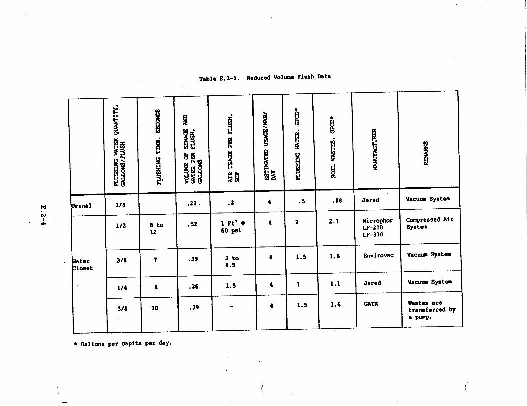
-----
I
ttt==
==
tIHsITld/sNomw
‘&UUl@)
U?LY
MSfHHSf17J
1
1,
II
8
J-
E.2-4

.,,:
instrumentation and control. The vacuum interface valves are located inw
_.
-J
the drainage lines close to the urinals and control the application of
vacuum and atmospheric air to the transported liquid waste. A brief
weight comparison between the ship and seawater gravity drains and with
the vacuum collection concept is given in Table E.2-2. The equipment
weight penalty incurred by the vacuum concept is approximately .23 long
tons. This weight penalty is soon absorbed when compared to the weight
of liquid collected and retained when the ship is operating within “
prohibited discharge zones. Using an overall daily soil accumulation
rate of 30 GPCD for a conventional seawater system and 1.92 GPCD for the
vacuum system, the weight saving in stored liquid is illustrated in
Figure E.2-1. After a twelve hour period in a non-discharge zone, a 6.3
long ton differential would exist in favor of the vacuum system. This
differential increases to 9.5 long tons after 18 hours, which is the
designed holding time capacity of the vacuum collection tank system.
For the ship’s one day CHT holding capacity. the weight differential
would be approximately 12.8 long tons. In addition to the weight
savings, the following advantages of the vacuum system can be listed:
.- Piping runs need not be sloped, thereby facilitating installation
by standardization in the length of pipe hangers.
- Higher flush differential pressure allows the use of smaller pipe
and valve sizes.
- Line leakage is from the compartment(s) into the drain lines,
thereby reducing the risk of fluid contamination.
- The number of piping vent lines is greatly reduced: venting of -
the collection holding and transfer tank providing this function
for the complete system.
I
E.2-5
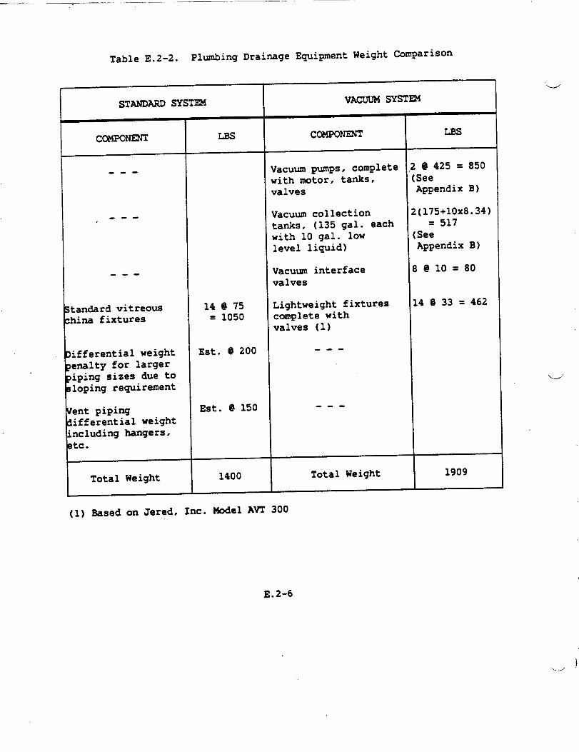
Table E.2-2. Plumbing Drainage Equipment Weight Comparison
r
STANDARD SYST~
ccMPoNEm
I
---
---,
---
Standard vitreouschina fixtures
Iinferential weightenalty for largeriping sizes due toloping requirement
Ient pipinginferential weight“ncluding hangers,tc.
I Total Weight
1
LBs
14 @ 75= 1050
Est. @ 200
Est. @ 150
1400
V= SYSTEM
CCUWNENT I ms,
Vacuum pumps, comletewith motor, tanks,valves
Vacuum collectiontanks, (135 9al. eachwith 10 gal. lowlevel liquid)
Vacuum interfacevalves
Lightweight fixturescomplete withvalves (1)
---
---
Total Weight
(1) Based on Jered, Inc. Model AVT 300
! @ 425 = 850:SeeAppendix B)
1(175+1OX8.34)= 517
[SeeAppendix B)
3@10=80
14 @ 33 = 462
1909
E.2-6
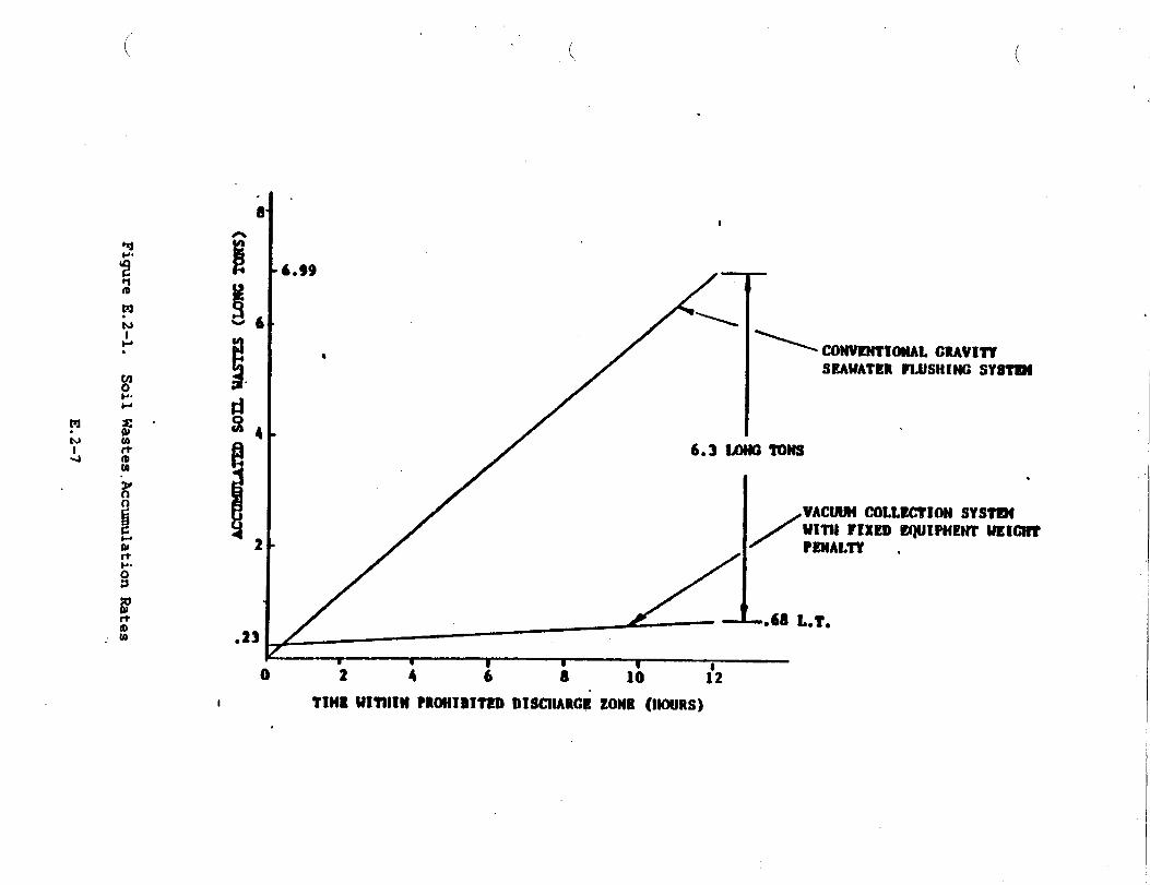
.
._/’
.
\
w—
.
m4“\’
I
0
mz0N
ti●
FigureE.2-1.
SoilWastes.AccumulationRates
.
E.2-7
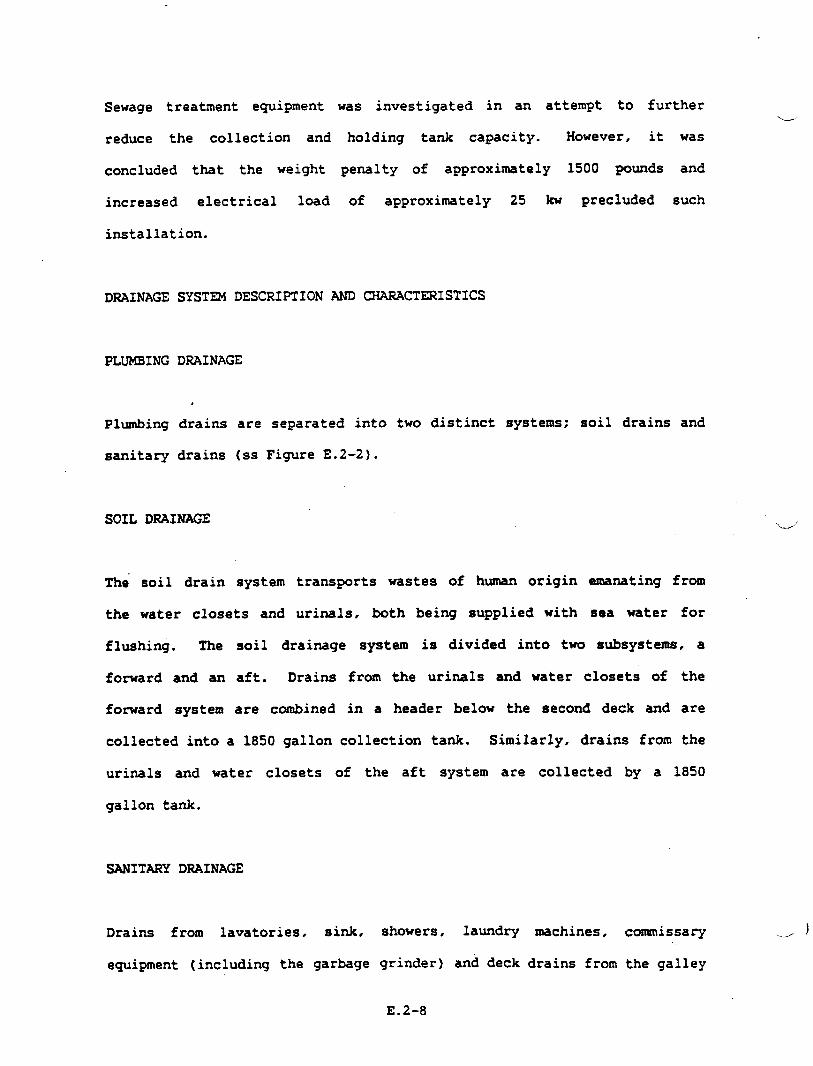
Sewage treatment equipment Was investigated in an attempt to further
reduce the collection and holding tank capacity. However, it was
concluded that the weight penalty of approxi=tely 1500 pounds and
increased electrical load of approximately 25 b precluded such
installation.
DRAINAGE
PLUMBING
Plumbing
sanitary
SYSTEM DESCRIPTION AND
DRAINAGE
.
CHARACTERISTICS
drains are separated into
drains (ss Figure E.2-2).
SOIL DRAINAGE
two distinct systems; soil drains and
The soil drain system transports wastes of human origin
the water closets and urinals, both being supplied with
u
emanating from
sea water for
flushing. The soil drainage system is divided into tm subsystems, a
fonard and an aft. Drains from the urinals and water closets of the
fozward system are combined in a header below the second deck and are
collected into a 1850 gallon collection tank. Similarly, drains from the
urinals and water closets of the aft system are collected by a 1850
gallon tank.
SANITARY DRAINAGE
Drains from lavatories, sink, showers, la~dry =chines, commissary -)
equipment (including the garbage grinder) and deck drains from the galley
E.2-8
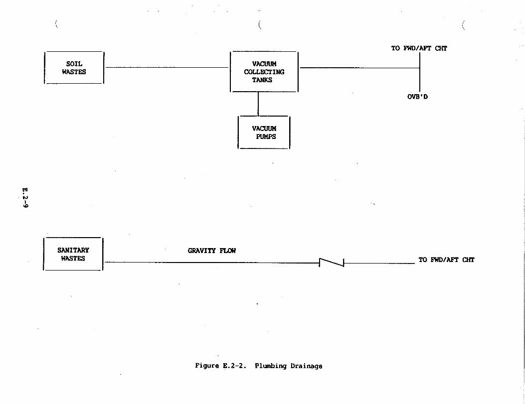
!s\—E
Id
0El
E.2-9

and the scullery are transported by the sanitary waste drainage system.
This gravity system consists of two sub-systems, one foward and one aft.
Waste drains from the vegetable
tables, kettles, ice machines,
discharged through an air gap to
peeler, dishwasher, refrigerators, steam
commissary sideboards and dressers are
the drain system.
The drain piping, mde of GRp material,.is pitched a minimum of 0.23 inch
per foot.
Drains from the medical treatment room are led independently to the
forward CHT.
Piping penetrating watertight transverse bulkheads utilize motor driven
full ported ball valves. These can be operated manually, or can be
controlled electrically
SCUPPER AND D= DRAINS
at the -.
These drains are grouped as
subdivision transverse bulkheads
much as possible between watertight
and led overboard via scupper valves.
Valves below the damage control deck are of the gag-type and can be
remotely operated from the second deck via reach rods. Piping material
is aluminum. Overtiard discharges are fitted with hose connections to
permit attachment of portable
from the helicopter hangar is
trunked for fire protection.
CRES.
w’
submersible pump discharges. Drain piping
independently led directly overboard and is
The. piping rmterial for these drains is
E.2-10
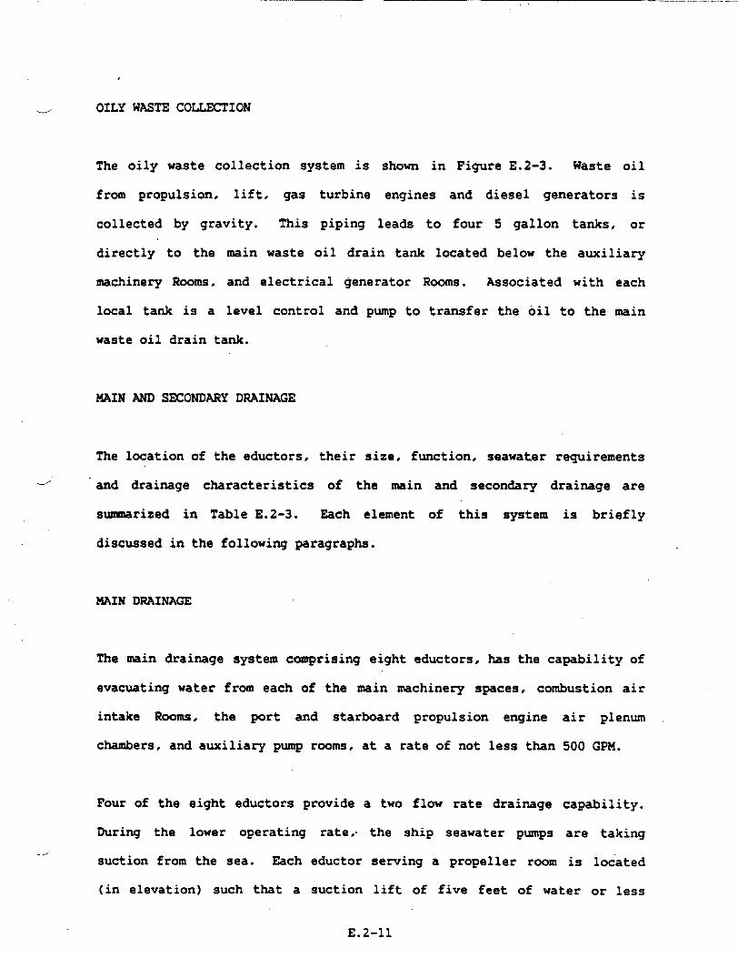
..——
e
.--’ OILY WASTE COLLECTION
The oily waste collection system is shown in
from propulsion, lift, gas turbine engines
collected by gravity. This piping leads to
directly to the
machinery Rooms,
local tank is a
Figure E.2-3. Waste
and diesel generators
four 5 gallon tanks,
oi1
is
or
main waste oil drain tank located below the auxiliary
and electrical generator Rooms. Associated with each
level control and pump to transfer the oil to the main
waste oil drain tank.
MAIN AND SECONDARY DRAINAGE
The location of the eductors, their size, function, seawater requirements
-/ and drainage characteristics of the main and secondary drainage are
summarized in Table E.2-3. Each element of this system is briefly
discussed in the following paragraphs.
MAIN DRAINAGE
The main drainage system comprising eight eductors, has the capability of
evacuating water from each of the main machinery spaces, combustion air
intake Rooms, the port and starboard propulsion engine
chambers, and auxiliary pump rooms, at a rate of not less than
Four of the eight
During the lower
eductors provide a two flow rate drainage
operating rate,. the ship seawater pumps
.suction from the sea. Each eductor serving a propeller room
air plenum
500 GPM.
capability.
are taking
is located
(in elevation) such that a suction lift of five feet of water or less
E.2-11
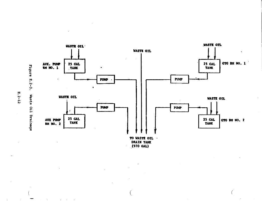
d*i
FigureE.2-3.
WasteOilDrainage
E.2-12
.-”’

*
(
TabloE.2-3. 14einand SecondaryDrainag.Eductors
(
M“b
DRAINAGEFLCURATE SEAWATERSUPPLYREMTED INLEfLIFT, FLOW & PRESSURE
LOCATI~ FUNCTION SIZE DISCHARGEHEAD REQUIRED(INCH)(2) (?-r.Hlo) GPM PSIG
Transducer/PUel Naindrainagaof PumpRoomNo. 1 ●nd 6x6x4 500 gpm e 15* Lift 340 100lbNo. 1 6-56-1-Q starboardsidewallaftsegment withup to 20’
Head (1)Transducer/Puel Naindrainageof PumpRoomNo.2 and 6x6x4 500gpn@ 15”Lift 340 100- No. 1 6-56-2-Q portsidewallaftsegment withup to 20’
Head (1)Tranaducar/Pua~ Nain drainage of PropulsionEngine 6x6x4 500gpm@ 15’Lift 340 100~ No. 1 6-56-2Q Rm91&2, AuxPumpRmNo. l,and withup to 20’
portpropulsion ●ngineplenumchamber Head (1)CamtmetionAir Intake Nain drainagaof CunbuationAir 6x6x4 500 gpm @ 15’ Lift 340 100No. 1 3-38-14 IntakeNo. 1 with up to 20’.’ Head (1)
Cuabustion Air Intake 14ein drainageof CcxnbuationAir 6x6x4 500 gpm @ 15’ Lift 340 100No. 2 3-38-1-Q IntakeNo. 2 with Up to 20’HeadCambuationAirIntake Secon&ry drainagaof Combustion 2x2x11/4 40gpm@M’ Lift 28 100No. 1 3-38-2-Q Air IntakeNo.2 with up to 20’HeadCoinbuationAirIntake Secon&ry drainagaof Cunbuation 2x2x1U4 40gpm@15’ Life 28 100No. 2 3-38-2-Q Air IntakeNo. 2 with up to 20’ HeadLift Fan M No. 1 Secon&ry drainagaof Lift Fan 3x3x2 116 gpm @ 12’ Lift 75 1004-8-14 RrnNo.l!13 with-upto 20’ HeadLift FankNo. 2 Secondarydrainageof LiftFan 3x3x2 116gPmQ 12’Lift 175 1004-8-2+ RnNo.2L4 with up to 20’ HeadLift FanRm No.1 Secondarydrainag.of LiftFan 4x4x3 235gpm@ 15’Lift 175 1004-8-1-Q RmNo. l&3 withup to 20’ HeadLift Fan IbNo. 2 Secon&ry drainageof Lift Fan 4x4x3 235gpm@ 15’Lift 175 1004-8-2-Q I?JnNo.2&4 withup to 20’ HeadAux Pmp RmNo.1 Main drainageof Aux Pmp RD 4x4x3 J75gpm@ 15’ Lift —
with up to 20’ Head —Aux Pmp SmNo.2 Nain drainagaof AM Pmp RIE 4x4x3 175 gpm @ 15’ Lift —
with up to 20’ Head —
Notes:1. Drainageflow rate is 620 gpm O 5’ liftwith up to 25’ head.2. Sizemgiven referto the size
to the suction and discharga;of end connections.The firmtand eecondnumberthe laat numberto the drivingfluidconnection.
apply
,.
.>
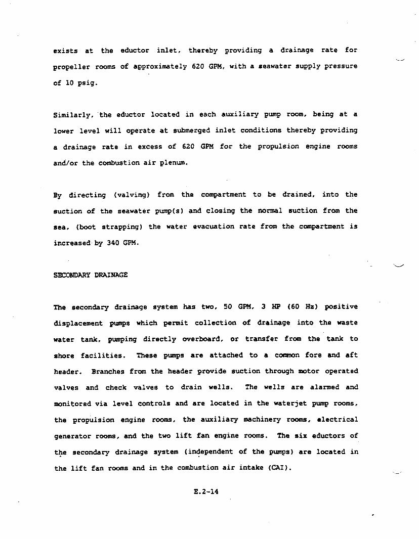
exists at the
propeller rooms
of 10 psig.
eductor inlet, thereby providing a drainage rate for
of approximately 620 GPM, with a seawater supply pressurew
Similarly, the eductor located in each auxiliary pump
lower level will operate at submerged inlet conditions
room, being at a
thereby providing
a drainage rate in excess of 620 GPZ4 for the propulsion engine rooms
and/or the combustion air plenum.
By directing (valving) from the compartment to be drained, into the
suction of the seawater pump(s) and closing the no-l suction from the
sea. (boot strapping) the water evacuation rate from the compartment is
increased by 340 GPM.
SECONDARY DRAINAGE
The secondary drainage system has two, 50 GPM, 3 HP (60 Hz) positive
displacement pumps which permit collection of drainage into the waste
water tank, pumping directly overboard, or transfer from the tank to
shore facilities. These pumps are attached to a comon fore and aft
header. Branches from the header provide suction through motor operated
valves and check valves to drain wells.
monitored via level controls and are located
the propulsion engine rooms, the auxiliary
generator rooms, and the two lift fan engine
t~e
the
secon&ry drainage system (independent
lift fan rooms and in the combustion air
E.2-14
The wells are alarmed and
in the waterjet pump rooms,
machinery rooms, electrical
rooms. The six eductors of
of the pumps) are located in
intake {CAI).—,

The secondary eductor in each CAI is employed to remove small volumes ofu
water collected in the CM drainwell emanating from exhaust stacks and
demisters of the GTG(s), from rainwater and’light spray entering directly
through the CAI opening, and water from washdown of propulsion and lift
engine demisters. The larger, main drainage eductor located in each CAI
is employed during ship operation in higher sea states when greater flow
rates are incurred.
The two secondary drainage eductors located in the lift fan rooms serve
to remove water entering fan rooms through the lift air openings. Level
controls in the lift fan rooms control the operation of the smaller
eductor when dewatering rates of up to 33 GPM per fan are required, and
control the operation of the main drainage eductor, to complement the
first, to achieve a dewatering rate of up to 116 GPM per fan. This,_
higher rate is related to ship operation at -ximum fan speed, under
combined conditions of dense spray and heavy rain.
For
via
and
all eductors, actuation power is provided from the seawater system
motor operated valves, with watertight and explosion proof actuators
capable of local (manual) or remote (DCAEC) operation. Similarly,
there are rotor operated valves for the eductor suction and discharge,
the latter two being combined with check valves. The check valve in the
eductor inlet line serves to protect against reverse flow of water into
the compartment from the actuation line caused by inadvertent or
accidental operation with a closed discharge valve.
.
d All eductors have a vacuum pressure gage installed on the suction side of
the eductor, and a pressure gage on the seawater supply side. A flow
E.2-15
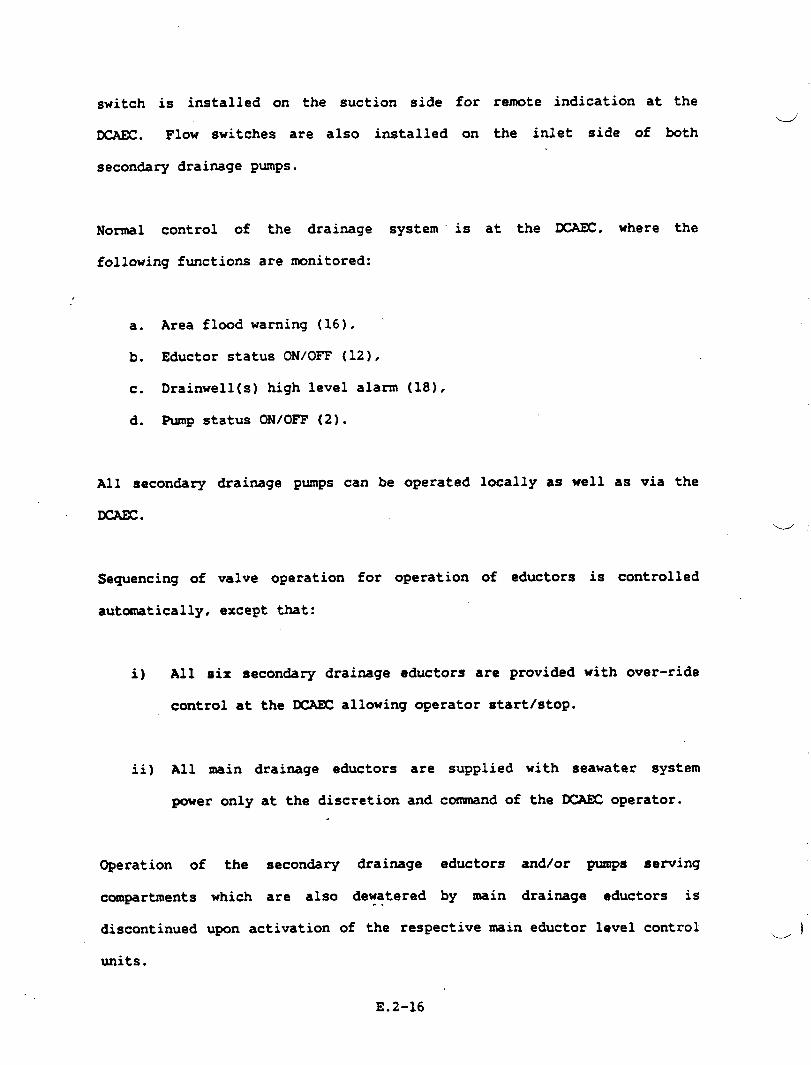
switch is installed on the suction side for remote indication at thed
XAEC. Flow switches are also installed on the inlet side of both
secondary drainage pumps.
Normal control of the drainage system is at the m. where the
following functions are monitored:
a. Area flood warning (16), ‘
b. Eductor status 01’J/0~(12),
c. Drainwell(s) high level alarm (18),
d. Pump status ON/OFF (2).
All secondary
DCAEC.
drainage pumps can be operated locally as well as via the
Sequencing of valve operation for operation of eductors
automatically, except that:
i) All six secondary drainage eductors are provided
control at the DCAEC allowing operator start/stop.
is controlled
with over-ride
ii) All main drainage eductors are supplied with seawater system
power only at the discretion and couunandof the DCAEC operator.
Operation of the secon&ry drainage eductors andlor pumps serving
c~partments which are also dewatered by -in drainage eductors is..
discontinued upon activation of the respective uain eductor level control -~
units.
E.2-16
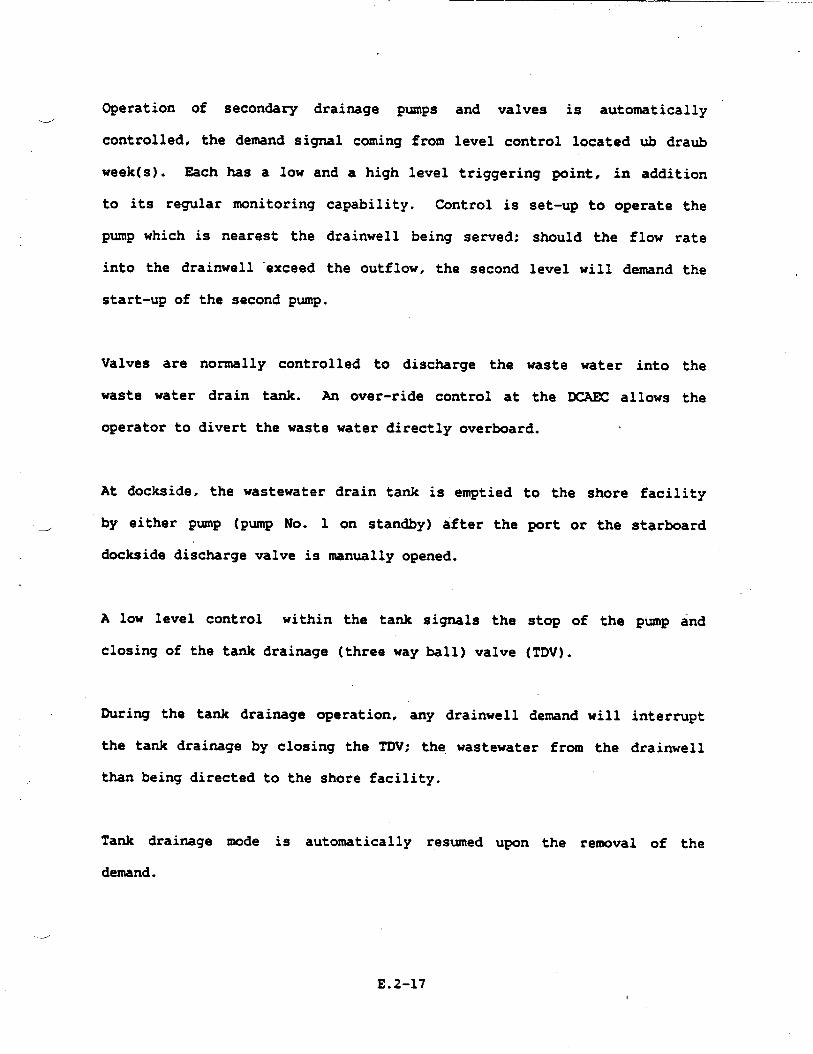
Operation of secondary drainage pumps4
controlled, the demand signal coming from
week(s). Each has a low and a high level
and valves is automatically
level control located ub draub
triggering point, in addition
to its regular monitoring capability. Control is set-up to operate the
pump which is nearest the drainwell being served; should the flow rate
into the drainwell “exceed the outflow, the second level will demand the
start-up of the second pump.
Valves are normally controlled to discharge the waste water into the
waste water drain tank. An over-ride control at the DCAEC allows the
operator to divert the waste water directly overboard.
dockside, the wastewater drain tank is emptied
either pump (pump No. 1 on standby) after the
dockside discharge valve is manually opened.
A low level control within
closing of the tank drainage
the tank signals the
(three way ball) valve
During the tank drainage operation, any drainwell
to the shore facility
port or the starboard
stop of the pump and
(TDV).
demand will interrupt
the tank drainage by closing the TDV; the wastewater from the drainwell
than being directed to the shore facility.
Tank drainage mode is automatically resumed upon the removal of the
demand.
--
E.2-17

To prevent pump operation under cavitating conditions, a the~stat is
installed at the drainwells in the propulsion engine rooms which prevents
pump start-up until the water wash temperature in the drainwell cools to
at least 100”F.
-
1_.
E.2-18

APPENDIX E.3
HVAC SYSTEM DESIGN

- .—
.
HVAC SYSTR4 DESIGN
AIR CONDITIONING SYST~
Each Air Conditioning System.
for a 3000 ton SES design contained two,
three or four independent condensing units and refrigerant circuits
located in the air conditioning fan rooms. There were four HVAC Fan
Rooms aboard the SES, two of which include an additional HVAC system
dedicated to electronic equipment cooling. Therefore, the total number
of HVAC systems was six. Each condensing unit consisted of a compressor,
condenser, condensing,water control valve, receiver, suction accumulator
and necessary
evaporator.
control devices. The unit is located below its associated
Compressor sizes are
combination to match
capacities:
System No.
1
2
3
4
5
6
approximately 2.5, 3.0, 5.0 and 7.5 tong in
loads. The six systems provide the following ~
Coding kad (Tons~
4.8
14.3
13.3
13.9
8,6*
10.9*
J
●These systems are dedicated systems for electronicequipment loads.
E.3-1
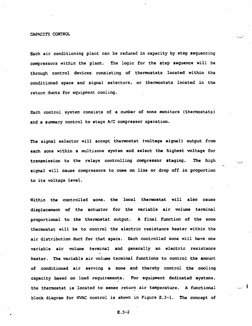
CAPACITY CONTROL
Each air conditioning plant can be reduced in capacity by step sequencing
compressors within the plant. The logic for the step sequence will be
through control devices consisting of thermostats located within the
conditioned space and signal selectors, or
return ducts for equipment cooling,
Each control system consists of a number of
and a summary control to stage A/C compressor
The signal selector
each zone within a
thermostats located in the
zone monitors (thermostats)
operation.
will accept thermostat (voltage signal) output from
multizone system and
transmission to the relays controlling
signal will cause compressors to come on
to its voltage level.
select the highest voltage for
compressor staging. The high ‘.-.’
line or drop off in proportion
Within the controlled zone, the local thermostat will also cause
displacement of
proportional to
thermostat will
air distribution
the actuator for the variable air volume terminal
the themostat output. A final function of the zone
be to control the electric resistance heater within the
duct for that space. Each controlled zone will have one
variable air volume terminal and generally an electric resistance.
heater. The variable air volume terminal functions to control the amount
of conditioned
capacity based
the themostat
air serving a zone and thereby control the cooling
on load requirements. For equipment dedicated systems,
is located to sense return air temperature. A functional 1
block diagram for ?IVACcontrol is shown in Figure E.3-1. The concept of
E.3-2
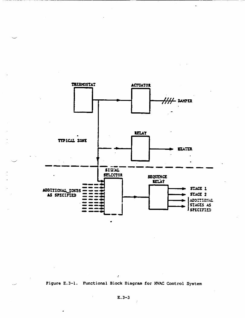
.
TYPICAL ‘km
d“
-——— — -1—.-.————,—_ __S:’r&
.
ADDlT1mU_Zori%5As SPSCIFIEB
●
——
-.
.
Figure E.3-1. Functional Block Diagram for HVAC Control System
E.3-3
h
compressor staging with reference to zone temperature is shown in
Figure E.3-2. +
AIR DISTRIBUTION
A high pressure fan is located in each air conditioning plant fan room.
The fan draws a mixture of replenishment and return air from the fan room
and forces it through a filter and cooling coil into high velocity (2000
- 4000 feet per minute) ducting. ln systems which are not equipment
dedicated, variable air volume terminals in each space admit only the
quantity of air necessary to cad the space to between 75*F and
So”r. The thermostatically controlled terminal has a preset maximum
and minimum flow rate. Minimum flow as approximately 50% of maximum
flow. Highly loaded electrical equipment spaces may be further reduced
to less than 50% to reduce reheat requirements. In”addition to cooling ‘- ‘“
flow control, the terminal contains noise absorption materials to
minimize air velocity noise. An induction feature of terminals serving ~
occupied spaces causes secondary induction of space air through the
terminal when primary air is reduced, thus maintaining nearly constant
air flow through the heater and diffuser.
Return air travels back to the fan room through passages, and in some
cases, is fan forced. Some of the air is expelled by exhaust fans
located in water closet spaces and other designated exhaust spaces.
Replenishment air from the 01 level is fed from the ventilation system to
the fan rooms. The replenishment air rate is reduced in one step to 50%
in the heating season to conserve electrical power.
E.3-4

‘.-J’
1
\ ‘-d’
ZOh%SPACE TE2SMFJRZ ‘F,S1 60 79 78 77 76 7S 74 73 72 71 70 69 68
1 1 i i I i 1 J I t b 1 i JoPna CLOSED
on~ICAL ZOXS
w
HEAT !
———— ——— ———— ———,— ——,
tM’F
I SIACE 1 [ox or?
I STAGE2 .
——— ———— —— Ti OFF
———— ——
I STACZ1 J0!{ o-
I STAGE 2. 1 UAss 3
.
‘2Eaiii!r– ”–—––––––m or?
.
i STACE 2 . .
1
———— ———— ———— ——
Figure E.3-2. Compressor Staging Concept
E.3-5

A relief or bypass damper located between the high pressure supply fan
inlet and outlet dumps air directly back to the fan room or return fan as
the terminals decrease air flow. This maintains relatively constant fan
flow to avoid instability of the fan which
design flow. The functional flow diagram for
in Figure E.3-3.
HEATING AND REHEATING
Electric duct heaters
zone. In some cases,
could occur at less than
HVAC distribution is shown
are located in the supply air duct to each space or
a separate space or radiant heater is used.
VIXTILATION SYSTEMS
Three supply fan rooms on the 01 level deliver from the weather, via
electric duct preheater, fresh air to ventilated compartments and fan
rooms of the air conditioning system.
Supply air to the medical spaces, pilot house and central control station .
include fumetight dampers in the ventilation supply ducts to preclude
possible
Mechanical
contamination from another space in case of cas~lty.
and natural supplies are used to ventilate these spaces.
The propulsion and
the combustion air
lift engine rooms ventilation is
systems. The electrical generator
considered part of
rooms and auxiliary
machinery rooms are provided with mechanical SU@Y and exhaust
ventilation systems. >]
E.3-6
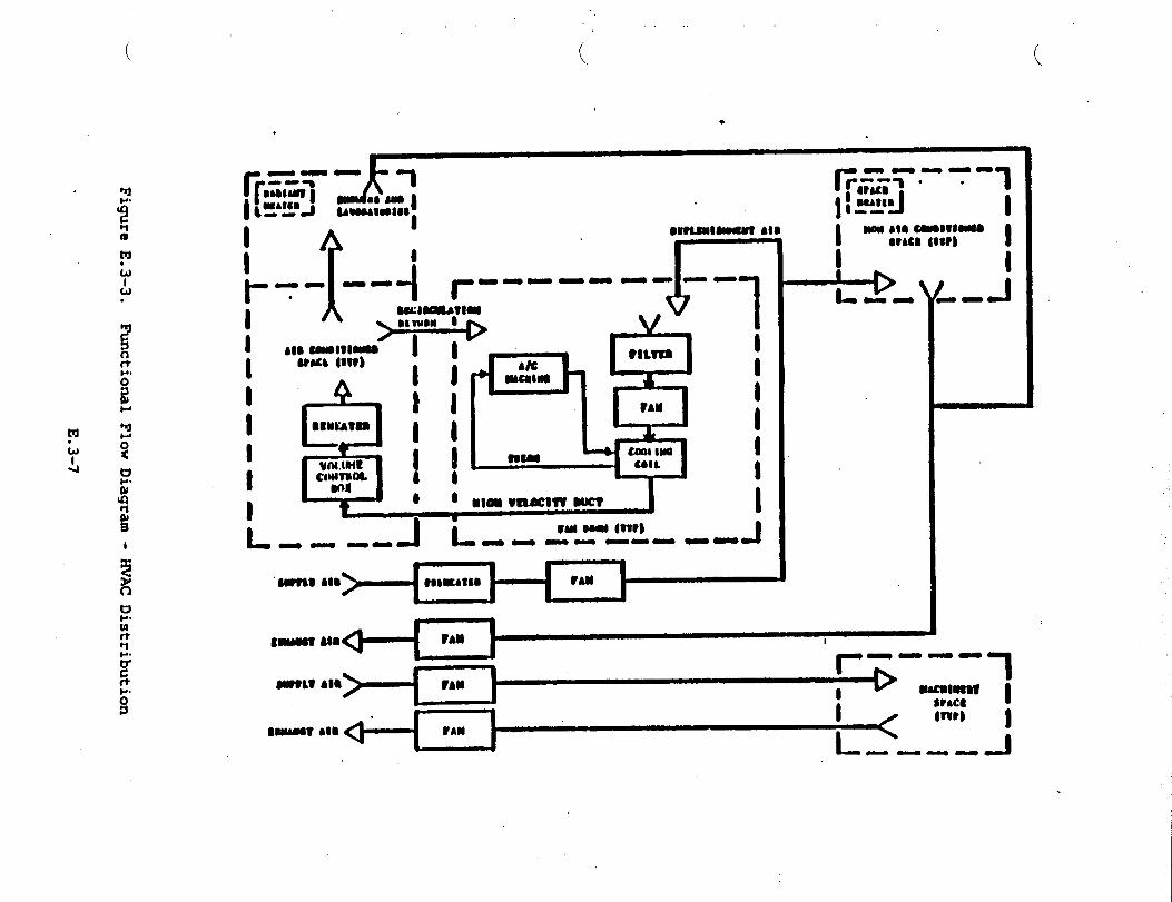
(
mLJA.
I
●
a s Bm-mlMamt AM
-J
Electric radiant heaters and mechanical exhaust to the weather are
\&’provided for all sanitary spaces.
Ventilation air flow for non-air conditioned spaces is sized to keep
maximum summer compartment temperatures or rate of change in accordance
with the requirement of the Design Criteria Manual. ~n the winter, the
ventilation rate is reduced for energy conservation, by a single
themostat sensing weather ambient air.
HEATING OF =ILATED SPACES
Spaces
air is
.Swarmer
requiring preheated air have heaters in the air supply duct. This
thermostatically controlled at 45°F (average). Spaces requiring
temperatures are provided additional duct heaters, supplemented by
space heaters
thermostats.
~/
as necessary. These space heaters are controlled by space
GENERATOR COOLING
While normal ventilation is supplied to generator rooms. a secon&ry
source of air from the combustion air intake is applied directly to the
generator enclosures. The secon&ry exhaust air becomes warmer than the
primary exhaust air. Each is exhausted via separate fans. The enclosure
exhaust is exhausted up the stack while the room is vented by normal
exhaust.
i
E.3-8
,,.
SMOKE PROPAGATIONv
In the preparation of this study, the paramount hazard related to smoke
propagation has been considered:
The propagation of smoke and possible failure of ventilation control
aboard SES maY lead to the reduction of or inability to fight the
originating fire hazard. Limited visibility and the physical effect of
smoke inhalation will seriously hamper or negate conventional
fighting techniques. As such, this study has identified means of
and fire extinguishant containment.
The application of dampers
requirements set forth inu
as recommended in
the “Ship System
‘“e
fire
smoke
this study satisfies the
Specification, T22000001C,
Para. 3.2.2.7 in regards to a method of counteracting the effects of
smoke and toxic fumes. It further fulfills the requirements of the means
of such protection by planning restrictions on the ventilation system of
the SES.
SAFETY RECOM4DJDATIONS
1. Install dampers in ducts to machinery spaces.
2. All dampers installed serving a machinery space or a space from
which machinery draws air must be provided with an interlock to
insure that the damper cannot be closed until machinery in the
space has ceased to operate.
E.3-9,

3. Under current design, the SES was not provided with an automaticu<
back-up fire extinguishing system. The incorporation of the
smoke dampers specified in this study is a provision which,
through the containment of smoke, or at least delay in smoke
propagation, allows conventional fire-fighting techniques to be
used as rapidly as persomel and equipment can be moved.
4. The build-up of residual heat in the Turbine Spaces
shut-off of the cooling fans is still being evaluated.
following
Until the
impact and amount of such residual heat is accurately determined
to be structurally safe it should be remembered that the use of
Halon as an extinguishing agent may be ineffective.
5. Should such be the case, an alternate, remotely
extinguishing system should be considered. A
actuated-. e’
technique
identified in Amphibious Assault Landing Craft Technology report,
dated Sep 1978, recoimnendsthe use of pressurized (400 psi) water
discharged as a mist. Test results indicated that a 9 ftz pan
fire was extinguished in 4 seconds with a discharge of 2 quarts
of water in a 500 cu. ft. volume space.
6. Where dampers are recommended but cannot be installed due to
weight or space considerations, the space served should be
provided with Halon flooding
rate of Halon to compensate
through doors and ducts..
and. ideally, an additional bleed
for loss of fire extinguishant
).-/
E.3-10

. . .. . ..
7.
d
a.
9.
Where grills or louvered vents are placed in doors or bulkheads
serving spaces for which dampers are recommended, the trills or.
vents should be provided with a manual closing operation that can
be controlled from either side of the grill or vents.
Where a smoke damper requirement is satisfied by a watertight
closure, the closure’s mode of operation
recommended for a smoke damper at that location.
should be that
Fume-tight dampers should be manually operated.and located, as
far as is practicable, inunediately outside the space seined.
Dampers should be secured open and so tagged under normal
conditions.
.
4 Tradeoff studies conducted during the U.S. 2K and 3KSES programs -
identified some promising subsystem design options and components as
follows:
A coamnercial 60 Hz vane compressor is now being manufactured by the
Fedders Compressor Company. The compressor is considerably lighter than
the Carrier Compressor that had been tentatively selected for SES. Vane
compressors are not internally vibration isolated like reciprocating
compressors. The latter are not suitable in applications where external
vibration or shocks are applied because excitation of the compressor
motor to the limits of the internal springs ultimately results in fatigue
-
E.3-11
cracking of the tubing connecting the compressor to the outside housing.
Only specially modified
could be used, with a
currently being used
Cincinnati is currently
compressors like the Carrier military compressor
resultant high cost. The vane compressor
in mobile applications. Welco Industries
testing 400 Hz modified vane compressors,
is
of
but
they are not as yet being marketed. The problem is higher rpm and life.
When available, these compressors should be considered. Also, the light
weight but expensive Fairchild Stratos screw compressor should be
considered.
LIGHT WEIGHT DUCTING
A major consideration in the initial design of the SES was to decrease
weight wherever possible.
One area where weight
weight, high-pressure
standard fans.
was saved on the HVAC system was the use of light
aircraft fans rather than the much heavier Navy
Weight-saving considerations were not fully explored for duct material
specifications. The initial HVAC design used the General Specifications
for Ships of the United States Navy. This general specification gives
the minimum thicknesses listed in Figure E.3-4.
These material thicknesses are for use on all surface ships. However,
most surface ship designs are not faced with the same weight saving
considerations as SES.\---i
E.3-12
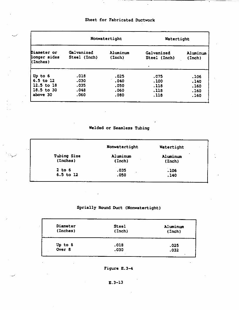
Sheet for Fabricated Ductwork
.--”
Nonwatertight Watertight
Diameter or Galvanized Aluminum Galvanized Aluminumlonger sides Steel (Inch) (Inch) Steel (Inch) (Inch)(Inches)
.
up to 6 .018 .025 ● 075 .1066.5 to 12 .030 .040 ● 100 .14012.5 to 18 .035 .050 .118 .16018.5 to 30 .048 .060 .118 .160above 30 .060 .080 .118 .160
Welded or Seamless Tubing
Nonwatertight Watertight
Tubing Size Aluminum Aluminum ‘(Inches) (Inch) (Inch)
2t06 .035 - .1066.5 to 12 .050 .140
Sprially Round Duct (Nonwatertight)
I Diameter Steel Aluminum(Inches) (Inch) (Inch)
I Up to 8 .018 .025Over 8 .030 .032
Figure E.3-4
E.3-13
In an effort to find an alternative to these specifications, the HVAC
design section investigated other types of ductwork for applicability toL/2
SES. One promising ductwork system is produced by United Sheet Metal of
Westerville, Ohio. They are specialists in spiral duct and have provided
ductwork for many U.S.
A new development at
section. ,It involved
around the spiral
shipbuilders.
United Sheet
a new process
ductwork.
representative, the added strength
Metal was of interest to the HVAC
that formed a continuous raised ridge
According to the United sales
of this ridge allows the use of
lighter weight duct. For example, if .060 aluminum ductwork is required
in a certain situation, a .050 raised ridge
strength at a weight savings of .183 lbs. per
Another opportunity
ridge flat oval
Previously, marine
for weight savings would
duct would provide the same
square foot.
be the use of spiral raised ‘-w’
ductwork in place of standard rectangular duct.
spiral ductwork was limited to round use only. The ~
new process at United would almost eliminate the need for rectangular
duct..
It should be pointed out that spiral duct is available for straight runs
only. Fittings are only available in standard weldable thicknesses.
Also, before the raised ridge duct is specified for any shipboard use,
test results must be obtained to verify that a lighter weight duct could
withstand the loads placed on it in high-pressure installations. “
‘d )
E.3-14

d Should the strength tests prove favorable, the use of this type of
ductwork would appreciably reduce the overall weight for the entire ship.
SMOKE PROPAGATION
The propagation and dispersal of smoke and noxious gases must be included
during the ventilation design phase. Final recommendations included:
a) Installing smoke dampers with interlocks in ducts to machinery
spaces;
b) Adding manual closing operations for louvers in doors and.
bulkheads.
‘v ‘Since smoke propagation and halon containment are a real concern,
recousnen&tions must be made prior to ventilation system design and
analysis.
By breaking up these ventilation syst~ into s~ller sYstem with
separate fans. crohs-comections can be eliminated. This will
chance of smoke or halon infiltration into manner spaces
shipboard fire.
MIL-STD-1472B offers much broader temperature and humidity
comfort zones and provides a more realistic approach
shipboard conditions. The summer comfort zone temperature
to 89 degrees and humidity ranges-from 10 to 90 percent,
reduce the
during a
ranges for its
to military
ranges from 67
. The winter
.
-’comfort zone temperature ranges from 66 to 83 degrees and humidity ranges
from 10 to 90 percent.
E.3-15

The boun&ries for the MIL-STD-1472B comfort zones are based on an
‘w’effective temperature (ET) scale, which shows constant physical sensation
lines. These lines give the combination of temperature and humidity
which provide the same comfort.
ASHRAE also has developed an effective temperature scale which varies
from the MIL-STD-1472B scale. Refer to ASHRAE Fundamentals Book for
further information.
-ERATURE REQUIREMENTS
The temperature requirements for air conditioned personnel spaces
(offices, berthing, wardrooms, etc.) in sumner was 80 degrees F dry
bulb/55 ‘degrees relative humidity, and in winter was 70 degrees F dryU’
bulb/no R.H. requirement. These were the standards from which the HVAC “-
calculations were developed. If it was possible to use more realistic
requirements,
appreciably.
equipment with
HEATING SEASON
The original U.S.
on surface ships
the heating and cooling loads might be reduced “
The lower loads would allow for smaller or less HVAC
a considerable.conservation of energy and wright.
Navy temperature
was 65 degrees F
requirement for
dry bulb. That
air conditioned spaces
temperature was raised
to 70 degrees in OPNAVINST 9330.7A, U.S. Navy Shipboard Habitability
Design Stan&rd. This stantird also includes the provision that.
appropriate tradeoffs be conducted to derive habitability features most‘.-.-)
responsive to mission requirements.
E.3-16 ,
.
In the case of the SES. a tradeoff study
dwhether lowering the design temperature in
F dry bulb will have an effect on
t
should be made
berthing spaces
reducing the
requirements. The lower design temperature
comfortable for sleeping, since metabolism for
half that of light office work.
to determine
to 65 degrees
heating load
would probably be more
sleeping is approximately
Making a rough preliminary estimate, it was determined that lowering the
design temperature of berthing spaces from 70 to 65 degrees would reduce
the KW required for
considerable savings
many heaters, thereby
heating those spaces by approximately 10 percent, a
of energy. This savings would reduce the size of
saving weight.
-COOLING SEASON‘d
?
The cooling season requirements for most air conditioning s~ces
(offices, berthing, etc.) on the SES is 80 degrees D.B.tS5 percent R.H.
This design temperature condition, when plotted on the cooling season
psych chart gives
below the 75 degree
To analyze the air
an effective temperature reading of 74 degrees ET.
ET upper boundary of the summer comfort zone.
conditioning systems, each system room mix temperature
and relative humidity could be plotted on the psych chart to determine
the effective temperature for the system. The results of this analysis
are as follows:.
d
E.3-17

Room MixA/C System Temperature
Effective ‘Temperature
1 80.4°2 82.6°3 82.6°4 80.0°5 85.0°6 85.0°
72°74.5°74.7°72°76”76°
AS shown above, all but two systems (n~ers 5 and 6) have an effectives
temperature under 75 degrees and as such are within the MIL-STD-1472B
sumer comfort zone.
Since nine of the AiC systems have room mix temperatures under the upper
boun&ry of the comfort zone, there is an opportunity for energy savings
if the room mix temperature were allowed to increase to the upper limit.
HEAT PUMPS\-.,
The ultimate HVAC system
requirements for personnel
the ship at minimum weight
for an SES is one which meets all of the
health and safety and the combat readiness of
and maximum energy efficiency.
Such a system requires a departure from traditional and Navy standards of
design, equipment and materials. From preliminary studies, a water
source heat pump offers promise of providing the ultimate system. The
heat pump has become, in recent years, one of the outstandingly energy
efficient devices for controlling an interior environment. In the
comonly known heat pump, heat is removed from a space and rejected to
the outside by the standard vapor cycle refrigeration system. By
reversing the cycle. heat is extracted from the outside and rejected to )
E.3-18

the space. In the water source heat pump, the outside is replaced by ad
circulating water supply which serves as a rejection medium or the source
of heat, depending on the mode of operation of the heat pump. The
circulating water system is provided with means for cooling or.heating as
required to maintain the circulating temperature within limits which will
produce efficient space heating and cooling.
Customarily, heat pumps are applied to a complex structure in small
unitary -chines served by a single water system. It can be seen that by
this means heat can be removed from one portion of a structure and added
to another part if required.
For the SES, as applied to
‘compartmentation. individual..#
other structure
heat pump units
of similar complexity and
would be installed within
the space being controlled and would require little or no
exception might be a series of contiguous spaces, such as
having similar environmental requirements, where one heat
several spaces with interconnecting ducts.
duct work. h
berthing areas
P- may serve
The advantages offered by this system is weight, efficiency and space
saving are as follows:
1. The duct work
80%, partially
required may be reduced in weight by as much as
by reduced size and primarily by elimination.
2. The weight and complexity of electric duct heaters is eliminated
entirely along with the wiring and controls..
E.3-19
3.
4.
5.
6.
7.
8.
9.
10.
Electrical load is drastically reduced for heating since heat
pumps provide approximately three times the heat of resistance
heaters per watt.
Fuel consumption for electric generation is reduced.
Waster heat from the exhaust of the electric generators is added
to the circulating Water system to provide space heating.
Simultaneous heating and cooling of any space is eliminated
saving energy and fuel.
Fan rooms for HVAC are eliminated.
Controls become simple heating/cooling the-stats. reducing
system complexity.
Reliability is enhanced since each heat pump is an individual
system. The failure of a heat pump will only affect the area
served and not affect the operation of the balances of the system.--
Infinite zoning is possible for special temperature requirements.
The disadvantages are:
1. Additional ventilation ducting would be required since
replenishment air must be piped to each heat pump. However. these
are small ducts and do not add significantly to the system weight.
2. Piping would be increased by the circulating system. Such pipes
are light weight fiberglass and do not require insulation.
3. A means of heat rejection and a waste heat boiler would be
required adding to system weight.
“i._.’
4. Condensate drainage problems ~uld be cqlicated by the n@er
and dispersion of the evaporators. ../
E.3-20

Water source heatu
available from a
pumps have been marketed for over 20 years, and are
number of suppliers. However, no information is
available as to their compatibility with the marine environment.
PROPULSION _UST DUCTS
In the current ship
are located in the
configuration, the outboard propulsion exhaust ducts
upper level of the 2and deck aft, both port and .
starboard. The extremely high temperatures in the exhaust ducts require
that the pump rooms each have their ‘ownventilation system.
The solution to this design problem is to locate the propulsion exhaust
ducts outside the watertight boundary of the ship,
‘watertight deck directly under the exhaustd
and providing grating above and outboard of
ducts at the
the ducts.
by locating a
2and deck level,..
,
The propulsion
air, and would
exhaust ducts
not require a
would then be cooled by exposure to outside
separate ventilation system.
The drawback of this proposed solution is that a sizeable portion of the
flight deck would be made of some type of grating, with reduced
structural strength. A structural analysis would be required to
determine whether additional structural members were necessary..
VORTEC COOLING SYST~ .
.
In reviewing the problem of backup cooling for vital equipment, the.
d
VORTEC cooling system was ‘investigated.
E.3-21
The VORTEC enclosure cooling system
Cincinnati is a product which converts
one hot and one cold. The cold air
sold by VORTEC Corporation of
wcompressed air into two streams,
is directed into the electrical
enclosures, replacing the heated enclosure air which is induced and
vented outside with the hot exhaust of the vortex tube. The product can
be used continuously, or with a thermostat
The entire cooling system uses 25 CFM
for intermittent usage.
at 100 psi inlet pressure.
Refrigeration is generated at the rate of 1500 BTUtHr or 440 watts when
running continuously.
As can be seen from the above figures, these
partial solution to equipment
backup system in the event
cooling for the A/C system.
As stated above, this system
lines. Also a route must be
the outside.
cooling. However,
products offer only a
they might be used as a
of A/C system’ failure, or as preliminary.- W
requires connection to
found for the exhaust
the ship senice air
from this system to
E.3-22

.-———
APPENDIX E.4
FRESH WATER SYSTEMS
w
.-/’
For the distillation plant, three options were considered:d
a. An electrically heated vacuum distiller
b. A vacuum
heat,
c. A reverse
The electronics
distiller which used the turbine engine exhaust waste
osmosis process
cooling,. ~table and fresh water and auxiliary fresh
t!
water cooling systems adhere
alternatives were considers;
primarily to offer a weight or
to stan&rd Navy practice and no system
however, some variations were considered
water savings. As an example, Table E.4-1
outlines
1.75 GPM
.4
several showerhead options. The Low Flow Showerhead which uses
was selected for the system.
.
The results of trade-off studies performed in the distiller area have
lead to selection of a commercial, electrically heated, vacuum
distillation unit. The reverse osmosis unit, even though advances have
been made in membranes suitable for sea water use, was eliminated because
no commercial unit specifically packaged for shipboard service was
available. This process, however offers long tern potential because of
modest installed weight and minimal operating power requirements.
Utilization of turbine exhaust waste heat was eliminated on the basis of
convenient packing of water heating coils around the GTG exhaust ducts.
and because of somewhat higher overall weight than the vacuum still.
.-/
E.4-1

Table E.4-1. Showerheads Comparison
OPTION WATER USAGE RATE (HOT & COLD)
kan&rd Showerheads 2 gpm min. at 5 psig min. per GEN SPECS5 gpm at 12 psig per conunercialstandards2.5 gpmper MIL-S-9555.3 gpm per DD 938
OW-F1OW Showerheads Approximately 1.75 gpmInstallation is simple
Minuse” System Showerheads 0.5 or 0.7 gpm depending on nozzle designMinuse System, Inc. chosen.~ackson,CA)
Electrical power required for operation.
Pressure required is 35 to 125 psig. .
Highest cost of all.
lSRDCHandheld Unit 0.75 gpm, this system requires the userto push a button to maintain water flow.
)-2
E.4-2

,
DISTILLING PLANT.-.-”
The distillation units (2) selected are of the vapor compression type
(the--compression ). The units are self-contained “package type”. The
units are designed for automatic operation, and is suited to remote start
and monitoring.
Each unit will produce,
gallons per 24 hours of
will produce distillate
without descaling or cleaning, an average of 2400
operation over a period of 10 days. The plant
from sea water of not less than 1.32 density (32
pounds of sea water containing one point of dissolved salts) and at
temperatures between 28° and 85°F. The product water will have a
salinity
(ePm)‘or4
The unit
content not exceeding 0.0325 equivalent per million ‘of chlorides
0.125 grains of sea salts per gallon (gpg).,,
operates on input power sources as follows:
a. 440 V, 3-phase, 400 Hz for all pump motors, electric heaters, and
compressor motors.
b. 28 V, direct current for control circuitry.
c. 110 V, l-phase, 400 Hz for operation of the salinity indicating
system.
The unit incorporates a suitable system for locally monitoring distillate
purity by means of a relay meter calibrated in microhmslcm, with
automatic correction to 77°F. The meter will provide
point relay contacts for local audible andd
contact rating for additional remote alarms
E.4-3
visual alarms
and controls.
adjustable set
with sufficient
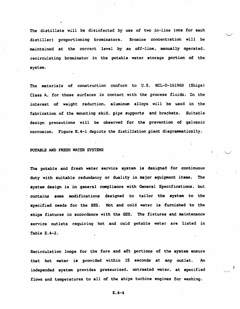
,
The distillate will be disinfected by use of two in-line (one
distiller) proportioning brominators. Bromine concentration
for each
will be
maintained at the correct level by an off-line, manually operated,
recirculating brominator in the potable water storage portion
system.
The materials of construction conform to U.S. MIL-D-16196D
Class A, for those surfaces in contact with the process fluids.
interest of weight reduction, aluminum alloys will be used
of the
(Ships)
In the
in the
fabrication of the mounting skid, pipe supports and brackets. Suitable
design precautions will be observed for the prevention of galvanic
corrosion.
POTABLE MD
The potable
Figure E.4-I depicts
FRESHWATER sysm14S
the distillation plant diagrammatically.
.- ‘.-J’
and fresh water service system is designed for continuous
duty with suitable redundancy or duality in major equipment items. The
system design is in general compliance with General Specifications, but
contains some modifications designed to tailor the system to the
specified needs for the SES. Hot and cold water is furnished to the
ships fixtures in accordance with the GSS. The fixtures
service outlets requiring hot and cold potable water
Table E.4-2.
Recirculation loops
that hot water is
for the fore and aft portions of the
provided within 15 secon& at any
and maintenance
are listed in
independed system provides pressurized. untreated water,
flows and temperatures to all of the ships turbine engines
E.4-4
system ensure
outlet. An
at specified )L/
for washing.
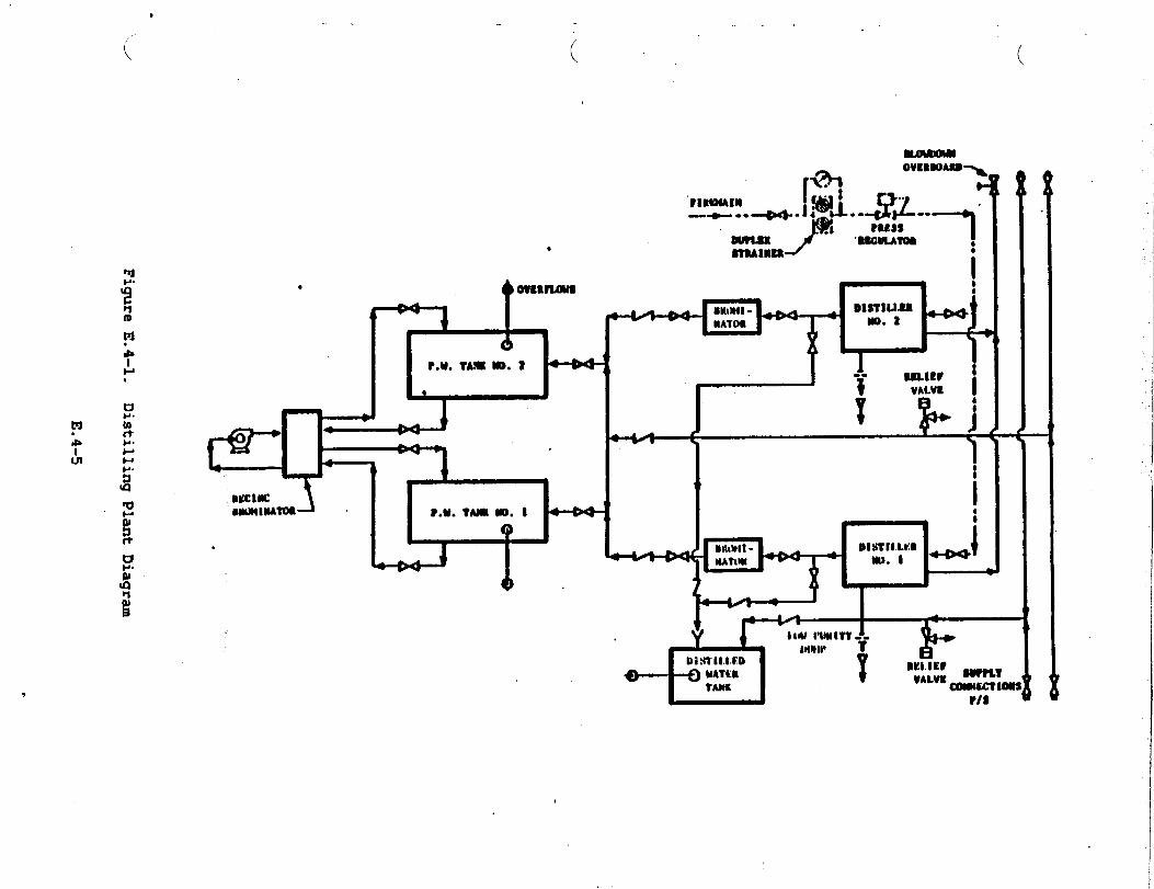
..
..
.——z
.-.--’
● Lr.
-J
.
FigureE.4-1.
DistillingPlantDiagram
E.4-5
.
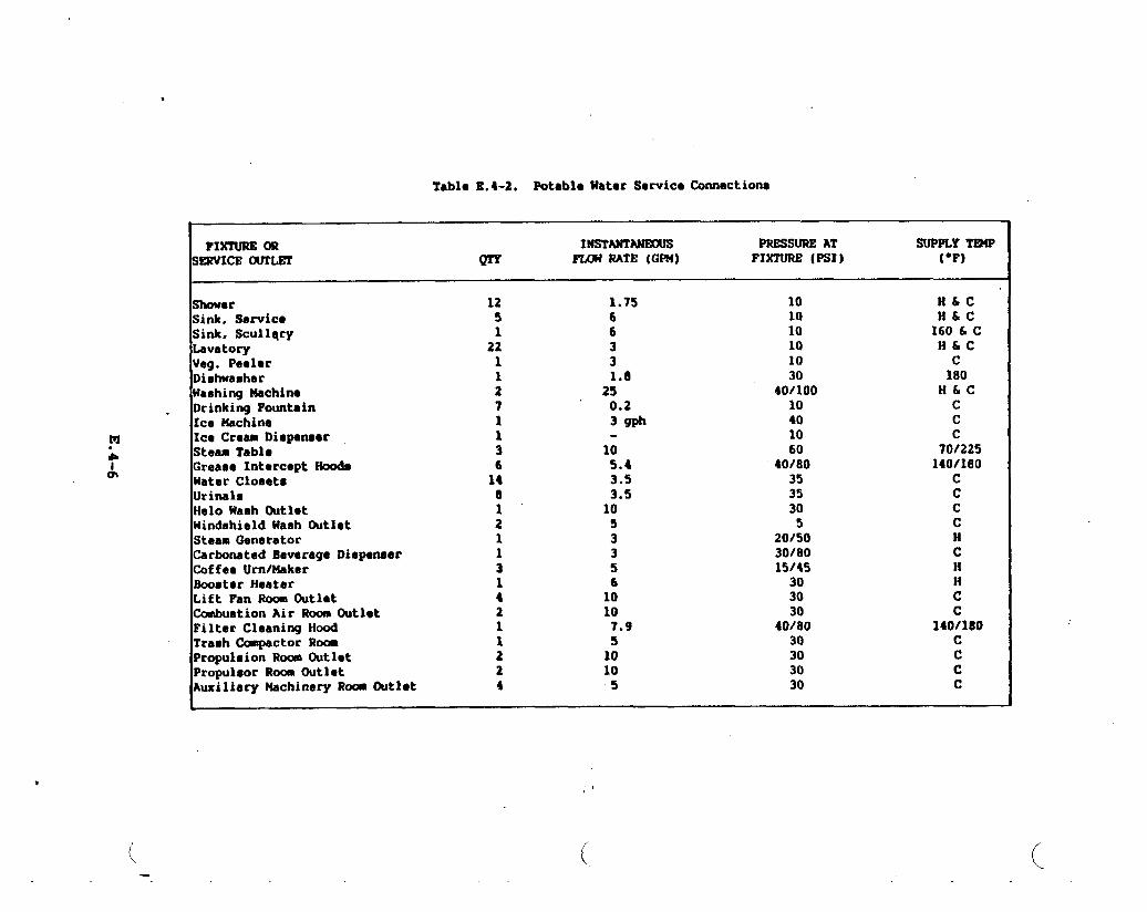
TablaE.4-2. PotableWaterServicaconnections
&
FIXTUREOR INSTANTANEOUS PRESSUREAT suPPLYTmPSE3ZVICE(XJTLST m -MTE (GR4) FIXTURE(PSI) (‘F)
ShouorSink, ServicoSink,ScullqryLavatoryVeg.PeelerDishwasherHashingMachirm
Drinking FountainIce UachineIceCreamDispeneerSteamTabloGreaseInterceptModeWaterClosetsUrinalsHeloWaehOutletWindshieldWashDutletSteanGeneratorCarbonatedBeverageDiepeneerCoffaeUrn/MakerSoosterHeatarLiftFan RoomOutletCombustionAirRoomOutletFilterCleaningHoodTraeh(hpactor RoamPropulsionRoomOutletPropulsorRoomOutletAuxiliaryMachineryRaomOutlet
125122112711361481“211314211224
1.7566331.8250.23*
105.43.53.5105335610107.9510105
101010101030
40/10010401060
40/803535305
20/503018015/45303030
40/8030303030
H&CH&c160SCH&Cc180H&cccc
70/225140/180
ccccHcHHcc
140/180cccc
(
,,
(.

..?, –.,4
.,.
Provision is
4 specified by
Figure E.4-2
made for proportioning detergents into the wash water, as
the turbine manufacturers.
illustrates the potable and fresh water service system.
ELECTRONIC COOLING WATER SYSTR4
The electronic cooling water system delivers 59°F fresh water to
electronic units. The system is comprised of standard package type water
chiller, with an electrically powered compressor and a sea water cooled
condenser. distribution piping {essentially ~), two pqs, flow
balancing valves,
instrumentation of
-depicts the systemId
expansion tank and pressure, temperature and flow
both local and
schematically.
remote indication type. Figure E.4-3
r
AUXILIARY FRESH WATER COOLING
The system design is based on the system described in Navy Mechanical
Standards Drawing No. 803-225-1137 entitled “Electronics Cooling Water
System”. A standby heat exchanger is not included in the system design.
The system, constructed essentially of CRES, provides demineralized water
at 105°F and the purity specified in MIL-STD-11399; which is a standard
governing cooling water to be used in support of electronic equipment..
The system is initially charged with water of this quality and is
maintained at this level of purity by a demineralize located in a bypass
loop of the system. The bypass loop is sized at 5 percent of the total.
system flow. Figure’E.44 depicts, schematically, the system elements.u
E.4-7
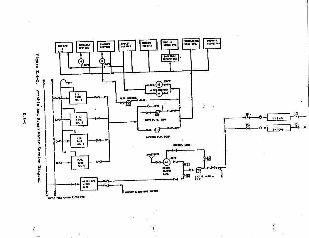
1i
&T
r
+
6?Eil
“r-?Iie
T.—
~—
--——
-.-—
.-,--
--
“
FigureE.
4-2.PotableandFreshWaterSewice
Diagram
E.4-8
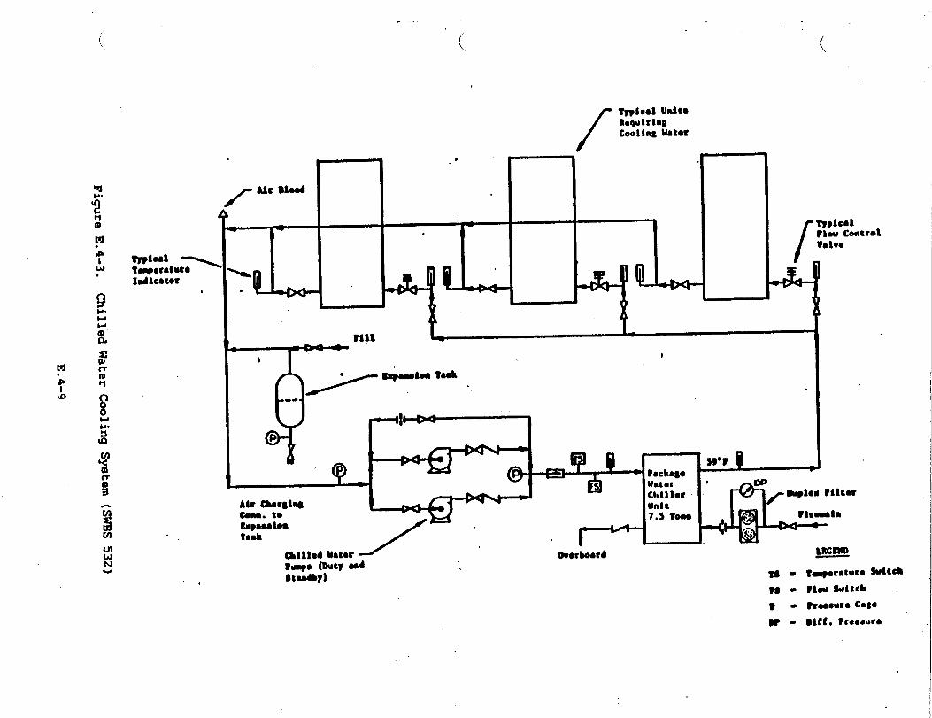
.
1
.
‘d.
.
/.
19
:.1
.\
4
.
Fi~re
E.4-3.
ChilledWaterCoolingSystem
(SW’BS532)
...4
E.
4-9
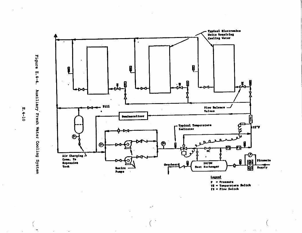
‘Ud
+
GA
.
●bao
T
--#R’
<
d
t1
FigureE.4-4.
Auxiliary”Fresh
E.4-10
Watertiling
System
,L“

,,,
d“
‘e -
APPENDIX E.5
PUEL SYSTEMS
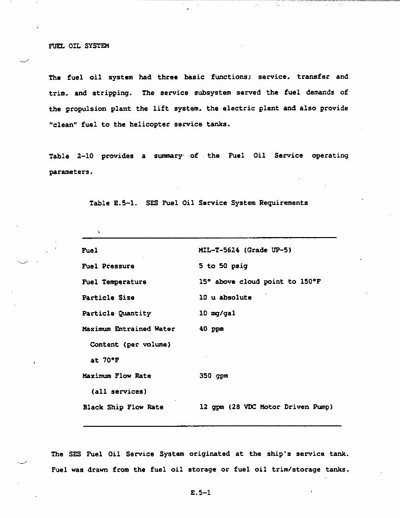
.
FUEL OIL SYST~
J
The fuel oil system had three basic functions; service ● transfer and
trim, and stripping. The service subsystem served the fuel demands of
the propulsion plant the lift system, the electric plant and also provide
“clean” fuel to the helicopter service tanks.
Table 2-10 provides a summary- of the Fuel Oil Service operating
parameters.
Table E.5-1. SES Fuel Oil Service System Requirements
a
Fuel
fiel Pressure
Fuel Temperature
Particle Size
Particle Quantity
Maximum Entrained Water
Content (per volume)
at 70°F
Maximum Flow Rate
(all services)
Black Ship Flow Rate
MIL-T-5624 (Grade UP-51
5 to 50 psig
15” almve cloud point to 150”F
10 u absolute “
10 mglgal
40 ppm
350 gpm
12 gpm (28 VDC Motor Driven Pump)
The SESd
Fuel was
Fuel Oil Service System originated at the ship’s service tank.
drawn from the fuel oil storage or fuel oil trimistorage tanks,
E.5-1 I

processed through a set of duplex filter separators and transferred to
the dedicated Fuel Oil Se-ice tanks. When the fuel oil is delivered to
these tanks, it is no longer available for trimming, thereby reducing air.
and water contamination. The fuel oil service subsystem took suction on
the service tanks,
fuel again before
engines. The Fuel
and a second set of
delivering it to the
Oil Service System is
filter separators processed the
propulsion. lift and electrical
divided into port and starboard
distribution systems. Each systein incorporated dedicated pumping,
filtering,
starboard
Components
● Two
● TWO
● Two
● Two
and flow control components. By cross-connecting the
and port systems, complete redundancy is afforded the SES.
included are:
service tanks
service manifolds
prefilter-filterlseparators
sezwice pumps
● Vents and overflows
● Liquid level indicators
● Damage control valving
● F1OW control valves
The heart of the service system is its distribution center or fuel oil
service manifolds. The manifolds are designed to integrate into one
unit; a high flow (350 gpm) centrifugal aircraft p-, a low flow (12
gpm) centrifugal pump, and cartridge type isolation valves.
The high flow service pump is for normal
flow pump will be used for “start-up” and
E.5-2
operating conditions, the low 1w
black ship operation. The high
.

,..
flow service pump is driven by a 400 VAC - 30 - 60 Hz electric motor, the
dlow flow pump is powered by a 28 WC electric motor.
The concept behind -nifolding the service
weight, eliminate tubing joints, and provide a
The filter-separators conform to MIL-F-15618
components is to reduce
local center of control.
and are designed for 350
gpm, 10 u absolute particle size, and 40 ppm entrained HzO at 70°F.
The units are designed with a prefiltering stage to eliminate particulate
contamination at the filtering elements thus maintaining high performance
and long life.
The trim and transfer system receives the ship fuel from the refueling
-stations and distribute it to-d
trimistorage tanks. The system
manifolds, for trim and transfer.
psi. The transfer system supplies
the fuel oil storage and fuel oil
incorporates 2 pumping stations or
Each has a capacity of 350 gpm at 80
fuel to the service tank through a set
of duplex filter separators
system route fuel to and from
storage tanks, to adjtit the
operating profile.
similar to the service system. The trim
the trim/storage tanks, and if required the
craft center of gravity as required by the
The
the
was
The
transfer and trim manifolds were designed with
semice manifold, and incorporated similar
obtained by pairing the trim manifold with
distribution system was symmetrical about the
the same basic idea of
components. Redundancy
the transfer manifold.
centerline of the ship,.
thereby providing equal pressure drop and an even fueling rate duringu
E.5-3

refueling operations. The transfer and trim system consisted of the
following components:
Transfer System
● One
● One
● One
● One
fuel oil storage tank
transfer nanifolds
350 gpm, 80 psi. 440 VAC - 30 - 400 Hz centrifugal pump’
duplex filter/separators per MIL-F-15618
● Damage control valves
● Vents and overflows
● Liguid level indicators
Trim System
● Four trim-storage tanks
● One trim manifolds
● One 350 gpm, 80 psi, 440 VAC - 30-400 Hz, centrifugal pump
● Damage control valves
A stripping subsystem was incorporated into the overall fuel oil system
to remove water
processed to the.
transferred from
contamimtion. Contaminated fuel oil is collected
Contaminated Fuel TanJc (CFT). The contaminate is
the CIT to a dedicated contaminated fuel holding
and
then
tank
(CFHT), and retained here until discharge to a proper facility is
u“
available. The stripping system is independent of the fuel oil system
and served all fuel oil tanks..--”
E.5-4
.—
The stripping system consisted of:/
d
● Two stripping awmifolds
● Two centrifugal ZOOgpm, 50 psi, 400 VAC - 30 - 400 Hz
electric motor driven pumps
Refueling and defueling operations are performed at refueling at sea
stations (RAS). The fueling replenishment at sea equipment
located and installed in agreement with U.S. Navy Document
requirements of fuel replenishment at sea are defined as
replenishment, at a maximum of 3,000 gpm using U.S.
equipment.” The requirement of 3,000 gallons per minute
rate was satisfied through transfer stations (7” hose,
‘receiver) port and starboard. The receiving” stationJ
was designed,
NWP 38D. The
“side by side
Navy standard
replenishment
single proble
included the
required equipment to handle the 300 foot heavy weather rig. Dockside
fueling of the craft was performed through the same fueling equipment
used for underway fueling.
The design of the controls for the fuel system was based on a combination
of manual and automatic control. All valves were electrically (24VDC)
operated with manual redundancy and position indicators. The use of the
functional manifolds allows the controls to be set to any function
(alignment of the system) and powering the system to achieve
predetermined tank levels.
Fuel control functions were performed manually and electrically. At each
1 manifold, a centralized electric control station and a local control
station was provided. The display was: (a) digital and warning light for
E.5-5

the fuel level, (b)
(selector switch),
lights for pumps,
fuel temperature
indicator for fuel
and (g) readout for
digital and warning light
(c) warning lights for
filter, filter coalescer,
for the pressure indicators
filter P, (d) functional
(e) digital indicator for
at service tanks (selector switch), (f) digital
temperature at engine inlet (engine instrumentation).
strapped-on flow meter (selector switch).
Puel systems design integration was
where all the functions of the system
except the helicopter fueling functions
Through fuel management. the proper
represented by the central control
are monitored and all the functions
controlled for
central control
fuel management
the best attitude and
are controlled.
ship center
performance
together with the monitoring devices
possible.
AVIATION FUEL SYSTEMS (JP-5)
of gravity can be
of the craft. The
and in&ruments make‘.-J
The aviation fuel system (JP-5) was designed and engineered
with Section 542 of the GSS. The JP-5 Aviation Fuel System
service tanks is an independent system in its operation and
tanks are filled from the SES JP-5 service tanks
in accordance *
from the JP-5
control. The
through the
prefilter-filterlseparator uriitsof the SES fuel system service subsystem..
The JP-5 system included a manifold that integrated the fuel pumps and
valves (identical to the one of the SES D~ Fuel Oil System), electric
motor operated valves, a filterlseparator~ and a control station just VI
below main deck level that included the hose reel for inflight refueling
E.5-6
and connections
Since the pumping
pressure increase
for deck fueling, defueling and fuel recirculation.
equipment was of the centrifugal type, the differential
during inflight refueling reduced the flow capability
to 150 gpm.
NATERIALS
The Fuel Oil System on the SES has the advantage of being compatible with
existing aircraft materials and components. Except for the large size
components and filters, aircraft
potential.
Tubing is a corrosion resistant
4 ccmmonly known as 21-6-9 CRES or
strength alloy allowed the use of
reliability
safety. The
A survey of
improved the
resistance to
system
hardware was utilized to its maximum
steel of high strength per ANS 5561,
ARMCO Nitronic 40. This high tensile
thin wall tubing that together with the
installation with a large margin of
corrosion is compatible with-CRES 3161.
the market indicated that the fuel valves as used in aircraft
fuel systems were suitable and compatible with all the conditions. The
only modification required was the change of the aluminum alloy butterfly
disc to stainless steel to increase the pressure rating of the valves.
All valves incorporated thermal relief.
4“
E.5-7

.--’
APPENDIX E.6
COMPRESSED AIR AND NITROG~ SYSTEMS
‘../
d“

STARTING AIR SW- REQUIREMENTS
J
The system requirements for the 3KSES were established by the ~9
(propulsion engine) and W2500 (lift engine) starters, propulsor
(waterjet) priming and engine motoring (wash). Table E.6-1 summarizes
these requirements.
Table E.6-1
Starting Air System Requirements
FLCm, PRESSURE, TEMP..
SYslm! DUTY
->
MS/MIN PSIA (MIN) “F (MAX) AVAILABILITY
\ Start Aird
Start LM2500 194 49.7
Prime Propulsor 116 59
Wash IA42500 119 40
.
450
425 Intermittent●
200
HI@i PRESSURE COMPRESSED AIR REQUIREMENTS
MK32 torpedo tubes launch system required 1500 psig charged flasks (900
cu. in.) for torpedo launching. In addition, 250 psig for the VU is.
required. This was an intermittent service.
----’”
E.6-1
SERVICE AIR SYSTEM REQUIREMENTS
w“
The service air provided uninterrupted service to vital systems by the
use of a priority valve. Dry air was provided for wave guide
pressurization and other equipment as rewired. Regenerative type
desicant dehydrator was used to assure air quality per MIL-D-23523 for
Type 11 dehydrators. Outlets for non-vital services were fitted with
in-line filter, regulators and gauges as re~ired. Table E.6-2 provides
a summary of service air requirements.
NITROGEN SYSTEM REQUIREMINTS
Nitrogen Systdn
accordance with
provided oil-free nitrogen at 4 to 3000 psig in
Federal Specification BB-N411. . Type 1. Grade A, .
Class X. Distribution and outlet discharge pressures of nitrogen - “
stations satisfied those requirements of NAVAIR Bulletin lC to accomplish
certification.
Nitrogen System
SYST~ DESIGN
System denan~ for nitrogen is provided in Table E.6-3, “
Requirements.
The Start Air System is shown in Figure E.6-1. The source of start air
was three load compressors driven by 3 diesel generator sets. Each DGS
drove one load compressor as required. The load compressors could be
de-clutched when not required. One load compressor was capable of
starting one propulsion engine at a time or one lift engine at a time.
The propulsion engines could also be started by cross bleeding, one at a
E.6-2
w

..
(... .
t?N!SS, DRY AIR?IWAL?UW ~~lc — ?lLm
ltm Vs8 WCA?IOH Scr?t yes m RxqulRf!D mwxs
pottMaw.Ouidc Opar.-(radar) Sadar xOo,l-l- 10 80 Dew Pt ● br$oncy
●
to +60”F Yes
--—+20V
Air Dtlvon Intensltier tot xen#w?Ma Deek 30 100. x Ltno Int.rmittmt
)lltroaen SY9 halo ●orv} ?lltsr
5* Shop Air, Ho~oCoanactio- 12 placosl &x Heck Som 3, 40-s0 20-100 X Lino IntormittcatOaa Roou, Armory,LtCt ?an riltorBu, Rofris Mcb WxmBlec Neint.. Aviac L Cen.Uork Shop. isltcr Clesnhm
6. RoacuoSoaturt lbh DackAtt hm-’52 M (2 co 90 Iti Int.rdtt.nto9 ●in.) rnraency
Aux.?reeh Water Coollna Sya Aux. Uech. Sooa 11 w flou so-so x MO Intermittcntt●
(coaproaslontmk chert ins) once a dey8. Th.rmmtac Control About60 nl@rBo6tats lU&LblmJ 2a-2s x w Continuous
9. Valve ~sration, DistlllarM ~~ ●nd #~ 1O-2O 100 EM Intermlttont
onc9 ● daq
12. Suffer Air (~h) tropuleionEnaha Room 180 so XMO Intormittont13,
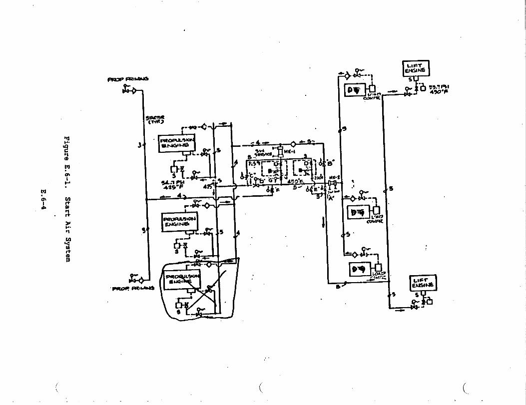
.
.
.
-.L
/”.
..
I
lb
FigureE.6-1.
StartAirSystem
E.
6-4
..
‘u

.
Table E.6-3
-/Nitrogen System Requirements
*Semite
Tires
Landing Gear Struts
~ergency Gear Extension
Rotor Blade Fold Accumulator
Auxiliary Flotation Cylinders
Tailwheel Centering Cylinders
Rotor Blade Inspection
* (15-50 SCIM)
Pressure, PSIG
75 - 250
1500
3000
1500
3000
425
4-16
time. During cross-bleed start, the propulsion turbine bleed air is to
be routed via a heat exchanger and reducing valves to lower the
temperature and pressure to the turbine-starter requirements in
accordance with nmwfacturer’s requirements.
.
The control and monitoring of the start air system is from ~ and
monitorincjis also accomplished at the XAEC Panel. In an emergency, the
start air system can also be controlled at the LOP.
A detailed tradeoff study and analysis was made to evaluate the best
method of starting the propulsion and lift engines. s This study was made
on the basis of least weight and cost in meeting performance
requirements. It was ascertained that the load compressors driven by—,
E.6-5
,diesel generator sets was the method to be adopted. A weight efficient
SES would delete existing cross-bleed due to triple starting redmdancy,
thereby reducing system weight and cost.
“L#’
The start air system as shown in Figure E.6-1 performs the following
functions:
o Start propulsion engines, one at a time, using air
compressor.
o Start lift fan engines, one at a
compressor.
o Start propulsion engines, one at a
reduced bleed air from an operating
time, using air
>
time, using cooled
propulsion engine.
from a load
from a load
and pressure
‘u
o Provide air for propulsor priming from a load compressor.
o Provide air for propulsor priming using cooled bleed air from an
operating propulsion engine.
o Provide buffer air during propulsion engine starter motoring for
engine water wash using cooled air from a load compressor.
.
All piping, fittings. valves (including solenoid valves), heat ●xchangers
and components are to be of stainless steel since this system was
required to withstand 104*F intermittently. which produces very high
piping thermal stresses.
E.6-6
‘.-/’
The lightweight stainless steel system, with thermal expansion joints and
2 bends, meets the overall weight and displacement objective as well as
performance requirements of the system.
HIGH PRESSURE COMPRESSED AIR SYST~.
The high pressure compressed air system is a 3000 psig system with two
1500 psig branches for torpedo
charging one flask (900 cu. in.)
CRES piping and deliveries c~ean
charing stations.
charging. This system is capable of
in about 6 minutes. The system used
(S0 microns), dry air to the torpedo
A multi-stage high pressure compressor feeds into a half cubic foot
separator flask and then into an air dyer and purifier unit. The system
-. is then divided into port and starboard branches (3/8” CRES piping). -
Each branch containing four cubic foot flask charged to 3000 psig and
terminating in a torpedo charging station including an air filter, a
needle valve, a pressure reducing valve and a pressure relief valve.
SHIP SERVICE AIR SYS=
The Ship Service Air
source of air was two
System is in accor&nce
air compressors each with
with Figure E.6-2. The
discharging at 125 psig
and 11O”F (-x). One air- compressor is capable of servicing the whole
ships service air requirements. The other air compressor is for =
standby. The compressors are hooked up electrically so that on low
pressure in the receiver tank (11O psig). the compressor would
‘uautomatically cut-in; and cut-ut at 125 psig. In case of failure of one
E.6-7

.-
-b.
1
‘o●
i8:m,1
l-l
.s
T
.
,
w
.
3_
FigureE.6-2.
ShipServiceAirSystem
E.6-8
1’
‘.-.’

..-/”
‘.--’
.-”
*
compressor, the otheq compressor would automatically cut-in. The air is
filtered and dried before delivery to various service points throughout
the ship. The control of these compressors would be located on the DCAE%
panel as well as locally. Monitoring
The air supply was divided into two
is also done at both
systems, vital and
vital supply via a regenerative dryer fed wave guides
equipment. The non-vital could be” closed off by a
priority valve.
locations.
non-vital. The
and electronic
motor operated
Two independent dedicated low pressure air compressors are used on the
SES to support the ship service air requirements. Ml piping is to be
stainless steel and all fittings will be socket welded. The valves are
of stainless steel and to be socket welded to a 150 psig rating. The
system pressures were below 150 psig and the maximum temperature of
semice air was llO°F.
This system is a dry, oil-free nitrogen system provided fr~ two
cylinders with distribution CRES piping to supply nitrogen for servicing
helicopters.
Service stations are provided to service the helicopter in its normal
landing position on the flight deck and also in the hangar area. Each
low pressure outlet is to be regulated by an
valve with inlet and outlet pressure gauges.
E.6-9 ,
adjustable pressure reducing

The nitrogen is to be pre-purified dry, per Type I, Class 1, Grade A.-w’
Specification BB-N-411b, and stored in cylinders per MS-39224-6 with
service pressure of 2265 psi and 230 SCF capacity (cylinder volume is
2640 cu. in.). To provide
was used. The booster was
from the service air system.
nitrogen at 3000 psig, an air-driven booster
a 30:1 ratio and is driven by 100 psig air
.. ‘d
E.6-10

.--’
APPENDIX E.7
FIRE ~INGUISHING SYSTEMS
.
,:
,.. . ,.
NALON 1301 SYST~.---’
Areas containing fl~le fluids are protected by dedicated Nalon 1301
system designed in accordance with NPPA Nanual E2A. Each area protected.
is supplied with a primary and seconda~ supply of halon. Concentration
levels of 5.0 to 7.0
spaces by a 10 second
detection system.
Halon (FE 1301) fixed.
rooms, waterjet pump
percent by volume are developed within
halon discharge initiated remotely by
protected
the fire
flooding system is provided for propulsion engine
rooms, fuel oil pump rooms, machinery rooms,
electric generator rooms, lift fan engine rooms. flammable liquids
storerooms, the gas turbine generator enclosure and the electronic
d equipment enclosures.
Nalon containers
containers for gas
are located local
remote from ~,
of enclosure served.
are located outside the compartment served. Nalon .
turbine generator and electronic equipment enclosures
to the equipment. Operation of system is local and
manual release is accessible outside the compartment
FOAM SYST13S
The AFFF system
hangar, VERTREP
will supply only the aviation facility (landing platform,
area for helicopter
._/ The landing platform
and NXFR). Application rates of
hangar foamlwater sprinkler
coverage afforded the SES is
E.7-1
0122 gal/sq ft overhead
systems are maintained.
011 gallsq ft. of foam.
The AFFF system has one 90-1000 GPM delivery from a 2000 gallon capacity
foam proportioning system utilizing a 3% “lightwater” foam concentrate
capable of supplying the worst hazard with foam for a continuous
operation of 10 minutes..
PORTABLE
Portable
EXTINGUISHING
fire extinguishers are 2ocated through the crew’s living areas,
work spaces and areas where s-11 fire hazards may exist. lialon 1211
portable *fire extinguishers replaced the conventional COZ extin~ishers
in their use as described by General Ship Specifications.
This represented in weight and an increase in system performance. Halon
1211 units were
“Lightwater” WFP
w’
augmented with dry chemical (PKP) and PortableL/
units depending on the fire hazard.
w
E.7-2

,,.
APPmlx E.8
HYDRAULIC SYSTEM
.--”

Thq hydraulic system has four separate subsystems located in the general
ship areas where the hydraulic power is generated and where the powere
actuation is required.
Figure E.8-1 shows
by each subsystem.
the four separate subsystems and functions performed.
An operating mode evaluation indicated that each of the four subsystems
can obtain hydraulic power from two identical pumps driven by the engine
gearboxes. Four small auxiliary electric
when all engines are shut down for checkout
anchor and sonar retraction.
motor-driven pumps are used
and maintenance, as well as
The hydraulic functions for each subsystem are as follows:
Subsystem No. 1, Starboard, Fo-ard
Bow Seal Retraction
Lift Fan Variable Geometry Nos. 1, 3 and 5
Lift System Gearbox Holding Brake W. 1
Anchor Windlass
Sonar Retraction
Shut-off Valve Lift Fans Nos. 1 and 3
“4
Subsystem No. 2 Port, Forward
Lift Fan Variable Geometry Nos. 2, 4 and 6
Lift System Gearbox Holding Brake No. 2
Shut-off Valves Lift Fans Nos. 2 and 4
E.8-1

.●
LMcmervulr
APT PORTUMOS
Rid. Control?rop (bar Mold BrshThruot RovoroerShut-offValv* Stem
Ssal XVRStern Scai Rotrc~ st~tTurlsha JacklnC Hotor
SYSTSHNo. 4
.
.
4
Lift Pan -Gearbox ‘
PORWANIPORT U)MS
Lift Pan VarCeO
?an Shut-Oft Valve.
Lift System ~-rNold Drake
sYsTI!n No. 2
AU% PUW3
mAFT STARINMRI) LOADS
RWO Control .?rop Cqar ItaldBrakem~r~ut IWW..fshut-off vMivo Stern
seal XFn~ st”8shut-off Valvo - Stern S.s1
Turbine Jackhm Notoc
SYSTEM M. 3
m
I.
Lift FanGearboa
I
MNUfAMU STARBOAHO IAWJS -.—
Ltfc ?*mVar GeoW Sent RetractionFan Shut-off ValvesAnchor UlndlaesSonar RetractionLift Systea Goer
IIOM Drake
sYsTmuo. 1
1
L J
(
Subsystem No. 3, Starboard, Aft
Ride Control (Vent) Valves Nos. 1 and 3
Shut+ff Valve Stern Seal Transfer No. 1
Steering No. 1
Thrust Reverser No, 1
Propulsor Gearbox Holding Brake Nos. 1 and 2
Shutaff Valve
Jacking Motors
Subsystem No. 4,
Stern Seal No. 1 (Fan No. 5)
NOSO 1 and2
Port, Aft
Stem Seal Retraction
Ride Control {Vent) Valves Nos. 2 and 4
Shut-off Valve, Stem Seal Transfer No. 2
Shut+ff Valve Stem Seal No. 2 (Fan No. 6)
Steering No. 2
Thrust Reverser No. 4
Propulsor Gearbox Holding Brakes Nos. 3 and 4
Jacking Motors Nos. 3 and 4
During operation without one of the two lxinksof lift fans,
and 2 may be interconnected by a solenoid valve operation.
subsystems 1
For emergency
purposes any system can be interconnected to any other system through
interconnecting solenoid valves.
Each of the four hydraulic subsystems are powered by two identical 3.0
cu. in.trev., 3000 psig, variable displacement piston pumps. The No. 1
. pump of each subsystem would be set for
d would have full flow at 3000 psig. The
E.8-3
3100 psig at zero
second, or No. 2
output flow and
pump, would be

set at 3000 psig for zero flow and would
Thus, the No. 2 pump would only be pumping
demand exceeds that of.the No. 1 pump.
have full flow at 2900 psig.
output flow when the system
Four electric
checkout and
motor-driven pumps are used for auxiliary power subsystem
other operations. These are small variable displacement
pumps with a total flow capability of 40 gpm.
The four hydraulic subsystems as shown in Fivre E.8-1, consist of the
hydraulic power supplies. the description lines and the activated
mechanical subsystems. All power supply components, actuators. motors
and different types of valves (as repired) are diagr~tically shown in
TB556001 using American National Stan&rd (ANS) symbols.
Due to subsystem dynamic or functional requirements some of the u
mechanical subsystems are required to be linearly or rotary activated,
some must be servo controlled, and others must be two or multi-purpose
controlled.
SYSTE4 REQUIREMENTS
The ship hydraulic system is required’to be capable of delivering 3000
psig hydraulic power at a rate of sufficient to meet propulsion, lift.
and other auxiliary system requirements. A list of hydraulic system
functions is as follows:
. Thrust Reversers
Propulsor Brakes .-J
E.8-4

Bow Seal Retraction
.-.’Stern Seal Retraction
Lift Duct Valves (including Fan Shut-off Valves and Stem Seal
Transfer Valves]
Ride Control Valves
Lift Fan Variable
Anchor Windlass
Sonar Retraction
Propulsor Jacking
Tables E.8-I. E.8-2,
Geometry
Gear
and E.8-3 suxmarize the function flow requirements.
It is desired that the system
distribution and be capable of rapid
have lightweight, flexible power-.
response.
J
CANDIDATE CONCEPTS
These candidate concepts for major component arrangement were explored.
a. Central System — The Central
return line running the length
subsystems.
System has one
of the ship to
This system contains five hydraulic pumps.
with a displacement of 4 cu. in.lrev., are
driven while the remaining three pumps, with
main pressure and
supply the various
Two of the pumps,
lift fan gearbox
a displacement of
approximately 1 cu. in.lrev., are ●lectric motor-driven. For
maintenance
and cooling
..and reliability, two complete reservoir, filtration
systems are provided.
E.8-5 .’
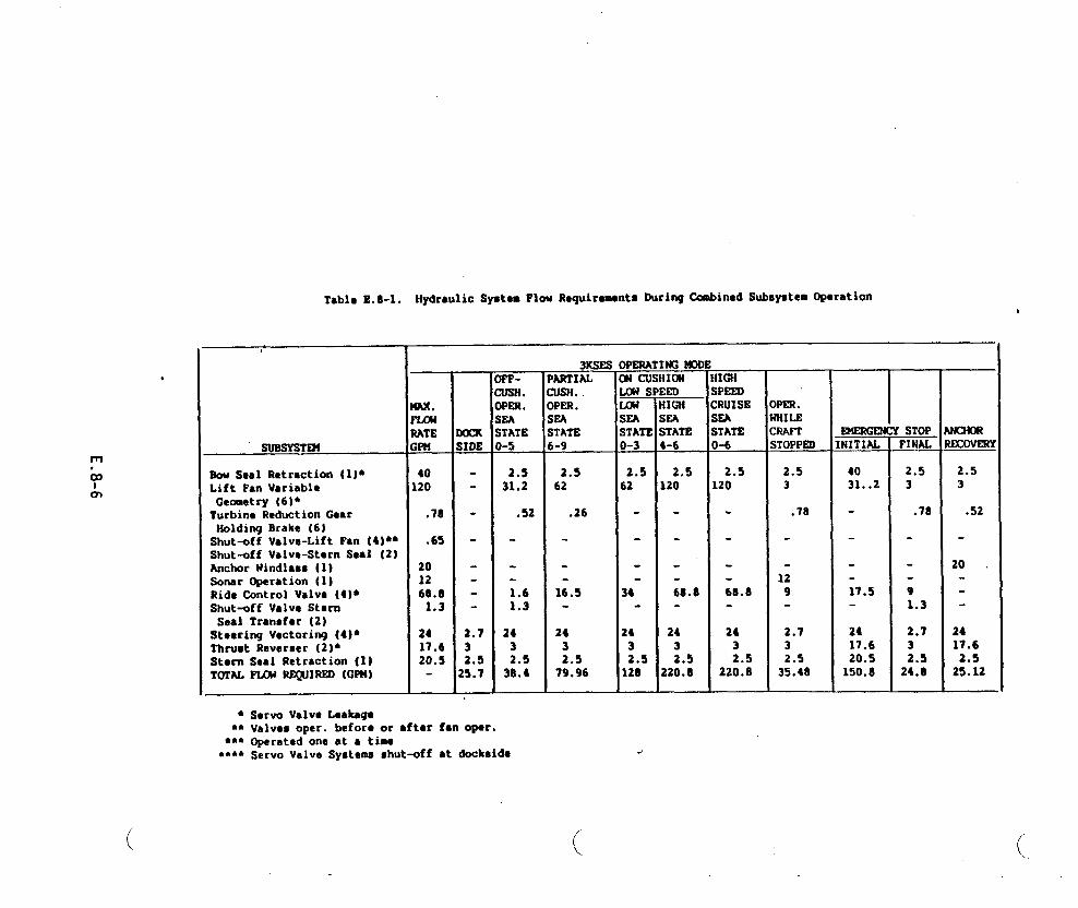
,
HydrmlicSyato. Flow R.quir.ments During Cambined Sutmyatem operation
SUBSYSTR4
fkw Seal Retraction (I)*Lift Fan Variable
Geoaetry (6)*Turbine Reduction Gear
I
Holding Brake (61Shut-off Valve-Lift Fan (4)**Shut-off Valve-Stern Seal(2)Anchor Windlaes (1)Sonar Operation (IJRide (2mtrol Valve (4)*Shutmff Valve Stern
Seal Transfer (2)Ste.ring Vectoring (4J~Thrust Reverser (2)6SternSealRetraction (1)TOTWFTXW lQJIRSD (GPM)
● Servo Valve Leakage
4A%.mRATEWl#
40120
.78
.65
201268.8
1.3
2417.620.5
XxK;lDE
2.732.5!5.7
FF-XJSH.)PER.;SA;TATE)-5
2.531.2
.52
1.61.3
2432.5
38.4
●* Valvee oDer. beforg or ●ftar fanOper.●*soper~ted-oneat a ti~
●*** servo Valve Sygtem Shut-off●t dockside
3KSES OPERATIW~DPARTIAL ICN CUSHICN
--E3JSH. ~:3PSR.SEA SEASTATS STATlb-9 o-3
2.5 2.562 62
.26 -
16.5 34
24 243 32.5 2.5
79.96 120
mIIGNXA;TATSb6
2.5k20
68.8
2432.5
;20.8
41GHSPSSD:RUISESSASTATSD-6
2.5120
68.8
2432.5
220.8
Mm.WLSX/AmSTOPP~
2.53
.78
129
2.732.5
35.48
‘NITIAL-
4031..2
17.5
2417.620.5
150.8
‘ STOPFINAL
2.53
.78
91.3
2.732.5
24.8
WCOVSRV
2.53
.52
20 .
2417.6
2.s25.12
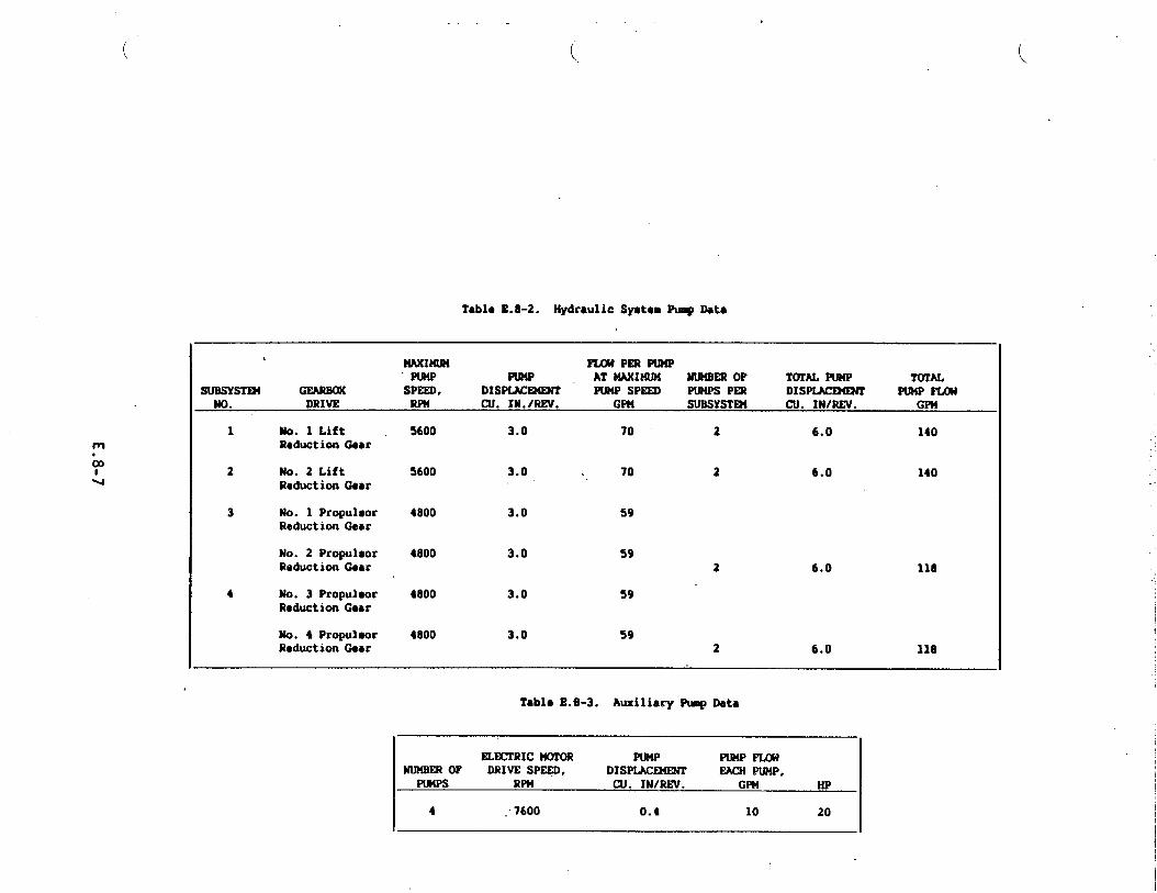
Tablo ft.8-2. Hydrwlic Syctom~Deta
NAXIIURI PLat PsRPtR4P“RR’@ Kw AT WIMJN NIR4BEROF TOTALPunP TOTAL
sussYsTw SPSED, DISP~ PLOW sPEm PuNPs Pm DISP~ PWP P(AWNo. DRIVE m CU. IN./REV. GPN SUBSYSTR4 CU. IN/RSV. GPN
1 No. 1 Lift 5600 3.0 70 2 6.0 140RtductionGear
2 No. 2 Lift 5600 3.0 . 70 2 6.0 140ReductionGear
6.0 118
3 No. 1 Propulsor 4800 3.0 59Reduction Gear
No. 2 Propu180r 4800 3.0 59Reduction Gear 2
4 )/0. 3 Propuleor 4800 3.0 59Reduction Gear
No. 4 Propuleor 4800 3.0 59Reduction Gear 2 6.0 118
Tablo 8.S-3. Auxiliary Pwp Deta
SLSCTRICWTOR PUMP PUNPIWMNU148EROF DRIVS SPSSO, DISPLAC~ SAcN PUNP,
PUNPS RPN CU. IN/REV. GPN HP
4 , 7600 0.4 10 20

b. Modified Central System — This system includes two Pumps Per
lift fan gearbox; othemise, it is the same as the central system.
c. Dual System —The Dual System divides the baseline system into
two separate subsystems, port and starboard. Each subsystem is
powered by three main system pumps. One 4 cu. in./rev. pUIW is
driven by the lift fan gearbox while two 3 cu. in.frev pumps are
mounted on the tw propulsor gearboxes (totaling six pumps for
the Dual System). This system also provides two auxiliary
electric motor-driven pumps of 0.42 cu. in.lrev.capability
for system maintenance Ud for operating the waterjet
closures prior to startup of the engines. The
contains two reservoir-filter - cooler groups,
subsystem.
d. Quad System — The Quad System divides the baseline
system
one in
each
pump
also
each
system into 4
w<
separate hydraulic subsystems. These ‘ separate hydraulicu
subsystems are located in areas adjacent to pump power
suppliers. The Quad System uses eight hydraulic pumps (3 cu.
in.trev. each) - two pumps for ●ach of the four subsystems. The
system also provides four electric motor4riven pumps of 0.42 cu.
in./rev. each; these units are used for system maintenance.
The major weight of hydraulic systems is concentrated in the piping and
associated hydraulic fluid. The Central system has large pressure and
return lines running the iength of the ship. The Dual System contains
slightly smaller pressure and return lines with two sets running the
length of the ship. The Quad System has the smallest pressure and return
lines. These lines are located in”the area adjacent to their pump power
supply. L/
E.8-8
The Central System cannot be effective during a single lift engine
J’ operation nor during a lift engine-driven failure. The modified Central
System does have adequate flow capability during the aforementioned
condition; total pump displacement is 19 cu. in./rev. (CIR).
The Dual System with a total of 3 major pumps and a combined displacement
of 24 CIR provides the desired total flow margin and also provides
functional growth capability for added ship functions.
PUMP S-ION
A variety of hydraulic pumps are available. Some of these can operate
only at low system pressure while others are capable of operating at high
pressure. The selected system pressure is 3000 psi, which narrows the
._/’ field to the use of piston type
fixed or variable displacement.
The fixed displacement pump will
Pumps“ Piston pumps are made in either
always deliver its maximum flow rate are
driven speed. lf the required flow rate at some time is less than the
maximum then the excess flow is bypassed through a relief’valve which
adds
ship
one
heat into the system. The pump delivery requirement for different
operative modes indicates a flow rate range of from 2 to 64 gpm in
of the four Quad Systems. This would mean almost continuous
operation of the relief
Variable displacement
valve.
axial piston pumps maintain a nearly constant
system pressure range by varying the output flow rate to meet system
-d
demand. The displacement or output flow is pressure controlled. If
E.8-9

there is no system demand, the pump yoke will position the piston
assembly for minimum displacement to hold 3000 psi pressure. When a
system demand is made, by usually opening a valve to a subsystem, the
pressure starts to drop. The pmp pressure control senses this pressure
drop and positions displacement (and output flow) to hold the pressure.
The pump will have minimum flow at 3000 psi and maximum flow at
approximately 2900 psi pressure. Thus, the added heat to the system is
minimized by using a
mechanical and volumetric
rated input power.
The pump type selected is
HYDRAULIC FLUID SELECTION
Many hydraulic fluids
variable displacement pump with its normal
efficiency losses only approximately
the variable displacement type.
are available of different
characteristics but all are essentially one of two basic
‘e’
13% of the
‘“w’
formulation and
types; petroleum
base and synetic. The synthetic type fluids can be separated in
chemically compounded and water base hydraulic fluids. Synthtic fluids
are formulated from compounds which are made chemically resistant to
burning by the addition of snuffer agents, usually water, to fhmable
compounds to fom water base fluids. Water alone, or with soluble oil
additives to increase lubricity and reduce mtingr is used in some
industrial applications where large quantities of fluid due to its
restrictive liquid range. high viscosity, low lubricity and corrosive
capability.
u
E.8-10

.
TWO types of hydraulic fluids are presently in use or being planned for -
d future operation of surface effect ship+; hydraulic fluid in accordance
with MIL-H-5605 is employed in the SES 100-Ton Testcraft, and fluid per
MIL-H-83282 will be used in the Amphibious Assault Landing Craft.
Hydrofoil crafts such as PCH-l and Dennison have phosphate ester based
(S~drol) hydraulic fluid in their system.
Hydraulic fluid that meets Specification MIL-H-5606 has been in use for
more than 30 years and is generally accepted as the hydraulic fluid in
industry. It is a petroleum-base fluid, it possesses desirable
characteristics of viscosity behavior with temperature variation and good
lubricity for moving components. The drawback is its low flash point.
\
Phosphate ester hydraulic fluid (Skydrol) was developed primarily for
J“ aircraft systems to improve the fire resistant properties over
MIL-H-5606. However, this fluid is toxic and incompatible with many
materials such as stan&rd seals of Buns N and Vitou materials, painted
surfaces, electric wire insulation etc.
Historically, fire resistant phosphate ester base fluid. in accordance
with MIL-H-194S7, has been used in some Navy ship applications.
this fluid has the problems of toxicity,
aircraft type components qualified for it.
seal compatibility
To overcome these
However,
and few
types of
problems, MIL-H-83282 fluid has
MIL-H-83282 fluid is a new
recently been developed.
synthesized hydrocarbon fluid that was
developed to provide both improved’performance and safety as compared to
wexisting hydraulic fluids. Some of the advantages of this fluid are:
E.8-111

.
a. High operating temperatures and improved themnal characteristics
which allow system operation to at least 400”F. w
b. Improved fire resistance flammability characteristics, resulting
in reduced hydraulic fire hazards related to petroleum-base
hydraulic fluids.
c. It is non-toxic and requires no’ special precautions such as
required by phosphate ester or similar fluids.
PIPING MATERIAL
The hydraulic lines considered here are the high pressure and return
lines consisting of rigid.,
will be used in general,
locally connect the pumps
and flexible material. Lines of rigid material
and lines of flexible material will be used to
and actuators to rigid main distribution lines.
a. (1) Rigid Tubing +3?ES 304-L is the selected material for rigid
tubing: it is readily available in me” rewired t~e
diameters, relatively easy to bend and weld. and is
appreciably less costly than tubing made from 21 Cr-6Ni-9Mn
that requires the procurement of mill runs in sizes greater4
than 1.25 O.D Swaged and weld fittings were selected in
preference to the use of flared fittings in the interest of
minimizing the potential of leakage. Welding is preferred to
brazing because successful brazing requires an inordinate
degree of care and cleanliness, which is costly and difficult
to endure under ship building conditions. In addition,
brazed lines must be flushed with water
the flux. followed by drying of the
E.8-12
zany times to removeu
system with acetone
.
d’
followed by alcohol. Inspection is facilitated, since welded
joints can be ultrasonically inspected, whereas brazed joints
are not readily inspectable.
(2) Flexible Tubing — Wherever flexible tubing is used, it will
be Teflon-lined, since rubber turing takes on a static charge
and picks up and holds dirt despite best efforts to clean the
internal surfaces. Rubber tubing also “sluffs off’*‘~rticles
which can damage servo valves. Fittings that are
particularly designed not to damage the Teflon lining will be
employed with this tubing..
b. Hydraulic Line Jointing — The primary
swage and weld type codiguration to
Where separable lines must be used,
fittings or equivalent is recommended.
fittings will be of the
eliminate line leakage.
the Deutsch or Dynatube
w
Ei8-13

..>’ .
APPENDIX E.9
REFRIGERATION SYSTEM
‘J
.

The refrigeration capacity of each plant is 3/4 ton. Freon 22 has been
.---’chosen as the most practical refrigerant. The following information
gives equipment description and function in detail.
COMPRESSOR
The compressor type is 60 Hz heavy duty reciprocating accessible
hermetic. It is provided with suction and discharge service valves, and
has a force feed lubricating system. The compressor motor is provided
with thermal overload protection as a safety measure.
.
mNDmsER
The condenser is the shell and tube type in whichd
through the tubes within the shell. The condenser is
water circulates
equipped with a
seawater flow valve which is controlled by the refrigerant discharge
pressure.
RECEIVER
The refrigerant receiver has the capacity to hold at least 110 percent of
the no-l operating refrigerant charge. The liquid outlet is covered by
liquid at all times during pitch or roll conditions of the ship. The
receiver has two fused quartz sight glasses equipped with float bills to
determine the refrigerant level. The receiver is designed for a test
._--’
pressure of 450 p8ig.
E.9-1
PRESSURE SWITCX
Pressure switches are provided in the suction and discharge lines from
the compressor. The suction pressure switch is a sin91e pie. single
throw switch with automatic reset on pressure rise. It will uhut down
the compressor when there is a low level of refrigerant or when
refrigerant flow is stopped by the liquid solenoid valves. The discharge
pressure switch is a single pole double throw switch with manual reset.
It will shut down the compressor and actuate an slam circuit in the
event of an overpressure condition.
FILTER-DRYER
The filter/dryer is the replaceable core type. The core material removes
water, acid,
installed with
SIGHT GLAss
A refrigerant
evaporator.
and particulate matter from the refrigerant. It is
isolation valves,f which are used while replacing the core.
flow sight glass is provided in the liquid line to the
The sight glass
indicator. The sight glass with
filterldryer cartridge fitting.
--
EVAPORATOR
incorporates a color code
moisture indicator is combined
moisture
with the
The evaporators are the fan forced circulation
both the Chill and Freeze rooms. The evaporator
E. 9-2
type. There are two in
coil is the copper tube ‘--_-’
., :. .,.,,’... ,.’. .’ -.. “..’,..-,‘,
type and is mechanicall.ybonded to the aluminum fins. Fin spacing is
d
compatible with sub-zero evaporating temperatures. The evaporators and
fans are enclosed in an aluminum housing arranged for overhead mounting.
-ANSION VALVE
Each evaporator is served by a thermostatic expansion valve. The valve
is compatible with both the operating mode and the defrost mode. It is
constructed so that all working parts may be replaced without removing
the valve body
SOLENOID VALVE
from the piping system
Each evaporator/.—
the refrigerated
SUCTION PRESSURE
is controlled by a solenoid valve which is sner~ized by
space thermostat.
REGULATOR
The chiller room eva~rator suction lines are provided with suction,
pressure regulators. They control the evaporating temperature needed to
produce the capacity required in the chiller mode without freezing of the
evaporator. The regulators are internally regulated. A full line-size
manual bypass valve is provided
CRANKCASE PRESSURJ3RHWLATOR
The compressor regulator whiche
condensing unit. The regulator
for operation in the freezer mode.
is provided in the suction line to each
prevents the suction pressure from rising
E.9-3

beyond a pre-detemined limit during a period of pull-do-, when the room.’
temperatures are abnomally high. This control is optional depending on u’
compressor selection.
HEAT EKHANGER
Heat exchangers are used to fully vaporize the suction gas. or to further
sub-cool the liquid refrigerant. This component is optional depending on
compressor selection.
MANUAL VALVES
Manual valves are of the diaphragm globe type in full line size.
CONTROL REQUIREXEN’TS
The refrigeration system requires tith remote and local controls systems.
~OTE CONTROLS DESCRIPTION .*
The refrigeration system remote controls command the operation of the
evaporators and fans for system Number 1 and system Number 2.
Refrigeration system Number 1 controls one evaporator and one fan in the
Freeze Room, and one evaporator and one fan in the Chill Room. Similar
controls apply to refrigeration system Number 2. The off comand is the
only remote control rewired for ~ (in the Central Control Station)
from the refrigeration system. ‘“
“2’
w
E. 9-4

,.
The refrigeration system is normally in continuous operation and would be
.1
shut down only during the defrost mode or an emergency condition.
Reference G.Ei Ship Control Ilrawing”SK56137-61-20 for the refrigeration
system IXAEC Control Panel layout.
The refrigeration system command controls and monitor controls will
interface with Data Teminal Number 3, which will receive and tr==mit/
these signals to and from the _ panel in the central control station.
-(3TE CONTROL FUNCTIONS
Remote control functions are as follows:
a. Comands
1. Refrigeration System No. 1 - off control only
2. Refrigeration System No. 2 - off control only
b. Monitors
1.
2.
3.
4.
5.
6.
Freeze Room high temperature alarm
Chill Room high temperature alarm
Refrigeration
Refrigeration
Refrigeration
Refrigeration
System No. 1 status
System No. 2 status
System No. 1 fault alarm
System No. 2 fault alarm
*
w
E.9-5

La CONTROL DESCRIPTION
w;
The local control panel -is located in the Refrigeration Machinery Room.
The local operator will be able to perform all operations and controls of
system Number 1 and, including startt stop, and defrost functions. THe
front panel contains switches and indicators labeled according to their
function. The rear of the panel contains relays, contactorst and
terminal boards.
_ CONTROL FUNCTIONS
The main function of the local control panel is to start up refrigeration
system Number ql and Number 2, and maintain continuous operation until
defrosting or nmintenance is required. The local control operator amy
then shut down the system by either depressing the on/off switch to the b’
off position, or depressing the defrost switch. The later action turns
on the defrost heater(s) that begin the defrost sequence. After defrost
or maintenance is completed, the onloff switch is depressed to the on
position, and normal operation is resume.
There are two maintenance switches, one for System No. ~. one for system
No. 2. These switches are used to trouble-shmt the freeze and chill
systems by opening the thermostat paths and also the paths to the
refrigerant valves, isolating problem areas.
The chill room has the capacity to be used as either a chill or freeze
space. Therefore, a chill~rtfreezer select switch has been proved on the
local control panel to select the desired mode for the space. Theu
E.9-6

Iocaltremotm select switch is used to put ‘the system either in local or-/
remote control mode. If in the local” mode of operation. the system
cannot be turned off by the remote operator. If in the remote mode of
operation, only the remote
Refrigeration System Controls
The 3KSES Auxiliary Systems
with the ship specification
operator will shut down the system. See
Diagram, Figure E.9-1.
Specification was developed in accordance
and implicates Section 516 of the GSS and
MIL-R-16743.
The intent of
Refrigeration
reduce weight
d the following
Section 516 has been followed in the development of the
system. but not strictly adhered to. In an effort to
and complexity without sacrificing performance or safety,
requirements per Section 516 have not been incorporated in
the Refrigeration system.
a.
b;
c.
d.
Interchanger on the liquid line with shut off valve. (Having two
refrigerant plants eliminates the need for this valve).
Replacement charge of R-22 and lubricating oil-, one per plant,
(Two independent plants eliminates the need for redundant service
materials).
NAVSHXPS Drawing No.
penetrations. (This
810-1385899 to be used for refrigeration box
stan&rd penetration was determined to be
too complicated and-unnecessary).
Hot gas by-pass between compressor discharge
valve. Hot gas control valve, and additional
and expansion
solenoid valve.
(Function replaced by evaporator pressure regulator and electric
defrost).
E.9-7 ,
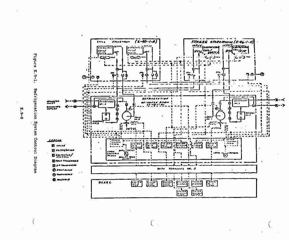
ti
.
‘L-Z-Z ----’--+ --r--l r-=1-.-”r: ‘[- ~ ....M
,** ~ _.I-i $ ~------ ---- J- J.--- Y--- –--”--- -J-: Ct
(

.,..,. :.. . .. . . “.: ‘.’.—
,,,
e.
J
f.
9=
h.
J
i.
Portable vacuum pump, hoses, and a&ptor for evacuating and
dehydrating refrigeration system to be stored o-rd.
(Impractical from a weight standpoint. See Item b.).
Provide separate refrigeration circuits for
space, with valves to cut off service.. (In
separate circuits for each space because
each refrigerated
effect, there are
of two separate
systems. Because the refrigeration system is not a standard
system, the valves are not needed).
Distribute air by means of duct work. (Compartment size is such
ducting is not required).
Coil defrost to be accomplished by means of hot seawater spray.
(From a weight standpoint (additional piping system) and system
simplification, electric defrost was determined to be a more
practical defrosting method).
All safety control as invoked by
The 3KSES Auxiliary System was reviewed
MXL-R-16743.
by the Navy. They requested the
following be added to the specification: “The refrigerating units shall
be provided with operating and safety controls as required by
MIL-R-16743“. Because the refrigeration system is not the type usually -
installed in Naval vessels, this could not be added without redesigning
the system, adding the weight and complexity of a typical system. The .
Navy then agreed that we would.instead follow the”intent of MIL-R-16743,
without sacrificing safety or perfo-nce. This has been accomplished,
and listed below are the operating or safety controls not relevant to the
current design configuration.
.J
a. Oil failure switch
E.9-9
. .
b.
c*
d.
e.
f.
9*
h.
i.
j“
Oil indicator
Water failure switch
Shut-off valve (between condenser and receiver)
Pressure relief valve (bypasses shut-off between condenser and
receiver).
Hand expansion valve (bypass there expansion valve).
Shut-off valves (at evaporator outlet for each cooling coil).
Liquid line strainer (in addition to dehydrator/filter).
Suction line strainer (between suction shut-off and compressor).
Moisture indicator (in addition to sight flow indicator).
w
Heat load circulation for the refrigeration system have been performed in
accordance with DDS 516-1, and equipment is sized and selected
accordingly. There have been some tradeoffs with regard to equipment. d
Initially, a centrifugal type compressor was considered, but commercial
availability was poor, and it was not particularly suited to the system.
A 60 Hz hermetic compressor is the current selection; it is heavier. but
less expensive, readily available, and suits the refrigeration
application. The major tradeoff in the refrigeration system is”the use
of the split system. which was chosen over the standard system primarily
for reliability. Each system serves the chill and freeze room. In the
event of a system failure, the other system will be employed, insuring
maintained compartment temperatures.
E.9-10

APPENDIX F
WEIGHT ESTIMATE
.
.--’
0
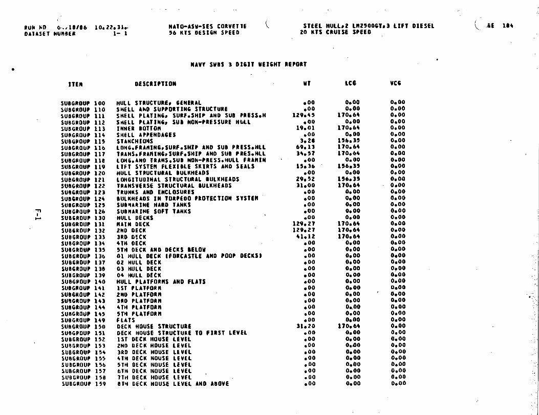
.
Lzm
Ooeooooooooeo
000000000000000000000000
00000000
00000000000000000000000000
0000000000000000000
●●
●●
●●
●●
●●
●●
●●
●●
●●
●●
●●
●9*O
0.00●
●●
●●
,●
●●
●●
0●
●●
●0000000000000000000000000
00000000000000000000
dm
oo*o
*om
**om
o-+
*00000***0
0O
ooooooooooe
000000000
eo4f3
40-4
.9=m
em
eoooooaeeoo000000000009
ooQ
oooeo’o
●●
●*
●●
●●
●●
●●
●*
●●
“0●
●**
●***
●●
●●
●●
●d
O**
●●
●●
*8
0●
●oogo:o
g:g
ego
$goeooog~goo
00000000000:
oooooeooo
dd
&d
*-
-dd
d-
d
0000-$
0---0
40
6JO
OO
OO
O**N
O0
000000000000000000000
00#0O
OW
Am
Om
O-O
OO
OO
OfU
tUdO
O0000O
OO
OO
OO
N000000000
G*;
●$
●**$
**●
mo●
**:●
●*
●●
●●
●0
9●
●●
●***
●●
●●
●●
●●
●●
●*
●●
tud
g-
dm
mH
w>0:
0xa
ra0lbk-
4zU
Io
Xr
)-+*Q
axa+a.#
a0m
F-1

kUN NO 04110186 10.22*31b NATO-ASU-SES CORVETTE STEEL HULLF2 LH25006Ts3 LIFT DIESELOATASFT NURBER 1- 1 56 KTS DESIGN SPEED 20 KTS CRUISE SPEED
PAGE 105
NAVY SUBS 3 0161T UEICHT REPCIRT
ITEN
SUBCROUP 140● SUBGROUP lbl
SUllGROUP 162SUBGROUP 163SUBGROUP 164SUBGROUP 165$llBGRouP ~~4SUBGPOUP 167SU8GROU? 160SU86@OU? 169SUBGROUP 1?0SURGROUP 171SUBGROUP 172SUBGROUP 179SUS6ROUP lEO
w SU86ROUP lClL SUBGROUP 102
SU9GROUP 103SU86POUP 10+sue69au~165SUB6ROUP 106SUt)GROUP 187SUBGROUP 190SUBGROUP 191SU86ROUP 197SUBGROUP 190SU8GROW 199
TOTAL 6RP 1
DESCRIPTION
SPECIAL STMJCTUB[SSTRUCT* CASTOCFORG1N6S0 ANO EQUIVOME1OHTSTACKS ANO ltACKS (COHDIMED STACKp MAST.]SEA CHESTSBALLISTIC PLATINGSOMAR MIRESSPONSONSHULL STRUCTURAL CLOSURESDECKMOUSE STRUCTLIRAI. CLOSURESsPECIAL PURPOSE CLOSURES AND STRUCTURESflASTSS K1N6POSTSS AND SERVICE PLATFORMSMASTSS TOMERSS TETRAPODSKIN6POSTS ANO SUPPORT FRANESSEQVICE PLATFORMSFOUNOATXOHSHULL STRUCTURE FOUNDATIONSPROPULSION PLANT FOUNOATIOMSELECTRIC PLANT FOUNDATIONSCORHAND AND SURVEILLANCE FOUNDATIONSAUXILIARY SYSTENS FOUNDATIONSOUTFIT ANO FURNISHINGS FOUNDATIONSARMAMENT FOUNDATIONSSPECIAL PURPOSE SVSTENSBALLASTsFIXED OR FIUIDSANO BUOYANCY UNITMELDINGFREE FLOODING L1OUIOSHULL REPA!R PARTS AND SPECIAL 1001S
MULL STRUCTURE
(.
MT
.006a18
● 00●B8● 00●OOboo4.?1
●OO6s108,36
boo●OO●OO●OO.00
11*913*212*6S5*641.41
●9113,9B
●OOb00●OO●OO
728*24
LCG
Oboo170e6+O*OO
170,64Oe00ObooO*00
170064o*00
170s6$156,35Oe00O*OO0.00O*QOOboo
156s35156,3515603!I156s3$156c35156,35170.6?0.00O*OOO*OOo*00
lbVe02
VC6
O*OOo* 00O*OO0,00O*OO0.00O*OO0.00O*OO0.000900O*OOO*OOOaooO* 00Oboo00000,000.00O*OOO*OO0.000.000.00O*OO0.000000
0,00
(,

( (“RuN NO 04/10fl)6 10s22031oOATASET NUMBER 1- 1
ITEN
SUBCROUP 200SUBGROUP 210SUB6ROUP 211SUOGROUP 212sUBGROUP 213SU8GROUP 214SUBGROUP 215SUBGROUP 216SUBGROUP 217SUB6ROUP 2L@SUBGROUP 219suBGeouP 220SUB6ROUP 221SUBGROUP 222SUBGROUP 223SUBGROUP 224SUBGROUP 230SUBGROUP 231
~ SUOGROUP 232U SUB6ROUP 233
SUB6ROUP 234SUBGROUP 235SUBGPOUP 236SUBGaOUP 237SUBGROUP 230SUB6ROUP 239SUBGROUP 240SUBGPOUP 241SUBGROUP 242SUBGROUP 243SUB6ROUP 244SUBGROUP 245SUBGROUP 246SU86ROUP 247SUBGROUP 248SUBGROUP 250
,. SUBGROUP 251SUBGROUP 252SUBGROUP 253SUBGROUP 254SUBGROUP 255SU9GROUP 256SUBGROUP 258SUBGROUP 259SUBGRJUP 260
NATO-ASU-SES CORVETTE\
STEEL HULLS2 Ln2~oOGT~3 LIFT DIESEL56 KTS 0ES16N SPEEO 20 KTS CRUISE SPEED
DESCRIPTION
NAVY SUSS 3 01611 UEIGHT REPORT
PROWLSION PLANls CEMtRALENER6Y 6ENEBATIN6 SYSTEM tMUCLEAR)lRESERVEO)NUCLEAR STEAM GENERATORREACTORSREACTOR COOLANT SYSTEH.REACTOR COOLANT SERVICE SYSTERREACTOR PLANT AUXILIARY SYSTEMSNUCLEAR POUER CONTROL ANO SNSTRNENTATIONRAOIATION SWELOIN6 lPRINARY)RAOIATION SHIELDING (SECONOARYIENERGY GENEBATIN6 SYSTEM (NON-NUCLEARJ?ROPULSION 801LERSGAS GENERATORSRAIN PROPULSION IIATTEREESMAIN PROPULSION FUEL CELLSPROPULSION UNITSPROPULSION STEAK TURBINESPROPULSION STEAM ENGINESPROPULSION INTERNAL COMBUSTION EN61NESPROPULSION 6AS TURSINESELECTRIC PROPULS1ONSELF-CONTAINED PROPULSION SYSTEMSAUXILIARY PROPULSION OEVICESSECONOARY PROPULSION ISUBNARINES)ERER6ENCY PROPULSION fSUBHARINES)TRANSIIISSION ANO PROPULSOR SYSTEllSPROPULSION REOUCTION 6EARSPROPULSION CLUTCHES ANO COUPL1N6SPROPUL$1ON SHAfT1N6PROPULSION SHAFT SEARIN6SPROPULSORYPROPULSOR SIIROUOS ANO OUCTSMATER JET P80PULSORSLIFT SYSTEM FANS ANO OUCTINGPROP. SUPPORT SYSOtEXCEPT FUELCLUBE OILlconwsrIoN AIR SYSTEHPROPULSION CONTROL SYSTEMHAIN ST[AH PIPIN6 SYSTEMCONOENSORS ANO AIR EJFCTORSFEEO ANO CONDENSATE SYSTEMCIRCULATIM6 ANO COOLIM6 SEA MATER SYSOH-P, STEAM ORAXN SYSTEMUPTAKES (INNER CASING)PROPO SUPPORT SYSO (FUEL AMO LUtE OIL)
●OO●OO●OO●00●OO●OO●OO●00●OO●OO●OO●00●00● 00●oo●00● 00●00●OO
20.4017060
●00●00● 00●00●00●00
60.002*I530000
006026000
● 00●00
13000●00
00008.16
●00● 00,00
3020●005000eoo
LC6
00000.000.00O*OO0.000.000000O*OO0.00O*00O*OO00000000O*OOO*0000000s000.000000
156.35156,35
00000,00
53,4900000.000.00
156.35156035156035156035156-35
0000O*OO
156,350.4)0
156035156035
O* 000.00o* 00
1560350.00
156,350.00
, VCG
0000O*OO0.0000000.000.000.0000000.0000000.0000000.000000O*OO0s000000O*OOO*OO0.000.0000000.000000O*OOO*OO0000O*OO0.000.000.000000O*OOO*OO0.000.0000000.00O*OO0.000.000.000.000.000.00
.

RuN NO 04/ld166 IOO22O31OOATASFT NUMBER
MATO-ASU-SES CORVETTE STEEL HULLS2 km25006Ts3 LIFT OIESEL1- 1 56 KTS 0ES16N SPEED 20 KTS CRUISE SPEEO
ITEM DESCRIPTION
NAVV SUBS 3 DIGIT wEIGHT REPORT
SUSCROUP 261 FU6L SEWICE SYSTEMSU06ROUP 262 MAIN PROPULSION LUBE OIL SYSTEMSUSGROUF 263 SWAFT LU6E OIL SYSTEIl ISUBHARINES)SUBGROUP 26+ LUBE OIL FILLp TRANS. ANO PURIFICATIONSUBGROUP 250 SPECIAL PURPOSE SYSTEMSSUOGROUP 290 PROPULSION PLANT OPERATING FLUIDSSUBGROUP 299 PROPO PLANT REPAIR PARTSO SPECIAL TOOLS
TOTAL 6RP 2 ?ROPULSIOM ?l.ANT
MT
6*690020boo
Y*76b002.005*30
230s14
LcG Vcc
15b035 O*OO156*35 O*OO0.00 O*OO
156035 O*OO0.00 0.00
156.35 0.00156.35 ‘ 0.00
156s35 O*OO
(.. ,.
(..

/@uN NO O+; 18b 10022*31o NATO-ASM-SES CORVETTEDAIASFT NuMBER 1- 1 56 KTS DESIGN SPEEO
ITEM
SU86tOUP 300SUBGROUP 310SUB6ROUP 311SUB6ROUP 312SUBGROUP 313SU86ROUP 314SUBGROUP 320SUBGROUP 321SUOGROUP 322SU8GROUP 323SU86ROUP 324SUBGPOUP 330SUBGROUP 331SUBGROUP 332SUOGROUP 340SUBGROUP 341SUB6@OUP 342
~ SUBGROUP 343ul su06RouP 390
SUB6ROUP 390SUBGROUP 399
TOTAL 6RP 3
MAW SUBS 3 DIGIT ME16HT REPORT
STEEL 14ULL02 LN2500GTs3 LIFT DIESEL20 KTS CRUISE SPEED
DESCRIPTION . u?
ELECTRIC PLANTs GENERALELECTRIC POMER GENERATIONSMIP SERVICE POMfR GENERATIONERER6ENCV 6WERATORSDATTERIES ANO SERVICE FACILITIESPOMER CONVERSION EQUIPNENTPOdER DISTRIBUTION SYSTEHSSHIP SERVICE POMER CABLEEHER6ENCY POMER CAOLE SYSTEllCASUALTY POMER CABLE SYSTEMSMITCH6EAR ANO PANELSLIGHTIN6 SYSTEMLIGHTIN6 DISTRIBUTI(MIL16HTIN6 FIXTURESPOUER GENERATION SUPPORT SYSTEMSSST6 LUBE OILDIESEL SUPPORT SVSTENSTURBINE SUPPORT SYSTEMSSPECIAL PURPOSE SYSTEPSELECTRIC PLANT OPERATING FLUIDSELECOPLANT iREPA18 PARTSS SPECIAL
●00●00
11025.00.58
3.bO●oo9012
● 00.325*25,002*422.92
●00● 00●OO9.15
●OO3.00
TOOLS 1050
ELECTRIC PLANT 49*O9
LCG
0.000.00
156.350.00
15b03515b.350.00
156,350.00
156035156*350.00
15b,3515b,350.000.000.00
156.35Oe00
156.3515b.35
156,35
UC6
0.00OeOOO*000,000.00O*OO0,00.O*00O*OO0.00O*OO00000.0000000.00O*OO0.00ObooO*OOO*OOO*OO
0000
.,
K 180
.
I

hUN NO 0$l18f8b 10022*31mOATASET hUM9ER 1- 1
ITEN
SUBGROUP 400SUB6ROW 410SUBGROUP 411SUBGROUP 412SUBGROUP 413SUB6ROUP 414SUB6ROUP 415SUBGROUP +17SUBGROUP 420SUBCROUP 421SU86ROUP 422SUBGROUP 423SUB6BOUP 424SUBGROUP 425SUB6RDUP 426SUBGROUP 427SUD6POUP 420SUBGROUP 430
~ SUB6ROUP 431m SUB6ROUP 432
SUBGROUP 433SUB6@OUP 434SUBGROUP 435su06Rou@ 436SU06ROUP 437SUEJ6ROUP430SUB6ROIJP 439SUBGOOLI? 440SU66ROW 441SUDGOOUP 4425UBCIPOUP 443SUBGROUP 444SUBGROUP 445SUBGROUP 44bsu~6Pou@ 450SUBGROUP 451SUOG@OUP452SU8GROUP 453sitB6PouP $54su~GRoup 455SU9GROUP 456SUBGROUP 459SUBGROUP 460SU5GPOU~ 461SUBGROUP 462
MATO-ASM-SES CORVETTE STEEL HULL*2 Ll125006Ts3 LIFT DIESEL56 KTS OESICN SPEED 20 KTS CRUISE SPEED
OESCUIPTIOM
NAVY SUBS 3 0161T UEIGMT REPORT
COMRAND ANO SURVEILLANCES 6tNERALCOHliANO ANO CONTROL SYSTEHSDATA OISPIAV 6ROUPDATA PROCESSIN6 GROUPDIGITAL DATA SMITCMOOAROSSINTERFACE EQUIPMENTDIGITAL OATA COMHUNtCATIONSCORN4N0 ANO CONTROL ANALOG SMITCHDOARDSNAVIGATION SYSTEMSNON-LLECTRICtELECTRONIC NAVI6ATION AIO$Electrical MAVICO AIDS(INCLONAVIGOLIGHTJELECTRONIC NAVIGATION SYSTEHSS RADIOELECTRONIC NAVXGATION SYSO ACOUSTICALPERISCOPESELECTRICAL MAV16ATION SYSTEMSINERTIAL NAVIGATION SVSTEHSNAVIGATION CONTROL RONITORIWINTERIOR COMHUNfCATIONSSMITCHBOARDS FOR I,C.ISYSTEllSTELFPIiONE SYSTEMANNOUNCING SYSTERSENTERTAXNNENT ANO TRAINING SYSTEMSVOICE TUBES AND PESSA6E PASSING SYSTEMSALARltc SAFEIYc ANO MARNIN6 SYSTEMS2NOICATING~ OROER#AND METERING SYSTEMSINTEGRATED CONTROL SYSTENSRECOROIN6 AtiO TELEVISION SVSTEMSEXTERIOU CORRUMICATIOMSRADIO SYSTgJISLINDERMATER SYSTEMSVISUAL AND AUDIOLE SYSTEHSTELEMETRY SVSTERSTTY ANO FACSIMILE SYSTEMSSECURITY EQUIPMENT WSTEMSURVEILLANCE SYSTEMS (SURFACE)SURFACE SEARCH RADARAIR SEAtICH RADAR [20}AIR SEARCH RAOAR (30)AIRCRAFT CONTROL APPROACH RAOARIOEMTXFICATION SYSTEMS {IFF)MULTIPLE ROOE RADARsPACE vEHIcLE ELECTRONIC TRACKINGSURVEILLANCE SYSTEHS (UNDERMATER)ACTIVE SONARPASSIVE SONAR
MT
● 00●0010052.00
.00● 00● 00●OO●OO●1O●1O●bl●27,00●3O●16●oo.00●15●o3●15●51boll● 00●OO,29.03●OO3.93●55●72●OO●10,19.00●lb.00g00●OO●e71.00
●OO.00.00.00
LCG
0.00O*OO
15be3515b.3S00000.00o*00O*OO0.00
15b.35136.351566351569350.00
15bs35196035o*000,00
15b~3515b.3515b,35196.35156s350.000.00
15b035156.350.00
15bc 35156.3515b0350.00
156.35156,350.00
15bs350.00O*OOO*00
15b.35156.35O*OO00000.000.00
VC6
0.00O*OO06000.000.000.00O*OO0.000.000.000.00O*OO0.000.00”0.000.00O*OOO*OOO*OOO*OO0.000.00O*OOO*OOO*00O*OO09000.000.DO0.000.00O*OO0.000,000,000.000.00O*OO0.00O*OO0.000.0000000.00O*OO
PA6E le9
(L..

RUN NO 04,, 86 10*22.3I.DATASET NUM8ER 1- 1
●
sUBGROUP 463SUBGROUP +6+SUBGROUP 465SUBGROUP 470sue6110uP 471SUBGPOUP 472SUBGROUP 473SUBGROUP 474SUB6ROUP 475SU06ROUP 4?6SUBGROUP 480SUBGROUP 401SU9GR!IUP 462SUBGROUP 483SUBGROUP 404SU8GROUP 469SUBGROUP 490
~ SUB6ROUP 491-J SUB6ROUP 492
SUBGPOUP 493SUB6ROUP 494SUBGROU@495SUBWOUP 490SU8GQOUP 499
TOTAL 6RP 4
NATO-ASM-SES CORVETTE ( STEEL HUI.LS2 LH2500GTs3 LIFT OIESEL56 KTS OES16M SPEEO 20 KTS CRUISE SPEEQ
MAW SMtS 3 01611 ME1W3 REPO@T
OESCRIPTIOM MT
MULTIPLE MO~E SONARCLASSIFICAT!iON SOMARBATHVTHERROCRAPHCOUNTERMEASURESACTIVE ECH (INCL COHBOa AC81VE/PASSIVE~PASSIVE ECIITORPEOO OECOYSOECOYS (OTHERI0E6AUSSIN6HINE COUNTERMEASURESFIRE CONTROL SYSTEMS6U~ FIRE CONTROL SYSTEMSRISSILE FIRE CONTROL SWTEIISUNOEUMATER fIRE CONTROL SYSTEMSINTEGRATE FIRE CONTROL SYSTEHSMEAPON SYSTEM SMITCHOOAROSSPECIAL PURPOSE SYSTEPSELECO TEST* CKOUTP AMO HONX?ORING EQUIP.FLIGHT CONTROL ANO INSTRMT LANOIN6 SYSONON COllBAT OATA PROCESSING SVSTENSHElkOROt061CAL $YSTENSSPECIAL PURPOSE INTELL8GEHCE SYSTEHSCOfiHAND ANO SURVEILLANCE OPERATINC FLUIOCORHANOS SURVO REPAIR PARTS8 SPECO TOOLS
COttNANO AND $URVEI1O
7.962.65
●OO,004.30
●OO●OO3.7029.69.00.00●OO.003.281.40
●OO●00●00●00● 00●OO.00boo●10
66078
LCG VCG
156.35156,35O*00o*00
1560350.000.00
156.35896.350.4)0O*000,00 .O*OO
156.35156.350.000.0000000.00O*000.000.00Oboo
156e35
156.35
0.000.000.00O* 00O*OO0.00O*OO0.000.00O*OO0.00O*OO0.000.0000000.000,000.000.000.000.000.00O*OOOboo
O*OO
..

RUN NO 0+118166 10.22031?OATASET NUM(IER 1- 1
ITEM
SU8GRtNJP 500SUBGROUP 510SUBGUOUP 511SUBGROUP 512SUBGROUP 513SUBGROUP 514SUBG@OUP 515SUBGROUP 516SUOG?OUP 5175bB6RouP 520SUBGROUP 521SUBGROUP 522SUBGROUP 523SU@GROUP 524SUBGROUP 526SUBGROUP 527SUBGROUP 528
~ SUBG@OUP 929
03 SUf16POUP 530‘SUBGROUP 531
SUR6UOUP 932SUBGROUP 533SUBGROUP 934SUBGROUP 935SUBGROUP 536SU86ROUP 5+0sueGeouP 541SUBGROUP 5+2SIJOGIfOUP 943SUl!6ROUP 544SUBGROUP 545SU86ROUP 549SU6GROU? 950SUBGROUP 551sua6RouP 552su@6RouP 553SUB6ROUP 554SU86ROUP 5s5SU6G@OUP 556SUEIGROUP 557SUBGROUP 5S8SU6GROUP 560SURGROUP 561SUBGROUP 562SUBGPOUP 563
NATO-ASM-SES CORVETTE STEEL HULLS2 LR2SO06TS3 LIFT OIESEL56 KTS 0ES16N SPEED 20 KTS CRUISE SPEEO
PAGE 191
DESCRIPTION
AUXILIARV SYSTEMSCLIMATE CONTROL
MAW SUBS 3 OICIT UEIMT PE?ORT
GENERA1
COHPARTflENT HEATING SYSTEMVEMTII.ATION SYSTEMRACHIMERY SPACE VENTILATION SYSTEMAIR CONDITION1N6 SYSTEMAIR REVITALIZATION SYSTERStSUOHARINEStREFRIGERATION SYSTEMAUXILIARY BOILERS AND OTHER HEAT SOURCESSEA MATE@ SYSTEMSFIREMAN ANO FLUSMIN6 (SEA MATER) SYSTEMSPRINKLER SYSTEMUASMDOMN SYSTEtlAUXILIARY SEA MATER SYSTEflSCUPPERS AMO OECK ORAINSFIREHAN ACTUATEO SERVICES - OTHERPLUMBING 0RAINA6[DRAINAGE AND BALLASIIN6 SYSTEMFRESH WATER SYSTENSDISTILLING ?l.ANTCOOLING MATERPOTABLE MATERAUXOSTEAK ANO ORiINS MXTHIN MAC141NE* BOXAUX.STEAH ANO DRAINS OUT OF RACtlINEO BOXAUXILIARY FRESH MATER COOLIM6FUELSC LU6RICANTSS HANOLIM6 ANO STORA6ESHIP FUEL AND FUEL COMPENSATING SYSTEMAVIATION AND GENERAL PURPOSE FUELSAVIATIONp GENERAL PU@POSE LUSE. OILLIQuIO CARGOTANK HEATIM6SPEC. fUELs LUBE. HANDLIN6p STOUA6EA?R~ GAS~ ANO MISC. Fll)IO SYSTEHSCOMPRESSED AIR SYSTEMSCOtlPRESSEO 6ASES02 N2 SYSTEM1P BLOWFIRE EBTtN6UtSMING SYSTEMSHYDRAULIC fLU!O SYSTEIILtOUIO GASESO CAR60SPECIAL PIPING SYSTEMSSHIP CONTROL SYSTEHSSTEER!N6 AND DIVING CONTROL STSTEIMRUODERHOVERING ANO DEPTH CONTROL [SUBMARINES)
MT
● 00●oo●65
3,272.61
15009● 00●9O●oo● 00
2.29●13boo.65●25●00
4.581.47
● 00%8820613030
●OO● 00●00●OO
13.052*1+
●+4●00● 00b00● 00
7.98●OO●oo● 00
0.839017
●OO●OO●00
2.452.58
●OO
LCG
Oeoo0,00
1S6.35156.35156,35156*350,00
1560350.000.00
156s35196.350.00
156*35156.35O*OO
156s35156.35O*OO
156*35156,35156G3Y0.00o*000.000,00
156.35156.35156.35o*000000o*00o*00
136,350000o* 000.00
156.35156.35
0.000.000000
156.35156.35
0.00
Vce
0.000.000.00O*OOo*000.000.000.000.000.00O*OO00000.000.000.00O* 000.000.00O*OO09000.000.000.000.000,000.000.000.000.000.000.000.000.00O*OO0.000.000.000.000.00O*OO0.00O*OO0,00O*OO0.00
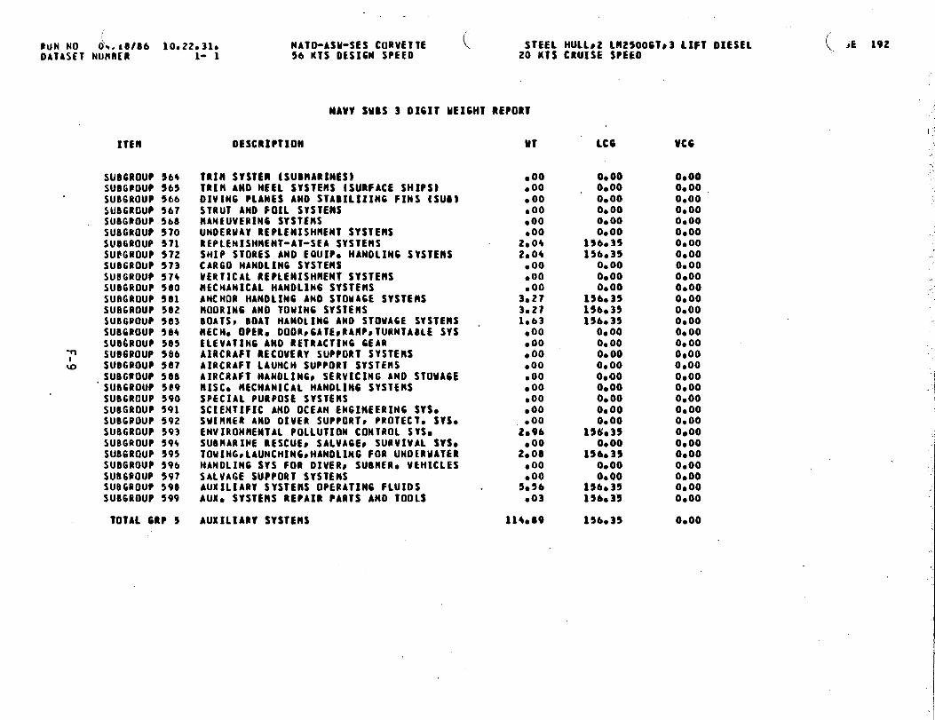
/PuN NO d~. 18/66 10a220310 NATO-ASM-SES CORVETTE [DATASET NURRER 1- 1 56 KTS DESIGN SPEED
STEEL Hu1L02 M2500GTP3 LIFT OIESEL20 KT$ CRUISE SPEEO
SuSuSu
;:SuSuSUSuSuSuSuSu
;:Su
~
m ::, Su
SuSuSuSuSuSuSUSU
;:Su
ITEM
16ROUP 56+IGOOUP 56516ROUP 566)6ROUP 567lGROUP 568IGROW 57016ROUP 571IGROUP 572)6ROUP 573IGROIJP 57+16ROUP 580IGRoUP 58116ROUP 582lGPOUP 583IGROUP 58416ROUP 58516BOUP 586IGBOUP 587)GaOUP 588)6ROUP 5@9L6ROUP 590lGROUP 591lG@OUP 592IGROU? 59316ROUP 59416ROUP 595IGROUP 59616ROUP 597ICROUP 59016ROUP 599
TOTAL 6RP 5
NAVY SUBS 3 01611 MEICH% REPORT
TRIllSYSTEM {SUBMARINES)TRIM ANO MEEL SYSTEM {SURFACE SHIPS)DIVING PLAMES ANO STABILIZING FINS (SLID}STRUT ANO FOIL SVSTEMSNAMfUVERIN6 SYSTEMSUNOERMAY REPLENISHMENT SYSTEMSREPLENISMNENT-AT-SEA SYSTEMSSHIP STORES AND EQUIPC HANOLXN6 SYSTEMSCARGO HANOLIN6 SVSTEfiSUERTICAL REPLENXSHHENT SYSTERSMECHANICAL HANDLIN6 SYSTEMSANCHOR HANOLIN6 ANO STONA6E SYSTEMSl100RIN6 ANO TOWING SYSTEllS80ATS~ 80AT tlANOLIM6 ANO STOMA6E SYSTEMSRECH, OPERa 000RJfiATEsRAHPsTURNTA8LE SYSELEVAT1N6 ANO RETRACTIN6 GEARAIRCRAFT RECOVERY SUPPORT SYSTEMSAIRCRAFT LAUNCH SUPPORT SYSTEHSAIRCRAFT MANOL1N69 SEllVICIN6 ANO STOMA6EIIISC. MECHANICAL HAND11N6 SYSTEMSSPECIAL PURPOSE SYSTEHSSCIENTIFIC AND OCEAN EN61NEERIN6 SYSOSUItlMER AND OIVER SUPPORT~ PROTECT. SYSOENVIRONMENTAL POLLUTION CONTROL SYSOSUbNARIPE RESCUES SALVA6E~ SURVIVAL SYSOTOUING,LAUNCHIN6SMANDLIN6 FOR UNOERMATERHANOLIN6 SYS FOR OIVER~ SUBNER. VEHICLESSALVAGE SUPPORT SYSTEMSAUXILIARY SYSTEM 0PEBATIN6 FLUIOSAIM. SYSTEHS REPAIR PARTS ANO TOOLS
AUXILXARV SYSTEMS
MT
g00●OO● 00●OOSooboo
2*O42*O4
●OO●OO● 00
3*273.27l,b3
coo●OO● 00●OO.00.00●OOg00●OO2,96boo
2.00●00●OO5e56
●03
114089
LC6
O*00Oeoo0.00Oe00O*OO0.00
156.35156a350,00O*OOo*00
156s3515b~35156035O*000,000.000.000,000.00Oe0000000.00
196b35Oe00
156.35o*000.00
15b.3515b.35
156035
VC6
O*OOO*OOO*OO0.00O*OO0.000.00O*OO0.00O*OOOeoo0.00O*OOO*OOO*OO0.0000000.00O*OO0,000.000.000.00O*OOOboo0.000.00O*OO0.00Oboo
0000
(, ;E 192
.
I

RuN N(3 0+/10106 10s22031oDATASET NURSER 1- 1
ITEM
SU06ROUP 600SUB6ROUP 610SUB6ROW 611SUS6ROUP 612SUB6ROUP 613SUBGROUP 620SUBGROUP 621SUB6ROUP 622SUBGROUP 623SUB6ROUP 624SUBGROUP 625SUBGROUP 630SUBGROUP 631stlaGRoup 632SUBGROUP 633SUBGROUP 634SUBGROUP 635SUBGBOUP 63bSU86ROUP 637SU86@OUP 630SUBCROUP b3VSUBGROUP 640SUBGROUP 6+1sueGRouP 642
SU8G@OUP 643SU86ROUP 644SU8GROUP 645SU8GROUP 650SUBGROUP 65ASUBGROUP 652SUBGROUP 693SUBGROUP 654SUB6ROUP 655SU8GROUP 656SUBGROUP 660su8G@ouP 661SU@6ROUP 662SUBGROUP 663SUBGROUP 664SUBGROUP 665SURGROGP 670SUBGROUP 671SUBGROUP 672SUBGROUP 673SUBGROUP 690
NATO-ASlt-StS CORVETTE STEEL HU1L92 LR29006Ts3 LIFT DIESELS6 KTS DES16N SPEED 20 KTS CRUISE SPEED
DESCRIPTION
NAVY SUBS 3 DIGIT MEIGMT ZEMJRT
OUTFIT AND FIJRNIStllIdSC GENERALSHIP FITTINCSHULL FITTINGSRAILSS STANCHIONS ANO LIFELINESRIG61N6 AND CANVASMULL COBPARTRENTATIONNON-STRUCTURAL MILKHEAOSFLOOR PLATES AND 6QATIN6SLADDERSNON-STRUCTURAL CLOSURESAIRPORTS* FIXED PORTLIWTSS AND MINOOMSPRESERVATIVES AND COVERtNCSPA1NTIN6ZINC COATINGCATHODIC PROTECTIONDECK COVERINGHULL INSULATIONHULL 0AtIIPIN6SHEATHINGREFRIGERATED SPACESRAOIATION SHIELOINGLIVIN6 SPACESOFFICER BERTHING ANO MESSING SPACESNOMCOMOOFFICER BERTH AtiO MESS. SPACESENLISTED PERSONNEL BERTIllNGpHESSO SPACESSANITARY SPACES ANO FIXTURESLEISURE ANO COMMUNITY SPACESSERVICE SPACESCOMMISSARY SPACESREOICAL SPACESOENTAL SPACESUTILITY SPACESLAUNDRY SPACESTRASH OISPOSAL SPACESMORKING SPACESOFFICESRACHINERY CONTROL CENTER FURNISHINGSELECTRONICS CONT@OL CENTER FURNISHINGSOARAGE CONTROL STATIONSMKSHOPSLADSTEST- AREAS(PRTDLE TOOLSEQUIP1STOMA6E SPACES10CKERS ANO SPECIAL STOMA6ESTOREROOMS ANO ISSUE ROOMSCARGO STOMAGESPECIAL PURPOSE SYSTEMS
MT
.00●OO●67
1002●17●OO
50724*3Ole381,091*19
● 006.05
●OO1.05
1004611077
● 0000831.73
.00
.004.58
●8+7.401.57
●OO.00
4.81,54●00●44
1.09●33boo
3*O81.473*37lo4b●53●OO
1.8510045
● 00.00
(
LC6
Oeoo0,00
156.35156,3!!156.35
O*OO156.35156035156035156.3515bm39
0.00156.350000
156.35156.35156.350,00
15b035156.35O*000.00
15be3515bc35154.35156.350.00O*00
“156-35lSbt3S
o*ioo156,35156.3515ba350.00
154.351S6.35156.35156435156.350,00
156.35156.350.000.00
VC6
OeooO*OO0,000.00O*OO0.00O*000.000.000.0004000.00O*OO0.00O*OOO*OO0.000.000,000,000,000.00o*00O*OOO*OOOeoo0.00O*000.000000O*OOOcoo0.000.00O*OO00000.000,000.00O*OOO*OO0.00O*OO0.000400
PACE 193
(“..

..,
..
.
gCD
u.-/’
o
oz*
OE
2*
F-n

PUN NO 04118/86 1002203IoDAT4SFT NUMBER 1- 1
ITEIII
SUBGROUP TOOSUBGROUP 710SUBGROUP 711SU86ROUP 712SURGROUP 713~~eGaoup 7~(JSUBGROUP 721SUBGROUP 722SUBGROUP 723SUB6ROUP 724SUBGROUP 725SUBGROUP ?26SUBGROW 727SUBGROUP 728SUB6ROUP 729SUBGROUP 730SU06ROUP 731SUBGROW 732
~ sUB6ROUP 733SU06ROUP 740w
W SUBGROUP 741SUB600UP 742SUBGROUP 743SUB6ROUP 750SUBGPOUP 751sUB6ROIJP 752SUB6ROUP 753SUBGROUP 754SUB6ROUP 760SUBGROUP 761SUOGROUP 762
SUBGROUP 763SU86ROUP 770SU86ROUP 77ZSUBGROUP 7?3SUBGROUP 780SUBGPOUP 7a2SUBGROUP 783SUBGROUP 790SUB6ROUP 792SUBGROUP 793s~B&@(3up797SUBGPOUP 798SU06ROUP 799
TOTAL 6UP 7
(
\
NATXASM-SES CORVETTE56 I(TS DESIGN SPEED
STEEL MJLLs2 LIlZ5006T~3 LIFT OIESEL20 KTS CRUISE SPEEO
DESCRIPTION
NAVY SUBS 3 DIGIT MEIWT BEPORT
ARMAMENT* GENERAL6UNS ANO ARIWNITIOMGUNSAMMUNITION ttANOLINGAI!HUNITION STOWAGEmSSILES AttO ROCKETSLAUNCHtN6 DEVICES (MISSILES AMO ROCKETS}MISS11EPROCKET,6UIDANCE CAPSULE HAND,SVSHISSILE AND ROCKET STOWAGEMISSILE HYDRAULICSMISSILE GASMISSILE COMPENSATINGMISSILE LAUNCHER CONTROL)IISSILE MEATIN6s COOIINGS ?ERPo CONTROLMISSILE llt3NITORINb TEST ANO AL16NHENTHINESRIME LALINOHIW OEWICESRIME HAhOLIN6MINE STOMAGEDEPTH CHAR6ESDEPTH CHARGE LAUNCHING DEVICESOEPTH CHARGE HANDLINCDEPTH CHARGE STOMACETORPEDOESTORPEDO TUDESTORPEOO HANDLINGTORPEDO STOWAGESUBAARINE TORPEDO EJECTIONSMALL ARMS ANO PYROTECHNICSS% ARHSS PVROTECMNICS lAWCHINC DEVICESSMALL ARMS ANO PYROTECHNICS HANOLINGSHALL ARMS ANO PYROTECHNICS STOMA6ECARGO MUNITIONSCAU60 PUNXTIONS MANDLENGCAR60 RuNITIONS STOUASEAIPCRAFT RELATED MEAPONSAIRCRAFT RELATED MEAPONS HANDLINGAIRCRAFT RELATED UEAPONS STOWAGESPECIAL PUtPOSE SYSTEMSSPECIAL WEAPONS MANOLINGSPECIAL MEAPONS STOUAGEMISC. ORDNANCE SPACESARMAMENT OPERATING FLUIOSARMAMENT REPAIR PARTS AND SPECIAL TOOLS
ARllAMENT’
LIGHT SH~P WITHOUT PIAEGIN (
MT
●OO● 006063
●OO●OO●OO
15.50●OO1*ZO.00●OO,00●OO.00●OO●OOseo●OO.00●OO●OO.00.00●OO1.99
●OO,00●00coo●OO●OO●9O●OO●OO●OO●oo●00●oo●OO.00●OO.00boo●08
26.30
13Z4.20
LC6
O*00o* 00
156*35O*OO0,000.00
156,35O*OO
156.350.000.000.000.00O*000000O*OOo*00o*000.000.00O*000.000000O*00
156.3500000.00O*000.00O*OOo*00
156.350.000.000.000.000.00O*00o*000.00O*OO0.000.00
156035
196035
163,32
Vc 6
o* 000,000,000.000,000.00O*OO0,000.000.000.00O*OO0.000.000.000.000.000.000.00O*00O*OO0.000,000.00O*OOO*OO0.00O*OOO*OO0.00O*OO0.00O*OO0.000.00.0.000.000.000.00O*OOO*OO0.00O*OO0.00
O*OO
0.00
PAGE 195
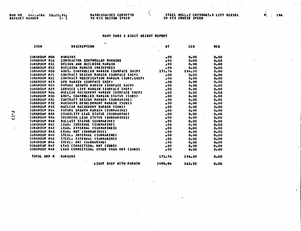
. .
(BuM NO 04r, d/Ob IOO22O31OOATASET NUMBER 1- 1
ITErI
SU06ROUP moosuaWouP N1OsuBGtouP nllSU06ROUP nlzSU8GROUP R20SUBGROUP H21SU86ROUP H22SUB6ROUP t123SU6G80UP n24SU8GQOUP M25SUBGROUP H26SU86ROLW R30SUBGROUP 1131SUB6POUP P32SUBGROUP N33
-n SUBGROUP M36SU06ROUP t$35
Lw SUD6POUP R36
SUB6ROUP h40SUBGROUP It+lSUBGROUP M42SUBGROUP H43SUB6ROUP N44SUBGROUP M45SU@G@OUPM46SUBGROUP n47SUBGROUP B40
TOTAL 6RP R
NATO-ASM-SES CORVETTE56 KTS 0ES16N SPEEO
STEEL HULLS2 LM25006Ts3 LIFT OIESE1.20 KIS CRUISE SPEEO
NAVY SUBS 3 01611 MEIMT REPORT
*OESCRIPTION MT
MARGINSCONTRACTOR COHTROLLEO MARGINSOESIGN ANO WILOIN6 HAR61NBUILOIN6 RA#GIN {RESERVEOF60VT0 CONTROLLEO MARGIN [SURFACE SHIP)CONTRACT 0ES16N HARGIM {SURFACE SHIP]CONTRACT MOOlfICATION MARCIN (SURF*SIIIPI6Fll HAR61N tSURFACE SHIPIFUTURE 6ROMTH IIAR61N (SURFACE SHIP)SERVICE LIFE RARCIN (SURFACE SHIP)NUCLEAR NACHINERV NAR61N (SURFACE SHIP)GOUT, COhTROLLEO tlAR61N STATUS (SUBS}CONTRACT DESIGN IIAR61N (SUBMARINE)NAVSHIPS OEUE1OPMENT RAR61N [SUBS)NUCLEAR MACHINERY NAR61N (SUBS)FUTURE 6ROMTM HARCIN (SUBHARINE)STABILITY LEAD STATUS ISUBMARINE)TCIRMIN6 LEAD STATUS {SU9HARINES)BALLAsT STATUS (SUBHARINEBLEAO, INTERNAL tSUBMARINEBLEAOS EXTERNAL (SUBMARINES)LEADs HOT [SUBltA@INESlSTEEL~ INTERNAL ISUBMARINEBSTEELS EXTERNAL ISUBRARSMEBSTEEL, RBT ISUBMARINE)LEAO CORRECTIONS RBT {WOS)LEAO CORRECTIONS OTHER THAN H9T (SUBS)
MARGINS
LIGHT SHI* MITH NAR61N
.00●00●OO●OO
171.76●00●OO●OO●OO.00.00●OO● 00● 00● 00●OO●OOb00● 00600●OO.00●OO.00● 00goo● 00
171oT6
1495096
LCG
O*OOOenoO* 000.00
156.390,000.000.00o* 000.000,000s 00O*OO0.000.00Ob000.00o* 0000000.00O*43OO* 000,00OeooO*OOOb00O* 00
156-35
162.52
L . 196
VCG
O*OO0s00O*OOO*OO0.00Oboo0000O*000,000.00O*OOO*000.000.000,00o@00o* 00O*00O*OO0.00Oe 000.000.000.00O*OO0.000000
0000
0.00
I
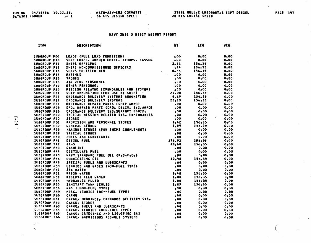
RUN NO 04t18106 10e22.31e NATO-ASW-SES CORVETTE STEEL tIUL1S2 LR25006Ts3 LIFT DIESELOAIASET NUMBER 1- 1 %6 KTS DESIGN SPEED 20 KTS CRUISE SPEEO -
NAVY SUBS 3 0161T WEIGHT REPORT
ITFH
SUBGROUP FOOSUBGROUP FloSUD6ROUP FllSUBGROUP F12SUBGROUP F13SUB6ROUP F14sU86ROUP F15SUB6POUP F16SUBGROUP F19SUBGROUP FZOSUBGROUP F21SU8G@OUP F22SUBGROUP F23SUBGROUP F24SUBGROUP F25SUBGROUP F26
~SUBGROUP F29SUBGROUP F30
-& SUBGROUP F31
SUBGROUP F32SUB6POUP t33SUBGROUP F39SUBGROUP F40SUBGPOUP F41SUBGROUP F42SUBGROUP F*3SUOGROUP F*4SU66BOUP f45SUBGROUP F4bSU9GROUP F49SUBGROUP F50SUB6ROtlP F51SUBGPOUP F52SUBGROUP F53SUBGROUP F54SUBGROUP F55SUfIGROUP F56SUBGROUP F59SU8GPOUP F60SUBGROUP F61SUBGQOUP F62SUBGROUP F63SUBGROUP F64SllBCpo(Jp F65SUBGROUP F66
(
DESCRIPTION
LOAOS (FULL LOAD COMDITION1SM[P FORCES ARPHIB FORCE~ TROOPSS PASSENSMIP$ OFFICERSSHIPS NONCOI!NISSIONED OFFICERSSHIPS ENLISTED HENMARINESTROOPSAIR UIN6 PERSONNELOTHER PERSONNELMISSION RELATEO EXPENOA8LES AND SYSTENSSHIP ANMUNITION tFOR USE OY SHIPtOROINANCE OELIVEUY SYSTEMS AMMUNITIONOROINANCE OEIIVERY SYSTEltSORDIMANCE REPAIR PARTS (SHIP AHRO)080, REPAIR PARTS {OROO OELIV. SYS.AWIO)ORDINANCE OELIVERY SYSOSUPPORT EQUIP.SPECIAL HISSION RELATEO $YS, EXPENDABLESTORESPROVISION ANO PERSONNEL STORESCEMERAL STORESMARINES STORES (FOR SHIPS COHPLEllENT)SPECIAL STORESFUELS ANO LUBRICANTSOIESEL FUELJP-56AS011NEDISTILLATE FUELNAVV STANDARD FUEL OIL (NcSCFOO.)LU8RICATIN6 011spEcIAL FuELs ANo LuSR#cAMT$LIfAUXOS ANO 6ASES (NON-FUEL TYPE)SEA MATERFRESH WATERRESERVE FEEO MATERHYORAUI.IC FLUIOSANITARY TANK LIOUIO6AS ( NON-FIJEL TYPE}#lISCO LIQUIDS IRON-FUEL TYPEICAR60CARGOS ORONANCE~ oRONAHCE OELIVERY SYSCCARGO* STORESCARGO~ FUELS ANO LUBRICANTSCARGO~ L1QU1OS {NON-FUEL TYPE} ‘CARGO, CRYOGENIC ANO LIOUIFIEO GASCAPGOs AMPHIBIOUS ASSAULT SVSTEtlS
(
MT
● 00●00
2.33●74
8.34●OO●OO●00●OO.00
24.900.69
22.30●00●00● 00● 00● 00
00421,89
●OO● 00●oo
2?6.9243.60
.00●00●OO
10.98●OO●OO●OO
3.401.0010001.85
●OO.00.00.00.00●00.00●OO.00
LC6
0.000.00
156.35156.35156.3S
0.000.00o* 00O*OO0.00
156.35136,35156.33
O*OOO* 00o* 0000000.00
156035156.39
O* 00O* 000000
156035156035
0.0000430
. O*OO156035
0.000.000.00
156.35156.35156.35156.35
0.000.000.000.000.000.000.000,000.00
VC6
O*OO0.0000000.0000000.000000O*OO0.00O*OO0.000,000000O*OOO*OO00D0O*OOo* 00O*OOO*OO0.000000O*OOO*OO000000000.00O*OO00000.0000000.000000O*OO0.00O*OO0,000.0000000.000.000,000,000.000.00
.
PA6E 197
.,
(.

RUN NO 04/18086 10.22.310OAIASFT NUNEER 1- 1
( ( .NATO-ASU-SES CORVETTE56 KTS OESICN SPEED
ITEM
SUBGROUP F67SUB6ROUP FWSUBGROUP F70SUB6ROUP F71SUBGROUP F72SUB6ROUP F73
NAW SUDS 3 DIGIT ME16HT R~PQBT
STEEL MuLL*2 Ll12500CTp3 LIFT DIESEL20 KTS CRUISE SPEEI)
OESCRIPVXON MT
CARGOS GASES ● 00CAR60P MISCELLANEOUS *OOSEA MATER BALLAST ISUBMARINES) ● 00MAIM MATER BALLAST (SUONARINES) .00VARIABLE BALLAST MATER (SUBNARINESJ ●OORESIDUAL MATER (SUMARINES) ● 00
TOTAL VARIABLE LOAD . 416043
FULL LOAD MITM MARGIN 1912039
lCG
0.000.000..000.000.000.00
156.35
161018
VCG
0000O*OO0,00O*OO0.000,00
0.00
0000
●

awl No 04/10/06 10022031oOATASET tWH8fR 1- 1
●
6ROUP
TOTAL GRP 1
TOTAL GRP 2
TOTAL 6RP 3
TOTAL 6RP 4
TOTAL GRP 5
TOTAL 6RP 6
TOTAL 6RP 7
NATO-ASU-$ES CORVETTE STEEL MULLs2 LMzsO06T03 LIFT OICSEL56 KTS OESIW SPEEO 20 KTS CRUISE SPEECI
NAVY SUBS 1 OIHT’MEIWT REPORT
DESCRIPTION Ml -
HULL STRUCTURE
PROPULSION PLANT
ELECTRIC PIAW
COMMAND AltO SURVEILS
AUXILIARY SYSTEM
0UTFITTIN6C FURNISM~
ARMAMENT
LIGMT SHIP MITHOUT RARGIN ,
720.24
238.1+
49,09
“ 66.78
114.89
100075
26.30
1324.20
MARGINS 171076
LIGHT SHIP UITM HARC2N 149%96
VARIABLE LOAD 416.43
FULL LOAD MITtl RARCtN 1912.39
(..
LC6 VCG
169.02
156e35
196.35
1S6.35
156.35
156035
156Q35
163.32
156s35
lb2e52
156s35
lblo18
0.00
O*OO
0,00
0,00
O*OO
0.00
Oeoo
0.00
0,00
O*OO
0000’
O*OO
PACE 199

.. . . . ... .. . . .. . .:,,, . . . . ...’
APPENDIX G
AREA/VOLUME SUMMARY.-)
J’

G-1
706 r
,7ZX
33 2-=-
-—
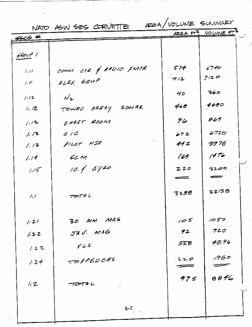
.
G-2. .
975
I
-.
em%
I

.
‘---
1
C/#&
/
.
()
G-3
//00
/36B
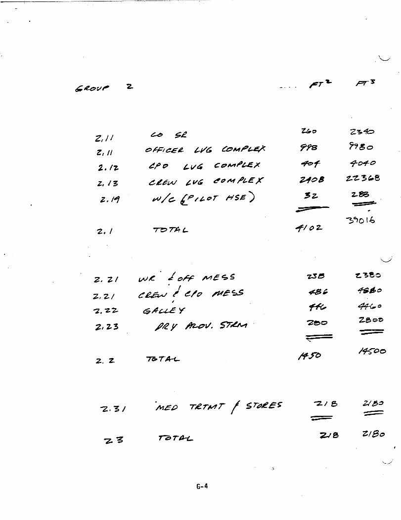
.
Z,)iz, !1
2,/z
2, i3
z, /q
2. /
z, ZI
ztz/
q, Zz
zta3
z. z
Z&o
%8
*f
~oB
3Z
Z3*
/“00
#
.4”
G-4

4
. .. . “,, .
285
“’d’
.’
0+=-7’3
/zzo
/s0
//63(3
// 222
.-/
G-5

+77A +-
G-6 -J._.,”

,.. ,.. . .. . .‘. ,,’
%.7’1
z.7/
3.74
3.7q
3.?y
3-7
3.s
3*9
. .‘L
AE&4 I+
5-L
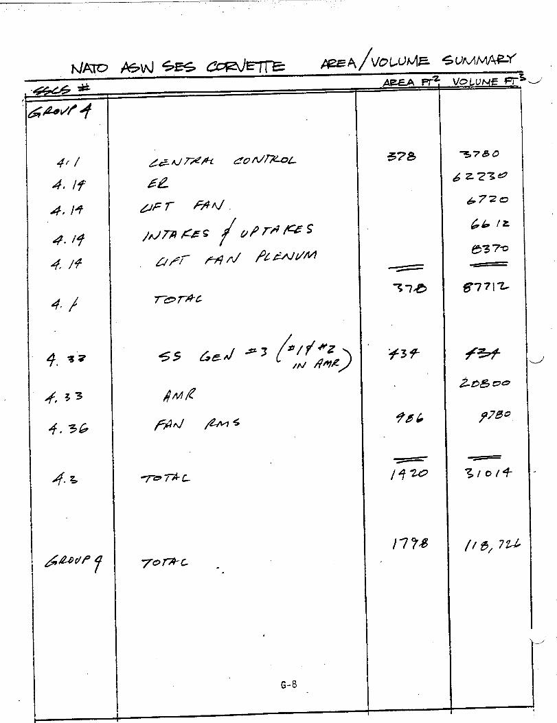
?3
33
7r7m-c
.
G-8
378
/4
J

...
.-/
g#zAJP 4
7-?= L
.
G-9 d
AE?LA H

=_-/
APPENDIX H
BELL-TEXTRON REPORT
●
.,
A!!DPROPELLER DESIGN
FOR!fE3iW!-DISPLACE\lE?,TSURFACE EFFECT SHIP
1500 LONG TONS
CO?7RACT NCO024-7S-C-5034
Repo~t 7593-950002
?icll’m%r30, 1981
. .
..4
-J.

.
. -
-.
1..
2.
.
T.ULE OF CO?ITE=S
1.1 Correlation of Predicted Propeller Performance “and Propeller Forces with Test Data .
1.2 Propeller Desires1.3 Reports1.4 Cmputer Progrms1.S Overall Index to DesignData
05SIGX AND ?ERPOR\i\NCEOF PROPELLERS FOR 150@-~S ‘NZDIL?l-DISFL4C=ST SURFACE EFFECT SHIP
2.1
2.2
2.32.4
-L
RequirenenZSParametric Analysis of Propeller Diameter,Efficiency, Rotational Speed, and XeigF,t
Selected Pzopeller Design and Off-Design Performance?4axir.u.nThrust Perf’om)ance
.4.1 Gas Turbine Power2.4.2 Diesel Fwer ‘
2.5 Propulsion Installed Efficiency Versus Fomard Speedz.5.1 ‘Gas Turbine2.5.2 Diesel
2.6 liefere~ces. . .
~pp~IJ)~x A PRIOR BELL REPORTS
7593-9330467593-902007Ts/sEs TEcH/o17TN/SES TECH/019TN/SES TECH/020
1
1
234s
15
1s15
1617171717171818
.
_. .

,. –’.,..... . ,...“ ,: .’. .,
EE=
1-1
1-2
1-5
1-4
1-s
1-6
2-1
2-2
2-5
i-6
2-7.
2-8
2-9
LIST OF ILLUSTRATIONS
Page
COMPUTED AND TEST PROPELLER EFFICI~~6
PROFELLER
PRC)PELLER
PRoPELLER
DYMNIC FORCES“7
PRCJECTED VIEW MDS-1500 PROPELLER8
BLADE SECTIONS EXPANDED VIEW9
?ROTJLSIJ’EEFFICILN~ iEFWJS SPEED10 “
FUEL FLOW RATE - OSE/Tl’OPRCPELLER/=GINE11
D;-:,GyERSUS SpEED, 1500-LT SES19
}!2S1500 PROPELLER P.APJV’ZTRICPERFOWl&NCE20
BL.tiIEKEICW VERSUS SIZE21
}!3S1500 PROPELLER22
KIC 1500 PROPELLER (50 PERCE>T SUBNERGED)13
}!2C1;00 FF.OPELLER(100 PERCE\T SM}’JRGED, VENTIL~T:D~ 24
14MI}fA!TFN.USTOX CUSHIOS - LN2500 EXGNES, NICP2s
1!431WT!THRUST OFF CUSHIOS - L}12500ENGINES, MCP26
MAYII?J1THRUST OFF CUSHION - SCAN ENGINES27
.
.--’
ii
LIST OF TABLES
W7ber WE
1-1 K)S-1300 PRO?ELLER DESIGN AND hlACHISERYP/41W~TERS “12
1-11 INDEX TO DESIGNS 13..
2-1 SA1l’REQUI!?ENE..TSFOR }lDS1S00 PROPELLERS 28
2-11 SEc~Iox oFFsiTs jLYDPILA\FOR,~f}~s ljoo pRopELLER
D“I!.!ESSIONFOR 29
‘.>
. . .
.
.
---”
iii

. .
--/’
.
. . .
-,
-“ ‘
7S93-950002
E3eflAercq2aceFi7Ti’T7D.,s,m ofle,!.c~ I.-C
1. PROGM.~tOYERVIEK ANI S’JINARY
Computer programs were fomulated and used to design partially submergedsuperca~’itatingpropellers (PSCPS). These programs were also employed
to’perform preliminary structural design of the blading and to predict
. propeller off+esi~perfomance over a range of submergence. PropulsiontF,rustwas conputed for installed propellers and was compared to the shipdrag, taking into consideration the propulsion engine characteristics,lesses, and various machinery arrangements. Pr&dicted propeller non-
dire~sional characteristics and propeller forces and moments werecozpcted and correlated with test data, in a limited effort.
1.1 Correlation of Predicted Propeller Perforamceand Frcp.ellerForces with Test Data
A critical perfonna~ce correlation was made to validate the off-designper~ormance results of the SSCP computer progrm. This progrm. was used
for most of the off-design performance predictions during this study.T~e co:ielzt.icn cor.?zredthe cozpzted predictions of the SES-IOOB pro-peller design with model test data and full-scale test data. The results,which were favorable, are contained in TX/SES TECW017 of July 24, 19S1,
J figzres 9 and 10. Figure 1-1 of this r,eportis a copy of Figure 9,whichskz..isthe ccnparison of pfedicted and test efficiencies.
.
The work on correlation of computer-predicted forces with model testLaza, xhicb ~as inclu~ed in the original task, was deferred after itbecane appz~ent that riexpro?eiler ’designs would b? required .f$.raddi- .tional ship configurations. Before the deferral, computations weremade of both steady and fluctuating vertical and horizontal propellerforces, for the B6620 propeller, which was designed for the 900-longton (LT) gross weight Medium-Displacement Combatant (MDC) SurfaceEffect Ship (S2S). These results were shorn on pages 2-53 through2-S6 of tl-,einitial report of December 1980. Using,the available SSCPcomputer program, detailed time histories of fluctuating forces for thissame propeller were co~puted, as well as the blade loads for various
forward speeds. Both were computed with and without the influence of
cus3ion outflow at the propeller. Computations included shaft inclinationz~,glesof O, S, and 10 degrees. These partially completed dynanic forceresults were presented in the program oveniew in Septenber 1961, and .are sho~m here as figure 1-2. The corresponding influence of cushionflow and shaft inclination on averaged propeller performance is shck-ncr.pages 2-s7 tkiro~gh2-60 of the initial rejort of December 19S0.
.
Correlation work was completed to describe the geometry of the bladesections and blade planfons of the David TaYIGr Xaval Ship Research indIJe<;elcpnentCenter (DIYSRDC) 4281 and 4407 highly skewed propellers;
.-./’
7S93-950002 1
*
13eiI*p~ce k-~0wS13n 0! Yextfor, Inc
parameters included local skew, thickness, camber, and angle of attach -at several radial sections. This nade possible computerized performance
predictions and force predictions. It was planned to.cmpare predicted.
performance and forces with available model test data, at various bladerakes snd shaft inclination angles of the 4281 propeller and the 4407propeller. No conputer nms were made, however, because further correla- “
tion t~rk was deferred by the custuier. .
1.2 propeller Designs ‘.,
Fi\’epropeller designs were prezared and investigated. Four of these were
new designs and the other w= an existing design scaled to match the ?4edium-Dis~2acenent Surfzce Effect Ship (MDS) thrust and power requirements.
These designs were made for various SES vessels, which ~ere studied by the
XaYy as follo~s:
a. coastal SE’S,400-LT, full-load displacement
b. \?e~i~.Di~placement Combatant SES, 900 LTx
c. t4ediur,-DisplacementConbatant SES, 1600 LT
“d. \fe~~~~.-DisplacementCombatant SES, 1600LT (s~]ed SES.1OOB../”
propellers)
e. Mediun-Displacement SES, 1500 LT.
lTfieCoastal.SES propeller is a fixed-pitch design; allcontrollable-pitch propellers. Ship drag was suppliedFigures 1-3 and 1-4 show various views of the HDS 1500table 1-1 Iists the design and machinery paraiieters.
the otkers zre .by the Sa\y.propeller, and
The off-design characteristics of the Propellers Qere computed and matc~.edto a
●
●
●
●
●
variety-of,rachinery
Coastal SES: CODOG
MDC 900: COD14G
!4CD 1600: (a) CODOG
. .configurations for the various vessels as follo;;s:
and [b) only two gas turbines
Mls 1s00: (a) two gas turbines or {b) CODOG.
The gas turbine used for the sriallesttwo ships was the .411ison57@K.+jfcrthe larger SES, t},eGeneral Electric (GE) L}!2500was used.
‘d’
7393-9S0002

\Sell Aerospace
fkson of Ter-tan mc
.-/
Propulsion efficiencies versus forward s?eed of the new designs ofpropellers were computed using the available PITCHOPT program (seesection 1.4). The propeller installed efficiency and required pitchsettings for the ?fDC1600-LT vessel are shown in figure 1-5, for bothon-cushion and off-cushion operations at light weightj in sea state 3.Excellent propulsion efficiencies are maintained over the speed range,using the coct~oll=ble-pitch feature of the propellers. Figure l-~ alsoshows the effect of operating off c=hion k’ithone propeller and one engine.Although propulsion efficiencies are reduced, the engine efficiency isim?rcved, reducing total fuel consunptiotibelow 17 knots [shown infi5wre 1-6).
M shokm in figure 1-6, a significant improvement was noted in one-projelleroperation over two propellers for the MDC 1600 LT; however, no ixcprovenentwas noted in the }!DS1500.
“.1.3 Reports
Six reports sere isszed to the !iavy. AS requested by Xavy re~resentativesat the program review in September 1981, copies of the earlier reportsare included in this report as appendix A. These reports were issued as
““-J follows:
RE?CF.T
7595-933045
. 7593-902007
TS/SES TECH/017
TS/SES TECH/019
T!i/SESTECW020
.7593-950002
DATE
12/s0
S/81
7/81
9/81
9/81
11/81
In the first report, a study
VESSEL
400 and 900 LT
1600 LT
1600 LT
1600 LT
1600 LT
1500 LT
Design ant?Perf,ac.znce
Design and Performance
Expanded ?erforzance.
Efficiency versus ForxardSpeed Two and One Propeller
Scaled SES-1OOE Propellers
Design and Ferfonnance
of propeller structural design criteria andav,zilablerater;als was included; which led to the selection of titanimalloy and a design stress of 18,000 lb/in2. These ”characteristi~s wereused for all the new propeller studies. For the FIDS1500 propeller,.:a.ter the scaled SE.S-1OOBstructural design.had been studied, a10 percent
● overspeed broaching requirement was added to the structural criteria, aswe]] as a j percent thrust overload.
d
7s93-9S0002 3
I
●
. .. . ... . . . . .
1.4 CoRputer Pro~ams
Several computer progrms were used in the propeller desi~ and performance
investigation. They included the following progrms:
SCRP
SSCP
PIT’CHOPT
.
USEs}j!?LEOUTp~
..
Design point Report 7593-933046,Page 2-39, 2-40
off-design, optimization and .
p=opeller forces
Report 7593-933046,Page 2-41, 2-42, 2-45,2-44, 2-45, 2-46
~!axi~,umthrust versus engine limits} lY/SES TECH/017,
gear ratios and prcpeller pitch table 1
setting
kf5W4n.Jrnmropeller efficiency versus TS/SES TECH/019,
OnA winir.lml fuel flOW table 6 ~.L“,=A~81’--- r-forward s?..., ...-..-...—. -—— .with one or two engines, consideringengiI?elir.its,pitch settings, andca~itation limits
The SCRP progr=~.Kas derived from the SCPRP progrm listing for design of
supercavitating propellers, which was originally fomulated by Hydronautics
Inc. .The Bell version was reformulated for t~’pewriterterminal controlon an IBN conputer system (rather than card deck control on the Control
Data Corporation system]. This work was described.in the first report. A
listing of the new progrm with someadded features was submitted to the
Navy: the reformulated program exactly reproduced Hydronautics samples.
Bell has proposed changes and additions to this program and its documenta-
tion to overcome certain existing limitations. The program revision would:
a. Eetter define peak efficiency perfo=,ance and face cavitationlimits
b. Modify t3e
to thle conventional
C. Facilitate
●
skew and rake reference from the blade trailing edge
center chord reference
terminal input
>
jj93-950002
●
‘---’
d. ~cr.~c:enonventilated ?erfomance
e. Doc=ent progrm changes, options,
new listing to the Navy.
1.5 Werall Index to Design Data
Table .1-11 is m index to the principal desi~- featuresresults for the various propellers.
,.
and furnish a
and performance
. . .
759-3-9S0002
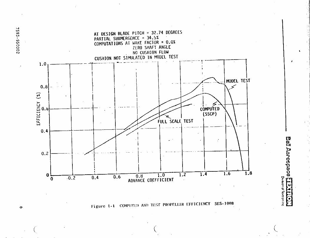
4ulu)wt
1.0
I0.8
(3.4
0.2
c
AT DESIGN BLADE PITCH = 32.74 DEGRCESPARTIAL SUBMERGENCE = 34,5%COMPUTATIONS AT WAKE FACTOR = 0.0% .
ZERO StlAFTANGLENO CUSH1ON FLOW
CUSHION NOT SiMULATED lN MODEL TEST..——-.— .-- .-.-..-1’” ,...-.— .—.- ?- 1 r
‘TT
—-—--------1
.. . .}
i
_—. —.—
——-
—-- -/
J___.0.2
(’
-.
L-......-.
~ 1. _..~ ........_..umDELT)
----
7A--– [“““’’””-””I
II
““1I
..
-----
--.——
“ I l\
.. ---- ‘P‘\...-—II
0.6 -0.8 1*L 1.4 1.64
ADVANCE COEF:i:IENT ~
Figure 1-1 Coml”rl;l) ANI) TEST PROl>Fl,l,l:ll l:11:1CI I:NCY SES- 100B
I
,,
.

....,
.::...
...
...
..
..,..
.,,
_/
-.
.
------.-
-----------
-------’-
---------
----
-------.-
—---
...----’
-----
.’--
—.-.
—-
-----
.-----
—-
--.---—-
--.——
-----
-----“.
..
.
o=g
.-4
_,---------,.r’+@=’
~+~--—
-../7
—..-..------.
—7 .
......--
----
.2~:;
o*
--—
——
—._—
_,..
..
“a
——
—_,
.;
i;——
—..”
8
——
——
..-.
——
—.
.--—
—
-
‘-4’
s
nLi0.
..
----..-.
uJwz
.
.r%
.
0
.
_.—.T.
..
w)
3NOd7V)Ilti3A
--,..
(870001)
.--”.-.
7593-9500027
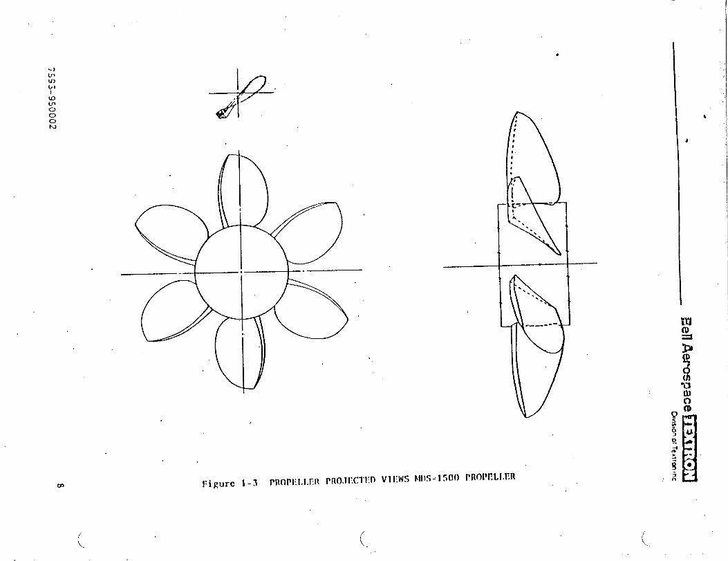
—.
—.:
.....
,,
●
ccL-,.,
C=&c...-.
‘u”
ijS3-550002
s
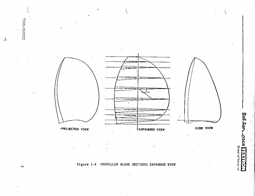
...
....
..
......
..
.....,
.,
Ml
Aem
+ace
~r~
Dw
SIO
no
fT
efiror.
Inc
-./J
.
.
‘d
“7593-950002
..I
..
.
9
-.
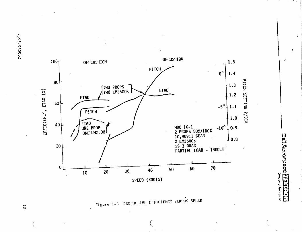
.
PITCHSE~lNG
P/DiA
●
Lbo
c...-.zu
?z“-Ln,..5t.-1
~j93-950002
w“
10
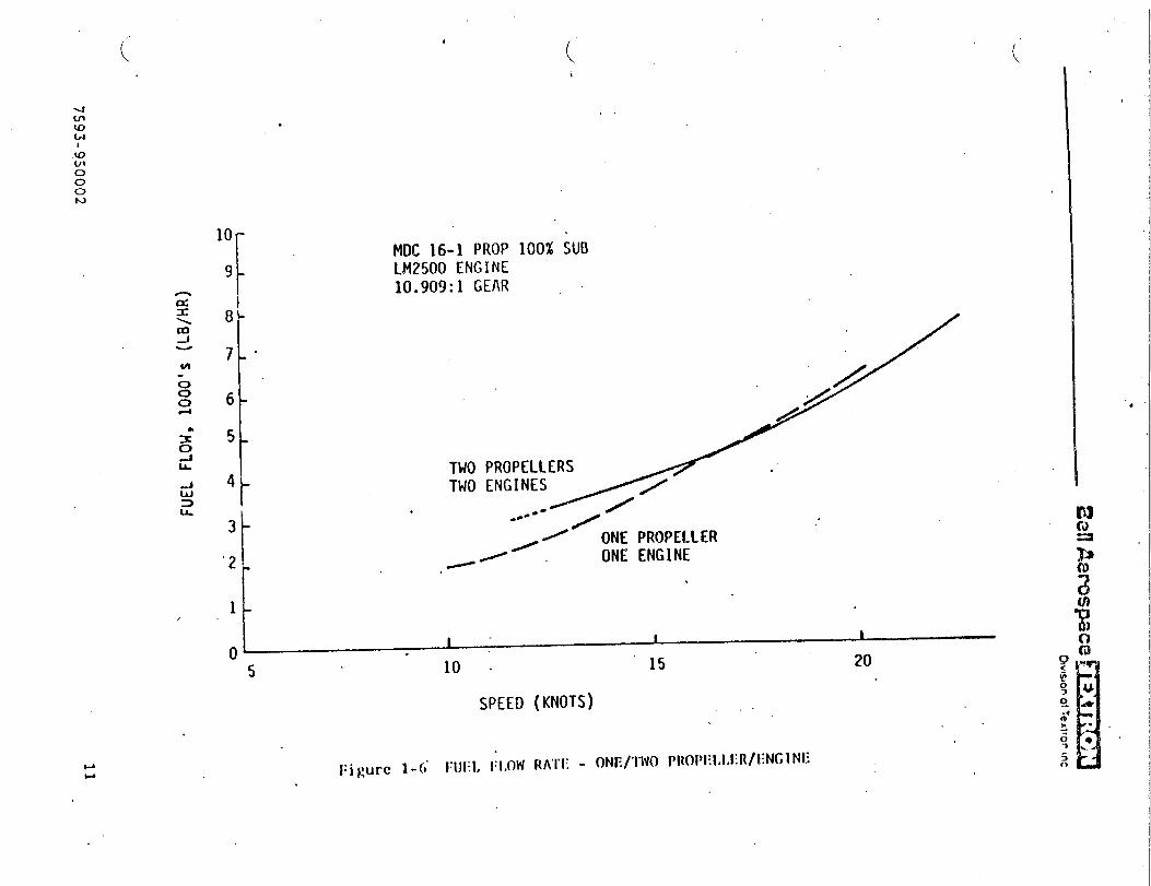
.
IE3iE
El
Ml
&?
rc#sp
ax3
1
d.-./-
.
-#00
.
.
.
(WS
7)s,0001‘MO-U7304
\
7593-950002
o
wowwnm
I
...~-<Ct11

_ .. .. .T.. , ...*
TABLE 1-1
MDS-1500 PROPELLER DESIGN AYD M4CH1SERY PARAMETERS
Type
Forward Speed (Knots)
mTUSt (Lb)
Dianeter {Ft)
RF?!
Ex?mtied Area Ratio
Hub Dianeter Ratio
Sm.ber of Blades
Radius of \!axChord
\ Design %nding Stress (Lb/ln2)
Werspeed (Percent)
Thrust Margin (Percent)
lR.=C: ~cad Factor
Blade }lateria]
pitch At 0.7 Radius (Ft)
M\’ante Ratio
Skex, }~idChord (!)egYees)
Rake, }jidChord (Degrees)
Su&ergence [Ventilated)
On Cushion (Percent)
Off Cushion (Percent)
Poser - GE L~!2500!4CP(HP)
Reduction Gear
Alternate CODQG
S.4CM240 V16 RJR Continuous HP
Diesel Reduction Gear
Controllable Pitch, Supercayitating
’45
86,8s6 .
14.5
240 -
0.50 ~
0.40
Six
0.70
18,000
10
+5
1.75
TI-6.41-4Y
21.915
1.310
0
8
so10024,000
1s.0:1
S600
11.5:1
w
739S-950002
●
12
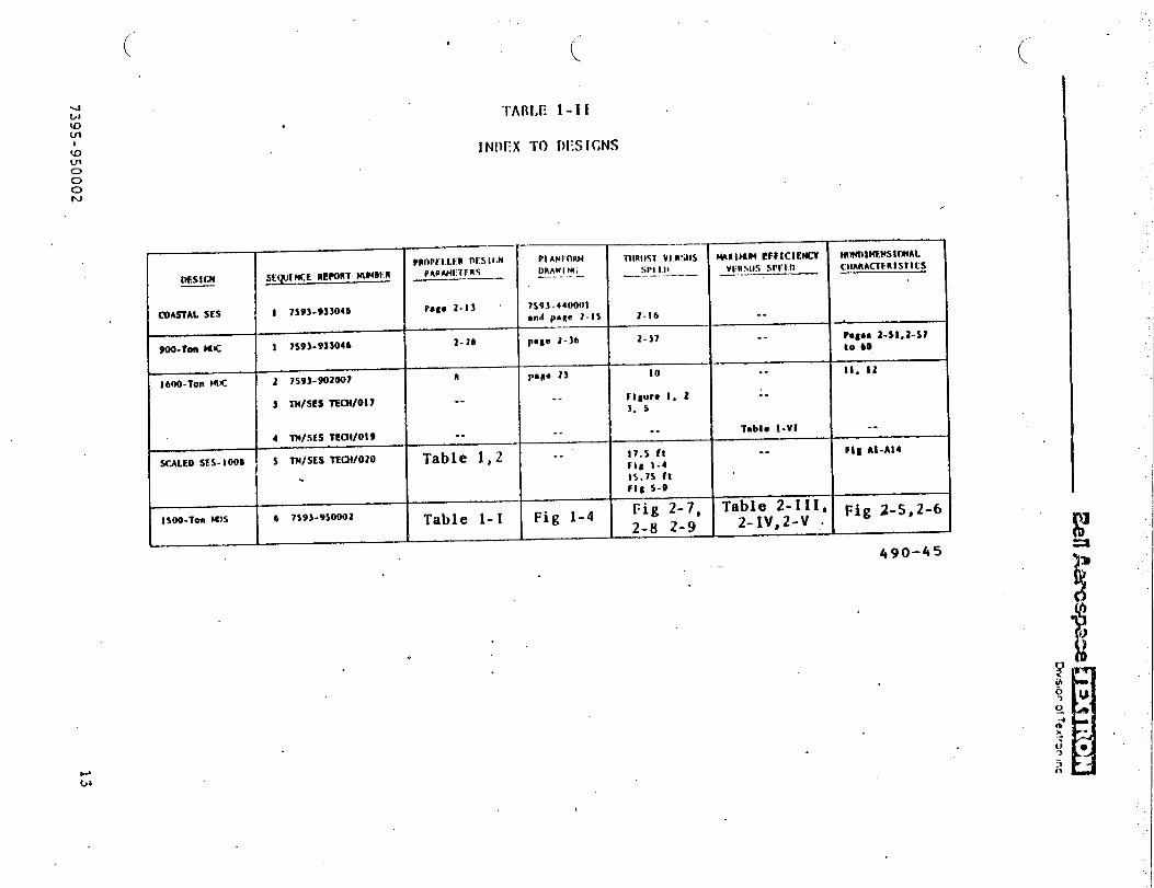
:..,,
.’..
..
‘d
.
.
.
x!..=z
\
7395-9S0002
I1-
1
——
ut!e.u
I
..
.

../SECTION 2
DESIGX .KYDPERFOQ-~i~.KCEOF PROPELLERS,FO?.1500-TCX }EDI’J.l-DISPL.4CE!iE37
SURFACE EFFECT SHIP
‘4’

,., ..-.,, . .. .. . .. .. .. . .. ... . ......,,. ,’” .“ ,.#
2. DESIGN )&m PERFO!WANCE OF PROPELLERS FCR 1500-TOS}EDiLT1-DIS?LACL~lEhTSURFACE EFFECT SHIP
A supercz~’itating,partially submerged, controllable-pitch propeller was .
desigr!edfor the Medium-Displacement SES (NDS] of 1500 long tons (LT) gross
weight.
The vessel parameters for this study were defined by the Nav}*. Propulsionpoxer xas provided by two General Electric LF12500engines. An alternateconfiguration cor;~inedtwo diesel engines (used for off-cushion propulslor.
only] with the gas turbines (that is, in a CODOG propulsion system.
arrangement].
2.1 Rec;~irenents
y=~~e ~.I lists the basic requirenerttsand engine ratings for the propeller
design. The d=ag cur~’essho%n in figure 2-1 were supplied by the Navy,and a~e based on model test data. In sea state 3, the ship is designed to
o;erate at 45 knots, cn cushion, with a full-load displacement (FLD] of
1S00 LT, and at 20 knots off cushion at the same weight. Alsorequestec?was the on-cushion, top-speed pe?fornance in sea state 3, with
\J’ a 105O-LT displacement.
For t!-.ealternate configuration, SAC!;diesel sngines were selected becauseh+ and suitable power ratingS.O: theii IiSht w~ig,t.
eng
Two SAC\!?40 Y16 RVR
i>e~ xere used, one on each propeller,’and were rated at 5600 metrichcrsepoxer, co~,tinuouspo~er.
TY.ereduczion gear rztics were to be selected as those necessary to matchthe engines and propellers. ~
2.2 Parametric Analysis of Propeller ”Dimeter, Efficiency,Rotational speed, and Keignt
A parametric analysis was made to size the propellers, using the SCRPconputer program in its preliminary design mode. Diameters from 11 to
17 feet ~ere investigated, at the 4S-knot point, with a design thrust of
67,000 pounds per propeller at 50 percent submergence. A naxin~i ~hrustof 92,000 pounds was input for structural computations and the design
blade stress was 1!3,000lb/in2, using titanium material. This is thesane stress t!-.atxas used for prior designs in this project.
Figure 2-2 shoxs the parznetric results of efficiency versus di=neter.Tae effects of design rpn on efficiency and ?itch are also shown. At e~ck
‘d
7395-950002 15

~n level, the efficiency increases as the diaiieteris increased, until apeak value of efficiency is reached; thereafter, the efficiency declines.
Apro?ellez dizseter of 14.S feet was selected, which was the maximumefficiency that could be obtained without the blades overhanging the side-hull at the trmsm. The selected mopeller has a design point efficiencyof 72 percezt, and a level of 240 ~m was selected.
Fi3zre 2-3 SF,OWSthe effect of diameter on total blade weight. The design
is for six blades Znd, as can be seen, blade weight is almost independent
of rpm. Hub weight (not included here] is expected to constitute most ofthe total p:gpeller ~eighte
E~ti~ation Of total propeller weight is planned for the next phase of the
design project. The selected design has a preliminary total blade weightaf about 52S0 ?Qu!?ds.
2.3 Selected Frcpeller Design and Off-Design Perfonance
After the parm.etric study was made to select the design point, final\ design Wzs COK?ti~f2d with the SCRP program, using the ,sanedesign point
ihrust and “ir,putparameters. (See table 1-1 for the principal propellerdesigx z!??P42cY,inerypara~eters.) These values are the chosen inputs tot}.ecar>uter prsgran, except for thrust, pitch, advance ratio, skew, and‘e,rat. which are p~ogrml outputs. The ge~r ratios are found by matching
ezgi?e to Frcpeller characteristics.
Corple:e inpus and OU:?UC data for the design are gi~’enas t“able2-11.T}.efirst page of the table is input data and subsequent pages are the.output data. The second page gives overall perforr,ance,with detailedhydrod>~amic and geometric data at se~teralradial stations. The next fourpages show the geoEet~ of the blade sections and planform, and the finaltwo ~zges show the section pressure coefficients End Pressures- Headin&sfor the printout colums are defined in reference 2-1. (Section 2.6).
Figure 2-4 shows the projected and side views of the propeller-blade, withthe exparic?edoutline. The txo views are a plot of the geonetric dztagiven in table 2-II, which does not show the blade trailing edge thickness.
.
Figures 2-S and 2-6 give the nondimensional performance of the propellerat 50 and 100 percent su!xner-gence,over a wide rsnge of off-design advanceratios and pitch angles. Values for these plots xere obtained fron theexisting Eell SSCP conputer program. Correlation of the progran’s off-de~ign results with test data is sho~m in the sumary and in the appendix.
“L=”
o
7395-9S0002 16
w
,. —. .. . .,,
d“
2.4 Maximum ~rust performance
2.4.1 Gas Turbine Power
Maxiram thrust versus speed with LV2SO0 power is compared to the drag infigures 2-7 (for on cushion) and 2-8 (for off cushion), with a 15.0:1r~iucticn gezr.
. .Results are o“ctai?ledby applylng engzne arcd propeller
characteristics to the NE~FROP computer progrm. Enough thrust is availableat maximum continuous power to operate 1500 tons at S2 knots in seastate 3, and to operate 1050 tons at 57 knots. Therefore, there is amargin of thrust to operate at 4S,knots at 1500 tons (full load) in seastate 3 at the propeller design pitch. The propeller face cavitationli~it advazce coefficient set to 9S peycent is shohn in figure 2-7. Tke facecavitation linit shorn was determined by an advance coefficient of 9Spercent of the peak efficiency ad~ance coefficient.
The effect of gear rec?uctionupon maximum thrust performance was studied,using 16.5:1 and 13.O:J reduction gear ratios. .Yaximuinthrusts and fomardspeeds were dscreased xith a 16.5:1 reduction ratio. Maximun thrusts wereincreased using a 13.0:1 gear ratio, hut propeller rpm limits were encoun-tered at -lower fowzrd speeds, so that the design was not feasible with
& this gear ratio.
2.4.2 [,iesel Pcwer
Ki:h alternate diesel pcwer, figure ~-g shows t~e maxinwm thrusts available
for off-c’us?.io.noperation. There is a considerable r.arginin t~trustat20 knots, using the S.401240 V16 R\”Rengines at S6C0 co~tintiozspower afida 11.S:1 reduction gear ratio.
2.5 Propulsion Installed Efficiency Versus Forward Speed
2.5.1 Gas Turbine
Tables 2-III and 2-IV give po~er and propeller parameters for operation insea state 3 with thrust equal to drag at 1500 tons and 1050 tons, respec-ti}fely. The propeller pitch is set for the best performance at each forwardspeed. These tables represent operation with gas turbine limits and a1S.0:1 gear reduction ratio.
Table 2-111 S}.OKSthat propulsion efficiency varies from 0.607 at S knotsto 0.711 at 4S kncts for the full-load operation at 1500 tons. Thepropeller pitch is -12.S to -10 degrees off cusSion to on cushion, thenincreasing to +5 deg:ees at a top speed of 50 knots. Above SO knots,engine rpm, power, and prcpeller overspeed rra limits are exceeded.
.-J
739S-950002 17
At 1050 tons (see table 2-IV),the available drag data only covers on-
cushion performance, starting at 22.5 knots. Pr~eller pitch setting
increased from -lo de~ees at 22 knots to +7.5 degrees at 60 knots; above
60 knots, engine power and rpm limits are exceeded.Efficiency Increased
from 66 to 74 percent over the usable speed range. Top speed IS approxl-
. .
nztely 60 knots.
Table 2-v S},OWSthe power and propeller parameters for off-cu~hion operationwith diesel efigines,with thrust equal tO .d=g~ at 1500 tons, in sea state 3.
.4gain,“propellerpitch is set for.best perfom.ante at each forward speed;
pitch increases from -15 degrees At 5 knots to +2.S degrees at 20 knots.
Propulsion efficiency increases from 0.614 at 5 knots to”O.683 at 13.S knots,
deceasing to 0.608 at 20 knots. Although the propulsion efficiency is not.
chsrged greatly for diesel compared to gas t~bine. ope~?tlonnthe engine
decrezses considerably. T~lcal gas t’uTbineS,.elcor,s~--.ption~?e~~fic ‘-cons’~.ptiona: 20 knots would be 0.70 lb/hp/hr, coqared to 0.40 lb/hp/hr
for the diesel.
2.6 References .
;
‘J
. . .
7-39S-930002
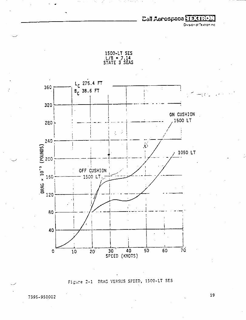
“DRA
GX
10->
(POU
NDS)
o—
—.
I——,.
—.
—--
,_.
.-.-
—-
!
.—-.
i-..—..L-
1
-n
P.
.+.—
..
..
..—
-
la~
<
--T
1
Io
n.--
----
:._..
.—
-—.
~-c-.—.
1-—..
- L–-——
——
—
;1i\
Ir-~,
11
i-~
i_
J-.
.–.!_
—.)1
..-
4—..+
—I
——
---
1-.—
—),
‘1,
,:I
i‘t
I-
:.””
-.,
-.-
1..
...
.—
-.
j_..
:
—~.
...
—-
...-
,.
~I
I1,
iI
II
I
\
----
-!~
>,
;1
-—
.—--
-
~.
\*~
i‘
-1“
---~
‘[~
I-.
-.i.
t‘
“’I
I.-..-.
..;,
-‘o
——
--—
m -cl
m “3 .
—-.
i--
--I
.’‘$ f A
‘5
c)
Ii i
“. \
rnm LA
--
I
0 r-
-4\ i .,,
r, t“’
.. .
, ,,.
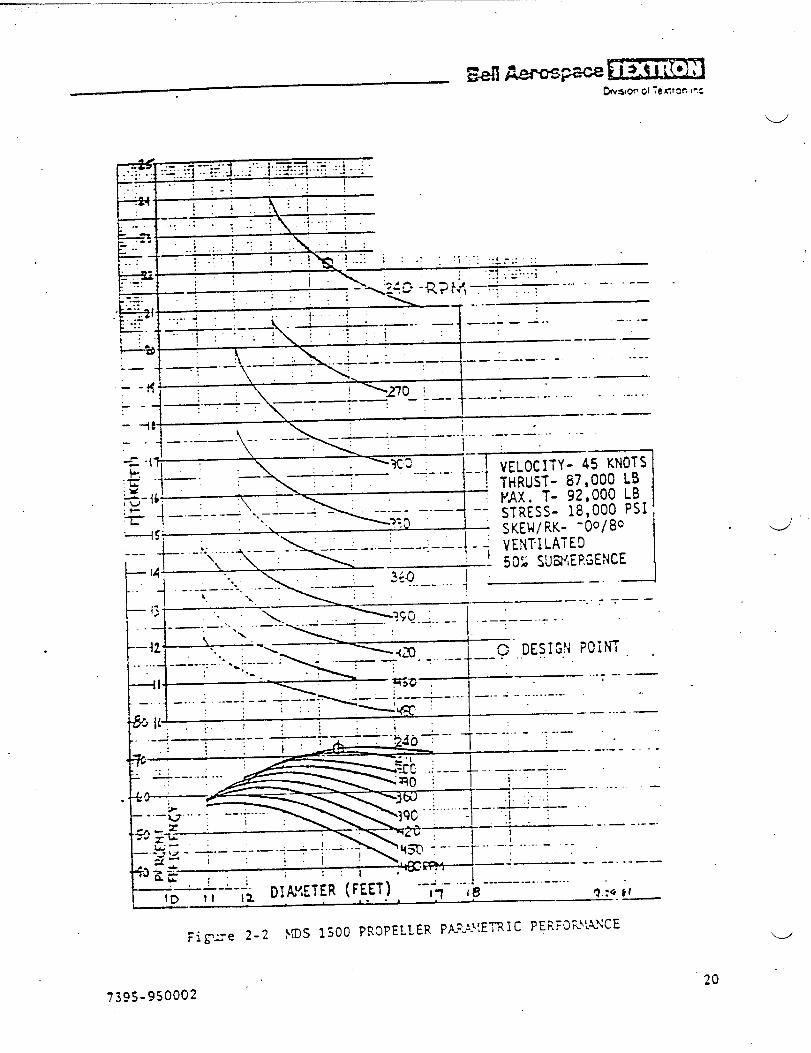
—— .-<[ . ..??’:’;:.:::.-:::j,.,.:”””.\””;::\;~””’::.,+.:.::.:... . ;. ..’.,
I.-.
,“. -;’:.-.! : ; .;.:< KT---,;
: ..! “i :“::~:;: ;:. .—
;“ i ><l+o .R++LZL... - -- --—:.. ::: I . . ..’. !:.” -,.—
. . .. . .1. : ..: .t -— -- —
i ‘--!V” M ‘ ‘--- - ‘-- ----—-~
-_--_:- -. ----
:—I — .- —.
.-_- —- .--—.--—- -— --------
--....
—--. .— —
\-. -i ---- –—-/-- - --–\–-”--—-
1.-.....-- -—-——. . .-
\ \I_ , >
_.“{1!F..._: -WC :
~- — ., ---- .-. I ‘ . 7VELOCITY- 45 KNOTS‘-’!THRLJS~-~;’:~g kg:=
—‘L1 ‘- ;T’iki: 18;000 PSI.45: \ d
---t“
. -.“.’....<.. ~---r’r ; j -:, &;;i+E~OO’80\. I
— 502 SWVIEP.GENCE !
L.. d -.--– ---”-. ---–- ----I ’11 “. Xo\ : .... ..... { L—– .--J
F- 1 ‘ ‘“-~IJ ~ . . -\~,,, , +-:-.--””’ ‘ ‘---—
PJ*:; ~~ I —— ...-
J{{, ,:.. .li. i i.~1 ..-.—._-. &.._ —-- *----- ----L. .-1—----– -+ T-- -- I— __ .-. ---
{%3 ;++--,.-
\\-;: “-:---”t-”-T””----”-- -----. . .;_~\q.: .......
--~,--- ““__
I \ >U= --- __+.. .-.; . ---- --L.-,$3 - —-- –--—-7-—:’ —“-: -I -%=: I ‘ = ‘&.&__+_&+ ------
. . . .
—
- ----
- ——
k..a G
{:i
ID-H ,2 DIW,EIER (FEET) --~;---i!---------...... .—-----
. . ?J.:Gkf—- —
20
“u
w’
..
7j~’j-950002
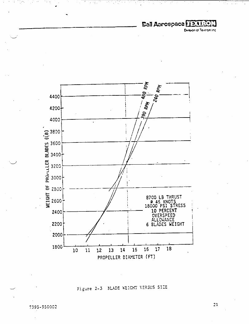
.’ ....’ . . . . . . . . . ..... ,
4
w
‘d
4000
.
if‘2 3000L
240(
220C
200(
180(
------=’4+
Y I I 1 I 1 t i
10 11 12 13 14 15 16 17 18
PROPELLER DIAHETER (H)
..--’ Figure 2-3 BLADE WElGh7 VERSUS SIGE
21

“.“e
“.!
.
I
I
.,
)
1’\L \/-:\
,r..
I /. ‘‘\-., -1 /
,:i !-:.4..,_
LE
t1/1
..-, ,,“---
i!,
* .-+
.. .. .
.
.*., , .
i.>\
;.● .4
/
.
\
..* \\
)ILE
..L’_.—- !
I
i
I
IIi
““. ,I.&fibhidl
I
SIDE ‘I
1’PROJECTEO VIEM IN.PLANE OF ROTAT1,ON, ‘
,PL.ANEOF SHAH
k:t,.
1 Y:;f
“d ..;-..*:.
I
N-1~- t 1 1
-1*() 1) 1.0-1.0” 0 l-o
_i~—L‘o -2.0 -1.0 0 1.0 2*O
FEET
DVIEW ‘ ,EXPANI 1
t
I.
t.)tJ
(-./
(-(.-
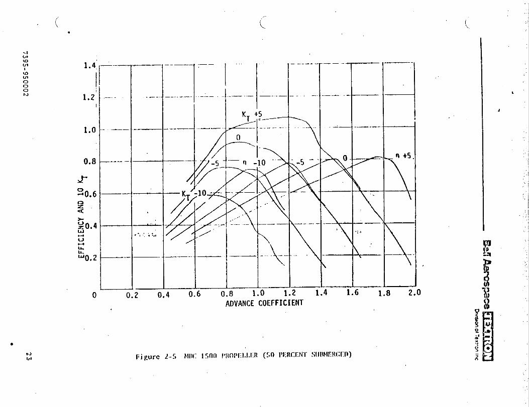
.._J
“’d’
-T, —.$
/I
e
1.
,/.
____:._~
,,.,
.-p
,:
I
II
&I
1i
~;
iI
I
●
ccL:.,=z.--
d
25
●
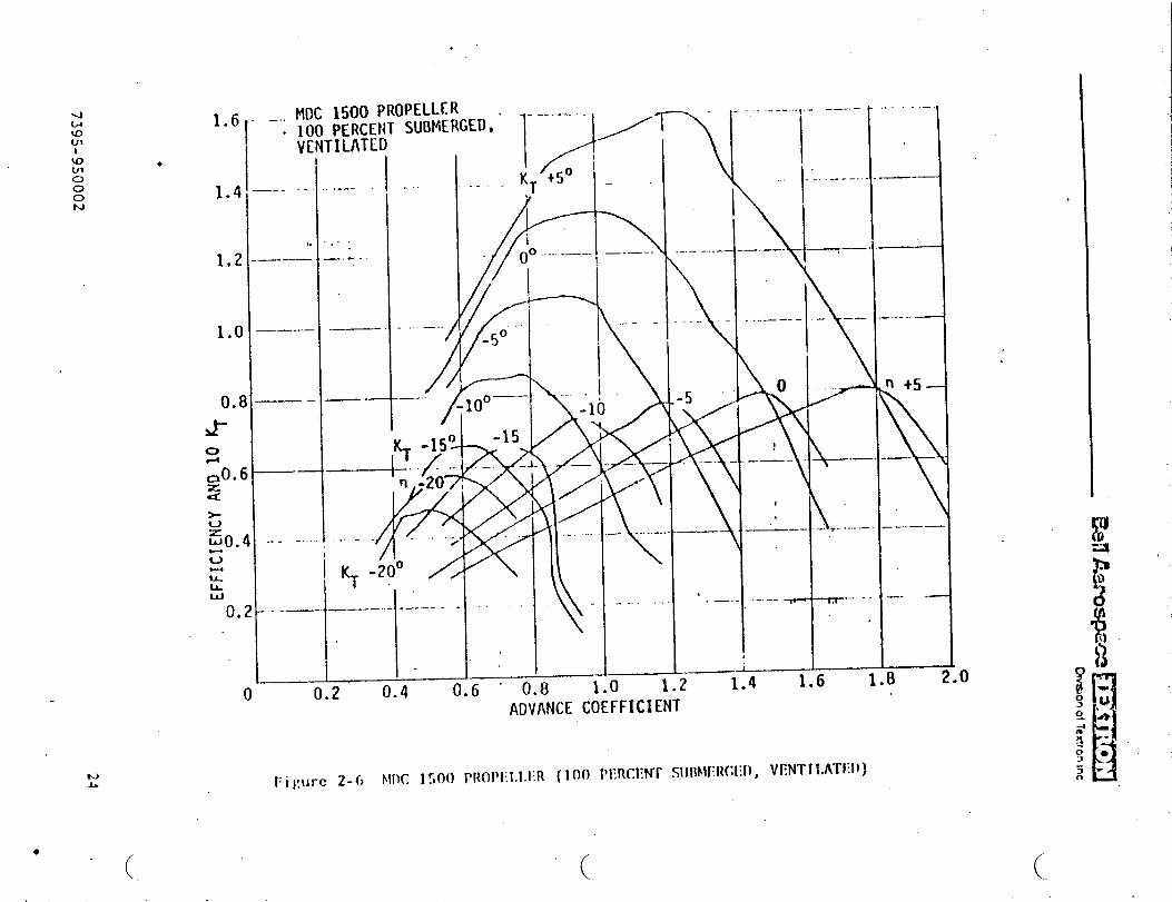
w(J1
●
KJ
1.2
1.0
O.tJ-
vILu-W0.
.
—--- -. i---- I -
II,.,..:
1.6 . . .. MDC 1500 PROPELLERI
. 100 PERCEt/T SUBMERGED. ”VENTILATED
I I
~_A,T
-KT+50-1.4,
_—
——-—
——
—.
------
_—
1-----.—.-...—.-\//—..
k“ I
0. .2
ADVANCE COEFFICIENT
-.
--- -------
\
.
-5
F
.—
----- .~.- ---. —
!1“..,____.
\
-—. ,—.__—._..—.——
~ ~
0 ~~~
.—- -’ —
I
——— - *- --.--—
1----.----
1.4 1.6 1=8
I....-—.
. ... .. —
n +5—
k
—-..—-—
—. —
.
0
(. (..

.-/
1500:,(K$ \\tiSES
STATE 3 “SEAS
KDS-1500 PROPELLER50% SUBMERGED2 LIU500 WGIHES lTXP- -. GEAR RATIO 15:1 ..
J
36G-
320’
280
t
Io
x
II
40 ‘
I
MAXIMJtlTHRUSTCON~INUOUS POHER
ION-CUSH1ON1500 LT
//
/ i
OFF-CUSHION’ \1500 LT \
,
,050
0°
.d- 10 20 40 50 60 -70SPEED &kOTS) t!.s.$}aqk
}I
LT
“JFigure 2.7 !.KXIWJI11-.?.uSTOX ‘CUSH1ON - !J125.00ENGiYES,
2s

.—— ——– —–—–,..
.
1500 LONG TON SESLIB 7.14
STATE 3 Sm..
14DS-1500 PROPELLERIOOZ SUBMERGED
-.2 LY,25G0ENGINES !1:?
GEAR RATIO 15:1 ..
.
n
320;
Ii
,.I
160
120
80
40
0
PAxIWM THRUSTSCO?;TI?{UOUSPOWER
,&
. ON-CUSHION, 1500 LT
/’/
DRAG, /“
/
-10°/
/-/
PITCHO./””.’
/_~~~~— —.—- ,—10 20 5t 65
SP:!!’(KJl )
C)FF-CUSHICN
-: -,..,. q 8 $(UIW?l THRUST OFF CUSU!OS -r.~-.e --
1050 11
,
I.:.
I
.!
i
t1.
,
I
i
-J70
‘J
“u”
7395-950002

.
1500 LONGL/B
STATE
I’13S-1500
TON SES7.143 SEAS
PROPELLER “100% SUBMERGED
2 SACM 240 V/6 RVR ENGINES .GEAR RATIO 11.5:1
r
t~“ ] ! ~ ! ~
.1 !
‘-/
240—–---— I L I
l,. ! /{ ;
~
200 I
Ii OFF-CUSHiON
1 j1500 L?;/’.
DPAGT+ ‘ .“
I
-1
x I
g 160 “——
=C2a
: 120!m>ax
~ 80~
40 .I
o 10’ 20 30 40–
I
I
i“I
60tf
2-9 }i4XI!4LNTERUST OFF CUSHIOX - SACM ESGISES
27

MI A.wcq3ace !!!’D.*on01~etironmc
TWO
Ti o
Two
TABLE 2-I
NA\’YREQJIRZ~!E\TSFOR MDS 1S00 PROPELLERS
s~tercavitating controllable,pitch
~~a,.a=l~~~~ectyic L!.!~jOO$a5 t’~rbines (baseline)
CODOG diesel engines for off cushion (alternate)
ratios to be selected
at transom and chine, 14.S feet
inclination
45 knots in sea state 3 at FLD, 1S00 LT,SO percent submergence .’
20 knots in’ sea state 3 a; FLD, 1S00 LT,100 percent submergence
. . .
. ~ ~usl?ioil - }!axinun knots in sea state 3 with partial lead of 1050 LT
DR4G
170,000 lb at 45 knots, sea state 3S ~~~~ L~s o! cushion.... . .,.“ ;.’,.(. ,. ,’ -,- -
90,000 lb at 20 knat~, sea state 3, 1S00 LT, off cushion-6-”
27,000 lT,2Xi-K irfiem.ittent pc~er, 3600 rprri
‘24,CO0naxinun continuous power, 3600 rpm
‘w’
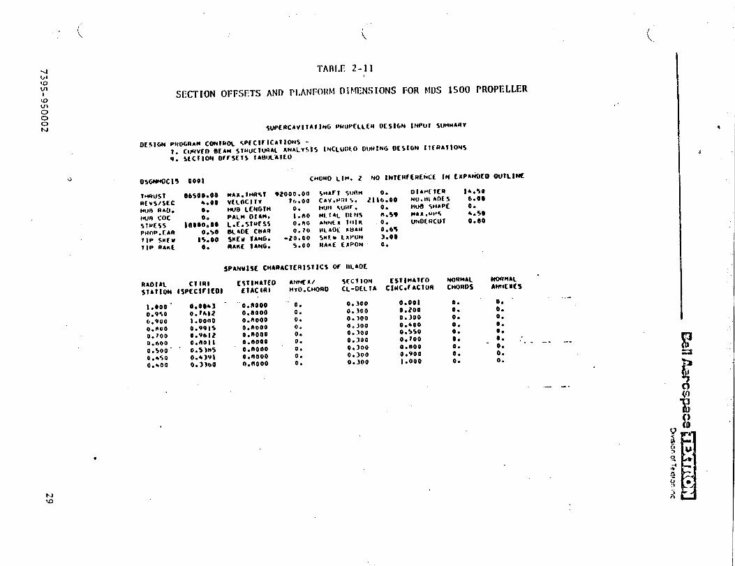
..
.
*
J’
.
eo
00
*Ow-
●***.
4*e
*0
0@
o0
$a
o●
.*.****O
aocoom
o
w
00
oe
oo
o0
0C
c.
eo
...*.*.*
Oae-oe;
m0-
09
*Q
a
It
i
iI
..**.**.
.0
00
0.0
00
0
,
.*,**.***
00
00
00
00
0
-00
00
00
00
Oeooeooeo
O.w
**a-s*o
......0
.●
OO
Om
Oo
Oo
-
00
00
00
0-0
Ooeooecoe
Fjm
n-l-,
nn
nn
.**.***.*
00
00
00
00
0
.*.**...*
00
00
00
00
0
u:
000000000
Ob-ooooo@o
oeec.eaaa
...0.....
-Oaeeoooo
‘d
9
7jQ
j.9jo
oo2
●
29
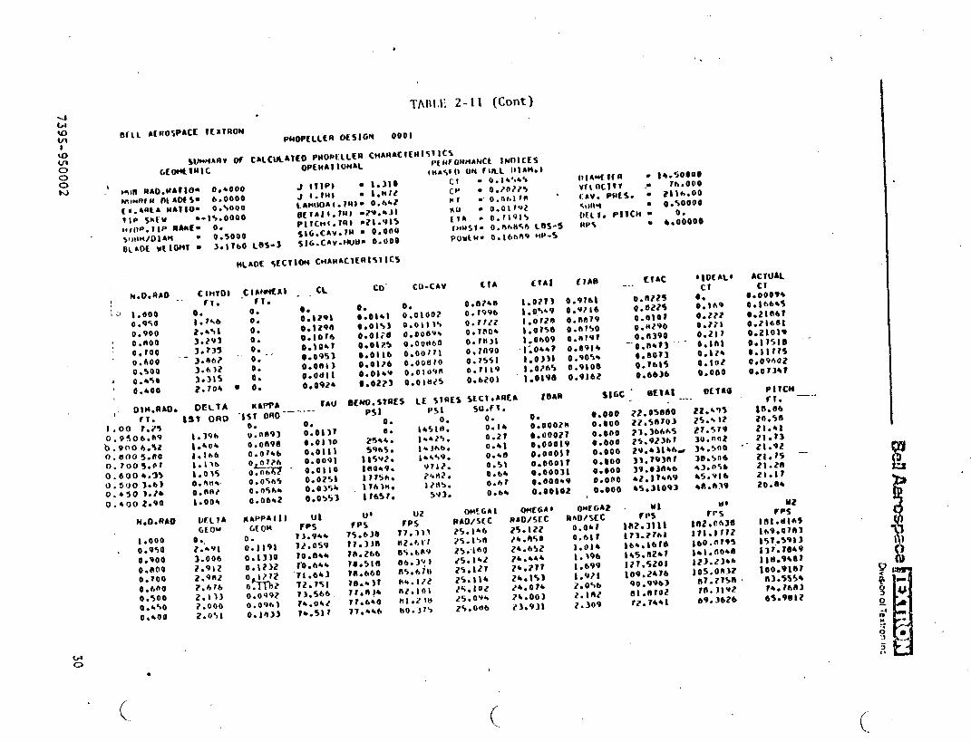
,
t
,
.
n-wcs.
m
*.
-l-lma4as-
,,,bl%
-*8*-------
N-0
00
00
00
●*..*.***
~.0
00
oo
oo
r,t
n.~
:‘
*b....****
●
*-00
00
00
0v
●
.0
00
00000
=000
●O
rO.0
;iee
,
●
o–
00000000C
.eccooclfieO
mb
uf-g
r).e.
..
..
..
..
-O
QO
O0500
3-----
...-
-
30739.S-9S0002
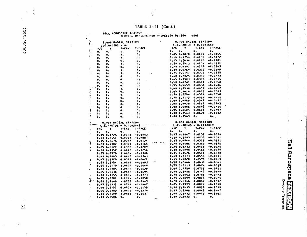
.,,.
..
,....
..
&●
“
!%!!Am
os-pace~
j’’’j””b
wo
nd
Te
xvo
nin
c
J
.
n
1Ii
1i
,.--’
U:L*****..*.
.*
******.**●
*x
lec
<e
cc
cc
ce
Coooccoooeo
00-
.:m.:Ou
a*.*...****
.*..*.***.
●*.
●m-
OO
OO
Oee.
e0
0*e
eo
oe
~*e
*~-
CWI
s:o?-
oa
●***.***.
●****.*.*
e...
0.
00
00
00
00
=0
00
00
00
00
00
00
2‘.a
u%
..*...*...
..
..
..
..
..
..
Wo
oo
oq
ow
ea
ne
~*--***~
*--
.:..
..
.,? --A-*-.
-.
.--,.-
---
-’___
---
.-A---:--
...
+.2..-.
.---”:
..
....
..
..-..;-
.-..-
.-
‘4
7395-95000231
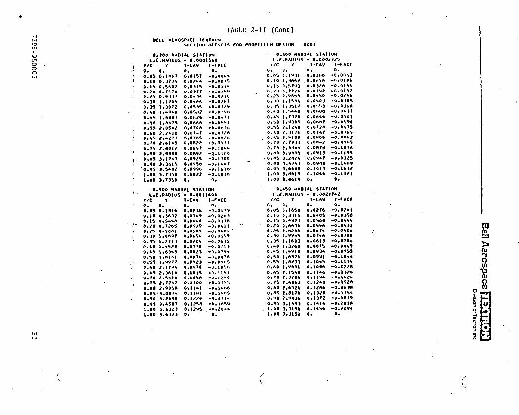
●
0.00td
Gtt.J
.
“1.1
./
,
i
I
iI
1
I
TA[J[JE2-II (Cent)
0.700 R401AL SJAJlOwL.t.ffADIuS ● 0.0001S60
v/c v V-CAV l-fACto. 0. 0. 0.0.0$ O.llm? 0.01%? -0.00*4O*IO 0.3?J5 0.0?6* -0.00?S0.150.56020.031%-0.0114O*2O 0.74?0 0.03?? -0’OIS’J0.2% O.*J)T 0.04)4 -0.07100.30 1.120% 0.0+66 -tJ.o/hr0.35 I.lorz O.O+J$ -0.0 )2’?0.40 1.4940 O.O\At/ -0.0 1~110.+s i*clnlJl O.OmZb -0.06710.%0 t.tt67s 0.0b68 -0.0ss 10.%5 2.056/ 0.0708 -o*oh]*0.60 2.?*IO O.ovbl -AJ.07/ft
O.*% Z.b?l? 0.0785 -o.oH7h0.?0 Z.bl*’j O.OR?? -0.OVJI0.7s 2.0012 o.oAt57 -o.lo~~0.00 2.9880 O.orw? -0.1166O.B% 3.ir*7 0.092s -0.13000.90 3.3615 0.09s6 -o.1*4~0.95 3.5*t12 0.0990 -0.iblb
).OO 307330 0.1O22 -0.18JQ1.00 3.~150 0. n.
0.500RAOIAL SIATIONL.CORAOIUS ● 0.001140@J
v/c v 7-CAV l-fACt0. 0. 0. n.0:05 OilslbO.io 0.163/0.1% 0.54+6
.’-” O.ZO 0.7265
O.?t 0.9061
0.30 1.on9r
0.15 1.2711
0.40 i.45?90.45 1.61+s
0.s0 t.nlfll‘, 0.s5 1.997?
O.*O 2.]1’?+
Ohs ?.lhlo
0.?0 2.5426
0.7s 2.7242
O.no 2.*OM
o.m%”3.oft7*
0.90 3.2t190
0.9% 3.A507
).00 3*63’f)
I*OO 3.6323
0;0?360.0M9O.0**00.0%J9Ooowva0.06540.0?14o.07ro
0.06?3
0.0R7*O.ov?l
0.0970
0.101sO.lo>n
0.1100
0.1161
O.IIHI
0.1??0
0.1256
0.1295 .
0.
-0.0179-0.0?63-0.031FI-0.0411-0.04H4-0.0ss’4-0.06 1s-o.or\)
-0.07WJ
-o.oi77n
-0.0965
-0. ln%h-0.11%1-0.1?%0-0.1 )<>-0.1666
-o. 1%95
-ft.t714
-(t. 1859-n.zobbo.
0.600 FJAOIAL StAIItJM
L.C.AVAI)IUS . 0.000/325?/c v 1 -CAV 7-tACt
o. 0. 0. 0.
0.05 o.)QI] 0.0t6b -0.0061
0.10 o.JMd ,0.0/’86 -nolo)O.is 0.5793 o.OJ/tJ -0.0!4%0./0 0.??)+ 0.01’12 -0.019ZO.ts o.fJti55 O.o+!to -0.04?460.30 1.15Rtl O.O>OJ -0.0 )050.3%” 10J\\7 0.0%%3 -0.0.1660.60 1*%446 O.ohoo -tt.u*]?0.6s b.?lrlt o.otb4* -U.o’itt0.50 1.9309 O.otdb? -0.0”)900.+s 2.1<40 0.01?0 -0.0675O.tlo 2.JtIl O.O~b? -0.0 rh%0.65 2.%102 0.0ft05 -0.0nb20.)0 2.7033 o.on4t -0.09650.1s 2.fiv6* O.on?o -O.1OTAO.no .).ltmw 0.0913 -0.tl$s
.o.~-i 3./tJz6 0.094T -0.! 3250.90 >.41s7 o.owo -o. 14tD90.95 3.6enn 0.1013 -0.1632I.no 3.n619 0.1044 -0.11211.00 3.L161V O. O*
0.4S0 MAOIAL S1AI1ON
L.E.JIAfJIUS = 0.0020?42v/c 1 7-CAV l-fACt
o. 0. 0. 0.0.0S 0,1650 0.02?6 -0.O?SI
0.10 0.331s 0.0405 -0.03%00.1s 0.49?3 O.o%oa -0.06*40.20 0.6630 0.0s96 -000s310.25 0.IWM3 0.06?6 -0.06160.30 0.99*S 0.0?66 -0.0?00
0.1s 1.1603 o.ofJ13 -O*O?M0.40 i.3t!b0 0.0s15 -o .ofth90.65 1.*U16 0.0~J4 -0.U9SJ0.S0 8.b57b 0.0991 -0.10440.=9s t.tM33 0.10*5 -.0.1134O*AO 1.Qlt91 0.1096 -o* t?za
0.6% 2.1540 0.l14b -0.! I?*0.?0 2.J70b 0.lt94 -o*l*z*0.?s z.wm~ o.tzto -o. I%znO.RO 2.6521 o.izn6 -0.lhln0.s% 2001?!S o.iJ29 -0.1?540.90 20W36 0.IJ12 -O011J?90.9s 3.1493 0.1414 -0.?olm
, I.otl 3.31SL 0.14S* -o.i?1911.00 J.J151 O. o*
*
(. ( (
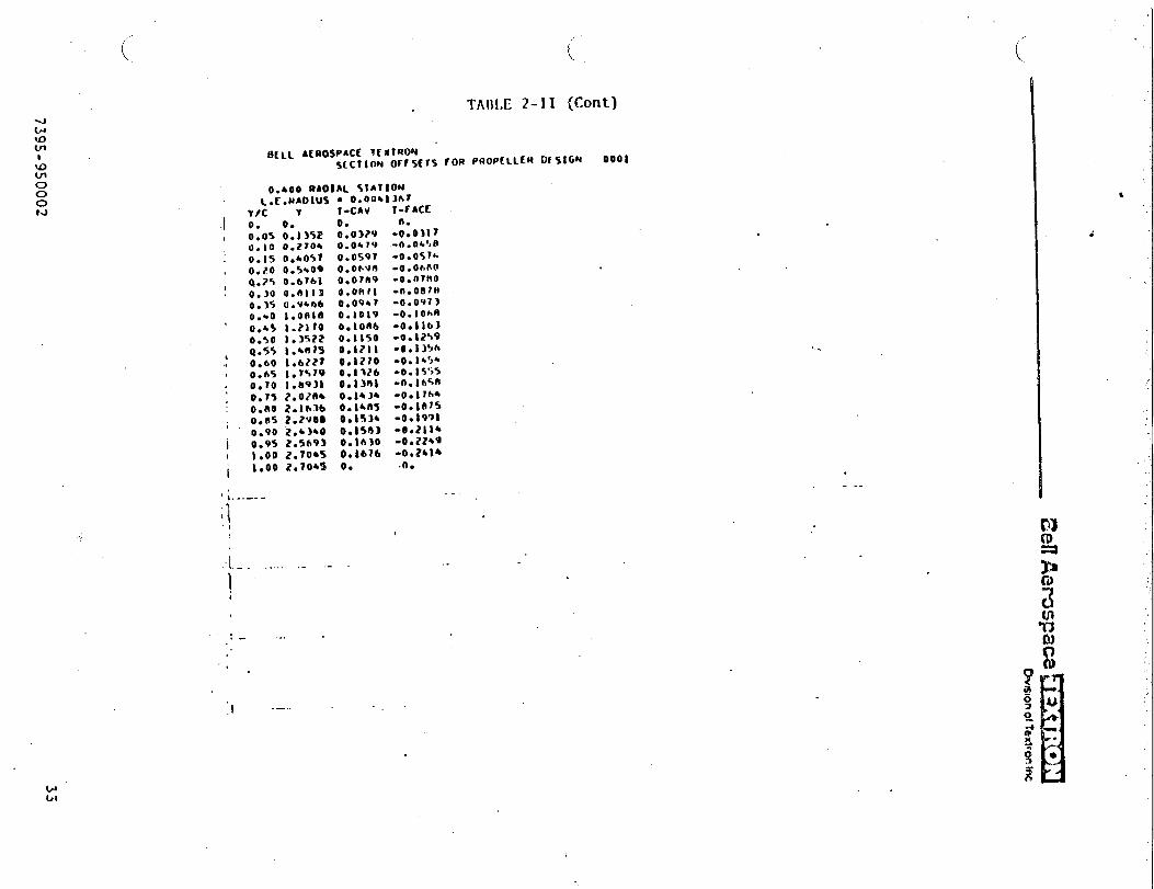
-.
c8A
000
.,
..
...----
-?----
...i
c--.--’—
-----.
..
.-...-
7395-950002

—.
...-.z<‘+
000
1
m
...—.
t
II
Ii,.\
II
,,I
“’-.-”
..
.
,
.
1.,
!
1I
i
1I
I!
II,
..—.
I__
..-A
-.-..
.-—
-..
..
‘4’
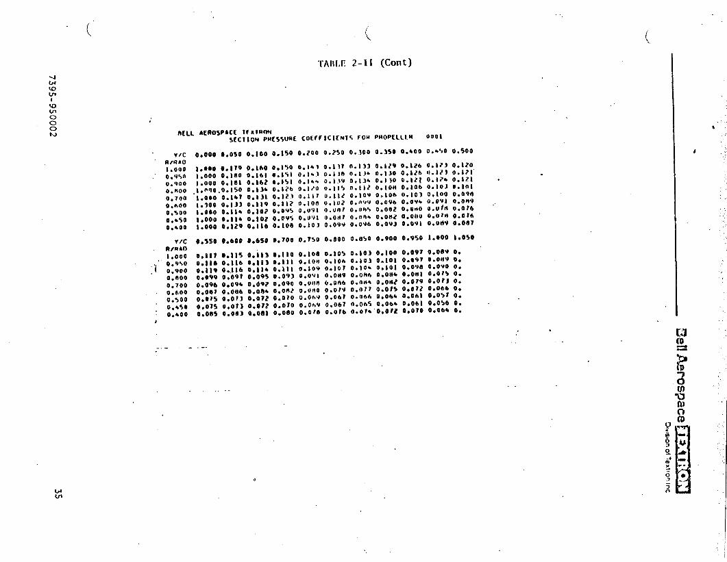
.
!zmIm
lE
3eIlAero
space,
n“wc8
xo
O“---e*Qe
-A
#rsrscexc-.e
----00000●
.*******
00
00
OeD
oO
4e
-41
-*0s
-%’%JNOO>
2=
*&
----oaoo
●*....**
●
OO
OO
OO
oO
-
m*8
n4
s>r8
Qm
-im-o>
.rc?----.-ccc
0●
....*.*
●
=Oacooooo
-e>e
’w%
--?P
--,--aaC*
---.-->
00
...*....
.oeeoooooo
..
..
..s0
’:0000000
O-w
*-e
%&a
a4a-n-0e-
-------
--
●**..*.**
000000000e
O-0-_~
4*b
mm
LJ!4-1--w
---------
..***.*.*
000000000
00
00
00
00
0m
oo
eo
oe
oo
Ooeceeooo
.***...**
---------
.-.
.
.********
00
00
00
00
0
*-Q
-*.%--O
*e>=-l-4
*-0
00
00
00
00
●********
Ooooeoeae
@--*
’%**8w
eoo%s=
-da----000000.
..******oooeooooo
*=7-co>>-
0002==&
c*--..
eaaoo
o.*
***...*000000000
O--n
o.%ooo
---*es*-a
--ao
oo
ae
o,
.0...0
..●
00
00
00
00
0
@&
a-a
*--m---ees--e---.0
00
00
0.*
**.**.*-0
00
00
0--
f-a*v
a-m
**-.--@
ee
.#-*
---00
00
00
.*..*.***
i000000000
IV
coeooee
o-o
\a0
80
00
00
1A
0●
aO
e*e
-e*8
4N
********●
=-0
00
00
00
0I
.—.
..=.
;,..
4
7395-9S0002
3s

●✎
✎✎
☛☛
☛☛
✎O
eo
oo
oo
oe
00e
-ucs
’4’
!i!iI
.:.
....-.zs
000:‘4a.
..
I.
1,
!II
U=e
oo
eo
oo
oe
\*eirO
OO
OO
@0
ma
Ov.YG
*Gk-,4**
%*.=****
=-00000000
.
t
36‘739S-950002

“.-J
e00
0.0c.
mmo
ee.1
o..●
.
“d1111
II
.A...-~<+
un
-w
J-
ItIl1111
‘.-./
37
739:-9S0002
●
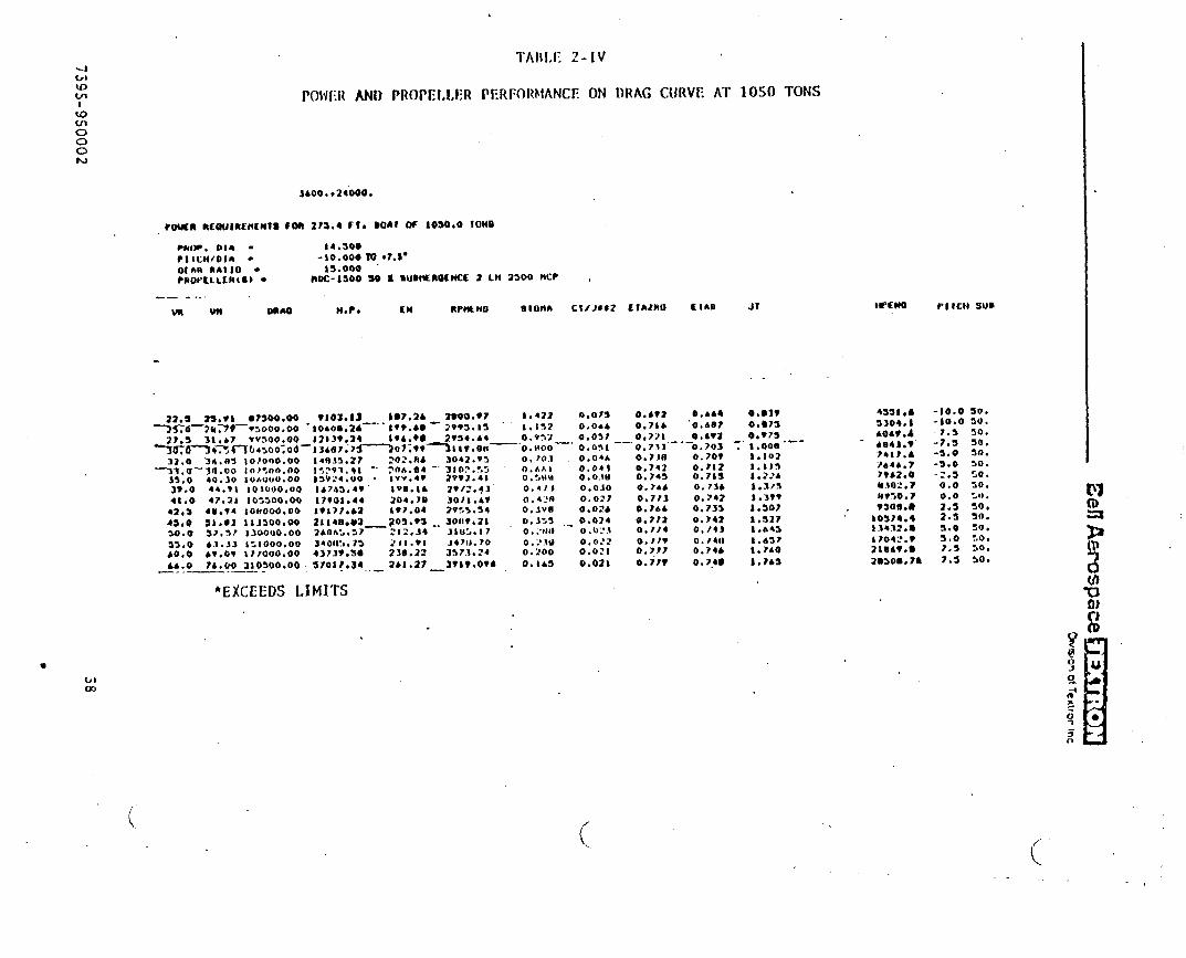
,
4bluu-!I
TAlil,E2-IV
POWER AND PROPEI,l,I;R PERFORktANCE ON DRAG CURVE AT 10S0 TONS404/1o00w
3AO0. ,24000.
PMIP. DIA - 14.500
PIlcM/oln - -io.000m +7. s’
Othn nAllo- 15.000‘?R07’ELLER(S)- 10X-1300 SO 1 ●U-_nOIMCK 2 Lt4 2300 MC? ,
blw
-— -.. .UKw Oaw $4.?. CM R?44Lno 81014A CIiJ842 EIAIRO Elmo Jr
J?*S 2S**1 ●?s00.00 9103.11 IS7,2A 2400.s7 S,422 0,915 o.bt2 0.464YST6-7413V*5000.00 ‘[email protected]”-l*T. &~-;; ;~:;~ 1*15? O.ohb o.?8& -O,m?
27.!l 31,67 VV300.00 12$39T24-30-W-34734764> OO;06—
1s6, ?0 0. VT12 0.037 o,7’Jh 0.4?113 Ae?. zmo7; ?*-ltv.8n —-0. HOO—’ O,o!)l --’0. 733” ---0.703
32.0 3A. B!4 Io?ono. oo i4f4J5*27 202.7!4 3042.V3 O,)** o.04h 0.730 0.709
T3W.:—Y4.00 10?”,00.00 1?,?91.41 ‘. ?OA. (f4 “ ;;;;:;; O.hht e,041 0.741 0,71240,30 I06WN.00 b3v24.4W . LYV.4? O,:,tia O.o.!ll 0.743 0,71s
3*. O 44.91 Iolooo. oo tA7’4%,4v IVII.1* zv/?. +3 o.4t J 0.0.10 0. Idb O.?m
+i. o 47.21 10:300.00 17?01.44 20+. 70 JoIt.&* 0,420 0.02? o,7t3 O. ?4243,3 ●u.v4 Iollooo. oo l*t77. b2 I*?.04 2?%> .34 0.3V13 o.02& 0.7*4 0.7334s,0 S1 .92 111300.00 2i140. W_205. *S . . 39~i?*21 0.1?3 ,.- 0.624 0,??2 0,?42So. o 3?.5? 1300 U0.00 2bnf.>.37 212. .I4 31 U3.17 0. .,/111 0.!):!.} 0.7?4 0,/43
33.0 63.33 I:looo. oo 54011 !,. r> 211. VI J4711.?O 0. :’.IU 0.0:2 O,)?v 0./6(1
&o. o &?. ov 17rooo. oo 43739.s9 238.22 337.3.24 0.200 0.0?1 0.777 0.74664.0 74.00 210300.00 -5?oir.34 2bi. il? _avtv*ov* 0.IA5 o.02t 0.7M O. 1.49—.. — .—— - ..—
●EXCEEDS LIMITS
(’.
0.03s0.673O.*75
-.. t.ooa “--
I.1021.$I!41,22A
Wwto rltclt sum
4s31.4!3304.i&o&**4
- 4e41. v”?41?.4?4.4a.v?962.0e.til:. vMvso. ?T30m. n
to3?4.4SY432.8
iJ04?. v
2104T. O
28s08.76
-:0.0 50.-10.0 50.
7.s 30.-7.3 50.-3.0 w.-3.0 30.-2,5 50.
0.0 so.0.0 :1).2.s 50,2.s 50.
3.0 so.S$o :0.?.3 30.
7.s 30.
(

<J(.8Q4JII
GL/lo00t.)
\<
TAI)I.E 2-V
POWER AND PRO1’ELLER PERFORhtAt~CEON PRAG CIJRVE W1”UI ~lf:sl:l,POl~ER, ~FF-CuSlllfjN
-. ....- ..—...-.- —-- -------- .--. —. .—-—
CIAO Jl K-tn, - PIICH W3
0.331 ●,4M 4A., -12.3 100.
1,s ● .44 JW)OO,OO:::: tl*!Jl 24300,00
14.3? 33500.00-Ts.m-tzYnlmo;oo
—bvooo. voYo+%:z Toooo ●OO
22.s 23.*1 I150Q0.002*. O ‘27.44 IY4000.00
b ?a. o”’”Jo*m !J*-*OQ
S24. S0 42*A5 720.43111*.2A ● 1.24 934.24:WA.13 TO*W _li311*22
—mo2:?*- 110,53 i27i.n9-- Sqot.m “- 114.14 _tJ12. ?o ‘- voa9. b4—-l lb.&t 134* .04lJo?t*23 131.A4 l!t14*0391AM3.66 t41.oo ib30.71917332*ia i44*7? ““8444*R4$
● EXCEEDS LIMITS
t2.7?b?.STU4.404
-J, !?v“2.390
1.?9?
#.422
i .270
1*A52
-.0.A14 o.di?’
O.I IA o.4eb o.4sm 0.-140.107 0.700 o.4t2 0.9400,0?9 o.71a 0.401 o*M12
—0,07V—0;4W —0.4?1 —“o. v4a -
C.a?a b.mh 0.4JV l*07a :O.o?a ‘0.433—0.400—::;::-’””0.0?? 0.A32 0.40?0,102 C?. A28 0.403 1.1020,074 o.43b 0.480 1.204
. .“’ *o&ea
242,4339.4tl,.1
---B73t*i-
“ “ 2*00**4344. s*3*!I.U● l*2.W6*74.1*
-1s,0-10.0-10.0-io. o- 7.3- 2.3b 2.sb 2.3
4 2.!24 2.s
too.
100.100*
too.100.too.100100:00
100
wu)
4
.,,

,.,“.”,’, .. ’..-, .:..,’ ., ..’.. ., ,”... ,..
.J’
‘w’
. . .
~~~TIox 3
COSCLWIOSS
..
40739S-9S0002
._/
h efficient 14.S-foot diameter pzopellcr has been dcsiwd for the!SS 1500-ton ship.
Altcrnztives Of one gas turbinz per,prcpellet, or cne gas turbzne and one
.
~~e~e~ ~ach, Fiz\*e significant gdvant~ges, dependent upon the use of the
A denonstratcr SES with only gas tusbines }:ould ~eztly Siqlify
vessel.the propulsion machinery. Hoxever, the range at off-cushion speeds would
be Z.UCY.greater with diesel power and COOOG reduction gears.
3.1 Reccr.ne~2ations
.
Contin~~ethe p=opeller design effort to define the propeller hub an?inte~$aces between the propeller and the hull. The d:s~w must satzsfybcth perforzzzce and structural considerations.
}!akethe propcsed inprovenents in the SCRP co=puter program, so that the
experience ~a.ir,edin the present project will be readily available for the
design of ne~ strper=>’itatingpropellers.
_.’.-
.-
.
4173CII-9S()()02

. PRIOR REPORTS
“-J
42
7j9S-950002

. . . . ,. ... “., ... ,:.....’,.......’. . .. . . . . . ‘“.
.J
APPENDIX I
SULZER-ESCHER WYSS REPORT
.-/’ .

,’: . .. . .
. —_— .--- —-- -—.—— —-- - -— ---— -—— —— —--- ---- --- --- ----.--.—- - —---- ---- -. - -- .-..---. .— -—. ,---— — ———— —---— --..—- .--—-— .— ---- . . . ....-.-— .—--- __, -. .._. __ .
- -— ——— ——--—.-— -- ....— . ———.-— —---— .- —- -. --—- -. .-.. .— ---- ------- . ..-- —--— —-— —-- —- ---— —..—— —- —-— —- —-— —.--—.. ----- ..--—. -._.. ______ . .--— -—-. — —.—— .-— --- ----- .-. —--— --.-. . .. .... . . . . . . --
.-0”
—.—
.— - ——-—- -- —- -— —-— --—-
—— —-
. .
‘J
SURFACE EFFECT SHIP
(SES) 1500
Enclosures to Report No.:
170/00/0010-02
PROPELLER DESIGN
.-/
.:
——-— -—-— --- .-—— —-. . -. -— ——-- —--— .—--- —-— —.— —— —-— ----.—-— ..— ——.- -. .- -—— --- —
.—.—-. — -- —-. —--- ——-——— —— -- .— --- -
..- —-—.— —- —-- -..-.—
.— _—. —----- .- ——~ —---——--— .-—-.—— ~——— ————— ———.-——---—- —— —-.—
~
A— —. —.-. — .-—
.-.—-. . .— —.————- —— —— —— —
:’..,j-!w)!w)t-) }.[!- ~:.lf.dc (,? 2:I(KI r.+0.:dfGI.(JICI-’.,:;1(-:01.-+.ll() A ; ?’:: “--’.-.. . -. -— —--—---- ----- —-----... . ..-.-.--—.—----------------- ---- -----------. ........_.. . .. .----

,. . . ....,, ,, ,: .... . ... .... .. . ,., ., . . . . . ,,, ,.. . . ..’ ”’””’ ““. .. . .. . ...”.”’. ...~.: “., .’ .’.
* 46
SULZER-ESCH; R WYSS Gesellschaft mit beschrankter Ha ftung RAVE NSSURG
4 SNJLZER ESCHER WiJYSS
J. , I 1’I t. I’c)cj IJ(: “1, ,i C)l”l!.
. . . . . . . . . . . . ---------- . .
.
----- .. . .. . ..--------- -----
u ~, se~ectl~rl Of F’r~F+211.c+r Iliarrleter----- ----- ------------- ..----------- -----.,

SULZER-ESCHER WYSS Gesellschaft mit beschrankter Ha~tung RAVE NSBURG
:,.,..1.,, , i P, ,!.
we,,,.,,,, . ,4,,,..,,.*$>*.,.,*,-.,.,,,!,.,,.. ,,.,cWL2X3?!ESCHER LJ5?JW5~: 1....!.,.s8 ~,$,’$’1..
.
“w’
.
●
✍✎

.-/
“d
{ 1 ! I ____:’ -—+-l . ~
, I !.: ~ !. !i. . . . . . L+... ---: ---- ‘ - -“: ‘—
*--.;— .— -
;. . L...
. . . . . ---. : ..; -.,--: -—- -: ----: I I ?
,
r-:- ~.---.-.l--’;...;.’
.., -—-“” ;.;
~: ~’ ii i........ ,“. --- ‘L-- _... ~.- -: ----- . . . . . -------- !---- y-----
. . . +.-L *..-.-..-:....:._;_”-.--”:-- .: , :, [.- ++.+:..
ii~. 1: .... .-~.-. .------ ~ il-,
:. 1.:”. :“
;“, :.,:. . -- ,.
_- ::.
:.i’:, ; --- : ~ : i, ; +.+.+-”-k -—v--
. . .:: L
,-+----- - — -: .”--- - ,------ -- .; :””: :,:; . . ,.”
—— ,
I i.: A--+-&--:.: i; .!. ;. :,.; ~.:~.
i _L-_ .1. ... ...---- .-!.—---&--i ~ ~ I .:.: ~;.~ ~kYY- ~ai~i2&FrifCJNFN.0L75Q-Q ; ~ ‘ ~
1.__ .-.-.+. - -----:: ;“:. ;’~
,, :“: -- .-L --—y——---.,. . ----;------.—--: ---- -~—. ...-.’
_fi:%.7ub122:-l;&e-J-~L$=~~f2 : ~ ; ..-~” ;;’ ;j :I---- !-( I ~ ;~--y
LT,---~— ““--+----- “.:+-r : t—.- —--
--—”— “ ?.S.wfisou. smd;! 57EEL. VAKWmm ...._—— ‘~f_?.8W.LT—-45(X) ... ...... .. ~------
-220,j ; / ....\..... y ~...
-------- .+= Q.-—-—----- --------,.. .— -----
,--
——-,,.
_-——. .
—gf-J&
-M--- -.— ..-
:---- -
-+f3e–-..
,— ...-..}. . . ..
-- -
__ -.. .d
g.- -
------
—--- —-
....”. .-
---- 4G{
-----
. . ......-
_. -----
—.
.
.-
-.
.-. ..
-.. .
.. . . ----
-.. . .- .- ..-.
. ..- ------
—. —., -i -. -.. .
—--- .- ---- --- -----
,.-.
.-
-.
----- ---- / ~ -- ~~. ?- ““”“’”. . . . . . . . . . . . . . . . ““,
/
L-- QN-, CUSMC------ --—---— ---------- -------
1----’ _-150t2 i~ .-... ...- -------
...’...:Ss 6----- ...-.-_r. /--- /.__---.:-..
OFF CU5tlIOH ~. _._. ..... ........ .-!..__./... .. ------------- .-.-.‘lf$OO L~
.. .. . . . -, --:------:.”-. . .----- ,____ ____ -. .=--— ..-—
-_. .—------ ---- --- :’:.. :..- ... . .
:. .-..-:..-.— .-—+.-—-. --—--— —.-. f)~A6 VERSUS.; WfB~---
--.. .. . ----------.. --—..- —-—-- _- ——-u-- —- p%-=~z +Rez.c+l .:
------- -. ~-....- i ..{.. ,_j.. +.. j.. .; -.~ .:. +-.. ‘..:.-.,!_
0 -- +o --- ti ..” i). ..:.. - (0... ~-.. @ +’+.- .~-.:-~p :- ~-”:------------ .—--.-—-
hJ -*
1
I—

_- —- .
. .●
,’ , I—— I -~
,.1 .- -I 4
-. I.: I i.: !. I
, ; _,; . _~. :.. .,Ii . . .._-- L.-—.-. . . . . . . . . . --.’ . . . ----- -: —-—.- ,. ..-..’ ——
-. 4--— .. --- - r---. . . . . . . . ..-
:.! . i’. i i ! j _~ I,. .- -I
~ ; -. [__..:+_:_
~.~.i ~:’++-- ..-..:.. --- ; -, --{-- ‘ ._.J - ...:----- .–--:..- .-.. +.+.-.--; -- .-. ;----- :.-....-..;.- -._!-_;..-}..;. >’
.i 1 “:..’.;
i’t”::’
!, - c----- .l_ . . . . . . . . . . ..-.--> ..--.-. -!-.. .--... -----
,
;,1;i -... .-~--_ .;_..;_ ;_-L___~-.~._-~ --- \
_ -: ----:~.
-- —-
I__. L__---------.L--:-.--i--~l’”~,.~+:+ .-:..; ;::3q-..-—-..-1.
Is. . . . . -— .-.
. . . . -
.-
-“>––- ~ “o-------.--&_.-._––..8 .......
=l_____—-..-Q.-.......
..-.y -----
._i5..-----
.’1 ,:’. i“!,-
i’ i:!+---+ [ ~------ ..-———
7
-.,----”j---- --”-iq5Qo--
---:$: “-“- “._3; - .;------ :-----.;...=+- :----–; -y-----.—,.+.- -- ..-.2 -9~ocl 6: !
— --- .——- ---—3 Llrg
j: ! i ; JJ___:. q5g-o- . .... ,-—– ------.;. ... . ---- — -.. .—--- -------- ,.h dos k ON
-J-:’!: !”; ::!i’
.—-—.5 %00 ON u“ i i i ! ‘ ~ :_;-_&;-r -- y-.-—..—— ----~
l“..!,;;- .L ----
::. i::.. . ,_._~
i1
::: :!.‘ .+:.: ~ “- “ i_.+_’_.. .._.. _.. _-. .._. --...- —__.. -..--: - . ..-. --—:—
.— --- —,. . . . . . ,. ._. .; .-. . ::;,
;“::’ . . . :.. ” ‘;,~”:
----- —---.— —.-—,. ,. :.
;. ._ :.- -. ._:----- =-—.—- . —-—..-_ L-.;---- - - -. . . ..- . . . . . . . ---------
----- -.. :— -- -. ‘. ..;
-- —— -- —-— .
. -- .- -—- -—-— !,;
R
32. - @
‘.:x ~ ~ “ ~~
:.- .-.: -- ._....-.+ .-—..\-
-.—.... .....- ... - ,---- , ... ....
\
. -_._. —-——-—-—--— — --—-—.----- ...——--------—--/-”- ----- .-. . . .
L
-.—-------- --------------- ------ —-.——-------.. .— . ..-.-,.. - .- .,-----..-. . . ...---- . .. .
___ _--- —-,-—.-....—-~— - ------- ._ ....- ..-——--—. ..-..
.-. . ----wt-~/~------’--’-’---~’i--::--. . . \ ~~ y -. . ; ,..-. . . .
““’-\/ .-:~:.-,—-——-... .-............... :~-.------“-”–--”” -- -’: .,. . ;._:_-_..-“-; --
\“” ““-” ‘“--:””’-”;’_-’ : ‘–-.. — _-..-—— ---——-—.-——-.--. .—---— .- —.——-\ ., ,. . .. . ,:.. ..- :_- ._. .:.--’ ...;. .-. .
\ ,-, -...-.. ... ..... ..... . .... .-. —----.——-—---- .:—-........ -------- ---- —--- \ ,.,l.- ~~ \: Y\ “ “’:””-- ‘--””!- “-: - ~--------d
-11--. -.-—--.— : : ; -—- ––--.—------- .—. -..— -. —.- .----i . ._ -; .. . . L+...:..- .-:..
.“ .- -: . ..-. . .
_. ----- ------- -. -—.. -----
‘-. . . . . . . . . .:“” I1
----------. —----------;----.:----... ...------’------.-~....” . .
------- -——- . . . ..- . . . -- ----- .-— —’—— -“
.- —- . . .._, -- .
-. . . . . .
:“. :.. ‘Y’1..:.“.. - +) ~,“ . . . :-- ”-:
,,
_— -- —--— .-. .------- ---- :--- -- .-— ---. — .-
- s ?<5~-lZz-7ia-;::”_.....-..:, , 1
—, t 1
1 I 1—— 1 ,
0 ’10 ‘ ;----”+0 ‘-” -1-“ m--- i-–: 6$+”””-%---”Qy” ;.-.. 3~. .-i
I
.____— ..- —.-hg -ma
b.
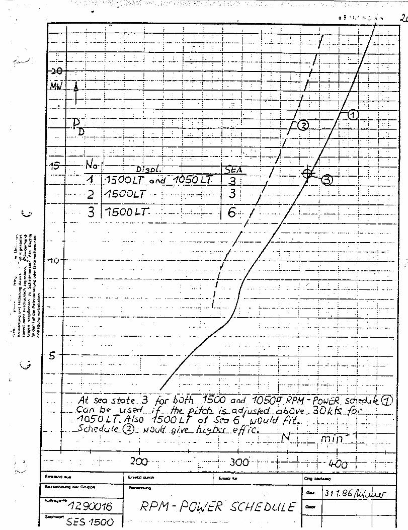
u’
!.<
... #
-d
.
—
--
?3.....—.
%. !.
.:
1—.. ... ;..__;..l....l.___.~..._.~.:...;....!..j..:f--j/+--:----.;----._...-.-.:-.....-.i._.....
,.’ : .: t-.. .
i .: .:.: :,, ; i-:--i- .“-l ----,
:: :::. :: + i J,.
-.-...:. ;__;. . :_~...: -+ .: : ~ ~ /j \ ‘;.:
—: — —---- .: . . . . .. .. . . . . . . .: .. ---- i - -. -<-—-. ..— . . ------- .. . _._:,“ . . ::
., :’ . . . i I i:,. . ) I.,. ..:, :.:::. . Iwjr;:’1---- .----: :.,
w A i----~ ~ -’-”~--+: “! “ ~ ~ ---VI-: : / ! -: !
, :.---- -: . -J ---_,____ -
!. .:’..
:.: :..,. :. I
-P.-.—-.,...-—-__..L......~- .-A+ --—— :“ ::’: .~....
i“. !
“-D’ ~ l: W.::”._..-. .. -—-. A.. -.--* -.. L -—7- . ..- . .._. .
1:.. I ‘:. ;:!. . .;
i’.::”~!:~: ij. i. l.:-::..—.-”:—..,. j.:___ .....—. ..—— ---___ .._..:._.
U
..:—-.i:.
=jf :*+-+.4 ““ : , ‘
“-””-”~.1500 LTs~n; dQ50 i-~
. . . .. ... ......—--- . ... - . .. -.-— ....—-- —-—
--
.-
.-
-. .
-.
—.
. .
---
---- P_Y23::L-’-”~---~’-2 pm -~........+....,’
—-—
. .. .
. ---
----- ..
.-
3 I7500 Lr ~.:-----~-.--=---I 6--:-/’-- - !--+---; --------+-.. ..- -----.-....._.__......
/’. :
}.._:___ ‘ : ___.-. . .. . ........ .... . . ..... .. -.&_..---,.-.,-,--,-,. ;--.-:----.,,
[....-. .... . .. .. .-..,.-.... .___... ..... ______—-— .——--.——-.—.-.–. -.– —------ ..._-. ..... _____ ‘ ~“;--:“
......:..-”.
//
= . . . . . . . . . -. -.-L —---- ---- . . . . . . . . . . :_. :::; ;’: .,.
. . . . . . . . . . . . . . .. . . . /. -.> “---;::.-“_.<___.L:_:i.::I .,
-.. —--- ____ ._
‘-”-—–-––-–-— ‘——’. ... ...‘ ;-‘“ : ‘“-“:’”---:–-” ‘ :-------.... ..------...... .. .....-...,___.-.--,--..
:::::;..-._. :-..___rIL——
------- . . . .....,_..- .,-:::———-.-.___----- .. . .- ... :-=--
:.;. . . . . . -. ---- . . . . . . . . . . . -: . . . -;. - -.-A. .- .-: .,. .. .
—------- ------ . . . . . . . . --. .-. — .. _A __ -— ___ . . . ___ ____ -.,
. . . . . . . . . . . . . . . . . . ---- .- ----- . ..”.. -..
-—. — .— --- ._ .—-. —;.:
. . . . , -. . . . ..- ..-. . . ---
---- - .-. ___
. . . . . . . . . . . . .-. . .. -. ..-. . . . . . . . . . . . . . . . .
—-- _. _:_. _
. . Af SKIStQ
.-Cciflbe. u.4050Lr
—. —---
.._$chedL.i~t@I tdC@. .~jE &y&f_.efll.Ci ~ i ~ i ~ ! ; ‘:.I. . :---- -. . . ..:-. ~-~ in ‘fi--:--- ... ... .-._*._-.-.:.-._..:..-_,. .-..:- ,--— ....:..-:-
!.1 ;: :::
t 1 , i1
1I
. ...--. z~. .; . ... . ......~...+.. 3@-. f...,_+_+ ___j-..:&+_ .+..
mwMJ8
-“qz g@,6
“- SFS “7500
1

_—. ... . . ,,, ,, ,. a,
‘u
\. . .. .... .. .i. ..- .: ---- :------- .:.... -—-- .- ----
—
1’!.1
. . . . . . --- ?_.. _; —-._+.- -..
____ .—-.— -.
—
i_. &—.-.-—+.———-—-—
.. .-. .. . ..-. 1 -... . . . . ----. -:--
—.
., ;_____ _&_. L....... I - .---1----- ~~.. -------
--_..—— ..:——,.-
1;Ncj—.--’
+--
““12
3f~ –
4
t
..— —
5-. 1-- -
1.
7500L~
./l. . .............. ~j;.;..,.-. -,-,_‘..-....:, ., . , .,..
0 ._——-—..__-—- L___.—---.—.-...-----Y() ~’ ~j-’ ‘-35 ‘. .’........ , ,...,....- ~.--:----:--:----:-----
/.------
- .---- ..-----...-.... . ... _____.———-0--- -—---v5U0 LT 6 - ‘---- ~“----=L=-L-------T--–---:-+----
---/;@--” --””---T--- , ~---/.--.—.fi~dO LT 3
/
.x’ :-. — -:----!.... .----oFF C- -.
[B
.- —-..-...—————
!
—~ +-------- .. ... . . . !,. ...,
In ‘.< .- . . ..----- .--. — --- -.:\
j.=..
- .& --_-.. —---- ___ -- -—... ---- . ..-— —-
,- . . . -. -—--—— -.
,
5- –... .. ___-—____..—.——-----—.:.. . . .!.- -------...1..’‘1--’”.... .-. :, .__ —-—.. ..
$-...----. ...... .. .. . . .... ..........-.. -{.---~. ..----——,.-----..-..- ---------------:
______.--.-.—-..--—...—--—-------:.—-..— —.-.-.. .
.—-..,. .-— ---- ---- ....’ ----
1
G-aw’ta-*
04I-—. 00? GIJorm
.-. ._:. —. -———— ---big **

& .a
n R ,.: .r r IT z . . . . . . . . . . . . . . . . . . . . . . ..
w
!-jt
-rq
{—.
~.= .
..
.*. .
..
..
.
c r,n x -i T ,,. . . + . .
I !
m“:
c f- N m,.
m
G IT r
.1 I~
.. ..
.-?
7 z,-
.s.
●
/-*
~. t=.
-i* 4*
..
..
..
..
..
..
..
..
..
..
..
..
..
..
..
..
..
..
..
-ix
P-i>
z-l
LZ
I.7’I
++7
?!-H
H
. . . . .
..
..
..
..
..
..
..
..
..
..
..
●✎
✎✎
✎✎
✎✌
✎☛
✎✎
-1 . ,.: r r
. . . ● ✎✎
ir~ xl
‘,
<“
-c m (n
f-q
~,
. . . - . ,
r - :- Fl
0 Fi
. . . . s
. . . . .
. . . . .. .
c-)
4D
VI
. . . . . . .
. . +~ ,.- .- ~ L
-;
. .m
..
..
* .!.0
. +●
—,.
.- = >“ z
-i
..
“..
..
E.,
+.
.<
..
~.
..
.
-q -4
..
. . ● ✎ ●
- ---:
.*.7
..
..
3.
..
-.*
.x
-: -. :.;
. —. ●
*.
4
-: :. . .- $
m > < m z U) m c :
-i
,.,.,
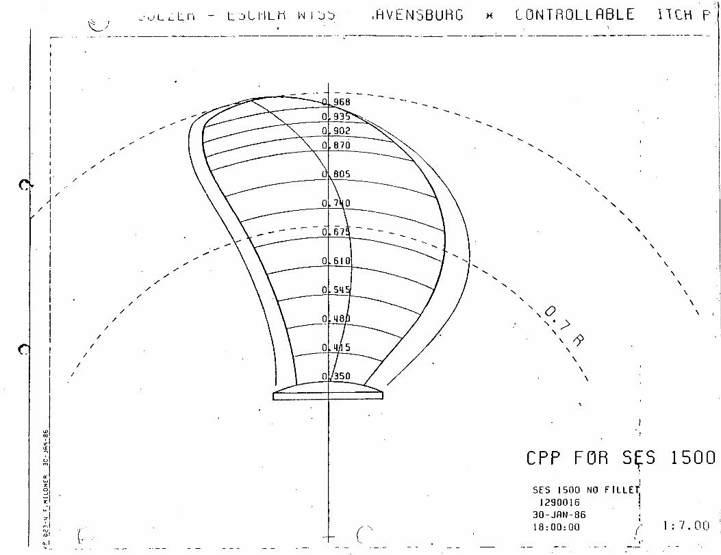
...
I..II1
-\I
./:./!
i1._._-
_
+.“’
r‘-//”
Q;,/
-..-
00inm
!●
✎
-i
Cz”
I
C3s’
I
Ll-00%
0o-1
o
\\\\
\\
\\
\\
\\
~,\
.-—
-.
—-.
-.—-
--_=__—
..-
tIIII,/’L.’
!IIII
\“\\
1\
1\\
I
\I
\\
\\
I
\1
\
\\
-—.—
——
—-
——
.—
-——
——
.-—
-—----
-:
98-htlr-oc
83N
071U”j
h-fz?d
)\
C\
b

APPENDIX J
STRUCTURAL DRAWINGS
..v_
...~.*L.-
●
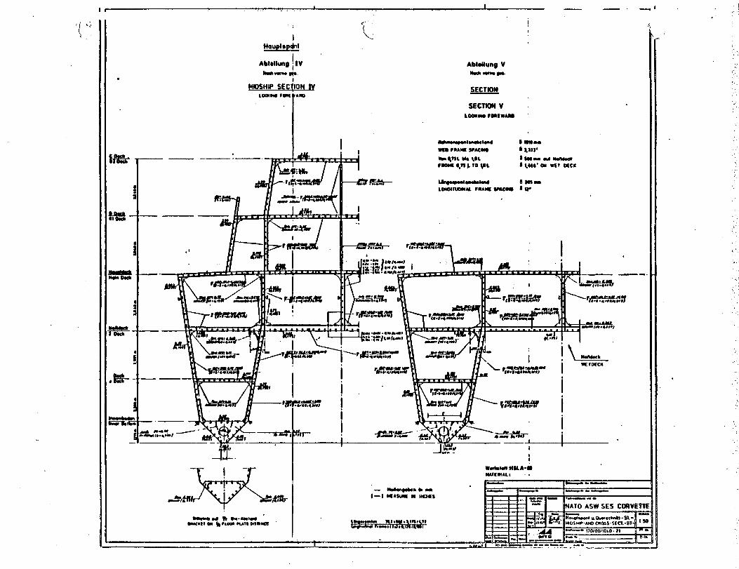
. .
.
1Houptspfkd
I . . .m
-— .—.
Abhlhtng VWwJIwump
SECTION
I
Whld WA-L)UIIMAL I ,
1=l—
.—- WOm*klM 1—. l—. —
(-l -AWJM M IKMS I1 1 y_. - .—. .E 1 t-- “ NATO ASW SES C(M3VE9TI1 n 1
9w@ua19w<lnai-s8.-
n
. ..’.
:.’
,.
..‘..
.
,.
,,

-
—-
IIi1J.
....
,...”’
;btII,I.
-----—
—.
——
.-
.-—l~
——-$——
-i----
._
—$
_*---
d---
,
:---*---+
----~T+--’--k--*
,-———
r●
+----*,: L
L-;--b
-:-’F*
.--—
-—
-------
—-<+*
_—--
—*--
●t
--——
-------
.-—
-—---~-—
-“++-”-+-+;-
—--
d+
+-+-+-+-U
●. ——
—-
+-—-__
+----
.~+-_,--*
-A-*
—-
—4
—--
-_--y-—
---
● .=--+-..
-+_-
—-
-:_-___-+
-----d
++-:—y+~
—--—
-i---”
“---
-1:_-:~
“<;--:--:--~.+__—
4--:
-,-pI
.—-—
-—-—
-—
*----
Xm
+–-W
-+
,-—
--
,----
*---—
.—-—
—*_—
—----
-
--—-
-.
——
—-
-—
----●----
-.--
-—--”
—---
*y~,
__-_!
--—-
●+_._
-+--
&
IIIIIiII
,,1I1I
II>
1
IIIII
.-
1 :1

—- -.. .-.-.-— . .------ - - -
.
I
I
I
-—.—
, G &I a.-I . E
--—’ — — — . —-- - —.—k ---
&
I
0-.%=..
-1 ---l-t: 1 I 1 1 1 1 I 1 . i 1 , , , ,, , , 1 1 1
Q —.&. - 1 u m m I n 1 r r F-1 —
II 11’ II
.1I
Otcn SWINGER ,I
* i 1 I . . m---------- :1 .. .— ---- . -* -.-< um—1-~ u~
—.- .
.
,s; i“\-.
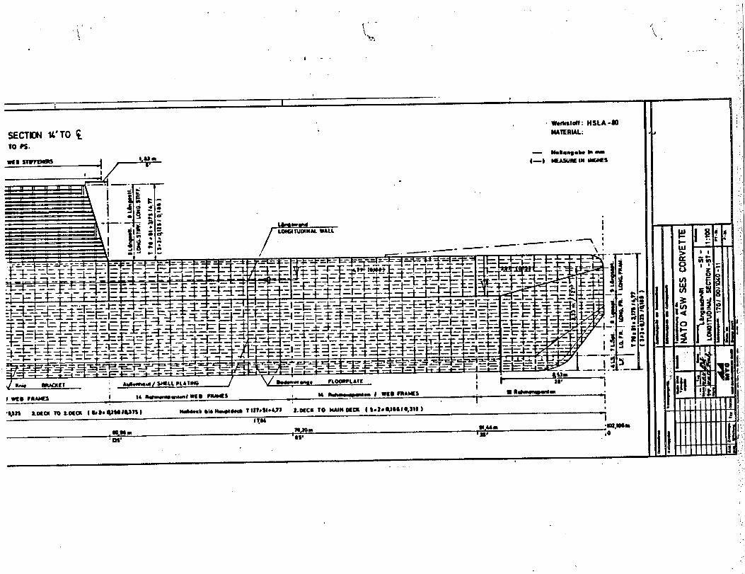
...
..............
...........
.:-.,
,..,..
,....;$.,
..
...
...
--——
-.
-....
-—-
-.4
.*.U
It-O
mloa
loLk~
I
.:4
0
ii
.
-.
[ :.
I1●a
.,.
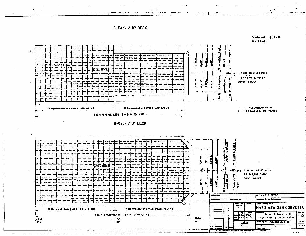
,.
( <::,.-.+. *,{
..1 --—. —---. .
. . . . ..r —. -.. 1 — .. -—-. —..
Wcrkdot! : IW.A-UOMAIERIAL ~
C-Qeck/ 02. DECK
0
fLONG I!. G lROER
—.—— —.- —— ....- ----t-.——-,
. .,,
— Motlangobonin mm:;.,
/ — ) MEASURE IN 6NCMES ‘.13Rahmmbdbm I ~0 PLAIE BEAMS
i “ “--”””— JIA Itdmwnbdbn lWEO PIA?E OEAMSr“I
‘-1 11?97C*,JSOI 9,$2s (9t3f o<~5010,115 )— J
bEM3eck / 01. DECK
,..,:,:..
— .. .— -. -—. . .---- —--— . .—— -. ...= .+/,\\
—— . ,. .,$:..
---1 I
I 111I ,.
.,
ls--B—l-–t-l---i -++-+-++-+ –+:-+ I I I I -: –1 ...
I-. .,
.’.,.
I*.”,NATO ASlk/ SES CORVETTE
. 0!. AND02. DECK-ST-t-b.-w ,y~j~(), ,~~o.lg ●1&
*.W,—- ,,,dle,..,,
#.w 1*....* --- .- . . . .. 9. A- * . .. . .
14 Rahmwbalken ! WES PLAIE WAU5 --4i] ilohmmbdhcn / WEB PLATE BEAMS-. —— . —— .-. -.— —
i- 1 12?.?* ●q3*om, $s* .( !:I*%?!O ! Q!?? J -— —— --- —. .—. .— g
,30.48 ,45.71 60 M
1)5’—. 4 —!-.—
185’ 1351
1. ---- —..-. -.— - ——_ .= --— —... —.: -— — — -———--
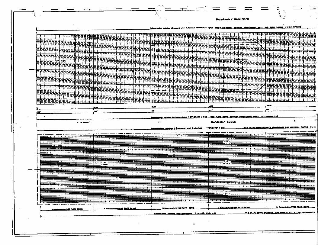
.
IIII7“‘-,:../
18’
uIIII.11,1 IIi’-.
,,,IIIIII.+II
.L.—.-d.
-—”*-–”–’–-–-J
i
I
..
.-—
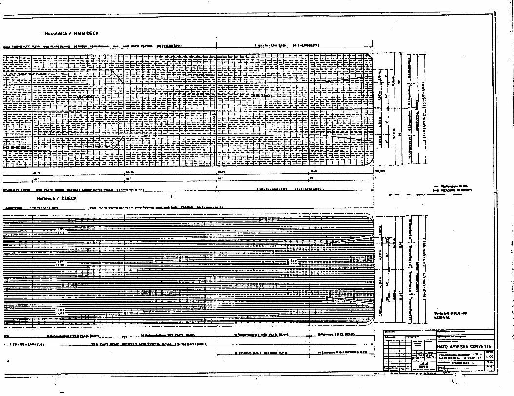
1 [
Ha@d@cbI/ MAIN DECK
#idMutt / 2WXU
- ~--t-l ~ m-s
—— -—
i“.,
l— .—
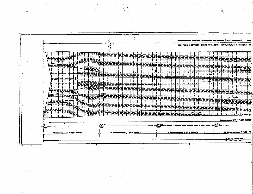
-,,-
,...
“1-7+%
.
.—
------.
..
..L
——
.--
.—-.
--
..... J,.p
-
A..-..-—
.-.

,..
...
..—
...
.-●
~-1-I11+-”-1-’
‘-:
i:0!...! .-.!I,Iis~k+—
.*IiIiiiijatiiIII-.Iii-U:sT
-1I
!.
...
“\;
...
.
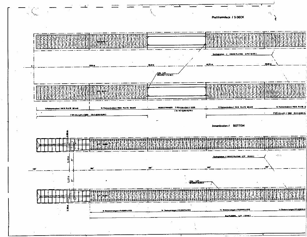
.—
/1. .
.J—. “-L— -=-’ “—- —“-”
I“— “— —’ -—. .— -
/
‘{‘i., “(
P!aWarmdwk / 3. OECK‘1
I /,, \
-i —-—”–-—-—-—-—an ,Wa- ------ 4ss q. \—.— .—. — .— .—. — .—. — .—. —/’—-—“
-—.—.— .—. —
I.,
‘,‘\
.—. — .—. —.— -—. —.— .— .— .—
—,. —.— .—. —. —-—.
-M19mn # -s mA!89 4n mu b (,,.,,,
‘\
w --14- -“ Bw_.— .—. — . . . —-— -—-—- —. —- —- —+-—-— —-—-—-— -~- —-—-—-—
.
.—. —
—. _. J!!J+._.—.—
‘\—-—----—_— .—. —-—
.
I ..—

I[m
lvnm
,1,cl4
0 ~-----!.+.-.+
a--,
~II
I
Giiisi41
1.1.!+
.,;
-
,.’,I“
r~i
“\lIi
iIIAt
\I
‘t
I\.
:\II,
-./.,
Ii,
.,
iIi
‘hill
jql
.III
1- ili
IIi,/
IIi~?
I8
“x
,\..-1
.I
_-—. ,.. , ... .. .
‘-.-/
S!JRFACE SHIP CONTINU1$;G COKCEPTFORMULATION (CONFORM) FY 86FEASIBILITY DESIGN STUDY .
FINAL REPORT
NATO SES ASW COR’JETTE
VOLUME II-- APPENCIICES .
..
MAY 1986
t{AVSEA Technical Note No.”041-501-TN-0C25
---’
. . .
.
.
.
“e
TABLE OF CONTENTS
d APPENDIX
B
c
II
E.1
E.2
E.3
E.4
E.5
E.6
E.7
E.8
E.9
F
G
H
I
TITLE
Propeller Design
Structural Design
Comparison of Structural Scantlings
Criticality Analysis
Drainage System
HVAC System
Fresh Water System
Fuel System
~ Compressed Air/Nitrogen System
Fire Extinguishing System
Hydraulic System
Refrigeration System
weight Estimate
Area/Volume Summary
1 Bell-Textron Report (Propeller Design)
Su12er-Escher Wyss Report (Propeller Design)
FRG Structural Drawings

d
APPENDIX B
PROPELLER DESIGN
.--’
—

B.1 VENTILATED PROPELLER
“d
The ventilated propellers studied are controllable pitch partially
submerged “types. Performance data for the propellers is given in
Section 16.
The propeller blades are made from forgings machined all over to achieve
accurate profiles and sections. Candidate blade materials
steel. nicket based superalloy and nickel-aluminum bronze.
Each blade is replaceable externally via a bolted joint
are stainless
with no other
disturbance of the propeller or
propeller blades can be changed
section is a wedge with an annex
d’
,
pitch change mechanism required. The
while the ship is afloat. The blade
section as shown in Figure B.1. This
blade shape and section is similar to that used successfully on the
SES-1OOB.
The propellers derived from this study have diameters of 3 and 4 meters
and a hub to tip ratio of 0.4. The hub is an approximately cylindrical
body made from corrosion resistant material which contains the pitch
change mechanism. Attached to the after-end of the hub is a fairing.
The propeller is mounted behind the sidehull so that 25 or 50 percent of
its disc area is masked by the sidehull transom. From the propeller, the
drive shaft is installed at an inclined angle up and foward.
Immediately adjacent to the propeller hub is the thrust bearing module.
B-1

m.F.
(
‘i—”~ x
SIDE VIEW
Hub
t
I \Hub (0.4R)
II—.— -~ zi
PROJECTED VIEW
(.
Back
Relerence
Line
I
. ..—. .
\\-wFace
Annex
,
I--.EXPANDED VIEW
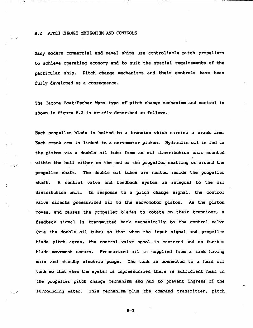
,
B.2‘d
Many
PITCH CHANGE KXHNZISM AND CONTROLS
modern commercial and naval ships use controllable pitch propellers
to achieve operating economy and to suit the special
particular ship. Pitch change mechanisms and their
fully developed as a consequence.
requirements of the
controls have been
The Tacoma Boat/Escher Wyss type of’pitch change mechanism
shown in Figure B.2 is briefly described as follows.
Each propeller blade is bolted to a trunnion which carries
Each crank arm is linked to a semomo tor piston. Hydraulic
the piston via a double oil tube from an oil distribution
within the hull either on the end of the propeller shaftingJ
amd control is
a crank arm.
oil is fed to
unit mounted
or around the
propeller shaft. The double oil tubes are nested inside the propeller
shaft. A control valve and feedback system is integral to the oil
distribution unit. In response to a pitch change signal, the control
valve directs pressurized oil to the semmmotor piston. As the piston
moves, and causes the propeller blades to rotate on their trunnions, a
feedback signal is transmitted back mechanically to the control valve
(via the double oil tube) so that when the input signal and propeller
blade pitch agree, the control valve spool is centered and no further
blade movement occurs. Pressurized oil is supplied from a tank having
main and standby electric pumps. The tank is connected to a head oil
tank so that when the system is unpressurized there is sufficient head in
the propeller pitch change mechanism and hub to prevent ingress of the
4 surrounding water. This mechanism plus the command transmitter, pitch
B-3 1

u
1. Propol!wPropel!cr bladeB’.llscZealaouble suppo’ted!):?dc!“un~IOfl
Mlust, nq crankTr.;~n80n nut
~1 lkC,:SS head with
dsublc suppodedadlustlng rodSewomotot piStOn
P~o~eiler hubSewomotor cylinder
II. Propeller Shaft:1 pr~:ec:lng hood for
fs”onalle? shaft flange;: su~h,nq Of stemtube
seal*S P,eae!!cf skaft?: Csaol,ng flanqe“j ~:uI:IC 011 tube
III. 0;! distribution Unit
Figure B.2.
0,1 ~,s!:. button shaft
all dls!fibutlcn baxkouslnglrn:e.mcdla!e shaftCantrol housingFeedback system
2? Control valve22 P, Jot valve
IV. Hydraulic Control System23 Main and standby .
control 011 oumctWith elcctflc motor
24 Suction tank(yard”s supply)
2S Head oil tank26 Oil litter
27Ottcooler28 Hand pump for
mec~an{cal
Iock, ng device
~ MedtanlcalIoculng device,
V. RemoteControlandpitchIndication~; Command transml:tef
31 SlaVe Jnlt32 klechanlcal cannec!ion
~yafd”s S&PPlyl~~ ?I:* setter3J +~ndwl=eei for total
eme~ge-ty cantrol~j hfechanlcal pI!c!l
l-fdicatlon:6 A:tualPitch
:ransmlttef37Pttb Indicator
Typical Pitch Change Mechanism and Controls
L’
J
B-4

indicator, and normal hydraulic system components comprise a reliable and
Jsimple pitch change mechanism and controls. Provisions are made to allow
.
emergency local control in the event of hydraulic failure.
B.3 THRUST BEARING
For the ventilated propeller installation, the sidehull construction in
the area of the stern and transom permits placement of the thrust bearing
assembly entirely within the sidehull and much closer to the propeller
hub than in conventional displacement craft. The proximity of the stern
bearing to the thrust bearing permits mounting both bearings in a common
housing, with both bearings being lubricated and cooled by circulating
oil. This assembly is called the Thrust Bearing Module. See Figure B.3.
---”
Loads are generated
vertical directions.
there is a bending
by the ventilated
as well as in the
moment generated by
propeller in the lateral and
axial direction. In addition,
the eccentric thrust of the “
partially inmersed propeller, and the weight load of the propeller itself.
By designing the stern bearing and the thrust bearing into a common
housing. the two bearings are made to react the lateral loads, the thrust
loads, and the bending moments generated by the propeller, while
minimizing the risks due to wear and misalignment normally associated
with water-lubricated stem bearings.
The design speed of the propellers makes possible the use of a high
capacity, tapered-roller thrust bearing to absorb both the forward andd
B-5
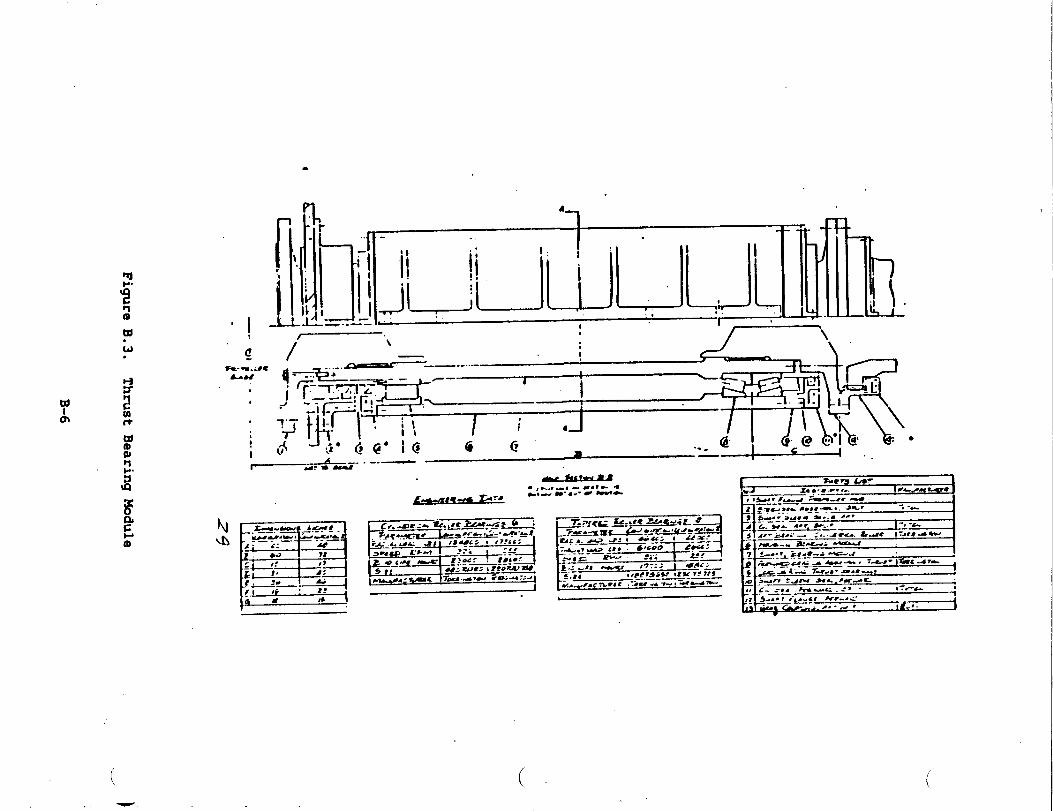
●
-6!5 ~“
.—-..
.—
.
J-
1
—-_-J7
..-J
I3 -..-,-7.-—.
.—-...-1
--- J.—.1
r_,...r—4 ‘7.....
M
.-e
,---—I
.-“w
;
FigureB.3.
ThrustBearingModule
reverse thmst of the propeller, and a high-capacity cylindrical roller
-.--’ bearing to react the loads and moments due to the combined effects of
propeller weight, vertical thrust, lateral thrust, and offset axial
thrust. “
The radial bearing is located aft, closest to the propeller. to minimize
the propeller shaft bending moment.,
fo=ard end of the “housing to react
the lower radial loads that occur at
The thrust bearing is located at the
the axial thrust of the propeller and
this location in the drive line.
The propeller hub is flanged-bolted directly to the aft flange of the
thrust bearing module. The aft half of the gear coupling that connects
the propeller to the gearbox is flanged-bolted to the forward end of the
bearing module.
d
The thrust bearing module is foot-mounted in the horizontal plane that. .
contains the shaft centerline, to minimize the load on the hold-down
bolts from the axial thrust of the propeller. Since both bearings that
support the propeller are oil lubricated. rolling contact assemblies,
progressive wear and resulting misalignment that occur in-.
water-lubricated stern bearings are eliminated. This feature is of
particular importance when considering the complex loading into the
bearings and hull structure that occur with ventilated propellers, and
the compounded adverse effects -that wear in the stern bearing would
produce.
‘,dThis module incorporated one cylindrical roller bearing that accommodates
only radial loads, and a pair of taper~ roller bearings in a ‘TDI’
B-7
,
mounting, to accommodate axial thwt in either direction while providing
for slight angular misalignments resulting from shaft deflections. Allu
bearings are lubricated by circulating oil that is filtered and cooled by
the system that serves the propeller gearbox. Lube oil to the bearings
is supplied by a number of jets evenly spaced around one side of each
bearing annulus. The oil to the thrust bearings is fed by separate jets
on each side of the assembly, from where is
the space between the outer races, then to
to a sump; the oil is pumped from this sump
flows through the bearings to
the groove and a gravity drain
to the sump in the gearbox.
Horizontally split oil seals are
All parts in each seal assembly
installed at each end of the
may be inspected and replaced
disturbing the bearings or removing the module from its mounting.
Bearings are secured and clamped by hardened steel rings that are
to the proper axial fitup at assembly.
module.
without
. w’
shimmed
The bearing housing is nade from a steel welkent that is stress relieved
prior to final machining. The housing is bolted to the ship’s structure
at two flanges that extend radially outward from the housing, with the
bolting surface lying in the horizorital plane that contains the shaft
centerline. This construction minimizes eccentric loading of the module
housing as well as of the ship’s structure under the action of the
propeller thrust.
All exposed parts
corrosion.
of the bearing module are treated and coated to resist
-;
B-8
B.4 DRI~ -S AND COUPLINGS,“.-’
In order to reduce weight, forged tubular drive shafts are used to
transmit torque from the gearboxes to the propeller. Shaft weights are
reduced to about 50 percent of the weight of a solid shaft operating at
the same design stress. In the case of the propeller shafting, the
central hold is used to route the hydraulic oil feed tubes for the
controllable pitch propeller from the control unit. located on the
forward side of the gearbox, to the propeller hub outboard of the thrust
bearing module.
*
All shafts are machined from through-hardened alloy steel, and are
designed for combined stresses in bending and torsion that do not exceed
10,000 psi at the maximum load conditions. Exposed sections of shafting[d
are coated to resist
i
Torque through the
corrosion.
thwst bearing module is transmitted by means of
flanges splined, piloted. and bolted to the shaft ends. All splines are
registered by means of a long pilot on each side of the spline. In the
thrust bearing module the replaceable seal sleeves are clamped by the
bolting interface for the spline to minimize the number of loose pieces:
the seal sleeves serve also as the clamping rings for the inner races of
the radial and thrust bearings.
The size of the drive shafting in each configuration was determined by
the bore size of the thrust bearing required to react the propeller.
thrust load. An additional factor was the need for a hollow shaft ind
,
which to install the piping and control transfer mechanism for the
controllable pitch propeller.
The weight”of the drive shafting was determined by the outside diameter
and the design stress level. The shafting for these applications is
designed primarily to transmit the torque from the gearbox to the thrust
bearing mdule, with a very minimum of bending. The radial loads and
bending moments due to the ventilated propeller are reacted by the
bearings in the thrust bearing module (thrust block) at the transom. The
shaft bore size was determined on the basis of the allowable torsional
shear stress, which was set at a maximum
engine torque.
The shaft sizes for both propulsion plant
from these considerations, are tabulated in
value of 6000 psi at maximums
A preliminary survey of available
torques for both propulsion plant
J
configurations, as determined “
Figure B.3. u’
_ COUPLINGS
Because of the low propeller speeds in both configurations, the large
propeller shaft torques are beyond the range of most coasnercially
available flexible couplings. Flexible couplings are considered
necessary to accommodate misalignments, therad differential expansion
between the steel machinery and the aluminum sidehulls, and distortions
in the sidehulls due to conditions that include off-cushion and -
on-cushion operation under wide ranges of loading in various sea states.
couplings indicated that the propeller
configurations exceed the capacities of
-}
B-10
.. —.“
commercially available disc and diaphragm couplings. Available
._.”grease~lubricated gear couplings manufactured by Zurn (Reference 6) were.
found to have torque capacities adequate not only for the present torque
loads, but for torque loads well in excess of present requirements. In
the torque ranges in which disc couplings are available, the weights of
the disc and gear couplings are comparable. Therefore, it is expected
that no weight penalties will develop when gear
the subject drive lines. From the layouts
developing the concepts for the thrust bearing
couplings are.applied to
made in the course of
modules, the proportions
of the
thrust
gear couplings are consistent with those of the shafting and the
bearing modules.
B.5 WATX PERFORMANCE
.--’
Conceptual waterjet installations were reviewed to provide comparative
inputs to the propeller selection process. Figure B.4 shows that, in
general, waterjet propulsory have a lower efficiency than propellers.
This reflects directly on range and speed performance. The conclusion is
confirmed by comparison of the ALRC PHM waterjet pumps and ventilated
propellers shown in Table B.1.
For low speeds, i.e., about 18 hots, the
waterjet propulsion were calculated using
SAC24195V20RVR diesel engines. This is
thrustlefficiency values for
two PJ-24 pumps powered by
in accordance with current
practice for waterjet propelled ships whereby a separate cruise or low
speed propulsion mode is furnished by a separate system. Examples of“
these cmise systems include the PHM hydrofoil, the “American Enterprise”4
crew boat and “HMB Speedy”, a hydrofoil patrol ship very similar to the
B-n
*
“Jetfoil” hydrofoil ferry.
would drive the lift fans
the maint UK2500 engines.
For the NASW SES the cruise
in the cushion-borne tie when
waterjet diesel
vpropulsion is by
The values of thrust given in Table
waterjets would give approximately
when compared to two propellers
B.1 show tlpt for the NASW SES, two
5 knots less off-cushion top speed
and approximately 10 knots less
on-cushion top speed. These differences do not take into account the
weight differences of the two installations which are judged to
favor of the propeller
entrained water in the
would affect, primarily,
ship propulsion machinery largely because
inlet ducting and waterjet pump. This
range since less fuel could be carried.
be in
of the
weight
In view of these results, waterjets are eliminated early in the study~
phase.
B.6 FuLLY~ PROPELLER
A brief study of a fully submerged trans-cavitating propeller was sized
to verify its suitability as a backup to the baseline partially submerged..
ventilated propellers. The performance appears to be acceptable and
could be implemented if required.
~ PROPELLER PERFORMANCE
Submerged propellers were selected using cavitation tunnel data. This.
data contains the effect of blade area ratio, pitch angle and cavitationG}
B-12

—. . .
( (Table B.1. Comparison of Waterjets and Propellers (1500LT)
ShipSpeedKnots
15
(1) 18
22
30
(2) 40.
50
EnginePowerSHP ‘“
3700
3700
3700
22,500
22,500
22,500
Two WaterjetsThrust EfficiencyLb
46,000 .29
42,000 .31
38,000 ● 35
153,776 .33
141,920 .41
(1) Off-Cushion
(2) On-Cushion
(3) Rated engine power - 2 engines per ship
130,847 .48
Two PropellersThrust EfficiencyLb
72,134 .46
72,127 .56
67,159 .63
207,749 .44
206,791 .58
189,788 .67
IF-I-13

index of the water velocity approaching the
the submerged propeller is good performance
hots and at low speeds. Characteristics of
N&nber of Blades 3
Blade Area Ratio 0.48
Hub/Tip Diameter Ratio 0.3
propeller. An advantage
both at speeds of at least
the chosen design are:
of
\_50
Thrust/Disc Area Less than 1000 psf
Appendage Hull 0.91
Diameter 11.6 ft
214
N PROP .72
NGB .97
N BRGS .98
-.
The efficiency losses associated with each propeller type installation
and the uncertainties associated with each installation differ. For the
ventilated propeller there is little drag associated with its ‘
installation. A small fairing before the propeller boss and a rudder
forward of the propeller are used on each sidehullt for the submerged
propeller there is judged to more drag associated with its installation.
A suxmary of rudder and appendage drag aspects follow.
RUDDER DRAG
Ventilated Propeller
o Larger area rudder not in
jet.
Submerged Propeller
propeller o Smaller rudder in propeller jet..
B-14

. .
Jo Propeller jet swirl not reduced o Propeller jet swirl reduced by
by rudder ahead of propeller disc. rudder; can increase propeller
efficiency.
o No propulsion benefit from rudder. o Possible efficiency benefit
Effect of madder flow into requires evaluation but
propeller requires evaluation but estimated small.
estimated s-11.
OTHER APPENDAGE DRAG
o Propeller hub drag is assumed o
included in Navy performance
do No stints, bossings, shaft
fairings.
&ta.
o
0 Drag of hubtthrust bearing module o
fairing ahead of the propeller not
included in performance.
o No appendage drag used in
ventilated propeller performance.
Requires evaluation.
Propeller hub drag included in
Newton and Radar data.
.’
Drag associated with struts,
bossings and shaft fairing.
Appendage drag of 9 percent
included in submerged propeller
performance predictions based on
plaming craft data. Requires
further evaluation for SES
craft.
Both propeller types have been successfully demonstrated at high ship
speeds. The ventilated~-
submerged propeller type
propeller is fitted to the SES-IOOB. The
has been fitted to 50 knot craft and has
B-15

performed well. At this time adequate performance for the NASW is
indicated using either propeller type based on available data.
B.7 WEIGHTS
Weight esti-tes for the lift and propulsion equipment have been made
based on manufacturer’s data for standard off-the-shelf machinery,
responses to requests for quotation where special equipment was involved
and on designs and calculations based on the installation layouts. Al1
components and subsystems have been sized in accordance with the
performance requirements. The total weight
and propulsion systems
each SWBS 3-digit group
is 238 long tons.
follow.
DIESEL WGINES (SWBS 233)
Four engines in two sizes are used for
drives; these are the SAC24195V12RVR’S and
engine weights, including their respective
are from catalog information.
of the equipment for the lift
Descriptions of the items in
the propulsion and lift fan ,
two are SACM 195V20RVR’S. The
stan&rd accessories packages
TURBINES
An LM2500 gas turbine engine in production by the General Electric
Company is installed in each sidehull. The exhaust collectors are
included as part of the engine weights. The weights of the lube oil
systems external to the engine are included in SWBS item number 262.
‘u’
B-16
GEARING.
.
There are six gearboxes in the lift and propulsion system; four are
modified versions of standard parallel-shaft increase and are used in the
lift system drives; the other two are special combination
parallel-shaft and planetary gearing and are used in the
system. Weight estimates for the lift fan gearboxes are based
designs of
propulsion
on catalog
data; the weights of the gearboxes for
preliminary design layouts developed by
lube system weights for all gearing are
the propeller driven are based on
the Cincinnati Gear Company. The
included in SWBS item number 262.
CLUTCHESANDCOUPLINGS (SWBS 242)
The weight of equipment in this category comprises those components ,d
installed or mounted remotely from the engines and gearboxes. Included
in this group are the flexible couplings between the propeller gearboxes
and the propeller assemblies. and the overmanning clutches installed
between the gas turbines and the propeller gearboxes.
SH?WZING AND SEALS (SWBS 243)
The weights in this category include only the shafting and seals that are
separate from equipment such as the ertgines. ge=bxes, fans. etc.? and
involve primarily the lift fan and propeller shafting and the stem seals.
B-17

BEARINGS (=S 244)
u
Included are the special bearing assemblies designed to support the
propellers”and the aft ends of the turbine engine shafts. The weights of
all other bearings are included in the weights of the equipment in which.
they are installed.
PROPELLERS AND CONTROLS (SWBS 245)
The
and
weights tabulated comprise those of the controllable pitch
the associated hydraulic actuators and controls, including
propellers
piping and
valves. The weights of the propeller shafting and thrust bearings are
listed under SWBS 243 and 244, respectively.
LIFT FANS (SWBS 248)
Six lift fans are installed, two forward and two
fans are the same size and capacitY. The
inter-connecting shafting, couplings, and the
installation.
COMBUSTION AIR SYST= (~S 251)
in each sidehull. All ‘
fan weights include
ductwork required for
This equipment comprises two sets of demisters and filters, one set per
sidehull, to condition the combustion air for the gas turbines. Included
are the weights of the acoustic treatment and the anti-ice equipment for
the duct walls.>}
B-18
.
PropulsionControl (SWBS 252)d
.
The propulsion control equipment comprises the controls and monitoring
equipment for the gas trubines and the diesel engines, but does not
include the controls for the controllable gas propellers, which are
included in SWBS item number 245.
Uptakes (SWBS 259)
The weights of the uptakes include the weights of the exhaust ducting for
the gas trubines and for the diesel engines..
Lube Oil Systems (SWBS 262)
d
The lube oil systems comprise the main pumps, auxiliary pumps, heat
exchangers, filters, valves, and piping for the gas turbines and the lift
fan and propulsion reduction gears. The
engines are included as part of the engine
item number 233.
lube systems for the diesel
accessories packages in SW’BS
Operating Fluids (SWBS 298)
The weights of the operating fluids include the lube oil and cooling
water for the turbines, diesel engines, and the lift fan and propulsion
gearboxes.
B.8:TECHNICAL RISKd
B-19
.
The following subsections are a discussion of the technical risk for the
prime movers, the propulsory. and the reduction gearing.“._.
B.8.1 PRIl& MOVERS
The ancillary system for the
art. The air inlet system,
by-pass provisions, anti-ice
prime movers are all within the state of the
a combination of ducting, demisters with
systems and noise suppression measures have
all been applied to modern ships in commercial and Navy service with
excellent results. The inlet system for the SES is a completed design
which was fully model tested for performance during the 3KSES Program.
All gas turbine and diesel powered craft and ships have similar air inlet
systems. Similarly, exhaustluptake systems, usually comprised of gas
turbine and diesel connections, ducting, sound suppression materialtitemsw
and weather closures, are well known, within the state of the art and
show good service.
DIES&L WINES — The MTU 16VS38TB82 and alternative engines are
representative of modern, reliable, high specific power, high speed
diesels being used in increasing numbers for all
world-wide. These engines are fully developed mgged units
economy at part and full load and are considered low risk.
applications
with superior
GAS TURBINES — The GE LM2500 gas turbine is a fully developed free
turbine unit currently in Navy inventory. Service experience includes
the DD 963, the FPG 7, the PHM and ships of foreign Navies. There is low
risk associated with its selection:
B-20
—-
REDUCTION GEAR — The reduction gear design is a low risk conservative,
state-of-the-artJ design furnished by the Cincinnati Gear Company. The
been compromised by s-11 size, weight or low cost
would reflect on reliability. Premium grade steels and
design has not
approaches.which
conservative stress levels combined with a rigid casing, generous bearing.
areas, high capacity lube supply and fully factored loadings give
confidence in the design. The reduction gear designs which are proposed
do not require developmental activity or unusual manufacturing techniques.
Comparable in-sewice reduction gears designed and manufactured by the
Cincinnati Gear Company include the parallel offset reduction gearhx for
the Boeing Jetfoil
American Enterprise
and the combined droptepicyclic gearbox for the
craft.
u B.8.2 PROPULSORY
is considered to be the lowest risk. klany have been,
being used, for high speed naval craft such as the PC
are therefore experienced in the manufacture of these
Of the propulsory evaluated, the submerged (conventional) propeller for “
high speed craft,
and are currently
and PCG. Vendors
propellers and much is known about propeller blade performance. ‘The high
speed ventilated propeller blade does not enjoy the benefit of previous
service experience except in the SES-1OOB test craft and many smaller
racing craft. It follows that manufacturing expereince for the
ventilated propeller is lacking.
Pitch change mechanisms and controls have minimal technical and
wproducibility risk when associated with submerged and ventilated
B-21

.
propellers.
naval ships.
These systems are now employed extensively on commercial and
The same mechanisms and controls associated with ventilated~,
propellers also have low risk because of the extensive experience with
these mechhisms on large tankers and are carriers that routinely operate
partially submerged in a
B. 9 CCMPONENT AND SYSTEM
The selection
configurations
ventilated condition while transiting in ballast.
RELIABILITY
process for the equipments for the propulsion machinery
used reliability as one of the driving parameters. The
high reliability of the chosen equipments with the diesel engines used
for lift power for off-cushion operations assures a very reliable ship.
Redundancy for off-cushion is provided with the gas turbines, however,
they will be operating inefficiently on the low end of their power
curve. This case then, would be for emergency operation only.”u
The M’TU diesels and the LM2500 gas turbine have been proven reliable.
The U42500 is currently in Navy inventory. The diesels are in
commercial/industrial and European naval use. The combination of engines
chosen for the arrangements offers an efficient reliable match.
The propulsion transmission trains feature Cincinnati Gear Company
gearbox designs. These designs utilize conservatively loaded gears and
journal bearings which result in gearboxes that are durable and
reliable. A typical
reliability evaluation
effect Ship Technical
combat mission profile was used as a basis for
(Reference: Medium Displacement Combatant Surface
Report, April 1981). This profile does not have hL ~
any operational conditions that would affect the inherently high
B-22
reliability of the proposed gearboxes, which feature conservatively
d’
designed helical hears mounted in journal bearings. The SSS overmanning.
clutches and the air clutches that are used to engageldisengage the
diesels aie mounted on the outside of the geartix. These clutches are
reliable and coumonly used in marine arid industrial applications. The
demisters and exhaust system in all configurations are of straightfomard
design and are not considered to be reliability-critical. These
trains will be very reliable in any of the configurations presented.
power
The Tacoma Boat/Escher Wyss propeller design includes the pitch controls,
instruments, sensors, the hydraulic system which contains pumps,
hydraulic controls, oil collers, filters, valves and fittings, the
propeller and the pitch change mechanism.
d
Since the ship thrust and the ship maneuvering capability are dependent
on this system, high reliability of these parts are mandatory. The
Tacoma Boat/Escher Wyss propeller and associated equipment, has proven
capabilities on previous designs. The highest probability of failure
occurs in the elements of the hydraulic system. For this reason.
redundancy in pump and controls is provided. Additional redundancy is
provided in the manual control. In the event of a complete breakdown of
the hydraulic system, the propeller can be mechanically locked in an
ahead position by means of the linkage between the propeller blades and.
the double oil tube.
B.1O MAINTAINABILITY ASSESSMENT
4The maintenance philosophy for the SES is minimum preventive maintenance
B-23

while operational. Corrective
to removal and replacement
philosophy dictates a total
maintenance onboard ship will be limited
of mission-essential equipment. This ‘w
maintenancee concept that dennnds high
reliability parts with most maintenance perfomed while the ship is in
port. .
Removal and replacement of major items is discussed in 4.3.2.1. The
following maintainability criteria were applied in developing the
concepts described in this report.
a.
b.
c.
d.
e.
f.
9“
h.
No secon&ry equipment removals required for access.
Adequate access doors for all equipment with sliding or.
hinged covers.
No structural cutouts for equipment access.
Adequate access around all equipments for inspections,
checks, adjustments and corrective in-place maintenance.
Cathodic protection for dissimilar metal joints.
Stan&rdization of fastenerslpartslmaterials.
Quick disconnect latches. cables, lines, etc.
Minimizing special
All the heavy components
tools and test equipment.
such as gear boxes, engines. etc., will
have lifting lugs. Maintenance rails are
removal paths through combustion air inlet or
major equipment.
provided on special
the fan air inlet for
w
B-24
The Escher Wyss propeller is a highly maintainable design. The
Jmechanical pitch change mechanisms in the propeller hub is designed
for the life of the ship and requires no maintenance. The hydraulic
activation” system which requires some maintenance is installed in
the shafting within the ship. Accessibility is provided for all
scheduled and unscheduled
itself. Access from the
satisfactory for the various
maintenance required in the mechnism
engine room around the equipment is
installations.
Escher Wyss has estimated a 6.9 hour MTTR for the hydraulics and
controls. Ready access for these systems on the machinery
arrangements presented assure that the baseline MTTR will hold at
6.9 hours.
4All similar parts, including
without additional machining
maintenance is minimal involving
B.11 PRODUCIBILITY
repair parts. are interchangeable
or selective assembling. Daily
oil level and oil filter checks.
All components and assemblies for the Propulsion system
Configuration have a solid manufacturing base relative to
state-of-the-art practices, tooling and machines.
The gas turbine and diesel engines are in series production.
d
B-25

The reduction gear designs as selected by RMI and Cincinnati Gear do
not present producibility problems beyond learning curve development
during manufacturing and test of the first reduction gear set.
Propeller size and materials for fully
pose producibility problems
propellers in similar materials
service both in commercial and
propeller, there my be a need
since
submerged propellers do not
much larger conventions1
have been manufactured and are in
naval ships. For the ventilated
for manufacturing development since
L,
the blades will be made of harder and tougher alloys to resist the
generally higher steady state and alternating stress levels used for
ventilated propellers. It is held, however, that overall, the task
of producing either a conventional submerged propeller or a
ventilated propeller is about the same providing some manufacturing\./
development is perfomned on the ventilated propeller.
The other aspects of the propeller, the CP mechanism and controls,
present no producibility problems, being state of the art and
familiar to vendors.
The thrust bearing module and shafting are custom designed. They
present no producibility problems. The bearings and couplings are
catalogue items and seals are similar to items in service.
B-26

---’
B-1. Propellers for High-Performance Craft, by J. L. Allison,Marine Technology. October 1978.
B-2. Tacoma Boat/Escher Wyss Catalogue No. e21.25.33 R Cha 35.“Escher Wyss Propellers.”
B-3. Medium Displacement Canbatant Surface Effect Ship. TechnicalReport, PMS-304, Draft, April 1981.
B-4. Performance Data of Propellers for High Speed Craft by R. N.Newton and H. P. Rader, Royal Institution of Naval Architects.1961.
B-5. Torrington Bearing Catakgue No. 1269.
B-6. Zurn Mechanical Power Transmission Handbook - Manual No. 564.
B-7. Tyton Drawing No. TRO1-18.75-D (Stern Seal).
B-8. Tyton Drawing No. TRO6-10.OOO-C (Oil Seal).
B-9. 3000-Ton Surface Effect Ship Producibility Improvement Plan,Appendix A - Statement of Work for 3000-Ton Surface Effect
dShip Producibility Improvement, 28 May 1981.
B-10. Surface Effect Ships Propulsion Technology Man-l, Vol. III.page 4.3.16-3, PMS304.
B-n. Tandem PSSCP Machinery Plant Final Report. CDRL AO04, BellAerospace, New Orleans, Dec. 1, 1978.
B-12. 3000-Ton Surface Effect Ship Producibility Improvement Plan,Appendix A - Statement of Work of 3000-Ton Surface Effect ShipProducibility Improvement, 28 May 1981.
B-13. Propulsion and Lift Systems Summry Report (Preliminary), CDRLNo. E06C, RMI, Inc., 1 Spetember 1981.
B-14. Navy Letter Reference PMS304-20:RRB:SVS, Ser. 3046, 29 July1981.
B-27

—.——... .
APPENDIX C
STRUCTURAL DESIGN
‘.--’
C.1 RATIONALE FOR USING RELIABILITY BASED METHODS
This appendix summarizes the rationale and methods used to estimate
structural weight and provide structural design criteria for structural
design when reliability based load and design methods are used.
The order of presentation is as follows: section C.1 provides the
rationale for using reliability based methods, especially for vehicles
for
the
C.3
which a large experience base does not exist; section C.2 presents
method for developing loads and shows how it can be applied; section
discusses design and fabrication..
It has been found from experiments that the cause of the greatest load
acting on a ship’s structure is different for different ship types. Ford
a monohull, the longitudinal bending moment arising from differences
between weight and buoyancy loads (W-B load) is dominant; for a SWATH,
the transverse bending moment due to forces acting on the sidehulls is
largest or dominant; while for SES’S the off-cushion longitudinal load
due to head sea slaming in suxwival sea states is dominant.
A reliability based method of selecting design loads was selected for the
SES as a large historical &ta base does not yet exist. This method
makes possible the extrapolation of experimental and service data. as.
well as analytical results. The reliability approach allows the direct
use of results obtained from consideration of first principles in the
various disciplines associated with ship design, and shows the effects of
.-J the variables of interest upon structural weight and reliability.
c-1

In summary, the use of reliability based methods for design allows
technology independent evaluation criteria to be established
comparing ship types or variants within a given ship type and gives
engineer or project manager a method for evaluating the effect
proposed reliability level changes upon the mission effectiveness and
for w’
the
of
the
cost of
C.2 USE
the design.
OF RELIABILITY ?4EZIiODIN PREDICTING STRUCTUI??LWEIGHTS
Structural weight is a function of the operational profile (the table of
the lifetime hours spent in each.sea state and speed for each operating
mode), the required reliability, the simultaneously acting loads, the
materials used. and the design stress analysis methods employed.
In order to make clearer the origin of uncertainties in load and strength‘.-”
estimation, please refer to Figure Cl. Figure C.1 shows four
probability density (not probability) curves. The curve on the left .
shows an experimental or parent probability distribution. The two curves
in the middle show the probability density of the largest load plotted.
against load magnitude for two different experimental sample sizes. The
right-hand curve
(resistance) of the
shows the probability
structure plotted against
density of
applied load
the strength
magnitude.
The distribution curves shown in figure C.1 may be thought of as arising
in the following manner. First, a largest load distribution curve.
Suppose that a large number j of experimental -s to measure loads are
made in a random seaway, each - of which has a number of wave‘e )
.
c-2
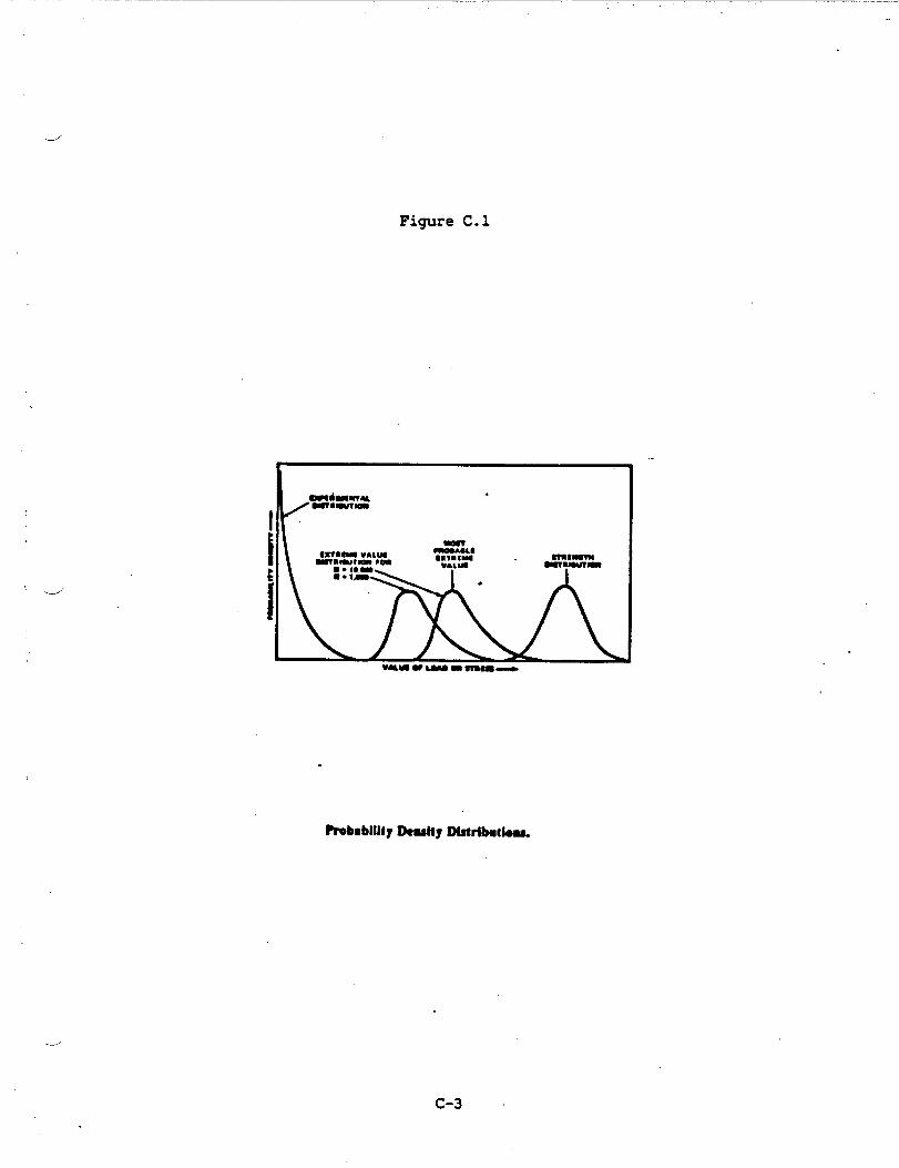
Figure C.1
_/
.
?robabllltyLkuhy Dlstrlbdou
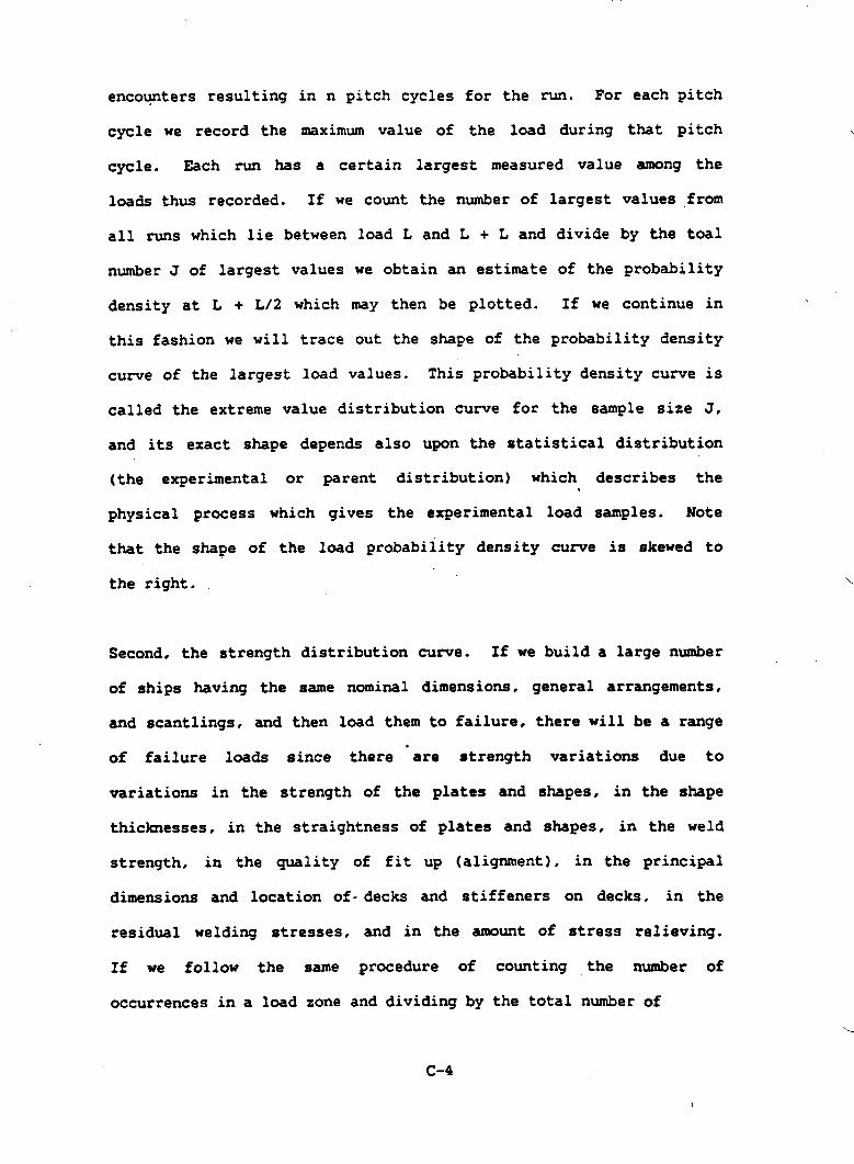
encounters resulting in n pitch cycles for the run. For each pitch
cycle we record the mximum value of the load during that pitch
cycle. Each run has a certain largest measured value among the
loads thus recorded. If we count the number of largest values from
all runs which lie between load L and L + L and divide by the teal
number J of largest values we obtain an estimate of the probability
density at L + L/2 which may then be plotted. If we continue in \
this fashion we will trace out the shape of the probability density
curve of the largest load values. This probability density curve is
called the extreme value distribution curve for the sample size J.
and its exact shape depends also upon the statistical distribution
(the experimental or parent distribution) which describes the.
physical process which gives the experimental
that the shape of the load probability density
the right.
load samples. Note
curve is skewed to
Second, the strength distribution curve. If we build a large number
of ships having the same nominal dimensions. general arrangements,
and scantlings. and then load them to failure, there will be a range
of failure loads since there “are strength variations due to
variations in the strength of the plates and shapes, in the shape
thicknesses, in the straightness of plates and shapes, in the weld
strength, in the quality of fit up (alignment), in the principal
dimensions and location of-decks and stiffeners on decks, in the
residual welding stresses, and in the amount of stress relieving.
If we follow the same procedure of counting ,the number of
occurrences in a load zone and dividing by the total number of
c-4

occurrences and plotting resulting values we
-d shape of the strength or resistance probability
Note that most probability density curves
will approximate the
density curve.
have a peak. The
magnitude of the load corresponding to the peak of the extreme load
probability density load is called the most probable extreme load,
and corresponds to the most Often occurring. or most likely extreme
or largest value measured during a test of many samples. The
magnitude of the load corresponding to the peak of the strength
curve is called the most
The shape and magnitude
probable strength.
of the largest or extreme load cu~e can be
found by applying extreme value theory, Ref. C-1. to the results of
experimental tests. The exact shape and magnitude of the structural
ustrength (resistance) curve is unknown, but ongoing work is aiding
in the delineation
are made: first.
secondly, that the
of this curve. In the meantime, two assumptions
that the shape of the curve is Gaussian, and
overall strength of the ship is taken to be that
corresponding to the yield strength of the material in tension (not
the ultimate strength). “or the buckling strength of local stzucture
as computed wing Navy stan&rd design practice, where the yield or
buckling strength is taken to be that
welded minimum mechanical properties.
conservatism in using this approach
corresponding to using the as
There are three elements of
(1) 99 percent of the welded
joints are stronger than minimum mechanical properties, (2) the
difference in strength between yield and ultimate strength is
ignored, and (3) the post buckling strength of the structure, which---
C-5

may range from 1.3 to 2.0 times the yield buckling strength, is
ignored.L./
C.2 LOAD ESTIMATION
Lead estimation consists of using the operational profile. which
specifies the lifetime hours spent in each sea state and speed
combination. both hullbone and cushiobrne, and then (1) finding
the distribution of loads corresponding to each sea state-speed
combination as a function of exposure time, and (2) finding a fixed
load for design such that the risk of exceeding such fixed load over
all operational profile combinations corresponds to the required
reliability. Risk is here defined to be
reliability). Figure C.2 is an example of an
where the number of lifetime hours is given for
combination. The upper number in each cell is
equal to (1.0 -
operational profileu
each sea state-speed
the lifetime hours.
the lower number is the number of
,
Experimental results show that
head sea encounters in thousands.
there
contributing to SES loads in a seaway
One is due to the difference between
are two physical processes
consisting of random waves.
the weight and the buoyancy
along the ship at any instant of time. The second is due to
slasmning,usually in the bow region, due to ship motion induced by
the waves. Slamming is ~ually dominant for determining hullborne
SES loads since it is often two to six times the W-B load. The
frequency and severity of slamming is a function of speed, wave
height, and wet deck clearance tiv~ the off cushion calm water line.
C-6

.-/’ FIGURE C.2 OPERATIONAL PROFIIJ
.’
-
.,.’
.
,..
““s”fgm *.. .. . ..... .. -..” ,.
.
-.,.:”
.
-,
?.”.-. ,. . . .
-. i..“.-” . .
-. .
“?’.‘g HP$ “.
(
.
s
>
-..... ●
●-’,-.
.
...
c-7
.
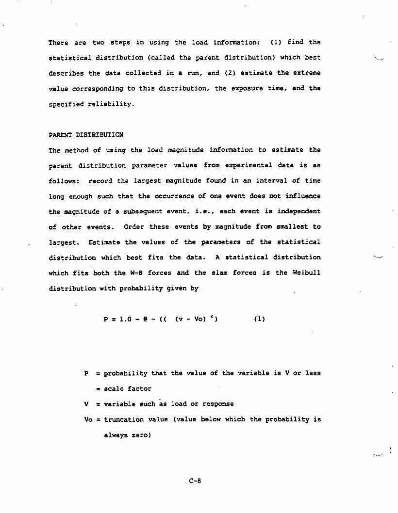
There are two steps in using the load information: (1) find the
statistical distribution (called the parent distribution) which best
describes the data collected in a run, and (2) estimate the extreme
value corresponding to this distribution, the exposure time, and the
specified reliability.
PARENT DISTRIBUTION
The method of using the load magnitude information to estimate the
parent distribution parameter values from experimental data is as
follows: record the largest magnitude found in an interval of time
long enough such that the occurrence of one event does not influence
the magnitude of a subsequent event, i.e.. each event is independent
of other events. Order these events by nuqnitude from smallest to
largest. Estimate the values of the parameters of the statistical
distribution which best fits the data. A statistical distribution
which fits both the W-B forces and the slam forces is the Weibull
distribution with probability given by
P =1.o-@-(( (v-vO)’) (1)
P = probability that the value of the variable is V or less
= scale factor
v = variable such as load or response
Vo = truncation value (value below which the probability is
always zero)
“--’
w )
C-8

!.
.-J
characterizes the W-B “
distribution while c = 1 specifies an exponential distribution which
characterizes a slam distribution. The Weibull distribution has
also been found appropriate as in describing commercial ship loads,
Ref. C-2.
The probability density for the parent (experimental) distribution
is given by
,.
c = exponent
c = 2 specifies a Rayleigh distribution which
P
d Note that if we define x = (V-VO) and substitute we obtain.
and
(2a)
Emlu24E VALUES
The extreme value distribution probability density equation if
f =n t ( p (n-l) ) ~ p (3).
.---’
c-9

Where
f = extreme (largest) value probability density distribution
n= sample size
P = parent probability distribution
P = parent probability density distribution
.--”
The extreme
distribution
encounters or
value distribution is a function of the parent
and the exposure time where n is the number of
events expected during a given exposure time.
The above expression my be directly integrated to give the
probability F associated with qan extreme value
F = P“ (4)
Which for the Weibull distribution as a parent distribution results
in
F= (l-@-(x’) )“ (5)
To find the load corresponding to a specified probability od
exceedance when the parent distribution and sample size are known
solve eq (5) for x to obtain
x = ( in (__lAO_ )) C1.OZC) (6)
(1$0 _ F.’Zm
-)
c-lo
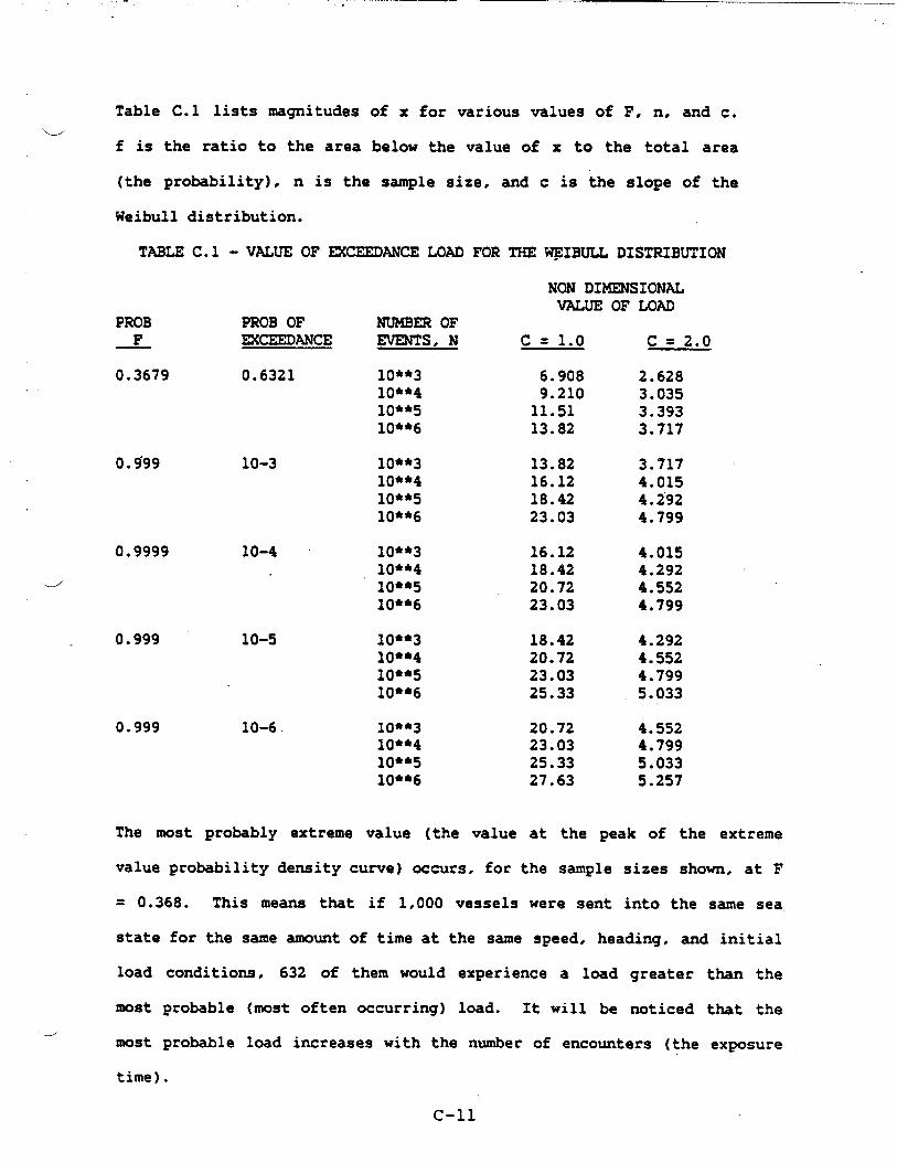
.
Table C.1 lists magnitudes of x for various values of F, n, and c.w
f is the ratio to the area below the value of x to the total area
(the promility), n is the sample size, and c is the slope of the
Weibull distribution.
TABLE C.1 - VALUE OF EK?EEDANCE LOAD FOR THE ~IBULL DISTRIBUTION
PROB_F_
0.3679
0.9999
4
PROB OFmKEEDANcE
0.6321
10-3
10-4
0.999 10-5
0.999 10-6
The most probably extreme
NUMBEROFEVENTS, N
10**31(J**410**51(J**6
10**310**410**510**6
10**310**410**510**6
10**310**410**5lo*~6
10**310**410**510*s6
value (the
NON DIZKENSIONALVALUE OF LOAD
c= 1.0 c = 2.0
6.908 2.6289.210 3.03511.51 3.39313.82 3.717
13.82 3.71716.12 4.01518.42 4.29223.03 4.799
16.12 4.01518.42 4.29220.72 4.55223.03 4.799
18.42 4.29220.72 4.55223.03 4.79925.33 5e033
20.72 4.55223.03 4.79925.33 5.03327.63 5.257
value at the peak of the extreme
value probability density curve) occurs, for the sample sizes shown, at F
= 0.368. This means that if 1,000 vessels were sent into the same sea
state for the same amount of time at the same speed, heading, and initial
load conditions, 632 of them would experience a load greater than the
most probable (most often occurring) load. It will be noticed that the
dmost probable load increases with the number of encounters (the exposure
time).
C-n

o .o .
i-? P. 0 s .
. 0 CJ
DJ
(t0
.0 . m (A
lA
lP
P. G
0 Hln .
I-J
.
ti 0)
P. N m
. H rt
s’t-
.(n
(Y . N
)-w
P-
..
..
0000
0000
0 1-h
NJNNW
..*.
ohJ1.no
0000
.
iDa .,
0000
0000
w .
(.(
( \.
cover a given probability of exceedance. Larger values of c
ucorrespond to non slam loadings. and so current practice from a
structural loads point of view is to have a high wetdeck clearance
hullbome, and to operate on cushion so as to minimize slanming
frequency and slamming magnitude.
=REME VALUE FOR DESIGN
The extreme value used for design is the one for which the risk of
exceedance, over the operational profile, meets the specified risk
of exceedance. For each cell in the operational profile there is a
given risk of exceedance of a specified
exceedance for the entire operational profile
of exceedance for all the cells. In order to-,
load. The risk of
is the statistical sum
proceed we need to a)
find the risk of exceedance in a given cell, and then b) sum”in a
probability sense the risk for all the cells.
a) Exceedance in a specific cell. Suppose the vessel has a
certain strength. Determine the probability of not exceeding this
strength for the operating conditions and duration specified for a
particular cell in the operational profile. For example, the first
line of Table C.3 shows the probability of not exceeding the
strength for operating condition cell one. Denote this reliability =
(1 - 3.62* 10-4) = 0.99963& byFl.
b) Overall reliability and risk. Having found the
reliabilities for each operating cell, find the overall reliability
by using
C-13
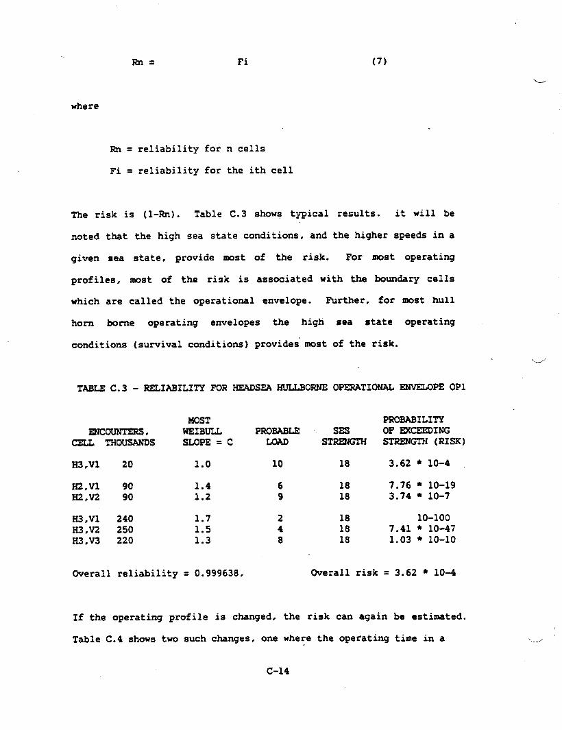
where
Rn= Fi (7)
‘.-.-’
Rn= reliability for n cells
Fi = reliability for the ith cell
The risk is (1-Rn). Table C.3 shows typical
noted that the high sea state conditions, and
given sea
profiles,
which are
state, provide most of the risk.
results. it will be
the higher speeds in a
For most operating
most of the risk is associated with the boundary cells
called the operational envelope. Purther, for most hull
horn borne operating envelopes the high sea state operating
conditions (survival conditions) provides”most of the risk.
TABLE C.3 - RELIABILITY FOR
MOSTmmmrERs , WEIBULL
HEADSEA HULLBORNE OPERATIONAL RIJVELOPEOP1
PROBABLECELL THOusANDs SLOPE = C
N3.vl 20 1.0 10
H2,vl 90 1.4 6U2,V2 90 1.2 9
H3,V1 240 1.7 2H3●V2 250 1.5 4H3,V3 220 1.3 8
Overall reliability = 0.999638,
If the operating profile is changed, the
PROBABILITYSES OF =CEEDING
STRENGTH(RIsx)
18 3.62 * 10-4
18 7.76 ● 10-1918 3.74 ● 10-7
18 1o-1oo18 7.41 fi10-4718 1*O3 ● 1o-1o
Overall risk = 3.62 * 10-4
risk can again be estimated.
Table C.4 shows two such changes, one where the operating time in a
C-14

——.. . . .
e
high sea state cell (OE2) is changed by a factor of 2, and one where a
-.---’
lower sea state cell (OE3) is changed by a factor of 10.
TABLEC.4 - EFFECT ON RISK OF INCREASING NUMBER OF ~COUNTERS
~OPE--OEl--
ENCOUNTERSTHOUSAND RISK
H3,V1 20 3.62*1O-4H2,V2 90 3.74*1O-7H1,V3 220 1.O3*1O-10
OverallEncounters 330
Risk 3.62*1O-4
ENVELOPEN--——OE2——————
ENCOUNTERSTHOUSAND RISK
40 7.25*1O-490 3.74*1O-7
220 1003*10-10
350
7.25*1O-4
ENVELOPE~E3—
mcomrrmsTHOUSAND RISK
.20 3.62*1O-4900 3.74*1O-6220 1.O3*1O-10
1140
3.66*1O-4
The probability distribution for each cell stays the same because
e the sea state and speed are still the same. The change in,
reliability occurs because of the change in the duration or time
spent in a particular operating condition. Note that in both cases
the risk increases (the longer one is at sea, the greater the
risk). If we compare the risk for the two changed operating
conditions 0E2 and 0E3, we see that the risk for 0E2 is greater than
the rask for 0E3 even though the change in the number of encounters
for 0E2 is much less than that for OE3. This example shows that the
overall risk is primarily a function of the severity of the
operating conditions in a cell, and that the overall risk must be
obtained by summing the risk for each cell rather than by summing
the number of encounters. Put another way, the vessel runs a higher
risk
./ than
in a
by doubling the number of hours spent in a sunrival sea state
by increasing by a factor of 10 the number of operating hours
less severe sea state.
C-15 “
CUMULATIVE FATIGUE LOADING
h order to detemine whether fatigue is controlling the stress
level corresponding to a given load must be estimated.
The cumulative fatigue loading may be estimated by application of a
cumulative damage rule such as Miners rule:
.
ni =K (8)
Ni
ni = actual number of cycles at level i
NI = number of cycles at level i to cause failure
(usually
material)
K=. constant
obtained from
of summation,
S-N cu-es for the
L/”approximately 1/3 to
114 for 3 to 4 ship fatigue lifetimes
In order to apply
loading cycles for
known since we have
Miner’s rule, we need to know the number of
each loading intensity. This information is
the experimentally estimated probability density
loading curves which were earlier used to estimate the extreme
values. As before, we estimate the emulative fatiWe ~9e for
each cell, and then sum the c=lative fati~e ~9e for all cells
to find the overall fatigue damage. The stress which is used for “
computation is the nominal stress times the stress consultation
factor applicable at a particular location. If the fatigue stress
found for the lifetime number of loading cycles
cumulative damage stress, then the strength
C-16
is greater than the
of the vessel is

adequate. Due to uncertainties in the order of applied loads, the
vessel is usuallye
times greater-than
required to show a fatigue life which is 3 to 4
the estimated lifetime of the vessel.
An example of such a calculation for an operating cell is shown in
Table C.5. In order to compute the ratio of (actual loading
cycles)/(fatigue life) an experimentally
the material involved is used. For
probability density curve (not the extreme
cuzwe) is used to establish the relation
the number of times such a load occurs.
TABLE C.5 - FATIGUE LIFT CONTRIBUTIONS
detemined S-N curve for
each cell the lifetime
value probability density
between a load level and
OF AN OPERATIONAL CELL
STRESS LEVEL NUMBER OF ACTUAL(INCLUDING STRESS CYCLES To LXFETIME
d CONCENTRATION) FAILURE CYCLES RATIO
70 5X1O**3 1 0.00020050 3X1O**4 7 0.00023330 10**6 41 0.00004110 lo*~8 223 0.000002
Sum for the cell
After finding the cumulative fatigue damage contribution of each
cell, the overall fatigue damage estimate is found by suming the
various cell contributions. The contribution of each cell is not
proportional to the extreme load in each cell, but also depends upon
the number of events and the Weibull slope c for a cell. Finally.
the value of K should be less than 1/3 or 1/4.
. If the value of K is too large then fatigue loading is controlling
C-17
on the section rather than the once in a lifetime load and the
scantlings will have to be increased until the value of K is
satisfactory.
C.3 STRUC_ DESIGN
Structural Design Criteria
The structural criteria specifies the load magnitudes and their
combinations,
properties and
the factors of safety, and sometimes the material
analysis methods of guides to be used.
Combined load sets are the sets of loads which occur simultaneously
on a stmctural element. Each set specifies the overall or global
loads, such as bending and vessel motion loads such as acceleration,
and local area loads such as fluid or point loads. Material
properties, rather than material allowable are specified. This is
consistent with using lifetime loads estimated from actual data.
In order to specify the combined factor of safety to be used in the
case of combined loads interaction equations have to be developed or
modified. Two points should be addressed. First, select the theory
which describes the criteria for the onset of damage to the
material, and secondly, determine how reliability based loads should
be combined with deteministically obtained loads. One possible
equation for estimating a combined factor of safety for tensile
‘..-/
.loads acting in the same direction is
C-18
‘- i
4
Esc = 1.0-
1.0 + 1.0
SY I FSG SY / FSL
SG SL
where
Esc=
FsG=
FSL =
SY=
SG =
SL =
combined factor of safety ( should be 1.0)
factor of safety for global or reliability based loads,
usually equal to 1.0 since the risk is already included
in the -gnitude of the load causing the stress SG
factor of safety for deterministically obtained load
yield stress of lrmterial
stress due to global or reliability based load
stress due to deterministically obtained load
Combined factor of safety equations should be specified for other
combined loading cases including compressive loads, out of plane
loads, and loads acting in different directions in plane.
.MATERIALS
Materials used to date for hulls are high strength marine service
aluminum alloys of the 5000 series. Craft include the SES-1OOA, the.
SES-1OOB, and the SES 200. Both 5086 and 5456 alloys have been
C-19
used. As SES sizes grow larger, the use of high strength steels
becomes attractive, especially those having yield strengths of 80
ksi and above such as HSLA, HY80, and HY1OO. The choice of which
material to use from a weight viewpoint is determined by comparing
the weight of an aluminum structure
sheathing against the weight of a
applications such as minesweeping,
plus any needed fire insulation
steel structure. For special
the use of plastic composites
such as GRP is often worth considering.
Minimum guaranteed (in the case of metals usually the as welded)
properties are nomally specified.
STRUCTURAL DESIGN
Since as SES is supported cushionbome by an air cushion whose
pressure is supplied by lift fans and whose
caused by the cushion pressure, attention to
pays off.
resistance is in part
minimum weight design
Once the structural criteria specifying the combined loads and
factors of safety is available, the remainder of the design can be
carried out by current design techniques including the use of
structural optimization programs such as described in Hughes Ref.
C-3 often
practice as
using, in the -case of Navy designs, current design
analysis guides.
The resulting structure is usually ~ longitudinally framed plate and
grillage structure. Closely spaced longitudinal stiffeners usually
C-20
Iw

result in a minimum weight design. Additionally, large amounts of
-Jpermanent set are often
deck is usually close to
to longitudinal strength.
tolerated in the wet deck area since the.
the neutral axis and so contributes little
Information as to the shape of structural details to minimize
fatigue failure and to estimate the effect to misalignment may be
found, for example, in Ref. C-3.
STRUCTURAL E’AERICATIONNOTES FOR DESIGN
SES’S have the advantage that most of the vessel is composed of flat
panels forming relatively boxlike assemblies. Since the sidehulls
are narrow compared to ships of normal form, they may be shaped
&using flat plate elements joined together rather than being made up
of curved
t.makes the
minimizes
elements. The relatively large amount of flat plate work
use of automatic welding machines quite attractive and
the fabrication cost.
C-21
REFERENCES
Ref C-1 Gumbelt statistics of fitremes
Ref C-2 Hunsee w.? et al.~ “Fatiwe Characteristics ‘f ‘abricated
Ship Details for Design,” Illinois University at Urbana,
Department of Civil Engineering, SSC-318. (Aug
Ref C-3 Hughest @en F*? “ShiP Structural Desi~ -
Based, Computer Aided, Optimization
Wiley-Interscience, (1983)
1982)
A Rationally
Approach,”
‘L.
c-22
\d

w
APPENDIX D
COMPARISON OF PRG AND US SCANTLING DIMENSIONS
-
—
D.1 ALU-ALLOY
.-_.’
Figure D.1 shows the midship
text below.
The MTGsizing
element No. 7,
is provided for
10 and 11 as
stiffenings regarding elements
.
section with elements corresponding to the
smaller plate-thickness regarding the deck
well as smaller profiles of longitudinal
5 to .14.
Concerning the cross-stiffenings, the MTGversion provides for a floor
plate - regarding elements 1 to 4 - instead of T-profiles which are
stated in the US-version. Both results are nearly equal in weight.
i
Within the MTGversion even more weights result from element 12. The
d “M’I’Gversion shows this as “continuous longitudinal wall at _ .8* In the
US-version, this element consists of pillars.
The strength-calculation showed the necessity of this longitudinal wall.
An additional weight is caused by the thicker plate used with the lower
part of element 13.
Different longitudinal frame spacings were selected:
w
US Version: 13 inch (330 xmn)
German Version: 11.8 inch (300 mm)
.
D-1

.
\
14
7
—* ._w— ●
. .
75
?.
Figure D.1. &LEMEW MoML
D-2
.—
*
.

.
Similarly Web frame spacing were different:
w
US Version: Bulk-head spacing in drawing is 60 feet divided by 17 =
35.294 inches = 896 mm frame-spacing.
~G Version: 50 feet = 600 inches = 15.24 m: 15 parts @ 40 inch
(1016 m) frame-spacing.
The comparison of the distance of the longitudinal stiffeners shows, that
the MTG-version is provided for more “longitudinal frames” however less
“web frames”, which means for example: Half a wet-deck-width of 14 ft
(4.267 m) contains 14 “longitudinal frames” in the MTG-version and 13
“longitudinal frames” in the US-version.
..--’
The MTG-version shows for each compartment (600” = 15.24 m) 14 “web
frames” whereas the US-version plans 16 “web frames”.
Steel:
The MTGversion
and principally
shown in the
3.75 kg/m).
shows smaller plate-thickness in
for all elements the smallest
deck-elements 7 and 11
longitudinal frames as
US-profile-list (T-Profile 3x2x0. 125/0, 188 weight
In the US-version the smallest profiles are T 4x2x0, 188/0, 133 with a
weight of 6.728 kg/m.”
-
D-3

That means, the MTGversion contains a reduced weight for “longitudinal
frames” in comparison to the US-version. (The reduction of weight is
2,978 kgfm).
Regarding elements 1 to 4 the MTGversion contains as cross-stiffening a
“floor plate” which is neutral in weight in comparison to the
US-version. Additional weights are given in the ~Gversion
plate-thicknesses within the upper
and 16. Element 1 has been chosen
and lower hull elements
extremely thicker because
with higher
1,2,3,14,15,
it is meant
to be the keel-plate. The thichess for the other elements depends on
the strength calculation.
Table D.1 presents the full structural data for the design described
above.
D-4
)-.
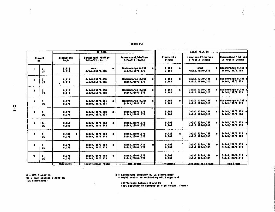
‘?UI
ilpt
*
10us
20us
i=
$0us
40us
5 0us
6 0us
7 0us
t ous
9 0us
1-
(
Tablo 0.1
------ 11 e. -., “e. . .“AL w-
Sl@cMtck@ Lan,sspwf-/balken Rt~nspmf /-bmlkon BlacMtckc Lmssspauf/-balken Rakmenspauf/-bal kenInch T-Profll {inch) T-Profll (inch) (tnch) T-Proftl (tnch} (T-Proftl (Inch)
0,930 Olwc ● Oodemranse 0,2S. ● 0,563 ● Ohuc0,938 6x3x0,2 S0/0,4U 6X3X0,2s0/0,37$ 0,2s0
● Bodenxranee 0,180 64X2X0. 108/0,313 3X2X0, 12s/0, 188
0,81s 6x3x0,2 S0/0,4U Bodenxren9e .,2S0 ● 0,2s0 ● 3x2xo,12s/o*lu, 0.s1s 6xSx0.2S0/0,43t 6x3x0,2 SO/O, S7S
● Oodenxranse O, lU ●
O,lu 4x2x0, lM1/O.313 3X3X0,1 W0,313
0,813 6x3x0,2 S0/0,430 Oodenxmnge 0.2S0 ● 0,2s0 ● 3x2x0 , 12S/0 ,1800,013 6x3x0,2 S0/0,430 6x3x0 .2 S0/0,37S O*IU
● Bodenwmwe 0,100 ●
4x2x0,100/0,313 4x2x0,100/0,313
S,S7S 4x3xo,lso/s,313 ● Bodenxrmee O,2SS ● Coloo Q 3x2xo,12s/o,loo0,37s 4x2xO,1OWO,S13 0xSx0,250/0,43S 0,100
● Boderxwranoe0. 1s0 ●
4X2X0, 188/0,313 6x4x0 , lSO/0,3t3
.
0,37s 3x2x0,12 S/O, \OI ● 6x3x@,2S0/0,37S 0,100 3x2x0, 12S/0, IU ,0 Sx2x0,100/O.313 ●
0,37s 4x2x0,1 U/0,373 6x3x0, 2S0/0, 37S 0,100 4x2x0, lU1/0, 313 4X3X0, 12s/0, 100
0,S63 3x2x0, 12S/0, ltO ● 6x3x0,2 S0/0,37S 0,100 3x2x0, 12S/0, 100 ● Sx2x0, tS0/0,313 ●
0,S63 4x2x0 .lSO/0,313 6x3x0,2 S0/0,375 0,180 4x2x0,100/0,313 4x2x0.180/0,313
0,10s ● 3x2x0, 1?S/0, 110 ● 6x3x0,2 S0/0,37S 0,12s ● 3x2xoo12s/o,loo ● Sx2x0,1t0/0,3t3 ●
0,375 4x2x0,100/0,31S 6x3xO;2S0/0,37S O,tu 4x2x0,100/0,313 3X3XO*12s/0, 100
0,37s 3X2X0, 12s/0, 100 ● 0xSx0,2S0/0,430 Q 0.100 3x2x0, 12S/0 ,100 ● 6x3x0,2S0/O ,37S ●
0,37s 4x2x0, 100/0,31 3 6X3X0, 2s0/0, 376 0,100 4x2x0, 180/0, 313 Sx2x0,100/0,313
0,31s ax2xo,12s/o,lu ● 6X3X0 , 2s0/0 ●a7s 0,1000,37s 4x2x0 , 100/0,313
3x2x0, 12S/0, 10S ●
tx3x0,2S0/0,37SSX2X0.1W0, S13 ●
0,10s 4x2x0 , 1S8/0 ,373 3x2xO,1OWO,313
o . ~ 01-nston Q s ~bxetc~ Zntscken OU-US Olmstoncrus = Amsrikaulsck Otmnsten = Wtcht bmbar in Verbhdm mttLanosspauf(USd~m$ions)
(dt fference between O ●d US(not posstbl. in cwmecthn with lc&t. from)
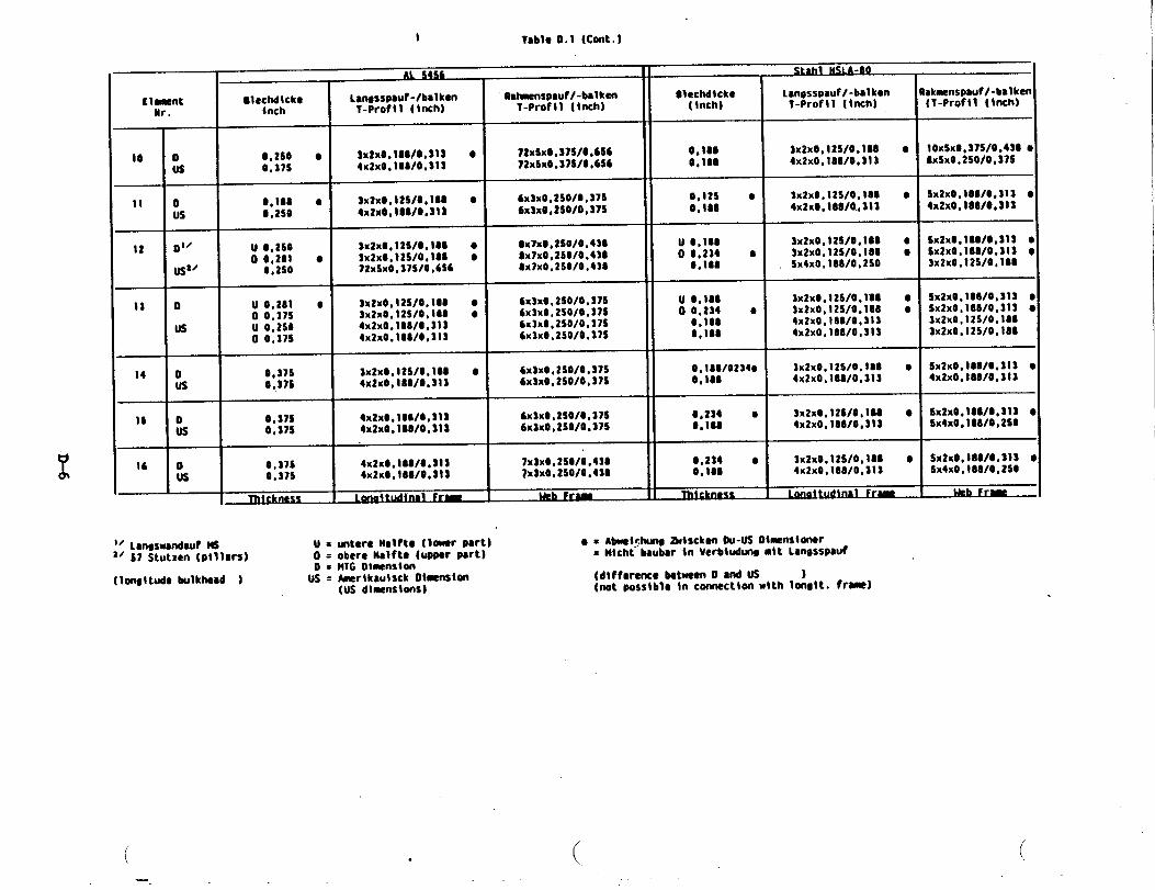
-●
m_.
●☛●
=0
uII
*It
song
●
0--m
om
a--
0“0“0“
=0
>O
ao
1-
um
Na
D-6
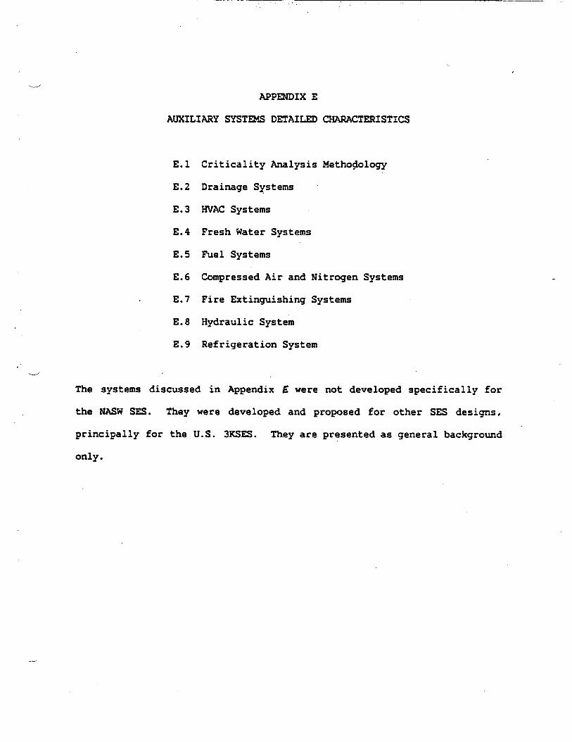
-.-.-’
APPENDIX E
AUXILIARY SYSTEMS DETAILED
E.1
E.2
E.3
E.4
E.5
E.6
E.7
E.8
E.9
>’4“
Criticality Analysis
Drainage Systems
HVAC Systems
Fresh Water Systems
Fuel Systems
CHARACTERISTICS
Methodology
Compressed Air and Nitrogen Systems
Fire Extinguishing Systems
Hydraulic System
Refrigeration System
The systems discussed in Appendix E were not developed specifically for
the NASW SES. They were developed and proposed for other SES designs,
principally for the U.S. 3KSES. They are presented as general background
only.
—

.
APPENDIX E.1
CRITICALITY.ANALYSIS FOR AUXILIARY SYSTEMS
----’
\
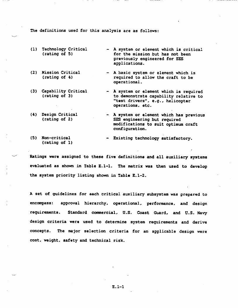
——
.
The definitions used for this analysis are as follows:
-
(1) Technology Critical -(rating of 5)
(2) Mission Critical(rating of 4)
(3) Capability Critical(rating of 3)
(4) Design Critical(rating of 2)
(5) Non-critical(rating of 1)
.--’ Ratings were assigned
evaluated as shown in
the system priority
A set of guidelines
A system or element which is critical
for the mission but has not beenpreviously engineered for SESapplications.
A basic system or element which isrequired to allow the craft to beoperational.
A system or element which is requiredto demonstrate capability relative to“test drivers”, e.g., helicopteroperations, etc.
to these five
Table El-l.
A system or element which has previousSES engineering but requiredmodifications to suit optimum craftconfiguration.
Existing technology satisfactory.
definitions and
The matrix was
Table E.1-2.
.
all auxiliary systems
then used to develop
listing shown in
for each critical auxiliary subsystem was prepared to
encompass: approval hierarchy, operational, performance, and design
requirements. Standard coasnercial, U.S. Caast Guard, and U.S. Navy
design criteria were used to determine
concepts. The major selection criteria
cost, weight, safety and technical risk.
system requirements and derive
for an applicable design were
E.1-1

Table El-l
Page 1 of 2
I
AUXILIARY SYSTEMS
CRITICALITY MATRIX
SwBs RATING506 Overflows, Air Escapes and Sounding Tubes
] 510 CLIMATE CONTROL511 Gmpartment Heating Svstem512 Ventilation System513 Machinery Space Ventilation System514 Air Conditioning System516 Refrigeration System
., 520 SEA WATER SYS=521 Firemain and Flushing (Sea Water) System522 Sprinkler System524 Auxiliary Sea Water System526 ScupPers and fleckDrains528 Plumbing Drainage529 Drainage and Ballasting System
530 FRESH WATER SYSTEMS531 Distilling Plant532 Cooling Water533 Potable Water534 Aux. Steam and Drains Within Machinery Box
(Machinery Drains)536 Auxiliary Fresh Water Cooling
540 FUELS AND LUBRICANTS, HANDLING AND STORAGE541 Ship Fuel and fiel Compensating System542 Aviation and General PurPose Fuels545 Tank ?ieatinq (Diesel Heating)549 Special Fuel and Lubricants, Handling &
Stowage
5———
———
4——
—
ii-—
———
—
T-Yx-————
———
———
—
.——
.
——
xii-——
——
I x .1x 6
x x 9x x 9
x ,11 1 I
I I 1
ZEEE
+Ex 6
xlxl
xx 5
Exl
x 2xlxl
x 2
Bxx 9xx 9
xlx 2
I I I
L.-’;
. E.1-2

— —“
Table El-l (Cont.)
Page 2 of 2w
.-...’
AUXILIARY SYST~
CRITICALITY MATRIX
ptms RATING550 AIR, GAS, AND MISC. FLUID SYSTEMS551 Compressed Air Systems552 Compressed Gases
t553 t)2~2 System555 Fire Extinguishing Systems556 Hydraulic Fluid System
560 SHIP CONTROL ~STE24S561 Steering and Diving Control Systems562 Rudder565 Trim and Heel (Roll Stabilization)
570 UNDERWAY REPLENISHMENT SYSTZ24S571 Replenishment-At-Sea572 Ship Stores and Personnel and Equi~ent
Handling573 Cargo Handlinq574 Vertical Replenishment Systems
580 MECHANICAL HANDLING SYST~581 Anchor Handlinq and Stowage Systems582 Mooring and Towing Systems583 Boat Handling and Stowage Systems584 Mech. Operated Door, Gate, Ramp, Turntable
Sys .586 Aircraft Recovery SUPPOrt Systems588 Aircraft Handling, Servicing and Stowacre
590 SPECIAL PURPOSE SYST~593 Environmental Pollution Control Systems598 Auxiliary Systems Operating Fluids
gi_
-
T-z-
R-
I I
3E-Xxx
x
xxxxxx
#
xx
xx
3ZI=
Exxxxxx
xxxx
xxxx
=xxx
I I
xz-
ir-
ii-
x
5-i
6T——
9T.
E.1-3

~
506511516526528531533534545552553572598
532536549556
528565~571574583584588
512522524551573
. 513514541542555581582593
586
521562562
Table E.1-2. Modified Auxiliary Systems Priority Listing
mPriority
overflow, Air E=w @ so~ding T~EH3Compartment Heating SystemRefrigeration SystemScuppers and Deck DrainsPlumbing DrainageDistilling PlantPotable WaterMachinery DrainsDiesel Tank HeatingCompressed Gases02/Nz System
Ship Stores and Personnel and Equipment HandlingAuxiliary Systems Operating Fluids
Cooling WaterAuxiliary Fresh Water CoolingSpecial Fuels and Lubricants, Handling L Storage “Hydraulic Fluid System
Plumbing DrainageTrim and Heel (Roll Stabilization)Replenishment-At-SeaVertical Replenishment SystemsBoat Handling and Stowage SystemsMechanically Operated DoorAircraft Handling, Servicing and Stowage
Ventilation SystemSprinkler SystemAuxiliary Seawater SystemCompressed Air SystemCargo Handling
Uachinery Space Ventilation SystemAir Conditioning SystemShip fiel SystemAviation and General Purpose FuelsFire Extinguishing Systems‘AnchorHandling and Stowage SystemsMooring and Towing SystemsEnvironmental Pollution Control Systems
Aircraft Recovery Support Systems~
Firemain and Flushing (Seawater) SystemaSteering Control SystemaRudderh
1111111111111
2222
5555555
66666
99999999
10
141414
●These are the fouressential.
systems that are considered critical, all others are
w
-)
E.l-4

,, — —— .—
‘..---’
APPENDIX E.2
DRAINAGE SYSTEMS
o
.---’
.
SYST~ REQUIREMENTSw
The ship drainage system consists of plumbing drains, scupper and deck
drains, oily waste collection, and main and secondary drainage. The
design requirements of the system are outlined in General Specifications
for Ships of the U.S. Navy, Sections 528, 529 and 534. Specifically, the
following requirements were identified for the Drainage System of the
3KSES design:
a.
b.
c.
---- d.
e.
f.
9*
h.
Segregation of soil and sanitary waste drains.
Plumbing drains for all plumbing fixtures.
Independent drainage for sanitary drains from commissary spaces
and medical spaces.
Air gaps in drain lines from refrigerators, hot food tables and
similar equipment.
Plumbing drains penetrating watertight
a full port ball or plug valve operable
damage control deck.
transverse bulkheads have
at the valve and from the
Space deck and weather deck drains
accumulation of water on weather and
provided to prevent
hangar decks, decks of
sanitary and cmmissary spaces and decks in other spaces where
water may accumulate.
Independent drains for the hangar, magazines, and R.A.S. stations.
Main drainage to have the capability of evacuating water from
propulsion engine rooms,
Pump rooms at a rate of
conditions. Seawater pump
dewatering capacity to the
combustion air intakes, and auxiliary
not less than 500 gpm under emergency
“bilge injection will provide a boosted
propulsion engine rmms.
E.2-1
i.
]0
k.
1.
m.
Il.
u
Secondary drainage via drain pumps provided from drain wel’ls in
lift engine rooms, auxiliary machinery rooms, electrical
generator rooms, and the propulsion engine rooms.
Secondary drainage eductors provided for drainage of lift fan
rooms, and of the combustion air intakes. Drainage requirement
per lift fan is up to 33 gpm average continuous and to 116 gprn
intermittent.
Damage flooding in compartments not served by the main drainage
eductors will be handled by submersible pumps.
Main drainage control shall be both locally and at the damage
control auxiliaries and electrical console (-).
The secondary (waste water) drainage system and the oily waste
collection system are segregated.
A waste oil system which collects oils at discrete points from
lift
lube
the
and propulsion engines, gas turbine generators,
oils, oil seepage from engine gearboxes and waste
aviation and general workshop. (Oily water
drainage is part
expended \-/’
oils from
separator
of the Pollution Control System.)
CANDIDATE CONCEPTS
plumbing drainage system
flow and a system which utilizes fresh water flushing and vacu~
collection.
TRADEOFFS — Two candidate concepts for the
were examined; the conventional seawater gravity
Conventionally, soil and waste
the driving force. Associated
drains have relied solely on gravity as
with this approach have been restrictions
with regard to piping slopes (1/2 “inchper foot minimum) and to the use
-~
E.2-2

of piping sizes compatible with standard gravity operated fixtures. Inw
particular, water for flushing of water closets has usually been seawater
with the resulting soil waste generation rate of 30 gallons per capita
per day (GPCD). When the ship is within the prohibited discharge zone
this places unnecessary loading on sewage treatment units andior on the
collection, holding and transfer tanks (CHT). Water closets are
presently available which substantially reduce the quantity of soil
wastes resulting from each flush. Table E.2-1 lists some of these units
and the methods employed to obtain the controlled flush volumes. The
quantity of water utilized by the various units (1/4 to 1/2 gallons per
flush) is a reduction of approximately 90% over conventional gravity
systems which require 4 to 5 gallons per flush of the non-vacuum operated>
systems, the GATX water closet utilizes the least quantity of waste water
-+ per capita day, but its weight (80 lbs. with necessary valves) does not
represent any saving over the stan&rd shipboard unit. The GATX unit is
not vacuum operated and macerator/transfer pump(s) are used in the
installation to propel the waste slurry along the piping. The Jered
water closetlcontrolled urinal system with the resulting combined waste
rate of 1.92 gallons per capita day is vacuum operated. The water closet
weight is 33 lbs. complete with the necessary control and discharge
valves. This is a weight reduction of 42
unit, for a total saving of 588 pounds
with 14 water closets.
pounds per unit over a standard
for the SES, which is equipped
Vacuum collection system for soil drains, in addition to re~lring
conventional gravity drain piping and fittings, includes vacuum pump(s),
vacuum collection tank(s), vacuum interface valves, and electrical
E.2-3
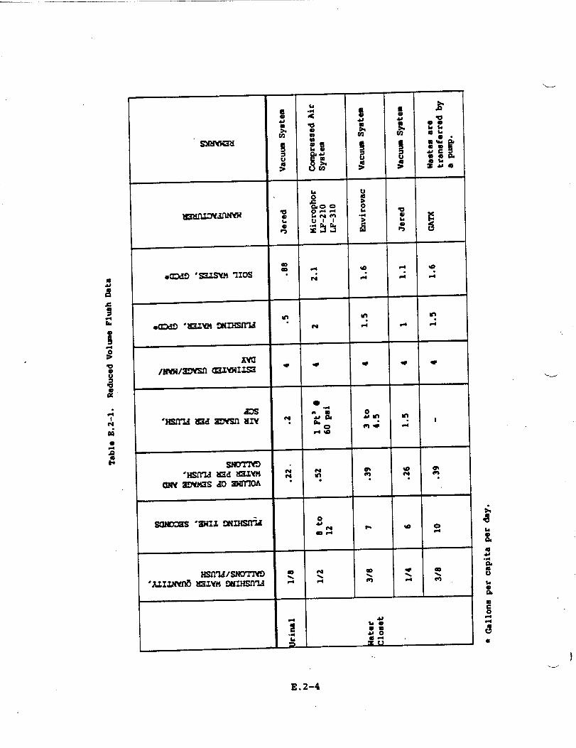
-----
I
t
t
t====
t
1
1,
I
I
8
J-
E.2-4
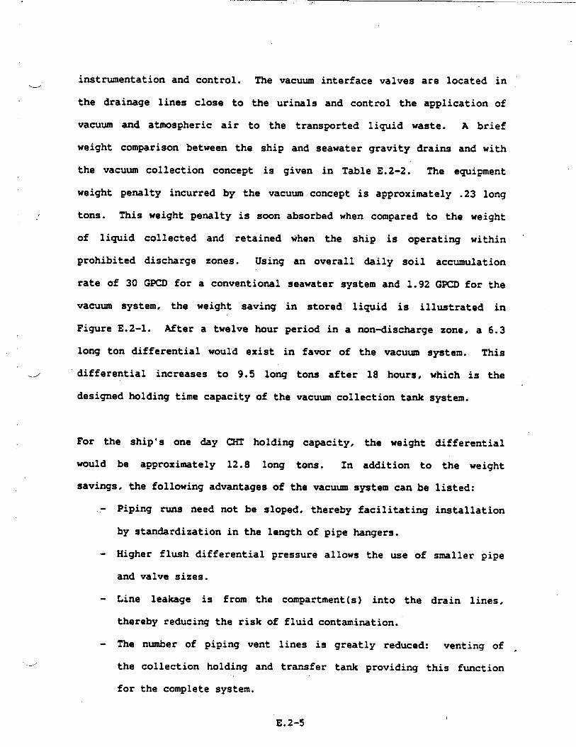
.,,:
instrumentation and control. The vacuum interface valves are located inw
_.
-J
the drainage lines close to the urinals and control the application of
vacuum and atmospheric air to the transported liquid waste. A brief
weight comparison between the ship and seawater gravity drains and with
the vacuum collection concept is given in Table E.2-2. The equipment
weight penalty incurred by the vacuum concept is approximately .23 long
tons. This weight penalty is soon absorbed when compared to the weight
of liquid collected and retained when the ship is operating within “
prohibited discharge zones. Using an overall daily soil accumulation
rate of 30 GPCD for a conventional seawater system and 1.92 GPCD for the
vacuum system, the weight saving in stored liquid is illustrated in
Figure E.2-1. After a twelve hour period in a non-discharge zone, a 6.3
long ton differential would exist in favor of the vacuum system. This
differential increases to 9.5 long tons after 18 hours, which is the
designed holding time capacity of the vacuum collection tank system.
For the ship’s one day CHT holding capacity. the weight differential
would be approximately 12.8 long tons. In addition to the weight
savings, the following advantages of the vacuum system can be listed:
.- Piping runs need not be sloped, thereby facilitating installation
by standardization in the length of pipe hangers.
- Higher flush differential pressure allows the use of smaller pipe
and valve sizes.
- Line leakage is from the compartment(s) into the drain lines,
thereby reducing the risk of fluid contamination.
- The number of piping vent lines is greatly reduced: venting of -
the collection holding and transfer tank providing this function
for the complete system.
IE.2-5

Table E.2-2. Plumbing Drainage Equipment Weight Comparison
r
STANDARD SYST~
ccMPoNEm
I---
---,
---
Standard vitreouschina fixtures
Iinferential weightenalty for largeriping sizes due toloping requirement
Ient pipinginferential weight“ncluding hangers,tc.
I Total Weight
1
LBs
14 @ 75= 1050
Est. @ 200
Est. @ 150
1400
VACUUM SYSTEM
CCUWNENT I ms,
Vacuum pumps, comletewith motor, tanks,valves
Vacuum collectiontanks, (135 9al. eachwith 10 gal. lowlevel liquid)
Vacuum interfacevalves
Lightweight fixturescomplete withvalves (1)
---
---
Total Weight
(1) Based on Jered, Inc. Model AVT 300
! @ 425 = 850;SeeAppendix B)
1(175+1OX8.34)= 517
[SeeAppendix B)
3@10=80
14 @ 33 = 462
1909
E.2-6
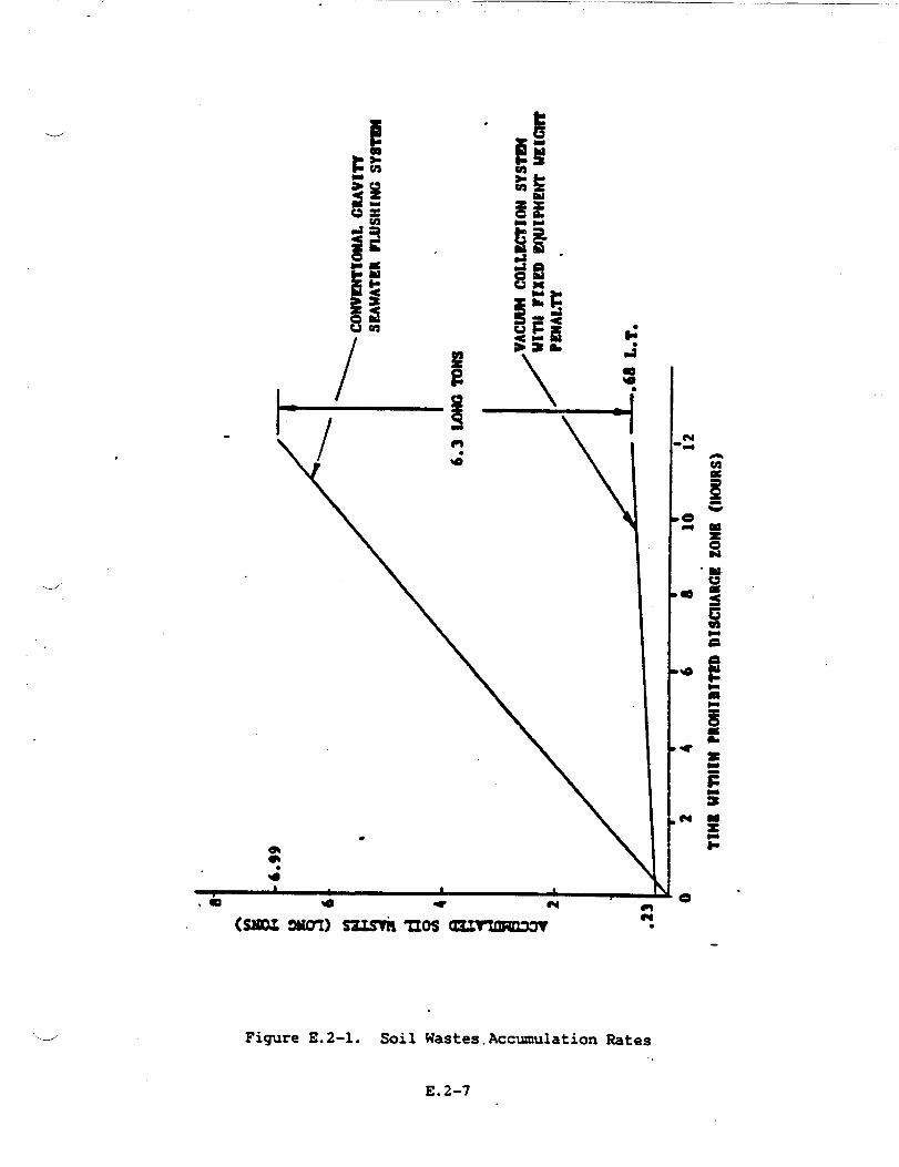
.
._/’
.
\
w—.
m4“ \’ I
0
mz0N
ti●
Figure E.2-1. Soil Wastes.Accumulation Rates
.
E.2-7

Sewage treatment equipment was investigated in an attempt to further
reduce the collection and holding tank capacity. However, it was
concluded that the weight penalty of approxi=tely 1500 pounds and
increased electrical load of approximately 25 b precluded such
installation.
DRAINAGE
PLUMBING
Plumbing
sanitary
SYSTEM DESCRIPTION AND
DRAINAGE
.
CHARACTERISTICS
drains are separated into
drains (ss Figure E.2-2).
SOIL DRAINAGE
two distinct systems; soil drains and
The soil drain system transports wastes of human origin
the water closets and urinals, both being supplied with
u
emanating from
sea water for
flushing. The soil drainage system is divided into tm subsystems, a
fonard and an aft. Drains from the urinals and water closets of the
fozward system are combined in a header below the second deck and are
collected into a 1850 gallon collection tank. Similarly, drains from the
urinals and water closets of the aft system are collected by a 1850
gallon tank.
SANITARY DRAINAGE
Drains from lavatories, sink, showers, la~dry =chines, commissary -)
equipment (including the garbage grinder) and deck drains from the galley
E.2-8

!s\—E
Id
0El
E.2-9
and the scullery are transported by the sanitary waste drainage system.
This gravity system consists of two sub-systems, one foward and one aft.
Waste drains from the vegetable
tables, kettles, ice machines,
discharged through an air gap to
peeler, dishwasher, refrigerators, steam
commissary sideboards and dressers are
the drain system.
The drain piping, mde of GRp material,.is pitched a minimum of 0.23 inch
per foot.
Drains from the medical treatment room are led independently to the
forward (XT.
Piping penetrating watertight transverse bulkheads utilize motor driven
full ported ball valves. These can be operated manually, or can be
controlled electrically
SCUPPER AND D= DRAINS
at the -.
These drains are grouped as
subdivision transverse bulkheads
much as possible between watertight
and led overboard via scupper valves.
Valves below the damage control deck are of the gag-type and can be
remotely operated from the second deck via reach rods. Piping material
is aluminum. Overtiard discharges are fitted with hose connections to
permit attachment of portable
from the helicopter hangar is
trunked for fire protection.
CRES.
w’
submersible pump discharges. Drain piping
independently led directly overboard and is
The. piping rmterial for these drains is
E.2-10

..——
e
.--’ OILY WASTE COLLECTION
The oily waste collection system is shown in
from propulsion, lift, gas turbine engines
collected by gravity. This piping leads to
directly to the
machinery Rooms,
local tank is a
Figure E.2-3. Waste
and diesel generators
four 5 gallon tanks,
oi1
is
or
main waste oil drain tank located below the auxiliary
and electrical generator Rooms. Associated with each
level control and pump to transfer the oil to the main
waste oil drain tank.
MAIN AND SECONDARY DRAINAGE
The location of the eductors, their size, function, seawater requirements
-/ and drainage characteristics of the main and secondary drainage are
summarized in Table E.2-3. Each element of this system is briefly
discussed in the following paragraphs.
PIAINDRAINAGE
The main drainage system comprising eight eductors, has the capability of
evacuating water from each of the main machinery spaces, combustion air
intake Rooms, the port and starboard propulsion engine
chambers, and auxiliary pump rooms, at a rate of not less than
Four of the eight
During the lower
eductors provide a two flow rate drainage
operating rate,. the ship seawater pumps
.suction from the sea. Each eductor serving a propeller room
air plenum
500 GPM.
capability.
are taking
is located
(in elevation) such that a suction lift of five feet of water or less
E.2-11

dw
4i
FigureE.2-3.
WasteOilDrainage
E.2-12
.-”’
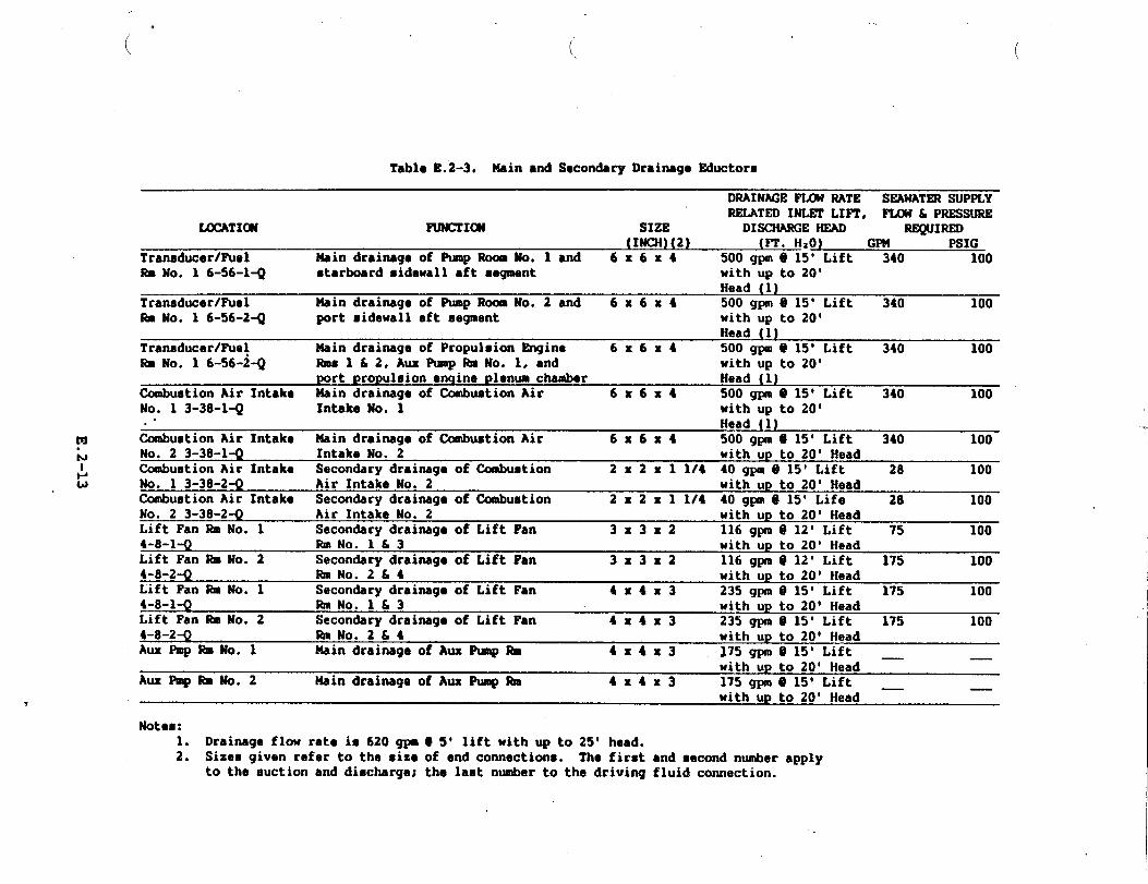
*
(
Tablo E.2-3. Ueh and Secondary Drahmg. Eductors
(
M“b
DRAINAGEFLCU RATE SEAWATERSUPPLYREMTED INLEfLIFT, FLOW & PRESSURE
LOCATI~ FUNCTION SIZE DISCHARGEHEAD REQUIRED(INCH)(2) (?-r.Hlo) GPM PSIG
Transducer/PUel Nain drainagaof Pump Room No. 1 ●nd 6x6x4 500 gpm e 15* Lift 340 100-No. 1 6-56-l-Q starboardsidewallaftsegment withup to 20’
Head (1)Transducer/Puel Nain drainageof Pump Room No. 2 and 6x6x4 500 gpn @ 15” Lift 340 100- No. 1 6-56-2-Q port sidewallaft segment with up to 20’
Head (1)Tranaducar/Pua~ Nain drainageof PropulsionEngine 6x6x4 500 gpm @ 15’ Lift 340 100~ No. 1 6-56-2Q Rmsl&2, AuxPumpRmNo. l,and with up to 20’
portpropulsion●ngineplenumchamber Head (1)(lxnbuationAir Intake Nain drainagaof CunbuationAir 6x6x4 500 gpm @ 15’ Lift 340 100No. 1 3-38-14 IntakeNo. 1 with up to 20’.’ Head (1)
Cuabustion Air Intake Main drainageof CcxnbuationAir 6x6x4 500 gpm @ 15’ Lift 340 100No. 2 3-38-1-Q IntakeNo. 2 with Up to 20’ HeadCambuationAir Intake Secon&ry drainagaof Combustion 2x2x11/4 40gpm@M’ Lift 28 100No. 1 3-38-2-Q Air IntakeNo. 2 with up to 20’ HeadCombustionAir Intake Secon&ry drainagaof Cunbuation 2x2x11/4 40gpm@15’ Life 28 100No. 2 3-38-2-Q Air IntakeNo. 2 with up to 20’ HeadLift Fan M No. 1 Secon&ry drainagaof Lift Fan 3x3x2 116 gpm @ 12’ Lift 75 1004-8-14 RrnNo.l!13 with-upto 20’ HeadLift Fan ibNo. 2 Secondarydrainageof Lift Fan 3x3x2 116 gpm~ 12’ Lift 175 1004-8-2+ lbnNo.2L4 with up to 20’ HeadLift Fan Rm No. 1 Secondarydrainagoof Lift Fan 4x4x3 235 gpm @ 15° Lift 175 1004-8-1-Q RmNo. l&3 with up to 20’ HeadLift Fan IbNo. 2 Secon&ry drainageof Lift Fan 4x4x3 235 gpm @ 15’ Lift 175 1004-8-2-Q RJnNo.2&4 with up to 20’ HeadAux Pmp RmNo.1 Main drainageof Aux Pmp RD 4x4x3 J75gpm@ 15’ Lift —
with up to 20’ Head —Aux Pmp SmNo.2 Nain drainagaof AM Pmp RIE 4x4x3 175 gpm @ 15’ Lift —
with up to 20’ Head —
Notes:1. Drainageflow rate is 620 gpm O 5’ liftwith up to 25’ head.2. Sizes given refer to the size
to the suction and discharga;of end connections.The firmtand eecondnumberthe laat numberto the drivingfluidconnection.
apply
,.
.>

exists at the
propeller rooms
of 10 psig.
eductor inlet, thereby providing a drainage rate for
of approximately 620 GPM, with a seawater supply pressurew
Similarly, the eductor located in each auxiliary pump
lower level will operate at submerged inlet conditions
room, being at a
thereby providing
a drainage rate in excess of 620 GPZ4 for the propulsion engine rooms
and/or the combustion air plenum.
By directing (valving) from the compartment to be drained, into the
suction of the seawater pump(s) and closing the no-l suction from the
sea. (boot strapping) the water evacuation rate from the compartment is
increased by 340 GPM.
SECONDARY DRAINAGE
The secondary drainage system has two, 50 GPM, 3 HP (60 Hz) positive
displacement pumps which permit collection of drainage into the waste
water tank, pumping directly overboard, or transfer from the tank to
shore facilities. These pumps are attached to a comon fore and aft
header. Branches from the header provide suction through motor operated
valves and check valves to drain wells.
monitored via level controls and are located
the propulsion engine rooms, the auxiliary
generator rooms, and the two lift fan engine
t~e
the
secon&ry drainage system (independent
lift fan rooms and in the combustion air
E.2-14
The wells are alarmed and
in the waterjet pump rooms,
machinery rooms, electrical
rooms. The six eductors of
of the pumps) are located in
intake {CAI).—,
The secondary eductor in each CAI is employed to remove small volumes ofu
water collected in the CM drainwell emanating from exhaust stacks and
demisters of the GTG(s), from rainwater and’light spray entering directly
through the CAI opening, and water from washdown of propulsion and lift
engine demisters. The larger, main drainage eductor located in each CAI
is employed during ship operation in higher sea states when greater flow
rates are incurred.
The two secondary drainage eductors located in the lift fan rooms serve
to remove water entering fan rooms through the lift air openings. Level
controls in the lift fan rooms control the operation of the smaller
eductor when dewatering rates of up to 33 GPM per fan are required, and
control the operation of the main drainage eductor, to complement the
first, to achieve a dewatering rate of up to 116 GPM per fan. This,_
higher rate is related to ship operation at -ximum fan speed, under
combined conditions of dense spray and heavy rain.
For
via
and
all eductors, actuation power is provided from the seawater system
motor operated valves, with watertight and explosion proof actuators
capable of local (manual) or remote (DCAEC) operation. Similarly,
there are xmtor operated valves for the eductor suction and discharge,
the latter two being combined with check valves. The check valve in the
eductor inlet line serves to protect against reverse flow of water into
the compartment from the actuation line caused by inadvertent or
accidental operation with a closed discharge valve.
.
d All eductors have a vacuum pressure gage installed on the suction side of
the eductor, and a pressure gage on the seawater supply side. A flow
E.2-15

switch is installed on the suction side for remote indication at thed
XAEC. Flow switches are also installed on the inlet side of both
secondary drainage pumps.
Normal control of the drainage system is at the =. where the
following functions are monitored:
a. Area flood warning (16), ‘
b. Eductor status ON/0~ (12),
c. Drainwell(s) high level alarm (18),
d. Pump status ON/OFF (2).
All secondary
DCAEC.
drainage pumps can be operated locally as well as via the
Sequencing of valve operation for operation of eductors
automatically, except that:
i) All six secondary drainage eductors are provided
control at the DCAEC allowing operator start/stop.
is controlled
with over-ride
ii) All main drainage eductors are supplied with seawater system
power only at the discretion and couunandof the DCAEC operator.
Operation of the secon&ry drainage eductors andlor pumps serving
c~partments which are also dewatered by -in drainage eductors is..
discontinued upon activation of the respective uain eductor level control -~
units.
E.2-16

Operation of secondary drainage pumps4
controlled, the demand signal coming from
week(s). Each has a low and a high level
and valves is automatically
level control located ub draub
triggering point, in addition
to its regular monitoring capability. Control is set-up to operate the
pump which is nearest the drainwell being served; should the flow rate
into the drainwell “exceed the outflow, the second level will demand the
start-up of the second pump.
Valves are normally controlled to discharge the waste water into the
waste water drain tank. An over-ride control at the DCAEC allows the
operator to divert the waste water directly overboard.
dockside, the wastewater drain tank is emptied
either pump (pump No. 1 on standby) after the
dockside discharge valve is manually opened.
A low level control within
closing of the tank drainage
the tank signals the
(three way ball) valve
During the tank drainage operation, any drainwell
to the shore facility
port or the starboard
stop of the pump and
(TDV).
demand will interrupt
the tank drainage by closing the TDV; the wastewater from the drainwell
than being directed to the shore facility.
Tank drainage mode is automatically resumed upon the removal of the
demand.
--
E.2-17

To prevent pump operation under cavitating conditions, a the~stat is
installed at the drainwells in the propulsion engine rooms which prevents
pump start-up until the water wash temperature in the drainwell cools to
at least 100”F.
-
1_.
E.2-18

APPENDIX E.3
HVAC SYSTEM DESIGN
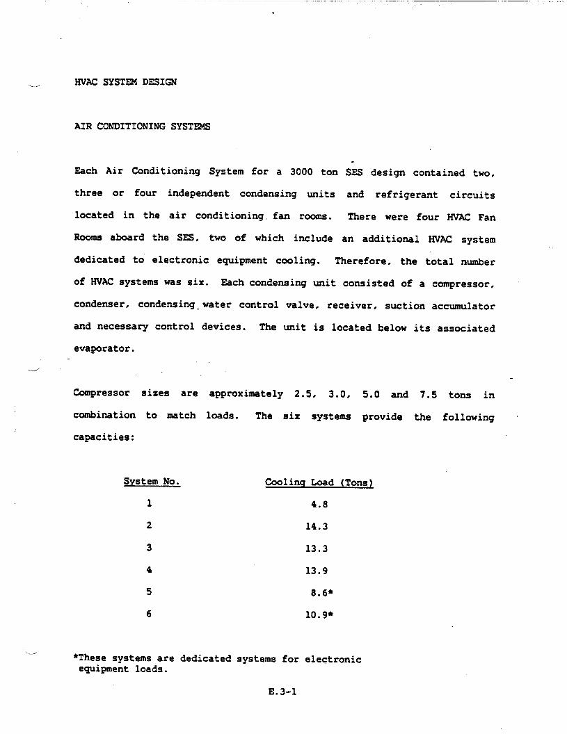
- .—
.
HVAC SYSTR4 DESIGN
AIR CONDITIONING SYST~
Each Air Conditioning System
.
for a 3000 ton SES design contained two,
three or four independent condensing units and refrigerant circuits
located in the air conditioning fan rooms. There were four HVAC Fan
Rooms aboard the SES, two of which include an additional HVAC system
dedicated to electronic equipment cooling. Therefore, the total number
of WAC systems was six. Each condensing unit consisted of a compressor,
condenser, condensing,water control valve, receiver, suction accumulator
and necessary
evaporator.
control devices. The unit is located below its associated
Compressor sizes are
combination to match
capacities:
System No.
1
2
3
4
5
6
approximately 2.5, 3.0, 5.0 and 7.5 tong in
loads. The six systems provide the following ~
Coding kad (Tons~
4.8
14.3
13.3
13.9
8,6*
10.9*
J●These systems are dedicated systems for electronicequipment loads.
E.3-1

CAPACITY CONTROL
Each air conditioning plant can be reduced in capacity by step sequencing
compressors within the plant. The logic for the step sequence will be
through control devices consisting of thermostats located within the
conditioned space and signal selectors, or
return ducts for equipment cooling,
Each control system consists of a number of
and a summary control to stage A/C compressor
The signal selector
each zone within a
thermostats located in the
zone monitors (thermostats)
operation.
will accept thermostat (voltage signal) output from
multizone system and
transmission to the relays controlling
signal will cause compressors to come on
to its voltage level.
select the highest voltage for
compressor staging. The high ‘.-.’
line or drop off in proportion
Within the controlled zone, the local thermostat will also cause
displacement of
proportional to
thermostat will
air distribution
the actuator for the variable air volume terminal
the themostat output. A final function of the zone
be to control the electric resistance heater within the
duct for that space. Each controlled zone will have one
variable air volume terminal and generally an electric resistance.
heater. The variable air volume terminal functions to control the amount
of conditioned
capacity based
the themostat
air serving a zone and thereby control the cooling
on load requirements. For equipment dedicated systems,
is located to sense return air temperature. A functional 1
block diagram for ?IVACcontrol is shown in Figure E.3-1. The concept of
E.3-2

.
TYPICAL ‘km
d“
-——— — -1—.-.————,—_ __S:’r&
.
ADDlT10xU_ZON%5As SPSCIFIEB
●
——
-.
.
Figure E.3-1. Functional Block Diagram for HVAC Control System
E.3-3
h

compressor staging with reference to zone temperature is shown in
Figure E.3-2. +
AIR DISTRIBUTION
A high pressure fan is located in each air conditioning plant fan room.
The fan draws a mixture of replenishment and return air from the fan room
and forces it through a filter and cooling coil into high velocity (2000
- 4000 feet per minute) ducting. In systems which are not equipment
dedicated, variable air volume terminals in each space admit only the
quantity of air necessary to cad the space to between 75*F and
So”r. The thermostatically controlled terminal has a preset maximum
and minimum flow rate. Minimum flow as approximately 50% of maximum
flow. Highly loaded electrical equipment spaces may be further reduced
to less than 50% to reduce reheat requirements. In”addition to cooling ‘- ‘“
flow control, the terminal contains noise absorption materials to
minimize air velocity noise. An induction feature of terminals serving ~
occupied spaces causes secondary induction of space air through the
terminal when primary air is reduced, thus maintaining nearly constant
air flow through the heater and diffuser.
Return air travels back to the fan room through passages, and in some
cases, is fan forced. Some of the air is expelled by exhaust fans
located in water closet spaces and other designated exhaust spaces.
Replenishment air from the 01 level is fed from the ventilation system to
the fan rooms. The replenishment air rate is reduced in one step to 50%
in the heating season to conserve electrical power.
E.3-4
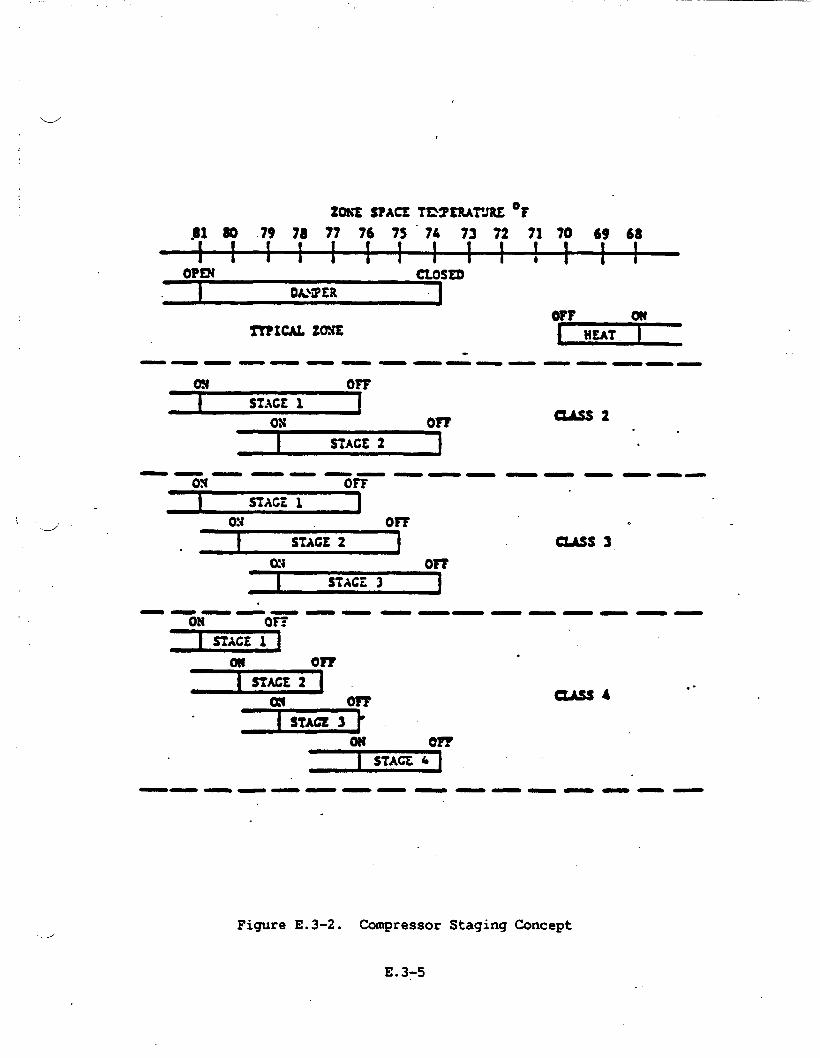
‘.-J’
1
\ ‘-d’
ZOh% SPACE TE2SMFJRZ ‘F
,S1 60 79 78 77 76 7S 74 73 72 71 70 69 68
1 1 i i I i 1 J I t b 1 i JoPna CLOSED
on~ICAL ZOXS
w
HEAT !
———— ——— ———— ———,— ——,
tM’F
I SIACE1 [ox or?
I STAGE 2
a&S2
.
——— ———— —— Ti OFF
———— ——
I STACZ 1 J0!{ o-
I STAGE 2. 1 UAss 3
.
‘2Eaiii!r– ”–—––––––m or?
.
i STACE 2 . .
1
———— ———— ———— ——
Figure E.3-2. Compressor Staging Concept
E.3-5
A relief or bypass damper located between the high pressure supply fan
inlet and outlet dumps air directly back to the fan room or return fan as
the terminals decrease air flow. This maintains relatively constant fan
flow to avoid instability of the fan which
design flow. The functional flow diagram for
in Figure E.3-3.
HEATING AND REHEATING
Electric duct heaters
zone. In some cases,
could occur at less than
WAC distribution is shown
are located in the supply air duct to each space or
a separate space or radiant heater is used.
V13UTILATIONSYSTEMS
Three supply fan rooms on the 01 level deliver from the weather, via
electric duct preheater, fresh air to ventilated compartments and fan
rooms of the air conditioning system.
Supply air to the medical spaces, pilot house and central control station .
include fumetight dampers in the ventilation supply ducts to preclude
possible
Mechanical
contamination from another space in case of cas~ltY.
and natural supplies are used to ventilate these spaces.
The propulsion and
the combustion air
lift engine rooms ventilation is
systems. The electrical generator
considered part of
rooms and auxiliary
machinery rooms are provided with mechanical SU@y and exhaust
ventilation systems. J
E.3-6

(
mLJA.
I
●
as Bm-mlMamt AM
-J

Electric radiant heaters and mechanical exhaust to the weather are
\&’provided for all sanitary spaces.
Ventilation air flow for non-air conditioned spaces is sized to keep
maximum summer compartment temperatures or rate of change in accordance
with the requirement of the Design Criteria Manual. ~n the winter, the
ventilation rate is reduced for energy conservation, by a single
themostat sensing weather ambient air.
HEATING OF =ILATED SPACES
Spaces
air is
.Swarme r
requiring preheated air have heaters in the air supply duct. This
thermostatically controlled at 45°F (average). Spaces requiring
temperatures are provided additional duct heaters, supplemented by
space heaters
thermostats.
~/
as necessary. These space heaters are controlled by space
GENERATOR COOLING
While normal ventilation is supplied to generator rooms. a secon&ry
source of air from the combustion air intake is applied directly to the
generator enclosures. The secon&ry exhaust air becomes warmer than the
primary exhaust air. Each is exhausted via separate fans. The enclosure
exhaust is exhausted up the stack while the room is vented by normal
exhaust.
i
E.3-8

,,.
SMOKE PROPAGATIONv
In the preparation of this study, the paramount hazard related to smoke
propagation has been considered:
The propagation of smoke and possible failure of ventilation control
aboard SES maY lead to the reduction of or inability to fight the
originating fire hazard. Limited visibility and the physical effect of
smoke inhalation will seriously hamper or negate conventional
fighting techniques. As such, this study has identified means of
and fire extinguishant containment.
The application of dampers
requirements set forth inu
as recommended in
the “Ship System
‘“e
fire
smoke
this study satisfies the
Specification, T22000001C,
Para. 3.2.2.7 in regards to a method of counteracting the effects of
smoke and toxic fumes. It further fulfills the requirements of the means
of such protection by planning restrictions on the ventilation system of
the SES.
SAFETY REC~ATIONS
1. Xnstall dampers in ducts to machinery spaces.
2. All dampers installed serving a machinery space or a space from
which machinery draws air must be provided with an interlock to
insure that the damper cannot be closed until machinery in the
space has ceased to operate.
E.3-9,
3. Under current design, the SES was not provided with an automaticu<
back-up fire extinguishing system. The incorporation of the
smoke dampers specified in this study is a provision which,
through the containment of smoke, or at least delay in smoke
propagation, allows conventional fire-fighting techniques to be
used as rapidly as persomel and equipment can be moved.
4. The build-up of residual heat in the Turbine Spaces
shut-off of the cooling fans is still being evaluated.
following
Until the
impact and amount of such residual heat is accurately determined
to be structurally safe it should be remembered that the use of
Halon as an extinguishing agent may be ineffective.
5. Should such be the case, an alternate, remotely
extinguishing system should be considered. A
actuated-. e’
technique
identified in Amphibious Assault Landing Craft Technology report,
dated Sep 1978, recoimnendsthe use of pressurized (400 psi) water
discharged as a mist. Test results indicated that a 9 ftz pan
fire was extinguished in 4 seconds with a discharge of 2 quarts
of water in a 500 cu. ft. volume space.
6. Where dampers are recommended but cannot be installed due to
weight or space considerations, the space served should be
provided with Halon flooding
rate of Halon to compensate
through doors and ducts..
and. ideally, an additional bleed
for loss of fire extinguishant
).-/
E.3-10
. . .. . ..
7.
d
a.
9.
Where grills or louvered vents are placed in doors or bulkheads
serving spaces for which dampers are recommended, the trills or.
vents should be provided with a manual closing operation that can
be controlled from either side of the grill or vents.
Where a smoke damper requirement is satisfied by a watertight
closure, the closure’s mode of operation
recommended for a smoke damper at that location.
should be that
Fume-tight dampers should be manually operated.and located, as
far as is practicable, inunediately outside the space seined.
Dampers should be secured open and so tagged under normal
conditions.
.
4 Tradeoff studies conducted during the U.S. 2K and 3KSES programs -
identified some promising subsystem design options and components as
follows:
A coamnercial 60 Hz vane compressor is now being manufactured by the
Fedders Compressor Company. The compressor is considerably lighter than
the Carrier Compressor that had been tentatively selected for SES. Vane
compressors are not internally vibration isolated like reciprocating
compressors. The latter are not suitable in applications where external
vibration or shocks are applied because excitation of the compressor
motor to the limits of the internal springs ultimately results in fatigue
-
E.3-11

cracking of the tubing connecting the compressor to the outside housing.
Only specially modified
could be used, with a
currently being used
Cincinnati is currently
compressors like the Carrier military compressor
resultant high cost. The vane compressor
in mobile applications. Welco Industries
testing 400 Hz modified vane compressors,
is
of
but
they are not as yet being marketed. The problem is higher rpm and life.
When available, these compressors should be considered. Also, the light
weight but expensive Fairchild Stratos screw compressor should be
considered.
LIGHT WEIGHT DUCTING
A major consideration in the initial design of the SES was to decrease
weight wherever possible.
One area where weight
weight, high-pressure
standard fans.
was saved on the HVAC system was the use of light
aircraft fans rather than the much heavier Navy
Weight-saving considerations were not fully explored for duct material
specifications. The initial HVAC design used the General Specifications
for Ships of the United States Navy. This general specification gives
the minimum thicknesses listed in Figure E.3-4.
These material thicknesses are for use on all surface ships. However,
most surface ship designs are not faced with the same weight saving
considerations as SES.\---i
E.3-12

Sheet for Fabricated Ductwork
.--”Nonwatertight Watertight
Diameter or Galvanized Aluminum Galvanized Aluminumlonger sides Steel (Inch) (Inch) Steel (Inch) (Inch)(Inches)
.
up to 6 .018 .025 ● 075 .1066.5 to 12 .030 .040 ● 100 .14012.5 to 18 .035 .050 .118 .16018.5 to 30 .048 .060 .118 .160above 30 .060 .080 .118 .160
Welded or Seamless Tubing
Nonwatertight Watertight
Tubing Size Aluminum Aluminum ‘(Inches) (Inch) (Inch)
2t06 .035 - .1066.5 to 12 .050 .140
Sprially Round Duct (Nonwatertight)
I
Diameter Steel Aluminum(Inches) (Inch) (Inch)
I upto 8 .018 .025Over 8 .030 .032
Figure E.3-4
E.3-13

In an effort to find an alternative to these specifications, the HVAC
design section investigated other types of ductwork for applicability toL/2
SES. One promising ductwork system is produced by United Sheet Metal of
Westerville, Ohio. They are specialists in spiral duct and have provided
ductwork for many U.S.
A new development at
section. ,It involved
around the spiral
shipbuilders.
United Sheet
a new process
ductwork.
representative, the added strength
Metal was of interest to the HVAC
that formed a continuous raised ridge
According to the United sales
of this ridge allows the use of
lighter weight duct. For example, if .060 aluminum ductwork is required
in a certain situation, a .050 raised ridge
strength at a weight savings of .183 lbs. per
Another opportunity
ridge flat oval
Previously, marine
for weight savings would
duct would provide the same
square foot.
be the use of spiral raised ‘-w’
ductwork in place of standard rectangular duct.
spiral ductwork was limited to round use only. The ~
new process at United would almost eliminate the need for rectangular
duct..
It should be pointed out that spiral duct is available for straight runs
only. Fittings are only available in standard weldable thicknesses.
Also, before the raised ridge duct is specified for any shipboard use,
test results must be obtained to verify that a lighter weight duct could
withstand the loads placed on it in high-pressure installations. “
‘d )
E.3-14
d Should the strength tests prove favorable, the use of this type of
ductwork would appreciably reduce the overall weight for the entire ship.
SMOKE PROPAGATION
The propagation and dispersal of smoke and noxious gases must be included
during the ventilation design phase. Final recommendations included:
a) Installing smoke dampers with interlocks in ducts to machinery
spaces;
b) Adding manual closing operations for louvers in doors and.
bulkheads.
‘v ‘Since smoke propagation and halon containment are a real concern,
recousnen&tions must be made prior to ventilation system design and
analysis.
By breaking up these ventilation syst~ into s~ller sYstem with
separate fans. crohs-comections can be eliminated. This will
chance of smoke or halon infiltration into manner spaces
shipboard fire.
MIL-STD-1472B offers much broader temperature and humidity
comfort zones and provides a more realistic approach
shipboard conditions. The summer comfort zone temperature
to 89 degrees and humidity ranges-from 10 to 90 percent,
reduce the
during a
ranges for its
to military
ranges from 67
. The winter
.
-’comfort zone temperature ranges from 66 to 83 degrees and humidity ranges
from 10 to 90 percent.
E.3-15
The boun&ries for the MIL-STD-1472B comfort zones are based on an
‘w’effective temperature (ET) scale, which shows constant physical sensation
lines. These lines give the combination of temperature and humidity
which provide the same comfort.
ASHRAE also has developed an effective temperature scale which varies
from the MIL-STD-1472B scale. Refer to ASHRAE Fundamentals Book for
further information.
-ERATURE REQUIREMENTS
The temperature requirements for air conditioned personnel spaces
(offices, berthing, wardrooms, etc.) in sumner was 80 degrees F dry
bulb/55 ‘degrees relative humidity, and in winter was 70 degrees F dryU’
bulb/no R.H. requirement. These were the standards from which the HVAC “-
calculations were developed. If it was possible to use more realistic
requirements,
appreciably.
equipment with
HEATING SEASON
The original U.S.
on surface ships
the heating and cooling loads might be reduced “
The lower loads would allow for smaller or less HVAC
a considerable.conservation of energy and wright.
Navy temperature
was 65 degrees F
requirement for
dry bulb. That
air conditioned spaces
temperature was raised
to 70 degrees in OPNAVINST 9330.7A, U.S. Navy Shipboard Habitability
Design Stan&rd. This stantird also includes the provision that.
appropriate tradeoffs be conducted to derive habitability features most‘.-.-)
responsive to mission requirements.
E.3-16 ,

.
In the case of the SES. a tradeoff study
dwhether lowering the design temperature in
F dry bulb will have an effect on
t
should be made
berthing spaces
reducing the
requirements. The lower design temperature
comfortable for sleeping, since metabolism for
half that of light office work.
to determine
to 65 degrees
heating load
would probably be more
sleeping is approximately
Making a rough preliminary estimate, it was determined that lowering the
design temperature of berthing spaces from 70 to 65 degrees would reduce
the KW required for
considerable savings
many heaters, thereby
heating those spaces by approximately 10 percent, a
of energy. This savings would reduce the size of
saving weight.
-COOLING SEASON‘d
?
The cooling season requirements for most air conditioning s~ces
(offices, berthing, etc.) on the SES is 80 degrees D.B./S5 percent R.H.
This design temperature condition, when plotted on the cooling season
psych chart gives
below the 75 degree
To analyze the air
an effective temperature reading of 74 degrees ET.
ET upper boundary of the summer comfort zone.
conditioning systems, each system room mix temperature
and relative humidity could be plotted on the psych chart to determine
the effective temperature for the system. The results of this analysis
are as follows:.
d
E.3-17
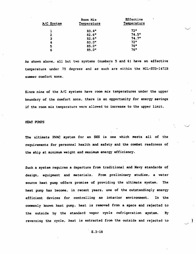
Room MixA/C System Temperature
Effective ‘Temperature
1 80.4°2 82.6°3 82.6°4 80.0°5 85.0°6 85.0°
72°74.5°74.7°72°76”76°
AS shown above, all but two systems (n~ers 5 and 6) have an effectives
temperature under 75 degrees and as such are within the MIL-STD-1472B
sumer comfort zone.
Since nine of the AiC systems have room mix temperatures under the upper
boun&ry of the comfort zone, there is an opportunity for energy savings
if the room mix temperature were allowed to increase to the upper limit.
HEAT PUMPS\-.,
The ultimate HVAC system
requirements for personnel
the ship at minimum weight
for an SES is one which meets all of the
health and safety and the combat readiness of
and maximum energy efficiency.
Such a system requires a departure from traditional and Navy standards of
design, equipment and materials. From preliminary studies, a water
source heat pump offers promise of providing the ultimate system. The
heat pump has become, in recent years, one of the outstandingly energy
efficient devices for controlling an interior environment. In the
comonly known heat pump, heat is removed from a space and rejected to
the outside by the standard vapor cycle refrigeration system. By
reversing the cycle. heat is extracted from the outside and rejected to )
E.3-18
the space. In the water source heat pump, the outside is replaced by ad
circulating water supply which serves as a rejection medium or the source
of heat, depending on the mode of operation of the heat pump. The
circulating water system is provided with means for cooling or.heating as
required to maintain the circulating temperature within limits which will
produce efficient space heating and cooling.
Customarily, heat pumps are applied to a complex structure in small
unitary -chines served by a single water system. It can be seen that by
this means heat can be removed from one portion of a structure and added
to another part if required.
For the SES, as applied to
‘compartmentation. individual..#
other structure
heat pump units
of similar complexity and
would be installed within
the space being controlled and would require little or no
exception might be a series of contiguous spaces, such as
having similar environmental requirements, where one heat
several spaces with interconnecting ducts.
duct work. h
berthing areas
P- may serve
The advantages offered by this system is weight, efficiency and space
saving are as follows:
1. The duct work
80%, partially
required may be reduced in weight by as much as
by reduced size and primarily by elimination.
2. The weight and complexity of electric duct heaters is eliminated
entirely along with the wiring and controls..
E.3-19

3.
4.
5.
6.
7.
8.
9.
10.
Electrical load is drastically reduced for heating since heat
pumps provide approximately three times the heat of resistance
heaters per watt.
Fuel consumption for electric generation is reduced.
Waster heat from the exhaust of the electric generators is added
to the circulating water system to provide space heating.
Simultaneous heating and cooling of any space is eliminated
saving energy and fuel.
Fan rooms for HVAC are eliminated.
Controls become simple heating/cooling the-stats. reducing
system complexity.
Reliability is enhanced since each heat pump is an individual
system. The failure of a heat pump will only affect the area
served and not affect the operation of the balances of the system.--
Infinite zoning is possible for special temperature requirements.
The disadvantages are:
1. Additional ventilation ducting would be required since
replenishment air must be piped to each heat pump. However. these
are small ducts and do not add significantly to the system weight.
2. Piping would be increased by the circulating system. Such pipes
are light weight fiberglass and do not require insulation.
3. A means of heat rejection and a waste heat boiler would be
required adding to system weight.
“i._.’
4. Condensate drainage problems ~uld be c~licated by the n~er
and dispersion of the evaporators. .J
E.3-20
Water source heatu
available from a
pumps have been marketed for over 20 years, and are
number of suppliers. However, no information is
available as to their compatibility with the marine environment.
PROPULSION _UST DUCTS
In the current ship
are located in the
configuration, the outboard propulsion exhaust ducts
upper level of the 2and deck aft, both port and .
starboard. The extremely high temperatures in the exhaust ducts require
that the pump rooms each have their ‘ownventilation system.
The solution to this design problem is to locate the propulsion exhaust
ducts outside the watertight boundary of the ship,
‘watertight deck directly under the exhaustd
and providing grating above and outboard of
ducts at the
the ducts.
by locating a
2and deck level,..
,
The propulsion
air, and would
exhaust ducts
not require a
would then be cooled by exposure to outside
separate ventilation system.
The drawback of this proposed solution is that a sizeable portion of the
flight deck would be made of some type of grating, with reduced
structural strength. A structural analysis would be required to
determine whether additional structural members were necessary..
VORTEC COOLING SYST~ .
.
In reviewing the problem of backup cooling for vital equipment, the.
d
VORTEC cooling system was ‘investigated.
E.3-21

The VORTEC enclosure cooling system
Cincinnati is a product which converts
one hot and one cold. The cold air
sold by VORTEC Corporation of
wcompressed air into two streams,
is directed into the electrical
enclosures, replacing the heated enclosure air which is induced and
vented outside with the hot exhaust of the vortex tube. The product can
be used continuously, or with a thermostat
The entire cooling system uses 25 CFM
for intermittent usage.
at 100 psi inlet pressure.
Refrigeration 1s generated at the rate of 1500 BTU/Hr or 440 watts when
running continuously.
As can be seen from the above f@ures, these
partial solution to equipment
backup system in the event
cooling for the A/C system.
As stated above, this system
lines. Also a route must be
the outside.
cooling. However,
products offer only a
they might be used as a
of A/C system’ failure, or as preliminary.- W
requires connection to
found for the exhaust
the ship senice air
from this system to
E.3-22

.-———
APPENDIX E.4
FRESH WATER SYSTEMS
w
.-/’

For the distillation plant, three options were considered:d
a. An electrically heated vacuum distiller
b. A vacuum
heat,
c. A reverse
The electronics
distiller which used the turbine engine exhaust waste
osmosis process
cooling,. ~table and fresh water and auxiliary fresh
t!
water cooling systems adhere
alternatives were considers;
primarily to offer a weight or
to stan&rd Navy practice and no system
however, some variations were considered
water savings. As an example, Table E.4-1
outlines
1.75 GPM
.4
several showerhead options. The Low Flow Showerhead which uses
was selected for the system.
.
The results of trade-off studies performed in the distiller area have
lead to selection of a commercial, electrically heated, vacuum
distillation unit. The reverse osmosis unit, even though advances have
been made in membranes suitable for sea water use, was eliminated because
no commercial unit specifically packaged for shipboard service was
available. This process, however offers long tern potential because of
modest installed weight and minimal operating power requirements.
Utilization of turbine exhaust waste heat was eliminated on the basis of
convenient packing of water heating coils around the GTG exhaust ducts.
and because of somewhat higher overall weight than the vacuum still.
.-/
E.4-1
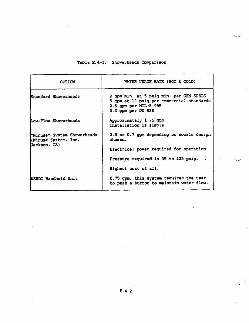
Table E.4-1. Showerheads Comparison
OPTION WATER USAGE RATE (HOT & COLD)
ltan&rd Showerheads 2 gpm min. at 5 psig min. per GEN SPECS5 gpm at 12 psig per commercial 8tandards2.5 gpmper MIL-S-9555.3 gpm per DD 938
OW-F1OW Showerheads Approximately 1.75 gpmInstallation is simple
Minuse” System Showerheads 0.5 or 0.7 gpm depending on nozzle designMinuse System, Inc. chosen.~ackson,CA)
Electrical power required for operation.
Pressure required is 35 to 125 psig. .
Highest cost of all.
lSRDCHandheld Unit 0.75 gpm, this system requires the userto push a button to maintain water flow.
)-2
E.4-2
,
DISTILLING PLANT.-.-”
The distillation units (2) selected are of the vapor compression type
(the--compression ). The units are self-contained “package type”. The
units are designed for automatic operation, and is suited to remote start
and monitoring.
Each unit will produce,
gallons per 24 hours of
will produce distillate
without descallng or cleaning, an average of 2400
operation over a period of 10 days. The plant
from sea water of not less than 1.32 density (32
pounds of sea water containing one point of dissolved salts) and at
temperatures between 28° and 85°F. The product water will have a
salinity
(ePm)‘or4
The unit
content not exceeding 0.0325 equivalent per million ‘ofchlorides
0.125 grains of sea salts per gallon (gpg).,,
operates on input power sources as follows:
a. 440 V, 3-phase, 400 Hz for all pump motors, electric heaters, and
compressor motors.
b. 28 V, direct current for control circuitry.
c. 110 V, l-phase, 400 Hz for operation of the salinity indicating
system.
The unit incorporates a suitable system for locally monitoring distillate
purity by means of a relay meter calibrated in microhms/cm, with
automatic correction to 77°F. The meter will provide
point relay contacts for local audible andd
contact rating for additional remote alarms
E.4-3
visual alarms
and controls.
adjustable set
with sufficient

,
The distillate will be disinfected by use of two in-line (one
distiller) proportioning brominators. Bromine concentration
for each
will be
maintained at the correct level by an off-line, manually operated,
recirculating brominator in the potable water storage portion
system.
The materials of construction conform to U.S. MIL-D-16196D
Class A, for those surfaces in contact with the process fluids.
interest of weight reduction, aluminum alloys will be used
of the
(Ships)
In the
in the
fabrication of the mounting skid, pipe supports and brackets. Suitable
design precautions will be observed for the prevention of galvanic
corrosion.
POTABLE MD
The potable
Figure E.4-I depicts
FRESH WATER sysm14S
the distillation plant diagrammatically.
.- ‘.-J’
and fresh water service system is designed for continuous
duty with suitable redundancy or duality in major equipment items. The
system design is in general compliance with General Specifications, but
contains some modifications designed to tailor the system to the
specified needs for the SES. Hot and cold water is furnished to the
ships fixtures in accordance with the GSS. The fixtures
service outlets requiring hot and cold potable water
Table E.4-2.
Recirculation loops
that hot water is
for the fore and aft portions of the
provided within 15 secon& at any
and maintenance
are listed in
independed system provides pressurized. untreated water,
flows and temperatures to all of the ships turbine engines
E.4-4
system ensure
outlet. An
at specified )L/
for washing.

..
..
.——z
.-.--’
● Lr.
-J
.
FigureE.4-1.
DistillingPlantDiagram
E.4-5
.

TablaE.4-2. PotableWaterServicaconnections
&
FIXTUREOR INSTANTANEOUS PRESSUREAT suPPLYTmPSE31VICE(XJTLST m -MTE (GR4) FIXTURE(PSI) (‘F)
ShouorSink, ServicoSink,ScullqryLavatoryVeg. PeelerDishwasherHashingMachirmDrinkingFountainIceUachineIceCreamDispeneerSteamTabloGreaseInterceptModeWaterClosetsUrinalsHeloWaehOutletWindshieldWashDutletSteamGeneratorCarbonated Beverage DiepeneerCoffaeUrn/MakerSoosterHeatarLiftFan RoomOutletCombustionAir RoomOutletFilterCleaningHoodTraeh(hpactor RoamPropulsionRoomOutletPropulsorRoomOutletAuxiliaryMachineryRaomOutlet
125122112711361481“211314211224
1.7566331.8250.23*
105.43.53.5105335610107.9510105
101010101030
40/10010401060
40/803535305
20/503018015/45303030
40/8030303030
H&CH&c160SCH&C
c180H&cccc
70/225140/180
ccccHcHHcc
140/180cccc
(
,,
(.
..?, –.,4
.,.
Provision is
4 specified by
Figure E.4-2
made for proportioning detergents into the wash water, as
the turbine manufacturers.
illustrates the potable and fresh water service system.
ELECTRONIC COOLING WATER SYSTR4
The electronic cooling water system delivers 59°F fresh water to
electronic units. The system is comprised of standard package type water
chiller, with an electrically powered compressor and a sea water cooled
condenser. distribution piping {essentially ~), two pqs, flow
balancing valves,
instrumentation of
-depicts the systemId
expansion tank and pressure, temperature and flow
both local and
schematically.
remote indication type. Figure E.4-3
r
AUXILIARY FRESH WATER COOLING
The system design is based on the system described in Navy Mechanical
Standards Drawing No. 803-225-1137 entitled “Electronics Cooling Water
System”. A standby heat exchanger is not included in the system design.
The system, constructed essentially of CRES, provides demineralized water
at 105°F and the purity specified in MIL-STD-11399; which is a standard
governing cooling water to be used in support of electronic equipment..
The system is initially charged with water of this quality and is
maintained at this level of purity by a demineralize located in a bypass
loop of the system. The bypass loop is sized at 5 percent of the total.
system flow. Figure’E.44 depicts, schematically, the system elements.u
E.4-7
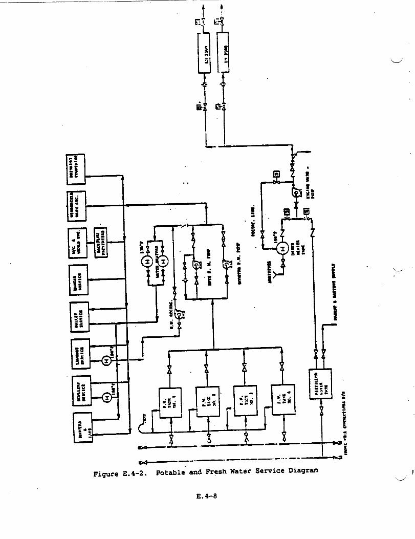
1i
&Tr
+
6?Eil“ r-?
Ii e
T.—
~—--— —
-.- —.- ,-- --
“
Figure E.4-2. Potable and Fresh Water Sewice Diagram
E.4-8
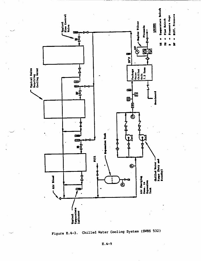
.
1
.
‘d .
.
/.
19
:.1
. \ 4
.
Fi~re E.4-3. Chilled Water Cooling System (SW’BS532)...4
E.4-9
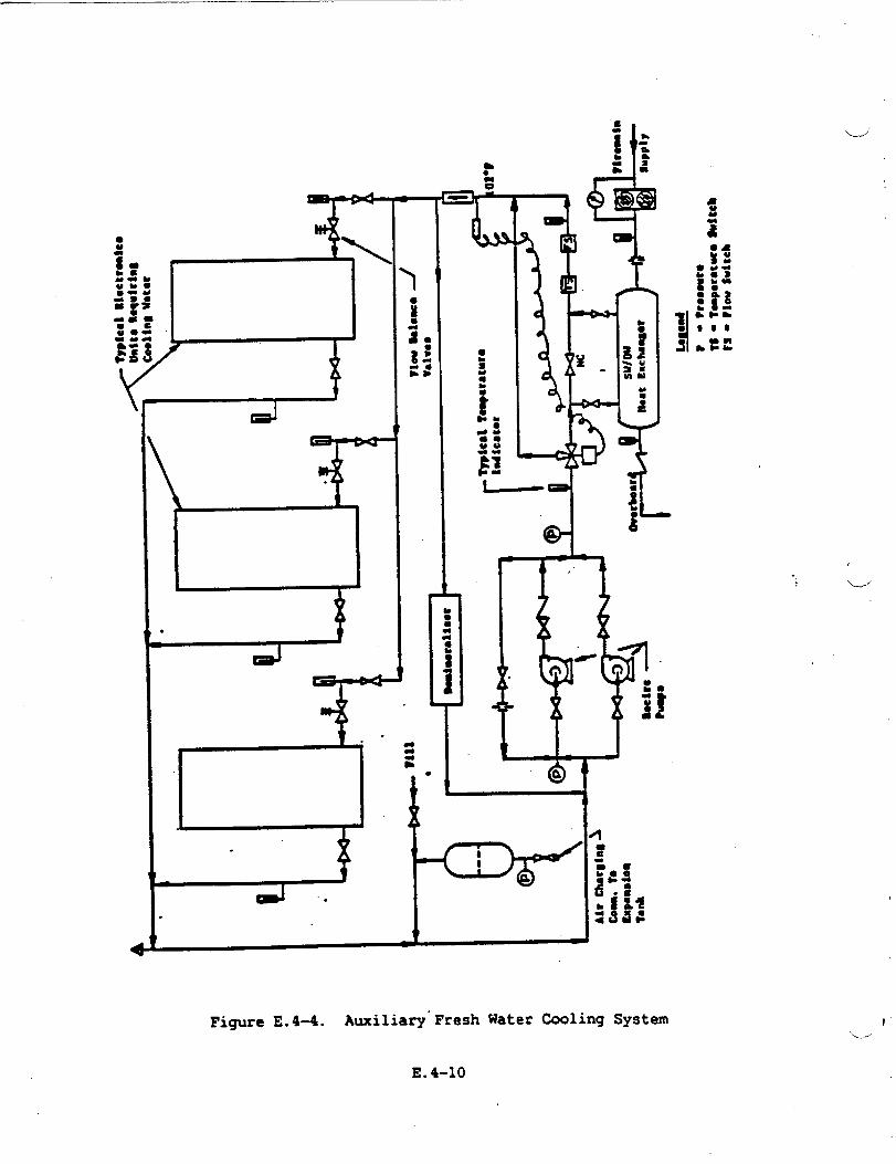
‘Ud
+
GA
.
●bao
T
--#R’
<
d
t 1
Figure E.4-4. Auxiliary”Fresh
E.4-10
Water tiling System
,
L“

,,,
d“
‘e -
APPENDIX E.5
PUEL SYSTEMS

.
FUEL OIL SYST~
J
The fuel oil system had three basic functions; service● transfer and
trim, and stripping. The service subsystem served the fuel demands of
the propulsion plant the lift system, the electric plant and also provide
“clean” fuel to the helicopter service tanks.
Table 2-10 provides a summary- of the Fuel Oil Service operating
parameters.
Table E.5-1. SES Fuel Oil Service System Requirements
a
Fuel
fiel Pressure
Fuel Temperature
Particle Size
Particle Quantity
Maximum Entrained Water
Content (per volume)
at 70°F
Maximum Flow Rate
(all services)
Black Ship Flow Rate
MIL-T-5624 (Grade UP-51
5 to 50 psig
15” almve cloud point to 150”F
10 u absolute “
10 mglgal
40 ppm
350 gpm
12 gpm (28 VDC Motor Driven Pump)
The SESd
Fuel was
Fuel Oil Service System originated at the ship’s service tank.
drawn from the fuel oil storage or fuel oil trimistorage tanks,
E.5-1 I
processed through a set of duplex filter separators and transferred to
the dedicated Fuel Oil Se-ice tanks. When the fuel oil is delivered to
these tanks, it is no longer available for trimming, thereby reducing air.
and water contamination. The fuel oil service subsystem took suction on
the service tanks,
fuel again before
engines. The Fuel
and a second set of
delivering it to the
Oil Service System is
filter separators processed the
propulsion. lift and electrical
divided into port and starboard
distribution systems. Each systein incorporated dedicated pumping,
filtering,
starboard
Components
● Two
● TWO
● Two
● Two
and flow control components. By cross-connecting the
and port systems, complete redundancy is afforded the SES.
included are:
service tti’s
service manifolds
prefilter-filterlseparators
sezwice pumps
● Vents and overflows
● Liquid level indicators
● Damage control valving
● F1OW control valves
The heart of the service system is its distribution center or fuel oil
service manifolds. The manifolds are designed to integrate into one
unit; a high flow (350 gpm) centrifugal aircraft p-, a low flow (12
gpm) centrifugal pump, and cartridge type isolation valves.
The high flow service pump is for normal
flow pump will be used for “start-up” and
E.5-2
operating conditions, the low 1w
black ship operation. The high
.
,..
flow service pump is driven by a 400 VAC - 30 - 60 Hz electric motor, the
dlow flow pump is powered by a 28 WC electric motor.
The concept behind -nifolding the service
weight, eliminate tubing joints, and provide a
The filter-separators conform to MIL-F-15618
components is to reduce
local center of control.
and are designed for 350
gpm, 10 u absolute particle size, and 40 ppm entrained HzO at 70°F.
The units are designed with a prefiltering stage to eliminate particulate
contamination at the filtering elements thus maintaining high performance
and long life.
The trim and transfer system receives the ship fuel from the refueling
-stations and distribute it to-d
trim/storage tanks. The system
manifolds, for trim and transfer.
psi. The transfer system supplies
the fuel oil storage and fuel oil
incorporates 2 pumping stations or
Each has a capacity of 350 gpm at 80
fuel to the service tank through a set
of duplex filter separators
system route fuel to and from
storage tanks, to adjtit the
operating profile.
similar to the service system. The trim
the trim/storage tanks, and if required the
craft center of gravity as required by the
The
the
was
The
transfer and trim manifolds were designed with
semice manifold, and incorporated similar
obtained by pairing the trim manifold with
distribution system was symmetrical about the
the same basic idea of
components. Redundancy
the transfer manifold.
centerline of the ship,.
thereby providing equal pressure drop and an even fueling rate duringu
E.5-3
refueling operations. The transfer and trim system consisted of the
following components:
Transfer System
● One
● One
● One
● One
fuel oil storage tank
transfer nanifolds
350 gpm, 80 psi. 440 VAC - 30 - 400 Hz centrifugal pump’
duplex filter/separators per MIL-F-15618
● Damage control valves
● Vents and overflows
● Liguid level indicators
Trim System
● Four trim-storage tanks
● One trim manifolds
● One 350 gpm, 80 psi, 440 VAC - 30-400 Hz, centrifugal pump
● Damage control valves
A stripping subsystem was incorporated into the overall fuel oil system
to remove water
processed to the.
transferred from
contamimtion. Contaminated fuel oil is collected
Contaminated Fuel TanJc (CFT). The contaminate is
the CIT to a dedicated contaminated fuel holding
and
then
tank
(CFHT), and retained here until discharge to a proper facility is
u“
available. The stripping system is independent of the fuel oil system
and served all fuel oil tanks..--”
E.5-4

.—
The stripping system consisted of:/
d
● Two stripping awmifolds
● Two centrifugal ZOO gpm, 50 psi, 400 VAC - 30 - 400 Hz
electric motor driven pumps
Refueling and defueling operations are performed at refueling at sea
stations (RAS). The fueling replenishment at sea equipment
located and installed in agreement with U.S. Navy Document
requirements of fuel replenishment at sea are defined as
replenishment, at a maximum of 3,000 gpm using U.S.
equipment.” The requirement of 3,000 gallons per minute
rate was satisfied through transfer stations (7” hose,
‘receiver) port and starboard. The receiving” stationJ
was designed,
NWP 38D. The
“side by side
Navy standard
replenishment
single proble
included the
required equipment to handle the 300 foot heavy weather rig. Dockside
fueling of the craft was performed through the same fueling equipment
used for underway fueling.
The design of the controls for the fuel system was based on a combination
of manual and automatic control. All valves were electrically (24VDC)
operated with manual redundancy and position indicators. The use of the
functional manifolds allows the controls to be set to any function
(alignment of the system) and powering the system to achieve
predetermined tank levels.
Fuel control functions were performed manually and electrically. At each
1 manifold, a centralized electric control station and a local control
station was provided. The display was: (a) digital and warning light for
E.5-5
the fuel level, (b)
(selector switch),
lights for pumps,
fuel temperature
indicator for fuel
and (g) readout for
digital and warning light
(c) warning lights for
filter, filter coalescer,
for the pressure indicators
filter P, (d) functional
(e) digital indicator for
at service tanks (selector switch), (f) digital
temperature at engine inlet (engine instrumentation).
strapped-on flow meter (selector switch).
Puel systems design integration was
where all the functions of the system
except the helicopter fueling functions
Through fuel management. the proper
represented by the central control
are monitored and all the functions
controlled for
central control
fuel management
the best attitude and
are controlled.
ship center
performance
together with the monitoring devices
possible.
AVIATION FUEL SYSTEMS (JP-5)
of gravity can be
of the craft. The
and in&ruments make‘.-J
The aviation fuel system (JP-5) was designed and engineered
with Section 542 of the GSS. The JP-5 Aviation Fuel System
service tanks is an independent system in its operation and
tanks are filled from the SES JP-5 service tanks
in accordance *
from the JP-5
control. The
through the
prefilter-filter/separator uriitsof the SES fuel system service subsystem..
The JP-5 system included a manifold that integrated the fuel pumps and
valves (identical to the one of the SES D~ Fuel Oil System), electric
motor operated valves, a filter/seParator# and a control station just VI
below main deck level that included the hose reel for inflight refueling
E.5-6

and connections
Since the pumping
pressure increase
for deck fueling, defueling and fuel recirculation.
equipment was of the centrifugal type, the differential
during inflight refueling reduced the flow capability
to 150 gpm.
NATERIALS
The Fuel Oil System on the SES has the advantage of being compatible with
existing aircraft materials and components. Except for the large size
components and filters, aircraft
potential.
Tubing is a corrosion resistant
4 ccmmonly known as 21-6-9 CRES or
strength alloy allowed the use of
reliability
safety. The
A survey of
improved the
resistance to
system
hardware was utilized to its maximum
steel of high strength per ANS 5561,
ARMCO Nitronic 40. This high tensile
thin wall tubing that together with the
installation with a large margin of
corrosion is compatible with-CRES 3161.
the market indicated that the fuel valves as used in aircraft
fuel systems were suitable and compatible with all the conditions. The
only modification required was the change of the aluminum alloy butterfly
disc to stainless steel to increase the pressure rating of the valves.
All valves incorporated thermal relief.
4“
E.5-7

.--’
APPENDIX E.6
COMPRESSED AIR AND NITROG~ SYSTEMS
‘../
d“
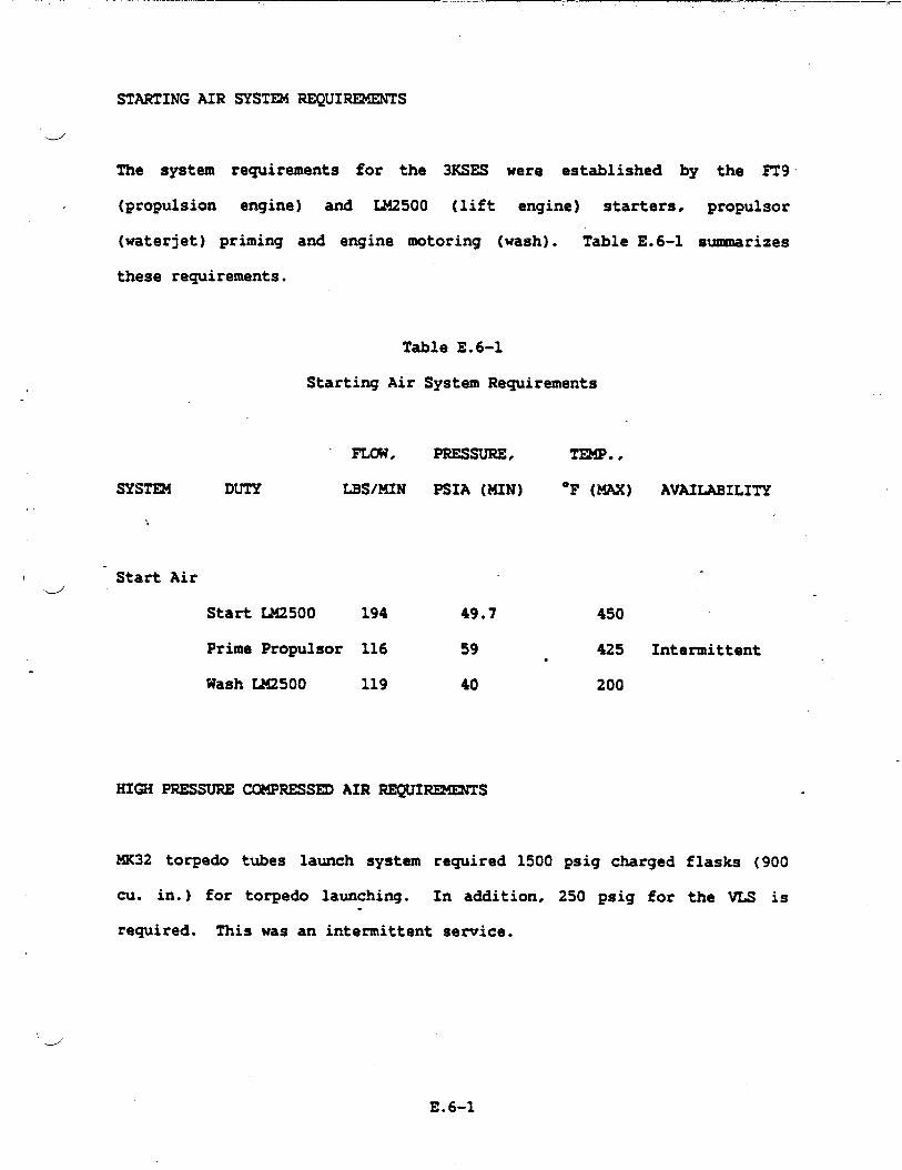
STARTING AIR SYS- REQUIREMENTS
J
The system requirements for the 3KSES were established by the ~9
(propulsion engine) and W2500 (lift engine) starters, propulsor
(waterjet) priming and engine motoring (wash). Table E.6-1 summarizes
these requirements.
Table E.6-1
Starting Air System Requirements
FLCm, PRESSURE, TEMP.,
SYslm! DUTY
->
MS/MIN PSIA (MIN) “F (MAX) AVAILABILITY
\ Start Aird
Start LM2500 194 49.7
Prime Propulsor 116 59
Wash IA42500 119 40
.
450
425 Intermittent●
200
HI@i PRESSURE COMPRESSED AIR REQUIREMENTS
MK32 torpedo tubes launch system required 1500 psig charged flasks (900
cu. in.) for torpedo launching. In addition, 250 psig for the VU is.
required. This was an intermittent service.
----’”
E.6-1

SERVICE AIR SYSTEM REQUIREMENTS
w“
The service air provided uninterrupted service to vital systems by the
use of a priority valve. Dry air was provided for wave guide
pressurization and other equipment as rewired. Regenerative type
desicant dehydrator was used to assure air quality per MIL-D-23523 for
Type 11 dehydrators. Outlets for non-vital services were fitted with
in-line filter, regulators and gauges as re~ired. Table E.6-2 provides
a summary of service air requirements.
NITROGEN SYSTEM REQUIREMINTS
Nitrogen Systdn
accordance with
provided oil-free nitrogen at 4 to 3000 psig in
Federal Specification BB-N411. . Type 1. Grade A, .
Class X. Distribution and outlet discharge pressures of nitrogen - “
stations satisfied those requirements of NAVAIR Bulletin lC to accomplish
certification.
Nitrogen System
SYST~ DESIGN
System denan~ for nitrogen is provided in Table E.6-3, “
Requirements.
The Start Air System is shown in Figure E.6-1. The source of start air
was three load compressors driven by 3 diesel generator sets. Each DGS
drove one load compressor as required. The load compressors could be
de-clutched when not required. One load compressor was capable of
starting one propulsion engine at a time or one lift engine at a time.
The propulsion engines could also be started by cross bleeding, one at a
E.6-2
w
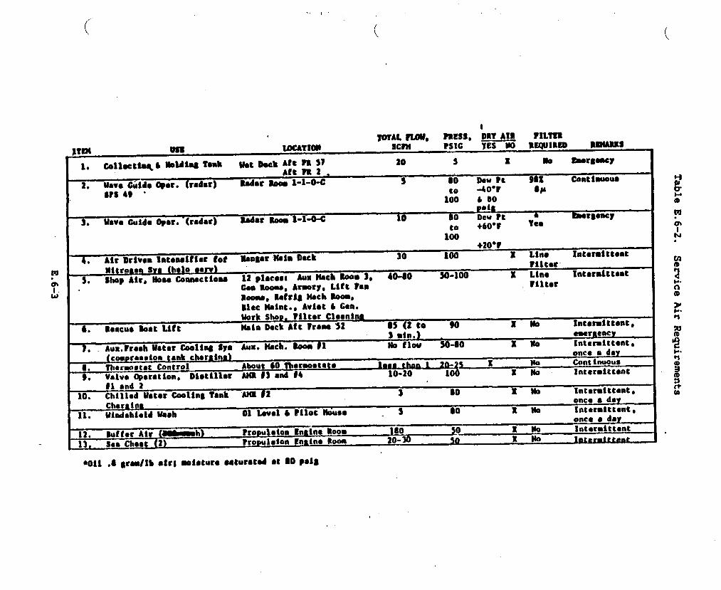
..
(... .
t?N!SS, DRY AIR?IWAL?UW ~~lc — ?lLm
ltm Vs8 WCA?lan Scr?t yes m RxqulRf!D mwxs
pottUav. Ouidc Opar. -(radar) Sadar xOo,l-l- 10 80 Dew Pt ● ~r$oncy
●
to +60”F Yes
--—+20V
Air Dtlvon Intensltier tot xeo#sr?MaDeek 30 100. x Ltno Int.rmittmt
)lltroaen SW9 halo ●orv} ?lltsr
5* Shop Air, HoaoCoaaactio- 12 placosl &x Heck Som 3, a-so 20-100 X Lin. Int.rmittcatOaauoou, Armory,LtCt ?an riltorBu, Rofris Mcb WxmBlec Neint.. Aviac L Cen.UorkShop. isltcr Clesnhm
6. RoacuoSoaturt lb~n DackAtt hm-’52 M (2 co 90 Iti Xnt.tmfltt.mto3 ●in.) rnraency
Aum?reeh Ihter Coollna Sya Aux. Uech. SoOa 11 w flou so-so x Ho Inter=ittcntt●
(coaprosslon tenk ehe rt ins) once a dey
8. Th.rmmtat Control About 60 nl@rBo6tats lQ2&LhmJ 2a-2s x WO Continuous
9. Valve @gration, Distlllar M ~~ ●nd #~ 10-20 100 EM Intermlttont
onc9 ● daq
12. Suffer Air (~h) tropuleioa Enatna Roo8 180 so XMO Intoraittmnt
13,

.
.
.
-.L/”
..
.
I
lb
FigureE
.6-1.StartAirSystem
E.
6-4
..
‘u
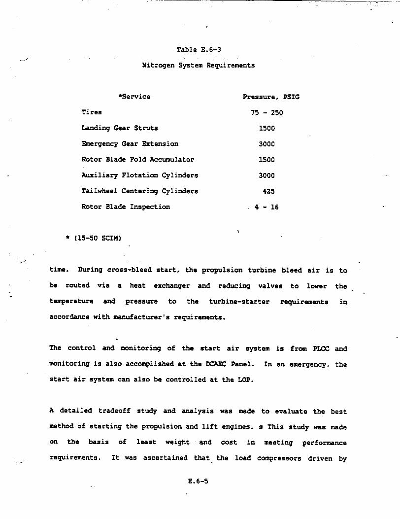
.
Table E.6-3
-/Nitrogen System Requirements
*Semite
Tires
Landing Gear Struts
~ergency Gear Extension
Rotor Blade Fold Accumulator
Auxiliary Flotation Cylinders
Tailwheel Centering Cylinders
Rotor Blade Inspection
* (15-50 SCIM)
Pressure, PSIG
75 - 250
1500
3000
1500
3000
425
4-16
time. During cross-bleed start, the propulsion turbine bleed air is to
be routed via a heat exchanger and reducing valves to lower the
temperature and pressure to the turbine-starter requirements in
accordance with nmwfacturer’s requirements.
.
The control and monitoring of the start air system is from ~ and
monitorincjis also accomplished at the XAEC Panel. In an emergency, the
start air system can also be controlled at the LOP.
A detailed tradeoff study and analysis was made to evaluate the best
method of starting the propulsion and lift engines. s This study was made
on the basis of least weight and cost in meeting performance
requirements. It was ascertained that the load compressors driven by—,
E.6-5

,diesel generator sets was the method to be adopted. A weight efficient
SES would delete existing cross-bleed due to triple starting redmdancy,
thereby reducing system weight and cost.
“L#’
The start air system as shown in Figure E.6-1 performs the following
functions:
o Start propulsion engines, one at a time, using air
compressor.
o Start lift fan engines, one at a
compressor.
o Start propulsion engines, one at a
reduced bleed air from an operating
time, using air
>
time, using cooled
propulsion engine.
from a load
from a load
and pressure
‘u
o Provide air for propulsor priming from a load compressor.
o Provide air for propulsor priming using cooled bleed air from an
operating propulsion engine.
o Provide buffer air during propulsion engine starter motoring for
engine water wash using cooled air from a load compressor.
.
All piping, fittings. valves (including solenoid valves), heat ●xchangers
and components are to be of stainless steel since this system was
required to withstand 104*F intermittently. which produces very high
piping thermal stresses.
E.6-6
‘.-/’

The lightweight stainless steel system, with thermal expansion joints and
2 bends, meets the overall weight and displacement objective as well as
performance requirements of the system.
HIGH PRESSURE COMPRESSED AIR SK3T~.
The high pressure compressed air system is a 3000 psig system with two
1500 psig branches for torpedo
charging one flask (900 cu. in.)
CRES piping and deliveries c~ean
charing stations.
charging. This system is capable of
in about 6 minutes. The system used
(S0 microns), dry air to the torpedo
A multi-stage high pressure compressor feeds into a half cubic foot
separator flask and then into an air dyer and purifier unit. The system
-. is then divided into port and starboard branches (3/8” CRES piping). -
Each branch containing four cubic foot flask charged to 3000 psig and
terminating in a torpedo charging station including an air filter, a
needle valve, a pressure reducing valve and a pressure relief valve.
SHIP SERVICE AIR SYS=
The Ship Service Air
source of air was two
System is in accordance
air compressors each with
with Figure E.6-2. The
discharging at 125 psig
and 11O”F (-x). One air- compressor is capable of servicing the whole
ships service air requirements. The other air compressor is for =
standby. The compressors are hooked up electrically so that on low
pressure in the receiver tank (11O psig). the compressor would
‘uautomatically cut-in; and cut-ut at 125 psig. In case of failure of one
E.6-7
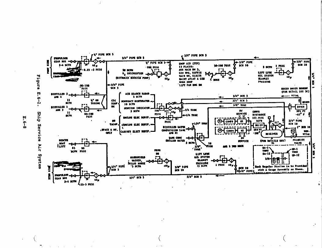
.-
-b.1
‘o●
i8:m,1l-l
.s
T
.
,
w
.
3_
FigureE.6-2.
ShipServiceAirSystem
E.6-8
1’
‘.-.’
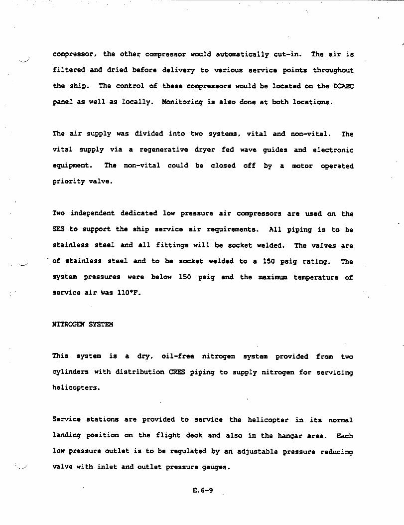
..-/”
‘.--’
.-”
*
compressor, the otheq compressor would automatically cut-in. The air is
filtered and dried before delivery to various service points throughout
the ship. The control of these compressors would be located on the DCAE%
panel as well as locally. Monitoring
The air supply was divided into two
is also done at both
systems, vital and
vital supply via a regenerative dryer fed wave guides
equipment. The non-vital could be” closed off by a
priority valve.
locations.
non-vital. The
and electronic
motor operated
Two independent dedicated low pressure air compressors are used on the
SES to support the ship service air requirements. All piping is to be
stainless steel and all fittings will be socket welded. The valves are
of stainless steel and to be socket welded to a 150 psig rating. The
system pressures were below 150 psig and the maximum temperature of
sewice air was llO°F.
This system is a dry, oil-free nitrogen system provided fr~ two
cylinders with distribution CRES piping to supply nitrogen for servicing
helicopters.
Service stations are provided to service the helicopter in its normal
landing position on the flight deck and also in the hangar area. Each
low pressure outlet is to be regulated by an
valve with inlet and outlet pressure gauges.
E.6-9 ,
adjustable pressure reducing

The nitrogen is to be pre-purified dry, per Type I, Class 1, Grade A.-w’
Specification BB-N-411b, and stored in cylinders per MS-39224-6 with
service pressure of 2265 psi and 230 SCF capacity (cylinder volume is
2640 cu. in.). To provide
was used. The booster was
from the service air system.
nitrogen at 3000 psig, an air-driven booster
a 30:1 ratio and is driven by 100 psig air
.. ‘d
E.6-10

.--’
APPENDIX E.7
FIRE =INGUISHING SYSTEMS
.
,:

,.. . ,.
NALON 1301 SYST~.---’
Areas containing fl~le fluids are protected by dedicated Nalon 1301
system designed in accordance with NPPA Nanual E2A. Each area protected.
is supplied with a primary and seconda~ supply of halon. Concentration
levels of 5.0 to 7.0
spaces by a 10 second
detection system.
Halon (FE 1301) fixed.
rooms, waterjet pump
percent by volume are developed within
halon discharge initiated remotely by
protected
the fire
flooding system is provided for propulsion engine
rooms, fuel oil pump rooms, machinery rooms,
electric generator rooms, lift fan engine rooms. flammable liquids
storerooms, the gas turbine generator enclosure and the electronic
d equipment enclosures.
Nalon containers
containers for gas
are located local
remote from ~,
of enclosure served.
me located outside the compartment served. Nalon .
turbine generator and electronic equipment enclosures
to the equipment. Operation of system is local and
manual release is accessible outside the compartment
FOAM SYST13S
The AFFF system
hangar, VERTREP
will supply only the aviation facility (landing platform,
area for helicopter
4 The landing platform
and NXFR). Application rates of
hangar foamlwater sprinkler
coverage afforded the SES is
E.7-1
0122 gal/sq ft overhead
systems are maintained.
011 gallsq ft. of foam.

The AFFF system has one 90-1000 GPM delivery from a 2000 gallon capacity
foam proportioning system utilizing a 3% “lightwater” foam concentrate
capable of supplying the worst hazard with foam for a continuous
operation of 10 minutes..
PORTABLE
Portable
EXTINGUISHING
fire extinguishers are 2ocated through the crew’s living areas,
work spaces and areas where s-11 fire hazards may exist. lialon 1211
portable *fire extinguishers replaced the conventional C02 extin~ishers
in their use as described by General Ship Specifications.
This represented in weight and an increase in system performance. Halon
1211 units were
“Lightwater” WFP
w’
augmented with dry chemical (PKP) and PortableL/
units depending on the fire hazard.
w
E.7-2

,,.
APPmlx E.8
HYDFGULIC SYSTEM
.--”
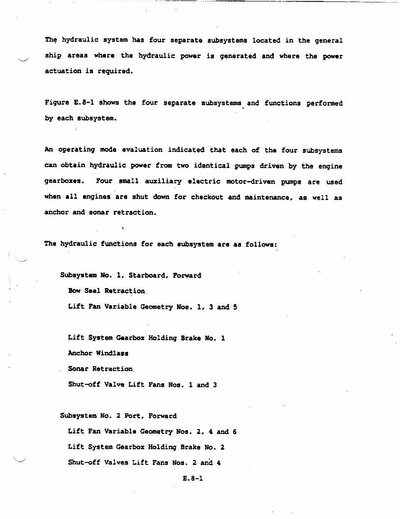
Thq hydraulic system has four separate subsystems located in the general
ship areas where the hydraulic power is generated and where the powere
actuation is required.
Figure E.8-1 shows
by each subsystem.
the four separate subsystems and functions performed.
An operating mode evaluation indicated that each of the four subsystems
can obtain hydraulic power from two identical pumps driven by the engine
gearboxes. Four small auxiliary electric
when all engines are shut down for checkout
anchor and sonar retraction.
motor-driven pumps are used
and maintenance, as well as
The hydraulic functions for each subsystem are as follows:
Subsystem No. 1, Starboard, Fomard
Bow Seal Retraction
Lift Fan Variable Geometry Nos. 1, 3 and 5
Lift System Gearbox Holding Brake W. 1
Anchor Windlass
Sonar Retraction
Shut-off Valve Lift Fans Nos. 1 and 3
“4
Subsystem No. 2 Port, Forward
Lift Fan Variable Geometry Nos. 2, 4 and 6
Lift System Gearbox Holding Brake No. 2
Shut-off Valves Lift Fans Nos. 2 and 4
E.8-1
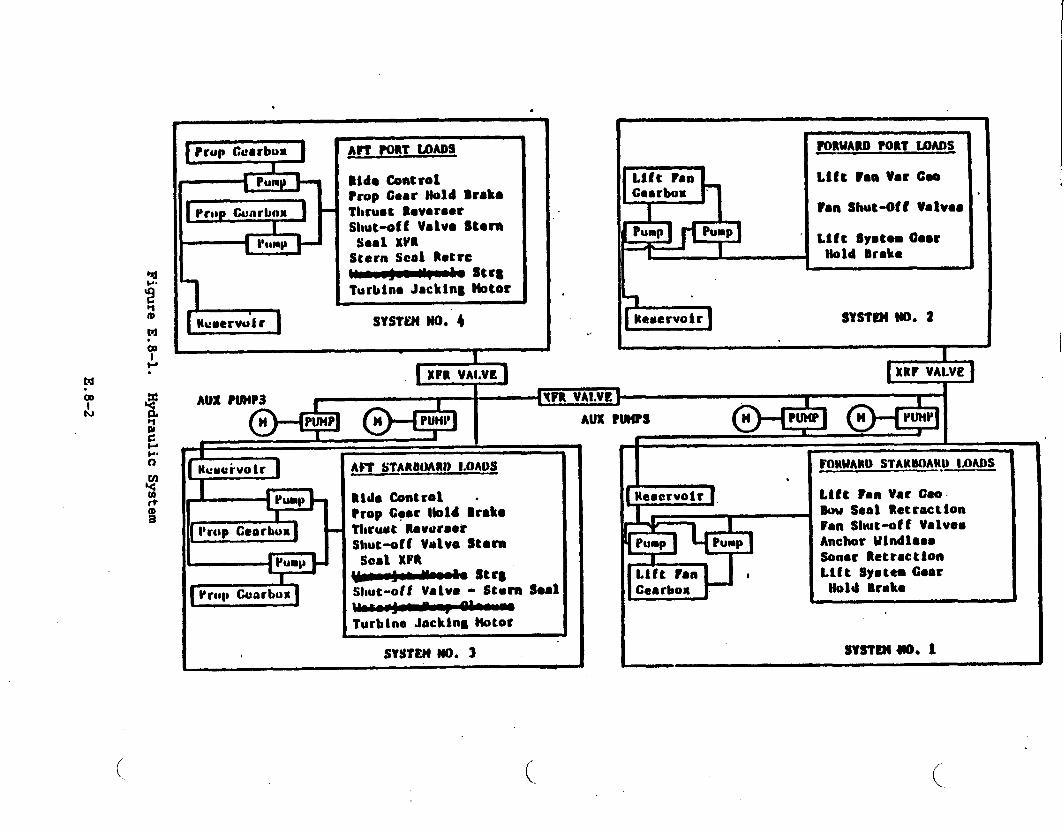
.●
LMcmervulr
APT PORT UMOS
Rid. Control?rop Coar Mold BrshThruot RovoroerShut-off Valv* Stem
Ssal XVRStern Scai Rotrc~ st~tTurlstnaJackln~ Hotor
SYSTS?(No. 4
.
.
4Lift Pan -Cearbox ‘
PORWANI PORT U)MS
Lift Pan VarCeo
?an Shut-Oft Valve.
Lift System ~-rNold Drake
sYsTI!n No. 2
AU% PUW3
m
AFT STARINMRI) LOADS
RWO Control .?rop Cqar I!oldBrakem~r~utROUtir..fshut-off vMivo Stern
seal XFn~ st”8Shut-off Valvo - Stern S.s1
m
I.
Lift FanCearboa
I
MINWAMU STARBOAHO IAWJS -.—
Ltfc ?mmVar GeoW Sent RetractionFan Shut-off ValvesAnchor I#lndlaes
Sonar RetractionLift Systea Goer
Ilohl Drake
sYsTmuo. 1
1
L J
(

Subsystem No. 3, Starboard, Aft
Ride Control (Vent) Valves Nos. 1 and 3
Shut+ff Valve Stern Seal Transfer No. 1
Steering No. 1
Thrust Reverser No, 1
Propulsor Gearbox Holding Brake Nos. 1 and 2
Shutaff Valve
Jacking Motors
Subsystem No. 4,
Stern Seal No. 1 (Fan No. 5}
NOSO 1 and2
Port, Aft
Stem Seal Retraction
Ride Control {Vent) Valves Nos. 2 and 4
Shut-off Valve, Stem Seal Transfer No. 2
Shut+ff Valve Stem Seal No. 2 (Fan No. 6)
Steering No. 2
Thrust Reverser No. 4
Propulsor Gearbox Holding Brakes Nos. 3 and 4
Jacking Motors Nos. 3 and 4
During operation without one of the two lxinksof lift fans,
and 2 may be interconnected by a solenoid valve operation.
subsystems 1
For emergency
purposes any system can be interconnected to any other system through
interconnecting solenoid valves.
Each of the four hydraulic subsystems are powered by two identical 3.0
cu. in./rev., 3000 psig, variable displacement piston pumps. The No. 1
. pump of each subsystem would be set for
d would have full flow at 3000 psig. The
E.8-3
3100 psig at zero
second, or No. 2
output flow and
pump, would be
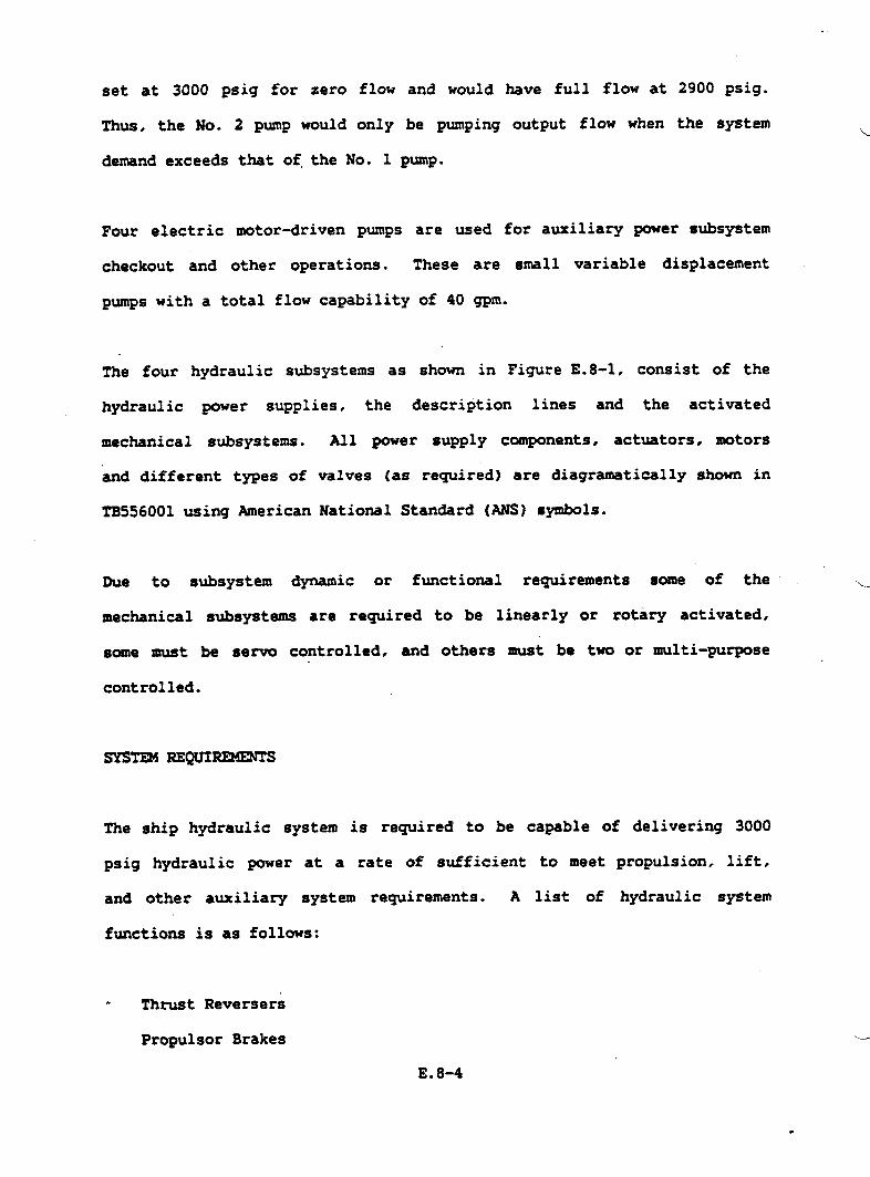
set at 3000 psig for zero flow and would
Thus, the No. 2 pump would only be pumping
demand exceeds that of.the No. 1 pump.
have full flow at 2900 psig.
output flow when the system
Four electric
checkout and
motor-driven pumps are used for auxiliary power subsystem
other operations. These are small variable displacement
pumps with a total flow capability of 40 gpm.
The four hydraulic subsystems as shown in Fivre E.8-1, consist of the
hydraulic power supplies. the description lines and the activated
mechanical subsystems. All power supply components, actuators. motors
and different types of Valves (as -wired) are diaw-ti=lly shown in
TB556001 using American National Stan&rd (ABM) symbols.
Due to subsystem dynamic or functional requirements some of the u
mechanical subsystems are required to be linearly or rotary activated,
some must be servo controlled, and others must be two or multi-purpose
controlled.
SYSTE4 REQUIREMENTS
The ship hydraulic system is required’to be capable of delivering 3000
psig hydraulic power at a rate of sufficient to meet propulsion, lift.
and other auxiliary system requirements. A list of hydraulic system
functions is as follows:
. Thrust Reversers
Propulsor Brakes .-J
E.8-4
Bow Seal Retraction
.-.’Stern Seal Retraction
Lift Duct Valves (including Fan Shut-off Valves and Stem Seal
Transfer Valves]
Ride Control Valves
Lift Fan Variable
Anchor Windlass
Sonar Retraction
Propulsor JacIcing
Tables E.8-I. E.8-2,
Geometry
Gear
and E.8-3 suxmarize the function flow requirements.
It is desired that the system
distribution and be capable of rapid
have lightweight, flexible power-.
response.
J
CANDIDATE CONCEPTS
These candidate concepts for major component arrangement were explored.
a. Central System — The Central
return line running the length
subsystems.
System has one
of the ship to
This system contains five hydraulic pumps.
with a displacement of 4 cu. in.lrev., are
driven while the remaining three pumps, with
main pressure and
supply the various
Two of the pumps,
lift fan gearbox
a displacement of
approximately 1 cu. in.lrev., are ●lectric motor-driven. For
maintenance
and cooling
..and reliability, two complete reservoir, filtration
systems are provided.
E.8-5 .’

,
Tablo E.O-l. Hydraulic Syato. Flow R.quir.ments During Cambined Subsyatern operation
SUBSYSTR4
fkw Seal Retraction (1)~Lift Fan Variable
Geoaetry (6)*Turbine Reduction Gear
I
Holding Brake (61Shut-off Valve-Lift Fan (4)aaShut-off Valve-Stern Seal(2)Anchor Windlaes (1)Sonar operation (IJRide (2mtrol Valve (4)*Shutmff Valve Stern
Seal Transfer (2)Ste.ring Vectoring (4J~Thrust Reverser (2)6StarnSealRetraction (1)TOTWFTXW IQJIRSD (GPM)
● Servo Valve Leakage
4A%.mRATEW14
40120
.78
.65
201268.8
1.3
2417.620.5
XxK;IDE
2.732.5!5.7
FF-XJSH.)PER.;SA;TATE)-5
2.531.2
.52
1.61.3
2432.538.4
●* Valvee oDer. beforg or ●ftar fan Oper.●*s oper~ted-oneat a ti~
●aas servo Valve system shut-off ●t dockside
3KSES OPERATIW~DPARTIAL ICN CUSHICN
--E3JSH. ~:
3PSR.93A SEASTATS STATlb-9 o-3
2.5 2.562 62
.26 -
16.5 34
24 243 32.5 2.5
79.96 120
mIIGNXA;TATSk-6
2.5k20
68.8
2432.5
;20.8
41(WSPSSD:RUISESSASTATSD-6
2.5120
68.8
2432.5
220.8
Mm.WLSX?w-rSTOPP~
2.53
.78
129
2.732.5
35.48
‘NITIAL-
4031..2
17.5
2417.620.5
150.8
‘ STOPFINAL
2.53
.78
91.3
2.732.5
24.8
WCOVSRV
2.53
.52
20 .
2417.6
2.s25.12

Tablo ft.8-2. Hydrwlic Syctom~Deta
NAXIIURI PLat PsRPw4P“RR’@ m AT WIMJN NIR4BEROF TOTALPunP TOTAL
sussYsTw SPSED, DISP~ PLOW sPEm PuNPs Pm DISP~ PWP P(LWNo. DRIVE m CU. IN./REV. GPN SUBSYSTR4 CU. IN/RSV. GPN
1 No. 1 Lift 5600 3.0 70 2 6.0 140RtductionGear
2 No. 2 Lift 5600 3.0 . 70 2 6.0 140Reduction Gear
6.0 118
3 No. 1 Propulsor 4800 3.0 59Reduction Gear
No. 2 Propu180r 4800 3.0 59Reduction Gear 2
4 k. 3 Propuleor 4800 3.0 59Reduction Gear
No. 4 Propuleor 4800 3.0 59Reduction Gear 2 6.0 118
Tablo 8.S-3. Auxiliary Pwp Deta
SLSCTRICWTOR PUMP PUNPIWMNU148EROF DRIVS SPSSO, DISPLAC~ SAcN PUNP,
PUNPS RPN CU. IN/REV. GPN HP
4 , 7600 0.4 10 20
b. Modified Central System — This system includes two Pumps Per
lift fan gearbox; othemise, it is the same as the central system.
c. Dual System —The Dual System divides the baseline system into
two separate subsystems, port and starboard. Each subsystem is
powered by three main system pumps. One 4 cu. in./rev. pUIW is
driven by the lift fan gearbox while two 3 cu. in.frev pumps are
mounted on the tw propulsor gearboxes (totaling six pumps for
the Dual System). This system also provides two auxiliary
electric motor-driven pumps of 0.42 cu. in.lrev.capability
for system maintenance ud for operating the waterjet
closures prior to startup of the engines. The
contains two reservoir-filter - cooler groups,
subsystem.
d. Quad System — The Quad System divides the baseline
system
one in
each
pump
also
each
system into 4
w<
separate hydraulic subsystems. These ‘ separate hydraulicu
subsystems are located in areas adjacent to pump power
suppliers. The Quad System uses eight hydraulic pumps (3 cu.
in.trev. each) - two pumps for ●ach of the four subsystems. The
system also provides four electric motor4riven pumps of 0.42 cu.
in./rev. each; these units are used for system maintenance.
The major weight of hydraulic systems is concentrated in the piping and
associated hydraulic fluid. The Central system has large pressure and
return lines running the iength of the ship. The Dual System contains
slightly smaller pressure and return lines with two sets running the
length of the ship. The Quad System has the smallest pressure and return
lines. These lines are located in”the area adjacent to their pump power
supply. L/
E.8-8

The Central System cannot be effective during a single lift engine
J’ operation nor during a lift engine-driven failure. The modified Central
System does have adequate flow capability during the aforementioned
condition; total pump displacement is 19 cu. in./rev. (CXR).
The Dual System with a total of 3 major pumps and a combined displacement
of 24 CIR provides the desired total flow margin and also provides
functional growth capability for added ship functions.
PUMP S-ION
A variety of hydraulic pumps are available. Some of these can operate
only at low system pressure while others are capable of operating at high
pressure. The selected system pressure is 3000 psi, which narrows the
._/’ field to the use of piston type
fixed or variable displacement.
The fixed displacement pump will
Pumps“ Piston pumps are made in either
always deliver its maximum flow rate are
driven speed. If the required flow rate at some time is less than the
maximum then the excess flow is bypassed through a relief’valve which
adds
ship
one
heat into the system. The pump delivery requirement for different
operative modes indicates a flow rate range of from 2 to 64 gpm in
of the four Quad Systems. This would mean almost continuous
operation of the relief
Variable displacement
valve.
axial piston pumps maintain a nearly constant
system pressure range by varying the output flow rate to meet system
-d
demand. The displacement or output flow is pressure controlled. If
E.8-9
there is no system demand, the pump yoke will position the piston
assembly for minimum displacement to hold 3000 psi pressure. When a
system demand is made, by usually opening a valve to a subsystem, the
pressure starts to drop. The pmp pressure control senses this pressure
drop and positions displacement (and output flow) to hold the pressure.
The pump will have minimum flow at 3000 psi and maximum flow at
approximately 2900 psi pressure. Thus, the added heat to the system is
minimized by using a
mechanical and volumetric
rated input power.
The pump type selected is
HYDRAULIC FLUID SELECTION
Many hydraulic fluids
variable displacement pump with its normal
efficiency losses only approximately
the variable displacement type.
are available of different
characteristics but all are essentially one of two basic
‘e’
13% of the
‘“w’
formulation and
types; petroleum
base and synetic. The synthetic type fluids can be separated in
chemically compounded and water base hydraulic fluids. Synthtic fluids
are formulated from compounds which are made chemically resistant to
burning by the addition of snuffer agents, usually water, to flamnable
compounds to fom water base fluids. Water alone, or with soluble oil
additives to increase lubricity and reduce mtingr is used in some
industrial applications where large quantities of fluid due to its
restrictive liquid range. high viscosity, low lubricity and corrosive
capability.
u
E.8-10
.
TWO types of hydraulic fluids are presently in use or being planned for -
d future operation of surface effect ship+; hydraulic fluid in accordance
with MIL-H-5605 is employed in the SES 100-Ton Testcraft, and fluid per
MIL-H-83282 will be used in the Amphibious Assault Landing Craft.
Hydrofoil crafts such as PCH-l and Dennison have phosphate ester based
(S~drol) hydraulic fluid in their system.
Hydraulic fluid that meets Specification MIL-H-5606 has been in use for
more than 30 years and is generally accepted as the hydraulic fluid in
industry. It is a petroleum-base fluid, it possesses desirable
characteristics of viscosity behavior with temperature variation and good
lubricity for moving components. The drawback is its low flash point.
\
Phosphate ester hydraulic fluid (Skydrol) was developed primarily for
J“ aircraft systems to improve the fire resistant properties over
MIL-H-5606. However, this fluid is toxic and incompatible with many
materials such as stan&rd seals of Buns N and Vitou materials, painted
surfaces, electric wire insulation etc.
Historically, fire resistant phosphate ester base fluid. in accordance
with MIL-H-194S7, has been used in some Navy ship applications.
this fluid has the problems of toxicity,
aircraft type components qualified for it.
seal compatibility
To overcome these
However,
and few
types of
problems, MIL-H-83282 fluid has
MIL-H-83282 fluid is a new
recently been developed.
synthesized hydrocarbon fluid that was
developed to provide both improved’performance and safety as compared to
wexisting hydraulic fluids. Some of the advantages of this fluid are:
E.8-111
.
a. High operating temperatures and improved themnal characteristics
which allow system operation to at least 400”F. w
b. Improved fire resistance flammability characteristics, resulting
in reduced hydraulic fire hazards related to petroleum-base
hydraulic fluids.
c. It is non-toxic and requires no’ special precautions such as
required by phosphate ester or similar fluids.
PIPING MATERIAL
The hydraulic lines considered here are the high pressure and return
lines consisting of rigid.,
will be used in general,
locally connect the pumps
and flexible material. Lines of rigid material
and lines of flexible material will be used to
and actuators to rigid main distribution lines.
a. (1) R@id Tubing +3?ES 304-L is the selected material for rigid
tubing: it is readily available in me” rewired t~e
diameters, relatively easy to bend and weld. and is
appreciably less costly than tubing made from 21 Cr-6Ni-9Mn
that requires the procurement of mill runs in sizes greater4
than 1.25 O.D Swaged and weld fittings were selected in
preference to the use of flared fittings in the interest of
minimizing the potential of leakage. Welding is preferred to
brazing because successful brazing requires an inordinate
degree of care and cleanliness, which is costly and difficult
to endure under ship building conditions. Xn addition,
brazed lines must be flushed with water
the flux. followed by drying of the
E.8-12
zany times to removeu
system with acetone
.

d’
followed by alcohol. Inspection is facilitated, since welded
joints can be ultrasonically inspected, whereas brazed joints
are not readily inspectable.
(2) Flexible Tubing — Wherever flexible tubing is used, it will
be Teflon-lined, since rubber turing takes on a static charge
and picks up and holds dirt despite best efforts to clean the
internal surfaces. Rubber tubing also “sluffs off’*‘~rticles
which can damage servo valves. Fittings that are
particularly designed not to damage the Teflon lining will be
employed with this tubing..
b. Hydraulic Line Jointing — The primary
swage and weld type co&iguration to
Where separable lines must be used,
fittings or equivalent is recommended.
fittings will be of the
eliminate line leakage.
the Deutsch or Dynatube
w
Ei8-13

..>’ .
APPENDIX E.9
REFRIGERATION SYSTE24
‘J
.
The refrigeration capacity of each plant is 3/4 ton. Freon 22 has been
.---’chosen as the most practical refrigerant. The following information
gives equipment description and function in detail.
COMPRESSOR
The compressor type is 60 Hz heavy duty reciprocating accessible
hermetic. It is provided with suction and discharge service valves, and
has a force feed lubricating system. The compressor motor is provided
with thermal overload protection as a safety measure.
.
mNDmsER
The condenser is the shell and tube type in whichd
through the tubes within the shell. The condenser is
water circulates
equipped with a
seawater flow valve which is controlled by the refrigerant discharge
pressure.
RECEIVER
The refrigerant receiver has the capacity to hold at least 110 percent of
the no-l operating refrigerant charge. The liquid outlet is covered by
liquid at all times during pitch or roll conditions of the ship. The
receiver has two fused quartz sight glasses equipped with float bills to
determine the refrigerant level. The receiver is designed for a test
._--’
pressure of 450 p8ig.
E. 9-1

PRESSURE SWITCX
Pressure switches are provided in the suction and discharge lines from
the compressor. The suction pressure switch is a sin91e pie. single
throw switch with automatic reset on pressure rise. It will uhut down
the compressor when there is a low level of refrigerant or when
refrigerant flow is stopped by the liquid solenoid valves. The discharge
pressure switch is a single pole double throw switch with manual reset.
It will shut down the compressor and actuate an slam circuit in the
event of an overpressure condition.
FILTER-DRYER
The filter/dryer is the replaceable core type. The core material removes
water, acid,
installed with
SIGHT GLAss
A refrigerant
evaporator.
and particulate matter from the refrigerant. It is
isolation valves,f which are used while replacing the core.
flow sight glass is provided in the liquid line to the
The sight glass
indicator. The sight glass with
filter/dryer cartridge fitting.
--
EVAPORATOR
incorporates a color code
moisture indicator is combined
moisture
with the
The evaporators are the fan forced circulation
both the Chill and Freeze rooms. The evaporator
E. 9-2
type. There are two in
coil is the copper tube ‘--_-’

., :. .,.,,’... ,.’. .’ -.. “..’ ,. .-, ‘,
type and is mechanicall.ybonded to the aluminum fins. Fin spacing is
d
compatible with sub-zero evaporating temperatures. The evaporators and
fans are enclosed in an aluminum housing arranged for overhead mounting.
-ANSION VALVE
Each evaporator is served by a thermostatic expansion valve. The valve
is compatible with both the operating mode and the defrost mode. It is
constructed so that all working parts may be replaced without removing
the valve body
SOLENOID VALVE
from the piping system
Each evaporator/.—
the refrigerated
SUCTION PRESSURE
is controlled by a solenoid valve which is sner~ized by
space thermostat.
REGULATOR
The chiller room eva~rator suction lines are provided with suction,
pressure regulators. They control the evaporating temperature needed to
produce the capacity required in the chiller mode without freezing of the
evaporator. The regulators are internally regulated. A full line-size
manual bypass valve is provided
CRANKCASE PRESSURS RHWLATOR
The compressor regulator whiche
condensing unit. The regulator
for operation in the freezer mode.
is provided in the suction line to each
prevents the suction pressure from rising
E.9-3
beyond a pre-detemined limit during a period of pull-do-, when the room.’
temperatures are abnomally high. This control is optional depending on u’
compressor selection.
HEAT EKHANGER
Heat exchangers are used to fully vaporize the suction gas. or to further
sub-cool the liquid refrigerant. This component is optional depending on
compressor selection.
MANUAL VALVES
Manual valves are of the diaphragm globe type in full line size.
CONTROL REQUIREMENTS
The refrigeration system requires tith remote and local controls systems.
~OTE CONTROLS DESCRIPTION .*
The refrigeration system remote controls command the operation of the
evaporators and fans for system Number 1 and system Number 2.
Refrigeration system Number 1 controls one evaporator and one fan in the
Freeze Room, and one evaporator and one fan in the Chill Room. Similar
controls apply to refrigeration system Number 2. The off comand is the
only remote control rewired for ~ (in the Central Control Station)
from the refrigeration system. ‘“
“2’
w
E. 9-4
,.
The refrigeration system is normally in continuous operation and would be
.1
shut down only during the defrost mode or an emergency condition.
Reference G.E; Ship Control Ilrawing”SK56137-61-20 for the refrigeration
system IXAEC Control Panel layout.
The refrigeration system command controls and monitor controls will
interface with Data Te~inal Number 3, which will receive and tr==~it/
these signals to and from the _ panel in the central control station.
-OTE CONTROL FUNCTIONS
Remote control functions are as follows:
a. Comands
1. Refrigeration System No. 1 - off control only
2. Refrigeration System No. 2 - off control only
b. Monitors
1.
2.
3.
4.
5.
6.
Freeze Room high temperature alarm
Chill Room high temperature alarm
Refrigeration
Refrigeration
Refrigeration
Refrigeration
System No. 1 status
System No. 2 status
System No. 1 fault alarm
System No. 2 fault alarm
*
w
E. 9-5
La CONTROL DESCRIPTION
w;
The local control panel -is located in the Refrigeration Machinery Room.
The local operator will be able to perform all operations and controls of
system Number 1 and, including startt stop, and defrost functions. THe
front panel contains switches and indicators labeled according to their
function. The rear of the panel contains relays, contactorst and
terminal boards.
_ CONTROL FUNCTIONS
The main function of the local control panel is to start up refrigeration
system Number ql and Number 2, and maintain continuous operation until
defrosting or nmintenance is required. The local control operator amy
then shut down the system by either depressing the on/off switch to the b’
off position, or depressing the defrost switch. The later action turns
on the defrost heater(s) that begin the defrost sequence. After defrost
or maintenance is completed, the on/off switch is depressed to the on
position, and normal operation is resume.
There are two maintenance switches, one for system No. ~. one for system
No. 2. These switches are used to trouble-shmt the freeze and chill
systems by opening the thermostat paths and also the paths to the
refrigerant valves, isolating problem areas.
The chill room has the capacity to be used as either a chill or freeze
space. Therefore, a chill~r/freezer select switch has been proved on the
local control panel to select the desired mode for the space. Theu
E.9-6
heal/remotm select switch is used to put ‘the system either in local or-/
remote control mode. If in the local” mode of operation. the system
cannot be turned off by the remote operator. If in the remote mode of
operation, only the remote
Refrigeration System Controls
The 3KSES Auxiliary Systems
with the ship specification
operator will shut down the system. See
Diagram, Figure E.9-1.
Specification was developed in accordance
and implicates Section 516 of the GSS and
MIL-R-16743.
The intent of
Refrigeration
reduce weight
d the following
Section 516 has been followed in the development of the
system. but not strictly adhered to. In an effort to
and complexity without sacrificing performance or safety,
requirements per Section 516 have not been incorporated in
the Refrigeration system.
a.
b;
c.
d.
Interchanger on the liquid line with shut off valve. (Having two
refrigerant plants eliminates the need for this valve).
Replacement charge of R-22 and lubricating oil-, one per plant,
(Two independent plants eliminates the need for redundant service
materials).
NAVSHIPS Drawing No.
penetrations. (This
810-1385899 to be used for refrigeration box
stan&rd penetration was determined to be
too complicated and-unnecessary).
Hot gas by-pass between compressor discharge
valve. Hot gas control valve, and additional
and expansion
solenoid valve.
(Function replaced by evaporator pressure regulator and electric
defrost).
E.9-7 ,

ti
.
‘L-Z-Z ----’--+ --r--l r--l-.-”r~ ‘[-~ . . . .
M
,** ~ _.I-i $ ~------ ---- J-J.---Y--- –--”--- -J-: Ct
(
.,..,. :.. . .. . . “.: ‘.’.—
,,,
e.
J
f.
9=
h.
J
i.
Portable vacuum pump, hoses, and a&ptor for evacuating and
dehydrating refrigeration system to be stored o-rd.
(Impractical from a weight standpoint. See Item b.).
Provide separate refrigeration circuits for
space, with valves to cut off service.. (In
separate circuits for each space because
each refrigerated
effect, there are
of two separate
systems. Because the refrigeration system is not a standard
system, the valves are not needed).
Distribute air by means of duct work. (Compartment size is such
ducting is not required).
Coil defrost to be accomplished by means of hot seawater spray.
(From a weight standpoint (additional piping system) and system
simplification, electric defrost was determined to be a more
practical defrosting method).
All safety control as invoked by
The 3KSES Auxiliary System was reviewed
MXL-R-16743.
by the Navy. They requested the
following be added to the specification: “The refrigerating units shall
be provided with operating and safety controls as required by
MIL-R-16743“. Because the refrigeration system is not the type usually -
installed in Naval vessels, this could not be added without redesigning
the system, adding the weight and complexity of a typical system. The .
Navy then agreed that we would.instead follow the”intent of MIL-R-16743,
without sacrificing safety or perfo-nce. This has been accomplished,
and listed below are the operating or safety controls not relevant to the
current design configuration.
.J
a. Oil failure switch
E.9-9

. .
b.
c*
d.
e.
f.
9*
h.
i.
j“
Oil indicator
Water failure switch
Shut-off valve (between condenser and receiver)
Pressure relief valve (bypasses shut-off between condenser and
receiver).
Hand expansion valve (bypass there expansion valve).
Shut-off valves (at evaporator outlet for each cooling coil).
Liquid line strainer (in addition to dehydrator/filter).
Suction line strainer (between suction shut-off and compressor).
Moisture indicator (in addition to sight flow indicator).
w
Heat load circulation for the refrigeration system have been performed in
accordance with DDS 516-1, and equipment is sized and selected
accordingly. There have been some tradeoffs with regard to equipment. d
Initially, a centrifugal type compressor was considered, but commercial
availability was poor, and it was not particularly suited to the system.
A 60 Hz hermetic compressor is the current selection; it is heavier. but
less expensive, readily available, and suits the refrigeration
application. The major tradeoff in the refrigeration system is”the use
of the split system. which was chosen over the standard system primarily
for reliability. Each system serves the chill and freeze room. In the
event of a system failure, the other system will be employed, insuring
maintained compartment temperatures.
E.9-10

APPENDIX F
WEIGHT ESTIMATE
.
.--’
0
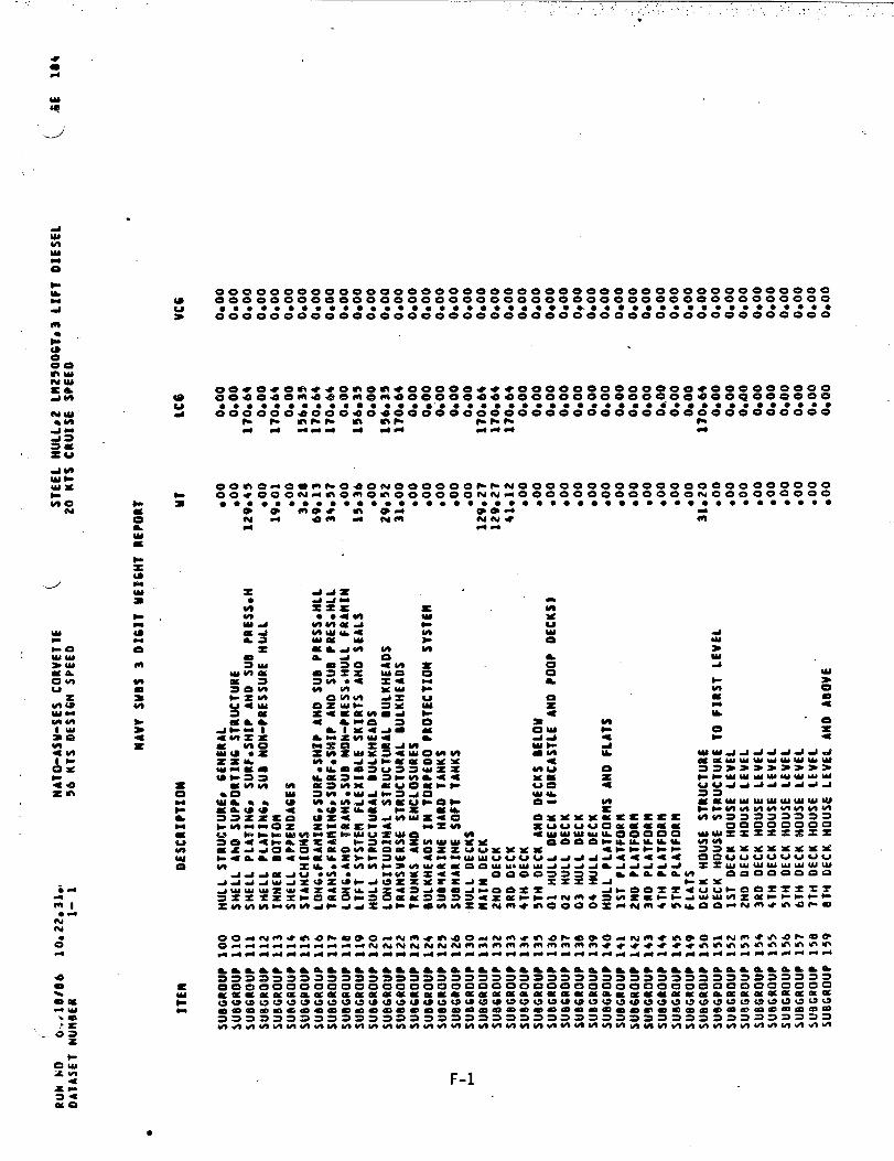
.
Lzm
Ooeooooooooeo 000000000000000000000000 0000000000000000000000000000000000 0000000000000000000
● ● ● ● ● ● ● ● ● ● ● ● ● ● ● ● ● ● ● ● ● ● ● 9*O 0.00 ● ● ● ● ● , ● ● ● ● ● 0 ● ● ● ●0000000000000000000000000 00000000000000000000
d
m
oo*o*om**omo -+*00000***00 Oooooooooooe 000000000eo4f340-4.9=me meoooooaeeoo 000000000009 ooQoooeo’o
● ● ● * ● ● ● ● ● ● ● ● ● * ● ● “0 ● ● ** ● *** ● ● ● ● ● ● ● dO** ● ● ● ● * 80 ● ●oogo:og:gego $goeooog~goo 00000000000: oooooeooo
dd &d* - -d dd- d
0000-$0---040 6JOOOOOO**NO0 00000000000000000000000#0OOWAmOmO -OOOOOOfUtUdOO 0000OOOOOOON 000000000G*; ●$ ●**$** ●mo●**: ● ● * ● ● ● ● ● 0 9 ● ● ● ● *** ● ● ● ● ● ● ● ● ● ● ● * ● ●
tud g- d mmH
w>0:
0xa
ra0lbk-4z
UIo
Xr)-+*Q
axa+a.#
a0m
F-1
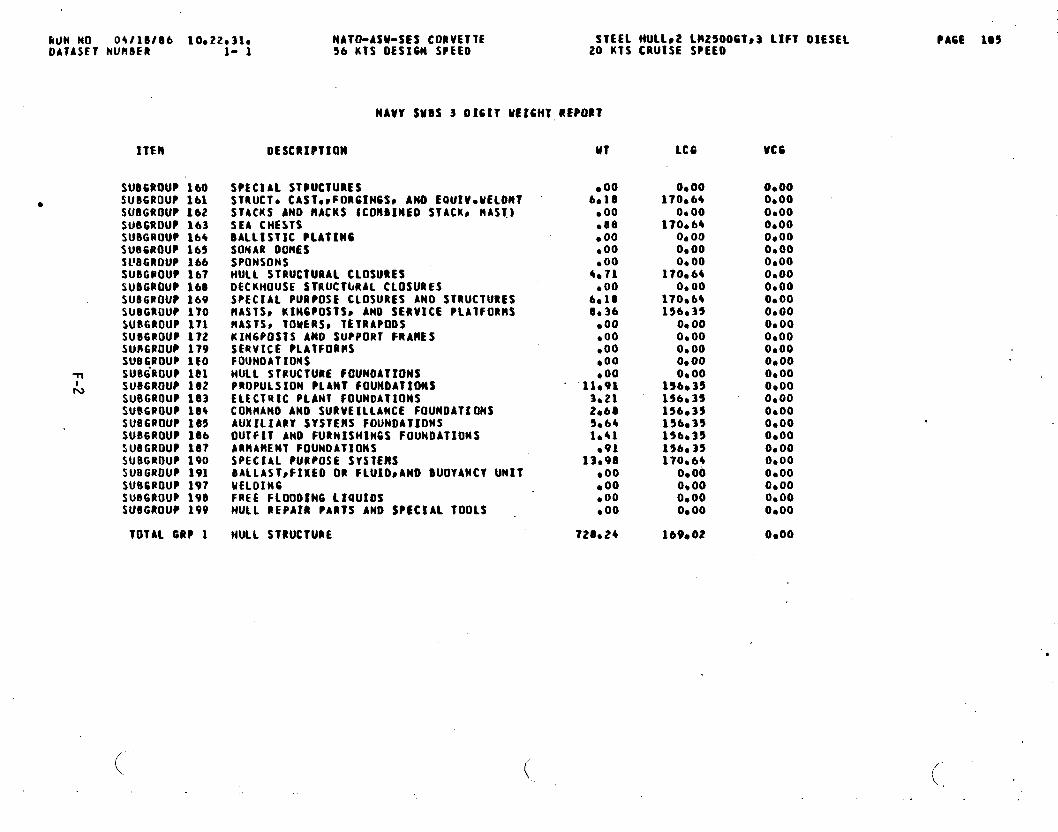
kUN NO 04110186 10e22e31e NATO-ASU-SES CORVETTE STEEL HULLF2 LH25006Ts3 LIFT OXESE1OATASFT NURBER 1- 1 56 KTS DESIGN SPEED 20 KTS CRUISE SPEED
PAGE 105
NAVY SUBS 3 0161T UEICHT REPCIRT
ITEM
SUBCROUP 140● SUBGROUP lbl
SUllGROUP 162SUBGROUP 163SUBGROUP 164SUBGROUP 165$llBGRouP ~~4SUBGPOUP 167SU8GROU? 160SU86@OU? 169SUBGROUP 1?0SURGROUP 171SUBGROUP 172SUBGROUP 179SUS6ROUP lEO
w SU86ROUP lClL SUBGROUP 102
SU9GROUP 103SU86POUP 10+sue6aauP 165SUB6ROUP 106SUBGROUP 187SUBGROUP 190SUBGROUP 191SU86ROUP 197SUBGROUP 190SU8GROUP 199
TOTAL 6RP 1
DESCRIPTION
SPECIAL STMICTUBISSTRUCT* CASTOCFORG1N6S0 ANO EQUIVOME1OHTSTACKS ANO ltACKS (COHDINED STACKp MAST.]SEA CHESTSBALLISTIC PLATINGSOMAR MIRESSPONSONSHULL STRUCTURAL CLOSURESDECKHOUSE STRUCTLIRAI. CLOSURESSPECIAL PURPOSE CLOSURES AND STRUCTURESflASTSS K1N6POSTSS AND SERVICE PLATFORMSMASTSS TOMERSS TETRAPODSKIN6POSTS ANO SUPPORT FRANESSEQVICE PLATFORMSFOUNOATXOHSHULL STRUCTURE FOUNDATIONSPROPULSION PLANT FOUNOATIOMSELECTRIC PLANT FOUNDATIONSCORHAND AND SURVEILLANCE FOUNDATIONSAUXILIARY SYSTENS FOUNDATIONSOUTFIT ANO FURNISHINGS FOUNDATIONSARMAMENT FOUNDATIONSSPECIAL PURPOSE SVSTENSBALLASTsFIXED OR FIUIDSANO BUOYANCY UNITMELDINGFREE FLOODING L1OUIOSHULL REPA!R PARTS AND SPECIAL 100LS
MULL STRUCTURE
(.
MT
.006a18
● 00●B8● 00●OOboo
4.?1●OO
6s108,36
boo●OO●OO●OO.00
11*913*212*6S5*641.41
●9113,9B
●OOb 00●OO●OO
728*24
LCG
Oboo170e6+
O*OO170,64
Oe00ObooO* 00
170064o* 00
170s6+156,35
Oe00O*OO0.00O*QOOboo
156s35156,3515603!I156s3$156c351S6,3517006~
0.00O*OOO*OOo* 00
lbVe02
VC6
O*OOo* 00O*OO0,00O*OO0.00O*OO0.00O*OO0.000900O*OOO*OOOaooO* 00Oboo00000,000.00O*OOO*OO0.000.000.00O*OO0.000000
0,00
(,
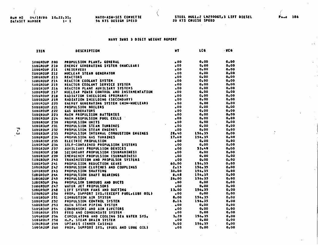
( (“RuN NO 04/10f@6 10s22031oOATASET NUMBER 1- 1
ITEN
SUBCROUP 200SUBGROUP 210SUB6ROUP 211SUOGROUP 212sUBGROUP 213SU8GROUP 214SUBGROUP 215SUBGROUP 216SUBGROUP 217SUB6ROUP 2L@SUBGROUP 219suBGeouP 220SUB6ROUP 221SUBGROUP 222SUBGROUP 223SUBGROUP 224SUBGROUP 230SUBGROUP 231
~ SUOGROUP 232u SUB6ROUP 233
SUB6ROUP 234SUBGROUP 235SUBGPOUP 236SUBGaOUP 237SUBGROUP 230SUB6ROUP 239SUBGROUP 240SUBGPOUP 241SUBGROUP 242SUBGROUP 243SUB6ROUP 244SUBGROUP 245SUBGROUP 246SU86ROUP 247SUBGROUP 248SUBGROUP 250
,. SUBGROUP 251SUBGROUP 252SUBGROUP 253SUBGROUP 254SUBGROUP 255SU9GROUP 256SUBGROUP 258SUBGROUP 259SUBGRJUP 260
NATO-ASU-SES CORVETTE\
STEEL HULLS2 Ln2~oOGT~3 LIFT DIESEL56 KTS OES16N SPEEO 20 KTS CRUISE SPEED
DESCRIPTION
NAVY SUSS 3 01611 UEIGMT REPORT
PROPULSION PLANls CENtRALENER6Y 6ENEBATIN6 SYSTEM tNUCLEAR)lRESERVEO)NUCLEAR STEAM GENERATORREACTORSREACTOR COOLANT SYSTEH.REACTOR COOLANT SERVICE SYSTERREACTOR PLANT AUXILIARY SYSTEMSNUCLEAR POUER CONTROL ANO SNSTRNENTATIONRAOIATION SHIELOIN6 lPRINARY)RAOIATION SHIELDING (SECONOARYIENERGY GENEBATIN6 SYSTEM (NON-NUCLEARJ?ROPULSION 801LERSGAS GENERATORSRAIN PROPULSION IIATTEREESltAIN PROPULSION FUEL CELLSPROPULSION UNITSPROPULSION STEAK TURBINESPROPULSION STEAM ENGINESPROPULSION INTERNAL COMBUSTION EN61NESPROPULSION 6AS TURSINESELECTRIC PROPULS1ONSELF-CONTAINED Propulsion SYSTEMSAUXILIARY PROPULSION OEVICESSECONOARY PROPULSION ISUBNARINES)ERER6ENCY PROPULSION tSUBHARINESiTRANSIIISSION ANO PROPULSOR SYSTEllSPROPULSION REOUCTION 6EARSPROPULSION CLUTCHES ANO COUPL1N6SPROPUL$1ON SHAFT1N6PROPULSION SHAFT SEARIN6SPROPULSORYPROPULSOR SIIROUOS ANO OUCTSMATER JET P80PULSORSLIFT SYSTEM FANS ANO 0UCTIN6PROP* SUPPORT SYSOtEXCEPT FUELCLUBE OILlcon8usrIoN AIR SYSTEMPROPULSION CONTROL SYSTEMHAIN ST[AH PIPIN6 SYSTEMCONOENSORS ANO AIR EJFCTORSFEEO ANO CONDENSATE SYSTEMCIRCULATIH6 ANO COOLIN6 SEA UATER SYSOH-P, STEAM ORAXN SYSTEMUPTAKES (INNER CASING)PROPO SUPPORT SYSO (FUEL ANO LUtE OIL)
●OO●OO●OO●00●OO●OO●OO●00●OO●OO●OO●00● 00● 00●oo●00● 00●00●OO
20.4017060
●00● 00● 00●00● 00●00
60.002*I5
300000060
26000● 00●00
13000●00
00008016
●00● 00,00
3020●00
5000eoo
LC6
00000.000.00O*OO0.000.000000O*OO0.00O* 00O*OO00000000O*OOO* 0000000s 000.000000
156035156,35
00000,00
53,4900000.000.00
156,35156035156035156035156-35
0000O*OO
156,350.4)0
156035156035
O* 000.00o* 00
1560350.00
156,350.00
, VCG
0000O*OO0.0000000.000.000.0000000.0000000.0000000.000000O*OO0s000000O*OOO*OO0.000.0000000.000000O*OOO*OO0000O*OO0.000.000.000000O*OOO*OO0.000.0000000.00O*OO0.000.000.000.000.000.00
.
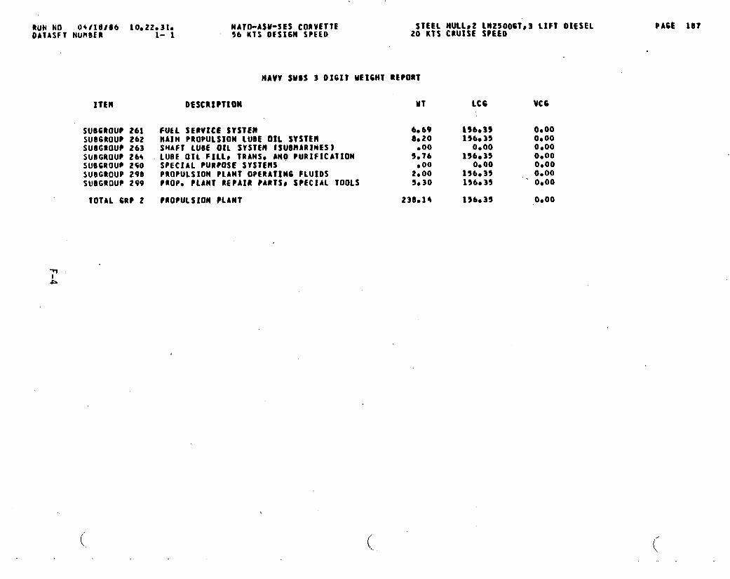
RuN NO 04/ld166 IOO22O31OOATASFT NUMBER
MATO-ASU-SES CORVETTE STEEL HULLS2 km25006Ts3 LIFT OIESEL1- 1 56 KTS 0ES16N SPEED 20 KTS CRUISE SPEEO
ITEM DESCRIPTION
NAVV SUBS 3 DIGIT wEIGHT REPORT
SUSCROUP 261 FU6L SE@VICE SYSTEMSU06ROUP 262 MAIN PROPULSION tUEJE OIL SYSTEMSUSGROUF 263 SWAFT LU6E OIL SYSTEIl ISUBHARINES)SUBGROUP 26+ LUBE OIL FILLp TRANS. ANO PURIFICATIONSUBGROU? 250 SPECIAL PURPOSE SYSTEMSSUOGROUP 290 PROPULSION PLANT OPERATING FLUIDSSUBGROUP 299 PROPO PLANT REPAIR PARTSO SPECIAL TOOLS
TOTAL 6RP 2 ?ROPULSION ?l.ANT
MT
6*690020boo
Y*76b002.005*30
230s14
LcG Vcc
15b035 O*OO156*35 O*OO
0.00 O*OO156035 O*OO
0.00 0.00156.35 0.00156.35 ‘ 0.00
156.35 O*OO
(.. ,.
(..
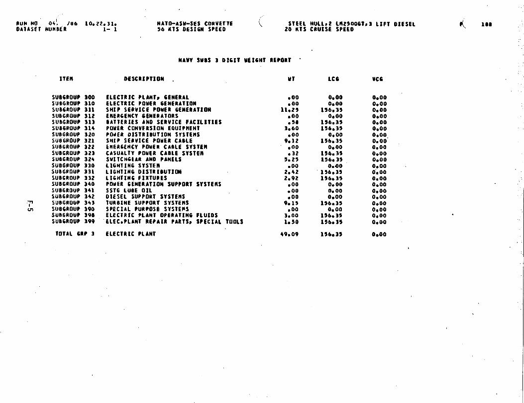
/@uN NO O+; 18b 10022*31o NATO-ASU-SES CORVETTEDAIASFT NuRBER 1- 1 56 KTS DESIGN SPEEO
ITEN
SUD6tOUP 300SUBGROUP 310SUB6ROUP 311SUB6ROUP 312SUBGROUP 313SU86ROUP 314SUBGROUP 320SUBGROUP 321SUOGROUP 322SU8GROUP 323SU86ROUP 324SUBGPOUP 330SUBGROUP 331SUBGROUP 332SUDGROUP 340SUBGROUP 341SUB6@OUP 342
~ SUBGROUP 343ul su06RouP 390
SUB6ROUP 390SUBGROUP 399
TOTAL 6RP 3
MAW SUBS 3 DIGIT ME16HT REPORT
STEEL MULL02 LM2500G1s3 LIFT DIESEL20 KTS CRUISE SPEED
DESCRIPTION . u?
ELECTRIC PLANTs GENERALELECTRIC POUER GENERATIONSMIP SERVICE POMfR GENERATIONERER6ENCV 6WERATORSDATTERIES ANO SERVICE FACILITIESPOMER CONVERSION EQUIPNENTPOdER DISTRIBUTION SYSTEHSSHIP SERVICE POUER CABLEEHER6ENCY POUER CAOLE SYSTEllCASUALTY POUER CABLE SYSTEMSUITCH6EAR ANO PANELSLIGHTIN6 SYSTEMLIGHTIN6 DISTRIBUTI(NIL16HTIN6 FIXTURESPOUER GENERATION SUPPORT SYSTEMSSST6 LUBE OILDIESEL SUPPORT SVSTENSTURBINE SUPPORT SYSTEMSSPECIAL PURPOSE SYSTEPSELECTRIC PLANT OPERATING FLUIDSELECOPLANT iREPA18 PARTSS SPECIAL
● 00●00
11025.00.58
3ab0●oo
9012● 00.32
5*25,00
2*422.92
● 00● 00●OO
9.15●OO
3.00TOOLS 1050
ELECTRIC PLANT 49*O9
LCG
0.000.00
156.350.00
15b03515b,35
0.00156.35
0.00156.35156* 35
0.0015b.3515bc35
0.000.000.00
156.35Oe 00
156.3515ba 35
156,35
UC6
0.00OeOOO*000,000.00O*OO0,00.O*00O*OO0.00O*OO00000.0000000.00O*OO0.00ObooO*OOO*OOO*OO
0000
.,
K 180
.
I
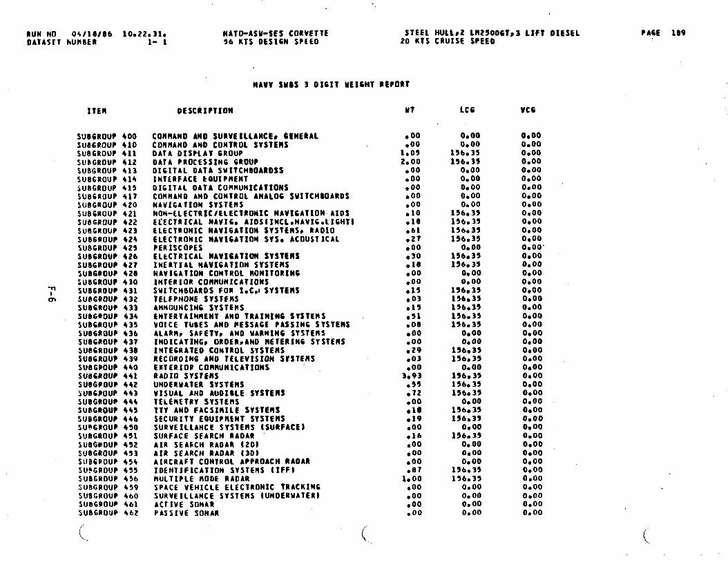
hUN NO 0$l18f8b 10022*31eOATASET kUR9ER 1- 1
ITEN
SUBGROUP 400SUB6ROUP 410SUBGROUP 411SUBGROUP 412SUBGROUP 413SUB6ROUP 414SUB6ROUP 415SUBGROUP +17SUBGROUP 420SUBCROUP 421SU86ROUP 422SUBGROUP 423SUB6BOUP 424SUBGROUP 425SUB6RDUP 426SUBGROUP 427SUD6POUP 420SUBGROUP 430
~ SUB6ROUP 431m SUB6ROUP 432
SUBGROUP 433SUB6@OUP 434SUBGROUP 435su06Rou@ 436SU06ROUP 437SUEJ6ROUP430SUB6ROIJP 439SUBGOOLI? 440SU66ROUP 441SUDGOOUP 442bUBC@OUP 443SUBGROUP 444SUBGROUP 445SUBGROUP 44bsu~6Pou@ 450SUBGROUP 451SUOG@OUP452SU8GROUP 453sitB6PouP $54su~GRoup 455SU9GROUP 456SUBGROUP 459SUBGROUP 460SU5GPOU~ 461SUBGROUP 462
NATO-ASU-SES CORVETTE STEEL HULL*2 Ll125006Ts3 LIFT DIESEL56 KTS OESICN SPEED 20 KTS CRUISE SPEED
OESCUIPTIOM
NAVY SUBS 3 0161T UEIGHT REPORT
COMRANDANO SURVEILLANCES 6tNERALCOHliANO ANO CONTROL SYSTEHSDATA OISPIAV 6ROUPDATA PROCESSIN6 GROUPDIGITAL DATA SMITCMOOAROSSINTERFACE EQUIPMENTDIGITAL OATA COMHUNtCATIONSCORN4N0 ANO CONTROL ANALOG SUITCHDOARDSNAVIGATION SYSTEMSNON-LLECTRICtELECTRONIC NAVI6ATION AIO$Electrical NAVICO AIDSIINCLONAVIGOLIGHTJELECTRONIC NAVIGATION SYSTEHSS RADIOELECTRONIC NAVXGATION SYSO ACOUSTICALPERISCOPESELECTRICAL MAV16ATION SYSTEMSINERTIAL NAVIGATION SVSTEHSNAVIGATION CONTROL RONITORIN6INTERIOR COMHUNfCATIONSSMITCHBOARDS FOR I,C.ISYSTEllSTELFPIiONE SYSTEMANNOUNCING SYSTERSENTERTAXNNENT ANO TRAINING SYSTEMSVOICE TUBES AND PESSA6E PASSING SYSTEMSALARltc SAFEIYc ANO MARNIN6 SYSTEMS2NOICATING~ OROER#AND METERING SYSTEMSINTEGRATED CONTROL SYSTENSRECOROIN6 AtiO TELEVISION SVSTEMSEXTERIOU CORRUMICATIOMSRADIO SYSTgJISUNDERRATER SYSTEMSVISUAL AND AUDIOLE SYSTEHSTELEMETRY SVSTERSTTY ANO FACSIMILE SYSTEMSSECURITY EOUIPtlENT SVSTE14SSURVEILLANCE SYSTEMS (SURFACE)SURFACE SEARCH RADARAIR SEAtICH RADAR [20}AIR SEARCH RAOAR (30)AIRCRAFT CONTROL APPROACH RAOARIOENTXFICATION SYSTEIIS {IFF)MULTIPLE ROOE RADARSPACE VEHICLE ELECTRONIC TRACKINGSURVEILLANCE SYSTEHS [UNDERWATER)ACTIVE SONARPASSIVE SONAR
MT
● 00● 0010052.00
.00● 00● 00●OO●OO●1O●1O●bl●27,00●3O●16●oo.00●15●o3●15●51boll● 00●OO,29.03●OO
3.93●55●72●OO●10,19.00●lb.00g 00●OO●e7
1.00●OO.00.00.00
LCG
0.00O*OO
15b.3515b*3S
00000.00o* 00O*OO0.00
15be35136.35156.35156.35
0.0015b.35196.35
o* 000,00
15b.3515b,3515b.35196.35156.35
0.000.00
15b035156.35
0.0015bc 35156.3515b.35
0.00156.35156,35
0.0015bs35
0.00O*OOO*00
15b.35156.35
O*OO00000.000.00
VC6
0.00O*OO06000.000.000.00O*OO0.000.000.000.00O*OO0.000.00”0.000.00O*OOO*OOO*OOO*OO0.000.00O*OOO*OOO*00O*OO09000.000. DO0.000.00O*OO0.000,000,000.000.00O*OO0.00O*OO0.000.0000000.00O*OO
PA6E le9
(L..
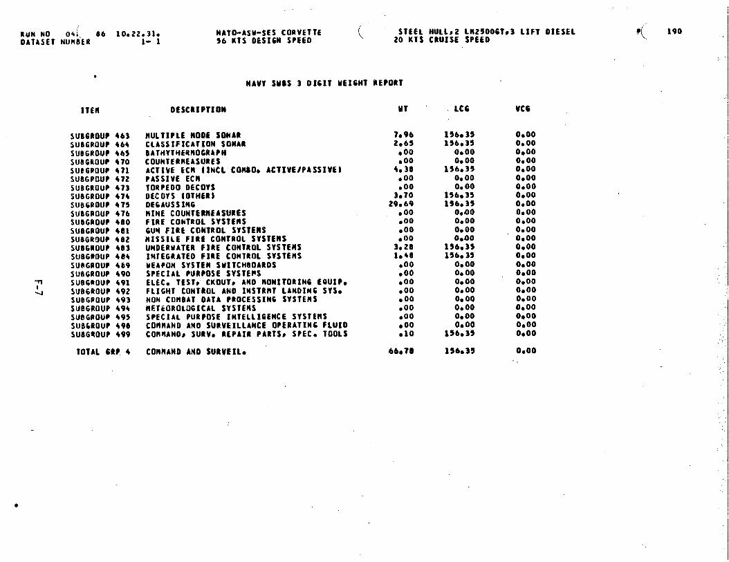
RUN NO 04,, 86 10*22.3I*DATA SET NUM8ER 1- 1
●
sUBGROUP 463SUBGROUP +6+SUBGROUP 465SUBGROUP 470sue6110uP 471SUBGPOUP 472SUBGROUP 473SUBGROUP 474SUB6ROUP 475SU06ROUP 4?6SUBGROUP 480SUBGROUP 401SU9GR!IUP 462SUBGROUP 483SUBGROUP 404SU8GROUP 469SUBGROUP 490
~ SUB6ROUP 491-J SUB6ROUP 492
SUBGPOUP 493SUB6ROUP 494SUBGROU@495suB6aouP 490SU8GQOUP 499
TOTAL 6RP 4
NATO-ASM-SES CORVETTE ( STEEL HUI.LS2 LH2500GTs3 LIFT OIESEL56 KTS OES16M SPEEO 20 KTS CRUISE SPEEQ
MAW SMtS 3 01611 ME1W3 REPO@T
OESCRIPTIOM MT
MULTIPLE ltO~E SONARCLASSIFICAT!iON SONARBATHVTHERROCRAPHCOUNTERMEASURESACTIVE ECH (INCL COHBO~ AC81VE/PASSIVE~PASSIVE ECIITORPEOO OECOYSOECOYS (OTHERI0E6AUSSIN6HINE COUNTERMEASURESFIRE CONTROL SYSTEMS6Uq FIRE CONTROL SYSTEMSRISSILE FIRE CONTROL SWTEIISUNOEUMATER fIRE CONTROL SYSTEMSINTEGRATE FIRE CONTROL SYSTEHSMEAPON SYSTEM SMITCHOOAROSSPECIAL PURPOSE SYSTEPSELECO TEST* CKOUTP AMO HONE?ORING EQUIP.FLIGHT CONTROL ANO INSTRMT LANOIN6 SYSONON COllBAT OATA PROCESSING SVSTENSIIElkOROt061CAL7 $YSTENSSPECIAL PURPOSE INTELL8GEHCE SYSTEHSCOfiHAND ANO SURVEILLANCE OPERATINC FLUIOCORHANOS SURVO REPAIR PARTS$ SPECO TOOLS
COttNANO AND $URVEI1O
T*962.65
●OO,004.30
●OO●OO3.7029*69.00.00●OO.003.281.40
●OO●00●00●00● 00●OO.00boo●10
66078
LCG VCG
156e35156,35
O* 00o* 00
156.350.000.00
156.35896.35
0.4)0O*000,00 .0.00
156.35156.35
0.000.0000000.00O* 000.000.00Oboo
156e35
156.35
0.000.000.00O*00O*OO0.00O*OO0.000.00O*OO0.00O*OO0.000.0000000.000,000.000.000.000.000.00O*OOOboo
O*OO
..
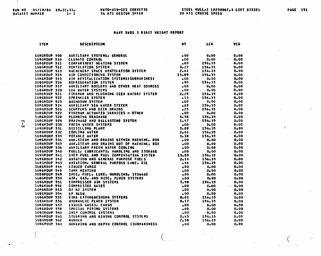
RUN NO 0+118166 10.22031wOATASET NUM(IER 1- 1
ITEM
SU8GRtNJP 500SUBGROUP 510SUBGUOUP 511SUBGROUP 512SUBGROUP 513SUBGROUP 514SUBG@OUP 515SUBGROUP 516SUOG?OUP 5175bB6RouP 520SUBGROUP 521SUBGROUP 522SUBGROUP 523SU@GROUP 524SUBGROUP 526SUBGROUP 527SUBGROUP 528
~ SUBG@OUP 929
03 SUf16POUP 530‘SUBGROUP 531
SUR6UOUP 932SUBGROUP 533SUBGROUP 934SUBGROUP 935SUBGROUP 536SU86ROUP 5+0sueGeouP 541SUBGROUP 5+2SIJOGIfOUP 943SUl!6ROUP 544SUBGROUP 545SU86ROUP 549SU6GROU? 950SUBGROUP 551sua6RouP 552su@6RouP 553SUB6ROUP 554SU86ROUP 5s5SU6G@OUP 556SUEIGROUP 557SUBGROUP 5S8SU6GROUP 560SURGROUP 561SUBGROUP 562SUBGPOUP 563
NATO-ASM-SES CORVETTE STEEL HULLS2 LR2SO06TS3 LIFT OIESEL56 KTS 0ES16N SPEED 20 KTS CRUISE SPEEO
PAGE 191
DESCRIPTION
AUXILIARV SVSTEltSSCLIMATE CONTROL
MAW SUBS 3 OICIT UEIGNT PE?ORT
GENERA1
COHPARTflENT HEATING SYSTEMVENTII.ATION SrSTE!lRACHINERY SPACE VENTILATION SYSTEMAIR CONDITION1N6 SYSTEMAIR REVITALIZATION SYSTERSISUOHARINEStREFRIGERATION SYSTEWAUXILIARY BOILERS AND OTHER HEAT SOURCESSEA MATE@ SYSTEMSFIREMAN ANO FLUSMIN6 (SEA MATER) SYSTEMSPRINKLER SYSTEMUASMDOMN SYSTEtlAUXILIARY SEA MATER SYSTEflSCUPPERS AMO OECK ORAINSFIREHAN ACTUATEO SERVICES - OTHERPLUMBING 0RAINA6[DRAINAGE AND BALLASIIN6 SYSTEMFRESH WATER SYSTENSDISTILLING ?l.ANTCOOLING MATERPOTABLE uATERAUXOSTEAK ANO ORiINS UXTHIN #AC141NE* BOXAUXOSTEAH ANO DRAINS OUT OF RACtlINEO BOXAUXILIARY FRESH MATER CODLIN6FUELSC LU6RICANTSS HANOLIN6 ANO STORA6ESHIP FUEL AND FUEL COMPENSATING SYSTEMAVIATION AND GENERAL PURPOSE FUELSAVIATIONp GENERAL PU@POSE LUSEa OILLIQuIO CARGOTANK HEATIM6SPECO FUELS LUBEO HANDLIN6p STOUA6EAIR~ GAS~ ANO MISC. FIUIO SYSTEHSCORPRESSEO AIR SYSTEMSCOtlPRESSEO 6ASES02 N2 SYSTEM1P BLOWFIRE EBTtN6UtSMING SYSTEMSHYDRAULIC FLUIO SYSTEIILtOUIO GASESO CAR60SPECIAL PIPING SYSTEMSSHIP CONTROL SYSTEHSSTEER!N6 AND DIVING CONTROL STSTEHSRUODERHOVERING ANO DEPTH CONTROL [SUBMARINES)
MT
● 00●oo●65
3,272*61
15009● 00●9O●oo● 00
2.29●13boo.65●25●00
4.581.47
● 00%8820613030
●OO● 00●00●OO
13.052*1+
●+4●00● 00b00● 00
7.98●OO●oo● 00
0.839017
●OO●OO●00
2.452.58
●OO
LCG
Oeoo0,00
1S6S35156.35156.35156*35
0,00156035
0.000.00
156.35196.35
0.00156*35156.35
O*OO156s35156.35
O*OO156*35156,35156G3Y
0.00o* 000.000,00
156.35156.35156.35
o* 000000o* 00o* 00
136.350000o* 000.00
156035156.35
0.000.000000
156.35156.35
0.00
Vce
0.000.000.00O*OOo*000.000.000.000.000.00O*OO00000.000.000.00O*000.000.00O*OO09000.000.000.000.000,000.000.000.000.000.000.000.000.00O*OO0.000.000.000.000.00O*OO0.00O*OO0,00O*OO0.00

/PuN NO d~.i8/66 10.22031o NATO-ASU-SES CORVETTE [DATASET NURRER 1- 1 56 KTS DESIGN SPEED
STEEL Hu1L02 LM2500GTp3 LIFT OIESEL20 KT$ CRUISE SPEEO
SuSuSu
;:SuSuSUSuSuSuSuSu
;:Su
~
m ::, Su
SuSuSuSuSuSuSUSU
;:Su
ITEM
16ROUP 564IGOOUP 56516ROUP 566)6ROUP 567lGROUP 568IGROUP 57016ROUP 571IGROUP 572)6ROUP 573IGROIJP 57416ROUP 580IGRoUP 58116ROUP 582lGPOUP 583IGROUP 58416ROUP 58516BOUP 586IGBOUP 587)GaOUP 588)6ROUP 5@9L6ROUP 590lGROUP 591lG@OUP 592IGROU? 59316ROUP 59416ROUP 595IGROUP 59616ROUP 597ICROUP 59016ROUP 599
TOTAL 6RP 5
NAVY SUBS 3 01611 MEICH% REPORT
TRIll SYSTEM 4SUBHARIMES)TRIM ANO MEEL SVSTEtIS {SURFACE SHIPS)DIVING PLAMES ANO STABILIZING FINS (SLID}STRUT ANO FOIL SVSTEMSNAMfUVERIN6 SYSTEMSUNOERMAY REPLENISHMENT SYSTEMREPLENISMNENT-AT-SEA SYSTEMSSHIP STORES AND EQUIPC HANOLXN6 SYSTEMSCARGO HANOLIN6 SVSTEfiSUERTICAL REPLENXSHHENT SYSTERSMECHANICAL HANDLIN6 SYSTEMSANCHOR HANOLIN6 ANO STOUA6E SYSTEMSl100RIN6 ANO TOWING SYSTEllS80ATSt 80AT tlANOLIM6 ANO STOMA6E SYSTEMSRECH, OPERa 000RJfiATEsRAHPsTURNTA8LE SYSELEVAT1N6 ANO RETRACTIN6 GEARAIRCRAFT RECOVERY SUPPORT SYSTEMSAIRCRAFT LAUNCH SUPPORT SYSTEHSAIRCRAFT MANOL1N69 SEllVICIN6 ANO STOMA6EIIISCS MECHANICAL HAND11N6 SYSTEMSSPECIAL PURPOSE SYSTEHSSCIENTIFIC AND OCEAN EN61NEERIN6 SYSOSUItlMER AND OIVER SUPPORT~ PROTECT. SYSOENVIRONMENTAL POLLUTION CONTROL SYSOSUbNARIPE RESCUES SALVA6E~ SURVIVAL SYSOTOUINGBLAUNCHIN6SMANDLIN6 FOR UNOERMATERHANOLIN6 SYS FOR OIVER~ SUBNER. VEHICLESSALVAGE SUPPORT SYSTEMSAUXILIARY SYSTEMS 0PEBATIN6 FLUIOSAIM. SYSTEHS REPAIR PARTS ANO TOOLS
AUXILXARV SYSTENS
MT
g 00●OO● 00●OOSooboo
2*O42*O4
●OO●OO● 00
3*273m27lob3
coo●OO● 00●OO.00.00●OOg 00●OO
2,96boo
2.00● 00●OO
5.56●03
114089
LC6
O*00Oeoo0.00Oe00O*OO0.00
156.35156.35
0,00O*OOo* 00
156s3515b~35156.35
O*000,000.000.000,000.00Oe 0000000.00
196b35Oe00
156.35o* 000.00
15b.3515b.35
156035
VC6
O*OOO*OOO*OO0.00O*OO0.000.00O*OO0.00O*OOOeoo0.00O*OOO*OOO*OO0.0000000.00O*OO0,000.000.000.00O*OOOboo0.000.00O*OO0.00Oboo
0000
~, ;E 192
.
I
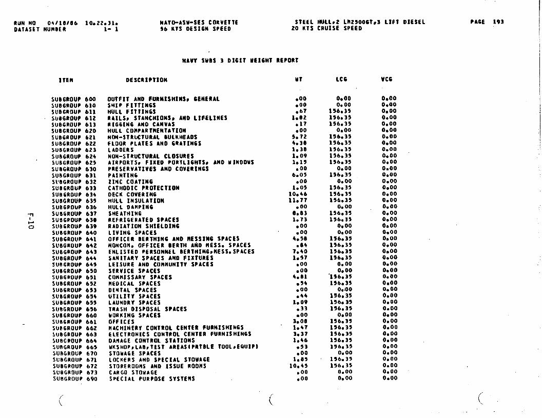
RuN N(3 0+/10106 10a220310DATASET NURSER 1- 1
ITEM
SU06ROUP 600SUB6ROUP 610sue6Roup 611SUS6ROUP 612SUB6ROUP 613SUBGROUP 620SUBGROUP 621SUB6ROUP 622SUBGROUP 623SUB6ROUP 624SUBGROUP 625SUBGROUP 630SUBGROUP 631SllBGRoup 632SUBGROUP 633SUBGROUP 634SUBGROUP 635SUBGBOUP 63bSU86ROUP 637SU86@OUP 630SUBCROUP b3VSUBGROUP 640SUBGROUP 6+1SueGRouP 642
SU8G@OUP 643SU86ROUP 644SU8GROUP 645SU8GROUP 650SUBGROUP 65ASUBGROUP 652SUBGROUP 693SUBGROUP 654SUB6ROUP 655SU8GROUP 656SUBGROUP 660su8G@ouP 661SU@6ROUP 662SUBGROUP 663SUBGROUP 664SUBGROUP 665SURGROGP 670SUBGROUP 671SUBGROUP 672SUBGROUP 673SUBGROUP 690
NATO-ASU-StS CORVETTE STEEL HU1L92 LR29006Ts3 LIFT DIESELS6 KTS DES16N SPEED 20 KTS CRUISE SPEED
DESCRIPTION
OUTFIT AND FIJRNIStllMSC GENERALSHIP FITTINCSHULL FITTINGSRAILSS STANCHIONS ANO LIFELINESRIG61N6 AND CANVASMULL COBPARTRENTATIONNON-STRUCTURAL SULKHEAOSFLOOR PLATES AND 6QATIN6SLADDERSNON-STRUCTURAL CLOSURESAIRPORTS* FIXED PORTLIWTSS AND MINOOMSPRESERVATIVES AND COVERtNCSPA1NTIN6ZINC COATINGCATHODIC PROTECTIONDECK COVERINGHULL INSULATIONHULL 0AtIIPIN6SHEATHINGREFRIGERATED SPACESRAOIATION SHIELOINGLIVIN6 SPACESOFFICER BERTHING ANO MESSING SPACESNOMCOMOOFFICER BERTH AtiO MESS. SPACESENLISTED PERSONNEL BERTIllNGpHESSO SPACESSANITARY SPACES ANO FIXTURESLEISURE ANO COMMUNITY SPACESSERVICE SPACESCOMMISSARY SPACESREOICAL SPACESOENTAL SPACESUTILITY SPACESLAUNDRY SPACESTRASH OISPOSAL SPACESMORKING SPACESOFFICESRACHINERY CONTROL CENTER FURNISHINGSELECTRONICS CONT@OL CENTER FURNISHINGSOARAGE CONTROL STATIONSUKSHOPSLADSTEST- AREAS(PRTDLE TOOLSEQUIP1STOUA6E SPACES10CKERS ANO SPECIAL STOUA6ESTOREROOMS ANO ISSUE ROOMSCARGO STOUAGESPECIAL PURPOSE SYSTEMS
UT
.00●OO●67
1002●17●OO
50724*3Ole381,091*19
● 006.05
●OO1.05
1004611077
● 0000831.73
.00
.004.58
●8+7.401.57
●OO.00
4.81,54●00●44
1.09●33boo
3*O81.473*37lo4b●53●OO
1.8510045
● 00.00
(
LC6
Oeoo0,00
156.35156,39156.35
O*OO156.35156035156035156.35154.39
0.0015b035
0000156.35156.35156.35
0,0015b035156.35
O*000.00
154.3515bc35154.35156.35
0.00O*00
“156.35lSbt3S
o*ioo156,35156.35154.35
0.00154.351S6.35156.35156.35156.35
0,00156.35156.35
0.000.00
VC6
OeooO*OO0,000.00O*OO0.00O* 000.000.000.0004000.00O*OO0.00O*OOO*OO0.000.000,000,000,000.00o* 00O*OOO*OOOeoo0.00O*000.000000O*OOOcoo0.000.00O*OO00000.000,000.00O*OOO*OO0.00O*OO0.000400
PACE 193
(“..
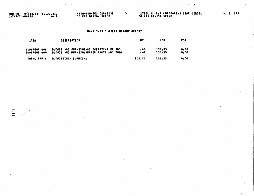
..,
..
.
gCD
u
.-/’
o
oz*
OE
2*
F-n
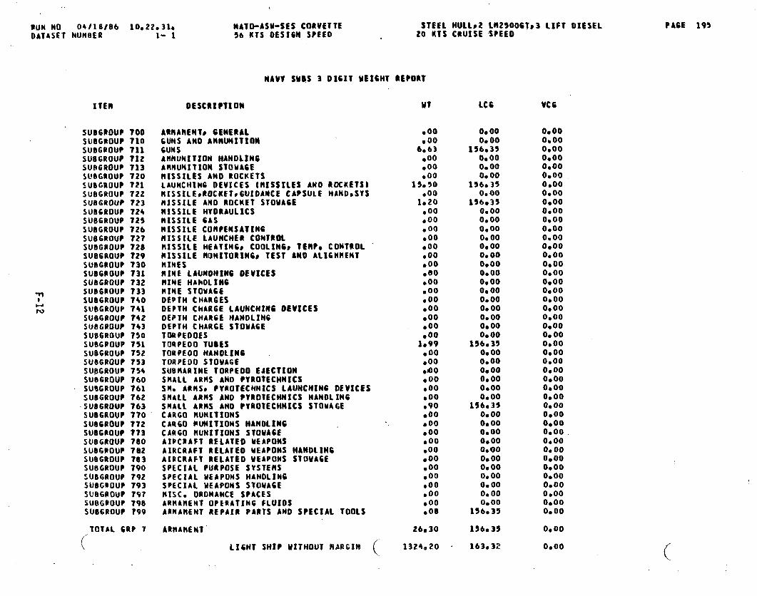
PUN NO 04118/86 1002203IoDAT4SFT NUMBER 1- 1
ITEIII
SUBGROUP TOOSUBGROUP 710SUBGROUP 711SU86ROUP 712SURGROUP 713~~eGaoup 7~oSUBGROUP 721SUBGROUP 722SUBGROUP 723SUB6ROUP 724SUBGROUP 725SUBGROUP ?26SUBGROUP 727SUBGROUP 728SUB6ROUP 729SUBGROUP 730SU06ROUP 731SUBGROUP 732
~ sUB6ROUP 733SU06ROUP 740w
W SUBGROUP ?41SUB600UP 742SUBGROUP 743SUB6ROUP 750SUBGPOUP 751sUB6ROIJP 752SUB6ROU? 753SUBGROUP 754SUB6ROUP 760SUBGROUP 761SUOGROUP 762
SUBGROUP 763SU86ROUP 770SU86ROUP 77ZSUBGROUP 7?3SUBGROUP 780SUBGPOUP 7a2SUBGROUP 783SUBGROUP 790SUB6ROUP 792SUBGROUP 793s~B&@(3up 797SUBGPOUP 798SUB6ROUP 799
TOTAL 6UP 7
(
\
NATCbASU-sES CORVETTE56 I(TS DESIGN SPEED
STEEL MJLLs2 LIlZ5006T~3 LIFT OIESEL20 KTS CRUISE SPEEO
DESCRIPTION
NAVY SUBS 3 DIGIT MEIWT BEPORT
ARllAtlENT# GENERAL6UNS ANO AMMUNITIONGUNSAMMUNITION ttANOLINGAHHUNITION STOWAGEBISSILES AttOROCKETSLAUNCHtN6 DEVICES (MISSILES ANO ROCKETS}HISS11EPROCKET,6UIDANCE CAPSULE HAND,SVSHISSILE AND ROCKET STOWAGEMISSILE HYDRAULICSMISSILE GASMISSILE COMPENSATINGMISSILE LAUNCHER CONTROL)IISSILE MEATIN6s COOIINGS ?ERPo CONTROLMISSILE llt3NITORiNGS TEST ANO AL16NHENTHINESRIME LAONOHIN6 OEUICESRIME HAhOLIN6PINE STOUAGEDEPTH CHAR6ESDEPTH CHARGE LAUNCHING DEVICESOEPTH CHARGE HANDLINCDEPTH CHARGE STOUACETORPEDOESTORPEDO TUDESTORPEOO HANDLINGTORPEDO STOWAGESUBAARINE TORPEDO EJECTIONSMALL ARMS ANO PYROTECHNICSS% ARHSS PVROTECNNICS lAWCHINC DEVICESSNALL ARMS ANO PYROTECHNICS HANOLINGSHALL ARMS ANO PYROTECHNICS STOUA6ECARGO IIUNITIONSCAU60 PUNXTIONS HANDLINGCAR60 RuNITIONS STOUASEAIPCRAFT RELATED UEAPONSAIRCRAFT RELATED uEAPONS HANDLINGAIRCRAFT RELATED UEAPONS STOWAGESPECIAL PUtPOSE SYSTEMSSPECIAL MEAPONS MANOLINGSPECIAL UEAPONS STOUAGEMISC. ORDNANCE SPACESARHAttENT OPERATING FLUIOSARMAMENT REPAIR PARTS AND SPECIAL TOOLS
ARnAMENT’
LIGHT SH~P WITHOUT PIAEGIN (
UT
●OO● 00
6.63●OO●OO●OO
15.50●OO
1*ZO.00●OO, 00●OO.00●OO●OOseo●OO.00●OO●OO.00.00●OO
1.99●OO,00●00coo●OO●OO●9O●OO●OO●OO●oo●00●oo●OO.00●OO.00boo●08
26.30
13Z4.20
LC6
O*00o* 00
156*35O*OO0,000.00
156*35O*OO
156.350.000.000.000.00O*000000O*OOo* 00o* 000.000.00O*000.000000O*00
156.3500000.00O*000.00O*OOo* 00
156.350.000.000.000.000.00O*00o* 000.00O*OO0.000.00
156035
196035
163,32
Vc6
o* 000,000,000.000,000.00O*OO0,000.000.000.00O*OO0.000.000.000.000.000.000.00O*00O*OO0.000,000.00O*OOO*OO0.00O*OOO*OO0.00O*OO0.00O*OO0.000.00.0.000.000.000.00O*OOO*OO0.00O*OO0.00
O*OO
0.00
PAGE 195

. .
(Buti NO 04rtd/Ob IOO22O31OOATASET NURBER 1- 1
ITErI
SU06ROUPmoosua6uouP N1OsuBGtouP nllSU06ROUP nlzSU8GROUP R20SUBGROUP H21SU86ROUP H22SUB6ROUP N23SU6G80UP n24SU8GQOUP M25SUBGROUP H26SU86ROUP R30SUBGROUP 1131SUB6POUP P32SUBGROUP N33
-n SUBGROUP M36SU06ROUP h35
Lw SUD6POUP R36
SUB6ROUP h40SUBGROUP 11+1SUBGROUP M42SUBGROUP H43SUB6ROUP N44SUBGROUP M45SU@G@OUPM46SUBGROUP n47SUBGROUP B40
TOTAL 6RP R
NATO-ASU-SES CORVETTE56 KTS 0ES16N SPEEO
STEEL HULLS2 LM25006Ts3 LIFT OIESE1.20 KIS CRUISE SPEEO
NAVY SUBS 3 01611 UE16HT REPORT
*OESCRIPTION UT
MARGINSCONTRACTOR COHTROLLEO MARGINSOESIGN ANO WILOIN6 HAR61NBUILOIN6 RA#GIN (RESERVEOF60VT0 CONTROLLEO MARGIN [SURFACE SHIP)CONTRACT 0ES16N HARGIM (SURFACE SHIP)CONTRACT ROOlfICATION NARCIN {SURF*SIIIPI6Fll HAR61N tSURFACE SHIPIFUTURE 6ROUTH IIAR61N (SURFACE SHIP)SERVICE LIFE RARCIN (SURFACE SHIPINUCLEAR NACHINERV NAR61N (SURFACE SHIP)GOUT* COhTROLLEO tlAR61N STATUS (SUBS}CONTRACT DESIGN IIAR61N (SUBMARINE)NAVSHIPS OEUE1OPMENT RAR61N [SUBS)NUCLEAR MACHINERY NAR61N (SUBS)FUTURE 6ROMTM HARCIN (SUBMARINE)STABILITY LEAD STATUS ISUBMARINE)TCIRMIN6 LEAD STATUS {SU9HARINES)BALLAsT STATUS (SUBHARINEBLEAOS INTERNAL iSUBMARINEBLEAOS EXTERNAL (SUBMARINES)LEADs HOT [SUBltA@INESlSTEEL~ INTERNAL ISUBMARINEBSTEELS EXTERNAL ISUBRARSMEBSTEEL) RBT ISUBHARINE)LEAO CORRECTIONS RBT {WOS)LEAO CORRECTIONS OTHER THAN I19T (SUBS)
MARGINS
LIGHT SHI? MITH NAR61N
.00●00●OO●OO
171.76●00●OO●OO●OO.00.00●OO● 00● 00● 00●OO●OOb 00● 00600●OO.00●OO.00● 00goo● 00
171o?6
1495096
LCG
O*OOOenoO* 000.00
156.390,000.000.00o* 000.000,000s 00O*OO0.000.00Ob 000.00o* 0000000.00O*43OO* 000,00OeooO*OOOb 00O* 00
156-35
162e52
L . 196
VCG
O*OO0s00O*OOO*OO0.00Oboo0000O*000,000.00O*OOO* 000.000.000,00o@00o* 00O* 00O*OO0.00Oe000.000.000.00O*OO0.000000
0000
0.00
I

RUN NO 04t18106 10e22e31e NATO-ASW-SES CORVETTE STEEL tIUL1S2 LR25006Ts3 LIFT DIESELOAIASET NUMBER 1- 1 %6 KTS DESIGN SPEED 20 KTS CRUISE SPEEO -
NAVY SUBS 3 0161T WEIGHT REPORT
ITFH
SUBGROUP FOOSUBGROUP FloSUD6ROUP FllSUBGROUP F12SUBGROUP F13SUB6ROUP F14sU86ROUP F15SUB6POUP F16SUBGROUP F19SUBGROUP FZOSUBGROUP F21SU8G@OUP F22SUBGROUP F23SUBGROUP F24SUBGROUP F25SUBGROUP F26
~SUBGROUP F29SUBGROUP F30
-& SUBGROUP F31
SUBGROUP F32SUB6POUP t33SUBGROUP F39SUBGROUP F40SUBGPOUP F41SUBGROUP F42SUBGROUP F*3SUOGROUP F*4SU66BOUP f45SUBGROUP F4bSU9GROUP F49SUBGROUP F50SUB6ROUP F51SUBGPOUP F52SUBGROUP F53SUBGROUP F54SUBGROUP F55SUfIGROUP F56SUBGROUP F59SU8GPOUP F60SUBGROUP F61SUBGQOUP F62SUBGROUP F63SUBGROUP F64SllBCpo(Jp F65
SUBGROUP F66
(
DESCRIPTION
LOAOS (FULL LOAD COMDITION1SM[P FORCES ARPHIB FORCE~ TROOPSS PASSENSMIP$ OFFICERSSHIPS NONCOI!NISSIONED OFFICERSSHIPS ENLISTED HENMARINESTROOPSAIR UIN6 PERSONNELOTHER PERSONNELMISSION RELATEO EXPENOA8LES AND SYSTENSSHIP ANMUNITION tFOR USE OY SHIPtOROINANCE OELIVEUY SYSTEMS ABfiUNITIONOROINANCE OEIIVERY SYSTEltSORDINANCE REPAIR PARTS (SHIP AHRO)080, REPAIR PARTS {OROO OELIVO SYS.AMIIO)ORDINANCE OELIVERY SYSOSUPPORT EQUIP.SPECIAL HISSION RELATEO $YSO EXPENDABLESTORESPROVISION ANO PERSONNEL STORESCEMERAL STORESMARINES STORES (FOR SHIPS COHPLEllENT)SPECIAL STORESFUELS ANO LUBRICANTSOIESEL FUELJP-56AS011NEDISTILLATE FUELNAVV STANDARD FUEL OIL (NcSCFOO.)LU8RICATIN6 011spEcIAL FuELs ANo LuSR#cAMT$LIfAUXOS ANO 6ASES (NON-FUEL TYPE)SEA MATERFRESH WATERRESERVE FEEO UATERHYORAUI.IC FLUIOSANITARY TANK LIOUIO6AS ( NON-FIJEL TYPE}#lISCO LIQUIDS IRON-FUEL TYPEICAR60CARGOS ORONANCE~ oRONAHCE OELIVERY SYSCCARGO* STORESCARGO~ FUELS ANO LUBRICANTSCARGOt L1QU1OS {NON-FUEL TYPE} ‘CARGOS CRYOGENIC ANO LIOUIFIEO GASCAPGOs AMPHIBIOUS ASSAULT SVSTEtlS
(
MT
● 00● 00
2.33●74
8.34●OO●OO●00●OO.00
24a900.69
22,30●00●00● 00● 00● 00
00421,89
●OO● 00●oo
2?6.9243,60
.00●00●OO
10.98●OO●OO●OO
3.401.0010001.85
●OO.00.00.00.00●00.00●OO.00
LC6
0.000.00
156.35156.35156.3S
0.000.00o* 00O*OO0.00
156.35136,35156033
O*OOO*00o* 0000000.00
156035156.39
O*00O* 000000
156035156035
0.0000430
. O*OO156035
0.000.000.00
156.35156.35156*35156,35
0.000.000.000.000.000.000.000,000.00
VC6
O*OO0.0000000.0000000.000000O*OO0.00O*OO0.000,000000O*OOO*OO00D0O*OOo* 00O*OOO*OO0.000000O*OOO*OO000000000.00O*OO00000.0000000.000000O*OO0.00O*OO0,000.0000000.000.000,000,000.000.00
.
PA6E 197
.,
(.
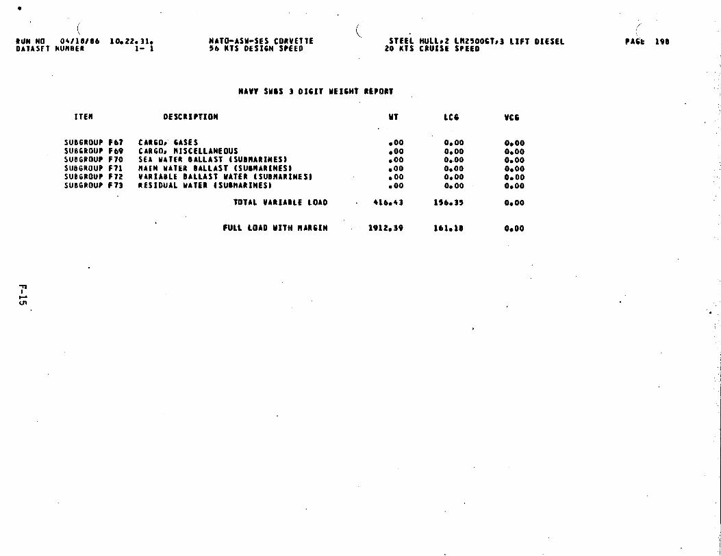
RUN NO 04/18086 10.22.310OAIASFT NUN6ER 1- 1
( ( .NATO-ASU-SES CORVETTE56 KTS OESICN SPEED
ITEM
SUBGROUP F67SUB6ROUP F69SUBGROUP F70SUB6ROUP F71SUBGROUP F72SUB6ROUP F73
NAW SUDS 3 DIGIT ME16HT R~POBT
STEEL HuLL*2 Ll12500CTp3 LIFT DIESEL20 KTS CRUISE SPEEI)
OESCRIPVXON MT
CARGOS GASES ● 00CAR60P MISCELLANEOUS *OOSEA MATER BALLAST ISUBMARINES) ● 00HAIN MATER BALLAST (SUONARINES) .00VARIABLE BALLAST MATER (SUBNARINESJ ●OORESIDUAL MATER (SUOHARINES) ● 00
TOTAL VARIABLE LOAD . 416043
FULL LOAD MITM MARGIN 1912.39
lCG
0.000.000..000.000.000.00
156.35
161018
VCG
0000O*OO0,00O*OO0.000,00
0.00
0000
●
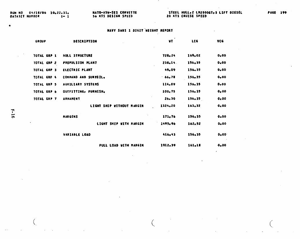
awl No 04/10/06 10022031oOATASET NUH8fR 1- 1
●
6ROUP
TOTAL GRP 1
TOTAL GRP 2
TOTAL 6RP 3
TOTAL 6RP 4
TOTAL GRP 5
TOTAL 6RP 6
TOTAL 6RP 7
NATO-ASU-$ES CORVETTE STEEL MULLS,2 LMzsO06T03 LIFT OICSEL56 KTS OESIW SPEEO 20 KTS CRUISE SPEECI
NAVY SUBS 1 OIHT’MEIWT REPORT
DESCRIPTION Ml -
HULL STRUCTURE
PROPULSION PLANT
ELECTRIC PLANT
COMMAND AltO SURVEILS
AUXILIARY SYSTEM
0UTFITTIN6C FURNISM~
ARMAMENT
LIGMT SHIP MITHOUT RARGIN ,
720.24
238.1+
49,09
“ 66.78
114.89
100075
26.30
1324.20
MARGINS 171076
LIGHT SHIP UITM HARC2N 149%96
VARIABLE LOAD 416.43
FULL LOAD MITtl RARCtN 1912.39
(..
LC6 VCG
169.02
156e35
196.35
1S6.35
156e35
156035
156Q35
163.32
156s35
lb2e52
156s35
lblo18
0.00
O*OO
0,00
0,00
O*OO
0.00
Oeoo
0.00
0,00
O*OO
0000’
O*OO
PACE 199

.. . . . ... .. . . .. . .:,,, . . . . ...’
APPENDIX G
AREA/VOLUME SUMMARY.-)
J’
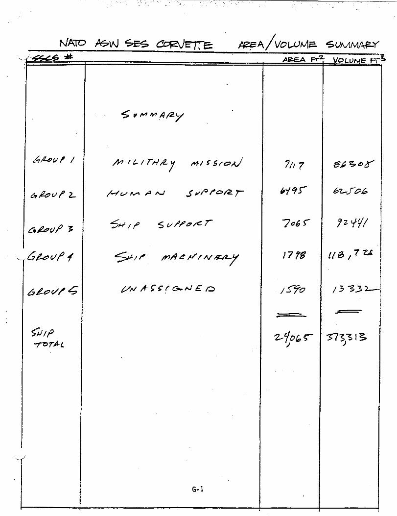
G-1
706 r
,7ZX
33 Z==
-—

.
G-2. .
975
I
-.
em%
I
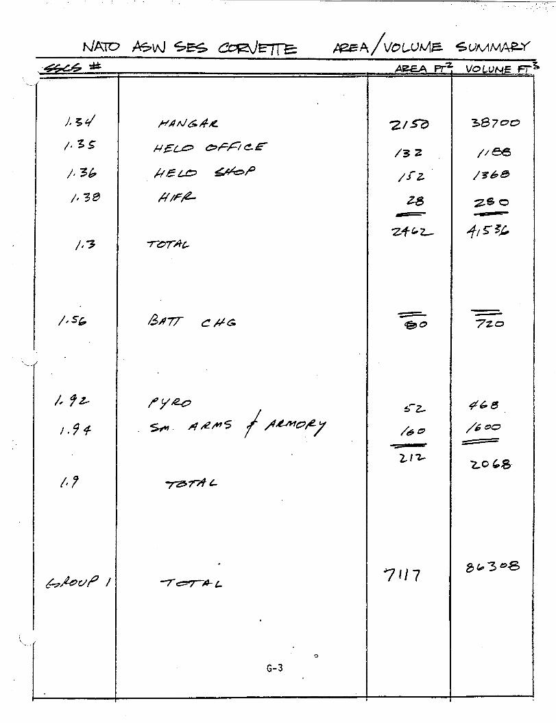
.
‘---
1
C/#&
/
.
()
G-3

.
Z,)iz, !1
2,/z
2, i3
z, /q
2. /
z, ZI
ztz/
q, Zz
zta3
z. z
Z&o
%8
*f
~oB
3Z
Z3*
/“00
#
.4”
G-4
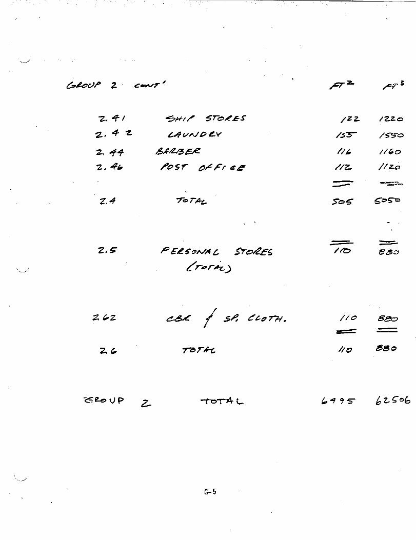
4
. .. . “,, .
285
“’d’
.’
0+=-7’3
/zzo
/s0
//63(3
// 222
.-/
G-5
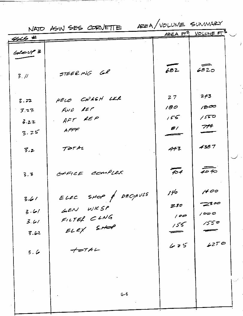
+77A +-
G-6 -J._.,”
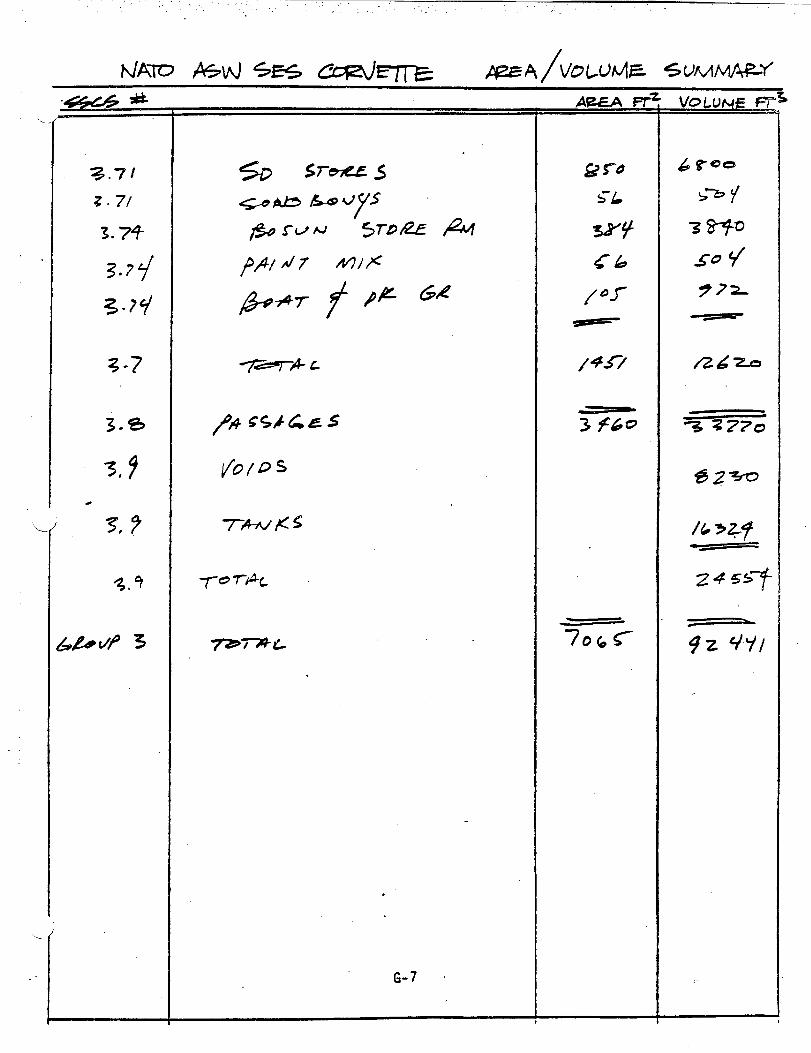
,.. ,.. . .. . .‘. ,,’
%.7’1
z.7/
3.74
3.7q
3.?y
3-7
3.s
3*9
. .‘L
AE&4 I+
5-L

?3
33
7r7m-c
.
G-8
378
/4
J
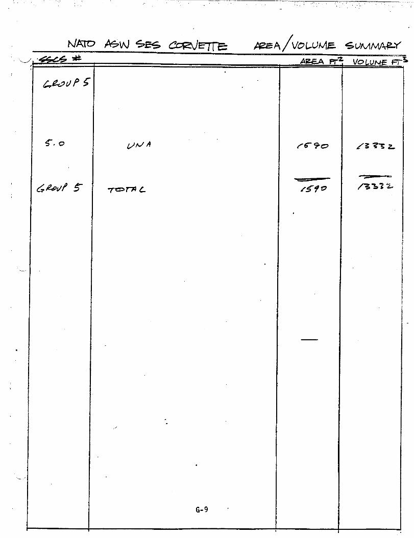
...
.-/
g#zAJP 4
7-?= L
.
G-9 d
AE?LA H

=_-/
APPENDIX H
BELL-TEXTRON REPORT
●

.,
A!!DPROPELLER DESIGN
FOR!fE3iU!-DISPLACE~lE?,TSURFACE EFFECT SHIP
1500 LONG TONS
CO?7RACT NCO024-7S-C-5034
Repo~t 7593-950002
Nell’ez3er30, 1981
. .
..4
-J.
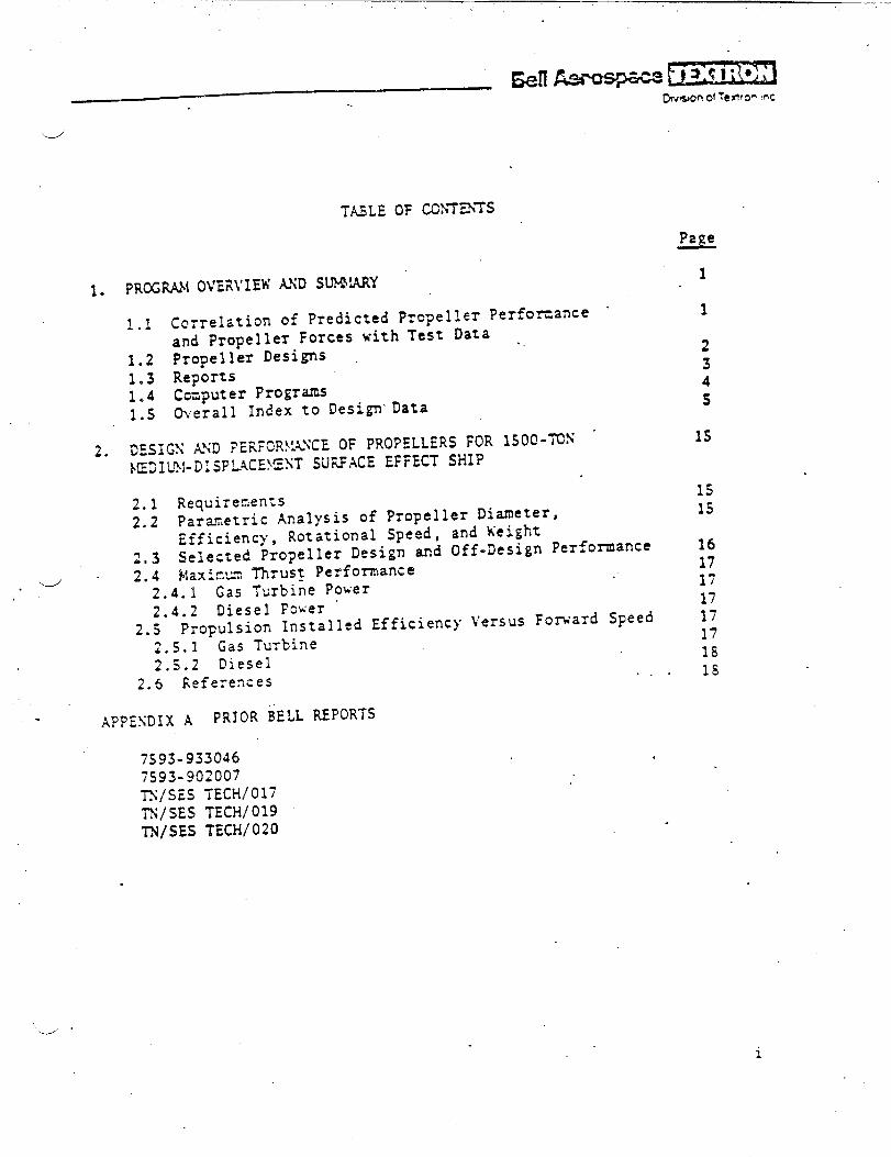
.
. -
-.
1..
2.
.
T.ULE OF COhT==
1.1 Correlation of Predicted Propeller Performance “and Propeller Forces with Test Data .
1.2 Propeller Desi~s1.3 Reports1.4 Cczputer Progrms1.S Overall Index to DesignData
05SIGS ANI ?ERPOR\:\NCEOF PROPELLERS FOR lSO@-~S ‘NZDIL?l-DISFL4C=ST SURFACE EFFECT SHIP
2.1
2.2
2.32.4
-L
RequirenenZSParametric Analysis of Propeller Diameter,Efficiency, Rotational Speed, and XeigF,t
Selected Pzopeller Design and Off-Design PerformanceMaxir.u.nThrust Perf’om~ance
.4.1 Gas Turbine Power2.4.2 Diesel Fwer ‘
2.S Propulsion Installed Efficiency k’ersusFomard Speed2.5.1 ‘Gas Turbine2.5.2 Diesel
2.6 liefere~ces. . .
~pp~IJ)~x A PRIOR BELL REPORTS
7S93-9330467593-902007Ts/sEs TEcH/o17TN/SES TECH/019TN/SES TECH/020
1
1
234s
15
1s15
1617171717171818
.
_. .
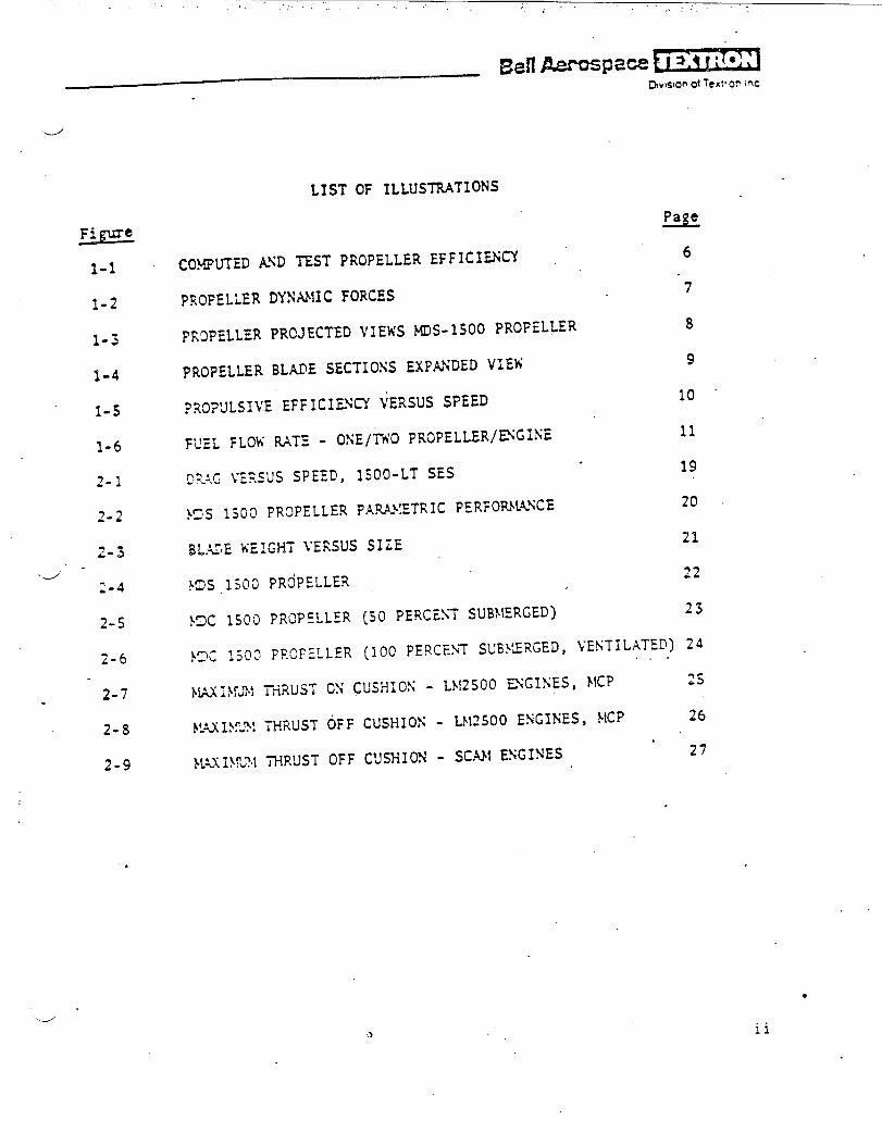
,. –’.,.. . .. . ,...“ ,: .’. .,
EE=1-1
1-2
1-5
1-4
1-s
1-6
2-1
2-2
2-5
i-6
2-7.
2-8
2-9
LIST OF ILLUSTRATIONS
Page
COMPUTED AND TEST PROPELLER EFFICI~~6
PROFELLER
PR9PELLER
PRoPELLER
DYXANIC FORCES“7
PRCJECTED VIEWS MDS-1500 PROPELLER8
BLADE SECTIONS EXPANDED VIEW 9
?ROF’JLSIJ’EEFFICILN~ ~ERSUS SPEED10 “
FUEL FLOW RATE - OSE/Tl’OPRCPELLER/=GINE11
D~-:,GyERSUS SpEED, lSOO-LT SES19
}!2S1500 PROPELLER P.AU}TZTRICPERFO~l&NCE20
BL.tiIEKEICHT VERSUS SIZE21
}!3S1300 PROPELLER22
KIC 1500 PROPELLER (SO PERCE>T SUBNERGED)13
}!2C1500 FF.OPELLER(100 PERCE>T SUB}’JRGED,VE~TIL~T:D~ 24
I@Jl}fm! TFN.USTOX CUSHIOS - LN2500 EXGNES, NICP2s
1$315?.?!THRUST OFF CUSHIOS - L}12500ENGINES, MCP26
WXIIUI THRUST OFF CUSHION - SCAN ENGINES27
.
.--’
ii

LIST OF TABLES
N~.ber=
1-1 KIS-lSOO PRO?ELLER DESIGN AND }lACHISERYPAILAh~TERS “12
1-11 INDEX TO DESIGNS 13..
2-1 XAIY REQUI!?ENE..TSFOR }lDS1S00 PROPELLERS 28
2-11 SEc~Iox oFFsiTs AYD PILA\FOR,~f}~s ljoo PROPELLER
D“I!.!ESSIONFOR 29
‘.>
. . .
.
.
---”
iii

. .
--/’
.
. . .
-,
-“ ‘
7S93-950002

E3eflAercq2aceFi7Ti’T7D.,s,m of le~,.c~ -C
Computer programs were fomulated and used to design partially submergedsuperca~’itatingpropellers (PSCPS). These programs were also employed
to’perform preliminary structural design of the blading and to predict
. propeller off:desi~perfomance over a range of submergence. PropulsiontF,rustwas con?u:ed for installed propellers and was compared to the shipdrag, taking into consideration the propulsion engine characteristics,lesses, and various machinery arrangements. pr~dicted propeller non-
dire~sional characteristics and propeller forces and moments werecozpcted and correlated with test data, in a limited effort.
1.1 Correlation of Predicted Propeller Perforamceand Frcp.ellerForces with Test Data
A critical perfoma~ce correlation was made to validate the off-designper~ormance results of the SSCP computer progrm. This progrm. was used
for most of the off-design performance predictions during this study.T~e corielzt.icn cor.?zredthe cozpzted predictions of the SES-IOOB pro-peller design with model test data and full-scale test data. The results,which were favorable, are contained in TX/SES TEC3d/017of July 24, 19S1,
J figzres 9 and 10. Figure 1-1 of this r,eportis a copy of Figure 9,whichskz..isthe ccnparison of pfedicted and test efficiencies.
.
The work on correlation of computer-predicted forces with model testLaza, xhicb vas inclu~ed in the original task, was deferred after itbecane appz~ent that riexpro?eiler ’designs would b? required .f$.raddi- .tional ship configurations. Before the deferral, computations weremade of both steady and fluctuating vertical and horizontal propellerforces, for the B6620 propeller, which was designed for the 900-longton (LT) gross weight Medium-Displacement Combatant (MDC) SurfaceEffect Ship (S2S). These results were shorn on pages 2-53 through2-S6 of tl-,einitial report of December 1980. Using,the available SSCpcomputer program, detailed time histories of fluctuating forces for thissame propeller were co~puted, as well as the blade loads for various
forward speeds. Both were computed with and without the influence of
cus3ion outflow at the propeller. Computations included shaft inclinationz~,glesof O, S, and 10 degrees. These partially completed dynanic forceresults were presented in the program oveniew in Septenber 1961, and .are sho~m here as figure 1-2. The corresponding influence of cushionflow and shaft inclination on averaged propeller performance is shck-ncr.pages 2-s7 tkiro~gh2-60 of the initial re$ort of December 19S0.
.
Correlation work was completed to describe the geometry of the bladesections and blade planfons of the David TaYIGr Xaval Ship Research in~12e<:elcpnentCenter (DITSRDC) 4281 and 4407 highly skewed propellers;
.-./’
7S93-950002 1

*
13eiI Aerospace k-~hS13n 0! Texttor, Inc
parameters included local skew, thickness, camber, and angle of attach -at several radial sections. This nade possible computerized performance
predictions and force predictions. It was planned to.cmpare predicted.
performance and forces with available model test data, at various bladerakes md shaft inclination angles of the 4281 propeller and the 4407propeller. No conputer nms were made, however, because further correla- “
tion t~rk was deferred by the custuier. .
1.2 propeller Designs ‘.,
Fi\’epropeller designs were pre?ared and investigated. Four of these were
new designs and the other w= an existing design scaled to match the ?4edium-Dis~lacenent Surfzce Effect Ship (MDS) thrust and power requirements.
These designs were made for various SES vessels, which ~ere studied by the
XaYy as follo~s:
a. coastal SE’S,400-LT, full-load displacement
c. t4ediur,-DisplacementConbatant SES, 1600 LT
“d. \fe~~~~.-Displacement Combatant SES, 1600LT (s~]ed SES.1OOB../”
propellers)
e. Mediun-Displacement SES, 1500 LT.
lTfieCoastal.SES propeller is a fixed-pitch design; allcontrollable-pitch propellers. Ship drag was suppliedFigures 1-3 and 1-4 show various views of the HDS 1500table 1-1 Iists the design and machinery paraiieters.
the otkers zre .by the Sa~y.propeller, and
The off-design characteristics of the Propellers Qere computed and matc~.edto a
●
●
●
●
●
variety-of,rachinery
Coastal SES: CODOG
MDC 900: COD14G
!4CD1600: (a) CODOG
. .configurations for the various vessels as follo;rs:
and [b) only two gas turbines
Mls 1s00: (a) two gas turbines or {b) CODOG.
The gas turbine used for the sriallesttwo ships was the .411ison57@K.+jfcrthe larger SES, t},eGeneral Electric (GE) L}!2500was used.
‘d’
7393-9S0002
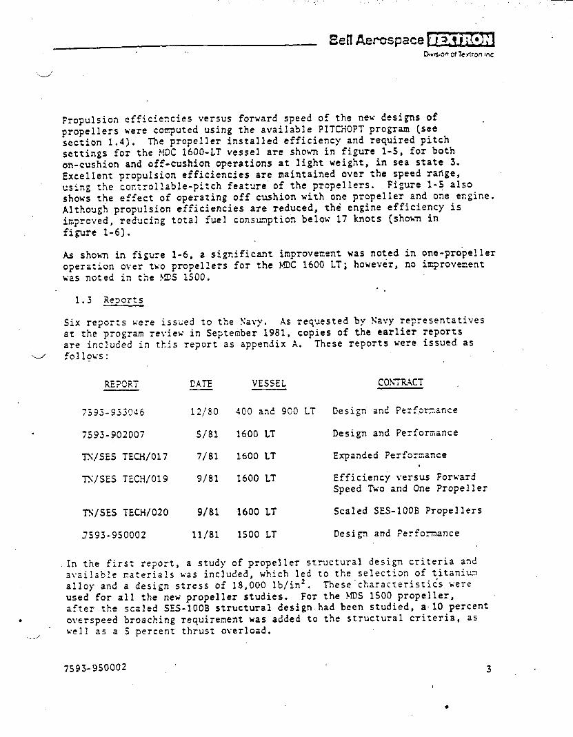
\Sell Aerospace
C%son of Temon mc
.-/
Propulsion efficiencies versus forward s?eed of the new designs ofpropellers were computed using the available PITCHOPT program (seesection 1.4). The propeller installed efficiency and required pitchsettings for the ?fDC1600-LT vessel are shown in figure 1-5, for bothon-cushion and off-cushion operations at light weightl in sea state 3.Excellent propulsion efficiencies are maintained over the speed range,using the coct~oll=ble-pitch feature of the propellers. Figure l-~ alsoshows the effect of operating off c=hion k’ithone propeller and one engine.Although propulsion efficiencies are reduced, the engine efficiency isim?rcved, reducing total fuel consunptiotibelow 17 knots [shown infi5wre 1-6).
M shokm in figure 1-6, a significant improvement was noted in one-pro~elleroperation over two propellers for the MDC 1600 LT; however, no ixcprovenentwas noted in the }!DS1500.
“.1.3 Re?orts
Six reports sere isszed to the !iavy. AS requested by Xavy representativesat the program review in September 1981, copies of the earlier reportsare included in this report as appendix A. These reports were issued as
““-J follows:
RE?CF.T
7595-933045
. 7593-902007
TS/SES TECH/017
TS/SES TECH/019
T!i/SESTECH/020
.7593-950002
DATE
12/s0
S/81
7/81
9/81
9/81
11/81
In the first report, a study
VESSEL
400 and 900 LT
1600 LT
1600 LT
1600 LT
1600 LT
1500 LT
Design ant?Perf,ac.znce
Design and Performance
Expanded ?erforzance.
Efficiency versus ForxardSpeed Two and One Propeller
Scaled SES-1OOE Propellers
Design and Ferfomance
of propeller structural design criteria andav,zilablerater;als was included; which led to the selection of titanimalloy and a design stress of 18,000 lb/in2. These ”characteristi~s wereused for all the new propeller studies. For the FIDS1500 propeller,.:a.ter the scaled SE.S-1OOBstructural design.had been studied, a10 percent
● overspeed broaching requirement was added to the structural criteria, aswe]] as a j percent thrust overload.
d
7s93-9S0002 3
I
●

. .. . ... . . . . .
1.4 CoEputer Pro~ams
Several computer progrms were used in the propeller desi~ and performance
investigation. They included the following progrms:
SCRP
SSCP
PIT’CHOPT
.
USEs}~!?LEOUTp~
..
Design point Report 7593-933046,Page 2-39, 2-40
of~-design, optimization and .
p=opeller forces
Report 7593-933046,Page 2-41, 2-42, 2-45,2-44, 2-45, 2-46
~!axi~,umthrust versus engine limits} lY/SES TECH/017,
gear ratios and prcpeller pitch table 1
setting
M5W4n.Jrnmropeller efficiency versus TS/SES TECH/019,
OnA winir.lml fuel flOW table 6 ~.L“,=A~81’---r-forward s?..., ...-..-...—. -—— .with one or two engines, consideringengiI?elir.its,pitch settings, andca~itation limits
The SCRP progr=~.Kas derived from the SCPRP progrm listing for design of
supercavitating propellers, which was originally fomulated by Hydronautics
Inc. .The Bell version was reformulated for t~’pewriterterminal controlon an IBN conputer system (rather than card deck control on the Control
Data Corporation system]. This work was described.in the first report. A
listing of the new progrm with someadded features was submitted to the
Navy: the reformulated program exactly reproduced Hydronautics samples.
Bell has proposed changes and additions to this program and its documenta-
tion to overcome certain existing limitations. The program revision would:
a. Eetter define peak efficiency perfo=,ance and face cavitationlimits
b. Modify t3e
to tkle conventional
C. Facilitate
●
skew and rake reference from the blade trailing edge
center chord reference
terminal input
>
jj93-950002
●

‘---’
d. ~cr.~ctenonventilated ?erfomance
e. Doc=ent progrm changes, options,
new listing to the Navy.
1.5 ~erall Index to Design Data
Table .1-11 is an index to the principal desi~- featuresresults for the various propellers.
,.
and furnish a
and performance
. . .
759-3-9S0002

4ulu)wt
1.0
I0.8
(3.4
0.2
c
AT DESIGN BLADE PITCH = 32.74 DEGRCESPARTIAL SUBMERGENCE = 34,5%COMPUTATIONS AT WAKE FACTOR = 0.0% .
ZERO StlAFTANGLENO CUSH1ON FLOW
CUSHION NOT SiMULATED lN MODEL TEST..——-.— .-- .-.-..-1’” ,...-.— .—.- ?- 1 r
‘TT
—-—--------1
.. . .}
i
_—. —.—
——-
—-- -/
J___.0.2
(’
-.
L-......-.
~ 1. _..~ .. . .. . .._..j=jmDELT~
----
7A--– [“““’’””-””I
II
““1
I
..
-----
--.——
“ I l\
.. ---- ‘P‘\...-—II
0.6 - O.H 1*L 1.4 1.64
ADVANCE COEF:i:IENT ~
Figure 1-1 COMIIII”I’I:DANIJTEST PRO1’El,l,l;llI:II:IC1I:NCY SES-100B
I
,,
.
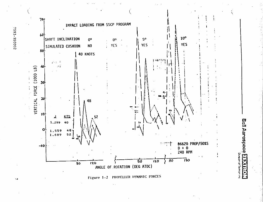
....,
.::...
...
...
..
..,..
.,,
_/
-.
.
------.-
-----------
-------’-
---------
----
-------.-
—---
...----’
-----
.’--
—.-.
—-
-----
.-----
—-
--.---—-
--.——
-----
-----“.
..
.
o=g
.-4
_,---------,.r’+@=’
~+~--—
-../7
—..-..------.
—7 .
......--
----
.2~:;
o*
--—
——
—._—
_,..
..
“a—
——
_,.
;i;—
——
..”
8
——
——
..-.
——
—.
.--—
—
-
‘-4’s
nLi0.
..
----..-.
uJwz
.
.r%
.
0
.
_.—.T.
..
w)
3NOd7V)Ilti3A
--,..
(870001)
.--”.-.
7593-9500027
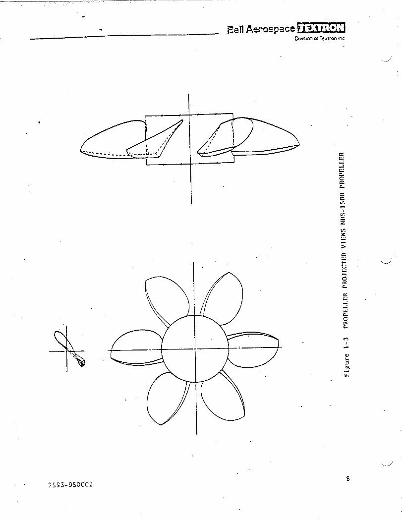
—. —.: ... . . ,,
●
ccL-,
.,
C=&
c...-. ‘u”
ijS3-550002s
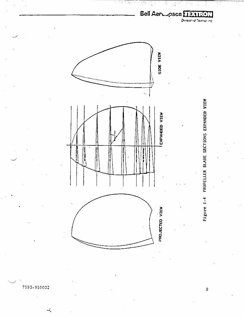
. . . .. .. . . .. ... . . . . ...., .,
Ml Aem+ace ~r~DwIsIOn of Tefiror. Inc
-./J
.
.
‘d “7593-950002
. . I
. . .
9
-.
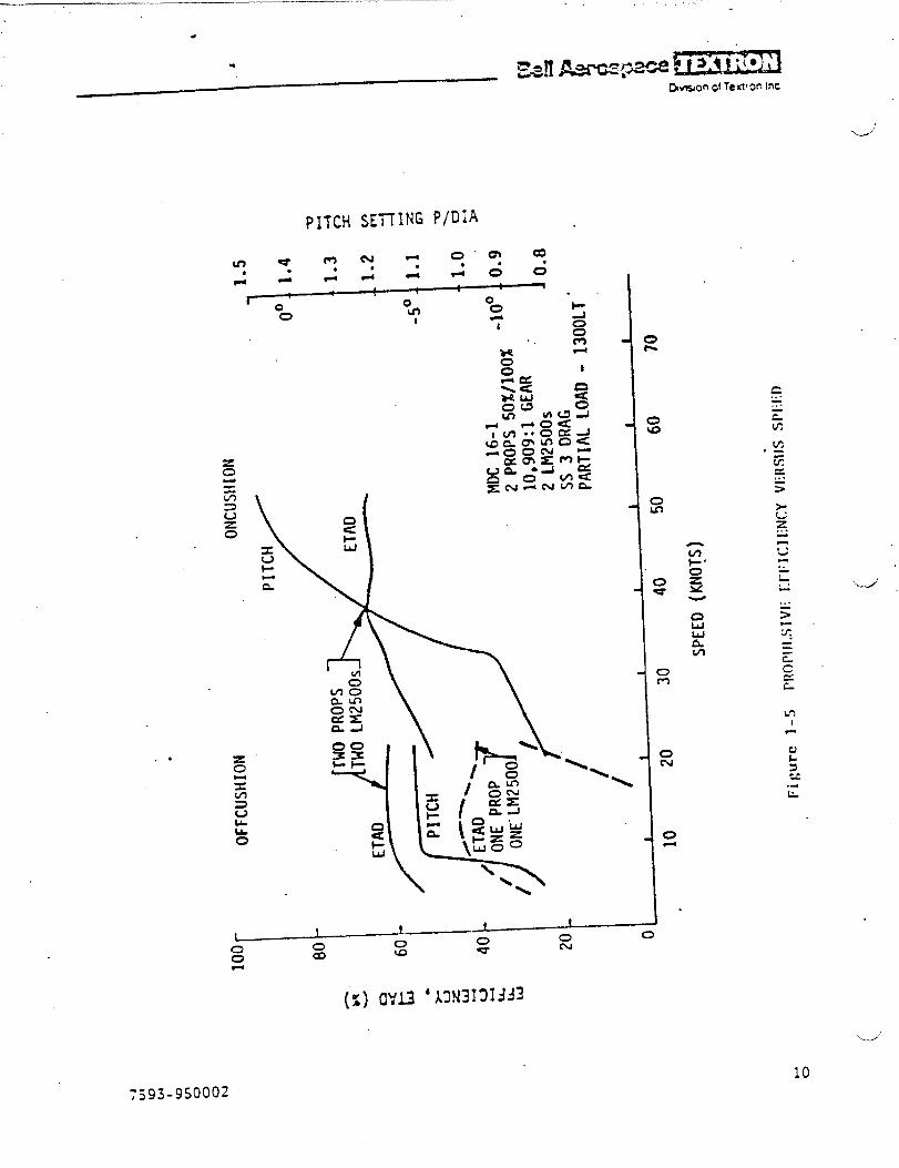
.
PITCH SE~lNG P/DiA
●
Lbo
c...-.zu?
z“-Ln,..5
t.-1
~j93-950002
w“
10
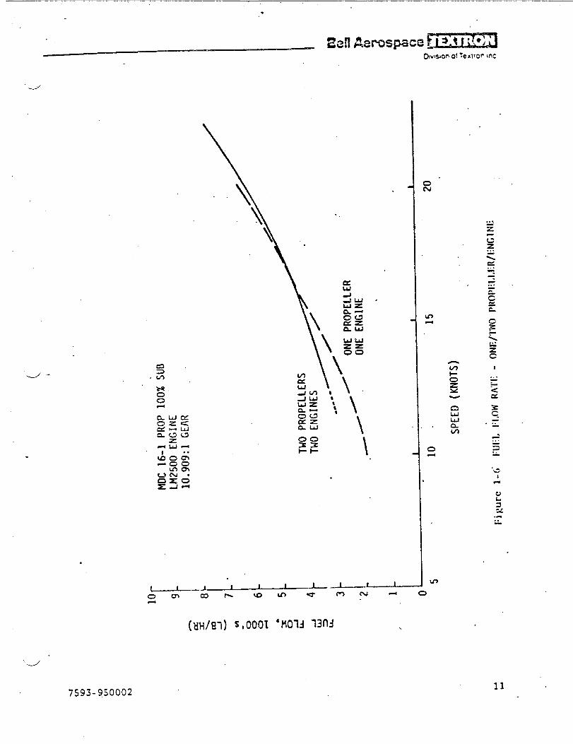
.
IE3iEElMl &?rc#spax31
d
.-./ -
.
-#00
.
.
.
(WS7) s,0001 ‘MO-U 7304 \
7593-950002
o
w
owwnm
I
.. .~-<Ct
11
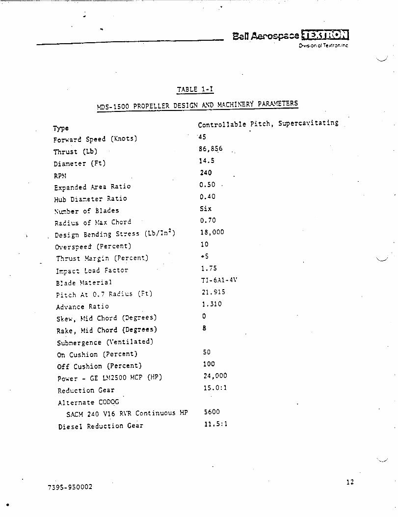
_ .. .. .T.. , ...*
TABLE 1-1
MDS-1500 PROPELLER DESIGN AYD M4CH1SERY PARAMETERS
Type
Forward Speed (Knots)
nTUSt (Lb)
Dianeter {Ft)
RF?!
Ex?mtied Area Ratio
Hub Dianeter Ratio
Sm.ber of Blades
Radius of \!axChord
\ Design %nding Stress (Lb/ln2)
Werspeed (Percent)
Thrust Margin (Percent.)
lr.=c: Lead Factor
Blade }lateria]
pitch At O.? Ra?ius [Ft)
M\’ante Ratio
Skex, }~idChord (!)egYees)
Rake, }fidChord (Degrees)
Su~mergence [Ventilated)
On Cushion (Percent)
Off Cushion (Percent)
Poser - GE L~!2500!4CP(HP)
Reduction Gear
Alternate CODQG
S.4fX240 V16 RJR Continuous HP
Diesel Reduction Gear
Controllable Pitch, Supercayitating
’45
86,8s6 .
14.5
240 -
0.50 ~
0.40
Six
0.70
18,000
10
+5
1.75
TI-6.41-4Y
21.915
1.310
0
8
so10024,000
1s.0:1
S600
11.5:1
w
739S-950002
●
12
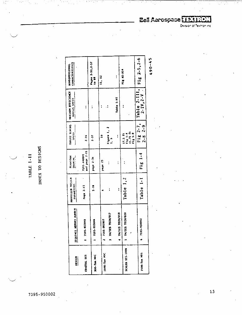
:..,, .’. . . .
‘d
.
.
.
x!..
=
z
\
7395-9S0002
I 1-
1
——
u
t!e.u
I
. . .
../SECTION 2
DESIGX .KNDPERFOQ-~i~.KCEOF PROPELLERS,FO?. 1500-TCX \EDI’J.l-DI SPL.4CE\fE\7
SURFACE EFFECT SHIP
‘4’
,., ..-.,, . .. .. . .. .. .. . .. ... . ......,,. ,’” .“ ,.#
2. DESIGN ART PERFO!WANCE OF PROPELLERS FCR 1500-TOS}EDiLT1-DIS?LACL~lEhTSURFACE EFFECT SHIP
A supercz~’itating,partially submerged, controllable-pitch propeller was .
desigr!edfor the Medium-Displacement SES (NDS] of 1500 long tons (LT) grOss
weight.
The vessel parameters for this study were defined by the Nav}*. Propulsionpoxer xas provided by two General Electric LF12500engines. An alternateconfiguration cor;~inedtwo diesel engines (used for off-cushion propulslor.
only] with the gas turbines (that is, in a CODOG propulsion system.
arrangement].
2.1 Rec;~irenents
y=~~e ~.I lists the basic requirenerttsand engine ratings for the propeller
design. The d=ag cur~’essho%n in figure 2-1 were supplied by the Navy,and a~e based on model test data. In sea state 3, the ship is designed to
o~erate at 45 knots, cn cushion, with a full-load displacement (FLD] of
1S00 LT, and at 20 knots off cushion at the same weight. Alsorequestec?was the on-cushion, top-speed pe?fornance in sea state 3, with
\J’ a 105O-LT displacement.
For t!-.ealternate configuration, SAC!;diesel sngines were selected becauseh+ and suitable power ratingS.O: theii IiSht w~ig,t.
eng
Two SAC\!?40 Y16 RVR
i>e~ xere used, one on each propeller,’and were rated at 5600 metrichcrsepoxer, co~,tinuouspo~er.
Tk.ereduczion gear rztics were to be selected as those necessary to matchthe engines and propellers. ~
2.2 Parametric Analysis of Propeller ”Dimeter, Efficiency,Rotational speed, and Keignt
A parametric analysis was made to size the propellers, using the SCRPconputer program in its preliminary design mode. Diameters from 11 to
17 feet ~ere investigated, at the 4S-knot point, with a design thrust of
67,000 pounds per propeller at 50 percent submergence. A naxin~i ~hrustof 92,000 pounds was input for structural computations and the design
blade stress was 1!3,000lb/in2, using titanium material. This is thesane stress t!-.atxas used for prior designs in this project.
Figure 2-2 shoxs the par~netric results of efficiency versus di=neter.Tae effects of design rpn on efficiency and ?itch are also shown. At e~ck
‘d
7395-950002 15
~n level, the efficiency increases as the diaiieteris increased, until apeak value of efficiency is reached; thereafter, the efficiency declines.
Apro?ellez dizseter of 14.S feet was selected, which was the maximumefficiency that could be obtained without the blades overhanging the side-hull at the trmsm. The selected mopeller has a design point efficiencyof 72 percezt, and a level of 240 ~m was selected.
Fi3zre 2-3 SF,OWSthe effect of diameter on total blade weight. The design
is for six blades Znd, as can be seen, blade weight is almost independent
of rpm. Hub weight [not included here] is expected to constitute most ofthe total p:gpeller ~ei~hte
E~ti~ation Of total propeller weight is planned for the next phase of the
design project. The selected design has a preliminary total blade weightaf about 52S0 ?Qu!?ds.
2.3 Selected Frcpeller Design and Off-Design Perfonance
After the parm.etric study was made to select the design point, final\ design W2S COK?ti~e d with the SCRP program, using the ,sanedesign point
ihrust and “ir,putparameters. (See table 1-1 for the principal propellerdesigx z!??P42cY,inery para~eters.) These values are the chosen inputs tot}.ecar>uter prsgran, except for thrust, pitch, advance ratio, skew, and‘e,rat. which are p~ogrml outputs. The ge~r ratios are found by matching
ezgi?e to Frcpeller characteristics.
Corple:e inpus and OU:?UC data for the design are gi~’enas t“able2-11.T}.e first page of the table is input data and subsequent pages are the.output data. The second page gives overall perforr,ance,with detailedhydrod>mamic and geometric data at se~teralradial stations. The next fourpages show the geoEet~ of the blade sections and planform, and the finaltwo ~zges show the section pressure coefficients End Pressures- Headingsfor the printout colums are defined in reference 2-1. (Section 2.6).
Figure 2-4 shows the projected and side views of the propeller-blade, withthe exparic?edoutline. The txo views are a plot of the geonetric dztagiven in table 2-II, which does not show the blade trailing edge thickness.
.
Figures 2-S and 2-6 give the nondimensional performance of the propellerat 50 and 100 percent su!xner-gence,over a wide rsnge of off-design advanceratios and pitch angles. Values for these plots xere obtained fron theexisting Eell SSCP conputer program. Correlation of the progran’s off-de~ign results with test data is sho~m in the sumary and in the appendix.
“L=”
o
7395-9S0002 16
w

,. —. .. . .,,
d“
2.4 Maximum ~rust performance
2.4.1 Gas Turbine Power
~aximrn thrust versus speed with LV2SO0 power is compared to the drag infigures 2-7 (for on cushion) and 2-8 (for off cushion), with a 15.0:1r~iucticn gezr.
. .Results are o“ctai?ledby applylng engzne arcd propeller
characteristics to the NEWWP computer progrm. Enough thrust is availableat maximum continuous power to operate 1500 tons at S2 knots in seastate 3, and to operate 1050 tons at 57 knots. Therefore, there is a
margin of thrust to operate at 4S,knots at 1500 tons (full load) in seastate 3 at the propeller design pitch. The propeller face cavitationli~it advazce coefficient set to 9S pezcent is shohn in figure 2-7. ‘I%efacecavitation linit shorn was determined by an advance coefficient of 9Spercent of the peak efficiency ad~ance coefficient.
The effect of gear rec?uctionupon mximm thrust performance was studied,using 16.5:1 and 13.O:J reduction gear ratios. .Yaximuinthrusts and fomardspeeds were dscreased xith a 16.5:1 reduction ratio. Maximun thrusts wereincreased using a 13.0:1 gear ratio, hut pro?eller rpm limits were encoun-tered at -lower fowzrd speeds, so that the design was not feasible with
+-/ this gear ratio.
Ki:h alternate diesel pcwer, figure ~-g shows t~e maxinwm thrusts available
for off-c’us?.io.noperation. There is a considerable r.arginin t~trustat20 knots, using the S.401240 V16 R\”Rengines at S6C0 co~tintiozspower afida 11.S:1 reduction gear ratio.
2.5 Propulsion Installed Efficiency Versus Forward Speed
2.5.1 Gas Turbine
Tables 2-III and 2-IV give po~er and propeller parameters for operation insea state 3 with thrust equal to drag at 1500 tons and 1050 tons, respec-ti}fely. The propeller pitch is set for the best performance at each forwardspeed. These tables represent operation with gas turbine limits and a15.0:1 gear reduction ratio.
Table 2-111 S}.OKSthat propulsion efficiency varies from 0.607 at S knotsto 0.711 at 4S kncts for the full-load operation at 1500 tons. Thepropeller pitch is -12.S to -10 degrees off cusSion to on cushion, thenincreasing to +5 de$:ees at a top speed of 50 knots. Above 50 knots,engine rpm, power, and prcpeller overspeed rra limits are exceeded.
.-J
739S-950002 17

At 1050 tons (see table 2-IV),the available drag data only covers on-
cushion performance, starting at 22.5 knots. Proyeller pitch setting
increased from -lo de~ees at 22 knots to +7.5 degrees at 60 knots; above
60 knots, engine power and rpm limits are exceeded.Efficiency Increased
from 66 to 74 percent over the usable speed range. Top speed IS approxl-
. .
nztely 60 knots.
Table 2-v S},OWSthe power and propeller parameters for off-cu~hion operationwith diesel efigines,with thrust equal tO .drag~at 1500 tons, in sea state 3.
.4gain,“propellerpitch is set for.best perfom.ante at each forward speed;
pitch increases from -15 degrees At 5 knots to +2.S degrees at 20 knots.
Propulsion efficiency increases from 0.614 at 5 knots to”O.683 at 13.S knots,
deceasing to 0.608 at 20 knots. Although the propulsion efficiency is not.
chsrged greatly for diesel compared to gas t~bine. ope~?tlonnthe engine
decrezses considerably. T~lcal gas t’uTbineS,.elcor,s~--.ption~?e~~fic ‘-cOns’~.ptionat 20 knots would be 0.70 lb/hp/hr, corpared to 0.40 lb/hp/hr
for the diesel.
2.6 References .
;
‘J
. . .
7-39S-930002
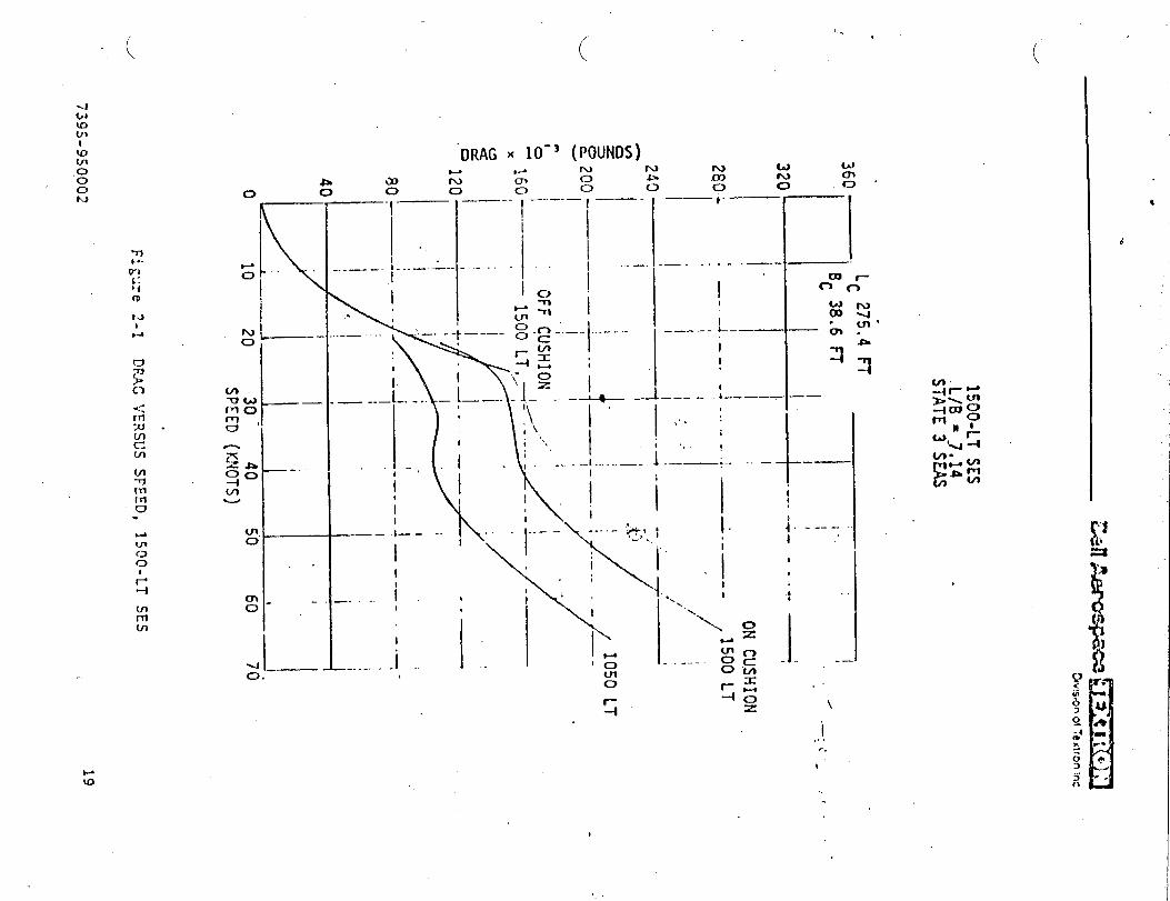
“DRAG X 10-> (POUNDS)
o ——.
I——,.
—.
—-- , _..-.-—-!
.—-. i-..—..L-1
-nP. .+.—. . . . . .—-
la ~
<
- -T1
Io n .------:._.. . —-—. ~-c-.—.
1-—..-L–-—————
;1i\ Ir-~,
11
i-~ i_ --L. ... –.!_—.)1. . --L..+— I——---1-.——), ‘ 1,,:
I i ‘%
I - :.””-. ,- .-1 .. . . .. —-.
j_.. :
—~.. . .— -. ..- ,.
~ I
I1,
iI I
I I
\
----- !~>, ; 1-—.— ---
~ . \* ~
i ‘ - 1“--- ~ ‘[ ~I-. -. i.t ‘ “’
I
I.-..-...;, - ‘o
——
--—m-clm
“3.
—-.
i ----I .’
‘$fA‘5
c)
Iii“. \rn
mLA
--
I
0r--4 \
i.,,r,
t“’
...
,
,,.

—— .-<[ . ..??’:’;:.:::.-:::j,.,.:”””.\””;::\;~””’::.,+.:.::.:... . ;. ..’.,
I.-.
,“. -;’:.-.! : ; .;.:< KT---,;
: ..! “i :“::~:;: ;:. .—
;“ i ><l+o .R++LZL... - -- --—:.. ::: I . . ..’. !:.” -,. —
. . . . . .1. : ..: .
t -— -- —
i ‘--?V” M ‘ ‘--- - ‘-- ----—-~-_--_:- -. ----
:—I — .- —.
.-_- —- .--—.--—- -— --------
--....
—--. .— —
\-. -i ---- –—-/-- - --–\–-”--—-
1.-.....-- -—-——. . .-
\ \I_ , >
_. “{1!F. .._: -WC :~- — .,----.-.I ‘ . 7VELOCITY- 45 KNOTS‘-’! THRLJS~- :;’::: kg:=
—‘L1
‘- ;T’Rki: 18:000 PSI.45: \ d
--- t“. -.“.’....<..~---;:r ; j -~1 &;;:+E~OO’80
\. I— 502 SLJEYIEP.GENCE !
L.. d -.--– ---”-. ---–- ----
PJ*:; ~~ I —— ...-
J{{,,:...li. i i.~1 ..-.—._-. &.._ —-- *----- ----L. .-1 —----– -b~-- -- I— __ .-. ---
{%3 ;++--,.-
\\-;: “-:---”t-”-T””----”-- -----. . .;_~\q.: .......
--~,--- ““__
I \ >U= --- __+.. .-.; . ---- --L.-,$3 - —-- –--—-7-—:’ —“-: -I -%=: I ‘ = ‘&.&__+_&+ ------
. . . .
—
- ----
- ——
k..a G
{:i
ID-H ,2 DIW,EIER (FEET) --~;- --i! --------- .. . ... .—-----
. . ?J.:Gkf—- —
20
“u
w’
..
7j~’j-950002

.’ . ...’. . . . . . . . . ..
... ,
4
w
‘d
4000
.
if‘2 3000L
240{
220C
200(
180(
------=’4+
Y I I 1 I 1 t i
10 11 12 13 14 15 16 17 18
PROPELLER DIAHETER {FT)
..--’ Figure 2-3 BLADE XElGh7 VERSUS SIGE
21
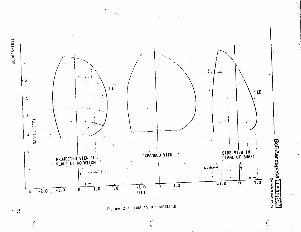
“.“e
“.
.
II !
.,
)
1’\L \/-:\
,r..
I /. ‘‘\-., -
1 /
,: i !-:.4.
.,_
LE
t1/1
..-, ,,“---
i!,
* .-+
. . . . .
.
.*., , .
i.>\
;.● .4
/
.
\
..* \\
)ILE
..L’_.—- !
I
i
I
IIi
““. ,
I.& fibhidl
I
SIDE ‘I
1’PROJECTEO VIEM IN.PLANE OF ROTAT1,ON, ‘
,PLANE OF SHAH
k:t,.
1 Y:;f
“d ..;-..*:.
I
N-1~- t 1 1
-1*() 1) 1.04.0” 0 l-o_i~—L
‘o -2.0 -1.0 0 1.0 2*OFEET
DVIEW ‘ ,EXPANI 1
t
I.
t.)
tJ
(-./
(-(.-
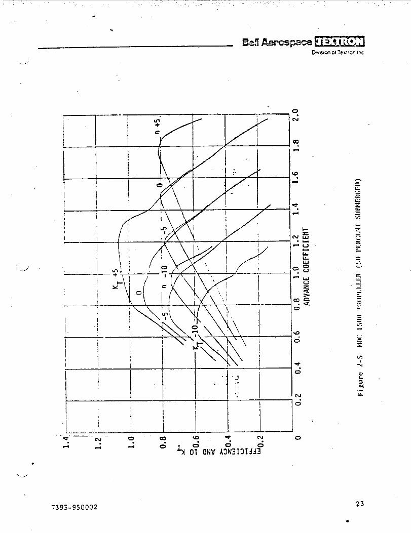
.._J
“’d’
-T ,—.
$ / I
e
1. , /.
____:._ ~ ,, ., . -p
,:
II I
&I1
i ~ ;
iI I
●
ccL:
.,=z
.--
d
25
●

w(J1●
KJ
1.2
1.0
O.tJ-
v
ILu-W
0.
.
—--- -. i---- I -
II,.,..:
1.6 . . .. MDC 1500 PROPELLERI
. 100 PERCE1/T SUBMERGED. ”VENTILATED
I I
~_A,T
-KT+50-1.4,
_—
——-—
——
—.
------
_—
1-----.—.-...—.-\//—..
k“ I
0. .2
ADVANCE COEFFICIENT
-.
--- -------
\
.
-5
F
.—
----- .~.- ---. —
!1“..,____.
\
-—. ,—.__—._..—.——
~ ~
0 ~~~
.—- -’ —
I——— - *---.--—
1----.----
1.4 1.6 1=8
I....-—.
. ... .. —
n +5—
k—-..—-—
—. —
.
0
(. (..
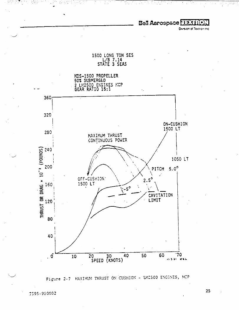
.-/
1500:,(K$ \\tiSES
STATE 3 “SEAS
~S-1500 PROPELLER50% SUBMERGED2 LKZ500 EfiGIHES FXP- -. GEAR RATIO 15:1 ..
J
36G-
320’
280
t
Io
x
II
40 ‘
I
MAXIMJtl THRUSTCON~lNUOUS POHER
I
ON-CUSHION1500 LT
//
/ i
OFF-CUSHION’ \1500 LT \
,
,050
0°
.d- 10 20 40 50 60 -70SPEED &iOTS) t!.s.$}aqk
}I
LT
“JFigure 2.7 !.!AXIWJI 11-.?.uST ON ‘CUSH1ON- !J125.00 ENGi\ES,
2s
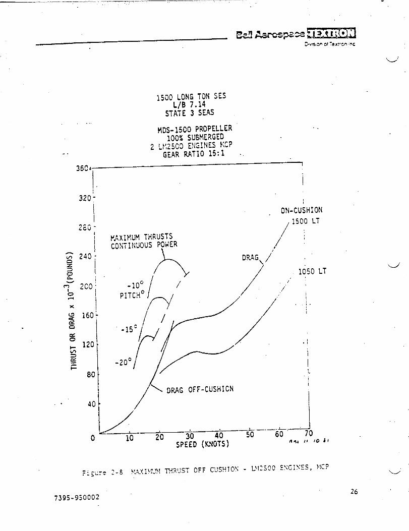
.—— ——– —–—–,..
.
1500 LONG TON SESL/B 7.14
STATE 3 S~..
14DS-1500 PROPELLERIOOZ SUBMERGED
-.2 LY,25G0 ENGINES !1:?
GEAR RATIO 15:1 ..
.
n
320;
Ii
,.I
160
120
80
40
0
PAxIMUM THRUSTSCO?;T1?{UOUSPOWER
,&
. ON-CUSH1ON
, 1500 LT
/’/
DRAG, /“
/
C)FF-CUSHICN
-: -,..,. q 8 \tUIW?lTHRUSTOFF CUSU!OS -r.~-.e --
1050 11
,
I.:.
I
.!
i
t1.
,
I
i
-J70
‘J
“u”
7395-950002
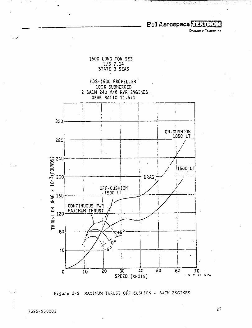
.
1500 LONGL/B
STATE
I’13S-1500
TON SES7.143 SEAS
PROPELLER “100% SUBMERGED
2 SACM 240 V/6 RVR ENGINES .GEAR RATIO 11.5:1
r
t~“ ] ! ~ ! ~
.1 !.( I #
32C” ‘ ‘ ~i:
l’!! !;i -
‘-/
240—–---— I L I
l,. ! /{ ;
~
200 I
Ii OFF-CUSHi ON
1 j1500 L?;/’.
DPAGT+ ‘ .“
I
-1
x I
g 160 “——
=C2
a
: 120!w)>ax
~ 80~
40.I
o 10’ 20 30 40–
I
I
i“I60
tf
2-9 }L4XI!4LN TERUST OFF CUSHIOX - SACM ESGISES
27
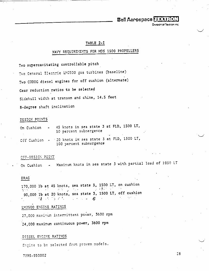
MI A.wcq3ace !!!’D.*on 01 Textron mc
TWO
Ti o
Two
TABLE 2-I
NAi’Y REQJIRZ~!EkTS FOR MDS 1S00 PROPELLERS
s~~ercavitating controllable,pitch
~~a,.a=l~~~~ectyic L!.!~jOO$a5 t’~rbines (baseline)
CODOGdiesel engines for off cushion (alternate)
ratios to be selected
at transom and chine, 14.S feet
inclination
45 knots in sea state 3 at FLD, 1S00 LT,SO percent submergence .’
20 knots in’sea state 3 a; FLD, 1S00 LT,100 percent submergence
. . .
. ~ ~usl?ioil - }!axinm knots in sea state 3 with partial lead of 1050 LT
DR4G
170,000 lb at 45 knots, sea state 3S ~~~~ LTs on cushion. . .. . ., .“ ;.’,.(. ,. ,’ -, - -
90,000 lb at 20 knat;, sea state 3, 1S00 LT, off cushion-6-”
27,000 lT,2Xi-K irfiem.ittent pc~er, 3600 rprri
‘24,CO0naxinun continuous power, 3600 rpm
‘w’
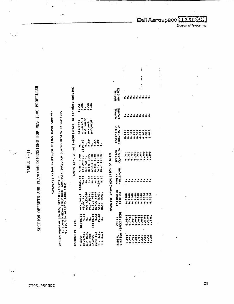
. . .
*
J’
.
eo 00*O w-● ***.
4*e*0
0 @o0 $ ao
● .*.****Oaocoomo
w
00 oeooo00 Cc. eo. ..*.*.*Oae-oe; m0-0 9
* Qa
I ti
i I
.. **.**. .0000.0000
,
.*, **.***000000000
-00000000OeooeooeoO.w**a-s*o... ...0. ●
OOOm OoOo -
0000000-0OoeooecoeFjmn-l-, nnnn.* *.***.*
000000000
.* .**...*000000000
u:
[email protected]. ..0.....
-Oaeeoooo
‘d
9
7jQj.9jooo2
●
29
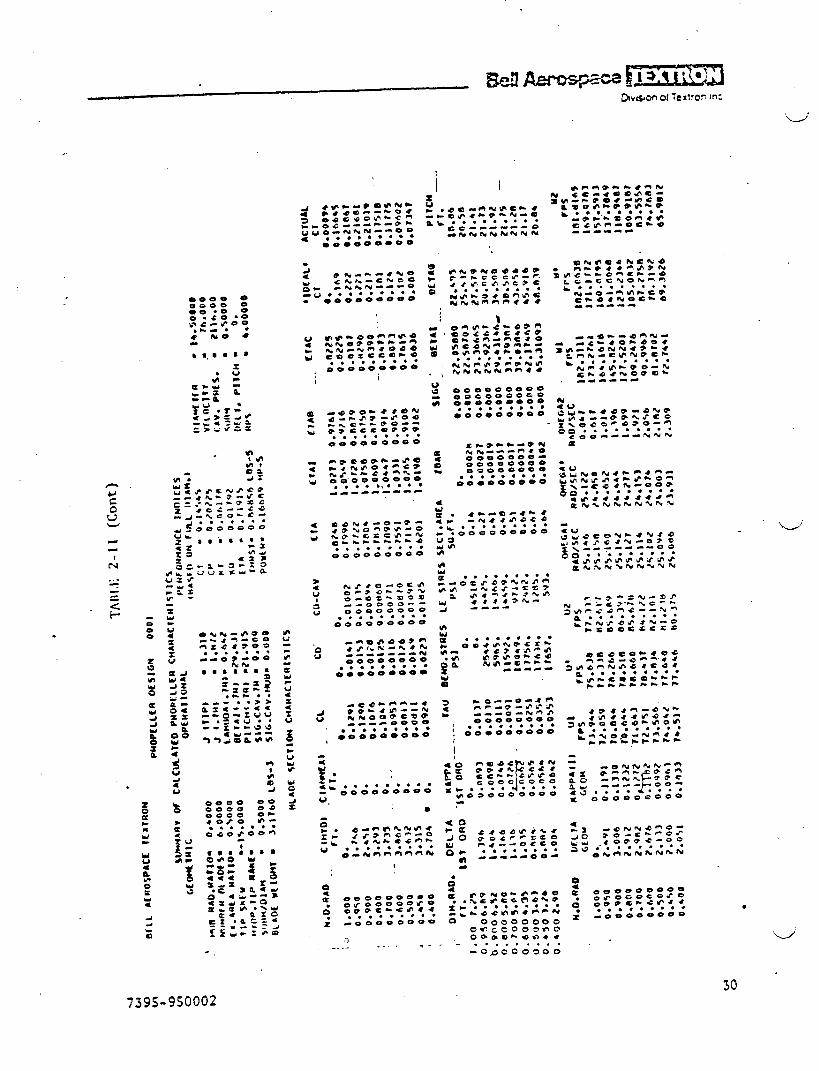
,
t
,
.
n
-wcs .
m
*.
-l-lma4as-,,,bl% -*8*------- N-0000000
● *..*.***~.000oooo
r,
t
n.~: ‘*b....**** ●
*-0000000v
●
.00000000=000● OrO
.0
;iee
,
●
o– 00000000C.eccooclfieOmbuf-gr).e
. . . . . . . . .
-O QOO 0500
3----- . ..- -
30739.S-9S0002
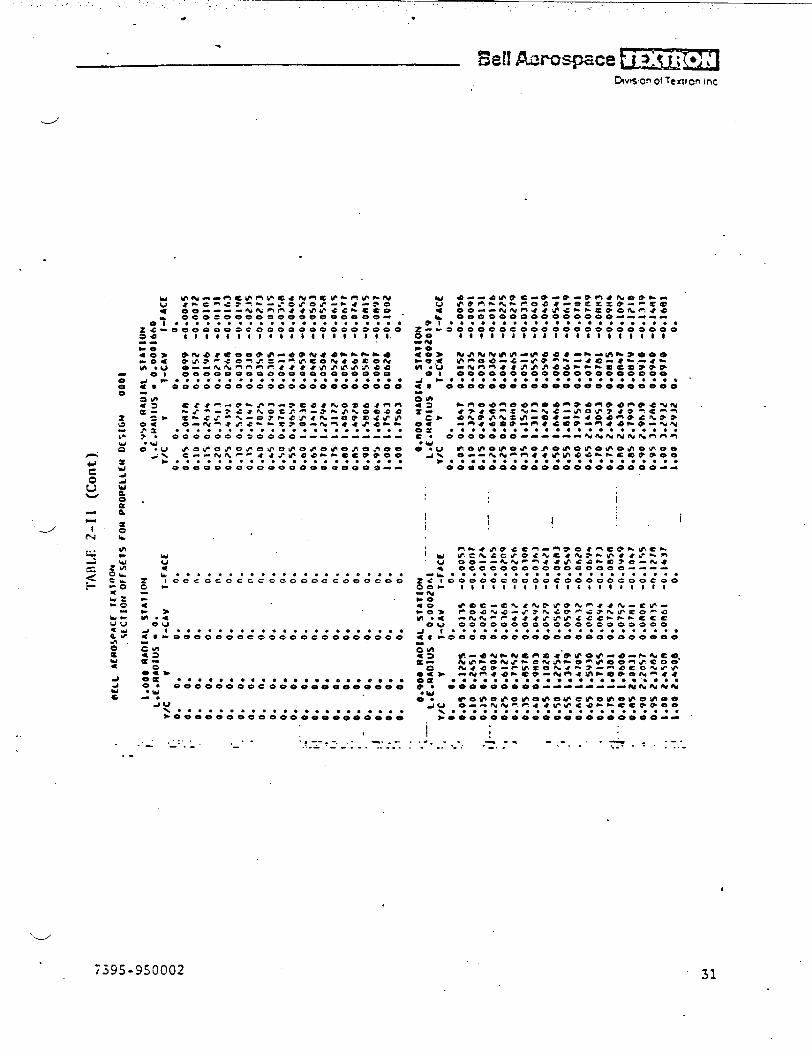
.,, . . . ,. ... . .& ●
“
!%!!Amos-pace ~j’’’j””bwon d Texvon inc
J
.
n
1
Ii 1 i,.
--’
U:
L*****..*. . * ******.** ● *x lec<eccccce Coooccoooeo 00-
.
:m.:Ou
a *.*...**** . *..*.***. ● *.● m- OOOOOee. e 00*eeooe~*e *~-
CWI
s:o?-oa ● ***.***. ● ****.*.* e.. .0. 00000000=000 0000000000
2 ‘.au
% ..*...*.. . . . . . . . . . . . . .Wooooqoweane ~*--***~*--
.:. . . . .,?--A-* -. -. .--,.- ----’ ___ --- .-A ---:-- . .. +.2.. -..- --”: . . .. . . . . . . -..;- .- ..-.-
‘4
7395-950002 31

●
0.00td
Gtt.J
.
“1.1
./
,
i
I
iI
1
I
‘rA[\[,E2-II (Cent)
0.700 R401AL SJAJIOWL.t.ffAOIUS ● 0.0001S60
v/c v t-CAV l-fACto. 0. 0. 0.0.0$ O.tm? 0.01%? -0.00*4O*IO 0.3?J5 0.0?6* -0.007s0.15 0.5602 0.031% -0.0114O*2O 0.74?0 0.03?? -0’OIS’J0.2% O.*J)T 0.04)4 -0.07100.30 1.120% 0.0+66 -tJ.o/hr0.35 I.lorz O.O+J$ -0.0 )290.40 1.4940 O.O\At/ -0.0 1~110.+s i*clnlJl O.OmZb -0.06710.%0 t.tt67s 0.0b68 -0.0ss 10.%5 2.056/ 0.0708 -0*0*1*0.60 2.?*IO O.ovbl -AJ.07/ft
O.*% Z.b?l? 0.0785 -o.oH7h0.?0 Z.bl*5 O.OR?? -0.OVJI0.7s 2.0012 o.oAt57 -o.lo~~0.00 2.9880 o.ota~? -0.1166O.B% 3.ir*7 0.092s -0.13000.90 3.3615 0.09s6 -o.1*4~0.95 3.5*t12 0.0990 -0.iblb
).OO 307330 0.1O22 -0.lfJJfI1.00 3.~150 0. n.
0.500 RAOIAL SIATIONL.CORAOIUS ● 0.001140@J
v/c v 7-CAV l-fACt0. 0. 0. n.
0:05 OilslbO.io 0.163/0.1% 0.54+6
.’-” O.ZO 0.7265O.?t 0.90610.30 1.on9r0.15 1.27110.40 i.45?90.45 1.61+s
0.s0 t.nlfll‘, 0.s5 1.997?
O.*O 2.]1’?+
Ohs ?.lhlo0.?0 i?.5JJi’tl0.7s 2.7242O.no 2.*OMo.m%”3.oft7*0.90 3.2t1900.9% 3.A507).00 3*63’f)
I*OO 3.6323
0;0?360.0M9O.0**00.0%J9Ooowva0.0654
0.0?14o.07ro
0.06?3
0.0R7*O.ov?l
0.0970
0.101sO.lo>n
0.1100
0.1161
O.IIHI
0.1??0
0.1256
0.1295 .
0.
-0.0179-0.0?63-0.031FI-0.0411-0.04H4-0.0ss’4-0.06 1s-o.or\)-0.07WJ-o.on7n
-0.0965
-0. ln%h
-0.11%1-0.1?%0-0.1 )<>-0.1666-o. 1%95-ft.t714
-(t. 1859-n.zobb
o.
0.600 FJAOIAL StAIItJM
L.C.AVAI)IUS . 0.000/325?/c v 1-CAV 7-FACE
o. 0. 0. 0.0.05 o.)QI] 0.0t6b -0.0061
0.10 0.J662 ,0.0/’86 -nolo)
O.is 0.5793 o.OJ/tJ -0.0!4%0./0 0.??)+ 0.01’12 -0.019ZO.ts o.fJti55 O.o+!to -0.07460.30 1.15Rtl O,O\OJ -0.0 )050.3%” 1:J517 0.0%%3 -0.0.1660.60 1*%446 O.ohoo -0.U*]?0.6s b.?lrlt o.otb4* -U.o%tt
0.50 1.9309 O.ohtb? -0.0”)900.+s 2.1<40 0.01?0 -0.0675O.tlo 2.JtIl O.O~b? -0.0 rh%
0.t15 2.%102 0.0ft05 -0.0nb20.)0 2.7033 o.on4t -0.0965
0.1s 2.fiv6* O.on?o -O.1OTAO.no .).ltmw 0.0913 -0.tl$s
.o.~s 3./tJz6 0.094T -0.! 3250.90 >.41s7 o.owo -o. 14tD90.95 3.6enn 0.1013 -0.1632I.no 3.n619 0.1044 -0.1121
1.00 3.@61V O. O*
0.4S0 AAAOIAL S1AI1ON
L.E.nAfJIUS = 0.0020?42v/c 1 7-CAV l-fACt
o. 0. 0. 0.0.0S 0,1650 0.02?6 -0.O?SI0.10 0.331s 0.0405 -0.03%00.1s 0.49?3 O.o%oa -0.06*40.20 0.6630 0.0s96 -000s310.25 0.IWM3 0.06?6 -0.06160.30 0.99*S 0.0?66 -0.0?000.1s 1.1603 o.ofJ13 -O*O?M0.40 t.3/bO 0.0s15 -o .ofth90.65 I.*UIAI 0.0~J4 -0.U9SJ0.S0 8.b57b 0.0991 -0.10440.=9s t.tM33 0.10*5 -.0.1134O*AO 1.Qlt91 0.1096 -o* t?za0.6% 2.1540 0.l14b -0.! I?*0.?0 2.J70b 0.lt94 -o*l*z*0.?s z.wm~ o.tzto -o. I%znO.RO 2.6521 o.tzn6 -0.lhln0.s% 2001?IS o.iJ29 -0.1?540.90 20WJb 0.iJ12 -O011J?9
0.9s 3.1493 0.1414 -0.?olm, I.otl 3.31SL 0.14S* -o.i?191
1.00 J.J15i O. o*
*
(. ( (

-.
c8A
000
.,
..
...----
-?----
...i
c--.--’—
-----.
..
.-...-
7395-950002
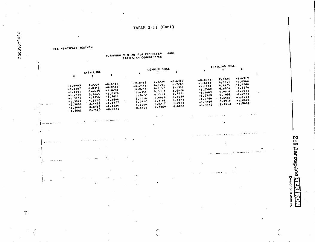
—.
...-.z<‘+
000
1
m
...—.
t
II
Ii,.\
II
,,I
“’-.-”
..
.
,
.
1.,
!
1I
i
1I
I!
II,
..—.
I__
..-A
-.-..
.-—
-..
..
‘4’

n“wc8
xo
O“---e*Qe
-A
#rsrscexc-.e
----00000●
.*******0
00
0O
eD
oO
4e
-41
-*0s
-%’%JNOO>
2=
*&
----oaoo
●*....**
●
OO
OO
OO
oO
-
m*8
n4
s>r8
Qm
-im-o>
.rc?----.-ccc
0●
....*.*
●
=Oacooooo
-e>e
’w%
--?P
--,--aaC*
---.-->
00
...*....
.oeeoooooo
..
..
..s0
’:0000000
O-w
*-e
%&
aa4a-n-0e
--------
--●
**..*.**000000000
00
00
00
00
0m
oo
eo
oe
oo
Ooeceeooo
.***...**
---------
.-.
.
.********
00
00
00
00
0
*-Q
-*.%--O
*e>=-l-4
*-0
00
00
00
00
●********
Ooooeoeae
@--*
’%**8w
eoo%s=
-da----000000.
..******oooeooooo
*=7-co>>-
0002==&
c*
--..e
aa
oo
o.*
***...*000000000
O--n
o.%ooo
---*es*-a
--ao
oo
ae
o,
.0...0
..●
00
00
00
00
0
@&
a-a
*--m---ees--e---.0
00
00
0.*
**.**.*-0
00
00
0--
f-a*v
a-m
**-.--@
ee
.#-*
---00
00
00
.*..*.***
i000000000
IV
coeooee
o-o
\a0
80
00
00
1A
0●
aO
e*e
-e*84
N********
●
=-0
00
00
00
0I
.—.
..=.
;,..
4
7395-9S0002
3s
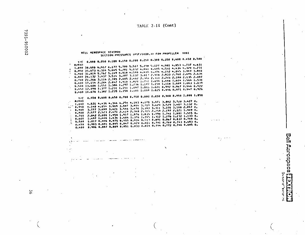
●✎
✎✎
☛☛
☛☛
✎O
eo
oo
oo
oe
00e
-ucs
’4’
!i!iI
.:.
....-.zs
000:‘4a.
..
I.
1,
!II
U=e
oo
eo
oo
oe
\*eir
OO
OO
O@
0ma
Ov.YG
*Gk-,4**
%*.=****
=-00000000
.
t
36
‘739
S-9
50002
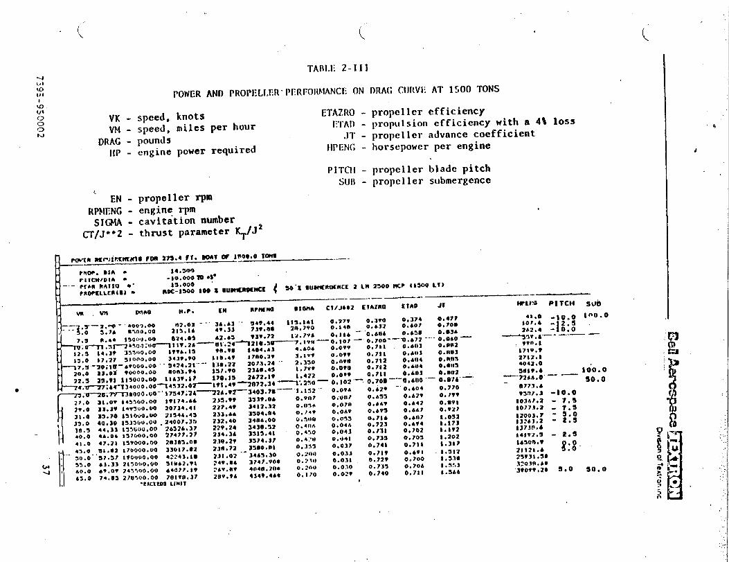
“.-J
e00
0.0c.
mmo
ee.1o..●
.
“d1
11
1II
.A...-~<+
un
-w
J-
ItIl1
11
1
‘.-./
37
7395
-9S
0002
●

,
4bluu-!I
TAl\l,E 2- lV
POWER AND PROPEI,l,I;R PERFORktANCE ON DRAG CURVE AT 10S0 TONS404/1o00w
3AO0. ,24000.
PMIP. DIA - 14.500PIlcM/oln - -io.000m +7. s’othn nAllo - 15.000 ‘@f107’ELLt RtS) - IOX-lSOO SO X ●UNWnOIMCC 2 Lt4 2S00 MC? ,
blw
-— -.. .UKw Oaw $4.?. CM R?44L no 81014A CIiJ842 EIAIRO Elmo Jr
J?*S 2S**1 ●?s00.00 9103.11 IS7,2A 2400. s7 ~,422 0,915 o.bt2 0.464
YST6-7413VmOOO.00 ‘IO~o@. Z6--”-l?T. &~-;; ;~:;~ Its? O.ohb o.?8& -O, m?
27. !l 31,67 VV300.00 12$39T24-30xr-34?>n64>oo; od—
1s6, ?0 0. VT12 0.037 o,7’Jh 0.4?113 Ae?. zmo7; ?*-ltv.8n —-0. HOO—’ O,o!)l --’0. 733” ---0.703
32.0 3A. B!4 Io?ono. oo i4f4J5*27 202.7!4 3042.V3 O,)** o.04h 0.730 0.709=3;.~—Y4.00 10?-, OO.OO 1?,?91.41 ‘. ?OA. (f4 “ ;;;;:;; O.hht e,041 0.741 0,712
40,30 I06UU0.00 b3v24.4w . LYV.4? O,:,tia O.o.!ll 0.743 0,71s3*. O 44.91 Iolooo. oo tA7’4%,4v IVII.1* zv/?. +3 o.4t J 0.0.10 0. Idb O.?m+i. o 47.21 10:300.00 17?01.44 20+. 70 JoIt.&* 0,420 0.02? o,7t3 O. ?42
43,3 ●u.v4 Iollooo. oo l*t77. b2 I*?.04 2?%> .34 0.3V13 o.02& 0.7*4 0.7334s,0 S1 .92 111300.00 21140 .02_205. ~S . . 39~!?*21 0.1?3 ,.- 0.624 0,??2 0,?42S0.0 3?.5? 1300 U0.00 2bnf.>.37 212. .I4 31 U3.17 0. .,/111 0.0:!. } 0.7?4 0,/43
33.0 63.33 I:looo. oo 54011!,. r> 211. VI J4711.?O 0. :’.IU 0.0:2 O,)?v 0./6(1&o. o &?. ov 17rooo. oo 43739.s9 238.22 337.3.24 0.200 0.0?1 0.777 0.746
64.0 74.00 210300.00 -5?oir.34 241.2? _avtv*ov* 0.IA5 o.02t o.7rv O. 1.49—.. — .—— - ..—
●EXCEEDS LIMITS
(’.
0.03s0.673O.*75
-.. t.ooa “--
I.1021.$I!41,22A
Wwto rltclt sum
4s31.4
!3304.i&o&**4
- 4e41. v”?41?.4?4.4a. v?962.0e.til:. vMvso. ?T30m. n
to3?4.4SY432.8iJ04?. v2104T.028s08.76
-:0.0 50.-10.0 50.
7.s 30.-7.3 50.-3.0 w.-3.0 30.-2,5 50.
0.0 so.0.0 :1).
2.s 50,2.s 50.3.0 so.S$o :0.?.3 30.
7.s 30.
(
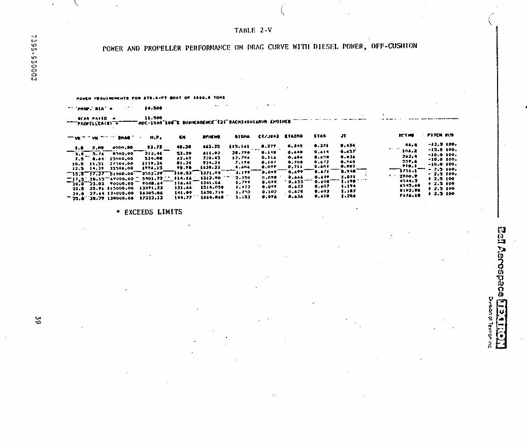
<J(.8Q4JI
I
GL/l
o00t.)
\<
TAI)I.E 2-V
POWER AND PRO1’ELLER PERFORhtANCE ON PRAG CIJRVE WI”UI ~lf:sl:l,POl~ER, ~FF-CuSlllfjN
-. ....- ..—...-.- —-- -------- .--. —. .—-—
CIAO Jl K-tn, - PIICH W3
0.331 ●,4JA 4A., -12.3 100.
1,s ● .44 JY~oO.00:::: tl*!Jl 24300,00
14.3? 33500.00
Ts.~nlmo;oo—bvooo. vo
Yo:x::z Toooo ●OO22. s 23.*1 I150Q0.002*. O ‘27.44 IY4000.00
b ?a. o”’”Jo*m !J*-*OQ
S24. S0 42*A5 720.43111*.2A ● 1.24 934.24:wA. Is To.*@ _li311*22
—mo2:?*- 110,53 127t.n9-- Sqot.m “- 114.14 _tJ12. ?o ‘- voa9. b4 —-l lb.&t 134* .04
lJo?t*23 131. A4 l!t14*0391AM3.6A t41. oo ib30.71917332*ia i44*7? “ “ 8444*R4$
● EXCEEDS LIMITS
t2.7?b?.STU4.404
-J, !?v“2.390
1.?9?
#.422
i .270
1*A52
-.0.A14 o.di?’
O.I IA o.4eb o.4sm 0.-140.107 0.700 o.4t2 0.9400,0?9 o.71a 0.401 o*M12
—0,07V—0;4W —0.4?1 —“o. v4a -
C.a?a b.bhb 0.4JV l*07a :O.o?a ‘0.433—0.400—::;::-’””0.0?? 0.A32 0.40?0,102 0.A28 0.403 1.1020,074 o.43b 0.480 1.204
. .“’ *o&ea
242,4339.4tl,.1
---B73t*i-
“ “ 2*00**4344. s*3*!I. U● lwJ. W6*74.1*
-1s,0-10.0-10.0-io. o- 7.3- 2.3b 2.sb 2.3
4 2.!24 2.s
too.
100.100*
too.100.too.100100:00
100
wu)
4
.,,

,.,“.”,’, .. ’..-, .: ..,’ ., ..’.. ., ,”... ,..
.J’
‘w’
. . .
5ECTIOX 3
COSCLWIOSS
..
40739S-950002

._/
h efficient 14.S-foot diameter pzopellcr has been dcsiwd for the!SS 1500-ton ship.
Altcrnztives of one gas turbinz per,pr~ellet, or cne gas turbzne and one
.
die~e~ ~ach, 5zx*esignificant gdvant~ges, dependent upon the use of the
A denonstratcr SES with only gas tusbines }:ould gre2tly Siqlify
vessel.the propulsion machinery. Hoxever, the range at off-cushion speeds would
be r.uchgreater with diesel power and COOOG reduction gears.
3.1 Reccr.ne~2ations
.
Contin~~ethe p=opeller design effort to define the propeller hub an?inte~$aces between the propeller and the hull. The d:s~w must satzsfybcth perforzzzce and structural considerations.
}!akethe propcsed inprovenents in the SCRP co=puter program, so that the
experience ~a.ir,edin the present project will be readily available for the
design of ne~ strper=>’itatingpropellers.
_.’.-
.-
.
4173CII-9S()()02
APPEN)lX A
. PRIOR REPORTS
“-J
42
7j9S-950002

. . . . ,. ... “., ... ,:.....’,.......’. . .. . . . . . ‘“.
.J
APPENDIX I
SULZER-ESCHER WYSS REPORT
.-/’ .
,’: . .. . .
. —_— .--- —-- -—.—— —-- - -— ---— -—— —— —--- ---- --- --- ----.--.—- - —---- ---- -. - -- .-..---. .— -—. ,---— — ———— —---— --..—- .--—-— .— ---- . . . ....-.-— .—--- __, -. .._. __ .
- -— ——— ——--—.-— -- ....— . ———.-— —---— .- —- -. --—- -. .-.. .— ---- ------- . ..-- —--— —-— —-- —- ---— —..—— —- —-— —- —-— —.--—.. ----- ..--—. -._.. ______ . .--— -—-. — —.—— .-— --- ----- .-. —--— --.-. . .. .... . . . . . . --
.-0”
—.—
.— - ——-—- -- —- -— —-— --—-
—— —-
. .
‘J
SURFACE EFFECT SHIP
(SES) 1500
Enclosures to Report No.:
170100/0010-02
PROPELLER DESIGN
.-/
.:
——-— -—-— --- .-—— —-. . -. -— ——-- —--— .—--- —-— —.— —— —-— ----.—-— ..— ——.- -. .- -—— --- —
.—.—-. — -- —-. —--- ——-——— —— -- .— --- -
..- —-—.— —- —-- -..-.—
.— _—. —----- .- ——~ —---——--— .-—-.—— ~——— ————— ———.-——---—- —— —-.—
~
A— —. —.-. — .-—
.-.—-. . .— —.————- —— —— —— —
:’.., j-!w)!w) t-) }.[!- ~:.lf.dc (,? 2:I(KI r.+0.:dfG I.(JICI-’.,:; 1(-:01.- +.ll() A ; ?’:: “--’.-.. . -. -— —--—---- ----- —-----... . ..-.-.--—.—----------------- ---- -----------. ........_.. . .. .----
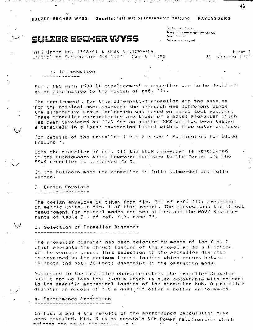
,. . . ....,, ,, ,: .... . ... .... .. . ,., ., . . . . . ,,, ,.. . . ..’ ”’””’ ““. .. . .. . ...”.”’. ...~.: “., .’ .’.
* 46
SULZER-ESCH; R WYSS Gesellschaft mit beschrankter Ha ftung RAVE FJSBURG
J. , I 1’ I +:. I’c)cj IJ(l “1,,iC)l”l!.
. . . . . . . . . . . . ---------- . .
.
----- .. . .. . ..--------- -----
u ~, se~ectiorl of F’r~F+211.c+r Ili ameter----- ----- -------- ----- ..------ ----- -----.,
SULZER-ESCHER WYSS Gesellschaft mit beschrankter Ha ftung RAVE NSBURG
:,.,..1.,, , i P, ,!.
we,,,.,,,, . ,4,,,..,,.*$>*.,.,*,-.,.,,,!,.,,.. ,,.,
cWL2X3?! ESCHER LJ5?JW5~: 1....!.,.s8 ~,$,’$’1..
.
“w’
.
●
✍✎
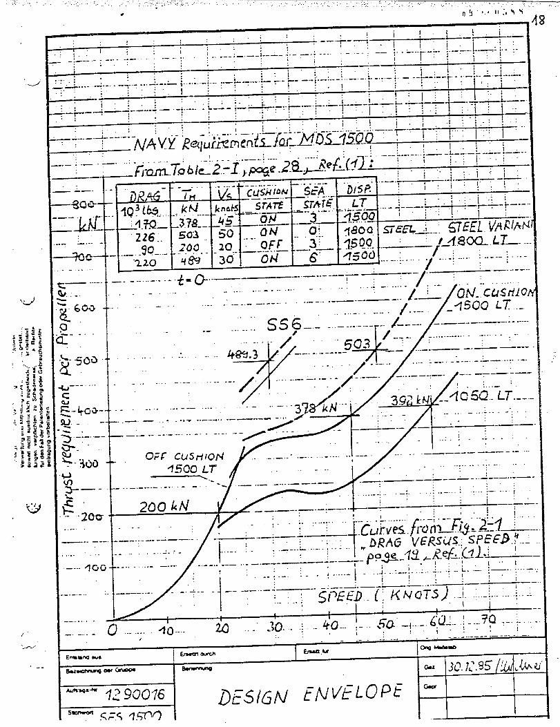
.-/
“d
{ 1 ! I ____:’ -—+-l . ~
, I !.: ~ !. !i. . . . . . L+... ---: ---- ‘ - -“ : ‘—
*--.;— .— -
;. . L...
. . . . . ---. : ..; -.,--: -—- -: ----: I I ?
,
r-:- ~.---.-.l--’;...;.’
.., -—-“” ;.;
~: ~’ ii i. .. . . .. . ,“. --- ‘L-- _... ~.- -: ----- . . . . . -------- !---- y-----
. . . +.-L *..-.-..-:....:._;_”-.--”:-- .: , :, [.- ++.+:..
ii~. 1: .... .-~.-. . ------ ~ il-,
:. 1.:”. :“;“, :., :. . -- ,._- :
:.:.
i’:, ; --- : ~ : i, ; &_._–-.&Lk-k -—v--. . .
:: L,-+----- - — -: .”--- - ,------ -- .; :””: :,
:; . . ,.”—— ,
I i.: A--+-&--:.: i; .!. ;. :,.; ~.:~.
i _L-_ .1. ... ...---- .-!.—---&--i ~ ~ I .:.: ~;.~ ~kYY- ~ai~iS&FrifCJNFN.0L75Q-Q ; ~ ‘ ~
1.__ .-.-.+. - -----:: ;“:. ;’~
,, :“: -- .-L --—y——---.,. . ----;------.—--: ---- -~—. ...-.’
_fi:%.7ub122:-l;&e-J-~L$=~~f2 : ~ ; ..-~” ;;’ ;j :I---- !-( I ~ ;~--y
LT,---~— ““--+----- “.:+-r : t—.- —--
--—”— “?.5Wfisou. siEE& 5WEL. VA~h~mm ...._—— ‘~f_?.8W.LT—-45(X) ... ...... .. ~------
-220,j ; / ....\..... y ~...
-------- .+= Q.-—-—----- --------,.. .— -----
,--
——-,,.
_-——. .
—gf-J&
-M--- -.— ..-
:---- -
-+f3e–-..
,— ...-..}. . . ..
-- -
__ -.. .d
g.- -
------
—--- —-
....”. .-
---- 4G{
-----
. . ......-
_. -----
—.
.
.-
-.
.-. ..
-.. .
.. . . ----
-.. . .- .- ..-.
. ..- ------
—. —., -i -. -.. .
—--- .- ---- --- -----
,.-.
.-
-.
----- ---- / ~ -- ~~. ?- ““”“’”. . . . . . . . . . . . . . . . ““,
/
L-- QN-, CUSMC------ --—---— ---------- -------
1----’ _q50(2 i~ .-... ...- -------
...’...:Ss 6----- ...-.-_r. /--- /.__---.:-..
OFF cU5tlIOH ~. _._. ..... ........ .-!..__./... .. ------------- .-.-.‘lf$OOL~
.. .. . . . -, --:------:.”-. . .----- ,____ ____ -. .=--— ..-—
-_. .—------ ---- --- :’:.. :..- ... . .
:. .-..-:..-.— .-—+.-—-. --—--— —.-. DRAG VERSUS.; WfB~---
--.. .. . ----------.. --—..- —-—-- _- ——-u-- —- p%i=~z +Rez.c+l .:
------- -. ~-....- i ..{.. ,_j.. +.. j.. .; -.~ .:. +-.. ‘..:.-.,!_
0 -- +o --- ti ..” i). ..:.. - (0... ~-.. @ +’+.- .~-.:-~p :- ~-”:------------ .—--.-—-
hJ -*
1
I—
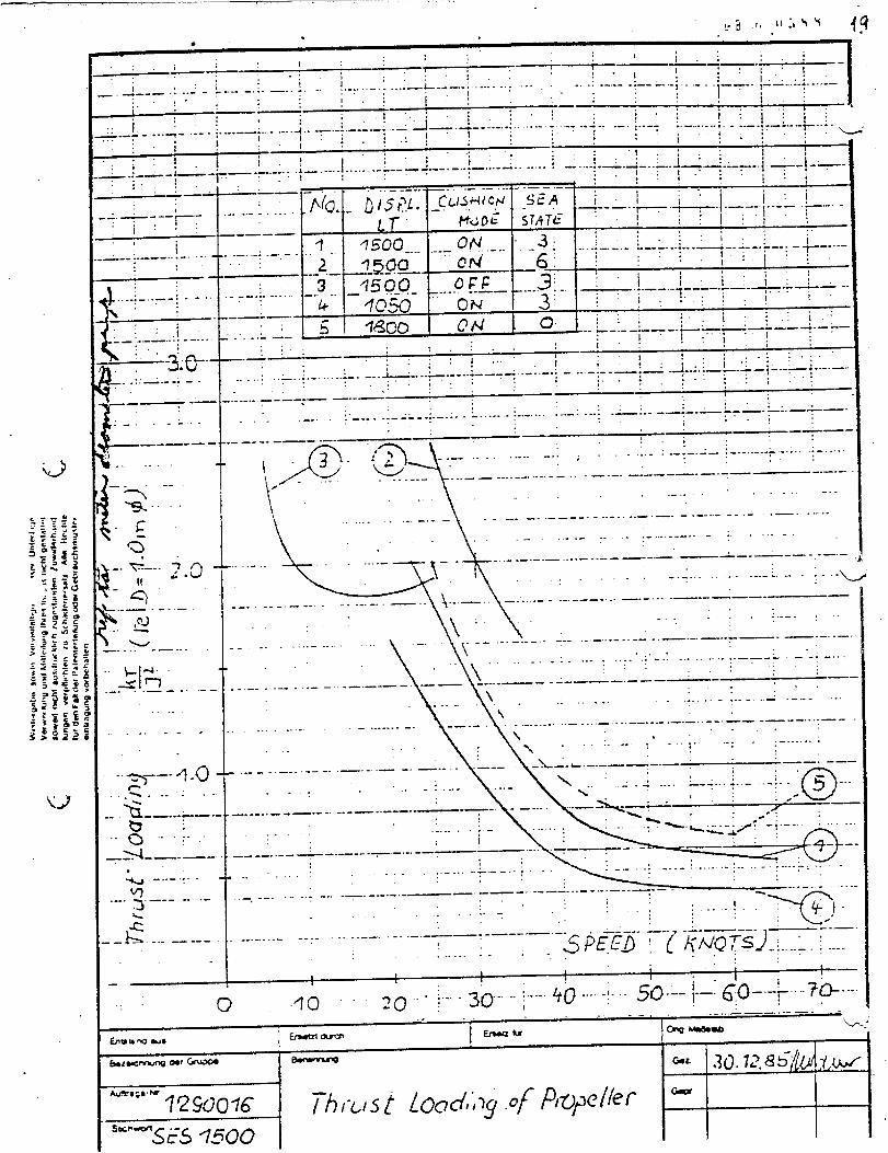
_- —- .
. .●
,’ , I—— I -~
,.1 .- -I 4
-. I.: I i.: !. I
, ; _,; . _~. :.. .,Ii . . .._-- L.-—.-. . . . . . . . . . --.’ . . . ----- -: —-—.- ,. ..-..’ ——
-. 4--— .. --- - r---. . . . . . . . ..-
:.! . i’. i i ! j _~ I,. .- -I
~ ; -. [__..:+_.:_
~.~.i ~:’++-- ..-..:.. --- ; -, --{-- ‘ ._.J - ...:----- .–--:..- .-.. +.+.-.--; -- .-. ;----- :.-....-..;.- __!+..-i..i. >’
.i 1 “:..’.;
i’t”::’
!, - c._.. .l_ . . . . . . . . . . ..-.--> ..--.-. -!-.. .--... -----
,
;,1;i -... .-~--_ .;_..;_ ;_-L___~-.~._-~ --- \
_ -: ----:~.
-- —-
I__. L__---------.L--:-.--i--~l’”~,.~+:+ .-:..; ;::3q-..-—-..-1.
Is. . . . . -— .-.
. . . . -
.-
-“>––- ~ “o-------.--&_.-._––..8 .......
=l_____—-..-Q. -... ... .
..-.y -----
._i5..-----
.’1 ,:’. i“!,-
i’ i:!+---+ [ ~------ ..-———
7
-.,----”j---- --”-iq5Qo--
---:$: “-“- “._3; - .;------ :-----.;...=+- :----–; -y-----.—,.+.- -- ..-.2 -9~ocl 6: !— ---.——- ---—3 Llrg
j: ! i ; JJ___:. q5g-o- ..... ,-—– ------.;..... ---- — -.. .—----------- ,.1+ dos k ON
-J-:’!: !”; ::!i’
.—-—.5 %00 ON u“ i i i ! ‘ ~ +_&;-r -- y-.-—..—— ----~
l“..!,;;- .L ----::. i::.. . ,
_._~i 1::: :!.
‘ .+:.: ~ “- “ i_.+_’_.. .._.. _.. L_ .._. --...--__ ..-..--: - ...-. --—:— .— --- —,.. . .. . ,. ._. .; .-. . ::;,;“::’ . . . :.. ” ‘;
,~”:----- —---.— —.-—
,. ,. :.;. ._ :.- -._: ----- =-—.—- . —-—
..-_ L-.;---- - - -. . . ..- . . .. . .. -------------- -.. :— -- -. ‘. ..;
-- —— -- —-— .. -- .- -—- -—-— !,;
R
32.- @
‘.:x ~ ~ “ ~~
:.-.-.:--._....-.+.-—..\-
-.—.........-...-,----, .......
\
.-_._.—-——-—-—--—— --—-—.-----...——--------—--/-”- -----.-. .. .
L
-.—-----------------------------—-.——-------.. .—...-.-,..- .-.,-----..-.. ....----....
___ _---—-,-—.-....—-~—- -------._....-..-——--—...-..
.-. . ----wt-~/~------’--’-’---~’i--::--. . . \ ~~ y -. . ; ,..-. . . .
““’-\/ .-:~:.-,—-——-... .-............... :~-.------“-”–--””-- -’: .,. . ;._:_-_..-“-; --
\“” ““-” ‘“--:””’-”;’_-’ : ‘–-.. — _-..-—— ---——-—.-——-.--. .—---— .- —.——-\ ., ,. . .. . ,:.. ..- :_- ._. .:.--’ ...;. .-. .
\ ,-, -...-.. ... ..... ..... . .... .-.—----.——-—---- .:—-........ ------------ —--- \ ,.,l.- ~~ \: Y\ “ “’:””-- ‘--””!- “-: - ~--------d
-11--. -.-—--.— : : ; -—- ––--.—------- .—. -..— -. —.- .----i . ._ -; .. . . L+...:..- .-:. .
.“ .- -: . ..-. . .
_. ----- ------- -. -—.. -----
‘-. . . . . . . . . .:“” I1
-------- --. —-- --------
;---- .: ----. . . . . . ----- -’ ----- -.-~. .
..” . .
------- -——- . . . ..- . . . -- ----- .-— —’—— -“
.- —- . . .._, -- .
-. . . . . .
:“.:.. ‘Y’1..:.
“.. - +) ~,“ . . . :-- ”-:,,
_— -- —--— .-. .------- ---- :--- -- .-— ---. — .-
- s ?<5~-lZz-7ia-;::”_.....-..:, , 1
—, t 1
1 I 1—— 1 ,
0 ’10 ‘ ;----”+0 ‘-” -1-“ m--- i-–: 6$+”””-%---”Qy” ;.-.. 3~..-i
I
.____— ..- —.-hg -ma b.

u’
!.<
... #
-d
.
—
--
?3.....—
.
%. !.
.:
1
—.. . . . ;..__;..l....l.___.~..._.~.:...;....!..j..:f--j/+--:----.;----._...-.-.:-.....-.i._.....,.’ : .: t
-.. .
i .: .:.: :,, ; i-:--i- .“-l ----,
:: :::. :: + i J,.
-.-...:. ;__;. .:-..:...: -+ .: : ~ ~ /j \ ‘;.:
—: — —---- .: . . . . .. .. . . . . . . .: .. ---- i - -. -<-—-. ..— . . ------- .. . _._:,“ . . ::
., :’ . . . i Ii:,
. . ) I.,. ..:, :.:::. . l:!~-f.;:’l---- .----: :.,
Md A i----~ ~ -’-”~--i-:: “! “ ~ ~ ---:7: : / ! -: !
, :.---- -: . -J ---_,____ -
!. .:’..
:.: :..,. :. I
-P.-.—-.,...-—-__..L......~- .-A+ --—— :“ ::’: .~....
i“. !
“-D’ ~ l: W.::”._..-. .. -—-. A. -.--* -.. L -—7- . ..- . .._. .
1:.. I ‘:. ;:!. . .;
i’.::”~!:~: !j. ill.:.-::..—.-”: —..,. j. :-.._ . . . ..—. ..—— --- ___ .. --.:._ .
U
..:
—-.
i:.
=jf :*+-+.4 ““ : , ‘
“-””-”~.1500 l~s~n; dQ50 i-~
. . . .. ... ......—--- . ... - . .. -.-— ....—-- —-—
--
.-
.-
-. .
-.
—.
. .
---
---- P_Y23::L-’-”~---~’-2 pm -~........+....,’
—-—
. .. .
. ---
----- ..
.-
3 I7500 Lr ~.:-----~-.--=---I 6--:-/’-- - k~---~ --------j--.. ..- -----.-....._.__......
/’. :
}.._:___ ‘ : ___.-. . .. . ........ .... . . ..... .. -.&_..---,.-.,-,--,-,. ;--.-:----.,,
[....-. .... . .. .. .-..,.-.... .___... ..... ______—-— .——--.——-.—.-.–. -.– —------ ..._-. ..... _____ ‘ ~“;--:“
......:..-”.
//
= . . . . . . . . . -. -.-L —---- ---- . . . . . . . . . . :_. :::; ;’:
.,.
. . . . . . . . . . . . . . . . . . . /. -.> “---;::.-“_.<___.L:_:i.::I .,
-.. —--- ____ ._
‘-”-—–-––-–-— ‘——’. ... ...‘ ; - ‘“ : ‘“-“:’”---:–-” ‘ :-------.... ..------...... .. .....-...,___.-.--,--..
:::::;..-._. :-..___rIL——
------- . . . .....,_..- .,-:::———-.-.___----- .. . .- ... :-=--:.;
. .. . . . -. ---- . . . . . . . . . . . -: .. . -;. - -.-A. .- .-: .,. .. .
—------- ------ . . . . . . . . --. .-. — .. _A __ -— ___ . . . ___ ____ -.,
. . . . . . . . . . . . . . . . . . ---- .- ----- . ..”.. -..
-—. — .— --- ._ .—-. —;.:
. . . . , -. . . . ..- ..-. . . ---
---- - .-. ___
. . . . . . . . . . . . .-. . .. -. ..-. . . . . . . . . . . . . . . . .
—-- _. _:_. _
. . Af SKIStQ
.-Cciflbe. u.4050Lr
—. —---
.._$chedL.i/t@I tdC@. .~/R /Qff&f_.efll.C~ ~ i ~ ~ ~ ! ; 1:.I. . :---- -. . . . . :-. ~-~ ;~ ‘fi--:--- .. . .. . .- ._*._ -. -.:.- ._..:..- _,. .-..:- ,--— .. ..:..-:-
!.1 ;: :::
t 1 , i1
1I
. ...--. z~. .; . ... . ......~..._j_j.. 3@-. f...,_+_+ ___j-..:&_j__ ..;._:_.
mwMJ8
-“qz g@,6
“- SFS “7500
1
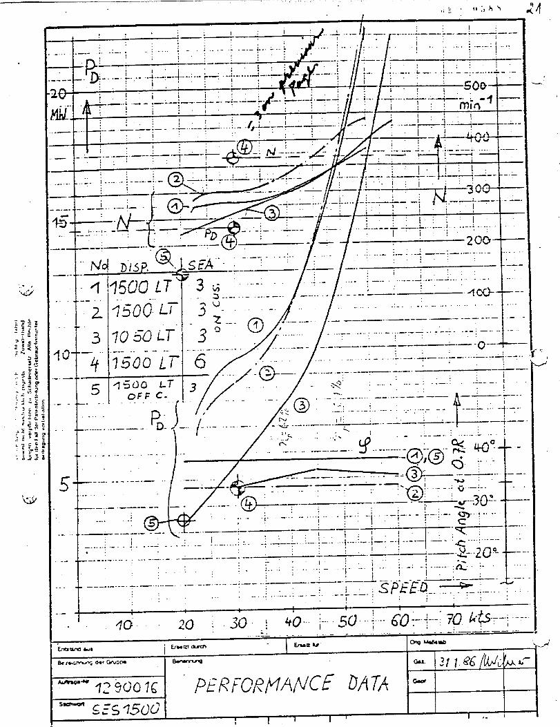
_—. ... . . ,,, ,, ,. a,
‘u
\. . .. .... .. .i. ..- .: ---- :------- .:.... -—-- .- ----
—
1’!.1
. . . . . . --- ?_.. _; —-._+.- -..
____ .—-.— -.
—
i_. &—.-.-—+.———-—-—
.. .-. .. . ..-. 1 -... . . . . ----. -:--
—.
., ;_____ _&_. L....... I - .---1----- ~~.. -------
--_..—— ..:——,.-
1;Ncj—.--’
+--
““12
3f~ –
4
t
..— —
5-. 1-- -
1.
7500L~
./l. . .............. ~j;.;..,.-. -,-,_‘..-....:, ., . , .,..
0 ._——-—..__-—- L___.—---.—.-...-----Y() ~’ ~j-’ ‘-35 ‘. .’........ , ,...,....- ~.--:----:--:----:-----
/.------
- .---- ..-----...-.... . ... _____.———-0--- -—---v5U0 LT 6 - ‘---- ~“----=L=-L-------T--–---:-+----
---/;@--” --””---T--- , ~---/.--.—.fi~dO LT 3
/
.x’ :-. — -:----!.... .----oFF C- -.
[ B
.- —-..-...—————
!
—~ +-------- ..... . . . !,. ...,In ‘
.< .- . . ..----- .--. — --- -.:\
j.=..
- .& --_-.. —---- ___ -- -—... ---- . ..-— —-
,- . . . -. -—--—— -.
,
5- –... .. ___-—____..—.——-----—.:.. . . .!.- -------...1..’‘1--’”.... .-. :, .__ —-—.. ..
$-...----. ...... .. .. . . .... ..........-.. -{.---~. ..----——,.-----..-..- ---------------:
______.--.-.—-..--—...—--—-------:.—-..— —.-.-.. .
.—-..,. .-— ---- ---- ....’ ----
1
G-aw’ta -*
04 I-—. 00?GIJorm
.-. ._:. —. -———— ---big **
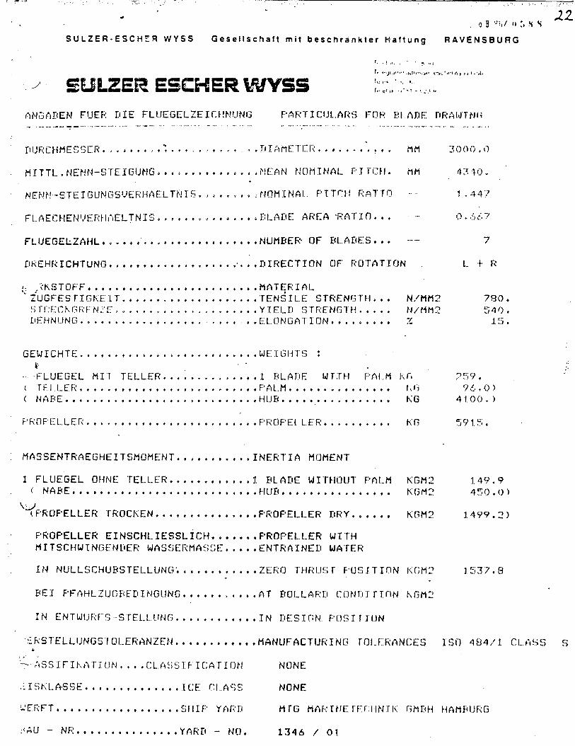
& .a n R ,.: .r r IT z . . . . . . . . . . . . . . . . . . . . . . ..
w
!-jt-
rq{—
.~
.=.
..
.*..
..
..
.
c r,n x -i T ,, . . . + . .
I !
m“:
c f- N m,.
m
G IT r
.1 I~
.. ..
. -?7
z,-
.s.
●
/-
*
~.
t=.
-i*
4*
..
..
..
..
..
..
..
..
..
..
..
..
..
..
..
..
..
..
..
-ix
P-i
>z-
lLZI.7’I
++7?
!-H
H
. . . . .
..
..
..
..
..
..
..
..
..
..
..
●✎
✎✎
✎✎
✎✌
✎☛
✎✎
-1 . ,.: r r
. . . ● ✎✎
if-
q~
,. . . - . ,
r - :- Fl
0 Fi
. . . . s
. . . . .
. . . . .. .
c-)
4D VI
. . . . . . .
. . +~ ,.- .- ~ L-
;
. .m
..
..
* .!.
0. +
●
—,.
.- = >“
z
-i
..
“..
..
E.,
+.
.<
..
~.
..
.
-q -4
..
. . ● ✎ ●
- ---:
.*.7
.
..
.3
..
.-
.*.
x
-: -. :.;
. —. ●
*.
4
-: :. . .- $
m > < m z U) m c :
-i
,.,.,

...
I..II1
-\I
./:./!
i1._._-
_
+.“’
r‘-//”
Q;,/
-..-
00inm
!●
✎
-i
Cz”
I
C3s’
I
Ll-00%
0o-1
o
\\\\
\\
\\
\\
\\
~,\
.-—
-.
—-.
-.—-
--_=__—
..-
tIIII,/’L.’
!IIII
\“\\1
\1
\
\I
\I
\
\
\
\I
\1
\\
\
-—.—
——
—-
——
.—
-——
——
.-—
-—----
-:
98-htlr-oc
83N
071U”j
h-fz?d
)\
C\
b

APPENDIX J
STRUCTURAL DRAWINGS
..v_
...~.*L.-
●

. .
.
1Houp4spfkd
I . . .m
-— .—.
Abhlhtng VWwJlwump
SECTION
I
Whld WA-L)WIWAL I ,
1=l—
.—- WOmhk- 1—. l—. —
. ..’.
:.’
,.
..‘..
.
,.
,,
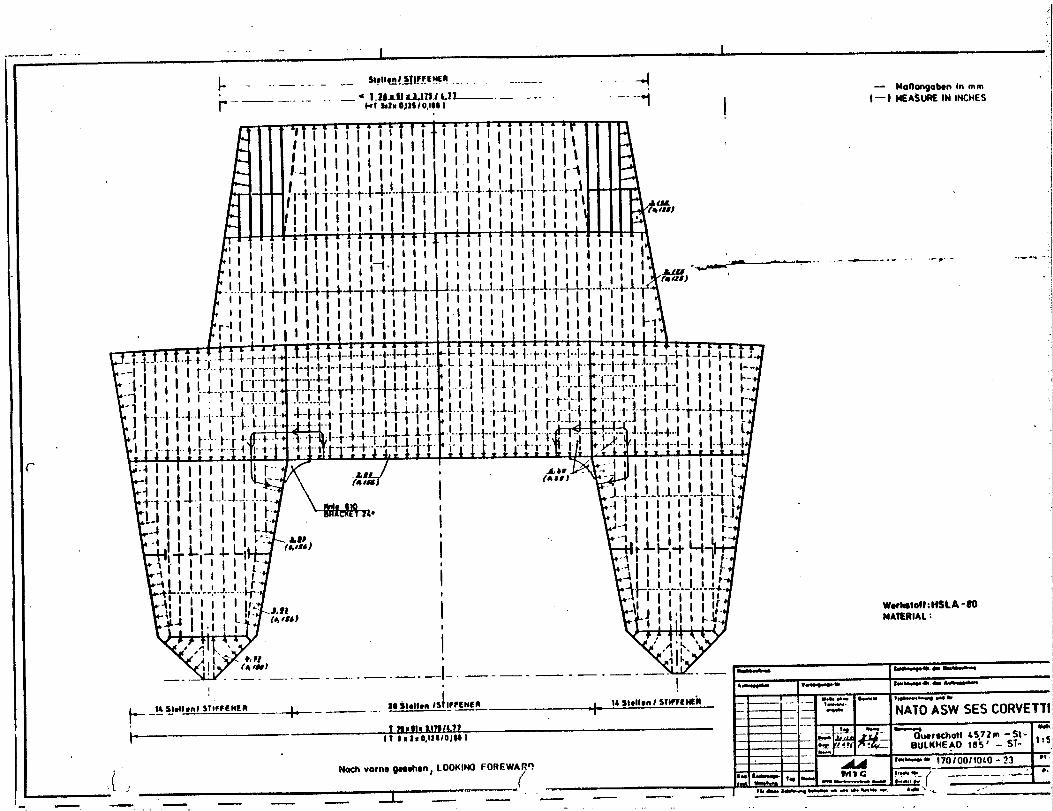
-
—-
IIi1-1.
....
,...”’
;btII,I.
-----—
—.
——
.-
.-—l~
——-$——
-i----
._
—$
_*---
d---,
:---*---+
----~T
+--’--k--*,-—
——
r●
+----*,: LL-;--b
-:-’F*.--
—-
—---
----—
-<+*_—
--—
*--●
t--—
—----
---.-
—-—
---~-—-
“++-”-+-+;-—
--d
++-+-+
-+-U●.
——
—-
+-—-__
+----
.~+-_,--*
-A-*
—-
—4
—--
-_--y-—
---
● .=--+-..
-+
_-—
--:_-
___-+-----
d++-:—
y+~—
--—-
i---”“--
--1:
_-:~“<;
--:--:--~.+__—
4--:
-,-pI
.—-—
-—-—
-—
*----
XL:i
+–~-p
,-—
--,----
*---—
.—-—
—*_—
—----
---—
--.
——
—-
-—----●----
-.--
-—--”
—---
*y~,
__-_!
--—-
●+_._-
+--&
IIIIIiII
,,1I1III>1
IIIII
.-
1 :1
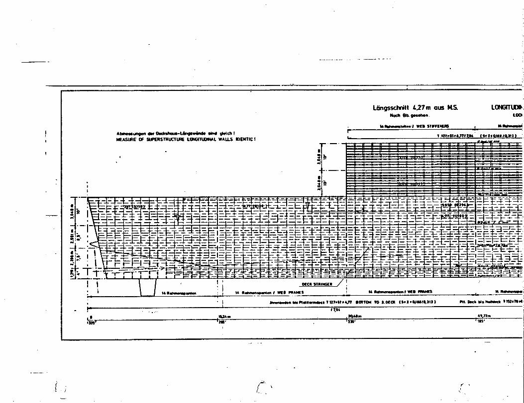
—- -.. .-.-.-— . .------ - - -
.
I
I
I
-—.—
, G &
I a.-I . E
--—’ — — — . —-- - —.—k ---
&
I
0-.%=..
-1 - --l-t : 1 I 1 1 1 1 I 1 . i 1 , , , ,, , , 1 1 1
Q —.&. - 1 u m m I n 1 r r F-1 —
II 11’ II
.1
IOtcnSWINGER ,I
* i 1 I .. m---------- :1 .. .— ---- . -* -.-< um—1-~ u~
—.- .
.
,s; i“\-.

...
..............
...........
.:-.,
,..,..
,....;$.,
..
...
...
--——-.
-...
.
-—-
-.4
.*.U
It-O
mlo
aloLk
~
I
.:4
0
ii
.
-.
[ :.
I1●a
.,.
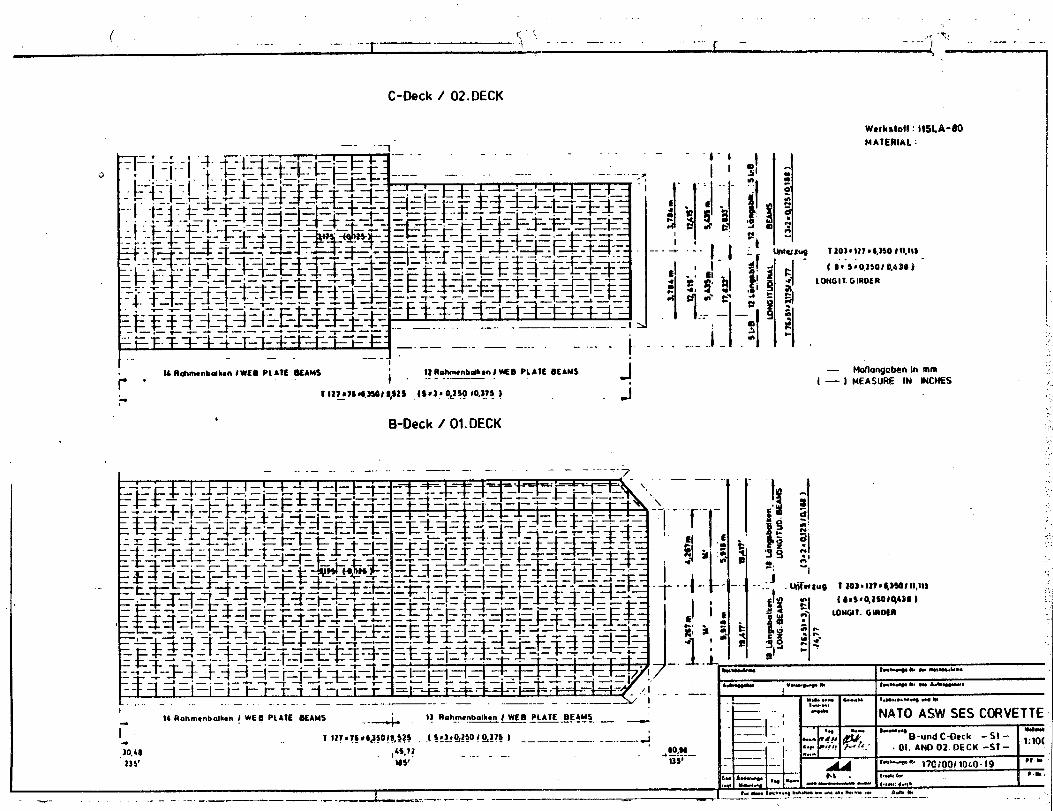
,.
( <: :,. -.+.
*,{..1 --—. —---
. .. . . . ..r —. -.. 1 — .. -—-. —..
Wcrkdot! : IW.A-UOMAIERIAL:
C-Qeck i 02.DECK
0
fLONG I!. G IRoER
—.—— —.- —— ....- ----t-.——-,
. .,,
— Motlangobonin mm:;.,
/ — ) MEASURE IN 6NCMES ‘.13RalWn@nbdkm I ~0 PLAIE BEAMS
i “ “--”””— JIA Itdmwnbdbn lWEO PIA?E OEAMSr“I
‘-111?97C*,JSOI9,$2s (9t3f o<~5010,115)— J
bB-Deck / 01. DECK
,..,:,:..
— .. .— -. -—. . .---- —--— . .—— -. ...= .+/,\\
—— . ,. .,$:..
---1 I
I 111I ,.
.,
ls--B— l-–t- l---i -++-+ -++-+ –+:-+ I I I I -: –1 ...
I-. .,
.’.,.
I*.”,
NATO ASIN SES CORVETTE
. 0!. AND02. DECK-ST-t-b.-w ,y~j~(), ,~~o.lg ●1&
*.W,—- ,,,dle,..,,
#.w 1*....* --- .- . . . .. 9. A- * . .. . .
14 Rahmwbalken ! WE S PLAIE WAU5--4
t] ilohmmbdhcn I WEB PLATE BEAMS-. —— . —— .-. -.— —
r 1 12?.?* ●q3*o!e, $s* .( !:I*%?!O ! Q!?? J -— —— --- —. .—. .— g
,30.48 ,45.71 60 M
1)5’—. 4 —!-.—
185’ 1351
1. ---- —..-. -.— - ——_ .= --— —... —.: -— — — -———--

.
IIII7“‘-,:../
18’
uIIII.11,1 IIi’-.
,,,IIIIII.+II
.L
.—.-d
.-—”*-–”–’–-–-J
i
I
..
.-—

1 [
Ha@d@cbI/ MAIN DECK
#idMutt / 2WXU
- ~--t-l ~ m-s
—— -—
i“.,
l— .—

-,,-
,...
“1-7+%
.
.—
------.
..
..L
——
.--
.—-.
--
..... J,.p
-
A..
-..-—
.-.
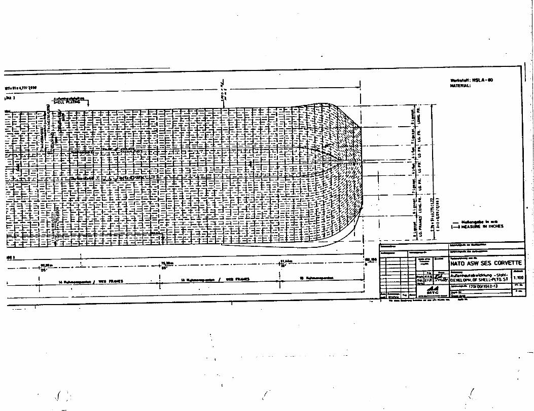
,..
...
..—
...
.-●
~-1-I11+-”-1-’
‘-:
i:0!...! .-.!I,Iis~k+—
.*IiIiiiijatiiIII-.Iii-U:sT
-1I
!
...
.
“\;
...
.

.—
/1. .
.J—. “-L— -=-’ “—- —“-”
I
“— “— —’ -—. .— -
/
‘{‘i., “(
P!aWarmdwk / 3. OECKi
I /,, \
-i —-—”–-—-—-—-—an ,Wa- ------ 4ss q. \—.— .—. — .— .—. — .—. — .—. —/’—-—“
-—.—.— .—. —
I.,
‘,‘\
.—. — .—. —.— -—. —.— .— .— .—
—,. —.— .—. —. —-—.
-M19mn # -s mA!89 4n mu b (,,.,,,
‘\
w --14- -“ Bw_.— .—. — . . . —-— -—-—- —. —- —- —+-—-— —-—-—-— -~- —-—-—-—
.
.—. —
—. _. J!!J+._.—.—
‘\ —-—----—_— .—. —-—
.
I ..—
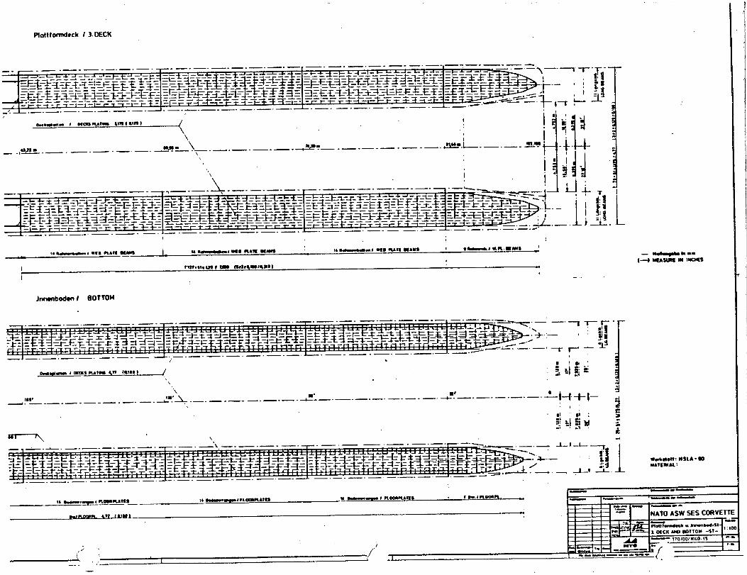
I[ m
lvnm
,1,
cl4
0 ~-----!.+
.-.+a--,
~II
I
Giii’i41
1.1.!+
.,;
-
,.’,I
“r~
i“
\lIii
IIAt\
I‘t
I\.
:\II,
-./.,
Ii,
.,
iIi
‘hill
jql
.III
1- ili
IIi,/
IIi~?
I8
“x
,\..-1
.I